DIXIE-NARCO, INC. Operation and Service Manual First Production 0773-6201CS September 1994 SIID ELECTRONIC VENDERS WITH TWO BUTTON PROGRAMMING Dixie-Narco, Inc. P.O. Box 719 Williston, SC 29853 (800) 688-9090 (803) 266-5000 Revised 7/15/99 803,902,510.31
Transcript
DIX
IE-N
AR
CO
, IN
C.
Operation and Service ManualFirst Production 0773-6201CS
September 1994
SIID ELECTRONIC VENDERSWITH TWO BUTTON PROGRAMMING
ELECTRICAL PARTS AND FUNCTIONS ................................................................................................. .............. 26CORRECT CHANGE LAMP ............................................................................................................ ................................................................ 26SOLD OUT SWITCHES ................................................................................................................................................................................... 26VEND MOTOR ................................................................................................................................................................................................. 28VEND MOTOR SWITCH .................................................................................................................................................................................. 28VEND MOTOR WIDE COLUMN...................................................................................................................................................................... 28VEND MOTOR NARROW COLUMN .............................................................................................................................................................. 29
CAM INSTALLATION AND REMOVAL ................................................................................................... ............... 32TO INSTALL A VENDING CAM: ...................................................................................................... .............................................................. 32TO INSTALL AN ADJUSTABLE CAM: .................................................................................................. ........................................................ 32TO REMOVE AN ADJUSTABLE CAM: ................................................................................................... ....................................................... 32TO REMOVE THE VENDING CAM: ............................................................................................................................................................... 32
TIMING ..................................................................................................................................................................... 32TO SET THE TIMING OF A NARROW COLUMN VEND MOTOR: ............................................................................... ................................ 32TO SET THE TIMING OF A WIDE COLUMN VEND MOTOR: ................................................................................. ..................................... 33REAR SPACER ............................................................................................................................................................................................... 33
CLEANING THE VENDER ....................................................................................................................................... 37WHAT TO CLEAN .................................................................................................................. ......................................................................... 37
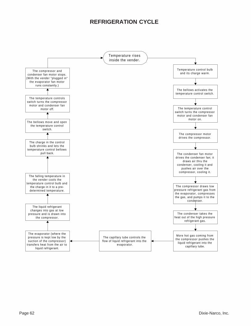
LUBRICATING THE VENDER ......................................................................................................... ........................ 37TEMPERATURE CONTROL ADJUSTMENTS ................................................................................................ ........ 38SIID VENDING .........................................................................................................................................56SIID COIN / CURRENCY .........................................................................................................................57SIID SOLD-OUT MESSAGE ....................................................................................................................59SIID SELECT PANEL / DISPLAY ...........................................................................................................60REFRIGERATION PARTS AND FUNCTIONS .............................................................................................. .......... 62
MECHANICAL PARTS ............................................................................................................... ..................................................................... 62ELECTRICAL PARTS ............................................................................................................... ...................................................................... 62
Page 4 Dixie-Narco, Inc.
GENERAL INFORMATION
INTRODUCTION
Please read this manual in its entirety. This service information is intended to be used by a qualified service technicianwho is familiar with proper and safe procedures to be followed when repairing, replacing or adjusting any Dixie-Narcovender components. All repairs should be done using genuine Dixie-Narco factory parts. Repairs should be performedby a qualified service technician who is equipped with the proper tools and replacement components, using genuineDixie-Narco Factory Parts.
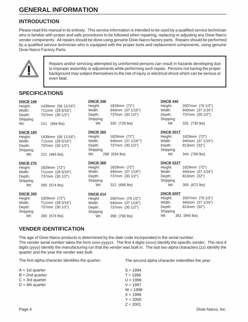
The age of Dixie-Narco products is determined by the date code incorporated in the serial number.The vender serial number takes the form xxxx-yyyyzz. The first 4 digits (xxxx) identify the specific vender. The next 4digits (yyyy) identify the manufacturing run that the vender was built in. The last two alpha characters (zz) identify thequarter and the year the vender was built.
Repairs and/or servicing attempted by uninformed persons can result in hazards developing dueto improper assembly or adjustments while performing such repais. Persons not having the properbackground may subject themselves to the risk of injury or electrical shock which can be serious oreven fatal.
Dixie-Narco, Inc. Page 5
INSTALLATION & SET-UP
The Dixie-Narco SIID can and bottle vender is designedutilizing the latest technology. The SIID Electronic Venderfeatures a highly sophisticated, microcomputer based con-trol system and is designed to meet the growing need foraccountability, multi-pricing, programmability, and systemdiagnostics in can vending equipment. Along with thesefunctions, DEX/UCS-communications to a hand-held com-puter is available to provide the ability to measure eachvending location for product performance, vender perfor-mance, and accessing accounting data. This data can beused to maximize the efficiency of routes for servicing vend-ers. DEX communications also provides the bottler secu-rity for the integrity of the “cash in” versus the “productsold”. The vender design provides the flexibility requiredfor the changing beverage industry as well as dependableperformance for many years.
This manual will assist with proper vender installation andset-up. Please read this manual carefully and becomefamiliar with the SIID Vender before placing the vender onlocation.
RECEIVING INSPECTION
After receiving the vender, inspect it for any shipping dam-age. If there is any damage have the driver note the dam-age on the bill of lading and notify Dixie-Narco. Althoughthe terms of sale are FOB shipping point, which requirethe consignee to originate shipping damage claims, Dixie-Narco will gladly help if you must file a claim.
UNPACKING THE VENDERS
Remove the stretch wrap and top cover from the vender.If flavor labels were shipped with your vender they will beaffixed to the back of a vender in the shipment or in thecash box.
DO NOT STORE THE VENDER OUTSIDEWITH THE STRETCH WRAP ON.THIS COULD CAUSE THE STRETCHWRAP TO BOND TO THE VENDER’SSURFACE, WHICH COULD DAMAGE THEFINISH.
Remove the shipping boards from the bottom of the vender.The shipping boards are attached by the leveling legs.Usea 1-1/2” “socket-type” wrench to unscrew the leveling legsand remove the shipping boards. Be sure to replace thelegs after removing the shipping boards.To open the vender, locate the door lock keys that aresecured inside the coin return cup. After unlocking thedoor, rotate the “T”-handle counter-clockwise until the doorcan be opened. Once inside, check the coin box on thedoor for any additional parts, pricing labels, or informationconcerning factory equipped accessories. Check the “T”-handle for proper alignment and locking functions. Checkthe lamps for proper installation.
ENSURE THAT POWER ISDISCONNECTED FROM THEVENDER OR THAT THE POWERINTERRUPT SWITCH (IF PROVIDED)IS NOT DEFEATED BEFOREINSPECTING OR REPLACING THELAMPS. FAILURE TO COMPLY WITHTHESE INSTRUCTIONS MAYSUBJECT THE USER TO THE RISKOF INJURY OR ELECTRICALSHOCK, WHICH CAN BE SERIOUSOR FATAL.
ELECTRIC POWER NEEDED
Refer to the cabinet serial number plate to determine theproper voltage and frequency the machine requires (do-mestically this requirement is 115 Volts, 60 Hertz). Do-mestic venders will operate properly at +/- 10% of the speci-fied voltage. For domestic models this is between 103volts and 127 volts. The cabinet serial plate also indicatesthe amperage of the vender. Single phase, alternatingcurrent is required. The vender must be plugged in itsown properly rated circuit with its own circuit protection(fuse/circuit breaker).DO NOT USE AN EXTENSION CORD.
GROUND THE VENDER
The vender is equipped with a three wire power supplycord and MUST be plugged in a properly grounded outlet.
DO NOT REMOVE THE GROUND PIN ORIN ANY WAY BYPASS THE GROUNDINGOF THE VENDER.
If the outlet will not accept the power cord plug, contact anelectrician to install a proper AC outlet.
FAILURE TO COMPLY WITH THESEINSTRUCTIONS MAY SUBJECT THEUSER TO THE RISK OF INJURY ORELECTRICAL SHOCK THAT CAN BESERIOUS OR FATAL.
Page 6 Dixie-Narco, Inc.
COIN CHANGERS & OTHERACCESSORIES
COIN CHANGERS
The SIID vender must have a coin changer installed. Ifthe coin changer and other accessories are not factoryinstalled refer to the instructions received from the manu-facturer of the coin changer and other accessories forproper set-up and installation.
The SIID vender will support the following coin changers:
•Micro-Mech/Controller 110 V (12 pin) Changers(Domestic)
Mars TRC 6000Coinco 9300LMaka USPX001
•Micro-Mech Controller 24 V (15 pin) Changers(Domestic)
Mars TRC 6010 XVCoinco 9302LF
DO NOT USE 24 V (12 PIN) CHANGERS.USE OF 24 V (12 PIN) CHANGERS WILLCAUSE DAMAGE TO ELECTRONICSPACKAGE AND CHANGER.
Hang the coin changer on its mounting plate and secure itby tightening the three securing screws. Plug the coinchanger into the 15 pin Jones socket or the 6 pin socketfor MDB changers in the vender. The 15 pin Jones socketis designed to accept the 12 pin plug used on 110 V con-troller style coin changers.
POWER MUST BE REMOVED FROM THEDOOR BEFORE PLUGGING IN THE COINCHANGER OR THE COIN CHANGER MAYNOT POWER ON PROPERLY. IF A BILLACCEPTOR IS BEING USED, THE BILLACCEPTOR MUST BE INTERFACED TOTHE SIID CONTROL BOARD.
After restoring power, manually load the coin changer cointubes with at least 10 coins each. Following the program-ming instructions for the SIID Vender, program each se-lection for its own vend price. A price of $0.00 is free vend.After the pricing is set return the vender to its operate modeeither by closing the door or pulling the door closed switchout. “Prime” the coin changer by making a correct changetransaction.
Note: If using a Mars TRC-6000 coin changer, functionswitch #4 in the coin changer must be set in theoff position (down).
BILL ACCEPTORS
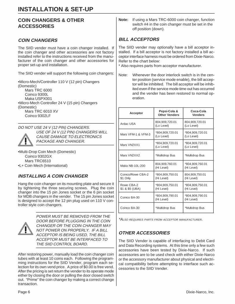
The SIID vender may optionally have a bill acceptor in-stalled. If a bill acceptor is not factory installed a bill ac-ceptor interface harness must be ordered from Dixie-Narco.Refer to the chart below:* Also requires parts from acceptor manufacturer.
Note: Whenever the door interlock switch is in the cen-ter position (service mode enable), the bill accep-tor will be inhibited. The bill acceptor will be inhib-ited even if the service mode time out has occurredand the vender has been restored to normal op-eration.
*ALSO REQUIRES PARTS FROM ACCEPTOR MANUFACTURER.
OTHER ACCESSORIES
The SIID Vender is capable of interfacing to Debit Cardand Data Recording systems. At this time only a few suchaccessories have been tested by Dixie-Narco. If suchaccessories are to be used check with either Dixie-Narcoor the accessory manufacturer about physical and electri-cal compatibility before attempting to interface such ac-cessories to the SIID Vender.
INSTALLATION & SET-UP
rotpeccA&aloC-ispePsredneVrehtO
aloC-acoCsredneV
ASUcadrA10.027,909,408
)leveLoL(10.027,909,408
)leveLoL(
3-MFV&1-MFVsraM10.027,909,408*
)leveLoL(10.027,909,408*
)leveLoL(
1XX2NVsraM10.027,909,408*
)leveLoL(10.027,909,408*
)leveLoL(
2XX2NVsraM suBporditluM* suBporditluM*
002-L01-BNakaM10.067,909,408
)leveLiH(10.067,909,408*
)leveLiH(
2-ABCewoR/ocnioCylnO1$
10.057,909,408*)leveLiH(
10.057,909,408)leveLiH(
2-ABCewoR)ABU(5$&1$
10.057,909,408*)leveLiH(
10.057,909,408*)leveLiH(
03-ABocnioC10.097,909,408*
)leveLiH(10.097,909,408*
)leveLiH(
03-ABocnioC suBporditluM* suBporditluM*
Dixie-Narco, Inc. Page 7
INSTALLATION & SET-UP
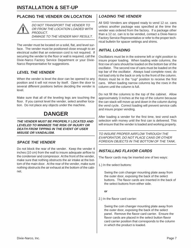
PLACING THE VENDER ON LOCATION
DO NOT TRANSPORT THE VENDER TOOR FROM THE LOCATION LOADED WITHPRODUCT.DAMAGE TO THE VENDER MAY RESULT.
The vender must be located on a solid, flat, and level sur-face. The vender must be positioned close enough to anelectrical outlet that an extension cord is not required. Ifsecuring the vender to the floor or wall is required, call theDixie-Narco Factory Service Department or your Dixie-Narco Representative for suggestions.
LEVEL THE VENDER
When the vender is level the door can be opened to anyposition and it will not move by itself. Open the door toseveral different positions before deciding the vender islevel.
Make sure that all of the leveling legs are touching thefloor. If you cannot level the vender, select another loca-tion. Do not place any objects under the machine.
DANGERTHE VENDER MUST BE PROPERLY LOCATED ANDLEVELED TO MINIMIZE THE RISK OF INJURY ORDEATH FROM TIPPING IN THE EVENT OF USERMISUSE OR VANDALISM.
SPACE THE VENDER
Do not block the rear of the vender. Keep the vender 4inches (10 cm) from the wall to insure adequate airflow tothe condenser and compressor. At the front of the vender,make sure that nothing obstructs the air intake at the bot-tom of the main door. At the rear of the vender, make surenothing obstructs the air exhaust at the bottom of the cabi-net.
LOADING THE VENDER
All SIID Venders are shipped ready to vend 12 oz. cansunless another package was specified at the time thevender was ordered from the factory. If a package otherthan a 12 oz. can is to be vended, contact a Dixie-NarcoFactory Service Representative or refer to the proper tech-nical bulletin for spacer settings and shims.
INITIAL LOADING
Oscillators must be in the extreme left or right position toinsure proper loading. When loading wide columns, thefirst row of cans should be loaded on the bottom bar of theoscillator. The second row of cans must be loaded on thetop bar of the oscillator. Always load complete rows; donot load only to the back or only to the front of the column.Rotors must be in the “cup” position to receive the firstcans. When loading narrow columns lay the rows in thecolumn until the column is full.
Do not fill the columns to the top of the cabinet. Allowapproximately 3 inches at the top of the column becausethe can stack will move up and down in the column duringthe vend cycle. Correct loading will prevent service callsand insure proper vending.
After loading a vender for the first time, test vend eachselection with money until the first can is delivered. Thiswill ensure that the vender is loaded and working properly.
TO INSURE PROPER AIRFLOW THROUGH THEEVAPORATOR, DO NOT PLACE CANS OR OTHERFOREIGN OBJECTS IN THE BOTTOM OF THE TANK.
INSTALLING FLAVOR CARDS
The flavor cards may be inserted one of two ways:
1.) In the select buttons:
Swing the coin changer mounting plate away fromthe outer door, exposing the back of the selectbuttons. The flavor cards are inserted in the back ofthe select buttons from either side.
or
2.) In the flavor card carrier:
Swing the coin changer mounting plate away fromthe outer door, exposing the back of the selectpanel. Remove the flavor card carrier. Ensure theflavor cards are placed in the select button flavorcard carrier position that corresponds to the columnin which the product is loaded.
Page 8 Dixie-Narco, Inc.
FEATURES
The following is a description of all the features of the SIID.
DEX Compatible Hand-held InterfaceThe vending industry (NAMA) has established an auditdata protocol which is defined by DEX (Direct ExchangeOf Data) and UCS (Uniform Communications Standards).This interface is a direct connect as defined by the speci-fication. The SIID has provisions for an internal and exter-nal connection. The external connection provides a lim-ited amount of information.
The internal connection provides the full capability of DEX/UCS. These capabilities include full audit of interval andhistorical data, system programming, diagnostics, and lim-ited access.
10 Column Stack CompatibleThe SIID Controller is capable of driving up to 10 stackmotors independently. The motors are 110 VAC. Thevend switches and sold-out switches are low voltage, goldcross-point switches. The interface for the cam positionand empty detection is located on the controller board.
Low Voltage Select PanelThe select panel consists of gold cross-point switches. Theinterface circuitry is located on the controller board. Thecontroller board supports up to 10 selections.
Programmable Space-To-SalesProgrammable space-to-sales allows columns to be as-signed to select buttons. Columns are dispensed evenlywhen more than one column is assigned to a select buttonor group of select buttons.
Select Panel Controller Programming orHand-held Controller ProgrammingThe SIID vender has the capability to be programmedthrough the select panel. The SIID vender can also beprogrammed through the DEX port with the same hand-held device used to access the accounting data.
LED Display (Light Emitting Diodes)Optional LCD Display (Liquid Crystal Diodes)Early displays consist of 4 characters utilizing 7 segmentLEDs for each character to provide a true alpha-numericdisplay. Current display boards consist of four, fourteensegment LEDs to provide clearer alpha-numeric charac-ters. The display is implemented on its own printed circuitboard.
Sold Out Message/SelectionEach selection is supported by a sold-out message. Whena given selection is sold-out and that selection is pressed,“SOLD Out” will scroll across the display.
SIID HARDWARE CONFIGURATION
The hardware configuration for the SIID Controller con-sists of a main control board and a display board. Theselect panel consists of low voltage switches. Sold-outindicators have been eliminated in the SIID. The selectswitches interface directly to the main controller.
The motors used on the stack continue to be 115 VAC.The vend switches and sold-out switches are low voltage.There is only one vend switch per motor and one sold-outswitch per column. The motors, vend switches, and sold-out switches directly interface to the main controller board.Each motor is independently controlled to provide themaximum flexibility for space to sales. The Main Control-ler supports up to 10 motors and 10 selections.
The Main Controller consists of one board. It consists ofall the intelligence, memory, switch interfaces, stack inter-face (motors, vend switches, and sold-out switches), andperipheral interfaces which include coin changers, dollarbill validators, DEX interface and debit systems.
The DEX interface supports both an internal connectionas well as an external connection. The interconnect is a1/4" phono jack as specified and approved by NAMA. Allelectrical specifications, protocols, and baud rates are iden-tified in the specification.
The door switch is included to determine door accesses.A service switch is located on the main controller board toaccess accounting data, programming features, and ac-cess diagnostic features through the front select panel.
A real time clock (RTC) with battery backed memory isprovided so memory can be maintained during power fail-ures. The life expectancy is 5 years shelf life and 10 yearsoperational. The real time clock is displayed in militarytime (24-hour clock). The RTC is used for time stampingdoor closures, power outages, limited access, and selec-tive discount pricing.
The intelligence of the Main Controller is an Intel 80C32microprocessor. A minimum of 128k of EPROM and 8k ofRAM (battery backed) is provided.
Early Display Boards consisted of four, seven segmentLEDs to provide alpha-numeric characters. Current Dis-play Boards consist of four, fourteen segment LEDs to pro-vide clearer alpha-numeric characters. Also, the exactchange indicator consists of an LED.
INSTALLATION & SET-UP
Dixie-Narco, Inc. Page 9
INSTALLATION & SET-UP
Price Displayed when Selection is pressedThe operation of the vender in the ready mode providesthe customer the price of any selection when that particu-lar select button is pressed. If all selections are set at thesame price in primary set price and the same price in sec-ondary set price, the vend price is displayed at all times onthe display.
Single Price/Multi-Price via Select Panel or Hand-heldPrices for each selection are programmed eitherthrough the front select panel or through the DEX hand-held device. For single price configuration, each selectionmust be programmed for the same price.
Accounting Data ProvidedThe accounting features are accessed through the frontselect panel. These include (HD) historical data, which isnot resettable, and (RD) resettable data, which isresettable.
(HD) Historical Data Includes - the total cash collectedby the vender, the total number of vends by thevender and the number of vends by each selec-tion.
(RD) Resettable Data Includes - the total cash collectedsince the last counter reset, the total number ofvends since the last counter reset, the number ofvends by each selection since the last counter re-set and allows the resettable data to be zeroed.
The types of data that can be retrieved via the DEX inter-face to a hand-held device is addressed in the SIID AuditFeatures section.
Limited Access on Selection (Time, Days, Price)The limited access feature allows each selection to be in-hibited with respect to time and selected days of the week.Also, prices of selections can be altered (Happy Hour) withrespect to time and selected days of the week.
Multiple Coin Changer InterfacesThe SIID Controller supports the following coin changerinterfaces.
Low-Level/Hi-Level/MDB Bill ValidatorsArdac USA, Mars VFM-1, VFM-3 and Mars VN2000Series, Maka, Coinco/Rowe CBA-2 ($1 only), Rowe CBA-2 $1 and $5 (UBA), and Coinco BA-30 Bill Validators inter-face to the SIID Controller. Also, validators which inter-face to the new MDB (Multi Drop Bus) specification shouldalso be compatible, but have not been tested and approvedas of this publication. If a bill acceptor is not factory in-stalled, an interface harness will need to be ordered fromDixie-Narco, and/or the bill acceptor manufacturer.
Verifone/Debitek Card CompatibleThe SIID is capable of interfacing to Debit Card and Datarecording systems. At this time only a few such accesso-ries have been tested by Dixie-Narco. If such accesso-ries are to be used check with either Dixie-Narco or theaccessory manufacturer about physical and electrical com-patibility before attempting to interface such accessoriesto the SIID vender. The SIID supports any Debit Card/Data Recording manufacturer’s systems that meet NAMAII protocol.
Page 10 Dixie-Narco, Inc.
DEX stands for Direct Exchange of data, which meansthere is a hard-wired connection between the two systemsexchanging data. This is done by inserting a ¼ inch phoneplug on the portable data collection device in a jackmounted on the SIID. Inserting the plug automatically ini-tiates the exchange of data, which takes several seconds.No other machine functions are available while the ex-change is taking place. The operator is told that the ex-change is taking place by the display of the message “DEXIN PROGRESS”. Most of the data records are reported inboth an interval and historical format. The historical val-ues represent a total of the values since the machineshipped from the factory. The interval values are the datacollected since the last time it was collected electronically.
The following types of audit data are accessible electroni-cally:
Machine Identity InformationDate and Time of InterrogationCash Sales SummaryCash Input and Output SummaryProduct Sales InformationMachine ConfigurationEvents: Door Openings
InterrogationsProgrammable Access LimitsTime of Day Discounts
In addition to retrieving audit data, every machine configu-ration parameter that can be programmed in the servicemenu can be programmed electronically via the DEX port.
The following types of data can be configured electroni-cally:
Machine IdentityDate and TimePrice and Product InformationSpace to SalesLimited Access Control ParametersTime of Day Discounts Control ParametersEscrow Mode *
* Escrow mode cannot be transferred with the NorandDevice.
INSTALLATION & SET-UP
SIID AUDIT FEATURES
The SIID provides two methods of accessing audit data.A limited amount of audit information is available in thesystem set-up/audit menu. More extensive audit informa-tion is accessible electronically.
SYSTEM SET-UP/AUDIT MENU
Six types of audit data are available in the system set-up/audit menu: Historical Data (HD) which includes total cashcollected, total vends and the total number of vends byeach selection; Resettable Data (RD) which includes totalcash collected since last counter reset, total vends sincelast counter reset and total number of vends by each se-lection since last counter reset.
The audit data is accessed by pressing the system set-up/audit switch. The display shows “HD” . Pressing selectbutton “1” displays the total cash collected by the vender.Pressing select button “2” displays the total vends by thevender. Pressing select button “3” displays the total num-ber of vends by each selection. Each selection is auto-matically scrolled across the display. Pressing select but-tons “1” and “2” simultaneously will move to the next func-tion. The display will show “RD”. Pressing select button“1” displays the total cash collected since the last counterreset. Pressing select button “2” displays the total vendssince the last counter reset. Pressing select button “3”displays the total number of vends by each selection sincethe last counter reset.
ELECTRONIC ACCESS
A much more extensive amount of audit information is ac-cessible electronically. It is retrieved with a portable datacollection device and typically loaded in a computer at acentral location. The data can then be tracked with a database, for preparing route stocking lists, tracking cash flow,doing inventory control and other tasks. Data collectiondevices are available from several sources including:Norand, Fujitsu, Panasonic, Telxon, Verifone and Mars.Dixie-Narco currently collects data with a PC program run-ning on a portable notebook computer.
The SIID uses the DEX/UCS protocol as the method ofexchanging data with the portable data collection device.DEX/UCS was formally adopted as the standard methodof collecting audit data for the vending industry by the Na-tional Automatic Merchandising Association (NAMA) inApril of 1991. DEX/UCS has been used in related indus-tries since 1989. It was developed by the Arthur D. LittleCompany and is administered and maintained by the Uni-form Code Council (UCC). The NAMA Vending Electron-ics Standardization Committee developed and publisheda comprehensive set of data records relevant to the vend-ing industry. The SIID reports the portion of these relatedto this specific machine design. The current list of recordsand their usage by the SIID follows.
Dixie-Narco, Inc. Page 11
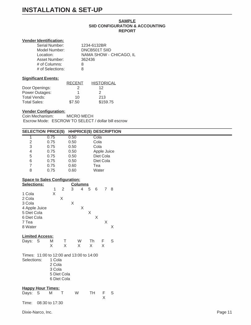
SAMPLESIID CONFIGURATION & ACCOUNTING
REPORT
Vender Identification:Serial Number: 1234-6132BRModel Number: DNCB501T SIIDLocation: NAMA SHOW - CHICAGO, ILAsset Number: 362436# of Columns: 8# of Selections: 8
1 2 3 4 5 6 7 81 Cola X2 Cola X3 Cola X4 Apple Juice X5 Diet Cola X6 Diet Cola X7 Tea X8 Water X
Limited Access:Days: S M T W Th F S
X X X X X
Times: 11:00 to 12:00 and 13:00 to 14:00Selections: 1 Cola
2 Cola3 Cola5 Diet Cola6 Diet Cola
Happy Hour Times:Days: S M T W TH F S
XTime: 08:30 to 17:30
INSTALLATION & SET-UP
Page 12 Dixie-Narco, Inc.
INSTALLATION & SET-UP
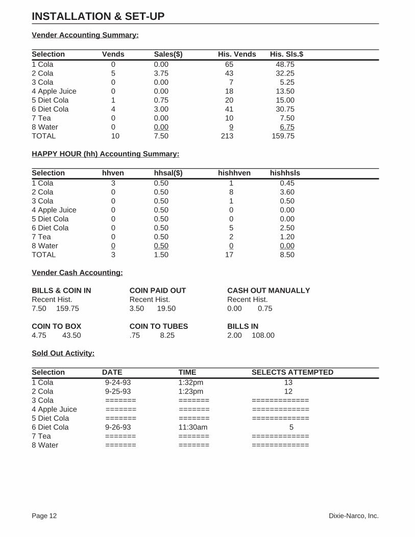
Vender Accounting Summary:
Selection Vends Sales($) His. Vends His. Sls.$1 Cola 0 0.00 65 48.752 Cola 5 3.75 43 32.253 Cola 0 0.00 7 5.254 Apple Juice 0 0.00 18 13.505 Diet Cola 1 0.75 20 15.006 Diet Cola 4 3.00 41 30.757 Tea 0 0.00 10 7.508 Water 0 0.00 9 6.75TOTAL 10 7.50 213 159.75
HAPPY HOUR (hh) Accounting Summary:
Selection hhven hhsal($) hishhven hishhsls1 Cola 3 0.50 1 0.452 Cola 0 0.50 8 3.603 Cola 0 0.50 1 0.504 Apple Juice 0 0.50 0 0.005 Diet Cola 0 0.50 0 0.006 Diet Cola 0 0.50 5 2.507 Tea 0 0.50 2 1.208 Water 0 0.50 0 0.00TOTAL 3 1.50 17 8.50
Vender Cash Accounting:
BILLS & COIN IN COIN PAID OUT CASH OUT MANUALLYRecent Hist. Recent Hist. Recent Hist.7.50 159.75 3.50 19.50 0.00 0.75
COIN TO BOX COIN TO TUBES BILLS IN4.75 43.50 .75 8.25 2.00 108.00
Sold Out Activity:
Selection DATE TIME SELECTS ATTEMPTED1 Cola 9-24-93 1:32pm 132 Cola 9-25-93 1:23pm 123 Cola ======= ======= =============4 Apple Juice ======= ======= =============5 Diet Cola ======= ======= =============6 Diet Cola 9-26-93 11:30am 57 Tea ======= ======= =============8 Water ======= ======= =============
Dixie-Narco, Inc. Page 13
INSTALLATION & SET-UP
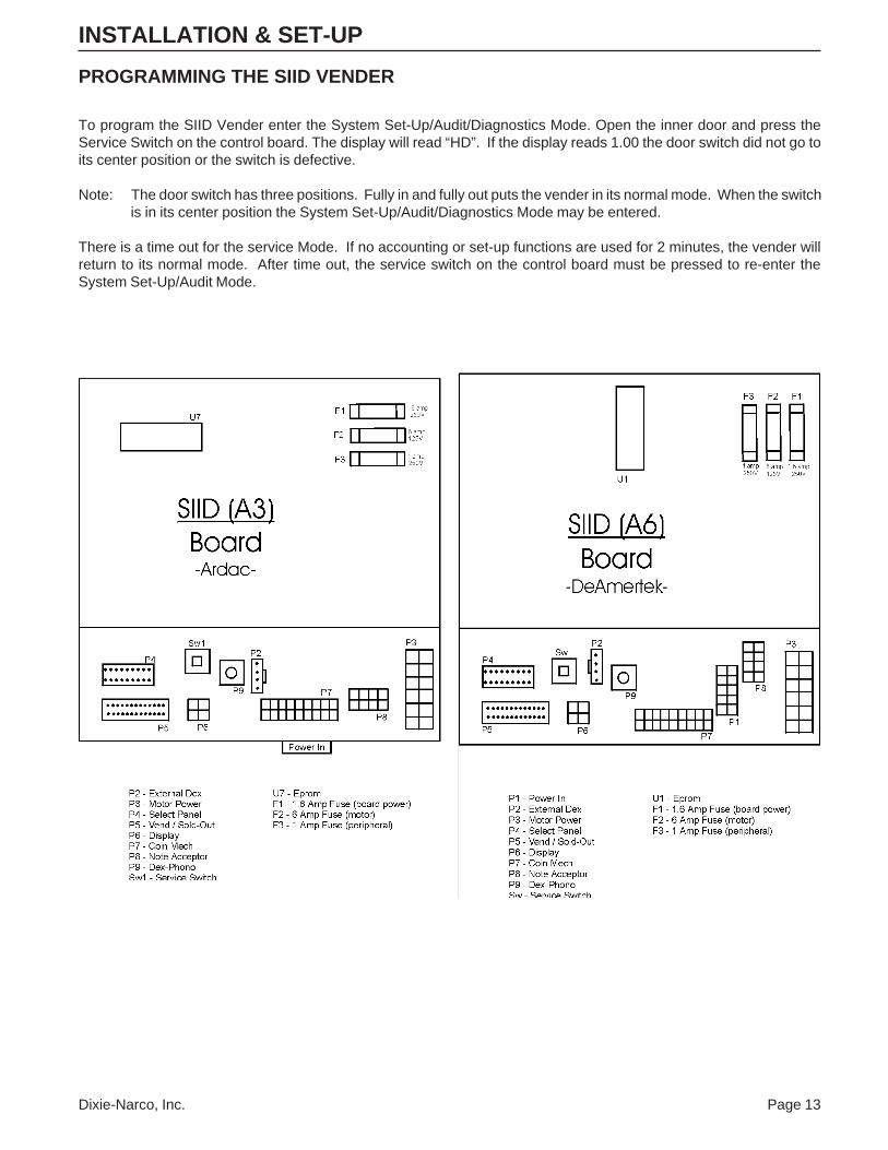
PROGRAMMING THE SIID VENDER
To program the SIID Vender enter the System Set-Up/Audit/Diagnostics Mode. Open the inner door and press theService Switch on the control board. The display will read “HD”. If the display reads 1.00 the door switch did not go toits center position or the switch is defective.
Note: The door switch has three positions. Fully in and fully out puts the vender in its normal mode. When the switchis in its center position the System Set-Up/Audit/Diagnostics Mode may be entered.
There is a time out for the service Mode. If no accounting or set-up functions are used for 2 minutes, the vender willreturn to its normal mode. After time out, the service switch on the control board must be pressed to re-enter theSystem Set-Up/Audit Mode.
Page 14 Dixie-Narco, Inc.
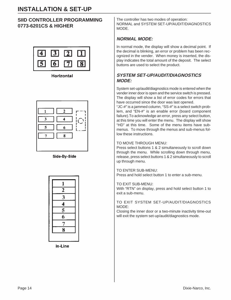
The controller has two modes of operation:NORMAL and SYSTEM SET-UP/AUDIT/DIAGNOSTICSMODE.
NORMAL MODE:
In normal mode, the display will show a decimal point. Ifthe decimal is blinking, an error or problem has been rec-ognized in the vender. When money is inserted, the dis-play indicates the total amount of the deposit. The selectbuttons are used to select the product.
SYSTEM SET-UP/AUDIT/DIAGNOSTICSMODE:
System set-up/audit/diagnostics mode is entered when thevender inner door is open and the service switch is pressed.The display will show a list of error codes for errors thathave occurred since the door was last opened.“JC-#” is a jammed column, “SS-#” is a select switch prob-lem, and “EN-#” is an enable error (board componentfailure).To acknowledge an error, press any select button,at this time you will enter the menu. The display will show“HD” at this time. Some of the menu items have sub-menus. To move through the menus and sub-menus fol-low these instructions.
TO MOVE THROUGH MENU:Press select buttons 1 & 2 simultaneously to scroll downthrough the menu. While scrolling down through menu,release, press select buttons 1 & 2 simultaneously to scrollup through menu.
TO ENTER SUB-MENU:Press and hold select button 1 to enter a sub-menu.
TO EXIT SUB-MENU:With “RTN” on display, press and hold select button 1 toexit a sub-menu.
TO EXIT SYSTEM SET-UP/AUDIT/DIAGNOSTICSMODE:Closing the inner door or a two-minute inactivity time-outwill exit the system set-up/audit/diagnostics mode.
INSTALLATION & SET-UP
SIID CONTROLLER PROGRAMMING0773-6201CS & HIGHER
Dixie-Narco, Inc. Page 15
FRONT PANEL PROGRAMMINGSYSTEM SET-UP/AUDIT/DIAGNOSTICSMENU
HD – HISTORICAL DATAThis section shows the user the vender accounting overthe life of the vender. Use the following select buttons toview the total sales in dollars, total number of vends andthe total number of vends for each selection.
• Press Select Button 1:Shows the historical total cash sales for the life of thevender.
• Press Select Button 2:Shows the historical total number of vends.
• Press Select Button 3:Shows the historical number of vends by selection.Each selection automatically scrolls across thedisplay.
• Press & hold select buttons 1 & 2 simultaneously tomove to the next item on the menu.
RD – RESETTABLE DATAThis section shows the user the vender accounting datasince the time of the last counter reset. This data can bereset either from this menu or by a DEX interrogation.
• Press Select Button 1:Shows the total cash collected since the last counterreset.
• Press Select Button 2:Shows the total number of vends since the lastcounter reset.
• Press Select Button 3:Shows the total number of vends by selection sincethe last counter reset. Each selection automaticallyscrolls across the display.
• Press Select Button 4:This button zeros the resettable data described above.Hold button “4” for 5 seconds and “COUNTERSRESET” will be displayed. At this time all resettabledata will return to “0”.
• Press & hold select buttons 1 & 2 simultaneously tomove to the next item on the menu.
S-P - SET PRICEThis function is used to set the price of each selection.When a select button is pressed, the price for that selec-tion will be displayed. If the button is held in the price willincrement or decrement. To change from increment todecrement, release the select button and press it again.To set all selections for the same price: set desired vendprice on select button #1, then simultaneously press andhold select buttons 3 & 4 for five seconds. This will changethe vend price of all selections, both primary and second-ary, to the price programmed to select button #1.
Note: The SIID’s multi-pricing capability allows you to setall selections to any price in the range of $0.00 to$99.95.
• Press & hold select buttons 1 & 2 simultaneously tomove to the next item on the menu.
C-D - COIN DUMP/COIN FILL MODECOIN DUMP:This section is used to dump coins from the coin mecha-nism while in “C-D” mode.
• Press & hold Select Button 1:Dump Nickels.
• Press & hold Select Button 2:Dump Dimes.
• Press & hold Select Button 3:Dump Quarters.
• Press & hold Select Button 4:Dump 4th tube in 4 tube changers.
COIN FILL MODEThis section is used to count coins loaded in the top (sepa-rator) of the coin mech. Insert coins in the top (separator)of the coin mech. The total value of the coins will be dis-played. The coins will be counted in the DEX audit dataand the SIID controller will know exactly how much changeis in the coin mech.
• Press & hold select buttons 1 & 2 simultaneously tomove to the next item on the menu.
INSTALLATION & SET-UP
Page 16 Dixie-Narco, Inc.
USER - USER OPTIONS MENUThis function is used to configure the vender to operate inthe fashion best suited for the vender location. To moveto diagnostics (DIAG), press & hold select buttons 1 & 2simultaneously; to enter the USER sub-menus press se-lect button 1.
The following are sub-menus of the User Option Menu:“STS”, “TIME”, “DATE”, “ESC”, “LANG”, “PROM”, “ECNT”,“NF”, “CR”, “BILL”, “LIM”, “SEC”, “ACD”, “ “FREE”, “DST”,“DSTR”, “SCE”, “COIN”, “SSM”, “MV”, and “RTN”.
STS - SPACE-TO-SALESTo view the space-to-sales condition, press any select but-ton and the current columns assigned to that select buttonwill display.
To change space-to-sales condition:To Add Selection:Press Service Switch and “ADD” will be displayed.Note: Pressing the service switch will toggle betweenadd and delete. A 10 second inactivity time-out will re-turn to “STS”. Press and hold any select button; which-ever select button you are holding is the select button towhich the additional column will be assigned. While hold-ing the select button, the display will read “ADD #” andthe selection will increment from 1 to 10. Release theselect button when the desired column # to be added isdisplayed. A message will scroll across the display tell-ing you what column will be assigned to the button youwere holding. Press service switch to complete space-to-sales decision and re-enter service mode.
To Remove Selection:Press Service Switch and “ADD” will be displayed. Pressservice switch again and “DEL” will be displayed.Note: Pressing the service switch will toggle betweenadd and delete. A 10 second inactivity time-out will re-turn to “STS”. Press and hold any select button. Theselect button you are holding is the select button fromwhich the additional column will be removed. While hold-ing select button, the display will read “DEL #” and theselections will increment from 1 to 10. Release the se-lect button when the desired column # to be removed isdisplayed. A message will scroll across the display tell-ing you what column will be deleted from the button youwere holding. Press service switch to complete spaceto sales decision and re-enter service mode.
• Press & hold select buttons 1 & 2 simultaneously tomove to the next item on the menu.
TIME - TIMETo display time, press and let go of any select button. Thetime will be displayed in military time (24 hour clock). Tochange the time, press and hold select button 1 or 2 . Thetime will increment or decrement. To change from incre-ment to decrement, release the select button and press itagain.
To change time:• Press & hold Select button 1:
set Hours
• Press & hold Select button 2:set Minutes
• Press & hold select buttons 1 & 2 simultaneously tomove to the next item on the menu.
DATE - DATETo view the date, press and let go of select button 1 or 2.Month and day will be displayed as “X.YY” where “X” rep-resents the month and “YY” represents the day. Pressand let go of button “3” to display day of week. Press andlet go of button “4” to display year.
• Press & hold select buttons 1 & 2 simultaneously tomove to the next item on the menu.
INSTALLATION & SET-UP
Dixie-Narco, Inc. Page 17
ESC - ESCROWThis section supports 4 (four) escrow options. Press anyselect button to show the current escrow condition.
To change the escrow condition:• Press & hold Select Button 1:
“Pr” - Escrow to PriceThe escrow condition is “escrow to price”. All dollarbills will be stacked. No cancel sale is allowed onceminimum vend price is met or exceeded.
• Press & hold Select Button 2:“E-S4” - Escrow to Select 4The escrow condition is “escrow to select” with alldollar bills being stacked. Cancel sale will return thedeposit from the coin changer (i.e. 4 quarters).
• Press & hold Select Button 3:“E-S1” - Escrow to Select 1The escrow condition is “escrow to select”, with thelast dollar bill that meets or exceeds maximum vendprice being escrowed in the validator. Cancel sale willreturn the held dollar bill. Any amount over $1 will bereturned from the coin changer.
• Press & hold Select Button 4:“E-P2” - Escrow No CancelThe escrow condition is “escrow no cancel” with allbills stacked. Cancel sale is not allowed unless thevender is in exact change and the maximum vendprice is exceeded. Note: Any money entered belowthe vend price cannot be returned.
• Press & hold select buttons 1 & 2 simultaneously tomove to the next item on the menu.
LANG - LANGUAGEThis function is used to set the language that will be usedfor display messages. Press select button 1 to display thecurrent language selected. To change the language se-lected, press & hold select buttons 1 and 2 simultaneouslyto scroll through the language menu. Once the desiredlanguage is shown on the display, let go of the buttons.The display will then return to “LANG”.
English ENGL French FRN Dutch DUTGerman GER Italian ITA Slovenia SLOVSpanish SPN Portuguese PORT
• Press and hold select buttons 1 & 2 simultaneously tomove to the next item on the menu.
PROM - PROMOTIONAL SALESThis function is used to initiate a promotional sale.
To show the current promotional condition:• Press Select Button 1:
To show “UN-#”, where # equals the number of vendsrequired to initiate promotion.
• Press Select Button 2:To show “FR-#”, where # equals the number of freebeverages to be delivered after the number of requiredvends have occurred, as programmed, to initiatepromotion.
• Press Select Button 3:To show enabled #’s of the selections that are enabledfor the promotion.
To change the promotional sales conditions:• Press & hold Select Button 1:
The number of vends required to initiate the promo-tional sale will increment from zero to 25 and thenreturn to zero. Release the select button when thedesired number of vends to initiate the promotionalsale is displayed.
Note: If “UN-0”, the promotion is disabled.
• Press & hold Select Button 2:The number of free beverages to be delivered after thenumber of vends have occurred will increment fromzero to 25 and then return to zero. Release the selectbutton when the desired number of free beverages tobe delivered is displayed.
Note: If “FR-O”, the promotion is disabled.
• Press & hold Select Button 3:Display will show “ENABLED SEL # (s) where #shows the selections that are enabled for the promo-tion to occur.
To add or delete selections:• A) Press the service switch. The display will show
“ADD”, indicating selections will be added. Press theservice switch again and the display will show “DEL”,indicating selections will be deleted.
• B) Press and hold any select button. The display willshow “ADD #” or “DEL #”, where # is a select buttonnumber. While holding a select button, the # willincrement from 1 to the maximum select buttonnumber and return to 1.
INSTALLATION & SET-UP
Page 18 Dixie-Narco, Inc.
• C) Release the select button when the desired selec-tion # to be added or deleted is displayed. A messagewill scroll across the display, telling you what selectionwill be added or deleted.
• D) Press the service switch to complete the decision.
NOTE: Only one selection may be added or deleted at atime. The service switch must be pressed beforeand after each change.
Important: Promotional sales, when enabled, will be onat all times of the day.
• Press & hold select buttons 1 & 2 simultaneously tomove to the next item on the menu.
ECNT - ELECTRONIC COUNTERThis function is used to show historical total vends, histori-cal product counts that have occurred for prices being used,and interval product counts for each selection from out-side the vender. To program the SIID to use this function,press any select button. The current setting or four (4)key programming will be displayed. If “——” is displayed,no code is programmed.
To program or to change four (4) key program:• A) Press service switch. Display will show “----”,
indicating the new code is ready to be entered.
• B) Press the four (4) select buttons that are desired tobe in the code. As they are pressed the display willchange to show the four (4) select buttons chosen.Note: Four (4) separate buttons must be used or thepattern will not be saved. Note: Only select buttons 1through 9 may be used.
• C) Press the service switch. The display will changeback to “ECNT”.
To show the current count• hold the four keys programmed for five (5) seconds.
The display will show historical total vends.
To view other data:• Press & hold Select Button 1:
Show historical total vends.
• Press & hold Select Button 2:Show list of prices and historical product counts thathave occurred for those prices.
• Press & hold Select Button 3:Show interval product count for each selection.
• Press & hold Select Button 4 for five seconds:Resets interval data. “COUNTERS RESET” will scrollacross display.
• Press any select button greater than 4 to return thevender to normal operation.
Note: There is a two (2) minute time-out that will returnthe vender to normal vending mode.
• Press & hold select buttons 1 & 2 simultaneously tomove to the next item on the menu.
NF - NOTE FACTOR(for use with foreign note acceptors only)This will only be present in the menu if SET BILLS ONLYis programmed to “BILLS YES”.Some foreign note acceptors that use a pulsed signal toindicate the value of the note being accepted must havethe value of that pulse (the note factor) programmed in thevender. The SIID determines the value of the note in-serted by multiplying the number of pulses counted by theNote Factor programmed.
To show the current Note Factor “NF” condition:• Press any select button and the current value will be
displayed.
To change the Note Factor “NF” condition:• Press and hold any select button. The Note Factor will
increment or decrement from 100 to 10,000. Tochange from increment to decrement, release theselect button and press it again. Note: 100 is $1.00 indomestic use.
NOTE: The coin mech will communicate the decimal pointposition to the SIID control board.
• Press & hold select buttons 1 & 2 simultaneously tomove to the next item on the menu.
CR - CHANGE RULES(for use with foreign L-Plus coin mechs only)Some countries have coin mechs that do not use all threecoin tubes. This would not allow the SIID to come out ofexact change mode. To accommodate this the ChangeRules section allows the SIID to be programmed to usethe tubes necessary for the SIID to not be in an exactchange mode.
To show the current Change Rules condition, press anyselect button. The display will show “ABC”, indicating tubesA, B, and C must have change. “A” refers to the tube onthe left, “C” refers to the tube on the right, and “B” refers tothe tube in the middle.To change the Change Rule Condition:• Select Button 1:
When pressed, enables and disables Tube A.
• Select Button 2:When pressed, enables and disables Tube B.
• Select Button 3:When pressed, enables and disables Tube C.
• Press and hold select buttons 1 & 2 simultaneously tomove to the next item on the menu.
INSTALLATION & SET-UP
Dixie-Narco, Inc. Page 19
BILL - SET BILLS ONLY (SIID Only)This function is used to program the vender to take billsonly.
To show the current “BILL” condition:• Press select button 1 and the current condition will be
displayed.
To change the “BILL” condition:• Press Select Button 1:
When pressed, enables “BILLS YES” mode. You nolonger need to use a changer; the controller willoperate with bills only.
• Press Select Button 2:When pressed, enables “BILLS NO” mode. A changeris needed. The controller will not operate the noteacceptor without a changer.
• Press and hold select buttons 1 & 2 simultaneously tomove to the next item on the menu.
LIM - LIMITED ACCESS MENUThis function is used to program the vender to use theLimited Access Features. To move to Secondary PriceMenu “SEC”, press & hold select buttons 1 & 2 simulta-neously. To enter the sub-menu press select button 1.The following are sub-menus of Limited Access Menu:“LAOS” ,”LAOD” ,”PER1" ,”PER2", and “RTN”.
LAOS - LIMITED ACCESS ON SELECTIONThis function is used to set selection(s) which will be lim-ited during certain periods of the day. Press any selectbutton to view the limited access on selection condition.The display will show “DISABLED” or “ENABLED SEL -#(s), where # shows the selections that are set for limitedaccess. To change limited access on any selection, pressand hold the desired select button until the message dis-played is the desired limited access condition for that se-lection.
ENABLED SEL - #(s) - Selection(s) displayed are on lim-ited access.DISABLED - All selections are not on limited access.
• Press & hold select buttons 1 & 2 simultaneously tomove to the next item on the menu.
LAOD - LIMITED ACCESS ON DAYS:This function is used to set the days of the week for limitedaccess. To view the limited access on days condition,press and let go of any select button. The display willshow “ENABLED ON DAYS - #(s)”
Day of Week:Sunday 1 Wednesday 4 Saturday 7Monday 2 Thursday 5Tuesday 3 Friday 6
To change limited access on days:To Add Days:Press service switch. “ADD” will appear on display.Press and hold any select button to scroll throughdays. Release select button at desired day to turn onlimited access. Press service switch to completelimited access on days decision. This must be donefor each day to be added.
To Remove Days:Press service switch. “ADD” will appear on display.Press service switch again. “DEL” will appear ondisplay. Press and hold any select button to scrollthrough days. Release select button at desired day toturn off limited access on that day. Press serviceswitch to complete limited access on days decision.This must be done for each day to be removed.
NOTE: Only one limited access on days change may bemade at a time. The service switch must bepressed before and after each change.
• Press & hold select buttons 1 & 2 simultaneously tomove to the next item on the menu.
PER1 - PERIOD 1This function is used to set time to start and end limitedaccess. To display PER1 start time, press and let go ofselect button 1 or 2 . To display PER1 end time, press andlet go of select button 3 or 4 .
To Change:• PER1 Start Time:
To change start time, press and hold select button 1 tochange hours, and select button 2 to change minutes.The time will increment or decrement. To change fromincrement to decrement, release the select button andpress again.
• PER1 End Time:To change end time, press and hold select button 3 tochange hours, and select button 4 to change minutes.The time will increment or decrement. To change fromincrement to decrement, release the select button andpress again.
NOTE: Start time has to be less than end time. You mustset an on and off time when using PER1.
• Press & hold select buttons 1 & 2 simultaneously tomove to the next item on the menu.
PER2 - PERIOD 2Set time to start and end limited access the same asPeriod 1.Limited access can be enabled for two different periods inone day.
• Press & hold select buttons 1 & 2 simultaneously tomove to the next item on the menu.
INSTALLATION & SET-UP
Page 20 Dixie-Narco, Inc.
RTN - RETURNThis function is used to return to the User Option Menu.
• Press select button 1 to return to the User OptionMenu at “LIM”.
• Press & hold select buttons 1 & 2 simultaneously tomove to the next item on the menu.
SEC - SECONDARY PRICE MENUThis function is used to program a second price for eachselection. To enter the sub-menu press select button 1.The following are sub-menus of Secondary Price Menu:“S-P2”, “PR2P”, “PR2D” and “RTN”. To move to UserOptions Menu press select buttons 1 & 2 simultaneouslyuntil “RTN” shows on the display. Press select button 1 toreturn to “USER”.
S-P2 - SET SECONDARY PRICEThis function is used to set a secondary price for eachselection. When a select button is pressed the price forthat selection will be displayed. If the button is held in theprice will increment or decrement. To change from incre-ment to decrement, release the select button and press itagain.
• Press & hold select buttons 1 & 2 simultaneously tomove to the next item on the menu.
PR2P - SET SECONDARY PERIODThis function is used to set time to start and end second-ary prices. To display PR2P start time, press and let go ofselect button 1 or 2 . To display PR2P end time press andlet go of select button 3 or 4 .
To Change:• PR2P Start Time:
To change start time, press and hold select button 1 tochange hours. Press and hold select button 2 to changeminutes. The time will increment or decrement. Tochange from increment to decrement, release the se-lect button and press again.
• PR2P End Time:To change end time, press and hold select button 3 tochange hours, and select button 4 to change minutes.The time will increment or decrement. To change fromincrement to decrement, release the select button andpress again.
There is only one period in a day for enabling secondarypricing.
NOTE: Start time has to be less than end time. You mustset an on and off time when using PR2P.
• Press & hold select buttons 1 & 2 simultaneously to moveto the next item on the menu.
PR2D - SET SECONDARY DAYSThis function is used to set the days of the week for sec-ondary pricing. To view the PR2D press and let go of anyselect button.The display will show “ENABLED ON DAYS - “.
Day of Week:Sunday 1 Wednesday 4 Saturday 7Monday 2 Thursday 5Tuesday 3 Friday 6
To change PR2D:To Add Days:Press service switch. “ADD” will appear on display.Press and hold any select button to scroll through days.Release select button at desired day to turn on PR2D.Press service switch to complete PR2D decision. Thismust be done for each day to be added.
To Remove Days:Press service switch. “ADD” will appear on display.Press service switch again. “DEL” will appear on dis-play. Press and hold any select button to scroll throughdays. Release select button at desired day to turn offPR2D. Press service switch to complete PR2D deci-sion. This must be done for each day to be removed.
NOTE: Only one secondary pricing on days may be madeat a time. The service switch must be pressedbefore and after each change.
• Press & hold select buttons 1 & 2 simultaneously to moveto the next item on the menu.
RTN - RETURNThis function is used to return to the User Options Menu.
• Press select buttons 1 & 2 simultaneously to move tothe next item on the menu.
ACD - SET ACD AUDIT BOX(Note: This feature is available in specific softwarerev. levels only.)This function is used to support the Greenwick Audit Boxfeatures when enabled. To view “ACD” setting, press andrelease select button 1. The display will show “ENABLED”or “DISABLED”. To change from “ENABLED” to “DIS-ABLED” press and release select button 1.
• Press select buttons 1 & 2 simultaneously to move tothe next item on the menu.
INSTALLATION & SET-UP
Dixie-Narco, Inc. Page 21
FREE - FREE VEND ENABLEThis function is used to allow 5, 6, and 8 column vendersto be set on free-vend using a mechanical switch. Thefree-vend enable must be turned on for the switch to allowfree-vend, and a free-vend switch kit (491,742,600.04) mustbe installed using installation instructions E004.X fromDixie-Narco.
• Press Select Button 1:Toggle free-vends on (ENABLED) and off (DIS-ABLED).
• Press Select Button 2:To display the number of free-vends.
• Press Select Button 3:To clear or reset the free-vend counter.
• Press select buttons 1 & 2 simultaneously to move tothe next item on the menu.
DST – DAYLIGHT SAVINGS TIMEThis function is used to turn the “DST” option on or off.
To show current “DST” condition:• Press any select button and the display will show the
current setting.
To change the “DST” condition:• Press & hold Select Button 1 to turn “DST” on. Dis-
play will show “ON”.
• Press & hold Select Button 2 to turn “DST” off. Dis-play will show “OFF”.
Press & hold Select Buttons 1 & 2 simultaneously to moveto the next item on the menu.
DSTR – DAYLIGHT SAVINGS TIME RULESThis function is used to set the “DSTR” as it applies toAmerican time or European time.
To show current “DSTR” condition:• Press any select button and the display will show the
current settings.
To change the “DSTR” condition:• Press & hold Select Button 1 to turn “DSTR” to
American rule for daylight savings time – set clockback one hour on the last Sunday of October(2:00am), set clock ahead 1 hour on the first Sundayin April (2:00am). The display will show “AMER”.
• Press & hold Select Button 2 to turn “DSTR” toEuropean rule for daylight savings time – set clockback 1 hour on the last Sunday in October (1:00am),set clock ahead 1 hour on the last Sunday in March(1:00am). The display will show “EURO”.
• Press and hold Select Buttons 1 & 2 simultaneously tomove to the next item on the menu.
SCE – SMALL COIN TYPE ENABLE(Mdb Coin Mechs Only)This function is used in situations where an Mdb coin mechwill recognize a coin which has a lesser value than tubecoins and send it to the cash box. This coin is not kept inthe coin tubes and the customer wants to use these coins.Important: Under certain conditions, if one of these coinsis accepted and escrow return is done, the controller maynot be able to pay back the credit as displayed and thatcoin will be lost.
To show current “SCE” condition:• Press any select button and the display will show the
current setting.
To change the “SCE” condition:• Press and hold Select Button 1 to turn “SCE” on.
Display will show “ON”.
• Press and hold Select Button 2 to turn “SCE” off.Display will show “OFF”.
• Press and hold Select Buttons 1 and 2 simultaneouslyto move to the next item on the menu.
COIN – COIN RULESThis function is used to allow the exact change light to turnon, when appropriate, as related to coin tube status or toset the exact change light to never turn on ,which will allowbills and coins to be accepted regardless of the tube levelstatus of the coin mech.
To show current “COIN” condition:• Press any select button and the display will show the
current setting.
To change the “COIN” condition:• Press and hold Select Button 1 to turn “COIN” on.
Display will show “ON”.
• Press and hold Select Button 2 to turn “COIN” off.Display will show “OFF”.
• Press and hold Select Buttons 1 and 2 simultaneouslyto move to the next item on the menu.
SSM – SCROLLING MESSAGE MODEThis function is used to turn on a scrolling message “ICECOLD DRINKS”.
To show current “SSM” condition:• Press any select button and the display will show the
current setting.
To change the “SSM” condition:• Press and hold Select Button 1 to turn “SSM” on.
Display will show “ON”.
• Press and hold Select Button 2 to turn “SSM” off.Display will show “OFF”.
• Press and hold Select Buttons 1 and 2 simultaneouslyto move to the next item on the menu.
INSTALLATION & SET-UP
Page 22 Dixie-Narco, Inc.
MV – MULTI VENDThis function, when turned on, allows credit to be retainedafter a vend so the customer can vend from another se-lection (i.e. .50¢ vend price, put in $1.00, push a selectbutton and vends, 50¢ still shows on display, push a sec-ond selection button and vends). Credit is cancelled after5 minutes of inactivity. Note: If “MV” is turned on, “COIN”will automatically turn coin rules off. There is unlimitedacceptance. If a customer wants their credit (money) back,the escrow lever must be pressed. To show current “MV”condition, press any select buttons and the display willshow the current setting.
To change the “MV” condition:• Press and hold Select Button 1 to turn “MV” on.
Display will show “ON”.
• Press and hold Select Button 2 to turn “MV” off.Display will show “OFF”.
• Press and hold Select Buttons 1 and 2 simultaneouslyto move to the next item on the menu.
RTN - RETURNThis function is used to return to the User Options Menu.
• Press and hold select buttons 1 & 2 simultaneously tomove to the next item on the menu.
DIAG - DIAGNOSTICS MENUThis function allows you to systematically diagnose prob-lems related to the vender. To move to “AUTO” pressselect buttons 1 & 2 simultaneously. To enter sub-menupress select button 1. The following are sub-menus ofDiagnostics Menu: “SE- “, “SP- “, “SW- “, “MT- “, “CM,“NA”, “DSP”, “VERS”, “VNDR”, and “RTN”.
“SE-” - Select Switch Test• Press any select button and the display will indicate
the number of the select button pressed.
• Press & hold select buttons 1 & 2 simultaneously tomove to the next item on the menu.
“SP-” - Sold Out Paddle TestUse this to test the sold-out switches if the vender is empty.The display will reflect any Sold Out Paddles that arepressed, indicating that a column is full. The display willautomatically scroll through the columns in which the sold-out paddles are pressed.
• Press & hold select buttons 1 & 2 simultaneously tomove to the next item on the menu.
“SW-” - Sold Out Switch TestUse this to test the sold-out switches if the vender is full.The display will reflect any Sold Out Switches that arepressed, indicating that the column is empty. The displaywill scroll through the columns that are sold out.
• Press & hold select buttons 1 & 2 simultaneously tomove to the next item on the menu.
“MT-1” - Motor TestUse this test to run any motor in the stack. Use the follow-ing select buttons to run this test.
• Select Button 1:Press until desired motor # to run is shown on thedisplay.
• Select Button 2:Press to run the selected motor. The display will show“TESTING” and the selected motor will run.
• Press & hold select buttons 1 & 2 simultaneously tomove to the next item on the menu.
“CM” - Coin Mech TestUse this test to check coin mech programming, coin chutework, and coin mech payout systems.Insert coins. The value of coins will be reflected on dis-play.
• Press & hold Select Button 1:Displays the Coin Mechanism setting.“MM” - Micro Mech interface“Lt” - L-Plus interface“MDB” - Multi Drop Bus interface
• Press & hold Select Button 2:Returns the coins inserted.
• Press & hold select buttons 1 & 2 simultaneously tomove to the next item on the menu.
“NA” - Note Acceptor TestUse this test to check acceptor functions.Insert note. The value of note will be reflected on display.
• Press & hold Select Button 1: Displays the NoteAcceptor setting. (“LL” - low level, “HL” - high level or“MDB” - multi-drop note acceptor)
• Press & hold Select Button 2: Stacks the note andcancels the credit shown on display.
• Press & hold Select Button 3: Returns the note andcancels the credit shown on display.
• Press & hold select buttons 1 & 2 simultaneously tomove to the next item on the menu.
INSTALLATION & SET-UP
Dixie-Narco, Inc. Page 23
“DSP” - Display Test• Press any select button and the display segments will
illuminate in a scrolling manner, while blinking theexact change LED.
• Press & hold select buttons 1 & 2 simultaneously tomove to the next item on the menu.
“VERS” - Version of Software• Press any select button and the display will scroll the
software revision level in the control box. Example:###.## represents the installed software revision.
• Press & hold select buttons 1 & 2 simultaneously tomove to the next item on the menu.
“VNDR” - Vender Identification• Press any select button and the display will show the
vender type, that the software has determined, basedon the select panel harness input. The vender typesare:
“00” - Coke Venders“01” - Pepsi and Generic Venders
• Press & hold select buttons 1 & 2 simultaneously tomove to the next item on the menu.
RTN - RETURN TO MAIN MENU• Press & hold select buttons 1 & 2 simultaneously to
return to “SE- “.
• Press & hold select button 1 to return to “DIAG”.
• Press & hold select buttons 1 & 2 simultaneously tomove to the next item on the menu.
AUTO - Auto TestingThis function is used in Dixie-Narco’s manufacturing pro-cess and is not intended for use in the field. Its purpose isa self-test routine to check the SIID components listed.For further details contact Dixie-Narco Factory Service.
A. Control Box D. Motors, Vend SwitchesB. Select Switch Harness E. Note AcceptorsC. Sold Out Switches F. Coin Mech
The operator will manipulate switches, run motors, andinsert money while the SIID control box monitors all thesefunctions. If any errors are found, they will be logged anddisplayed to the operator on the display.
A. Press & hold buttons 1 & 2 simultaneously to move through the menu from top to bottom.B. Press select button 1 to move left or right in the menu, depending on the menu prompt on the display.
INSTALLATION & SET-UP
Dixie-Narco, Inc. Page 25
INSTALLATION & SET-UP
ELECTRICAL PARTS AND FUNCTIONS
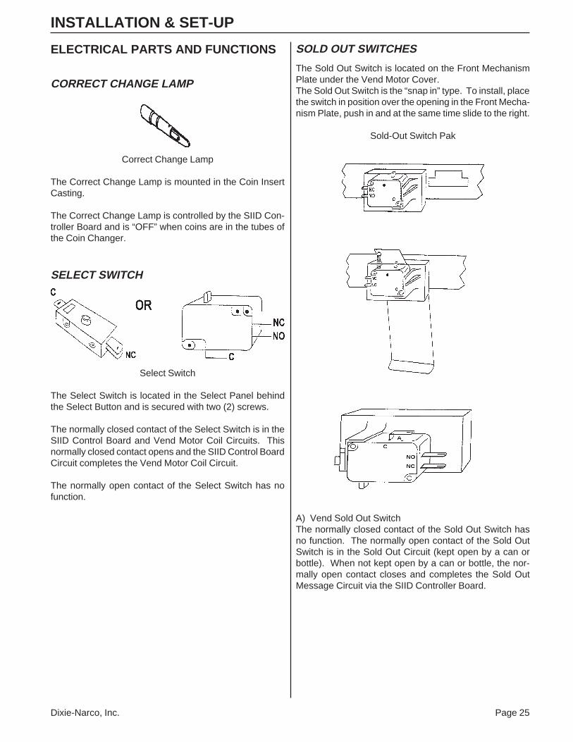
CORRECT CHANGE LAMP
Correct Change Lamp
The Correct Change Lamp is mounted in the Coin InsertCasting.
The Correct Change Lamp is controlled by the SIID Con-troller Board and is “OFF” when coins are in the tubes ofthe Coin Changer.
SELECT SWITCH
Select Switch
The Select Switch is located in the Select Panel behindthe Select Button and is secured with two (2) screws.
The normally closed contact of the Select Switch is in theSIID Control Board and Vend Motor Coil Circuits. Thisnormally closed contact opens and the SIID Control BoardCircuit completes the Vend Motor Coil Circuit.
The normally open contact of the Select Switch has nofunction.
SOLD OUT SWITCHES
The Sold Out Switch is located on the Front MechanismPlate under the Vend Motor Cover.The Sold Out Switch is the “snap in” type. To install, placethe switch in position over the opening in the Front Mecha-nism Plate, push in and at the same time slide to the right.
Sold-Out Switch Pak
A) Vend Sold Out SwitchThe normally closed contact of the Sold Out Switch hasno function. The normally open contact of the Sold OutSwitch is in the Sold Out Circuit (kept open by a can orbottle). When not kept open by a can or bottle, the nor-mally open contact closes and completes the Sold OutMessage Circuit via the SIID Controller Board.
Page 26 Dixie-Narco, Inc.
INSTALLATION & SET-UP
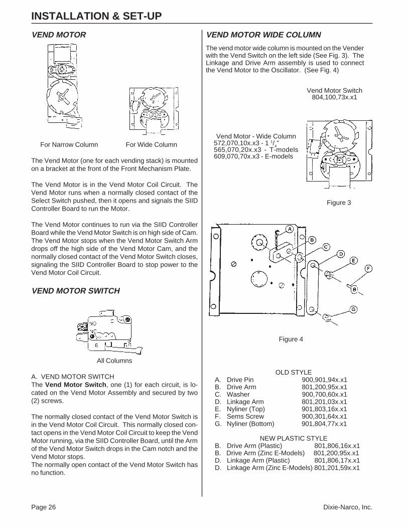
VEND MOTOR
For Narrow Column For Wide Column
The Vend Motor (one for each vending stack) is mountedon a bracket at the front of the Front Mechanism Plate.
The Vend Motor is in the Vend Motor Coil Circuit. TheVend Motor runs when a normally closed contact of theSelect Switch pushed, then it opens and signals the SIIDController Board to run the Motor.
The Vend Motor continues to run via the SIID ControllerBoard while the Vend Motor Switch is on high side of Cam.The Vend Motor stops when the Vend Motor Switch Armdrops off the high side of the Vend Motor Cam, and thenormally closed contact of the Vend Motor Switch closes,signaling the SIID Controller Board to stop power to theVend Motor Coil Circuit.
VEND MOTOR SWITCH
All Columns
A. VEND MOTOR SWITCHThe Vend Motor Switch , one (1) for each circuit, is lo-cated on the Vend Motor Assembly and secured by two(2) screws.
The normally closed contact of the Vend Motor Switch isin the Vend Motor Coil Circuit. This normally closed con-tact opens in the Vend Motor Coil Circuit to keep the VendMotor running, via the SIID Controller Board, until the Armof the Vend Motor Switch drops in the Cam notch and theVend Motor stops.The normally open contact of the Vend Motor Switch hasno function.
VEND MOTOR WIDE COLUMN
The vend motor wide column is mounted on the Venderwith the Vend Switch on the left side (See Fig. 3). TheLinkage and Drive Arm assembly is used to connectthe Vend Motor to the Oscillator. (See Fig. 4)
OLD STYLEA. Drive Pin 900,901,94x.x1B. Drive Arm 801,200,95x.x1C. Washer 900,700,60x.x1D. Linkage Arm 801,201,03x.x1E. Nyliner (Top) 901,803,16x.x1F. Sems Screw 900,301,64x.x1G. Nyliner (Bottom) 901,804,77x.x1
NEW PLASTIC STYLEB. Drive Arm (Plastic) 801,806,16x.x1B. Drive Arm (Zinc E-Models) 801,200,95x.x1D. Linkage Arm (Plastic) 801,806,17x.x1D. Linkage Arm (Zinc E-Models) 801,201,59x.x1
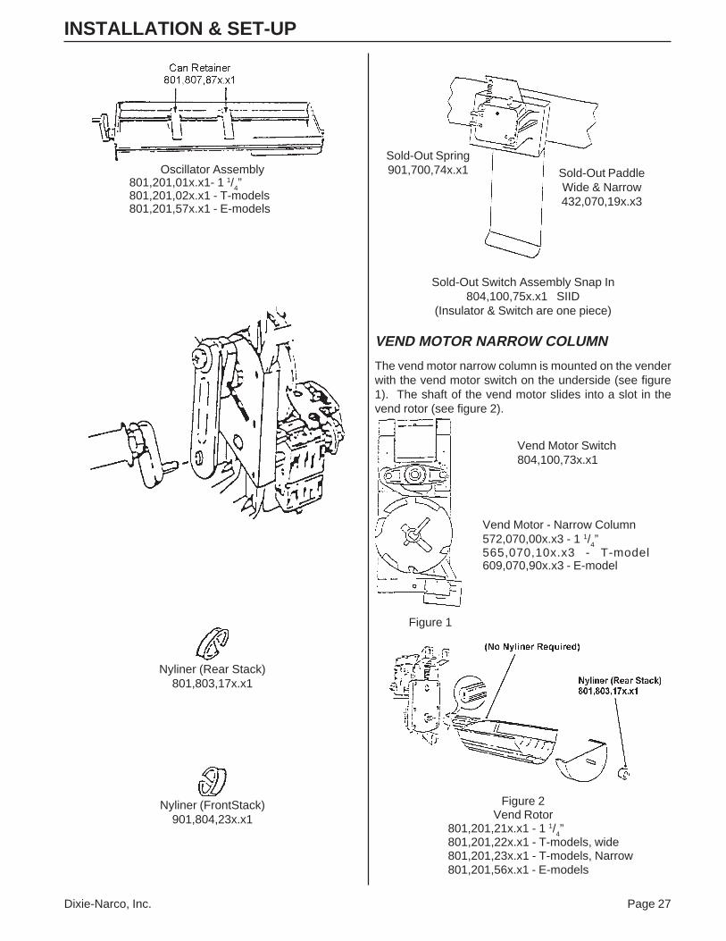
The vend motor narrow column is mounted on the venderwith the vend motor switch on the underside (see figure1). The shaft of the vend motor slides into a slot in thevend rotor (see figure 2).
Refer to the appropriate technical bulletin for proper set-up and vending procedures. Listed are a few of the morewidely used Technical Bulletins relating to shimming.
TB 450 Miscellaneous Worldwide Can Shimming, Shimless Stack Series 90
For E-Model set-ups not listed on the inner door diagram, contact the Dixie-Narco Factory Service Department.
For shimming of venders or products not listed in the above Technical Bulletins call the Dixie-Narco Factory ServiceDepartment or contact your Dixie-Narco Representative.
Dixie-Narco, Inc. Page 29
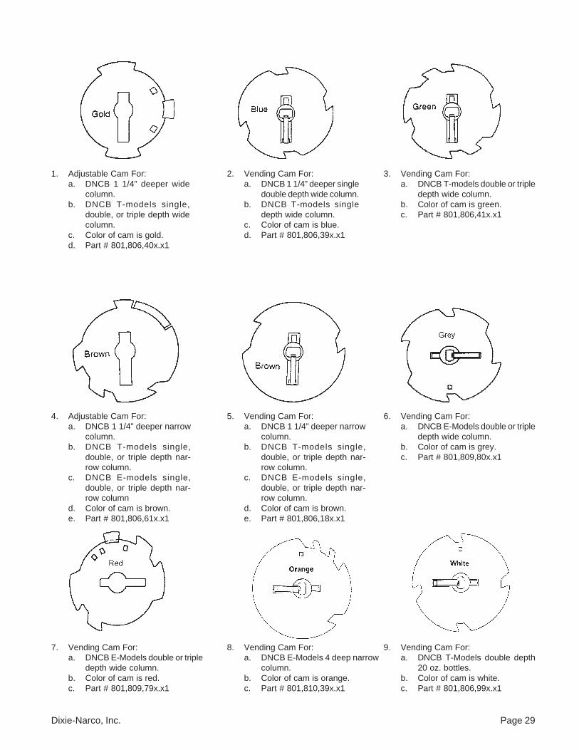
1. Adjustable Cam For:a. DNCB 1 1/4” deeper wide
column.b. DNCB T-models single,
double, or triple depth widecolumn.
c. Color of cam is gold.d. Part # 801,806,40x.x1
2. Vending Cam For:a. DNCB 1 1/4” deeper single
double depth wide column.b. DNCB T-models single
depth wide column.c. Color of cam is blue.d. Part # 801,806,39x.x1
3. Vending Cam For:a. DNCB T-models double or triple
depth wide column.b. Color of cam is green.c. Part # 801,806,41x.x1
c. DNCB E-models single,double, or triple depth nar-row column
d. Color of cam is brown.e. Part # 801,806,61x.x1
5. Vending Cam For:a. DNCB 1 1/4” deeper narrow
column.b. DNCB T-models single,
double, or triple depth nar-row column.
c. DNCB E-models single,double, or triple depth nar-row column.
d. Color of cam is brown.e. Part # 801,806,18x.x1
6. Vending Cam For:a. DNCB E-Models double or triple
depth wide column.b. Color of cam is grey.c. Part # 801,809,80x.x1
7. Vending Cam For:a. DNCB E-Models double or triple
depth wide column.b. Color of cam is red.c. Part # 801,809,79x.x1
8. Vending Cam For:a. DNCB E-Models 4 deep narrow
column.b. Color of cam is orange.c. Part # 801,810,39x.x1
9. Vending Cam For:a. DNCB T-Models double depth
20 oz. bottles.b. Color of cam is white.c. Part # 801,806,99x.x1
Page 30 Dixie-Narco, Inc.
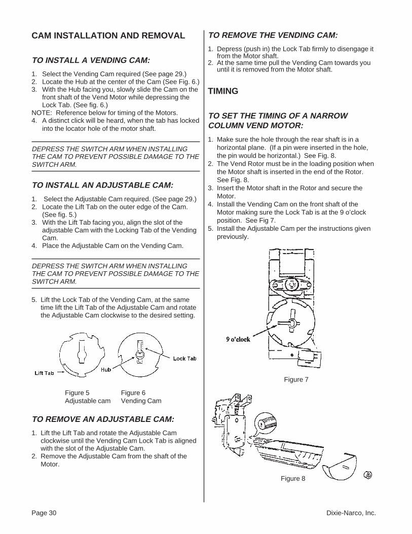
CAM INSTALLATION AND REMOVAL
TO INSTALL A VENDING CAM:
1. Select the Vending Cam required (See page 29.)2. Locate the Hub at the center of the Cam (See Fig. 6.)3. With the Hub facing you, slowly slide the Cam on the
front shaft of the Vend Motor while depressing theLock Tab. (See fig. 6.)
NOTE: Reference below for timing of the Motors.4. A distinct click will be heard, when the tab has locked
into the locator hole of the motor shaft.
DEPRESS THE SWITCH ARM WHEN INSTALLINGTHE CAM TO PREVENT POSSIBLE DAMAGE TO THESWITCH ARM.
TO INSTALL AN ADJUSTABLE CAM:
1. Select the Adjustable Cam required. (See page 29.)2. Locate the Lift Tab on the outer edge of the Cam.
(See fig. 5.)3. With the Lift Tab facing you, align the slot of the
adjustable Cam with the Locking Tab of the VendingCam.
4. Place the Adjustable Cam on the Vending Cam.
DEPRESS THE SWITCH ARM WHEN INSTALLINGTHE CAM TO PREVENT POSSIBLE DAMAGE TO THESWITCH ARM.
5. Lift the Lock Tab of the Vending Cam, at the sametime lift the Lift Tab of the Adjustable Cam and rotatethe Adjustable Cam clockwise to the desired setting.
Figure 5 Figure 6Adjustable cam Vending Cam
TO REMOVE AN ADJUSTABLE CAM:
1. Lift the Lift Tab and rotate the Adjustable Camclockwise until the Vending Cam Lock Tab is alignedwith the slot of the Adjustable Cam.
2. Remove the Adjustable Cam from the shaft of theMotor.
TIMING
TO SET THE TIMING OF A NARROWCOLUMN VEND MOTOR:
1. Make sure the hole through the rear shaft is in ahorizontal plane. (If a pin were inserted in the hole,the pin would be horizontal.) See Fig. 8.
2. The Vend Rotor must be in the loading position whenthe Motor shaft is inserted in the end of the Rotor.See Fig. 8.
3. Insert the Motor shaft in the Rotor and secure theMotor.
4. Install the Vending Cam on the front shaft of theMotor making sure the Lock Tab is at the 9 o’clockposition. See Fig 7.
5. Install the Adjustable Cam per the instructions givenpreviously.
Figure 7
Figure 8
TO REMOVE THE VENDING CAM:
1. Depress (push in) the Lock Tab firmly to disengage itfrom the Motor shaft.
2. At the same time pull the Vending Cam towards youuntil it is removed from the Motor shaft.
Dixie-Narco, Inc. Page 31
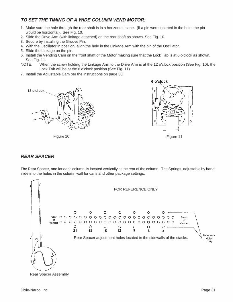
TO SET THE TIMING OF A WIDE COLUMN VEND MOTOR:
1. Make sure the hole through the rear shaft is in a horizontal plane. (If a pin were inserted in the hole, the pinwould be horizontal). See Fig. 10.
2. Slide the Drive Arm (with linkage attached) on the rear shaft as shown. See Fig. 10.3. Secure by installing the Groove Pin.4. With the Oscillator in position, align the hole in the Linkage Arm with the pin of the Oscillator.5. Slide the Linkage on the pin.6. Install the Vending Cam on the front shaft of the Motor making sure that the Lock Tab is at 6 o’clock as shown.
See Fig. 11.NOTE: When the screw holding the Linkage Arm to the Drive Arm is at the 12 o’clock position (See Fig. 10), the
Lock Tab will be at the 6 o’clock position (See Fig. 11).7. Install the Adjustable Cam per the instructions on page 30.
REAR SPACER
The Rear Spacer, one for each column, is located vertically at the rear of the column. The Springs, adjustable by hand,slide into the holes in the column wall for cans and other package settings.
Figure 10 Figure 11
Rear Spacer Assembly
FOR REFERENCE ONLY
Rear Spacer adjustment holes located in the sidewalls of the stacks.
Page 32 Dixie-Narco, Inc.
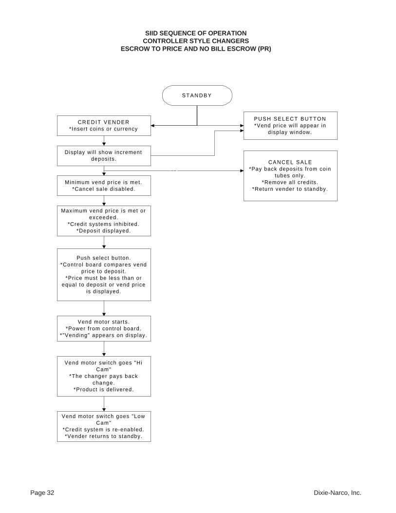
SIID SEQUENCE OF OPERATIONCONTROLLER STYLE CHANGERS
ESCROW TO PRICE AND NO BILL ESCROW (PR)
S T A N D B Y
C R E D I T V E N D E R*Insert coins or currency
P U S H S E L E C T B U T T O N*Vend pr ice wi l l appear in
display window.
Display wi l l show incrementdeposi ts.
Minimum vend pr ice is met.*Cancel sale d isabled.
Maximum vend pr ice is met orexceeded.
*Credit systems inhibi ted.*Deposi t d isplayed.
Push select but ton.*Contro l board compares vend
price to deposit .*Pr ice must be less than or
equal to deposi t or vend pr iceis displayed.
Vend motor star ts.*Power f rom contro l board.
*"Vending" appears on display.
C A N C E L S A L E*Pay back deposi ts f rom coin
tubes only.*Remove al l credi ts.
*Return vender to standby.
Vend motor swi tch goes "LowCam"
*Credi t system is re-enabled.*Vender returns to standby.
––
Vend motor swi tch goes "HiCam"
*The changer pays backchange.
*Product is del ivered.
Dixie-Narco, Inc. Page 33
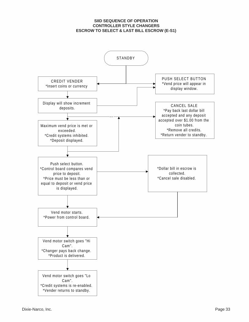
SIID SEQUENCE OF OPERATIONCONTROLLER STYLE CHANGERS
ESCROW TO SELECT & LAST BILL ESCROW (E-S1)
STANDBY
CREDIT VENDER*Insert coins or currency
PUSH SELECT BUTTON*Vend price wil l appear in
display window.
Display wil l show incrementdeposits.
Maximum vend price is met orexceeded.
*Credit systems inhibited.*Deposit displayed.
Push select button.*Control board compares vend
price to deposit.*Price must be less than or
equal to deposit or vend priceis displayed.
Vend motor starts.*Power from control board.
CANCEL SALE*Pay back last dollar bil l
accepted and any depositaccepted over $1.00 from the
coin tubes.*Remove all credits.
*Return vender to standby.
Vend motor switch goes "HiCam".
*Changer pays back change.*Product is delivered.
––
Vend motor switch goes "LoCam".
*Credit systems is re-enabled.*Vender returns to standby.
*Dollar bil l in escrow iscollected.
*Cancel sale disabled.
Page 34 Dixie-Narco, Inc.
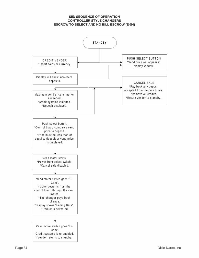
SIID SEQUENCE OF OPERATIONCONTROLLER STYLE CHANGERS
ESCROW TO SELECT AND NO BILL ESCROW (E-S4)
S T A N D B Y
CREDIT VENDER*Insert coins or currency
PUSH SELECT BUTTON*Vend price wil l appear in
display window.
Display wil l show incrementdeposits.
Maximum vend pr ice is met orexceeded.
*Credit systems inhibited.*Deposit displayed.
Push select button.*Control board compares vend
price to deposit.*Price must be less than or
equal to deposit or vend priceis displayed.
Vend motor starts.*Power from select switch.
*Cancel sale disabled.
CANCEL SALE*Pay back any deposit
accepted from the coin tubes.*Remove al l credits.
*Return vender to standby.
Vend motor switch goes "HiCam".
*Motor power is from thecontrol board through the vend
switch.*The changer pays back
change.*Display shows "Fall ing Bars".
*Product is del ivered.
––
Vend motor switch goes "LoCam".
*Credit systems is re-enabled.*Vender returns to standby.
Dixie-Narco, Inc. Page 35
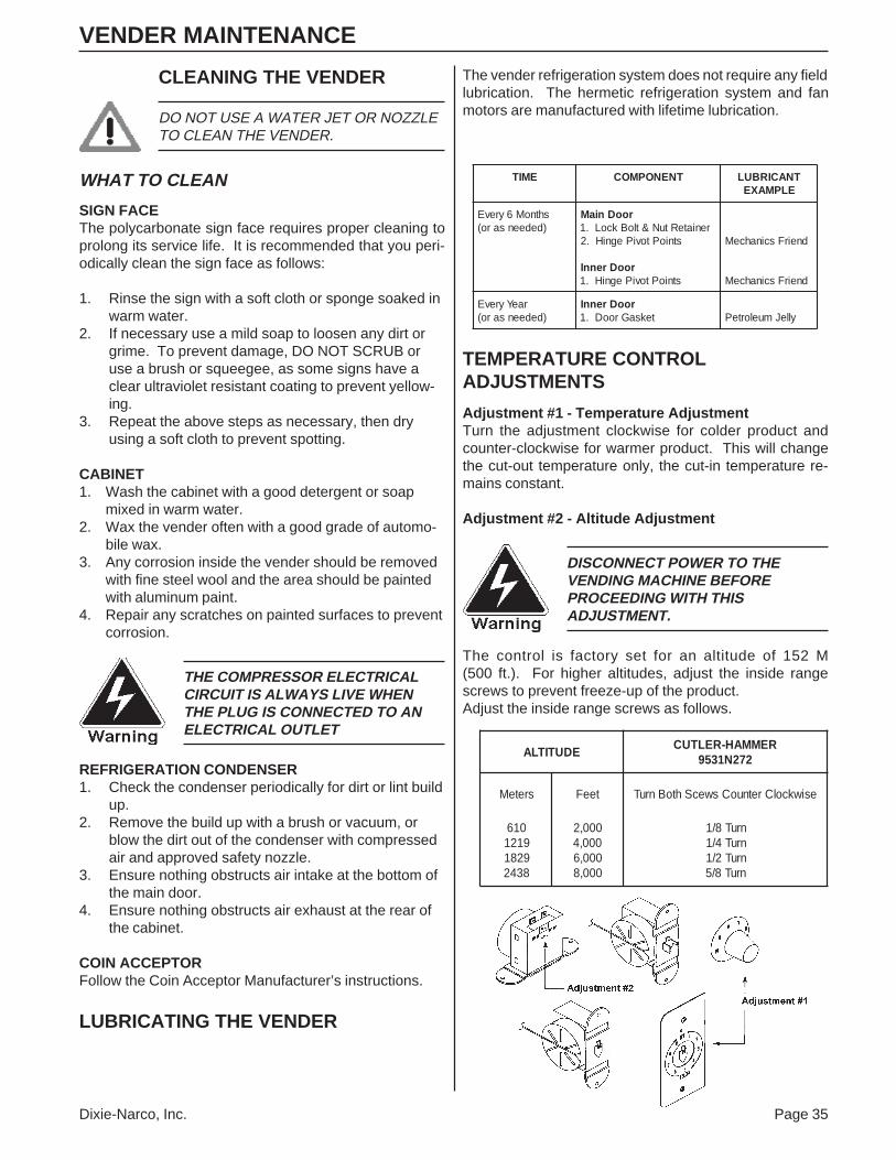
VENDER MAINTENANCE
CLEANING THE VENDER
DO NOT USE A WATER JET OR NOZZLETO CLEAN THE VENDER.
WHAT TO CLEAN
SIGN FACEThe polycarbonate sign face requires proper cleaning toprolong its service life. It is recommended that you peri-odically clean the sign face as follows:
1. Rinse the sign with a soft cloth or sponge soaked inwarm water.
2. If necessary use a mild soap to loosen any dirt orgrime. To prevent damage, DO NOT SCRUB oruse a brush or squeegee, as some signs have aclear ultraviolet resistant coating to prevent yellow-ing.
3. Repeat the above steps as necessary, then dryusing a soft cloth to prevent spotting.
CABINET1. Wash the cabinet with a good detergent or soap
mixed in warm water.2. Wax the vender often with a good grade of automo-
bile wax.3. Any corrosion inside the vender should be removed
with fine steel wool and the area should be paintedwith aluminum paint.
4. Repair any scratches on painted surfaces to preventcorrosion.
THE COMPRESSOR ELECTRICALCIRCUIT IS ALWAYS LIVE WHENTHE PLUG IS CONNECTED TO ANELECTRICAL OUTLET
REFRIGERATION CONDENSER1. Check the condenser periodically for dirt or lint build
up.2. Remove the build up with a brush or vacuum, or
blow the dirt out of the condenser with compressedair and approved safety nozzle.
3. Ensure nothing obstructs air intake at the bottom ofthe main door.
4. Ensure nothing obstructs air exhaust at the rear ofthe cabinet.
COIN ACCEPTORFollow the Coin Acceptor Manufacturer’s instructions.
LUBRICATING THE VENDER
The vender refrigeration system does not require any fieldlubrication. The hermetic refrigeration system and fanmotors are manufactured with lifetime lubrication.
EMIT TNENOPMOC TNACIRBULELPMAXE
shtnoM6yrevE)dedeensaro(
rooDniaMreniateRtuN&tloBkcoL.1
stnioPtoviPegniH.2
rooDrennIstnioPtoviPegniH.1
dneirFscinahceM
dneirFscinahceM
raeYyrevE)dedeensaro(
rooDrennIteksaGrooD.1 ylleJmuelorteP
TEMPERATURE CONTROLADJUSTMENTS
Adjustment #1 - Temperature AdjustmentTurn the adjustment clockwise for colder product andcounter-clockwise for warmer product. This will changethe cut-out temperature only, the cut-in temperature re-mains constant.
Adjustment #2 - Altitude Adjustment
DISCONNECT POWER TO THEVENDING MACHINE BEFOREPROCEEDING WITH THISADJUSTMENT.
The control is factory set for an altitude of 152 M(500 ft.). For higher altitudes, adjust the inside rangescrews to prevent freeze-up of the product.Adjust the inside range screws as follows.
EDUTITLAREMMAH-RELTUC
272N1359
sreteM teeF esiwkcolCretnuoCswecShtoBnruT
016912192818342
000,2000,4000,6000,8
nruT8/1nruT4/1nruT2/1nruT8/5
Page 36 Dixie-Narco, Inc.
Che
ck w
irin
g to
SII
D.
Sel
ect
harn
ess
plug
ged
into
sel
ect
pane
l co
nnec
tor.
Che
ck P
4 fo
r a
ben
t pi
n.O
.K.?
Rep
air
pin.
Mak
e su
re n
ot t
ore
-ben
d pi
n.P
ower
ven
der
back
up.
Ret
est
vend
er a
ndre
turn
to
serv
ice.
Doe
s D
ispl
ay s
till
show
1-1
?
No
Ye
s
Che
ck c
onti
nuit
y o
f en
able
lin
esP
4-12
& P
4-13
sw
itch
es.
O.K
.?
Ye
s
Che
ck P
4 fo
r al
lse
lect
sw
itch
wir
ing.
O.K
.?Y
es
No
Rep
air
grou
nd w
ire.
Rep
air
wir
ing.
No
Cal
l D
ixie
-Nar
coF
acto
ry S
ervi
ce.
Ye
s
Pow
er v
ende
r do
wn.
No
Sel
ect P
anel
Tro
uble
shoo
ting
Cha
rtP
robl
em:
Whe
n ve
nder
pow
ers
up, 1
-1 s
crol
ls o
n th
e di
spla
y
Dixie-Narco, Inc. Page 37
Sel
ect P
anel
Pro
blem
sP
robl
em:
Can
not e
nter
men
u or
dia
gnos
tics
men
u.
Che
ck d
oor
switc
h w
irin
g.O
.K.?
Che
ck d
oor
swit
chfo
r pr
oper
pos
ition
.O
.K.?
Che
ck d
oor
switc
h co
ntin
uity
.O
.K.?
Che
ck s
wit
chgr
ound
wir
e fo
rco
ntin
uity
.O
.K.?
Rep
air
door
sw
itch
wir
ing.
Put
doo
r sw
itch
in p
rope
rpo
sitio
n.(C
heat
er s
witc
h po
sitio
n.)
Rep
air
door
sw
itch.
Rep
air
grou
nd w
ire.
No
No
Yes
Yes
Yes
No
No
Yes
Rep
air
conn
ecto
r.
Che
ck P
4co
nnec
tor
for
bent
pin
s.O
.K.?
No
Yes
Che
ck c
ontin
uity
from
doo
r sw
itch
to
P4.
O
.K.?
Yes
Cal
l Dix
ie-N
arco
Fact
ory
Ser
vice
.R
epai
r w
irin
g.N
o
Pow
er v
ende
r do
wn.
Page 38 Dixie-Narco, Inc.
Sel
ect P
anel
Pro
blem
sP
robl
em:
1 or
mor
e sw
itche
s no
t fun
ctio
nal.
En
ter
dia
gn
ost
ic m
en
u.
Pre
ss s
ele
ct b
utt
on
un
til
you
fin
d t
he
pro
ble
m.
Re
pa
ir w
irin
ga
nd
re
test
.
Re
pa
ir b
en
t p
ina
nd
re
test
.
Is p
rob
lem
swit
ch s
tuck
?Y
es
Re
pa
ir o
bst
ruct
ion
an
d r
ete
st.
No
No
No
Ca
ll D
ixie
-Na
rco
Fa
cto
ry S
erv
ice
Ch
eck
co
nti
nu
ity
of
swit
ch.
O.K
.?
Ch
eck
wir
ing
con
tin
uit
y to
SII
D b
oa
rd.
O.K
.?
Ch
eck
fo
r b
en
t p
inin
P4
co
nn
ect
or.
O.K
.?
Ye
s
Ye
s
Ye
s
Re
pla
ce s
wit
cha
nd
re
test
.
No
Dixie-Narco, Inc. Page 39
Sol
d-O
ut S
witc
h P
robl
emP
robl
em:
Ven
der
will
not
rec
ogni
ze a
sol
d-ou
t col
umn.
Ent
er d
iagn
ostic
s m
enu
and
adva
nce
to "
Su"
.
Sol
d-ou
tsw
itche
s ar
eno
t w
orki
ng?
No
Yes
Det
erm
ine
whi
ch s
witc
his
not
wor
king
with
diag
nost
ics.
Are
all
switc
hes
plug
ged
in?
Yes
No
Plu
g sw
itche
s in
.
Is h
arne
sspl
ugge
d in
toex
tens
ion
cabl
e?N
oP
lug
harn
ess
in.
Yes
Are
all
switc
hes
wir
ed t
o N
.O.?
Yes
No
Rew
ire
switc
hes.
Che
ck c
ontin
uity
of g
roun
d w
ire t
o bo
ard.
O.K
.?
Yes
Cal
l Dix
ie-N
arco
Fac
tory
Ser
vice
.
No
Rep
air
switc
hha
rnes
s.Is
bre
ak in
gro
und
onex
tens
ion
harn
ess?
No
Rep
air
exte
nsio
n ha
rnes
s.
Che
ck f
or b
ent
pin
in P
5 co
nnec
tor.
O.K
.?Y
es
NoY
es
Rep
air
bent
pin
and
ret
est.
Is s
witc
hpl
ugge
d in
?
Rep
air
wiri
ng.
Rep
air
wiri
nger
ror.
Rep
lace
switc
h.
Rep
air
grou
nd w
ire.
Yes
Is s
witc
h m
is-
wir
ed?
No
Che
ckco
ntin
uity
toS
IID
Boa
rd.
O.K
?
No
Yes
Che
ck c
ontin
uity
of s
witc
h. O
.K.?
No
Yes
Is g
roun
dw
ire o
n sw
itch
O.K
.?N
o
Yes
Yes
Page 40 Dixie-Narco, Inc.
Not
e A
ccep
tor
Tro
uble
shoo
ting
US
A L
ow L
evel
Pro
blem
: A
ccep
tor
will
not
take
not
es o
r do
es n
ot d
ispl
ay th
em.
Mak
e su
re v
end
pric
esar
e no
t set
to z
ero.
Is v
ende
r in
exac
t ch
ange
?Y
esN
oTa
ke v
ende
r ou
t of
exac
t ch
ange
.
Ent
er d
iagn
ostic
san
d sc
roll
to "
NA
".
Doe
s "N
A"
flash
ing
light
sco
me
on?
Che
ck 1
Ape
riph
eral
fus
e.O
.K.?
No
No
Yes
Yes
Will
US
Aac
cept
$1.
00an
d di
spla
y it?
No
Yes
Rep
lace
US
A w
ithkn
own
good
uni
t.
Exi
t m
enu
and
retu
rnto
idle
mod
e.
Do
1 co
rrec
t ch
ange
vend
.
TO
B(o
n ne
xt p
age)
Ret
urn
vend
erto
ser
vice
.H
as p
robl
embe
en s
olve
d?
No
Yes
Rep
lace
US
A.
Doe
s U
SA
wor
k?
Yes
No
Che
ck h
arne
ss.
O.K
.?
YesNo
Rep
lace
SII
Dpa
ckag
e.
Rep
lace
har
ness
.
Che
ck n
ote
acce
ptor
har
ness
for
cont
inui
ty.
O.K
.?
No
Yes
Rep
lace
US
Aw
ith k
now
ngo
od u
nit.
O.K
.?
N
Yes
Rep
lace
US
A.
Dixie-Narco, Inc. Page 41
Not
e A
ccep
tor
Tro
uble
shoo
ting
US
A L
ow L
evel
Pro
blem
: A
ccep
tor
will
not
taek
not
es o
r do
es n
ot d
ispl
ay th
em.
B
Ch
an
ge
co
in m
ec
h t
ok
no
wn
go
od
un
it.
Fil
l c
oin
tu
be
s,
5 c
en
ts,
10
ce
nts
, 2
5 c
en
ts
Do
1 e
xa
ct
ch
an
ge
ve
nd
.
Re
tes
t n
ote
ac
ce
pto
r. O
.K.?
Ye
s
Re
pla
ce
co
in m
ec
h a
nd
rete
st
No
Re
pla
ce
SII
D p
ac
ka
ge
.
Page 42 Dixie-Narco, Inc.
Not
e A
ccep
tor
Tro
uble
shoo
ting
Mar
s V
FM
1 or
VF
M3
Low
Lev
el A
ccep
tor
Pro
blem
: N
ote
acce
ptor
will
not
acc
ept m
oney
; or
take
s no
te a
nd d
oes
not d
ispl
ay c
redi
t.
Mak
e su
re a
ll ve
nd p
rice
s ar
e no
t se
tto
zer
o.
Is v
ende
r in
exac
t ch
ange
?Y
esTa
ke v
ende
r ou
t of
exa
ctch
ange
.
Doe
s ve
nder
hav
epr
oper
har
ness
es?
No
Mar
s ha
rnes
s #0
1-12
-065
-4 a
ndD
ixie
Har
ness
2x6
136
(804
,909
,720
.01)
No
Yes
Ent
er d
iagn
ostic
s m
enu
and
adva
nce
to "
NA
".
Will
not
e ac
cept
or t
ake
a no
tean
d di
spla
y it?
No
Che
ck 1
Ape
riph
eral
fus
e.O
.K.?
Yes
Che
ck w
irin
gco
ntin
uity
.O
.K.?
Yes
Rep
lace
with
know
n go
odva
lidat
or.
Cal
l Dix
ie-
Nar
co F
acto
ryS
ervi
ce.
Yes
Che
ck v
end
pric
esov
er $
1.00
. O
.K.?
No
Che
ck c
oin
mec
hw
ith k
now
n go
odm
ech.
O.K
.?N
o
Yes
Rep
lace
coi
nm
ech.
Red
uce
pric
es t
o$1
.00.
Yes
Dixie-Narco, Inc. Page 43
Hig
h Le
vel N
ote
Acc
epto
r T
roub
lesh
ootin
g (A
ll A
ccep
tors
)P
robl
em:
Not
e ac
cept
or w
ill n
ot ta
ke n
ote
or d
ispl
ay c
redi
t whe
n it
does
take
not
e.
AE
nter
dia
gnos
tics
and
adva
nce
to "
NA
".
Pre
ss b
utto
n 1.
Doe
s di
spla
yin
dica
te "
HL"
?N
oY
esIs
acc
epto
rpl
ugge
d in
?
No
Plu
g ac
cept
or in
.C
lose
doo
r.
Mak
e su
re a
ll ve
ndpr
ices
are
not
zer
o.
Inse
rt n
ote
inac
cept
or.
Doe
sac
cept
or t
ake
note
?
Did
cre
dit
regi
ster
on d
ispl
ay?
Yes
No
Yes
Che
ck c
ontin
uity
of h
arne
ss.
O.K
.?R
epla
ce h
arne
ss.
No
Aab
ove
Yes
To C
(on
next
pag
e)Y
es
Rep
lace
acc
epto
rw
ith k
now
n go
odun
it. O
.K.?
No
To B
(on
next
pag
e)
Yes
Rep
lace
acce
ptor
.
No
Page 44 Dixie-Narco, Inc.
Hig
h Le
vel N
ote
Acc
epto
r T
roub
lesh
ootin
g (A
ll A
ccep
tors
)P
robl
em:
Not
e ac
cept
or w
ill n
ot ta
ke n
ote
or d
ispl
ay c
redi
t whe
n it
does
take
not
e.
CB
To A
(on
prev
ious
pag
e)
Exi
t di
agno
stic
men
u an
dre
turn
to id
le m
ode.
Inse
rt n
ote
in n
ote
acce
ptor
. Is
prob
lem
sol
ved?
Ret
urn
vend
er t
o se
rvic
e.
Yes
Rep
lace
SII
D c
ontr
ol a
ssy.
Che
ck la
mp
fuse
.O
.K.?
Yes
Rep
lace
fus
e.N
o
Do
one
exac
t ch
ange
ven
d.
Put
mor
e ch
ange
in c
oin
mec
h.Is
exa
ct c
hang
e lig
ht o
n?N
o
Yes
No
Ret
est
not
acce
ptor
. O
.Y
es
No
Rep
lace
coi
nan
d fil
l coi
n t
Do
one
exac
tch
ange
ven
d.R
etes
t no
teac
cept
or.
O.K
.?
Yes
No
Cal
l Dix
ie-N
arco
Fact
ory
Ser
vice
.
Dixie-Narco, Inc. Page 45
Mul
tidro
p C
oin
Mec
h / N
ote
Acc
epto
r T
roub
lesh
ootin
gP
robl
em:
Not
e ac
cept
or w
ill n
ot a
ccep
t coi
ns, a
nd th
e ex
act c
hang
e lig
ht is
off.
Is e
xact
cha
nge
lam
pon
?
Yes
Ent
er d
iagn
ostic
s m
ode
and
adva
nce
to "
CM
"
No
Ent
er "
DS
P"
indi
agno
stic
s an
d te
st.
Dis
play
seg
men
ts li
ght.
No
Rep
lace
dis
play
boa
rd.
See
if c
oin
optio
n is
reco
gniz
ed a
s "M
DB
".E
xit
"CN
" m
ode.
Adv
ance
to
"NA
" N
ote
Acc
epto
r te
st.
To A
(on
next
pag
e)
Page 46 Dixie-Narco, Inc.
Mul
tidro
p C
oin
Mec
h / N
ote
Acc
epto
r T
roub
lesh
ootin
gP
robl
em:
Not
e ac
cept
or w
ill n
ot a
ccep
t coi
ns, a
nd th
e ex
act c
hang
e lig
ht is
off.
AP
ress
but
ton
1.D
oes
mes
sage
disp
lay
"MD
B"?
No
Yes
Is n
ote
acce
ptor
plug
ged
in?
No
Plu
g ac
cept
or in
.
Yes
Rep
lace
har
ness
.
Inse
rt n
ote
inac
cept
or.
Doe
sac
cept
or a
ccep
tno
te?
No
Yes
Che
ck c
ontin
uity
of h
arne
ss.
O.K
.?N
o
Ret
urn
to A
(on
this
pag
e)
Yes
Rep
lace
acc
epto
r w
ith
know
n go
od u
nit.
Doe
s cr
edit
show
on d
ispl
ay?
No
Ret
urn
vend
er t
o id
lem
ode.
Yes
Fill
up c
oin
mec
h w
ithdi
mes
, ni
ckel
s, &
quar
ters
.
Has
pro
blem
gone
aw
ay?
No
Is c
oin
mec
hfu
ll of
cha
nge?
Yes
No
Yes
Do
1 ex
act
chan
geve
nd.
Ret
est
note
acce
ptor
. H
aspr
oble
m g
one
away
?
Yes
Cal
l Dix
ie-N
arco
Fac
tory
Ser
vice
.
Ret
urn
vend
er t
ose
rvic
e.
Dixie-Narco, Inc. Page 47
Coi
n M
ech
Tro
uble
shoo
ting
MC
-500
0 M
icro
Mec
hs (
All
Coi
n M
echs
)A
- C
oin
Mec
h ac
cept
ed c
oins
, but
will
not
dis
pens
e th
em.
1E
nter
ser
vice
mod
ean
d ad
vanc
e to
"C
-D".
Exi
t se
rvic
e m
enu
& e
nter
diag
nost
ics
& a
dvan
ce t
o"C
N".
Dep
ress
but
ton
1.D
id m
ech
disp
ense
a co
in?
Yes
No
Inse
rt 1
qua
rter
, di
me,
&ni
ckel
int
o co
in m
ech.
Che
ck c
oin
mec
h ha
rnes
sfo
r co
ntin
uity
.Y
es
Che
ck F
3 1
Am
p fu
se.
Is f
use
O.K
.?N
oR
epla
ce 1
Am
p fu
se.
Is h
arne
ss O
.K.?
Yes
No
Rep
lace
coi
n m
ech
harn
ess.
Che
ck c
oin
mec
h w
ith
know
ngo
od m
ech.
Doe
s m
ech
func
tion
prop
erly
?
Pre
ss b
utto
n 2.
Did
mec
h di
spen
seal
l coi
ns?
Yes
Exi
t di
agno
stic
s m
enu
and
ente
r st
andb
y m
ode.
No
Rep
lace
coi
n m
ech.
Yes
No
Pla
ce e
noug
h co
ins
in m
ech
to m
ake
chan
ge a
fter
ave
nd.
Did
mec
hdi
spen
se c
oins
?N
o
Yes
Cal
l D
ixie
-Nar
co F
acto
ryS
ervi
ce.
Pro
blem
res
olve
d.
Ret
urn
to 1
abo
ve.
Page 48 Dixie-Narco, Inc.
Coi
n M
ech
Tro
uble
shoo
ting
L+/M
C50
00 (
Mic
ro M
ech)
Inte
rfac
e P
robl
ems
A -
Not
acc
eptin
g M
oney
B -
Not
dis
play
ing
cred
it.A
Mak
e su
re c
oin
mec
h is
plug
ged
in.
Ent
er d
iagn
osti
cs.
2 B
Adv
ance
to
"CN
" fo
rco
in m
ech
test
.
Coi
n m
ech
reco
gniz
edas
"M
M"
(mic
ro m
ech)
.N
oC
heck
for
pro
per
coin
mec
h.
Yes
Che
ck F
3 fu
se.
O.K
.?R
epla
ce f
use.
Inse
rt c
oins
in
mec
h. D
id m
ech
acce
pt c
oins
?N
o
Yes
No
1
Did
dis
play
regi
ster
cre
dit?
Yes
Ent
er s
ervi
ce m
ode
and
adva
nce
to "
S-P
".
Yes
Che
ck c
oin
mec
hha
rnes
s fo
r co
ntin
uity
.N
oY
es
Har
ness
chec
k ou
t.O
.K.?
No
Rep
lace
har
ness
.R
etur
n to
1(a
bove
)
Har
ness
chec
k ou
t.O
.K.?
No
Yes
Che
ck c
oin
mec
hw
ith
know
n go
od m
ech.
Doe
s m
ech
func
tion
prop
erly
?
No
Cal
l D
ixie
-Nar
co f
acto
ryS
ervi
ce.
3
Ret
urn
to 2
(abo
ve)
Cha
nge
pric
es.
Are
all
vend
pri
ces
set
to 0
?
Yes
No
3
Che
ck c
oin
mec
hex
tens
ion
harn
ess.
Yes
Dixie-Narco, Inc. Page 49
Coi
n M
ech
Tro
uble
shoo
ting
MC
-500
0 (M
icro
Mec
h) In
terf
ace
Mak
a O
nly.
Pro
blem
: M
ech
will
not
acc
ept c
oins
.
Scr
oll t
o "S
-P".
Set
-pri
ce.
A
Are
pri
ces
set
to z
ero?
Yes
Res
et v
end
pric
es.
Ent
er D
iagn
ostic
s
No
Scr
oll t
o co
inm
ech
test
"C
M" .
Inse
rt 1
qua
rter
, n
icke
l, &
dim
e.D
oes
mec
hac
cept
coi
ns?
Yes
No
Che
ck c
ontin
uity
of c
oin
mec
hha
rnes
s. O
.K.?
Yes
No
Ret
urn
to A
(abo
ve)
Did
cre
dit r
egis
ter
on d
ispl
ay?
No
Yes
Ret
urn
vend
erto
ser
vice
.
Rep
lace
def
ectiv
eha
rnes
s.C
heck
F3
1 A
mp
fuse
. O
.K.?
Yes
Ret
urn
to B
(nex
t pa
ge)
No
Rep
lace
fus
e F3
1 A
mp.
Ret
urn
to A
(abo
ve)
Page 50 Dixie-Narco, Inc.
Coi
n M
ech
Tro
uble
shoo
ting
MC
-500
0 (M
icro
Mec
h) In
terf
ace
Mak
a O
nly.
Pro
blem
: M
ech
will
not
acc
ept c
oins
.
B
Rep
lace
coi
n m
ech
with
kno
wn
good
mec
h.
Doe
s ne
w m
ech
acce
pt &
dis
play
coin
s?
No
Cal
l Dix
ie-N
arco
Fact
ory
Ser
vice
.
Yes
Rep
lace
coi
n m
ech.
Dixie-Narco, Inc. Page 51
Mul
tidro
p C
oin
Mec
h T
roub
lesh
ootin
gP
robl
em:
Mec
h w
ill n
ot a
ccep
t coi
ns.
Mec
h w
ill n
ot a
ccep
t co
ins.
Mak
e S
ure
coin
mec
h is
plug
ged
in.
Adv
ance
to
"S-P
"se
t-pr
ice.
Che
ck p
rice
s.A
re p
rice
s se
tto
zer
o.
Yes
No
Res
et v
end
pric
es.
Ent
er d
iagn
ostic
sm
enu.
A
Scr
oll t
o co
inm
ech
test
"C
M".
Inse
rt 1
qua
rter
, d
ime
& N
icke
l. D
idm
ech
acce
pt c
oins
?Y
es
No
Ret
urn
to B
(on
next
pag
e)
Did
cre
dit
appe
aron
the
dis
play
?
No
Ret
urn
to A
(abo
ve)
Yes
Page 52 Dixie-Narco, Inc.
Mul
tidro
p C
oin
Mec
h T
roub
lesh
ootin
gP
robl
em:
Mec
h w
ill n
ot a
ccep
t coi
ns.
B
Che
ck c
ontin
uity
of h
arne
ss.
O.K
.?N
o
Yes
Rep
lace
coi
n m
ech
harn
ess.
Ret
urn
to A
(on
prev
ious
pag
e)
Che
ck c
oin
mec
hw
ith k
now
n go
od m
ech.
Ret
est
coin
mec
h.O
.K.?
No
Yes
Rep
lace
coi
n m
ech.
Cal
l Dix
ie-N
arco
Fact
ory
Ser
vice
.
Dixie-Narco, Inc. Page 53
TROUBLESHOOTING EXAMPLES
SIID VENDING
1. Problem: Free vend on one column.Troubleshooting:
A) Check selection price.B) Check for bad connections or broken, backed out, or crossed wires from vend motor to control board.C) Check for sticking select button.D) Check control board.
2. Problem: One motor continues to home with door closed, shows “JC#” when in diagnostics.Troubleshooting:
A) If using Mars Validator, ensure correct interface harness is used.B) Check for bad connections or broken, backed out, or crossed wires from vend motor to control board.
(Note: Check wires on left side of vend motor cover.)C) Check vend switch.D) Check control board.
3. Problem: One column sold out, but still vends.Troubleshooting:
A) Check sold-out switch.B) Check for bad connections or broken, backed out, or crossed wires from sold-out switch to control board.
(Note: Check wires on left side of vend motor cover.)
4. Problem: Vender will not sequence (Coca-Cola only).Troubleshooting:
A) Ensure wire #24 is in select panel harness and is in correct pin location.B) Check for bad connection or broken wire #24 in select panel harness.C) Make sure wire #24 is in correct location.D) Check control board.
5. Problem: Free vend on one or more columns.Troubleshooting:
A) Check secondary pricing program.B) Check for bad connections or broken, backed out, or crossed wires from vend motor to control board.C) Check for sticking select button.D) Check for bad vend motor switch.E) Check control board.
6. Problem: Column Jackpots.Troubleshooting:
A) Check problem column(s) in motor test.B) Check motor for:
1. Syrup on brake.2. Locate/check brake spring.3. Check motor switch.
C) Check wiring from/to motor switch of problem column.D) Check wiring at mate-n-lock on cabinet harness and cabinet extension harness.E) Check motor.F) Check control board.
Page 54 Dixie-Narco, Inc.
7. Problem: Column will not vend.Troubleshooting:
A) Go to diagnostics and test.B) Check for bad connection or broken, backed out, or crossed wires.(Also check ballast wires).
8. Problem: Motor stops on high cam.Troubleshooting:
A) Change vend switch.B) Install current software.
-5 or 380.11 or greater two-button programming.-3.16 or 390.11 or greater four button programming.
9. Problem: No motors work.Troubleshooting:
A) Check F2 motor power fuse (6 Amp).B) Check lamp and lamp wiring for broken, backed out, or crossed wires.C) Check ballast and ballast wiring for broken, backed out, or crossed wires.
10. Problem: F2 motor power fuse continuously blows.Troubleshooting:
A) Check if 6 amp fuse is used.B) Check that capacitor instead of MOV used at CR1 location.C) Check ohms of each motor in off state
- unplug wires to coil of motor.- ohms should be 6.5, if less coil of motor has a short.
D) Check motor harness.E) Check motor extension harness.F) Check for bad bulb in lighting system.
SIID COIN / CURRENCY
1. Problem: Will not accept coins or bills.Troubleshooting:
A) Check coin return lever is not pressed.B) Check F3 peripheral (1.0 Amp) fuse.C) Go to diagnostics and test.
1. Will not take coins, replace coin mech.2. Still will not take coins, check connections and mech harness.
D) Check for bad connections or broken, backed out, or crossed wires from validator/changer to control board.E) With Mars 6510 Mdb mechs, serialized prior to 176xxxxxxxx that do not have a red dot on the coin mech,
check the coin mech.F) Check control board.
2. Problem: Validator sometimes sets up credit and then steals bill.Troubleshooting:
A) Check for proper interface harness.B) Check for bad connections or broken, backed out, or crossed wires from vend/sold-out harness.C) Check validator.D) Check control board.
3. Problem: Accepts coins and displays, but will not vend.Troubleshooting:
A) Check coin mech.B) Check for bad connections or broken, backed out, or crossed wires from validator/changer to control board.C) Check voltage supply (110-115AC) at outlet.D) Check control board.
5. Problem: Cannot dump coins when in “Cd” mode.Troubleshooting:
A) Check for bad connections or broken, backed out, or crossed wires from changer to control board.B) Check select switches and wiring.C) Check coin mech.D) Ensure you are not using Mars International Executive or NRI Simplex changers.E) Check voltage supply (110-115AC) at outlet.F) Check control board.
6. Problem: BA30 stealing bills.Troubleshooting:
A) Check door switch.B) Check validator.C) Check interface harness.
7. Problem: Want to install a debit card system.Troubleshooting:
A) Need to contact card system supplier for details.
8. Problem: $1 and $5 Bill Acceptance (Black label box 2 button programming)Troubleshooting:
A) Works with1. BA-302. VFM-3 Low Level3. DBA -2 or 3
9. Problem: $1 and $5 Bill Acceptance (Red label box 4 button programming)Troubleshooting:
A) Works with1. BA-30 Mdb2. Mars VN 2500 Series Mdb
10. Problem: Install bill, unplug vender, plug in vender, gives $1 credit and bill back.Troubleshooting:
A) Set Escrow to “Pr” or “ES-4”B) Install current software.
-5 or 380.11 or greater two-button programming.-3.16 or 390.11 or greater four-button programming.
A) Check limited access program.B) Check for crossed wires in cabinet harness and cabinet extension harness or loose wire harness connec-
tion.C) Check for motors rubbing motor cover (on early SIID venders).
2. Problem: Sold-out message comes on with product in column.Troubleshooting:
A) Check programming and ensure limited access is not on.B) Check for bad connections or broken, backed out, or crossed wires from select switch to control board.(Note: Check wires on left side of motor cover.)C) Check for motor rubbing motor cover (on early SIID venders).
3. Problem: Sold-out switches work the incorrect column.Troubleshooting:
A) Ensure correct cabinet harness and select harness are being used.B) Check for crossed wires in cabinet harness or cabinet extension harness.
Dixie-Narco, Inc. Page 57
SIID SELECT PANEL / DISPLAY1. Problem: Plug in vender and displays a blank or “rrrr” appears on the display; vender will not function.Troubleshooting:
A) Press a select button to change message on display; this should clear “RRRR”s.B) Remove power to vender for one minute, then power vender back up.C) Check main power plug for loose connection.D) Check for bad connections or broken wires from display to control board.E) Check display board.F) Check control board.
2. Problem: Display will not function.Troubleshooting:
A) Check for bad connections or broken wires from display to control board.B) Check F1 motor power fuse (1.6 Amp).C) Check display board.D) Check transformer.E) Check control board.
3. Problem: Display shows $1 and then increases in dollar increments.Troubleshooting:
A) Check coin mech.B) Check validator.C) Check control board.
4. Problem: Cannot set price on a given selection.Troubleshooting:
A) Check for bad connections or broken wires from select switch to control board.B) Check select switches.C) Check control board.
5. Problem: Vender changes a set vend price to .10¢ on selections on its own. (domestic only - .10¢ could be anygiven price).
Troubleshooting:A) Check secondary pricing program.B) Check for bad connections or broken wires from select switch to control board.C) Check control board. (Possible cold solder joints.)
6. Problem: Control board looses its memory when power is shut off to vender.Troubleshooting:
A) Check battery (see problem 16 on next page).B) Check control board.
7. Problem: Space to sales does not work properly when adding and deleting columns.Troubleshooting:
A) Check for bad connections or broken wires from select switch to control board.B) Check control board.
8. Problem: F2 motor power fuse (6 Amp) blows when a given motor runs.Troubleshooting:
A) Check motor for short.B) Check motor switch and motor wires for short.C) Check motor.D) Check the ballast, lamps, and lamp harnessing for broken, backed out, or crossed wires.
9. Problem: Board power fuse blows when supplying power.Troubleshooting:
A) Check changer and interface harness.B) Check validator and interface harness.
A) Go to diagnostics.· All columns shown to be jammed.· Check 6 Amp motor fuse (F2).· Select problem.· Enable problem (check board).· Pb problem (check board).
11. Problem: Plug in vender and “1-1-1-1” scrolls across display.Troubleshooting:
A) Remove power to vender for one minute, then power vender back up.B) Check for bad connections or broken, backed out, or crossed wires in select panel harness.C) Check top of door weld assembly for seal.D) Check control board.
12. Problem: Display shows “LOC”.Troubleshooting:
A) Can only be accessed via DEX or hand-held.B) Check control board.
13. Problem: Will not show vend price on display.Troubleshooting:
A) All vend prices on primary price have to be the same price, and all prices on secondary price have to be thesame price.· To quick-set all prices, set vend price on #1 to price you require, then press select buttons 3 and 4 and
hold for 10 to 15 seconds. All prices will change to the price programmed at #1 selection. Close thedoor and the display will now show the vend price.
14. Problem: When programming, the display takes 30 to 45 seconds to go from one program to another.Troubleshooting:
A) Unplug the coin mech and then program the SIID control box.
15. Problem: Display goes blank when you press a given select button.Troubleshooting:
A) Check for bad vend motor on selection pressed. (Wire broken at coil or possible spade pulled out)
16. Problem: Set price, unplug vender, plug in vender and price changes to 99.95.Troubleshooting:
A) Check battery. Follow steps to check.1. Unplug vender.2. On Ardac boards, locate component LH5168D-10L at U6 on board.
On DeAmertek boards, locate component LH5168D-10L at U2 on board.3. Set volt meter to test DC voltage.4. Put one test lead on pin 14.5. Put other test lead on pin 28.6. Volt meter should read minimum 2 VDC.7. If bad battery (under 2 VDC), replace the board.
17. Problem: When programming prices, display will only increment in $1.00 amounts.Troubleshooting:
A) Go to “bill” (set bills only) in menu and set to “bills no” (two-button programming only).B) Down-power the vender and plug in the coin mech.C) Install a known good coin mech.D) Check the control board.
18. Problem: All segments stay illuminated on display.Troubleshooting:
A) Toggle to proper setting (14 segment versus 7 segment).B) Connector harness loose at display board.C) Check for bad connection or broken, backed out, or crossed wires in display harness.
19. Problem: Plug in vender and “1-1-1-1” scrolls across the display. Press the service switch and “EN#” isdisplayed.
Troubleshooting:A) Check control board.
Dixie-Narco, Inc. Page 59
REFRIGERATION PARTS ANDFUNCTIONS
MECHANICAL PARTS
COMPRESSOR MOTORThe compressor motor (sealed in the compressor hous-ing) drives the compressor with a shaft that is shared byboth parts. It is started by the temperature control switchand the starting relay. It is stopped by the temperaturecontrol switch, and if it gets overloaded, by the thermaloverload switch.
COMPRESSORThe compressor (sealed in the compressor housing) drawscold, low pressure refrigerant from the evaporator andpumps hot, high pressure refrigerant gas out to the con-denser.
CONDENSERThe condenser, located at the front of the base of thevender, takes heat out of the hot, high pressure gas thatcomes from the compressor. The gas loses heat as itgoes through the condenser coils, and changes into a liq-uid because it is still under pressure.
CONDENSER FANThe condenser fan, located between the condenser andthe compressor motor, first draws air from the outside ofthe vender through the condenser. This air takes heatfrom the condenser first and then is blown over the com-pressor housing from which it also takes heat before go-ing back outside of the vender. The condenser fan runswhen the compressor motor runs.
FILTER/DRYERThe filter/dryer is in the liquid line between the condenserand the capillary tube. This dryer filters out any foreignparticulate matter and also contains a desiccant to absorbany moisture that may be present in the system.
CAPILLARY TUBEThe capillary tube (between the condenser and the evapo-rator in the refrigerant line) has a very small inside diam-eter, and serves to control the refrigerant flow from thecondenser into the evaporator.
EVAPORATORThe evaporator (in the vender cabinet) takes heat fromthe air in the vender cabinet and gives this heat to theliquid refrigerant. The liquid refrigerant is evaporated(boiled off) as a gas, and the gas is drawn out by the com-pressor.
EVAPORATOR FANThe evaporator fan draws warm air from around the cansor bottles in the cooling compartment and blows it acrossthe evaporator. As the air goes across the evaporator, itgives up heat to the evaporator, then goes back to thecans or bottles and takes heat from them. This fan runscontinuously while the vender is plugged in.
CONDENSATE PANThe condensate pan, located in the compressor compart-ment, collects the water which runs from the evaporator.The water is evaporated into the surrounding air by soak-ers. The soakers extend down into the pan to absorb thewater. Exposure to the surrounding air evaporates thewater in the soakers.
ELECTRICAL PARTS
TEMPERATURE CONTROLThe temperature control is the part that is made up of acontrol bulb connected by a small metal tube to a bellows.The control bulb is in a slot in the evaporator fan housing.The bellows and a switch known as the temperature con-trol switch are in the temperature control box, which is fas-tened to the right side inside the vender.
The control bulb and the bellows have a vapor in them.When the temperature of the vapor in the bulb rises, itbuilds up pressure in the bellows tube. This pushes thebellows out. When the control bulb is cool, the vaporshrinks back and the bellows pulls in. These movementsof the bellows work the switch, called the temperature con-trol switch, closing it when the bulb is heated and openingit when the bulb is closed.
The contacts of the temperature control switch are in thecompressor motor’s running and starting circuits. Theyare also in the condenser fan motor circuit.
When the cabinet temperature gets up to the cut-in set-ting, the temperature control switch closes in the compres-sor motor’s starting and running circuits and in the con-denser fan circuit. When the cabinet temperature getsdown to the cut-out setting, the temperature control switchopens in these circuits.
TO ADJUST THE TEMPERATURE CONTROL SEEPAGE 35.
THERMAL OVERLOAD ASSEMBLYThe thermal overload is a temperature activated switchthat interrupts power to the compressor when excessivetemperatures occur. This switch protects the compressorfrom the damage that will occur if the compressor contin-ues to operate under adverse conditions. The overloadalso opens under abnormally high amp draws, protectingthe motor windings from damage. Frequent overload tripsmay lead to warm product and this be the first indication ofa dirty condenser or other refrigeration related problemsthat require attention.
STARTING RELAYThe starting relay is a device that connects the start wind-ing of the compressor during start up. The additional wind-ing (start) helps the compressor motor come up to speed.Once it reaches speed the starting relay disconnects thestart winding from the circuit.
Page 60 Dixie-Narco, Inc.
ELECTRICAL OPERATION
When the vender’s temperature gets up to the cut-in setting:1. The temperature control switch closes the run winding circuit of the compressor motor.2. The temperature control switch closes the relay coil circuit.3. The temperature control switch closes the codenser fan motor circuit.
The heavy current, drawn by the run winding, also flows in the start relay coil, and:1. The start relay coil closes the start relay contacts and completes the start winding circuit of the compressor motor.
When the compressor motor gets up to speed:1. The spring in the relay pushes the start relay contacts apart because....2. The start relay coil no longer gets enough current to hold the contacts closed.3. The start relay contacts open in the start winding circuit of the compressor motor.
If the compressor motor draws too much current and causes the thermal overlaod assembly to get too warm:1. The thermal overload switch opens the run winding circuit and disconnects the compressor motor.
When the vender temperature gets down to the cut-out setting:1. The temperature control switch opens in the run winding circuit of the compressor motor.2. The temperature control switch opens in the starting relay coil circuit.
The bel lows act ivates thetemperature control switch.
The temperature controlswitch turns the compressor
motor and condenser fanmotor on.
The condenser fan motordrives the condenser fan; i t
draws air thru thecondenser, cool ing i t and
pushes air over thecompressor, cool ing i t .
The compressor draws lowpressure refr igerant gas fromthe evaporator, compressesthe gas, and pumps it to the
condenser.
The condenser takes theheat out of the high pressure
refrigerant gas.
More hot gas coming fromthe compressor pushes the
liquid refrigerant into thecapil lary tube.
The capil lary tube controls theflow of l iquid refrigerant into the
evaporator.
The evaporator (where thepressure is kept low by thesuct ion of the compressor)
transfers heat from the air toliquid refrigerant.
The l iquid refrigerantchanges into gas at low
pressure and is drawn intothe compressor.
The fal l ing temperature inthe vender cools the
temperature control bulb andthe charge in it to a pre-determined temperature.
The charge in the controlbulb shrinks and lets the
temperature control bel lowspull back.
The bel lows move and openthe temperature control
switch.
The temperature controlsswitch turns the compressor
motor and condenser fanmotor off.
The compressor andcondenser fan motor stops.
(With the vender "plugged in"the evaporator fan motor
runs constantly.)
Temperature r isesinside the vender.
The compressor motordr ives the compressor.
REFRIGERATION CYCLE
Dixie-Narco, Inc. Page 63
SYMPTOM: PRODUCT HOTPOSSIBLE CAUSE: COMPRESSOR WILL NOT RUN
Is the venderplugged in?
Plug in the vender.
Is compressorpower cord
plugged in?
Is temperaturecontrol on?
Is there powerat the wall
outlet?
Is the circuitbreaker or fuse
correct?
Is the venderpower cord good?
Is the temperaturecontrol operational?
Plug in the compressorpower cord.
Yes
No
Turn temperaturecontrol on.
Consult an electrician.
Replace or reset.Replace.
Yes
No No
Yes
No
Yes
YesYes
No No
Is the compressorpower cord good?
Yes
No
Replace
Is thetemperature
control bulb locatedproperly?
No
CorrectYes
YesIs the thermal
overloadoperational?
NoNo
Replace
YesIs the start
relay operational?
No
Is the compressoroperational?
Yes
No
Call Dixie-NarcoFactory Service.
(Have vender model andserial number available.)
Yes
Page 64 Dixie-Narco, Inc.
SYMPTOM: PRODUCT HOTPOSSIBLE CAUSE: COMPRESSOR STARTS BUT WILL NOT CONTINUE
RUNNING
Is the temperaturecontro l knob set
on i ts highest sett ing?
Adjust knob to ahigher sett ing.
Domest ic - is vol tagesupply between +/ - 10%of rat ing on serial plate
Is the condenser c learof obstruct ion?
Is thecondenser fanblade turn ing?
Is thecondenser fan
motor operat ional?
Is the temperaturecontro l operat ional?
Is the thermalover load operat ional?
Consul t the powercompany .
Yes
N o
Clear or c lean.Free the obstruct ion or
replace blade i f needed.
Rep laceReplace.
Yes
N o N o
Yes
N o
Yes
YesYes
N o N o
Is tube f romcompressor tocondenser f ree
of k inks?
Yes
N o
Repair or replace.
Is the capi l larytube f ree of k inks?
N o
Rep laceYes
YesIs the start
re lay operat ional?
N oN o
Rep lace
Cal l Dix ie-NarcoFactory Serv ice.
(Have vender mode l andser ia l number avai lable.)
Yes
Dixie-Narco, Inc. Page 65
SYMPTOM: PRODUCT HOTPOSSIBLE CAUSE: MISCELLANEOUS
Is the evaporatorfan motorworking?
Replace motor.
Has refrigerationsystem lostits charge?
Yes
No
Replace refrigerationsystem.
Yes
No
Call Dixie-NarcoFactory Service.
(Have vender model andserial number available.)
Page 66 Dixie-Narco, Inc.
SYMPTOM: PRODUCT COLD BUT NOT COLD ENOUGHPOSSIBLE CAUSE: COMPRESSOR RUNS BUT WILL NOT COOL PRODUCT.
Is the temperaturecontro l knob set
proper ly.
Set knob proper ly .
Domest ic - is vol tagesupp ly between 103V
and 127V?
Is the temperaturecontro l probe located
proper ly.
Is thecondenser c learof obstruct ion?
Is theevaporator fan
free f romobstruct ion?
Is thecondenser fan
free f romobstruct ion?
Is theevaporator fan
operat ional?
Consul t the powercompany .
Yes
N o
CorrectClear, c lean, or spacethe vender proper ly.
Free any obstruct ionor replace.
Free any obstruct ionor replace.
Yes
N o N o
Yes
N o
Yes
YesYes
N o N o
Is the evaporatorfree of ice?
Yes
N o
Defrost & check: gasketseal, port door seal,refr igerant charge.
Is thetemperature contro l
operat ional?
N o
Rep laceYes
Yes
Is thecondenserfan motor
operat ional?
N oN o
Rep lace
Cal l Dix ie-NarcoFactory Serv ice.
(Have vender mode l andser ia l number avai lable.)
Rep lace
Is refr igeranttubing f ree f rom
kinks?Yes
Repair or replace.
N o
Is the over loadoperat ional?
Yes
Replace.
N o
Is the startre lay operat ional?
Yes
Replace.
N o
Is thererefr igerant in the
sys tem?Yes
N o
Replace.
Yes
Dixie-Narco, Inc. Page 67
SYMPTOM: PRODUCT TOO COLD OR FROZENPOSSIBLE CAUSE: COMPRESSOR RUNS TOO LONG OR CONTINUOUSLY
Is thetemperature knob
set properly?
Set properly.
Is temperaturecontrol bulb
located properly?Yes
No
Yes
No
Call Dixie-NarcoFactory Service.
(Have vender model andserial number available.)
Correct.
Is temperature controloperational?
Replace.
No
Does evaporatorfrost over completely
while system isrunning?
Check for leaks orlow charge.
No
Yes
Yes
Page 68 Dixie-Narco, Inc.
SYMPTOM: NOISY REFRIGERATION UNIT
Are refrigerantlines free of
contact with surfaces?
Correct.
Is condenser fanblade obstructed
or damaged?No
Yes
Yes
No
Call Dixie-NarcoFactory Service.
(Have vender model andserial number available.)
Free any obstructions orreplace blade if needed.
Is evaporator fanblade obstructed
or damaged?
Yes
Is compressor noisy?
Replace.
Yes
No
No
Free any obstructions orreplace blade if needed.
Dixie-Narco, Inc. Page 69
SYMPTOM: EXCESSIVE CONDENSATE
*Is door sealed?Reinstal l motor cover
properly.No
Call Dixie-NarcoFactory Service.
(Have vender model andserial number available.)
*Can be check by insert ing a piece of paper, thin plastic, or paper currency between the cabinet and the door seal when the maindoor is open. When the door is closed properly, the paper should exert some resistance as it is pulled out.
Are soakers posit ionedproperly?
Yes
Ensure door isclosed tightly.
Is motor coverinterfering with
inner door?
*Is door sealed properly?
NoYes
Yes
Has the machinebeen vandal ized?YesReplace necessary
components.
No
Place soakersupright in pan so air
wil l f low over &through soakers.
No
No
Are there 14fiberglass soakers
in the pan?No
Place 14 f iberglasssoakers in the
condensate pan.
Yes
Are thecondenser &
evaporator freefrom obstruct ion?
Yes
Remove al l debris and/or cans fromthe area around evaporator &
condenser. Clean evaporator &condenser coils with stiff brush or
compressed air .
No
Is the deliverydoor misal igned?
No
Level vender properly.Align inner & outer door
so del ivery door doesnot st ick open.
Yes
Yes
Page 70 Dixie-Narco, Inc.
1. DEX - Direct Exchange of Data
2. “Dixie Bus” - Dixie-Narco Serial Communication Specification to allow Dixie-Narco to add extra featureswithout affecting current vender designs.
3. IR - Infrared
4. LCD - Liquid Crystal Diodes
5. LED - Light Emitting Diodes
6. MDB - Multi-Drop Bus Coca-Cola Serial Communication Specifications. Used in all Dixie SIID can venders.
7. NAMA - National Automatic Merchandising Association
8. UCS - Uniform Communications Standards
9. UCC - Uniform Code Council
GLOSSARY
Dixie-Narco, Inc. Page 71
IF REFRIGERATION TROUBLESHOOTING PROCEDURES FAIL,CONSULT DIXIE-NARCO FACTORY SERVICE OR
YOUR DIXIE-NARCO REPRESENTATIVE.
1-800-688-90901-803-266-5000
NOTE: HAVE THE VENDER MODEL # AND SERIAL # AVAILABLE.