68


© 2015 Digital Monitoring Products, Inc.
Information furnished by DMP is believed to be accurate and reliable. This information is subject to change without notice.
Silencing an AlarmWhen the alarm bell or siren is sounding, enter your user code or present your card to a keypad or reader during the Status List display.
IS THIS A FALSE ALARM? YES NO or CANCEL VERIFY displays.
• Ifaburglaralarmisvalid,pressNOorVERIFYtosendaverifymessageto the Central Station. The system will remain armed.
• Ifavalidalarmhasnotoccurred,pressYESorCANCELtocancelthealarm and send an Abort or Cancel message to the Central Station and the security system will be disarmed.
Note: For Area Systems, this prompt is displayed only if the User Code has the authority to disarm the area.
What to do when a trouble tone is soundingYou can silence the trouble tone by pressing any key. This only silences the keypad and does not correct the condition that originally caused the problem.

XT30/XT50 User Guide i
XT Series™ User Guidefor XT30/XT50 Series Panels
Table of ContentsSection Page Section PageIntroduction ..............................................................1About Your Security System .............................................1Emergency Evacuation Plans ............................................2Keypads .........................................................................3Common Keys on All Keypads...........................................6Keypad User Options .......................................................6Special Keypad Tones ......................................................71100 Series Wireless .......................................................8Special Wireless Displays .................................................8Special Keypad Displays ...................................................9Email/Cell Phone Messages ............................................ 10MyAccess™ Text Messaging Commands .......................... 10Understanding Security System Terms ............................ 10
Arming and Disarming .............................................12How Your System Operates ............................................ 12Arming Functions .......................................................... 12Key Fob Arming ............................................................. 13Key Fob Disarming ........................................................ 13Area System Arming ...................................................... 13Area System Disarming .................................................. 14All/Perimeter System Arming .......................................... 15All/Perimeter System Disarming ...................................... 16Home/Away System Arming ........................................... 18
Home/Away System Disarming ....................................... 19Keypad Shortcut Keys .................................................... 20
User Menu ...............................................................22Accessing the User Menu ............................................... 22User Menu Options ........................................................ 22User Check-in ................................................................ 23Zone Activity Check ....................................................... 23Sensor Reset ................................................................. 24Outputs On/Off ............................................................. 24Favorite ........................................................................ 25Z-Wave Setup ............................................................... 25Bypass Zones ................................................................ 31Zone Monitor ................................................................ 31Using the Zone Monitor Function .................................... 32System Test .................................................................. 32User Codes ................................................................... 33Schedules ..................................................................... 36Extending Schedules ..................................................... 37Output Schedules .......................................................... 37Favorite Schedules ........................................................ 38Date and Time .............................................................. 38Display Events .............................................................. 39Request Service? ........................................................... 39

ii XT30/XT50 User Guide
System Setup ..........................................................40System Setup Record..................................................... 40Protection Areas ............................................................ 40Output Record .............................................................. 40Z-Wave Device Name ..................................................... 41Favorite List .................................................................. 42Key Fob Button Programming ......................................... 43User Codes ................................................................... 43
Appendix A ..............................................................45About the Display Events Section.................................... 45Zone Activity Check Event Display .................................. 45Zone Bypass Event Displays ........................................... 45Zone Event Displays ...................................................... 46Arming and Disarming Event Displays ............................. 46User Check-in Event Displays ......................................... 46User Code Change Event Displays .................................. 46Supervisory Event Displays ............................................ 47System Monitor Event Displays ....................................... 47Wireless Jamming Event Displays ................................... 47Wireless Trouble Event Displays ...................................... 47
Appendix B ..............................................................481100 Series Wireless Description ................................... 48
Appendix C ..............................................................49User’s Guide ................................................................. 49Entering User Names .................................................... 51
Appendix D ..............................................................52Email/Cell Phone Message User’s Guide .......................... 52MyAccess™ Text Messaging Commands .......................... 53PhoneAccess™ User’s Guide ........................................... 56Common Keypad Displays .............................................. 57
Quick Reference Wallet Cards .................................61
Quick Reference Wallet Cards .................................61

Introduction XT30/XT50 User Guide 1
IntroductionAbout Your Security SystemYour system is designed with your safety and comfort in mind. It uses the latest in computer technology to create the most advanced, userfriendly,security,fire,andaccesscontrolsystemavailable.
The system combines ease of use with a simple to understand keypad display to offer the full range of features requested by today’s security system owners. Your security system can protect both the interior and perimeter of your home or business while you are away or just the perimeter when you are inside, giving you a wall of security and peace of mind.
You can turn portions of your protection on or off at any time by pressing a few keys. You can add, delete, and change personal user codes at any time or check the status of all protection devices in the system.
KeypadsThis is the device we have placed at certain locations throughout the premises that allows you to turn the system protection on and off using your personal user code.
Keypad User MenuThe keypad provides a simple User Menu containing all of the functions you need to fully operate your system such as changing the time of day or a personal user code.
A Note About False AlarmsOne of the most important concerns facing the security industry today is false alarms. The accidental dispatching of police and fire agencies places others in jeopardy by limiting the responsecapability of those emergency service units.
As part of our commitment to reducing false alarms, we would like to encourage you to read this guide thoroughly. All the information contained here can help you quickly, and comfortably, learn the XT Series™ system operation.
Note: There may be a 30-second alarm communication delay pre-programmed at installation to allow disarming if a false alarm occurs. This delay is optional and can be removed or increased to 45 seconds by your alarm dealer.
Test Your System WeeklyIt is recommended that you test the burglary portion of your system at least once each week. Testing should involve an active test of all doors, windows, and motion detectors connected to your system. If yoursystemalsohasfireprotection,calltheservicedepartmenttofindouthowthisportionofyoursystemshouldbetested.
Refer to the System Test section of this guide for instructions on testing the burglary portion of your system.

2 XT30/XT50 User Guide Introduction
Practice your escape plansDevising an escape plan is only the beginning. For the plan to be effective everyone should practice escape routes from each room.
Second Floor
Building Front Building Back
First Floor
Fire Escape
Window Ladder
Figure 1: Sample Escape Route Map
Early detectionThebestway to survive afire or other emergency is to get outearly. A fire alarm system installation, with smoke and carbonmonoxide detectors in each room, can greatly decrease your risk of loss or injury.
Emergency Evacuation PlansOverviewThe National Fire Protection Association recommends that you establish an emergency evacuation plan to safeguard lives in the eventofafireorotheremergency.
Draw a floor plan of your home or businessOn a clean sheet of paper, draw the walls, windows, doors, and stairs. Also draw any obstacles that a person may encounter while exiting the building such as large furniture or appliances.
Develop escape routesDetermine at least two routes the occupants in each room can take to safely escape. One route can be the most obvious such as the door. Another can be through an easily opened window. If the window is high off the ground, an escape ladder should be provided.
Drawarrows on thefloor plan to showescape routes fromeachroom.
Decide where to meetPrearrange a meeting place outside and away from where emergency personnel are likely to be working. A neighbor’s house or across the street in front of the house are good locations. Always perform a head count to make sure all occupants safely exited. NEVER ENTER A BURNING BUILDING. If the head count shows one or more persons missing, give this information immediately to the authorities. Never enter a building to look for someone.
Introduction XT30/XT50 User Guide 3
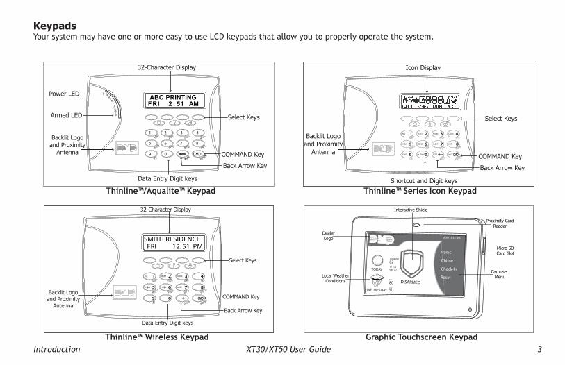
KeypadsYour system may have one or more easy to use LCD keypads that allow you to properly operate the system.
32-Character Display
Armed LED
Power LED
Data Entry Digit keys
COMMAND Key
Back Arrow Key
Select Keys
1 2 3 4
9 0 CMD
5 6 7 8
ABC PRINTINGFRI 2 : 51 AM
Backlit Logo and Proximity
Antenna
Thinline™/Aqualite™ Keypad
Icon Display
Shortcut and Digit keys
Backlit Logo and Proximity
AntennaCOMMAND Key
Back Arrow Key
Select Keys
Thinline™ Series Icon Keypad
MON 5:35 AM
DISARMED
Panic
Chime
Check-In
Reset
TODAY
WEDNESDAY
82
98 77
80LO74
HI
HI LO
CURRENT
Interactive Shield
Proximity CardReader
Micro SDCard Slot
Carousel Menu
DealerLogo
Local WeatherConditions
Graphic Touchscreen Keypad
32-Character Display
Data Entry Digit keys
COMMAND Key
Back Arrow Key
Select Keys
Backlit Logo and Proximity
Antenna
SMITH RESIDENCEFRI 12: 51 PM
Thinline™ Wireless Keypad

4 XT30/XT50 User Guide Introduction
The Select keysThinline™, Aqualite™, Icon and Wireless Keypads:There are four keys under the display called the Select keys. These keys are one of the features that make your system so easy to operate. They allow you to make selections by pressing the Select key under a choice shown in the display.
Note: For the purposes of this guide, when instructed to press the first Select key, press the far left Select key; the secondSelect key is the second from the left; third Select key issecondfromtheright;andthefourthSelectkeyisthefarright key.
Clear Touch™ and Graphic Touchscreen Keypads:There are four Select Areas in the display. These Select Areas are one of the features that make your system so easy to operate. They allow you to make selections by touching the area to choose the item in the display.
Note: For the purposes of this guide when using Clear Touch™ or GraphicTouchscreen Keypads,when instructed to press the firstSelectkey,touchSelectArea1;thesecondSelectkeytouchSelectArea2;thirdSelectkeytouchSelectArea3;andthefourthSelectkey touch Select Area 4.
Power/Armed LEDThinline™, and Aqualite™ Keypads:The Power LED indicates the panel Power status. It is recommended you contact the service department when the Power LED is off or blinks.
LED Operation AC Battery
ON (Steady) OK OK
OFF Trouble N/A
BLINKS OK Trouble
The Armed LED is ON steady anytime any burglary protection area is armed and is OFF when ALL areas are disarmed.
Clear Touch™ and Graphic Touchsreen Keypads:The LED indicates the Power and Armed status of the panel. Depending on the operation, the LED displays in Red or Blue as listed in the table.
Color and Activity LED OperationBlue Steady Panel Disarmed, AC Power OK, Battery OKBlue Blinking Panel Disarmed, AC Power OK, Battery FaultNo Light Panel Disarmed, AC Power Fault, Battery OKRed Steady Panel Armed, AC Power OK, Battery OKRed/Blue Alternate Panel Armed, AC Power OK, Battery FaultRed Blinking Panel Armed, AC Power Fault, Battery OK
32-Character Display
Select Area 1Select Area 3Select Area 2
Select Area 4
Touch Select Areas

Introduction XT30/XT50 User Guide 5
Power/Armed LogoThinline™ Wireless Keypads:The backlit logo on the keypad indicates the keypad Power status and Armed status of the panel. Depending on the operation, the logo displays Red or Green as listed in the table.
Color and Activity Armed Status Keypad Power StatusGreen Steady Panel Disarmed AC Power OK, Battery OKGreen Blinking Panel Disarmed AC Power OK, Battery FaultNo Light Panel Disarmed AC Power Fault, Battery OKRed Steady Panel Armed AC Power OK, Battery OKRed/Green Alternate Panel Armed AC Power OK, Battery FaultRed Blinking Panel Armed AC Power Fault, Battery OK
Panic FunctionsYour keypad may be set up to send a Panic, Emergency, or Fire report to the central station. This function is optional. If this option is programmed for your keypad, icons display below the top row Select keys/areas.
Thinline™, Aqualite™, Icon and Wireless Keypads:Press and hold the two Select keys adjacent to the desired icon for 2 seconds, until a beep from the keypad is heard.
Top Row Select Keys
Police Emergency Fire
Thinline™/Aqualite™/Thinline™ Icon Keypad Panic Keys With Shaded Buttons To Indicate Police Panic Keys
Clear Touch™ and Graphic Touchscreen Keypads:Touch the icon for 2 seconds until a beep is heard.
Clear Touch™ Keypad Panic Icons Graphic Touchscreen Panic Icons
7/0 Panic FunctionThinline™, and Aqualite™ Keypads:Security Command™, Thinline™, and Aqualite™ Keypads may also be programmed at installation to allow the user to initiate an optional Panic alarm by simultaneously pressing and holding the 7 and 0 (zero) keys. When the 7 and 0 keys are pressed for a short time, the keypad sends a Panic alarm report to the central station.
Note: Note: The 7/0 Panic Function is not available on Clear Touch™, Thinline™ Icon, Wireless, or Graphic Touchscreen keypads.
PANIC OPTIONSPRESS AND HOLD BUTTON TO SEND
FIREPOLICE EMERGENCY
Police Emergency Fire
Touch Select Areas

6 XT30/XT50 User Guide Introduction
On Thinline™, or Aqualite™ Keypads: This sets the LCD display, AC LED, and keyboard backlighting brightness level.
Clear Touch™ Keypads: The user selected brightness may be set to off which allows the backlighting to turn off (clear glass). Simply touch the glass anywhere and the backlight illuminates for data entry. When the speaker is sounding, the backlight illuminates at one-half (1/2) brightness.
Thinline™ Icon and Wireless Keypads: This sets the LCD display, keyboard, and logo backlighting brightness level.
Graphic Touchscreen Keypads: Set the backlight illumination and AC Power/Armed LED brightness level. In the touchscreen display below SET BRIGHTNESS, press the left < to lower and the right > to raise the backlight brightness. If the brightness level is lowered, it reverts to maximum intensity whenever the screen is pressed during normal operation. If the screen is not pressed, and the speaker has not sounded for 30 seconds, the user-selected standby brightness level restores.
Internal Speaker ToneSet the tone of the keypad internal speaker. At the SET TONE display, use the top left Select key to make the tone lower. Use the right Select key to make the tone higher. On Thinline™ Icon Series keypads, enter the desired speaker tone from the range of 1-8.
Volume levelSet the volume level of the keypad internal speaker for key presses. During alarm, trouble, and prewarn conditions, the volume is always at maximum level. At SET VOLUME LEVEL, use the left Select key to lower the keypad volume. Use the right Select key to raise the volume. On Thinline™ Icon Series keypads, enter the desired speaker volume level from the range of off (0) to maximum (8).
Common Keys on All KeypadsData Entry Digit keys These keys allow you to enter your user code when arming or disarming or enter other information into the system.COMMAND (CMD) keyThe COMMAND key allows you to advance through the keypad displays, User Menu, or complete a data entry function.
Back Arrow (<—) keyThe Back Arrow (<—) key is used to go back through the keypad displays while operating your system. You can press the Back Arrow key to back up through the list of functions in the User Menu or to erase the last character you entered.
Keypad User OptionsThe User Options menu allows you to make adjustments to your keypadtobestfityourenvironmentandneeds.Thinline™, Aqualite™, Icon and Wireless Keypads: Press and hold the Back Arrow and COMMAND keys for two seconds. The keypad display changes to SET BRIGHTNESS. Press the COMMAND key to display the next option or the Back Arrow key to exit.
Clear Touch™ Keypads: Touch and hold the center of the logo icon for two seconds. The display changes to SET BRIGHTNESS. Touch the COMMAND (CMD) key to display the next option or touch the Back Arrow (<—) to exit the User Options function.
Backlighting BrightnessAt the SET BRIGHTNESS display, use the left Select key to lower the keypad brightness. Use the right Select key to increase the brightness. On Thinline™ Icon Series keypads, enter the desired brightness from the range of off (0) to maximum (8).Note: If the brightness level is lowered, it temporarily reverts back
to maximum intensity whenever a key is pressed.

Introduction XT30/XT50 User Guide 7
open an entry delay door on a system that is armed (turned on) reminding you to disarm the burglary protection.Your systemwill silence the tone as soon as the first user codedigit key is pressed. If a valid user code is not entered within 5 seconds or an invalid user code is entered, the prewarn tone begins sounding again.
Exit tone: When fully arming your system to leave, a continuous pulsing tone sounds during the exit countdown just after arming to remind you to exit the premise. At ten seconds prior to the end of the countdown, the rate of pulsing increases.
Monitor tone: A pulsed tone that sounds one time for one second each time a door or window is opened while you are using the zone monitor function from the User Menu. See Zone Monitor.
Trouble tone: A steady tone indicating a trouble condition on your system. Press any key to silence the trouble tone.
What to do when the trouble tone soundsYou can silence the trouble tone by pressing any key. This only silences the keypad and does not correct the condition that originally caused the trouble.
Model NumberThinline™, Aqualite™, Wireless, Clear Touch, and Graphic Touchscreen Keypads:Thekeypadmodelnumber,firmwareversion,anddatedisplay,butcannot be changed.
Serial NumberThinline™ Wireless Keypads:The serial number assigned to the keypad displays. Press the Back Arrow key to exit the User Options function.Keypad AddressThe current address assigned to the keypad displays, but cannot be changed. Press the Back Arrow key to exit the User Options function.
Special Keypad TonesYour keypad also contains a small speaker that alerts you about events as they occur on your system. For burglary alarms, the tone willsilenceassoonasthefirstusercodedigitkeyispressed.Ifavalid user code is not entered within 5 seconds or an invalid user code is entered, the tone begins sounding again.
Below are brief descriptions of the different tones you hear from the keypad.
Fire alert: An intermittent sweeping siren from LCD keypads only thatcontinuouslyrepeatsuntilthefirealarmissilenced.Thisisinaddition to the bell output from the alarm panel.
Burglary alert: A siren tone from LCD keypads only that continues until the alarm is silenced. This is in addition to the bell output from the alarm panel.
Key press tone: A short beep as you press a key on the keypad.
Prewarn tone: A continuous pulsed tone that sounds when you
8 XT30/XT50 User Guide Introduction
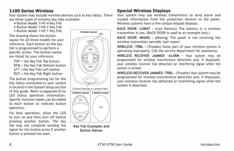
1100 Series WirelessYour system may include wireless devices such as key fob(s). There are three types of wireless key fobs available:
4-Button Model 1145-4 Key Fob 2-Button Model 1145-2 Key Fob 1-Button Model 1145-1 Key Fob
The drawing shows the button layout for all three models for your reference. Each button on the key fob is programmed to perform a specificaction.Thebuttonnamesare listed for your reference.
TOP = the Key Fob Top button BTM = the Key Fob Bottom button LFT = the Key Fob Left button RGT = the Key Fob Right button
The button programming list for the key fob(s) connected to your system is located in the System Setup section of this guide. Refer to Appendix B for LED Status operation information. Specificfunctionlabelscanbeaddedto each button to indicate button operation.
For best operation, allow the LED to turn on and then turn off before pressing another button. The key fob may not complete sending the signal for the button press if another button is pressed too soon.
Special Wireless DisplaysYour system may use wireless transmitters to send alarm and trouble information from the protection devices to the panel. Wireless systems have a few unique keypad displays.
BACK DOOR -LOBAT - (Low Battery) The battery in a wireless transmitter is low. (BACK DOOR is used as an example only.)BACK DOOR -MISNG - (Missing) The panel is not receiving the wireless transmitter periodic test report.WIRELESS -TRBL - (Trouble) Some part of your wireless system is operating improperly. Call the service department for assistance.WIRELESS RECEIVER JAMMED -ALARM - Your system may be programmed for wireless interference detection and, if displayed, your wireless receiver has detected an interfering signal while the system is armed.WIRELESS RECEIVER JAMMED -TRBL - (Trouble) Your system may be programmed for wireless interference detection and, if displayed, your wireless receiver has detected an interfering signal while the system is disarmed.
Connect Keyring or Lanyard Here
LED
2-Button Layout 1-Button Layout
4-Button Layout
TOP
TOP
BTM
LFT RGT
TOP
BTM
Key Fob Examples and Button Names

Introduction XT30/XT50 User Guide 9
TRY AGAIN or INVALID CODEThe code entered is not recognized by the system. Check the user code and try again.
TRBL (TROUBLE)There is a problem with a protection device or system component. This display is accompanied by a description of the problem.
SYSTEM TROUBLE or SERVICE REQUIREDThere is an electronic failure in your system. Contact the service department as soon as possible.
TEST IN PROGRESSThe system is currently being tested by an installation or service technician.
Special Keypad DisplaysAs you use your system, you may occasionally see a keypad display that asks you to enter a user code or describes a condition on the system. Below are some examples of the displays you may see.ALARMA24-hourzone,suchasafireorpaniczone,oranarmedburglaryzone is faulted. Your system may sound bells or sirens.ALARM NOT SENTThe alarm signal was aborted and was not sent to the central station because a user code was entered to disarm the system before the alarm signal was sent to the central station. Also, your system may be pre-programmed at installation to send an Abort signal to the Central Station. Refer to the Introduction section.
ALARM CANCELLEDAn Alarm signal just sent to the central station was cancelled because a user code was entered after the alarm was sent. Also, an Alarm Cancel signal is sent to the Central Station.
ALARM VERIFIEDAvalidburglaralarmhasoccurredandhasbeenmanuallyverifiedby the user. The alarm system also transmits a VERIFY message to the Central Station.
ENTER CODEThe system requires you to enter a personal user code. User codes can be used for turning your system on (arming), turning your system off (disarming), and other system options.As you enter your user code, the keypad display shows an asterisk (*) in place of each digit pressed. This prevents others from seeing your user code on the display as you enter it.

10 XT30/XT50 User Guide Introduction
Email/Cell Phone MessagesYour system may be programmed at installation to send a variety of messages to your personal email, and cell phone.
The message option uses your security system’s reporting capability to send reports using an email address or cell phone number in much the same way as someone sending an email would do. You can receive reports of alarms, troubles, or system armings and disarmings and know at a glance your system status. See Appendix D for more information.
MyAccess™ Text Messaging CommandsYour system may be programmed to allow simple text messages to be sent to the security system and perform basic user operations. By texting a message from your cell phone or PDA, the following actions can be performed: Arm/Disarm, check Armed Status, Cancel Alarm, and turn Outputs On/Off. Other operations that may be programmed from your cell phone or PDA include: Turning on and off lights, Locking and unlocking doors, and Setting the thermostat. See Appendix D for more information.
Understanding Security System TermsThroughout this guide, and in some displays on your keypad, you may see certain words or phrases that might be unfamiliar.Below are some terms you will see here and on the keypad display.
ArmingThis is the term used for turning on the burglary protection in one or more areas of the system. Your system may require you to enter a user code. When armed, the system can sound alarm bells or sirens and, if monitored, send alarm reports to a central station when a burglary zone is faulted.Fire, panic, and other 24-hour devices are always turned on and do not need to be armed.
DisarmingThis means turning off one or more areas of the system. When disarmed, the system does NOT sound alarms or send alarm reports to a central station when a burglary zone faults.
ZoneA zone refers to one or more protected openings or pro tection devices assigned the same zone number. Each door or window, motion detec tor, smoke detector, or other device has a zone number and a name.Often, similar devices in the same general area share the same zone. For example, the windows on the east side of the premises can all be grouped together in a zone named E. WINDOWS.
Entry or Exit ZoneAlmost all systems have one or more doors through which you can enter or exit the premises. These doors are programmed with a delay time to allow you to enter or exit while the system is armed without setting off the alarm.When you arm the system, activity on all burglary zones is ignored until the programmed exit delay time expires. Once that time has expired and the system is fully armed, opening the door causes the panel to start the entry delay time. During the entry delay time, enter a valid user code to disarm the system or an alarm occurs.
Instant ZoneExterior windows and non-entry doors, or interior protection devices, are typically not programmed with delay times. If these zones fault while the system is armed, an alarm occurs instantly.
24-Hour ZoneA 24-hour zone is not turned on or off by arming or disarm ing your system. Some examples of 24-hour zones are fire zones, paniczones, and temperature control zones.

Introduction XT30/XT50 User Guide 11
AreasAn area is made up of burglary zones that can be armed or disarmed together. The Perimeter area, for example, consists of all the doors and windows on the outside of the building. When you arm the Perimeter, these zones sound an alarm if tripped.
Central Station MonitoringYour system can also be programmed to automatically send alarm, trouble, and arming and disarming reports to a central station. Operators at the central station can then dispatch the appropriate authoritiesorcontactyouwiththespecificeventinformation.
StatusStatus is a feature that automatically displays the system armed or dis armed status on the keypads. Alarm or trouble con ditions on a zone or a system monitor such as AC or battery trouble can also display. There are two types of status information available: Status List and Armed Status.
Status ListThe keypad Status List displays any alarm or trouble condition on a zone and any trouble condition that occurs with the AC power or battery power. If your system contains any Panic zones, these do not display on the keypad for security reasons.
Ifanalarmoccursonanon-fire,24-hourzoneorasystemmonitor,it remains in the Sta tus List until it re stores. If one or more armed burglary zones trips, the last one to trip remains in the Status List. The burglary zone alarm remains in the Status List until it is cleared by disarming the system.
Zone StatusTo display the status of a particular zone, enter the zone number followed by the COMMAND key when the keypad displays the Status List.
Armed StatusWith Armed Status, the keypad displays the current armed condition of areas within your security system.
The keypad displays WhenHOME SYSTEM ON The perimeter areas is armed in a
Home/Away system.
PERIMETER ON The perimeter is armed in an All/Perimeter system.
ALL SYSTEM ON All areas are on.
SLEEP SYSTEM ON The perimeter and interior areas are on but the bedroom area is off.
Also, for keypads that include an Armed LED, the Armed LED is ON steady anytime a burglary protection area is armed and OFF when ALL areas are disarmed.
Exit ErrorThis is an automatic panel function that occurs if an exit door does not close all the way after the system is armed.
For example, if the front door is left ajar upon exit and the exit delay time expires, the system attempts to arm the front door zone but recognizes the open condition. The system sounds the alarm sirens and starts the entry delay. If the open condition is not corrected, an alarm and exit error is reported to the central station.
The Exit Error feature allows the central station to acknowledge the arming error without dispatching the police on a false alarm.

12 XT30/XT50 User Guide Arming and Disarming
Arming and DisarmingArming FunctionsArming:Duringarming,thesystemverifiesthatalldoors,windows,and other protection devices to be armed are in normal condition. If everything is normal, the system arms. If there is a problem on one or more burglary zones, the keypad displays the problem and allows you to correct the problem or bypass those zones.
If the problem can be corrected by closing a door or window, do not bypass the zone. Instead, correct the problem and try arming again. If the problem cannot be corrected, you can bypass the zone or wait until the zone can be repaired by a service technician. A bypassed zone is ignored by the system during the armed period.
In some cases the keypad might display FRONT DOOR - FAULT. The keypad may then display PRIORITY ZONE, which is a zone that cannot be bypassed. The problem on the zone must be corrected before the system can be armed.
After making your arming selection, the keypad displays any zones that are currently bypassed. These zones remain bypassed until the system is armed and then disarmed. Any 24-hour zones in a faulted condition also display.
Armed Message: After completing all bypasses or correcting zone faults, the areas selected are armed.
ForAll/PerimetersystemsthekeypadbrieflydisplaysALL SYSTEM ON if all areas in the system are arming or PERIMETER ON if only selected areas are arming.
For Home/Away or Home/Sleep/Away systems the keypad displays ALL SYSTEM ON if all areas in the system are arming, HOME SYSTEM ON or SLEEP SYSTEM ON if only selected areas are arming.
How Your System OperatesYour system has been programmed to operate in one of three modes: Area, All/Perimeter or Home/Sleep/Away.
• Area — Your burglary protection is divided into up to six areas. Each area can have a custom name, be turned on or off independently of other areas, and limit access to only those users with proper authority.
• All/Perimeter — Your burglary protection is divided into two areas: Interior and Perimeter.
Perimeter arming is for when you are staying inside but want the comfort of knowing the exterior doors and windows are armed. Perimeter arming allows you to move freely about inside without setting off any interior alarms.
All arms both the Perimeter and the Interior of the system. You want to arm both of these areas when leaving the building and no one is left inside.
• Home/Sleep/Away — Your burglary protection is divided into two or three areas: Perimeter, Interior, and Bedrooms.
Home (Perimeter) arming is for when you are staying inside but want the comfort of knowing the exterior doors and windows are armed.
Sleep (Perimeter and Interior) arms all areas except those near bedrooms and nighttime areas.
Away (Perimeter, Interior, and Bedrooms) arms all three areas for when you leave the building and no one is left inside.
Regardless of which mode is programmed, much of the operation is similar. Throughout this guide, any differences between the systems are noted for your convenience.

Arming and Disarming XT30/XT50 User Guide 13
Exit Delay: The keypad then displays the exit delay time as it counts down. If the entire system has been armed, your system beeps the exit delay tone at eight-second intervals until the last 10 seconds when the keypad beeps at three-second intervals. After exiting the building, if you re-enter during the countdown the exit countdown restarts, allowing additional time to then disarm or again exit the building during the countdown. This restart can occur only one time. When the exit delay time ex pires, all disarmed zones are armed. If your system uses a keyswitch to arm an area, the exit delay time does NOT count down on the keypad display.
When you arm both the Perimeter and Interior to leave the building but then you do not exit by the time the exit delay ends, the system automatically arms but the interior area(s) will remain disarmed because you have not exited.
Should you exit the building and the door does not close properly, your system may be programmed so that when the exit delay countdown ends, then the entry delay starts and the bell will sound to alert you to the situation. Enter your user code to stop the bell and disarm the system. Rearm the system, exit the building, and make sure the door is securely closed.
ONE MOMENT . . . Message: If your system is monitored, it may be programmed to wait for the arming report to be sent to the monitoring station before displaying the armed mes sage. (See ArmingReportbelow.)Thisverifiesthatthearmingmessagewasreceived by your monitoring station. While the system waits, the display reads ONE MOMENT.... If the report is received, the keypad buzzes for one second and displays the armed message. If the report is not received, the keypad displays LOCAL ALARM ONLY before displaying the armed message.
Arming Report: Your system may be pre-programmed at installation to send arming or zone bypass reports to a central station.
Key Fob ArmingPress the key fob button programmed for Arming or Toggle (Arm/Disarm) button. A Red LED two-second acknowledgement indicates All System On. A Green/Red two-second acknowledgement indicates System On with some areas armed.
Key Fob DisarmingPress the key fob button programmed for Disarming or Toggle (Arm/Disarm) button. A Green LED two-second acknowledgement indicates All System Off.
Area System ArmingArea Assignment: Your security system is programmed into separate areas. The number of areas and their names are listed in the back of this guide.
Arming or Disarming: You can arm and disarm all areas at one time or each area individually. You can only arm or disarm areas authorized for your user code.
All or Selective Arming: After entering your user code, the system allows you to arm either all of the areas to which you have access or one or more selected areas. If you choose to arm all areas, the system begins verifying that all zones in those areas are in a good condition. If you choose to arm selected areas, the system prompts you to choose the areas you want to arm.
Arming the System1. Press the COMMAND key until ARM DISARM displays.2. Select ARM to turn on all protection.3. Enter your user code if required. The display reads
ALL? NO YES.4. Select NO to arm only selected areas. Go to step 5. Select
YES to arm all areas authorized for your user code.

14 XT30/XT50 User Guide Arming and Disarming
5. If NO is selected in step 4, the display begins to list each area to which you have access followed by NO YES. Example: OFFICE NO YES.5a. Select YES for each area you want to arm.5b. Select NO for each area you do NOT want to arm.
Note: You can also simply press the area numbers you want to arm while ALL? NO YES displays. This changes the display to AREAS:. The numbers you select appear in the display. For example: AREAS: 2 4. Press COMMAND when done.
6. The system displays any faulted and bypassed zones in the following order: faulted burglary zones, bypassed burglary zones, faulted 24-hour zones, and bypassed 24-hour zones.
7. At this point you can force arm or bypass any faulted burglary zones. A zone that is force armed is restored into the system if it later returns to normal. A zone that is bypassed remains bypassed until the system is disarmed. See steps 7a through 7d.7a. If a problem exists on any zones, the zone name and problem are shown followed by: OKAY BYPASS STOP.7b. Select OKAY to force arm the zone(s) before arming.7c. Select BYPASS to bypass the zone(s) before arming.
Note: 24-hour zones cannot be bypassed.7d. Select STOP to stop the system from arming. Correct the zone problem(s) and return to step 1.
8. The display reads SYSTEM ON if at least one area in the system is armed, and ALL SYSTEM ON if all areas in the system are armed.
9. The keypad then displays the exit time in seconds and counts down the remaining time: EXIT: # # (# # = seconds remaining). When the entire system is armed, the keypad sounds the exit delay alert and when the delay expires, all zones are armed.
Area System DisarmingDisarming: While the system is armed, you can only enter the premises through an exit/entry delay door without causing an alarm. After opening the door, the keypad sounds a prewarn tone to remind you to disarm the system. You must disarm the system before the delay time expires or an alarm on the door zone occurs.During the prewarn tone, the keypad displays ENTER CODE: Enter your user code to disarm the system. Only those areas authorized for your user code disarm.Note: Yoursystemwillsilencethetoneassoonasthefirstusercode
digit key is pressed. If a valid user code is not entered within 5 seconds or an invalid user code is entered, the prewarn tone begins sounding again.
All or Selective Disarming: After entering your user code, the system allows you to disarm either all of the areas to which you have access or just selected areas. If you choose to disarm all areas, the system automatically disarms them. If you choose to disarm selected areas, the names of those areas display on the keypad.Z-Wave Lock Disarming: If your system is installed with a Z-Wave compatible lock, a valid user code entered at the lock will unlock the door and disarm the areas to which you have access.Alarm Display: After disarming, the keypad displays any zones that went into alarm or any communication problems that occurred during the armed period. All burglary zones are then disarmed and any bypassed zones are automatically reset.Disarmed Message: The keypad displays ALL SYSTEM OFF after the system disarms.Central Station Report: Your system may be pre-programmed at installation to send a report of the disarming to the central station.

Arming and Disarming XT30/XT50 User Guide 15
Disarming During an Alarm1. While the alarm bell or siren sounds, enter your user code
to silence the alarm. The keypad tone silences as soon as thefirstkeyispressed.For a burglary alarm, the keypad displays IS THIS A FALSE ALARM? NO YES or CANCEL VERIFY.This allows you to investigate the alarm prior to disarming the system. This display remains on the keypad until a selection is made, the Back Arrow is pressed, or the internal system bell cutoff timer expires.
2. If a valid alarm has not occurred, select YES or CANCEL to disarm the system and cancel the alarm.ThekeypadnextdisplaysALLSYSTEMOFFtoconfirmthesystem is disarmed.ORIf the alarm is valid, select NO or VERIFY to send a verify message to the Central Station. The system will remain armed.
All/Perimeter System ArmingArea Assignment: Your security system is divided into two separate areas. Motion detectors, inside doors, and other interior protection devices are assigned to the Interior area while windows and exterior doors are assigned to the Perimeter area.
Perimeter or All: When arming an All/Perimeter system, the keypad displays PERIM ALL. If you select ALL, you arm both the Perimeter and the Interior of the system. You want to arm both of these areas when leaving with nobody left inside. Selecting PERIM arms only the Perimeter of the system. Perimeter arming is for when you are staying inside but want the comfort of knowing the exterior doors and windows are armed. Perimeter arming allows you to move freely about inside without setting off any interior alarms.
Disarming an Area System1. Press the COMMAND key until ARM DISARM displays. During
entry delay this process starts at step 3 below.2. Select DISARM to disarm areas.3. The keypad displays ENTER CODE: . Enter your user code
and press COMMAND. The keypad displays ALL? NO YES.4. Select YES to disarm all areas authorized for your user code.
4a. Select NO to disarm only certain areas individually. The keypad then displays the name of each area authorized for your code followed by the NO YES display.4b. Select YES to disarm the area displayed.4c. Select NO to not disarm and to display the next area.
Note: You can also just press the area numbers you want to disarm while at the ALL? NO YES display. This changes the display to AREAS: . The area numbers you select appear in the display. For example: AREAS: 2 4.To remove an area number from the display, press its corresponding number on the keypad. Press COMMAND when done.5. After all areas have displayed, any alarms or communication
problems that occurred during the armed period are shown.6. If all areas are disarmed, the keypad displays
ALL SYSTEM OFF.

16 XT30/XT50 User Guide Arming and Disarming
System Ready/System Not Ready Keypad DisplaysWhen all zones in the system are in a normal condition, the keypad displays SYSTEM READY. If there are one or more zones that are not in a normal condition, the keypad displays SYSTEM NOT READY. Pressing any Select key during this display shows the zone name allowing you to investigate the problem.
Instant ArmingInstant: During the exit delay time, you can cancel the exit and entry delays and cause all zones to be instant zones. Select INSTNT while the exit delay displays. This immediately arms the exit zones. However, no entry delay is provided and an alarm immediately occurs should an entry door be opened.
All/Perimeter Shortcut Key ArmingArm Perimeter — Press 6 for 2 seconds.
Arm All— Press 1 for 2 seconds.
Arming an All/Perimeter System1. Enter your code. The keypad displays PERIM ALL.2. Select PERIM to arm the Perimeter area only.3. Select ALL to arm both the Perimeter and Interior areas.4. The system displays any faulted and bypassed zones in the
following order: faulted burglary zones, bypassed burglary zones, faulted 24-hour zones, and bypassed 24-hour zones.
5. At this point you can force arm or bypass any faulted burglary zones. A zone that is force armed is restored into the system if it later returns to normal. A bypassed zone remains bypassed until the system is disarmed. See steps 5a through 5d.5a. If a problem exists on any zones, the zone name and problem display followed by: OKAY BYPASS STOP.
5b. Select OKAY to force arm the zone(s) before arming.5c. Select BYPASS to bypass the zone(s) before arming.5d. Select STOP to stop the system from arming. Correct the zone problem(s) and return to step 1.
6. The keypad displays PERIMETER ON if only the perimeter is being armed and ALL SYSTEM ON if both the perimeter and interior are being armed.
7. The keypad next displays EXIT: ## INSTNT and begins to count down the number of seconds remaining for you to exit. If the entire system is armed, the keypad sounds the exit delay alert and when the delay expires, all zones are armed.
8. You can select INSTNT while EXIT: ## INSTNT displays to immediately arm all zones and make them instant. The keypad displays INSTANT. When you select INSTANT, any entry/exit zone that trips immediately activates an alarm and the exit delay countdown immediately stops.
9. When the system is armed, the keypad displays PERIMETER ON for perimeter arming and ALL SYSTEM ON for perimeter and interior arming.
All/Perimeter System DisarmingDisarming: While the system is armed, you can only enter the premises through an entry/exit delay door without causing an alarm. After opening the door, the keypad sounds a prewarn tone to remind you to disarm the system. You must disarm the system before the prewarn tone expires or an alarm on the door zone occurs.
During the prewarn tone, the keypad displays ENTER CODE:. Enter your user code to disarm the system.

Arming and Disarming XT30/XT50 User Guide 17
Note: Your systemwill silence the toneas soonas thefirstusercode digit key is pressed. If a valid user code is not entered within 5 seconds or an invalid user code is entered, the prewarn tone begins sounding again.
Alarm Display: After disarming, the keypad dis plays any zones that tripped or any transmission problems that occurred dur ing the armed period. All burglary zones are then dis armed and any by-passed zones automatically reset.
Disarmed Message: The keypad displays ALL SYSTEM OFF after the system disarms.
Central Sta tion Report: Your system may be pre-programmed at installation to send a report of the system disarming to the central sta tion.Z-Wave Lock Disarming: If your system is installed with a Z-Wave compatible lock, a valid user code entered at the lock will unlock the door and disarm the system.
Disarming an All/Perimeter System1. During the entry delay time, the keypad displays ENTER
CODE:. Enter your user code.
2. The keypad displays any zones that went into alarm and any communication problems that occurred during the armed period.
3. The keypad next displays ALL SYSTEM OFFtoconfirmthesystem is disarmed.
Disarming During an Alarm1. While the alarm bell or siren sounds, enter your user code
to silence the alarm. The keypad tone silences as soon as thefirstkeyispressed.For a burglary alarm, the keypad displays IS THIS A FALSE ALARM? NO YES or CANCEL VERIFY.This allows you to investigate the alarm prior to disarming the system. This display remains on the keypad until a selection is made, the Back Arrow is pressed, or the internal system bell cutoff timer expires.
2. If a valid alarm has not occurred, select YES or CANCEL to disarm the system and cancel the alarm.ThekeypadnextdisplaysALLSYSTEMOFFtoconfirmthesystem is disarmed.ORIf the alarm is valid, select NO or VERIFY to send a verify message to the Central Station. The system will remain armed.

18 XT30/XT50 User Guide Arming and Disarming
Home/Away System ArmingArea Assignment: Your security system is divided into two or three separate areas. Motion detectors, inside doors, and other interior devices are assigned to an Interior and possibly Bedroom area while windows and exterior doors, are assigned to a Perimeter area.
Arming the system: When arming a Home/Away system, the keypad displays HOME AWAY or HOME SLEEP AWAY. If you select AWAY, you arm all areas of the system. You want to arm all areas when leaving with nobody staying inside.
Selecting HOME arms only the system Perimeter. Perimeter arming is for when you are staying inside but want the comfort of knowing the exterior doors and windows are armed.
Selecting SLEEP arms the Perimeter and Interior devices but leaves devices near bedrooms and other nighttime areas off.
System Ready/System Not Ready Keypad DisplaysWhen all system zones are in a normal condition and can be armed without bypassing, the keypad displays SYSTEM READY. If there are one or more zones that are not in a normal condition, the keypad displays SYSTEM NOT READY. Pressing any Select key during this display shows the faulted zone name.
Home/Sleep/Away Shortcut Key ArmingArm Home — Press 3 for 2 seconds to arm the perimeter.
Arm Sleep — Press 7 for 2 seconds to arm the perimeter and interior areas and leave the bedroom area off.
Arm Away — Press 1 for 2 seconds.
Arming a Home/Away System1. Enter your user code. The keypad displays HOME AWAY or
HOME SLEEP AWAY (you may have three areas).2. Select HOME to arm the Perimeter only.3. Select SLEEP to arm the Perimeter and Interior.4. Select AWAY to arm the Perimeter, Interior, and Bedroom.5. The system displays any faulted and bypassed zones in the
following order: faulted burglary zones, bypassed burglary zones, faulted 24-hour zones, and bypassed 24-hour zones.
6. At this point you can force arm or bypass any faulted burglary zones. A zone that is force armed is restored into the system if it later returns to normal. A zone that is bypassed remains bypassed until the system is disarmed. See steps 6a through 6d.6a. If a problem exists on any zones, the zone name and problem display followed by: OKAY BYPASS STOP.6b. Select OKAY to force arm the zone(s) before arming.6c. Select BYPASS to bypass the zone(s) before arming.6d. Select STOP to stop the system from arming. Correct the zone problem(s) and return to step 1.
7. The keypad displays HOME SYSTEM ON if you selected HOME, or SLEEP SYSTEM ON if you selected SLEEP, or ALL SYSTEM ON if you selected AWAY.
8. The keypad next displays EXIT: ## INSTNT and begins to count down the number of seconds remaining for you to exit. The keypad sounds the exit delay alert and when the delay expires, all zones are armed.
9. You can select INSTNT while EXIT: ## INSTNT displays to immediately arm all zones and make them instant. The keypad displays INSTANT. When you select INSTANT, any entry/exit zone that trips immediately activates an alarm and the exit delay countdown immediately stops.

Arming and Disarming XT30/XT50 User Guide 19
Disarming a Home/Away System1. During entry delay, the keypad displays ENTER CODE:.
Enter your user code.2. The keypad then displays any alarms or communication
problems that occurred during the armed period.3. The keypad next displays ALL SYSTEM OFFtoconfirmthe
system is disarmed.
Disarming During an Alarm1. While the alarm bell or siren sounds, enter your user code
to silence the alarm. The keypad tone silences as soon as thefirstkeyispressed.For a burglary alarm, the keypad displays IS THIS A FALSE ALARM? NO YES or CANCEL VERIFY.This allows you to investigate the alarm prior to disarming the system. This display remains on the keypad until a selection is made, the Back Arrow is pressed, or the internal system bell cutoff timer expires.
2. 2. If a valid alarm has not occurred, select YES or CANCEL to disarm the system and cancel the alarm.
ThekeypadnextdisplaysALLSYSTEMOFFtoconfirmthesystem is disarmed.
OR
If the alarm is valid, select NO or VERIFY to send a verify message to the Central Station. The system will remain armed.
10. When the system is armed, the keypad displays HOME SYSTEM ON for Perimeter arming, SLEEP SYSTEM ON for Perimeter and Interior arming, and ALL SYSTEM ON for all areas armed.
Home/Away System DisarmingDisarming: While the system is armed, you can only enter the premises through an entry/exit delay door without causing an alarm. After opening the door, the keypad sounds a prewarn tone to remind you to disarm the system. You must disarm the system before the prewarn tone expires or an alarm on the door occurs.
During the prewarn tone, the keypad displays ENTER CODE:. Enter your code to disarm the system.
Note: Your systemwill silence the toneas soonas thefirstusercode digit key is pressed. If a valid user code is not entered within 5 seconds or an invalid user code is entered, the prewarn tone begins sounding again.
Alarm Display: After disarming, the keypad dis plays any zones that tripped or any communication problems that occurred dur ing the armed period. All burglary zones are then dis armed and any by-passed zones automatically reset.
Disarmed Message: The keypad displays ALL SYSTEM OFF after the system disarms.
Central Sta tion Report: Your system may be pre-programmed at installation to send a report of the system disarming to the central sta tion and/or to your email address or cell phone.
Z-Wave Lock Disarming: If your system is installed with a Z-Wave compatible lock, a valid user code entered at the lock will unlock the door and disarm the system.

20 XT30/XT50 User Guide Arming and Disarming
Keypad Shortcut KeysYour LCD keypad provides one-button shortcut keys. Holding down the selected keypad button for two seconds until the tone re-sounds allows you to arm, monitor, or reset your system. These options can still be accessed through the User Menu if desired.
Keypad Key Arming System OperationPress Key 1 Arm Away for Home/Sleep/Away systems Arm All for All/Perimeter systemsPress Key 2 Sensor (Fire) Reset on all systemsPress Key 3 Arm Home for Home/Sleep/Away systemsPress Key 4 Check-in Report on all systemsPress Key 5 Monitor (Chime) on all systemsPress Key 6 Arm Perimeter for All/Perimeter systemsPress Key 7 Arm Sleep for Home/Sleep/Away systemsPress Key 8 Easy Exit for Home/Sleep/Away systems
Arming FunctionSystem Operation: Home/Sleep/Away, or All/Perimeter.You can use the Arming shortcut keys, 1, 3, 6, and 7 when the system is disarmed. You may be prompted to enter your user code. If any zones are faulted, select force arm or bypass. Refer to the Arming Section for detailed arming operation.
Home/Sleep/Away ArmingArm Home — Press 3 for 2 seconds to arm the perimeter.Arm Sleep — Press 7 for 2 seconds to arm the perimeter and
interior areas and leave the bedroom area off. This shortcut key is available when the system is disarmed and when the system is armed for Home mode.
Arm Away — Press 1 for 2 seconds.All/Perimeter Arming
Arm Perimeter — Press 6 for 2 seconds.Arm All— Press 1 for 2 seconds.
Sensor (Fire) Reset FunctionSystem Operation: Area, Home/Sleep/Away, or All/Perimeter.You can use the Sensor (Fire) Reset, shortcut key 2, when the system is armed or disarmed. When pressed, detectors that have latched due to an alarm condition are now restored and returned to normal function. The keypad displays SENSORS ON and SENSORS OFF to acknowledge the shortcut key press.
Note: You are prompted to enter your User Code on Area or All/Perimeter systems.
Monitor (Chime) FunctionSystem Operation: Area, Home/Sleep/Away, or All/Perimeter.You can use the Monitor (Chime), shortcut key 5, when the system is disarmed. When pressed, the Zone Monitor operation is initiated.
1 2 3 4
9 0 CMD
5 6 7 8A CB D FE G
IH JLK
VXWS UTP RQM ON
Y Z
AwayAll
Sensor Reset(Fire Reset) Home
Monitor(Chime)
Perimeter Sleep
Check-in Report(Latch Key)
Easy Exit
Keypad Shortcut Keys

Arming and Disarming XT30/XT50 User Guide 21
As needed, refer to the Zone Monitor section. The keypad displays MONITOR ON and chimes or displays MONITOR OFF and no tone is sounded.
Note: The Monitor (Chime) shortcut key applies to all Exit zones in an Area system and to all zones assigned to the perimeter in a Home/Sleep/Away or All/Perimeter system.
Check-in Report (Latch Key) FunctionSystem Operation: Area, Home/Sleep/Away, or All/Perimeter.Your system may be pre-programmed at installation to send messages to your personal email, PDA, or cell phone. You can use the Check-in Report (Latch Key), shortcut key 4, to have a Check-in Report message sent. Refer to Appendix D for Email/Cell phone message information.
Note: Check-in report function is not supported by Icon keypads.
Easy Exit™ FunctionSystem Operation: Home/Sleep/Away.You can use the Easy Exit, shortcut key 8, when the system is armed, to restart the exit delay allowing you to exit the premises without disarming the system. For example, to let a pet out or retrieve the newspaper. After the exit delay time expires, the system automatically rearms.
You can also press the Easy Exit, shortcut key 8 again, to cancel the exit delay countdown. For example, the telephone rings before you retrieve the newspaper so you press shortcut key 8 to rearm the system.

22 XT30/XT50 User Guide User Menu
User MenuBYPASS ZONES Allows you to Bypass a zone or reset an
already bypassed zone.ZONE MONITOR Allows you to add or remove a zone from
the monitor mode.SYSTEM TEST Tests the system siren, communication
to the central station, and backup battery.
USER CODES Allows you to add, delete, or change user codes and authority levels.
SCHEDULES Allows you to add, remove, or change system schedules.
DATE AND TIME Allows you change the Day, Date, or Time that is currently in the system.
DISPLAY EVENTS Allows you to view the last 100 events on the XT30 and 200 events on the XT50 that occurred on your system.
SERVICE REQUEST Allows you to send a message to the Central Station requesting service on the alarm system.
The following pages detail each User Menu item and provide instructions on when and how to use them properly.
Many of your system features have been put into a User Menu that you can access from a 32-character keypad. The menu requires you to enter your user code. Only those functions to which you have access display.
Accessing the User Menu1. Press the COMMAND key until MENU? NO YES displays.2. Select YES. The keypad displays ENTER CODE: — . Enter
your user code. You can now scroll down through the list of system features available to you.
User Menu OptionsThe following list shows the User Menu options in order:
Menu Option DescriptionUSER CHECKIN Allows check-in with the system to
indicate arrival on premises.ZONE ACTIVITY CHECK Allows you to monitor a zone for non-
activity.SENSOR RESET Resets smoke or glassbreak detectors
that have latched during an alarm condition.
OUTPUTS ON/OFF Allows you to turn on or off any of the outputs described in the System Setup section of this guide.
FAVORITES Allows you to activate any of the Favorites described in the System Setup section of this guide.
Z-WAVE SETUP Allows you to Add, List, Remove, Transfer, and Optimize Z-Wave devices in your system. You can create Z-Wave Favorites, Add, Edit, and Remove Z-Wave devices in Favorites.

User Menu XT30/XT50 User Guide 23
User Check-inUser Code Level: Master, Standard, Limited, or Scheduled.
Function: This feature allows you to monitor the arrival of children from school or employees to work by having a special Check-in Report sent to your email address or cell phone if programmed.
Note: Check-in report function does not work with Icon keypads.Appendix D describes the Email/Cell Phone option.
Sending a Check-in Report1. After disarming the system, access the User Menu.
2. At the USER CHECKIN? display, press any Select key. The keypad displays USER CHECKIN: 22 (22 = user number).
3. The panel sends the Check-in Report containing your account number and user number to the email address or cell phone number.
Check-in (Latch Key) Report Shortcut KeyAll Systems (except Icon keypads) — Press 4 for 2 seconds, then enter your user code to send a Check-in Report.
Zone Activity CheckUser Code Level: Master, Standard, Limited, or Scheduled.
Function: Your security system may be pre-programmed at installation for the Zone Activity Check feature allowing you to monitor a person for non-activity.
When no activity is detected for the programmed time period, your keypad sounds a steady tone for a set period of time and displays PRESS ANY KEY. Pressing any key on the keypad, before the steady tone stops, prevents your system from sending a “User Activity Not Detected” report to the central station. Pressing the key also restarts the zone activity timer.
This could be used for a person living alone to detect when they have not moved about to trip a disarmed zone within a programmed period of time. This feature is optional.
Note: The Zone Activity Check is disabled when a schedule is entered to allow for sleeping hours and is automatically enabled when an area is disarmed.
Selecting Zone Activity Check1. At the ACTIVITY CHECK? display, press any Select key. The
keypad displays ENABLE? YES NO. The default is YES.2. When NO is selected, the keypad displays CHECK DISABLED
for four seconds and then sends the Activity Check Disabled message to the central station.
3. When YES is selected, the keypad displays CHECK ENABLED for four seconds and then sends the Activity Check Enabled message to the central station.

24 XT30/XT50 User Guide User Menu
Sensor ResetUser Code Level: Master, Standard, Limited, or Scheduled.
Function: Resets smoke or glassbreak detectors. Also clears Fire and Supervisory zone alarms and trouble keypad displays. Sensor Reset also clears low battery displays if your system is using wireless sensors.
Once smoke or glassbreak detectors trip, they must be reset before they can detect any additional alarm conditions. When Sensor Reset is selected, power to the detectors is temporarily removed by the system allowing them to reset.
Make sure all smoke is cleared from around the area of the smoke detectors before performing a Sensor Reset to prevent the alarm from occurring again.
Resetting the Sensors1. Access the User Menu.
2. When SENSOR RESET? displays, press any Select key. The keypad displays SENSORS OFFforfivesecondsfollowedbySENSORS ON.
3. The keypad returns to the status display.
Sensor (Fire) Reset Shortcut KeyAll Systems — Press 2 for 2 seconds, then enter your user code if required, to reset the system.
Outputs On/OffUser Code Level: Master, Standard, or Limited.
Function: Allows you to turn the system outputs on and off.
This function is used to individually turn your system relay outputs on and off. Your system may use these outputs to control interior and exterior lighting, or heating, air conditioning, or other appliances.
The system output names and numbers are located in the System Setup section at the back of this guide.
Turning the Outputs On/Off1. Access the User Menu.
2. Press the COMMAND key until OUTPUTS ON/OFF? displays.
3. Press any Select key.
4. The keypad displays OUTPUT: - ON OFF.
5. Enter the output number you want to turn on or off. The output number appears in the display.
6. With the output number displayed, Select ON or OFF. The output is then turned on or off, depending on your selection, and remains in that state until you change it.
7. The system automatically removes the output number and a new output number can be entered. Refer back to step 5.
To exit the Output menu option, press the Back Arrow key until you return to the keypad Status List.

User Menu XT30/XT50 User Guide 25
Z-Wave SetupUser Code Level: Master.Your system may include a DMP Z-Wave controller module attached at installation. The Z-Wave controller module allows short range radio control of Z-Wave devices that you or your installation company may provide such as lighting control modules, thermostat controls, doors and garage doors. Z-Wave Setup allows you to program the system to control the Z-Wave devices. You may control your Z-Wave devices from your smart phone device using the DMP Virtual Keypad App or from your keypad by activating a Favorite from the Favorites User Menu. The available setup options are: Add, List, Remove, Favorites, Transfer and Optimize.
• Select ADD to add a Z-Wave device to your system.
• Select LIST to display a list of Z-Wave devices already added and stored in your system.
• Select REMOVE to completely remove a Z-Wave device from your system.
• Select FAV to Add, Edit or Remove a Favorite.
• Select XFER to transfer Z-Wave device information from another manufacturer’s portable Z-Wave controller to your system.
• Select OPT to update communication with all Z-Wave devices programmed on your system. OPT can be used to re-establish communication after the Z-Wave device has been moved to a different location.
FavoriteUser Code Level: Master, Standard, or Limited.
Allows you to activate a Z-Wave Favorite. Z-Wave devices can be grouped together to create Favorites. Favorites can only be activated, or turned on. A separate Favorite must be created to change the conditions set by the first Favorite. For a completedescription on how to add a Favorite to activate, see Adding a FAVORITE in Z-Wave Setup.
1. When FAVORITES? displays, press any Select key. The keypad displays FAVORITE: -.
2. Enter a Favorite number from 1-20. Pressing COMMAND activates the Favorite.

26 XT30/XT50 User Guide User Menu
Add Z-Wave Devices (ADD)This option allows you to ADD a Z-Wave device to your system. Once added, a Z-Wave device may be assigned to a Favorite.
1. Access the User Menu.2. Press COMMAND until ZWAVE SETUP? displays.3. Press any Select key. The keypad displays ADD LIST REMOVE.4. SelectADD.PROCESSINGmaybrieflydisplay.WhenPRESS
BUTTON ON DEVICE TO ADD displays press the program button on the Z-Wave device. See the Z-Wave device’s documentation for more information.
5. When the device information is received by the system, the keypad beeps once and displays DEVICE FOUND.
6. Once added, the keypad displays the type of device and the default device name. Press COMMAND.
7. Press any top row Select key and enter up to a 16 character custom name for the device. See Entering Names in Appendix D.
8. Press the COMMAND key to store the new name.Note: A maximum of 232 Z-Wave devices can be added to the
system. When the maximum number of devices have been added, the keypad displays ZWAVE TABLE FULL and no additional Z-Wave devices may be added without removing some existing devices.
List Z-Wave Devices (LIST)This option allows you to edit the name of a Z-Wave device or confirmradiocommunicationwiththeZ-Wavedevice.WhenLISTisselected,thefirstZ-Wave device stored in the system is displayed. Remaining devices can be viewed by pressing the COMMAND key. Lighting control modules, aredisplayedfirst,followedbydoors and then thermostat controls.
The available LIST options are: Rename and Status.• Select RENAME to enter up to 16 characters for a new
device name.• Select STATUS to confirm radio communication with the
Z-Wave device.
RENAME Z-Wave Devices1. Access the User Menu.2. Press COMMAND until ZWAVE SETUP? displays.3. Press any Select key. The keypad displays ADD LIST REMOVE.4. Select LIST to display DEVICE LIST and the first Z-Wave
device stored. Press the COMMAND key to advance through the list of Z-Wave devices.
5. Press any Select key to display DEVICE RENAME STATUS.6. Select RENAME and enter up to 16 characters for a new
device name. See Entering Names in Appendix D.7. Press COMMAND to save the new Z-Wave device name and
return to the DEVICE LIST.
STATUS of Z-Wave Devices1. Access the User Menu.2. Press COMMAND until ZWAVE SETUP? displays.3. Press any Select key. The keypad displays ADD LIST REMOVE.4. Select LIST to display DEVICE LIST and the first Z-Wave
device stored. Press the COMMAND key to advance through the list of Z-Wave devices.
5. Press any Select key to display DEVICE RENAME STATUS.6. Select STATUS to confirm radio communication with the
Z-Wave device.7. The device name and OKAY displays when the device stored
in the system communicates.

User Menu XT30/XT50 User Guide 27
8. Press the COMMAND key to return to the device list and display the next device in the list.
9. If the device stored in the system does not communicate, the device name and FAILED displays. Press the COMMAND key and REMOVE FAILED DEVICE displays.
10. Select YES to remove the failed device from the system memory. Select NO to leave the device in the system memory and to return to the device list.
11. When the device has been removed, the device name and REMOVED is displayed and the system no longer tries to communicate with the Z-Wave device.
Remove Z-Wave Devices (REMOVE)Each Z-Wave device added to your system remains in your system unless it is removed. This option allows you to remove Z-Wave devices from your system.
1. Access the User Menu.2. Press COMMAND until ZWAVE SETUP? displays.3. Press any Select key. The keypad displays ADD LIST REMOVE.4. Select REMOVE. PROCESSING may briefly display. When
PRESS BUTTON ON DEVICE TO REMOVE displays press the program button on the Z-Wave device, the device name and REMOVED is displayed to indicate the Z-Wave device has been removed.
Favorites (FAV)Z-Wave devices can be grouped together to create a Favorite. This option allows you to program up to 20 Favorites in your system and then ADD, EDIT OR REMOVE up to 25 Z-Wave devices in a Favorite. When activated from the FAVORITE user menu, a command is sent to its Z-Wave Devices. A Favorite can only be activated, or turned on. A separate Favorite must be created to change the conditions set by the first Favorite. For example, a Favorite called “Movie Night” could lock the exterior doors, close the garage door, adjust the temperature, and dim the lights in the family room to the desired level. Another Favorite called “Wakeup” could then turn on the lights, adjust the temperature, unlock the exterior doors, and raise the garage doors.Adding a FAVORITE
1. Access the User Menu.2. Press COMMAND until ZWAVE SETUP? displays.3. Press any Select key. The keypad displays ADD LIST REMOVE.4. Press COMMAND again to display FAV XFER OPT. Select FAV
and FAVORITE NUMBER: - is displayed.5. Enter a Favorite number between 1 and 20 and press
COMMAND. If the Favorite number entered is unassigned, *UNUSED* displays. If the Favorite is already assigned, you may change the name or press the back arrow and enter a new number.
6. Press any Select key and a cursor displays. Enter a Favorite name up to 16 characters. To remove a Favorite, press Command without entering a name.
7. Press COMMAND to save the Favorite and the Favorite name and ADD EDIT REMOVE displays.
ADD Devices to FAVORITES1. Access the User Menu.2. Press COMMAND until ZWAVE SETUP? displays.

28 XT30/XT50 User Guide User Menu
3. Press any Select key. The keypad displays ADD LIST REMOVE.4. Press COMMAND again to display FAV XFER OPT. Select FAV
and FAVORITE NUMBER: - is displayed.5. Enter a Favorite number between 1 and 20 and press
COMMAND.6. The Favorite number and name displays. Press COMMAND
and the Favorite Name and ADD EDIT REMOVE displays.7. Select ADD and the first Z-Wave device stored in the
system that has not already been added to this Favorite is displayed. Remaining devices can be viewed by pressing the COMMAND key.
8. Press any Select key to assign the displayed device to the Favorite. The device name and the current device settings display. When added to a Favorite, a Z-Wave device can be programmed to respond to various ON/OFF/LOCK/UNLOCK/OPEN/CLOSE/HEAT/COOL commands based on your desired settings. To change a device setting, See Device Settings in Favorites.
Device Settings in FAVORITESLights1. Press any Select key at SETTING: and ON OFF DIM
displays. Press the Select key under the desired setting.
2. For ON or OFF setting, when selected, the Favorite name and the next Z-Wave device stored in the system displays.
3. For DIM setting, DIM LEVEL: with the current setting displays. To change the setting, press any Select key and enter the new level (1 - 10) and Press COMMAND.
4. The Favorite name and the next Z-Wave device stored in the system displays.
Doors
1. Press any Select key at SETTING: LOCK UNLOCK for Doors and OPEN CLOSE displays for Garage Doors. To change the setting, press the Select key under the new setting.
2. The Favorite name and the next Z-Wave device stored in the system displays.
Thermostats
1. Press any Select key at SYSTEM: and OFF CL HT displays. To change the setting of OFF, COOL or HEAT, press the Select key under the new setting.
2. Select OFF to display FAN SETTING:.3. Press any Select key and ON AUTO displays. Press the
Select key under the desired new setting to change.4. Select CL to display COOL.5. To change the setting, press any Select key, enter the
new temperature and press COMMAND.6. Press any Select key and the keypad displays
FAN SETTING:.7. Press any Select key and ON AUTO displays. Press the
Select key under the desired new setting to change.8. Select HT to display HEAT.9. To change the setting, press any Select key and enter
the new temperature and Press COMMAND.10. Press any Select key and the keypad displays
FAN SETTING:.11. Press any Select key and ON AUTO displays. Press the
Select key under the desired new setting to change.12. The Favorite name and the next Z-Wave device stored
in the system displays.

User Menu XT30/XT50 User Guide 29
Note: A maximum of 25 devices can be assigned to each Favorite. When attempting to add a device and the maximum number of devices has been assigned, FAVORITE FULL is displayed. No additional Z-Wave devices may be added to this Favorite, however a new Favorite may be created and devices added to the new Favorite.
EDIT Devices in FAVORITES
1. Access the User Menu.2. Press COMMAND until ZWAVE SETUP? displays.3. Press any Select key. The keypad displays ADD LIST REMOVE.4. Press COMMAND again to display FAV XFER OPT. Select FAV
and FAVORITE NUMBER: - is displayed.5. Enter a Favorite number between 1 and 20 and press
COMMAND.6. The Favorite number and name displays. Press COMMAND
and the Favorite Name and ADD EDIT REMOVE displays.7. SelectEDITandthefirstZ-Wave device stored in the Favorite
displays. Remaining devices can be viewed by pressing the COMMAND key.
Note: Z-Wave devices are displayed by device type; Lights first,followed Doors, and Thermostats last. By pressing the COMMAND key you can scroll through the devices assigned to the selected Favorite.
8. Press any Select key to display the device name and the setting for the device.
9. To change the setting, See Device Settings in Favorites.10. Once the device settings have been entered, the Favorite
name and the next Z-Wave device stored in the selected Favorite displays.
REMOVE Devices from FAVORITES1. Access the User Menu.2. Press COMMAND until ZWAVE SETUP? displays.3. Press any Select key. The keypad displays ADD LIST REMOVE.4. Press COMMAND again to display FAV XFER OPT. Select FAV
and FAVORITE NUMBER: - is displayed.5. Enter a Favorite number between 1 and 20, press COMMAND. 6. The Favorite number and name displays. Press COMMAND
and the Favorite Name and ADD EDIT REMOVE displays.7. Select REMOVE and the firstZ-Wave device stored in the
Favorite displays. Remaining devices can be viewed by pressing the COMMAND key.
8. Press any Select key to remove the device from the Favorite. REMOVE DEVICE FROM FAV? NO YES displays. When YES is selected, the device is removed from the Favorite.

30 XT30/XT50 User Guide User Menu
Transfer Controller (XFER)This option allows the transfer of all existing Z-Wave devices that are currently programmed in another manufacturer’s Z-Wave portable controller to your system. This operation will overwrite all Z-Wave devices that are
programmed in your system. This option typically occurs at the time your DMP Z-Wave controller is installed.
Initiate the transfer at the other manufacturer’s Z-Wave portable controller after starting the transfer on the DMP keypad. Z-Wave devices are NOT overwritten until the transfer has been initiated at the other manufacturer’s Z-Wave portable controller. The transfer should not be stopped once the process has been initiated from the other manufacturer’s Z-Wave portable controller.
Transfer Operation:1. Access the User Menu.2. Press COMMAND until ZWAVE SETUP? displays.3. Press any Select key. The keypad displays
ADD LIST REMOVE.4. Press COMMAND again to display FAV XFER OPT. Select
XFER. The keypad displays XFER WILL DELETE EXISTING DEVICES then displays XFER CNTRL SURE? YES NO.
5. Select YES to to allow receipt of Z-Wave devices to your system. The keypad displays TRANSFERRING Z-WAVE DEVICES. Pressing the Back Arrow key cancels the transfer.Select NO to exit the XFER menu and return to ZWAVE SETUP?. All programming will still be intact on the DMP Z-Wave controller and will cancel the transfer.
6. Initiate the transfer at the other manufacturer’s Z-Wave portable controller. All Z-Wave devices are added to the system with a default name (device type and number). A 16-character name may be assigned to the Z-Wave devices after the transfer is complete. When the transfer is complete the screen will display ZWAVE SETUP?.
Note: If TRANSMISSION FAILED displays on the screen, your system memory is cleared of all prior Z-Wave devices programming and will need to add each Z-Wave device individually.
Optimize (OPT)Select Optimize (OPT) to update communication with all Z-Wave devices. Optimize can be used to re-establish communication after a Z-Wave device has been moved to a different location. When OPTIMIZE is selected, the panel makes three attempts to communicate with each Z-Wave device. Z-Wave devices that fail to communicate during the optimize process are not removed from panel programming.
1. Access the User Menu.2. Press COMMAND until ZWAVE SETUP? displays.3. Press any Select key. The keypad displays ADD LIST
REMOVE.4. Press COMMAND again to display FAV XFER OPT.5. Select OPT, the keypad displays OPTIMIZE while the system
is searching for Z-Wave devices.6. The keypad will display OPTIMIZE SUCCESS when Z-Wave
devices have been retrieved.7. Press COMMAND to return to ZWAVE SETUP?.
Note: The keypad will display OPTIMIZE FAILED when communication with a Z-Wave device is not established. Press COMMAND to return to ZWAVE SETUP? and attempt optimize again. If communication with a Z-Wave device is not re-established during the optimize process, make sure the device is powered on. If the device that failed has power, add a repeater between the panel and the device.

User Menu XT30/XT50 User Guide 31
Bypass ZonesUser Code Level: Master or Standard.Function: Allows you to bypass a zone prior to arming the system.Bypassing is usually done when a zone cannot be restored to normal and you want to arm the system. Once bypassed, the system does not respond to any activity on the zone.A zone can be bypassed only while it is disarmed. Since Fire, Panic, Emergency, and Supervisory zones are always armed, they can never be bypassed.The Bypass Zones function can also be used to restore a bypassed zone back into the system. This can only be done while the zone is disarmed. Disarming always resets a bypassed zone.Your system may be pre-programmed at installation to send a bypass report to your central station when Bypass Zones is selected.
Using the Bypass Zones Function1. Access the User Menu.2. Press the COMMAND key until BYPASS ZONES? displays.3. Press any Select key. The keypad displays ZONE - RST BYPS.4. To reset a zone, enter the zone number and Select RST.5. To Bypass a zone, enter the zone number and Select BYPS.
Zone MonitorUser Code Level: Master, Standard, or Limited.
Function: Allows the system to monitor selected disarmed zones (doors, windows, or motion detectors). When a monitored zone trips, the keypad sounds a tone and displays the zone name. This is an ideal feature for monitoring door zones to tell when someone comes in or goes out and for system testing.
You can place any combination of disarmed zones in Zone Monitor but only the most recently tripped zone displays. The displayed zone name clears automatically after a short time or when the zone is armed. Zone Monitor does not function while the system is armed but a zone placed into the Zone Monitor is still monitored when the system is disarmed.
Using Zone Monitor as part of your weekly system test: After using the System Test function, place all zones in Zone Monitor. Starting at the front door, walk around and open and then close each door and window. You should hear the keypad beep each time. The keypad also displays the name of each zone as its device is opened.
Once all protected doors and windows are tested, walk in front of each motion detector and trip any other protection devices on the system.Thekeypadshouldbeeptoconfirmtheiroperation.Ifatany time during your weekly testing a device does not cause the keypad to beep, call the service department for assistance.
Monitor (Chime) Shortcut KeyAll Systems — Press 5 for 2 seconds when the system is disarmed. This initiates the Zone Monitor operation for all Exit zones in an Area system or all zones assigned to the perimeter in a Home/Sleep/Away or All/Perimeter system. The keypad displays MONITOR ON and chimes or displays MONITOR OFF and no tone is sounded.

32 XT30/XT50 User Guide User Menu
Using the Zone Monitor Function1. Access the User Menu.2. Press the COMMAND key until ZONE MONITOR? displays.3. Press any Select key.
The keypad displays PERIM ALL NBR.4. Select PERIM to place all disarmed perimeter zones into
Zone Monitor.4a. The keypad dis`plays PERIM? ADD RMV.4b. Select ADD to add all perimeter zones to Zone Monitor.4c. Select RMV to remove all perimeter zones.
5. Select ALL to place all disarmed zones into Zone Monitor.5a. The keypad displays ALL? ADD RMV.5b. Select ADD to add all disarmed zones to Zone Monitor.5c. Select RMV to remove all disarmed zones.
6. Select NBR toenteraspecificzonenumberforzonemonitor.7. If NBR is selected, the keypad displays ZONE : - ADD RMV.
7a. Enter any zone number and select ADD to add this zone.7b. Enter any zone number and select RMV to remove the zone.
8. The zone number automatically disappears and a new zone number can then be entered. See step 7.
System TestUser Code Level: Master, Standard, or Limited.
Function: System Test is used to test the battery, alarm bell or siren, and central station communi cation. The System Test function begins automatically as soon as you select it.
Using the System Test Function1. Access the User Menu.
2. Press the COMMAND key until SYSTEM TEST? displays.
3. Press any Select key. The system test begins automatically and the keypad displays:
1) BELL SOUNDING during a two second bell test, then:
2) KEYPAD SOUNDING during a two second keypad test, then:
3) BATTERY - OKAY or BATTERY - TRBL to indicate the battery condition, then:
4) TRANSMIT TEST * and ATTEMPT NO : 1 during the transmit test, then:
5) TRANSMIT OKAY or TRANSMIT FAILED to show the transmit test results, then:
6) TEST END to indicate the System Test is complete.
7) Press the Back Arrow key to end the system test.
* The transmit test does not occur on local systems.
Testing your system burglary protection: The System Test function should be part of your weekly testing and should be followed by placing the interior and perimeter burglary devices in Zone Monitor mode. This allows you to open and then close each protected door andwindowwhilelisteningforthekeypadtobeepconfirmingitsoperation. See Zone Monitor.

User Menu XT30/XT50 User Guide 33
User CodesUser Code Level: Master only.Function: Allows you to add or delete a user from the system or change their user code or authority level.User code characteristics: There are three characteristics associatedwitheachusercodethatdefineitscapabilitieswithinthe system.
Characteristic ExampleUser Number 22User Code 3848Authority Level MasterUser Number - The XT30 panel supports 30 users while the XT50 panel supports 99 users. Each user is numbered from 1 to 30 or 1 to 99. This number identifies them to the system and can betransmitted to the central station (if your system is monitored) when they arm or disarm the system.User Code - Users also have a 4-digit user code they enter into the keypad when arming or disarming. This user code is kept secret from other users and is not transmitted to the central station when they arm or disarm.Note: A User Code cannot begin with zero and cannot be left blank.Users enter only their own user code when operating the system.User Names - Each code may also be programmed with the user name. You may enter up to 16 characters for the name. As needed, refer to Appendix C for Entering User Names information.Authority Level - The user is also assigned a level of authority (Master, Standard, Limited, or Scheduled) by the person administrating the system to determine the functions the user can access. The XT30 allows Master and Standard users while the XT50 allows all levels of authority.The Scheduled authority level only functions during a valid schedule, except for arming which can be done at any time.
Disarming is allowed outside of a schedule, but an UNAUTHORIZED ENTRY message is sent to the central station. All other authority levels function regardless of schedules.The table below lists system functions users are allowed to access based on the authority level assigned to their codes at the time they are added to the system.
User Menu Option Scheduled(XT50 Only)
Limited(XT50 Only)
Standard(XT30/XT50)
Master(XT30/XT50)
Door Access Y Y Y YArm and Disarm Y Y Y YAlarm Silence Y Y Y YUser Checkin Y Y Y Y
Zone Activity Check Y Y Y YSensor Reset Y Y Y Y
Outputs On/Off Y Y YFavorites Y Y Y
ZWave Setup YBypass Zones Y YZone Monitor Y Y Y YSystem Test Y Y YUser Codes YSchedules Y
Extend Y YSet Time Y
Display Events Y Y Y YService Request? Y
Adding User codesUser Code Level: Master only.
1. Access the User Menu.2. Press the COMMAND key until USER CODES? displays.

34 XT30/XT50 User Guide System Setup
3. Press any Select key.The keypad displays ADD DEL CHG BAT.
4. Select ADD to add a new user code.5. At the USER NUMBER: — prompt, enter a user number and
press COMMAND.6. The displays changes to CODE NO:. Enter the four-digit user
code and press COMMAND.This is the number the user enters each time they arm, disarm, or make changes to the system.If the code you entered is already in use, or is a code used internally by the system, the keypad displays ALREADY IN USE. You must enter a different 4-digit user code.
7. A 16-character name may be entered to identify the user. Press any top row key to clear the current text “user name”. You may then enter the new name. After entering the name press COMMAND. See Entering Names in Appendix C.
FOR XT30 Panels:8. The display changes to MASTER? NO YES. Select YES to
make this a Master user level with the authority to access all User Menu functions.Select NO to make this a Standard user level. Default is set to NO. Proceed to step 10a.
FOR XT50 Panels:8. The display changes to LEVEL: STANDARD9. Press any Select key. The keypad displays
SCH LTD STD MSTR.10. Select the authority level to assign to the user code.
The following user code options can then be selected:10a. TEMP CODE NO YES.
Select NO to make this a permanent user code. Select YES to make this a temporary code. The keypad displays TEMP DAYS: - . Enter the number of days (1 to
250) that the temporary use code can operate. Default is seven days. Temporary users are deleted from the system at 12:00 AM on the last day. You can delete a Temporary user code at any time before the programmed period ends.
10b. AREAS: (Displays in Area systems only).Enter the area numbers where this user is to have access. For example: if you want this user to only have access to areas 1 and 2, enter the numbers 1 and 2.Once the correct area numbers display, press COMMAND.
10c. ARM ONLY NO YES.Select NO to allow this user to arm and disarm the system and access all Standard level functions in the User Menu.Select YES to restrict this user to arming only.The Arm Only user code can bypass zones not in a normal condition at the time of arming.
11. After you complete your selections, the keypad displays USER # ADDED.
12. Press the Back Arrow key once to add another user or twice to exit the User Menu.
Changing Own User Code1. Access the User Menu.2. Press the COMMAND key until USER CODES? displays. Press
any Select key.3. The display changes to USER CODE? CODE NO: ******.
Press any Select key.4. The user code is erased and display changes to CODE NO: -
Type your new user code. Press Command.5. DisplaywillshowUSERXXXXCHNGDtoconfirmthechange.

System Setup XT30/XT50 User Guide 35
Deleting User codesUser Code Level: Master only.
1. Access the User Menu.2. Press the COMMAND key until USER CODES? displays.3. Press any Select key.
The keypad displays ADD DEL CHG SEND.4. Select DEL to delete a user code from the system.5. At the USER NUMBER: — prompt, enter the user number you
want to delete and press COMMAND. The display changes to USER # DELETED.
6. The display then changes back to USER NUMBER: — for you to delete another user. Press the Back Arrow key twice to exit the User Menu.
Sending User codes to Z-Wave DoorsUser Code Level: Master only.Your system may be pre-programmed at installation to support Z-Wave doors. This option allows you to send user codes for user numbers 2-20 (Master and Standard) to all compatible Z-Wave Doors. Once codes have been received by the lock, a valid user code entered at the lock (by user number 2-20) will lock the door or unlock and disarm the system according to the user’s privileges.
1. Access the User Menu.2. Press the COMMAND key until USER CODES? displays.3. Press any Select key. The keypad displays ADD DEL CHG
SEND.4. Select SEND to send user codes of user numbers 2-20
(Master and Standard) to all compatible Z-Wave Doors on your system.The keypad displays the progress of user codes being sent. The process may take several minutes.
5. If all doors receive the user codes, the display will return to the Status List.
6. If a lock does not receive the user codes, the keypad displays CODES NOT SENT TO ALL DOORS.
Changing User codesUser Code Level: Master only.
1. Access the User Menu.2. Press the COMMAND key until USER CODES? displays.3. Press any Select key.
The keypad displays ADD DEL CHG SEND.4. Select CHG to change a user code.5. At the USER NUMBER: — prompt, enter the user number to
change and press COMMAND.6. The display changes to CODE NO: * * * *. Enter the new
user code.If the code you entered is already in use, or is a code used internally by the system, the keypad displays ALREADY IN USE. You must enter a different 4-digit user code.
7. The display then shows the current user name. Press any top row key to clear. See Entering Names in Appendix C to enter a new name.
8. If you are changing a code other than your own, the keypad next displays LEVEL?.
9. Press any Select key. The keypad displays SCH LTD STD MSTR.
Refer to item number 10 in the Adding User Codes section on the previous page.
Note: Changing a user code does not change the user number. User number 2 may have their user code changed from 1234 to 5678 but they are still user number 2.

36 XT30/XT50 User Guide System Setup
SchedulesUser Code Level: Master only.Function: The Schedules function allows you to program the times at which you normally turn your burglary protection on and off each day of the week. This information can then be used by the system to automatically arm or disarm the burglary protection.Your system may be pre-programmed at installation to allow automatic arming and disarming. When programmed, you can enter a schedule for the arming and disarming times.You can also use the Closing Check/Extend feature with Schedules toensureyoursystemisarmedbyanauthorizeduserataspecifictime. This option sounds the keypad buzzer and displays CLOSING TIME! when a schedule expires. Users still on the premises are required to arm the system or extend the schedule. If the system is not armed, or the schedule not extended, a report can be sent to the central station and/or an email address or cell phone.When a schedule expires and CLOSING TIME! displays, the keypad next displays ENTER CODE: -. To silence the keypad buzzer and extend the schedule for one hour, a user must either enter a valid user code or present a card to the card reader.Also, when a closing schedule expires, your system may turn on the Late to Close Output. This output turns off anytime your system is armed, or a schedule is extended or changed. See System Setup for Output information.Your system provides you with three different types of schedules:Permanent schedules are used for automatic arming and disarming and always occur at the same time until you change or delete them.Extend schedules allow an authorized user to extend the present day's permanent scheduled closing time.
Favorite schedules are used for automatically activating the devices in a Favorite and always occur at the same time until you change or delete them. See System Setup for Favorite information.XT50 Series Panels Only:Output schedules are used for automatically turning your system outputs ON and OFF and always occur at the same time until you change or delete them. See System Setup for Output information.
Permanent SchedulesUser Code Level: Master only.
1. Access the User Menu.2. Press the COMMAND key until SCHEDULES? displays. Press
any Select key. The keypad displays PRM EXT OUT FAV. Select PRM.
3. The keypad next displays the day of the week you want the schedule to start as SUN MON TUE WED. Press the COMMAND key to show the remaining days of the week and then Select the start day.
4. The keypad displays OPENING TIME?. Press COMMAND. The keypad now displays MON – : AM PM. Enter the time you want the burglary protection to be turned off. Use a 12 hour clock only (12:00 to 11:59). Select AM or PM.
5. The keypad then displays CLOSING TIME?. Press the COMMAND key. The keypad then displays MON – : AM PM. If you want the schedule to be for consecutive days, Select MON to increment the days of the week. When the correct day is shown, enter the time you want the burglary protection to turn on.
6. To clear a schedule, press DELETE and then AM when the opening time is requested. Press the Back Arrow key to exit the User Menu.

System Setup XT30/XT50 User Guide 37
Extending SchedulesUser Code Level: Master only
Function: This option allows users to extend today's programmed closing time schedule.
Extending a Closing Schedule1. Access the User Menu.
2. Press the COMMAND key until SCHEDULES? displays. Press any Select key.
3. The keypad displays PRM EXT OUT FAV. Select EXT.
The keypad displays – : AM PM. Enter in the new time for the closing schedule to expire.
Output SchedulesUser Code Level: Master only.Setting Output (OUT) schedulesThe Schedules function allows you to set up a schedule for each of the four outputs connected to your system to turn ON and OFF automatically.
1. Access the User Menu.2. Press COMMAND until SCHEDULES? displays. Press any
Select key.3. The keypad displays PRM EXT OUT FAV. Select OUT.4. At the OUTPUT NO: – display, enter the output number you
want to program. Press the COMMAND key.5. The keypad displays SUN MON TUE WED. Press the COMMAND
key to display THU FRI SAT.6. Select the day you want to program.
Note: After selecting the day of the week for the schedule to occur, the keypad displays any currently programmed ON OFF times previously set for that day. This feature allows you to review programmed schedules at any time.7. If ON OFF times display, the keypad then displays DELETE
KEEP. Select DELETE to enter new times.8. The keypad then displays ON TIME?. This is followed by the
display – : AM PM.Enter a new output ON time and select AM or PM. The display changes to OFF TIME?. This is followed by the display – : AM PM.Enter a new OFF time for the output.Enter all schedule times using a 12 hour clock. For example, to enter 6 AM you would enter a 0 + 6 + 0 + 0 and Select AM. For 11 PM you would enter a 1 + 1 + 0 + 0 and Select PM.
9. The keypad returns to the day of the week display allowing you to enter another Output schedule. To exit the user menu or to go back to the SCHEDULES? display, press the Back Arrow key.
10. To clear a schedule press DELETE and then AM when the opening time is requested.

38 XT30/XT50 User Guide User Menu
Favorite SchedulesUser Code Level: Master only.Setting Favorite (FAV) schedulesThe Schedules function allows you to set up a schedule for the Favorites programmed in your system. The Favorite will activate at the scheduled time.
1. Access the User Menu.2. Press COMMAND until SCHEDULES? displays. Press any
Select key.3. The keypad displays PRM EXT OUT FAV. Select FAV.4. At the FAVORITE: – display, enter the Favorite number
(1-20) you want to schedule. Press the COMMAND key.5. The keypad displays SUN MON TUE WED. Press the COMMAND
key to display THU FRI SAT.6. Select the day you want to program.7. a. If a time has not been set for the day selected, the
keypad then displays ACTIVATE TIME. This is followed by the display MON – : AM PM.Enter the activate time and select AM or PM.Enter all schedule times using a 12 hour clock. For example, to enter 6 AM you would enter a 0 + 6 + 0 + 0 and Select AM. For 11 PM you would enter a 1 + 1 + 0 + 0 and Select PM.b. If a time has been set for the day selected, the keypad displays Act Time with the time programmed. Press a Select key to display the DELETE and KEEP options. Select DELETE to enter a new time. Select KEEP to keep the current time setting.
8. The keypad returns to the day of the week display allowing you to enter another Favorite schedule. To exit the user menu or to go back to the SCHEDULES? display, press the Back Arrow key.
Date and TimeUser Code Level: Master only.
Function: Allows you to change the current date and time displayed on the keypad and used by the system for schedules and Display Events.
Setting the Date and Time1. Access the User Menu.
2. Press COMMAND until TIME? displays. Press any Select key.
3. The keypad displays the current day and time. Press the COMMAND key to display the current date. Press the COMMAND key again to make any changes.
4. The keypad displays TIME DAY DATE. Select TIME to change the time. The keypad displays – : AM PM. Enter the current time and select AM or PM.
5. The display changes back to TIME DAY DATE.
6. Select DAY to change the day of the week. The keypad displays SUN MON TUE WED. If the current day does not display, press the COMMAND key. Select the correct day.
7. Select DATE to change the date. The keypad displays:MONTH: - Enter up to two digits for the month.
Press COMMAND.DAY: - Enter up to two digits for the day.
Press COMMAND.YEAR: - Enter up to two digits for the year.
Press COMMAND.The display returns to TIME DAY DATE. Press the Back Arrow key
to exit the User Menu.

User Menu XT30/XT50 User Guide 39
User Code Level: Master, Standard, Limited, or Scheduled.
Function: Allows you to view up to 100 (XT30) or 200 (XT50) past events that occurred on your system from any keypad. Any event older than 45 days automatically clears from the system memory. Once the full 100 or 200 events are reached, any new event received clears the oldest event from the list.
Refer to Appendix A for detailed Display Events information.
Display Events Request Service?User Code Level: Master only.
Function: Allows you to send a Request for Service message to the central station when there is a problem on your system.
After the Display Events option in the keypad User Menu, the REQUEST SERVICE? option displays if a master code was used to enter the menu. This feature does not display if it is not enabled on your system.
If your system is monitored by a central station and you need to send a Request for Service report to the central station, press any Select key while REQUEST SERVICE? displays. After the Request for Service report is sent, the keypad displays REQUEST MADE for four seconds.
If there is a problem with the telephone line connected to the system, you must contact our service department directly for assistance.

40 XT30/XT50 User Guide System Setup
System SetupSystem Setup RecordThis System Setup section is provided to allow you to track the current status of programmable options on your XT Series™ system. If you make changes to the system, you should update the information contained on these pages.
Your system is monitored by a central station. Yes No
C/S Name: ________________________________________
Address: __________________________________________
City/State: _______________________________________
Emergency Phone: _________________________________
Service Phone: ____________________________________
Service Manager: __________________________________
Your system sends Opening and Closing reports. Yes No
Your system sends Zone Bypass reports. Yes No
Your system sends Ambush reports. Yes No
Protection AreasYour system may be divided into six separate areas, each area can have a name or description that displays at the keypad. This can help you easily track events when they occur elsewhere in your system.
Area # What it Controls 1 _______________________________________
2 _______________________________________
3 _______________________________________
4 _______________________________________
5 _______________________________________
6 _______________________________________
Output RecordYour system has outputs that can be used for various functions. The listbelowidentifiestheoutputnumbersanddevicenames.
Output # What it Controls___________ _______________________________________
___________ _______________________________________
___________ _______________________________________
___________ _______________________________________
___________ _______________________________________
___________ _______________________________________
___________ _______________________________________
Use the Output number in the User Menu when using the Outputs On Off option to manually operate the relays.

System Setup XT30/XT50 User Guide 41
Z-Wave Device Name1 ___________________________________________________
2 ___________________________________________________
3 ___________________________________________________
4 ___________________________________________________
5 ___________________________________________________
6 ___________________________________________________
7 ___________________________________________________
8 ___________________________________________________
9 ___________________________________________________
10 ___________________________________________________
11 ___________________________________________________
12 ___________________________________________________
13 ___________________________________________________
14 ___________________________________________________
15 ___________________________________________________
16 ___________________________________________________
17 ___________________________________________________
18 ___________________________________________________
19 ___________________________________________________
20 ___________________________________________________
21 ___________________________________________________
22 ___________________________________________________
23 ___________________________________________________
24 ___________________________________________________
25 ___________________________________________________
26 ___________________________________________________
27 ___________________________________________________
28 ___________________________________________________
29 ___________________________________________________
30 ___________________________________________________
31 ___________________________________________________
32 ___________________________________________________
33 ___________________________________________________
34 ___________________________________________________
35 ___________________________________________________
36 ___________________________________________________
37 ___________________________________________________
38 ___________________________________________________
39 ___________________________________________________
40 ___________________________________________________

42 XT30/XT50 User Guide System Setup
Favorite ListYoursystemhasFavoritesthatcanbeusedforvariousfunctions.ThelistbelowidentifiestheFavorite number, name, and devices.
Favorite # Favorite Name Devices included___________ _________________ _________________________________________________________________________________
___________ _________________ _________________________________________________________________________________
___________ _________________ _________________________________________________________________________________
___________ _________________ _________________________________________________________________________________
___________ _________________ _________________________________________________________________________________
___________ _________________ _________________________________________________________________________________
___________ _________________ _________________________________________________________________________________
___________ _________________ _________________________________________________________________________________
___________ _________________ _________________________________________________________________________________
___________ _________________ _________________________________________________________________________________
___________ _________________ _________________________________________________________________________________
___________ _________________ _________________________________________________________________________________
___________ _________________ _________________________________________________________________________________
___________ _________________ _________________________________________________________________________________
___________ _________________ _________________________________________________________________________________
___________ _________________ _________________________________________________________________________________
___________ _________________ _________________________________________________________________________________
___________ _________________ _________________________________________________________________________________
___________ _________________ _________________________________________________________________________________
___________ _________________ _________________________________________________________________________________

System Setup XT30/XT50 User Guide 43
Key Fob Button ProgrammingEnter the user name assigned to each key fob and the button action programmed for each button in the table below. Refer to the Introduction and Appendix B for more information.
Key Fob User Name Button Programmed ActionTOPBTMLFTRGTTOPBTMLFTRGTTOPBTMLFTRGTTOPBTMLFTRGTTOPBTMLFTRGTTOPBTMLFTRGT
User CodesThe XT30 system provides 32 user codes you can program for individual users and the XT50 system provides 99. As you add new users or change current user codes, you can keep track of their name, user number, and other information here in this section. Use a pencil to allow for changes in the table on the next page.

44 XT30/XT50 User Guide System Setup
User # User Name Level* Temp Code Temp Days Areas Arm Only HOW TO FILL IN THIS TABLE
User # - The User Number of the person authorized to use the system.
Level* - Master, Standard, Limited, or Scheduled authority.
Temp Code - Is this code set to expire?
Temp Days - The number of days a temporary user has authority to use the system.
Areas - What areas does this user have the authority to arm and disarm?
Arm Only - Is this user restricted to just arming?
Refer to the User Codes section of this User’s Guide for additional information.
Y N 1 2 3 4 5 6 Y N
Y N 1 2 3 4 5 6 Y N
Y N 1 2 3 4 5 6 Y N
Y N 1 2 3 4 5 6 Y N
Y N 1 2 3 4 5 6 Y N
Y N 1 2 3 4 5 6 Y N
Y N 1 2 3 4 5 6 Y N
Y N 1 2 3 4 5 6 Y N
Y N 1 2 3 4 5 6 Y N
Y N 1 2 3 4 5 6 Y N
Y N 1 2 3 4 5 6 Y N
Y N 1 2 3 4 5 6 Y N
Y N 1 2 3 4 5 6 Y N * Master (MST)Standard (STD)Limited (LTD)Scheduled (SCH)
(Photocopy this page before using.)
Y N 1 2 3 4 5 6 Y N
Y N 1 2 3 4 5 6 Y N
Y N 1 2 3 4 5 6 Y N Circle Your Selections

Appendix A XT30/XT50 User Guide 45
Appendix AZone Activity Check Event DisplayThis displays the date and time the Zone Activity Check was enabled or disabled.
Description
MSG 5:18P 10/17ACT DISABLED
The Zone Activity Check was disabled at 5:18 PM on October 17.
Activity Check Event Types - There are three event types:ACT DISABLED ACT ENABLED NO ZONE ACTIVITY
Zone Bypass Event DisplaysThis displays the system zones bypassed.
Description
BYP 5:18P 10/17EAST WINDOW
The east window zone was bypassed. Press any Select key for the zone number and user number.
Bypass Event Types - There are three event types:BYP - Bypass RST - Restore FRC - Force Arm
Note: You may sometimes see the user as SWG. This is short for Swinger Bypass which is an automatic function that allows the system to bypass a zone.
About the Display Events SectionUser Code Level: Master, Standard, Limited, or Scheduled.
While in the Display Events function, use the COMMAND and Back Arrow keys to move forward or backward through the list of events. To view more information about each display, press the Select key as directed in the explanations below.
Note: This section shows the User’s Guide Display Events items for 32-character keypad displays.
Using the Display Events Function1. Access the User Menu.
2. Press the COMMAND key until DISPLAY EVENTS? displays. Press any Select key.
3. The keypad displays FIRST LAST.
Select FIRST to view events starting from the oldest to the newest. If you select FIRST, use the COMMAND key to scroll up through the events displays.
Select LAST to view events starting from the newest to the oldest. If you select LAST, use the Back Arrow key to scroll down through the event displays.
Display Events allows you to view up to 100 (XT30) or 200 (XT50) past events that occurred on your system from any keypad. Any event older than 45 days automatically clears from the system memory. Once the full 100 or 200 events are reached, any new event received clears the oldest event from the list.

46 XT30/XT50 User Guide Appendix A
Arming and Disarming Event DisplaysThis displays any system areas arming or disarming.
Description
ARM 5:10P 10/17WAREHOUSE
The warehouse area was armed at 5:10 PM. Press any Select key to display the area number and user number.
Arming Event Types - There are two event types you may see here:ARM - User armed the system DIS - User disarmed the system
User Check-in Event DisplaysThis shows when a user selected the email Check-in feature from the User Menu. See page 16 for more information.
DescriptionMSG 3: 31P 10/17CHECKIN USER: 16
User 16 selected the Check-in feature at 3:31 PM on Oct. 17.
User Code Change Event DisplaysThis displays any user code additions, deletions, or changes.
Description
ADD 11:41A 10/17US:19 BY US:12
At 11:41 AM user 12 added user 19.
User Code Event Types - There are three event types you may see here:ADD - User added DEL - User deletedCHG - User code or authority level was changed.
Zone Event DisplaysThis section displays alarms, troubles, and other events that could occur on your protection zones.
Description
ALR 10:23P 10/17BASEMENT DOOR
An alarm occurred at 10:23 PM on October 17. Press any Select key to see the zone number and zone type.
Zone Type - There are seven possible zone types you may see here.
FIRE - Fire PANC - Panic BURG - BurglaryEMRG - Emergency SUPV - SupervisoryAUX1 - Auxiliary 1 AUX2 - Auxiliary 2
Event Types - There are seven event types you may see here:
ALR - Alarm TBL - Trouble RST - RestoreFLT - Zone Fault SVC - Service Smoke DetectorLOW - Low battery MIS - Missing wireless transmitterNote: LOW and MIS are for wireless systems only.

Appendix A XT30/XT50 User Guide 47
Supervisory Event DisplaysThis displays the automatic test report date and time.
Description
MSG 11:58P 10/17AUTO RECALL
The test report was sent to the central station at the date and time shown.
System Monitor Event DisplaysThis displays any problems with the system AC power or battery.
DescriptionTBL 11:41A 10/17AC POWER
An AC failure occurred at 11:41 AM on October 17.
System Monitor Event Types - There are two event types:TBL - Trouble RST - Restore
System Monitor Event Names - There are two system monitors:
AC POWER BATTERY
Wireless Jamming Event DisplaysThis displays wireless interference events that have occurred.
Keypad Display Description The DMP wireless receiver detected
interference on October 17 at 11:41 AM.
Wireless Jamming Event Types - There are three event types:
TBL - Trouble (an interference event occurred when the panel was disarmed)
ALR - Alarm (an interference event occurred when any area was armed)
RST - Restore
Wireless Trouble Event DisplaysThis displays events when the wireless receiver was not communicating with the panel.
Keypad Display Description
TBL 11:41A 10/17WIRELESS
A DMP wireless receiver trouble occurred on October 17 at 11:41 AM.
Wireless Trouble Event Types - There are two event types:TBL - Trouble RST - Restore
ALR 11:41A 10/17WIRELESS

48 XT30/XT50 User Guide Appendix B
Appendix B• When the button is programmed for Arm, Disarm, Toggle
(Arm/Disarm), or Status, the system armed status is received by the key fob and the LED lights once as shown in the table below.
LED Color Duration Description
Red 2.0 Seconds All System On
Green 2.0 Seconds All System Off
Green/Red 2.0 Seconds System On (Some Areas Armed)
When a button is pressed that is not programmed, the LED does not operate.
1100 Series Wireless Description If your system uses wireless devices and includes key fob(s), refer to the following information. The wireless section includes a brief discussion of key fob(s) and a drawing identifying the key fob buttons. Refer to the System Setup section of this guide to check the button programming list for key fob(s) connected to your system.
For best operation, allow the LED to turn on and then turn off before pressing another button. The key fob may not complete sending the signal for the button press if another button is pressed too soon.
LED Status OperationDepending on the programmed action of a key fob button, the Status LED lights to acknowledge a button press or to indicate the armed state of the system.
• When the button is programmed for Panic, Panic 2, Emergency, Emergency 2, Output, or Sensor Reset, a 1/2 second Green light displays to acknowledge the button press.

Appendix C XT30/XT50 User Guide 49
User’s GuideThis section of the user’s guide provides information on using the XT Series™ system door access capability. If your system is not currently using any door access devices, disregard this section. The keypad displays for All/Perimeter or Home/Away operation are dependent on how your keypad was programmed by your alarm dealer.
There are three different operating modes: Door Strike, Arming and Disarming, and Entry Delay. All of the examples below assume that your system requires a user code to arm and disarm the protection.
DOOR STRIKEArea and All/Perimeter Door Strike — From the Status List, present your card to the reader. When the card is validated by the system, the Door Strike relay activates for 5 seconds during which time you can open the door. Once you open the door, you have 40 seconds to exit and close the door before the Zone 2 Soft-Shunt expires.
Home/Away systems only activate the Door Strike relay when arming and disarming.
ARMING AND DISARMING AN AREA SYSTEMPress COMMAND, the keypad displays ARM DISARM?. Press the Select key under either option.
The keypad displays ENTER CODE: -.
Present your card to the reader. Once the system validates the card, all areas accessible by you arm or disarm automatically and the Door Strike relay activates.
ABC SECURITYARM DISARM
ABC SECURITYENTER CODE: –
ABC SECURITYALL? NO YES
ABC SECURITYMON 10:20 AM
Appendix C

50 XT30/XT50 User Guide Appendix C
ARMING AND DISARMING AN ALL/PERIMETER SYSTEMPress COMMAND. The keypad displays PERIM ALL (when arming) or DISARM?. Press the Select key under the desired option. The keypad displays ENTER CODE: -.
Present your card to the reader. Once the system validates the card, if you choose PERIM, only the perimeter arms. If you choose ALL, both areas arm. If programmed on a 32-character keypad, ALL is automatically chosen for you after a short delay. All armed areas disarm automatically.
ARMING AND DISARMING A HOME/AWAY SYSTEMPresent your card to the reader. If the system is armed, once the system validates the card, all areas are disarmed and the keypad displays ALL SYSTEM OFF.
If the system is disarmed when you present your card, once the system validates the card, HOME SLEEP AWAY displays. You can manually press the Select key under the desired option or after short time all areas automatically arm in the AWAY mode.
ENTRY DELAYAll Systems - Once the protected door is opened and the entry delay starts, the keypad displays ENTER CODE: - . Present your card to the reader and, once validated, the system disarms all areas and activates the Door Strike relay. The top line of 32-character keypads displays the zone name. Area systems provide a delay to allow selected areas only to be disarmed. See Arming and Disarming above and on the previous page.
Using the access reader for user menu accessYou can also use a card reader to access the User Menu whenMENU? NO YES displays.
PERIM ALL
DISARM?or
ABC SECURITYHOME SLEEP AWAY
ABC SECURITYENTER CODE: –

Appendix C XT30/XT50 User Guide 51
Once you've cleared the defaultname, a dash appearson the left side of the display.
To enter a custom name intothe keypad, you use the three rows of number keys.
To enter a custom name, press the number key above the letter you want to enter.
Under each number key arethree letters.
{
A B C
1
2
Once the letter you want displays,press the number key above thenext letter you want to enter.
You can enter up to 16 charactersfor each name into the keypad.
3
4
The nine and zero keys . .
Y Z (space)Pressing the 9 key provides youwith Y, Z, and a space to usebetween names. For example:BOB SMITH.
–Pressing the 0 (zero) key providesyou with a – (dash), . (period),* (asterisk), and a # (pound sign).
* #
With the number displayed, pressthe SELECT key/area that matchesthe letter position. See example.
1 2 3 4
5 6 7 8
9 0 CMD
-
11
1 2 3 4
5 6 7 8
9 0 CMD
A
9 0
.
Entering User Names Refer to the following when entering names information into the keypad.
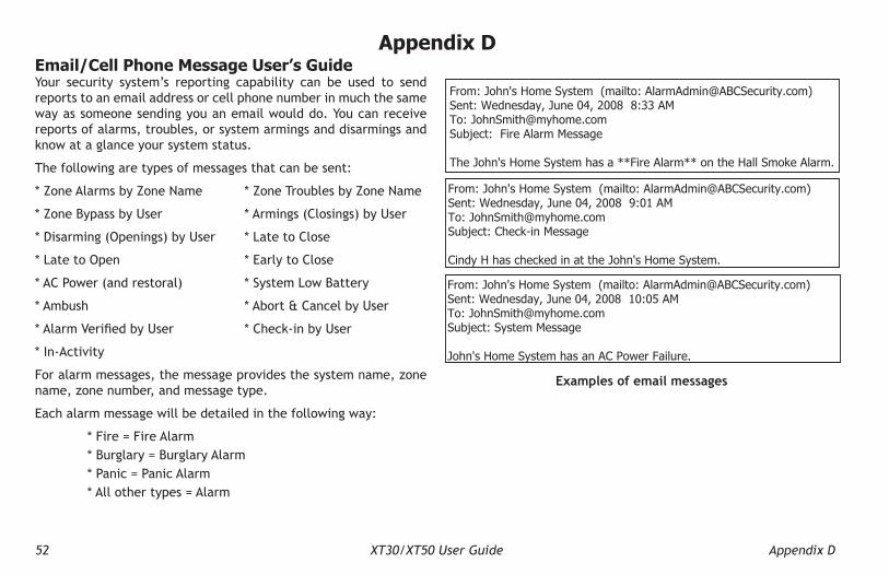
52 XT30/XT50 User Guide Appendix D
From: John's Home System (mailto: [email protected])Sent: Wednesday, June 04, 2008 8:33 AMTo: [email protected]: Fire Alarm Message
The John's Home System has a **Fire Alarm** on the Hall Smoke Alarm.
From: John's Home System (mailto: [email protected])Sent: Wednesday, June 04, 2008 9:01 AMTo: [email protected]: Check-in Message
Cindy H has checked in at the John's Home System.
From: John's Home System (mailto: [email protected])Sent: Wednesday, June 04, 2008 10:05 AMTo: [email protected]: System Message
John's Home System has an AC Power Failure.
Examples of email messages
Email/Cell Phone Message User’s GuideYour security system’s reporting capability can be used to send reports to an email address or cell phone number in much the same way as someone sending you an email would do. You can receive reports of alarms, troubles, or system armings and disarmings and know at a glance your system status.
The following are types of messages that can be sent:
* Zone Alarms by Zone Name * Zone Troubles by Zone Name
* Zone Bypass by User * Armings (Closings) by User
* Disarming (Openings) by User * Late to Close
* Late to Open * Early to Close
* AC Power (and restoral) * System Low Battery
* Ambush * Abort & Cancel by User
*AlarmVerifiedbyUser *Check-inbyUser
* In-Activity
For alarm messages, the message provides the system name, zone name, zone number, and message type.
Each alarm message will be detailed in the following way:
* Fire = Fire Alarm * Burglary = Burglary Alarm * Panic = Panic Alarm * All other types = Alarm
Appendix D

Appendix D XT30/XT50 User Guide 53
MyAccess™ Text Messaging CommandsYour system may be programmed to allow simple text messages to be sent to the security system and perform basic user operations. By texting a message from your cell phone or PDA, the following actions can be performed: Arm/Disarm, Cancel Alarm, turn Outputs On/Off, check Armed Status, Turn on and off lights, Lock and unlock doors, and Set the thermostat. .
The user that is texting commands to the system must have the authority to perform the commands as if it occurred at the keypad. The cell phone number and user numbers are setup during programming.After programming is completed, you will receive a welcome message text from the panel. Write down the phone number that the message comes from. This will be the number you use to text user operations to the system.
Note: When texting commands listed below, the commands can be either upper or lowercase.
A list of text commands can be obtained by texting “help” to the system phone number. Store this number in your cell phone and write the number on the Quick Reference Wallet Card located at the back of this manual.
Arming All Areas with Text Message Commands1. Text message your system panel with the following command:
• ARM, AWAY, or ALL: To arm all areas, depending on your system
Arming Partial Areas with Text Commands1. Text message your system panel with the following command:
• SLEEP: To arm the perimeter and interior of a Home/Sleep/Away system.
• HOME: To arm just the perimeter of a Home/Away/Sleep system.
• PERIM: To arm the perimeter of an All/Perimeter system.• ARM“AreaNumber”orARM“AreaName”:Toarmspecific
areas of an Area system.The NAME should identify the area name. The NUMBER should identify the area number. Names and numbers can be mixed, and a comma should separate the areas. If ARM is sent without any other words, all areas are armed.If the system is already armed, you can arm it again only if you are arming more areas than were originally armed.Disarming All Areas with Text Message Commands
1. Text message your system panel with the following command:• DISARM: To disarm all areas.
Disarming Partial Areas with Text Message Commands1. Text message your area system panel with the following
command:• DISARM “Area Number” or DISARM “Area Name”: To disarm
specificareas of an Area system.The NAME should identify the area name. The NUMBER should identify the area number. Names and numbers can be mixed, and a comma should separate the areas. If DISARM is sent without any other words, all areas will be disarmed.If the system is already disarmed, you will receive a message saying that the system is already disarmed.

54 XT30/XT50 User Guide Appendix D
Cancelling an Alarm with Text MessagingWhile the alarm bell or siren sounds, you may choose to cancel the alarm via text messaging.
1. If a valid alarm has not occurred, text CANCEL to disarm the system and cancel the alarm.
Turning Outputs On/Off/Momentary with Text MessagingAllows you to set the state of any output to on, off, or momentary.
1. To set the Output to ON Steady, text ON followed by the Output name or number. For example, to turn Output 3 on, you would text: ON Lights or ON 3.
2. To turn the Output to OFF, text OFF followed by the Output name or number. For example, to turn Output 3 off, you would text: OFF 3 or OFF LIGHTS.
3. To turn the Output to ON MOMENTARY (the output turns on for one second, and then off), text MOMENTARY followed by the Output name or number. For example, to turn Output 3 to momentary, you would text: MOMENTARY 3.
Turning Lights On/Off with Text MessagingAllows you to turn Z-Wave compatible lights on or off.
1. Toturnaspecificlighton,textTURNONfollowedbythelight name. For example, to turn Bedroom Light on, you would text: TURN ON BEDROOM LIGHT.
2. Toturnaspecificdimmerlightontoacertainlevel,textTURN ON followed by the light name and the dimmer level (1-10). For example, to turn Front Dimmer Light on to level 8, you would text: TURN ON FRONT DIMMER 8.
3. Toturnaspecificlightoff,textTURNOFFfollowedbythelight name. For example, to turn Bedroom Light off, you would text: TURN OFF BEDROOM LIGHT.
Locking/Unlocking Doors with Text MessagingAllows you to lock/unlock Z-Wave compatible doors.
1. To lock a specific lock, text LOCK followed by the lockname. For example, to lock the Front Door, you would text: LOCK FRONT DOOR.
2. Tounlockaspecificlock,textUNLOCKfollowedbythelockname. For example, to unlock the Front Door, you would text: UNLOCK FRONT DOOR.
Setting Thermostat with Text MessagingAllows you to set Z-Wave compatible thermostats with specifictemperatures.
1. To set the thermostat to Cool or Heat with a specifictemperature, text SET followed by the thermostat name followed by HEAT or COOL followed by the temperature. For example, to turn Main Thermostat on to COOL and 65°, you would text: SET MAIN THERMOSTAT COOL 65.
2. TosetthethermostattoAutowithspecificheatandcooltemperatures, text SET followed by the thermostat name followed by AUTO followed by the high temperature and the cool temperature. For example, to turn Main Thermostat on to AUTO with temperatures of 80° and 60°, you would text: SET MAIN THERMOSTAT AUTO 80 60.
3. To set the thermostat fan to Auto or On, text SET followed by the thermostat name followed by FAN followed by ON or AUTO. For example, to turn the Main Thermostat fan on, you would text: SET MAIN THERMOSTAT FAN ON.
Activating Favorites with Text MessagingAllows you to activate a Favorite of Z-Wave compatible devices.
1. To activate a Favorite, text ACTIVATE followed by the Favorite name. For example, to activate the Favorite named House Lights, you would text: ACTIVATE HOUSE LIGHTS.

Appendix D XT30/XT50 User Guide 55
Check Armed Status Text CommandAllows you to check the system armed status. If armed, the system will send a message stating the type of system you have followed by ON, such as ALL SYSTEM ON or HOME SYSTEM ON. If disarmed and no open zones, the system will send SYSTEM READY. If disarmed with open zones, it will send SYSTEM NOT READY followed by any open zones. A message of AC POWER TROUBLE will indicate when a power failure occurs. If in alarm or trouble, the system will send ALARM ON or TROUBLE ON followed by up to 3 zone names that are in alarm or trouble.
1. To receive the Armed Status, text: STATUS.Check Status of Lights, Doors, and Thermostats Text CommandAllows you to check the status of Z-Wave compatible lights, doors, and thermostats. The status shows which devices are currently on and any devices that are not responding.
1. To receive the Status of Z-Wave compatible lights, text: STATUS LIGHTS.
2. To receive the Status of Z-Wave compatible doors, text: STATUS DOORS.
3. To receive the Status of Z-Wave compatible thermostats, text: STATUS THERMOSTATS.
Subscribe to Text MessagesAllows you to set which text messages you receive from the panel. When your system is programmed to allow text messages, you will not be subscribed. To change your subscription status, follow the instructions below for desired messages.
1. Text the words SUBSCRIBE STATUS ALL to receive a text message for all arming and disarming occurrences in addition to any alarm.
2. Text the words SUBSCRIBE STATUS NONE to not receive a text message for arming and disarming occurrences, but still receive a text message for any alarm.
3. Text the words SUBSCRIBE STATUS OTHERS to receive a text message for all arming and disarming occurrences originating from other users, in addition to any alarm. This option will send a text message for all arming and disarming occurrences except for the ones you initiate at a keypad.
4. Text the word SUBSCRIBE to show the current subscription status and the available subscription options.

56 XT30/XT50 User Guide Appendix D
PhoneAccess™ User’s GuideFor your reference a PhoneAccess™ pocket guide is provided on the last page of this User’s Guide.
This exciting feature allows you to call your XT30/XT50 system from any outside touch-tone phone to arm and disarm protection areas or turn panel relay outputs on or off. Faulted zones force arm when the area arms.
How it worksNote: If your telephone system shares the phone line with a fax machine or answering machine, call and let the phone ring once, then hang up, and redial. The panel seizes the phone line so you can check system status and arm or disarm the system.
1. From a touch tone phone, call the system phone number. The XT30/XT50 answers and sounds a short ready tone.
2. You now have eight seconds to enter a valid Master user code. If the panel accepts the user code, you hear one or more beeps indicating the system current armed status.
Thefollowingtableidentifiesthebeepsandwhattheyrepresent.
If You will hearAll areas are armed 3 short beepsArea 1 (Perimeter) is armed 1 short beepAny area is armed 2 short beepsAll areas are disarmed 1 long beep
Note:Youcanalsofindoutthesystemarmedstatusbypressingthe * key at any time.
3. If the user code is not accepted by the panel, you hear four
short beeps. Check the user code and try again. After three unsuccessful attempts to enter the code, the panel locks out PhoneAccess™ until a valid user code is entered at a keypad.
4. Once the user code is accepted by the panel and the armed status is given, you can enter arming and disarming commands.
Press For this action You will hear# then 1 Arm all 3 short beeps# then 2 Arm Perimeter 1 short beep# then 3 Arm Perimeter/Interior 2 short beeps# then 0 Disarm all areas 1 long beep
#, 5, 4, 0, n* Toggles the output1 short beep = on 1 long beep = off 4 short beeps = restricted
* Use outputs 1, 2, 3 or 4 in place of n. Enter output descriptions below.
Note: Zones in a faulted condition are force armed when the area arms. 1. ________________________ 3. _________________________
2. ________________________ 4. _________________________

Appendix D XT30/XT50 User Guide 57
Common Keypad DisplaysListed below are several keypad messages you may see on the display. Follow the instructions in the Possible Solutions column to correct the problem. In many cases, you need to call a service person to correct the problem. Displays not discussed here indicate your service representative should be called.
Message Tone at Keypad Meaning Possible Solutions
INvALID CODE No The user code you entered is not recognized by the system. Check the user code and try again.
CLOSING TIME Yes The schedule has expired but the system has not been armed. Users still on the premises are reminded to arm the system or extend the schedule to a later time.
AC TROUBLE Yes The system is not getting proper AC power. Contact your service person if other electrical devices in your home are working.
BATTERY TROUBLE Yes The battery is either low or missing. Contact your service person.SYSTEM TROUBLE or SERvICE REqUIRED Yes There is a problem with one or more components in the system. Contact your service person.
SYSTEM BUSY No The system is performing another task with a higher priority. Wait a few moments for the system to complete the task.Contact your service person if the problem remains.
4-WIRE BUS TROUBLE NoThere is not a supervised device on the bus.
Contact your service person.The voltage is low or there is an open yellow wire.Two devices share the same address.
TRANSMIT FAIL Yes The panel has attempted to communicate with the central station ten times and has not succeeded.
Make sure your telephone line is working properly.Contact your service person if the problem remains.
NON-POLLED ADDRESS No Keypad is set to an invalid address. Contact your service person.
WIRELESS TROUBLE YesThe panel is unable to communicate with the wireless receiver. verify the receiver is properly connected to the panel.
verify the correct House Code is programmed in System Options.The wireless receiver is missing.
LOBAT Yes The Z-Wave Lock device has a low battery Contact your service person.
ZWAVE BUSY NoOnly one keypad at a time can access Z-Wave Setup. If a user attempts to access the menu from a second keypad Z-WAVE BUSY will be displayed.
The user must exit Z-Wave Setup in one keypad before accessing it in a second keypad.

58 XT30/XT50 User Guide Index
AALARM display 9Alarm Silence b, 7, 15, 17, 19All/Perimeter System 15
Alarm Silence 15, 17Arming 15Disarming 17, 19Shortcut Keys 16, 20
Aqualite™ Keypad 3Panic Keys 5
Area SystemArming 13Disarming 14Schedules 36
Arming 12All/Perimeter 15, 49, 50Area 13Home/Away 18, 50Instant 16Key Fob 13Shortcut Keys 16, 18, 20
Arming/Disarming Event Display 46
BBack Arrow (<—) Key 6Backlighting 6Bypassing zones 12, 18, 22, 25
CCancel Alarm 15, 17, 19, 54Central Station Monitoring 11Changing User codes 34Check-in Report to Pager 21, 23Clear Touch™ Keypad
Panic Icons 5
COMMAND 6, 11, 13, 14, 15, 22, 24, 25, 26, 27, 28, 29, 30, 31, 32, 33, 34, 35, 36, 37, 38, 45, 49, 50
Common Keypad Displays 53
DData Entry Keys 6Date and Time 38Disarming 14
All/Perimeter 16, 50Area 14Home/Away 19, 50Key Fob 13
Display Events 39, 45Arming and Disarming 46Supervisory 47System Monitor 47User Events 46, 47Wireless Events 47Zone Events 45, 46
EEasy Entry™ User’s Guide 49Easy Exit™ Shortcut Key 21Emergency Evacuation Plans 2ENTER CODE display 9Entering User Names 51Entry Delay 50Entry or Exit Zone 10Event Displays 45
Arming and Disarming 46Supervisory 47System Monitor 47User Check-In 46User Code Change 46
Wireless Jamming 47Wireless Trouble 47Zone Activity check 45Zone Bypass 45Zone Events 46
Exit Error 11Extending Schedules 37
FFalse Alarms 1Favorite 25, 26, 27, 28, 29, 36, 38, 41, 42,
54, 62
HHome/Away System 17
Arming 18Disarming 19Easy Exit™ Shortcut Key 19Shortcut Keys 18, 20
Home/Sleep/Away SystemAlarm Silence 19
How Your System Operates 12
IInstant Arming 16Instant Zone 10
KKeypad
2-Button Panic Keys 5Alarm 9Backlighting 6Displays 57Key Definitions 6LEDs 4Select Keys 4
Index

Index XT30/XT50 User Guide 59
Shortcut Keys 20SYSTEM TROUBLE 9Tones 7Types 3User Menu 1User Options 6volume 6Wireless Displays 8
Key Fob 8, 43, 48Arming 13Button Layout 8Button Programming 43Disarming 13LED Operation 48Status Table 48User Record 41
LLED Operation 4, 5, 48
OOutputs On Off 24
PPager Direct™ 52Permanent Schedules 36PhoneAccess™ 61Power LED 4, 5
RRequest Service? 39Resetting the Sensors 20, 24
SSchedules
Extending 37
Permanent 36Security System Terms 10Select Keys 4Sensor Reset 24Setting the Date and Time 38Shortcut Keys 16, 18, 19, 23, 24, 31
Arming Function 16, 18, 20Check-in (Latch Key) Report Function 21, 23Easy Exit™ Function 21Monitor (Chime) Function 20, 31Sensor (Fire) Reset Function 20, 24
Silencing an Alarm b, 7Status List 11Supervisory Event Display 47System Monitor Event Display 47System Ready/System Not Ready 16, 18System Setup Record 40System Test 32
TTest Your System Weekly 1Thinline™ Keypad 4, 5, 6, 7
LEDs 3Panic Keys 5
TROUBLE display 9Trouble Tone Response b, 7
UUser Check-In Event Display 46User Codes 33
Authority Levels 33Change Event Display 46Changing 34Deleting 34Names 33, 51Table 44
User Menu Options 22, 33
Vverify Alarm 15, 17, 19
WWireless 8, 48
Event Displays 47
ZZone 10Zone Activity Check 23Zone Event Display 46Z-Wave 14, 17, 19, 25, 26, 27, 28, 29, 30, 35,
54, 55, 57, 62Z-Wave devices 22, 25, 26, 27, 29, 30Z-Wave Favorite 25Z-Wave Setup 25, 57

60 XT30/XT50 User Guide

Quick Reference Wallet CardsPhoneAccess™ Quick Commands
Press For this action You will hear Note: Zones in a faulted condition are force armed when the area arms.
# then 1 Arm all 3 short beeps# then 2 Arm Perimeter 1 short beep# then 3 Arm Perimeter/Interior 2 short beeps# then 0 Disarm all areas 1 long beep
#, 5, 4, 0, n* Toggles the output1 short beep = on 1 long beep = off 4 short beeps = restricted
* Use outputs 1, 2, 3, or 4 in place of n. Enter output descriptions below.
1. ________________________ 3. _________________________
2. ________________________ 4. _________________________
MyAccess™ Text Messaging Quick CommandsPanel Phone Number: _______________________Text For this actionHELP List of text commandsARM, AWAY, ALL Arm all areas of your systemSLEEP Arm Perimeter and interior of a Home/Sleep/Away SystemHOME Arm perimeter of a Home/Sleep/Away SystemPERIM Arm perimeter of an All/Perimeter SystemARM NAME, # Armspecificareas(enterareaNAMEor#)ofanAreaSystemDISARM Disarm all areas of your systemDISARM NAME, # Disarmspecificareas(enterareaNAMEor#)ofanAreaSystemStatus To receive a status updateCancel Cancel alarm while the alarm bell or siren soundsON (Output name or #) TurnstheOutputspecifiedtoONSteadyOFF (Output name or #) TurnstheOutputspecifiedtoOFF
Cut along dotted lines.
Quick Reference Wallet CardsMyAccess™ Text Messaging Quick Commands
Panel Phone Number: _______________________Text For this actionHELP List of text commandsARM, AWAY, ALL Arm all areas of your systemSLEEP Arm Perimeter and interior of a Home/Sleep/Away SystemHOME Arm perimeter of a Home/Sleep/Away SystemPERIM Arm perimeter of an All/Perimeter SystemARM NAME, # Armspecificareas(enterareaNAMEor#)ofanAreaSystemDISARM Disarm all areas of your systemDISARM NAME, # Disarmspecificareas(enterareaNAMEor#)ofanAreaSystemSTATUS To receive a status updateCANCEL Cancel alarm while the alarm bell or siren soundsON (Output name or #) TurnstheOutputspecifiedtoONSteadyOFF (Output name or #) TurnstheOutputspecifiedtoOFF
Cut along dotted lines.
MyAccess™ Text Messaging Quick CommandsPanel Phone Number: ________________________
Area Names: 1. ________________________ 2. _________________________ 3. ________________________ 4. _________________________ 5. ________________________ 6. _________________________ Output Names: 1. ________________________ 2. _________________________ 3. ________________________ 4. _________________________ 31. ______________________ 32. _________________________ 33. ______________________ 34. _________________________ 41. ______________________ 42. _________________________ 43. ______________________ 44. _________________________

Cut along dotted lines.
Text For this actionOFF (Output name or #) TurnstheOutputspecifiedtoOFFMOMENTARY (Output name or #) TurnstheOutputspecifiedtoMOMENTARYZ-WAVE HELP List of Z-Wave compatible text commandsSTAUS LIGHTS To receive a status update for all light devicesTURN ON (Light name) TurnsthespecifiedlighttoONTURN ON (Light name) (Dimmer level) TurnsdimmerlightontoaspecifictempTURN OFF (Light name) TurnsthespecifiedlighttoOFFSTATUS LOCKS To receive a status update for all lock devicesLOCK (Lock name) LocksthespecifieddoorlockUNLOCK (Lock name) UnlocksthespecifieddoorlockSTATUS THERMOSTAT To receive a status update for the thermostatSET (thermometer name) COOL (Temp) SetthermostattoCoolwithspecifictempSET (thermometer name) HEAT (Temp) SetthermostattoHeatwithspecifictempSET (therm name) AUTO (Hi & Lo Temp) SetthermostattoAutowithspecifictempsACTIVATE (Favorite name) Activate the devices in the Favorite
Cut along dotted lines.
1. Call the panel phone number. The panel answers and sounds one short tone.
2. Enter your code within eight seconds. One beep means the code is good. Four short beeps means enter it again. You have three tries.
3. Youhave30secondstoenterthefirstcommand(seeotherside)and 30 seconds for each additional command.
If You will hearAll areas are armed 3 short beepsArea 1 (Perimeter) is armed 1 short beepAny area is armed 2 short beepsAll areas are disarmed 1 long beep
Text For this actionOFF (Output name or #) TurnstheOutputspecifiedtoOFFMOMENTARY (Output name or #) TurnstheOutputspecifiedtoMOMENTARYZ-WAVE HELP List of Z-Wave compatible text commandsSTATUS LIGHTS To receive a status update for all light devicesTURN ON (Light name) TurnsthespecifiedlighttoONTURN ON (Light name) (Dimmer level) TurnsdimmerlightontoaspecifictempTURN OFF (Light name) TurnsthespecifiedlighttoOFFSTATUS LOCKS To receive a status update for all lock devicesLOCK (Lock name) LocksthespecifieddoorlockUNLOCK (Lock name) UnlocksthespecifieddoorlockSTATUS THERMOSTAT To receive a status update for the thermostatSET (thermometer name) COOL (Temp) SetthermostattoCoolwithspecifictempSET (thermometer name) HEAT (Temp) SetthermostattoHeatwithspecifictempSET (therm name) AUTO (Hi & Lo Temp) SetthermostattoAutowithspecifictempsACTIVATE (Favorite name) Activate the devices in the Favorite
Z-Wave Device Names:
Device # Z-Wave Device Name


LT-0982 1.05 © 2014 Digital Monitoring Products, Inc.
15145


