24
Silent Power Series Generator Operator Manual Models WSP25 - WSP40 with DSE7320 Controller PN: 221228
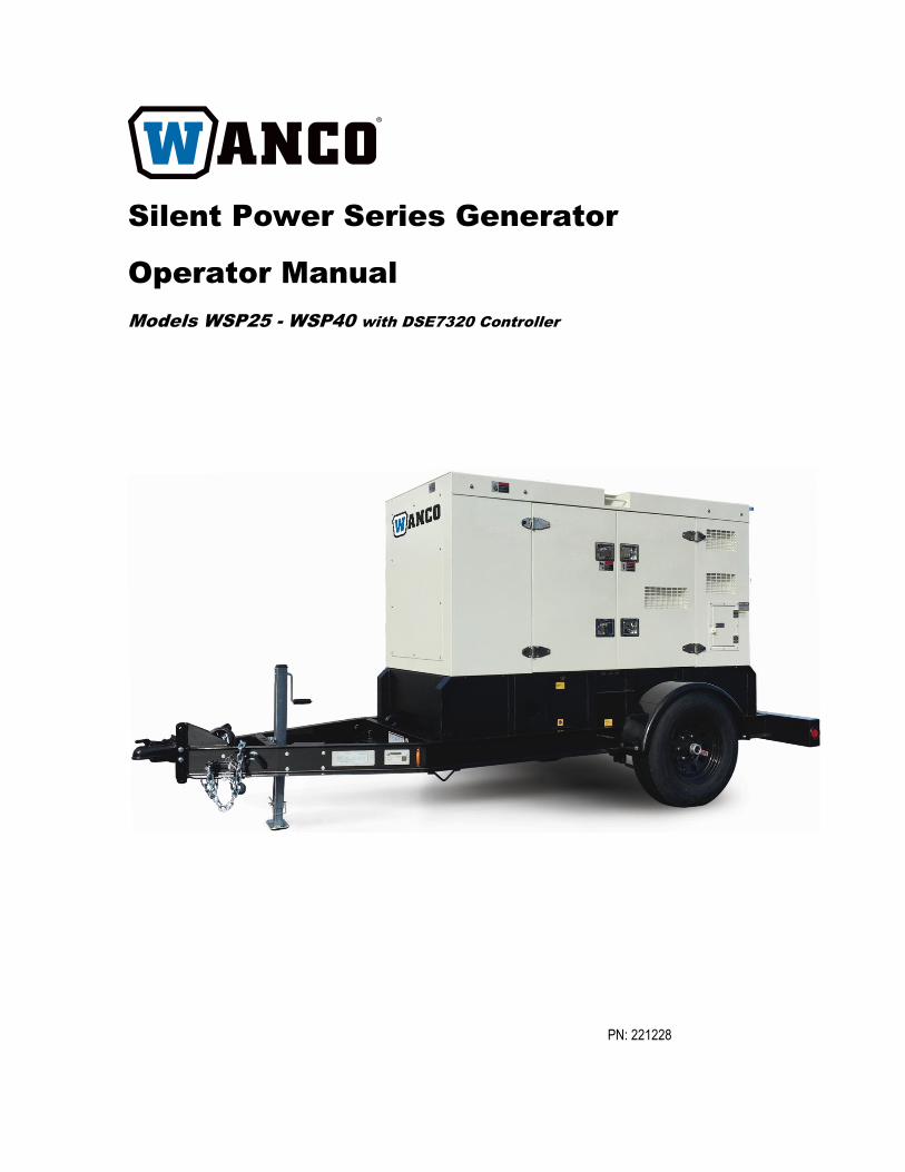
Silent Power Series Generator
Operator Manual
Models WSP25 - WSP40 with DSE7320 Controller
PN: 221228

Thank you for purchasing a Wanco Silent Power Series three-phase diesel generator set. This manual
contains important safety and operating information - please read the complete manual before attempting
to operate the generator.
All information in this publication is based on the latest product information available at the time of approval
for printing. We reserve the right to make changes at any time without notice.
No part of this publication may be reproduced without written permission.
Throughout this manual pay special attention to statements preceded by the following signal words:
Failure to properly follow these precautions is likely to result in property damage,
serious injury or death
Failure to properly follow these precautions can result in property damage,
serious injury or death
Indicates a possibility of personal injury or equipment damage if instructions are
not followed
Gives helpful information.
If you need assistance with your generator set, please contact our service department using the following
information:
Wanco Inc.
5870 Tennyson Street
Arvada, Colorado 80003
303-427-5700
fax 303-427-5725
www.wanco.com
If you need technical assistance with the alternator, please contact Mecc Alte directly:
Visit: www/meccalte.com – Support – Service Network – North America to locate a qualified service center
or contact the US office directly at:
MECC ALTE INC.
1229 ADAMS DRIVE - 60051
MCHENRY - ILLINOIS
USA
Tel. 815/344-0530 Fax 815/344-0535 email: [email protected]
If you need technical assistance with the Perkins engine, please contact your local Perkins Distributor or
call Wanco Inc.

Page | 3
CONTENTS
1. SAFETY INSTRUCTIONS ..................................................................... 4
2. MAJOR COMPONENT LOCATIONS ..................................................... 6
3. OPERATION .......................................................................................... 10
4. MAINTENANCE ..................................................................................... 12
5. TROUBLESHOOTING ........................................................................... 14
6. SPECIFICATIONS ................................................................................. 15
7. WIRING DIAGRAMS ............................................................................. 16
8. TOWING ................................................................................................ 18
Read and understand this Operator Manual before starting the generator. Failure to do so could
result in personal injury or equipment damage.
Refer to the Perkins Engine Operation & Maintenance Manual for important engine-specific
information.
Page | 4
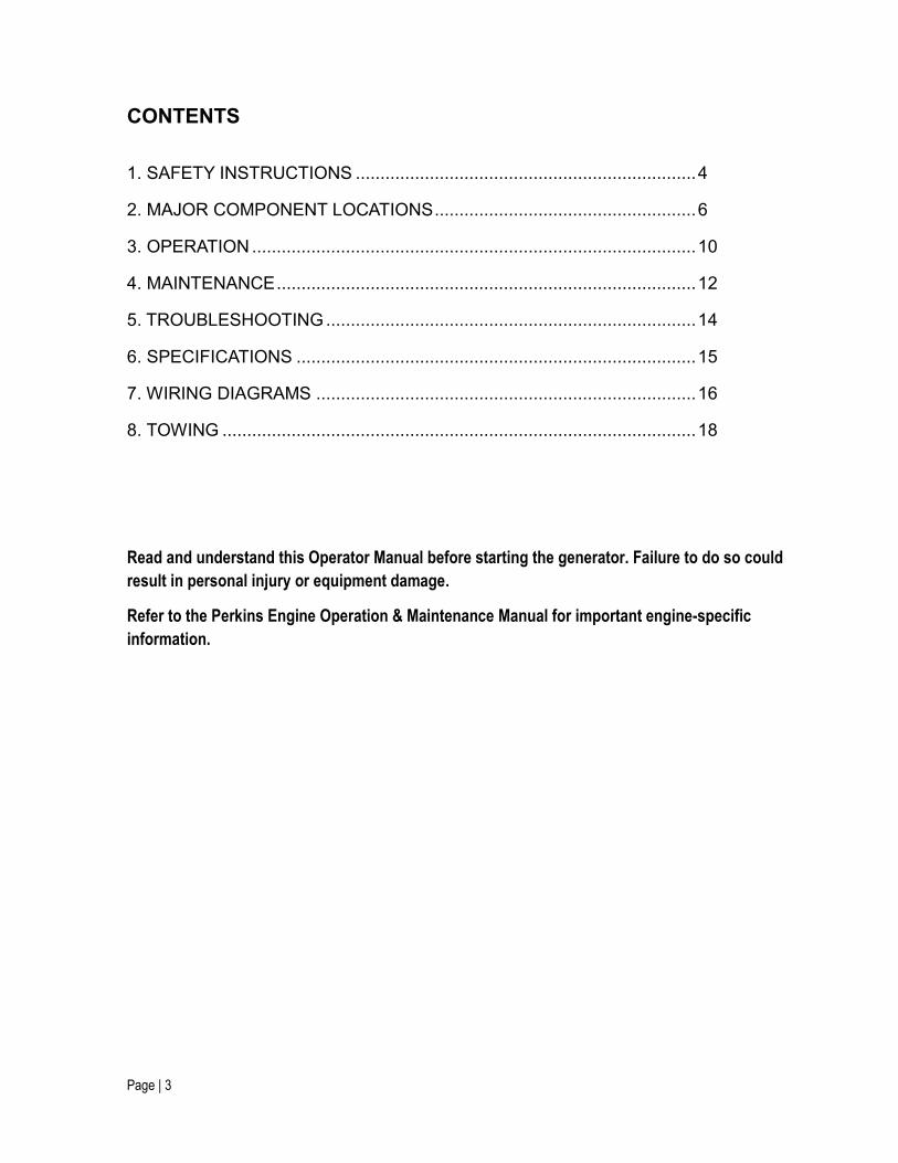
SAFETY INSTRUCTIONS
Electric Shock Hazard.
Contact with electric power lines will cause serious injury or death.
Contact with AC output terminals or other live electrical circuits on
this generator during operation will result in severe injury or death.
Only qualified service personnel should attempt to service the
generator electrical systems.
Explosion Hazard.
Keep Engine, fuel and other combustibles away from sparks, open
flame and burning objects.
Do not smoke near the generator.
Stop the engine before filling or draining the fuel tank.
Use only diesel fuel – do not fuel with gasoline.
Replace the fuel tank cap after refueling.
Do not use gasoline or other highly flammable solvents for cleaning.
Page | 5
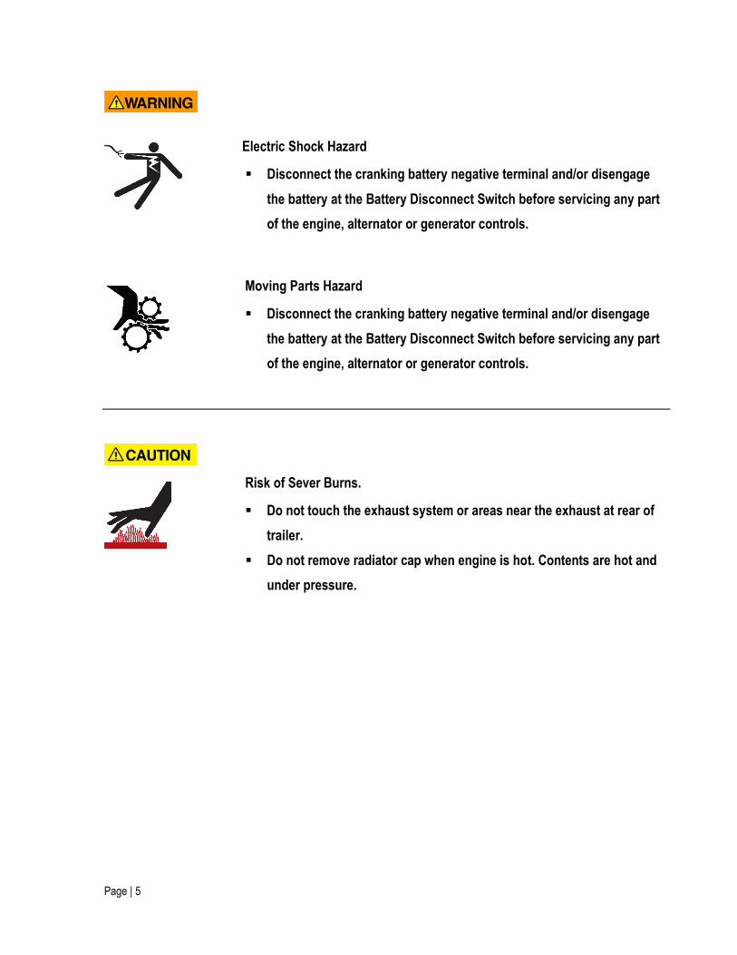
Electric Shock Hazard
Disconnect the cranking battery negative terminal and/or disengage
the battery at the Battery Disconnect Switch before servicing any part
of the engine, alternator or generator controls.
Moving Parts Hazard
Disconnect the cranking battery negative terminal and/or disengage
the battery at the Battery Disconnect Switch before servicing any part
of the engine, alternator or generator controls.
Risk of Sever Burns.
Do not touch the exhaust system or areas near the exhaust at rear of
trailer.
Do not remove radiator cap when engine is hot. Contents are hot and
under pressure.
Page | 6
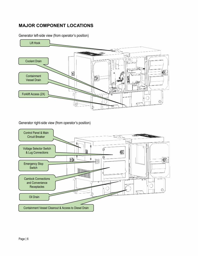
MAJOR COMPONENT LOCATIONS
Generator left-side view (from operator’s position)
Generator right-side view (from operator’s position)
Lift Hook
Coolant Drain
Containment
Vessel Drain
Forklift Access (2X)
Control Panel & Main
Circuit Breaker
Voltage Selector Switch
& Lug Connections
Emergency Stop
Switch
Camlock Connections
and Convenience
Receptacles
Oil Drain
Containment Vessel Cleanout & Access to Diesel Drain
Page | 7
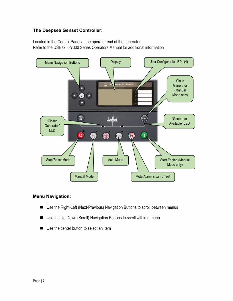
The Deepsea Genset Controller:
Located in the Control Panel at the operator end of the generator.
Refer to the DSE7200/7300 Series Operators Manual for additional information
Menu Navigation:
Use the Right-Left (Next-Previous) Navigation Buttons to scroll between menus
Use the Up-Down (Scroll) Navigation Buttons to scroll within a menu
Use the center button to select an item
Menu Navigation Buttons User Configurable LEDs (4)
Close
Generator
(Manual
Mode only)
Stop/Reset Mode
Manual Mode
Auto Mode
Mute Alarm & Lamp Test
Start Engine (Manual
Mode only)
Display
“Generator
Available” LED “Closed
Generator”
LED
Page | 8
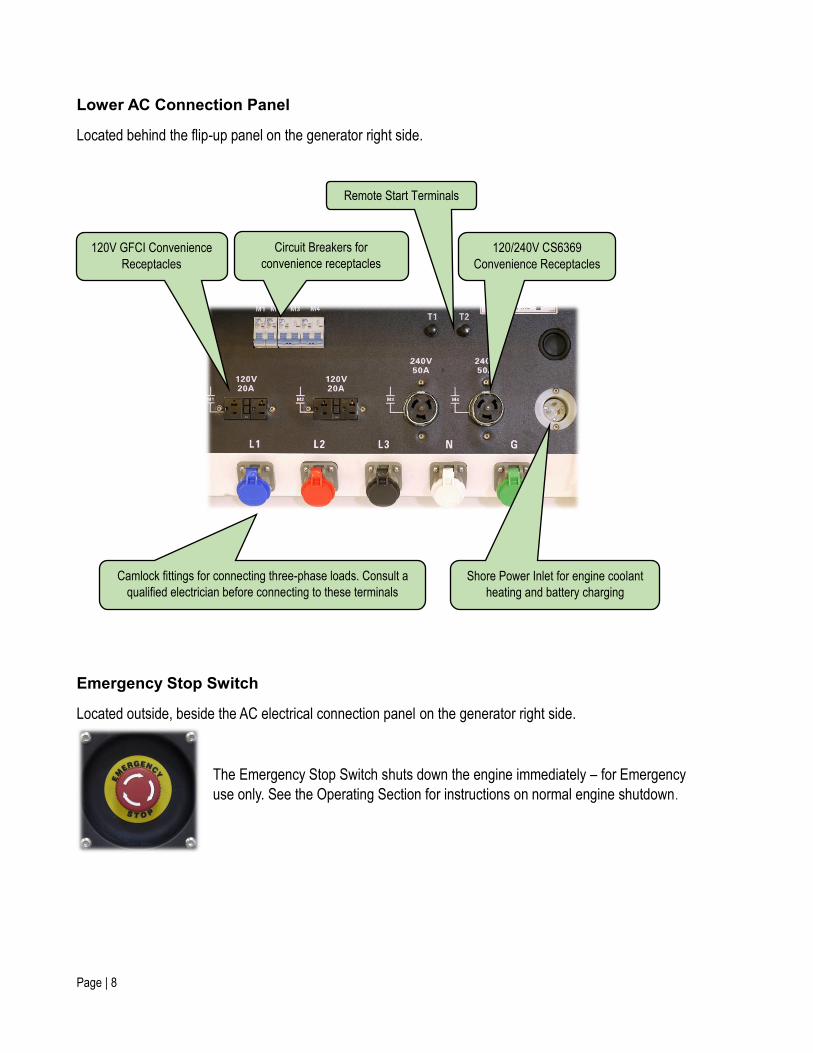
Lower AC Connection Panel
Located behind the flip-up panel on the generator right side.
Emergency Stop Switch
Located outside, beside the AC electrical connection panel on the generator right side.
The Emergency Stop Switch shuts down the engine immediately – for Emergency
use only. See the Operating Section for instructions on normal engine shutdown.
Circuit Breakers for
convenience receptacles
120V GFCI Convenience
Receptacles
Shore Power Inlet for engine coolant
heating and battery charging
Camlock fittings for connecting three-phase loads. Consult a
qualified electrician before connecting to these terminals
120/240V CS6369
Convenience Receptacles
Remote Start Terminals
Page | 9
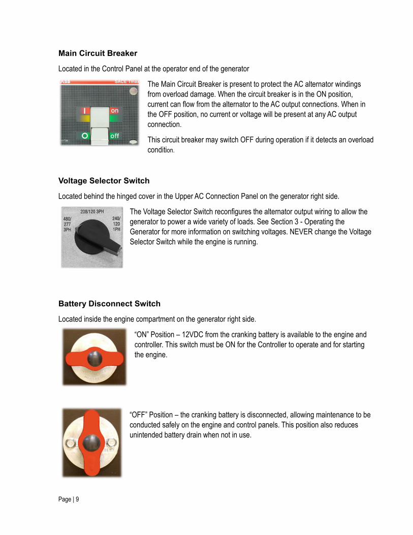
Main Circuit Breaker
Located in the Control Panel at the operator end of the generator
The Main Circuit Breaker is present to protect the AC alternator windings
from overload damage. When the circuit breaker is in the ON position,
current can flow from the alternator to the AC output connections. When in
the OFF position, no current or voltage will be present at any AC output
connection.
This circuit breaker may switch OFF during operation if it detects an overload
condition.
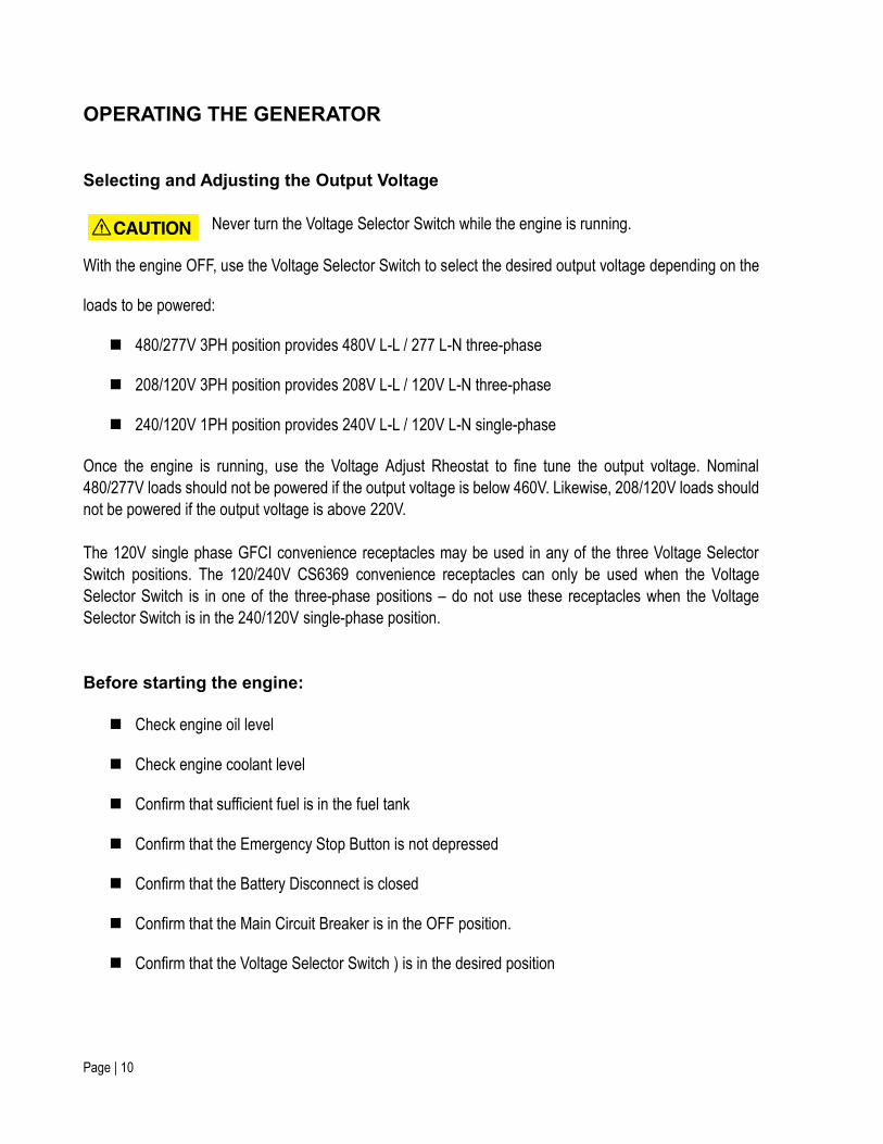
Voltage Selector Switch
Located behind the hinged cover in the Upper AC Connection Panel on the generator right side.
The Voltage Selector Switch reconfigures the alternator output wiring to allow the
generator to power a wide variety of loads. See Section 3 - Operating the
Generator for more information on switching voltages. NEVER change the Voltage
Selector Switch while the engine is running.
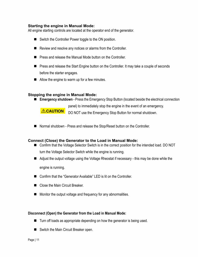
Battery Disconnect Switch
Located inside the engine compartment on the generator right side.
“ON” Position – 12VDC from the cranking battery is available to the engine and
controller. This switch must be ON for the Controller to operate and for starting
the engine.
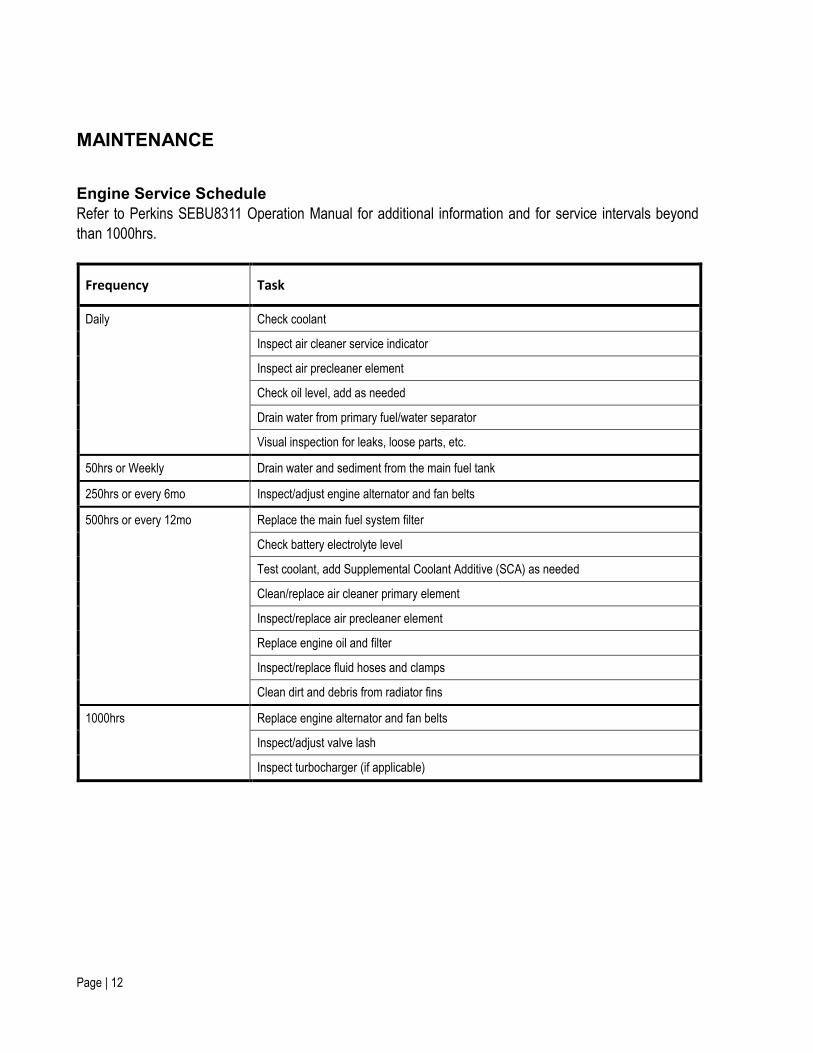
“OFF” Position – the cranking battery is disconnected, allowing maintenance to be
conducted safely on the engine and control panels. This position also reduces
unintended battery drain when not in use.
Page | 10
OPERATING THE GENERATOR Selecting and Adjusting the Output Voltage
Never turn the Voltage Selector Switch while the engine is running.
With the engine OFF, use the Voltage Selector Switch to select the desired output voltage depending on the
loads to be powered:
480/277V 3PH position provides 480V L-L / 277 L-N three-phase
208/120V 3PH position provides 208V L-L / 120V L-N three-phase
240/120V 1PH position provides 240V L-L / 120V L-N single-phase
Once the engine is running, use the Voltage Adjust Rheostat to fine tune the output voltage. Nominal
480/277V loads should not be powered if the output voltage is below 460V. Likewise, 208/120V loads should
not be powered if the output voltage is above 220V.
The 120V single phase GFCI convenience receptacles may be used in any of the three Voltage Selector
Switch positions. The 120/240V CS6369 convenience receptacles can only be used when the Voltage
Selector Switch is in one of the three-phase positions – do not use these receptacles when the Voltage
Selector Switch is in the 240/120V single-phase position.
Before starting the engine:
Check engine oil level
Check engine coolant level
Confirm that sufficient fuel is in the fuel tank
Confirm that the Emergency Stop Button is not depressed
Confirm that the Battery Disconnect is closed
Confirm that the Main Circuit Breaker is in the OFF position.
Confirm that the Voltage Selector Switch ) is in the desired position
Page | 11
Starting the engine in Manual Mode: All engine starting controls are located at the operator end of the generator.
Switch the Controller Power toggle to the ON position.
Review and resolve any notices or alarms from the Controller.
Press and release the Manual Mode button on the Controller.
Press and release the Start Engine button on the Controller. It may take a couple of seconds
before the starter engages.
Allow the engine to warm up for a few minutes.
Stopping the engine in Manual Mode: Emergency shutdown - Press the Emergency Stop Button (located beside the electrical connection
panel) to immediately stop the engine in the event of an emergency.
DO NOT use the Emergency Stop Button for normal shutdown.
Normal shutdown - Press and release the Stop/Reset button on the Controller.
Connect (Close) the Generator to the Load in Manual Mode: Confirm that the Voltage Selector Switch is in the correct position for the intended load. DO NOT
turn the Voltage Selector Switch while the engine is running.
Adjust the output voltage using the Voltage Rheostat if necessary - this may be done while the
engine is running.
Confirm that the “Generator Available” LED is lit on the Controller.
Close the Main Circuit Breaker.
Monitor the output voltage and frequency for any abnormalities.
Disconnect (Open) the Generator from the Load in Manual Mode:
Turn off loads as appropriate depending on how the generator is being used.
Switch the Main Circuit Breaker open.
Page | 12
MAINTENANCE
Engine Service Schedule
Refer to Perkins SEBU8311 Operation Manual for additional information and for service intervals beyond
than 1000hrs.
Frequency Task
Daily Check coolant
Inspect air cleaner service indicator
Inspect air precleaner element
Check oil level, add as needed
Drain water from primary fuel/water separator
Visual inspection for leaks, loose parts, etc.
50hrs or Weekly Drain water and sediment from the main fuel tank
250hrs or every 6mo Inspect/adjust engine alternator and fan belts
500hrs or every 12mo Replace the main fuel system filter
Check battery electrolyte level
Test coolant, add Supplemental Coolant Additive (SCA) as needed
Clean/replace air cleaner primary element
Inspect/replace air precleaner element
Replace engine oil and filter
Inspect/replace fluid hoses and clamps
Clean dirt and debris from radiator fins
1000hrs Replace engine alternator and fan belts
Inspect/adjust valve lash
Inspect turbocharger (if applicable)
Page | 13
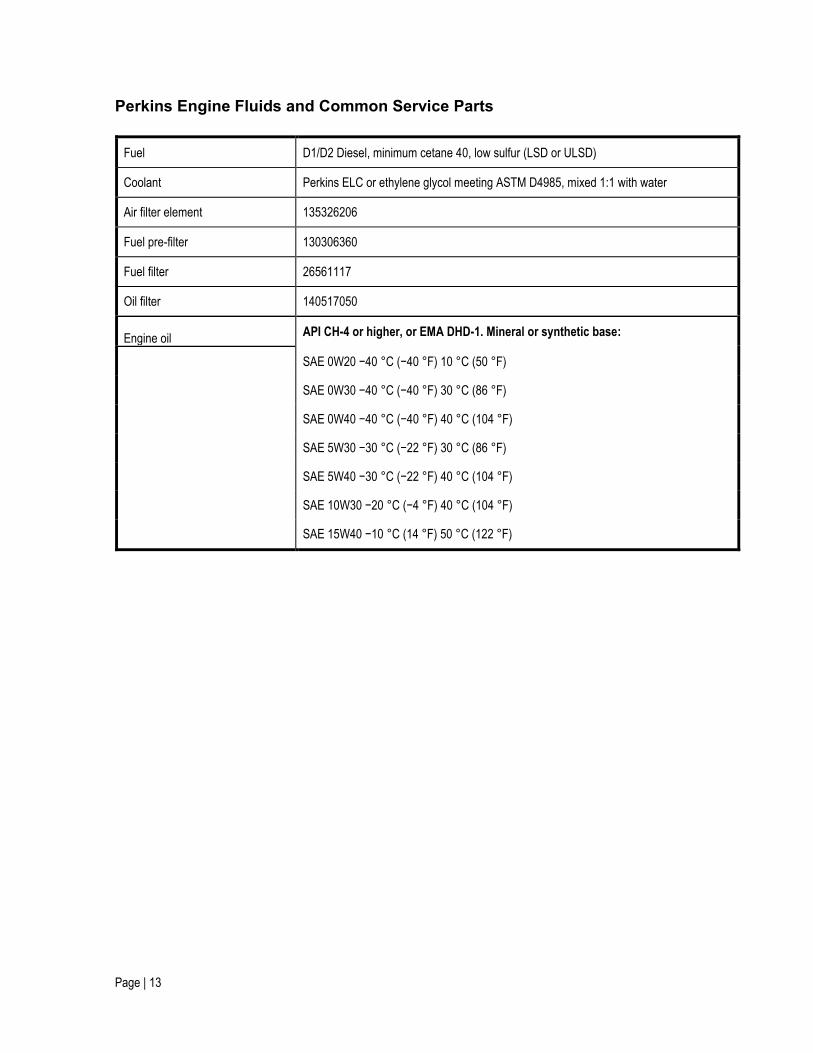
Perkins Engine Fluids and Common Service Parts
Fuel D1/D2 Diesel, minimum cetane 40, low sulfur (LSD or ULSD)
Coolant Perkins ELC or ethylene glycol meeting ASTM D4985, mixed 1:1 with water
Air filter element 135326206
Fuel pre-filter 130306360
Fuel filter 26561117
Oil filter 140517050
Engine oil API CH-4 or higher, or EMA DHD-1. Mineral or synthetic base:
SAE 0W20 −40 °C (−40 °F) 10 °C (50 °F)
SAE 0W30 −40 °C (−40 °F) 30 °C (86 °F)
SAE 0W40 −40 °C (−40 °F) 40 °C (104 °F)
SAE 5W30 −30 °C (−22 °F) 30 °C (86 °F)
SAE 5W40 −30 °C (−22 °F) 40 °C (104 °F)
SAE 10W30 −20 °C (−4 °F) 40 °C (104 °F)
SAE 15W40 −10 °C (14 °F) 50 °C (122 °F)
Page | 14
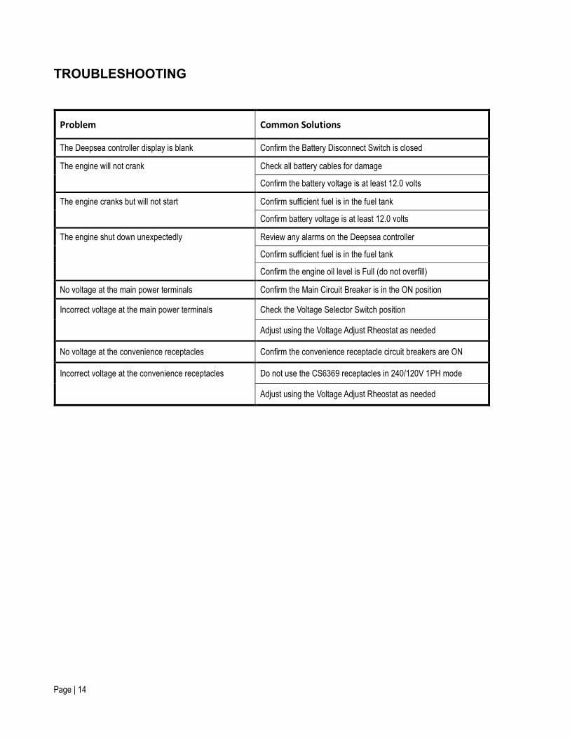
TROUBLESHOOTING
Problem Common Solutions
The Deepsea controller display is blank Confirm the Battery Disconnect Switch is closed
The engine will not crank Check all battery cables for damage
Confirm the battery voltage is at least 12.0 volts
The engine cranks but will not start Confirm sufficient fuel is in the fuel tank
Confirm battery voltage is at least 12.0 volts
The engine shut down unexpectedly Review any alarms on the Deepsea controller
Confirm sufficient fuel is in the fuel tank
Confirm the engine oil level is Full (do not overfill)
No voltage at the main power terminals Confirm the Main Circuit Breaker is in the ON position
Incorrect voltage at the main power terminals Check the Voltage Selector Switch position
Adjust using the Voltage Adjust Rheostat as needed
No voltage at the convenience receptacles Confirm the convenience receptacle circuit breakers are ON
Incorrect voltage at the convenience receptacles Do not use the CS6369 receptacles in 240/120V 1PH mode
Adjust using the Voltage Adjust Rheostat as needed
Page | 15
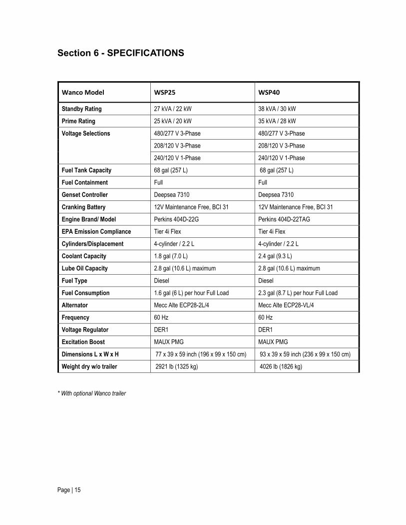
Section 6 - SPECIFICATIONS
Wanco Model WSP25 WSP40
Standby Rating 27 kVA / 22 kW 38 kVA / 30 kW
Prime Rating 25 kVA / 20 kW 35 kVA / 28 kW
Voltage Selections 480/277 V 3-Phase 480/277 V 3-Phase
208/120 V 3-Phase 208/120 V 3-Phase
240/120 V 1-Phase 240/120 V 1-Phase
Fuel Tank Capacity 68 gal (257 L) 68 gal (257 L)
Fuel Containment Full Full
Genset Controller Deepsea 7310 Deepsea 7310
Cranking Battery 12V Maintenance Free, BCI 31 12V Maintenance Free, BCI 31
Engine Brand/ Model Perkins 404D-22G Perkins 404D-22TAG
EPA Emission Compliance Tier 4i Flex Tier 4i Flex
Cylinders/Displacement 4-cylinder / 2.2 L 4-cylinder / 2.2 L
Coolant Capacity 1.8 gal (7.0 L) 2.4 gal (9.3 L)
Lube Oil Capacity 2.8 gal (10.6 L) maximum 2.8 gal (10.6 L) maximum
Fuel Type Diesel Diesel
Fuel Consumption 1.6 gal (6 L) per hour Full Load 2.3 gal (8.7 L) per hour Full Load
Alternator Mecc Alte ECP28-2L/4 Mecc Alte ECP28-VL/4
Frequency 60 Hz 60 Hz
Voltage Regulator DER1 DER1
Excitation Boost MAUX PMG MAUX PMG
Dimensions L x W x H 77 x 39 x 59 inch (196 x 99 x 150 cm) 93 x 39 x 59 inch (236 x 99 x 150 cm)
Weight dry w/o trailer 2921 lb (1325 kg) 4026 lb (1826 kg)
* With optional Wanco trailer
Page | 16
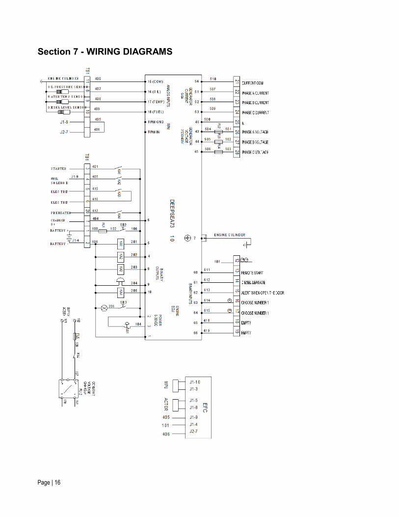
Section 7 - WIRING DIAGRAMS
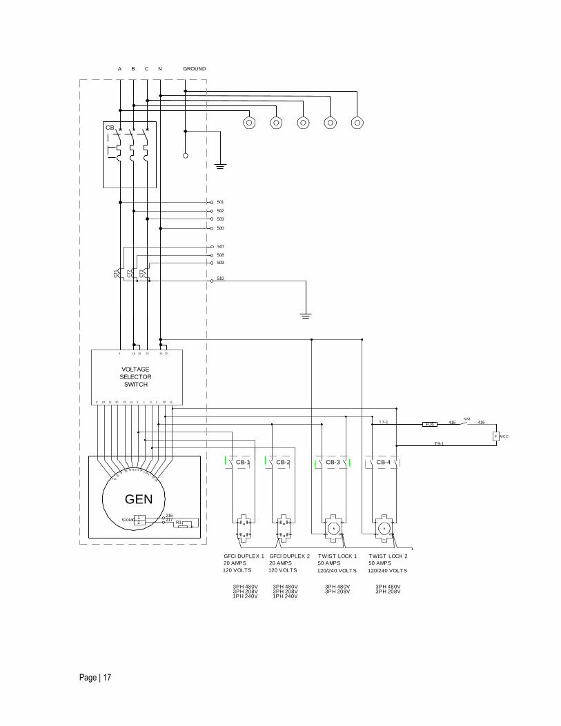
Page | 17
503
CT3
CT2
CT1
508
509
507
501
502
510
500
VOLTAGE
SELECTOR
SWITCH
GFCI DUPLEX 1
20 AMPS
120 VOLTS
GFCI DUPLEX 2
20 AMPS
120 VOLTS
TWIST LOCK 1
50 AMPS
120/240 VOLTS
TWIST LOCK 2
50 AMPS
120/240 VOLTS
3PH 480V3PH 208V1PH 240V
3PH 480V3PH 208V1PH 240V
3PH 480V3PH 208V
3PH 480V3PH 208V
217216
2SX440
1R1
KA3415 416
T9-1
F MC C B
T7-1FU6
GEN
CB
T3
T6T5
T2 T4T1T12
T7T10
T9T8
T11
23 11 20 13 1 2 28 12
103 19 25
H
H N
N H
H N
N Y
W GRD
X Y
W GRD
X
CB-1 CB-2 CB-3 CB-4
3 88 25
2215
NA CB GROUND
Page | 18
Section 8 - TOWING
Check tires, wheels, and axle lock:
Failure to properly follow these precautions can result in property damage, serious
injury or death
Check tires for wear. Replace worn tires.
Ensure tires are inflated to the proper pressure.
Verify all wheel lugs are in place and tightened. Do not tow the trailer if a wheel lug is missing.
Check the drawbar, tow hitch, and safety chains:
Failure to properly follow these precautions can result in property damage, serious
injury or death
Ensure the tow hitch on the tow vehicle is rated for weight equal to or greater than the genset gross
vehicle weight rating (GVWR). The GVWR is listed on the vehicle identification tag.
Ensure the tow hitch on the tow vehicle and the drawbar hitch on the trailer are compatible.
Inspect the tow hitch and drawbar hitch for wear and damage. Replace or repair if necessary.
If the trailer has a removable drawbar, ensure the drawbar is attached securely to the trailer frame
with two sets of bolts, washers, and nuts. The bolts should engage the drawbar and the nuts should
be tight.
Lower the drawbar jack into the down position by pulling the jack locking pin and rotating the jack
downward. Release the pin and continue rotating the jack until it is vertical. When the jack is properly
set, the locking pin snaps into position with an audible “click.” Use the hand-crank on the jack to
lower the wheel to the ground.
Verify the trailer’s four corner leveling jacks (if equipped) are in the up position and secured with their
locking pins. To raise the leveling jacks, use the hand-crank on each jack to raise the jack foot off the
ground, then pull the jack locking pin and rotate the jack upward. Release the pin and continue
rotating the jack until it is horizontal and the pin reengages with an audible “click.”
Use the drawbar jack to raise the front of the trailer and set the drawbar hitch on the tow vehicle
hitch. Ensure the coupling is properly engaged and locked.
Page | 19
Raise, rotate, and lock the drawbar jack in the up or horizontal position.
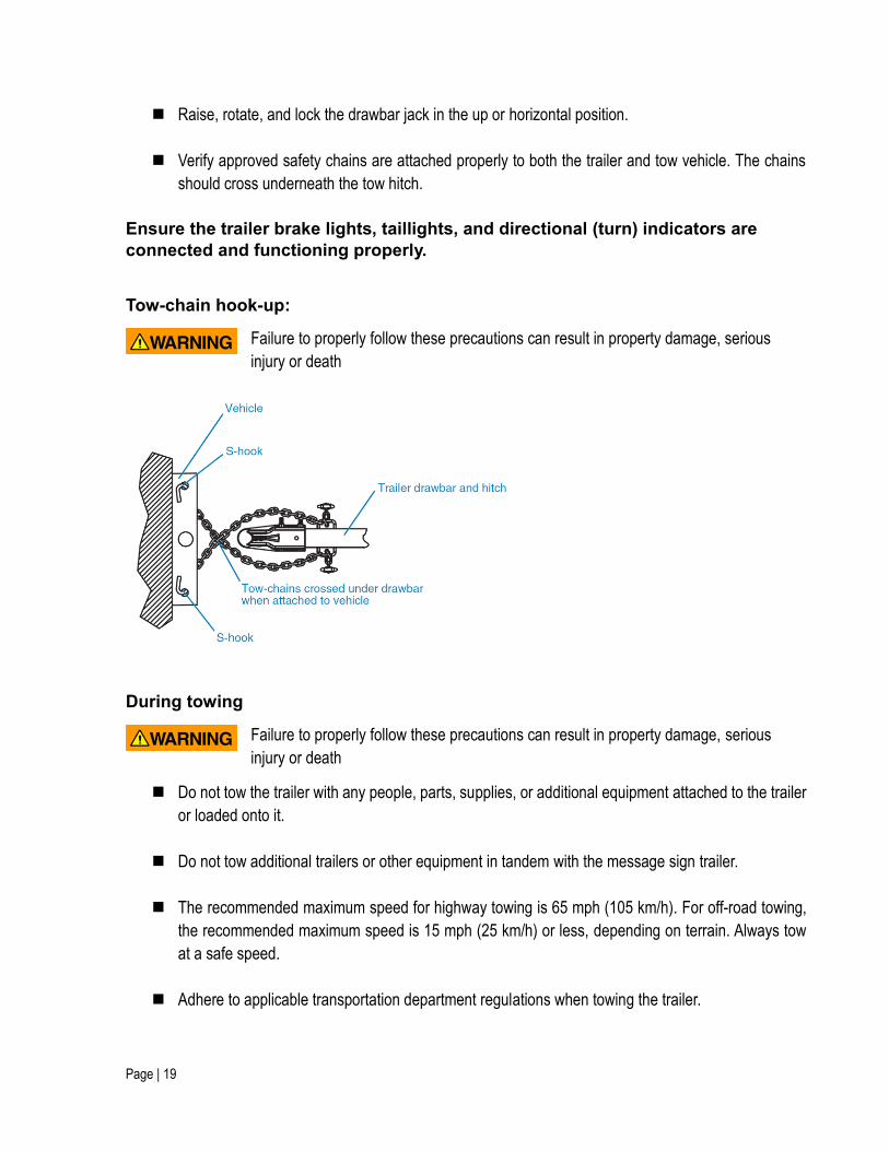
Verify approved safety chains are attached properly to both the trailer and tow vehicle. The chains
should cross underneath the tow hitch.
Ensure the trailer brake lights, taillights, and directional (turn) indicators are
connected and functioning properly.
Tow-chain hook-up:
Failure to properly follow these precautions can result in property damage, serious
injury or death
During towing
Failure to properly follow these precautions can result in property damage, serious
injury or death
Do not tow the trailer with any people, parts, supplies, or additional equipment attached to the trailer
or loaded onto it.
Do not tow additional trailers or other equipment in tandem with the message sign trailer.
The recommended maximum speed for highway towing is 65 mph (105 km/h). For off-road towing,
the recommended maximum speed is 15 mph (25 km/h) or less, depending on terrain. Always tow
at a safe speed.
Adhere to applicable transportation department regulations when towing the trailer.

Page | 20
After towing
After towing, unhook the tow chains from the tow vehicle, then use the drawbar-mounted jack to raise the
drawbar and release the drawbar hitch from the tow vehicle. Pull the vehicle away from the message sign
trailer when ready.


