18
Made in Germany Silent TS Nr. 2921-0050 / 2921-1050 2010-07 21-9191 A Ideas for dental technology

Made in Germany
Silent TSNr. 2921-0050 / 2921-1050
2010
-07
21-
9191
A
Ideas for dental technology


2
3
5 6
7 8
1
4

9 10
11 12
13 14
15 16

17 18
19 20
21 22
23 24

26
27 28
29
31
25
30

EN- 1 -
IntroductionWe are pleased with your decision to purchase Silent TS laboratory dust extractor. This device sets a new standard with regard to functionality, performance, and ergonomics.
Please read the following operating instruc-tions carefully and observe the information they contain in order to ensure a long and trouble-free service life.
SymbologyThe following symbols are employed in these instructions and on the unit itself:
Danger This indicates a direct risk of injury.
Electrical current This indicates a hazard due to electrical current.
Attention Failure to observe the associated informati-on can result in damage to the unit.
Note This provides the operator with useful infor-mation to make working with the unit easier.
Only intended for indoor use.
Before opening the unit, disconnect it from the mains power supply by unplugging the power cord from the wall outlet.
Burn hazard Hot surface or objects.
Observe the operating instructions.
Other symbols are explained as they occur.
Silent TSNr. 2921-0050 / 2921-1050
ENGLISH
Introduction ........................................................1Symbology .........................................................1Information for Operators ..................................2Operating Instructions1. Setup and Commissioning ...........................2
1.1 Setup ............................................................ 21.2 Connection to the Extraction Point ............... 21.3 Electrical Connection ................................... 21.4 Connecting electrical equipment .................. 2
2. Operation .....................................................32.1 Operating Elements .................................... 32.2 Switching the Unit ON / OFF ........................ 32.3 Adjusting and Displaying the
Extraction Force ........................................... 32.4 Continuous Operation ................................. 32.5 Automatic Mode ........................................... 32.6 Adjusting the Automatic Start Feature .......... 42.7 "Change Filter" - Indicator ............................ 4
2.7.1 Adjust the sensitivity of the „Replace filter“ indicator. ................................................................ 4
2.7.2 Activating / deactivating the „Replace filter“ indicator tone ......................................................... 4
3. Cleaning / Maintenance ...............................43.1 Seals ............................................................ 43.2 Replacing the Dust Bag ............................... 53.3 Filters ........................................................... 5
3.3.1 Replacing the Fine Particle Filter .......................... 53.3.2 Replacing the Exhaust Filter ................................. 53.3.3 Replacing the Electronics Filter ............................. 5
3.4 Fuses ........................................................... 53.5 Self-diagnosis ............................................... 63.6 Replacing the Suction Turbine ..................... 63.7 Replacing the Exhaust Air Labyrinth ............ 6
4. Spare Parts ..................................................65. Standard Delivery ........................................66. Delivery Versions .........................................77. Accessories ..................................................78. Error List ......................................................7Information for OperatorsA. Application Area ...........................................9
A.1 Proper Use ................................................... 9A.2 Ambient Conditions
(in accordance with DIN EN 61010-1) .......... 9B. Hazard and Warning Information .................9C. Authorised Individuals ................................10D. Preparations Prior to Starting .....................10
D.1 Connecting the Dust Extractor ................... 10D.2 Connecting a Dust-Generating Device ....... 11
E. Repairs .......................................................11F. Disposal Information ..................................11
F.1 Disposing of Consumables ........................ 11F.2 Disposing of the Unit .................................. 11
F.3 Disposal instructions for countries in the EU 11G. Technical Specifications .............................11H. Liability Exclusion .......................................11I. Warranty.....................................................12
Content

EN - 2 -
Information for Operators Using these operating instructions as a
starting point, instruct all operators of the unit with regard to the area of application, the possible hazards during operation, and the proper operation of the dust extractor.
Please have these operating instructions readily available for the operators.Additional information can be found in the Section, “Information for Operators”, at the end of these instructions.
Operating Instructions
1. Setup and Commissioning
1.1 SetupRemove the unit and all accessories from the ship-ping package.Inspect the delivery for completeness (refer to the “Standard Delivery” Section).The unit is fully operational upon delivery.
Select a setup location for the Silent TS where the exhaust air vent is not blocked.
Where the unit is to be installed in a cabinet, an opening with the following minimum dimensions must be provided:
• Circular opening: Diameter at least 120 mm• Rectangular opening: At least 170 x 65 mm.
The Silent TS is a free-standing unit intended to be set up on the floor (e.g., under a workbench).
Particularly after installation of the roller set (refer to the accessories list), the dust extractor may only be operated if it is standing on the floor.
1.2 Connection to the Extraction Point
Use the included suction hose to connect the unit to the extraction point.• Push the suction hose onto the extractor connec-
tion fitting on the dust extractor (fig. 1).• Connect the suction hose to the desired extraction
point (e.g., Dustex master plus, extractor clamp, etc.).
With the aid of an extractor switch or a Y-junction it is possible to connect up to two suction points, or if ne-cessary, use a universal adapter for connector tubes (see accessories).
Never operate the Silent TS without a suc-tion hose.
Avoid steep pitches or hanging points along the hose path. Never kink the hose and make sure it is never stretched or under tension when connected.
1.3 Electrical Connection Before connecting the unit to the wall
outlet, make sure the voltage information on the nameplate corresponds to your local power supply.
Arrange conducting parts (mains outlets, plugs and couplings) and install extension cord such that the protection class (IP) is retained.
Unroll the power cord.• Press the OFF switch (fig. 2A).• Plug the power cord into the wall outlet (fig. 3).•
The Silent TS is now ready for continuous operation.
1.4 Connecting electrical equipment
Electronic equipment (electrical dust-generating equipment) can be connected to the Silent TS at the coupler socket at the back of the machine (N, fig. 4).In the automatic mode, extraction starts automatically when a connected electric device is switched on.Section D.2 at the end of these instructions offers information concerning electrical systems employing different power plug designs.
When connecting electrically operated equipment to the dust extractor, please ob-serve the operating instructions and safety information provided with the equipment.
The unit power outlet is to be used only for connecting electric, dust-generating de-vices to be operated in conjunction with the dust extractor.
The unit power outlet is live once the Silent TS has been connected to the power supply – even when the Silent TS is switched off. This allows connected devices to be oper-ated without extraction for brief periods.
Power consumption of all devices con-nected to the unit power outlet may not exceed the rated value printed next to the unit power outlet.

EN- 3 -
2. Operation
2.1 Operating Elements Refer also to fig. 4, 5
(A) OFF switch
(B) ON switch
(C) Automatic mode LED indicator
(D) Continuous / automatic operating mode selector switch
(E) Continuous mode LED indicator
(F) Extraction force / activation sensitivity adjustment switch
8 (G) Extraction power / activation sensitivity display
(H) Extraction force / activation sensitivity adjustment switch
(K) "Change Filter" LED indicator
(L) Mains fuse (fig 4)
(M) Motor protection switch (fig. 4)
(N) Unit plug socket (fig. 4)
2.2 Switching the Unit ON / OFF
The Silent TS is switched on at the ON switch (B) (fig. 2b), and off at the OFF switch (A) (fig. 2a).Extraction starts and stops in conjunction with the selected operating mode (continuous operation or automatic operation).
The equipment‘s operating state is saved once the suction unit has been operating for longer than approx. 5 sec.
2.3 Adjusting and Displaying the Extraction Force
The suction performance of the Silent TS can be adjusted in 4 stages by the buttons (F) and (H). This permits the unit’s performance to be precisely mat-ched to different types of materials being extracted.The extraction force setting is shown on the display (G).
Increase the extraction force.
Decrease the extraction force.
2.4 Continuous Operation Continuous operation LED (E)
In the continuous operation mode, the extractor will begin running as soon as it is switched on, regardless of other electrical equipment which may or may not be connected.The operating mode selector switch (D) is used to switch between the “continuous” and “automatic” operating modes.The selected operating mode is indicated by LED (C) or LED (E).Continuous operating mode selection:
Switch the • Silent TS on
LED - comes onContinuous operation has now been selected -
or
LED - comes onThe automatic mode has been selected. -Press the „D“ key -
LED - comes onContinuous operation has now been selected. -
The extractor will switch on• The extractor is started and stopped with the ON (B) and OFF (A) switches.
2.5 Automatic Mode Automatic Mode, LED (C).
In automatic operation suction only starts when the electric device connected is switched on responsible is operated.Selecting the automatic mode:
Switch the • Silent TS on (fig. 2b)
LED - comes onThe automatic mode has been selected. -
or
LED - comes onContinuous operation has now been selected -and the extractor starts.Press the „D“ key -
LED - comes onThe automatic mode has been selected. -
The extractor starts as soon as you begin operating the dust-generating device.After the dust-generating device is switched off, the Silent TS continues to run for approx. 5 sec., then stops automatically.
EN - 4 -
2.6 Adjusting the Automatic Start Feature
In the automatic mode, the Silent TS is switched on and off by an automatic start system.This automatic start feature reacts to the current con-sumed by an electronic equipment plugged into the unit power outlet (N, fig. 4).If the current exceeds the activation threshold set at the Silent TS, extraction starts. If the current drops below this activation threshold, extraction stops.
The factory set parameter for the start-up threshold enables the Silent TS to react cor-rectly for most electrical dental equiment. Should this not be the case for a particular piece of equipment (eg. a handpiece), then the start-up threshold can be adjusted ac-cordingly.
To change the activation threshold:1. Switch Silent TS on.2. Press and hold for 3 sec.;
LED - and flash.A “0” flashes on the display. -
3. Switch electronic equipment off. For units equip-ped with a standby mode, switch them to this mode (e.g., for units equipped with handpieces, only switch the controller on without activating the handpiece).
4. Press the key.A “1” flashes on the display. -
5. Switch the electrical appliance on, i.e. activate the hand piece at the speed at which the Silent TS is required to start up.
6. Press the keyAn audible signal confirms that the adjustment -has been successfully performed.
The Silent TS returns to the operating mode (conti-nuous or automatic operation) which was set for the automatic start function prior to the adjustment.
2.7 "Change Filter" - IndicatorLED (K) coming on indicates that either the dust bag or the fine particle filter needs to be replaced. An acoustic signal will also sound three times in this case. In this case, follow the instructions given in the “Cleaning/Maintenance” section to replace the dust bag or the fine particle filter.
If the dust extractor continues to be used after the “Change Filter” indicator goes on, it will automatically stop once the airflow drops below a predefined minimum value. The LED display blinks (K). The indicator can be turned off by switching the Silent TS OFF and ON, thus restarting extraction.
Operating the unit with a blocked filtration system can result in hazards and damage to the extractor. Filters must be replaced if the extractor stops due to a full filter.
2.7.1 ADJUST THE SENSITIVITY OF THE „REPLACE FILTER“ INDICATOR.
It may be necessary to reduce responsivi-ty if the suction support of the connected appliance has a smaller diameter than the Silent TS. (<< 32.5mm).
The „Replace filter“ sensitivity can be adjusted within limits.To do this:• Switch the Silent TS off;• Switch the Silent TS on, and in doing so keep the
button firmly pressed until the display begins to blink. (5=factory set parameter)
Press button • ,Reduce level of sensitivity, -„Change filter“ signal will appear later. -==> Dust bag will get very full -
Press button • ,Increase level of sensitivity, -„Change filter“ signal appears more quickly. -==> Dust bag will get less full -
Press button • ,Accoustic signal confirms successful -adjustment.
2.7.2 ACTIVATING / DEACTIVATING THE „REPLACE FILTER“ INDICATOR TONE
The „Replace filter“ indicator tone can be activated or deactivated.To do this:• Switch the Silent off;• While holding down the and keys, switch
the Silent back on and wait for the indicator toneBrief indicator tone: acoustic signal deactivated. -Longer indicator tone: acoustic signal active -
3. Cleaning / Maintenance Always unplug the unit from the wall outlet
before beginning any cleaning or mainte-nance tasks.
Examine the power cord regularly, but at least annually, for damage or signs of aging. Immediately replace damaged power cords.
3.1 SealsTo ensure the proper function of the dust extractor, it is vital that the following three seals:
• Profile seal on the dust drawer (fig. 12a);• V-ring seal on the dust drawer (fig. 12b);• Seal on the upper front panel (fig. 20);
are not damaged.Inspect these seals when replacing the associated filters and replace them if they are found to be damaged (refer to the spare parts list).

EN- 5 -
3.2 Replacing the Dust BagThe dust extractor may only be operated with a complete filtration system. The dust bag must be immediately replaced with a new one as soon as the “Change Filter” indicator goes on.
Failure to replace the dust bag may result in it’s rupturing. Depending on the material in the bag, this may lead to hazards for the operator. In addition, the dust extractor may be damaged.
• Pull the front panel forward and off (fig. 8).• Pull the dust drawer out towards the front
(fig. 9).• Leave the dust bag in the dust drawer and take it to
the disposal location.• Remove the dust bag from the drawer.• Take off protection film, cover filter opening
(fig. 10).• Dispose the dust bag accordingly.
Always comply with all local ordinances governing proper disposal and accident prevention! Depending on the filter contents, protective clothing may be required.
• Insert the new dust bag into the dust drawer, be-ing careful to ensure that the dust bag is properly aligned in the guide grooves and the glue lap faces up (fig. 11).
Use only original Renfert dust bags (refer to the spare parts list).
• Inspect the dust drawer seal for damage and replace it, as required (fig. 12a, b).
• Insert the dust drawer, making sure it is straight, and push it fully against its stops. Make sure the dust drawer is seated correctly on the guide (fig. 13).
• Install the front panel on the bottom hooks first (fig. 14), then push it into the upper lock bolts, pressing firmly until it locks in place (fig. 15).
3.3 Filters NEVER operate the dust extractor without
the complete filtration system.
3.3.1 REPLACING THE FINE PARTICLE FILTER
Examine the fine particle filter regularly, but at least annually, and replace it. It must always be replaced if the “Change Filter” indicator (K) continues to go on, despite the dust bag having been replaced.• Pull the front panel forward and off (fig. 16).• Turn the fine particle filter anticlockwise to release it
(fig. 17).• Pull the fine particle filter straight forwards and out
of the unit (fig. 18) and dispose of it properly. Always comply with all local ordinances
governing proper disposal and accident prevention! Depending on the filter contents, protective clothing may be required.
• Install a new fine filter and fully insert it over the holder bar (fig. 19).
Use only original Renfert fine particle filters (refer to the spare parts list).
• Turn the fine particle filter clockwise and hand-tight-en it in place (fig. 17).
• Inspect the seal on the front panel for damage and replace it, as required (fig. 20).
• Snap the front panel in place (fig. 21, 22).
3.3.2 REPLACING THE EXHAUST FILTER
The exhaust filter primarily traps particles rubbed off the suction turbine graphite brushes. The filter should be replaced annually:• Press on the four lock tabs on the filter cassette
and pull the cassette down and off the unit (fig. 23).
• Properly dispose of the filter and the filter cassette. Always comply with all local ordinances
governing proper disposal and accident prevention! Depending on the filter contents, protective clothing may be required.
• Insert a new filter mat in the filter cassette so that the smooth, compressed side of the filter mat faces down or outwards when the filter is installed.
• Install the new filter cassette on the exhaust air vent.
• Make sure the filter cassette is properly seated and locked in place on all four tabs.
Use only original Renfert exhaust filters (refer to the spare parts list).
3.3.3 REPLACING THE ELECTRONICS FILTER
Cooling air for the unit’s electronics passes through the electronics filter. The type of material trapped by the filter and the degree of contamination depend on the ambient laboratory conditions.The filter should be examined annually and replaced, as necessary:• Press on the two lock tabs on the filter cassette and
pull the cassette off towards the rear of the unit (fig. 24).
• Properly dispose of the filter and the filter cassette. Always comply with all local ordinances
governing proper disposal and accident prevention! Depending on the filter contents, protective clothing may be required.
• Install a new filter cassette and filter on the opening.
• Make sure the filter cassette is properly seated and locked in place on both tabs.
Use only original Renfert electronics filters (refer to the spare parts list).
3.4 FusesInstead, two device overload switches, (L, fig. 4) are provided to protect these units.Press the button to reset a switch which has tripped.

EN - 6 -
3.5 Self-diagnosisThe dust extractor is equipped with a self-diagnosis, which checks various functions and displays errors on the display (G).
Before the diagnosis takes place, insert a new dust bag and ensure that the fine filter is clean and the suction pipe is not blocked.
Activate the self-diagnosis:• Switch Silent TS off;• Press and hold the operating mode selector switch
(D) and switch Silent TS on (fig. 7a).• For approx. 3 sec.:
all LED displays are illuminated, -An „8“ is indicated in the display -The signalling device gives an acoustic signal. -
• A “d” appears on the display during the unit’s self-test (fig. 7b). During this time, the unit’s electronics check various internal elements and functions. The suction turbines will briefly run at Level 1 during this test phase.
• If no errors are detected, the Silent TS automatical-ly goes into the previously selected operating mode at the end of the self-test (after approx. 10 sec.).
• If an error is detected during the self-test, a flashing “E” will appear on the display, together with a number (1 to 3).
These indicate:E1: Airflow sensor fault; have the unit repaired.E2: Plug on grey motor wire out of its socket
(fig. 26a) or suction turbine fault. Replace suction turbine if necessary (refer to the spare parts list).
E3: Error in the electronics; have the unit repaired. In this case, the Silent TS remains in the
self-diagnosis mode until it is switched off at the OFF switch (A).
3.6 Replacing the Suction Turbine
The suction turbine is encased in an encapsulating housing to form a single unit, thus allowing it to be easily replaced without the need for any tools.
Before opening the unit, disconnect it from the mains power supply by unplugging the power cord from the wall outlet.
The motor may be hot. Allow the motor to cool off before proceeding.
The suction turbine may only be operated when it is installed in the unit. Only an authorized electrician may perform a func-tional inspection of or repair the unit.
• Turn the lock knob 90° anticlockwise (fig. 25).Remove the motor compartment cover.•
• Pull the plug on the grey motor wire out of its socket (fig. 26a).
• Loosen the two internal, grey knurled nuts (fig. 26b) and unscrew them approx. 1 cm. These knurled nuts do not need to be completely re-moved.
• Release the suction turbine by turning it anticlock-
wise, then pull it straight out towards the back (fig. 27).
• Install the new suction turbine (fig. 27) by pushing it in straight and turning it clockwise to lock it in place (fig. 28). The connecting wire should be on top (fig. 27a).
• Tighten the internal knurled nuts (fig. 26b).• Plug the motor wire into the socket (fig. 26a).• Check that the lock knob is in the open position
(vertical).Place the motor compartment cover on the motor • compartment. Two guide pins have been provided on the cover to assist in positioning it correctly.Turn the lock knob 90° clockwise (fig. 30).•
Always comply with all local ordinances governing proper disposal and accident prevention!
3.7 Replacing the Exhaust Air Labyrinth
Dust from the suction turbine graphite brushes also settles on the walls of the exhaust air labyrinth. Over time, the labyrinth will become discoloured.
Before opening the unit, disconnect it from the mains power supply by unplugging the power cord from the wall outlet.
Replacing the exhaust air labyrinth:• Turn the lock knob 90° anticlockwise (fig. 25).
Remove the motor compartment cover.• • Pull the exhaust air labyrinth out towards the back.• Install the new exhaust air labyrinth by pushing it
in straight, making sure it is properly seated. The openings in the exhaust air labyrinth must face towards the rear (fig. 29).
• Check that the lock knob is in the open position (vertical).Place the motor compartment cover on the motor • compartment. Two guide pins have been provided on the cover to assist in positioning it correctly.Turn the lock knob 90° clockwise (fig. 30).•
Always comply with all local ordinances governing proper disposal and accident prevention!
4. Spare PartsFor the order numbers of consumables and spare parts please refer to the spare parts list at the end of this manual.
5. Standard Delivery1 Silent TS laboratory dust extractor1 Operating instructions1 Suction hose1 Dust bag (properly installed in the dust drawer)1 Fine particle filter (properly installed)1 Hose fitting adapter 1 Y-junction1 Grounded wall plug (No. 2921-0050 only)
EN- 7 -
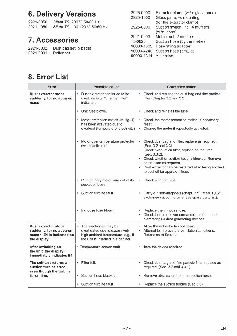
6. Delivery Versions2921-0050 Silent TS, 230 V, 50/60 Hz2921-1050 Silent TS, 100-120 V, 50/60 Hz
7. Accessories2921-0002 Dust bag set (5 bags)2921-0001 Roller set
2925-0000 Extractor clamp (w./o. glass pane)2925-1000 Glass pane, w. mounting
(for the extractor clamp)2926-0000 Suction switch, incl. 4 mufflers
(w./o. hose)2921-0003 Muffler set, 2 mufflers15-0823 Suction hose (by the metre)90003-4305 Hose fitting adapter90003-4240 Suction hose (3m), cpl90003-4314 Y-junction
8. Error ListError Possible cause Corrective action
Dust extractor stops suddenly, for no apparent reason.
• Dust extractor continued to be used, despite “Change Filter” indicator.
• Unit fuse blown.
• Motor protection switch (M, fig. 4) has been activated due to overload (temperature, electricity).
• Motor over-temperature protector switch activated.
• Plug on grey motor wire out of its socket or loose.
• Suction turbine fault
• In-house fuse blown.
• Check and replace the dust bag and fine particle filter (Chapter 3.2 and 3.3)
• Check and reinstall the fuse
• Check the motor protection switch, if necessary reset.
• Change the motor if repeatedly activated.
• Check dust bag and filter, replace as required.(Sec. 3.2 and 3.3)
• Check exhaust air filter, replace as required. (Sec. 3.3.2).
• Check whether suction hose is blocked. Remove obstruction as required.
• Dust extractor can be restarted after being allowed to cool off for approx. 1 hour.
• Check plug (fig. 26a).
• Carry out self-diagnosis (chapt. 3.5), at fault „E2“ exchange suction turbine (see spare parts list).
• Replace the in-house fuse.• Check the total power consumption of the dust
extractor plus dust-generating devices.
Dust extractor stops suddenly, for no apparent reason. E4 is indicated on the display.
• The electronics may be overheated due to excessively high ambient temperature, e.g., if the unit is installed in a cabinet.
• Allow the extractor to cool down.• Attempt to improve the ventilation conditions.
Refer also to Sec. 1.1
After switching on the unit, the display immediately indicates E4.
Temperature sensor fault• Have the device repaired•
The self-test returns a suction turbine error, even though the turbine is running.
• Filter full.
• Suction hose blocked.
• Suction turbine fault
• Check dust bag and fine particle filter, replace as required. (Sec. 3.2 and 3.3.1)
• Remove obstruction from the suction hose.
• Replace the suction turbine (Sec.3.6).
EN - 8 -
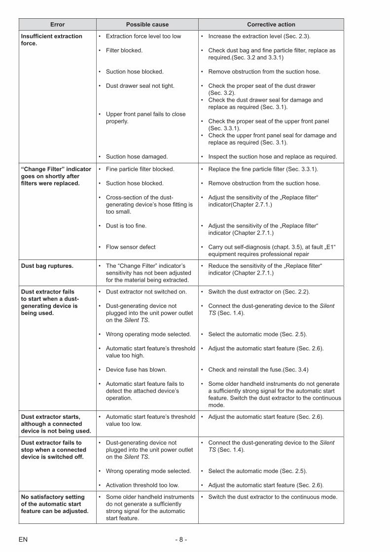
Error Possible cause Corrective action
Insufficient extraction force.
• Extraction force level too low
• Filter blocked.
• Suction hose blocked.
• Dust drawer seal not tight.
• Upper front panel fails to close properly.
• Suction hose damaged.
• Increase the extraction level (Sec. 2.3).
• Check dust bag and fine particle filter, replace as required.(Sec. 3.2 and 3.3.1)
• Remove obstruction from the suction hose.
• Check the proper seat of the dust drawer (Sec. 3.2).
• Check the dust drawer seal for damage and replace as required (Sec. 3.1).
• Check the proper seat of the upper front panel (Sec. 3.3.1).
• Check the upper front panel seal for damage and replace as required (Sec. 3.1).
• Inspect the suction hose and replace as required.
“Change Filter” indicator goes on shortly after filters were replaced.
• Fine particle filter blocked.
• Suction hose blocked.
• Cross-section of the dust-generating device’s hose fitting is too small.
• Dust is too fine.
• Flow sensor defect
• Replace the fine particle filter (Sec. 3.3.1).
• Remove obstruction from the suction hose.
• Adjust the sensitivity of the „Replace filter“ indicator(Chapter 2.7.1.)
• Adjust the sensitivity of the „Replace filter“ indicator (Chapter 2.7.1.)
• Carry out self-diagnosis (chapt. 3.5), at fault „E1“ equipment requires professional repair
Dust bag ruptures. • The “Change Filter” indicator’s sensitivity has not been adjusted for the material being extracted.
• Reduce the sensitivity of the „Replace filter“ indicator (Chapter 2.7.1.)
Dust extractor fails to start when a dust-generating device is being used.
• Dust extractor not switched on.
• Dust-generating device not plugged into the unit power outlet on the Silent TS.
• Wrong operating mode selected.
• Automatic start feature’s threshold value too high.
• Device fuse has blown.
• Automatic start feature fails to detect the attached device’s operation.
• Switch the dust extractor on (Sec. 2.2).
• Connect the dust-generating device to the Silent TS (Sec. 1.4).
• Select the automatic mode (Sec. 2.5).
• Adjust the automatic start feature (Sec. 2.6).
• Check and reinstall the fuse.(Sec. 3.4)
• Some older handheld instruments do not generate a sufficiently strong signal for the automatic start feature. Switch the dust extractor to the continuous mode.
Dust extractor starts, although a connected device is not being used.
• Automatic start feature’s threshold value too low.
• Adjust the automatic start feature (Sec. 2.6).
Dust extractor fails to stop when a connected device is switched off.
• Dust-generating device not plugged into the unit power outlet on the Silent TS.
• Wrong operating mode selected.
• Activation threshold too low.
• Connect the dust-generating device to the Silent TS (Sec. 1.4).
• Select the automatic mode (Sec. 2.5).
• Adjust the automatic start feature (Sec. 2.6).
No satisfactory setting of the automatic start feature can be adjusted.
• Some older handheld instruments do not generate a sufficiently strong signal for the automatic start feature.
• Switch the dust extractor to the continuous mode.

EN- 9 -
Error Possible cause Corrective action
Extraction briefly starts up when the unit is switched on.
• Activation sensitivity too low. • Adjust the automatic start feature (Sec. 2.6).
Panels covering the fine particle filter and the dust drawer are difficult to open.
• Lock bolts dirty. • Clean the lock bolts and lubricate them slightly, if required.
Information for OperatorsThe following information is intended to assist you, the operator, in safely working with the Silent TS in your laboratory.
Using these operating instructions as a starting point, instruct all operators of the unit with regard to the area of application, the possible hazards during operation, and the proper operation of the dust extractor.
Please have these operating instructions readily available for the operators.
A. Application AreaThe Silent TS is a workbench extractor used to ex-tract dusts such as occur in laboratories, e.g., dental labs.It is solely intended for commercial use in laboratories and not for private, household use.The Silent TS can be operated both manually as well as in conjunction with connected, electric, dust-gener-ating equipment.It is possible to connect one or two suction points to the extractor. The second suction point can be connected with a Y-adapter which is available as an accessory (see chapter „accessories“).
In order to protect the health of persons working in a dental laboratory, the law re-quires that specialised dust extractors must be used. National regulations state the MAK value - maximum concentration of suspended particles in the air. Find out about the legal national threshold value and the type of dust generated in your laboratory.
A.1 Proper UseProper use implies the extraction of dry, non-explo-sive dusts.Fire-promoting, easily flammable, flammable, or ex-plosive materials may not be extracted with the Silent TS.The extraction of liquids, smouldering, or burning materials is prohibited.Any other use is not „as intended“. The manufacturer shall not be liable for any damages resulting from any such other use.
The „use as intended“ includes compliance with the operating, servicing and preventive maintenance conditions defined by the manufacturer.
A.2 Ambient Conditions (in accordance with DIN EN 61010-1)
The unit may only be operated:• Indoors;• Up to an altitude of 2,000 m above sea level;• At an ambient temperature range between
5 - 40ºC [41 - 104ºF] *);• At a maximum relative humidity of 80% at 31ºC
[87.8ºF], dropping in a linear manner to 50% rela-tive humidity at 40ºC [104ºF] *);
• With mains power where the voltage fluctuations do not exceed 10% of the nominal value;
• Under contamination level 2 conditions;• Under over-voltage category II conditions;*) Between 5 – 30°C [41 – 86°F], the unit can be operated at
a relative humidity of up to 80%. At temperatures between 31 – 40°C [87.8 – 104°F], the humidity must decrease proportionally in order to ensure operational readiness (e.g., at 35°C [95°F] = 65% humidity; at 40°C [104°F] = 50% humidity). The unit may not be operated at temperatures above 40°C [104°F].
B. Hazard and Warning Information Only intended for indoor use. The unit is
only designed for dry applications and may not be operated or stored outdoors or under wet conditions.
The Silent TS laboratory dust extractor is an electric device and, as such, carries with it a certain inherent potential hazard. The unit may not be taken into service until any required alterations to comply with region-ally specific power plug configurations have been made. Such alterations may only be performed by a qualified electrician.
The unit may only be operated if the infor-mation on the nameplate conforms with the specifications of your local mains power supply.

EN - 10 -
The mains socket on the unit is only de-signed for the purposes specified in the Operating Instructions. Connecting other devices may cause material damage.Before connecting another device, turn off both the dust extractor and the other de-vice.Read the operating instructions of the other device and comply with the safety instruc-tions contained in the document.
Please observe the national regulations and permitted exposure to dust in a working environment. Please note EN 60335-2-69, Appendix AA, or initiate appropriate enquiries with your trade association or the responsible authorities.
When extracting hazardous materials, always refer to the relevant safety data sheets.
Always wear protective gear when extract-ing hazardous materials.
It is necessary to wear suitable, personal protective equipment when emptying the dust bag or cleaning, depending on the type of extracted material.
Regularly inspect connecting lines and hoses (e.g., the power cord) for damage (e.g., kinks, cracks, porosity) or signs of aging. Units exhibiting damaged connecting lines, hoses, or other defects must be taken out of service immediately.
Always unplug the unit from the wall outlet before beginning any work on the unit’s electrical components.
Never operate the unit without the complete filtration system (dust bag, fine particle filter, exhaust air filter, electronics filter).
Make sure the dust drawer is fully closed during extraction.
Never operate the unit without the suction hose.
Never extract flammable or explo-sive gases, vapours, dusts.
Never extract liquids.
Never extract hot materials.
The unit may not be operated without supervision.
All required tools must be appropriately cleaned prior to use when the unit is employed for medical purposes or in con-junction with medicinal materials.
If the dust extractor is employed to extract hazardous materials, appropriate personal protective gear must be worn and steps must be taken to ensure that the exhaust air is properly ventilated. Please refer to the associated safety data sheets for specific requirements.
Spare parts and accessories.The use of other than OEM spare parts and accessories may be an impediment to the safety of the unit.Use OEM spare parts and accessories sup-plied by Renfert GmbH only.
Environmentally hazardous extraction sub-stances.Extracted substances may be a risk to the environment.Dispose of extracted material according to local statutory regulations.
C. Authorised IndividualsOnly properly trained individuals may operate and service the Silent TS.Minors or pregnant women may only operate and service the Silent TS if they are wearing appropriate protective gear, particularly if the unit is being used to extract hazardous materials.Any repairs not specifically described in these operat-ing instructions, in particular the inspection of the suc-tion turbine outside the unit, may only be performed by a qualified electrician.
D. Preparations Prior to Starting
D.1 Connecting the Dust Extractor
The unit is supplied with a power cord and two-con-tact plug with a ground contact (either DIN 49441 or NEMA, depending on the particular model in ques-tion).The unit may not be taken into service until any required alterations to comply with regionally specific power plug configurations have been made.Such alterations may only be performed by a quali-fied electrician.The unit may only be connected to wall outlets con-nected to a ground circuit system.Before operating the unit, make sure the voltage in-formation on the nameplate corresponds to your local power supply.

EN- 11 -
D.2 Connecting a Dust-Generating Device
The unit is equipped with a power outlet on the back, designed for a two-contact plug with a ground contact (either in accordance with DIN 49441 or NEMA), to which dust-generating equipment can be connected (N, fig. 4).A suitable plug is supplied for units with a nomi-nal voltage of 230V and plug socket according to DIN 49441 (Fig. 31). This connector can be used to make an adapter for your local plug configuration.
This adapter may only be made by a quali-fied electrician! The adapter must not interrupt the ground circuit system!
E. RepairsRepairs may only be performed by qualified electri-cians or authorized dealers.Depending on the material trapped by the filters, pro-tective gear may need to be worn during repairs.
F. Disposal Information
F.1 Disposing of ConsumablesFull dust bags and filters – including motor and elec-tronics filters – must be disposed of under compli-ance with locally applicable regulations.Depending on the material trapped by the filters, pro-tective gear may need to be worn during disposal.
F.2 Disposing of the UnitThe unit must be disposed of by an authorized recy-cling operation. The selected firm must be informed of all possibly health-hazardous residues in the unit.
F.3 Disposal instructions for countries in the EU
To conserve and protect the environment, prevent environmental pollution and improve the recycling of raw materials, the European Commission adopted a directive that requires the manufacturer to accept the return of electrical and electronic units for proper disposal or recycling.Within the European Union units with this symbol should not therefore be disposed of in unsorted do-mestic waste:
For more information regarding proper disposal ple-ase apply at your local authorities.
G. Technical SpecificationsMains voltage: 230 V, 50/60 Hz 100-120 V, 50/60 HzDust extractor power consumption: 1400 W (230 V) 1400 W (120 V ) 1000 W (100 V)Unit power outlet maximum connecting value: 2000 W (230 V) 360 W (120 V) 500 W (100 V)Total connected power: 3400 W (230 V) 1800 W (120 V) 1500 W (100V)Mains input fuse (fig. 4, L): 2x 15 A (T)Sound pressure level in accord. with DIN 45635 at maximum airflow: 56 dB(A)Airflow, max: 3300 l/min (120 V / 230 V) 2900 l/min (100 V)Vacuum pressure, max: 20 kPa [2.9 psi]Filter surface area, fine particle filter: approx. 0.8 m²Fill volume, dust bag: approx. 7.5 lPower cord length: approx. 2 m [78.74 inches]Dimensions (height x width x depth): 595 x 225 x 565 mm [23.4 x 8.8 x 22.2 inches]Weight (empty): approx. 26 kgØ suction fittings: Internal: 32.5 mm [1.28 inches] External: 40 mm [1.57 inches]
H. Liability ExclusionRenfert GmbH shall be absolved from all claims for damages or warranty if:• The product is employed for any purposes
other than those cited in the operating instructions;
• The product is altered in any way other than those alterations described in the operating instructions;
• The product is repaired by other than an authorized facility or if any but Renfert OEM parts are employed;
• The product continues to be employed, despite obvious safety faults or damage;
• The product is subjected to mechanical impacts or is dropped.

EN - 12 -We reserve the right to make technical changes.
I. Warranty A Guarantee on the Silent TS motor for
800 working hours (Motor running time). Depending on the selected suction level, a considerably longer service life can be expected.
Provided the unit is properly used, Renfert warrants the all components of the Silent TS laboratory dust extractor for a period of 3 years.Warranty claims may only be made upon presenta-tion of the original sales receipt from the authorized dealer.Components subject to natural wear as well as con-sumable (e.g., filters, the motor, etc. ...) are excluded from this warranty.The warranty is voided in case of improper use; fail-ure to observe the operating, cleaning, maintenance, and connection instructions; in case of independent repairs or repairs by unauthorized personnel; if spare parts from other manufacturers are employed, or; in case of unusual influences or influences not in com-pliance with the utilization instructions.Warranty service shall not extend the original war-ranty.


