as described by: Marcel F. Dvorak, M.D., FRCSC Combined Neurosurgical and Orthopaedic Spine Program Vancouver General Hospital Associate Professor Department of Orthopaedics University of British Columbia Charles G. Fisher, M.D., MHSc, FRCSC Combined Neurosurgical and Orthopaedic Spine Program Vancouver General Hospital Assistant Professor Department of Orthopaedics University of British Columbia Rick C. Sasso, M.D. Indiana Spine Group Assistant Professor Clinical Orthopaedic Surgery Indiana University School of Medicine Indianapolis, Indiana Christopher I. Shaffrey, M.D., FACS Professor of Neurological Surgery Adjunct Professor Orthopaedic Surgery University of Virginia Charlottesville, Virginia Daniel J. Sucato, M.D., M.S. Staff Orthopaedic Surgeon Texas Scottish Rite Hospital Associate Professor Department of Orthopaedic Surgery University of Texas at Southwestern Medical Center Dallas, Texas Jeffrey C. Wang, M.D. Chief, Orthopaedic Spine Service Associate Professor Orthopaedic and Neurosurgery UCLA Comprehensive Spine Center UCLA School of Medicine Santa Monica, California TSRH ® SILO ™ Spinal System Surgical Technique
Transcript
as described by:
Marcel F. Dvorak, M.D., FRCSCCombined Neurosurgical andOrthopaedic Spine ProgramVancouver General HospitalAssociate ProfessorDepartment of OrthopaedicsUniversity of British Columbia
Charles G. Fisher, M.D., MHSc, FRCSCCombined Neurosurgical and Orthopaedic Spine ProgramVancouver General HospitalAssistant Professor Department of OrthopaedicsUniversity of British Columbia
Rick C. Sasso, M.D.Indiana Spine GroupAssistant Professor Clinical Orthopaedic Surgery Indiana University School of MedicineIndianapolis, Indiana
Christopher I. Shaffrey, M.D., FACSProfessor of Neurological SurgeryAdjunct Professor Orthopaedic Surgery University of VirginiaCharlottesville, Virginia
Daniel J. Sucato, M.D., M.S.Staff Orthopaedic SurgeonTexas Scottish Rite HospitalAssociate ProfessorDepartment of Orthopaedic Surgery University of Texas at Southwestern Medical CenterDallas, Texas
Jeffrey C. Wang, M.D.Chief, Orthopaedic Spine ServiceAssociate ProfessorOrthopaedic and NeurosurgeryUCLA Comprehensive Spine CenterUCLA School of MedicineSanta Monica, California
Despite the introduction and evolution of a wide variety of thoracolumbar rod and screw
systems, the spine surgeon still faces many challenges in the operative care of patients
requiring segmental spinal instrumentation for trauma, deformity, tumor, and major
degenerative instabilities. The ability of ONE thoracolumbar rod and screw system to safely
manipulate spinal segments, reduce the rod to the screw or hook in a controlled manner, and
correct significant deformities while maintaining strong implant/bone fixation has been lacking.
We believe that the TSRH® SILO™ 5.5 Spinal System provides spine surgeons with a posterior
fixation system with biomechanically-proven strength, flexibility, and ease of use, thus enabling
the surgeon to efficiently deal with the severest of spinal pathology.
The side-opening and top-tightening aspects of the TSRH® SILO™ 5.5 Spinal System screws and
hooks are designed primarily to simplify and enhance reduction capability in the “high-demand”
situation where deformity, due to trauma or other etiologies, provides significant reduction and
fixation difficulties. Furthermore, we believe that the single-handed operation of the Rock-N-
Roll Reducer and the flexibility of the Sagittal Adjusting Screw will facilitate the intraoperative
reduction of the screw to the rod and will minimize the stresses that occur at the screw/bone
interface during these reduction maneuvers.
We are optimistic and excited about the simplicity, versatility, and innovative capabilities of this
new system that is targeted to provide intraoperative benefits to both the surgeon and the
patient. It is our sincere hope that as we have, you will also be able to experience these benefits.
Sincerely,
Preface
2
Marcel F. Dvorak, M.D., FRCSC Charles G. Fisher, M.D., MHSc, FRCSC Rick C. Sasso, M.D.
Christopher I. Shaffrey, M.D., FACS Daniel J. Sucato, M.D., M.S. Jeffrey C. Wang, M.D.
T S R H® S I L O™ S P I N A L S Y S T E M
Features and Benefits
3
Sagittal Adjusting Screw (SAS)
- Single closure mechanism captures the rod intothe head of the implant while still allowing forscrew/vertebral body manipulation (derotation atthe apex of scoliosis and kyphosis correction)
- Set Screws can be preloaded, thereforeeliminating the possibility of cross-threadingduring rod capture
- Simplification of rod/screw reduction evenover large trajectories
- Single-hand operated Rock-N-Roll Reducereffortlessly reduces the rod to the screw orhook, thus enabling dorsal and lateral reduction
- Allows vertebral segment manipulation andprovisional fixation by a single surgeon
- Enables 25° sagittal angulation
- Provides the strength and manipulation capabilityof a Fixed Angle Screw with the forgiveness of aMulti Axial Screw
- Allows for screw positioning and rod insertion atchallenging angles
- Sagittal forgiveness reduces the stress on thebone/screw interface that occurs duringcorrection maneuvers and rod seating (i.e., the“windshield wiper” effect)
Rod Reduction Capabilities
Provisional Rod Capture
T S R H® S I L O™ S P I N A L S Y S T E M
Biomechanical Testing
4
0
500
1,000
1,500
2,000
2,500
3,000
3,500
4,000
TSRH® SILO™System
Fixed AngleScrew (Ti)
TSRH® SILO™System
Multi AxialScrew (Ti)
TSRH® SILO™System Sagittal
AdjustingScrew (Ti)
MOSSMIAMI™
System (Ti)
SILHOUETTE™System (Ti)
XIA™System (Ti)
CLICK-X™System (Ti)
SR-90™System (Ti)
Load
(N)
3,075
3,4553,361
1,750 1,668
3,668
2,239
1,480
0
1.0
2.0
3.0
4.0
5.0
6.0
7.0
8.0
TSRH® SILO™System
Multi AxialScrew (Ti)
TSRH® SILO™System
Sagittal AdjustingScrew (Ti)
MOSSMIAMI™
System (Ti)
SILHOUETTE™System (Ti)
XIA™System (Ti)
CLICK-X™System (Ti)
SR-90™System (Ti)
Runo
utM
omen
t(N
m)
7.5 7.5
5.0
6.3
5.6 5.6
3.75
0
200
400
600
800
1,000
1,200
1,400
1,600
TSRH® SILO™System
Multi AxialScrew (Ti)
TSRH® SILO™System
Sagittal AdjustingScrew (Ti)
MOSSMIAMI™
System (Ti)
SILHOUETTE™System (Ti)
XIA™System (Ti)
CLICK-X™System (Ti)
SR-90™System (Ti)
Load
(N)
650
1,384
585
368
482 494572
Axial Grip
Interconnection Fatigue
Static Flexion/Extension
TSRH® SILO™ System is a trademark of Medtronic Sofamor Danek. The other products are third party trademarks and their use is not intendedto communicate any license, sponsorship, or affiliation.
T S R H® S I L O™ S P I N A L S Y S T E M
5Fixed Angle Screw
Color-Coding Reference
Implant crowns are color-coded by screw diameter.
Multi Axial Screw
Color-Coding Reference
Implant saddles are color-coded by screw diameter.
Sagittal Adjusting Screw
Set Screw
Lateral Connector
5.5mm Precut Precontoured
Rod, Titanium Alloy
Implant Overview
25cm Rod, Titanium Alloy
50cm Lined Rod, Titanium Alloy
4.5mm 5.0mm 5.5mm 6.5mm 7.5mm 8.5mm
4.5mm 5.0mm 5.5mm 6.5mm 7.5mm 8.5mm
Versatility Multiple implant types provide versatility when planning surgical treatment as well as
intraoperative flexibility to accommodate varying patient anatomy and pathologies
T S R H® S I L O™ S P I N A L S Y S T E M
6
Hook Type PlacementBlade
DirectionRegions ofthe Spine
Design Features
ThoracicHook
Lamina T1 to T10Hook throat ramp prevents theblade from encroaching intothe spinal canal.
PedicleHook
ArticularProcess
T1 to T10
Bifid blade grasps the thoracicpedicle for increased stability.Shoe design provides stable fitto the lamina/pedicle.
LaminarHook
Lamina T1 to L5Blade geometry designed tobetter fit the lumbar lamina toprevent hook pullout. Widerblade width distributes forcesevenly over a wider aspect ofthe bone.
TransverseProcess
T1 to L5
NarrowLaminarHook
Lamina T1 to L5Narrower blade widthminimizes metal volume in thespinal canal.Transverse
ProcessT1 to L5
ElevatedLaminarHook
Lamina T1 to L5Can correct anatomicmalalignment between twolaminae in the dorso/ventralplane. Designed to allow theimplant to be placed closer tothe midline.
TransverseProcess
T1 to L5
LateralOffsetHook
Lamina T1 to L5 Can be used to medialize orlateralize the rod in supralaminaror infralaminar positions. Canback up a pedicle screw at thesame level.
TransverseProcess
T1 to L5
Hook Color-Coding Reference Right-hand Hooks*—magentaLeft-hand Hooks*—blue*Based on medial rod placement
Implant Overview
(continued)
T S R H® S I L O™ S P I N A L S Y S T E M
7
Instruments
Screw Preparation
Lumbar Probe, Straight
(8880023)
Thoracic Probe, Curved
(7480112)
Awl
(8880021)
Cannulated Ratcheting Handle
(8889082)
Feeler Probe
(8880049)
Dual Ended Feeler Probe
(8880036)
Solid Tap, 4.5mm (8684500)
Solid Tap, 5.5mm (836-015)
Solid Tap, 6.5mm (836-016)
Solid Tap, 7.5mm (836-018)
T S R H® S I L O™ S P I N A L S Y S T E M
8
Instruments
Screw Placement, Adjustment
Fixed Angle Screwdriver*
(8880041)
Sagittal Adjusting Screwdriver*
(8880048)
Multi Axial Screwdriver
(8880042)
Screw Positioner
(8880035)
Manipulation Stick
(8880100)
*These drivers are interchangeable, unless utilizing image guidance technologies.
Multi Axial Screw Height Adjuster
(8880046)
T S R H® S I L O™ S P I N A L S Y S T E M
9
Instruments
Rod Manipulation
20" Rod Template
(808-575)
Rocker Reducer
(8880014)
Rod Pusher
(8880034)
Rock-N-Roll Reducer, Long, Right
(8880039)
Rock-N-Roll Reducer, Long, Left
(8880040)
Rock-N-Roll Reducer, Curved, Right
(8880070)
Medial Corkscrew
(8880065)
Rock-N-Roll Reducer, Short, Right
(8880030)
T S R H® S I L O™ S P I N A L S Y S T E M
1 0
Rod Inserter
(8880029)
Rod Gripper
(8880045)
In Situ Bender, Left
(7480255)
In Situ Bender, Right
(7480260)
Coronal Plane Bender, Left
(7480265R)
Coronal Plane Bender, Right
(7480270R)
Rod Rotation Wrench
(7480285)
French Bender
(8880072)
Instruments
Rod Manipulation
T S R H® S I L O™ S P I N A L S Y S T E M
1 1
Instruments
Tightening
Dual Ended Set Screw Starter
(8880018)
Dual Ended Set Screw Starter with Stops
(8880019)
Provisional T25 Driver
(8880011)
Extra Long Provisional T25 Driver
(8880064)
T S R H® S I L O™ S P I N A L S Y S T E M
1 2
Parallel Compressor, Small
(7480165)
Parallel Compressor, Large
(7480166)
Distractor, Parallel
(8880032)
Distractor, Curved
(8880033)
Instruments
Tightening
Compression/Distraction
Quick Connect T25 Driver Shaft
(8880007)90 in-lb Torque Limiting Driver
(8880009)
Fixed Angle/Sagittal Adjusting Counter Torque
(8880044)
Multi Axial Counter Torque
(8880043)
Top View Top View
T S R H® S I L O™ S P I N A L S Y S T E M
1 3
Instruments
Hook Placement
Corkscrew Reducer
(8880005)
Side Hook Pusher
(8880016)
Hook Holder
(8880027)
Short Provisional Driver
(8880047)
Pedicle Hook Trial
(8880051)
Laminar Hook Trial
(8880054)
Corkscrew Reducer (8880005) and
Hook Holder (8880027) assembled
T S R H® S I L O™ S P I N A L S Y S T E M
1 4
23cm Ball Tip Probe, Long Length (9450015)
2.3mm Ball Tip Probe, Standard Length (9450051)
Straight Pedicle Probe
(9450059)
Thoracic Pedicle Probe
(9450019)
Lumbar Pedicle Probe
(9450047)
Stim-Controlled Ball Tip Probe
(9450057)
NIM-SPINE™ Neural Integrity Monitor System
When using EMG neuromonitoring to evaluate screw placement, it is important that the probe
is in contact with the implant head when using Fixed Angle and Sagittal Adjusting Screws. The
probe should have direct contact with the bone screw when using Multi Axial Screws.
T S R H® S I L O™ S P I N A L S Y S T E M
1 5
Identify the appropriate anatomical landmarks for creating the entry points for the pilot holes
for screw insertion (Figure 1). Pilot holes are then created with a sharp awl or burr, depending on
surgeon preference (Figure 2), and then followed by either a Thoracic or Lumbar Ball Handled
Probe (Figure 3).
“In the thoracic spine the medial aspect of thetransverse process can be removed with aRonguer to provide local bone graft, as well asbest accommodate full seating of the implant.”
Pedicle Preparation
Figure 3
Figure 1 Figure 2
T S R H® S I L O™ S P I N A L S Y S T E M
1 6
Pedicle Preparation
(continued)
Alternatively, a NIM-SPINE™ System Thoracic or Lumbar Probe can be used to create the hole
(Figure 4). Triggered EMG monitoring can be performed during the advancement of the probe
into the pedicle to ensure proper placement. Prior to insertion into the pedicle, the NIM-SPINE™
System Probe should be electrified to 8-10mA.
Using a Feeler Probe, the pedicle walls are palpated to check for any perforations. Check to the
base (floor) of the hole to confirm five distinct bony borders: a floor and four walls (medial,
lateral, superior, and inferior) (Figure 5). The depth of the pedicle hole can also be gauged by
utilizing the Feeler Probe (Figure 6). At this point, most surgeons would obtain radiographic
confirmation of trajectory.
Figure 4 Figure 5
Figure 6
“Blood loss can be minimized whileobtaining radiographs by adding a ball ofbone wax to the mid-shaft of the pediclemarking instrument and then inserting itso the wax prevents bleeding from theprobed pedicle hole.”
T S R H® S I L O™ S P I N A L S Y S T E M
Pedicle Preparation
(continued)
1 7
The TSRH® SILO™ System screws have a self-tapping flute making separate tapping necessary
only in exceptionally sclerotic bone, or when the screw requires extra encouragement to take
an insertion path in a specific direction; for example, either in an extremely large pedicle or a
small one with a deficient lateral wall. Some surgeons prefer to use a tap smaller than the screw
diameter for enhanced screw purchase. The instrument set contains taps ranging from 4.5mm
to 7.5mm, which correspond to the pedicle screw diameters. The selected diameter tap is
advanced to the waist of the pedicle and may not need to be advanced completely into the
vertebral body (Figure 7).
Figure 7
T S R H® S I L O™ S P I N A L S Y S T E M
Once the appropriate screw length has been chosen by a combination of preoperative and
intraoperative measurements, the dimensions of the selected screw can be confirmed and the
implant attached to the screwdriver.
The Fixed Angle Screws and Sagittal Adjusting Screws utilize the Manipulation Stick for screw
insertion. The Set Screws should be preloaded into the head of the implant prior to attachment
to the Manipulation Stick. The green markings on the Manipulation Stick indicate the direction
of the implant rod channel opening. With the Cannulated Quick Connect Ratcheting Handle
preloaded on the Manipulation Stick, attach the tip of the Manipulation Stick to the implant
head and slide the sleeve on the Manipulation Stick toward the implant to secure the implant in
the instrument (Figure 8). Once the screw is secured to the Manipulation Stick, the rigidity
between the implant and instrument may be maximized by inserting the Extra Long Provisional
T25 Driver through the cannulated shaft of the Ratcheting Handle and Manipulation Stick and
backing up the Set Screw (Figure 9). This step will also ensure that the Set Screw is clear of the
rod channel.
1 8
Screw Placement
Figure 9
“When utilizing Fixed Angle Screws and Sagittal Adjusting Screws in combination withthe Manipulation Stick, the Set Screws should be preloaded into the implants on theback table for intraoperative efficiency.”
Figure 8
T S R H® S I L O™ S P I N A L S Y S T E M
1 9
Figure 10 Figure 11
Screw Placement
(continued)
In cases where image guidance is used, the Fixed Angle Screwdriver and Sagittal Adjusting
Screwdriver may be used in place of the Manipulation Stick (Figure 10). The Multi Axial Screws
attach directly to the Multi Axial Screwdriver, prior to insertion of the Set Screw (Figure 11).
T S R H® S I L O™ S P I N A L S Y S T E M
2 0
T12 Burst Fracture Case
T1
2B
UR
ST
FR
AC
TU
RE
CA
SE
TR
AU
MA
Figure 12
Figure 13
The following technique describes multi-level fixation of an unstable T12 burst fracture.
The recommended technique for posterior fixation of an unstable T12 burst fracture requires
Fixed Angle and/or Sagittal Adjusting Screw fixation at two motion segments above and one or
two motion segments below the fractured vertebra. If motion segment sparing is an issue, such
as in the lumbar spine, a Lateral Offset Hook can be used to supplement the screw when only
one motion segment below the fracture is instrumented (Figure 12).
We recommend that Fixed Angle Screws be used at the caudal motion segments, while Sagittal
Adjusting Screws should be placed at the two rostral levels. The Sagittal Adjusting Screws will
accommodate rod seating, allow kyphosis correction, and will minimize stresses that would be
incurred at the bone/screw interface than if only Fixed Angle Screws were used (Figure 13).
“Although the use of Fixed Angle Screws below and Sagittal Adjusting Screws abovethe injury is the standard approach, Sagittal Adjusting Screws could be utilized at alllevels. Additionally, if the pedicle anatomy or coronal plane alignment dictates, theMulti Axial Screw could be used in the caudal segments.”
T S R H® S I L O™ S P I N A L S Y S T E M
2 1
T12 Burst Fracture Case
(continued)
T1
2B
UR
ST
FR
AC
TU
RE
CA
SE
TR
AU
MA
Intraoperative radiographs or fluoroscopy may be used to assist in the verification of
appropriate screw position (Figure 14).
The ideal screw length measures at least 80% of the depth of the vertebral body, except
in S1 where anterior cortical perforation is preferred. Intraoperative EMG monitoring
utilizing the NIM-SPINE™ System Neural Integrity Monitor may also be used if available.
Figure 14
T S R H® S I L O™ S P I N A L S Y S T E M
2 2
T12 Burst Fracture Case
(continued)
T1
2B
UR
ST
FR
AC
TU
RE
CA
SE
TR
AU
MA
Figure 16
Once the screw is fully seated into the pedicle, the instrument sleeve can be disengaged from
the screw and the instrument removed, if desired. However, the Manipulation Sticks may be left
in place after the screws are inserted successfully on one side, thus guiding the surgeon,
assistant, resident, or fellow during probing and insertion of the contralateral screws (Figure 15).
To verify proper placement of the screw, the NIM-SPINE™ System Stim-Controlled Ball Tip
Probe or the Standard Ball Tip Probe can be used to test the screw (Figure 16).
Figure 15
T S R H® S I L O™ S P I N A L S Y S T E M
2 3
T12 Burst Fracture Case
(continued)
T1
2B
UR
ST
FR
AC
TU
RE
CA
SE
TR
AU
MA
Once correct screw placement has been confirmed radiographically, determine the length and
contour of the rod by utilizing the Rod Template (Figure 17). The rods can then be cut and
contoured in the sagittal and coronal planes to the normal and desired contour of the spine,
which is relatively straight in the thoracolumbar region. Clamping the rod with Rod Grippers at
both ends of the rod helps prevent the rod from rotating during the contouring process.
Figure 17
“Resection or scoring of the facet joints to be fused, and decortication of the posteriorelements should be performed just prior to rod insertion. In trauma cases, local bonegraft harvested from the posterior elements is often adequate for fusion. In somecases, the most rostral and caudal motion segments may be instrumented withoutfusion, with the goal of removing the instrumentation once fusion has occurred,(usually at six to nine months postoperative). A technically excellent fusion is a critical,and often forgotten, aspect of this procedure.”
T S R H® S I L O™ S P I N A L S Y S T E M
2 4
T1
2B
UR
ST
FR
AC
TU
RE
CA
SE
TR
AU
MA
T12 Burst Fracture Case
(continued)
Utilizing the Rod Inserter, insert the contoured rod first into the caudal end of the construct
and secure the Set Screws (Figure 18). This will allow for segmental correction and restoration
of lordosis at the superior (rostral) levels. If additional dorsal height adjustment is needed, the
Screw Positioner may be utilized (Figure 19).
“The Screw Positioner may be used to quickly align the screw heads, or even advance ascrew by one full rotation without attaching the Manipulation Stick. The smoothcontour of the implants will allow the screws to be seated into the bone, decreasingprominence and facilitating dorsal height adjustment.”
Figure 18 Figure 19
T S R H® S I L O™ S P I N A L S Y S T E M
2 5
T1
2B
UR
ST
FR
AC
TU
RE
CA
SE
TR
AU
MA
T12 Burst Fracture Case
(continued)
For rod seating into the head of the superior (rostral) implants, multiple reduction options are
available to achieve the desired sagittal plane correction.
The Rock-N-Roll Reducer is the preferred instrument for all rod/screw reduction, even the
simplest ones. To use the Rock-N-Roll Reducer, position the reducer so that the handles are
90° to the rod and grasp the screw head from above. The protrusions on the tip of the reducer
should engage with the divots on the implant. Once attached to the implant, rock the
instrument as needed to capture the rod and deliver it to the screw. The handles of the reducer
can then be slowly compressed until the rod is fully seated into the implant (Figure 20). The T25
Provisional Driver is then used to advance and tighten the Set Screw (Figure 21).
“In areas of the spine where soft tissuemay contact the instruments, the CurvedRock-N-Roll Reducer may be used toavoid impingement.”
Figure 20
Figure 21
T S R H® S I L O™ S P I N A L S Y S T E M
2 6
T1
2B
UR
ST
FR
AC
TU
RE
CA
SE
TR
AU
MA
T12 Burst Fracture Case
(continued)
When a minimal amount of reduction is required, the Rocker Reducer can be used to reduce the
rod into the head of the pedicle screw. Grasp the back of the screw head with the rocker,
ensuring that the rocker cam is positioned above the rod. The rocker is then pushed medially,
thus levering the rod into the screw head (Figure 22). The T25 Provisional Driver is then used to
advance and tighten the Set Screw (Figure 23).
Once the correcting rod has been placed and desired sagittal alignment achieved, the stabilizing
rod should now be placed on the contralateral side. Alternatively, the surgeon and assistant can
both perform the reduction synchronously on the right and left using two Rock-N-Roll
Reducers, thus distributing the forces to both sides.
Occasionally, the thoracic interpedicular distance is narrower than the lumbar interpedicular
distance, requiring some in situ coronal plane rod bending. This is ideally performed with the
Coronal Plane Benders (Figure 24). In this situation, by opening the cephalad two screws
medially, and the caudal two screws laterally, a straight rod may be used.
Figure 24
Figure 22
Figure 23
T S R H® S I L O™ S P I N A L S Y S T E M
2 7
T1
2B
UR
ST
FR
AC
TU
RE
CA
SE
TR
AU
MA
T12 Burst Fracture Case
(continued)
Once the major reduction has been accomplished, fine adjustments may be made by applying
either compression or distraction and kyphosis correction as needed. In either maneuver, the
Set Screw on one side of the motion segment should be provisionally tightened, with the Set
Screw loose in the implant to be compressed or distracted. Compression or distraction will
occur against the provisionally tightened implant (Figure 25). The T25 Provisional Driver may be
used to temporarily lock and secure the rod and implant construct. If necessary, the Rod
Gripper may also be utilized as a point of fixation against which to distract or compress. Note
the availability of both Large-span and Short-span Compressors in the instrument set (Figure 26).
Figure 25
Figure 26
T S R H® S I L O™ S P I N A L S Y S T E M
2 8
T1
2B
UR
ST
FR
AC
TU
RE
CA
SE
TR
AU
MA
T12 Burst Fracture Case
(continued)
Figure 28
Minor adjustments to kyphosis may be made by applying the Manipulation Stick with the T25
Provisional Driver. Sagittal manipulation may be applied to correct kyphosis and then tighten
the Set Screws to lock this sagittal angulation in place (Figure 27). To prevent compression
during this maneuver, a Rod Gripper may be placed adjacent to the screw.
When all implants are securely in place, final tightening of the Set Screws may be accomplished.
First, attach the Torque Limiting Driver to the Quick Connect T25 Driver Shaft. This assembly
can then be inserted into the cannulated portion of the Counter Torque. Position the Counter
Torque and Final Driver onto the implant head, so that the arrows on the Counter Torque
handle are pointing in the direction of the rod opening. This will provide a secure fit between
the instrument and implant. Ensure the driver is fully inserted into the Set Screw and turn the
handle clockwise. An audible “click” is heard from the driver when optimal torque is achieved
(approximately 90 in-lb) (Figure 28). Each additional Set Screw can then be secured.
Figure 27
T S R H® S I L O™ S P I N A L S Y S T E M
2 9
T1
2B
UR
ST
FR
AC
TU
RE
CA
SE
TR
AU
MA
T12 Burst Fracture Case
(continued)
An X10 CROSSLINK™ Plate may now be attached to the construct for increased torsional
stability. The correct size plate is determined by using the X10 CROSSLINK™ Measuring Caliper
to measure the span between the rods. Once the X10 CROSSLINK™ Plate has been placed on
the rods and is in its final position, the Set Screws can be advanced and tightened. The final
construct (Figure 29) should be verified by X-ray or fluoroscopy prior to closing (Figure 30).
Figure 30
Figure 29
T S R H® S I L O™ S P I N A L S Y S T E M
3 0
T12
TO
L1FR
AC
TU
RE
DIS
LOC
ATIO
NC
AS
E
TR
AU
MA
T12 to L1 Fracture Dislocation Case
The following technique describes multi-level fixation of a T12 to L1 fracture dislocation.
Open reduction and segmental fixation of a fracture dislocation requires major vertebral body
manipulations that result in the reduction of kyphosis and correction of anterior translation. The
TSRH® SILO™ Spinal System is designed to enable the surgeon to perform this maneuver in a
controlled fashion, without excessive manipulation, while facilitating careful observation of the
spinal canal contents during the reduction maneuver.
A fracture dislocation is no place for short segment instrumentation. At least two, and probably
three, intact vertebrae must be used for fixation both rostral and caudal to the fractured levels.
Due to the magnitude of correction needed, we recommend that Sagittal Adjusting Screws be
used both at the rostral and caudal two motion segments surrounding the dislocated level.
Leaving the Manipulation Sticks attached to the implants after screw insertion will facilitate the
orientation of all screws perpendicular to the laminae of the vertebrae being instrumented
(Figure 31).
“The screws selected for the caudalsegments can be Fixed AngleScrews, Sagittal Adjusting Screws,or Multi Axial Screws dependingupon the anatomy and coronalplane alignment as previouslydescribed. However, SagittalAdjusting Screws should be utilizedin the rostral segments.”
Figure 31
T S R H® S I L O™ S P I N A L S Y S T E M
3 1
T12
TO
L1FR
AC
TU
RE
DIS
LOC
ATIO
NC
AS
E
TR
AU
MA
T12 to L1 Fracture Dislocation Case
(continued)
Once the rod is cut, contoured, inserted into the caudal end of the construct and secured, the
magnitude of correction needed becomes apparent. Typically, three types of scenarios may be
encountered. The first situation is where the translational and/or kyphotic deformity magnitude
is within the excursion of the Rock-N-Roll Reducer. If this is the case, a simple three-
dimensional reduction can be carried out, as previously described in the scenario of the Burst
Fracture. Position the Rock-N-Roll Reducer so that the handles are 90° to the construct, and
grasp the screw head from above. Either one or two Rock-N-Roll Reducers can be utilized,
synchronously on the right and left sides, or one after the other.
The second possible scenario is where there is impaction or locking at the fracture site, which
requires distraction prior to the translational reduction. This can be accomplished by placing the
Rod Gripper on the rod, just caudal to where the rod will be reduced into the screw. Next,
capture the rod with the Rock-N-Roll Reducer (Figure 32).
Figure 32
T S R H® S I L O™ S P I N A L S Y S T E M
3 2
T12
TO
L1FR
AC
TU
RE
DIS
LOC
ATIO
NC
AS
E
TR
AU
MA
T12 to L1 Fracture Dislocation Case
(continued)
Figure 33
Distraction can then be applied between the Rod Gripper and the Rock-N-Roll Reducer (i.e.,
the tongs that are holding the rod) to “unlock” the fracture and proceed with the three-
dimensional reduction. With the Distractor in one hand and the Rock-N-Roll Reducer in the
other hand, the rod can then be delivered down into the opening of the screw head in a
controlled fashion (Figure 33).
The third scenario is the situation where there is a severe translational injury and the reduction
required is beyond the excursion of the Rock-N-Roll Reducer. The Manipulation Sticks,
assembled to the Cannulated Ratcheting Handles, can be secured bilaterally to the rostral
screws. A manual open reduction of the fracture can then be carried out by gently manipulating
the handles on the Manipulation Stick.
Following each of these scenarios, the Set Screw is then provisionally tightened utilizing the
Provisional T25 Driver. The rod can then be reduced into the subsequent screws and final
tightening accomplished.
“Where the Rock-N-Roll Reducer isattached to the rod, distraction can beapplied between the open reducer andthe Rod Gripper to unlock the fracture.”
T S R H® S I L O™ S P I N A L S Y S T E M
3 3
T12
TO
L1FR
AC
TU
RE
DIS
LOC
ATIO
NC
AS
E
TR
AU
MA
T12 to L1 Fracture Dislocation Case
(continued)
An X10 CROSSLINK™ Plate may now be attached to the construct for increased stability. The
final construct should be verified by X-ray or fluoroscopy prior to closing (Figure 34).
Figure 34
T S R H® S I L O™ S P I N A L S Y S T E M
3 4
Double Major Curve Correction
Figure 35a Figure 35b
DO
UB
LE
MA
JOR
CU
RV
EC
OR
RE
CT
ION
DE
FO
RM
ITY
The following technique describes the correction of a Double Major Curve from T4 to L3
(Figures 35a and 35b) utilizing hooks, Fixed Angle Screws and Sagittal Adjusting Screws.
The TSRH® SILO™ Spinal System screws can be utilized in the thoracic spine, and are designed to
provide the ability to correct the three-dimensional deformity and offer greater postoperative
maintenance of the correction. Hooks may be utilized in the uppermost end of the construct for
adjacent level preservation. For maximum correction and intraoperative flexibility, Fixed Angle
Screws are most often used in the thoracic aspect of the construct to allow for optimal coronal
plane, sagittal plane and axial plane correction. Sagittal Adjusting Screws are best utilized in the
lumbar region to facilitate rod seating and minimize stress otherwise incurred at the bone/screw
interface. Multi Axial Screws may also be utilized at the caudal levels of the construct as
necessary and may be especially important when there is significant lordosis or lateral
translation differences at adjacent levels.
T S R H® S I L O™ S P I N A L S Y S T E M
3 5
Double Major Curve Correction
(continued)
DO
UB
LE
MA
JOR
CU
RV
EC
OR
RE
CT
ION
DE
FO
RM
ITY
Careful selection of anchor points to the spine is necessary when performing deformity
correction. The TSRH® SILO™ Spinal System provides versatility by supplying multiple implant
types, offering the surgeon the option of utilizing hooks or screws or a combination (hybrid) for
correction of all curve patterns. A typical hybrid construct is shown below (Figure 36) in which
hooks are used for the thoracic deformity while pedicle screws are used at the base of the
construct. Figure 37 demonstrates a typical all-pedicle screw pattern in which segmental
fixation is achieved for the correcting rod (left rod), while the right rod has strategically-placed
screws to achieve the goals of stable fixation (Figure 37).
Figure 36 Figure 37
T S R H® S I L O™ S P I N A L S Y S T E M
3 6
DO
UB
LE
MA
JOR
CU
RV
EC
OR
RE
CT
ION
DE
FO
RM
ITY
Double Major Curve Correction
(continued)
Hook Site Preparation/Placement
Pedicle Hooks may be placed from T1 to T10. The inferior facet is removed in a square fashion
using an osteotome. The Pedicle Hook Trial is then used to clear the correct path for the Pedicle
Hook (Figure 38). Once the Pedicle Hook has been attached to the Hook Holder, the Side
Loading Hook Pusher can then engage the Pedicle Hook simultaneously (Figure 39). A mallet
can then be used to fully seat the Pedicle Hook. After the hook has been seated, it should be
tested to ensure that it has excellent translational stability.
Laminar Hooks can be utilized at the transverse processes. The Laminar Hook Trial is used to
clear soft tissue and periosteum of the transverse process and the Hook Holder is then utilized
to place this wide-blade hook into the correct position. Often, these hooks are not fully secure
and need to be removed until just prior to placement of the rod.
The Thoracic Hook can be placed in the sublaminar position following partial removal of the
spinous process and ligamentum flavum. Care should be taken during preparation of the hook
site to not remove too much lamina in order to prevent weakening of the hook connection to
the spine. Utilizing the Hook Holder, these hooks should be placed just prior to seating of the
rod in order to prevent movement of the hook shoe within the spinal canal.
Figure 39Figure 38
T S R H® S I L O™ S P I N A L S Y S T E M
3 7
Double Major Curve Correction
(continued)
DO
UB
LE
MA
JOR
CU
RV
EC
OR
RE
CT
ION
DE
FO
RM
ITY
Pedicle Screw Placement
The pedicle screws are sequentially inserted into the vertebral body, using intraoperative
imaging (either fluoroscopy, intraoperative CT or posteroanterior and lateral plane radiographs)
to evaluate the position of the screws in two planes, either during or following the screw
placement. Additionally, intraoperative EMG monitoring utilizing the NIM-SPINE™ System
Neural Integrity Monitor may be used if available (Figure 40). Once the screw is inserted and
aligned, the instrument sleeve is disengaged from the screw and the instrument removed. To
verify proper placement of the screw, the NIM-SPINE™ System Stim-Controlled Ball Tip Probe
or the Standard Ball Tip Probe may be used to test the screw. When using triggered EMG
neuromonitoring to evaluate screw placement, it is important that for the Fixed Angle and
Sagittal Adjusting Screws the probe is in contact with the implant head. For Multi Axial Screws,
the probe should contact the bone screw directly (Figure 41).
Figure 41
Figure 40
Fixed AngleScrew
SagittalAdjusting Screw
Multi AxialScrew
T S R H® S I L O™ S P I N A L S Y S T E M
3 8
DO
UB
LE
MA
JOR
CU
RV
EC
OR
RE
CT
ION
DE
FO
RM
ITY
Double Major Curve Correction
(continued)
Rod Contouring
Determining the length and contour of the rod is facilitated by utilizing the Rod Template
(Figure 42). The rods can then be measured and contoured in the sagittal (and if needed) the
coronal planes to the normal and desired contour of the spine. The long rods have two
orientation lines positioned on opposite sides of the rod that serve as a reference point during
contouring and manipulation. Clamping the rod with Rod Grippers at both ends helps prevent
the rod from rotating during contouring (Figure 43).
Figure 42
Figure 43
T S R H® S I L O™ S P I N A L S Y S T E M
3 9
DO
UB
LE
MA
JOR
CU
RV
EC
OR
RE
CT
ION
DE
FO
RM
ITY
Double Major Curve Correction
(continued)
Rod Insertion
Position the contoured rod parallel to the side opening of the screws utilizing the Rod Inserter,
inserting the rod first into one end of the construct (most common to start at the distal end)
(Figure 44). The Set Screws can be advanced slightly to provisionally capture the rod into the
head of the implants. If additional dorsal height adjustment is needed, the Screw Positioner may
be utilized.
Figure 44
“The Rod Gripper or Rod Inserter may beused to assist in seating the rod.”
T S R H® S I L O™ S P I N A L S Y S T E M
4 0
DO
UB
LE
MA
JOR
CU
RV
EC
OR
RE
CT
ION
DE
FO
RM
ITY
Double Major Curve Correction
(continued)
Figure 45
Rod Reduction
For rod seating into the head of the rostral implants, multiple reduction options are available to
achieve the desired sagittal and coronal correction. The Rock-N-Roll Reducer is the preferred
instrument for reduction, providing an excellent tool for sagittal and coronal plane reduction of
the rod. To use the Rock-N-Roll Reducer, position the reducer so that the handles are 90° to
the rod and grasp the screw head from above. The instrument is then rocked either medial or
lateral as needed to capture the rod. The handles of the reducer can then be slowly compressed
until the rod is fully seated into the implant. Simultaneous gentle rocking of the reducer may be
necessary to achieve complete seating of the rod into the channel. The Provisional T25 Driver is
then used to advance and tighten the Set Screw.
When a minimal amount of reduction is required, the Rocker Reducer can be used to reduce the
rod into the head of the implant. Grasp the back of the screw head with the rocker, ensuring
that the rocker cam is positioned above the rod. The rocker is then pushed forward toward the
rod, levering the rod into the screw head (Figure 45). The T25 Provisional Driver is then used to
advance and tighten the Set Screw.
T S R H® S I L O™ S P I N A L S Y S T E M
4 1
DO
UB
LE
MA
JOR
CU
RV
EC
OR
RE
CT
ION
DE
FO
RM
ITY
Double Major Curve Correction
(continued)
Compression/Distraction
Once the contoured rod has been seated and the Set Screws provisionally tightened, several
deformity correction maneuvers can be performed. The rod can be rotated using two Rod
Grippers, applying gentle pressure along the right thorax and left flank. Additionally, the rod
may be rotated utilizing the Rod Rotation Wrench applied to the hexagonal end of the rod. If
hooks are used, careful inspection of the hooks is necessary to identify hooks backing up with
rod rotation. The Set Screws should be provisionally tightened to prevent rod derotation and to
ensure the rod is fully seated in all hooks and screws.
If either compression (on the convex side) or distraction (on the concave side) is needed, it
should be performed at this time. In either maneuver, the Set Screw on one side of the motion
segment should be provisionally tightened, with the Set Screw loose in the implant to be
compressed or distracted. Compression or distraction will occur against the provisionally
tightened implant. If necessary, the Rod Gripper may also be utilized as a point of fixation
against which to distract or compress. The T25 Provisional Driver may then be used to
temporarily lock and secure the rod and implant construct (Figure 46).
Figure 46
T S R H® S I L O™ S P I N A L S Y S T E M
4 2
DO
UB
LE
MA
JOR
CU
RV
EC
OR
RE
CT
ION
DE
FO
RM
ITY
Double Major Curve Correction
(continued)
Deformity Correction
In situ bending for residual coronal or sagittal deformity is now performed using the In Situ
Benders or Coronal Plane Benders, respectively.
Finally, with the Manipulation Sticks attached to the apical screws, derotation and sagittal
adjustments can be performed and then “fixed” by advancing the Set Screw with the
Provisional T25 Driver.
Once the correcting rod has been placed and the desired sagittal and coronal alignment
achieved, the stabilizing rod may now be inserted into the contralateral side.
“Incremental lateral translation may be facilitated by using Lateral Connectors togradually translate the rod into a hook or screw. With the rod in place, a LateralConnector can easily be removed and converted to a direct connection to the screw byrotating the screw 90º, allowing it to accommodate the rod.”
T S R H® S I L O™ S P I N A L S Y S T E M
4 3
DO
UB
LE
MA
JOR
CU
RV
EC
OR
RE
CT
ION
DE
FO
RM
ITY
Double Major Curve Correction
(continued)
Final Tightening
When all implants are securely in place, final tightening of the Set Screw may be accomplished.
First, attach the Torque Limiting Driver to the Quick Connect T25 Driver Shaft. This assembly
can then be inserted into the cannulated portion of the Counter Torque. The driver should be
first positioned into the Set Screw to ensure complete seating. Next, position the Counter
Torque onto the implant head, so that the arrows on the Counter Torque handle are pointing in
the direction of the rod opening. This will ensure a secure fit between the instrument and
implant (Figure 47). Turn the handle of the driver clockwise until the optimal torque is achieved
(approximately 90 in-lb) and an audible “click” is heard from the driver. Each additional Set
Screw can then be secured.
Figure 47
T S R H® S I L O™ S P I N A L S Y S T E M
Double Major Curve Correction
(continued)
4 4
DO
UB
LE
MA
JOR
CU
RV
EC
OR
RE
CT
ION
DE
FO
RM
ITY
Final Construct
An X10 CROSSLINK™ Plate (shown in Figure 29) may now be attached to the construct for
increased torsional stability. The correct size plate is determined by using the X10 CROSSLINK™
Measuring Caliper to measure the span between the rods. Once the X10 CROSSLINK™ Plate has
been placed on the rods and is in its final position, the Set Screws can be advanced and tightened.
The final construct should be verified by X-ray or fluoroscopy prior to closing to ensure that the
desired sagittal plane correction is achieved (Figures 48a and 48b).
Figure 48bFigure 48a
T S R H® S I L O™ S P I N A L S Y S T E M
4 5
The following technique describes Scheuermann’s thoracic kyphosis correction from T2 to L3.
Kyphosis correction takes advantage of the unique capabilities of the screws available with the
TSRH® SILO™ Spinal System. The three screw types, Fixed Angle, Sagittal Adjusting and Multi
Axial, allow for great versatility and outstanding correction of sagittal plane deformity.
Especially important is the Sagittal Adjusting Screws, which permit 25° of sagittal angulation
with sequential, segmental correction.
The exact technique will depend on both the severity and etiology of the deformity. Some
modification of the surgical procedure may occur depending if the etiology is Scheuermann’s
kyphosis, congenital malformation or a post-traumatic condition. An individual case (particularly
with severe or rigid sagittal deformity) may require an anterior release with or without
structural grafting. Posterior Smith-Petersen or chevron-type osteotomies are necessary at the
apex of the kyphotic deformity. Each of these cases will require a multi-segmental posterior
instrumentation procedure.
Kyphosis Correction Case
KY
PH
OS
ISC
OR
RE
CT
ION
CA
SE
DE
FO
RM
ITY
T S R H® S I L O™ S P I N A L S Y S T E M
Kyphosis Correction Case
(continued)
4 6
KY
PH
OS
ISC
OR
RE
CT
ION
CA
SE
DE
FO
RM
ITY
Figure 49
The typical construct for a Scheuermann’s kyphosis spans the entirety of the kyphotic
deformity, and extends to the onset of the lumbar lordosis. On average this would extend from
T2, proximally, to the first lordotic disc distally. A typical construct would utilize either proximal
hooks and distal screws or an all-screw construct. In general, the transverse processes are stout
and strong in Scheuermann’s kyphosis and offer an excellent attachment point for hooks. A
typical hook construct proximally would engage these transverse processes in a downgoing
position and an alternating pattern. For example, beginning at T2 on the left side, downgoing
Laminar Hooks would be placed at the transverse processes of T2, T4, T6, T8 and T10. Similarly
on the right side, downgoing Laminar Hooks would be placed at the transverse processes of T3,
T5, T7 and T9. Bilateral pedicle screws would then be utilized at T12 through L3, assuming L2-L3
is the first lordotic disc (Figure 49).
T S R H® S I L O™ S P I N A L S Y S T E M
4 7
Kyphosis Correction Case
(continued)
KY
PH
OS
ISC
OR
RE
CT
ION
CA
SE
DE
FO
RM
ITY
Figure 50
An all screw pattern may also be utilized. When all screws are used, the Fixed Angle Screws or
Sagittal Adjusting Screws are best utilized in the thoracic spine, and Sagittal Adjusting Screws
in the lumbar spine. This will best accommodate the desired rigid fixation and rod seating
capabilities necessary for this type of correction. The pedicle screws are sequentially inserted
into the vertebral body, using intraoperative posteroanterior and lateral plane radiographs to
evaluate the position of the screws in two planes, either during or following the screw
placement. Once the screw is inserted, the instrument sleeve is disengaged from the screw and
the instrument removed. To verify proper placement of the screw use the NIM-SPINE™ System
Stim-Controlled or the Standard Ball Tip Probe to test the screw (Figure 50).
“Frequently, wide facetectomies with orwithout chevron-type osteotomies areperformed to accentuate deformitycorrection and reduce stresses on thespinal implants during rod placement.”
T S R H® S I L O™ S P I N A L S Y S T E M
4 8
KY
PH
OS
ISC
OR
RE
CT
ION
CA
SE
DE
FO
RM
ITY
Kyphosis Correction Case
(continued)
Determining the length and contour of the rod is facilitated by utilizing the Rod Template. If
significant kyphosis correction and compression will be performed, the rod will eventually be
shorter than initially anticipated. The rods can then be measured and contoured in the sagittal
and (if needed) the coronal planes to the normal and desired contour of the spine. The long
rods have an orientation line that serves as a reference point in order to facilitate appropriate
contouring. Clamping the rod with Rod Grippers at both ends helps prevent the rod from
rotating during contouring.
Position the contoured rod parallel to the side opening of the screws utilizing the Rod Inserter,
inserting the rod first into the distal end of the construct and sequentially introduce the rod into
the screw heads approaching the apex of the kyphosis (Figure 51). The second rod is similarly
inserted into the caudal screws approaching the apex of the kyphosis.
“It should be noted that some surgeons prefer toinitially seat the rod into the proximal implants,performing sequential rod reduction into thedistal screws.”
Figure 51
T S R H® S I L O™ S P I N A L S Y S T E M
4 9
Kyphosis Correction Case
(continued)
KY
PH
OS
ISC
OR
RE
CT
ION
CA
SE
DE
FO
RM
ITY
At this point, several Rock-N-Roll Reducers and/or corkscrew devices may be used to
sequentially reduce both rods into the rostral screw heads, working from the apex of the
kyphosis towards the rostral aspect of the construct. Care should be taken to not excessively
stress any single screw. To use the Rock-N-Roll Reducer, position the reducer so that the
handles are 90° to the rod and grasp the screw head from above. The instrument is then rocked
either medial or lateral as needed to capture the rod. The handles of the reducer can then be
slowly compressed until the rod is fully seated into the implant (Figure 52). The Provisional T25
Driver is then used to advance and tighten the Set Screw.
Using a cantilever bending moment, gradual reduction of the rods into the screw heads is
performed with correction of the deformity. Typically sequential segmental compression is
needed to complete correction of the spinal deformity. With this maneuver, the Set Screw on
one side of the motion segment should be provisionally tightened, with the Set Screw loose in
the implant to be compressed. The compression will occur against the provisionally tightened
implant. If necessary, the Rod Gripper may also be utilized as a point of fixation against which
to compress.
Figure 52
“For major deformity correction in severe kyphosis or fracture dislocations, both rodsmay be inserted in the caudal fixation points and the surgeon and assistant can eachuse a Rock-N-Roll Reducer on either side to gently pull the rostral screws up into therod. Using two Rock-N-Roll Reducers simultaneously will further reduce stressesincurred at the bone/screw interface.”
Figure 52
T S R H® S I L O™ S P I N A L S Y S T E M
5 0
KY
PH
OS
ISC
OR
RE
CT
ION
CA
SE
DE
FO
RM
ITY
Kyphosis Correction Case
(continued)
When all implants are securely in place, final tightening of the Set Screw may be accomplished.
An X10 CROSSLINK™ Plate may now be attached to the construct for increased torsional
stability. The final construct should be verified by X-ray or fluoroscopy prior to closing to ensure
that the desired sagittal plane correction is achieved (Figure 53).
Figure 53
T S R H® S I L O™ S P I N A L S Y S T E M
5 1
Degenerative L4 to S1 Fixation
L4
TO
S1
FIX
AT
ION
DE
GE
NE
RA
TIV
E
The following technique describes multi-level fixation of a degenerative case from L4 to S1
utilizing Multi Axial Screws.
Once screw trajectories are determined, the pedicle screws are sequentially inserted into the
vertebral body, using intraoperative posteroanterior and lateral plane radiographs or fluoroscopy
to evaluate the position of the screws in two planes, either during or following the screw
placement (Figures 54a and 54b).
Figure 54b
Figure 54a
T S R H® S I L O™ S P I N A L S Y S T E M
5 2
Degenerative L4 to S1 Fixation
(continued)
L4
TO
S1
FIX
AT
ION
DE
GE
NE
RA
TIV
E
When fully inserted, the screws should extend 50-80% into the vertebral body and be parallel
to the superior endplate. For sacral fixation, especially when the bone is in poor condition,
bicortical purchase may be utilized. Some surgeons also suggest targeting screws toward the
“tri-cortical point” (the convergence of the S1 endplate to the anterior cortex), which provides
the best fixation for the S1 pedicle screw. Once the screw is inserted, the Screwdriver sleeve
should be disengaged from the screw and the instrument removed. Intraoperative EMG
monitoring utilizing the NIM-SPINE™ System Neural Integrity Monitor may also be used if
available (Figure 55). To verify proper placement of the screw use the NIM-SPINE™ System
Stim-Controlled Ball Tip Probe or the Standard Ball Tip Probe to test the screw (Figure 56).
Figure 55
Figure 56
T S R H® S I L O™ S P I N A L S Y S T E M
5 3
Degenerative L4 to S1 Fixation
(continued)
L4
TO
S1
FIX
AT
ION
DE
GE
NE
RA
TIV
E
If additional dorsal screw height adjustment is needed prior to rod placement, the Multi Axial
Screw Height Adjuster may be utilized (Figure 57).
The Set Screws may now be inserted into the Multi Axial Screw heads utilizing either the Dual
Ended Set Screw Starter or the Dual Ended Set Screw Starter with Stops. The Dual Ended Set
Screw Starter with Stops will ensure proper advancement of the Set Screw so it does not
interfere with the rod channel (Figure 58).
“Seating the head of the Multi AxialScrew against the bone by advancing thescrew will stiffen the multi axialcomponent and facilitate Set Screwplacement and rod seating.”
Figure 58
Figure 57
T S R H® S I L O™ S P I N A L S Y S T E M
5 4
Degenerative L4 to S1 Fixation
(continued)
L4
TO
S1
FIX
AT
ION
DE
GE
NE
RA
TIV
E
Place the rod parallel to the side opening of the screws utilizing the Rod Inserter (Figure 59).
The Set Screws can be advanced slightly using the Provisional T25 Driver to provisionally
capture the rod into the head of the implants.
“A small lip on the head of the Multi Axial Screw is designed to accommodateprovisional rod capture.”
Figure 59
T S R H® S I L O™ S P I N A L S Y S T E M
5 5
Degenerative L4 to S1 Fixation
(continued)
L4
TO
S1
FIX
AT
ION
DE
GE
NE
RA
TIV
E
If the rod is not fully seated into the head of the implant, several reduction options are
available to facilitate rod seating.
The preferred reduction instrument is the single-hand operated Rock-N-Roll Reducer which
enables effortless three-dimensional reduction of the rod to the screw. There are several
Rock-N-Roll Reducer styles available to accommodate variations in screw placement and
patient anatomy. To use the Rock-N-Roll Reducer, position the reducer so that the handles
are 90° to the rod and grasp the screw head from above. The instrument is then rocked
either medial or lateral as needed to capture the rod. The handles of the reducer can now be
slowly compressed until the rod is fully seated into the implant (Figure 60). The T25
Provisional Driver is then used to advance and tighten the Set Screw.
Figure 60
“With multiple Rock-N-Roll Reducerstyles available with the TSRH® SILO™Spinal System, the curved Rock-N-RollReducer provides two additionally uniqueadvantages: the curved reduction armassists in avoiding the lateral soft tissue,and a straight design at the tip of theinstrument helps accommodate andfacilitate sagittal adjustability.”
T S R H® S I L O™ S P I N A L S Y S T E M
5 6
Degenerative L4 to S1 Fixation
(continued)
L4
TO
S1
FIX
AT
ION
DE
GE
NE
RA
TIV
E
When only a minimal amount of reduction is required, the Rocker Reducer can be used to
reduce the rod into the head of the pedicle screw. Grasp the back of the screw head with the
Rocker Reducer, ensuring that the rocker cam is positioned above the rod. The rocker is then
pushed toward the rod, levering the rod into the screw head. The T25 Provisional Driver is then
used to advance and tighten the Set Screw (Figure 61).
Figure 61
T S R H® S I L O™ S P I N A L S Y S T E M
5 7
Degenerative L4 to S1 Fixation
(continued)
L4
TO
S1
FIX
AT
ION
DE
GE
NE
RA
TIV
E
If compression or distraction is needed, it should be performed at this time. In either maneuver,
the Set Screw on one side of the motion segment should be provisionally tightened, with the
Set Screw loose in the implant to be compressed or distracted. Compression or distraction will
occur against the provisionally tightened implant. The T25 Provisional Driver may be used to
temporarily lock and secure the rod and implant construct (Figure 62). If necessary, the Rod
Gripper may also be utilized as a point of fixation against which to compress.
Figure 62
“To minimize impingement on the facetjoint proximal to the most cephalad screw,rod tightening should begin rostral andprogress caudally so that any excess rodprotrudes caudally.”
T S R H® S I L O™ S P I N A L S Y S T E M
5 8
Degenerative L4 to S1 Fixation
(continued)
L4
TO
S1
FIX
AT
ION
DE
GE
NE
RA
TIV
E
When all implants are securely in place, final tightening of the Set Screws may be accomplished.
First, attach the Torque Limiting Driver to the Quick Connect T25 Driver Shaft. This assembly
can then be inserted into the cannulated portion of the Multi Axial Screw Counter Torque.
Position the Multi Axial Screw Counter Torque and Final Driver onto the implant head so that
the arrows on the Counter Torque handle are pointing in the same direction as the rod opening.
This will ensure a secure fit between the instrument and implant. Ensure the driver is fully
inserted into the Set Screw, and turn the handle clockwise until the optimal torque is achieved
(approximately 90 in-lb) and an audible “click” is heard from the driver (Figure 63). This same
process is repeated until all Set Screws are secured.
Figure 63
T S R H® S I L O™ S P I N A L S Y S T E M
5 9
Degenerative L4 to S1 Fixation
(continued)
L4
TO
S1
FIX
AT
ION
DE
GE
NE
RA
TIV
E
An X10 CROSSLINK™ Plate may now be attached to the construct for increased torsional
stability. The correct size plate is determined by using the X10 CROSSLINK™ Measuring Caliper
to measure the span between the rods. Once the X10 CROSSLINK™ Plate has been placed on
the rods and is in its final position, the Set Screws can be advanced and tightened (Figure 64).
The final construct should be verified by X-ray or fluoroscopy prior to closing.
Figure 64
T S R H® S I L O™ S P I N A L S Y S T E M
6 0
The following technique describes the reduction of an L5 spondylolisthesis, utilizing
instrumentation from L4 to S1.
The TSRH® SILO™ Spinal System is ideal for the reduction or partial reduction of
spondylolisthesis (Figure 65). The side-loading nature and wide variability of the implant design
allow for the reduction and stabilization of a spondylolisthesis, if the surgeon chooses to
perform a reduction.
Figure 65
Degenerative L5 Spondylolisthesis Reduction
L5
SPO
ND
YLO
LIS
TH
ESIS
RED
UC
TIO
N
DE
GE
NE
RA
TIV
E
T S R H® S I L O™ S P I N A L S Y S T E M
6 1
Degenerative L5 Spondylolisthesis Reduction
(continued)
L5
SP O
ND
YL O
LI S
TH
ESIS
RED
UC
TIO
N
DE
GE
NE
RA
TIV
E
The screws should be placed at the levels adjacent to the slip. Insert the appropriate length rod
into the adjacent level screws and provisionally tighten the Set Screws in order to secure the
rod in place. This will provide a strong and stable base from which the vertebral body can be
pulled into position. With the Manipulation Sticks attached to the screws bilaterally at the
subluxed level, the Medial Corkscrew Reducer is attached to the Manipulation Sticks (Figure 66)
and advanced so that the tip of the reducer is in contact with the rod. The surgeon may control
the amount of force placed upon the construct by gradually dialing in the reducers on each side
(Figure 67). This will allow for the alignment of the spondylolisthesis in a safe and controlled
manner. Once the desired reduction and sagittal alignment has been achieved, the remainder of
the construct can be tightened into its final position.
Figure 66 Figure 67
“The Medial Corkscrew Reduceris best utilized for rod reductionin screw constructs.”
T S R H® S I L O™ S P I N A L S Y S T E M
Implant Explantation
6 2
If necessary, the TSRH® SILO™ Spinal System Set Screws may be removed using a T25 Driver in
conjunction with a Counter Torque. The bone screws may be removed using a Manipulation
Stick for Fixed Angle Screws and Sagittal Adjusting Screws or a Multi Axial Screwdriver for
Multi Axial Screws.
T S R H® S I L O™ S P I N A L S Y S T E M
Product Ordering Information
6 3
Set S20 - Hook Implant Set
5.5mm Titanium Hooks Qty. Implants Qty.
88900101 Right Thoracic 4 Rods
88900102 Right Small Thoracic 4 869-021 50cm Lined Titanium Alloy Rod 2
88900105 Right Pedicle 8 Set Screws
88900107 Right Large Laminar 6 88901000 1/4-32 T25 Lock Screw, Titanium 25
88900108 Right Large Narrow Laminar 4 Instruments
88900109 Right Small Narrow Laminar 4 8880005 Corkscrew Reducer 1
88900110 Right Small Elevated Laminar 2 8880016 Side Hook Pusher 1
88900111 Right Small Laminar 6 8880027 Hook Holder 3
88900113 Right Large Elevated Laminar 3 8880030 Rock-N-Roll Reducer, Right, Short 1
88900114 Right Lateral Offset 2 8880047 Short Provisional Driver 1
88900201 Left Thoracic 4 8880051 Pedicle Hook Trial 1
88900202 Left Small Thoracic 4 8880054 Laminar Hook Trial 1
88900205 Left Pedicle 8 Cases and Trays
88900207 Left Large Laminar 6 8889220 Outer Case 1
88900208 Left Large Narrow Laminar 4 8889200 Outer Case Lid 1
88900209 Left Small Narrow Laminar 4 8889221 Implant Tray 1
88900210 Left Small Elevated Laminar 2 8889250 Implant Tray Lid 1
88900211 Left Small Laminar 6 8889251 Set Screw Module 1
88900213 Left Large Elevated Laminar 3 8889252 Set Screw Module Lid, TI 1
88900214 Left Lateral Offset 2 8889222 Right-Handed Hook Module 1
8889223 Right-Handed Hook Module Lid 1
8889224 Hook Module Generic Lid 2
8889225 Left-Handed Hook Module 1
8889226 Left-Handed Hook Module Lid 1
8889227 Hook Staging Module 1
8889229 Hook Instrument Tray 1
T S R H® S I L O™ S P I N A L S Y S T E M
6 4
Product Ordering Information
(continued)
Set S30 - Fixed Angle Screw ImplantsFixed Angle Screws for 5.5mm Rod, Titanium
Qty. Implants Qty.
88924520 4.5mm X 20mm 2 Rods
88924525 4.5mm X 25mm 8 837-125 5.5mm X 25cm Precut Titanium Rod 2
88924530 4.5mm X 30mm 8 869-021 5.5mm X 50cm Lined Titanium Alloy Rod 2
The TSRH® Spinal System is intended to help provide immobilization andstabilization of spinal segments as an adjunct to fusion of the thoracic, lumbar,and/or sacral spine.
DESCRIPTION:
The TSRH® Spinal System consists of a variety of shapes and sizes of rods, hooks,screws, cross connectors, and connecting components. In addition, GDLH® rods,DYNALOK PLUS™ bolts, CD HORIZON® Low Profile MULTI-SPAN® CROSSLINK®
Plates, GDLH® rod/bolt connectors, GDLH® Variable Angle T-Bolts, and GDLH®
and CD HORIZON® set screws and locking screws may be used with the TSRH®
Spinal System.
The TSRH® Spinal System implant components can be rigidly locked into a varietyof configurations, with each construct being tailor-made for the individual case.The hooks are intended for posterior use only and the staples are for anterior useonly. The TSRH-3D® connectors and TSRH-3D® screws are intended forposterior use only. All CROSSLINK® Plates are for posterior use and theCROSSLINK® Axial and Offset Plates may be used anteriorly as well.
The TSRH® Spinal System implant components are fabricated from medicalgrade stainless steel. Alternatively, the entire system may be made out ofmedical grade titanium alloy. Never use stainless steel and titanium implantcomponents in the same construct.
No warranties, express, or implied, are made. Implied warranties ofmerchantability and fitness for a particular purpose or use are specificallyexcluded. See the MSD Catalog for further information about warranties andlimitations of liability.
To achieve best results, do not use any of the TSRH® Spinal System implantcomponents with components from any other system, except thosecomponents listed above, or any other manufacturer. As with all orthopaedicand neurosurgical implants, none of the TSRH® Spinal System componentsshould ever be reused under any circumstances.
Indications, Contraindications and Possible Adverse Events:
Indications:
When used as a pedicle screw fixation system of the non-cervical posterior spinein skeletally mature patients, the TSRH® Spinal System is indicated for one ormore of the following: (1) degenerative disc disease (defined as back pain ofdiscogenic origin with degeneration of the disc confirmed by patient history andradiographic studies), (2) degenerative spondylolisthesis with objective evidenceof neurologic impairment, (3) fracture, (4) dislocation, (5) scoliosis, (6) kyphosis,(7) spinal tumor, and/or (8) failed previous fusion (pseudarthrosis).
In addition, when used as a pedicle screw fixation system, the TSRH® SpinalSystem is indicated for skeletally mature patients: (1) having severespondylolisthesis (Grades 3 and 4) of the fifth lumbar-first sacral (L5-S1)vertebral joint: (2) who are receiving fusions using autogenous bone graft only:(3) who are having the device fixed or attached to the lumbar and sacral spine (L3and below); and (4) who are having the device removed after the development ofa solid fusion mass.
When used as a posterior, non-cervical, non-pedicle screw fixation system, theTSRH® Spinal System is intended for the following indications: (1) degenerativedisc disease (as defined by back pain of discogenic origin with degeneration ofthe disc confirmed by patient history and radiographic studies), (2)spondylolisthesis, (3) fracture, (4) spinal deformities (i.e., scoliosis, kyphosis,and/or lordosis), (5) spinal stenosis, (6) pseudarthrosis, (7) tumor resection,and/or (8) unsuccessful previous attempts at spinal fusion.
For anterior use only the TSRH® Spinal System has the additional indications of:(1) spinal stenosis and/or, (2) spondylolysis.
CONTRAINDICATIONS:
Contraindications include, but are not limited to:
1. Active infectious process or significant risk of infection(immunocompromise).
2. Signs of local inflammation.3. Fever or leukocytosis.4. Morbid obesity.5. Pregnancy.6. Mental illness.7. Grossly distorted anatomy caused by congenital abnormalities.8. Any other medical or surgical condition which would preclude the potential
benefit of spinal implant surgery, such as the presence of congenitalabnormalities, elevation of sedimentation rate unexplained by otherdiseases, elevation of white blood count (WBC), or a marked left shift in theWBC differential count.
9. Rapid joint disease, bone absorption, osteopenia, osteomalacia and/orosteoporosis. Osteoporosis or osteopenia is a relative contraindication sincethis condition may limit the degree of obtainable correction, stabilization,and/or the amount of mechanical fixation.
10. Suspected or documented metal allergy or intolerance.11. Any case not needing a bone graft and fusion.12. Any case where the implant components selected for use would be too
large or too small to achieve a successful result.13. Any case that requires the mixing of metals from two different components
or systems.14. Any patient having inadequate tissue coverage over the operative site or
inadequate bone stock or quality.15. Any patient in which implant utilization would interfere with anatomical
structures or expected physiological performance.16. Any patient unwilling to follow postoperative instructions.
POTENTIAL ADVERSE EVENTS:
All of the possible adverse events associated with spinal fusion surgery withoutinstrumentation are possible. With instrumentation, a listing of potential adverseevents includes, but is not limited to:
1. Early or late loosening of any or all of the components.2. Disassembly, bending, and/or breakage of any or all of the components.3. Foreign body (allergic) reaction to implants, debris, corrosion products (from
crevice, fretting, and/or general corrosion), including metallosis, staining,tumor formation, and/or autoimmune disease.
4. Pressure on the skin from component parts in patients with inadequatetissue coverage over the implant possibly causing skin penetration, irritation,fibrosis, necrosis, and/or pain. Bursitis. Tissue or nerve damage caused byimproper positioning and placement of implants or instruments.
5. Post-operative change in spinal curvature, loss of correction, height, and/orreduction.
6. Infection.7. Dural tears, pseudomeningocele, fistula, persistent CSF leakage, meningitis.8. Loss of neurological function (e.g., sensory and/or motor), including
paralysis (complete or incomplete), dysesthesias, hyperesthesia, anesthesia,paresthesia, appearance of radiculopathy, and/or the development orcontinuation of pain, numbness, neuroma, spasms, sensory loss, tinglingsensation, and/or visual deficits.
12. Fracture, microfracture, resorption, damage, or penetration of any spinalbone (including the sacrum, pedicles, and/or vertebral body) and/or bonegraft or bone graft harvest site at, above, and/or below the level of surgery.Retropulsed graft.
13. Herniated nucleus pulposus, disc disruption or degeneration at, above, orbelow the level of surgery.
14. Non-union (or pseudarthrosis). Delayed union. Mal-union.15. Cessation of any potential growth of the operated portion of the spine.16. Loss of or increase in spinal mobility or function.17. Inability to perform the activities of daily living.18. Bone loss or decrease in bone density, possibly caused by stress shielding.19. Graft donor site complications including pain, fracture, or wound healing
problems.
T S R H® S I L O™ S P I N A L S Y S T E M
6 9
20. Ileus, gastritis, bowel obstruction or loss of bowel control or other types ofgastrointestinal system compromise.
21. Hemorrhage, hematoma, occlusion, seroma, edema, hypertension,embolism, stroke, excessive bleeding, phlebitis, wound necrosis, wounddehiscence, damage to blood vessels, or other types of cardiovascularsystem compromise.
22. Reproductive system compromise, including sterility, loss of consortium,and sexual dysfunction.
23. Development of respiratory problems, e.g. pulmonary embolism, atelectasis,bronchitis, pneumonia, etc.
24. Change in mental status.25. Death.
Note: Additional surgery may be necessary to correct some of these potentialadverse events.
WARNING AND PRECAUTIONS:
WARNING: The safety and effectiveness of pedicle screw spinal systems havebeen established only for spinal conditions with significant mechanical instabilityor deformity requiring fusion with instrumentation. These conditions aresignificant mechanical instability or deformity of the thoracic, lumbar, and sacralspine secondary to degenerative spondylolisthesis with objective evidence ofneurologic impairment, fracture, dislocation, scoliosis, kyphosis, spinal tumor, andfailed previous fusion (pseudarthrosis). The safety and effectiveness of thisdevice for any other conditions are unknown.
PRECAUTION: The implantation of pedicle screw spinal systems should beperformed only by experienced spinal surgeons with specific training in the useof this pedicle screw spinal system because this is a technically demandingprocedure presenting a risk of serious injury to the patient.
A successful result is not always achieved in every surgical case. This fact isespecially true in spinal surgery where many extenuating circumstances maycompromise the results. This device system is not intended to be the sole meansof spinal support. Use of this product without a bone graft or in cases thatdevelop into a non-union will not be successful. No spinal implant can withstandbody loads without the support of bone. In this event, bending, loosening,disassembly and/or breakage of the device(s) will eventually occur.
Preoperative and operating procedures, including knowledge of surgicaltechniques, good reduction, and proper selection and placement of the implantsare important considerations in the successful utilization of the system by thesurgeon. Further, the proper selection and compliance of the patient will greatlyaffect the results. Patients who smoke have been shown to have an increasedincidence of non-unions. These patients should be advised of this fact andwarned of this consequence. Obese, malnourished, and/or alcohol abusepatients are also poor candidates for spine fusion. Patients with poor muscle andbone quality and/or nerve paralysis are also poor candidates for spine fusion.
PHYSICIAN NOTE: Although the physician is the learned intermediary betweenthe company and the patient, the important medical information given in thisdocument should be conveyed to the patient.
CAUTION: For maximum strength, whenever possible, use a continuous rodinstead of connecting two rods in a series with a connector.
CAUTION: FEDERAL LAW (USA) RESTRICTS THESE DEVICES TO SALE BY ORON THE ORDER OF A PHYSICIAN.
CAUTION: FOR USE ON OR BY THE ORDER OF A PHYSICIAN ONLY.
Other preoperative, intraoperative, and postoperative warnings and precautionsare as follows:
Implant Selection:
The selection of the proper size, shape and design of the implant for eachpatient is crucial to the success of the procedure. Metallic surgical implants aresubject to repeated stresses in use, and their strength is limited by the need toadapt the design to the size and shape of human bones. Unless great care istaken in patient selection, proper placement of the implant, and postoperativemanagement to minimize stresses on the implant, such stresses may causemetal fatigue and consequent breakage, bending or loosening of the devicebefore the healing process is complete, which may result in further injury or theneed to remove the device prematurely.
PREOPERATIVE:
1. Only patients that meet the criteria described in the indications should beselected.
2. Patient conditions and/or predispositions such as those addressed in theaforementioned contraindications should be avoided.
3. Care should be used in the handling and storage of the implant component.The implants should not be scratched or otherwise damaged. Implants andinstruments should be protected during storage, especially from corrosiveenvironments.
4. An adequate inventory of implants should be available at the time ofsurgery, normally a quantity in excess of what is expected to be used.
5. Since mechanical parts are involved, the surgeon should be familiar with thevarious components before using the equipment and should personallyassemble the devices to verify that all parts and necessary instruments arepresent before the surgery begins. The TSRH® Spinal System components(described in the DESCRIPTION section) are not to be combined with thecomponents from another manufacturer. Different metal types shouldnever be used together.
6. All components and instruments should be cleaned and sterilized before use.Additional sterile components should be available in case of an unexpectedneed.
INTRAOPERATIVE:
1. Extreme caution should be used around the spinal cord and nerve roots. Thisadmonition is especially true when inserting hooks and screws. Damage tothe nerves will cause loss of neurological functions.
2. Breakage, slippage, or misuse of instruments or implant components maycause injury to the patient or operative personnel.
3. The rods should not be repeatedly or excessively bent. The rods should notbe reverse bent in the same location. Use great care to insure that theimplant surfaces are not scratched or notched, since such actions mayreduce the functional strength of the construct. If the rods are cut tolength, they should be cut in such a way as to create a flat, non-sharpsurface perpendicular to the midline of the rod. Cut the rods outside theoperative field. Whenever possible, pre-cut rods of the length needed.
4. Do not use the TSRH® hook trials in any type of prying action. The trial maybend or break, especially at the tip. Also, the trial or other nearby hardwaremay suddenly change position, possibly causing damage or injury.
5. Whenever possible or necessary, an imaging system should be utilized tofacilitate surgery.
6. To insert a screw properly, a guide wire should first be used, followed by asharp tap. Caution: Do not overtap or use a screw/bolt that is either toolong or too large. Overtapping or using an incorrectly sized screw/bolt maycause nerve damage, hemorrhage, or the other possible adverse eventslisted elsewhere in this package insert. If screws/bolts are being insertedinto spinal pedicles, use as large a screw/bolt diameter as will fit into eachpedicle.
7. Bone graft must be placed in the area to be fused and graft material mustextend from the upper to the lower vertebrae being fused.
8. To assure maximum stability, two or more CROSSLINK® plates on twobilaterally placed, continuous rods should be used whenever possible.
9. Bone cement should not be used because the safety and effectiveness ofbone cement has not been determined for spinal uses, and this material willmake removal of the components difficult or impossible. The heatgenerated from the curing process may also cause neurologic damage andbone necrosis.
10. Before closing the soft tissues, provisionally tighten (finger tighten) all of thenuts or screws, especially screws or nuts that have a break-off feature.Once this is completed go back and firmly tighten all of the screws and nuts.Recheck the tightness of all nuts or screws after finishing to make sure thatnone loosened during the tightening of the other nuts or screws. Failure todo so may cause loosening of the other components.
POSTOPERATIVE:
The physician's postoperative directions and warnings to the patient, and thecorresponding patient compliance, are extremely important.
1. Detailed instructions on the use and limitations of the device should be givento the patient. If partial weight-bearing is recommended or required prior to
Important Information on the TSRH® Spinal System
T S R H® S I L O™ S P I N A L S Y S T E M
7 0
firm bony union, the patient must be warned that bending, loosening and/orbreakage of the device(s) are complications which may occur as a result ofexcessive or early weight-bearing or muscular activity. The risk of bending,loosening, or breakage of a temporary internal fixation device duringpostoperative rehabilitation may be increased if the patient is active, or ifthe patient is debilitated or demented. The patient should be warned toavoid falls or sudden jolts in spinal position.
2. To allow the maximum chances for a successful surgical result, the patientor devices should not be exposed to mechanical vibrations or shock that mayloosen the device construct. The patient should be warned of this possibilityand instructed to limit and restrict physical activities, especially lifting andtwisting motions and any type of sport participation. The patient should beadvised not to smoke tobacco or utilize nicotine products, or to consumealcohol or non-steroidal or anti-inflammatory medications such as aspirinduring the bone graft healing process.
3. The patient should be advised of their inability to bend or rotate at the pointof spinal fusion and taught to compensate for this permanent physicalrestriction in body motion.
4. Failure to immobilize a delayed or non-union of bone will result in excessiveand repeated stresses on the implant. By the mechanism of fatigue, thesestresses can cause the eventual bending, loosening, or breakage of thedevice(s). It is important that immobilization of the spinal surgical site bemaintained until firm bony union is established and confirmed byroentgenographic examination. If a state of non-union persists or if thecomponents loosen, bend, and/or break, the device(s) should be revisedand/or removed immediately before serious injury occurs. The patient mustbe adequately warned of these hazards and closely supervised to insurecooperation until bony union is confirmed.
5. As a precaution, before patients with implants receive any subsequentsurgery (such as dental procedures), prophylactic antibiotics may beconsidered, especially for high risk patients.
6. The TSRH® Spinal System implants are temporary internal fixation devices.Internal fixation devices are designed to stabilize the operative site duringthe normal healing process. After the spine is fused, these devices serve nofunctional purpose and may be removed. While the final decision on implantremoval is, of course, up to the surgeon and patient, in most patientsremoval is indicated because the implants are not intended to transfer orsupport forces developed during normal activities. If the device is notremoved following completion of its intended use, one or more of thefollowing complications may occur: (1) Corrosion, with localized tissuereaction or pain; (2) Migration of implant position, possibly resulting in injury;(3) Risk of additional injury from postoperative trauma; (4) Bending,loosening and breakage, which could make removal impractical or difficult;(5) Pain, discomfort, or abnormal sensations due to the presence of thedevice; (6) Possible increased risk of infection; (7) Bone loss due to stressshielding; and (8) Potential unknown and/or unexpected long term effectssuch as carcinogenesis. Implant removal should be followed by adequatepostoperative management to avoid fracture, re-fracture, or othercomplications.
7. Any retrieved devices should be treated in such a manner that reuse inanother surgical procedure is not possible. As with all orthopedic implants,the TSRH® Spinal System components should never be reused under anycircumstances.
PACKAGING:
Packages for each of the components should be intact upon receipt. If a loaneror consignment system is used, all sets should be carefully checked forcompleteness and all components including instruments should be carefullychecked to ensure that there is no damage prior to use. Damaged packages orproducts should not be used, and should be returned to MEDTRONIC SOFAMORDANEK.
CLEANING AND DECONTAMINATION:
Unless just removed from an unopened Medtronic Sofamor Danek package, allinstruments and implants must be disassembled (if applicable) and cleaned usingneutral cleaners before sterilization and introduction into a sterile surgical field or(if applicable) return of the product to Medtronic Sofamor Danek. Cleaning anddisinfecting of instruments can be performed with aldehyde-free solvents at
higher temperatures. Cleaning and decontamination must include the use ofneutral cleaners followed by a deionized water rinse.
Note: certain cleaning solutions such as those containing formalin,glutaraldehyde, bleach and/or other alkaline cleaners may damage some devices,particularly instruments; these solutions should not be used. Also, manyinstruments require disassembly before cleaning.
All products should be treated with care. Improper use or handling may lead todamage and/or possible improper functioning of the device.
STERILIZATION:
Unless marked sterile and clearly labeled as such in an unopened sterile packageprovided by the company, all implants and instruments used in surgery must besterilized by the hospital prior to use. Remove all packaging materials prior tosterilization. Only sterile products should be placed in the operative field. Unlessspecified elsewhere, these products are recommended to be steam sterilized bythe hospital using one of the three sets of process parameters below:
NOTE: Because of the many variables involved in sterilization, each medicalfacility should calibrate and verify the sterilization process (e.g., temperatures,times) used for their equipment.*For outside the United States, some non-U.S. Health Care Authoritiesrecommend sterilization according to these parameters so as to minimize thepotential risk of transmission of Creutzfeldt-Jakob disease, especially of surgicalinstruments that could come into contact with the central nervous system.
Remove all packaging materials prior to sterilization. Use only sterile products inthe operative field.
PRODUCT COMPLAINTS:
Any Health Care Professional (e.g. customer or user of this system of products),who has any complaint or who has experienced any dissatisfaction in the productquality, identity, durability, reliability, safety, effectiveness and/or performance,should notify the distributor or MEDTRONIC SOFAMOR DANEK at the addressesbelow. Further, if any of the implanted TSRH® Spinal System component(s) ever"malfunctions". (i.e., does not meet any of its performance specifications orotherwise does not perform as intended), or is suspected of doing so, thedistributor should be notified immediately. If any MEDTRONIC SOFAMOR DANEKproduct ever "malfunctions" and may have caused or contributed to the death orserious injury of a patient, the distributor should be notified immediately bytelephone, fax or written correspondence. When filing a complaint pleaseprovide the component(s) name, part number, lot number(s), your name andaddress, the nature of the complaint, and notification of whether a writtenreport for the distributor is requested.
FURTHER INFORMATION:
If further directions for use of this system are needed, please check withMEDTRONIC SOFAMOR DANEK Customer Service. If further information isneeded or required, please contact:
IN THE USA IN EUROPE
Customer Service Division SOFAMOR S.N.C.**MEDTRONIC SOFAMOR DANEK USA, INC. 13, rue de la Perdix1800 Pyramid Place 93290 TREMBLAYMemphis, Tennessee 38132 USA FRANCETelephone: 800-876-3133 Telephone: (33) 3.21.89.50.00
HEART AND VASCULAR DISEASE • NEUROLOGICAL DISORDERS • PAIN • SPINAL DISORDERS • DIABETESUROLOGIC DISORDERS • DIGESTIVE SYSTEM DISORDERS • EYE, EAR, NOSE AND THROAT DISORDERS
listen. respond. deliver.
The surgical technique shown is for illustrative purposes only. The technique(s) actually employed in each case will always dependupon the medical judgement of the surgeon exercised before and during surgery as to the best mode of treatment for each patient.


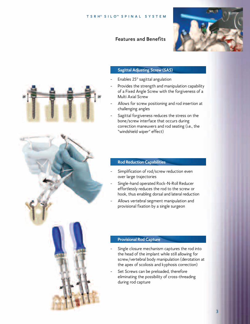


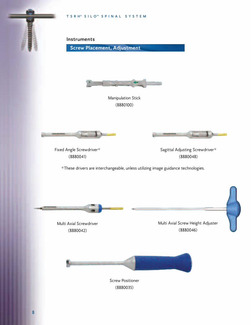


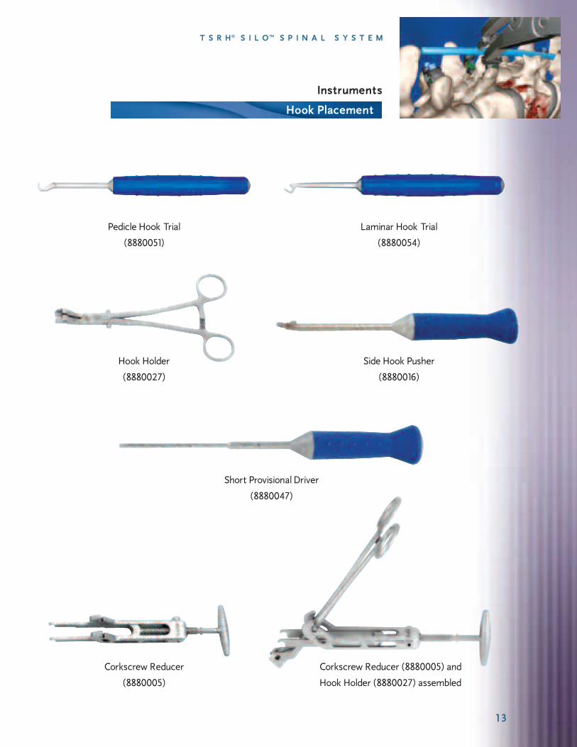


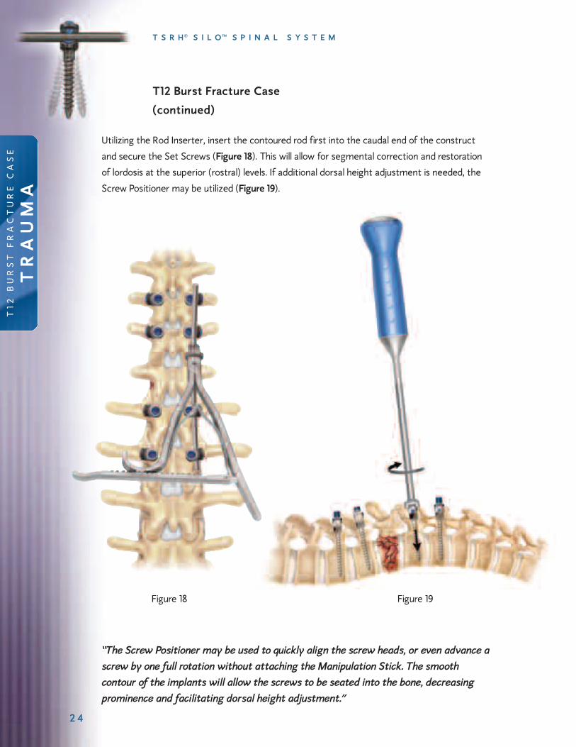


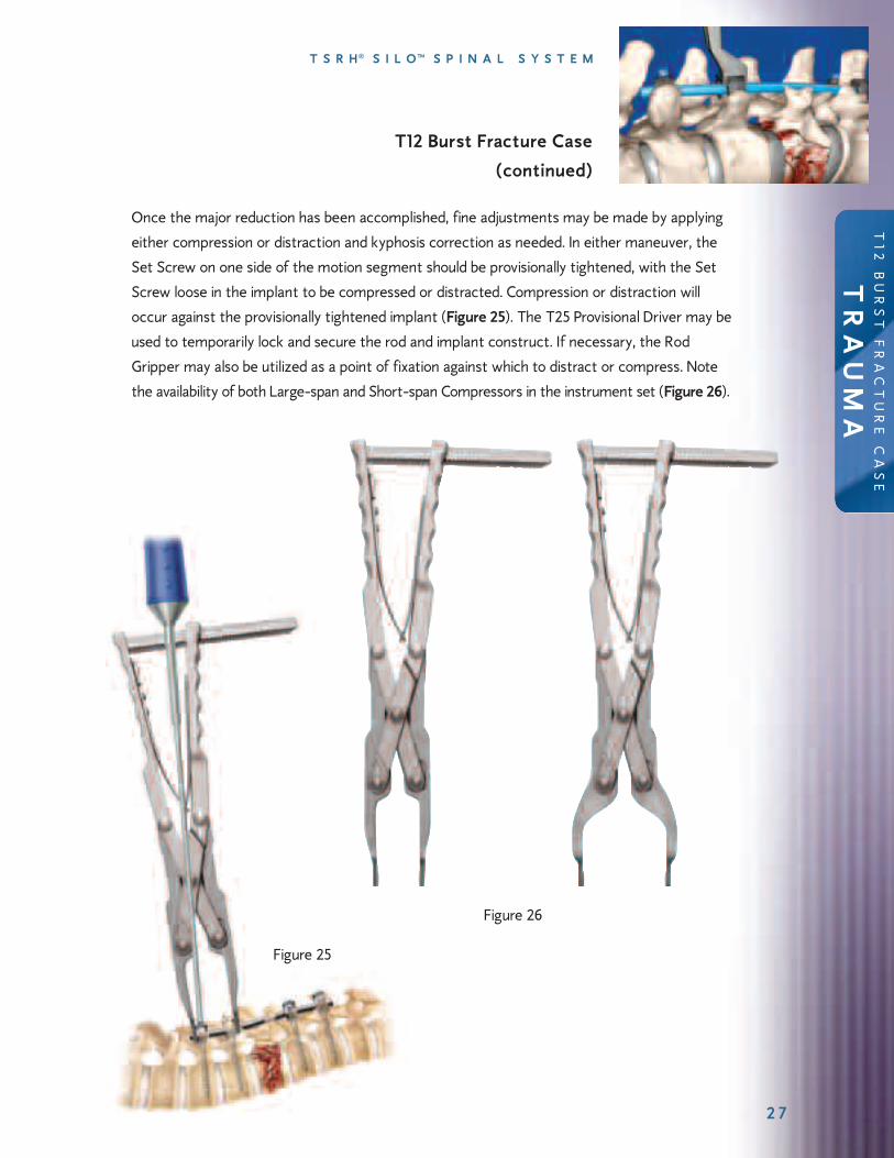


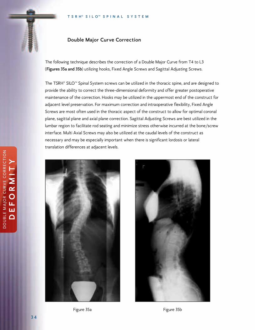


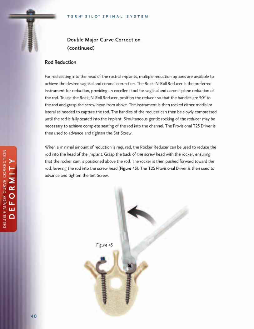


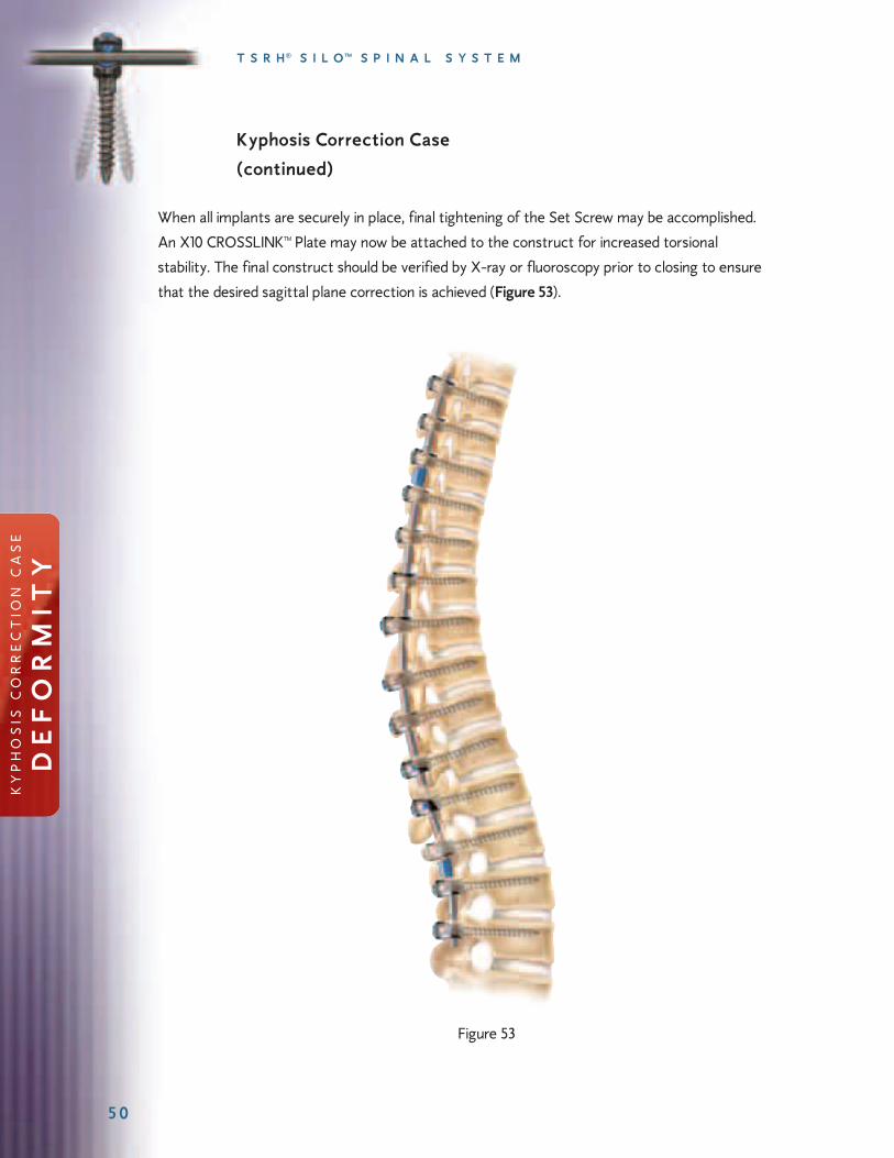

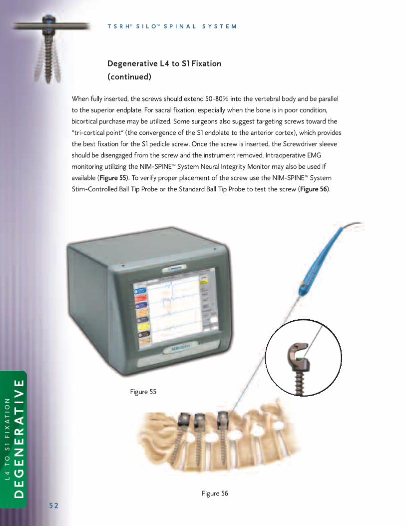


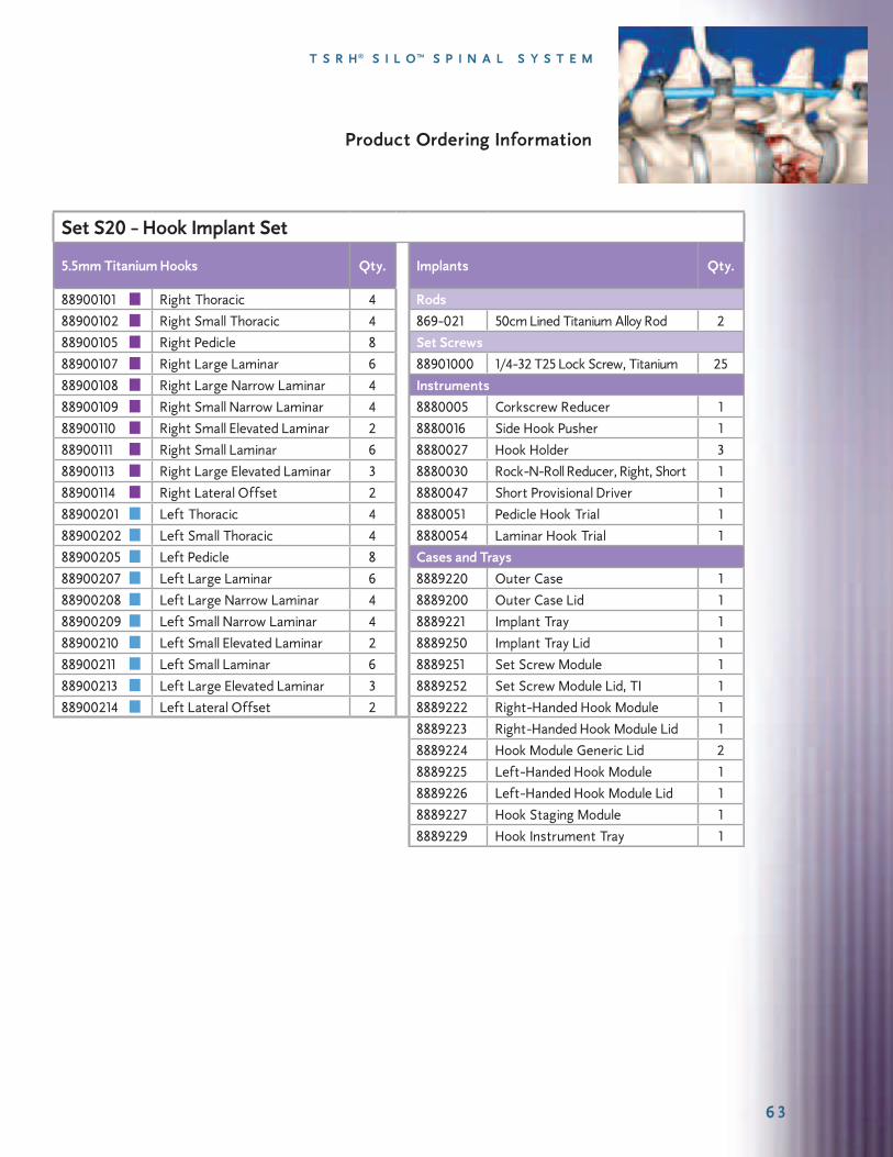


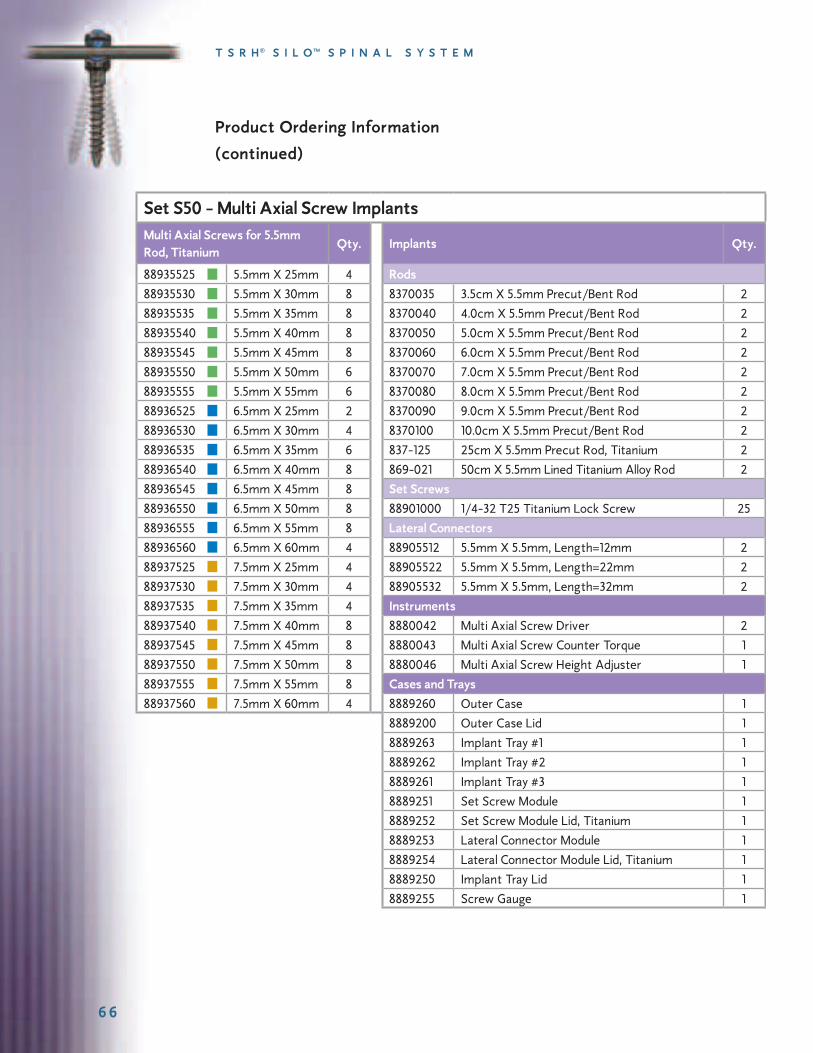


![dpv-uk.com · PDF fileEndure of Thermal shock. ... Ash Silo wz Pneumatic Ash Handling System Layout Chimney Pressue Pump Ash Silo czX-Ð] cz ESP Ash Silo ESP Ash](https://static.documents.pub/doc/80x56/5abd4e267f8b9a7e418b6dff/dpv-ukcom-of-thermal-shock-ash-silo-wz-pneumatic-ash-handling-system-layout.jpg)


