ROADWAY MAINTENANCE AND IMPROVEMENTSWHATCOM COUNTY, WASHINGTON
WHATCOM COUNTYPARKS AND RECREATION
DEPARTMENT
CONSISTING OFBID PROCEDURES AND CONDITIONSSPECIFICATIONS AND CONDITIONS
CONTRACT FORMSPLANS
March 2019
3-11-20192019.03.18 17:47:25 -07'00'
TABLE OF CONTENTS
PART I BID PROCEDURES AND CONDITIONS Invitation to Bid ...................................................................................................... 1
Notice to Bidders ................................................................................................... 2
Supplemental Instructions to Bidders .................................................................... 3
Retainage Bond ................................................................................................. 197
PART IV APPENDICES ....................................................................................... 199 A - Prevailing Wages (State Rates) B - Environmental Permits C - Equipment Rental Agreement D - Geotechnical Report
E - Project Electrical Specifications
PART V PLANS
PART I
BID PROCEDURES AND CONDITIONS
1
INVITATION TO BID NOTICE IS HEREBY GIVEN that sealed bids will be received by Whatcom County Administrative ServicesFinance/Purchasing at their office on the fifth floor of the Whatcom County Courthouse, 311 GrandAvenue Suite 503, BellinghamWA 98225 for the following:
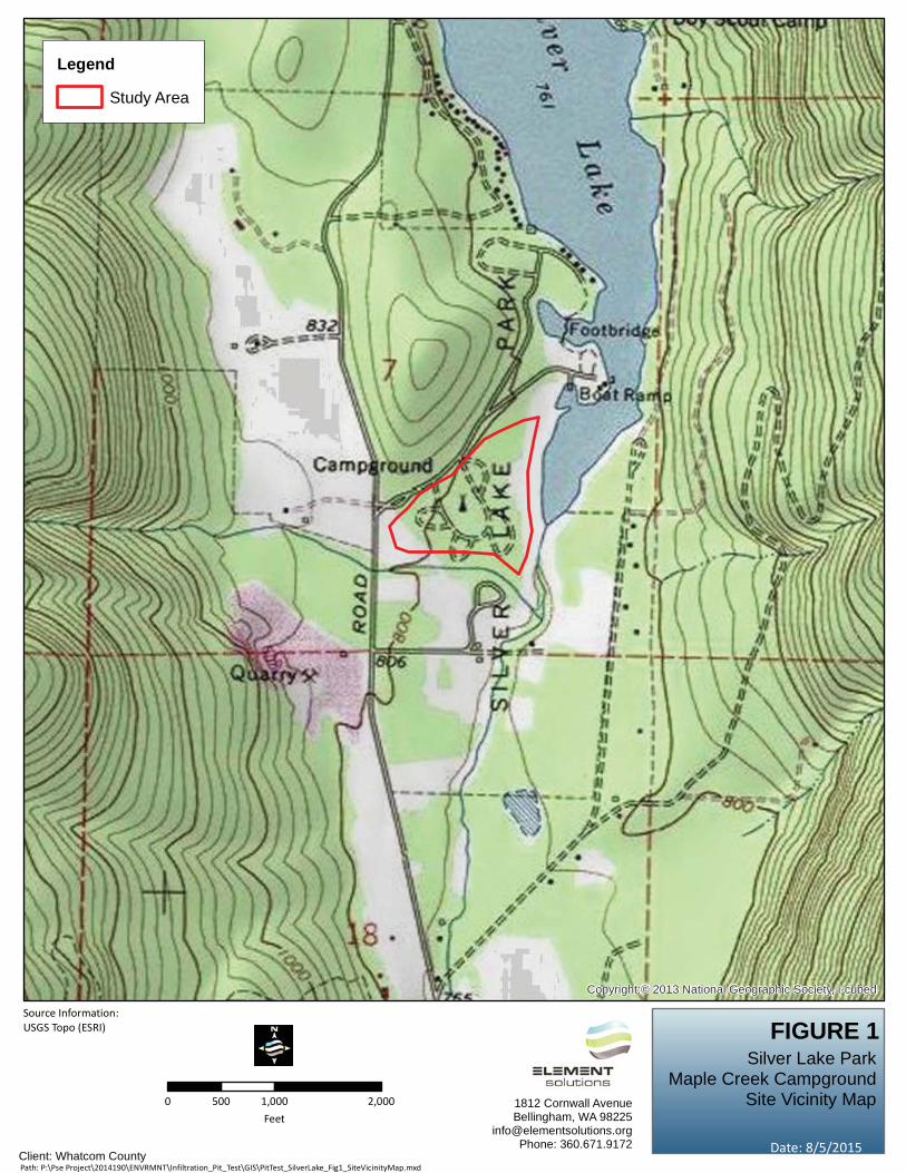
Silver Lake ParkMaple Creek Campground
Roadway Maintenance and ImprovementsUNTIL: 2:30 PM Tuesday, April 2, 2019
At which time and place the bids will be publicly opened and read aloud. All Bidders and any otherinterested people are invited to be present. Late submittals will not be considered.
The Whatcom County Parks Department is requesting bids for the Silver Lake Park Maple CreekCampground Roadway Maintenance and Improvements project. This project includes bituminouspavement construction, excavation, and embankment construction, grading, placement of crushedsurfacing, potable water system improvements, electrical system improvements, and other work asfurther described in the bid documents.
Electronic copies of the bid documents are available at no charge in PDF format; see “Related Documents”at the bottom of this Bid Posting page to download. If you are unable to download the bid documentsfrom this website, contact Purchasing at [email protected] (preferred), or phone (360)778 5330.
Award will be made to the lowest qualified bidder. Whatcom County reserves the right to reject any or allbids, and to waive any irregularities. Whatcom County encourages disadvantaged, minority and womenowned firms to respond.
Whatcom County in accordance with Title VI of the Civil Rights Act of 1964, 78 Stat. 252, 42 U.S.C. 2000dto 2000d 4 and Title 49, Code of Federal Regulations, Department of Transportation, Subtitle A, Office ofthe Secretary, Part 21, Nondiscrimination in Federally Assisted Programs of the Department ofTransportation issued pursuant to such Act, hereby notifies all Bidders that it will affirmatively ensure thatin any contract entered into pursuant to this advertisement, disadvantaged business enterprises asdefined at 49 CFR Part 26 will be afforded full opportunity to submit bids in response to this invitation andwill not be discriminated against on the grounds of race, color, national origin, or sex in consideration foraward. As required by law, the E Verify System may be required.
A pre bid meeting will be held on site at 1:30 PM, Thursday, March 28, 2019, at the entrance to SilverLake Park. Potential bidders are strongly encouraged to attend the pre bid meeting. For specific directionsto the site, call the Whatcom County Parks Department at (360) 778 5850.
Publication Dates: Wednesdays March 20 and 27, 2019.
2
NOTICE TO BIDDERS
Whatcom County, in accordance with Title VI of the Civil Rights Act of 1964, 78 Stat. 252, 42 U.S.C. 2000d to 2000d-4 and Title 49, Code of Federal Regulations, Department of Transportation, Subtitle A, Office of the Secretary, Part 21, nondiscrimination in federally assisted programs of the Department of Transportation issued pursuant to such Act, hereby notifies all bidders that it will affirmatively insure that in any contract entered into pursuant to this advertisement, disadvantaged business enterprises as defined at 49 CFR Part 26 will be afforded full opportunity to submit bids in response to this invitation and will not be discriminated against on the grounds of race, color, national origin, or sex in consideration for an award. As required by law, the E-Verify System may be required.
Copies of plans and specifications are on file in the office of Whatcom County ADS/Purchasing, 311 Grand Avenue, Suite 503, Bellingham, Washington 98225. All bid and project-related questions must be directed in writing to Rod Lamb at [email protected] and carbon copy to Christ Thomsen at [email protected]. Electronic copies of maps, plans and specifications can be Downloaded at no charge on the Whatcom County Purchasing website at http://www.co.whatcom.wa.us/Bids.aspx. Contact [email protected] if you are unable to download the documents. All bid proposals shall be accompanied by a bid proposal deposit in cash, certified check, cashier’s check, or surety bond in an amount equal to five (5) percent of the amount of such bid proposal. Should the successful Bidder fail to enter into such contract and furnish satisfactory performance (contract) bond within the time stated in the specifications, the bid proposal deposit shall be forfeited to Whatcom County. Whatcom County reserves the right to accept a proposal of the bidder submitting the lowest responsible bid, to reject any or all bids, republish the call for bids, revise or cancel the work to be performed, or do the work otherwise, if in the judgment of the County Engineer the best interest of Whatcom County is served thereby. Whatcom County also reserves the right to postpone the bid award for a period of thirty (30) calendar days after bid opening, except that upon mutual consent of the lowest responsible bidder and Whatcom County, the 30-calendar day limit may be extended to allow legislative approval of the bid award.
3
SUPPLEMENTAL INSTRUCTIONS TO BIDDERS
PREPARATION OF PROPOSAL Each bid proposal shall be submitted on the forms included in the “Bid Proposal Forms” section following. All blank spaces on forms shall be completed in ink or be typewritten. Any omission of prices for items included on the Bid Form, or any addition in writing to the form of the bid proposal or any condition, limitation, or provision not officially invited in these contract documents may render the proposal as being incomplete or modified and may become cause for rejection of the bid. All bid prices shall be shown in the designated locations under the corresponding headings on the “Bid” Form. The unit, extended unit, or lump sum price for each bid item shall include, as shown on the “Bid” Form complete under each heading, all costs for labor, materials, tools, equipment, overhead, and profit. No additional compensation for these items shall be allowed, except through an approved change order as provided for in these contract documents.
Bid Additive 1 is a supplemental group of bid items, identified separately in the Bid Proposal, which may, at the discretion of the Contracting Agency, be awarded in addition to the Base Bid. The sum shown for the Base Bid and the Bid Additive 1 amounts shall be the amount for which the Bidder offers to perform and which the bidder agrees to accept for the work described in these documents.
The basis of Award will be based on the sum of the Base Bid and Bid Additive 1 amount, including sales tax. No additional compensation for these items shall be allowed except through an approved change order as provided for in these contract documents. At the option and direction of Whatcom County, work may be added or deleted in accordance with the contract provisions hereunder. No Washington State Sales Tax will be paid by Whatcom County on labor or services on road related items of work. For road related items of work, the bidder shall include within the various bid item prices or other contract amounts any contractor-paid Washington State Retail Sales Tax on materials, equipment, or supplies used or consumed in doing the work. For non-road related items of work, including water and sewer, Washington State Retail Sales Tax will be paid by Whatcom County and the amount of such tax shall be separately stated by the bidder in the space provided on this Bid Proposal form. The Base Bid has been divided into two schedules to separate the work between road-related and non-road related items of work. Base Bid Schedule ‘A’ includes road related work where sales tax will not be paid by Whatcom County as described above. Base Bid Schedule ‘B’ include non-road related work where sales tax will be paid by Whatcom County as described above. Either both schedules will be awarded, or no contract will be awarded at all. Bid Additive 1 is considered non-road related work where sales tax will be paid by Whatcom County as described above.
4
Bidders shall fill in and complete the information requested on the “Bidder Identification” form. Bid proposals shall be signed in full by the person or persons legally authorized to bind the bidder to a contract. A bid by a corporation shall further give the state of incorporation and have the corporate seal affixed. A bid submitted by an agent shall have attached a current power of attorney certifying the agent’s authority to bind the Bidder. The name of each person signing shall be typed or printed below the signature. PRE-BID MEETING
Bidders are aware that a pre-bid meeting will be held at 1:30 p.m., THURSDAY, the 28th
day of March, 2019 at the entrance to Silver Lake Park. Potential bidders are strongly encouraged to attend the pre-bid meeting. For further information, contact the Whatcom County Parks Department at (360) 778-5850.
BID PROPOSAL DEPOSIT As a guarantee of good faith and as required by the law, each bid shall be accompanied by a bid bond in the form of a certified check, bank cashier’s check, or surety bond, in accordance with the provisions of Section 1-02.7 of the Standard Specifications and shall be made payable to Whatcom County. A surety bond shall be submitted on the bid bond form in the Bid Proposal Forms section following. In the event of the withdrawal of this bid proposal after the receipt and opening of bid proposals, or the failure of the Bidder to enter into a contract and give the required contract bond and insurance certification within 20-calendar days after the date of contract award, the Bidder shall be liable to Whatcom County for the amount of five (5) percent of the total amount of the bid as liquidated damages due to the default of the Bidder. SUBMITTAL OF PROPOSAL The completed Bid Proposal Forms and any other documents required in accordance with the Special Provisions shall be submitted to the office of Whatcom County Administrative Services – Purchasing, 311 Grand Avenue, Suite 503, Bellingham, WA 98225 in an opaque envelope marked: Proposal for Contract (Name of Bidder) Project: SILVER LAKE PARK MAPLE CREEK CAMPGROUND ROADWAY MAINTENANCE AND IMPROVEMENTS Whatcom County, Washington
5
Bid proposals shall be deposited at the designated location prior to the date and time for receipt of bid proposals as indicated in the “Invitation to Bid,” or such revised date as may be specified by an addendum. No oral, telephone, or electronically submitted bids or modifications will be considered. INTERPRETATIONS AND CORRECTIONS
If the Bidder finds any discrepancy in, or omission from the specifications or plans, or if there is any doubt as to their meaning, the Bidder shall promptly notify Rod Lamb at [email protected]. Any addenda issued during the time of bidding will be numbered consecutively and will be incorporated into these contract documents. The Bidder shall be responsible to ascertain, prior to submittal of a bid proposal that all addenda issued have been received and are acknowledged on the "Bid Proposal Signature and Addendum Acknowledgment" form. Addendums will only be issued to those contractors appearing on the Plan Holders List at Whatcom County Administrative Services - Purchasing. It will be the responsibility of the contractor to ensure their name appears on the Plan Holders List.
6
BID PROPOSAL FORMS
7
BID PROPOSAL
SILVER LAKE PARK MAPLE CREEK CAMPGROUND
ROADWAY MAINTENANCE AND IMPROVEMENTS
DATE: April 2nd, 2019 TO: Whatcom County Executive and Council Whatcom County Courthouse 311 Grand Avenue Bellingham, Washington 98225 Gentlepersons: This certifies that the Undersigned has examined the location of the project site and the conditions of work; and has carefully read and thoroughly understands the contract documents entitled: “Silver Lake Park Maple Creek Campground Roadway Maintenance and Improvements” Whatcom County, Washington, including the “Bid Procedures and Conditions,” “Specifications and Conditions,” “Contract Forms,” “Appendices” and “Plans,” governing the work embraced in this project, and the method by which payment will be made for said work. The Undersigned hereby proposes to undertake and complete the work embraced in this project in accordance with said contract documents, and agrees to accept as payment for said work, the schedule of lump sum and unit prices as set forth in the “Bid” below. The Undersigned acknowledges that payment will be based on the actual work performed and material used as measured or provided for in accordance with the said contract documents, and that no additional compensation will be allowed for any taxes not included in each lump sum or unit price, and that the basis for payment will be the actual work performed and measured or provided for in accordance with the said contract documents. The Undersigned certifies that it is not currently disqualified from bidding on any public works contract under RCW 39.06.010 or RCW 39.12.065(3).
8
BID ITEM NUMBER DESCRIPTION SPEC QTY UNIT
UNITPRICE IN FIGURES
EXT. PRICE IN FIGURES
BASE BID SCHEDULE 'A' - ROAD WORK (NON-TAXABLE)
1 MOBILIZATION 1-09.7 1 L.S.
2 PROJECT TEMPORARY TRAFFIC CONTROL
1-10 1 L.S.
3SPILL PREVENTION
CONTROL AND COUNTERMEASURES PLAN
1-07.15(1) 1 L.S.
4 CLEARING AND GRUBBING
2-01SP 1 L.S.
5 ADDITIONAL TREE AND STUMP REMOVAL
2-01SP 1 F.A. $10,000 $10,000
6 TREE STUMP REMOVAL AND VOID FILL
2-01SP 1 L.S.
7 CHIP STOCKPILE REMOVAL
2-01SP 500 C.Y.
8 REMOVAL OF STRUCTURE AND OBSTRUCTION
2-02SP 1 L.S.
9 ROADWAY EXCAVATION INCL. HAUL
2-03SP 1 L.S.
10
UNSUITABLE FOUNDATION
EXCAVATION INCLUDING HAUL
2-03SP 500 C.Y.
11 GRAVEL BASE 4-04SP 7,450 TON
12 CRUSHED SURFACING BASE COURSE
4-04SP 7,750 TON
13 CRUSHED LIMESTONE SURFACING, TOP COURSE
4-04SP 250 TON
14 HMA, CLASS 1/2-INCH, PG 64-22
5-04SP 2,150 TON
15 EROSION/WATER POLLUTION CONTROL
8-01SP 1 L.S.
9
BID ITEM NUMBER DESCRIPTION SPEC QTY UNIT
UNITPRICE IN FIGURES
EXT. PRICE IN FIGURES
16 MULCHING 8-01SP 2.00 ACRE
17 TOPSOIL TYPE B 8-02SP 1.30 ACRE
18 PERMANENT SIGNING 8-21SP 1 L.S.
19 PLASTIC ACCESS PARKING SPACE SYMBOL
8-22SP 3 EA.
20 PLASTIC CROSSHATCH MARKING
8-22SP 425 L.F.
21 UNANTICIPATED SITE WORK
1-04.4SP EST DOL $65,000 $65,000
TOTAL OF BASE BID SCHEDULE ‘A’ $
10
BID ITEM NUMBER DESCRIPTION SPEC QTY UNIT
UNITPRICE IN FIGURES
EXT. PRICE IN FIGURES
BASE BID SCHEDULE 'B' - NON-ROAD WORK (TAXABLE)
22 TRASH ENCLOSURE (COMPLETE)
6-02SP 2 EA.
23SOLID WALL PVC
STORM SEWER PIPE, 6-INCH DIAM.
7-04SP 40 L.F.
24PVC PRESSURE PIPE
FOR WATER MAIN 3/4-INCH DIAM.
7-09SP 3,481 L.F.
25PVC PRESSURE PIPE FOR WATER MAIN 1-
INCH DIAM. 7-09SP 344 L.F.
26PVC PRESSURE PIPE FOR WATER MAIN 1-
1/2-INCH DIAM. 7-09SP 768 L.F.
27PVC PRESSURE PIPE FOR WATER MAIN 2-
INCH DIAM. 7-09SP 2,022 L.F.
28PVC PRESSURE PIPE FOR WATER MAIN 4-
INCH DIAM. 7-09SP 1,318 L.F.
29TRENCHING FOR
WATERLINE DISCONNECTION
7-09SP 65 L.F.
30 BLOWOFF ASSEMBLY 7-09SP 8 EA.
31 TESTING WATERMAIN 7-09SP 1 L.S.
32COMB. AIR
RELEASE/AIR VACUUM VALVE ASSEMBLY 2 IN.
7-12SP 5 EA.
33 FROST-FREE HYDRANT ASSEMBLY
7-12SP 50 EA.
34 ELECTRICAL SYSTEM (COMPLETE)
8-30SP 1 L.S.
35 CONCRETEWHEELSTOP
8-30SP 74 EA.
11
BID ITEM NUMBER DESCRIPTION SPEC QTY UNIT
UNITPRICE IN FIGURES
EXT. PRICE IN FIGURES
36 INSTALL FIRE RING 8-30SP 49 EA.
BASE BID SCHEDULE ‘B’ SUBTOTAL $
BASE BID SCHEDULE ‘B’ TAX (8.5% OF BASE BID SCHEDULE ‘B’ SUBTOTAL)
$
TOTAL OF BASE BID SCHEDULE ‘B’ $
TOTAL BASE BID AMOUNT(SCHEDULE ‘A’ + SCHEDULE ‘B’) $
12
BID ITEM NUMBER DESCRIPTION SPEC QTY UNIT
UNITPRICE IN FIGURES
EXT. PRICE IN FIGURES
BID ADDITIVE 1 - NON-ROAD WORK (TAXABLE)
37 MOBILIZATION 1-09.7 1 L.S.
38SOLID WALL PVC
STORM SEWER PIPE, 4-INCH DIAM.
7-04SP 1,060 L.F.
392-INCH PVC
WATERMAIN DRAIN VAULT
7-12SP 4 EA.
404-INCH PVC
WATERMAIN DRAIN VAULT
7-12SP 2 EA.
41 ASSEMBLE PICNIC TABLE
8-30SP 49 EA.
42 VEHICLE ACCESS GATE 8-30SP 10 EA.
BID ADDITIVE 1 SUBTOTAL $
BID ADDITIVE 1 TAX (8.5% OF BID ADDITIVE 1 SUBTOTAL)
$
TOTAL OF BID ADDITIVE 1 $
TOTAL BID AMOUNT (BASE BID + BID ADDITIVE 1) $
13
14
NON-COLLUSION DECLARATION
SILVER LAKE PARK MAPLE CREEK CAMPGROUND ROADWAY MAINTENANCE AND IMPROVEMENTS
I, by signing the proposal, hereby declare, under penalty of perjury under the laws of the United States that the following statements are true and correct: 1. That the undersigned person(s), firm, association, or corporation has (have)
not, either directly or indirectly, entered into any agreement, participated in any collusion, or otherwise taken any action in restraint of free competitive bidding in connection with the project for which this proposal is submitted.
2. That by signing the signature page of this proposal, I am deemed to have
signed and have agreed to the provisions of this declaration. NOTICE TO ALL BIDDERS To report bid rigging activities, call: 1-800-424-9071 The U.S. Department of Transportation (USDOT) operates the above toll free “hotline” Monday through Friday, 8:00 a.m. to 5:00 p.m. Eastern time. Anyone with knowledge of possible bid rigging, bidder collusion, or other fraudulent activities should use the “hotline” to report such activities. The “hotline” is part of USDOT’s continuing effort to identify and investigate highway construction contract fraud and abuse, and is operated under the direction of the USDOT Inspector General. All information will be treated confidentially and caller anonymity will be respected.
15
BIDDER IDENTIFICATION
The name of the Bidder submitting this proposal, the address and phone number to which all communications concerned with this proposal shall be made, and the number which has been assigned indicating the Bidder is licensed to do business in the State of Washington are as follows: Firm Name: Address: Telephone: Contractor’s WA Registration Number: Contractor’s WA UBI Number: Contractor’s WA Employment Security Department Number: Contractor’s WA Excite Tax Registration Number: The firm submitting this proposal is a: Sole Proprietorship Partnership Corporation The names and titles of the principal officers of the corporation submitting this proposal, or of the partnership, or of all persons interested in this proposal as principals are as follows: NOTE: Signatures of this Bid must be identified above. Failure to identify the
Signatories will be cause for considering the proposal irregular and for subsequent rejection of the Bid.
16
BID PROPOSAL SIGNATURE AND ADDENDUM ACKNOWLEDGEMENT
The bidder is hereby advised that by signature of this proposal he/she is deemed to have acknowledged all requirements and signed all certificates contained herein. The undersigned hereby agrees to pay labor not less than the prevailing rates of wages or less than the hourly minimum rate of wages as specified in the Specifications and Conditions for this project.
CASH IN THE AMOUNT OF $
CASHIER’S CHECK ($____________ dollars)
CERTIFIED CHECK ($____________ dollars) PAYABLE TO WHATCOM COUNTY
PROPOSAL BOND IN THE AMOUNT OF 5% OF THE BID Receipt is hereby acknowledged by Addendum(s) No.(s) _______, _______, & ______
SIGNATURE OF AUTHORIZED OFFICIAL(S)
(PROPOSAL MUST BE SIGNED) _____________________________________ (Seal) FIRM NAME: STATE OF WASHINGTON ) ) ss. COUNTY OF ) On this ______ day of __________________, 20__, before me personally appeared ________________________________ to me personally known to be the person described in and who executed the above instrument and who acknowledged to me the act of signing thereof. _____________ NOTARY PUBLIC, in and for the __________________ State of Washington, residing at: __________________ My Commission Expires: ________________________ This proposal form is not transferable and any alteration of the firm’s name entered hereon without prior permission from Whatcom County will be cause for considering the proposal irregular and for subsequent rejection of the bid.
17
BID BOND
KNOW ALL MEN BY THESE PRESENTS, that we, ____________________________ of ______________________________________, as principal, and the ____________ a corporation duly organized under the laws of the State of _______________________ and having its principal place of business at __________________________________ in the State of Washington, as Surety, are held and firmly bound unto Whatcom County, a Municipal Corporation in the State of Washington, in the full and penal sum of five percent (5%) of the total bid amount appearing on the bid proposal of said principal for the work hereinafter described, for the payment of which, well, and truly to be made, we bind our heirs, executors, administrators and assigns, and successors and assigns, jointly and severally, firmly by these presents. The condition of this bond is such that, whereas, the principal herein is herewith submitting his or its bid proposal for Silver Lake Park Maple Creek Campground Roadway Maintenance and Improvements bid proposal, by reference thereto, being hereby made a part thereof. NOW, THEREFORE, if the said bid proposal submitted by the said PRINCIPAL be accepted, and the contract be awarded to said PRINCIPAL, and if said PRINCIPAL shall duly make and enter into and execute said contract and shall furnish the performance bond as required by the bidding and contract documents within a period of ten (10) days from and after said ward, exclusive of the day of such award, the its obligation to pay the above-mentioned penal sum as liquidated damages shall be null and void, otherwise it shall remain and be in full force and effect. SIGNED AND SEALED this ______ day of _____________________, 20___. Principal By (Seal) Surety By Attorney-in-Fact The Attorney-in-fact who executes this bond on behalf of the surety company, must attach a copy of his power-of-attorney as evidence of his authority.
18
Certification of Compliance with Wage Payment Statutes(Original signed form must be submitted prior to contract award.)
The bidder hereby certifies that, within the three year period immediately preceding the bidsolicitation date March 20, 2019, the bidder is not a “willful” violator, as defined in RCW49.48.082, of any provision of chapters 49.46, 49.48, or 49.52 RCW, as determined by a final andbinding citation and notice of assessment issued by the Department of Labor and Industries orthrough a civil judgment entered by a court of limited or general jurisdiction.
I certify under penalty of perjury under the laws of the State of Washington that the foregoing istrue and correct.
State of Incorporation, or if not a corporation, State where business entity was formed:
If a co partnership, give firm name under which business is transacted:
* If a corporation, proposal must be executed in the corporate name by the president or vice president (orany other corporate officer accompanied by evidence of authority to sign). If a co partnership, proposalmust be executed by a partner.
19
20
PART II
SPECIFICATIONS AND CONDITIONS
21
INTRO.AP1 1 INTRODUCTION2
The following Amendments and Special Provisions shall be used in conjunction with the 2018 3 Standard Specifications for Road, Bridge, and Municipal Construction. 4 5
AMENDMENTS TO THE STANDARD SPECIFICATIONS 6 7 The following Amendments to the Standard Specifications are made a part of this contract and 8 supersede any conflicting provisions of the Standard Specifications. For informational 9 purposes, the date following each Amendment title indicates the implementation date of the 10 Amendment or the latest date of revision. 11 12 Each Amendment contains all current revisions to the applicable section of the Standard 13 Specifications and may include references which do not apply to this particular project. 14 15 1-01.AP1 16 Section 1-01, Definitions and Terms 17 August 6, 2018 18
1-01.3 Definitions 19 The following new term and definition is inserted before the definition for “Shoulder”: 20 21
Sensitive Area – Natural features, which may be previously altered by human activity, that 22 are present on or adjacent to the project location and protected, managed, or regulated by 23 local, tribal, state, or federal agencies. 24
25 The following new term and definition is inserted after the definition for “Working Drawings”: 26 27
WSDOT Form – Forms developed and maintained by WSDOT that are required or 28 available for use on a project. These forms can be downloaded from the forms catalogue 29 at: 30 31
http://wsdot.wa.gov/forms/pdfForms.html 32 33 1-02.AP1 34 Section 1-02, Bid Procedures and Conditions 35 October 30, 2018 36
1-02.4(1) General 37 This section is supplemented with the following: 38 39
Prospective Bidders are advised that the Contracting Agency may include a partially 40 completed Washington State Department of Ecology (Ecology) Transfer of Coverage 41 (Ecology Form ECY 020-87a) for the Construction Stormwater General Permit (CSWGP) 42 as part of the Bid Documents. When the Contracting Agency requires the transfer of 43 coverage of the CSWGP to the Contractor, an informational copy of the Transfer of 44 Coverage and the associated CSWGP will be included in the appendices. As a condition of 45 Section 1-03.3, the Contractor is required to complete sections I, III, and VIII of the Transfer 46 of Coverage and return the form to the Contracting Agency. 47
22
1 The Contracting Agency is responsible for compliance with the CSWGP until the end of day 2 that the Contract is executed. Beginning on the day after the Contract is executed, the 3 Contractor shall assume complete legal responsibility for compliance with the CSWGP and 4 full implementation of all conditions of the CSWGP as they apply to the Contract Work. 5
6 1-02.5 Proposal Forms 7 The first sentence of the first paragraph is revised to read: 8 9
At the request of a Bidder, the Contracting Agency will provide a physical Proposal Form 10 for any project on which the Bidder is eligible to Bid. 11
12 1-02.6 Preparation of Proposal 13 Item number 1 of the second paragraph is revised to read: 14 15
1. A unit price for each item (omitting digits more than two places to the right of the 16 decimal point), 17
18 In the third sentence of the fourth paragraph, “WSDOT Form 422-031” is revised to read 19 “WSDOT Form 422-031U”. 20 21 The following new paragraph is inserted before the last paragraph: 22 23
The Bidder shall submit with their Bid a completed Contractor Certification Wage Law 24 Compliance form (WSDOT Form 272-009). Failure to return this certification as part of the 25 Bid Proposal package will make this Bid Nonresponsive and ineligible for Award. A 26 Contractor Certification of Wage Law Compliance form is included in the Proposal Forms. 27 28
29 1-03.AP1 30 Section 1-03, Award and Execution of Contract 31 January 2, 2018 32
1-03.3 Execution of Contract 33 The first paragraph is revised to read: 34 35
Within 20 calendar days after the Award date, the successful Bidder shall return the signed 36 Contracting Agency-prepared Contract, an insurance certification as required by Section 1-37 07.18, a satisfactory bond as required by law and Section 1-03.4, the Transfer of Coverage 38 form for the Construction Stormwater General Permit with sections I, III, and VIII completed 39 when provided, and shall be registered as a contractor in the state of Washington. 40 41
1-03.5 Failure to Execute Contract 42 The first sentence is revised to read: 43 44
Failure to return the insurance certification and bond with the signed Contract as required in 45 Section 1-03.3, or failure to provide Disadvantaged, Minority or Women’s Business 46 Enterprise information if required in the Contract, or failure or refusal to sign the Contract, 47 or failure to register as a contractor in the state of Washington, or failure to return the 48
23
completed Transfer of Coverage for the Construction Stormwater General Permit to the 1 Contracting Agency when provided shall result in forfeiture of the proposal bond or deposit 2 of this Bidder. 3
4 1-05.AP1 5 Section 1-05, Control of Work 6 August 6, 2018 7
1-05.5 Vacant 8 This section, including title, is revised to read: 9 10
1-05.5 Tolerances11 Geometrical tolerances shall be measured from the points, lines, and surfaces defined in 12 Contract documents. 13 14 A plus (+) tolerance increases the amount or dimension to which it applies, or raises a 15 deviation from level. A minus (-) tolerance decreases the amount or dimension to which it 16 applies, or lowers a deviation from level. Where only one signed tolerance is specified (+ or 17 -), there is no specified tolerance in the opposing direction. 18 19 Tolerances shall not be cumulative. The most restrictive tolerance shall control. 20 21 Tolerances shall not extend the Work beyond the Right of Way or other legal boundaries 22 identified in the Contract documents. If application of tolerances causes the extension of 23 the Work beyond the Right of Way or legal boundaries, the tolerance shall be reduced for 24 that specific instance. 25 26 Tolerances shall not violate other Contract requirements. If application of tolerances causes 27 the Work to violate other Contract requirements, the tolerance shall be reduced for that 28 specific instance. If application of tolerances causes conflicts with other components or 29 aspects of the Work, the tolerance shall be reduced for that specific instance. 30
31 1-05.9 Equipment 32 The following new paragraph is inserted before the first paragraph: 33 34
Prior to mobilizing equipment on site, the Contractor shall thoroughly remove all loose dirt 35 and vegetative debris from drive mechanisms, wheels, tires, tracks, buckets and 36 undercarriage. The Engineer will reject equipment from the site until it returns clean. 37 38
This section is supplemented with the following: 39 40
Upon completion of the Work, the Contractor shall completely remove all loose dirt and 41 vegetative debris from equipment before removing it from the job site. 42
43
24
1-06.AP1 1 Section 1-06, Control of Material 2 January 7, 2019 3
1-06.1(3) Aggregate Source Approval (ASA) Database 4 This section is supplemented with the following: 5 6
Regardless of status of the source, whether listed or not listed in the ASA database the 7 source owner may be asked to provide testing results for toxicity in accordance with 8 Section 9-03.21(1). 9
10 1-06.2(2)D Quality Level Analysis 11 This section is supplemented with the following new subsection: 12 13
1-06.2(2)D5 Quality Level Calculation – HMA Compaction14 The procedures for determining the quality level and pay factor for HMA compaction are as 15 follows: 16 17
1. Determine the arithmetic mean, Xm, for compaction of the lot: 18 19
nxX m 20
21 Where: 22 x = individual compaction test values for each sublot in the lot. 23
x = summation of individual compaction test values 24 n = total number test values 25
26 2. Compute the sample standard deviation, “S”, for each constituent: 27 28
21
22
1nnxxn
S 29
30 Where: 31
x2 = summation of the squares of individual compaction test values 32 ( x)2 = summation of the individual compaction test values squared 33 34
3. Compute the lower quality index (QL): 35 36
SLSLXQ m
L 37
38 Where: 39 LSL = 92.0 40
41 4. Determine PL (the percent within the lower Specification limit which corresponds to 42
a given QL) from Table 1. For negative values of QL, PL is equal to 100 minus the 43
25
table PL. If the value of QL does not correspond exactly to a figure in the table, use 1 the next higher value. 2
3 5. Determine the quality level (the total percent within Specification limits): 4 5
Quality Level = PL 6 7 6. Using the quality level from step 5, determine the composite pay factor (CPF) from 8
Table 2. 9 10 7. If the CPF determined from step 6 is 1.00 or greater: use that CPF for the 11
compaction lot; however, the maximum HMA compaction CPF using an LSL = 12 92.0 shall be 1.05. 13
14 8. If the CPF from step 6 is not 1.00 or greater: repeat steps 3 through 6 using an 15
LSL = 91.5. The value thus determined shall be the HMA compaction CPF for that 16 lot; however, the maximum HMA compaction CPF using an LSL = 91.5 shall be 17 1.00. 18
19 1-06.2(2)D1 Quality Level Analysis 20 The following new sentence is inserted after the first sentence: 21 22
The quality level calculations for HMA compaction are completed using the formulas in 23 Section 1-06.2(2)D5. 24
25 1-06.2(2)D4 Quality Level Calculation 26 The first paragraph (excluding the numbered list) is revised to read: 27 28
The procedures for determining the quality level and pay factors for a material, other than 29 HMA compaction, are as follows: 30
31 1-06.6 Recycled Materials 32 The first three sentences of the second paragraph are revised to read: 33 34
The Contractor shall submit a Recycled Material Utilization Plan on WSDOT Form 350-35 075A within 30 calendar days after the Contract is executed. The plan shall provide the 36 Contractor’s anticipated usage of recycled concrete aggregates for meeting the 37 requirements of these Specifications. The quantity of recycled concrete aggregate will be 38 provided in tons and as a percentage of the Plan quantity for eligible material listed in 39 Section 9-03.21(1)E Table on Maximum Allowable percent (By Weight) of Recycled 40 Material. 41
42 The last paragraph is revised to read: 43 44
Within 30 calendar days after Physical Completion, the Contractor shall report the quantity 45 of recycled concrete aggregates that were utilized in the construction of the project for each 46 eligible item listed in Section 9-03.21(1)E. The Contractor’s report shall be provided on 47 WSDOT Form 350-075A, Recycled Materials Reporting. 48
49
26
1-06.6(1)A General 1 Item 1(a) in the second paragraph is revised to read: 2 3
a. The estimated costs for the Work for each material with 25 percent recycled concrete 4 aggregate. The cost estimate shall include for each material a documented price quote 5 from the supplier with the lowest total cost for the Work. 6
7 1-07.AP1 8 Section 1-07, Legal Relations and Responsibilities to the Public 9 August 6, 2018 10
1-07.5 Environmental Regulations 11 This section is supplemented with the following new subsections: 12 13
1-07.5(5) U.S. Army Corps of Engineers14 When temporary fills are permitted, the Contractor shall remove fills in their entirety and the 15 affected areas returned to pre-construction elevations. 16 17 If a U.S. Army Corps of Engineers permit is noted in Section 1-07.6 of the Special 18 Provisions, the Contractor shall retain a copy of the permit or the verification letter (in the 19 case of a Nationwide Permit) on the worksite for the life of the Contract. The Contractor 20 shall provide copies of the permit or verification letter to all subcontractors involved with the 21 authorized work prior to their commencement of any work in waters of the U.S. 22 23 1-07.5(6) U.S. Fish/Wildlife Services and National Marine Fisheries Service 24 The Contracting Agency will provide fish exclusion and handling services if the Work 25 dictates. However, if the Contractor discovers any fish stranded by the project and a 26 Contracting Agency biologist is not available, they shall immediately release the fish into a 27 flowing stream or open water. 28
29 1-07.5(1) General 30 The first sentence is deleted and replaced with the following: 31 32
No Work shall occur within areas under the jurisdiction of resource agencies unless 33 authorized in the Contract. 34
35 The third paragraph is deleted. 36 37 1-07.5(2) State Department of Fish and Wildlife 38 This section is revised to read: 39 40
In doing the Work, the Contractor shall: 41 42
1. Not degrade water in a way that would harm fish, wildlife, or their habitat. 43 44 2. Not place materials below or remove them from the ordinary high water line 45
except as may be specified in the Contract. 46 47
27
3. Not allow equipment to enter waters of the State except as specified in the 1 Contract. 2
3 4. Revegetate in accordance with the Plans, unless the Special Provisions permit 4
otherwise. 5 6 5. Prevent any fish-threatening silt buildup on the bed or bottom of any body of 7
water. 8 9 6. Ensure continuous stream flow downstream of the Work area. 10 11 7. Dispose of any project debris by removal, burning, or placement above high-water 12
flows. 13 14 8. Immediately notify the Engineer and stop all work causing impacts, if at any time, 15
as a result of project activities, fish are observed in distress or a fish kill occurs. 16 17 If the Work in (1) through (3) above differs little from what the Contract requires, the 18 Contracting Agency will measure and pay for it at unit Contract prices. But if Contract items 19 do not cover those areas, the Contracting Agency will pay pursuant to Section 1-09.4. Work 20 in (4) through (8) above shall be incidental to Contract pay items. 21
22 1-07.5(3) State Department of Ecology 23 This section is revised to read: 24 25
In doing the Work, the Contractor shall: 26 27
1. Comply with Washington State Water Quality Standards. 28 29 2. Perform Work in such a manner that all materials and substances not specifically 30
identified in the Contract documents to be placed in the water do not enter waters 31 of the State, including wetlands. These include, but are not limited to, petroleum 32 products, hydraulic fluid, fresh concrete, concrete wastewater, process 33 wastewater, slurry materials and waste from shaft drilling, sediments, sediment-34 laden water, chemicals, paint, solvents, or other toxic or deleterious materials. 35
36 3. Use equipment that is free of external petroleum-based products. 37 38 4. Remove accumulations of soil and debris from drive mechanisms (wheels, tracks, 39
tires) and undercarriage of equipment prior to using equipment below the ordinary 40 high water line. 41
42 5. Clean loose dirt and debris from all materials placed below the ordinary high water 43
line. No materials shall be placed below the ordinary high water line without the 44 Engineer’s concurrence. 45
46 6. When a violation of the Construction Stormwater General Permit (CSWGP) 47
occurs, immediately notify the Engineer and fill out WSDOT Form 422-011, 48 Contractor ECAP Report, and submit the form to the Engineer within 48 hours of 49 the violation. 50
28
1 7. Once Physical Completion has been given, prepare a Notice of Termination 2
(Ecology Form ECY 020-87) and submit the Notice of Termination electronically to 3 the Engineer in a PDF format a minimum of 7 calendar days prior to submitting 4 the Notice of Termination to Ecology. 5
6 8. Transfer the CSWGP coverage to the Contracting Agency when Physical 7
Completion has been given and the Engineer has determined that the project site 8 is not stabilized from erosion. 9
10 9. Submit copies of all correspondence with Ecology electronically to the Engineer in 11
a PDF format within four calendar days. 12 13 1-07.5(4) Air Quality 14 This section is revised to read: 15 16
The Contractor shall comply with all regional clean air authority and/or State Department of 17 Ecology rules and regulations. 18 19 The air quality permit process may include additional State Environment Policy Act (SEPA) 20 requirements. Contractors shall contact the appropriate regional air pollution control 21 authority well in advance of beginning Work. 22 23 When the Work includes demolition or renovation of any existing facility or structure that 24 contains Asbestos Containing Material (ACM) and/or Presumed Asbestos-Containing 25 Material (PACM), the Contractor shall comply with the National Emission Standards for 26 Hazardous Air Pollutants (NESHAP). 27 28 Any requirements included in Federal and State regulations regarding air quality that 29 applies to the “owner or operator” shall be the responsibility of the Contractor. 30
31 1-07.7(1) General 32 The first sentence of the third paragraph is revised to read: 33 34
When the Contractor moves equipment or materials on or over Structures, culverts or 35 pipes, the Contractor may operate equipment with only the load-limit restrictions in Section 36 1-07.7(2). 37
38 The first sentence of the last paragraph is revised to read: 39 40
Unit prices shall cover all costs for operating over Structures, culverts and pipes. 41 42 1-07.9(1) General 43 The last sentence of the sixth paragraph is revised to read: 44 45
Generally, the Contractor initiates the request by preparing standard form 1444 Request for 46 Authorization of Additional Classification and Rate, available at 47 https://www.dol.gov/whd/recovery/dbsurvey/conformance.htm, and submitting it to the 48 Engineer for further action. 49
50
29
1-07.9(2) Posting Notices 1 The second sentence of the first paragraph (up until the colon) is revised to read: 2 3
The Contractor shall ensure the most current edition of the following are posted: 4 5 In items 1 through 10, the revision dates are deleted. 6 7 1-07.11(2) Contractual Requirements 8 In this section, “creed” is revised to read “religion”. 9 10 Item numbers 1 through 9 are revised to read 2 through 10, respectively. 11 12 After the preceding Amendment is applied, the following new item number 1 is inserted: 13 14
1. The Contractor shall maintain a Work site that is free of harassment, humiliation, fear, 15 hostility and intimidation at all times. Behaviors that violate this requirement include but 16 are not limited to: 17
18 a. Persistent conduct that is offensive and unwelcome. 19 20 b. Conduct that is considered to be hazing. 21 22 c. Jokes about race, gender, or sexuality that are offensive. 23 24 d. Unwelcome, unwanted, rude or offensive conduct or advances of a sexual nature 25
which interferes with a person’s ability to perform their job or creates an 26 intimidating, hostile, or offensive work environment. 27
28 e. Language or conduct that is offensive, threatening, intimidating or hostile based 29
on race, gender, or sexual orientation. 30 31 f. Repeating rumors about individuals in the Work Site that are considered to be 32
harassing or harmful to the individual’s reputation. 33 34 1-07.11(5) Sanctions 35 This section is supplemented with the following: 36 37
Immediately upon the Engineer’s request, the Contractor shall remove from the Work site 38 any employee engaging in behaviors that promote harassment, humiliation, fear or 39 intimidation including but not limited to those described in these specifications. 40
41 1-07.11(6) Incorporation of Provisions 42 The first sentence is revised to read: 43 44
The Contractor shall include the provisions of Section 1-07.11(2) Contractual Requirements 45 (1) through (5) and the Section 1-07.11(5) Sanctions in every subcontract including 46 procurement of materials and leases of equipment. 47
48
30
1-07.15(1) Spill Prevention, Control, and Countermeasures Plan 1 The last sentence of the first paragraph is revised to read: 2 3
An SPCC Plan template and guidance information is available at 4 http://www.wsdot.wa.gov/environment/technical/disciplines/hazardous-materials/spill-5 prevent-report. 6
7 1-07.18 Public Liability and Property Damage Insurance 8 Item number 1 is supplemented with the following new sentence: 9 10
This policy shall be kept in force from the execution date of the Contract until the Physical 11 Completion Date. 12
1-08.1 Subcontracting 16 The first sentence of the seventh paragraph is revised to read: 17 18
All Work that is not performed by the Contractor will be considered as subcontracting 19 except: (1) purchase of sand, gravel, crushed stone, crushed slag, batched concrete 20 aggregates, ready-mix concrete, off-site fabricated structural steel, other off-site fabricated 21 items, and any other materials supplied by established and recognized commercial plants; 22 or (2) delivery of these materials to the Work site in vehicles owned or operated by such 23 plants or by recognized independent or commercial hauling companies hired by those 24 commercial plants. 25
26 The following new paragraph is inserted after the seventh paragraph: 27 28
The Contractor shall not use businesses (material suppliers, vendors, subcontractors, etc.) 29 with federal purchasing exclusions. Businesses with exclusions are identified using the 30 System for Award Management web page at www.SAM.gov. 31
32 1-08.5 Time for Completion 33 Item number 2 of the sixth paragraph is supplemented with the following: 34 35
f. A copy of the Notice of Termination sent to the Washington State Department of 36 Ecology (Ecology); the elapse of 30 calendar days from the date of receipt of the 37 Notice of Termination by Ecology; and no rejection of the Notice of Termination by 38 Ecology. This requirement will not apply if the Construction Stormwater General 39 Permit is transferred back to the Contracting Agency in accordance with Section 8-40 01.3(16). 41
42 1-08.7 Maintenance During Suspension 43 The fifth paragraph is revised to read: 44 45
The Contractor shall protect and maintain all other Work in areas not used by traffic. All 46 costs associated with protecting and maintaining such Work shall be the responsibility of 47 the Contractor. 48
31
1 1-09.AP1 2 Section 1-09, Measurement and Payment 3 August 6, 2018 4
1-09.2(1) General Requirements for Weighing Equipment 5 The last paragraph is supplemented with the following: 6 7
When requested by the Engineer, the Contractor’s representative shall collect the tickets 8 throughout the day and provide them to the Engineer’s designated receiver, not later than 9 the end of shift, for reconciliation. Tickets for loads not verified as delivered will receive no 10 pay. 11
12 1-09.2(2) Specific Requirements for Batching Scales 13 The last sentence of the first paragraph is revised to read: 14 15
Batching scales used for concrete or hot mix asphalt shall not be used for batching 16 other materials. 17
18 1-09.10 Payment for Surplus Processed Materials 19 The following sentence is inserted after the first sentence of the second paragraph: 20 21
For Hot Mix Asphalt, the Plan quantity and quantity used will be adjusted for the quantity of 22 Asphalt and quantity of RAP or other materials incorporated into the mix. 23
24 2-02.AP2 25 Section 2-02, Removal of Structures and Obstructions 26 April 2, 2018 27
2-02.3(3) Removal of Pavement, Sidewalks, Curbs, and Gutters 28 In item number 3 of the first paragraph, the second sentence is revised to read: 29 30
For concrete pavement removal, a second vertical full depth relief saw cut offset 12 to 18 31 inches from and parallel to the initial saw cut is also required, unless the Engineer allows 32 otherwise. 33
2-09.2 Materials 38 In the first paragraph, the references to “Portland Cement” and “Aggregates for Portland 39 Cement Concrete” are revised to read: 40 41
Cement 9-01 42 Fine Aggregate for Concrete 9-03.1(2) 43
44 2-09.3(3)D Shoring and Cofferdams 45 The first sentence of the sixth paragraph is revised to read: 46
32
1 Structural shoring and cofferdams shall be designed for conditions stated in this Section 2 using methods shown in Division I Section 5 of the AASHTO Standard Specifications for 3 Highway Bridges Seventeenth Edition – 2002 for allowable stress design, or the AASHTO 4 LRFD Bridge Design Specifications for load and resistance factor design. 5
6 3-01.AP3 7 Section 3-01, Production from Quarry and Pit Sites 8 April 2, 2018 9
3-01.1 Description 10 The first paragraph is revised to read: 11 12
This Work shall consist of manufacturing and producing crushed and screened aggregates 13 including pit run aggregates of the kind, quality, and grading specified for use in the 14 construction of concrete, hot mix asphalt, crushed surfacing, maintenance rock, ballast, 15 gravel base, gravel backfill, gravel borrow, riprap, and bituminous surface treatments of all 16 descriptions. 17
18 4-04.AP4 19 Section 4-04, Ballast and Crushed Surfacing 20 April 2, 2018 21
4-04.3(5) Shaping and Compaction 22 This section is supplemented with the following new paragraph: 23 24
When using 100% Recycled Concrete Aggregate, the Contractor may submit a written 25 request to use a test point evaluation for compaction acceptance testing in lieu of 26 compacting to 95% of the standard density as determined by the requirements of Section 27 2-03.3(14)D. The test point evaluation shall be performed in accordance with SOP 738. 28
5-01.2 Materials 33 The reference for Concrete Patching Material is revised to read: 34 35
Concrete Patching Material, Grout, and Mortar 9-20.1 36 37 5-01.3(1)A1 Concrete Patching Materials 38 In this section, each reference to “9-20” is revised to read “9-20.1”. 39 40 5-01.3(4) Replace Cement Concrete Panel 41 This section’s content is deleted and replaced with the following new subsections: 42 43
5-01.3(4)A General44 Curing, cold weather work, concrete pavement construction in adjacent lines, and 45 protection of pavement shall meet the requirements of Section 5-05.3(13) through Section 46
33
5-05.3(15). The Contractor, at no cost to the Contracting Agency, shall repair any damage 1 to existing pavement caused by the Contractor’s operations. 2 3 5-01.3(4)B Sawing and Dimensional Requirements4 Concrete slabs to be replaced as shown in the Plans or staked by the Engineer shall be at 5 least 6.0 feet long and full width of an existing pavement panel. The portion of the panel to 6 remain in place shall have a minimum dimension of 6 feet in length and full panel width; 7 otherwise the entire panel shall be removed and replaced. There shall be no new joints 8 closer than 3.0 feet to an existing transverse joint or crack. A vertical full depth saw cut is 9 required along all longitudinal joints and at transverse locations and, unless the Engineer 10 allows otherwise, an additional vertical full depth relief saw cut located 12 to 18 inches from 11 and parallel to the initial longitudinal and transverse saw cut locations is also required. 12 Removal of existing cement concrete pavement shall not cause damage to adjacent slabs 13 that are to remain in place. In areas that will be ground, slab replacements shall be 14 performed prior to pavement grinding. 15 16 Side forms shall meet the requirements of Section 5-05.3(7)B whenever a sawed full depth 17 vertical face cannot be maintained. 18 19 5-01.3(4)C Dowel Bars and Tie Bars20 For the half of a dowel bar or tie bar placed in fresh concrete, comply with the requirements 21 of Section 5-05. 22 23 For the half of a dowel bar or tie bar placed in hardened concrete, comply with the 24 Standard Plans and the following. 25 26 After drilling, secure dowel bars and tie bars into the existing pavement with either an 27 epoxy bonding agent Type I or IV as specified in Section 9-26.1, or a grout Type 2 for non-28 shrink applications as specified in Section 9-20.3. 29 30 Dowel bars shall be placed at the mid depth of the concrete slab, centered over the 31 transverse joint, and parallel to the centerline and to the roadway surface, within the 32 tolerances in the table below. Dowel bars may be adjusted to avoid contact with existing 33 dowel bars in the transverse joint at bridge approach slabs or existing panels provided the 34 adjusted dowel bars meet the tolerances below. 35 36 Tie bars shall be placed at the mid depth of the concrete slab, centered over the joint, 37 perpendicular to centerline, and parallel to the roadway surface, within the tolerances in the 38 table below. The horizontal position of tie bars may be adjusted to avoid contact with 39 existing tie bars in the longitudinal joint where panel replacement takes place, provided the 40 adjusted tie bars meet the tolerances below. 41 42
Placement Tolerances Dowel Bars Tie Bars Vertical: Center of Bar to Center of Slab Depth 1.00 inch max 1.00 inch max Dowel Bar Centered Over the Transverse Joint 1.00 inch max N/A Tie Bar Centered Over the Longitudinal Joint N/A 1.00 inch max Parallel to Centerline Over the Length of the Dowel Bar
0.50 inch max N/A
34
Perpendicular to Longitudinal Joint Over the Length of the Tie Bar
N/A 1.00 inch max
Parallel to Roadway Surface Over the Length of the Bar
0.50 inch max 1.00 inch max
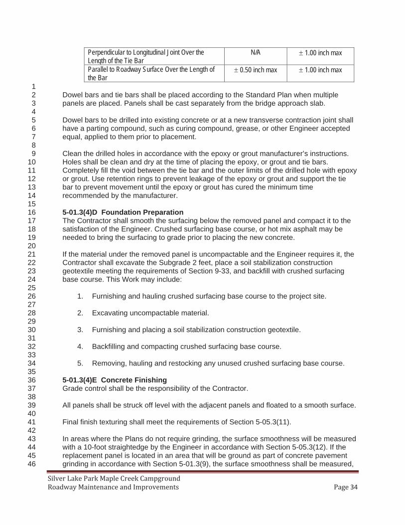
1 Dowel bars and tie bars shall be placed according to the Standard Plan when multiple 2 panels are placed. Panels shall be cast separately from the bridge approach slab. 3 4 Dowel bars to be drilled into existing concrete or at a new transverse contraction joint shall 5 have a parting compound, such as curing compound, grease, or other Engineer accepted 6 equal, applied to them prior to placement. 7 8 Clean the drilled holes in accordance with the epoxy or grout manufacturer’s instructions. 9 Holes shall be clean and dry at the time of placing the epoxy, or grout and tie bars. 10 Completely fill the void between the tie bar and the outer limits of the drilled hole with epoxy 11 or grout. Use retention rings to prevent leakage of the epoxy or grout and support the tie 12 bar to prevent movement until the epoxy or grout has cured the minimum time 13 recommended by the manufacturer. 14 15 5-01.3(4)D Foundation Preparation 16 The Contractor shall smooth the surfacing below the removed panel and compact it to the 17 satisfaction of the Engineer. Crushed surfacing base course, or hot mix asphalt may be 18 needed to bring the surfacing to grade prior to placing the new concrete. 19 20 If the material under the removed panel is uncompactable and the Engineer requires it, the 21 Contractor shall excavate the Subgrade 2 feet, place a soil stabilization construction 22 geotextile meeting the requirements of Section 9-33, and backfill with crushed surfacing 23 base course. This Work may include: 24 25
1. Furnishing and hauling crushed surfacing base course to the project site. 26 27 2. Excavating uncompactable material. 28 29 3. Furnishing and placing a soil stabilization construction geotextile. 30 31 4. Backfilling and compacting crushed surfacing base course. 32 33 5. Removing, hauling and restocking any unused crushed surfacing base course. 34
35 5-01.3(4)E Concrete Finishing 36 Grade control shall be the responsibility of the Contractor. 37 38 All panels shall be struck off level with the adjacent panels and floated to a smooth surface. 39 40 Final finish texturing shall meet the requirements of Section 5-05.3(11). 41 42 In areas where the Plans do not require grinding, the surface smoothness will be measured 43 with a 10-foot straightedge by the Engineer in accordance with Section 5-05.3(12). If the 44 replacement panel is located in an area that will be ground as part of concrete pavement 45 grinding in accordance with Section 5-01.3(9), the surface smoothness shall be measured, 46
35
by the Contractor, in conjunction with the smoothness measurement done in accordance 1 with Section 5-01.3(10). 2 3 5-01.3(4)F Joints 4 All transverse and longitudinal joints shall be sawed and sealed in accordance with Section 5 5-05.3(8). The Contractor may use a hand pushed single blade saw for sawing joints. 6 7 5-01.3(4)G Cracked Panels 8 Replacement panels that crack shall be repaired as specified in Section 5-05.3(22) at no 9 cost to the Contracting Agency. When repairing replacement panels that have cracked, 10 epoxy-coated dowel bars meeting the requirements of Section 9-07.5(1) may be substituted 11 for the corrosion resistant dowel bars specified. 12 13 5-01.3(4)H Opening to Traffic 14 Opening to traffic shall meet the requirements of Section 5-05.3(17). 15
16 5-01.3(5) Partial Depth Spall Repair 17 The second sentence of the third paragraph is revised to read: 18 19
All sandblasting residue shall be removed. 20 21 5-01.3(7) Sealing Existing Concrete Random Cracks 22 The second sentence of the second paragraph is revised to read: 23 24
Immediately prior to sealing, the cracks shall be clean. 25 26 5-01.3(8) Sealing Existing Longitudinal and Transverse Joint 27 The first sentence of the fifth paragraph is revised to read: 28 29
Immediately prior to sealing, the cracks shall be clean. 30 31 5-01.3(10) Pavement Smoothness 32 This section is revised to read: 33 34
Pavement surface smoothness for cement concrete pavement grinding on this project will 35 include International Roughness Index (IRI) testing. Ride quality will be evaluated using the 36 Mean Roughness Index (MRI) calculated by averaging the IRI data for the left and right 37 wheel path within the section. 38 39 Smoothness Testing Equipment and Operator Certification40 Use an inertial profiler and operator that meet the requirements of Section 5-05.3(3)E. 41 42 Surface Smoothness43 Operate the inertial profiler in accordance with AASHTO R 57. Collect two longitudinal 44 traces, one in each wheel path. Collect the control profile at locations designated in Table 2 45 prior to any pavement rehabilitation Work on the areas to be tested. Collect an acceptance 46 profile at locations designated in Table 2 after completion of all cement concrete pavement 47 grinding on the project. Profiles shall be collected in a continuous pass including areas 48 excluded from pay adjustments. Provide notice to the Engineer a minimum of seven 49 calendar days prior to testing. 50
36
1 Table 2
Locations Requiring MRI TestingTravel lanes where cement concrete grinding is shown in the plans
Control profile
Additional locations designated by the Engineer Control profile
Travel lanes with completed cement concrete pavement grinding Acceptance profile
Bridges, approach panels and 0.02 miles before and after bridges and approach panels and other excluded areas within lanes requiring testing
Control and acceptance profile
Ramps, Shoulders and Tapers Do not test 2
Within 30 calendar days after the Contractor’s testing, the Engineer may perform 3 verification testing. If the verification testing shows a difference in MRI greater than the 10 4 percent, the following resolution process will be followed: 5 6
1. The profiles, equipment and procedures will be evaluated to determine the cause 7 of the difference. 8
9 2. If the cause of the discrepancy cannot be resolved the pavement shall be retested 10
with both profilers at a mutually agreed time. The two profilers will test the section 11 within 30 minutes of each other. If the retest shows a difference in MRI equal or 12 greater than the percentages shown in Table 2 of AASHTO R 54 the Engineer’s 13 test results will be used for pavement smoothness acceptance. 14
15 The Contractor shall evaluate profiles for acceptance or corrective action using the current 16 version of ProVAL and provide the results including the profile data in unfiltered electronic 17 Engineering Research Division (ERD) file format to the Engineer within 3 calendar days of 18 completing each days profile testing. If the profile data files are created using an export 19 option in the manufacturer’s software where filter settings can be specified, use the filter 20 settings that were used to create data files for certification. 21 22 Analyze the entire profile. Exclude areas listed in Table 3. 23 24
Table 3 Areas Excluded from MRI Acceptance Requirements
Location Exclude Beginning and end of grinding Pavement within 0.02 mile
Bridges and approach slabs The bridge and approach slab and
0.02 mile from the ends of the bridge or approach slab
Defects in the existing roadway identified by the Contractor that adversely affect the MRI such as
0.01-mile section containing the defect and the 0.01-mile section
following the section with the defect.
37
dips, depressions and wheel path longitudinal joints.1 1The presence of defects is subject to verification by the Engineer
1 Report the MRI results in inches per mile for each 0.01-mile section and each 0.10-mile 2 section. Do not truncate 0.10-mile sections for areas excluded from MRI acceptance 3 requirements. MRI requirements will not apply to 0.10-mile sections with more than three 4 0.01 mile-sections excluded. MRI requirements for the individual 0.01-mile sections shall 5 still apply. The Engineer will verify the analysis. 6 7 The MRI for each 0.10 mile of ground lane will comply with the following: 8 9
Control Profile MRI per 0.10 Mile Maximum MRI of Acceptance Profile per 0.10 Mile
130 inches/mile 78 inches/mile >130 inches/mile 0.6 x Control Profile MRI
10 The MRI for each 0.01 mile of the completed cement concrete grinding shall not exceed 11 160 inches/mile. 12 13 All Work is subject to parallel and transverse 10-foot straightedge requirements, corrective 14 work and disincentive adjustments. 15 16 Surface smoothness of travel lanes including areas subject to MRI testing shall not vary 17 more than inch from the lower edge of a 10-foot straightedge placed on the surface 18 parallel to the centerline. 19 20 The smoothness perpendicular to the centerline will be measured with a 10-foot 21 straightedge within the lanes. There shall be not vertical elevation difference of more than a 22 ¼ inch between lanes. 23 24 Pavement that does not meet these requirements will be subject to corrective Work. All 25 corrective Work shall be completed at no additional expense, including traffic control, to the 26 Contracting Agency. Pavement shall be repaired by one or more of the following methods: 27 28
1. Diamond grinding. 29 30 2. By other method accepted by the Engineer. 31
32 Repair areas shall be re-profiled to ensure they no longer require corrective Work. With 33 concurrence of the Engineer, a 10-foot straight edge may be used in place of the inertial 34 profiler. 35 36 If correction of the roadway as listed above either will not or does not produce satisfactory 37 results as to smoothness or serviceability the Engineer may accept the completed 38 pavement and a credit will be calculated in accordance with Section 5-01.5. Under these 39 circumstances, the decision whether to accept the completed pavement or to require 40 corrective work as described above shall be vested entirely in the Engineer. 41
42
38
5-01.5 Payment 1 This section is supplemented with the following: 2 3
“Grinding Smoothness Compliance Adjustment”, by calculation. 4 Grinding Smoothness Compliance Adjustments will be based on the requirements in 5 Section 5-01.3(10) and the following calculations: 6 7
A smoothness compliance adjustment will be calculated in the sum of minus $100 for 8 each and every section of single traffic lane 0.01 mile in length and $1,000 for each 9 and every section of single traffic lane 0.10 mile in length that does not meet the 10 requirements in Section 5-01.3(10) after corrective Work. 11
12 5-04.AP5 13 Section 5-04, Hot Mix Asphalt 14 January 7, 2019 15
5-04.1 Description 16 The last sentence of the first paragraph is revised to read: 17 18
The manufacture of HMA may include additives or processes that reduce the optimum 19 mixing temperature (Warm Mix Asphalt) or serve as a compaction aid in accordance with 20 these Specifications. 21
22 5-04.2 Materials 23 The reference to “Warm Mix Asphalt Additive” is revised to read “HMA Additive”. 24 25 5-04.2(1) How to Get an HMA Mix Design on the QPL 26 The last bullet in the first paragraph is revised to read: 27 28
• Do not include HMA additives that reduce the optimum mixing temperature or serve as 29 a compaction aid when developing a mix design or submitting a mix design for QPL 30 evaluation. The use of HMA additives is not part of the process for obtaining approval 31 for listing a mix design on the QPL. Refer to Section 5-04.2(2)B. 32
33 In the table, “WSDOT Standard Practice QC-8” is revised to read “WSDOT Standard Practice 34 QC-8 located in the WSDOT Materials Manual M 46-01”. 35 36 5-04.2(1)C Mix Design Resubmittal for QPL Approval 37 Item number 3 of the first paragraph is revised to read: 38 39
3. Changes in modifiers used in the asphalt binder. 40 41 5-04.2(2)B Using Warm Mix Asphalt Processes 42 This section, including title, is revised to read: 43 44
5-04.2(2)B Using HMA Additives45 The Contractor may, at the Contractor’s discretion, elect to use additives that reduce the 46 optimum mixing temperature or serve as a compaction aid for producing HMA. Additives 47
39
include organic additives, chemical additives and foaming processes. The use of Additives 1 is subject to the following: 2 3
• Do not use additives that reduce the mixing temperature in accordance with 4 Section 5-04.3(6) in the production of High RAP/Any RAS mixtures. 5
6 • Before using additives, obtain the Engineer’s approval using WSDOT Form 350-7
076 to describe the proposed additive and process. 8 9
5-04.3(3)A Mixing Plant 10 In item number 5 of the first paragraph, “WSDOT T 168” is revised to read “FOP for AASHTO T 11 168”. 12 13 5-04.3(4) Preparation of Existing Paved Surfaces 14 The first sentence of the fourth paragraph is revised to read: 15 16
Unless otherwise allowed by the Engineer, use cationic emulsified asphalt CSS-1, CSS-1h, 17 or Performance Graded (PG) asphalt for tack coat. 18
19 5-04.3(6) Mixing 20 The first paragraph is revised to read: 21 22
The asphalt supplier shall introduce recycling agent and anti-stripping additive, in the 23 amount designated on the QPL for the mix design, into the asphalt binder prior to shipment 24 to the asphalt mixing plant. 25 26
The seventh paragraph is revised to read: 27 28 Upon discharge from the mixer, ensure that the temperature of the HMA does not exceed 29 the optimum mixing temperature shown on the accepted Mix Design Report by more than 30 25°F, or as allowed by the Engineer. When an additive is included in the manufacture of 31 HMA, do not heat the additive (at any stage of production including in binder storage tanks) 32 to a temperature higher than the maximum recommended by the manufacturer of the 33 additive. 34
35 5-04.3(7) Spreading and Finishing 36 The last row of the table is revised to read: 37 38
3 8 inch 0.25 feet 0.30 feet 39
5-04.3(8) Aggregate Acceptance Prior to Incorporation in HMA 40 The following new paragraph is inserted after the first paragraph: 41
42 The Contracting Agency’s combined aggregate bulk specific gravity (Gsb) blend as shown 43 on the HMA Mix Design will be used for VMA calculations until the Contractor submits a 44 written request for a Gsb test. The new Gsb will be used in the VMA calculations for HMA 45 from the date the Engineer receives the written request for a Gsb retest. The Contractor 46 may request aggregate specific gravity (Gsb) testing be performed by the Contracting 47 Agency twice per project. The Gsb blend of the combined stockpiles will be used to 48
40
calculate voids in mineral aggregate (VMA) of any HMA produced after the new Gsb is 1 determined. 2
3 5-04.3(9)A1 Test Section – When Required, When to Stop 4 The following new row is inserted after the second row in Table 9: 5 6
VMA Minimum PFi of 0.95 based on the criteria in Section 5-04.3(9)B42
None4
7 5-04.3(9)A2 Test Section – Evaluating the HMA Mixture in a Test Section 8 In Table 9a, the test property “Gradation, Asphalt Binder, and Va” is revised to read “Gradation, 9 Asphalt Binder, VMA, and Va” 10 11 In Table 9a, the first column of the third row is revised to read: 12 13
Aggregates: Sand Equivalent
Uncompacted Void Content Fracture
14 5-04.3(9)B3 Mixture Statistical Evaluation – Acceptance Testing 15 In Table 11, “Va” is revised to read “VMA and Va” 16 17 5-04.3(9)B5 Mixture Statistical Evaluation – Composite Pay Factors (CPF) 18 The following new row is inserted above the last row in Table 12: 19 20
Voids in Mineral Aggregate (VMA)
2
21 5-04.3(9)B7 Mixture Statistical Evaluation – Retests 22 The second to last sentence is revised to read: 23 24
The sample will be tested for a complete gradation analysis, asphalt binder content, VMA 25 and Va, and the results of the retest will be used for the acceptance of the HMA mixture in 26 place of the original mixture sublot sample test results. 27
28 5-04.3(10)C1 HMA Compaction Statistical Evaluation – Lots and Sublots 29 The bulleted item in the fourth paragraph is revised to read: 30 31
• For a compaction lot in progress with a compaction CPF less than 0.75 using an LSL = 32 91.5, a new compaction lot will begin at the Contractor’s request after the Engineer is 33 satisfied that material conforming to the Specifications can be produced. See also 34 Section 5-04.3(11)F. 35
36 5-04.3(10)C2 HMA Compaction Statistical Evaluation – Acceptance Testing 37 In the table, “WSDOT FOP for AASHTO T 355” is revised to read “FOP for AASHTO T 355”. 38 39
41
5-04.3(10)C3 HMA Statistical Compaction – Price Adjustments 1 In the first paragraph, “WSDOT FOP for AASHTO T 355” is revised to read “FOP for AASHTO T 2 355”. 3 4 The first sentence in the second paragraph is revised to read: 5 6
For each HMA compaction lot (that is accepted by Statistical Evaluation) which does not 7 meet the criteria in the preceding paragraph, the compaction lot shall be evaluated in 8 accordance with Section 1-06.2(2)D5 to determine the appropriate Composite Pay Factor 9 (CPF). 10
11 The last two paragraphs are revised to read: 12 13
Determine the Compaction Price Adjustment (CPA) from the table below, selecting the 14 equation for CPA that corresponds to the value of CPF determined above. 15 16
Calculating HMA Compaction Price Adjustment (CPA) Value of CPF Equation for Calculating CPA
When CPF > 1.00 CPA = [1.00 x (CPF – 1.00)] x Q x UP
When CPF = 1.00 CPA = $0 When CPF < 1.0 CPA = [0.60 x (CPF – 1.00)] x Q x
UP 17
Where 18 CPA = Compaction Price Adjustment for the compaction lot ($) 19 CPF = Composite Pay Factor for the compaction lot (maximum is 1.05) 20 Q = Quantity in the compaction lot (tons) 21 UP = Unit price of the HMA in the compaction lot ($/ton) 22
23 5-04.3(10)C4 HMA Statistical Compaction – Requests for Retesting 24 The first sentence is revised to read: 25 26
For a compaction sublot that has been tested with a nuclear density gauge that did not 27 meet the minimum of 91.5 percent of the theoretical maximum density in a compaction lot 28 with a CPF below 1.00 and thus subject to a price reduction or rejection, the Contractor 29 may request that a core, taken at the same location as the nuclear density test, be used for 30 determination of the relative density of the compaction sublot. 31
32 5-04.3(13) Surface Smoothness 33 The second to last paragraph is revised to read: 34 35
When concrete pavement is to be placed on HMA, the surface tolerance of the HMA shall 36 be such that no surface elevation lies above the Plan grade minus the specified Plan depth 37 of concrete pavement. Prior to placing the concrete pavement, bring any such irregularities 38 to the required tolerance by grinding or other means allowed by the Engineer. 39
40 5-04.5 Payment 41 The paragraph following the Bid item “Crack Sealing-LF”, per linear foot is revised to read: 42
42
1 The unit Contract price per linear foot for “Crack Sealing-LF” shall be full payment for all 2 costs incurred to perform the Work described in Section 5-04.3(4)A. 3
5-05.1 Description 8 In the first paragraph, “portland cement concrete” is revised to read “cement concrete”. 9 10 5-05.2 Materials 11 In the first paragraph, the reference to “Portland Cement” is revised to read: 12 13
Cement 9-01 14 15 In the first paragraph, the section reference for Concrete Patching Material is revised to read “9-16 20.1”. 17 18 5-05.3(1) Concrete Mix Design for Paving 19 The table title in item number 4 is revised to read Concrete Batch Weights. 20 21 In item 4a, “Portland Cement” is revised to read “Cement”. 22 23 5-05.3(3)E Smoothness Testing Equipment 24 This section is revised to read: 25 26
Inertial profilers shall meet all requirements of AASHTO M 328 and be certified in 27 accordance with AASHTO R 56 within the preceding 12 months. 28 29 The inertial profiler operator shall be certified as required by AASHTO R 56 within three 30 years preceding profile measurement. 31 32 Equipment or operator certification by other states or a profiler certification facility will be 33 accepted provided the certification meets the requirements of AASHTO R 56. 34 Documentation verifying certification by another state shall be submitted to the Engineer a 35 minimum of 14 calendar days prior to profile measurement. Equipment certification 36 documentation shall include the information required by part 8.5 and 8.6 of AASHTO R 56. 37 Operator documentation shall include a statement from the certifying state that indicates 38 the operator is certified to operate the inertial profiler to be used on the project. The 39 decision whether another state’s certification meets the requirements of AASHTO R 56 40 shall be vested entirely in the Engineer. 41
42 5-05.3(4) Measuring and Batching Materials 43 Item number 2 is revised to read: 44 45
2. Batching Materials – On all projects requiring more than 2,500 cubic yards of 46 concrete for paving, the batching plant shall be equipped to proportion aggregates and 47
43
cement by weight by means of automatic and interlocked proportioning devices of 1 accepted type. 2
3 5-05.3(4)A Acceptance of Portland Cement Concrete Pavement 4 This section’s title is revised to read: 5 6
Acceptance of Portland Cement or Blended Hydraulic Cement Concrete Pavement7 8 The first sentence is revised to read: 9 10
Acceptance of portland cement or blended hydraulic cement concrete pavement shall be as 11 provided under statistical or nonstatistical acceptance. 12
13 5-05.3(7) Placing, Spreading, and Compacting Concrete 14 This section’s content is deleted. 15 16 5-05.3(10) Tie Bars and Corrosion Resistant Dowel Bars 17 The first sentence of the last paragraph is revised to read: 18 19
The tie bar holes shall be clean before grouting. 20 21 5-05.3(12) Surface Smoothness 22 This section is revised to read: 23 24
Pavement surface smoothness for this project will include International Roughness Index 25 (IRI) testing. The Contractor shall perform IRI testing on each through lane, climbing lane, 26 and passing lane, greater than 0.25 mile in length and these lanes will be subject to 27 incentive/disincentive adjustments. Ride quality will be evaluated using the Mean 28 Roughness Index (MRI) calculated by averaging the IRI data for the left and right wheel 29 path within the section. 30 31 Ramps, shoulders and tapers will not be included in MRI testing for pavement smoothness 32 and will not be subject to incentive adjustments. All Work is subject to parallel and 33 transverse 10-foot straightedge requirements, corrective work and disincentive 34 adjustments. 35 36 Operate the inertial profiler in accordance with AASHTO R 57. Collect two longitudinal 37 traces, one in each wheel path. Collect profile data after completion of all concrete paving 38 on the project in a continuous pass including areas excluded from pay adjustments. 39 Provide notice to the Engineer a minimum of seven calendar days prior to testing. 40 41 Within 30 calendar days after the Contractor’s testing, the Engineer may perform 42 verification testing. If the verification testing shows a difference in MRI greater than the 43 percentages shown in Table 2 of AASHTO R 54 the following resolution process will be 44 followed: 45 46
1. The profiles, equipment and procedures will be evaluated to determine the cause 47 of the difference. 48
49
44
2. If the cause of the discrepancy cannot be resolved the pavement shall be retested 1 with both profilers at a mutually agreed time. The two profilers will test the section 2 within 30 minutes of each other. If the retest shows a difference in MRI equal or 3 greater than the percentages shown in Table 2 of AASHTO R 54 the Engineer’s 4 test results will be used to establish pay adjustments. 5
6 Surface smoothness of travel lanes not subject to MRI testing will be measured with a 10-7 foot straightedge no later than 5:00 p.m. of the day following the placing of the concrete. 8 The completed surface of the wearing course shall not vary more than inch from the 9 lower edge of a 10-foot straightedge placed on the surface parallel to the centerline. 10 11 Smoothness perpendicular to the centerline will be measured with a 10-foot straightedge 12 across all lanes with the same cross slope, including shoulders when composed of cement 13 concrete pavement. The overlapping 10-foot straightedge measurement shall be 14 discontinued at a point 6 inches from the most extreme outside edge of the finished cement 15 concrete pavement. The completed surface of the wearing course shall not vary more than 16 ¼ inch from the lower edge of a 10-foot straightedge placed on the surface perpendicular to 17 the centerline. Any deviations in excess of the above tolerances shall be corrected. 18 19 The Contractor shall evaluate profiles for acceptance, incentive payments, disincentive 20 payments, or corrective action using the current version of ProVAL and provide the results 21 including the profile data in unfiltered electronic Engineering Research Division (ERD) file 22 format to the Engineer within 2 calendar days of completing testing each section of 23 pavement. If the profile data files are created using an export option in the manufacturer’s 24 software where filter settings can be specified, use the filter settings that were used to 25 create data files for certification. Analyze the entire profile. Exclude any areas specifically 26 identified in the Contract. Exclude from the analysis the first 100 feet after the start of the 27 paving operations and last 100 feet prior to the end of the paving operation, the first 100 28 feet on either side of bridge Structures and bridge approach slab. Report the MRI results in 29 inches per mile for each 52.8 foot section and horizontal distance measurements in project 30 stationing to the nearest foot. Include pay adjustments in the results. The Engineer will 31 verify the analysis. 32 33 Corrective work for pavement smoothness may be taken by the Contractor prior to MRI 34 testing. After completion of the MRI testing the Contractor shall measure the smoothness of 35 each 52.8-foot section with an MRI greater than 125 inches per mile with a 10-foot 36 straightedge within 14 calendar days or as allowed by the Engineer. The Contractor shall 37 identify all locations that require corrective work and provide the straight edge 38 measurements at each location that exceeds the allowable limit to the Engineer. If all 39 measurements in a 52.8-foot section comply with smoothness requirements, the Contractor 40 shall provide the maximum measurement to the Engineer and a statement that corrective 41 work is not required. Unless allowed by the Engineer, corrective work shall be taken by the 42 Contractor for pavement identified by the Contractor or Engineer that does not meet the 43 following requirements: 44 45
1. The completed surface shall be of uniform texture, smooth, uniform as to crown 46 and grade, and free from defects of all kinds. 47
48 2. The completed surface shall not vary more than inch from the lower edge of a 49
10-foot straightedge placed on the surface parallel to the centerline. 50
45
1 3. The completed surface shall vary not more than ¼ inch in 10 feet from the rate of 2
transverse slope shown in the Plans. 3 4 All corrective work shall be completed at no additional expense, including traffic control, to 5 the Contracting Agency. Corrective work shall not begin until the concrete has reached its 6 design strength unless allowed by the Engineer. Pavement shall be repaired by one or 7 more of the following methods: 8 9
1. Diamond grinding; repairs shall not reduce pavement thickness by more than ¼ 10 inch less than the thickness shown in the Plans. When required by the Engineer, 11 the Contractor shall verify the thickness of the concrete pavement by coring. 12 Thickness reduction due to corrective work will not be included in thickness 13 measurements for calculating the Thickness Deficiency in Section 5-05.5(1)A. 14
15 2. Removal and replacement of the cement concrete pavement. 16 17 3. By other method allowed by the Engineer. 18
19 For repairs following MRI testing the repaired area shall be checked by the Contractor with 20 a 10-foot straightedge to ensure it no longer requires corrective work. With concurrence of 21 the Engineer an inertial profiler may be used in place of the 10-foot straight edge. 22 23 If correction of the roadway as listed above either will not or does not produce satisfactory 24 results as to smoothness or serviceability the Engineer may accept the completed 25 pavement and a credit will be calculated in accordance with Section 5-05.5. The credit will 26 be in addition to the price adjustment for MRI. Under these circumstances, the decision 27 whether to accept the completed pavement or to require corrective work as described 28 above shall be vested entirely in the Engineer. 29
30 5-05.3(22) Repair of Defective Pavement Slabs 31 The last sentence of the fourth paragraph is revised to read: 32 33
All sandblasting residue shall be removed. 34 35 5-05.4 Measurement 36 Item number 3 of the second paragraph is revised to read: 37 38
3. The depth shall be determined in accordance with Section 5-05.5(1). The depth utilized 39 to calculate the volume shall not exceed the Plan depth plus 0.04 feet. 40
41 The third paragraph is revised to read: 42 43
The volume of cement concrete pavement in each thickness lot shall equal the measured 44 length × width × thickness measurement. 45
46 The last paragraph is revised to read: 47 48
The calculation for cement concrete compliance adjustment is the volume of concrete 49 represented by the CPF and the Thickness deficiency adjustment. 50
46
1 5-05.5 Payment 2 The paragraph following the Bid item “Cement Conc. Pavement”, per cubic yard is 3 supplemented with the following: 4 5
All costs associated with performing the magnetic pulse induction thickness testing shall be 6 included in the unit Contract price per cubic yard for “Cement Conc. Pavement”. 7
8 The Bid item “Ride Smoothness Compliance Adjustment”, by calculation, and the paragraph 9 following this bid item are revised to read: 10 11
“Ride Smoothness Compliance Adjustment”, by calculation. 12 13 Smoothness Compliance Adjustments will be based on the requirements in Section 5-14 05.3(12) and the following calculations: 15 16
1. Final MRI acceptance and incentive/disincentive payments for pavement 17 smoothness will be calculated as the average of the ten 52.8-foot sections in each 18 528 feet in accordance with the price adjustment schedule. 19
20 a. For sections of a lane that are a minimum of 52.8 feet and less than 528 feet, 21
the price adjustment will be calculated using the average of the 52.8 foot MRI 22 values and the price adjustment prorated for the length of the section. 23
24 b. MRI values per 52.8-feet that were measured prior to corrective work will be 25
included in the 528 foot price adjustment for sections with corrective work. 26 27 2. In addition to the price adjustment for MRI a smoothness compliance adjustment 28
will be calculated in the sum of minus $1000.00 for each and every section of 29 single traffic lane 52.8 feet in length in that does not meet the 10-foot straight 30 edge requirements in Section 5-05.3(12) after corrective Work. 31 32
1 The bid item “Portland Cement Concrete Compliance Adjustment”, by calculation, and the 2 paragraph following this bid item are revised to read: 3 4
“Cement Concrete Compliance Adjustment”, by calculation. 5 6 Payment for “Cement Concrete Compliance Adjustment” will be calculated by multiplying 7 the unit Contract price for the cement concrete pavement, times the volume for adjustment, 8 times the percent of adjustment determined from the calculated CPF and the Deficiency 9 Adjustment listed in Section 5-05.5(1)A. 10
11
49
5-05.5(1) Pavement Thickness 1 This section is revised to read: 2 3
Cement concrete pavement shall be constructed in accordance with the thickness 4 requirements in the Plans and Specifications. Tolerances allowed for Subgrade 5 construction and other provisions, which may affect thickness, shall not be construed to 6 modify such thickness requirements. 7 8 Thickness measurements in each lane paved shall comply with the following: 9 10
Thickness Testing of Cement Concrete Pavement Thickness Lot Size 15 panels maximum
Thickness test location determined by Engineer will select testing locations in accordance with WSDOT TM 716 method B.
Sample method AASHTO T 359
Sample preparation performed by Contractor provides, places, and secures disks in the presence of the Engineer1
Measurement method AASHTO T 359 Thickness measurement performed by Contractor, in the presence of the Engineer2 1Reflectors shall be located at within 0.5 feet of the center of the panel. The Contractor shall supply a sufficient number of 300 mm-diameter round reflectors meeting the requirements of AASHTO T 359 to accomplish the required testing. 2The Contractor shall provide all equipment and materials needed to perform the testing.
11 Thickness measurements shall be rounded to the nearest 0.01 foot. 12 13 Each thickness test location where the pavement thickness is deficient by more than 0.04 14 foot, shall be subject to price reduction or corrective action as shown in Table 2. 15 16
Thickness deficiency > 0.08’ Remove and replace the panels or the panels may be accepted with no payment at the discretion of the Engineer.
17 The price reduction shall be computed by multiplying the percent price reduction in Table 2 18 by the unit Contract price by the volume of pavement represented by the thickness test lot. 19 20 Additional cores may be taken by the Contractor to determine the limits of an area that has 21 a thickness deficiency greater than 0.04 feet. Cores shall be taken at the approximate 22 center of the panel. Only the panels within the limits of the deficiency area as determined 23 by the cores will be subject to a price reduction or corrective action. The cores shall be 24 taken in the presence of the Engineer and delivered to the Engineer for measurement. All 25 costs for the additional cores including filling the core holes with patching material meeting 26 the requirements of Section 9-20 will be the responsibility of the Contractor. 27
28
50
5-05.5(1)A Thickness Deficiency of 0.05 Foot or Less 1 This section, including title, is revised to read: 2 3
5-05.5(1)A Vacant4 5 5-05.5(1)B Thickness Deficiency of More Than 0.05 Foot 6 This section, including title, is revised to read: 7 8
5-05.5(1)B Vacant9 10 6-01.AP6 11 Section 6-01, General Requirements for Structures 12 January 7, 2019 13
This section is supplemented with the following new subsections: 14 15
6-01.16 Repair of Defective Work16 6-01.16(1) General 17 When using repair procedures that are described elsewhere in the Contract 18 Documents, the Working Drawing submittal requirements of this Section shall not 19 apply to those repairs unless noted otherwise. 20 21 Repair procedures for defective Work shall be submitted as Type 2 Working Drawings. 22 Type 2E Working Drawings shall be submitted when required by the Engineer. As an 23 alternative to submitting Type 2 or 2E Working Drawings, defective Work within the 24 limits of applicability of a pre-approved repair procedure may be repaired using that 25 procedure. Repairs using a pre-approved repair procedure shall be submitted as a 26 Type 1 Working Drawing. 27 28 Pre-approved repair procedures shall consist of the following: 29 30
• The procedures listed in Section 6-01.16(2) 31 32 • For precast concrete, repair procedures in the annual plant approval process 33
documents that have been approved for use by the Contracting Agency. 34 35 All Working Drawings for repair procedures shall include: 36
37 • A description of the defective Work including location, extent and pictures 38 39 • Materials to be used in the repair. Repairs using manufactured products shall 40
include written manufacturer recommendations for intended uses of the 41 product, surface preparation, mixing, aggregate extension (if applicable), 42 ambient and surface temperature limits, placement methods, finishing and 43 curing. 44
45 • Construction procedures 46 47 • Plan details of the area to be repaired 48 49
51
• Calculations for Type 2E Working Drawings 1 2 Material manufacturer’s instructions and recommendations shall supersede any 3 conflicting requirements in pre-approved repair procedures. 4 5 The Engineer shall be notified prior to performing any repair procedure and shall be 6 given an opportunity to inspect the repair work being performed. 7 8 6-01.16(2) Pre-Approved Repair Procedures 9
6-01.16(2)A Concrete Spalls and Poor Consolidation (Rock Pockets, 10 Honeycombs, Voids, etc.) 11 This repair shall be limited to the following areas: 12 13
• Areas that are not on top Roadway surfaces (with or without an overlay) 14 including but not limited to concrete bridge decks, bridge approach slabs 15 or cement concrete pavement 16
17 • Areas that are not underwater 18 19 • Areas that are not on precast barrier, except for the bottom 4 inches (but 20
not to exceed 1 inch above blockouts) 21 22 • Areas that do not affect structural adequacy as determined by the 23
Engineer. 24 25 The repair procedure is as follows: 26 27
1. Remove all loose and unsound concrete. Impact breakers shall not 28 exceed 15 pounds in weight when removing concrete adjacent to 29 reinforcement or other embedments and shall not exceed 30 pounds in 30 weight otherwise. Operate impact breakers at angles less than 45 31 degrees as measured from the surface of the concrete to the tool and 32 moving away from the edge of the defective Work. Concrete shall be 33 completely removed from exposed surfaces of existing steel reinforcing 34 bars. If half or more of the circumference of any steel reinforcing bar is 35 exposed, if the reinforcing bar is loose or if the bond to existing concrete 36 is poor then concrete shall be removed at least ¾ inch behind the 37 reinforcing bar. Do not damage any existing reinforcement. Stop work 38 and allow the Engineer to inspect the repair area after removing all loose 39 and unsound concrete. Submit a modified repair procedure when 40 required by the Engineer. 41
42 2. Square the edges of the repair area by cutting an edge perpendicular to 43
the concrete surface around the repair area. The geometry of the repair 44 perimeter shall minimize the edge length and shall be rectangular with 45 perpendicular edges, avoiding reentrant corners. The depth of the cut 46 shall be a minimum of ¾ inch, but shall be reduced if necessary to avoid 47 damaging any reinforcement. For repairs on vertical surfaces, the top 48 edge shall slope up toward the front at a 1-vertical-to-3-horizontal slope. 49
50
52
3. Remove concrete within the repair area to a depth at least matching the 1 cut depth at the edges. Large variations in the depth of removal within 2 short distances shall be avoided. Roughen the concrete surface. The 3 concrete surface should be roughened to at least Concrete Surface 4 Profile (CSP) 5 in accordance with ICRI Guideline No. 310.2R, unless a 5 different CSP is recommended by the patching material manufacturer. 6
7 4. Inspect the concrete repair surface for delaminations, debonding, 8
microcracking and voids using hammer tapping or a chain drag. Remove 9 any additional loose or unsound concrete in accordance with steps 1 10 through 3. 11
12 5. Select a patching material in accordance with Section 9-20.2 that is 13
appropriate for the repair location and thickness. The concrete patching 14 material shall be pumpable or self-consolidating as required for the type 15 of placement that suits the repair. The patching material shall have a 16 minimum compressive strength at least equal to the specified 17 compressive strength of the concrete. 18
19 6. Prepare the concrete surface and reinforcing steel in accordance with 20
the patching material manufacturer’s recommendations. At a minimum, 21 clean the concrete surfaces (including perimeter edges) and reinforcing 22 steel using oil-free abrasive blasting or high-pressure (minimum 5,000 23 psi) water blasting. All dirt, dust, loose particles, rust, laitance, oil, film, 24 microcracked/bruised concrete or foreign material of any sort shall be 25 removed. Damage to the epoxy coating on steel reinforcing bars shall be 26 repaired in accordance with Section 6-02.3(24)H. 27
28 7. Construct forms if necessary, such as for patching vertical or overhead 29
surfaces or where patching extends to the edge or corner of a 30 placement. 31
32 8. When recommended by the patching material manufacturer, saturate the 33
concrete in the repair area and remove any free water at the concrete 34 surface to obtain a saturated surface dry (SSD) substrate. When 35 recommended by the patching material manufacturer, apply a primer, 36 scrub coat or bonding agent to the existing surfaces. Epoxy bonding 37 agents, if used, shall be Type II or Type V in accordance with Section 9-38 26.1. 39
40 9. Place and consolidate the patching material in accordance with the 41
manufacturer’s recommendations. Work the material firmly into all 42 surfaces of the repair area with sufficient pressure to achieve proper 43 bond to the concrete. 44
45 10. The patching material shall be textured, cured and finished in 46
accordance with the patching material manufacturer’s recommendations 47 and/or the requirements for the repaired component. Protect the newly 48 placed patch from vibration in accordance with Section 6-02.3(6)D. 49
50
53
11. When the completed repair does not match the existing concrete color 1 and will be visible to the public, a sand and cement mixture that is color 2 matched to the existing concrete shall be rubbed, brushed, or applied to 3 the surface of the patching material and the concrete. 4
5 6-01.10 Utilities Supported by or Attached to Bridges 6 In the third paragraph, “Federal Standard 595” is revised to read “SAE AMS Standard 595”. 7 8 6-01.12 Final Cleanup 9 The second sentence of the first paragraph is revised to read: 10 11
Structure decks shall be clean. 12 13 The second paragraph is deleted. 14 15 6-02.AP6 16 Section 6-02, Concrete Structures 17 January 7, 2019 18
6-02.1 Description 19 The first sentence is revised to read: 20 21
This Work consists of the construction of all Structures (and their parts) made of portland 22 cement or blended hydraulic cement concrete with or without reinforcement, including 23 bridge approach slabs. 24
25 6-02.2 Materials 26 In the first paragraph, the references to “Portland Cement” and “Aggregates for Portland 27 Cement Concrete” are revised to read: 28 29
Cement 9-01 30 Aggregates for Concrete 9-03.1 31
32 6-02.3(2) Proportioning Materials 33 The second paragraph is revised to read: 34 35
Unless otherwise specified, the Contractor shall use Type I or II portland cement or blended 36 hydraulic cement in all concrete as defined in Section 9-01.2(1). 37
38 6-02.3(2)A Contractor Mix Design 39 The last sentence of the last paragraph is revised to read: 40 41
For all other concrete, air content shall be a minimum of 4.5 percent and a maximum of 7.5 42 percent for all concrete placed above the finished ground line unless noted otherwise. 43
44 6-02.3(2)A1 Contractor Mix Design for Concrete Class 4000D 45 Item number 5 of the first paragraph is deleted. 46 47
54
Item number 6 of the first paragraph (after the preceding Amendment is applied) is renumbered 1 to 5. 2 3 6-02.3(2)B Commercial Concrete 4 The second paragraph is revised to read: 5 6
Where concrete Class 3000 is specified for items such as, culvert headwalls, plugging 7 culverts, concrete pipe collars, pipe anchors, monument cases, Type PPB, PS, I, FB and 8 RM signal standards, pedestals, cabinet bases, guardrail anchors, fence post footings, 9 sidewalks, concrete curbs, curbs and gutters, and gutters, the Contractor may use 10 commercial concrete. If commercial concrete is used for sidewalks, concrete curbs, curbs 11 and gutters, and gutters, it shall have a minimum cementitious material content of 564 12 pounds per cubic yard of concrete, shall be air entrained, and the tolerances of Section 6-13 02.3(5)C shall apply. 14
15 6-02.3(4) Ready-Mix Concrete 16 The first sentence of the first paragraph is revised to read: 17 18
All concrete, except lean concrete, shall be batched in a prequalified manual, semi-19 automatic, or automatic plant as described in Section 6-02.3(4)A. 20
21 6-02.3(4)D Temperature and Time For Placement 22 The following is inserted after the first sentence of the first paragraph: 23 24
The upper temperature limit for placement for Class 4000D concrete may be increased to a 25 maximum of 80°F if allowed by the Engineer. 26
27 6-02.3(5)C Conformance to Mix Design 28 Item number 1 of the second paragraph is revised to read: 29 30
1. Cement weight plus 5 percent or minus 1 percent of that specified in the mix design. 31 32 6-02.3(6)A1 Hot Weather Protection 33 The first paragraph is revised to read: 34 35
The Contractor shall provide concrete within the specified temperature limits. Cooling of the 36 coarse aggregate piles by sprinkling with water is permitted provided the moisture content 37 is monitored, the mixing water is adjusted for the free water in the aggregate and the 38 coarse aggregate is removed from at least 1 foot above the bottom of the pile. Sprinkling of 39 fine aggregate piles with water is not allowed. Refrigerating mixing water or replacing all or 40 part of the mixing water with crushed ice is permitted, provided the ice is completely melted 41 by placing time. 42
43 The second sentence of the second paragraph is revised to read: 44 45
These surfaces include forms, reinforcing steel, steel beam flanges, and any others that 46 touch the concrete. 47
48
55
6-02.3(7) Vacant 1 This section, including title, is revised to read: 2 3
6-02.3(7) Tolerances4 Unless noted otherwise, concrete construction tolerances shall be in accordance with this 5 section. Tolerances in this section do not apply to cement concrete pavement. 6 7 Horizontal deviation of roadway crown points, cross-slope break points, and curb, barrier or 8 railing edges from alignment or work line: ±1.0 inch 9 10 Deviation from plane: ±0.5 inch in 10 feet 11 12 Deviation from plane for roadway surfaces: ±0.25 inch in 10 feet 13 14 Deviation from plumb or specified batter: ±0.5 inch in 10 feet, but not to exceed a total of 15 ±1.5 inches 16 17 Vertical deviation from profile grade for roadway surfaces: ±1 inch 18 19 Vertical deviation of top surfaces (except roadway surfaces): ±0.75 inch 20 21 Thickness of bridge decks and other structural slabs not at grade: ±0.25 inch 22 23 Length, width and thickness of elements such as columns, beams, crossbeams, 24 diaphragms, corbels, piers, abutments and walls, including dimensions to construction 25 joints in initial placements: +0.5 inch, -0.25 inch 26 27 Length, width and thickness of spread footing foundations: +2 inches, -0.5 inch 28 29 Horizontal location of the as-placed edge of spread footing foundations: The greater of ±2% 30 of the horizontal dimension of the foundation perpendicular to the edge and ±0.5 inch. 31 However, the tolerance shall not exceed ±2 inches. 32 33 Location of opening, insert or embedded item at concrete surface: ±0.5 inch 34 35 Cross-sectional dimensions of opening: ±0.5 inch 36 37 Bridge deck, bridge approach slab, and bridge traffic barrier expansion joint gaps with a 38 specified temperature range, measured at a stable temperature: ±0.25 inch 39 40 Horizontal deviation of centerline of bearing pad, oak block or other bearing assembly: 41 ±0.125 inch 42 43 Horizontal deviation of centerline of supported element from centerline of bearing pad, oak 44 block or other bearing assembly ±0.25 inch 45 46 Vertical deviation of top of bearing pad, oak block or other bearing assembly: ±0.125 inch 47
48 6-02.3(10)C Finishing Equipment 49 The first paragraph is revised to read: 50
56
1 The finishing machine shall be self-propelled and be capable of forward and reverse 2 movement under positive control. The finishing machine shall be equipped with augers and 3 a rotating cylindrical single or double drum screed. The finishing machine shall have the 4 necessary adjustments to produce the required cross section, line, and grade. The finishing 5 machine shall be capable of raising the screeds, augers, and any other parts of the 6 finishing mechanical operation to clear the screeded surface, and returning to the specified 7 grade under positive control. Unless otherwise allowed by the Engineer, a finishing 8 machine manufacturer technical representative shall be on site to assist the first use of the 9 machine on the Contract. 10
11 The first sentence of the second paragraph is revised to read: 12 13
For bridge deck widening of 20 feet or less, and for bridge approach slabs, or where jobsite 14 conditions do not allow the use of the conventional configuration finishing machines, or 15 modified conventional machines as described above; the Contractor may submit a Type 2 16 Working Drawing proposing the use of a hand-operated motorized power screed such as a 17 “Texas” or “Bunyan” screed. 18
19 6-02.3(10)D4 Monitoring Bridge Deck Concrete Temperature After Placement 20 This section, including title, is revised to read: 21 22
6-02.3(10)D4 Vacant23 24 6-02.3(10)D5 Bridge Deck Concrete Finishing and Texturing 25 In the third subparagraph of the first paragraph, the last sentence is revised to read: 26 27
The Contractor shall texture the bridge deck surface to within 3-inches minimum and 24-28 inches maximum of the edge of concrete at expansion joints, within 1-foot minimum and 2-29 feet maximum of the curb line, and within 3-inches minimum and 9-inches maximum of the 30 perimeter of bridge drain assemblies. 31
32 6-02.3(10)F Bridge Approach Slab Orientation and Anchors 33 The second to last paragraph is revised to read: 34 35
The compression seal shall be a 2½ inch wide gland and shall conform to Section 9-36 04.1(4). 37
38 The last paragraph is deleted. 39 40 6-02.3(13)A Strip Seal Expansion Joint System 41 In item number 3 of the third paragraph, “Federal Standard 595” is revised to read “SAE AMS 42 Standard 595”. 43 44 6-02.3(13)B Compression Seal Expansion Joint System 45 The first paragraph is revised to read: 46 47
Compression seal glands shall conform to Section 9-04.1(4) and be sized as shown in the 48 Plans. 49
57
1 6-02.3(14)C Pigmented Sealer for Concrete Surfaces 2 This section is supplemented with the following new paragraph: 3 4
Pigmented Sealer Materials shall be a product listed in the current WSDOT Qualified 5 Products List (QPL). If the pigmented sealer material is not listed in the current WSDOT 6 QPL, a sample shall be submitted to the State Materials Laboratory in Tumwater for 7 evaluation and acceptance in accordance with Section 9-08.3. 8
9 6-02.3(20) Grout for Anchor Bolts and Bridge Bearings 10 The second, third and fourth paragraphs are revised to read: 11 12
Grout shall be a workable mix with a viscosity that is suitable for the intended application. 13 Grout shall not be placed outside of the manufacturer recommended range of thickness. 14 The Contractor shall receive concurrence from the Engineer before using the grout. 15 16 Field grout cubes and cylinders shall be fabricated and tested in accordance with Section 17 9-20.3 when requested by the Engineer, but not less than once per bridge pier or once per 18 day. 19 20 Before placing grout, the substrate on which it is to be placed shall be prepared as 21 recommended by the manufacturer to ensure proper bonding. The grout shall be cured as 22 recommended by the manufacturer. The grout may be loaded when a minimum of 4,000 23 psi compressive strength is attained. 24
25 The fifth paragraph is deleted. 26 27 6-02.3(23) Opening to Traffic 28 This section is supplemented with the following new paragraph: 29 30
After curing bridge approach slabs in accordance with Section 6-02.3(11), the 31 bridge approach slabs may be opened to traffic when a minimum compressive strength 32 of 2,500 psi is achieved. 33
34 6-02.3(24)C Placing and Fastening 35 This section is revised to read: 36 37
The Contractor shall position reinforcing steel as the Plans require and shall ensure that the 38 steel is set within specified tolerances. Adjustments to reinforcing details outside of 39 specified tolerances to avoid interferences and for other purposes are acceptable when 40 approved by the Engineer. 41 42 When spacing between bars is 1 foot or more, they shall be tied at all intersections. When 43 spacing is less than 1 foot, every other intersection shall be tied. If the Plans require 44 bundled bars, they shall be tied together with wires at least every 6 feet. All epoxy-coated 45 bars in the top mat of the bridge deck shall be tied at all intersections, however they may be 46 tied at alternate intersections when spacing is less than 1 foot in each direction and they 47 are supported by continuous supports meeting all other requirements of supports for epoxy-48 coated bars. Other epoxy-coated bars shall also be tied at all intersections, but shall be tied 49 at alternate intersections when spacing is less than 1 foot in each direction. Wire used for 50
58
tying epoxy-coated reinforcing steel shall be plastic coated. Tack welding is not permitted 1 on reinforcing steel. 2 3 Abrupt bends in the steel are permitted only when one steel member bends around 4 another. Vertical stirrups shall pass around main reinforcement or be firmly attached to it. 5 6 For slip-formed concrete, the reinforcing steel bars shall be tied at all intersections and 7 cross braced to keep the cage from moving during concrete placement. Cross bracing shall 8 be with additional reinforcing steel. Cross bracing shall be placed both longitudinally and 9 transversely. 10 11 After reinforcing steel bars are placed in a traffic or pedestrian barrier and prior to slip-form 12 concrete placement, the Contractor shall check clearances and reinforcing steel bar 13 placement. This check shall be accomplished by using a template or by operating the slip-14 form machine over the entire length of the traffic or pedestrian barrier. All clearance and 15 reinforcing steel bar placement deficiencies shall be corrected by the Contractor before 16 slip-form concrete placement. 17
18 Precast concrete supports (or other accepted devices) shall be used to maintain the 19 concrete coverage required by the Plans. The precast concrete supports shall: 20
21 1. Have a bearing surface measuring not greater than 2 inches in either dimension, and 22 23 2. Have a compressive strength equal to or greater than that of the concrete in which 24
they are embedded. 25 26
In slabs, each precast concrete support shall have either: (1) a grooved top that will hold 27 the reinforcing bar in place, or (2) an embedded wire that protrudes and is tied to the 28 reinforcing steel. If this wire is used around epoxy-coated bars, it shall be coated with 29 plastic. 30
31 Precast concrete supports may be accepted based on a Manufacturer’s Certificate of 32 Compliance. 33
34 In lieu of precast concrete supports, the Contractor may use metal or all-plastic supports to 35 hold uncoated bars. Any surface of a metal support that will not be covered by at least ½ 36 inch of concrete shall be one of the following: 37 38
1. Hot-dip galvanized after fabrication in keeping with AASHTO M232 Class D; 39 40 2. Coated with plastic firmly bonded to the metal. This plastic shall be at least 3 32 41
inch thick where it touches the form and shall not react chemically with the 42 concrete when tested in the State Materials Laboratory. The plastic shall not 43 shatter or crack at or above -5°F and shall not deform enough to expose the metal 44 at or below 200°F; or 45
46 3. Stainless steel that meet the requirements of ASTM A493, Type 302. Stainless 47
steel chair supports are not required to be galvanized or plastic coated. 48 49
59
In lieu of precast concrete supports, epoxy-coated reinforcing bars may be supported by 1 one of the following: 2 3
1. Metal supports coated entirely with a dielectric material such as epoxy or plastic, 4 5 2. Other epoxy-coated reinforcing bars, or 6 7 3. All-plastic supports. 8
9 Damaged coatings on metal bar supports shall be repaired prior to placing concrete. 10 11 All-plastic supports shall be lightweight, non-porous, and chemically inert in concrete. All-12 plastic supports shall have rounded seatings, shall not deform under load during normal 13 temperatures, and shall not shatter or crack under impact loading in cold weather. All-14 plastic supports shall be placed at spacings greater than 1 foot along the bar and shall 15 have at least 25 percent of their gross place area perforated to compensate for the 16 difference in the coefficient of thermal expansion between plastic and concrete. The shape 17 and configuration of all-plastic supports shall permit complete concrete consolidation in and 18 around the support. 19 20 A “mat” is two adjacent and perpendicular layers of reinforcing steel. In bridge decks, top 21 and bottom mats shall be supported adequately enough to hold both in their proper 22 positions. If bar supports directly support, or are directly supported on No. 4 bars, they shall 23 be spaced at not more than 3-foot intervals (or not more than 4-foot intervals for bars No. 5 24 and larger). Wire ties to girder stirrups shall not be considered as supports. To provide a 25 rigid mat, the Contractor shall add other supports and tie wires to the top mat as needed. 26 27 Unless noted otherwise, the minimum concrete cover for main reinforcing bars shall be: 28 29
3 inches to a concrete surface deposited against earth without intervening forms. 30 31 2½ inches to the top surface of a concrete bridge deck or bridge approach slab. 32 33 2 inches to a concrete surface when not specified otherwise in this section or in the 34 Contract documents. 35 36 1½ inches to a concrete barrier or curb surface. 37
38 Except for top cover in bridge decks and bridge approach slabs, minimum concrete cover 39 to ties and stirrups may be reduced by ½ inch but shall not be less than 1 inch. Minimum 40 concrete cover shall also be provided to the outermost part of mechanical splices and 41 headed steel reinforcing bars. 42 43 Reinforcing steel bar location, concrete cover and clearance shall not vary more than the 44 following tolerances from what is specified in the Contract documents: 45 46
Reinforcing bar location for members 12 inches or less in thickness: ±0.25 inch 47 48 Reinforcing bar location for members greater than 12 inches in thickness: ±0.375 inch 49 50
60
Reinforcing bar location for bars placed at equal spacing within a plane: the greater of 1 either ±1 inch or ±1 bar diameter within the plane. The total number of bars shall not 2 be fewer than that specified. 3 4 The clearance between reinforcement shall not be less than the greater of the bar 5 diameter or 1 inch for unbundled bars. For bundled bars, the clearance between 6 bundles shall not be less than the greater of 1 inch or a bar diameter derived from the 7 equivalent total area of all bars in the bundle. 8 9 Longitudinal location of bends and ends of bars: ±1 inch 10 11 Embedded length of bars and length of bar lap splices: 12 13
No. 3 through No. 11: -1 inch 14 15 No. 14 through No. 18: -2 inches 16
17 Concrete cover measured perpendicular to concrete surface (except for the top 18 surface of bridge decks, bridge approach slabs and other roadway surfaces): ±0.25 19 inch 20 21 Concrete cover measured perpendicular to concrete surface for the top surface of 22 bridge decks, bridge approach slabs and other roadway surfaces: +0.25 inch, -0 inch 23
24 Before placing any concrete, the Contractor shall: 25 26
1. Clean all mortar from reinforcement, and 27 28 2. Obtain the Engineer’s permission to place concrete after the Engineer has 29
inspected the placement of the reinforcing steel. (Any concrete placed without the 30 Engineer’s permission shall be rejected and removed.) 31
32 6-02.3(25)H Finishing 33 The last paragraph is revised to read: 34 35
The Contractor may repair defects in prestressed concrete girders in accordance with 36 Section 6-01.16. 37
38 6-02.3(25)I Fabrication Tolerances 39 Item number 12 of the first paragraph is revised to read: 40 41
12. Stirrup Projection from Top of Girder: 42 43
Wide flange thin deck and slab girders: ½ inch 44 45 All other girders: ¾ inch 46
47 6-02.3(27) Concrete for Precast Units 48 The last sentence of the first paragraph is revised to read: 49
61
1 Type III portland cement or blended hydraulic cement is permitted to be used in precast 2 concrete units. 3
4 6-02.3(28)B Casting 5 In the second paragraph, the reference to Section 6-02.3(25)B is revised to read Section 6-6 02.3(25)C. 7 8 6-02.3(28)D Contractors Control Strength 9 In the first paragraph, “WSDOT FOP for AASHTO T 23” is revised to read “FOP for AASHTO T 10 23”. 11 12 6-02.3(28)E Finishing 13 This section is supplemented with the following: 14 15
The Contractor may repair defects in precast panels in accordance with Section 6-01.16. 16 17 6-03.AP6 18 Section 6-03, Steel Structures 19 January 7, 2019 20
6-03.2 Materials 21 In the first paragraph, the material reference for Paints is revised to read: 22 23
Paints and Related Materials 9-08 24 25 6-03.3(25)A3 Ultrasonic Inspection 26 The first paragraph (up until the colon) is revised to read: 27 28
Complete penetration groove welds on plates 5/16 inch and thicker in the following welded 29 assemblies or Structures shall be 100 percent ultrasonically inspected: 30
31 6-03.3(33) Bolted Connections 32 The first paragraph is supplemented with the following: 33 34
After final tightening of the fastener components, the threads of the bolts shall at a 35 minimum be flush with the end of the nut. 36
37 The following is inserted after the third sentence of the fourth paragraph: 38 39
When galvanized bolts are specified, tension-control galvanized bolts are not permitted. 40 41 6-05.AP6 42 Section 6-05, Piling 43 January 2, 2018 44
6-05.3(9)A Pile Driving Equipment Approval 45 The fourth sentence of the second paragraph is revised to read: 46 47
62
For prestressed concrete piles, the allowable driving stress in kips per square inch shall be 1 plus prestress in tension, and 0.85f’c minus prestress in compression, where f’c 2
is the concrete compressive strength in kips per square inch. 3 4 6-07.AP6 5 Section 6-07, Painting 6 January 7, 2019 7
6-07.1 Description 8 The first sentence is revised to read: 9 10
This work consists of containment, surface preparation, shielding adjacent areas from work, 11 testing and disposing of debris, furnishing and applying paint, and cleaning up after painting 12 is completed. 13
14 6-07.2 Materials 15 The material reference for Paint is revised to read: 16 17
Paint and Related Materials 9-08 18 19 6-07.3(1)A Work Force Qualifications for Shop Application of Paint 20 This section is supplemented with the following new sentence: 21 22
The work force may be accepted based on the approved facility. 23 24 6-07.3(1)B Work Force Qualifications for Field Application of Paint 25 The first two paragraphs are revised to read: 26 27
The Contractor preparing the surface and applying the paint shall be certified under SSPC28 QP 1 or NACE International Institute Contractor Accreditation Program (NIICAP) AS 1. 29 30 The Contractor removing and otherwise disturbing existing paint containing lead and other 31 hazardous materials shall be certified under SSPC-QP 2, Category A or NIICAP AS 2. 32
33 The third paragraph (up until the colon) is revised to read: 34 35
In lieu of the above SSPC or NIICAP certifications, the Contractor performing the specified 36 work shall complete both of the following actions: 37
38 Item number 2 of the third paragraph is revised to read: 39 40
2. The Contractor’s quality control inspector(s) for the project shall be NACE-certified CIP 41 Level 3 or SSPC Protective Coating Inspector (PCI) Level 3. 42
43 6-07.3(2) Submittals 44 The first paragraph is supplemented with the following: 45 46
Each component of the plan shall identify the specification section it represents. 47 48
63
6-07.3(2)B Contractor’s Quality Control Program Submittal Component 1 The numbered list in the first paragraph is revised to read: 2 3
1. Description of the inspection procedures, tools, techniques and the acceptance criteria 4 for all phases of work. 5
6 2. Procedure for implementation of corrective action for non-conformance work. 7 8 3. The paint system manufacturer’s recommended methods of preventing defects. 9 10 4. The Contractor’s frequency of quality control inspection for each phase of work. 11 12 5. Example of each completed form(s) of the daily quality control report used to document 13
the inspection work and tests performed by the Contractor’s quality control personnel. 14 15 6-07.3(2)C Paint System Manufacturer and Paint System Information Submittal 16 Component17 Item number 1 is revised to read: 18 19
1. Product data sheets and Safety Data Sheets (SDS) on the paint materials, paint 20 preparation, and paint application, as specified by the paint manufacturer, including: 21
22 a. All application instructions, including the mixing and thinning directions. 23 24 b. Recommended spray nozzles and pressures. 25 26 c. Minimum and maximum drying time between coats. 27 28 d. Restrictions on temperature and humidity. 29 30 e. Repair procedures for shop and field applied coatings. 31 32 f. Maximum dry film thickness for each coat. 33 34 g. Minimum wet film thickness for each coat to achieve the specified minimum dry 35
film thickness. 36 37 6-07.3(2)D Hazardous Waste Containment, Collection, Testing, and Disposal 38 Submittal Component 39 The first paragraph (up until the colon) is revised to read: 40 41
The hazardous waste containment, collection, testing, and disposal shall meet all Federal 42 and State requirements, and the submittal component of the painting plan shall include the 43 following: 44
45 6-07.3(2)E Cleaning and Surface Preparation Submittal Component 46 Item 1(b) of the first paragraph is revised to read:: 47 48
64
b. Type, manufacturer, and brand of abrasive blast material and all associated additives, 1 including Safety Data Sheets (SDS). 2
3 6-07.3(3)B Quality Control and Quality Assurance for Field Application of Paint 4 The last sentence of the first paragraph (excluding the numbered list) is revised to read: 5 6
The Contractor’s quality control operations shall include a minimum monitoring and 7 documenting the following for each working day: 8
9 Item number 1 in the fourth paragraph is revised to read: 10 11
1. Environmental conditions for painting in accordance with ASTM E 337. 12 13 Item number 4 in the fourth paragraph is revised to read: 14 15
4. Pictorial of surface preparation guides in accordance with SSPC-VIS 1, 3, 4, and 5. 16 17 Item number 5 in the fourth paragraph is revised to read: 18 19
5. Surface profile by Keanne-Tator comparator in accordance with ASTM D 4417 and 20 SSPC PA17. 21
22 6-07.3(4) Paint System Manufacturer’s Technical Representative 23 This section is revised to read: 24 25
The paint system manufacturer’s representative shall be present at the jobsite for the pre-26 painting conference and for the first day of paint application, and shall be available to the 27 Contractor and Contracting Agency for consultation for the full project duration. 28
29 6-07.3(5) Pre-Painting Conference 30 The second paragraph is revised to read: 31 32
If the Contractor’s key personnel change between any work operations, an additional 33 conference shall be held if requested by the Engineer. 34
35 6-07.3(6)A Paint Containers 36 In item number 2 of the first paragraph, “Federal Standard 595” is revised to read “SAE AMS 37 Standard 595”. 38 39 6-07.3(6)B Paint Storage 40 Item number 2 of the second paragraph is revised to read: 41 42
2. The Contractor shall monitor and document daily the paint material storage facility with 43 a high-low recording thermometer device. 44
45 6-07.3(7) Paint Sampling and Testing 46 The first two paragraphs are revised to read: 47 48
65
The Contractor shall provide the Engineer 1 quart of each paint representing each lot. 1 Samples shall be accompanied with a Safety Data Sheet. 2 3 If the quantity of paint required for each component of the paint system for the entire project 4 is 20 gallons or less, then the paint system components will be accepted as specified in 5 Section 9-08.1(7). 6
7 6-07.3(8)A Paint Film Thickness Measurement Gages 8 The first paragraph is revised to read: 9 10
Paint dry film thickness measurements shall be performed with either a Type 1 pull-off gage 11 or a Type 2 electronic gage as specified in SSPC Paint Application Specification No. 2, 12 Procedure for Determining Conformance to Dry Coating Thickness Requirements. 13
14 6-07.3(9) Painting New Steel Structures 15 The last sentence of the second paragraph is revised to read: 16 17
Welded shear connectors are not required to painted. 18 19 The last paragraph is revised to read: 20 21
Temporary attachments or supports for scaffolding, containment or forms shall not damage 22 the paint system. 23
24 6-07.3(9)A Paint System 25 The first paragraph is revised to read: 26 27
The paint system applied to new steel surfaces shall consist of the following: 28 29
43 The following new paragraph is inserted after the first paragraph: 44 45
Paints and related materials shall be products listed in the current WSDOT Qualified 46 Products List (QPL). Component based paint systems shall be listed on the QPL in the 47 applicable sections of Section 9-08. Performance based systems shall be listed on the 48 current Northeast Protective Coatings Committee (NEPCOAT) Qualified Products List “A” 49 as listed on the WSDOT QPL in Section 9-08.1(2)M. If the paint and related materials for 50
66
the component based system is not listed in the current WSDOT QPL, a sample shall be 1 submitted to the State Materials Laboratory in Tumwater for evaluation and acceptance in 2 accordance with Section 9-08. 3
4 6-07.3(9)C Mixing and Thinning Paint 5 This section is revised to read: 6 7
The Contractor shall thoroughly mix paint in accordance with the manufacturer’s written 8 recommendations and by mechanical means to ensure a uniform and lump free 9 composition. Paint shall not be mixed by means of air stream bubbling or boxing. Paint 10 shall be mixed in the original containers and mixing shall continue until all pigment or 11 metallic powder is in suspension. Care shall be taken to ensure that the solid material that 12 has settled to the bottom of the container is thoroughly dispersed. After mixing, the 13 Contractor shall inspect the paint for uniformity and to ensure that no unmixed pigment or 14 lumps are present. 15 16 Catalysts, curing agents, hardeners, initiators, or dry metallic powders that are packaged 17 separately may be added to the base paint in accordance with the paint manufacturer’s 18 written recommendations and only after the paint is thoroughly mixed to achieve a uniform 19 mixture with all particles wetted. The Contractor shall then add the proper volume of curing 20 agent to the correct volume of base and mix thoroughly. The mixture shall be used within 21 the pot life specified by the manufacturer. Unused portions shall be discarded at the end of 22 each work day. Accelerants are not permitted except as allowed by the Engineer. 23 24 The Contractor shall not add additional thinner at the application site except as allowed by 25 the Engineer. The amount and type of thinner, if allowed, shall conform to the 26 manufacturer’s specifications. If recommended by the manufacturer and allowed by the 27 Engineer, a measuring cup shall be used for the addition of thinner to any paint with 28 graduations in ounces. No un-measured addition of thinner to paint will be allowed. Any 29 paint found to be thinned by unacceptable methods will be rejected. 30 31 When recommended by the manufacturer, the Contractor shall constantly agitate paint 32 during application by use of paint pots equipped with mechanical agitators. 33 34 The Contractor shall strain all paint after mixing to remove undesirable matter, but without 35 removing the pigment or metallic powder. 36 37 Paint shall be stored and mixed in a secure, contained location to eliminate the potential for 38 spills into State waters and onto the ground and highway surfaces. 39
40 6-07.3(9)D Coating Thickness 41 This section is revised to read: 42 43
Dry film thickness shall be measured in accordance with SSPC Paint Application 44 Specification No. 2, Procedure for Determining Conformance to Dry Coating Thickness 45 Requirements. 46 47 The minimum dry film thickness of the primer coat shall not be less than 2.5 mils. 48 49
67
The minimum dry film thickness of each coat (combination of intermediate and intermediate 1 stripe, and top) shall be not less than 3.0 mils. 2 3 The dry film thickness of each coat shall not be thicker than the paint manufacturer’s 4 recommended maximum thickness. 5 6 The minimum wet film thickness of each coat shall be specified by the paint manufacturer 7 to achieve the minimum dry film thickness. 8 9 Film thickness, wet and dry, will be measured by gages conforming to Section 6-07.3(8)A. 10 11 Wet measurements will be taken immediately after the paint is applied in accordance with 12 ASTM D4414. Dry measurements will be taken after the coating is dry and hard in 13 accordance with SSPC Paint Application Specification No. 2. 14 15 Each painter shall be equipped with wet film thickness gages and shall be responsible for 16 performing frequent checks of the paint film thickness throughout application. 17 18 Coating thickness measurements may be made by the Engineer after the application of 19 each coat and before the application of the succeeding coat. In addition, the Engineer may 20 inspect for uniform and complete coverage and appearance. One hundred percent of all 21 thickness measurements shall meet or exceed the minimum wet film thickness. In areas 22 where wet film thickness measurements are impractical, dry film thickness measurements 23 may be made. If a question arises about an individual coat’s thickness or coverage, it may 24 be verified by the use of a Tooke gage in accordance with ASTM D4138. 25 26 If the specified number of coats does not produce a combined dry film thickness of at least 27 the sum of the thicknesses required per coat, if an individual coat does not meet the 28 minimum thickness, or if visual inspection shows incomplete coverage, the coating system 29 will be rejected and the Contractor shall discontinue painting and surface preparation 30 operations and shall submit a Type 2 Working Drawing of the repair proposal. The repair 31 proposal shall include documentation demonstrating the cause of the less-than-minimum 32 thickness, along with physical test results, as necessary, and modifications to Work 33 methods to prevent similar results. The Contractor shall not resume painting or surface 34 preparation operations until receiving the Engineer’s acceptance of the completed repair. 35
36 6-07.3(9)E Surface Temperature Requirements Prior to Application of Paint 37 This section, including title, is revised to read: 38 39
6-07.3(9)E Environmental Condition Requirements Prior to Application of Paint40 Paint shall be applied only during periods when: 41 42
1. Air and steel temperatures are in accordance with the paint manufacturer’s 43 recommendations but in no case less than 35°F nor greater than 115°F. 44
45 2. Steel surface temperature is a minimum of 5°F above the dew point. 46 47 3. Steel surface is not wet. 48 49 4. Relative humidity is within the manufacturer’s recommended range. 50
68
1 5. The anticipated ambient temperature will remain above 35°F or the 2
manufacturer’s minimum temperature, whichever is greater, during the paint 3 drying and curing period. 4
5 Application will not be allowed if conditions are not favorable for proper application and 6 performance of the paint. 7 8 Paint shall not be applied when weather conditions are unfavorable to proper curing. If a 9 paint system manufacturer’s recommendations allow for application of a paint under 10 environmental conditions other than those specified, the Contractor shall submit a Type 2 11 Working Drawing consisting of a letter from the paint manufacturer specifying the 12 environmental conditions under which the paint can be applied. Application of paint under 13 environmental conditions other than those specified in this section will not be allowed 14 without the Engineer’s concurrence. 15 16
17 6-07.3(9)F Shop Surface Cleaning and Preparation 18 The last sentence is revised to read: 19 20
The entire steel surface to be painted, including surfaces specified in Section 6-07.3(9)G to 21 receive a mist coat of primer, shall be cleaned to a near white condition in accordance with 22 SSPC-SP 10, Near-white Metal Blast Cleaning, and shall be in this condition immediately 23 prior to paint application. 24
25 6-07.3(9)G Application of Shop Primer Coat 26 The first paragraph is supplemented with the following: 27 28
Repairs of the shop primer coat shall be prepared in accordance with the painting plan. 29 Shop primer coat repair paint shall be selected from the approved component based or 30 performance based paint system in accordance with Section 6-07.3(10)H. 31
32 6-07.3(9)H Containment for Field Coating 33 This section is revised to read: 34 35
The Contractor shall use a containment system in accordance with Section 6-07.3(10)A for 36 surface preparation and prime coating of all uncoated areas remaining, including bolts, 37 nuts, washers, and splice plates. 38 39 During painting operations of the intermediate, stripe and top coats the Contractor shall 40 furnish, install, and maintain drip tarps below the areas to be painted to contain all spilled 41 paint, buckets, brushes, and other deleterious material, and prevent such materials from 42 reaching the environment below or adjacent to the structure being painted. Drip tarps shall 43 be absorbent material and hung to minimize puddling. The Contractor shall evaluate the 44 project-specific conditions to determine the specific type and extent of containment needed 45 to control the paint emissions and shall submit a containment plan in accordance with 46 Section 6-07.3(2). 47
48 6-07.3(9)I Application of Field Coatings 49 This section is revised to read: 50
69
1 An on-site supervisor shall be present for each work shift at the bridge site. 2 3 Upon completion of erection Work, all uncoated or damaged areas remaining, including 4 bolts, nuts, washers, and splice plates, shall be prepared in accordance with Section 6-5 07.3(9)F, followed by a field primer coat of a zinc-rich primer and final coats of paint 6 selected from the approved component or performance based paint system in accordance 7 with Section 6-07.3(10)H. . The intermediate, intermediate stripe, and top coats shall be 8 applied in accordance with the manufacturer’s written recommendations. 9 10 Upon completion of erection Work, welds for steel column jackets may be prepared in 11 accordance with SSPC-SP 15, Commercial Grade Power Tool Cleaning. 12 13 The minimum drying time between coats shall be as shown in the product data sheets, but 14 not less than 12 hours. The Contractor shall determine whether the paint has cured 15 sufficiently for proper application of succeeding coats. 16 17 The maximum time between intermediate and top coats shall be in accordance with the 18 manufacturer’s written recommendations. If the maximum time between coats is exceeded, 19 all newly coated surfaces shall be prepared to SSPC-SP 7, Brush-off Blast Cleaning, and 20 shall be repainted with the same paint that was cleaned, at no additional cost to the 21 Contracting Agency. 22 23 Each coat shall be applied in a uniform layer, completely covering the preceding coat. The 24 Contractor shall correct runs, sags, skips, or other deficiencies before application of 25 succeeding coats. Such corrective work may require re-cleaning, application of additional 26 paint, or other means as determined by the Engineer, at no additional cost to the 27 Contracting Agency. 28 29 Dry film thickness measurements will be made in accordance with Section 6-07.3(9)D. 30 31 All paint damage that occurs shall be repaired in accordance with the manufacturer’s 32 written recommendations. On bare areas or areas of insufficient primer thickness, the repair 33 shall include field-applied zinc-rich primer and the final coats of paint selected from the 34 approved component or performance based paint system in accordance with Section 6-35 07.3(10)H. On areas where the primer is at least equal to the minimum required dry film 36 thickness, the repair shall include the application of the final two coats of the paint system. 37 All paint repair operations shall be performed by the Contractor at no additional cost or time 38 to the Contracting Agency. 39
40 6-07.3(10)A Containment 41 The first sentence of the third paragraph is revised to read: 42 43
Emissions shall be assessed by Visible Emission Observations (Method A) in SSPC 44 Technology Update No. 7, Conducting Ambient Air, Soil, and Water Sampling of Surface 45 Preparation and Paint Disturbance Activities, Section 6.2 and shall be limited to the Level A 46 Acceptance Criteria Option Level 0 Emissions standard. 47
48 6-07.3(10)D Surface Preparation Prior to Overcoat Painting 49 The first paragraph is revised to read: 50
70
1 The Contractor shall remove any visible oil, grease, and road tar in accordance with SSPC-2 SP 1, Solvent Cleaning. 3
4 The second paragraph is revised to read: 5 6
Following any preparation by SSPC-SP1, all steel surfaces to be painted shall be prepared 7 in accordance with SSPC-SP 7, Brush-off Blast Cleaning. Surfaces inaccessible to brush-8 off blast shall be prepared in accordance with SSPC-SP 3, Power Tool Cleaning, as 9 allowed by the Engineer. 10
11 The first sentence of the third paragraph is revised to read: 12 13
Following brush-off blast cleaning, the Contractor shall perform spot abrasive blast cleaning 14 in accordance with SSPC-SP 6, Commercial Blast Cleaning. 15
16 The second to last sentence of the third paragraph is revised to read: 17 18
For small areas, as allowed by the Engineer, the Contractor may substitute cleaning in 19 accordance with SSPC-SP 15, Commercial Grade Power Tool Cleaning. 20
21 6-07.3(10)G Treatment of Pack and Rust Gaps 22 The second paragraph is revised to read: 23 24
Pack rust forming a gap between steel surfaces of 16 to ¼ inch shall be cleaned to a depth 25 of at least one half of the gap width. The gaps shall be cleaned and prepared in accordance 26 with SSPC-SP6. The cleaned gap shall be treated with rust penetrating sealer, prime 27 coated, and then caulked to form a watertight seal along the top edge and the two sides of 28 the steel pieces involved, using the rust penetrating sealer and caulk as accepted by the 29 Engineer. The bottom edge or lowest edge of the steel pieces involved shall not be 30 caulked. 31
32 The third paragraph is supplemented with the following: 33 34
Caulk shall be a single-component urethane sealant conforming to Section 9-08.7. 35 36 The fifth paragraph is revised to read: 37 38
At locations where gaps between steel surfaces exceed ¼ inch, the Contractor shall clean 39 and prepare the gap in accordance SSPC-SP6, apply the rust penetrating sealer, apply the 40 prime coat, and then fill the gap with foam backer rod material as accepted by the 41 Engineer. The foam backer rod material shall be of sufficient diameter to fill the crevice or 42 gap. The Contractor shall apply caulk over the foam backer rod material to form a 43 watertight seal. 44
45 This section is supplemented with the following new paragraph: 46 47
Caulk and backer rod, if needed, shall be placed prior to applying the top coat. The 48 Contractor, with the concurrence of the Engineer, may apply the rust penetrating sealer 49
71
after application of the prime coat provided the primer is removed in the areas to be sealed. 1 The areas to be sealed shall be re-cleaned and re-prepared in accordance with SSPC-SP6. 2
3 6-07.3(10)H Paint System 4 The first paragraph is revised to read: 5 6
The paint system applied to existing steel surfaces shall consist of the following five-coat 7 system: 8 9
25 The following new paragraph is inserted after the first paragraph: 26 27
Paints and related materials shall be a product listed in the current WSDOT Qualified 28 Products List (QPL). Component based paint systems shall be listed on the QPL in the 29 applicable sections of Section 9-08. Performance based systems shall be listed on the 30 current Northeast Protective Coatings Committee (NEPCOAT) Qualified Products List “B” 31 as listed on the WSDOT QPL in Section 9-08.1(2)N. If the paint and related material for the 32 component based system is not listed in the current WSDOT QPL, a sample shall be 33 submitted to the State Materials Laboratory in Tumwater for evaluation and acceptance in 34 accordance with Section 9-08. 35
36 6-07.3(10)J Mixing and Thinning Paint 37 This section is revised to read: 38 39
Mixing and thinning paint shall be in accordance with Section 6-07.3(9)C. 40 41 6-07.3(10)K Coating Thickness 42 This section is revised to read: 43 44
Coating thickness shall be in accordance with Section 6-07.3(9)D except the minimum dry 45 film thickness of each coat (combination of primer and primer stripe, combination of 46 intermediate and intermediate stripe, and top) shall not be less than 3.0 mils. 47
48 6-07.3(10)L Environmental Condition Requirements Prior to Application of Paint 49 This section is revised to read: 50
72
1 Environmental conditions shall be in accordance with Section 6-07.3(9)E. 2
3 6-07.3(10)M Steel Surface Condition Requirements Prior to Application of Paint 4 The third paragraph is revised to read: 5 6
Edges of existing paint shall be feathered in accordance with SSPC-PA 1, Shop, Field, and 7 Maintenance Coating of Metals, Note 15.20. 8
9 6-07.3(10)N Field Coating Application Methods 10 The third sentence is revised to read: 11 12
The Contractor may apply stripe coat paint using spray or brush but shall follow spray 13 application using a brush to ensure complete coverage around structural geometric 14 irregularities and to push the paint into gaps between existing steel surfaces and around 15 rivets and bolts. 16
17 6-07.3(10)O Applying Field Coatings 18 The second to last paragraph is revised to read: 19 20
Each application of primer, primer stripe, intermediate, intermediate stripe, and top coat 21 shall be considered as separately applied coats. The Contractor shall not use a preceding 22 or subsequent coat to remedy a deficiency in another coat. The Contractor shall apply the 23 top coat to at least the minimum specified top coat thickness, to provide a uniform 24 appearance and consistent finish coverage. 25
26 6-07.3(10)P Field Coating Repair 27 The second sentence is revised to read: 28 29
Repair areas shall be cleaned of all damaged paint and the system reapplied using all 30 coats typical to the paint system and shall meet the minimum coating thickness. 31
32 6-07.3(11)A Painting of Galvanized Surfaces 33 This section is revised to read: 34 35
All galvanized surfaces receiving paint shall be prepared for painting in accordance with the 36 ASTM D 6386. The method of preparation shall be brush-off in accordance with SSPC-37 SP16 Brush-Off Blast Cleaning of Coated and Uncoated Galvanized Steel, Stainless 38 Steels, and Non-Ferrous Metals or as otherwise allowed by the Engineer. The Contractor 39 shall not begin painting until receiving the Engineer’s acceptance of the prepared 40 galvanized surface. For galvanized bolts used for replacement of deteriorated existing 41 rivets, the Contractor, with the concurrence of the Engineer and after successful 42 demonstration testing, may prepare galvanized surfaces in accordance with SSPC-SP1 43 followed by SSPC-SP2, Hand Tool Cleaning or SSPC-SP3, Power Tool Cleaning. The 44 demonstration testing shall include adhesion testing of the first coat of paint over 45 galvanized bolts, nuts, and washers or a representative galvanized surface. Adhesion 46 testing shall be performed in accordance with ASTM D 4541 for 600 psi minimum 47 adhesion. A minimum of 3 successful tests shall be performed on the galvanized surface 48
73
prepared and painted using the same methods and materials to be used on the galvanized 1 bolts, nuts and washers in the field. 2
3 6-07.3(11)A2 Paint Coat Materials 4 This section is revised to read: 5 6
The Contractor shall paint the dry surface as follows: 7 8
1. The first coat over a galvanized surface shall be an epoxy polyamide conforming 9 to Section 9-08.1(2)E . In the case of galvanized bolts used for replacement of 10 deteriorated existing rivets and for small surface areas less than or equal to one 11 square foot, an intermediate moisture cured polyurethane conforming to Section 12 9-08.1(2)G may be used as a first coat. In both cases the first coat shall be 13 compatible with galvanizing and as recommended by the top coat manufacturer. 14
15 2. The second coat shall be a top coat moisture cured aliphatic polyurethane 16
conforming to Section 9-08.1(2)H or a top coat polyurethane conforming to 17 Section 6-07.3(10)H Option 2 NEPCOAT performance based paint specification 18 compatible with the first coat as recommended by the manufacturer. 19
20 Each coat shall be dry before the next coat is applied. All coats applied in the shop shall be 21 dried hard before shipment. 22
23 6-07.3(11)B Powder Coating of Galvanized Surfaces 24 This section is revised to read: 25 26
Powder coating of galvanized surfaces shall consist of the following coats: 27 28
1. The first coat shall be an epoxy powder primer coat conforming to Section 9-08.2. 29 30 2. The second coat shall be a polyester finish coat conforming to Section 9-08.2. 31
32 6-07.3(11)B3 Galvanized Surface Cleaning and Preparation 33 The first three paragraphs are revised to read: 34 35
Galvanized surfaces receiving the powder coating shall be cleaned and prepared for 36 coating in accordance with ASTM D 7803, and the project-specific powder coating plan. 37 38 Assemblies conforming to the ASTM D 7803 definition for newly galvanized steel shall 39 receive surface smoothing and surface cleaning in accordance with ASTM D 7803, Section 40 5, and surface preparation in accordance with ASTM D 7803, Section 5.1.3. 41 42 Assemblies conforming to the ASTM D 7803 definition for partially weathered galvanized 43 steel shall be checked and prepared in accordance with ASTM D 7803, Section 6, before 44 then receiving surface smoothing and surface cleaning in accordance with ASTM D 7803, 45 Section 5, and surface preparation in accordance with ASTM D 7803, Section 5.1.3. 46
47 The fourth paragraph (up until the colon) is revised to read: 48 49
74
Assemblies conforming to the ASTM D 7803 definition for weathered galvanized steel shall 1 be prepared in accordance with ASTM D 7803, Section 7 before then receiving surface 2 smoothing and surface cleaning in accordance with ASTM D 7803, Section 5, and surface 3 preparation in accordance with ASTM D 7803, Section 5.3 except as follows: 4
5 6-07.3(11)B5 Testing 6 Item number 4 in the first paragraph is revised to read: 7 8
4. Adhesion testing in accordance with ASTM D 4541 for 600 psi minimum adhesion for 9 the complete two-component system. 10
11 The second sentence of the fourth paragraph is revised to read: 12 13
Rejected assemblies shall be repaired or recoated by the Contractor, at no additional 14 expense to the Contracting Agency, in accordance with the powder coating manufacturer’s 15 recommendation as detailed in the project-specific powder coating plan, until the 16 assemblies satisfy the acceptance testing requirements. 17
18 6-07.3(12) Painting Ferry Terminal Structures 19 This section is revised to read: 20 21
Painting of ferry terminal Structures shall be in accordance with Section 6-07.3 as 22 supplemented below. 23
24 This section is supplemented with the following new subsections: 25 26
6-07.3(12)A Painting New Steel Ferry Terminal Structures27 Painting of new steel Structures shall be in accordance with Section 6-07.3(9) except that 28 all coatings (primer, intermediate, intermediate stripe, and top) shall be applied in the shop 29 with the following exceptions: 30 31
1. Steel surfaces to be field welded. 32 33 2. Steel surfaces to be greased. 34 35 3. The length of piles designated in the Plans not requiring painting. 36
37 The minimum drying time between coats shall be as shown in the product data sheets, but 38 not less than 12 hours. The Contractor shall determine whether the paint has cured 39 sufficiently for proper application of succeeding coats. 40 41
6-07.3(12)A1 Paint Systems 42 Paint systems for Structural Steel, which includes vehicle transfer spans and towers, 43 pedestrian overhead loading structures and towers, upland structural steel and other 44 elements as designated in the Special Provisions shall be as specified in Section 6-45 07.3(9)A. 46 47 Paint systems for Piling, Landing Aids and Life Ladders shall be as specified in the 48 Special Provisions. 49 50
75
6-07.3(12)A2 Paint Color 1 Paint colors shall be as specified in the Special Provisions. 2 3 6-07.3(12)A3 Coating Thickness 4 Coating thicknesses shall be as specified in the Special Provisions. 5 6 6-07.3(12)A4 Application of Field Coatings 7 An on-site supervisor shall be present for each work shift at the project site. 8 9 Upon completion of erection Work, all uncoated or damaged areas remaining, 10 including bolts, nuts, washers, splice plates, and field welds shall be prepared in 11 accordance with SSPC-SP 1, Solvent Cleaning, followed by SSPC-SP 11, Power Tool 12 Cleaning to Bare Metal. Surface preparation shall be measured according to SSPC-13 VIS 3. SSPC-SP 11 shall be performed for a minimum distance of 1 inch from the 14 uncoated or damaged area. In addition, intact shop-applied coating surrounding the 15 area shall be abraded or sanded for a distance of 6 inches out from the properly 16 prepared clean/bare metal areas to provide adequate roughness for application of field 17 coatings. All sanding dust and contamination shall be removed prior to application of 18 field coatings. 19 20 Field applied paint for Structural Steel shall conform to Section 6-07.3(10)H, as 21 applicable. Field applied paint for Piling, Landing Aids and Life Ladders shall be as 22 specified in the Special Provisions. 23 24 For areas above the tidal zone, the minimum drying time between coats shall be as 25 shown in the product data sheets, but not less than 12 hours. For areas within the tidal 26 zone, the minimum drying time between coats shall be as recommended by the paint 27 system manufacturer. The Contractor shall determine whether the paint has cured 28 sufficiently for proper application of succeeding coats. 29 30 The maximum time between intermediate and top coats shall be in accordance with 31 the manufacturer’s written recommendations. If the maximum time between coats is 32 exceeded, all newly coated surfaces shall be prepared to SSPC-SP 3, Power Tool 33 Cleaning, and shall be repainted with the same paint that was cleaned, at no additional 34 cost to the Contracting Agency. 35 36 Each coat shall be applied in a uniform layer, completely covering the preceding coat. 37 The Contractor shall correct runs, sags, skips, or other deficiencies before application 38 of succeeding coats. Such corrective work may require re-cleaning, application of 39 additional paint, or other means as determined by the Engineer, at no additional cost to 40 the Contracting Agency. 41 42 Surface preparation for underwater locations shall consist of removing all dirt, oil, 43 grease, loose paint, loose rust, and marine growth from the area that is to be repaired. 44 The sound paint surrounding the damaged area shall be roughened to meet the 45 requirements of the manufacturer. Paint for underwater applications shall be as 46 specified in the Special Provisions and shall be applied in accordance with the 47 manufacturer’s recommendations. 48 49
76
6-07.3(12)B Painting Existing Steel Ferry Terminal Structures1 Painting of existing steel structures shall be in accordance with Section 6-07.3(10) as 2 supplemented by the following. 3 4
6-07.3(12)B1 Containment 5 Containment for full removal shall be in accordance with Section 6-07.3(10)A. 6 Containment for overcoat systems shall be in accordance with all applicable Permits 7 as required in the Special Provisions. 8 9 Prior to cleaning the Contractor shall enclose all exposed electrical and mechanical 10 equipment to seal out dust, water, and paint. Non-metallic surfaces shall not be 11 abrasive blasted or painted. Unless otherwise specified, the following metallic surfaces 12 shall not be painted and shall be protected from abrasive blasting and painting: 13 14
1. Galvanized and stainless steel surfaces not previously painted, 15 16 2. Non-skid surfaces, 17 18 3. Unpainted intentionally greased surfaces, 19 20 4. Equipment labels, identification plates, tags, etc., 21 22 5. Fire and emergency containers or boxes, 23 24 6. Mechanical hardware such as hoist sheaves, hydraulic cylinders, gear boxes, 25
wire rope, etc. 26 27 The Contractor shall submit a Type 2 Working Drawing consisting of materials and 28 equipment used to shield components specified to not be cleaned and painted. 29 The Contractor shall shut off the power prior to working around electrical equipment. 30 The Contractor shall follow the lock-out/tag-out safety provisions of the WAC 296-803 31 and all other applicable safety standards. 32 33 6-07.3(12)B2 Surface Preparation 34 For applications above high water and within the tidal zone, surface preparation for 35 overcoat painting shall be in accordance with SSPC-SP 1, Solvent Cleaning, followed 36 by SSPC-SP 3, Power Tool Cleaning. Use of wire brushes is not allowed. After SP 3 37 cleaning has been completed all surfaces exhibiting coating failure down to the steel 38 substrate, and those exhibiting visible corrosion, shall be prepared down to clean bare 39 steel in accordance with SSPC-SP 15, Commercial Grade Power Tool Cleaning. 40 Surface preparation shall be measured according to SSPC-VIS 3. SSPC-SP 15 shall 41 be performed for a minimum distance of 1 inch from the area exhibiting failure or 42 visible corrosion. In addition, intact shop-applied coating surrounding the repair area 43 shall be abraded or sanded for a distance of 6 inches out from the properly prepared 44 clean/bare metal areas to provide adequate roughness for application of repair 45 coatings. All sanding dust and contamination shall be removed prior to application of 46 repair coatings. Surface preparation for full paint removal shall be in accordance with 47 Section 6-07.3(10)E except SSPC-SP 11 will be permitted as detailed in the 48 Contractor’s painting plan and as allowed by the Engineer. 49 50
77
Surface preparation for underwater locations shall consist of removing all dirt, oil, 1 grease, loose paint, loose rust, and marine growth from the area that is to be repaired. 2 The sound paint surrounding the damaged area shall be roughened as required by the 3 coating manufacturer. 4 5 Removed marine growth may be released to state waters provided the marine growth 6 is not mixed with contaminants (paint, oil, rust, etc.) and it shall not accumulate on the 7 sea bed. All marine growth containing contaminants shall be collected for proper 8 disposal. 9 10 Surface preparation for the underside of bridge decks (consisting of either a steel grid 11 system of main bars or tees and a light gauge metal form, in-filled with concrete or a 12 corrugated light gauge metal form, infilled with concrete) shall be in accordance with 13 SSPC-SP 2, Hand Tool Cleaning or SSPC-SP 3, Power Tool Cleaning with the intent 14 of not causing further damage to the light gauge metal form. Following removal of any 15 pack rust and corroded sections from the underside of the bridge deck, cleaning and 16 flushing to remove salts and prior to applying the primer coat, the Contractor shall seal 17 the entire underside of the deck system with rust-penetrating sealer. Damage to 18 galvanized metal forms and/or grids shall be repaired in accordance with ASTM A 780, 19 with the preferred method of repair using paints containing zinc dust. 20 21 6-07.3(12)B3 Paint Systems 22 Paints systems for Structural Steel, which includes vehicle transfer spans and towers, 23 pedestrian overhead loading structures and towers, upland structural steel and other 24 elements as designated in the Special Provisions shall be as specified in Section 6-25 07.3(10)H. 26 27 Paint systems for Piling, Landing Aids, Life Ladders, underside of vehicle transfer span 28 bridge decks, non-skid surface treated areas, and anti-graffiti coatings shall be as 29 specified in the Special Provisions. 30 31 6-07.3(12)B4 Paint Color 32 Paint colors shall be as specified in the Special Provisions. 33 34 6-07.3(12)B5 Coating Thickness 35 Coating thicknesses shall be as specified in the Special Provisions. 36 37 6-07.3(12)B6 Application of Field Coatings 38 Application of field coatings shall be in accordance with Section 6-07.3(10)O and 39 Section 6-07.3(12)A2 except for the following: 40 41
1. All coatings applied in the field shall be applied using a brush or roller. Spray 42 application methods may be used if allowed by the Engineer. 43
44 2. Applied coatings shall not be immersed until the coating has been cured as 45
required by the coating manufacturer. 46 47 3. Non-skid surface treatment products shall be applied in accordance with the 48
manufacturer’s recommendations. 49 50
78
4. Anti-graffiti coatings shall be applied in one coat following application of the 1 top coat, where specified in the Plans. 2
3 6-07.3(14)B Reference Standards 4 The second standard reference (to SSPC CS 23.00), and its accompanying title, is revised to 5 read: 6 7
SSPC CS 23.00 Specification for the Application of Thermal Spray Coatings 8 (Metallizing) of Aluminum, Zinc, and Their Alloys and 9 Composites for the Corrosion Protection of Steel 10
11 6-08.AP6 12 Section 6-08, Bituminous Surfacing on Structure Decks 13 January 7, 2019 14
6-08.3(7)A Concrete Deck Preparation 15 The first sentence of the first paragraph is revised to read: 16 17
The Contractor, with the Engineer, shall inspect the exposed concrete deck to establish the 18 extent of bridge deck repair in accordance with Section 6-09.3(6). 19
20 6-08.3(8)A Structure Deck Preparation 21 The second sentence of the last paragraph is revised to read: 22 23
Prior to applying the primer or sheet membrane, all dust and loose material shall be 24 removed from the Structure Deck. 25
6-09.3 Construction Requirements 30 This section is supplemented with the following new subsection: 31 32
6-09.3(15) Sealing and Texturing Concrete Overlay33 After the requirements for checking for bond have been met, all joints and visible cracks 34 shall be filled and sealed with a high molecular weight methacrylate resin (HMWM). Cracks 35 1 16 inch and greater in width shall receive two applications of HMWM. Immediately 36 following the application of HMWM, the wetted surface shall be coated with sand for 37 abrasive finish. 38 39 After all cracks have been filled and sealed and the HMWM resin has cured, the concrete 40 overlay surface shall receive a longitudinally sawn texture in accordance with Section 6-41 02.3(10)D5. 42 43 Traffic shall not be permitted on the finished concrete until it has reached a minimum 44 compressive strength of 3,000 psi as verified by rebound number determined in 45 accordance with ASTM C805 and the longitudinally sawn texture is completed. 46
47
79
6-09.3(1)B Rotary Milling Machines 1 This section is revised to read: 2 3
Rotary milling machines used to remove an upper layer of existing concrete overlay, when 4 present, shall have a maximum operating weight of 50,000 pounds and conform to Section 5 6-08.3(5)B. 6
7 6-09.3(1)C Hydro-Demolition Machines 8 The first sentence of this section is revised to read: 9 10
Hydro-demolition machines shall consist of filtering and pumping units operating in 11 conjunction with a remote-controlled robotic device, using high-velocity water jets to 12 remove sound concrete to the nominal scarification depth shown in the Plans with a single 13 pass of the machine, and with the simultaneous removal of deteriorated concrete. 14
15 6-09.3(1)D Shot Blasting Machines 16 This section, including title, is revised to read: 17 18
6-09.3(1)D Vacant19 20 6-09.3(1)E Air Compressor 21 This section is revised to read: 22 23
Air compressors shall be equipped with oil traps to eliminate oil from being blown onto the 24 bridge deck. 25
26 6-09.3(1)J Finishing Machine 27 This section is revised to read: 28 29
The finishing machine shall meet the requirements of Section 6-02.3(10) and the following 30 requirements: 31
32 The finishing machine shall be equipped with augers, followed by an oscillating, 33 vibrating screed, vibrating roller tamper, or a vibrating pan, followed by a rotating 34 cylindrical double drum screed. The vibrating screed, roller tamper or pan shall be of 35 sufficient length and width to properly consolidate the mixture. The vibrating frequency 36 of the vibrating screed, roller tamper or pan shall be variable with positive control. 37
38 6-09.3(2) Submittals 39 Item number 1 and 2 are revised to read: 40 41
1. A Type 1 Working Drawing consisting of catalog cuts and operating parameters of the 42 hydro-demolition machine selected by the Contractor for use in this project to scarify 43 concrete surfaces. 44
45 2. A Type 1 Working Drawing consisting of catalog cuts, operating parameters, axle 46
loads, and axle spacing of the rotary milling machine (if used to remove an upper layer 47 of existing concrete overlay when present). 48
49
80
The first sentence of item number 3 is revised to read: 1 2
A Type 2 Working Drawing of the Runoff Water Disposal Plan. 3 4 6-09.3(5)A General 5 The first sentence of the fourth paragraph is revised to read: 6 7
All areas of the deck that are inaccessible to the selected scarifying machine shall be 8 scarified to remove the concrete surface matrix to a maximum nominal scarification depth 9 shown in the Plans by a method acceptable to the Engineer. 10
11 This section is supplemented with the following: 12 13
Concrete process water generated by scarifying concrete surface and removing existing 14 concrete overlay operations shall be contained, collected, and disposed of in accordance 15 with Section 5-01.3(11) and Section 6-09.3(5)C, and the Section 6-09.3(2) Runoff Water 16 Disposal Plan. 17
18 6-09.3(5)B Testing of Hydro-Demolition and Shot Blasting Machines 19 This section’s title is revised to read: 20 21
Testing of Hydro-Demolition Machines22 23 The second paragraph is revised to read: 24 25
In the “sound” area of concrete, the equipment shall be programmed to remove concrete to 26 the nominal scarification depth shown in the Plans with a single pass of the machine. 27
28 6-09.3(5)D Shot Blasting 29 This section, including title, is revised to read: 30 31
6-09.3(5)D Vacant 32 33 6-09.3(5)E Rotomilling 34 This section, including title, is revised to read: 35 36
6-09.3(5)E Removing Existing Concrete Overlay Layer by Rotomilling 37 When the Contractor elects to remove the upper layer of existing concrete overlay, when 38 present, by rotomilling prior to final scarifying, the entire concrete surface of the bridge deck 39 shall be milled to remove the surface matrix to the depth specified in the Plans with a 40 tolerance as specified in Section 6-08.3(5)B. The operating parameters of the rotary milling 41 machine shall be monitored in order to prevent the unnecessary removal of concrete below 42 the specified removal depth. 43
44 6-09.3(6) Further Deck Preparation 45 The first paragraph is revised to read:: 46 47
Once the lane or strip being overlaid has been cleaned of debris from scarifying, the 48 Contractor, with the Engineer, shall perform a visual inspection of the scarified surface. The 49
81
Contractor shall mark those areas of the existing bridge deck that are authorized by the 1 Engineer for further deck preparation by the Contractor. 2
3 Item number 4 of the second paragraph is deleted. 4 5 The first sentence of the third paragraph is deleted. 6 7 6-09.3(6)A Equipment for Further Deck Preparation 8 This section is revised to read: 9 10
Further deck preparation shall be performed using either power driven hand tools 11 conforming to Section 6-09.3(1)A, or hydro-demolition machines conforming to Section 6-12 09.3(1)C. 13
14 6-09.3(6)B Deck Repair Preparation 15 The second paragraph is deleted. 16 17 The last sentence of the second paragraph (after the preceding Amendment is applied) is 18 revised to read: 19 20
In no case shall the depth of a sawn vertical cut exceed ¾ inch or to the top of the top steel 21 reinforcing bars, whichever is less. 22
23 The first sentence of the third to last paragraph is revised to read: 24 25
Where existing steel reinforcing bars inside deck repair areas show deterioration greater 26 than 20-percent section loss, the Contractor shall furnish and place steel reinforcing bars 27 alongside the deteriorated bars in accordance with the details shown in the Standard Plans. 28
29 The last paragraph is deleted. 30 31 6-09.3(7) Surface Preparation for Concrete Overlay 32 The first seven paragraphs are deleted and replaced with the following: 33 34
Following the completion of any required further deck preparation the entire lane or strip 35 being overlaid shall be cleaned to be free from oil and grease, rust and other foreign 36 material that may still be present. These materials shall be removed by detergent-cleaning 37 or other method accepted by the Engineer followed by sandblasting. 38 39 After detergent cleaning and sandblasting is completed, the entire lane or strip being 40 overlaid shall be cleaned in final preparation for placing concrete. 41 42 Hand tool chipping, sandblasting and cleaning in areas adjacent to a lane or strip being 43 cleaned in final preparation for placing concrete shall be discontinued when final 44 preparation is begun. Scarifying and hand tool chipping shall remain suspended until the 45 concrete has been placed and the requirement for curing time has been satisfied. 46 Sandblasting and cleaning shall remain suspended for the first 24 hours of curing time after 47 the completion of concrete placing. 48 49
82
Scarification, and removal of the upper layer of concrete overlay when present, may 1 proceed during the final cleaning and overlay placement phases of the Work on adjacent 2 portions of the Structure so long as the scarification and concrete overlay removal 3 operations are confined to areas which are a minimum of 100 feet away from the defined 4 limits of the final cleaning or overlay placement in progress. If the scarification and concrete 5 overlay removal impedes or interferes in any way with the final cleaning or overlay 6 placement as determined by the Engineer, the scarification and concrete overlay removal 7 Work shall be terminated immediately and the scarification and concrete overlay removal 8 equipment removed sufficiently away from the area being prepared or overlaid to eliminate 9 the conflict. If the grade is such that water and contaminants from the scarification and 10 concrete overlay removal operation will flow into the area being prepared or overlaid, the 11 scarification and concrete overlay removal operation shall be terminated and shall remain 12 suspended for the first 24 hours of curing time after the completion of concrete placement. 13
14 6-09.3(11) Placing Concrete Overlay 15 The first sentence of item number 3 in the fourth paragraph is revised to read: 16 17
Concrete shall not be placed when the temperature of the concrete surface is less than 18 45°F or greater than 75°F, and wind velocity at the construction site is in excess of 10 mph. 19
20 6-09.3(12) Finishing Concrete Overlay 21 The third paragraph is deleted. 22 23 The last paragraph is deleted. 24 25 6-09.3(13) Curing Concrete Overlay 26 The first sentence of the first paragraph is revised to read: 27 28
As the finishing operation progresses, the concrete shall be immediately covered with a 29 single layer of clean, new or used, wet burlap. 30
31 The last sentence of the second paragraph is deleted. 32 33 The following two new paragraphs are inserted after the second paragraph: 34 35
As an alternative to the application of burlap and fog spraying described above, the 36 Contractor may propose a curing system using proprietary curing blankets specifically 37 manufactured for bridge deck curing. The Contractor shall submit a Type 2 Working 38 Drawing consisting of details of the proprietary curing blanket system, including product 39 literature and details of how the system is to be installed and maintained. 40 41 The wet curing regimen as described shall remain in place for a minimum of 42-hours. 42
43 The last paragraph is deleted. 44 45 6-09.3(14) Checking for Bond 46 The first sentence of the first paragraph is revised to read: 47 48
83
After the requirements for curing have been met, the entire overlaid surface shall be 1 sounded by the Contractor, in a manner accepted by and in the presence of the Engineer, 2 to ensure total bond of the concrete to the bridge deck. 3
4 The last sentence of the first paragraph is deleted. 5 6 The second paragraph is deleted. 7 8 6-10.AP6 9 Section 6-10, Concrete Barrier 10 August 6, 2018 11
6-10.2 Materials 12 In the first paragraph, the reference to “Portland Cement” is revised to read: 13 14
Cement 9-01 15 16 6-10.3(6) Placing Concrete Barrier 17 The first two sentences of the first paragraph are revised to read: 18 19
Precast concrete barriers Type 2, Type 4, Type F, precast single slope barrier, and 20 transitions shall rest on a paved foundation shaped to a uniform grade and section. The 21 foundation surface for precast concrete barriers Type 2, Type 4, Type F, precast single 22 slope barrier, and transitions shall meet this test for uniformity: When a 10-foot straightedge 23 is placed on the surface parallel to the centerline for the barrier, the surface shall not vary 24 more than ¼ inch from the lower edge of the straightedge. 25
6-11.2 Materials 30 In the first paragraph, the reference to “Aggregates for Portland Cement Concrete” is revised to 31 read: 32 33
Aggregates for Concrete 9-03.1 34 35 6-12.AP6 36 Section 6-12, Noise Barrier Walls 37 August 6, 2018 38
6-12.2 Materials 39 In the first paragraph, the reference to “Aggregates for Portland Cement Concrete” is revised to 40 read: 41 42
Aggregates for Concrete 9-03.1 43 44 The first paragraph is supplemented with the following new material reference: 45 46
84
Noise Barrier Wall Access Door 9-06.17 1 2 6-12.3(9) Access Doors and Concrete Landing Pads 3 The second paragraph is deleted and replaced with the following: 4 5
All frame and door surfaces, except stainless steel surfaces, shall be painted in accordance 6 with Section 6-07.3(9). Primer shall be applied to all non-stainless steel surfaces. All primer 7 coated exposed metal surfaces shall be field painted with the remaining Section 6-07.3(9)A 8 paint system coats. The top coat, when dry, shall match the color specified in the Plans or 9 Special Provisions. 10
11 This section is supplemented with the following: 12 13
Access door deadbolt locks shall be capable of accepting a Best CX series core. The 14 Contractor shall furnish and install a spring-loaded construction core lock with each lock. 15 The Engineer will furnish the permanent Best CX series core for the Contractor to install at 16 the conclusion of the project. 17
6-13.2 Materials 22 In the first paragraph, the reference to “Aggregates for Portland Cement Concrete” is revised to 23 read: 24 25
Aggregates for Concrete 9-03.1 26 27 6-13.3(4) Precast Concrete Facing Panel and Concrete Block Fabrication 28 Item number 1 of the sixth paragraph is revised to read: 29 30
1. Vertical dimensions shall be ± 1 16 inch of the Plan dimension, and the rear height shall 31 not exceed the front height. 32
33 Item number 3 of the sixth paragraph is revised to read: 34 35
3. All other dimensions shall be ± ¼ inch of the Plan dimension. 36 37 6-14.AP6 38 Section 6-14, Geosynthetic Retaining Walls 39 April 2, 2018 40
6-14.2 Materials 41 In the first paragraph, the references to “Portland Cement” and “Aggregates for Portland 42 Cement Concrete” are revised to read: 43 44
Cement 9-01 45 Aggregates for Concrete 9-03.1 46
47
85
6-15.AP6 1 Section 6-15, Soil Nail Walls 2 January 7, 2019 3
6-15.3(7) Shotcrete Facing 4 The last paragraph is supplemented with the following: 5 6
After final tightening of the nut, the threads of the soil nail shall at a minimum be flush with 7 the end of the nut. 8
9 6-16.AP6 10 Section 6-16, Soldier Pile and Soldier Pile Tieback Walls 11 April 2, 2018 12
6-16.2 Materials 13 In the first paragraph, the reference to “Aggregates for Portland Cement Concrete” is revised to 14 read: 15 16
Aggregates for Concrete 9-03.1 17 18 6-18.AP6 19 Section 6-18, Shotcrete Facing 20 January 2, 2018 21
6-18.3(3) Testing 22 In the last sentence of the first paragraph, “AASHTO T 24” is revised to read “ASTM C1604”. 23 24 6-18.3(3)B Production Testing 25 In the last sentence, “AASHTO T 24” is revised to read “ASTM C1604”. 26 27 6-18.3(4) Qualifications of Contractor’s Personnel 28 In the last sentence of the second paragraph, “AASHTO T 24” is revised to read “ASTM C1604”. 29 30 6-19.AP6 31 Section 6-19, Shafts 32 January 7, 2019 33
6-19.2 Materials 34 In the first paragraph, the references to “Portland Cement” and “Aggregates for Portland 35 Cement Concrete” are revised to read: 36 37
Cement 9-01 38 Aggregates for Concrete 9-03.1 39
40 6-19.3(1)A Shaft Construction Tolerances 41 The last paragraph is supplemented with the following: 42 43
The elevation of the top of the reinforcing cage for drilled shafts shall be within +6 inches 44 and -3 inches from the elevation shown in the Plans. 45
86
1 6-19.3(2)D Nondestructive QA Testing Organization and Personnel 2 Item number 4 in the first paragraph is revised to read: 3 4
4. Personnel preparing test reports shall be a Professional Engineer, licensed under Title 5 18 RCW, State of Washington, and shall seal the report in accordance with WAC 196-6 23-020. 7
8 6-19.3(3)C Conduct of Shaft Casing Installation and Removal and Shaft 9 Excavation Operations 10 The first paragraph is supplemented with the following: 11 12
In no case shall shaft excavation and casing placement extend below the bottom of shaft 13 excavation as shown in the Plans. 14
15 6-19.3(6)E Thermal Wire and Thermal Access Point (TAPS) 16 The third sentence of the third paragraph is revised to read: 17 18
The thermal wire shall extend from the bottom of the reinforcement cage to the top of the 19 shaft, with a minimum of 5-feet of slack wire provided above the top of shaft. 20
21 The following new sentence is inserted after the third sentence of the third paragraph: 22 23
All thermal wires in a shaft shall be equal lengths. 24 25 6-19.3(9)D Nondestructive QA Testing Results Submittal 26 The last sentence of the first paragraph is revised to read: 27 28
Results shall be a Type 2E Working Drawing presented in a written report. 29 30 7-02.AP7 31 Section 7-02, Culverts 32 April 2, 2018 33
7-02.2 Materials 34 In the first paragraph, the references to “Portland Cement” and “Aggregates for Portland 35 Cement Concrete” are revised to read: 36 37
Cement 9-01 38 Aggregates for Concrete 9-03.1 39
40 7-02.3(6)A4 Excavation and Bedding Preparation 41 The first sentence of the third paragraph is revised to read: 42 43
The bedding course shall be a 6-inch minimum thickness layer of culvert bedding material, 44 defined as granular material either conforming to Section 9-03.12(3) or to AASHTO 45 Grading No. 57 as specified in Section 9-03.1(4)C. 46
47
87
7-05.AP7 1 Section 7-05, Manholes, Inlets, Catch Basins, and Drywells 2 August 6, 2018 3
7-05.3 Construction Requirements 4 The fourth sentence of the third paragraph is deleted. 5 6 7-08.AP7 7 Section 7-08, General Pipe Installation Requirements 8 April 2, 2018 9
7-08.3(3) Backfilling 10 The fifth sentence of the fourth paragraph is revised to read: 11 12
All compaction shall be in accordance with the Compaction Control Test of Section 2-13 03.3(14)D except in the case that 100% Recycled Concrete Aggregate is used. 14 15
The following new sentences are inserted after the fifth sentence of the fourth paragraph: 16 17
When 100% Recycled Concrete Aggregate is used, the Contractor may submit a written 18 request to use a test point evaluation for compaction acceptance. Test Point evaluation 19 shall be performed in accordance with SOP 738. 20
21 8-01.AP8 22 Section 8-01, Erosion Control and Water Pollution Control 23 April 2, 2018 24
8-01.1 Description 25 This section is revised to read: 26 27
This Work consists of furnishing, installing, maintaining, removing and disposing of best 28 management practices (BMPs), as defined in the Washington Administrative Code (WAC) 29 173-201A, to manage erosion and water quality in accordance with these Specifications 30 and as shown in the Plans or as designated by the Engineer. 31 32 The Contracting Agency may have a National Pollution Discharge Elimination System 33 Construction Stormwater General Permit (CSWGP) as identified in the Contract Special 34 Provisions. The Contracting Agency may or may not transfer coverage of the CSWGP to 35 the Contractor when a CSWGP has been obtained. The Contracting Agency may not have 36 a CSWGP for the project but may have another water quality related permit as identified in 37 the Contract Special Provisions or the Contracting Agency may not have water quality 38 related permits but the project is subject to applicable laws for the Work. Section 8-01 39 covers all of these conditions. 40
41 8-01.2 Materials 42 The first paragraph is revised to read: 43 44
Materials shall meet the requirements of the following sections: 45 46
88
Corrugated Polyethylene Drain Pipe 9-05.1(6) 1 Quarry Spalls 9-13 2 Erosion Control and Roadside Planting 9-14 3 Construction Geotextile 9-33 4
5 8-01.3(1) General 6 This section is revised to read: 7 8
Adaptive management shall be employed throughout the duration of the project for the 9 implementation of erosion and water pollution control permit requirements for the current 10 condition of the project site. The adaptive management includes the selection and 11 utilization of BMPs, scheduling of activities, prohibiting unacceptable practices, 12 implementing maintenance procedures, and other managerial practices that when used 13 singularly or in combination, prevent or reduce the release of pollutants to waters of the 14 State. The adaptive management shall use the means and methods identified in this 15 section and means and methods identified in the Washington State Department of 16 Transportation’s Temporary Erosion and Sediment Control Manual or the Washington State 17 Department of Ecology’s Stormwater Management Manuals for construction stormwater. 18 19 The Contractor shall install a high visibility fence along the site preservation lines shown in 20 the Plans or as instructed by the Engineer. 21 22 Throughout the life of the project, the Contractor shall preserve and protect the delineated 23 preservation area, acting immediately to repair or restore any fencing damaged or 24 removed. 25 26 All discharges to surface waters shall comply with surface water quality standards as 27 defined in Washington Administrative Code (WAC) Chapter 173-201A. All discharges to the 28 ground shall comply with groundwater quality standards WAC Chapter 173-200. 29 30 The Contractor shall comply with the CSWGP when the project is covered by the CSWGP. 31 Temporary Work, at a minimum, shall include the implementation of: 32 33
1. Sediment control measures prior to ground disturbing activities to ensure all 34 discharges from construction areas receive treatment prior to discharging from the 35 site. 36
37 2. Flow control measures to prevent erosive flows from developing. 38 39 3. Water management strategies and pollution prevention measures to prevent 40
contamination of waters that will be discharged to surface waters or the ground. 41 42 4. Erosion control measures to stabilize erodible earth not being worked. 43 44 5. Maintenance of BMPs to ensure continued compliant performance. 45 46 6. Immediate corrective action if evidence suggests construction activity is not in 47
compliance. Evidence includes sampling data, olfactory or visual evidence such 48 as the presence of suspended sediment, turbidity, discoloration, or oil sheen in 49 discharges. 50
89
1 To the degree possible, the Contractor shall coordinate this temporary Work with 2 permanent drainage and erosion control Work the Contract requires. 3 4 Clearing, grubbing, excavation, borrow, or fill within the Right of Way shall never expose 5 more erodible earth than as listed below: 6 7
Western Washington (West of the Cascade
Mountain Crest)
Eastern Washington (East of the Cascade
Mountain Crest) May 1 through September 30 17 Acres April 1 through
October 31 17 Acres
October 1 through April
30 5 Acres
November 1 through March
31 5 Acres
8 The Engineer may increase or decrease the limits based on project conditions. 9 10 Erodible earth is defined as any surface where soils, grindings, or other materials may be 11 capable of being displaced and transported by rain, wind, or surface water runoff. 12 13 Erodible earth not being worked, whether at final grade or not, shall be covered within the 14 specified time period (see the table below), using BMPs for erosion control. 15 16
Western Washington (West of the Cascade
Mountain Crest)
Eastern Washington (East of the Cascade
Mountain Crest) October 1
through April 30
2 days maximum
October 1 through June
30
5 days maximum
May 1 to September 30
7 days maximum
November 1 through March
31
10 days maximum
17 When applicable, the Contractor shall be responsible for all Work required for compliance 18 with the CSWGP including annual permit fees. 19 20 If the Engineer, under Section 1-08.6, orders the Work suspended, the Contractor shall 21 continue to comply with this division during the suspension. 22 23 Nothing in this Section shall relieve the Contractor from complying with other Contract 24 requirements. 25
26 8-01.3(1)A Submittals 27 This section’s content is deleted. 28 29 This section is supplemented with the following new subsection: 30 31
90
8-01.3(1)A1 Temporary Erosion and Sediment Control1 A Temporary Erosion and Sediment Control (TESC) plan consists of a narrative section 2 and plan sheets that meets the Washington State Department of Ecology’s Stormwater 3 Pollution Prevention Plan (SWPPP) requirement in the CSWGP. Abbreviated TESC plans 4 are not required to include plan sheets and are used on small projects that disturb soil and 5 have the potential to discharge but are not covered by the CSWGP. The contract uses the 6 term “TESC plan” to describe both TESC plans and abbreviated TESC plans. When the 7 Contracting Agency has developed a TESC plan for a Contract, the narrative is included in 8 the appendix to the Special Provisions and the TESC plan sheets, when required, are 9 included in the Contract Plans. The Contracting Agency TESC plan will not include off-site 10 areas used to directly support construction activity. 11 12 The Contractor shall either adopt the TESC Plan in the Contract or develop a new TESC 13 Plan. If the Contractor adopts the Contracting Agency TESC Plan, the Contractor shall 14 modify the TESC Plan to meet the Contractor’s schedule, method of construction, and to 15 include off-site areas that will be used to directly support construction activity such as 16 equipment staging yards, material storage areas, or borrow areas. Contractor TESC Plans 17 shall include all high visibility fence delineation shown on the Contracting Agency Contract 18 Plans. All TESC Plans shall meet the requirements of the current edition of the WSDOT 19 Temporary Erosion and Sediment Control Manual M 3109 and be adaptively managed as 20 needed throughout construction based on site inspections and discharge samples to 21 maintain compliance with the CSWGP. The Contractor shall develop a schedule for 22 implementation of the TESC work and incorporate it into the Contractor’s progress 23 schedule. 24 25 The Contractor shall submit their TESC Plan (either the adopted plan or new plan) and 26 implementation schedule as Type 2 Working Drawings. At the request of the Engineer, 27 updated TESC Plans shall be submitted as Type 1 Working Drawings. 28
29 8-01.3(1)B Erosion and Sediment Control (ESC) Lead 30 This section is revised to read: 31 32
The Contractor shall identify the ESC Lead at the preconstruction discussions and in the 33 TESC Plan. The ESC Lead shall have, for the life of the Contract, a current Certificate of 34 Training in Construction Site Erosion and Sediment Control from a course approved by the 35 Washington State Department of Ecology. The ESC Lead must be onsite or on call at all 36 times throughout construction. The ESC Lead shall be listed on the Emergency Contact 37 List required under Section 1-05.13(1). 38 39 The ESC Lead shall implement the TESC Plan. Implementation shall include, but is not 40 limited to: 41 42
1. Installing, adaptively managing, and maintaining temporary erosion and sediment 43 control BMPs to assure continued performance of their intended function. 44 Damaged or inadequate BMPs shall be corrected immediately. 45
46 2. Updating the TESC Plan to reflect current field conditions. 47 48 3. Discharge sampling and submitting Discharge Monitoring Reports (DMRs) to the 49
Washington State Department of Ecology in accordance with the CSWGP. 50
91
1 4. Develop and maintain the Site Log Book as defined in the CSWGP. When the Site 2
Log Book or portion thereof is electronically developed, the electronic 3 documentation must be accessible onsite. As a part of the Site Log Book, the 4 Contractor shall develop and maintain a tracking table to show that identified 5 TESC compliance issues are fully resolved within 10 calendar days. The table 6 shall include the date an issue was identified, a description of how it was resolved, 7 and the date the issue was fully resolved. 8
9 The ESC Lead shall also inspect all areas disturbed by construction activities, all on-site 10 erosion and sediment control BMPs, and all stormwater discharge points at least once 11 every calendar week and within 24-hours of runoff events in which stormwater discharges 12 from the site. Inspections of temporarily stabilized, inactive sites may be reduced to once 13 every calendar month. The Washington State Department of Ecology’s Erosion and 14 Sediment Control Site Inspection Form, located at https://ecology.wa.gov/Regulations-15 Permits/Permits-certifications/Stormwater-general-permits/Construction-stormwater-permit, 16 shall be completed for each inspection and a copy shall be submitted to the Engineer no 17 later than the end of the next working day following the inspection. 18
19 8-01.3(1)C Water Management 20 This section is supplemented with the following new subsections: 21 22
8-01.3(1)C5 Water Management for In-Water Work Below Ordinary High Water Mark 23 (OHWM)24 Work over surface waters of the state (defined in WAC 173-201A-010) or below the OHWM 25 (defined in RCW 90.58.030) must comply with water quality standards for surface waters of 26 the state of Washington. 27 28 8-01.3(1)C6 Environmentally Acceptable Hydraulic Fluid 29 All equipment containing hydraulic fluid that extends from a bridge deck over surface 30 waters of the state or below the OHWM, shall be equipped with an environmentally 31 acceptable hydraulic fluid. The fluid shall meet specific requirements for biodegradability, 32 aquatic toxicity, and bioaccumulation in accordance with the United States Environmental 33 Protection Agency (EPA) publication EPA800-R-11-002. Acceptance shall be in 34 accordance with Section 1-06.3, Manufacturer’s Certification of Compliance. 35 36 The designation of environmentally acceptable hydraulic fluid does not mean fluid spills are 37 acceptable. The Contractor shall respond to spills to land or water in accordance with the 38 Contract. 39 40 8-01.3(1)C7 Turbidity Curtain 41 All Work for the turbidity curtain shall be in accordance with the manufacturer’s 42 recommendations for the site conditions. Removal procedures shall be developed and used 43 to minimize silt release and disturbance of silt. The Contractor shall submit a Type 2 44 Working Drawing, detailing product information, installation and removal procedures, 45 equipment and workforce needs, maintenance plans, and emergency repair/replacement 46 plans. 47 48 Turbidity curtain materials, installation, and maintenance shall be sufficient to comply with 49 water quality standards. 50
92
1 The Contractor shall notify the Engineer 10 days in advance of removing the turbidity 2 curtain. All components of the turbidity curtain shall be removed from the project. 3
4 8-01.3(1)C1 Disposal of Dewatering Water 5 This section is revised to read: 6 7
When uncontaminated groundwater is encountered in an excavation on a project it may be 8 infiltrated within vegetated areas of the right of way not designated as Sensitive Areas or 9 incorporated into an existing stormwater conveyance system at a rate that will not cause 10 erosion or flooding in any receiving surface water. 11 12 Alternatively, the Contractor may pursue independent disposal and treatment alternatives 13 that do not use the stormwater conveyance system provided it is in compliance with the 14 applicable WACs and permits. 15
16 8-01.3(1)C2 Process Wastewater 17 This section is revised to read: 18 19
Wastewater generated on-site as a byproduct of a construction process shall not be 20 discharged to surface waters of the State. Some sources of process wastewater may be 21 infiltrated in accordance with the CSWGP with concurrence from the Engineer. Some 22 sources of process wastewater may be disposed via independent disposal and treatment 23 alternatives in compliance with the applicable WACs and permits. 24
25 8-01.3(1)C3 Shaft Drilling Slurry Wastewater 26 This section is revised to read: 27 28
Wastewater generated on-site during shaft drilling activity shall be managed and disposed 29 of in accordance with the requirements below. No shaft drilling slurry wastewater shall be 30 discharged to surface waters of the State. Neither the sediment nor liquid portions of the 31 shaft drilling slurry wastewater shall be contaminated, as detectable by visible or olfactory 32 indication (e.g., chemical sheen or smell). 33 34
1. Water-only shaft drilling slurry or water slurry with accepted flocculants may be 35 infiltrated on-site. Flocculants used shall meet the requirements of Section 9-36 14.5(1) or shall be chitosan products listed as General Use Level Designation 37 (GULD) on the Washington State Department of Ecology’s stormwater treatment 38 technologies webpage for construction treatment. Infiltration is permitted if the 39 following requirements are met: 40
41 a. Wastewater shall have a pH of 6.5 – 8.5 prior to discharge. 42 43 b. The amount of flocculant added to the slurry shall be kept to the minimum 44
needed to adequately settle out solids. The flocculant shall be thoroughly 45 mixed into the slurry. 46
47 c. The slurry removed from the shaft shall be contained in a leak proof cell or 48
tank for a minimum of 3 hours. 49 50
93
d. The infiltration rate shall be reduced if needed to prevent wastewater from 1 leaving the infiltration location. The infiltration site shall be monitored regularly 2 during infiltration activity. All wastewater discharged to the ground shall fully 3 infiltrate and discharges shall stop before the end of each work day. 4
5 e. Drilling spoils and settled sediments remaining in the containment cell or tank 6
shall be disposed of in accordance with Section 6-19.3(4)F. 7 8 f. Infiltration locations shall be in upland areas at least 150 feet away from 9
surface waters, wells, on-site sewage systems, aquifer sensitive recharge 10 areas, sole source aquifers, well head protection areas, and shall be marked 11 on the plan sheets before the infiltration activity begins. 12
13 g. Prior to infiltration, the Contractor shall submit a Shaft Drilling Slurry 14
Wastewater Management and Infiltration Plan as a Type 2 Working Drawing. 15 This Plan shall be kept on-site, adapted if needed to meet the construction 16 requirements, and updated to reflect what is being done in the field. The 17 Working Drawing shall include, at a minimum, the following information: 18
19 i. Plan sheet showing the proposed infiltration location and all surface 20
waters, wells, on-site sewage systems, aquifer-sensitive recharge areas, 21 sole source aquifers, and well-head protection areas within 150 feet. 22
23 ii. The proposed elevation of soil surface receiving the wastewater for 24
infiltration and the anticipated phreatic surface (i.e., saturated soil). 25 26 iii. The source of the water used to produce the slurry. 27 28 iv. The estimated total volume of wastewater to be infiltrated. 29 30 v. The accepted flocculant to be used (if any). 31 32 vi. The controls or methods used to prevent surface wastewater runoff from 33
leaving the infiltration location. 34 35 vii. The strategy for removing slurry wastewater from the shaft and 36
containing the slurry wastewater once it has been removed from the 37 shaft. 38
39 viii. The strategy for monitoring infiltration activity and adapting methods to 40
ensure compliance. 41 42 ix. A contingency plan that can be implemented immediately if it becomes 43
evident that the controls in place or methods being used are not 44 adequate. 45
46 x. The strategy for cleaning up the infiltration location after the infiltration 47
activity is done. Cleanup shall include stabilizing any loose sediment on 48 the surface within the infiltration area generated as a byproduct of 49
94
suspended solids in the infiltrated wastewater or soil disturbance 1 associated with BMP placement and removal. 2
3 2. Shaft drilling mineral slurry, synthetic slurry, or slurry with polymer additives not 4
allowed for infiltration shall be contained and disposed of by the Contractor at an 5 accepted disposal facility in accordance with Section 2-03.3(7)C. Spoils that have 6 come into contact with mineral slurry shall be disposed of in accordance with 7 Section 6-19.3(4)F. 8
9 8-01.3(1)C4 Management of Off-Site Water 10 This section is revised to read: 11 12
Prior to clearing and grubbing, the Contractor shall intercept all sources of off-site surface 13 water and overland flow that will run-on to the project. Off-site surface water run-on shall be 14 diverted through or around the project in a way that does not introduce construction related 15 pollution. It shall be diverted to its preconstruction discharge location in a manner that does 16 not increase preconstruction flow rate and velocity and protects contiguous properties and 17 waterways from erosion. The Contractor shall submit a Type 2 Working Drawing consisting 18 of the method for performing this Work. 19
20 8-01.3(1)E Detention/Retention Pond Construction 21 This section is revised to read: 22 23
Whether permanent or temporary, ponds shall be constructed before beginning other 24 grading and excavation Work in the area that drains into that pond. Detention/retention 25 ponds may be constructed concurrently with grading and excavation when allowed by the 26 Engineer. Temporary conveyances shall be installed concurrently with grading in 27 accordance with the TESC Plan so that newly graded areas drain to the pond as they are 28 exposed. 29
30 8-01.3(2)F Dates for Application of Final Seed, Fertilizer, and Mulch 31 In the table, the second column heading is revised to read: 32 33
Eastern Washington134 (East of the Cascade Mountain Crest) 35
36 Footnote 1 in the table is revised to read: 37 38
Seeding may be allowed outside these dates when allowed or directed by the Engineer. 39 40 8-01.3(5) Plastic Covering 41 The first sentence of the first paragraph is revised to read: 42 43
Erosion Control – Plastic coverings used to temporarily cover stockpiled materials, slopes 44 or bare soils shall be installed and maintained in a way that prevents water from intruding 45 under the plastic and prevents the plastic cover from being damaged by wind. 46
47 8-01.3(7) Stabilized Construction Entrance 48 The first paragraph is revised to read: 49
95
1 Temporary stabilized construction entrance shall be constructed in accordance with the 2 Standard Plans, prior to construction vehicles entering the roadway from locations that 3 generate sediment track out on the roadway. Material used for stabilized construction 4 entrance shall be free of extraneous materials that may cause or contribute to track out. 5
6 8-01.3(8) Street Cleaning 7 This section is revised to read: 8 9
Self-propelled pickup street sweepers shall be used to remove and collect dirt and other 10 debris from the Roadway. The street sweeper shall effectively collect these materials and 11 prevent them from being washed or blown off the Roadway or into waters of the State. 12 Street sweepers shall not generate fugitive dust and shall be designed and operated in 13 compliance with applicable air quality standards. Material collected by the street sweeper 14 shall be disposed of in accordance with Section 2-03.3(7)C. 15 16 When allowed by the Engineer, power broom sweepers may be used in non-17 environmentally sensitive areas. The broom sweeper shall sweep dirt and other debris from 18 the roadway into the work area. The swept material shall be prevented from entering or 19 washing into waters of the State. 20 21 Street washing with water will require the concurrence of the Engineer. 22
23 8-01.3(12) Compost Socks 24 The first two sentences of the first paragraph are revised to read: 25 26
Compost socks are used to disperse flow and sediment. Compost socks shall be installed 27 as soon as construction will allow but before flow conditions create erosive flows or 28 discharges from the site. Compost socks shall be installed prior to any mulching or compost 29 placement. 30
31 8-01.3(13) Temporary Curb 32 The second to last sentence of the second paragraph is revised to read: 33 34
Temporary curbs shall be a minimum of 4 inches in height. 35 36 8-01.3(14) Temporary Pipe Slope Drain 37 The third and fourth paragraphs are revised to read: 38 39
The pipe fittings shall be water tight and the pipe secured to the slope with metal posts, 40 wood stakes, sand bags, or as allowed by the Engineer. 41 42 The water shall be discharged to a stabilized conveyance, sediment trap, stormwater pond, 43 rock splash pad, or vegetated strip, in a manner to prevent erosion and maintain water 44 quality compliance. 45
46 The last paragraph is deleted. 47 48
96
8-01.3(15) Maintenance 1 This section is revised to read: 2 3
Erosion and sediment control BMPs shall be maintained or adaptively managed as required 4 by the CSWGP until the Engineer determines they are no longer needed. When 5 deficiencies in functional performance are identified, the deficiencies shall be rectified 6 immediately. 7 8 The BMPs shall be inspected on the schedule outlined in Section 8-01.3(1)B for damage 9 and sediment deposits. Damage to or undercutting of BMPs shall be repaired immediately. 10 11 In areas where the Contractor’s activities have compromised the erosion control functions 12 of the existing grasses, the Contractor shall overseed at no additional cost to the 13 Contracting Agency. 14 15 The quarry spalls of construction entrances shall be refreshed, replaced, or screened to 16 maintain voids between the spalls for collecting mud and dirt. 17 18 Unless otherwise specified, when the depth of accumulated sediment and debris reaches 19 approximately the height of the BMP the deposits shall be removed. Debris or 20 contaminated sediment shall be disposed of in accordance with Section 2-03.3(7)C. Clean 21 sediments may be stabilized on-site using BMPs as allowed by the Engineer. 22
23 8-01.3(16) Removal 24 This section is revised to read: 25 26
The Contractor shall remove all temporary BMPs, all associated hardware and associated 27 accumulated sediment deposition from the project limits prior to Physical Completion 28 unless otherwise allowed by the Engineer. When the temporary BMP materials are made of 29 natural plant fibers unaltered by synthetic materials the Engineer may allow leaving the 30 BMP in place. 31 32 The Contractor shall remove BMPs and associated hardware in a way that minimizes soil 33 disturbance. The Contractor shall permanently stabilize all bare and disturbed soil after 34 removal of BMPs. If the installation and use of the erosion control BMPs have compacted 35 or otherwise rendered the soil inhospitable to plant growth, such as construction entrances, 36 the Contractor shall take measures to rehabilitate the soil to facilitate plant growth. This 37 may include, but is not limited to, ripping the soil, incorporating soil amendments, or 38 seeding with the specified seed. 39 40 At the request of the Contractor and at the sole discretion of the Engineer the CSWGP may 41 be transferred back to the Contracting Agency. Approval of the Transfer of Coverage 42 request will require the following: 43 44
1. All other Work required for Contract Completion has been completed. 45 46 2. All Work required for compliance with the CSWGP has been completed to the 47
maximum extent possible. This includes removal of BMPs that are no longer 48 needed and the site has undergone all Stabilization identified for meeting the 49 requirements of Final Stabilization in the CSWGP. 50
97
1 3. An Equitable Adjustment change order for the cost of Work that has not been 2
completed by the Contractor. 3 4 4. Submittal of the Washington State Department of Ecology Transfer of Coverage 5
form (Ecology form ECY 020-87a) to the Engineer. 6 7 If the Engineer approves the transfer of coverage back to the Contracting Agency, the 8 requirement in Section 1-07.5(3) for the Contractor’s submittal of the Notice of Termination 9 form to the Washington State Department of Ecology will not apply. 10
11 8-01.4 Measurement 12 This section’s content is deleted and replaced with the following new subsections: 13 14
8-01.4(1) Lump Sum Bid for Project (No Unit Items)15 When the Bid Proposal contains the item “Erosion Control and Water Pollution Prevention” 16 there will be no measurement of unit or force account items for Work defined in Section 8-17 01 except as described in Sections 8-01.4(3) and 8-01.4(4). Also, except as described in 18 Section 8-01.4(3), all of Sections 8-01.4(2) and 8-01.5(2) are deleted. 19 20 8-01.4(2) Item Bids 21 When the Proposal does not contain the items “Erosion Control and Water Pollution 22 Prevention”, Section 8-01.4(1) and 8-01.5(1) are deleted and the Bid Proposal will contain 23 some or all of the following items measured as noted. 24 25
ESC lead will be measured per day for each day that an inspection is made and a 26 report is filed. 27 28 Biodegradable erosion control blanket and plastic covering will be measured by the 29 square yard along the ground slope line of surface area covered and accepted. 30 31 Turbidity curtains will be measured by the linear foot along the ground line of the 32 installed curtain. 33 34 Check dams will be measured per linear foot one time only along the ground line of the 35 completed check dam. No additional measurement will be made for check dams that 36 are required to be rehabilitated or replaced due to wear. 37 38 Stabilized construction entrances will be measured by the square yard by ground slope 39 measurement for each entrance constructed. 40 41 Tire wash facilities will be measured per each for each tire wash installed. 42 43 Street cleaning will be measured by the hour for the actual time spent cleaning 44 pavement, refilling with water, dumping and transport to and from cleaning locations 45 within the project limits, as authorized by the Engineer. Time to mobilize the equipment 46 to or from the project limits on which street cleaning is required will not be measured. 47 48 Inlet protections will be measured per each for each initial installation at a 49 drainage structure. 50
98
1 Silt fence, gravel filter, compost berms, and wood chip berms will be measured by 2 the linear foot along the ground line of the completed barrier. 3 4 Wattles and compost socks will be measured by the linear foot. 5 6 Temporary curbs will be measured by the linear foot along the ground line of the 7 completed installation. 8 9 Temporary pipe slope drains will be measured by the linear foot along the flow line of 10 the pipe. 11 12 Coir logs will be measured by the linear foot along the ground line of the completed 13 installation. 14 15 Outlet protections will be measured per each initial installation at an outlet location. 16 17 Tackifiers will be measure by the acre by ground slope measurement. 18
19 8-01.4(3) Reinstating Unit Items with Lump Sum Erosion Control and Water Pollution 20 Prevention21 The Contract Provisions may establish the project as lump sum, in accordance with Section 22 8-01.4(1) and also include one or more of the items included above in Section 8-01.4(2). 23 When that occurs, the corresponding measurement provision in Section 8-01.4(2) is not 24 deleted and the Work under that item will be measured as specified. 25 26 8-01.4(4) Items not included with Lump Sum Erosion Control and Water Pollution 27 Prevention28 Compost blanket will be measured by the square yard by ground slope surface area 29 covered and accepted. 30 31 Mulching will be measured by the acre by ground slope surface area covered and 32 accepted. 33 34 Seeding, fertilizing, liming, mulching, and mowing, will be measured by the acre by ground 35 slope measurement. 36 37 Seeding and fertilizing by hand will be measured by the square yard by ground slope 38 measurement. No adjustment in area size will be made for the vegetation free zone around 39 each plant. 40 41 Fencing will be measured by the linear foot along the ground line of the completed fence. 42
43 8-01.5 Payment 44 This section’s content is deleted and replaced with the following new subsections: 45 46
8-01.5(1) Lump Sum Bid for Project (No Unit Items) 47 Payment will be made for the following Bid item when it is included in the Proposal: 48 49
“Erosion Control and Water Pollution Prevention”, lump sum. 50
99
1 The lump sum Contract price for “Erosion Control and Water Pollution Prevention” 2 shall be full pay to perform the Work as described in Section 8-01 except for costs 3 compensated by Bid Proposal items inserted through Contract Provisions as described 4 in Section 8-01.4(2). Progress payments for the lump sum item “Erosion Control and 5 Water Pollution Prevention” will be made as follows: 6 7
1. The Contracting Agency will pay 15 percent of the bid amount for the initial 8 set up for the item. Initial set up includes the following: 9
10 a. Acceptance of the TESC Plan provided by the Contracting Agency or 11
submittal of a new TESC Plan, 12 13 b. Submittal of a schedule for the installation of the BMPs, and 14 15 c. Identifying water quality sampling locations. 16
17 2. 70 percent of the bid amount will be paid in accordance with Section 1-09.9. 18 19 3. Once the project is physically complete and copies of the all reports 20
submitted to the Washington State Department of Ecology have been 21 submitted to the Engineer, and, if applicable, transference of the CSWGP 22 back to the Contracting Agency is complete, the remaining 15 percent of the 23 bid amount shall be paid in accordance with Section 1-09.9. 24
25 8-01.5(2) Item Bids 26 “ESC Lead”, per day. 27 28 “Turbidity Curtain”, per linear foot. 29 30 “Biodegradable Erosion Control Blanket”, per square yard. 31 32 “Plastic Covering”, per square yard. 33 34 “Check Dam”, per linear foot. 35 36 “Inlet Protection”, per each. 37 38 “Gravel Filter Berm”, per linear foot. 39 40 “Stabilized Construction Entrance”, per square yard. 41 42 “Street Cleaning”, per hour. 43 44 “Silt Fence”, per linear foot. 45 46 “Wood Chip Berm”, per linear foot. 47 48 “Compost Berm”, per linear foot. 49 50
100
“Wattle”, per linear foot. 1 2 “Compost Sock”, per linear foot. 3 4 “Coir Log”, per linear foot. 5 6 “Temporary Curb”, per linear foot. 7 8 “Temporary Pipe Slope Drain”, per linear foot. 9 10 “Temporary Seeding”, per acre. 11 12 “Outlet Protection”, per each. 13 14 “Tackifier”, per acre. 15 16 “Erosion/Water Pollution Control”, by force account as provided in Section 1-09.6. 17 18 Maintenance and removal of erosion and water pollution control devices including removal 19 and disposal of sediment, stabilization and rehabilitation of soil disturbed by these activities, 20 and any additional Work deemed necessary by the Engineer to control erosion and water 21 pollution will be paid by force account in accordance with Section 1-09.6. 22 23 To provide a common Proposal for all Bidders, the Contracting Agency has entered an 24 amount in the Proposal to become a part of the Contractor’s total Bid. 25 26 8-01.5(3) Reinstating Unit Items with Lump Sum Erosion Control and Water Pollution 27 Prevention28 The Contract may establish the project as lump sum, in accordance with Section 8-01.4(1) 29 and also reinstate the measurement of one or more of the items described in Section 8-30 01.4(2), except for Erosion/Water Pollution Control, by force account. When that occurs, 31 the corresponding payment provision in Section 8-01.5(2) is not deleted and the Work 32 under that item will be paid as specified. 33 34 8-01.5(4) Items not included with Lump Sum Erosion Control and Water Pollution 35 Prevention36 Payment will be made for each of the following Bid items when they are included in the 37 Proposal: 38 39
“Compost Blanket”, per square yard. 40 41 “Mulching”, per acre 42 43 “Mulching with PAM”, per acre 44 45 “Mulching with Short-Term Mulch”, per acre. 46 47 “Mulching with Moderate-Term Mulch”, per acre. 48 49 “Mulching with Long-Term Mulch”, per acre. 50
101
1 “Seeding, Fertilizing and Mulching”, per acre. 2 3 “Seeding and Fertilizing”, per acre. 4 5 “Seeding and Fertilizing by Hand”, per square yard. 6 7 “Second Application of Fertilizer”, per acre. 8 9 “Liming”, per acre. 10 11 “Mowing”, per acre. 12 13 “Seeding and Mulching”, per acre. 14 15 “High Visibility Fence”, per linear foot. 16
8-02.2 Materials 21 The reference to the material “Soil” is revised to read “Topsoil”. 22 23 8-02.5 Payment 24 The following new paragraph is inserted following the Bid item “Plant Selection ___”, per each: 25 26
The unit Contract price for “Plant Selection ___”, per each shall be full pay for all Work to 27 perform the work as specified within the planting area prior to planting for weed control, 28 planting area preparation and installation of plants with initial watering. 29
30 The paragraph following the Bid item “PSIPE ___”, per each is revised to read: 31 32
The unit Contract price for “PSIPE ___”, per each, shall be full pay for all Work to perform 33 the work as specified within the planting area for weed control and planting area 34 preparation, planting, cleanup, and water necessary to complete planting operations as 35 specified to the end of first year plant establishment. 36
37 8-04.AP8 38 Section 8-04, Curbs, Gutters, and Spillways 39 April 2, 2018 40
8-04.2 Materials 41 In the first paragraph, the reference to “Portland Cement” is revised to read: 42 43
Cement 9-01 44 45 8-04.3(1) Cement Concrete Curbs, Gutters, and Spillways 46 The first paragraph is supplemented with the following: 47
102
1 Roundabout truck apron cement concrete curb and gutter shall be constructed with air 2 entrained concrete Class 4000 conforming to the requirements of Section 6-02. 3
8-06.2 Materials 8 In the first paragraph, the reference to “Portland Cement” is revised to read: 9 10
Cement 9-01 11 12 8-06.3 Construction Requirements 13 The first paragraph is revised to read: 14 15
Cement concrete driveway approaches shall be constructed with air entrained concrete 16 Class 4000 conforming to the requirements of Section 6-02 or Portland Cement or Blended 17 Hydraulic Cement Concrete Pavement conforming to the requirements of Section 5-05. 18
8-07.3(1) Installing Curbs 23 The first sentence of the first paragraph is revised to read: 24 25
The curb shall be firmly bedded for its entire length and breadth on a mortar bed 26 conforming to Section 9-20.4(3) composed of one part Portland cement or blended 27 hydraulic cement and two parts sand. 28
29 The fourth paragraph is revised to read: 30 31
All joints between adjacent pieces of curb except joints for expansion and/or drainage as 32 designated by the Engineer shall be filled with mortar composed of one part Portland 33 cement or blended hydraulic cement and two parts sand. 34
8-11.3(1)C Terminal and Anchor Installation 39 The first paragraph is revised to read: 40 41
All excavation and backfilling required for installation of anchors shall be performed in 42 accordance with Section 2-09, except that the costs thereof shall be included in the unit 43 Contract price for the anchor installed. 44
45 The first sentence of the second to last paragraph is revised to read: 46
103
1 Assembly and installation of Beam Guardrail Non-flared Terminals for Type 31 guardrail 2 shall be supervised at all times by a manufacturer’s representative, or an installer who has 3 been trained and certified by the manufacturer. 4
5 The last paragraph is revised to read: 6 7
Beam Guardrail Non-flared Terminals for Type 31 guardrail shall meet the crash test and 8 evaluation criteria in the Manual for Assessing Safety Hardware (MASH). 9 10
8-11.4 Measurement 11 The third paragraph is revised to read: 12 13
Measurement of beam guardrail _____ terminal will be per each for the completed terminal. 14 15 The fourth paragraph is revised to read: 16 17
Measurement of beam guardrail Type 31 buried terminal Type 2 will be per linear foot for 18 the completed terminal. 19
20 The sixth paragraph is revised to read: 21 22
Measurement of beam guardrail anchor Type 10 will be per each for the completed anchor, 23 including the attachment of the anchor to the guardrail. 24
25 8-11.5 Payment 26 The Bid item “Beam Guardrail Anchor Type ___”, per each is revised to read “Beam Guardrail 27 Anchor Type 10”, per each. 28 29 The Bid item “Beam Guardrail Buried Terminal Type 1”, per each is deleted from this section. 30 31 The Bid item “Beam Guardrail Buried Terminal Type 2”, per linear foot and the following 32 paragraph are revised to read: 33 34
“Beam Guardrail Type 31 Buried Terminal Type 2”, per linear foot. 35 36 The unit Contract price per linear foot for “Beam Guardrail Type 31 Buried Terminal Type 2” 37 shall be full payment for all costs to obtain and provide materials and perform the Work as 38 described in Section 8-11.3(1)C. 39
8-14.2 Materials 44 In the first paragraph, the reference to “Portland Cement” is revised to read: 45 46
Cement 9-01 47 48
104
In the second paragraph, each reference to “Federal Standard 595” is revised to read “SAE 1 AMS Standard 595”. 2 3 8-16.AP8 4 Section 8-16, Concrete Slope Protection 5 April 2, 2018 6
8-16.2 Materials 7 In the first paragraph, the last two material references are revised to read: 8 9
14 8-17.AP8 15 Section 8-17, Impact Attenuator Systems 16 January 7, 2019 17
8-17.3 Construction Requirements 18 This section is supplemented with the following: 19 20
Permanent impact attenuators shall meet the crash test and evaluation criteria of the 21 Manual for Assessing Safety Hardware (MASH), except as otherwise noted in the Plans or 22 Special Provisions. 23
24 8-20.AP8 25 Section 8-20, Illumination, Traffic Signal Systems, Intelligent Transportation 26 Systems, and Electrical 27 August 6, 2018 28
8-20.1(1) Regulations and Code 29 The last paragraph is revised to read: 30 31
Persons performing electrical Work shall be certified in accordance with and supervised as 32 required by RCW 19.28.161. Proof of certification shall be worn at all times in accordance 33 with WAC 296-46B-942. Persons failing to meet these certification requirements may not 34 perform any electrical work, and shall stop any active electrical work, until their certification 35 is provided and worn in accordance with this Section. 36
37 8-20.2(2) Equipment List and Drawings 38 This section is renumbered: 39 40
8-20.2(1) Equipment List and Drawings41 42 8-20.3(4) Foundations 43 The second sentence of the first paragraph is revised to read: 44 45
105
Concrete for Type II, III, IV, V, and CCTV signal standards and light standard foundations 1 shall be Class 4000P and does not require air entrainment. 2
3 8-20.3(5)A General 4 The last two sentences of the last paragraph is deleted. 5 6 This section is supplemented with the following: 7 8
All conduits shall include a pull tape with the equipment grounding conductor. The pull tape 9 shall be attached to the conduit near the end bell or grounded end bushing, or to duct plugs 10 or caps if present, at both ends of the conduit. 11
12 8-20.3(8) Wiring 13 The seventeenth paragraph is supplemented with the following: 14 15
Pulling tape shall meet the requirements of Section 9-29.1(10). Pull string may not be used. 16 17 8-20.3(14)C Induction Loop Vehicle Detectors 18 Item number 2 is deleted. 19 20 Item numbers 3 through 12 are renumbered to 2 through 11, respectively. 21 22 8-21.AP8 23 Section 8-21, Permanent Signing 24 January 7 2019 25
8-21.3(5) Sign Relocation 26 The second sentence of the first paragraph is revised to read: 27 28
Where the existing sign Structure is mounted on concrete pedestals, the Contractor shall 29 remove the pedestal to a minimum of 2 feet below finished grade and backfill the remaining 30 hole with material similar to that surrounding the hole. 31
32 8-21.3(9)F Foundations 33 Item number 3 of the twelfth paragraph is supplemented with the following new sentence: 34 35
Class 4000P concrete for roadside sign structures does not require air entrainment. 36 37 8-22.AP8 38 Section 8-22, Pavement Marking 39 January 7, 2019 40
8-22.3(2) Preparation of Roadway Surfaces 41 The second paragraph is revised to read: 42 43
Remove all other contaminants from pavement surfaces that may adversely affect the 44 installation of new pavement marking. 45
46
106
8-22.3(3)F Application Thickness 1 The second to last sentence of the last paragraph is revised to read: 2 3
After grinding, clean the groove. 4 5 9-00.AP9 6 Section 9-00, Definitions and Tests 7 January 7, 2019 8
9-00.4 Sieves for Testing Purposes 9 This section is revised to read: 10 11
Test sieves shall be made of either: (1) woven wire cloth conforming to ASTM E11, or (2) 12 square-hole, perforated plates conforming to ASTM E323. 13
14 9-00.7 Galvanized Hardware, AASHTO M 232 15 The first sentence is revised to read: 16 17
An acceptable alternate to hot-dip galvanizing in accordance with AASHTO M 232 will be 18 zinc coatings mechanically deposited in accordance with ASTM B695, providing the 19 minimum thickness of zinc coating is not less than that specified in AASHTO M 232, and 20 the process will not produce hydrogen embrittlement in the base metal. 21
9-02.1 Asphalt Material, General 26 The second paragraph is revised to read: 27 28
The Asphalt Supplier of Performance Graded (PG) asphalt binder and emulsified asphalt 29 shall have a Quality Control Plan (QCP) in accordance with WSDOT QC 2 “Standard 30 Practice for Asphalt Suppliers That Certify Performance Graded and Emulsified Asphalts”. 31 The Asphalt Supplier’s QCP shall be submitted and receive the acceptance of the WSDOT 32 State Materials Laboratory. Once accepted, any change to the QCP will require a new QCP 33 to be submitted for acceptance. The Asphalt Supplier of PG asphalt binder and emulsified 34 asphalt shall certify through the Bill of Lading that the PG asphalt binder or emulsified 35 asphalt meets the Specification requirements of the Contract. 36 37
9-02.1(4) Performance Graded Asphalt Binder (PGAB) 38 This section’s title is revised to read: 39 40
Performance Graded (PG) Asphalt Binder41 42 The first paragraph is revised to read: 43 44
PG asphalt binder meeting the requirements of AASHTO M 332 Table 1 of the grades 45 specified in the Contract shall be used in the production of HMA. For HMA with greater than 46 20 percent RAP by total weight of HMA, or any amount of RAS, the new asphalt binder, 47
107
recycling agent and recovered asphalt (RAP and/or RAS) when blended in the proportions 1 of the mix design shall meet the PG asphalt binder requirements of AASHTO M 332 Table 2 1 for the grade of asphalt binder specified by the Contract. 3
4 The second paragraph, including the table, is revised to read: 5 6
In addition to AASHTO M 332 Table 1 specification requirements, PG asphalt binders shall 7 meet the following requirements: 8 9
Additional Requirements by Performance Grade (PG) Asphalt Binders
Property Test Method
PG58S-22
PG58H-22
PG58V-22 PG64S-28 PG64H-
28 PG64V-
28 RTFO
Residue: Average Percent
Recovery @ 3.2 kPa
AASHTO T 3501 30% Min. 20% Min. 25% Min. 30% Min.
1Specimen conditioned in accordance with AASHTO T 240 – RTFO. 10
The third paragraph is revised to read: 11 12
The RTFO Jnrdiff and the PAV direct tension specifications of AASHTO M 332 are not 13 required. 14 15
16 9-02.1(6) Cationic Emulsified Asphalt 17 This section is revised to read: 18 19
Cationic Emulsified Asphalt meeting the requirements of AASHTO M 208 Table 1 of the 20 grades specified in the Contract shall be used. 21
22 9-02.5 Warm Mix Asphalt (WMA) Additive 23 This section, including title, is revised to read: 24 25
9-02.5 HMA Additive 26 Additives for HMA shall be accepted by the Engineer. 27
9-03.1 Aggregates for Portland Cement Concrete 32 This section’s title is revised to read: 33 34
Aggregates for Concrete 35 36
108
9-03.1(1) General Requirements 1 The first two sentences of the first paragraph are revised to read: 2 3
Concrete aggregates shall be manufactured from ledge rock, talus, or sand and gravel in 4 accordance with the provisions of Section 3-01. Reclaimed aggregate may be used if it 5 complies with the specifications for concrete. 6
7 The second paragraph (up until the colon) is revised to read: 8 9
Aggregates for concrete shall meet the following test requirements: 10 11 The second sentence of the second to last paragraph is revised to read: 12 13
The Contractor shall submit test results according to ASTM C1567 through the Engineer to 14 the State Materials Laboratory that demonstrate that the proposed fly ash when used with 15 the proposed aggregates and cement will control the potential expansion to 0.20 percent 16 or less before the fly ash and aggregate sources may be used in concrete. 17
18 9-03.1(2) Fine Aggregate for Portland Cement Concrete 19 This section’s title is revised to read: 20 21
Fine Aggregate for Concrete22 23 9-03.1(4) Coarse Aggregate for Portland Cement Concrete 24 This section’s title is revised to read: 25 26
Coarse Aggregate for Concrete 27 28 9-03.1(4)C Grading 29 The first paragraph (up until the colon) is revised to read: 30 31
Coarse aggregate for concrete when separated by means of laboratory sieves shall 32 conform to one or more of the following gradings as called for elsewhere in these 33 Specifications, Special Provisions, or in the Plans: 34
35 9-03.1(5) Combined Aggregate Gradation for Portland Cement Concrete 36 This section’s title is revised to read: 37 38
Combined Aggregate Gradation for Concrete 39 40 9-03.1(5)B Grading 41 In the last paragraph, “WSDOT FOP for WAQTC/AASHTO T 27/T 11” is revised to read “FOP 42 for WAQTC/AASHTO T 27/T 11”. 43 44 9-03.2 Aggregate for Job-Mixed Portland Cement Mortar 45 This section’s title is revised to read: 46 47
Aggregate for Job-Mixed Portland Cement or Blended Hydraulic Cement Mortar 48 49
109
The first sentence of the first paragraph is revised to read: 1 2
Fine aggregate for portland cement or blended hydraulic cement mortar shall consist of 3 sand or other inert materials, or combinations thereof, accepted by the Engineer, having 4 hard, strong, durable particles free from adherent coating. 5
6 9-03.4(1) General Requirements 7 The first paragraph (up until the colon) is revised to read: 8 9
Aggregate for bituminous surface treatment shall be manufactured from ledge rock, talus, 10 or gravel, in accordance with Section 3-01. Aggregates for Bituminous Surface Treatment 11 shall meet the following test requirements: 12
13 9-03.8(1) General Requirements 14 The first paragraph (up until the colon) is revised to read: 15 16
Aggregates for Hot Mix Asphalt shall meet the following test requirements: 17 18 9-03.8(2) HMA Test Requirements 19 The two tables in the second paragraph are replaced with the following three tables: 20 21
Mix Criteria HMA Class
3 8 inch ½ inch ¾ inch 1 inch Min. Max. Min. Max. Min. Max. Min. Max.
Voids in Mineral Aggregate (VMA), % 15.0 14.0 13.0 12.0
Hamburg Wheel-Track Testing, FOP for AASHTO T 324 Minimum Number of Passes with no Stripping Inflection Point and Maximum Rut Depth of 10mm
< 0.3 10,000
0.3 to < 3 12,500
3 15,000 Indirect Tensile (IDT) Strength (psi) of Bituminous Materials FOP for ASTM D6931 175 Maximum
23 ESAL’s (millions) N initial N design N maximum
% Gmm < 0.3 91.5 96.0 98.0
0.3 to < 3 90.5 96.0 98.0 3 89.0 96.0 98.0
Gyratory Compaction (number of gyrations)
< 0.3 6 50 75 0.3 to < 3 7 75 115
> 3 8 100 160 24
110
9-03.8(7) HMA Tolerances and Adjustments 1 In the table in item number 1, the fifth row is revised to read: 2 3
Asphalt binder -0.4% to 0.5% 0.7% 4
In the table in item number 1, the following new row is inserted before the last row: 5 6
Voids in Mineral Aggregate, VMA
-1.0%
7 9-03.9(1) Ballast 8 The second paragraph (up until the colon) is revised to read: 9 10
Aggregates for ballast shall meet the following test requirements: 11 12 9-03.14(4) Gravel Borrow for Structural Earth Wall 13 The second sentence of the first paragraph is revised to read: 14 15
The material shall be substantially free of shale or other soft, poor durability particles, and 16 shall not contain recycled materials, such as glass, shredded tires, concrete rubble, or 17 asphaltic concrete rubble. 18
19 9-03.21(1)B Recycled Concrete Aggregate Approval and Acceptance 20 The first sentence of the second paragraph is revised to read: 21 22
Recycled concrete aggregate may be used as coarse aggregate or blended with coarse 23 aggregate for Commercial Concrete, Class 3000 concrete, or Cement Concrete Pavement. 24
25 Item number 4 of the second paragraph is revised to read: 26 27
4. For Cement Concrete Pavement mix designs using recycled concrete aggregates, the 28 Contractor shall submit evidence that ASR mitigating measures control expansion in 29 accordance with Section 9-03.1(1). 30
31 This section is supplemented with the following new subsection: 32 33
9-03.21(1)B1 Recycled Concrete Aggregate Approval and Acceptance34 Recycled concrete aggregate may be approved through a three tiered system that consists 35 of the following: 36 37
Tier 1 Approval Requirements Approval of the Reclamation Facility is not required. Acceptance Requirements Certification of toxicity characteristics in accordance with
Section 9-03.21(1). Field acceptance testing in accordance with Section 3-04.
Approved to provide the following Aggregate Materials: 9-03.10 Aggregate for Gravel Base 9-03.12(1)B Gravel Backfill for Foundations Class B
111
9-03.12(2) Gravel Backfill for Walls 9-03.12(3) Gravel Backfill for Pipe Zone Bedding 9-03.14(1) Gravel Borrow 9-03.14(2) Select Borrow 9-03.14(2) Select Borrow (greater than 3 feet below subgrade and side slope) 9-03.14(3) Common Borrow 9-03.14(3) Common Borrow (greater than 3 feet below subgrade and side slope) 9-03.17 Foundation Material Class A and Class B 9-03.18 Foundation Material Class C 9-03.19 Bank Run Gravel for Trench Backfill
1 Tier 2
Approval Requirements The Reclamation Facility shall have a Quality Control Plan (QCP) in accordance with WSDOT QC 9 “Standard Practice for Approval of Reclamation Facilities of WSDOT Recycled Concrete and Returned Concrete”. The Reclamation Facility’s QCP shall be submitted and approved by the WSDOT State Materials Laboratory. Once accepted, any changes to the QCP will require a new QCP to be submitted for acceptance. Evaluation of aggregate source properties (LA Wear and Degradation) for the recycled concrete aggregate is not required.
Acceptance Requirements Certification of toxicity characteristics in accordance with Section 9-03.21(1), required if requested. Field acceptance testing in accordance with Section 3-04 is required. Provide certification in accordance with WSDOT QC 9 for every lot. A lot shall be no larger than 10,000 tons.
Approved to provide the following Aggregate Materials: Tier 1 aggregate materials 9-03.1 Coarse Aggregate for Commercial Concrete or Concrete class 3000 9-03.9(1) Ballast 9-03.9(2) Permeable Ballast 9-03.9(3) Crushed Surfacing 9-03.12(1)A Gravel Backfill for Foundations Class A
2 Tier 3
Approval Requirements The Reclamation Facility shall have a Quality Control Plan (QCP) in accordance with WSDOT QC 10 “Standard Practice for Approval of Reclamation Facilities of Recycled Concrete Aggregates from Stockpiles of Unknown Sources”. The Reclamation Facility’s QCP shall be submitted and approved by the WSDOT State Materials Laboratory. Once accepted, any changes to the QCP will require a new QCP to be submitted for acceptance. Evaluation of aggregate source properties (LA Wear and Degradation) for the recycled concrete aggregate is required.
112
Acceptance Requirements Certification of toxicity characteristics in accordance with Section 9-03.21(1) is required. Field acceptance testing in accordance with Section 3-04 is required. Provide certification in accordance with WSDOT QC 10 for every lot. A lot shall be no larger than 10,000 tons
Approved to provide the following Aggregate Materials: Tier 1 aggregate materials 9-03.1 Coarse Aggregate for Commercial Concrete or Concrete class 3000 9-03.9(1) Ballast 9-03.9(2) Permeable Ballast 9-03.9(3) Crushed Surfacing 9-03.12(1)A Gravel Backfill for Foundations Class A
1 For Reclamation Facilities that do not participate in Tier 2 and Tier 3, approval of recycled 2 concrete aggregate will be in accordance with Section 9-03.21(1), and acceptance will be in 3 accordance with Section 3-04. 4
5 9-03.21(1)E Table on Maximum Allowable percent (By Weight) of Recycled 6 Material7 “Portland Cement” is deleted from the first two rows in the table. 8 9 The following new row is inserted after the second row: 10 11
Coarse Aggregate for Concrete Pavement 9-03.1(4) 0 100 0 0 12 The first column of the fourth row (after the preceding Amendment is applied) is revised to read: 13 14
Coarse Aggregate for Commercial Concrete and Class 3000 Concrete 15 16 9-04.AP9 17 Section 9-04, Joint and Crack Sealing Materials 18 January 7, 2019 19
This section’s title is revised to read: 20 21
Joint Sealing Materials22 23 9-04.1(2) Premolded Joint Filler for Expansion Joints 24 In this section, each reference to “AASHTO T 42” is revised to read “ASTM D 545”. 25 26 9-04.2(1)A1 Hot Poured Sealant for Cement Concrete Pavement 27 This section is supplemented with the following: 28 29
Hot poured sealant for cement concrete pavement is acceptable for installations in joints 30 where cement concrete pavement abuts a bituminous pavement. 31
32 9-04.2(1)A2 Hot Poured Sealant for Bituminous Pavement 33 This section is supplemented with the following: 34
113
1 Hot poured sealant for bituminous pavement is acceptable for installations in joints where 2 cement concrete pavement abuts a bituminous pavement. 3
4 9-04.2(1)B Sand Slurry for Bituminous Pavement 5 Item number 2 of the first paragraph is revised to read: 6 7
2. Two percent portland cement or blended hydraulic cement, and 8 9 9-04.3 Joint Mortar 10 The first paragraph is revised to read: 11 12
Mortar for hand mortared joints shall conform to Section 9-20.4(3) and consist of one part 13 portland cement or blended hydraulic cement, three parts fine sand, and sufficient water to 14 allow proper workability. 15 16
9-04.5 Flexible Plastic Gaskets 17 In the table, the Test Method value for Specific Gravity at 77°F is revised to read “ASTM D71”. 18 19 In the table, the Test Method value for Flash Point COC, F is revised to read “ASTM D93 REV 20 A”. 21 22 In the table, the Test Method value for Volatile Matter is revised to read “ASTM D6”. 23 24 9-05.AP9 25 Section 9-05, Drainage Structures and Culverts 26 January 7, 2019 27
9-05.3(1)A End Design and Joints 28 The second sentence of the first paragraph is revised to read: 29 30
The joints and gasket material shall meet the requirements of ASTM C990. 31 32 9-05.3(1)C Age at Shipment 33 The last sentence of the first paragraph is revised to read: 34 35
Unless it is tested and accepted at an earlier age, it shall not be considered ready for 36 shipment sooner than 28 days after manufacture when made with Type II portland cement 37 or blended hydraulic cement, nor sooner than 7 days when made with Type III portland 38 cement. 39
40 9-05.7(3) Concrete Storm Sewer Pipe Joints 41 The second sentence is revised to read: 42 43
The joints and gasket material shall meet the requirements of ASTM C990. 44 45 9-05.7(4)A Hydrostatic Pressure on Pipes in Straight Alignment 46 The first sentence is revised to read: 47 48
114
Hydrostatic pressure tests on pipes in straight alignment shall be made in accordance with 1 the procedure outlined in Section 10 of ASTM C990, except that they shall be performed on 2 an assembly consisting of not less than three nor more than five pipe sections selected 3 from stock by the Engineer and assembled in accordance with standard installation 4 instructions issued by the manufacturer. 5
6 9-05.24(1) Polypropylene Culvert Pipe and Storm Sewer Pipe 7 This section is revised to read: 8 9
Polypropylene culvert and storm sewer pipe shall conform to the following requirements: 10 11
1. For dual wall pipe sizes up to 60 inches: ASTM F2881 or AASHTO M 330, Type S 12 or Type D. 13
14 2. For double or triple wall pipe sizes up to 60 inches: ASTM F2764. 15 16 3. Fittings shall be factory welded, injection molded, or PVC. 17
18 9-05.24(2) Polypropylene Sanitary Sewer Pipe 19 This section is revised to read: 20 21
Polypropylene sanitary sewer pipe shall conform to the following requirements: 22 23
1. For pipe sizes up to 60 inches: ASTM F2764. 24 25 2. Fittings shall be factory welded, injection molded, or PVC. 26
27 9-06.AP9 28 Section 9-06, Structural Steel and Related Materials 29 January 7, 2019 30
9-06.5 Bolts 31 This section’s title is revised to read: 32 33
Bolts and Rods34 35 9-06.5(4) Anchor Bolts 36 This section, including title, is revised to read: 37 38
9-06.5(4) Anchor Bolts and Anchor Rods39 Anchor bolts and anchor rods shall meet the requirements of ASTM F1554 and, unless 40 otherwise specified, shall be Grade 105 and shall conform to Supplemental Requirements 41 S2, S3, and S4. 42 43 Nuts for ASTM F1554 Grade 105 black anchor bolts and anchor rods shall conform to 44 ASTM A563, Grade D or DH. Nuts for ASTM F1554 Grade 105 galvanized anchor bolts 45 and anchor rods shall conform to either ASTM A563, Grade DH, or AASHTO M292, Grade 46 2H, and shall conform to the overtapping, lubrication, and rotational testing requirements in 47 Section 9-06.5(3). Nuts for ASTM F1554 Grade 36 or 55 black or galvanized anchor bolts 48
115
and anchor rods shall conform to ASTM A563, Grade A or DH. Washers shall conform to 1 ASTM F436. 2 3 The bolts and rods shall be tested by the manufacturer in accordance with the 4 requirements of the pertinent Specification and as specified in these Specifications. Anchor 5 bolts, anchor rods, nuts, and washers shall be inspected prior to shipping to the project site. 6 The Contractor shall submit to the Engineer for acceptance a Manufacturer’s Certificate of 7 Compliance for the anchor bolts, anchor rods, nuts, and washers, as defined in Section 1-8 06.3. If the Engineer deems it appropriate, the Contractor shall provide a sample of the 9 anchor bolt, anchor rod, nut, and washer for testing. 10 11 All bolts, rods, nuts, and washers shall be marked and identified as required in the pertinent 12 Specification. 13
14 9-06.15 Welded Shear Connectors 15 The third paragraph is revised to read: 16 17
Mechanical properties shall be determined in accordance with AASHTO T 244. 18 19
9-06.17 Vacant 20 This section, including title, is revised to read: 21 22
9-06.17 Noise Barrier Wall Access Door23 Access door frames shall be formed of 14-gauge steel to the size and dimensions shown in 24 the Plans. The access door frame head and jamb members shall be mitered, securely 25 welded, and ground smooth. Each head shall have two anchors and each jamb shall have 26 three anchors. The hinges shall be reinforced with ¼-inch by 12-inch plate, width equal to 27 the full inside width of the frame. 28 29 Access doors shall be full flush 1-¾-inch thick seamless doors with a polystyrene core. 30 Door faces shall be constructed with smooth seamless 14-gauge roller-levered, cold-rolled 31 steel sheet conforming to ASTM A 792 Type SS, Grade 33 minimum, Coating Designation 32 AZ55 minimum. The vertical edges shall be neat interlocked hemmed edge seam. The top 33 and bottom of the door shall be enclosed with 14-gauge channels. Mortise and 34 reinforcement for locks and hinges shall be 10-gauge steel. Welded top cap shall be 35 ground and filled for exterior applications. The bottom channel shall have weep holes. 36 37 Each access door shall have three hinges. Access door hinges shall be ASTM A 276 Type 38 316 stainless steel, 4-½-inches square, with stainless steel ball bearing and non-removable 39 pins. 40 41 Each access door shall have two pull plates. The pull plates shall be ASTM A 240 Type 42 316 stainless steel, with a grip handle of one-inch diameter and 8 to 10-inches in length. 43 44 The door assembly shall be fabricated and assembled as a complete unit including all 45 hardware specified prior to shipment. 46
47 9-06.18 Metal Bridge Railing 48 The second sentence of the first paragraph is revised to read: 49 50
116
Steel used for metal railings, when galvanized after fabrication in accordance with AASHTO 1 M111, shall have a controlled silicon content of either 0.00 to 0.06 percent or 0.15 to 0.25 2 percent. 3
9-07.5(1) Epoxy-Coated Dowel Bars (for Cement Concrete Rehabilitation) 8 This section (including title) is revised to read: 9 10
9-07.5(1) Dowel Bars for Cement Concrete Pavement Rehabilitation11 Dowel bars for Cement Concrete Pavement Rehabilitation shall be 1½ inch outside 12 diameter plain round steel bars or tubular bars 18 inches in length and meet the 13 requirements of one of the following dowel bar types: 14 15
1. Epoxy-coated dowel bars shall be round plain steel bars of the dimensions shown 16 in the Standard Plans. They shall conform to AASHTO M31, Grade 60 or ASTM 17 A615, Grade 60 and shall be coated in accordance with ASTM A1078 Type 2 18 coating, except that the bars may be cut to length after being coated. Cut ends 19 shall be coated in accordance with ASTM A1078 with a patching material that is 20 compatible with the coating, inert in concrete and recommended by the coating 21 manufacturer. The thickness of the epoxy coating shall be 10 mils plus or minus 2 22 mils. The Contractor shall furnish a written certification that properly identifies the 23 coating material, the number of each batch of coating material used, quantity 24 represented, date of manufacture, name and address of manufacturer, and a 25 statement that the supplied coating material meets the requirements of ASTM 26 A1078 Type 2 coating. Patching material, compatible with the coating material and 27 inert in concrete and recommended by the manufacturer shall be supplied with 28 each shipment for field repairs by the Contractor. 29
30 2. ASTM A513 steel tubes made from Grade 60 Carbon Steel Tube with a 1.625 31
inch outside diameter and a 0.120 inch wall thickness. Both the inside and 32 outside of the tube shall be zinc coated with G40 galvanizing in accordance with 33 ASTM A653. Following zinc coating the tubes shall be coated in accordance with 34 Section 9-07.5(1) item 1. The ends of the tube shall be capped to prevent 35 intrusion of concrete or other materials. 36
37 9-07.5(2) Corrosion Resistant Dowel Bars (for Cement Concrete Pavement and 38 Cement Concrete Pavement Rehabilitation) 39 The first paragraph (up until the colon) is revised to read: 40 41
Corrosion resistant dowel bars shall be 1½ inch outside diameter plain round steel bars or 42 tubular bars 18 inches in length and meet the requirements of one of the following: 43
44 Item number 4 and 5 of the first paragraph are revised to read: 45 46
117
4. Corrosion-resistant, low-carbon, chromium plain steel bars for concrete reinforcement 1 meeting all the requirements of ASTM A 1035 Alloy Type CS Grade 100 or Alloy Type 2 CS Grade 120. 3
4 5. Zinc Clad dowel bars shall be 1½ inch solid bars or 1.625 inch outside diameter by 5
0.120 inch wall tubular bars meeting the chemical and physical properties of AASHTO 6 M 31, Grade 60, or AASHTO M 255, Grade 60. The bars shall have a minimum of 7 0.035 inches A710 Zinc alloy clad to the plain steel inner bar or tube. A710 Zinc shall 8 be composed of: zinc: 99.5 percent, by weight, minimum; copper: 0.1-0.25 percent, by 9 weight; and iron: 0.0020 percent, by weight, maximum. Each end of tubular bars shall 10 be plugged using a snug-fitting insert to prohibit any intrusion of concrete or other 11 materials. 12
13 The numbered list in the first paragraph is supplemented with the following: 14 15
6. Multicoated fusion bonded epoxy bars shall consist of an ASTM A615 bar with 16 alternating layers of ASTM A934 coating and an abrasion resistant overcoat (ARO). 17 The ASTM A934 coating shall form the base and there shall be two layers of each 18 coating material. The minimum thickness of the combined layers of the ASTM A934 19 coating and ARO coating shall be 20 mils. The ARO shall meet the following 20 requirements: 21
22 Test Method Specification
Gouge Resistance NACE TM0215, 30 kg wt., LS-1 bit @ 25°C < 0.22 mm Gouge Resistance NACE TM0215, 50 kg wt., LS-1 bit @ 25°C < 0.44 mm
23 7. ASTM A513 steel tubes made from Grade 60 Carbon Steel Tube with a 1.625 inch 24
outside diameter and a 0.120 inch wall thickness. Both the inside and outside of the 25 tube shall be zinc coated with G90 galvanizing in accordance with ASTM A653. 26 Following zinc coating the tubes shall be coated in accordance with Section 9-07.5(1) 27 item 1. The ends of the tube shall be capped to prevent intrusion of concrete or other 28 materials. 29
30 The last paragraph is revised to read: 31 32
Stainless Steel Clad and Stainless Steel Tube Dowel bar ends shall be sealed with a 33 patching material (primer and finish coat) used for patching epoxy-coated reinforcing steel 34 as required in Section 9-07.3, item 6. 35
36 9-07.7 Wire Mesh 37 This section is supplemented with the following: 38 39
Welded wire manufacturers shall participate in the NTPEP Audit Program for Reinforcing 40 Steel (rebar) Manufacturers and shall be listed on the NTPEP audit program website 41 displaying that they are NTPEP compliant. 42
43
118
9-08.AP9 1 Section 9-08, Paints and Related Materials 2 January 7, 2019 3
9-08.1(1) Description 4 The first sentence is revised to read: 5 6
Paint used for highway and bridge structure applications shall be made from materials 7 meeting the requirements of the applicable Federal and State Paint Specifications, 8 Department of Defense (DOD), American Society of Testing of Materials (ASTM), and The 9 Society for Protective Coatings (SSPC) specifications in effect at time of manufacture. 10
11 9-08.1(2) Paint Types 12 This section is supplemented with the following new subsections: 13 14
9-08.1(2)M NEPCOAT Qualified Products List A 15 Qualified products used shall be part of a NEPCOAT system supplied by the same 16 manufacturer. 17 18 9-08.1(2)N NEPCOAT Qualified Products List B 19 Qualified products used shall be part of a NEPCOAT system supplied by the same 20 manufacturer. 21
22 9-08.1(2)D Organic Zinc-Rich Primer 23 This section, including title, is revised to read: 24 25
Vacant26 27 9-08.1(2)E Epoxy Polyamide 28 This section is revised to read: 29 30
Epoxy polyamide shall be a two-component system conforming to MIL-DTL-24441 or 31 SSPC Coating Standard No. 42. 32
33 9-08.1(2)H Top Coat, Single-Component, Moisture-Cured Polyurethane 34 This section is revised to read: 35 36
Vehicle Type: Moisture-cured aliphatic polyurethane. 37 38 Color and Gloss: Meet the SAE AMS Standard 595 Color as specified in the table 39
below. 40 41 The Top Coat shall meet the following requirements: 42 43
The resin shall be an aliphatic urethane. 44 45 Minimum-volume solids 50 percent. 46 47 The top coat shall be semi-gloss. 48
119
1 Color Semi-Gloss Washington Gray 26357 Mt. Baker Gray 26134 Mt. St. Helens Gray 26306 Cascade Green 24158
2 9-08.1(2)I Rust-Penetrating Sealer 3 This section is revised to read: 4 5
Rust-penetrating sealer shall be a two-component, chemically-cured, 100 percent solids 6 epoxy. 7
8 9-08.1(2)J Black Enamel 9 This section is revised to read: 10 11
The enamel shall conform to Federal Specification MIL PRF 24635E Type II Class 2. 12 13 9-08.1(2)K Orange Equipment Enamel 14 The first paragraph is revised to read: 15 16
The enamel shall be an alkyd gloss enamel conforming to Federal Specification MIL-PRF-17 24635E Type II Class 1. The color, when dry, shall match that of SAE AMS Standard 595, 18 color number 12246. 19
20 9-08.1(2)L Exterior Acrylic Latex Paint-White 21 The first paragraph is revised to read: 22 23
This paint shall conform to Federal Specification MIL-PRF-24635E Type II Class 1, 2 or 3. 24 25 9-08.1(7) Acceptance 26 This section is revised to read: 27 28
For projects with moisture-cured polyurethane quantities less than 20 gallons, acceptance 29 will be by the Manufacturer’s Certificate of Compliance. 30 31 For projects with moisture-cured polyurethane quantities greater than 20 gallons, the 32 product shall be listed in the current WSDOT Qualified Products List (QPL). If the lot 33 number is listed on the QPL, it may be accepted without additional testing. If the lot number 34 is not listed on the QPL, a 1 quart sample shall be submitted to the State Materials 35 Laboratory for testing and acceptance. 36 37 For all other paint types, acceptance will be based on visual inspection. 38
39 9-08.1(8) Standard Colors 40 In the first paragraph, the reference to “Federal Standard 595” is revised to read “SAE AMS 41 Standard 595”. 42 43 The second paragraph is revised to read: 44
120
1 Unless otherwise specified, all top or finish coats shall be semi-gloss, with the paint falling 2 within the range of 35 to 70 on the 60-degree gloss meter. 3
4 9-08.2 Powder Coating Materials for Coating Galvanized Surfaces 5 The last paragraph is revised to read: 6 7
Repair materials shall be as recommended by the powder coating manufacturer and as 8 specified in the Contractor’s powder coating plan as accepted by the Engineer. 9
10 9-08.3 Pigmented Sealer Materials for Coating of Concrete Surfaces 11 This section, including title, is revised to read: 12 13
9-08.3 Concrete Surface Treatments14 9-08.3(1) Pigmented Sealer Materials 15 The pigmented sealer shall be a semi-opaque, colored toner containing only methyl 16 methacrylate-ethyl acrylate copolymer resins, toning pigments suspended in solution at 17 all times by a chemical suspension agent, and solvent. Toning pigments shall be 18 laminar silicates, titanium dioxide, and inorganic oxides only. There shall be no settling 19 or color variation. Tinting shall occur at the factory at the time of manufacture and 20 placement in containers, prior to initial shipment. Use of vegetable or marine oils, 21 paraffin materials, stearates, or organic pigments in any part of coating formulation will 22 not be permitted. The color of pigmented sealer shall be as specified by the 23 Contracting Agency. The Contractor shall submit a 1-quart wet sample, a drawdown 24 color sample, and spectrophotometer or colorimeter readings taken in accordance with 25 ASTM D2244, for each batch and corresponding standard color card. The calculated 26 Delta E shall not exceed 1.5 from the Commission Internationale de l’Eclairage 27 (CIELAB) when measured at 10 degrees Standard Observer and Illuminant D 65. 28 29 The 1-quart wet sample shall be submitted in the manufacturer’s labeled container with 30 product number, batch number, and size of batch. The companion drawdown color 31 sample shall be labeled with the product number, batch number, and size of batch. 32 The Contractor shall submit the specified samples and readings to the Engineer at 33 least 14 calendar days prior to the scheduled application of the sealer. The Contractor 34 shall not begin applying pigmented sealer until receiving the Engineer’s written 35 approval of the pigmented sealer color samples. 36 37 9-08.3(2) Exposed Aggregate Concrete Coatings and Sealers 38
9-08.3(2)A Retardant Coating 39 Retardant coating shall exhibit the following properties: 40 41
1. Retards the set of the surface mortar of the concrete without preventing 42 the concrete to reach the specified 28 day compressive strength. 43
44 2. Leaves the aggregate with its original color and luster, and firmly 45
embedded in the concrete matrix. 46 47 3. Allows the removal of the surface mortar in accordance with the methods 48
specified in Section 6-02.3(14)E without the use of acidic washing 49 compounds. 50
121
1 4. Allows for uniform removal of the surface mortar. 2 3
If the Contractor proposes use of a retardant coating that is not listed in the 4 current WSDOT QPL, the Contractor shall submit a Type 2 Working Drawing 5 consisting of a one quart product sample from a current lot along with supporting 6 product information, Safety Data Sheet, and a Manufacturer’s Certificate of 7 Compliance stating that the product conforms to the above performance 8 requirements. 9 10 9-08.3(2)B Clear Sealer 11 The sealer for concrete surfaces with exposed aggregate finish shall be a clear, 12 non-gloss, penetrating sealer of either a silane, siloxane, or silicone based 13 formulation. 14 15
9-08.3(3) Permeon Treatment 16 Permeon treatment shall be a product of known consistent performance in producing 17 the SAE AMS Standard 595 Color No. 30219 target color hue established by WSDOT, 18 either selected from the WSDOT Qualified Products List (QPL), or an equivalent 19 product accepted by the Engineer. For acceptance of products not listed in the current 20 WSDOT QPL, the Contractor shall submit Type 3 Working Drawings consisting of a 21 one quart product sample from a current lot, supporting product information and a 22 Safety Data Sheet. 23
24 9-13.AP9 25 Section 9-13, Riprap, Quarry Spalls, Slope Protection, and Rock for Erosion and 26 Scour Protection and Rock Walls 27 April 2, 2018 28
9-13.1(1) General 29 The last paragraph is revised to read: 30 31
Riprap and quarry spalls shall be free from segregation, seams, cracks, and other defects 32 tending to destroy its resistance to weather and shall meet the following test requirements: 33
34 9-13.5 Concrete Slope Protection 35 This section is revised to read: 36 37
Concrete slope protection shall consist of reinforced portland cement or blended hydraulic 38 cement concrete poured or pneumatically placed upon the slope with a rustication joint 39 pattern or semi-open concrete masonry units placed upon the slope closely adjoining each 40 other. 41
42 9-13.5(2) Poured Portland Cement Concrete Slope Protection 43 This section’s title is revised to read: 44 45
Cement – This material shall be portland cement or blended hydraulic cement as specified 9 in Section 9-01. 10
11 9-13.7(1) Rock for Rock Walls and Chinking Material 12 The first paragraph (up until the colon) is revised to read: 13 14
Rock for rock walls and chinking material shall be hard, sound and durable material, 15 free from seams, cracks, and other defects tending to destroy its resistance to weather, 16 and shall meet the following test requirements: 17
18 9-14.AP9 19 Section 9-14, Erosion Control and Roadside Planting 20 August 6, 2018 21
9-14.4(2) Hydraulically Applied Erosion Control Products (HECPs) 22 In Table 1, the last four rows are deleted. 23 24 9-14.4(2)A Long-Term Mulch 25 The first paragraph is supplemented with the following: 26 27
Products containing cellulose fiber produced from paper or paper components will not be 28 accepted. 29
30 Table 2 is supplemented with the following new rows: 31 32
Water Holding Capacity ASTM D 7367 800 percent minimum Organic Matter Content AASHTO T 267 90 percent minimum Seed Germination Enhancement
ASTM D 7322 Long Term 420 percent minimum
33 34 9-14.4(2)B Moderate-Term Mulch 35 This section is revised to read: 36 37
Within 48 hours of application, the Moderate-Term Mulch shall bond with the soil surface to 38 create a continuous, absorbent, flexible, erosion-resistant blanket. Moderate-Term Mulch 39 shall effectively perform the intended erosion control function in accordance with Section 8-40 01.3(1) for a minimum of 3 months, or until temporary vegetation has been established, 41 whichever comes first. 42 43 Moderate-Term Mulch shall not be used in conjunction with permanent seeding. 44
123
1 9-14.4(2)C Short-Term Mulch 2 This section is revised to read: 3 4
Short-Term Mulch shall effectively perform the intended erosion control function in 5 accordance with Section 8-01.3(1) for a minimum of 2 months, or until temporary 6 vegetation has been established, whichever comes first. Short-Term Mulch shall not be 7 used in conjunction with permanent seeding. 8
9 9-16.AP9 10 Section 9-16, Fence and Guardrail 11 August 6, 2018 12
9-16.3(1) Rail Element 13 The last sentence of the first paragraph is revised to read: 14 15
All rail elements shall be formed from 12-gage steel except for thrie beam reducer sections, 16 reduced length thrie beam rail elements, thrie beams used for bridge rail retrofits, and 17 Design F end sections, which shall be formed from 10-gage steel. 18
19 9-16.3(5) Anchors 20 The last paragraph is revised to read: 21 22
Cement grout shall conform to Section 9-20.3(4) and consist of one part portland cement or 23 blended hydraulic cement and two parts sand. 24
9-18.1(1) Aggregates and Proportioning 29 Item number 1 of the first paragraph is revised to read: 30 31
1. Portland cement or blended hydraulic cement shall conform to the requirements of 32 Section 9-01 except that it may be Type I portland cement conforming to AASHTO M 33 85. 34
35 9-20.AP9 36 Section 9-20, Concrete Patching Material, Grout, and Mortar 37 January 7, 2019 38
9-20.1 Patching Material 39 This section, including title, is revised to read: 40 41
9-20.1 Patching Material for Cement Concrete Pavement42 Concrete patching material shall be prepackaged mortar extended with aggregate. The 43 amount of aggregate for extension shall conform to the manufacturer’s recommendation. 44 45
124
Patching mortar and patching mortar extended with aggregate shall contain cementitious 1 material and conform to Sections 9-20.1(1) and 9-20.1(2). The Manufacturer shall use the 2 services of a laboratory that has an equipment calibration verification system and a 3 technician training and evaluation process in accordance with AASHTO R 18 to perform all 4 tests specified in Section 9-20.1. 5 6
9-20.1(1) Patching Mortar 7 Patching mortar shall conform to the following requirements: 8 9
Compressive Strength ASTM Test Method Specification at 3 hours C 39 Minimum 3,000 psi at 24 hours C 39 Minimum 5,000 psi Length Changeat 28 days C 157 0.15 percent maximum Total Chloride Ion Content C 1218 1 lb/yd3 maximum Bond Strengthat 24 hours C 882 (As modified by C
928, Section 9.5) Minimum 1,000 psi
Scaling Resistance (at 25 cycles of freezing and thawing)
C 672 (As modified by C 928, Section 9.4)
1 lb/ft2 maximum
10 9-20.1(2) Patching Mortar Extended with Aggregate 11 Patching mortar extended with aggregate shall meet the following requirements: 12 13
Compressive Strength ASTM Test Method Specification at 3 hours C 39 Minimum 3,000 psi at 24 hours C 39 Minimum 5,000 psi Length Changeat 28 days C 157 0.15 percent maximum Bond Strength at 24 hours C 882 (As modified by
ASTM C928, Section 9.5) Minimum 1,000 psi
Scaling Resistance (at 25 cycles of freezing and thawing)
C 672 2 Maximum Visual Rating
Freeze thaw C 666 Maximum expansion 0.10% Minimum durability 90.0%
14 9-20.1(3) Aggregate 15 Aggregate used to extend the patching mortar shall conform to Section 9-03.1(4) and 16 be AASHTO Grading No. 8. A Manufacturer’s Certificate of Compliance shall be 17 submitted showing the aggregate source and the gradation. Mitigation for Alkali Silica 18 Reaction (ASR) will not be required for the extender aggregate used for concrete 19 patching material. 20 21 9-20.1(4) Water 22 Water shall meet the requirements of Section 9-25.1. The quantity of water shall be 23 within the limits recommended by the repair material manufacturer. 24
125
1 9-20.2 Specifications 2 This section, including title, is revised to read: 3 4
9-20.2 Patching Material for Concrete Structure Repair 5 Concrete patching material shall be a prepackaged mixture of portland or blended hydraulic 6 cement, aggregate, and admixtures. Fly ash, ground granulated blast furnace slag and 7 microsilica fume may be used. The concrete patching material may be shrinkage 8 compensated. The concrete patching material shall also meet the following requirements: 9 10
• Compressive strength of 6000 psi or higher at 28 days in accordance with 11 AASHTO T 22 (ASTM C 39), unless noted otherwise 12
13 • Bond strength of 250 psi or higher at 28 days or less in accordance with ASTM C 14
1583 or ICRI 210.3R 15 16 • Shrinkage shall be 0.05 percent (500 microstrain) or lower at 28 days in 17
accordance with AASHTO T 160 (ASTM C 157) as modified by ICRI 320.3R 18 19 • Permeability shall be 2,000 coulombs or lower at 28 days in accordance with 20
AASHTO T 277 (ASTM C 1202) 21 22 • Freeze-thaw resistance shall have a durability factor of 90 percent or higher after 23
a minimum of 300 cycles in accordance with AASHTO T 161 Procedure A (ASTM 24 C 666) 25
26 • Soluble chloride ion limits in Section 6-02.3(2) shall be satisfied 27
28 9-20.2(1) Patching Mortar 29 This section, including title, is deleted in its entirety. 30 31 9-20.2(2) Patching Mortar Extended with Aggregate 32 This section, including title, is deleted in its entirety. 33 34 9-20.3(3) Grout Type 3 for Unconfined Bearing Pad Applications 35 This section is revised to read: 36 37
Grout Type 3 shall be a prepackaged material that does not include expansive admixtures 38 meeting the following requirements: 39 40
• Compressive strength shall be 4000 psi or higher at 28 days in accordance with 41 AASHTO T 22 (ASTM C 39) for grout extended with coarse aggregate or 42 AASHTO T 106 (ASTM C109) otherwise. 43
44 • Bond strength shall meet one of the following: 45 46
250 psi or higher at 28 days or less in accordance with ASTM C1583. 47 48 2000 psi or higher at 28 days or less in accordance with ASTM C882. The 49
following modification to ASTM C882 is acceptable: use Type 3 Grout in lieu 50
126
of epoxy resin base bonding system and freshly mixed portland-cement 1 mortar in the procedure for testing Type II and V systems. 2
3 • Drying shrinkage shall be 0.08 percent (800 microstrain) or lower at 28 days in 4
accordance with AASHTO T 160 (ASTM C157). The following modification to 5 AASHTO T 160 is acceptable: use a standard specimen size of 3 x 3 x 11-¼ 6 inches. 7
8 9-20.5 Bridge Deck Repair Material 9 Item number 3 of the first paragraph is revised to read: 10 11
3. Permeability of less than 2,000 coulombs at 28-days or more in accordance with 12 AASHTO T 277. 13
9-21.2 Raised Pavement Markers Type 2 18 This section’s content is deleted. 19 20 9-21.2(1) Physical Properties 21 This section, including title, is revised to read: 22 23
9-21.2(1) Standard Raised Pavement Markers Type 224 The marker housing shall contain reflective faces as shown in the Plans to reflect incident 25 light from either a single or opposite directions and meet the requirements of ASTM D 4280 26 including Flexural strength requirements. 27
28 9-21.2(2) Optical Requirements 29 This section, including title, is revised to read: 30 31
9-21.2(2) Abrasion Resistant Raised Markers Type 2 32 Abrasion Resistant Raised Markers Type 2 shall comply with Section 9-21.2(1) and meet 33 the requirements of ASTM D 4280 with the following additional requirement: The coefficient 34 of luminous intensity of the markers shall be measured after subjecting the entire lens 35 surface to the test described in ASTM D 4280 Section 9.5 using a sand drop apparatus. 36 After the exposure described above, retroreflected values shall not be less than 0.5 times a 37 nominal unblemished sample. 38
39 9-21.2(3) Strength Requirements 40 This section is deleted in its entirety. 41 42 9-26.AP9 43 Section 9-26, Epoxy Resins 44 January 7, 2019 45
9-26.1(1) General 46 The following new sentence is inserted after the first sentence of the first paragraph: 47
127
1 For pre-packaged cartridge kits, the epoxy bonding agent shall meet the requirements of 2 ASTM C881 when mixed according to manufacturer instructions, utilizing the 3 manufacturer’s mixing nozzle. 4
5 9-26.1(2) Packaging and Marking 6 The first sentence of the first paragraph is revised to read: 7 8
The components of the epoxy system furnished under these Specifications shall be 9 supplied in separate containers or pre-packaged cartridge kits that are non-reactive with 10 the materials contained. 11
12 The second paragraph is revised to read: 13 14
Separate containers shall be marked by permanent marking that identify the formulator, 15 “Component A” (contains the Epoxy Resin) and “Component B” (Contains the Curing 16 Agent), type, grade, class, lot or batch number, mixing instructions and the quantity 17 contained in pounds or gallons as defined by these Specifications. 18
19 The following new paragraph is inserted after the second paragraph: 20 21
Pre-packaged cartridge kits shall be marked by permanent marking that identify the 22 formulator, type, grade, class, lot or batch number, mixing instructions and the quantity 23 contained in ounces or milliliters as defined by these Specifications. 24
25 9-28.AP9 26 Section 9-28, Signing Materials and Fabrication 27 April 2, 2018 28
9-28.10 Vacant 29 This section, including title, is revised to read: 30 31
9-28.10 Digital Printing32 Transparent and opaque durable inks used in digital printed sign messages shall be as 33 recommended by the manufacturer. When properly applied, digital printed colors shall have 34 a warranty life of the base retroreflective sign sheeting. Digital applied colors shall present 35 a smooth surface, free from foreign material, and all messages and borders shall be clear 36 and sharp. Digital printed signs shall conform to 70% of the retroreflective minimum values 37 established for its type and color. Digitally printed signs shall meet the daytime color and 38 luminance, and nighttime color requirements of ASTM D 4956. No variations in color or 39 overlapping of colors will be permitted. Digital printed permanent traffic signs shall have an 40 integrated engineered match component clear protective overlay recommended by the 41 sheeting manufacturer applied to the entire face of the sign. On Temporary 42 construction/maintenance signs printed with black ink only, the protective overlay film is 43 optional, as long as the finished sign has a warranty of a minimum of three years from sign 44 sheeting manufacturer. 45 46 All digital printed traffic control signs shall be an integrated engineered match component 47 system. The integrated engineered match component system shall consist of retroreflective 48
128
sheeting, durable ink(s), and clear overlay film all from the same manufacturer applied to 1 aluminum substrate conforming to Section 9-28.8. 2 3 The sign fabricator shall use an approved integrated engineered match component system 4 as listed on the Qualified Products List (QPL). Each approved digital printer shall only use 5 the compatible retroreflective sign sheeting manufacturer’s engineered match component 6 system products. 7 8 Each retroreflective sign sheeting manufacturer/integrated engineered match component 9 system listed on the QPL shall certify a department approved sign fabricator is approved to 10 operate their compatible digital printer. The sign fabricator shall re-certify annually with the 11 retroreflective sign manufacturer to ensure their digital printer is still meeting manufacturer’s 12 specifications for traffic control signs. Documentation of each re-certification shall be 13 submitted to the QPL Engineer annually. 14
15 9-28.11 Hardware 16 The last paragraph is revised to read: 17 18
All steel parts shall be galvanized in accordance with AASHTO M111. Steel bolts and 19 related connecting hardware shall be galvanized in accordance with ASTM F 2329. 20
21 9-28.14(2) Steel Structures and Posts 22 The first sentence of the third paragraph is revised to read: 23 24
Anchor rods for sign bridge and cantilever sign structure foundations shall conform to 25 Section 9-06.5(4), including Supplemental Requirement S4 tested at -20°F. 26
27 In the second sentence of the fourth paragraph, “AASHTO M232” is revised to read “ASTM F 28 2329”. 29 30 The first sentence of the fifth paragraph is revised to read: 31 32
Except as otherwise noted, steel used for sign structures and posts shall have a controlled 33 silicon content of either 0.00 to 0.06 percent or 0.15 to 0.25 percent. 34
35 The last sentence of the last paragraph is revised to read: 36 37
If such modifications are contemplated, the Contractor shall submit a Type 2 Working 38 Drawing of the proposed modifications. 39
9-29.1 Conduit, Innerduct, and Outerduct 44 This section is supplemented with the following new subsections: 45 46
129
9-29.1(10) Pull Tape1 Pull tape shall be pre-lubricated polyester pulling tape. The pull tape shall have a minimum 2 width of ½-inch and a minimum tensile strength of 500 pounds. Pull tape may have 3 measurement marks. 4
5 9-29.1(11) Foam Conduit Sealant6 Foam conduit sealant shall be self-expanding waterproof foam designed to prevent both 7 water and pest intrusion. The foam shall be designed for use in and around electrical 8 equipment, including both insulated and bare conductors. 9
10 9-29.2(1) Junction Boxes 11 The first paragraph is revised to read: 12 13
For the purposes of this Specification concrete is defined as portland cement or blended 14 hydraulic cement concrete and non-concrete is all others. 15
16 9-29.2(1)A2 Non-Concrete Junction Boxes 17 The first paragraph is revised to read: 18 19
Material for the non-concrete junction boxes shall be of a quality that will provide for a 20 similar life expectancy as portland cement or blended hydraulic cement concrete in a direct 21 burial application. 22
23 9-29.2(2)A Standard Duty Cable Vaults and Pull Boxes 24 In the table in the last paragraph, the fourth, fifth and sixth rows are revised to read: 25 26
27 9-29.3(2)A1 Single Conductor Current Carrying 28 This second sentence is revised to read: 29 30
Insulation shall be XLP (cross-linked polyethylene) or EPR (Ethylene Propylene Rubber), 31 Type USE (Underground Service Entrance) or USE-2, and rated for 600-volts or higher. 32
33 9-29.6 Light and Signal Standards 34 In the first sentence of the third paragraph, “AASHTO M232” is revised to read “ASTM F 2329”. 35 36 Item number 2 of the last paragraph is revised to read: 37 38
2. The steel light and signal standard fabricator’s shop drawing submittal, including 39 supporting design calculations, submitted as a Type 2E Working Drawing in 40 accordance with Section 8-20.2(1) and the Special Provisions. 41
42 9-29.6(1) Steel Light and Signal Standards 43 In the second paragraph, “AASHTO M232” is revised to read “ASTM F 2329”. 44 45 The first sentence of the last paragraph is revised to read: 46
130
1 Steel used for light and signal standards shall have a controlled silicon content of either 2 0.00 to 0.06 percent or 0.15 to 0.25 percent. 3
4 9-29.6(5) Foundation Hardware 5 In the last paragraph, “AASHTO M232” is revised to read “ASTM F 2329”. 6 7 9-29.10(1) Conventional Roadway Luminaires 8 This section is revised to read: 9 10
All conventional roadway luminaires shall meet 3G vibration requirements as described in 11 ANSI C136.31. 12 13 All luminaires shall have housings fabricated from aluminum. The housing shall be painted 14 flat gray, SAE AMS Standard 595 color chip No. 26280, unless otherwise specified in the 15 Contract. Painted housings shall withstand a 1,000 hour salt spray test as specified in 16 ASTM B117. 17 18 Each housing shall include a four bolt slip-fitter mount capable of accepting a nominal 2” 19 tenon and adjustable within +/- 5 degrees of the axis of the tenon. The clamping bracket(s) 20 and the cap screws shall not bottom out on the housing bosses when adjusted within the 21 +/- 5 degree range. No part of the slipfitter mounting brackets on the luminaires shall 22 develop a permanent set in excess of 0.2 inch when the cap screws used for mounting are 23 tightened to a torque of 32 foot-pounds. Each luminaire shall include leveling reference 24 points for both transverse and longitudinal adjustment. 25 26 All luminaires shall include shorting caps when shipped. The caps shall be removed and 27 provided to the Contracting Agency when an alternate control device is required to be 28 installed in the photocell socket. House side shields shall be included when required by the 29 Contract. Order codes shall be modified to the minimum extent necessary to include the 30 option for house side shields. 31
32 This section is supplemented with the following new subsections: 33 34
9-29.10(1)A High Pressure Sodium (HPS) Conventional Roadway Luminaires35 HPS conventional roadway luminaires shall meet the following requirements: 36 37
1. General shape shall be “cobrahead” style, with flat glass lens and full cutoff optics. 38 39 2. Light pattern distribution shall be IES Type III. 40 41 3. The reflector of all luminaires shall be of a snap-in design or secured with screws. 42
The reflector shall be polished aluminum or prismatic borosilicate glass. 43 44 4. Flat lenses shall be formed from heat resistant, high-impact, molded borosilicate 45
or tempered glass. 46 47 5. The lens shall be mounted in a doorframe assembly, which shall be hinged to the 48
luminaire and secured in the closed position to the luminaire by means of an 49 automatic latch. The lens and doorframe assembly, when closed, shall exert 50
131
pressure against a gasket seat. The lens shall not allow any light output above 90 1 degrees nadir. Gaskets shall be composed of material capable of withstanding the 2 temperatures involved and shall be securely held in place. 3
4 6. The ballast shall be mounted on a separate exterior door, which shall be hinged to 5
the luminaire and secured in the closed position to the luminaire housing by 6 means of an automatic type of latch (a combination hex/slot stainless steel screw 7 fastener may supplement the automatic-type latch). 8
9 7. Each luminaire shall be capable of accepting a 150, 200, 250, 310, or 400 watt 10
lamp complete and associated ballast. Lamps shall mount horizontally. 11 12 9-29.10(1)B Light Emitting Diode (LED) Conventional Roadway Luminaires 13 LED Conventional Roadway Luminaires are divided into classes based on their equivalent 14 High Pressure Sodium (HPS) luminaires. Current classes are 200W, 250W, 310W, and 15 400W. LED luminaires are required to be pre-approved in order to verify their photometric 16 output. To be considered for pre-approval, LED luminaires must meet the requirements of 17 this section. 18 19 LED luminaires shall include a removable access door, with tool-less entry, for access to 20 electronic components and the terminal block. The access door shall be removable, but 21 include positive retention such that it can hang freely without disconnecting from the 22 luminaire housing. LED drivers may be mounted either to the interior of the luminaire 23 housing or to the removable door itself. 24 25 LED drivers shall be removable for user replacement. All internal modular components 26 shall be connected by means of mechanical plug and socket type quick disconnects. Wire 27 nuts may not be used for any purpose. All external electrical connections to the luminaire 28 shall be made through the terminal block. 29 30 LED luminaires shall include a 7-pin NEMA photocell receptacle. The LED driver(s) shall be 31 dimmable from ten volts to zero volts. LED output shall have a Correlated Color 32 Temperature (CCT) of 4000K nominal (4000-4300K) and a Color Rendering Index (CRI) of 33 70 or greater. LED output shall be a minimum of 85% at 75,000 hours at 25 degrees 34 Celsius. 35 36 LED luminaires shall be available for 120V, 240V, and 480V supply voltages. Voltages refer 37 to the supply voltages to the luminaires present in the field. LED power usage shall not 38 exceed the following maximum values for the applicable wattage class: 39 40
41 Only one brand of LED conventional roadway luminaire may be used on a Contract. They 42 do not necessarily have to be the same brand as any high-mast, underdeck, or wall-mount 43 luminaires when those types of luminaires are specified in the Contract. LED luminaires 44 shall include a standard 10 year manufacturer warranty. 45
132
1 The list of pre-approved LED Conventional Roadway Luminaires is available at 2 http://www.wsdot.wa.gov/Design/Traffic/ledluminaires.htm. 3
4 9-29.10(2) Decorative Luminaires 5 This section, including title, is revised to read: 6 7
9-29.10(2) Vacant 8 9 9-29.12 Electrical Splice Materials 10 This section is supplemented with the following new subsections: 11 12
9-29.12(3) Splice Enclosures13 9-29.12(3)A Heat Shrink Splice Enclosure 14 Heat shrink splice enclosures shall be medium or heavy wall cross-linked polyolefin, 15 meeting the requirements of AMS-DTL-23053/15, with thermoplastic adhesive sealant. 16 Heat shrink splices used for “wye” connections require rubber electrical mastic tape. 17 18 9-29.12(3)B Molded Splice Enclosure 19 Molded splice enclosures shall use epoxy resin in a clear rigid plastic mold. The 20 material used shall be compatible with the insulation material of the insulated 21 conductor or cable. The component materials of the resin insulation shall be packaged 22 ready for convenient mixing without removing from the package. 23 24
9-29.12(4) Re-Enterable Splice Enclosure 25 Re-enterable splice enclosures shall use either dielectric grease or a flexible resin 26 contained in a two-piece plastic mold. The mold shall either snap together or use stainless 27 steel hose clamps. 28 29 9-29.12(5) Vinyl Electrical Tape for Splices 30 Vinyl electrical tape in splicing applications shall meet the requirements of MIL-I-24391C. 31
32 9-29.12(1) Illumination Circuit Splices 33 This section is revised to read: 34 35
Underground illumination circuit splices shall be solderless crimped connections capable of 36 securely joining the wires, both mechanically and electrically, as defined in Section 8-37 20.3(8). Aerial illumination splices shall be solderless crimp connectors or split bolt vice-38 type connectors. 39
40 9-29.12(1)A Heat Shrink Splice Enclosure 41 This section is deleted in its entirety. 42 43 9-29.12(1)B Molded Splice Enclosure 44 This section is deleted in its entirety. 45 46 9-29.12(2) Traffic Signal Splice Material 47 This section is revised to read: 48 49
133
Induction loop splices and magnetometer splices shall use an uninsulated barrel-type 1 crimped connector capable of being soldered. 2
3 9-29.13(10)D Cabinets for Type 170E and 2070 Controllers 4 The first sentence of item number 4 is revised to read: 5 6
A disposable paper filter element with dimensions of 12” × 16” × 1” shall be provided in lieu 7 of a metal filter. 8
9 Item number 6 is revised to read: 10 11
6. LED light strips shall be provided for cabinet lighting, powered from the Equipment 12 breaker on the Power Distribution Assembly. Each LED light strip shall be 13 approximately 12 inches long, have a minimum output of 320 lumens, and have a color 14 temperature of 4100K (cool white) or higher. There shall be three light strips for each 15 rack within the cabinet. Lighting shall be ceiling mounted – rack mounted lighting is not 16 permitted. Light strips shall be installed in the locations shown in the Standard Plans. 17 Lighting shall not interfere with the proper operation of any other ceiling mounted 18 equipment. All lighting fixtures above a rack shall energize automatically when either 19 door to that respective rack is opened. Each door switch shall be labeled “Light”. 20
21 Item number 7 is revised to read: 22 23
7. Rack mounted equipment shall be as shown in the Standard Plans. The cabinet shall 24 use PDA #2LX and Output File #1LX. Where an Auxiliary Output File is required, 25 Output File #2LX shall also be included. 26
27 This section is supplemented with the following new item: 28 29
9. The PCB connectors for Field Terminal Blocks FT1 through FT6 on Output Files #1LX 30 and #2LX shall be capable of accepting minimum 14 AWG field wiring, have a pitch of 31 5.08 mm, and use screw flange type locking to secure the plug and socket connection. 32 The sockets on the Field Terminal Panel shall be secured to the panel such that 33 unplugging a connector will not result in the socket moving or separating from the 34 panel. 35
36 9-29.13(11) Cabinets for Type 170E and 2070 Controllers 37 Item number 2 is revised to read: 38 39
2. Rack mounted equipment shall be as shown in the Standard Plans. 40 41 Item number 3 is revised to read: 42 43
3. PDA #3LX shall be furnished with three Model 200 Load Switches installed. PDA #3LX 44 shall be modified to include a second Model 430 transfer relay, mounted on the rear of 45 the PDA and wired as shown in the Standard Plans. 46
47 9-29.13(12) ITS Cabinet 48 This section’s title is revised to read: 49 50
134
Type 331L ITS Cabinet1 2 The first paragraph (excluding the numbered list) is revised to read: 3 4
Basic ITS cabinets shall be Model 331L Cabinets, unless otherwise specified in the 5 Contract. Type 331L Cabinets shall be constructed in accordance with the TEES, with the 6 following modifications: 7
8 Item number 6 of the first paragraph is revised to read: 9 10
6. LED light strips shall be provided for cabinet lighting, powered from the Equipment 11 breaker on the Power Distribution Assembly. Each LED light strip shall be 12 approximately 12 inches long, have a minimum output of 320 lumens, and have a color 13 temperature of 4100K (cool white) or higher. There shall be three light strips for each 14 rack within the cabinet. Lighting shall be ceiling mounted – rack mounted lighting is not 15 permitted. Light strips shall be installed in the locations shown in the Standard Plans. 16 Lighting shall not interfere with the proper operation of any other ceiling mounted 17 equipment. All lighting fixtures above a rack shall energize automatically when either 18 door to that respective rack is opened. Each door switch shall be labeled “Light”. 19
20 9-29.16(2)E Painting Signal Heads 21 In the first sentence, “Federal Standard 595” is revised to read “SAE AMS Standard 595”. 22 23 9-29.17 Signal Head Mounting Brackets and Fittings 24 In the first paragraph, item number 2 under Stainless Steel is revised to read: 25 26
2. Bands or cables for Type N mount. 27 28 9-29.20 Pedestrian Signals 29 In item 2C of the second paragraph, “Federal Standard 595” is revised to read “SAE AMS 30 Standard 595”. 31 32 9-29.24 Service Cabinets 33 The third sentence of item number 6 is revised to read: 34 35
The dead front cover shall have cutouts for the entire breaker array, with blank covers 36 where no circuit breakers are installed. 37
38 Item number 8 is revised to read: 39 40
8. Lighting contactors shall meet the requirements of Section 9-29.24(2). 41 42 The last sentence of item number 10 is revised to read: 43 44
Dead front panels shall prevent access to any exposed, live components, and shall cover 45 all equipment except for circuit breakers (including blank covers), the photocell test/bypass 46 switch, and the GFCI receptacle. 47
48
135
9-29.24(2) Electrical Circuit Breakers and Contactors 1 This section is revised to read: 2 3
All circuit breakers shall be bolt-on type, with the RMS-symmetrical interrupting capacity 4 described in this Section. Circuit breakers for 120/240/277 volt circuits shall be rated at 240 5 or 277 volts, as applicable, with an interrupting capacity of not less than 10,000 amperes. 6 Circuit breakers for 480 volt circuits shall be rated at 480 volts, and shall have an 7 interrupting capacity of not less than 14,000 amperes. 8 9 Lighting contactors shall be rated for tungsten or ballasted (such as sodium vapor, mercury 10 vapor, metal halide, and fluorescent) lamp loads. Contactors for 120/240/277 volt circuits 11 shall be rated at 240 volts maximum line to line voltage, or 277 volts maximum line to 12 neutral voltage, as applicable. Contactors for 480 volt circuits shall be rated at 480 volt 13 maximum line to line voltage. 14
15 9-33.AP9 16 Section 9-33, Construction Geosynthetic 17 August 6, 2018 18
9-33.4(1) Geosynthetic Material Approval 19 The second sentence of the first paragraph is revised to read: 20 21
If the geosynthetics material is not listed in the current WSDOT QPL, a Manufacturer’s 22 Certificate of Compliance including Certified Test Reports of each proposed geosynthetic 23 shall be submitted to the State Materials Laboratory in Tumwater for evaluation. 24
25 The last paragraph is revised to read: 26 27
Geosynthetics used as reinforcement in permanent geosynthetic retaining walls, reinforced 28 slopes, reinforced embankments, and other geosynthetic reinforcement applications require 29 proof of compliance with the National Transportation Product Evaluation Program (NTPEP) 30 in accordance with AASHTO Standard Practice R 69, Standard Practice for Determination 31 of Long-Term Strength for Geosynthetic Reinforcement. 32
33 9-34.AP9 34 Section 9-34, Pavement Marking Material 35 January 7, 2019 36
9-34.2(2) Color 37 The first sentence is revised to read: 38 39
Paint draw-downs shall be prepared according to ASTM D823. 40 41 Each reference to “Federal Standard 595” is revised to read “SAE AMS Standard 595”. 42 43 9-34.2(3) Prohibited Materials 44 This section is revised to read: 45 46
136
Traffic paint shall not contain mercury, lead, chromium, diarylide pigments, toluene, 1 chlorinated solvents, hydrolysable chlorine derivatives, ethylene-based glycol ethers and 2 their acetates, nor any other EPA hazardous waste material over the regulatory levels in 3 accordance with CFR 40 Part 261.24. 4
5 9-34.2(5) Low VOC Waterborne Paint 6 The heading “Standard Waterborne Paint” is supplemented with “Type 1 and 2”. 7 8 The heading “High-Build Waterborne Paint” is supplemented with “Type 4”. 9 10 The heading “Cold Weather Waterborne Paint” is supplemented with “Type 5”. 11 12 In the row beginning with “° @90°F”, each minimum value is revised to read “60”. 13 14 In the row beginning with “Fineness of Grind, (Hegman Scale)”, each minimum value is revised 15 to read “3”. 16 17 The last four rows are replaced with the following: 18 19
Vehicle Composition ASTM D 2621
100% acrylic emulsion 100% cross-linking acrylic4
100% acrylic emulsion
Freeze-Thaw Stability, KU
ASTM D 2243 and D 562
@ 5 cycles show no coagulation or change in viscosity greater than ± 10 KU
@ 5 cycles show no coagulation or change in viscosity greater than ± 10 KU
@ 3 cycles show no coagulation or change in viscosity greater than ± 10 KU
Heat Stability ASTM D 5622 ± 10 KU from the initial viscosity
± 10 KU from the initial viscosity
± 10 KU from the initial Viscosity
Low Temperature Film Formation
ASTM D 28053
No Cracks* No Cracks
Cold Flexibility5 ASTM D522 Pass at 0.5 in mandrel* Test Deck Durability6 ASTM D913 70% paint retention in
wheel track*
Mud Cracking (See note 7) No Cracks No Cracks 20
After the preceding Amendments are applied, the following new column is inserted after the 21 “Standard Waterborne Paint Type 1 and 2” column: 22
23 Semi-Durable Waterborne Paint Type 3
White Yellow Min. Max. Min. Max.
Within ± 0.3 of qualification sample
80 95 80 95 60 60 77 77 65 65
43 43 1.25 1.25 3 3
0.98 0.96 88 50
137
100° 100° 9.5 9.5
10 10 100% acrylic emulsion
@ 5 cycles show no coagulation or change in viscosity greater than ± 10 KU
± 10 KU from the initial viscosity No Cracks
Pass at 0.25 in mandrel 70% paint retention in wheel track
No Cracks 1 The footnotes are supplemented with the following: 2 3
4Cross-linking acrylic shall meet the requirements of federal specification TT-P-1952F 4 Section 3.1.1. 5 6 5Cold Flexibility: The paint shall be applied to an aluminum panel at a wet film thickness of 7 15 mils and allowed to dry under ambient conditions (50±10% RH and 72±5 F) for 24 8 hours. A cylindrical mandrel apparatus (in accordance with ASTM D522 method B) shall be 9 put in a 40°F refrigerator when the paint is drawn down. After 24 hours, the aluminum 10 panel with dry paint shall be put in the 40°F refrigerator with the mandrel apparatus for 2 11 hours. After 2 hours, the panel and test apparatus shall be removed and immediately tested 12 to according to ASTM D522 to evaluate cold flexibility. Paint must show no evidence of 13 cracking, chipping or flaking when bent 180 degrees over a mandrel bar of specified 14 diameter. 15 16 6NTPEP test deck, or a test deck conforming to ASTM D713, shall be conducted for a 17 minimum of six months with the following additional requirements: it shall be applied at 15 18 wet mils to a test deck that is located at 40N latitude or higher with at least 10,000 ADT and 19 which was applied during the months of September through November. 20 21 7Paint is applied to an approximately 4”x12” aluminum panel using a drawdown bar with a 22 50 mil gap. The coated panel is allowed to dry under ambient conditions (50±10% RH and 23 72±5 F) for 24 hours. Visual evaluation of the dry film shall reveal no cracks. 24
25 9-34.3 Plastic 26 In the first sentence of the last paragraph, “Federal Standard 595” is revised to read “SAE AMS 27 Standard 595”. 28 29 9-34.3(2) Type B – Pre-Formed Fused Thermoplastic 30 In the last two paragraphs, each reference to “Federal Standard 595” is revised to read “SAE 31 AMS Standard 595”. 32 33 9-34.3(4) Type D – Liquid Cold Applied Methyl Methacrylate 34 The Test Method value for Adhesion to PCC or HMA, psi is revised to read “ASTM D45411”. 35 36 9-34.4 Glass Beads for Pavement Marking Materials 37 In the Test Method column of the table titled Metal Concentration Limits, “EPA 3052 SW-846 38 6010C” is revised to read “EPA 3052 SW-846 6010D”. 39
138
1 9-34.5(1) Temporary Pavement Marking Tape – Short Duration 2 This section, including title, is revised to read: 3 4
9-34.5(1) Temporary Pavement Marking Tape – Short Duration (Removable)5 Temporary pavement marking tape for short duration (usage is for up to two months) shall 6 conform to ASTM D4592 Type II except that black tape, black mask tape and the black 7 portion of the contrast removable tape, shall be non-reflective. 8
9 9-34.5(2) Temporary Pavement Marking Tape – Long Duration 10 This section’s title is revised to read: 11 12
Temporary Pavement Marking Tape – Long Duration (Non-Removable) 13 14 The first sentence is revised to read: 15 16
Temporary pavement marking tape for long duration (usage is for greater than two months 17 and less than one year) shall conform to ASTM D4592 Type II. 18
19 ASTM E2176 is deleted from the second sentence. 20 21 9-34.7(1) Requirements 22 The first paragraph is revised to read: 23 24
Field performance evaluation is required for low VOC solvent-based paint per Section 9-25 34.2(4), Type A – liquid hot applied thermoplastic per Section 9-34.3(1), Type B – 26 preformed fused thermoplastic per Section 9-34.3(2), Type C – cold applied preformed tape 27 per Section 9-34.3(3), and Type D – liquid applied methyl methacrylate per Section 9-28 34.3(4). 29
30 The last paragraph is deleted. 31 32 9-34.7(1)C Auto No-Track Time 33 The first paragraph is revised to read: 34 35
Auto No-Track Time will only be required for low VOC solvent-based paint in accordance 36 with Section 9-34.2(4). 37
38 The second and third sentences of the second paragraph are deleted. 39 40
139
SPECIAL PROVISIONS
140
1 INTRODUCTION TO THE SPECIAL PROVISIONS 2
3 (August 14, 2013 APWA GSP) 4 5 The work on this project shall be accomplished in accordance with the Standard Specifications 6 for Road, Bridge and Municipal Construction, 2018 edition, as issued by the Washington State 7 Department of Transportation (WSDOT) and the American Public Works Association (APWA), 8 Washington State Chapter (hereafter “Standard Specifications”). The Standard Specifications, 9 as modified or supplemented by the Amendments to the Standard Specifications and these 10 Special Provisions, all of which are made a part of the Contract Documents, shall govern all of 11 the Work. 12 13 These Special Provisions are made up of both General Special Provisions (GSPs) from various 14 sources, which may have project-specific fill-ins; and project-specific Special Provisions. Each 15 Provision either supplements, modifies, or replaces the comparable Standard Specification, or is 16 a new Provision. The deletion, amendment, alteration, or addition to any subsection or portion of 17 the Standard Specifications is meant to pertain only to that particular portion of the section, and 18 in no way should it be interpreted that the balance of the section does not apply. 19 20 The project-specific Special Provisions are not labeled as such. The GSPs are labeled under the 21 headers of each GSP, with the effective date of the GSP and its source. For example: 22
23 (March 8, 2013 APWA GSP) 24 (April 1, 2013 WSDOT GSP) 25 (*****) (Project Specific GSP) 26 27 Also incorporated into the Contract Documents by reference are: 28
1. Manual on Uniform Traffic Control Devices for Streets and Highways, currently adopted 29 edition, with Washington State modifications, if any 30
2. Standard Plans for Road, Bridge and Municipal Construction, WSDOT/APWA, current 31 edition 32
3. 2018 Standard Plans 33 4. Contract Plans 34
35 Contractor shall obtain copies of these publications, at Contractor’s own expense.36 37
38 Division 1 39
GENERAL REQUIREMENTS 40 41 DESCRIPTION OF WORK 42 43 (*****) 44 This Contract provides for the improvement of the Maple Creek Campground in Silver Lake Park 45 in Maple Falls, Washington. The existing roadways, water system and electrical system in the 46 Maple Creek Campground will be replaced by this work. Additional campsite improvements and 47 parking area improvements are also proposed. Work includes bituminous pavement construction, 48 excavation and embankment construction, grading, placement of crushed surfacing, potable 49
141
water system improvements including fittings and valves, electrical improvements including 1 underground conduit construction and other work, all in accordance with the attached Contract 2 Plans, these Contract Provisions, and the Standard Specifications. 3 4 1-01.3 Definitions 5 (January 4, 2016 APWA GSP) 6
7 Delete the heading Completion Dates and the three paragraphs that follow it, and replace them 8 with the following: 9
10 Dates11
Bid Opening Date 12 The date on which the Contracting Agency publicly opens and reads the Bids. 13 Award Date 14 The date of the formal decision of the Contracting Agency to accept the lowest 15 responsible and responsive Bidder for the Work. 16 Contract Execution Date 17 The date the Contracting Agency officially binds the Agency to the Contract. 18 Notice to Proceed Date 19 The date stated in the Notice to Proceed on which the Contract time begins. 20 Substantial Completion Date 21 The day the Engineer determines the Contracting Agency has full and unrestricted use 22 and benefit of the facilities, both from the operational and safety standpoint, any 23 remaining traffic disruptions will be rare and brief, and only minor incidental work, 24 replacement of temporary substitute facilities, plant establishment periods, or correction 25 or repair remains for the Physical Completion of the total Contract. 26 Physical Completion Date 27 The day all of the Work is physically completed on the project. All documentation 28 required by the Contract and required by law does not necessarily need to be furnished 29 by the Contractor by this date. 30 Completion Date 31 The day all the Work specified in the Contract is completed and all the obligations of the 32 Contractor under the contract are fulfilled by the Contractor. All documentation required 33 by the Contract and required by law must be furnished by the Contractor before 34 establishment of this date. 35 Final Acceptance Date 36 The date on which the Contracting Agency accepts the Work as complete. 37
38 Supplement this Section with the following: 39 40
All references in the Standard Specifications, Amendments, or WSDOT General Special 41 Provisions, to the terms “Department of Transportation”, “Washington State Transportation 42 Commission”, “Commission”, “Secretary of Transportation”, “Secretary”, “Headquarters”, and 43 “State Treasurer” shall be revised to read “Contracting Agency”. 44 45
142
All references to the terms “State” or “state” shall be revised to read “Contracting Agency” 1 unless the reference is to an administrative agency of the State of Washington, a State 2 statute or regulation, or the context reasonably indicates otherwise. 3 4 All references to “State Materials Laboratory” shall be revised to read “Contracting Agency 5 designated location”. 6 7 All references to “final contract voucher certification” shall be interpreted to mean the 8 Contracting Agency form(s) by which final payment is authorized, and final completion and 9 acceptance granted. 10
11 Additive12
A supplemental unit of work or group of bid items, identified separately in the Bid Proposal, 13 which may, at the discretion of the Contracting Agency, be awarded in addition to the base 14 bid. 15
16 Alternate17
One of two or more units of work or groups of bid items, identified separately in the Bid 18 Proposal, from which the Contracting Agency may make a choice between different 19 methods or material of construction for performing the same work. 20
21 Business Day 22
A business day is any day from Monday through Friday except holidays as listed in Section 23 1-08.5. 24
25 Contract Bond 26
The definition in the Standard Specifications for “Contract Bond” applies to whatever bond 27 form(s) are required by the Contract Documents, which may be a combination of a Payment 28 Bond and a Performance Bond. 29 30
Contract Documents 31 See definition for “Contract”. 32 33
Contract Time 34 The period of time established by the terms and conditions of the Contract within which the 35 Work must be physically completed. 36
37 Notice of Award 38
The written notice from the Contracting Agency to the successful Bidder signifying the 39 Contracting Agency’s acceptance of the Bid Proposal. 40
41 Notice to Proceed42
The written notice from the Contracting Agency or Engineer to the Contractor authorizing 43 and directing the Contractor to proceed with the Work and establishing the date on which 44 the Contract time begins. 45
46 Traffic47
Both vehicular and non-vehicular traffic, such as pedestrians, bicyclists, wheelchairs, and 48 equestrian traffic. 49
50
143
1-02 BID PROCEDURES AND CONDITIONS 1 2
1-02.1 Prequalification of Bidders 3 4 Delete this Section and replace it with the following: 5
9 Before award of a public works contract, a bidder must meet at least the minimum 10 qualifications of RCW 39.04.350(1) to be considered a responsible bidder and qualified to be 11 awarded a public works project. 12
16 Delete this section and replace it with the following: 17 18
Information as to where Bid Documents can be obtained or reviewed can be found in the 19 Call for Bids (Advertisement for Bids) for the work. 20 21 After award of the contract, plans and specifications will be issued to the Contractor at no 22 cost as detailed below: 23 24
To Prime Contractor No. of Sets Basis of Distribution
Reduced plans (11" x 17") 5 Furnished automatically upon award.
Contract Provisions 5 Furnished automatically upon award.
Large plans (e.g., 24" x 36")
5 Furnished automatically upon award.
25 Additional plans and Contract Provisions may be obtained by the Contractor from the source 26 stated in the Call for Bids, at the Contractor’s own expense. 27
28 1-02.4 Examination of Plans, Specifications and Site of Work 29 30
1-02.4(2) Subsurface Information 31 (March 8, 2013 APWA GSP) 32 The second sentence in the first paragraph is revised to read: 33
34 The Summary of Geotechnical Conditions and the boring logs, if and when included as 35 an appendix to the Special Provisions, shall be considered as part of the Contract. 36
37
144
1-02.5 Proposal Forms 1 (July 31, 2017 APWA GSP) 2
3 Delete this section and replace it with the following: 4 5
The Proposal Form will identify the project and its location and describe the work. It will also 6 list estimated quantities, units of measurement, the items of work, and the materials to be 7 furnished at the unit bid prices. The bidder shall complete spaces on the proposal form that 8 call for, but are not limited to, unit prices; extensions; summations; the total bid amount; 9 signatures; date; and, where applicable, retail sales taxes and acknowledgment of addenda; 10 the bidder’s name, address, telephone number, and signature; the bidder’s 11 UDBE/DBE/M/WBE commitment, if applicable; a State of Washington Contractor’s 12 Registration Number; and a Business License Number, if applicable. Bids shall be 13 completed by typing or shall be printed in ink by hand, preferably in black ink. The required 14 certifications are included as part of the Proposal Form. 15
16 The Contracting Agency reserves the right to arrange the proposal forms with alternates and 17 additives, if such be to the advantage of the Contracting Agency. The bidder shall bid on all 18 alternates and additives set forth in the Proposal Form unless otherwise specified. 19
20 1-02.6 Preparation of Proposal 21 (July 11, 2018 APWA GSP) 22 23 Supplement the second paragraph with the following: 24
4. If a minimum bid amount has been established for any item, the unit or lump sum price 25 must equal or exceed the minimum amount stated. 26
5. Any correction to a bid made by interlineation, alteration, or erasure, shall be initialed 27 by the signer of the bid. 28
29 Delete the last two paragraphs, and replace them with the following: 30 31
If no Subcontractor is listed, the Bidder acknowledges that it does not intend to use any 32 Subcontractor to perform those items of work. 33 34 The Bidder shall submit with their Bid a completed Contractor Certification Wage Law 35 Compliance form, provided by the Contracting Agency. Failure to return this certification as 36 part of the Bid Proposal package will make this Bid Nonresponsive and ineligible for Award. 37 A Contractor Certification of Wage Law Compliance form is included in the Proposal Forms. 38 39 The Bidder shall make no stipulation on the Bid Form, nor qualify the bid in any manner. 40 41 A bid by a corporation shall be executed in the corporate name, by the president or a vice 42 president (or other corporate officer accompanied by evidence of authority to sign). 43 44 A bid by a partnership shall be executed in the partnership name, and signed by a partner. A 45 copy of the partnership agreement shall be submitted with the Bid Form if any UDBE 46 requirements are to be satisfied through such an agreement. 47 48
145
A bid by a joint venture shall be executed in the joint venture name and signed by a member 1 of the joint venture. A copy of the joint venture agreement shall be submitted with the Bid 2 Form if any UDBE requirements are to be satisfied through such an agreement. 3 4
Add the following new section: 5 6
1-02.6(1) Recycled Materials Proposal 7 (January 4, 2016 APWA GSP) 8 9 The Bidder shall submit with the Bid, its proposal for incorporating recycled materials into 10 the project, using the form provided in the Contract Provisions. 11
12 1-02.10 Withdrawing, Revising, or Supplementing Proposal 13 (July 23, 2015 APWA GSP) 14 15 Delete this section, and replace it with the following: 16
17 After submitting a physical Bid Proposal to the Contracting Agency, the Bidder may 18 withdraw, revise, or supplement it if: 19
20 1. The Bidder submits a written request signed by an authorized person and 21
physically delivers it to the place designated for receipt of Bid Proposals, and 22 2. The Contracting Agency receives the request before the time set for receipt of Bid 23
Proposals, and 24 3. The revised or supplemented Bid Proposal (if any) is received by the Contracting 25
Agency before the time set for receipt of Bid Proposals. 26 27
If the Bidder’s request to withdraw, revise, or supplement its Bid Proposal is received 28 before the time set for receipt of Bid Proposals, the Contracting Agency will return the 29 unopened Proposal package to the Bidder. The Bidder must then submit the revised or 30 supplemented package in its entirety. If the Bidder does not submit a revised or 31 supplemented package, then its bid shall be considered withdrawn. 32 33 Late revised or supplemented Bid Proposals or late withdrawal requests will be date 34 recorded by the Contracting Agency and returned unopened. Mailed, emailed, or faxed 35 requests to withdraw, revise, or supplement a Bid Proposal are not acceptable. 36
37 1-02.12 Public Opening of Proposals 38 (*****) 39 40 Supplement this section with: 41 42 Sealed bid proposals will be received by Whatcom County at the office of Whatcom County 43 ADS/Purchasing, 311 Grand Avenue, Suite 503, Bellingham, Washington 98225, (360) 778-5330, 44 UNTIL 2:30 p.m., TUESDAY, the 2nd day of April, 2019. The bids will be publicly opened and 45 read after 2:30 p.m. on the 2nd day of April, 2019. 46 47
146
Bidders are aware that a pre-bid meeting will be held at 1:30 p.m. on the 28th day of March, 1 2019 at the entrance to Silver Lake Park. Prospective bidders are strongly encouraged to attend 2 the pre-bid meeting. 3
7 Delete this section and replace it with the following: 8
9 1. A Proposal will be considered irregular and will be rejected if: 10 a. The Bidder is not prequalified when so required; 11 b. The authorized Proposal form furnished by the Contracting Agency is not used or 12
is altered; 13 c. The completed Proposal form contains any unauthorized additions, deletions, 14
alternate Bids, or conditions; 15 d. The Bidder adds provisions reserving the right to reject or accept the award, or 16
enter into the Contract; 17 e. A price per unit cannot be determined from the Bid Proposal; 18 f. The Proposal form is not properly executed; 19 g. The Bidder fails to submit or properly complete a Subcontractor list, if applicable, 20
as required in Section 1-02.6; 21 h. The Bidder fails to submit or properly complete an Underutilized Disadvantaged 22
Business Enterprise Certification, if applicable, as required in Section 1-02.6; 23 i. The Bidder fails to submit written confirmation from each UDBE firm listed on the 24
Bidder’s completed UDBE Utilization Certification that they are in agreement with 25 the bidder’s UDBE participation commitment, if applicable, as required in Section 26 1-02.6, or if the written confirmation that is submitted fails to meet the requirements 27 of the Special Provisions; 28
j The Bidder fails to submit UDBE Good Faith Effort documentation, if applicable, 29 as required in Section 1-02.6, or if the documentation that is submitted fails to 30 demonstrate that a Good Faith Effort to meet the Condition of Award was made; 31
k. The Bid Proposal does not constitute a definite and unqualified offer to meet the 32 material terms of the Bid invitation; or 33
l. More than one Proposal is submitted for the same project from a Bidder under the 34 same or different names. 35
36 2. A Proposal may be considered irregular and may be rejected if: 37 a. The Proposal does not include a unit price for every Bid item; 38 b. Any of the unit prices are excessively unbalanced (either above or below the 39
amount of a reasonable Bid) to the potential detriment of the Contracting Agency; 40 c. Receipt of Addenda is not acknowledged; 41 d. A member of a joint venture or partnership and the joint venture or partnership 42
submit Proposals for the same project (in such an instance, both Bids may be 43 rejected); or 44
e. If Proposal form entries are not made in ink. 45
147
1 1-02.14 Disqualification of Bidders 2 (May 17, 2018 APWA GSP, Option A) 3
4 Delete this section and replace it with the following: 5 6
A Bidder will be deemed not responsible if the Bidder does not meet the mandatory bidder 7 responsibility criteria in RCW 39.04.350(1), as amended. 8 9 The Contracting Agency will verify that the Bidder meets the mandatory bidder responsibility 10 criteria in RCW 39.04.350(1). To assess bidder responsibility, the Contracting Agency 11 reserves the right to request documentation as needed from the Bidder and third parties 12 concerning the Bidder’s compliance with the mandatory bidder responsibility criteria. 13 14 If the Contracting Agency determines the Bidder does not meet the mandatory bidder 15 responsibility criteria in RCW 39.04.350(1) and is therefore not a responsible Bidder, the 16 Contracting Agency shall notify the Bidder in writing, with the reasons for its determination. 17 If the Bidder disagrees with this determination, it may appeal the determination within two 18 (2) business days of the Contracting Agency’s determination by presenting its appeal and 19 any additional information to the Contracting Agency. The Contracting Agency will consider 20 the appeal and any additional information before issuing its final determination. If the final 21 determination affirms that the Bidder is not responsible, the Contracting Agency will not 22 execute a contract with any other Bidder until at least two business days after the Bidder 23 determined to be not responsible has received the Contracting Agency’s final determination. 24
25 1-02.15 Pre Award Information 26 (August 14, 2013 APWA GSP) 27
28 Revise this section to read: 29
30 Before awarding any contract, the Contracting Agency may require one or more of these 31 items or actions of the apparent lowest responsible bidder: 32 1. A complete statement of the origin, composition, and manufacture of any or all materials 33
to be used, 34 2. Samples of these materials for quality and fitness tests, 35 3. A progress schedule (in a form the Contracting Agency requires) showing the order of 36
and time required for the various phases of the work, 37 4. A breakdown of costs assigned to any bid item, 38 5. Attendance at a conference with the Engineer or representatives of the Engineer, 39 6. Obtain, and furnish a copy of, a business license to do business in the city or county 40
where the work is located. 41 7. Any other information or action taken that is deemed necessary to ensure that the bidder 42
After opening Bids, if two or more lowest responsive Bid totals are exactly equal, then the 1 tie-breaker will be the Bidder with an equal lowest bid, that proposed to use the highest 2 percentage of recycled materials in the Project, per the form submitted with the Bid 3 Proposal. If those percentages are also exactly equal, then the tie-breaker will be 4 determined by drawing as follows: Two or more slips of paper will be marked as follows: one 5 marked “Winner” and the other(s) marked “unsuccessful”. The slips will be folded to make 6 the marking unseen. The slips will be placed inside a box. One authorized representative of 7 each Bidder shall draw a slip from the box. Bidders shall draw in alphabetic order by the 8 name of the firm as registered with the Washington State Department of Licensing. The slips 9 shall be unfolded and the firm with the slip marked “Winner” will be determined to be the 10 successful Bidder and eligible for Award of the Contract. Only those Bidders who submitted 11 a Bid total that is exactly equal to the lowest responsive Bid, and with a proposed recycled 12 materials percentage that is exactly equal to the highest proposed recycled materials 13 amount, are eligible to draw. 14
15 16
1-03.4 Contract Bond 17 (July 23, 2015 APWA GSP) 18
19 Delete the first paragraph and replace it with the following: 20 21
The successful bidder shall provide executed payment and performance bond(s) for the full 22 contract amount. The bond may be a combined payment and performance bond; or be 23 separate payment and performance bonds. In the case of separate payment and 24 performance bonds, each shall be for the full contract amount. The bond(s) shall: 25 1. Be on Contracting Agency-furnished form(s); 26
2. Be signed by an approved surety (or sureties) that: 27
a. Is registered with the Washington State Insurance Commissioner, and 28
b. Appears on the current Authorized Insurance List in the State of Washington 29 published by the Office of the Insurance Commissioner, 30
3. Guarantee that the Contractor will perform and comply with all obligations, duties, and 31 conditions under the Contract, including but not limited to the duty and obligation to 32 indemnify, defend, and protect the Contracting Agency against all losses and claims 33 related directly or indirectly from any failure: 34
a. Of the Contractor (or any of the employees, subcontractors, or lower tier 35 subcontractors of the Contractor) to faithfully perform and comply with all contract 36 obligations, conditions, and duties, or 37
b. Of the Contractor (or the subcontractors or lower tier subcontractors of the 38 Contractor) to pay all laborers, mechanics, subcontractors, lower tier 39 subcontractors, material person, or any other person who provides supplies or 40 provisions for carrying out the work; 41
4. Be conditioned upon the payment of taxes, increases, and penalties incurred on the 42 project under titles 50, 51, and 82 RCW; and 43
5. Be accompanied by a power of attorney for the Surety’s officer empowered to sign the 44 bond; and 45
149
6. Be signed by an officer of the Contractor empowered to sign official statements (sole 1 proprietor or partner). If the Contractor is a corporation, the bond(s) must be signed by 2 the president or vice president, unless accompanied by written proof of the authority 3 of the individual signing the bond(s) to bind the corporation (i.e., corporate resolution, 4 power of attorney, or a letter to such effect signed by the president or vice president). 5
6 1-04 SCOPE OF WORK 7 8 1-04.2 Coordination of Contract Documents, Plans, Special Provisions, 9
Specifications, and Addenda10 (March 13, 2012 APWA GSP) 11
12 Revise the second paragraph to read: 13
14 Any inconsistency in the parts of the contract shall be resolved by following this order of 15 precedence (e.g., 1 presiding over 2, 2 over 3, 3 over 4, and so forth): 16 1. Addenda, 17 2. Proposal Form, 18 3. Special Provisions, 19 4. Contract Plans, 20 5. Amendments to the Standard Specifications, 21 6. Standard Specifications, 22 7. Contracting Agency’s Standard Plans or Details (if any), and 23 8. WSDOT Standard Plans for Road, Bridge, and Municipal Construction. 24
25 1-04.6 Variation in Estimated Quantities 26 (July 23, 2015 APWA GSP, Option B) 27 28 Revise the first paragraph to read: 29 30
Payment to the Contractor will be made only for the actual quantities of Work performed and 31 accepted in conformance with the Contract. When the accepted quantity of Work performed 32 under a unit item varies from the original Proposal quantity, payment will be at the unit 33 Contract price for all Work unless the total accepted quantity of any Contract item, adjusted 34 to exclude added or deleted amounts included in change orders accepted by both parties, 35 increases or decreases by more than 25 percent from the original Proposal quantity, and if 36 the total extended bid price for that item at time of award is equal to or greater than 10 37 percent of the total contract price at time of award. In that case, payment for contract work 38 may be adjusted as described herein: 39
40 1-05 CONTROL OF WORK 41 (*****) 42 A new section 1-05.0 is added: 43 Working hours for this contract shall be between 7:00 AM and 7:00 PM MONDAY through 44 SUNDAY, unless alternate work hours are approved in writing by the Engineer five (5) days in 45 advance of the work. 46
150
Any work performed outside the dates and times specified herein, or as approved by the Engineer, 1 or any overtime, double shifting or longer than normal single shifts, shall be the decision of the 2 Contractor, and will not be reason for extra compensation unless so approved in writing by the 3 Engineer. 4 5 1-05.4 Conformity With and Deviation From Plans and Stakes 6 (*****) 7 Section 1-05.4 is supplemented with the following: 8 Whatcom County Parks Supplied Survey 9 The following survey tasks will be performed, if applicable, by the County for the project. 10
1. Verify primary horizontal survey control. 11 2. Staking of clearing limits & fill limits 12 3. Staking location of Silt Fence and High Visibility Construction Fence 13 4. Staking of Right-of-Way and existing Property Monuments 14 5. Slope staking 15 6. String line for paving operations 16 7. Staking of guard rail and traffic barriers 17 8. Staking of Class A signs 18 9. Tying out of existing intersection survey monument 19 10. Mark location of survey monument to be placed by contractor 20 11. Staking of Storm sewers and catch basins 21 12. Channelization / pavement markings 22 13. Cut/fill stakes and other offset stakes will be placed. The Contractor shall designate a 23
qualified supervising grade checker for the project. This grade checker shall meet with 24 the Survey Party Chief at the Precon Meeting if unavailable earlier in order to develop a 25 mutually agreeable staking and notation system for the project. 26
14. The Engineer will not provide grade hubs within the traveled way on any section of road 27 concurrent with the Contractor’s hauling operations on that particular section of road. 28
15. Grade hubs will be provided only for the centerline top of gravel base course. The 29 Contractor will be responsible to set the “out hubs” or “shoulder grade hubs”. The 30 Contractor will also be responsible to set the top of crushed rock course by utilizing the 31 base course hubs already set. 32
16. In order to eliminate unnecessary destruction of grade hubs, these hubs will not be 33 placed within the traveled way until grading has been completed to plus or minus 0.10 34 feet, based on cut stake information and until the roadway where the hubs are to be 35 placed has been compacted to the satisfaction of the Engineer. 36
37 The contractor will be responsible to maintain the control staking. Any additional call out for 38 resurveying for destruction of stakes will be paid to the County on a time and material basis. 39 40 The contractor shall protect existing Property Corner Monuments within the project limits. 41 Property corners destroyed during construction will be replaced by a licensed surveyor at the 42 Contractor’s expense. 43 44 1-05.7 Removal of Defective and Unauthorized Work 45 (October 1, 2005 APWA GSP) 46
47 Supplement this section with the following: 48 49
151
If the Contractor fails to remedy defective or unauthorized work within the time specified in a 1 written notice from the Engineer, or fails to perform any part of the work required by the 2 Contract Documents, the Engineer may correct and remedy such work as may be identified 3 in the written notice, with Contracting Agency forces or by such other means as the 4 Contracting Agency may deem necessary. 5 6 If the Contractor fails to comply with a written order to remedy what the Engineer determines 7 to be an emergency situation, the Engineer may have the defective and unauthorized work 8 corrected immediately, have the rejected work removed and replaced, or have work the 9 Contractor refuses to perform completed by using Contracting Agency or other forces. An 10 emergency situation is any situation when, in the opinion of the Engineer, a delay in its 11 remedy could be potentially unsafe, or might cause serious risk of loss or damage to the 12 public. 13 14 Direct or indirect costs incurred by the Contracting Agency attributable to correcting and 15 remedying defective or unauthorized work, or work the Contractor failed or refused to 16 perform, shall be paid by the Contractor. Payment will be deducted by the Engineer from 17 monies due, or to become due, the Contractor. Such direct and indirect costs shall include in 18 particular, but without limitation, compensation for additional professional services required, 19 and costs for repair and replacement of work of others destroyed or damaged by correction, 20 removal, or replacement of the Contractor’s unauthorized work. 21 22 No adjustment in contract time or compensation will be allowed because of the delay in the 23 performance of the work attributable to the exercise of the Contracting Agency’s rights 24 provided by this Section. 25 26 The rights exercised under the provisions of this section shall not diminish the Contracting 27 Agency’s right to pursue any other avenue for additional remedy or damages with respect to 28 the Contractor’s failure to perform the work as required. 29
The Contractor shall return to the project and repair or replace all defects in 36 workmanship and material discovered within one year after Final Acceptance of the 37 Work. The Contractor shall start work to remedy any such defects within 7 calendar 38 days of receiving Contracting Agency’s written notice of a defect, and shall complete 39 such work within the time stated in the Contracting Agency’s notice. In case of an 40 emergency, where damage may result from delay or where loss of services may result, 41 such corrections may be made by the Contracting Agency’s own forces or another 42 contractor, in which case the cost of corrections shall be paid by the Contractor. In the 43
152
event the Contractor does not accomplish corrections within the time specified, the work 1 will be otherwise accomplished and the cost of same shall be paid by the Contractor. 2
3
When corrections of defects are made, the Contractor shall then be responsible for 4 correcting all defects in workmanship and materials in the corrected work for one year 5 after acceptance of the corrections by Contracting Agency. 6
7
This guarantee is supplemental to and does not limit or affect the requirements that the 8 Contractor’s work comply with the requirements of the Contract or any other legal rights 9 or remedies of the Contracting Agency. 10
11 12 1-05.13 Superintendents, Labor and Equipment of Contractor 13 (August 14, 2013 APWA GSP) 14
15 Delete the sixth and seventh paragraphs of this section. 16 17 Add the following new section: 18
19 1-05.16 Water and Power 20 (October 1, 2005 APWA GSP) 21 22 The Contractor shall make necessary arrangements, and shall bear the costs for power and 23 water necessary for the performance of the work, unless the contract includes power and 24 water as a pay item. 25
26 1-06 CONTROL OF MATERIALS 27 28 29 1-06.6 Recycled Materials 30 (January 4, 2016 APWA GSP) 31
32 Delete this section, including its subsections, and replace it with the following: 33 34
The Contractor shall make their best effort to utilize recycled materials in the construction of 35 the project. Approval of such material use shall be as detailed elsewhere in the Standard 36 Specifications. 37 38 Prior to Physical Completion the Contractor shall report the quantity of recycled materials 39 that were utilized in the construction of the project for each of the items listed in Section 9-40 03.21. The report shall include hot mix asphalt, recycled concrete aggregate, recycled 41 glass, steel furnace slag and other recycled materials (e.g. utilization of on-site material and 42 aggregates from concrete returned to the supplier). The Contractor’s report shall be 43 provided on DOT form 350-075 Recycled Materials Reporting. 44
45
153
1-07.1 Laws to be Observed 1 (October 1, 2005 APWA GSP) 2
3 Supplement this section with the following: 4
5 In cases of conflict between different safety regulations, the more stringent regulation shall 6 apply. 7 8 The Washington State Department of Labor and Industries shall be the sole and paramount 9 administrative agency responsible for the administration of the provisions of the Washington 10 Industrial Safety and Health Act of 1973 (WISHA). 11 12 The Contractor shall maintain at the project site office, or other well known place at the 13 project site, all articles necessary for providing first aid to the injured. The Contractor shall 14 establish, publish, and make known to all employees, procedures for ensuring immediate 15 removal to a hospital, or doctor’s care, persons, including employees, who may have been 16 injured on the project site. Employees should not be permitted to work on the project site 17 before the Contractor has established and made known procedures for removal of injured 18 persons to a hospital or a doctor’s care. 19 20 The Contractor shall have sole responsibility for the safety, efficiency, and adequacy of the 21 Contractor’s plant, appliances, and methods, and for any damage or injury resulting from 22 their failure, or improper maintenance, use, or operation. The Contractor shall be solely and 23 completely responsible for the conditions of the project site, including safety for all persons 24 and property in the performance of the work. This requirement shall apply continuously, and 25 not be limited to normal working hours. The required or implied duty of the Engineer to 26 conduct construction review of the Contractor’s performance does not, and shall not, be 27 intended to include review and adequacy of the Contractor’s safety measures in, on, or near 28 the project site. 29
30 1-07.2 State Taxes 31
32 Delete this section, including its sub-sections, in its entirety and replace it with the following: 33
34 1-07.2 State Sales Tax 35 (June 27, 2011 APWA GSP) 36 37 The Washington State Department of Revenue has issued special rules on the State sales 38 tax. Sections 1-07.2(1) through 1-07.2(3) are meant to clarify those rules. The Contractor 39 should contact the Washington State Department of Revenue for answers to questions in 40 this area. The Contracting Agency will not adjust its payment if the Contractor bases a bid 41 on a misunderstood tax liability. 42 43 The Contractor shall include all Contractor-paid taxes in the unit bid prices or other contract 44 amounts. In some cases, however, state retail sales tax will not be included. Section 1-45 07.2(2) describes this exception. 46 47 The Contracting Agency will pay the retained percentage (or release the Contract Bond if a 48 FHWA-funded Project) only if the Contractor has obtained from the Washington State 49 Department of Revenue a certificate showing that all contract-related taxes have been paid 50
154
(RCW 60.28.051). The Contracting Agency may deduct from its payments to the Contractor 1 any amount the Contractor may owe the Washington State Department of Revenue, 2 whether the amount owed relates to this contract or not. Any amount so deducted will be 3 paid into the proper State fund. 4 5 1-07.2(1) State Sales Tax — Rule 1716
7 WAC 458-20-171, and its related rules, apply to building, repairing, or improving streets, 8 roads, etc., which are owned by a municipal corporation, or political subdivision of the state, 9 or by the United States, and which are used primarily for foot or vehicular traffic. This 10 includes storm or combined sewer systems within and included as a part of the street or 11 road drainage system and power lines when such are part of the roadway lighting system. 12 For work performed in such cases, the Contractor shall include Washington State Retail 13 Sales Taxes in the various unit bid item prices, or other contract amounts, including those 14 that the Contractor pays on the purchase of the materials, equipment, or supplies used or 15 consumed in doing the work. 16 17 1-07.2(2) State Sales Tax — Rule 17018
19 WAC 458-20-170, and its related rules, apply to the constructing and repairing of new or 20 existing buildings, or other structures, upon real property. This includes, but is not limited to, 21 the construction of streets, roads, highways, etc., owned by the state of Washington; water 22 mains and their appurtenances; sanitary sewers and sewage disposal systems unless such 23 sewers and disposal systems are within, and a part of, a street or road drainage system; 24 telephone, telegraph, electrical power distribution lines, or other conduits or lines in or above 25 streets or roads, unless such power lines become a part of a street or road lighting system; 26 and installing or attaching of any article of tangible personal property in or to real property, 27 whether or not such personal property becomes a part of the realty by virtue of installation. 28 29 For work performed in such cases, the Contractor shall collect from the Contracting Agency, 30 retail sales tax on the full contract price. The Contracting Agency will automatically add this 31 sales tax to each payment to the Contractor. For this reason, the Contractor shall not 32 include the retail sales tax in the unit bid item prices, or in any other contract amount subject 33 to Rule 170, with the following exception. 34 35 Exception: The Contracting Agency will not add in sales tax for a payment the Contractor or 36 a subcontractor makes on the purchase or rental of tools, machinery, equipment, or 37 consumable supplies not integrated into the project. Such sales taxes shall be included in 38 the unit bid item prices or in any other contract amount. 39 40 1-07.2(3) Services41
42 The Contractor shall not collect retail sales tax from the Contracting Agency on any contract 43 wholly for professional or other services (as defined in Washington State Department of 44 Revenue Rules 138 and 244). 45
46 1-07.5 Environmental Regulations 47 48 Section 1-07.5 is supplemented with the following: 49 50
155
(*****) 1 Environmental Commitments 2 The following Provisions summarize the requirements, in addition to those required elsewhere in 3 the Contract, imposed upon the Contracting Agency by the various documents referenced in the 4 Special Provision Permits and Licenses. Throughout the work, the Contractor shall comply with 5 the following requirements: 6 7 1-07.6 Permits and Licenses 8 Section 1-07.6 is supplemented with the following: 9 10
The Contracting Agency has applied for the below-listed permit(s) for this project and 11 prepared the WSDOE NPDES Construction Stormwater Transfer of Coverage Form for the 12 Contractor’s signature. The Contracting Agency has applied for the WSDOE NPDES 13 Construction General Permit and will obtain coverage prior to the execution of this contract. 14 The Contracting Agency will submit the completed Transfer of Coverage, with the 15 Contractor’s signature, for said permit to the WSDOE. All contacts with the permitting agency 16 concerning the below-listed permit(s) shall be through the Contracting Agency. The 17 Contractor shall obtain additional permits as necessary. All costs to obtain, comply with and 18 terminate additional permits shall be the responsibility of the contractor. Copies of these 19 permits are required to be onsite at all times. 20 21 The Contractor shall comply with the following permits: 22
23 WDFW Hydraulic Project Approval 24 WSDOE NPDES Permit 25 Whatcom County Land Disturbance Permit 26 Whatcom County Shorelines Exemption Permit 27 Whatcom County SEPA Determination 28 Department of Natural Resources Forest Practices Application 29 30
The Contractor may terminate the WSDOE Construction Stormwater Permits once the 31 project is physically complete, as received in writing from the Engineer. 32
33 34 1-07.9 Wages 35 (*****) 36 37
1-07.9(1) General 38 Section 1-07.9(1) is supplemented with the following: 39
40 The Contractor shall pay the higher of any applicable prevailing wages for all labor 41 classifications necessary to perform work on this project. The applicable prevailing wage 42 scales for this project are the State prevailing wage rates for Whatcom County, which are 43 included in the Appendix A. 44
45 1-07.11(10) Records and Reports 46 (*****) 47
48 Section 1-07.11(10) is supplemented with the following: 49
156
Unless otherwise specified certified payrolls shall be submitted to the Contracting Agency 1 for the prime and all subcontractors for all portions of the project regardless of funding 2 source. 3
4 1-07.17 Utilities and Similar Facilities 5 (*****) 6
7 Section 1-07.17 is supplemented with the following: 8 Existing monuments and utilities shall be preserved. Impacted monuments shall be replaced at 9 the Contractor’s expense. Impacted utilities shall be replaced at the Contractor’s expense. No 10 additional compensation will be made for any delays caused by utility relocation. 11 12 Approximate locations shown in the Plans for existing facilities are in accordance with available 13 information obtained without uncovering, measuring, or other verification. 14 15 The following addresses and telephone numbers of utility companies known or suspected of 16 having facilities within the project limits are supplied for the Contractor's convenience: 17
18 Puget Sound Energy (PSE), Electrical Power, 2131 Nevada St, Bellingham, WA 98226 19 Jane Major – office (360) 715-7221, cell (360) 791-2748 20 21 1-07.23 Public Convenience and Safety 22 (*****) 23 Section 1-07.23 is supplemented with the following: 24 25 Public use of the Silver Lake Circulation Road must be maintained throughout construction. No 26 stockpiling of material shall be allowed in the Silver Lake Circulation Road. Maple Creek 27 Campground shall be closed to the public during construction. 28 29 1-07.24 Rights of Way 30 (July 23, 2015 APWA GSP) 31
32 Delete this section and replace it with the following: 33 34
Street Right of Way lines, limits of easements, and limits of construction permits are 35 indicated in the Plans. The Contractor’s construction activities shall be confined within these 36 limits, unless arrangements for use of private property are made. 37 38 Generally, the Contracting Agency will have obtained, prior to bid opening, all rights of way 39 and easements, both permanent and temporary, necessary for carrying out the work. 40 Exceptions to this are noted in the Bid Documents or will be brought to the Contractor’s 41 attention by a duly issued Addendum. 42 43 Whenever any of the work is accomplished on or through property other than public Right of 44 Way, the Contractor shall meet and fulfill all covenants and stipulations of any easement 45 agreement obtained by the Contracting Agency from the owner of the private property. 46 Copies of the easement agreements may be included in the Contract Provisions or made 47 available to the Contractor as soon as practical after they have been obtained by the 48 Engineer. 49 50
157
Whenever easements or rights of entry have not been acquired prior to advertising, these 1 areas are so noted in the Plans. The Contractor shall not proceed with any portion of the 2 work in areas where right of way, easements or rights of entry have not been acquired until 3 the Engineer certifies to the Contractor that the right of way or easement is available or that 4 the right of entry has been received. If the Contractor is delayed due to acts of omission on 5 the part of the Contracting Agency in obtaining easements, rights of entry or right of way, the 6 Contractor will be entitled to an extension of time. The Contractor agrees that such delay 7 shall not be a breach of contract. 8 9 Each property owner shall be given 48 hours notice prior to entry by the Contractor. This 10 includes entry onto easements and private property where private improvements must be 11 adjusted. 12 13 The Contractor shall be responsible for providing, without expense or liability to the 14 Contracting Agency, any additional land and access thereto that the Contractor may desire 15 for temporary construction facilities, storage of materials, or other Contractor needs. 16 However, before using any private property, whether adjoining the work or not, the 17 Contractor shall file with the Engineer a written permission of the private property owner, 18 and, upon vacating the premises, a written release from the property owner of each property 19 disturbed or otherwise interfered with by reasons of construction pursued under this 20 contract. The statement shall be signed by the private property owner, or proper authority 21 acting for the owner of the private property affected, stating that permission has been 22 granted to use the property and all necessary permits have been obtained or, in the case of 23 a release, that the restoration of the property has been satisfactorily accomplished. The 24 statement shall include the parcel number, address, and date of signature. Written releases 25 must be filed with the Engineer before the Completion Date will be established. 26
27 1-08 PROSECUTION AND PROGRESS 28 29 Add the following new section: 30 31
36 1-08.0(1) Preconstruction Conference37 (October 10, 2008 APWA GSP) 38 39 Prior to the Contractor beginning the work, a preconstruction conference will be held 40 between the Contractor, the Engineer and such other interested parties as may be invited. 41 The purpose of the preconstruction conference will be: 42 1. To review the initial progress schedule; 43 2. To establish a working understanding among the various parties associated or affected 44
by the work; 45 3. To establish and review procedures for progress payment, notifications, approvals, 46
submittals, etc.; 47 4. To establish normal working hours for the work; 48
158
5. To review safety standards and traffic control; and 1 6. To discuss such other related items as may be pertinent to the work. 2 3 The Contractor shall prepare and submit at the preconstruction conference the following: 4 1. A breakdown of all lump sum items; 5 2. A preliminary schedule of working drawing submittals; and 6 3. A list of material sources for approval if applicable. 7
8 1-08.1 Subcontracting 9 10 Section 1-08.1 is supplemented with the following: 11 12
(*****) 13 Prior to any subcontractor or lower tier subcontractor beginning work, the Contractor shall 14 submit to the Engineer a certification (WSDOT Form 420-004 EF) that a written agreement 15 between the Contractor and the subcontractor or between the subcontractor and any lower 16 tier subcontractor has been executed. 17 A Subcontractor or lower tier Subcontractor will not be permitted to perform any work under 18 the contract until the following documents have been completed and submitted to the 19 Engineer: 20 21
1. Request to Sublet Work (Form 421-012 EF), and 22 23
The Contractor's records pertaining to the requirements of this Special Provision shall be 24 open to inspection or audit by representatives of the Contracting Agency during the life of the 25 contract and for a period of not less than three years after the date of acceptance of the 26 contract. The Contractor shall retain these records for that period. The Contractor shall also 27 guarantee that these records of all Subcontractors and lower tier Subcontractors shall be 28 available and open to similar inspection or audit for the same time period. 29
30
1-08.4 Prosecution of Work 31 32 Delete this section in its entirety, and replace it with the following: 33 34
1-08.4 Notice to Proceed and Prosecution of Work 35 (June 27, 2011 APWA GSP) 36
37 Notice to Proceed will be given after the Contract has been executed and the contract bond 38 and evidence of insurance have been approved and filed by the Contracting Agency. The 39 Contractor shall not commence with the work until the Notice to Proceed has been given by 40 the Engineer. The Contractor shall commence construction activities on the project site 41 within ten days of the Notice to Proceed Date, unless otherwise approved in writing. The 42 Contractor shall diligently pursue the work to the physical completion date within the time 43 specified in the Contract. Voluntary shutdown or slowing of operations by the Contractor 44 shall not relieve the Contractor of the responsibility to complete the work within the time(s) 45 specified in the Contract. 46 47 When shown in the Plans, the first order of work shall be the installation of high visibility 48 fencing to delineate all areas for protection or restoration, as described in the Contract. 49
159
Installation of high visibility fencing adjacent to the roadway shall occur after the placement 1 of all necessary signs and traffic control devices in accordance with 1-10.1(2). Upon 2 construction of the fencing, the Contractor shall request the Engineer to inspect the fence. 3 No other work shall be performed on the site until the Contracting Agency has accepted the 4 installation of high visibility fencing, as described in the Contract. 5
6 1-08.5 Time for Completion 7 (*****) 8 Section 1-08.5 is supplemented with the following: 9
10 The project shall be physically completed within 80 working days. Saturday or Sunday will not 11 be charged as working days on this project, even if the contractor works that day. 12 13 (November 30, 2018 APWA GSP, Option A) 14
15 Revise the third and fourth paragraphs to read: 16
17 Contract time shall begin on the first working day following the Notice to Proceed Date. 18 19 Each working day shall be charged to the contract as it occurs, until the contract work is 20 physically complete. If substantial completion has been granted and all the authorized 21 working days have been used, charging of working days will cease. Each week the 22 Engineer will provide the Contractor a statement that shows the number of working days: (1) 23 charged to the contract the week before; (2) specified for the physical completion of the 24 contract; and (3) remaining for the physical completion of the contract. The statement will 25 also show the nonworking days and any partial or whole day the Engineer declares as 26 unworkable. Within 10 calendar days after the date of each statement, the Contractor shall 27 file a written protest of any alleged discrepancies in it. To be considered by the Engineer, 28 the protest shall be in sufficient detail to enable the Engineer to ascertain the basis and 29 amount of time disputed. By not filing such detailed protest in that period, the Contractor 30 shall be deemed as having accepted the statement as correct. If the Contractor is approved 31 to work 10 hours a day and 4 days a week (a 4-10 schedule) and the fifth day of the week in 32 which a 4-10 shift is worked would ordinarily be charged as a working day then the fifth day 33 of that week will be charged as a working day whether or not the Contractor works on that 34 day. 35
36 Revise the sixth paragraph to read: 37 38
The Engineer will give the Contractor written notice of the completion date of the contract 39 after all the Contractor’s obligations under the contract have been performed by the 40 Contractor. The following events must occur before the Completion Date can be 41 established: 42
1. The physical work on the project must be complete; and 43
2. The Contractor must furnish all documentation required by the contract and required 44 by law, to allow the Contracting Agency to process final acceptance of the contract. 45 The following documents must be received by the Project Engineer prior to 46 establishing a completion date: 47
a. Certified Payrolls (per Section 1-07.9(5)). 48
b. Material Acceptance Certification Documents 49
160
c. Monthly Reports of Amounts Credited as DBE Participation, as required 1 by the Contract Provisions. 2
d. Final Contract Voucher Certification 3
e. Copies of the approved “Affidavit of Prevailing Wages Paid” for the 4 Contractor and all Subcontractors 5
f. A copy of the Notice of Termination sent to the Washington State Department of 6 Ecology (Ecology); the elapse of 30 calendar days from the date of receipt of the 7 Notice of Termination by Ecology; and no rejection of the Notice of Termination by 8 Ecology. This requirement will not apply if the Construction Stormwater General 9 Permit is transferred back to the Contracting Agency in accordance with Section 10 8-01.3(16). 11
When the Contract Work has progressed to Substantial Completion as defined in the 19 Contract, the Engineer may determine that the work is Substantially Complete. The 20 Engineer will notify the Contractor in writing of the Substantial Completion Date. For 21 overruns in Contract time occurring after the date so established, the formula for liquidated 22 damages shown above will not apply. For overruns in Contract time occurring after the 23 Substantial Completion Date, liquidated damages shall be assessed on the basis of direct 24 engineering and related costs assignable to the project until the actual Physical Completion 25 Date of all the Contract Work. The Contractor shall complete the remaining Work as 26 promptly as possible. Upon request by the Project Engineer, the Contractor shall furnish a 27 written schedule for completing the physical Work on the Contract. 28 29
1-09.2(1) General Requirements for Weighing Equipment 30 (July 23, 2015 APWA GSP, Option 2) 31
32 Revise item 4 of the fifth paragraph to read: 33
34 5. Test results and scale weight records for each day’s hauling operations are provided to 35
the Engineer daily. Reporting shall utilize WSDOT form 422-027, Scaleman’s Daily 36 Report, unless the printed ticket contains the same information that is on the Scaleman’s 37 Daily Report Form. The scale operator must provide AM and/or PM tare weights for 38 each truck on the printed ticket. 39 40
Scale Verification Checks – At the Engineer’s discretion, the Engineer may perform 46 verification checks on the accuracy of each batch, hopper, or platform scale used in weighing 47 contract items of Work. 48
49
161
1-09.6 Force Account 1 (October 10, 2008 APWA GSP) 2 3 Supplement this section with the following: 4
5 The Contracting Agency has estimated and included in the Proposal, dollar amounts for all 6 items to be paid per force account, only to provide a common proposal for Bidders. All such 7 dollar amounts are to become a part of Contractor's total bid. However, the Contracting 8 Agency does not warrant expressly or by implication, that the actual amount of work will 9 correspond with those estimates. Payment will be made on the basis of the amount of work 10 actually authorized by Engineer. 11
15 Delete the first four paragraphs and replace them with the following: 16
17 The basis of payment will be the actual quantities of Work performed according to the 18 Contract and as specified for payment. 19 20 The Contractor shall submit a breakdown of the cost of lump sum bid items at the 21 Preconstruction Conference, to enable the Project Engineer to determine the Work 22 performed on a monthly basis. A breakdown is not required for lump sum items that include 23 a basis for incremental payments as part of the respective Specification. Absent a lump 24 sum breakdown, the Project Engineer will make a determination based on information 25 available. The Project Engineer’s determination of the cost of work shall be final. 26 27 Progress payments for completed work and material on hand will be based upon progress 28 estimates prepared by the Engineer. A progress estimate cutoff date will be established at 29 the preconstruction conference. 30
31 The initial progress estimate will be made not later than 30 days after the Contractor 32 commences the work, and successive progress estimates will be made every month 33 thereafter until the Completion Date. Progress estimates made during progress of the work 34 are tentative, and made only for the purpose of determining progress payments. The 35 progress estimates are subject to change at any time prior to the calculation of the final 36 payment. 37
38 The value of the progress estimate will be the sum of the following: 39
1. Unit Price Items in the Bid Form — the approximate quantity of acceptable units of work 40 completed multiplied by the unit price. 41
2. Lump Sum Items in the Bid Form — based on the approved Contractor’s lump sum 42 breakdown for that item, or absent such a breakdown, based on the Engineer’s 43 determination. 44
3. Materials on Hand — 100 percent of invoiced cost of material delivered to Job site or 45 other storage area approved by the Engineer. 46
162
4. Change Orders — entitlement for approved extra cost or completed extra work as 1 determined by the Engineer. 2
3 Progress payments will be made in accordance with the progress estimate less: 4
1. Retainage per Section 1-09.9(1), on non FHWA-funded projects; 5 2. The amount of progress payments previously made; and 6 3. Funds withheld by the Contracting Agency for disbursement in accordance with the 7
Contract Documents. 8 9 Progress payments for work performed shall not be evidence of acceptable performance or 10 an admission by the Contracting Agency that any work has been satisfactorily completed. 11 The determination of payments under the contract will be final in accordance with Section 12 1-05.1. 13
14 1-10 Temporary Traffic Control 15 16 1-10.2 Traffic Control Management 17 18
1-10.2(1) General 19 20
Section 1-10.2(1) is supplemented with the following: 21 22
(*****) 23 Only training with WSDOT TCS card and WSDOT training curriculum is recognized in 24 the State of Washington. The Traffic Control Supervisor shall be certified by one of the 25 following: 26 27
The Northwest Laborers-Employers Training Trust 28 27055 Ohio Ave. 29 Kingston, WA 98346 30 (360) 297-3035 31 32 Evergreen Safety Council 33 401 Pontius Ave. N. 34 Seattle, WA 98109 35 1-800-521-0778 or 36 (206) 382-4090 37 38 The American Traffic Safety Services Association 39 15 Riverside Parkway, Suite 100 40 Fredericksburg, Virginia 22406-1022 41 Training Dept. Toll Free (877) 642-4637 42 Phone: (540) 368-1701 43
44 45
46 47
163
DIVISION 21 EARTHWORK2
3 2-01 CLEARING, GRUBBING, AND ROADSIDE CLEANUP 4
5 2-01.2 Disposal of Usable Material and Debris 6 (*****) 7 Section 2-01.2 is supplemented with the following: 8 The Contractor shall use Disposal Method No. 2 – Waste Site as specified in the WSDOT 9 Standard Specifications 2-01.2(2) OR Disposal Method No. 3 – Chipping. Chips may be spread 10 upon the “Gravel Restoration Areas”, side slopes, or other disturbed areas as shown in the 11 Contract Plans to a 3-inch depth. Remaining chips not placed on the disturbed areas on the site 12 become the property of the Contractor and removed from the project limits and legally disposed 13 of at a Contractor provided disposal site. All this work shall be included in the bid item price for 14 “Clearing and Grubbing.” 15 16 An existing stockpile of wood or bark chip mulch will be produced as a result of recent logging on 17 the site in a sperate contract. This stockpile will be near campsite 34. The contractor shall spread 18 this stockpile on “Gravel Restoration Areas”, side slopes, or other disturbed areas as shown in 19 the Contract Plans to a 3-inch depth. This work will be paid as the bid item for “Mulching”. In the 20 event additional wood chips remain in the pile after mulching has been performed, the contractor 21 shall remove the chips from the site. This work will be paid as the bid item “Chip Stockpile 22 Removal”. All costs associated with removing chips produced by the contractor as a result of 23 clearing shall be included in the bid item price for “Clearing and Grubbing”, and will not be paid 24 as the bid item “Chip Stockpile Removal”. 25 26 2-01.2 (3) Disposal Method No. 3 - Chipping 27 (*****) 28 All chips which remain on site, which are chipped by the contractor, shall be chipped to the 29 requirements of the WSDOT Standard Specifications 9-14.4(3) Bark or Wood Chip Mulch. 30 31 2-01.3(1) Clearing 32 (*****) 33 Section 2-01.3(1) is supplemented with the following: 34 35 Prior to construction, existing trees above 6 inch in diameter will be logged as shown on the 36 Contract Plans in a separate contract. 37 38 The Contractor shall fell and remove all remaining trees (6 inches and smaller) within the clearing 39 limits. The Contractor shall remove all vegetation and brush within the clearing limits. This work 40 is included in the lump sum bid price for “Clearing and Grubbing.” 41 42 Trees larger than 6 inches in diameter which are directed by the engineer to be logged, will be 43 paid as a sperate bid item “Additional Tree and Stump Removal.” The contractor shall fell the 44 identified tree and remove the stump and fill the void as described in this section. The felled tree 45 and stump shall become the property of the contractor and may be chipped on-site for mulch as 46 specified in Section 2-01.2 or removed at the contractor’s discretion. The contractor shall confirm 47 all trees to be removed in this manner with the Engineer prior to removal. 48 49
164
The Contractor shall clear all stumps as shown on the Contract Plans. Stumps shall be removed 1 from the project and will become the property of the Contractor. The contractor is responsible for 2 filling the void of the stump as shown on the plans. For the portion of the stump void within the 3 structural prism (the 1:1 slope from the proposed edge of gravel to the grubbed surface), gravel 4 base shall be installed. For the portion of the stump void outside the structural prism, or stumps 5 completely outside the road prism, 3 inches of mulch and 8 inches minimum of topsoil shall be 6 installed. Mulch and topsoil shall be paid as separate bid items. The remaining void space may 7 be filled with earthen material free of garbage, asphalt or other contamination. This material may 8 consist of topsoil, native material, or suitable imported fill. The removal of the stump and 9 procurement and installation of this material is included in the bid item price for ”Tree Stump 10 Removal and Void Fill” 11
12 2-01.3(2) Grubbing 13 (*****) 14 Section 2-01.3 is supplemented with the following: 15 Grubbing shall be defined as removing of all vegetative material or topsoil up to a depth 16 of 18 inches. Topsoil used for restoration of side slopes or disturbed areas will be stockpiled 17 during construction and spread per Section 8-02.3. The placement of this topsoil will be paid as 18 a separate bid item “Topsoil Type B” The remaining topsoil not used for embankment shall be 19 removed from the site. 20 21 Crushed Limestone Living Areas, Trails or Pads shall not be grubbed – only excavated to the 22 subgrade of the proposed section. 23 24 2-01.4 Measurement 25 (*****) 26 Section 2-01.4 is supplemented with the following: 27 “Clearing and Grubbing” shall be measured per Lump Sum. This work will include clearing of the 28 site, the excavation of the existing topsoil to the directed depths, stockpiling of the topsoil, and 29 removal of the remaining topsoil not used for embankment on side slopes, tree voids, and other 30 placed directed by the engineer. 31 32 “Chip Stockpile Removal” shall be measured per cubic yard in-place in the stockpile. After all 33 chips have been used for mulching around the site to the satisfaction of the engineer, the 34 engineer shall measure the remaining chip stockpile and determine an in-place volume. The 35 contractor will then begin removing the chip stockpile as directed. No payment will be made for 36 removal of chips from the stockpile prior to this measurement. No payment will be made for the 37 removal of any chips created by the contractor from clearing or grubbing activities, or any 38 imported chips. 39 40 No unit of measure shall apply to “Additional Tree and Stump Removal”. This item will be paid 41 on a force account basis. 42 43 “Tree Stump Removal and Void Fill” shall be measured per Lump Sum. This item shall include 44 the stump removal and filling of the void left from the stump to finished grade. 45
46 2-01.5 Payment 47 (*****) 48 Section 2-01.5 is supplemented with the following: 49 50
165
“Clearing and Grubbing” shall be paid per Lump Sum. 1 2 “Chip Stockpile Removal” shall be paid per Cubic Yard. 3 4 “Additional Tree and Stump Removal” shall be paid per Section 1-09.6 Force Account. 5 6 “Tree Stump Removal and Void Fill” shall be paid per Lump Sum. 7 8 2-02 REMOVAL OF STRUCTURES AND OBSTRUCTIONS 9
10 2-02.1 Description 11 (******) 12 Section 2-02.1 is supplemented with the following: 13 14 This work includes sawcut (3-inch assumed depth) and excavation, removal, haul and disposal 15 of the existing asphalt pavement roadway within the Maple Creek Campground as shown on the 16 plans. This work also includes excavation, removal, haul and disposal off-site of certain items in 17 the campground. Existing above ground utilities, when removed, shall be removed to 12 inches 18 below grade. Existing utility lines shall be abandoned in place beyond this point. 19 20 Items to be removed, hauled and disposed off-site: 21
All (34) existing RV pedestal power boxes and wood posts in the RV sites. 22 All (34) existing hose bibs and stand pipes in the RV sites. 23 (4) additional hose bib and wood posts, located near the existing restrooms as shown on 24
the plans and one in Loop 2. 25 Existing wood garbage enclosure and 131 square foot concrete pad @ STA 11+75’, MAIN 26 Existing wood garbage enclosure and 253 square foot concrete pad @ STA 6+50’, 30’ R 27
MAIN 28 Existing 13’x8’ Firewood Shed 29 (4) Campground Loop Signs and Posts 30 All (46) metal campsite markers 31 (49) Picnic tables. The picnic tables are metal of approximate size 8’x5’ and are cast into 32
concrete pads. The concrete pads and picnic tables shall be removed from and disposed 33 of off-site by the contractor. 34
(47) Metal fire pits. The fire pits are attached to concrete pads. The concrete pads and fire 35 pits shall be removed and disposed of off-site by the contractor. 36
(43) Log wheel stops 37 (4) Wood bollards located at proposed site 24 38 (2) Metal BBQ grates at site 1. 39
40 The table on the next page indicates the location and quantity of items to be removed and 41 disposed of. The existing site numbers are indicated in the plans on the existing conditions map 42 on Sheet C02 of the Contract Plans. 43 44
166
2-03 ROADWAY EXCAVATION AND EMBANKMENT 1 2
2-03.1 Description 3 (*****) 4 Add to this section: 5 This work also includes dewatering of surface water and groundwater when necessary. A 6 geotechnical report that includes soil boring logs is included in an Appendix D in the Contract 7 Documents. The Contractor is aware that dewatering may include but is not limited to 8 construction of wellpoints, wells, trash pumps, and other techniques. Dewatering is considered 9 incidental to the unit bid prices for “Roadway Excavation Incl. Haul”, “Unsuitable Foundation 10 Excavation Including Haul”, “Solid Wall PVC Storm Sewer Pipe” or “PVC Pressure Pipe for 11 Water Main”. 12 13 Water generated from dewatering operations may be released provided that the water has a 14 turbidity of less than 25 NTU’s. If turbidity is to be removed from the water, the contractor will 15 be responsible to construct a filter system. If surface water shall be dispersed onto areas not 16 directly draining to surface water bodies, and shall infiltrate into the ground. Removing turbidity 17 from the water is considered to be incidental to the lump sum bid item “Erosion/Water Pollution 18 Control”. 19
20 2-03.2 Construction Requirements 21 (*****) 22 Section 2-03.2 is supplemented with the following: 23 Earthwork construction activities shall proceed as follows: 24
The site shall be grubbed per Section 2-02. Some grubbed topsoil shall remain on-site for 25 embankment as paid under bid item Topsoil Type B or used to fill tree stump voids outside 26 the structural prism of the paved areas.27
Gravel Base fill material shall be placed and compacted to provided subgrade elevations 28 for roadways. This shall be paid under the bid item for “Gravel Base.” 29
Grubbed topsoil will be placed on slopes and used to fill tree stump voids outside the 30 structural prism of the paved areas.31
The remaining topsoil shall be removed from the site per section 2-02.32 33
2-03.3(14)C Compacting Earth Embankment 34 (*****) 35 Section 2-03.3(14)C is supplemented with the following: 36 The contractor shall use Method C. 37
38 2-03.5 Payment 39 (*****) 40 Section 2-03.5 is supplemented with the following: 41 42 “Roadway Excavation Incl. Haul”, per lump sum 43 The lump sum price for “Roadway Excavation Incl. Haul” shall be full compensation for all costs 44 incurred to perform the work including excavation and haul for roadway widening, roadway 45 shoulder widening, embankment widening, campsite construction and dewatering. 46 47 “Unsuitable Foundation Excavation Incl. Haul”, per cubic yard. 48
167
The Bid Item “Unsuitable Foundation Excavation Incl. Haul” shall be full compensation for all costs 1 to perform the work including excavation of unsuitable foundation materials for roadway 2 widenings, trenching activities and campsite construction as directed by the Engineer. The 3 engineer shall approve all unsuitable excavation prior to any excavation or digging by the 4 contractor. 5 6
168
2-07 WATERING 1 2
2-07.5 Payment 3 (*****) 4 Add to this section: 5 All costs associated with watering shall be considered incidental to those bid items which require 6 watering. No additional compensation will be provided for watering. 7
169
DIVISION 4 1 BASES2
3 4-02 GRAVEL BASE 4
5 4-02.1 Description 6 (*****) 7 Section 4-02.1 is supplemented with the following: 8 The item “Gravel Base” shall consist of furnishing, hauling, placing, grading, and compacting 9 gravel base for the roadway widenings, campsites, embankments, and parking areas. Gravel 10 Base shall also be used to fill any areas below subgrade, over excavation, and unsuitable 11 excavation and as shown on the Plans. Gravel base shall be placed in conformance with the 12 requirements of Section 4-02. 13 14 Sieve Size Percent Passing 15 4" square 100 16 1-1/2" square 70-100 17 1/2" square 35-80 18 U.S. No. 4 15-50 19 U.S. No. 10 12-40 20 U.S. No. 40 20 max. 21 U.S. No. 200 7.5 max. 22 Sand Equivalent shall be 40 min. 23 24 Other material requirements shall be in accordance with Section 9.03.10 of the Standard 25 Specifications. 26
27 4-04 BALLAST AND CRUSHED SURFACING 28
29 4-04.1 Description 30 (*****) 31 Add to this section: 32 This work also consists of supplying and placing crushed limestone surfacing over a prepared 33 base course as shown on the drawings or as directed by the Contracting Agency or Engineer. 34
35 36
170
4-04.2 Materials 1 (*****) 2 Add to this section: 3
Crushed Limestone, Top Course surfacing shall consist of ½” minus crushed limestone to a 4 compacted depth of 3” and meeting the following grading requirements: 5 6
7 Crushed limestone surfacing shall be “dense grade” limestone. The material shall be uniform in 8 quality and substantially free from extraneous material. 9 10 4-04.3(1) Equipment 11 (*****) 12 Add to this section: 13 Crushed Limestone, Top Course shall be compacted after final grading with a minimum 3 14 passes of a 5-ton vibratory roller. 15 16 4-04.3(4) Placing and Spreading 17 (*****) 18 Add to this section: 19
Crushed Limestone, Top Course surfacing shall be placed to meet the following grading 20 requirements: 21
22 1. All areas shall be graded to within 0.1 foot, plus or minus of the proposed elevations. 23
In addition, Contractor shall meet all specified cross slopes, running slopes, and 24 positive drainage requirements as shown in the plans 25
2. Limestone shall be placed with a method that provides a finished surface of evenly 26 mixed material free from large pockets of separated rock. Large pockets are defined 27 as areas with loose rock lacking fines (any surface thickness) in areas larger than 2 28 square feet measured at the trail surface. The frequency of such pockets of loose 29 aggregates shall not exceed 10% of any given 100 foot segment of new trail section 30 selected by the owner. 31
a. The remedy for loose top course shall be as follows: 32
i. Loose top course shall either be removed in its entirety and 33 replaced by the contractor at no additional cost to the owner; or 34
ii. At the owner's option, loose material shall be raked off and the area 35 may be re- topped by a using a pre-approved 3/8" crushed limestone 36
171
top course in a thickness and moisture content pre-approved by the 1 owner and re-compacted to the finished grades and cross slope 2 specified in this contract. 3
iii. This work shall be completed by the contractor at no additional cost to 4 the owner. 5
3. Optimal moisture content shall range between 5% and 7% before limestone is 6 placed. 7
a. The remedy for dry limestone placed at a moisture content less than specified 8 shall be as follows: 9
i. Loosen compacted limestone 10
ii. Apply water until limestone is saturated 11
iii. Back-blade surface smooth 12
iv. Ensure limestone layer is consistently moist, full depth. Add water to 13 dry sections as directed. 14
v. Compact to 95% 15
vi. Loose rock shall be remedied as specified in this section 16
vii. These tasks shall be incidental to the bid price. No additional 17 compensation shall be permitted. Any task completed to achieve 18 optimum moisture content is at the sole responsibility of the contractor 19 and shall be provided at no additional cost to the owner. 20
21 4-04.3(5) Shaping and Compaction 22 (*****) 23 Add to this section: 24 25 Crushed Limestone, Top Course shall be compacted by mechanical methods to 95% density. 26
27 4-04.4 Measurement 28 (*****) 29 Add to this section: 30 31 Crushed Limestone, Top Course shall be measured in the same manner as Crushed Surfacing 32 Base Course. 33
34 4-04.5 Payment 35 (*****) 36 Add to this section: 37 38 The unit price for “Crushed Limestone, Top Course” shall be paid per ton and include all Work 39 necessary to haul, grade, place and compact the material as specified.40
41
172
DIVISION 5 1 SURFACE TREATMENTS & PAVEMENTS 2
3 5-04 HOT MIX ASPHALT 4 5 5-04.1 Description 6 (*****) 7 Add to this section: 8 Warm Mix Asphalt (WMA) shall not be used on this project. 9 10 5-04.2 Materials 11 Section 5-04.2 is supplemented with the following: 12 13 (*****) 14 ESAL's 15 The number of ESAL's for the design and acceptance of the HMA shall be less than 0.3 million. 16 17 5-04.3(3)A Material Transfer Device / Vehicle 18 (January 16, 2014 APWA GSP) 19 20 The first paragraph of this section is revised to read: 21 22
Additionally, a material transfer device or vehicle (MTD/V) is not required at the following 23 locations. 24 25 ***A MTD/V is not required to be used on this project.*** 26
27 5-04.3(7)A2 Statistical or Nonstatistical Evaluation 28 29 Delete this section and replace it with the following: 30
31 5-04.3(7)A2 Statistical or Nonstatistical Evaluation 32 (January 16, 2014 APWA GSP) 33 34 Delete this section and replace it with the following: 35 36
Mix designs for HMA accepted by Nonstatistical or Commercial evaluation shall; 37 Be submitted to the Project Engineer on WSDOT Form 350-042 38 Have the aggregate structure and asphalt binder content determined in accordance with 39
WSDOT Standard Operating Procedure 732 and meet the requirements of Sections 9-40 03.8(2) and 9-03.8(6). 41
Have anti-strip requirements, if any, for the proposed mix design determined in 42 accordance with WSDOT Test Method T 718 or based on historic anti-strip and aggregate 43 source compatibility from WSDOT lab testing. Anti-strip evaluation of HMA mix designs 44 utilized that include RAP will be completed without the inclusion of the RAP. 45
46 At or prior to the preconstruction meeting, the contractor shall provide one of the following mix 47 design verification certifications for Contracting Agency review; 48 49
173
The proposed mix design indicated on a WSDOT mix design/anti-strip report that is within 1 one year of the approval date 2
The proposed HMA mix design submittal (Form 350-042) with the seal and certification 3 (stamp & signature) of a valid licensed Washington State Professional Engineer. 4
The proposed mix design by a qualified City or County laboratory mix design report that 5 is within one year of the approval date. 6
7 The mix design will be performed by a lab accredited by a national authority such as Laboratory 8 Accreditation Bureau, L-A-B for Construction Materials Testing, The Construction Materials 9 Engineering Council (CMEC’s) ISO 17025 or AASHTO Accreditation Program (AAP) and shall 10 supply evidence of participation in the AASHTO Material Reference Laboratory (AMRL) program. 11 12 At the discretion of the Engineer, agencies may accept mix designs verified beyond the one year 13 verification period with a certification from the Contractor that the materials and sources are the 14 same as those shown on the original mix design. 15 16 5-04.3(8)A1 General 17 (January 16, 2014 APWA GSP) 18 19 Delete this section and replace it with the following: 20 21
Acceptance of HMA shall be as defined under nonstatistical or commercial evaluation. 22 23 Nonstatistical evaluation will be used for all HMA not designated as Commercial HMA in the 24 contract documents. 25 26 The mix design will be the initial JMF for the class of HMA. The Contractor may request a change 27 in the JMF. Any adjustments to the JMF will require the approval of the Project Engineer and 28 must be made in accordance with Section 9-03.8(7). 29 30 Commercial evaluation may be used for Commercial HMA and for other classes of HMA in the 31 following applications: sidewalks, road approaches, ditches, slopes, paths, trails, gores, 32 prelevel, and pavement repair. Other nonstructural applications of HMA accepted by 33 commercial evaluation shall be as approved by the Project Engineer. Sampling and testing of 34 HMA accepted by commercial evaluation will be at the option of the Project Engineer. 35 Commercial HMA can be accepted by a contractor certificate of compliance letter stating the 36 material meets the HMA requirements defined in the contract. 37
38 5-04.3(8)A4 Definition of Sampling Lot and Sublot 39 (January 16, 2014 APWA GSP) 40 41 Section 5-04.3(8)A4 is supplemented with the following: 42 43
For HMA in a structural application, sampling and testing for total project quantities less than 44 400 tons is at the discretion of the engineer. For HMA used in a structural application and with 45 a total project quantity less than 800 tons but more than 400 tons, a minimum of one acceptance 46 test shall be performed: 47
i. If test results are found to be within specification requirements, additional testing 48 will be at the engineers discretion. 49
174
ii. If test results are found not to be within specification requirements, additional 1 testing as needed to determine a CPF shall be performed. 2
3 5-04.3(8)A5 Test Results 4 (January 16, 2014 APWA GSP) 5 6 The first paragraph of this section is deleted. 7
8 5-04.3(8)A6 Test Methods 9 (January 16, 2014 APWA GSP) 10 11 Delete this section and replace it with the following: 12 13
Testing of HMA for compliance of Va will be at the option of the Contracting Agency. If tested, 14 compliance of Va will be use WSDOT Standard Operating Procedure SOP 731. Testing for 15 compliance of asphalt binder content will be by WSDOT FOP for AASHTO T 308. Testing for 16 compliance of gradation will be by WAQTC FOP for AASHTO T 27/T 11. 17
18 5-04.3(16) Weather Limitations 19 (*****) 20 21 Delete this section and replace it with the following: 22 23 HMA shall not be applied to any wet surface or when weather conditions otherwise prevent the 24 proper handing or finishing of bituminous mixtures. 25 26 HMA shall not be applied when the ground temperature is lower than 50° F without writing 27 approval from the engineer. 28 29 HMA shall not be applied when the air temperature is lower than 35° F without writing approval 30 from the engineer. 31 32
33 5-04.5(1)B Price Adjustments for Quality of HMA Compaction 34 (January 16, 2014 APWA GSP) 35 36 Delete this section and replace it with the following: 37 38
The maximum CPF of a compaction lot is 1.00. 39 40 For each compaction lot of HMA when the CPF is less than 1.00, a Nonconforming Compaction 41 Factor (NCCF) will be determined. THE NCCF equals the algebraic difference of CPF minus 42 1.00 multiplied by 40 percent. The Compaction Price Adjustment will be calculated as the 43 product of the NCCF, the quantity of HMA in the lot in tons and the unit contract price per ton of 44 the mix. 45
46 47
175
1 DIVISION 6 2
CONCRETE STRUCTURES 3 4
6-02 CONCRETE STRUCTURES 5 6
6-02.1 Description 7 (*****) 8 Section 6-02.1 is supplemented as follows: 9 This work also consists of constructing the proposed trash enclosure including the reinforced 10 concrete pad, timber posts, boards and stringers, brackets, pipe and all other items shown on the 11 Contract Plans. 12 13 6-02.3 Construction Requirements 14 (*****) 15 Section 6-02.3 is supplemented as follows: 16 Concrete used for the construction of the trash enclosure reinforced concrete pad shall be Class 17 4000 conforming to WSDOT Standard Specifications 8-06. Finish is to be heavy broomed. 18 19 6-02.3(24) Reinforcement 20 (*****) 21
Section 6-02.3 is supplemented as follows: 22 Reinforcement used for the trash enclosure reinforced concrete pad shall conform to the 23 following: 24
1. Reinforcing Steel: ASTM A6l5/A6l5M including supplement Sl; Grade 60 25 2. Tie Wire: Annealed, minimum 16 gauge. 26
27 6-10.4 Measurement 28 (*****) 29 Add to this Section: 30 “Trash Enclosure” shall be paid per Lump Sum. 31
32 6-10.5 Payment 33 (*****) 34 Add to this Section: 35 The Lump Sum bid price for “Trash Enclosure” shall be full pay for all Work to furnish and install 36 the reinforced concrete pad, timber posts, boards and stringers, brackets, pipe and all other items 37 shown on the Contract Plans. 38
7-04.5 Payment 7 (*****) 8 Section 7-04.5 is supplemented as follows: 9 The unit contract price per linear foot for “Storm Sewer Pipe” of the kind and sizes specified in the 10 Bid Proposal shall be full compensation for all Work to complete the installation, including furnish 11 pipe, connections to structures (if applicable), Structure Excavation Class B including haul, 12 furnishing and installing gravel backfill for pipe zone bedding, trench backfill and compaction, 13 trench dewatering (of applicable). All storm sewers within the structural prism shall be backfilled 14 with suitable native material free of wood waste or organic materials or import gravel base as 15 shown on the shared trench detail on the Plans and compacted to 95% of maximum density. 16 Storm sewer trenches outside the structural prism may be backfilled with suitable native material 17 free of wood waste or organic materials. Compaction outside the structural prism shall be 85% 18 of maximum density. Trenching, excavating and backfilling of storm sewers shall be considered 19 incidental to the bid item for “Storm Sewer Pipe.” 20 21 This work also includes uncovering the an existing 1-1/2 inch watermain from its known 22 connection location at an above ground drain vault to the location where the line connects to an 23 existing 4 inch waterline. The location of the existing connection is shown approximately on the 24 plans as identified in record drawings, but has not been located. Once the existing connection is 25 uncovered, the 1-1/2 inch watermain shall be disconnected and abandoned. 26 27 Quarry spall outfall pads for the storm sewer, fernco fittings, and all other fittings are considered 28 incidental to the bid price of the storm drain pipe. 29 30 7-09 WATER MAINS 31
32 7-09.2 Materials 33 (*****) 34 Add to this section: 35 Watermains of 4” diameter and larger shall be constructed of PVC C900 pipe water pipe. 36 Watermains of under 4” diameter shall be constructed of PVC Schedule 40 water main pipe. 37 38 A 12-guage copper locating wire shall be installed along all water mains and services. These 39 wires are to be daylighted in water valve boxes, blow-offs, meter boxes, and near hydrants for 40 future utility locating purposes. 41 42 7-09.3(1) General 43 (*****) 44 Add to this section: 45 The minimum cover on all watermains shall be 42-inches. 46 47
177
The unit contract price per linear foot for “PVC Pressure Pipe for Water Main” of the kind and 1 sizes specified in the Bid Proposal shall be full compensation for all Work to complete the 2 installation, including furnish pipe, valves, thrust blocks and fittings, connection to existing pipe 3 (including coring if necessary) Structure Excavation Class B including haul, furnishing and 4 installing gravel backfill for pipe zone bedding, trench backfill and compaction, trench dewatering 5 (of applicable). All storm sewers within the structural prism shall be backfilled with suitable native 6 material free of wood waste or organic materials or import gravel base as shown on the shared 7 trench detail on the Plans and compacted to 95% of maximum density. Storm sewer trenches 8 outside the structural prism may be backfilled with suitable native material free of wood waste or 9 organic materials. Compaction outside the structural prism shall be 85% of maximum density. 10 Trenching, excavating and backfilling of watermains shall be considered incidental to the bid item 11 for “PVC Pressure Pipe for Water Main.” 12 13 In locations where a utility trench is common to the electrical system and water system, the 14 additional excavation, backfill and bedding required to facilitate the construction of the electrical 15 system shall be included in the unit bid price for the watermain in the shared trench. This work 16 shall be considered incidental to the bid item for “PVC Pressure Pipe for Water Main.” 17 18 This unit bid price for “PVC Pressure Pipe for Water Main” includes the directional boring of the 19 watermain under the Silver Lake Campground Circulation road as shown on the plans. 20 21 This unit bid price for “PVC Pressure Pipe for Water Main” includes the directional boring of the 22 watermain under the Silver Lake Campground Circulation road as shown on the plans. 23 24 7-09.3(23) Hydrostatic Pressure Test 25 (*****) 26 Revise this section to read: 27 There is no leakage allowance on this project. The completed watermain shall hold 225 psi of 28 water pressure for 1 hour with no visible leakage. 29
30 7-09.4 Measurement 31 (*****) 32 Add to this Section: 33 “Testing Water System” shall be paid per Lump Sum. 34
35 7-09.5 Payment 36 (*****) 37 Section 7-04.5 is supplemented as follows: 38 The unit contract price per linear foot for “PVC Pressure Pipe for Water Main” of any kind include 39 all tools, equipment, labor, and materials necessary to excavate the trench, install bedding and 40 backfill, shoring, and complete the work as specified. All labor, equipment and materials 41 necessary for the installation of gate valves, tapping sleeves, thrust blocks, valve boxes, plugs, 42 tracer wire, connection and disconnection to existing mains, and all other fittings shown on the 43 plans are considered incidental to this item. 44 45 The unit contract price per linear foot for “Trenching for Waterline Disconnection” include all tools, 46 equipment, labor, and materials necessary to excavate the trench, backfill the trench with native 47 material, and restore the proposed surface in-kind with existing and complete the work as 48 specified. Disconnection of the existing service is considered incidental to this bid item. 49 50
178
The lump sum bid item for “Testing Water System” as noted on the Bid Proposal form shall 1 include all tools, equipment, and labor necessary to disinfect, flush, and hydrostatically test the 2 water main per Section 7-09.3. 3 4 5 7-12 VALVES FOR WATER MAINS 6
7 7-12.1 Description 8 (*****) 9 Add to this section: 10 This work also includes constructing frost-free hydrant assemblies, drain vaults, and connection 11 and disconnection to the existing water line. 12
13 7-12.3 Construction Requirements 14 (*****) 15 Add to this section: 16 All valve boxes within paved areas shall be raised to grade after the final lift of paving. This 17 operation shall be performed in accordance with Section 7-04.3(1) of these specifications. This 18 work is considered incidental to “HMA, Class ½-Inch, PG 64-22” 19 20 Combination Air Release/Air Vacuum Valve Assemblies shall be installed at the high points of 21 the watermain in the locations shown on the plans. 22 23 Frost-Free Hydrant Assemblies shall be installed at the locations shown on the plans. Frost-24 Free Hydrants shall be Freeze Flow Sanitary Yard Hydrant Specs Executive Model 2134E. The 25 specified bury depth is 4 feet. The hydrant shall be installed per the manufacture’s 26 recommendations. The 18”x18”x12” stream cobble splash pad installed with the hydrant shall be 27 considered incidental to price for the bid item. 28 29 Drain Vaults shall be installed at the low points in the watermains as shown on the plans. The 30 purpose of the drain vaults is to allow the system to be drained during maintenance. Drain 31 vaults include a 48 inch diameter Type III Manhole riser section, adjustment sections, ring and 32 cover, a perforated pipe drain system with a vault drain overflow. The perforated drain pipe shall 33 be 8 inch diameter PVC SDR 35 and shall be wrapped in filter fabric with washed rock bedding. 34 A tee will connect to the overflow vault drain system to provide positive drainage. The vault 35 drain system outside the horizontal limits of the vault will be paid under the separate bid item 36 “Solid Wall PVC Storm Sewer Pipe, 4-Inch Diam.” One 1” Zurn Wilkins Model Number 950XLT2 37 Double Check Valve and two gates valves shall also to be installed inside the manhole attached 38 to a hose bib. 39 40 7-12.4 Measurement 41 (*****)42 Add to this Section: 43 44 “Frost-Free Hydrant Assembly.” shall be paid per Each. 45 46 “2-Inch PVC Watermain Drain Vault” shall be paid per Each. 47 48 “4-Inch PVC Watermain Drain Vault” shall be paid per Each. 49 50
179
7-12.5 Payment 1 (*****)2 Add to this Section: 3 The bid price for “Frost-Free Hydrant Assembly”, per each, shall be full pay for all Work to 4 furnish and install the unit complete in place as shown on the plans, including but not limited to, 5 trenching, jointing, fittings, connection, bedding, pipe and assembly. The 18”x18”x12” stream 6 cobble splash pad installed with the hydrant shall be considered incidental to price for the bid 7 item. 8 9 The bid price for “Comb. Air Release/Air Vacuum Valve Assembly 2 In”, per each, shall be full 10 pay for all Work to furnish and install the valve complete in place as shown on the plans, 11 including but not limited to, trenching, jointing, fittings, mainline connection, meter box, bedding, 12 pipe and valve. 13
14 The bid price for “Watermain Drain Vault” of any size, per each, shall be full pay for all Work to 15 furnish and install the Drain Vault complete in place as shown on the Contract Plans, including 16 but not limited to, Structure Excavation Class B including haul, furnishing and installing gravel 17 backfill for pipe zone bedding, backfill and compaction, dewatering, frame and cover or grating, 18 ladder, all fittings, watermain, double check valves, gate valves, handwheel, hose bib, 19 perforated drain pipe, filter fabric, washed rock backfill, crushed surfacing base course, 20 connection to overflow vault drain, and all other work shown on the Contract Plans. 21 22 23
180
DIVISION 8 1 MISCELLANEOUS CONSTRUCTION2
3 8-01 EROSION CONTROL AND WATER POLLUTION CONTROL 4
5 8-01.3(2)D Mulching6 (*****) 7 Section 8-01.3(2)D is supplemented with the following: 8 9 An existing stockpile of wood or bark chip mulch will be produced as a result of recent logging on 10 the site in a sperate contract. This stockpile will be near campsite 34. The contractor shall spread 11 this stockpile on “Gravel Restoration Areas”, side slopes, or other disturbed areas as shown in 12 the Contract Plans to a 3-inch depth. This work will be paid as the bid item for “Mulching”. 13 14 The contractor may also spread chips produced as a result Clearing and Grubbing Disposable 15 Method No. 3 – Chipping in Section 2.01.2 in the same areas. This work will be paid as the bid 16 item for “Mulching”. 17 18 Existing gravel areas identified on the plans as “Gravel Restoration Areas” shall be scarified. This 19 work is considered incidental to the unit bid price for “Mulching”.20
21 8-01.4 Measurement22 (*****) 23 Section 8-01.4 is supplemented with the following: 24 25 Measurement for the bid item “Erosion/Water Pollution Control” will be per Lump Sum. 26
27 8-01.5 Payment 28 (*****) 29 Section 8-01.5 is supplemented with the following: 30 31 “The Lump Sum bid prices for “Erosion and Water Pollution Control (Complete)” shall be full pay 32 for all tools, equipment, labor, and materials necessary to execute the erosion control plan as 33 specified on the plans and in the Storm Water Pollution Prevention Plan and comply with all 34 conditions of the NPDES permit.” 35 36 Section 8-01.5 is amended as follows: 37 “Mulching”, per Acre 38 The contract unit price per acre for “Mulching” in Bid Proposal shall be full compensation for all 39 Work including installing the wood or bark chip mulch on “Gravel Restoration Areas”, side 40 slopes, or other disturbed areas as shown in the Contract Plans to a 3-inch depth. The mulch 41 may either be created as a result of Disposable Method No. 3 – Chipping or the existing wood 42 or bark chip mulch stockpile may be used. 43 44 8-02 ROADSIDE RESTORATION 45
46 8-02.3(4)A Topsoil 47 (*****) 48 Section 8-02.3(4)A is supplemented with the following: 49
181
1 Topsoil Type B shall be native topsoil taken from within the project limits as a result of grubbing 2 activities. Topsoil Type B shall be stockpiles and placed upon side slopes and disturbed areas 3 to a compacted depth of 8 inches minimum and compacted to 85% density. 4
5 8-20 ILLUMINATION, TRAFFIC SIGNAL SYSTEMS, AND ELECTRICAL 6 (*****) 7 Section 8-20 is supplemented with the following: 8 Division 26 of the April 2016 MasterFormat Construction Specifications Institute (CSI) 9 Specifications is hereby adopted for all electrical work for this project. If any conflict exists 10 between the CSI Section 26 and WSDOT Section 8-20, the CSI specification shall prevail as the 11 project electrical specification. See Appendix E for the Project Special Electrical Specifications. 12 These Project Special Electrical Specifications shall be considered part of this contract. 13 14 In the typical case, where utility trenches are shared between waterlines and electrical conduit, 15 the excavation, backfill and gravel pipe zone backfill is included in the bid item for watermains. 16 In the atypical case, where electrical trenching is separate from waterline trenching, this work 17 shall be included in the lump sum price for “Electrical System (Complete)”. 18 19 8-20.4 Measurement 20 (*****) 21 Section 8-20.4 is supplemented with the following: 22 23 “Electrical System (Complete)” shall be measured per lump sum. 24
25 8-20.5 Payment 26 (*****) 27 Section 8-20.5 is supplemented with the following: 28 29 “Electrical System (Complete)” shall be paid per lump sum, including all tools, equipment, 30 materials, and labor necessary to furnish and install this items and perform the work as 31 specified in the Contract Documents and Contract Plans. 32 33 8-21 PERMANENT SIGNING 34
35 8-21.3(5) Sign Relocation 36 (*****) 37 Section 8-21.3(5) is supplemented with the following: 38 This work shall consist of removal of existing permanent signs as needed, storing them at a 39 secure site to prevent damage, and relocate the signs to their final position as detailed in the 40 Plans. This work also includes furnishing and installing signs and posts as shown on the Plans. 41
42 8-21.4 Measurement 43 (*****) 44 Section 8-21.4 is supplemented with the following: 45 46 Relocation of existing signs is considered incidental to the lump sum bid item “Permanent 47 Signing”. 48 49
182
***** NEW SECTION ***** 1 2 8-30 CAMPGROUND AMENITIES 3
4 8-30.1 Description 5 This work shall also consist of procuring and installing concrete wheelstops and vehicle access 6 gates.. This work also consists of assembling and installing fire pits and picnic tables already 7 purchased by the Contracting Agency. 8
9 8-30.2 Materials 10
11 8-30.2(1) Concrete Wheelstop 12 The concrete wheelstops shall be Concrete Class 4000. 13 14 8-30.2(2) Vehicle Access Gate 15 The vehicle access gate shall be constructed of Schedule 40 Steel and powder coated brown. 16 17 8-30.3 Construction 18
19 8-30.3(1) Concrete Wheelstop 20 Concrete wheelstops shall be furnished and installed by the contractor. They shall be precast 21 and securely fastened as shown on the Plans. 22 23 8-30.3(2) Vehicle Access Gate 24 The contractor shall provide shop drawings to the engineer for approval. The vehicle access 25 gate shall be made of prefabricated steel and installed as recommended by the manufacture. 26 27 8-30.3(3) Fire Ring 28 The Contracting Agency will furnish the Pilot Rock Model LDW-36/18/TB Double Wall Firering 29 with Tip-back Anchors product. These products will be stored at the Whatcom County Parks 30 Department Shop in the Silver Lake Group Campground. The contractor shall coordinate with 31 the Contracting Agency to pick up and transport these items to the proposed locations. The 32 contractor shall assemble and install the product per the manufacturer’s recommendations. The 33 contractor is responsible excavating and furnishing concrete for the concrete footings as shown 34 on the plans. The anchor bolts will be provided by the Contracting Agency. 35
36 8-30.3(4) Picnic Table 37 The Contracting Agency will furnish the Pilot Rock Model WXT/G-8 Access Table product. 38 These products will be stored at the Whatcom County Parks Department Shop in the Silver 39 Lake Group Campground. The contractor shall coordinate with the Contracting Agency to pick 40 up and transport these items to the proposed locations. The contractor shall assemble the 41 product per the manufacturer’s recommendations. The contractor shall place the assembled 42 product next to the fire ring of each campsite. 43
44 8-30.4 Measurement 45 “Concrete Wheelstop” shall be measured per each wheel stop installed. 46 “Vehicle Access Gate” shall be measured per each gate installed. 47 “Install Fire Ring” shall be measured per each fire ring installed. 48 “Assemble Picnic Table” shall be measured per each picnic table assembled. 49
183
1 8-30.5 Payment 2 3 The unit bid price for “Concrete Wheel Stop” shall include all tools, equipment, materials, and 4 labor necessary to furnish and install this item as specified in the Contract Documents and 5 Contract Plans. 6
7 The unit bid price for “Vehicle Access Gate” shall include the prefabricated steel gate, receiver 8 posts, concrete footings, excavation, backfill and all other work including all tools, equipment, 9 materials, and labor necessary to furnish and install this item as specified in the Contract 10 Documents and Contract Plans. 11 12 The unit bid price for “Install Fire Ring” shall include tools, equipment, labor and materials to 13 transport and assemble the Agency provided item, excavate, furnish, construct and backfill the 14 concrete footings, and assemble the entire product in the locations specified on the plans or 15 where directed by the engineer as specified in the Contract Documents and Contract Plans. 16 17 The unit bid price for “Assemble Picnic Table” shall include tools, equipment, labor and 18 materials to transport and assemble the Agency provided item in the locations specified on the 19 plans or where directed by the engineer as specified in the Contract Documents and Contract 20 Plans. 21
184
PART III
CONTRACT FORMS
185
CONTRACT
SILVER LAKE PARK MAPLE CREEK CAMPGROUND
ROADWAY MAINTENANCE AND IMPROVEMENTS
This Contract, made and entered into this ____ day of _______________________, 20_____ by and between Whatcom County, Washington, a municipal Corporation and a Charter County in the State of Washington, hereinafter called the "County" and _________________________ hereinafter called the "Contractor.”
WITNESSETH:
That in consideration of the terms and conditions contained herein and attached and made a part of this Contract, the parties hereto covenant and agree as follows:
1. The Contractor shall do all of the work and furnish all of the labor, materials, tools and equipment for the construction of the improvements and shall perform any changes in the work, all in full compliance with the contract documents entitled “Silver Lake Park Maple Creek Campground Roadway Maintenance and Improvements” "Bid Proposal," "Specifications and Conditions," "Contract Forms," and the "Plans and Details" section contained in said contract documents are hereby referred to and by reference made a part hereof.
2. The County hereby promises and agrees with the Contractor to employ, and does employ the Contractor to furnish the labor, materials, tools and equipment, and to do and cause to be done the above-described work, and to complete and finish the same in accordance with the said contract documents and the terms and conditions herein contained, and hereby contracts to pay for the same, according to the said documents, including the schedule of estimated quantities, and unit and lump sum prices in the Bid Proposal, the approximate sum of $_______________________ the total amount of bid, subject to the actual quantity of work performed, at the time and in the manner and upon the conditions provided for in this contract.
3. The Contractor for himself, and for his agents, successors, assigns, subcontractors and/or employees, does hereby agree to the full performance of all the covenants herein contained upon the part of the Contractor.
4. The County hereby appoints and the Contractor hereby accepts the Whatcom County Engineer, as the County's representative for the purpose of administering the provisions of this Contract, including the County's right to receive and act on all reports and documents related to this Contract, to request and receive additional information from the Contractor, to assess the general performance of the Contractor under this Contract, to determine if the contracted services are being performed in accordance with Federal, State or local laws, and to administer any other right granted to the County under this Contract. The County expressly reserves the right to terminate this
186
Contract as provided in the contract documents, and also expressly the reserves the right to commence civil action for the enforcement of this contract.
5. This Contract contains terms and conditions agreed upon by the parties. The parties agree that there are no other understandings, oral or otherwise, regarding the subject matter of this Contract.
6. The Contractor agrees to comply with all applicable Federal, State, County or municipal standards for the licensing, certification, operation of facilities and programs, and accreditation and licensing of individuals.
7. The Contractor shall not assign or subcontract any portion of the work provided for under the terms of this Contract without obtaining prior written approval of the County Engineer. All terms and conditions of this Contract shall apply to any approved subcontract or assignment related to this Contract.
8. The parties intend that an independent Contractor-County relationship will be created by this Contract. The County is interested only in the results to be achieved, and the implementation of the work will lie solely with the Contractor. No agent, employee, servant, or representative of the Contractor shall be deemed to be an employee, agent, servant, or representative of the County for any purpose. Employees of the Contractor are not entitled to any of the benefits the County provides for County employees. The Contractor will be solely and entirely responsible for its acts and for the acts of its agents, employees, servants, subcontractors, or otherwise during the performance of this Contract. In the performance of the work herein contemplated, the Contractor is an independent Contractor with regard to the performance of the details of the work; however, the components of and the results of the work contemplated herein must meet the approval of the County Engineer and shall be subject to the County Engineer's general rights of inspection and review to secure the satisfactory comple-tion thereof.
9. The Contractor agrees and covenants to indemnify, defend, and save harmless, the County and those persons who were, now are, or shall be duly elected or appointed officials or employees thereof, hereinafter referred to as the "County" against and from any loss, damage, costs, charge, expense, liability, claims, demands or judgments, of whatsoever kind or nature, whether to persons or to property, arising wholly or partially out of any act, action, neglect, omission, or default on the part of the Contractor, his agents, successors, assignees, subcontractors and/or employees, except only such injury or damage as shall have been caused by or resulted from the sole negligence of the County. In case any suit or cause of action shall be brought against the County on account of any act, action, neglect, omission, or default on the part of the Contractor, his agents, successors, assignees, subcontractors and/or employees the Contractor hereby agrees and covenants to assume the defense thereof and to pay any and all costs, charges, attorney's fees and other expenses and any and all judgments that may be incurred or obtained against the County.
a. In the event the County is required to institute legal action and/or participate in the legal action to enforce this Indemnification and Hold Harmless Clause, the Contractor agrees to pay the County's
187
legal fees, costs and disbursements incurred in establishing the right to indemnification.
b. If the claim, suit, or action for injuries, death, or damages as provided for in the preceding paragraphs of this specification is caused by or results from the concurrent negligence of (a) the indemnitee or the indemnitee's agents or employees and (b) the indemnitor or the indemnitor's agents for employees the indemnity provisions provided for in the preceding paragraphs of this specification shall be valid and enforceable only to the extent of the indemnitor's negligence.
10. This Contract has been and shall be construed as having been made and delivered within the State of Washington, and it is mutually understood and agreed by each party hereto that this Contract shall be governed by the laws of the State of Washington, both as to interpretation and performance. Any action in law, suit and equity or judicial proceedings for the enforcement of this contract, or any provisions thereof, shall be instituted and maintained in the courts of competent jurisdiction located in Whatcom County, Washington.
11. The failure of the County to insist upon strict performance of any of the covenants and agreements of this Contract or to exercise any option herein conferred in any one or more instances shall not be construed to be a waiver or relinquishment of any such obligation, or any other covenants or agreements, but the same shall be and remain in full force and effect.
12. It is understood and agreed by the parties hereto that if any part of this agreement is determined to be illegal, the validity of the remaining portions shall be construed as if the agreement did not contain the particular illegal part.
13. No change or addition to this Contract shall be valid or binding upon either party unless such change or addition shall be in writing, executed by both parties.
188
IN WITNESS WHEREOF, the Contractor has executed this instrument, on the day and year first below written and the County Executive has caused this instrument to be executed by and in the name of the said County, the day and year first above written.
Executed by the Contractor this day of__________ 20 .
By: (SEAL) Title: Contractor:
STATE OF WASHINGTON ) ) ss. COUNTY OF ____________ )
On this ____ day of ______________________________, 20____, before me personally appeared _________________________________, to me personally known to be the person described in and who executed the above instrument and who acknowledged to me the act of signing thereof. Notary Public, in and for the State of Washington, residing at: My commission expires: _______________
189
Executed by Whatcom County this _____ day of _____________, 20___.
By: Jack Louws Whatcom County Executive STATE OF WASHINGTON ) ) ss. COUNTY OF WHATCOM )
On this _____ day of ____________________, 20____, before me personally appeared
Jack Louws, to me personally known to be the Executive of Whatcom County described
in and who executed the above instrument and who acknowledged to me the act of
signing thereof.
Notary Public, in and for the State of Washington, residing at: My commission expires: _______________ Approved as to form: __________________ Chief Civil Deputy Prosecutor
190
CONTRACT BOND
SILVER LAKE PARK MAPLE CREEK CAMPGROUND
ROADWAY MAINTENANCE AND IMPROVEMENTS
KNOW ALL MEN BY THESE PRESENTS, that :
as PRINCIPAL, and a corporation duly authorized to do a general Surety business in the State of Washington, as SURETY, are jointly and severally held and bound unto the COUNTY OF WHATCOM, OBLIGEE herein, in the sum of:
($__________________), lawful money of the United States, for the payment of which we bind our heirs, administrators, executors, successors, and assigns, jointly and severally, firmly by these presents.
WHEREAS, the PRINCIPAL has executed and entered into a certain Contract, with the OBLIGEE, dated _____________________ in the Contract described, which Contract is hereto annexed.
NOW, THEREFORE, THE CONDITION OF THIS OBLIGATION IS SUCH THAT:
If the PRINCIPAL shall well and truly perform and fulfill all and every obligation of the covenants, conditions, stipulations, and agreements in the Contract mentioned to be performed and fulfilled; and shall promptly make payment to all persons supplying him with labor, equipment and materials in the prosecution of the work provided for in the Contract; and shall keep the OBLIGEE harmless and indemnified from and against all and every claim, demand, judgment, lien, cost and fee of every description incurred in suits or otherwise against the OBLIGEE, growing out of or incurred in, the prosecution of the work according to the terms of the Contract; and shall repay to the OBLIGEE all sums of money which the OBLIGEE may pay to other persons on account of work and labor done or materials furnished on or for the Contract; and if the PRINCIPAL shall in all respects, faithfully perform said Contract, then this obligation shall be void; otherwise, the same shall remain in full force and virtue.
It is, however, mutually understood between the parties hereto, that in no event shall the SURETY be liable for a greater sum than the penalty of this bond.
191
IN WITNESS WHEREOF, this instrument is executed in counterparts, each one of
which shall be deemed an original. This ________day of________________20____.
WITNESS AS TO PRINCIPAL
(SEAL) Principal By:
Surety By: Attorney-in-Fact
The Attorney-In-Fact (Resident Agent) who executes this bond on behalf of the Surety, must attach a copy of his power of attorney as evidence of his authority.
192
RETAINAGE INVESTMENT OPTION Silver Lake Park Maple Creek Campground Roadway Maintenance and Improvements CONTRACTOR:___________________________________________________
Pursuant to R.C.W. 60.28.010, as amended, you may choose how your retainage under this contract will be held and invested. Please complete and sign this form indicating your preference. If you fail to do so, the County will hold your retainage as described in "Current Expense" option 1 below.
1. Current Expense: The County will retain your money in its Current Expense Fund Account until sixty (60) days following final acceptance of the improvement or work as completed. You will not receive interest earned on this money.
2 Interest Bearing Account: The County will deposit retainage checks in an interest-bearing account in a bank, mutual savings bank, or savings and loan association, not subject to withdrawal until after the final acceptance of the improvement or work as completed or until agreed to by both parties. Interest on the account will be paid to you.
3. Escrow/Investments: The County will place the retainage checks in escrow with a bank or trust company until thirty days following the final acceptance of the improvement or work as completed. When the moneys reserved are to be placed in escrow, the County will issue a check representing the sum of the moneys reserved payable to the bank or trust company and you jointly. This check will be converted into bonds and securities chosen by you and approved by the County and these bonds and securities will be held in escrow. Interest on these bonds and securities will be paid to you as interest accrues. If this option is chosen, the bidder shall complete the Escrow Agreement form on the following pages.
4. Retainage Bond: The Bidder shall post a retainage bond equal to 5% of the total bid price on this. If this option is chosen, the Bidder shall complete the Retainage Bond form supplied in this document.
Retainage is normally released 45-60 days after final acceptance of work by the County, or following receipt of Washington State Departments of Labor and Industries / Revenue / Employment Security, whichever takes longer.
(Contractor's signature) (Title)
193
ESCROW AGREEMENT Escrow No. Agency Whatcom County
TO:
The undersigned, , hereinafter referred to as the Contractor, has directed Whatcom County hereinafter referred to as the Agency, to deliver to you its warrants or checks which shall be payable to you and the Contractor jointly. Such warrants or checks are to be held and disposed of by you in accordance with the following instructions and upon the terms and conditions hereinafter set forth.
INSTRUCTIONS
14. The Agency shall deliver to you from time to time, checks or warrants payable jointly to you and the Contractor. You are hereby authorized by the Contractor to endorse in the Contractor's name, any such check or warrant so that you may receive the proceeds thereof and invest the same. The power of endorsement hereby granted to you by the Contractor shall be deemed a power coupled with an interest and shall be irrevocable during the term of this escrow. Although you may be a payee named in such warrants or checks as shall be delivered to you, your duties and responsibilities with respect to the same shall be only those duties and responsibilities which a depository bank would have, pursuant to Article 4 of the Uniform Commercial Code of the State of Washington for an item deposited with it for collection as of the date such check or warrant shall be delivered to you. The proceeds from collections shall be used by you to purchase, as directed by the Contractor, bonds or other securities chosen by the Contractor and approved by you and the Agency. For the purpose of each such purchase, you may follow the last written direction received by you from the Contractor, provided such direction otherwise conforms to the restrictions or investments recited herein. Attached is a list of such bonds or other securities approved by the Agency. No further approval is necessary if any securities, except stocks, may be selected by the Contractor, subject to express written approval of you and the Agency. Purchase of such bonds or other securities shall be in a form which shall allow you alone to reconvert such bonds or other securities into money if you are required to do so by the Agency as provided in paragraph 4 of this Escrow Agreement. The investments selected by the Contractor, approved by the Agency and purchase by you must mature on or prior to the date set for the completion of the contract, including extensions thereof or thirty days following the final acceptance of said improvement or work.
15. When and as interest on the securities held by you pursuant to this agreement accrues and is paid, you shall collect such interest and forward it to the Contractor at the
194
address designated below unless within your written consent you are otherwise directed in writing by the Contractor.
16. You are not authorized to deliver to the Contractor all or any part of the securities held by you pursuant to this agreement (or any monies derived from the sale of such securities, or the negotiation of the Agency's warrants or checks) except in accordance with written instructions from the Agency. The Agency shall inform you and keep you informed in writing of the name of the person or persons with authority to give you such written instructions. Compliance with such instructions shall relieve you of any further liability related thereto. The estimated completion date of the contract underlying this Escrow Agreement is _____________________________. Upon request by you, the Agency shall advise you in writing of any change in the estimated completion date. If the estimated completion date is changed, you are authorized to reinvest the monies held hereunder in accordance with the new estimated completion date.
17. In the event the Agency orders you to do so in writing, and not withstanding any other provisions of this agreement, you shall, within thirty-five (35) days of receipt of such order, reconvert into money the securities held by you pursuant to this agreement and return such money, together with any other monies, including accrued interest on such securities held by you hereunder, to the Agency.
18. The Contractor agrees to pay you as compensation for your services hereunder as follows: ___________________________________________________________________.Payment of all fees shall be the sole responsibility of the Contractor and shall not be deducted from any property placed with you pursuant to this agreement until and unless the Agency directs the release to the Contractor of the securities and monies held hereunder whereupon you shall be granted a first lien upon such property released and shall be entitled to reimburse yourself from such property for the entire amount of your fees and any anticipated amounts which might be owing as provided for herein. In the event that you are made a party to any litigation with respect to the property held by you hereunder, or in the event that the conditions of this escrow are not promptly fulfilled or that you are required to render any services not provided for in these instructions, or that there is any assignment of the interests of this escrow or any modification hereof, you shall be entitled to reasonable compensation for such extraordinary services from the Contractor and reimbursement from the Contractor for all costs and expenses, including attorney fees occasioned by such default, delay, controversy or litigation.
19. Should you at any time and for any reason desire to be relieved of your obligations as escrow holder hereunder, you shall give written notice to the Agency and Contractor. The Agency and Contractor shall, within 20 days of the receipt of such notice, jointly appoint a successor escrow holder and instruct you to deliver all securities and funds held hereunder to said successor. If you are notified of the appointment of the successor escrow holder within 20 days, you may return the subject matter hereof to the Agency and upon so doing, it absolves you from all further charges and obligations in connection with this escrow.
195
20. This agreement shall not be binding until executed by the Contractor and the Agency and accepted by you.
21. This instrument contains the entire agreement between you, the Contractor and the Agency with respect to this escrow and you are not a party to nor bound by any instrument or agreement other than this; you shall not be required to take notice of any default any other matter, nor be bound by nor required to give notice or demand, nor required to take any action whatever except as herein expressly provided; you shall not be liable for any loss or damage not caused by your own negligence or willful misconduct.
22. The foregoing provisions shall be binding upon the assigns, successors, personal representatives and heirs to the parties hereto.
The undersigned have read and hereby approve the instructions as given above governing the administration of this escrow and do hereby execute this agreement this _________ day of __________________, 20____. Contractor Agency By: Signature and Title Signature and Title Address The above escrow instructions received and accepted this day of , 20 . Bank or Trust Company By:
196
LIST OF TYPE OF BONDS OR SECURITIES THAT ARE APPROVED BY AGENCY
23. Bills, certificates, notes or bonds of the United States.
24. Other obligations of the United States or its agencies.
25. Any Corporation wholly owned by the government of the United States.
26. Indebtedness of the Federal National Mortgage Association.
27. Time deposits in Commercial Banks, Mutual Savings Banks or Savings and Loan Associations.
The investments selected must mature on or prior to the date set for completion of the contract, including extensions thereof.
197
Bond No. ___________________
RETAINAGE BOND KNOW ALL MEN BY THESE PRESENTS, that ______________________________________, A corporation existing under and by virtue of the laws of the State of _______________________ and authorized to do business in the State of Washington as Principal, and _____________________________ a corporation organized and existing under the laws of the ______________________________ and authorized to transact business in the State of Washington as Surety, are jointly and severally held and bound unto WHATCOM COUNTY, WASHINGTON, hereinafter called Obligee, and are similarly held and bound unto the beneficiaries of the trust fund created by RCW 60.28, in the penal sum of: ______________________________________________________ Dollars ($ ______________________________) which is 5% of the Principal’s price on Contract No. _______________________. WHEREAS, on the _____________________________ the said Principal herein executed a contract with the Obligee, for ______________________________________ . WHEREAS, said contract and RCW 60.28 require the Obligee to withhold from the principal the sum of 5% from monies earned on estimates during the progress of the construction, hereinafter referred to as earned retained funds. AND NOW WHEREAS, Principal has requested that the Obligee not retain any earned retained funds as allowed under RCW 60.28. NOW THEREFORE, the condition of this obligation is such that the surety is held and bound unto the beneficiaries of the trust fund created by RCW 60.28 in the penal sum of 5 percent of the final contract cost which shall include any increases due to change orders, increases in quantities of work or the addition of any new item of work. If the Principal shall use the earned retained funds, which will not be retained, for the trust fund purposes of RCW 60.28, then this obligation shall be null and void; otherwise, it shall remain in full force and effect until release is authorized in writing by the Obligee.
198
PROVIDED HOWEVER that: 1. The liability of the Surety under this bond shall not exceed 5% of the total amount earned by
the Principal if no monies are retained by the Obligee on estimates during the progress of construction.
2. Any suit under this bond must be instituted within the time period provided by applicable law.
WITNESS our hands this ______________day of __________________ 20______.
Supplemental to Wage Rates 08/31/2014 Edition, Published August 1st, 2014
1
Washington State Department of Labor and Industries Policy Statement
(Regarding the Production of "Standard" or "Non-standard" Items)
Below is the department's (State L&I's) list of criteria to be used in determining whether a prefabricated item is "standard" or "non-standard". For items not appearing on WSDOT's predetermined list, these criteria shall be used by the Contractor (and the Contractor's subcontractors, agents to subcontractors, suppliers, manufacturers, and fabricators) to determine coverage under RCW 39.12. The production, in the State of Washington, of non-standard items is covered by RCW 39.12, and the production of standard items is not. The production of any item outside the State of Washington is not covered by RCW 39.12. 1. Is the item fabricated for a public works project? If not, it is not subject to RCW 39.12. If it is, go to question 2. 2. Is the item fabricated on the public works jobsite? If it is, the work is covered under RCW 39.12. If not, go to question 3. 3. Is the item fabricated in an assembly/fabrication plant set up for, and dedicated primarily to, the public works project? If it is, the work is covered by RCW 39.12. If not, go to question 4. 4. Does the item require any assembly, cutting, modification or other fabrication by the supplier? If not, the work is not covered by RCW 39.12. If yes, go to question 5. 5. Is the prefabricated item intended for the public works project typically an inventory item which could reasonably be sold on the general market? If not, the work is covered by RCW 39.12. If yes, go to question 6. 6. Does the specific prefabricated item, generally defined as standard, have any unusual characteristics such as shape, type of material, strength requirements, finish, etc? If yes, the work is covered under RCW 39.12. Any firm with questions regarding the policy, WSDOT's Predetermined List, or for determinations of covered and non-covered workers shall be directed to State L&I at (360) 902-5330.
WSDOT's
Predetermined List for Suppliers - Manufactures - Fabricator
Supplemental to Wage Rates 08/31/2014 Edition, Published August 1st, 2014
2
Below is a list of potentially prefabricated items, originally furnished by WSDOT to Washington State Department of Labor and Industries, that may be considered non-standard and therefore covered by the prevailing wage law, RCW 39.12. Items marked with an X in the "YES" column should be considered to be non-standard and therefore covered by RCW 39.12. Items marked with an X in the "NO" column should be considered to be standard and therefore not covered. Of course, exceptions to this general list may occur, and in that case shall be evaluated according to the criteria described in State and L&I's policy statement. ITEM DESCRIPTION YES NO 1. Metal rectangular frames, solid metal covers, herringbone grates,
and bi-directional vaned grates for Catch Basin Types 1, 1L, 1P, and 2 and Concrete Inlets. See Std. Plans
X
2. Metal circular frames (rings) and covers, circular grates, and prefabricated ladders for Manhole Types 1, 2, and 3, Drywell Types 1, 2, and 3 and Catch Basin Type 2. See Std. Plans
X
3. Prefabricated steel grate supports and welded grates, metal frames and dual vaned grates, and Type 1, 2, and 3 structural tubing grates for Drop Inlets. See Std. Plans.
X
4. Concrete Pipe - Plain Concrete pipe and reinforced concrete pipe Class 2 to 5 sizes smaller than 60 inch diameter.
X
5. Concrete Pipe - Plain Concrete pipe and reinforced concrete pipe Class 2 to 5 sizes larger than 60 inch diameter.
X
6. Corrugated Steel Pipe - Steel lock seam corrugated pipe for culverts and storm sewers, sizes 30 inch to 120 inches in diameter. May also be treated, 1 thru 5.
X
7. Corrugated Aluminum Pipe - Aluminum lock seam corrugated pipe for culverts and storm sewers, sizes 30 inch to 120 inches in diameter. May also be treated, #5.
X
Supplemental to Wage Rates 08/31/2014 Edition, Published August 1st, 2014
3
ITEM DESCRIPTION YES NO
8. Anchor Bolts & Nuts - Anchor Bolts and Nuts, for mounting sign structures, luminaries and other items, shall be made from commercial bolt stock. See Contract Plans and Std. Plans for size and material type.
X
9. Aluminum Pedestrian Handrail - Pedestrian handrail conforming to the type and material specifications set forth in the contract plans. Welding of aluminum shall be in accordance with Section 9-28.14(3).
X
10. Major Structural Steel Fabrication - Fabrication of major steel items such as trusses, beams, girders, etc., for bridges.
X
11. Minor Structural Steel Fabrication - Fabrication of minor steel Items such as special hangers, brackets, access doors for structures, access ladders for irrigation boxes, bridge expansion joint systems, etc., involving welding, cutting, punching and/or boring of holes. See Contact Plans for item description and shop drawings.
X
12. Aluminum Bridge Railing Type BP - Metal bridge railing conforming to the type and material specifications set forth in the Contract Plans. Welding of aluminum shall be in accordance with Section 9-28.14(3).
X
13. Concrete Piling--Precast-Prestressed concrete piling for use as 55 and 70 ton concrete piling. Concrete to conform to Section 9-19.1 of Std. Spec..
X
14. Precast Manhole Types 1, 2, and 3 with cones, adjustment sections and flat top slabs. See Std. Plans. X
15. Precast Drywell Types 1, 2, and with cones and adjustment
Sections. See Std. Plans.
X
16. Precast Catch Basin - Catch Basin type 1, 1L, 1P, and 2 With adjustment sections. See Std. Plans.
X
Supplemental to Wage Rates 08/31/2014 Edition, Published August 1st, 2014
4
ITEM DESCRIPTION YES NO 17. Precast Concrete Inlet - with adjustment sections,
See Std. Plans
X
18. Precast Drop Inlet Type 1 and 2 with metal grate supports. See Std. Plans.
X
19. Precast Grate Inlet Type 2 with extension and top units. See Std. Plans
X
20. Metal frames, vaned grates, and hoods for Combination Inlets. See Std. Plans
X
21. Precast Concrete Utility Vaults - Precast Concrete utility vaults of various sizes. Used for in ground storage of utility facilities and controls. See Contract Plans for size and construction requirements. Shop drawings are to be provided for approval prior to casting
X
22. Vault Risers - For use with Valve Vaults and Utilities Vaults.
X
23. Valve Vault - For use with underground utilities. See Contract Plans for details. X
24. Precast Concrete Barrier - Precast Concrete Barrier for use as new barrier or may also be used as Temporary Concrete Barrier. Only new state approved barrier may be used as permanent barrier.
X
25. Reinforced Earth Wall Panels – Reinforced Earth Wall Panels in size and shape as shown in the Plans. Fabrication plant has annual approval for methods and materials to be used. See Shop Drawing. Fabrication at other locations may be approved, after facilities inspection, contact HQ. Lab.
X
26. Precast Concrete Walls - Precast Concrete Walls - tilt-up wall panel in size and shape as shown in Plans. Fabrication plant has annual approval for methods and materials to be used
X
Supplemental to Wage Rates 08/31/2014 Edition, Published August 1st, 2014
Slabs. X 28. 12, 18 and 26 inch Standard Precast Prestressed Girder –
Standard Precast Prestressed Girder for use in structures. Fabricator plant has annual approval of methods and materials to be used. Shop Drawing to be provided for approval prior to casting girders. See Std. Spec. Section 6-02.3(25)A
X
29. Prestressed Concrete Girder Series 4-14 - Prestressed Concrete Girders for use in structures. Fabricator plant has annual approval of methods and materials to be used. Shop Drawing to be provided for approval prior to casting girders. See Std. Spec. Section 6-02.3(25)A .
X
30. Prestressed Tri-Beam Girder - Prestressed Tri-Beam Girders for use in structures. Fabricator plant has annual approval of methods and materials to be used. Shop Drawing to be provided for approval prior to casting girders. See Std. Spec. Section 6-02.3(25)A
X
31. Prestressed Precast Hollow-Core Slab – Precast Prestressed Hollow-core slab for use in structures. Fabricator plant has annual approval of methods and materials to be used. Shop Drawing to be provided for approval prior to casting girders. See Std. Spec. Section 6-02.3(25)A.
X
32. Prestressed-Bulb Tee Girder - Bulb Tee Prestressed Girder for use in structures. Fabricator plant has annual approval of methods and materials to be used. Shop Drawing to be provided for approval prior to casting girders. See Std. Spec. Section 6-02.3(25)A
X
33. Monument Case and Cover See Std. Plan. X
Supplemental to Wage Rates 08/31/2014 Edition, Published August 1st, 2014
fabricated from steel tubing meeting AASHTO-M-183. See Std. Plans, and Contract Plans for details. The steel structure shall be galvanized after fabrication in accordance with AASHTO-M-111.
X
35. Mono-tube Sign Structures - Mono-tube Sign Bridge fabricated to details shown in the Plans. Shop drawings for approval are required prior to fabrication.
X
36. Steel Sign Bridges - Steel Sign Bridges fabricated from steel tubing meeting AASHTO-M-138 for Aluminum Alloys. See Std. Plans, and Contract Plans for details. The steel
structure shall be galvanized after fabrication in accordance with AASHTO-M-111.
X
37. Steel Sign Post - Fabricated Steel Sign Posts as detailed in Std Plans. Shop drawings for approval are to be provided prior to fabrication
39. Light Standards - Lighting Standards for use on highway illumination systems, poles to be fabricated to conform with methods and materials as specified on Std. Plans. See Specia Provisions for pre-approved drawings.
X
40. Traffic Signal Standards - Traffic Signal Standards for use on highway and/or street signal systems. Standards to be fabricated to conform with methods and material as specified on Std. Plans. See Special Provisions for pre-approved drawings
X
41. Precast Concrete Sloped Mountable Curb (Single and DualFaced) See Std. Plans. X
Supplemental to Wage Rates 08/31/2014 Edition, Published August 1st, 2014
7
ITEM DESCRIPTION YES NO 42. Traffic Signs - Prior to approval of a Fabricator of Traffic Signs,
the sources of the following materials must be submitted and approved for reflective sheeting, legend material, and aluminum sheeting. NOTE: *** Fabrication inspection required. Only signs tagged "Fabrication Approved" by WSDOT Sign Fabrication Inspector to be installed
X X
Custom Message
Std Signing
Message 43. Cutting & bending reinforcing steel
X 44. Guardrail components X X
Custom End Sec
omSec Standard
Sec 45. Aggregates/Concrete mixes
Covered by
WAC 296-127-01818 46. Asphalt
Covered by
WAC 296-127-01818 47. Fiber fabrics
X 48. Electrical wiring/components
X 49. treated or untreated timber pile
X 50. Girder pads (elastomeric bearing)
X 51. Standard Dimension lumber
X 52. Irrigation components X
Supplemental to Wage Rates 08/31/2014 Edition, Published August 1st, 2014
8
ITEM DESCRIPTION YES NO 53. Fencing materials
X 54. Guide Posts
X 55. Traffic Buttons
X 56. Epoxy
X 57. Cribbing
X 58. Water distribution materials
X 59. Steel "H" piles
X 60. Steel pipe for concrete pile casings
X 61. Steel pile tips, standard
X 62. Steel pile tips, custom X
Prefabricated items specifically produced for public works projects that are prefabricated in a county other than the county wherein the public works project is to be completed, the wage for the offsite prefabrication shall be the applicable prevailing wage for the county in which the actual prefabrication takes place. It is the manufacturer of the prefabricated product to verify that the correct county wage rates are applied to work they perform. See RCW 39.12.010 (The definition of "locality" in RCW 39.12.010(2) contains the phrase "wherein the physical work is being performed." The department interprets this phrase to mean the actual work site.
Supplemental to Wage Rates 08/31/2014 Edition, Published August 1st, 2014
9
WSDOT's List of State Occupations not applicable to Heavy and Highway Construction Projects
This project is subject to the state hourly minimum rates for wages and fringe benefits in the contract provisions, as provided by the state Department of Labor and Industries. The following list of occupations, is comprised of those occupations that are not normally used in the construction of heavy and highway projects. When considering job classifications for use and / or payment when bidding on, or building heavy and highway construction projects for, or administered by WSDOT, these Occupations will be excepted from the included "Washington State Prevailing Wage Rates For Public Work Contracts" documents.
Building Service Employees Electrical Fixture Maintenance Workers Electricians - Motor Shop Heating Equipment Mechanics Industrial Engine and Machine Mechanics Industrial Power Vacuum Cleaners Inspection, Cleaning, Sealing of Water Systems by Remote Control Laborers - Underground Sewer & Water Machinists (Hydroelectric Site Work) Modular Buildings Playground & Park Equipment Installers Power Equipment Operators - Underground Sewer & Water Residential *** ALL ASSOCIATED RATES *** Sign Makers and Installers (Non-Electrical) Sign Makers and Installers (Electrical) Stage Rigging Mechanics (Non Structural)
The following occupations may be used only as outlined in the preceding text concerning "WSDOT's list for Suppliers - Manufacturers - Fabricators"
Fabricated Precast Concrete Products Metal Fabrication (In Shop)
Definitions for the Scope of Work for prevailing wages may be found at the Washington State Department of Labor and Industries web site and in WAC Chapter 296-127.
Supplemental to Wage Rates 08/31/2014 Edition, Published August 1st, 2014
10
Washington State Department of Labor and Industries Policy Statements
(Regarding Production and Delivery of Gravel, Concrete, Asphalt, etc.)
WAC 296-127-018 Agency filings affecting this section
Coverage and exemptions of workers involved in the production and delivery of gravel, concrete, asphalt, or similar materials. (1) The materials covered under this section include but are not limited to: Sand, gravel, crushed rock, concrete, asphalt, or other similar materials. (2) All workers, regardless of by whom employed, are subject to the provisions of chapter 39.12 RCW when they perform any or all of the following functions: (a) They deliver or discharge any of the above-listed materials to a public works project site: (i) At one or more point(s) directly upon the location where the material will be incorporated into the project; or (ii) At multiple points at the project; or (iii) Adjacent to the location and coordinated with the incorporation of those materials. (b) They wait at or near a public works project site to perform any tasks subject to this section of the rule. (c) They remove any materials from a public works construction site pursuant to contract requirements or specifications (e.g., excavated materials, materials from demolished structures, clean-up materials, etc.). (d) They work in a materials production facility (e.g., batch plant, borrow pit, rock quarry, etc.,) which is established for a public works project for the specific, but not necessarily exclusive, purpose of supplying materials for the project. (e) They deliver concrete to a public works site regardless of the method of incorporation. (f) They assist or participate in the incorporation of any materials into the public works project.
Supplemental to Wage Rates 08/31/2014 Edition, Published August 1st, 2014
11
(3) All travel time that relates to the work covered under subsection (2) of this section requires the payment of prevailing wages. Travel time includes time spent waiting to load, loading, transporting, waiting to unload, and delivering materials. Travel time would include all time spent in travel in support of a public works project whether the vehicle is empty or full. For example, travel time spent returning to a supply source to obtain another load of material for use on a public works site or returning to the public works site to obtain another load of excavated material is time spent in travel that is subject to prevailing wage. Travel to a supply source, including travel from a public works site, to obtain materials for use on a private project would not be travel subject to the prevailing wage. (4) Workers are not subject to the provisions of chapter 39.12 RCW when they deliver materials to a stockpile. (a) A "stockpile" is defined as materials delivered to a pile located away from the site of incorporation such that the stockpiled materials must be physically moved from the stockpile and transported to another location on the project site in order to be incorporated into the project. (b) A stockpile does not include any of the functions described in subsection (2)(a) through (f) of this section; nor does a stockpile include materials delivered or distributed to multiple locations upon the project site; nor does a stockpile include materials dumped at the place of incorporation, or adjacent to the location and coordinated with the incorporation. (5) The applicable prevailing wage rate shall be determined by the locality in which the work is performed. Workers subject to subsection (2)(d) of this section, who produce such materials at an off-site facility shall be paid the applicable prevailing wage rates for the county in which the off-site facility is located. Workers subject to subsection (2) of this section, who deliver such materials to a public works project site shall be paid the applicable prevailing wage rates for the county in which the public works project is located. [Statutory Authority: Chapter 39.12 RCW, RCW 43.22.051 and 43.22.270. 08-24-101, § 296-127-018, filed 12/2/08, effective 1/2/09. Statutory Authority: Chapters 39.04 and 39.12 RCW and RCW 43.22.270. 92-01-104 and 92-08-101, § 296-127-018, filed 12/18/91 and 4/1/92, effective 8/31/92.]
APPENDIX B Environmental Permits
State of WashingtonDepartment of Fish and Wildlife
Mailing Address: PO Box 43234, Olympia, WA 98504-3234, (360) 902-2200, TDD (360) 902-2207Main Office Location: Natural Resources Building, 1111 Washington Street SE, Olympia, WA
December 21, 2018
Pacific Surveying and Engineering, Inc.Jeff Andrew VanderYacht1812 Cornwall Avenue Bellingham, WA 98225
Dear Jeff VanderYacht:
SUBJECT: YOUR APPLICATION FOR SILVER LAKE PARK - FIRE WATER INTAKE,WDFW APPLICATION ID: 8097
On June 9, 2016, Washington Department of Fish and Wildlife (WDFW) first received your application materials for a Hydraulic Project Approval (HPA) for the project referenced above.
Your request for a minor modification of your existing HPA has been approved.
You are authorized to begin work and conduct work within the wetted perimeter of the lake beginning May 15, 2019 and extending through September 30, 2019. No additional in-water work may occur outside of this timeframe.
Please attach this letter to your HPA on-site.
If you have any questions, please call me at 360-466-4345 Ext:271.
Sincerely,
Joel IngramHabitat Biologist
PERMITTEE AUTHORIZED AGENT OR CONTRACTOR
Whatcom County Parks and Recreation Pacific Surveying and Engineering, Inc.
ATTENTION: Rod Lamb ATTENTION: Jeff VanderYacht
3373 Mount Baker Highway 1812 Cornwall Avenue
Bellingham, WA 98226 Bellingham, WA 98225
Project Name: Silver Lake Park - Fire Water Intake
Project Description: The project includes installing a fire water intake pipe with fire department connection riser for fire fighting purposes.
PROVISIONS
1. TIMING LIMITATION: You may begin the project on May 15, 2017 and you must complete the project by September 30, 2017.2. APPROVED PLANS: You must accomplish the work per plans and specifications submitted with the application and approved by the Washington Department of Fish and Wildlife, entitled APPS Application 8097, submitted on June 9, 2016, and to include all plans, drawings, design memos, photos, work narratives and official communications, except as modified by this Hydraulic Project Approval. You must have a copy of these plans available on site during all phases of the project construction.3. NOTIFICATION: You, your agent, or contractor must contact the Washington Department of Fish and Wildlife by e-mail at [email protected]; mail to Post Office Box 43234, Olympia, Washington 98504-3234; or fax to (360) 902-2946 at least three business days before starting work. The notification must include the permittee's name, project location, starting date, and the Hydraulic Project Approval permit number.4. FISH KILL/ WATER QUALITY PROBLEM NOTIFICATION: If a fish kill occurs or fish are observed in distress at the job site, immediately stop all activities causing harm. Immediately notify the Washington Department of Fish and Wildlife of the problem. If the likely cause of the fish kill or fish distress is related to water quality, also notify the Washington Military Department Emergency Management Division at 1-800-258-5990. Activities related to the fish kill or fish distress must not resume until the Washington Department of Fish and Wildlife gives approval. The Washington Department of Fish and Wildlife may require additional measures to mitigate impacts.5. INVASIVE SPECIES CONTROL: Thoroughly clean all equipment and gear before arriving and leaving the job site to prevent the transport and introduction of aquatic invasive species. Properly dispose of any water and chemicals used to clean gear and equipment. You can find additional information in the Washington Department of Fish and Wildlife's Invasive Species Management Protocols (November 2012), available online at http://wdfw.wa.gov/publications/01490/wdfw01490.pdf.STAGING, JOB SITE ACCESS, AND EQUIPMENT
6. Establish staging areas (used for equipment storage, vehicle storage, fueling, servicing, and hazardous material storage) in a location and manner that will prevent contaminants such as petroleum products, hydraulic fluid, sediments, sediment-laden water, chemicals, or any other toxic or harmful materials from entering waters of the state.7. Conduct all fueling activities a minimum of 100 feet away from any stream channel or place equipment in a secondary containment unit (i.e. pumps) to prevent the spillage of petro-chemicals. A petroleum spill kit is required to
Project End Date: September 30, 2017Issued Date: March 16, 2017
be present at the construction site for the duration of the project.8. Use existing roadways or travel pathways whenever possible.
9. Limit the removal of native bankline vegetation to the minimum amount needed to construct the project.
10. Confine the use of equipment to the specific access and work corridor shown in the approved plans.
11. Equipment used for this project may operate waterward of the ordinary high water line.
12. Remove soil or debris from the drive mechanisms (wheels, tires, tracks, etc.) and undercarriage of equipment prior to operating the equipment waterward of the ordinary high water line.13. If wet or muddy conditions exist, in or near a riparian zone or wetland area, use equipment that reduces ground pressure.14. Check equipment daily for leaks and complete any required repairs in an upland location before using the equipment in or near the water.CONSTRUCTION-RELATED SEDIMENT, EROSION AND POLLUTION CONTAINMENT
15. Protect all disturbed areas from erosion. Maintain erosion and sediment control until all work and cleanup of the job site is complete.16. All erosion control materials that will remain onsite must be composed of 100% biodegradable materials.
17. Straw used for erosion and sediment control, must be certified free of noxious weeds and their seeds.
18. Deposit waste material from the project, such as construction debris, silt, excess dirt, or overburden, in an upland area above the limits of anticipated floodwater.19. Deposit all trash from the project at an appropriate upland disposal location.
IN-WATER WORK AREA ISOLATION USING A COFFERDAM STRUCTURE
20. Use a cofferdam, aquabladder, or similar structure to exclude water from the work area.
21. Maintain water quality when installing and removing the cofferdam, aquabladder or similar structure.
22. Install the cofferdam, aquabladder or similar structure and remove fish prior to the start of other work in the wetted perimeter.23. Capture and safely move fish life from the work area to the nearest suitable free-flowing water outside of the cofferdam, aquabladder or similar structure.24. All persons participating in capture and removal must have training, knowledge, and skills in the safe handling of fish life.25. If electrofishing is conducted, a person with electrofishing training must be on-site to conduct or direct all electrofishing activities.26. Route the construction water (wastewater) from the project to an upland area above the limits of anticipated floodwater. Remove fine sediment and other contaminants before discharging the construction water to waters of the state.27. Sequence the work to minimize the duration of dewatering.
DIVERSION/INTAKES
28. All excavation for the dry hydrant / diversion will be completed within an isolation area to protect fish life and maintain water quality at the site.29. Identify limitations of excavation associated with the installation of the dry hydrant piping. Limit impacts to existing shoreline vegetation by keeping all excavation and spoils placement to shoreline areas that are currently hardened with gravel.
Project End Date: September 30, 2017Issued Date: March 16, 2017
LOCATION #1: Site Name: Silver Lake Park9006 Silver Lake Rd, Maple Falls, WA 98226
WORK START: May 15, 2017 WORK END: September 30, 2017
WRIA Waterbody: Tributary to:
30. Equip and maintain any device used for diverting water from a fish-bearing watercourse (during construction and during regular operation of diversion) with a fish screen approved by the Washington Department of Fish and Wildlife to prevent passage or impingement of fish. Maintain the fish screen and associated structures as necessary to achieve the approach velocity, and fish protection criteria.31. A pump diversion in fish-bearing waters must have a fish screen installed, operated, and maintained in accordance with RCW 77.57.010 and 77.57.070 at the pump intake structure. Screen the pump intake with one of the following: a) Perforated plate: 0.094 inch (maximum opening diameter); b) Profile bar: 0.069 inch (maximum width opening); or c) Woven wire: 0.087 inch (maximum opening in the narrow direction). The minimum open area for all types of fish screens is twenty-seven percent. The screened intake facility must have enough surface area to ensure that the velocity through the screen is less than 0.4 feet per second. Maintain fish screens to prevent injury or entrapment of fish.32. The isolation area for the initial section of dry hydrant pipe will extend approximately 20 feet out into the lake. The isolation area (coffer dam, aquabladder or similar structure) can then be dismantled and the remaining sections of pipe attached and laid on the bed of the lake utilizing swimmers, floats or boats during placement. The overall length of pipe installed will be approximately 100 linear feet to the intake unit.33. The pipe will be weighted down with pre-cast concrete pipe anchors that will rest on the bed of the lake.
34. Install bouys to identify the intake location and protect the intake from local boating and fishing activities.
35. As mitigation for the disturbance activities associated with the installation of the dry hydrant, Whatcom County Parks will remove exotic Yellow Flag Iris from the boat launch area and nearby lagoon area. The negotiated treatment areas and treatment measures defined in the mitigation memo area approved and will be completed within 1 year following the completion of the dry hydrant installation. The treatment areas will be monitored for no less than 3 years for re-infestation. If re-infestation occurs within the treatment areas, additional efforts for control may be required.DEMOBILIZATION AND CLEANUP
36. Upon completion of the project, restore the disturbed bed, banks, and riparian zone to preproject condition to the extent possible.37. To prevent fish from stranding, backfill trenches, depressions, and holes in the bed that may entrain fish during high water or wave action.38. To minimize sediment delivery to the lake, do not return water to the work area until all excavation, initial pipe placement and backfilling of the trench completed and the bed and banks are stabilized.39. Return water slowly to the in-water work area to prevent the release of sediment laden water to the greater water body. If necessary, fill the isolation area and let the area sit for up to 24 hrs to allow suspended sediments to settle out of the water column prior to removal of the coffer dam, aquabladder or similar structure.40. Upon completion of the project, remove all materials or equipment from the site and dispose of all excess spoils and waste materials in an upland area above the limits of anticipated floodwater.41. Remove temporary erosion and sediment control methods after job site is stabilized or within three months of project completion, whichever is sooner.
Project End Date: September 30, 2017Issued Date: March 16, 2017
APPLY TO ALL HYDRAULIC PROJECT APPROVALS
This Hydraulic Project Approval pertains only to those requirements of the Washington State Hydraulic Code, specifically Chapter 77.55 RCW. Additional authorization from other public agencies may be necessary for this project.The person(s) to whom this Hydraulic Project Approval is issued is responsible for applying for and obtaining any additional authorization from other public agencies (local, state and/or federal) that may be necessary for this project.
This Hydraulic Project Approval shall be available on the job site at all times and all its provisions followed by the person(s) to whom this Hydraulic Project Approval is issued and operator(s) performing the work.
This Hydraulic Project Approval does not authorize trespass.
The person(s) to whom this Hydraulic Project Approval is issued and operator(s) performing the work may be held liable for any loss or damage to fish life or fish habitat that results from failure to comply with the provisions of this Hydraulic Project Approval.
Failure to comply with the provisions of this Hydraulic Project Approval could result in a civil penalty of up to one hundred dollars per day and/or a gross misdemeanor charge, possibly punishable by fine and/or imprisonment.
All Hydraulic Project Approvals issued under RCW 77.55.021 are subject to additional restrictions, conditions, or revocation if the Department of Fish and Wildlife determines that changed conditions require such action. The person(s) to whom this Hydraulic Project Approval is issued has the right to appeal those decisions. Procedures for filing appeals are listed below.
Project End Date: September 30, 2017Issued Date: March 16, 2017
MINOR MODIFICATIONS TO THIS HPA: You may request approval of minor modifications to the required work timing or to the plans and specifications approved in this HPA unless this is a General HPA. If this is a General HPA you must use the Major Modification process described below. Any approved minor modification will require issuance of a letter documenting the approval. A minor modification to the required work timing means any change to the work start or end dates of the current work season to enable project or work phase completion. Minor modifications will be approved only if spawning or incubating fish are not present within the vicinity of the project. You may request subsequent minor modifications to the required work timing. A minor modification of the plans and specifications means any changes in the materials, characteristics or construction of your project that does not alter the project's impact to fish life or habitat and does not require a change in the provisions of the HPA to mitigate the impacts of the modification. Minor modifications do not require you to pay additional application fees or be issued a new HPA. If you originally applied for your HPA through the online Aquatic Protection Permitting System (APPS), you may request a minor modification through APPS. A link to APPS is at http://wdfw.wa.gov/licensing/hpa/. If you did not use APPS you must submit a written request that clearly indicates you are seeking a minor modification to an existing HPA. Written requests must include the name of the applicant, the name of the authorized agent if one is acting for the applicant, the APP ID number of the HPA, the date issued, the permitting biologist, the requested changes to the HPA, the reason for the requested change, the date of the request, and the requestor's signature. Send by mail to: Washington Department of Fish and Wildlife, PO Box 43234,Olympia, Washington 98504-3234, or by email to [email protected]. Do not include payment with your request. You should allow up to 45 days for the department to process your request.
MAJOR MODIFICATIONS TO THIS HPA: You may request approval of major modifications to any aspect of your HPA. Any approved change other than a minor modification to your HPA will require issuance of a new HPA. If you paid an application fee for your original HPA you must pay an additional $150 for the major modification. If you did not pay an application fee for the original HPA, no fee is required for a change to it. If you originally applied for your HPA through the online Aquatic Protection Permitting System (APPS), you may request a major modification through APPS. A link to APPS is at http://wdfw.wa.gov/licensing/hpa/. If you did not use APPS you must submit a written request that clearly indicates you are requesting a major modification to an existing HPA. Written requests must include the name of the applicant, the name of the authorized agent if one is acting for the applicant, the APP ID number of the HPA, the date issued, the permitting biologist, the requested changes to the HPA, the reason for the requested change, the date of the request, payment if the original application was subject to an application fee, and the requestor's signature. Send your written request and payment, if applicable, by mail to: Washington Department of Fish and Wildlife, PO Box 43234,Olympia, Washington 98504-3234. You may email your request for a major modification to [email protected], but must send a check or money order for payment by surface mail. You should allow up to 45 days for the department to process your request.
APPEALS INFORMATION
If you wish to appeal the issuance, denial, conditioning, or modification of a Hydraulic Project Approval (HPA), Washington Department of Fish and Wildlife (WDFW) recommends that you first contact the department employee who issued or denied the HPA to discuss your concerns. Such a discussion may resolve your concerns without the need for further appeal action. If you proceed with an appeal, you may request an informal or formal appeal. WDFW encourages you to take advantage of the informal appeal process before initiating a formal appeal. The informal appeal process includes a review by department management of the HPA or denial and often resolves issues faster and with less legal complexity than the formal appeal process. If the informal appeal process does not resolve your concerns, you may advance your appeal to the formal process. You may contact the HPA Appeals Coordinator at (360) 902-2534 for more information.
Project End Date: September 30, 2017Issued Date: March 16, 2017
A. INFORMAL APPEALS: WAC 220-660-460 is the rule describing how to request an informal appeal of WDFW actions taken under Chapter 77.55 RCW. Please refer to that rule for complete informal appeal procedures. The following information summarizes that rule.
A person who is aggrieved by the issuance, denial, conditioning, or modification of an HPA may request an informal appeal of that action. You must send your request to WDFW by mail to the HPA Appeals Coordinator, Department of Fish and Wildlife, Habitat Program, 600 Capitol Way North, Olympia, Washington 98501-1091; e-mail to [email protected]; fax to (360) 902-2946; or hand-delivery to the Natural Resources Building, 1111Washington St SE, Habitat Program, Fifth floor. WDFW must receive your request within 30 days from the date you receive notice of the decision. If you agree, and you applied for the HPA, resolution of the appeal may be facilitated through an informal conference with the WDFW employee responsible for the decision and a supervisor. If a resolution is not reached through the informal conference, or you are not the person who applied for the HPA, the HPA Appeals Coordinator or designee will conduct an informal hearing and recommend a decision to the Director or designee. If you are not satisfied with the results of the informal appeal, you may file a request for a formal appeal.
B. FORMAL APPEALS: WAC 220-660-470 is the rule describing how to request a formal appeal of WDFW actions taken under Chapter 77.55 RCW. Please refer to that rule for complete formal appeal procedures. The following information summarizes that rule.
A person who is aggrieved by the issuance, denial, conditioning, or modification of an HPA may request a formal appeal of that action. You must send your request for a formal appeal to the clerk of the Pollution Control Hearings Boards and serve a copy on WDFW within 30 days from the date you receive notice of the decision. You may serve WDFW by mail to the HPA Appeals Coordinator, Department of Fish and Wildlife, Habitat Program, 600 Capitol Way North, Olympia, Washington 98501-1091; e-mail to [email protected]; fax to (360) 902-2946; or hand-delivery to the Natural Resources Building, 1111 Washington St SE, Habitat Program, Fifth floor. The time period for requesting a formal appeal is suspended during consideration of a timely informal appeal. If there has been an informal appeal, you may request a formal appeal within 30 days from the date you receive the Director's or designee's written decision in response to the informal appeal.
C. FAILURE TO APPEAL WITHIN THE REQUIRED TIME PERIODS: If there is no timely request for an appeal, the WDFW action shall be final and unappealable.
Appendix I - Site Vicinity Map and Pit Locations Appendix II - Small Scale Infiltration Test Pits Measurement Data Appendix III - July 28, 2015 Field Photos Appendix IV - Exploration Pit Logs
Maple Creek Campground Soil and Infiltration Assessment August 5, 2015 Page 1 1812 Cornwall Avenue Bellingham WA 98225
1 Introduction Purpose 1.1The purpose of this analysis was to investigate the soil conditions and measure infiltration rates within the study area, located in the vicinity of the Maple Creek campground in Silver Lake Park, Whatcom County, Washington, to inform stormwater infiltration suitability and design related to a proposed campground improvement project; a site vicinity map is provided in Figure 1, Appendix I. The proposed project will involve campground and infrastructure improvements to enhance emergency vehicle entry and egress, maximize the usable campground area, and provide solutions for pedestrian mobility and recreational vehicle access. Definitions 1.2The following definitions from the USDA Natural Resources Conservation Service (NRCS) are used in the discussion of infiltration: Infiltration capacity - The maximum rate at which water can infiltrate into a soil under a given set of conditions. Infiltration rate - The rate at which water penetrates the surface of the soil at any given instant, usually expressed in inches per hour. The rate can be limited by the infiltration capacity of the soil or the rate at which water is applied at the surface. Intake rate - The average rate of water entering the soil under irrigation. Most soils have a fast initial rate; the rate decreases with application time. Therefore, intake rate for design purposes is not a constant but is a variable depending on the net application. The rate of water intake in inches per hour is expressed as follows:
Less than 0.2....................................... very low 0.2 to 0.4..............................................low 0.4 to 0.75 .......................................... moderately low 0.75 to 1.25......................................... moderate 1.25 to 1.75 .........................................moderately high 1.75 to 2.5............................................high More than 2.5 ......................................very high
2 Desktop Analysis
Location and Physiography 2.1The study area is located in the Maple Creek campground vicinity in Silver Lake Park, Whatcom County, Washington APN 400607310220, in the SE ¼ of Section 07, Township 40 North, and Range 06 East of the Willamette Meridian (Section 07, T40N, R06E, WM). Elevations across the study area ranged from approximately 800 feet in the vicinity of Exploration Pit No. 1and Test Pit No. 2 to 773 feet in the vicinity of Test Pit No. 1 and Exploration Pit No. 2. In general the regional topography slopes from the northwest towards the southeast, with moderately graded dips and depressions throughout the area; the most extreme slope gradients are found in the vicinity of Exploration Pit No. 1, while the ground surface at and around the lake shoreline and infiltration
Maple Creek Campground Soil and Infiltration Assessment August 5, 2015 Page 2 1812 Cornwall Avenue Bellingham WA 98225
test pit locations was nearly flat. The campground is forested with a mature tree canopy (predominantly Western Red Cedar and Western Hemlock), and much of the study area contains a well-developed understory that includes native shrubs, herbs, and grasses. Both infiltration test pit areas were vegetated with maintained grass turf, and were adjacent to the forested campground area. NRCS Soil Classification 2.2The Natural Resource Conservation Service (NRCS) identifies the local soil type in the study area as Wickersham channery silt loam, 0 to 8 percent slopes. The soil is commonly encountered on alluvial fans or terraces, and is derived from alluvium. It is typically well drained and is not prone to flooding or ponding. The soil is characterized by the USDA as a Hydrologic Soil Group (HSG) B soil; these soils have moderately low runoff potential when thoroughly wet. Water transmission though HSG B soils is generally unimpeded and hydraulic conductivity is typically between 4.0 micrometers and 10.0 micrometers per second. Geologic Mapping 2.3Washington State Department of Natural Resources 1:100,000 scale geologic mapping of the Bellingham quadrangle indicates that the subject area is underlain by Sumas Stade Glacial Outwash (Lapen, 2000). The most recent glaciation in the Puget Lowland, known as the Fraser Glaciation, occurred during the Pleistocene epoch and includes several alternating periods of glacial advance and retreat, referred to respectively as stades and interstades. Following glacial recession during the Everson Interstade, glacial advance during the Sumas Stade resulted in the localized incision of the underlying glacial sequence by meltwater channels and the deposition of glacial outwash around 10,000 years ago. The Sumas Stade outwash deposits are described as “loose, moderately to well-sorted gravel with local boulders, sandy gravel, minor gravelly medium to coarse sand, and rare sand to silt (Lapen, 2000).
3 Field Investigation
Subsurface Explorations 3.1The Maple Creek campground subsurface soil investigation and infiltration pit test was performed on July 28, 2015. Both Test Pit No. 1 (TP1) and Test Pit No. 2 (TP2) were excavated to a depth of 3 feet below ground surface (bgs). The base dimension of both pits was 4.5 feet by 5 feet (22.5 square feet). Exploration Pit No. 1 and No. 2 (EP1 and EP2) were excavated to 7 feet bgs. Observed Conditions No pooling, ponding, or seepage was visible at the surface in or around any of the excavated pits. Moist alluvial gravel subsoil was encountered approximately 16 inches bgs in TP1; no groundwater seepage was observed in any of the other pits. Gravelly loam topsoil (OL) was encountered in all pits to depths of 1.00 to 1.8 feet bgs; soil horizons were poorly developed, and the topsoil commonly contained organic root material that stopped abruptly at the subsoil contact. Silty alluvial gravel subsoil (GM) was encountered in all pits below the topsoil layer, and persisted to the total pit depth. Both infiltration test pits contained moderately imbricated, poorly-sorted, clast-supported gravel and cobble alluvial deposits. EP1 contained lenses of imbricated alluvial gravel as well as abundant cobbles and occasional boulders; the average clast size in this upland pit exceeded that of the other pits by an order of magnitude. EP2 contained imbricated clast-
Maple Creek Campground Soil and Infiltration Assessment August 5, 2015 Page 3 1812 Cornwall Avenue Bellingham WA 98225
supported alluvial gravel and cobble deposits with minor silt and sand, similar to TP 1 and TP2.In general, clay content was very low, and no to low plasticity was observed in wetted samples. No mottling or other hydric indicators were visible in soil samples obtained during pit excavation. Table 1 below summarizes the results of the soils test pit analysis. No sieve analysis or other quantitative data collection was performed. Soil types were assigned based upon the Unified Soil Classification System (USCS).
Infiltration Measurement Methods 3.2The methods used to quantify actual site saturated hydraulic conductivity (Ksat) rates followed the Ecology Stormwater Manual - Volume III (2012) Small-Scale Pilot Infiltration Test methods. The assessment methods included:
Excavation of two test pits (TP1 and TP2) to the estimated surface elevation of the proposed infiltration facility.
o The horizontal surface area of the bottom of the test pits was 22.5 feet
Installation of vertical measuring rods adequate to measure the ponded water depth, marked in half-inch increments and placed in the center of the pit bottom.
Use of a rigid pipe with a splash plate on the bottom to broadcast water application to the pits to reduce side-wall erosion or excessive disturbance of the pond bottom.
A pre-soak period of 6 hours, taking measurements of application volume, rate, and water depth every 30 minutes
After the pre-soak period, the water was turned off and the rate of infiltration (the drop rate of the standing water) in inches per hour was recorded until the pit was empty.
Calculation and recording of the saturated hydraulic conductivity rate in inches per hour.
We deviated from the method guidelines in that we did not measure the maximum ponding depth following the pre-soak period, and we did not over-excavate the pit to test for groundwater mounding. These two methods were omitted from the study based on the observed infiltration conditions.
Maple Creek Campground Soil and Infiltration Assessment August 5, 2015 Page 4 1812 Cornwall Avenue Bellingham WA 98225
Small Scale Infiltration Pit Test Results 3.3A summary of our findings is presented below; actual test data is presented at the end of this report in Appendix IV. Test Pit No. 1 (TP1) 1919 gallons of water were applied over 6 hours to the test pit during the pre-soak period for TP1, which had 22.5 square feet of infiltration surface area. The average application rate was approximately 5.3 gallons per minute, or 318 gallons per hour. The maximum depth of water reached in the infiltration pit during the pre-soak period was 4.13 inches, measured from the bottom of the pit floor.
A correction factor for the pit assessment was applied to the measured infiltration rate. Utilizing the following values from Table 3.3.1 in the Ecology Stormwater Manual - Volume III (2012), our correction factor was calculated as follows:
CFT = CFv x CFt x CFm CFT = Total Correction Factor CFv = Site Variability (0.33 – 1.0; we use 0.901) CFt = Small-scale PIT method (0.50) CFm = Bio-buildup (0.9) CFT = (0.90)*(0.50)*(0.9) CFT = 0.40 When applied to the saturated infiltration rate observed at conclusion of the infiltration test (31 inches per hour), the recommended correction factor (CFT) of 0.40 yields a corrected infiltration rate of 12.4 inches per hour. Test Pit No. 2 (TP2) 1886 gallons of water were applied over 6 hours to the test pit during the pre-soak period for TP2, which had 22.5 square feet of infiltration surface area. The average application rate was approximately 5.1 gallons per minute, or 306 gallons per hour. The maximum depth of water reached in the infiltration pit during the pre-soak period was 2.75 inches, measured from the bottom of the pit floor. A correction factor for the pit assessment was applied to the measured infiltration rate. Utilizing the following values from Table 3.3.1 in the Ecology Stormwater Manual - Volume III (2012), our correction factor was calculated as follows:
CFT = CFv x CFt x CFm
1 The partial correction factor (CFv) used for this study was based upon our professional consideration of the potential for site variability; the observed similarities in the substrate composition among the four excavated pits justified an upper-range partial correction factor representing low site variability. All corrections were determined in accordance with the criteria described in section 3.3.6 of the 2012 WA DOE Stormwater Manuel.
Maple Creek Campground Soil and Infiltration Assessment August 5, 2015 Page 5 1812 Cornwall Avenue Bellingham WA 98225
CFT = Total Correction Factor CFv = Site Variability (0.33 – 1.0; we use 0.902) CFt = Small-scale PIT method (0.50) CFm = Bio-buildup (0.9) CFT = (0.90)*(0.50)*(0.9) CFT = 0.40 When applied to the saturated infiltration rate observed at conclusion of the infiltration test (55 inches per hour), the recommended correction factor (CFT) of 0.40 yields a corrected infiltration rate of 22 inches per hour. Summary 3.4Using the lesser of the observed and corrected infiltration rates to provide an additional factor of safety for informing stormwater management design in the subject area, a corrected infiltration rate of 12.4 inches per hour is indicated for the Maple Creek campground area. This value is associated with very high rates of water uptake, and indicates good transmissivity in the substrate. Limiting Conditions and Assumptions This assessment was performed during the dry season in a year with below-average rainfall; it should be assumed that drainage characteristics and groundwater conditions may change significantly seasonally as well as spatially depending upon climate and precipitation. In addition, the hydrosurface elevation of Silver Lake may influence the infiltration characteristics of lowland areas in and around the Maple Creek campground, particularly in the eastern campground area in the vicinity of TP1.
Conclusions and Recommendations 3.5The native in situ substrate encountered during the subsurface exploration appears well suited for stormwater infiltration due to the highly permeable alluvial gravel and cobble substrate observed in all excavated test pits. Field measured infiltration suggests that sustained infiltration rates can exceed 55 inches per hour in saturated conditions; using the most conservative infiltration measurement data, it is our opinion that an infiltration rate of at least 12.4 inches per hour is supported by the observed and measured site conditions for the native soils after with applying the recommended factor of safety corrections.
2 The partial correction factor (CFv) used for this study was based upon our professional consideration of the potential for site variability; the observed similarities in the substrate composition among the four excavated pits justified an upper-range partial correction factor representing low site variability. All corrections were determined in accordance with the criteria described in section 3.3.6 of the 2012 WA DOE Stormwater Manuel.
Maple Creek Campground Soil and Infiltration Assessment August 5, 2015 Page 6 1812 Cornwall Avenue Bellingham WA 98225
4 Closure This report was prepared and submitted by:
Paul D. Pittman, L.E.G.
Statement of Limitations This document has been prepared by Element, a wholly owned subsidiary of Pacific Surveying and Engineering, for the exclusive use and benefit of the client. No other party is entitled to rely on any of the conclusions, data, opinions, or any other information contained in this document. This document represents Element Solutions best professional judgment based on the information available at the time of its completion and as appropriate for the project scope of work. Services performed in developing the content of this document have been conducted in a manner consistent with that level and skill ordinarily exercised by members of the geologic engineering profession currently practicing under similar conditions. No warranty, expressed or implied, is made.
Appendix II - Small Scale Infiltration Test Pits Measurement Data
PIT test per 2012 DOE Manual
STEP 1 PRE SOAK DATA RECORDING
Time (min) Depth (in) Meter Reading (gal) Time (min) Depth (in) Meter Reading (gal)
0 0.00 6,437.5 210 3.50 7,557.0
30 2.50 6,591.0 240 3.63 7,717.5
60 2.75 6,756.0 270 3.88 7,878.5
90 2.88 6,917.5 300 3.88 8,037.5
120 3.13 7,078.5 330 4.13 8,197.5
150 3.25 7,237.0 360 4.00 8,356.5
180 3.50 7,397.5Page 1 of 2
3. Every 15 minutes, record the cumulative volume and instantaneous flow rate in gallons per minute necessary to maintain the waterlevel at the same point (between 6 and 12 inches) on the measuring rod. Depth should be the same as the proposed maximum pondingdepth.
4. After one hour, turn off the water and record the rate of infiltration (the drop rate of the standing water) in inches per hour from themeasuring rod data, until the pit is empty.
5. At the conclusion of testing, over excavate the pit to see if the test water is mounded on shallow restrictive layers or if it hascontinued to flow deep into the subsurface. The depth of the excavation varies depending on soil type and depth to hydraulic restrictinglayer, and is determined by the engineer or certified soils professional. The soils professional should determine if a mounding analysis isnecessary.
SMALL SCALE PIT TEST DATA SHEET
1. Pre soak period: Add water to the pit so there is standing water for at least 6 hours. Maintain the presoak water level at least 12inches above the bottom of the Pit.
2. At the end of the pre soak period, add water to the pit at a rate that will maintain a 6 12 inch water level above the bottom of the pitover a full hour. The depth should not exceed the proposed maximum depth of water expected in the completed facility.
PIT BOTTOM SURFACE AREA (12 32 SF REQUIRED) = 17.5 sq. feet
METER READING PRIOR TO PRE SOAK PERIOD = 6,437.5 gal
METER READING AT COMPLETION OF PRE SOAK = 8,356.5 gal
PIT ID: Test Pit No. 1
LOCATION: Silver Lake Park, Maple Creek Campground 122°4'17.148"W, 48°58'7.32"N
STEP 3 CONSTANT WATER LEVEL DATA RECORDING
Time (min) Depth (in) Meter Reading (gal)
0 4.00 8,356.50
15 4.13 8,436.50
30 4.13 8,513.50
45 4.25 8,590.00
60 4.13 8,663.50
STEP 4 DRAWDOWN DATA RECORDING
Time (min) Depth (in) Meter Reading (gal) Time (min) Depth (in) Meter Reading (gal)
0 4.125 8663.5 135
8 0 8663.5 150
30 165
60 180
75 195
90 210
105 225
120 240
Page 2 of 2
PIT test per 2012 DOE Manual
STEP 1 PRE SOAK DATA RECORDING
Time (min) Depth (in) Meter Reading (gal) Time (min) Depth (in) Meter Reading (gal)
0 0.00 50 210 1.75 1,120
30 0.00 203 240 2.00 1,273
60 1.00 356 270 2.00 1,425
90 1.00 510 300 2.50 1,580
120 1.00 665 330 2.75 1,732
150 1.50 815 360 2.75 1,886
180 1.50 966Page 1 of 2
3. Every 15 minutes, record the cumulative volume and instantaneous flow rate in gallons per minute necessary to maintain the waterlevel at the same point (between 6 and 12 inches) on the measuring rod. Depth should be the same as the proposed maximum pondingdepth.
4. After one hour, turn off the water and record the rate of infiltration (the drop rate of the standing water) in inches per hour from themeasuring rod data, until the pit is empty.
5. At the conclusion of testing, over excavate the pit to see if the test water is mounded on shallow restrictive layers or if it hascontinued to flow deep into the subsurface. The depth of the excavation varies depending on soil type and depth to hydraulic restrictinglayer, and is determined by the engineer or certified soils professional. The soils professional should determine if a mounding analysis isnecessary.
SMALL SCALE PIT TEST DATA SHEET
1. Pre soak period: Add water to the pit so there is standing water for at least 6 hours. Maintain the presoak water level at least 12inches above the bottom of the Pit.
2. At the end of the pre soak period, add water to the pit at a rate that will maintain a 6 12 inch water level above the bottom of the pitover a full hour. The depth should not exceed the proposed maximum depth of water expected in the completed facility.
PIT BOTTOM SURFACE AREA (12 32 SF REQUIRED) = 22.5 sq. feet
METER READING PRIOR TO PRE SOAK PERIOD = 50 gal
METER READING AT COMPLETION OF PRE SOAK = 1886 gal
PIT ID: Test Pit No. 2
LOCATION: Silver Lake Park, Maple Creek Campground 122°4'29.424"W, 48°58'1.524"N
STEP 3 CONSTANT WATER LEVEL DATA RECORDING
Time (min) Depth (in) Meter Reading (gal)
0 2.75 1,886
15 2.75 1,971
30 2.75 2,039
45 2.75 2,117
60 2.75 2,193
STEP 4 DRAWDOWN DATA RECORDING
Time (min) Depth (in) Meter Reading (gal) Time (min) Depth (in) Meter Reading (gal)
0 2.75 2193 135
3 0 2193 150
30 165
60 180
75 195
90 210
105 225
120 240
Page 2 of 2
Appendix III - July 28, 2015 Field Photos
Test Pit No. 1 (TP1) and Exploration Pits (EP1 and EP2) Photo Array - July 28, 2015
Photo 1: TP1 Site demarcation. Photo 2: TP1 Test setup.
Photo 3: TP1 Pit stratigraphy - note moist gravel. Photo 4: TP1 Splashguard and measuring rod.
OL Yellowish Brown Gravelly silt loam; dense root mat from adjacent cedar trees; very looseand unconsolidated.
2
4 GM Very poorly consolidated gravel, cobble, and boulder deposit, poss. debrisflow; exhibits some grading; bi modal sorting, some silt/sand; clast supportedwith some imbricated; individual event deposits fine towards bottom oflayer; 1 2 foot diameter boulders present; clasts appear mixed localmetasedimentary rock and exotic glacial outwash, likely transportedand deposited by post glacial alluvial processes.
6
7' TD
CommentsSoil Description
Client: Whatcom CountyDrill Hole ID: EP1Project Number: 2014190Location: Maple Creek Campground, Group Site 1
OL Yellowish Brown Gravelly silt loam; dense root mat from adjacent cedar trees; very looseand unconsolidated.
2
4 GM Imbricated alluvial gravel with occasional cobble; moderately well to poorlysorted; occasional lenses of gravel/sand exhibit bi mdal sorting; dominantlyclast supported, occasional silt/sand matrix support; generally low plasticityin wetted samples; very dry and unconsolidated, no moist soils or groundwater.
6
7' TD
CommentsSoil Description
Client: Whatcom CountyDrill Hole ID: EP2Project Number: 2014190Location: Maple Creek Campground, Site 3
WHATCOM COUNTY PARKS SECTION 26 00 10SILVER LAKE PARK BASIC ELECTRICALMAPLE CREEK CAMPGROUND REQUIREMENTS
26 00 10 - 1
PART 1 - GENERAL
1.01. APPLICABLE PROVISIONS
A. The General, Supplementary and other Conditions of the Contract, modifications to the General Conditions, the Drawings, and the applicable provisions of the other Divisions are hereby made a part of this Division and all its sections.
1.02. SUMMARY
A. The requirements of this Section and the other Division 26 Sections apply to all the electrical work.
B. Coordinate electrical work with related work shown and specified elsewhere.
C. Work Included: The Contractor shall perform all the Work required (including the furnishing of all supervision, labor, services, tools, materials and equipment and the performance of all operations and incidentals necessary) for a complete, safe and reliable electrical installation, adjusted, tested and ready for operation. The electrical work is generally described as follows:
1. Scheduling and coordination of all phases/sequences of the project.
2. Maintaining, modifying, and temporary work to accommodate all phases/sequences of the project.
3. Electric service to point of connection with Puget Sound Energy Co. (including all necessary coordination with the utility).
4. Telephone service to point of connection with Frontier Communications.
5. Demolition, including:
a. Removal and disposal of existing electrical equipment, pedestals, etc..
b. Removal and disposal of existing cables, raceways, boxes, etc. back to their origin and/or destination; except, concealed raceways and direct buried cables may be abandoned in place. Remove cables and provide pull ropes in abandoned concealed raceways.
6. Replacement of the existing electrical low voltage power distribution systems, including replacement of the existing RV service pedestals and associated feeders, etc.
7. Modification and/or replacement of existing facilities electrical service and power distribution systems.
8. Grounding.
9. Wiring devices and special purpose receptacles.
WHATCOM COUNTY PARKS SECTION 26 00 10SILVER LAKE PARK BASIC ELECTRICALMAPLE CREEK CAMPGROUND REQUIREMENTS
26 00 10 - 2
10. Branch circuit wiring system for lighting, outlets, equipment, etc.
11. Supports and equipment backboards.
12. Pull strings and ropes.
13. Moisture, fire and dust stopping and sealing.
14. Trenching and backfilling for underground electrical work, including that required by the utilities.
15. Directional boring.
16. Cutting and patching, core drilling, etc.
17. Temporary connections to the existing systems, equipment, components, etc.
18. Temporary construction power & lighting.
19. Testing and completing.
20. Obtaining and paying for all required licenses, permits, inspections and fees.
D. Work not included: The following electrical system related work will be provided by the Owner, General Contractor, other Subcontractors, or Systems Contractors working directly with the Owner:
1. Owner: Payment of utility service charges.
1.03. ALTERNATES
A. Include electrical work associated with each alternate in the alternate bid price.
1.04. EXISTING CONDITIONS
A. Before submitting bid, examine existing site, building and equipment conditions to determine effect on execution of the work and include costs in bid.
B. Underground utilities (electrical, water, septic systems, telephone, cable television, etc.) are known to exist in the area of construction. The location of existing utilities shown on the drawings is approximate only and is not guaranteed to be an indication of all utilities in the area. The contractor is responsible for contacting the Owner and all utility owners for field location of all utilities prior to construction. The one-call number for underground utility location services is 811 (1-800-424-5555). The Contractor shall promptly notify the Engineer of any conflicts between the contract documents and field location of existing utilities.
WHATCOM COUNTY PARKS SECTION 26 00 10SILVER LAKE PARK BASIC ELECTRICALMAPLE CREEK CAMPGROUND REQUIREMENTS
26 00 10 - 3
C. The Contractor shall protect and maintain the integrity of all existing utilities during construction,and repair any damage to existing utilities (known or unknown, located or not located) resulting from Contractors operations without increase in Contract sum.
D. Damaged telephone and cable television system cables shall be repaired and/or replaced, asrequired, by Frontier and Comcast, respectively.
E. In the event utilities are damaged during construction, replacements and/or repairs must be made immediately to maintain continuity of services at the Contractor's expense.
1.05. PLAN REVIEW AND PERMITS
A. The Contractor shall arrange for inspections and pay for all required licenses, permits, inspections, plan review fees and any other fees.
1.06. TRAINING/INSTRUCTION AND ASSISTANCE
A. After the installation is complete and operating, and prior to acceptance of the work, conduct a minimum of a one (5) hour training/instruction period at the site for each type of system to point out locations of service and maintenance and instruct the Owner's in the operation of all systems and equipment.
B. The person(s) who conduct these instructions and demonstrations shall be a qualified representative(s) of the manufacturer with substantial training and operating experience on this equipment and project, and shall be versed in the operating theory as well as practical operation and maintenance work. Instructor(s) shall have the necessary educational and interpersonal skills, as well as proven ability to effectively perform the training. Their qualifications shall be submitted to the Owner before conducting the instruction period.
C. Each period shall include preliminary discussion and presentation of information using the actual maintenance manuals required for this project. Contractor shall notify Owner and Engineer at least 48 hours in advance of readiness to conduct the instruction period. The actual time and date of instruction period shall be acceptable to the Owner and Engineer.
D. All training material shall be furnished and supplied by the Contractor and shall be provided to the owner and engineer 48 hours prior to instruction period.
1.07. QUALITY ASSURANCE
A. The Contractor and Contractor's personnel shall be experienced, thoroughly trained and completely familiar with the systems, equipment, devices, fixtures, materials, etc. and the required methods of installation.
B. The Contractor shall provide proof, upon request, that all personnel are licensed according to Washington State RCW19.28.161.
WHATCOM COUNTY PARKS SECTION 26 00 10SILVER LAKE PARK BASIC ELECTRICALMAPLE CREEK CAMPGROUND REQUIREMENTS
26 00 10 - 4
C. All materials, equipment and workmanship shall be properly inspected by the Contractor and shall at all times be subject to inspection by the Owner and Engineer. Contractor shall provide all samples, data and documents necessary for such inspection. Owner and Engineer shall be afforded full and free access at the jobsite and the shops and places of business of the Contractor for such inspection and to determine the status of the work. If Contractor covers all or any part of the work prior to any inspection or test specifically requested by Owner and/or Engineer, the cost of any necessary uncovering and replacing shall be borne by the Contractor.
D. Neither the failure to make inspections or tests, nor to discover defective workmanship, materials or equipment, shall prejudice the rights of the Owner or Engineer thereafter to reject the work and/or require its correction.
E. The completed installation shall comply with the more stringent of the requirements of the drawings and specifications, the authorities having jurisdiction, and all laws, ordinances, rules, regulations and requirements in effect at the site, including current editions of the following:
1. NEC - National Electrical Code.2. National Electrical Safety Code.3. OSHA - Occupational Safety and Health Act (and its Washington State equivalent).4. ADA - Americans with Disabilities Act (and its Washington State equivalent).5. International Fire Code (and its Washington State equivalent).6. International Building Code (and its Washington State equivalent).7. Washington State Rules and Regulations for Installing Electrical Wires and Equipment
(WAC 296-46).8. Washington State Safety Standards for Electrical Workers (WAC 296-45).9. Washington State Non-Residential Energy Code (NREC).
F. The following standards establish the minimum requirements for the equipment and installation, unless exceeded by the requirements of the drawings or specifications:
1. ANSI - American National Standards Institute.2. BICSI – Building Industry Consulting Service International3. ICEA - Insulated Cable Engineers Association.4. IEEE - Institute of Electrical and Electronics Engineers.5. NEMA - National Electrical Manufacturers Association.6. NEIS – National Electrical Installation Standards7. NFPA - National Fire Protection Association.8. NECA – National Electrical Contractors Association9. EIA - Electronic Industries Association.10. TIA - Telecommunications Industry Association.
G. Nothing in the drawings or specifications shall be construed to direct or permit work not conforming to applicable laws, ordinances, rules, regulations, requirements or standards.Discrepancies or conflicts shall be brought to the attention of the Owner and Engineer promptly for resolution.
WHATCOM COUNTY PARKS SECTION 26 00 10SILVER LAKE PARK BASIC ELECTRICALMAPLE CREEK CAMPGROUND REQUIREMENTS
26 00 10 - 5
H. The Owner and Engineer shall be advised prior to any inspection being requested. The Owner and Engineer shall be provided the opportunity to inspect the installation prior to cover. Any materials, equipment or workmanship that is not (in the opinion of the Owner, Engineer or Inspector) as it should be, shall be taken out and replaced without cost to the Owner.
PART 2 - PRODUCTS
2.01. GENERAL
A. Coordinate the features of materials and equipment so they form an integrated system. Provide complete with all accessories, trim, finish, safety guards, and other devices and details needed for a complete installation and for the intended use and effect.
B. Contractor shall make certain that all materials selected by him, his subcontractors or by his suppliers, conform exactly to requirements of the drawings and specifications. Transmittal of such specifications and drawing information to subcontractors, person manufacturing and/or supplying materials to the project, and rigid adherence thereto, is the Contractor's responsibility.
C. All equipment, devices, materials, etc. shall be UL (Underwriter's Laboratories, Inc.) listed, labeled and approved for the service intended where UL standards have been established. If no UL label is available, the label of a testing agency or conformance to national standards recognized and approved by the electrical inspector having jurisdiction is required.
D. All equipment, devices, fixtures, materials, etc. shall be new and installed only if in first class condition, unless specifically designated as existing.
E. All equipment, devices, etc. and their components shall be designed for continuous duty without degradation of function or performance.
F. In the event that any item is not available exactly as specified, the Contractor shall so notify the Owner and Engineer in writing prior to bidding as early as possible to allow ample time for an alternate item to be selected without delay to the project.
2.02. EQUIPMENT MANUFACTURERS
A. Unless specifically noted otherwise, all references to manufacturer’s or supplier's model numbers and other pertinent information herein is intended to establish minimum standards of performance, function and quality.
B. All equipment, devices, materials, etc. shall be of a type manufactured by reputable recognized vendors. Each type or groups of items, system components, etc. having the same or similar function shall be the same manufacturer, make and quality throughout the facility.
C. Approval of a manufacturer's name and/or type does not release the Contractor of the responsibility for providing materials which comply in all details with requirements in the contract documents.
WHATCOM COUNTY PARKS SECTION 26 00 10SILVER LAKE PARK BASIC ELECTRICALMAPLE CREEK CAMPGROUND REQUIREMENTS
26 00 10 - 6
2.03. SPARE CAPACITY
A. Unless sizes and/or quantities are specifically indicated, provide at least 20% spare wiring capacity in all cabinets, panels, cable trays and raceways.
2.04. ENCLOSURES
A. Equipment, devices, luminaires, boxes, etc. located indoors shall have general purpose (NEMA 1) enclosures.
B. Equipment, devices, luminaires, boxes, etc. located outdoors shall be provided with weatherproof (NEMA 3R) enclosures. Surface finish shall be a rust inhibiting primer followed by an epoxy or polyurethane polyester top coat.
C. Provide gaskets, seals, etc. as required to prevent the entrance of moisture, debris, insects, etc.
D. Enclosures and boxes shall be fabricated from code gauge, or heavier, galvanized steel. Surface preparation and finish shall be manufacturer's standard unless noted otherwise.
E. Include all necessary mounting, etc. accessories.
2.05. LOCKS
A. All equipment, panels, etc. shall be provided with suitable locks, keyed alike.
B. Provide a minimum of 2 keys for each lock.
2.06. SUPPORTS AND CHANNEL
A. Channel, framing members, etc. shall be 12 gauge steel, galvanized, 15/8 inch channel width with all necessary accessories.
B. Beam clamps shall be steel, minimum 500 lb load rated.
C. Threaded rod shall be steel, minimum 3/8 inch diameter.
2.07. SUPPORT RACKS & EQUIPMENT BACKBOARDS
A. Support materials shall be galvanized rigid steel.
B. Paint with minimum two coats on all sides and edges. Paint color as directed.
WHATCOM COUNTY PARKS SECTION 26 00 10SILVER LAKE PARK BASIC ELECTRICALMAPLE CREEK CAMPGROUND REQUIREMENTS
26 00 10 - 7
2.08. ANCHORS AND FASTENERS
A. Anchors and fasteners used shall be of a type designed for use in the base material to which the item is to be attached. Attach to wood with wood or lag screws, to metal with machine screws or bolts and to concrete with carbon steel wedge or sleeve type expansion anchors or self-drilling metal anchors and machine screws or bolts.
B. Pad and floor mounted equipment shall be secured with suitable hot dipped galvanized steel anchor bolts, washers, hex nuts, etc.
C. Powder actuated fasteners, plastic expansion type anchors, nails and toggle bolts are not permitted.
D. Anchors shall be non-corrosive or have suitable corrosion resistant coatings or treatment.
E. Bolts, nuts, screws and other threaded devices shall have standard threads and heads, unless required for tamper-proof installation.
2.09. IDENTIFICATION
A. Provide nameplates for all equipment (e.g. switchgear, transformers, panels, etc.) and other devices used for the control of circuits, equipment, etc. Nameplates shall adequately describe the function or operation of the identified equipment. Nameplate designations shall be consistent with the project documents. Submit proposed inscriptions for approval.
B. Provide nameplates for switchgear and panelboards to identify the system color coding scheme for phase and neutral conductors as required.
C. All equipment, RV pedestals and outlets shall be labeled with the panel and circuit number(s) from which it is fed.
D. Nameplates shall be laminated plastic, with lettering etched through the outer covering. Character size as appropriate for the application, approved by Engineer; except minimum 1/8inch. Nameplates shall be securely fastened with suitable adhesive or self tapping screws.
E. Identification tags shall be plastic, flexible type with a label. Identification tags shall be securely fastened with cable ties. Tags shall be mounted so as to be clearly visible.
F. Labels shall be heavy duty adhesive type, clear background with black letters on light colored devices and clear background with white letters on dark colored devices; except, labels on devices connected to the emergency power system shall have red letters. Lettering shall be appropriately sized for the application, except minimum 1/8 inch. Labels on ceiling mounted devices shall be large enough to read from the floor. Labels shall be as manufactured by Kroy, Brothers, or approved equal. Self-adhesive circuit numbers, masking tape, plastic punch type "Dymo" labels, etc. are not acceptable.
WHATCOM COUNTY PARKS SECTION 26 00 10SILVER LAKE PARK BASIC ELECTRICALMAPLE CREEK CAMPGROUND REQUIREMENTS
26 00 10 - 8
PART 3 - EXECUTION
3.01. CONSTRUCTION/WIRING METHODS
A. Wiring methods shall be as follows:
1. Primary power cables – Per Puget Sound Energy’s requirements.2. Low voltage service and transformer secondary cables - PVC conduit below grade (with
fiberglass or GRS conduit elbows in all conduit runs longer than 50 feet) and GRS conduit above grade.
3. Low voltage feeders - PVC conduit below grade (with fiberglass or GRS conduit elbows inall conduit runs longer than 50 feet) and GRS conduit above grade; except EMT may be used above grade within buildings.
4. Branch circuits - PVC conduit below grade (with fiberglass or GRS conduit elbows in all conduit runs longer than 50 feet) and EMT above grade.
5. Telecommunications - PVC conduit below grade (with fiberglass or GRS conduit elbows inall conduit runs longer than 50 feet) and EMT above grade.
B. All wire and cable shall be enclosed within the raceway system.
C. Equipment and devices shall be surface mounted unless noted otherwise.
3.02. CONTRACTOR CONTROL AND SUPERVISION
A. Contractor shall supervise and direct the Work, using its best skill and attention, and shall perform the work in a skillful manner. Contractor shall be solely responsible for and have control over construction means, methods, techniques, sequences, and procedures and for coordinating all portions of the work, unless the Contract Documents give other specific instructions concerning these matters. Contractor shall disclose its means and methods of construction when requested by Owner.
B. Performance of the work shall be directly supervised by a competent superintendent (and/or foreman) who is satisfactory to Owner and has authority to act for Contractor. The superintendent (and/or foreman) shall constantly supervise the work and check all materials prior to installation for conformance with the Contract Documents. The superintendent (and/or foreman) shall not be changed without the prior written consent of Owner.
C. Contractor shall enforce strict discipline and good order among Contractor's employees and other persons performing the Work. Contractor shall not permit employment of unfit persons or persons not skilled in tasks assigned to them. Contractor's employees shall at all times conduct business in a manner which assures fair, equal, and nondiscriminatory treatment of all persons.
D. Inappropriate activity or comments by Contractor, Contractor's employees and other persons performing the work will result in immediate removal from the site.
WHATCOM COUNTY PARKS SECTION 26 00 10SILVER LAKE PARK BASIC ELECTRICALMAPLE CREEK CAMPGROUND REQUIREMENTS
26 00 10 - 9
3.03. GENERAL
A. The installation shall be done in a neat and workmanlike manner and shall be suitable for the location. Conduit stub-ups, sleeves and ends left open for future connection, unused hubs in fittings and unused holes in boxes shall be plugged or capped to prevent the entrance of moisture and debris.
B. For the actual fabrication, installation and testing use only persons thoroughly trained, experienced and completely familiar with the items required and with the manufacturers' recommended methods of installation. In acceptance or rejection of the work, no allowance will be made for lack of skill or experience.
C. Circuits shall be run from equipment to equipment, device to device, etc. shall be run exactly as shown on the drawings unless permission is obtained from the Engineer to alter the arrangement.
D. Changes in location (e.g. equipment and devices up to 10 feet, trench and raceway routing, etc.) made before installation and deviations to avoid interferences shall be made without increase in Contract Sum.
E. The Contractor shall conduct operations in a manner to avoid the risk of bodily harm to persons or damage to any property. Construction equipment and tools shall be in good operating condition and be designed to perform the work required. The Contractor shall continuously inspect all work to discover any unsafe conditions and be solely responsible for their correction.
F. Use all means necessary to protect the equipment and materials and the work, materials, etc. of the other trades before, during and after installation. Do all cutting carefully to prevent damage to the work. Correct lifting, jacking and/or moving methods shall be used. In the event of damage, immediately make all repairs and replacements necessary to the approval of the Owner and Engineer without increase in Contract Sum.
G. The Contractor shall provide all cutting, patching, core drilling, etc. as required for the work. Use only journeymen skilled in the necessary cutting or patching operation. Patching shall match adjacent work. Structural members shall not be cut without approval of the Engineer. Where penetrations in structural members for conduits, cables, etc. are allowed, the holes shall be no larger than absolutely necessary.
H. Contractor shall determine the exact location of existing structural components, conduits, piping, wiring, ducts and the like prior to making any new penetrations or openings (or expanding existing openings) in any floor, wall or ceiling.
I. The Contractor shall provide all backboards, hangers, supports, chases, anchor bolts, inserts, sleeves and other openings in the construction required for the electrical work.
J. The Contractor shall move existing equipment, furniture, bookcases, boxes, miscellaneous (office, storage, maintenance, etc.) objects and materials, and other building furnishings, attached or unattached, as required to perform the work, including returning the items to their original location in their original condition.
WHATCOM COUNTY PARKS SECTION 26 00 10SILVER LAKE PARK BASIC ELECTRICALMAPLE CREEK CAMPGROUND REQUIREMENTS
26 00 10 - 10
K. Wall, ceiling and floor penetrations by raceways (both inside and outside the raceway), cables, etc. shall be sealed to maintain the original moisture, dust and fire resistance to the approval of the Engineer.
3.04. PROTECTION OF PERSONS, FACILITIES & UTILITIES
A. Provide all traffic control, flagging, barricades, barriers, guards, warnings, notifications, etc. at equipment, materials, open excavations, open trenches, etc. and post with warning lights.Barricades on or adjacent to public use and/or vehicular traffic areas such as buildings, roads, parking areas, pathways, etc. shall be chain link construction fence (minimum 6 feet high), locked when Contractor’s personnel are not in the immediate vicinity.
B. Provide heavy-duty steel plate (suitable for vehicle traffic) and/or encircle with chain link construction fence (minimum 6 feet high and locked) over all open excavations, open trenches, etc. when Contractor’s personnel are not present in the immediate vicinity.
C. Provide devices and methods and proceed with sufficient caution to preclude damaging any facilities, utilities (e.g. power, water, sewer, natural gas, telecommunications, etc.) or similar,above ground or underground, concealed or exposed, known or unknown, located or not located. In the event unidentified utilities are encountered, notify the utility, Owner and Engineer.
D. Unless otherwise provided by the drawings or specifications, do not cut or alter any existing utility or similar without authorization of the Owner and Engineer. The Contractor shall pay all costs, as determined by the Engineer, of remedial work necessitated by unauthorized or accidental cutting, patching, trenching, excavating, backfilling, etc. which damages and/or impairs the performance of existing utilities or similar (e.g. power, water, sewer, natural gas, telecommunications, etc.), above ground or underground, concealed or exposed, known or unknown, located or not located.
E. All such work shall be verified with Owner and Engineer before execution of replacement, re-routing, relocation, repair or termination commences.
F. Notify Regulating Agencies, Locator Service, Utility Companies, Engineer and Owner’s Project Manager a minimum of a minimum of fourteen (14) days in advance and re-confirmed a minimum of 48 hours in advance, or as mutually agreed upon with Owner, prior to commencement of any such work. Submit procedures to assure safe and continuous operation of the utilities for approval.
G. Proceed with sufficient caution to preclude damaging any utilities or similar (e.g. power, water, sewer, natural gas, telecommunications, etc.), above ground or underground, concealed or exposed, known or unknown, located or not located. In the event unidentified utilities are encountered, notify the utility, Owner and Engineer.
H. Provide a spotter at all times when excavation occurs by use of a backhoe or other mechanical equipment.
I. Provide adequate means of support and protection during earthwork operations.
WHATCOM COUNTY PARKS SECTION 26 00 10SILVER LAKE PARK BASIC ELECTRICALMAPLE CREEK CAMPGROUND REQUIREMENTS
26 00 10 - 11
J. Cooperate with Owner and utility companies in keeping respective services and facilities in operation. Repair damaged utilities to satisfaction of Owner and utility, without increase in Contract Sum.
K. Damaged electrical and telecommunications (telephone, computer/data, television, fiber, copper, etc.) cables shall be replaced in their entirety. Splicing will not be allowed.
3.05. CLEAN UP AND WASTE MATERIALS
A. The work area(s), buildings, site and adjacent properties shall be kept free from the accumulation of waste materials, trash, rubbish and debris. Clean from work areas daily.
B. The Contractor shall immediately clean up all materials spilled or deposited on streets, roads, parking areas, paths, etc. Any violation will be sufficient grounds for the Owner to order the areasin question cleaned by others, the cost to be paid by the Contractor.
C. Within buildings, dust, fibers, debris, etc. caused by the work shall be cleaned up immediately (prior to the worker leaving the area, room or space) and not tracked to other areas, rooms, spaces, etc. Cleanup shall be with a vacuum cleaner or similar provided with a proper HEPA filter.
3.06. COORDINATION AND SCHEDULING
A. The Contractor shall coordinate the work and cooperate with the Owner and other trades to have the work completed to the best advantage, insure there are no interferences, provide reasonable opportunity for the other trades and Contractors to complete their work and to not delay the work.
B. Contractor shall coordinate work to avoid disturbance to building operations and personnel, and to allow access for both persons to and within all portions of the facility and vehicles to the facility. Contractor shall coordinate and schedule with Owner’s representative, department heads and the occupants of the individual space a minimum of fourteen (14) days in advance and re-confirmed a minimum of 48 hours in advance, or as mutually agreed upon with Owner, to determine dates and times that access to the Contractor will be allowed.
C. Contractor shall schedule all equipment, utility, electrical, telecommunications, fire alarm, fire protection, etc. interruptions with the Owner in accordance with the scheduling requirements of the project. Interruptions and closures shall not be extended overnight or beyond the time Contractors personnel are present.
D. Any and all costs incurred for non-standard hours, double-shifts, overtime, etc. or any other costs associated with completing the project within the completion times required shall be included without increase in contract sum.
WHATCOM COUNTY PARKS SECTION 26 00 10SILVER LAKE PARK BASIC ELECTRICALMAPLE CREEK CAMPGROUND REQUIREMENTS
26 00 10 - 12
3.07. DELIVERY, STORAGE AND HANDLING
A. All equipment and materials shall be stored neatly and out of the way. Conduit, fittings, cable, etc. shall be stored off the ground, protected from the weather in racks or bins or on shelves.Equipment, panelboards, devices, etc. shall be stored indoors in a dry, warm area, free of dust and one in which condensation will not occur.
B. Schedule delivery to minimize long-term storage at the site and to prevent overcrowding of construction spaces.
C. Coordinate delivery with installation time to ensure minimum holding time for items that are flammable, hazardous, easily damaged, or sensitive to deterioration, theft and other losses.
D. Ship equipment in its original package to prevent damage or entrance of foreign matter. Perform all handling and shipping in accordance with manufacturer's recommendations and packing label instructions. Provide protective coverings during construction.
E. Inspect products upon delivery to ensure compliance with the Contract Documents, and to ensure that products are undamaged and properly protected.
F. Following installation, protect materials and equipment from corrosion, condensation, physical damage, and the effects of moisture. Keep openings in boxes or equipment closed when work is not being done in them during construction.
G. Identify materials and equipment delivered to the site and storage organized to permit checking against approved material lists and submittals.
3.08. TEMPORARY POWER
A. The Contractor shall provide all temporary power services, facilities, equipment, devices, material, etc. required for the construction; including adequate lighting, outlets, balancing, testing, etc. as may be necessary for the proper performance and inspection of the work.
B. Electrical power at 120 volts, 1 phase for operation of lighting, small power construction tools and light-duty equipment may be obtained from the existing buildings, free of utility costs. During power interruptions, and if Contractor's equipment will not operate on the available power, the contractor shall supply all equipment needed, such as transformer(s), generator(s), etc. and pay all costs involved.
C. The temporary power system shall be provided in a neat and safe manner, in compliance with governing codes and good working practice.
D. The temporary power system shall be removed when no longer required.
WHATCOM COUNTY PARKS SECTION 26 00 10SILVER LAKE PARK BASIC ELECTRICALMAPLE CREEK CAMPGROUND REQUIREMENTS
26 00 10 - 13
3.09. UTILITY SERVICES
A. Electric service shall be in accordance with the requirements of Puget Sound Energy Co.
B. Telephone service shall be in accordance with the requirements of Frontier Communications.
C. The Contractor shall do all necessary coordination with the utilities, and do all excavating, trenching, backfilling, etc. as indicated and/or as required by the utilities to provide service to the facility (in accordance with their requirements).
D. The Contractor shall schedule with Puget Sound Power Energy and pay for, any shutdowns and re-starts of the utility services without increase in Contract Sum.
E. The Owner will pay utility service charges.
3.10. INTERRUPTIONS
A. Power, fire alarm, telecommunications and other systems interruptions, whether to individual equipment or to the entire system, shall not be done without prior approval and scheduling with the Owner. Power, fire alarm and/or telecommunications interruptions required to facilitate construction work and that affect operation of the existing facility shall not be done during normal working hours. Some working of non-standard or longer than standard hours will be required, without increase in Contract Sum.
3.11. WORK SEQUENCE
A. In order to minimize the interruptions to the individual systems and equipment, and to keep maximum power available to the facility; the new services and associated power distribution systems to the existing facilities and recreational vehicle sites shall be completed and energized before their existing service and power distribution systems are de-energized and removed.
B. Because of the significant deterioration, lack of reliability and safety concerns of the existing electrical systems and their components, the work shall be completed in various phases in such a manner that as much of the existing systems can be replaced with the new systems as soon as possible.
C. Provide the necessary temporary connections to the existing systems, equipment, components, etc. as required to maximize the amount of the existing systems that can be taken out of service at any one time.
3.12. LOCATIONS
A. Locations and mounting heights of equipment, devices, etc. shall be consistent, and in accordance with the requirements of NFPA, ADA and the authority having jurisdiction.
WHATCOM COUNTY PARKS SECTION 26 00 10SILVER LAKE PARK BASIC ELECTRICALMAPLE CREEK CAMPGROUND REQUIREMENTS
26 00 10 - 14
B. Devices and associated wallplates shall be located so as to not span different types of building finishes.
C. In general, exposed raceways shall be mounted as unobtrusively as possible, in room corners, against ceilings, against chases, etc. and other breaks in the construction.
D. Prior to rough-in, the Contractor shall mark or otherwise show the location of all equipment and devices, and the proposed routing of raceways. Obtain specific approval for the location of each from the Owner and Engineer before rough-in.
E. Changes in location (e.g. equipment and devices up to 10 feet, trench and conduit routing, etc.) made before installation and deviations to avoid interferences shall be made without increase in Contract Sum.
3.13. EQUIPMENT AND DEVICES
A. Equipment, devices, etc. shall be installed plumb and true, and shall be square with the adjacent walls, ceilings, structural members, property lines, sidewalks, roadway, etc. and other equipment; in a horizontal or vertical position as intended. The location of similar items shall be consistent.
B. Equipment, cabinets, boxes, devices, etc. shall be accurately mounted and leveled and be firmly supported either directly or indirectly by a sound and safe structural member in accordance with manufacturer's instructions, or as directed. Supports shall be neatly placed and properly fastened.
C. The correct lifting, jacking and/or moving gear which will prevent damage shall be used.
D. All bolts, nuts, screws and other fastenings shall be tightened in accordance with manufacturers or listing instructions and all covers replaced on equipment and boxes. All electrical connections, particularly those on bus work in panelboards, etc. shall be checked to ensure tightness and electrical conductivity.
E. Follow manufacturer's installation details wherever available. Provide supports, boxes, mountings, wiring, fittings, etc. as required, standard or special. Wherever any conflict arises between manufacturer's instructions, codes and regulations, and these Contract Documents, follow Owner’s decision.
F. Following installation, protect materials and equipment from corrosion, condensation, physical damage, and the effects of moisture. Keep openings in boxes or equipment closed when work is not being done in them during construction.
G. Provide gaskets, seals, etc. as required to prevent the entrance of moisture, debris, insects, etc. Check for proper fit.
WHATCOM COUNTY PARKS SECTION 26 00 10SILVER LAKE PARK BASIC ELECTRICALMAPLE CREEK CAMPGROUND REQUIREMENTS
26 00 10 - 15
3.14. SUPPORTS
A. Provide all necessary supports, anchors, fasteners, and backing for all raceways, boxes, enclosures and equipment.
B. Hangers and supports shall be made from standard structural shapes and hardware or systems of shapes, fittings and hardware designed for the purpose.
C. Hangers and supports shall be adequately and safely attached. Equipment or materials to be supported shall be securely fastened to the supporting means. Use size and number of attachments as required for a safety factor of at least four. In addition to the weight of the material, consideration shall be given to the weight of the support itself, the weight of materials within, vibration, external operational forces, shock load, etc.
D. Brace all equipment, etc. as required to meet the requirements of the IBC.
E. Attach to wood with wood or lag screws, to metal with machine screws or bolts and to concrete with carbon steel wedge or sleeve type expansion anchors or self-drilling metal anchors and machine screws or bolts.
F. Pad and floor mounted equipment shall be secured with suitable hot dipped galvanized steel anchor bolts, washers, hex nuts, etc.
3.15. CORROSION PROTECTION
A. Maintain the integrity of factory provided corrosion protection. Repair damaged corrosion protection and touch-up paint all scratched, marred or damaged factory finish on equipment, devices, luminaires, enclosures, etc.; per manufacturer’s instructions where available.
B. Paint field cuts with a suitable cold galvanizing compound.
3.16. APPROVALS
A. Prior to rough-in, the Contractor shall mark or otherwise show the location of all equipment and devices, and the proposed routing of raceways, cables, etc. Obtain specific approval for the location of each from the Owner and Engineer before rough-in.
B. Prior to beginning installation of cables, obtain approval of the raceway installation from the Owner and Engineer.
3.17. CLEANING
A. Remove trash, combustible material, and other debris from areas around equipment.
B. Remove shipping materials, supports, spacers, etc. from equipment, devices, etc.
WHATCOM COUNTY PARKS SECTION 26 00 10SILVER LAKE PARK BASIC ELECTRICALMAPLE CREEK CAMPGROUND REQUIREMENTS
26 00 10 - 16
C. Remove all debris from equipment, devices, etc. including all scraps of wire, plaster, dust, and other foreign material. Vacuum cabinet clean and wipe down with a clean, dry, lint-free cloth or soft bristled brush.
D. Clean screens, louvers, baffles, etc. covering ventilation openings to ensure they are clear.
E. Remove paint splatters and other spots, dirt, and debris.
F. Touch up scratches to match original finish.
G. Remove all traces of soil, dirt, dust, smudges, fingerprints and other foreign matter from visible surfaces of equipment, devices, luminaires, etc. Pay close attention to highly finished surfaces such as glass and polished metals. Wipe lamps clean.
H. Maintain adequate ventilation during cleaning.
I. Follow manufacturer’s instructions. Failure to follow manufacturer’s recommendations when cleaning equipment can result in damage from the use of improper cleaning methods or agents.
3.18. VISUAL AND MECHANICAL INSPECTION
A. Verify that all equipment and their components are sized properly for the load and the types, sizes, etc. are in accordance with the contract documents, approved submittals, etc.
B. Visually inspect equipment for physical damage. Repair physical damage, if practical and approved by the manufacturer. Consult Owner, Engineer and manufacturer for recommendations for suitable protective barriers to prevent future damage.
C. Inspect molded and formed equipment and components (e.g. circuit breaker cases, fuses, insulators, supports, etc.) for cracks or other defects.
D. Check all bolts, connections, cable terminations, etc. for tightness using a calibrated torque wrench or screwdriver. Refer to manufacturer’s instructions and markings for proper torque values.
E. Visually check the equipment, its components and associated raceways, conductors, etc. for proper grounding and bonding. Ensure that grounding and bonding terminal bars, bus bars, straps, and conductors are properly connected.
F. Verify that cables do not contact live parts and that cables are properly secured to withstand the effects of fault currents.
G. Check equipment anchorage, mounting, clearances, alignment and fit of components.
H. Check that phase barriers are in place, if applicable.
I. Visually check disconnect switch blade alignment, blade penetration, travel stops, and mechanical operation.
WHATCOM COUNTY PARKS SECTION 26 00 10SILVER LAKE PARK BASIC ELECTRICALMAPLE CREEK CAMPGROUND REQUIREMENTS
26 00 10 - 17
J. Inspect each fuse holder to determine whether it seems to be adequately supporting the fuse and that the fuse holders are securely attached to the mounting base. Verify fuses are set tightly in the clips provided.
K. Operate equipment and components (e.g. disconnect switches, circuit breakers, etc.) to insure smooth operation.
L. Confirm that equipment nameplates and safety labels are provided.
3.19. TESTING
A. The Contractor shall perform all tests required in the various sections of the specifications and in accordance with manufacturer’s recommendations. Record test results and include in operation and maintenance manuals.
B. The Owner and Engineer shall be notified one week prior to any testing so that the testing may be witnessed.
C. All testing shall be performed by personnel that are trained in the specific task to be performed
D. Do not proceed with tests until previously identified deficiencies are corrected.
E. Test equipment in accordance with manufacturer’s recommendations. Maintain test results forfuture comparisons. Include in operation and maintenance manuals.
F. Upon completion, all equipment and systems shall be tested for functional operation, including all intended modes and sequences of operation.
G. Readings of the voltage and amperage shall be taken on each phase at each panelboard and at the end of the longest branch circuit at no load and full load conditions.
H. All systems shall test free from shorts and grounds and shall be without mechanical and electrical defects. If any test indicates a failure, in the opinion of the Engineer; the item shall be replaced or suitably repaired to the approval of the Owner and Engineer, and the test repeated without additional cost to the Owner.
3.20. ENERGIZING
A. Energize equipment in accordance with manufacturer’s recommendations.
B. The Owner, Engineer and other affected personal shall be notified one week prior to energizing so that the energizing may be witnessed.
C. Energize equipment, feeders, circuits, etc. from the source end and working to the load. Close main devices, feeder devices, motor/branch circuit devices, etc. in sequence.
D. Verify all temporary grounding, etc. connections are removed prior to energizing.
WHATCOM COUNTY PARKS SECTION 26 00 10SILVER LAKE PARK BASIC ELECTRICALMAPLE CREEK CAMPGROUND REQUIREMENTS
26 00 10 - 18
E. Verify that all load disconnecting, etc. devices are open, padlocked and tagged prior to energizing.
3.21. CONTRACT CLOSE-OUT
A. Upon completion of the work, and prior to final acceptance, the Contractor shall thoroughly check the installation. Checking shall consist of visual inspection and manual adjustment to confirm correct installation and arrangement and to assure the intended function, response and operability. Checking shall include, as a minimum, the following:
1. Check that equipment, devices, etc. are of the correct type and rating.
2. Check that all raceways, fittings, devices, boxes, enclosures, etc. are secure and that all conduit connections are tight.
3. Check that all electrical connections are correctly tightened.
4. Check that equipment, devices, panelboard circuit directories, etc. are correctly labeled.
5. Check that equipment, fixtures, devices, etc. are clean with all unnecessary labels removed.
B. Upon completion of the work, and before final acceptance and payment, the Contractor shall:
1. Remove from the site and dispose of all surplus and discarded equipment, materials, rubbish, and debris which may have accumulated during the execution of the work.
2. Submit approved "As Built" Drawings, Record Documents, Test Records, Manuals, etc.
3. Submit written warranty statements for equipment, materials and installation.
4. Conduct system tests.
5. Obtain final inspections from the authorities having jurisdiction.
C. Subsequent to final completion and testing operations, instruct Owner's authorized representatives as required in operation, adjustment and maintenance of equipment and systems.
End of Section 26 00 10
WHATCOM COUNTY PARKS SECTION 26 05 00SILVER LAKE PARK COMMON WORK RESULTSMAPLE CREEK CAMPGROUND
26 05 00 - 1
PART 1 - GENERAL
1.01. APPLICABLE PROVISIONS
A. The General, Supplementary and other Conditions of the Contract, modifications to the General Conditions, the Drawings, and the applicable provisions of the other Divisions are hereby made a part of this Division and all its sections.
1.02. SUMMARY
A. The requirements of this Section and the other Division 26 Sections apply to all the electrical work.
B. Coordinate electrical work with related work shown and specified elsewhere.
C. Provide all materials necessary for the proper execution and completion of the work as herein specified or called for on the drawings. Required items not specifically mentioned in the specifications or indicated on the drawings shall be provided as necessary to produce the intended results.
D. In the event that any item is not available exactly as specified, the Contractor shall so notify the Engineer in writing as early as possible to allow ample time for an alternate item to be selected without delay to the project.
1.03. SUBMITTALS
A. Provide submittals for the following:
1. Hand holes.2. Warning Tape.3. Low voltage cables.
PART 2 - PRODUCTS
2.01. RACEWAYS
A. Raceways shall be of the types listed below, unless noted otherwise:
3. High Density Polyethylene (HDPE) – below grade, except as noted below and where horizontal directional drilling is used.
WHATCOM COUNTY PARKS SECTION 26 05 00SILVER LAKE PARK COMMON WORK RESULTSMAPLE CREEK CAMPGROUND
26 05 00 - 2
4. Galvanized Rigid Steel Conduit (GRS) or Fiberglass Conduit - Below grade conduit bends in runs longer than 50 feet.
5. Galvanized Rigid Steel Conduit (GRS):
a. Exterior, above grade.
b. Conduits containing low voltage service and outside transformer secondary cables, above grade.
6. Flexible Metal Conduit (FLEX) - final connections to vibrating equipment.
B. Raceways shall be sized so that the cable fill does not exceed 40%; except, minimum conduit sizes shall be as follows:
1. 3/4 inch – above grade.
2. 1 inch – below grade.
C. PVC conduit shall be heavy-wall (Schedule 40), flame-retardant, suitable for use with 90oC cable, shall not distort from heat it will normally encounter and shall be resistant to low temperature and sunlight effects, impact and crushing.
D. PVC conduit installed in shallow trenches (less than 24” deep) shall be same as above, except, heavy wall Schedule 80 grade.
E. Rigid steel conduit shall be hot-dipped galvanized with threaded couplings and connectors. Below grade steel conduits shall be coated with a suitable asphalt (or equivalent) compound for corrosion protection.
F. Electrical metallic tubing shall be electro-galvanized steel.
G. Flexible conduit shall be galvanized steel; except outdoors, flexible conduit shall be liquidtight type. Flexible conduit connections shall be a minimum of 18 inches long.
H. Conduit elbows and bends in conduits 2 inch diameter and smaller shall be not less than 6 times the conduit diameter and bends in larger conduits shall be not less than 10 times the conduit diameter.
I. Telecommunications (with or without cables), spare, c.o., etc. conduits shall be provided with pull rope below grade and pull string above grade.
J. Below grade telecommunications, spare, c.o., etc. conduits shall be plugged at both ends and their location properly marked.
WHATCOM COUNTY PARKS SECTION 26 05 00SILVER LAKE PARK COMMON WORK RESULTSMAPLE CREEK CAMPGROUND
26 05 00 - 3
2.02. RACEWAY FITTINGS
A. Fittings for steel conduit shall be steel, galvanized or cadmium plated, threaded type. Couplings shall be galvanized steel. Locknuts and bushings shall be galvanized steel.
B. Connectors, couplings, etc. for EMT shall be steel set-screw type; except, steel raintight compression type in potentially wet or damp locations (e.g. outdoors).
C. Fittings for flexible metal conduit shall be of a type specifically designed for the purpose.
D. Fittings for nonmetallic conduits shall be of same manufacturer and material as the conduit.
E. End bells and/or insulated bushings shall be used on all underground conduit system terminations at vaults, junction boxes, padmounted equipment, etc. Conduit terminations at equipment, etc. shall be suitably sealed and/or plugged at both ends to prevent the entrance of moisture. Spare, c.o., etc. conduits shall be provided with removable gasketed covers at the high end to prevent the flow of moisture from one box to another.
F. Connectors at sheet metal enclosures shall have insulated throats.
G. Provide approved properly bonded expansion fittings (capable of expansion and contraction as required), deflection couplings, etc. wherever conduits pass over or through joints or other locations where raceways may be affected by dissimilar movements of the supporting structure.
2.03. BOXES
A. The use of exposed boxes in areas readily visible to building occupants shall be kept to a minimum. Except in telecommunications raceways, use conduit outlet bodies (e.g. T, LB, LR, etc.) at conduit intersections unless specifically noted or approved otherwise.
B. Boxes shall accommodate any devices to be installed and shall be sized as required by the applicable codes for number and size of conduits and cables entering and leaving; except minimum as noted below.
C. Indoor boxes above grade in dry locations shall be standard stamped galvanized steel type,suitable for embedment in concrete and/or masonry where required.
D. Unless noted otherwise, boxes installed in wet or damp locations and outdoors shall be threaded rigid body type, cast aluminum or galvanized iron.
E. Unless noted otherwise, larger size pull, splice and terminal boxes shall be fabricated from code gauge galvanized steel, with full access screw type cover unless noted otherwise. Sizes shall be as required, except minimum as indicated.
F. Switch, power outlet, device, etc. boxes shall be single or ganged to accommodate the required number of devices. Boxes containing a single device shall be minimum 11/2 inches deep. Boxes containing multiple devices shall be minimum 21/8 inches deep. Surface mounted boxes shall have raised surface type covers.
WHATCOM COUNTY PARKS SECTION 26 05 00SILVER LAKE PARK COMMON WORK RESULTSMAPLE CREEK CAMPGROUND
26 05 00 - 4
G. Junction and pull boxes shall be sized as required by the NEC except the minimum size shall be 4 inch, square or octagonal as required, by 11/2 inches deep. Junction and pull boxes shall have full-access screw covers.
2.04. HAND HOLES
A. Hand holes shall be precast concrete, 17” wide x 22” long x 12” deep, open bottom, in accordance with the Washington State Department of Transportation type J-11A, type 1. Covers shall be diamond plated galvanized steel, with the lettering “Electric”, “Controls”, “Street Lighting”,“Lighting” or “Communications” according to wiring enclosed within.
B. Hand holes shall be precast concrete, 221/2” wide x 33” long x 12” deep, open bottom, in accordance with the Washington State Department of Transportation type J-11A, type 2. Covers shall be diamond plated galvanized steel, with lettering “Electric”, “Street Lighting”, “Lighting” or “Communications” according to wiring enclosed within.
C. Mounting hardware (unless specifically noted otherwise), bolts, nuts, washers, etc. shall be stainless steel. All steel parts (except stainless steel) shall be hot-dipped galvanized after fabrication.
2.05. VAULTS
A. Electrical vaults will be provided by Puget Sound Energy. Excavation and backfilling by Contractor.
2.06. LOW VOLTAGE WIRE AND CABLE
A. Wire and cable sizes indicated and/or specified are minimums only and shall be increased as required due to NEC, system, load, voltage drop, etc. requirements.
B. All wire and cable (power, control, ancillary systems, etc.) shall be suitable for wet or dry locations, in conduit, above ground and underground.
C. Ground electrode conductors shall be copper, bare below grade.
D. Service and below grade feeder cable shall be single conductor stranded copper (unless specifically noted otherwise) with 600 volt type XHHW or USE/RHH/RHW insulation.
E. Branch circuit cable, above grade feeder cable and equipment ground cable shall be single conductor copper (unless specifically noted otherwise) with 600 volt type XHHW or THWN/THHN insulation. The minimum conductor size shall be #12 AWG. Conductors shall be stranded, except #12 AWG branch circuit conductors may be solid.
F. Line voltage (Class 1) control cable shall be single conductor stranded copper with 600 volt type XHHW or THWN/THHN insulation. The minimum conductor size shall be #14 AWG.
WHATCOM COUNTY PARKS SECTION 26 05 00SILVER LAKE PARK COMMON WORK RESULTSMAPLE CREEK CAMPGROUND
26 05 00 - 5
G. Low voltage (Class 2) control cable shall be single conductor copper with 600 volt type XHHW or THWN/THHN insulation. The minimum conductor size shall be #16 AWG.
H. Cords shall be multi-conductor stranded copper with a green insulated grounding conductor, 600 volt type SO insulation and an overall neoprene jacket. The minimum conductor size shall be #14 AWG.
I. Instrument cable, unless otherwise required by the particular instrument, shall be multi-conductor solid copper with 300 volt PVC insulation, 100% aluminum polyester shield, stranded copper drain wire, and an overall PVC jacket. The minimum conductor size shall be #16 AWG.
J. Color coding for power cable shall be as follows:
1. 120/240 volt, 1 phase, 3 wire:Phase A = black, B = red, N = white;
2. Equipment ground cables shall be green.
K. Cable pulling lubricants shall be gel type, of the best quality and shall not have any damaging effect on the insulation. (Ideal Yellow 77 is not approved.)
2.07. CABLE SUPPORTS
A. Cable ties shall be utilized in panelboards, etc. to group and support conductors. Multi-wire branch circuits shall be grouped together as required. All cable shall be fanned-out to terminals and identified by labels; or, if terminated on circuit breakers or control devices, by typewritten indexes or nameplates.
2.08. LOW VOLTAGE CONNECTIONS AND TERMINATIONS
A. Taps and splices shall be kept to a minimum.
B. Taps and splices in #8 AWG, and smaller, branch circuit cable shall be made with twist-on spring type wire nuts. Taps and splices in telecommunications cables, ancillary systems cables, larger branch circuit cables, feeder cables, control cables, etc. or below grade will not be allowed without specific approval from the Engineer.
C. Taps and splices in #8 AWG and larger cable, where allowed, shall be made with proper size squeeze-type copper compression tap and splice connectors. (Mechanical set-screw type connectors will not be allowed.) Wrap completely with suitable electrical insulating tape or shrink-wrap in accordance with manufacturer’s instructions.
D. Taps and splices in handholes shall be made with proper size squeeze-type copper compression tap and splice connectors. (Mechanical set-screw type connectors will not be allowed.) All splices and taps in handholes shall be watertight, suitable for direct burial use, with an abrasion, UV and impact resistant cover pre-filled with chemically cross-linked silicone elastomer and silicon oil gel
WHATCOM COUNTY PARKS SECTION 26 05 00SILVER LAKE PARK COMMON WORK RESULTSMAPLE CREEK CAMPGROUND
26 05 00 - 6
sealant. The gel and its cover shall completely encapsulate the splice and/or tap area. Tyco Electronics GelWrap or equal.
E. Termination of aluminum conductors shall be with either longitudinal-squeeze type compression connectors or mechanical screw type compression connectors meeting the requirements of UL Standard 486B. Use suitable oxide inhibiting joint compound on all aluminum connections.
2.09. WARNING TAPE
A. Yellow 3" wide polyethylene metalized warning tape shall be direct buried 12 inches above the topmost underground conduits. For multi-use excavations and trenches, provide multiple tapes.
B. Tape shall be printed with the words:
1. "Caution, Buried Power Line Below" or similar above electrical conduits.
2.10. PULL STRING AND ROPE
A. Telecommunications (with or without cables), spare, c.o., etc. conduits shall be provided with pull rope below grade and pull string above grade.
B. Pull string shall be resistant to rot and mildew and shall not deteriorate when exposed to oil, grease, etc.
C. Pull rope shall be twisted polypropylene treated with ultraviolet stabilizers, minimum 1/4 inch diameter. Rope shall be resistant to rot and mildew and shall not deteriorate when exposed to oil, grease, etc.
PART 3 - EXECUTION
3.01. RACEWAYS
A. Raceways shall be installed straight, plumb and true and shall be without kinks or sags. Exposed raceway runs shall be either parallel or at right angles to walls and structural members, as neatly and unobtrusively as possible (e.g. adjacent to window and door trims and base, at wall/wall or wall/ceiling intersections, etc.).
B. Below grade conduits shall be direct buried between 24 and 30 inches below grade and spaced a minimum of 2 inches between conduits, except:
1. Where required to avoid interferences with existing utilities and where rock is encountered, conduit depth may be reduced to 24 inches below grade in roadways and parking areas, and 18 inches below grade elsewhere.
WHATCOM COUNTY PARKS SECTION 26 05 00SILVER LAKE PARK COMMON WORK RESULTSMAPLE CREEK CAMPGROUND
26 05 00 - 7
C. Underground conduits extending into the building and at transformers, panels, etc. shall be suitably sealed or plugged at both ends. Sealant shall be removable. Ductseal is not acceptable.
D. PVC conduit shall be solvent welded to prevent the entrance of moisture.
E. Below grade telecommunications, low voltage control and instrumentation conduits shall be separated a minimum of 12” horizontally from below grade power conduits.
F. Raceways shall be located to not interfere with the removal of pipes or equipment for maintenance or repair. All raceways shall be kept a minimum of 6 inches away from items producing heat.
G. Above grade raceways, fittings, etc. shall be securely supported from permanent structural members of building, either directly or indirectly. Raceways shall be fastened at intervals of 8 feet, nominally, and within 36 inches of each outlet, fitting, panel, etc. Single runs of exposed conduit shall be supported with steel pipe straps.
H. Raceways, etc. shall not be supported from ducts, plumbing or other piping or from other raceways.
I. Bends in raceways shall be made without flattening, kinking or reducing the cross-sectional area of the raceway.
J. All raceway cuts shall be made square with a proper cutting tool. The inside and outside of all raceway ends shall be reamed after cutting and/or threading to eliminate burrs and rough edges, then wiped clean. Joints shall be cut square and shall butt solidly into couplings. Running threads will not be permitted.
K. Raceways shall be closely and tightly fitted in couplings, connectors, boxes, etc. to provide an electrically continuous low resistance ground fault return path. Threaded joints shall be made up with at least 5 threads fully engaged.
L. The raceway systems shall be complete (including the installation of bushings, grommets, etc.), snaked and cleaned, and approval of the installation is obtained from the Owner and Engineer, before or pulling any cable.
M. Below grade telecommunications, spare, c.o., etc. conduits shall have their location properly marked.
3.02. EQUIPMENT PADS AND VAULTS
A. Equipment pads, vaults, handholes, etc. shall be installed plumb and true and shall be square with the adjacent buildings, property lines and roadway. The location of similar equipment shall be consistent.
B. Prior to excavation, the Contractor shall mark or otherwise show the location of all equipment, vaults, handholes, etc. and obtain specific approval from the Owner and Engineer for the location of each.
WHATCOM COUNTY PARKS SECTION 26 05 00SILVER LAKE PARK COMMON WORK RESULTSMAPLE CREEK CAMPGROUND
26 05 00 - 8
C. Lids, conduit and cable entrances, etc. shall be suitably sealed and/or grouted to prevent the entrance of moisture.
D. Conduit into vaults and handholes shall extend no more than 5 inches and no less than 3 inches from the bottom of the box surface. Care shall be taken to assure a neat and convenient arrangement.
E. Core and/or saw cut vaults for conduit entrances.
3.03. EXCAVATION AND BACKFILLING
A. Excavate to depths noted, and as required for proper completion of all below grade work and cut to sufficient size to provide ample room for construction of forms, shoring and bulkheads as required.
B. Verify all asphalt cutting with owner prior to work. Push under existing curbs, sidewalks, etc. where possible.
C. Underground utilities (electrical, water, sewer, cable television, etc.) are known to exist in the area of construction. The location of existing utilities shown on the drawings is approximate only and is not guaranteed to be an indication of all utilities in the area. The contractor is responsible for contacting the Owner and all utility companies and for field location of all utilities prior to construction. The one-call number for underground utility location services is 811 (1-800-424-5555). The Contractor shall promptly notify the Engineer of any conflicts between the contract documents and field location of existing utilities. The Contractor is responsible for maintaining the integrity of all existing utilities during construction.
D. Damaged electrical and telecommunications (telephone, computer/data, television, fiber, copper, etc.) cables shall be replaced in their entirety. Splicing will not be allowed.
E. Provide a spotter at all times when excavation occurs by use of a backhoe, excavator or other mechanical equipment.
F. Shore and brace excavations where necessary to prevent cave-ins and in accordance with all safety laws and codes.
G. During excavations and backfilling, extreme care shall be taken to keep rocks and other rough material away from conduits and cables. Pack a minimum of 6 inches of soft fill material (free from stones, rocks and other rough material that might be forced against the conduits and cables during backfilling, or when settling or frost-heaving disturbs the surrounding earth) around conduits and cables. Wash in to avoid air gaps.
H. Backfill shall be good compactable material without large rocks, chunks or sticks. Backfill in all excavations shall be progressively compacted in maximum 12 inch lifts to 95% of maximum density, and shall be without voids.
WHATCOM COUNTY PARKS SECTION 26 05 00SILVER LAKE PARK COMMON WORK RESULTSMAPLE CREEK CAMPGROUND
26 05 00 - 9
I. Prior to excavation, the Contractor shall mark or otherwise show the location of all equipment and vaults, and obtain specific approval from the Owner and Engineer for the location of each prior to installing equipment, boxes, raceways, etc.
J. Maintain all bench marks, control monuments and stakes, whether newly established by Surveyor or previously existing. Protect from damage and dislocation. If necessary to disturb existing benchmark, re-establish in a safe place.
K. The clearance between the underground conduit systems and other underground items, such as water and sewer lines shall be as large as necessary to permit maintenance of any of the systems without damage to the other items.
L. Keep all excavations, pits, trenches, etc., entirely free from water. Protect excavations from rain or water from any source during construction. Use suitable pumping equipment or other means as required by conditions. Continue pumping as necessary until completion of work.
M. When operations are interrupted by unfavorable weather conditions, prepare areas by grading and compaction to avoid ponding and erosion.
N. Dirt shall not be permitted to accumulate on roads or adjacent green belts, nor to be washed into drainage ditches.
O. Appropriate steps, such as the application of water, shall be taken to prevent airborne dust due to the work, particularly during excavation and moving of materials.
P. Trenches, excavations and any damage to adjoining areas shall be repaired/restored to existing or better condition to the approval of the Owner, Architect and Engineer.
3.04. WARNING TAPES
A. Direct bury warning tape 12 inches above topmost conduits. For multi-use excavations and trenches, provide multiple tapes. Tapes shall extend into vaults and be stubbed up with and secured to conduits as required for access when testing.
3.05. LABELING & IDENTIFICATION
A. In each hand hole, junction and pull box, neutral conductors shall be grouped with associated phase conductors by taping the conductors together.
3.06. BOXES
A. Boxes shall be installed plumb and true and be firmly supported either directly or indirectly by a sound and safe structural member of the building with approved anchors and fasteners, and shall be readily accessible for maintenance.
WHATCOM COUNTY PARKS SECTION 26 05 00SILVER LAKE PARK COMMON WORK RESULTSMAPLE CREEK CAMPGROUND
26 05 00 - 10
B. Pull boxes or fittings shall be provided in conduit runs as required to prevent excessive stress on the cables during pulling and to allow the minimum required bending radius.
C. Where an accessible ceiling space exists, locate above the ceiling; otherwise locate in an unobtrusive location to the approval of the Engineer and Owner.
3.07. WIRE AND CABLE
A. All wire and cable shall be enclosed within the raceway system.
B. Inspect cable prior to installation to verify that it is identified properly on the reel or box identification label that it is of proper gauge, containing correct number of pairs, etc. Note any buckling of the jacket which would indicate possible problems. Damaged cable or any other components failing to meet specification shall not be used in the installation.
C. Conductors of different voltages, systems, functions, etc. shall not be combined in the same raceway or cable unless specifically noted otherwise.
D. Wire and cable shall not be exposed to weather or mechanical damage longer than necessary.Cut ends of the cable shall be immediately sealed to protect from moisture. Duct tape is not an acceptable means of sealing.
E. Cut ends of cable shall be immediately sealed from moisture. Duct tape is not an acceptable means of sealing.
F. The contractor shall not accept cable from the supplier if it arrives onsite with the cable ends unsealed.
G. Cable shall be unrolled from reels, or removed from cartons, and installed in a manner which will prevent kinking, crushing or excessive tension on conductors and insulation. Use only guides, rollers, sheaves, etc. that are free-turning and clean. Cable shall not be dragged on the ground or over sharp edges or abrasive surfaces. Slack wire shall be provided at all pull points.
H. Cable shall be installed or drawn into the raceway system only after all work of any nature that might cause injury to the cable is completed. The raceway system shall be complete, snaked and cleaned before pulling any cable.
I. All cables shall terminate in an approved enclosure or fitting. The continuity of circuits, grounding, etc. shall not be dependent on device connections (e.g. receptacles), where the removal of such devices would interrupt the continuity.
J. Provide wire/cable markers (Brady type or equivalent/better) identifying its circuit number and/or final destination on all cables/conductors at panels, devices, junction points, etc.
K. Cable pulling lubricants shall be used to minimize pulling stresses on cable pulled into raceways.
WHATCOM COUNTY PARKS SECTION 26 05 00SILVER LAKE PARK COMMON WORK RESULTSMAPLE CREEK CAMPGROUND
26 05 00 - 11
L. All cable is subject to subtle damage that may degrade future performance, if abused during installation. In all cable installation, set reels and use sufficient pulleys and manpower so that cables are not pulled around corners or against material that might cause chafing.
OBSERVATION OF IMPROPER CABLING HANDLING TECHNIQUES MAY CAUSE THE CONSULTANT/ENGINEER AND/OR OWNER TO REQUIRE THE CONTRACTOR TO DISCARD AFFECTED CABLES, INCLUDING ANY OTHERS ALREADY INSTALLED BY THE PERSONNEL FOUND USING INCORRECT PROCEDURE.
M. Conductor connections shall be made with connectors of the proper size and type. Compression connections shall be made with the correct die and number of crimps, or the correct tightening torque in the case of mechanical connectors, according to manufacturer's instructions and recommendations. Use suitable oxide inhibiting joint compound on all aluminum terminations.Care shall be taken to not nick conductors during insulation removal.
N. At pulling points, the cables shall be neatly bundled by circuit.
O. Taps and splices shall be kept to a minimum; and are not allowed in cables larger than #8 AWG, control cable, ancillary systems cable, etc. and below grade without prior approval from the Engineer.
P. Insulated cable supports shall be provided to relieve any strain imposed by cable weight or movement, and to secure cable as required to withstand the effects of fault currents.
Q. Field wiring shall not contact live parts.
R. Suitable cable ties and/or supports shall be utilized in switchboards, panelboards, terminal boxes, junction boxes, vaults, etc. to group and support conductors. All cable shall be fanned-out to terminals and identified by labels; or, if terminated on circuit breakers or control devices, by typewritten indexes or nameplates.
3.08. CABLE TESTING
A. Service and feeder cables, including panels with branch circuit breakers open, shall have the insulation resistance to ground measured with other phases grounded after all splices and terminations are made. Test cables phase to phase and phase to ground, with the other phase(s) grounded. Insulation resistance shall be measured using a 500 volt megger, Measure insulation resistance at one minute following the application of the test voltage. The minimum reading shall be 1.0 megohms. Ground each phase at the completion of the test.
B. Branch lighting and general purpose receptacle circuits do not require an insulation test, functional tests only are required; except, all receptacles shall be tested for correct connection using a suitable receptacle tester.
WHATCOM COUNTY PARKS SECTION 26 05 00SILVER LAKE PARK COMMON WORK RESULTSMAPLE CREEK CAMPGROUND
26 05 00 - 12
3.09. PENETRATIONS
A. Wall, ceiling and floor penetrations by raceways (both inside and outside the raceway) shall be sealed to maintain the original moisture, dust and fire resistance to the approval of the Engineer.
B. Do not cut, notch or drill structural framing members for the installation of raceways without the Engineer's approval in each case. Holes and penetrations where allowed in studs, joists and other structural members for raceways and cables shall be of a size to allow for a tight fit.
3.10. PULL STRINGS AND ROPES
A. Provide pull ropes in all below grade telecommunications (with and without cables), spare, etc. conduits.
B. Provide pull strings in all above grade telecommunications (with and without cables), spare, etc. conduits.
End of Section 26 05 00
WHATCOM COUNTY PARKS SECTION 26 05 26SILVER LAKE PARK GROUNDINGMAPLE CREEK CAMPGROUND
26 05 26 - 1
PART 1 - GENERAL
1.01. APPLICABLE PROVISIONS
A. The General, Supplementary and other Conditions of the Contract, modifications to the General Conditions, the Drawings, and the applicable provisions of the other Divisions are hereby made a part of this Division and all its sections.
1.02. SUMMARY
A. The requirements of this Section and the other Division 26 Sections apply to all the groundingwork.
B. Coordinate grounding work with related work shown and specified elsewhere.
C. Provide all materials necessary for the proper execution and completion of the work as herein specified or called for on the drawings. Required items not specifically mentioned in the specifications or indicated on the drawings shall be provided as necessary to produce the intended results.
D. In the event that any item is not available exactly as specified, the Contractor shall so notify the Engineer in writing as early as possible to allow ample time for an alternate item to be selected without delay to the project.
PART 2 - PRODUCTS
2.01. GROUNDING
A. Ground rods shall be copper clad steel, 5/8 inch diameter by 10 feet long minimum.
B. Ground clamps, nuts, washers, etc. shall be corrosion resistant high copper alloy or silicon bronze; except, below grade ground connections shall be exothermic welded (Cadweld or approved equal) or copper compression type.
C. Ground terminals in power vaults shall be a bare copper cable around the entire perimeter of the vault. Support as required. Tap connections to ground cables shall be with copper compression type C-taps.
D. Feeder circuits, branch circuits, etc. shall include a separate equipment ground cable (sized the same as the largest circuit conductor, unless otherwise noted) run in the same raceway with the circuit conductors. Equipment ground conductors for feeder (high voltage and low voltage) circuits, branch circuits, control circuits, etc. installed in metallic raceways shall be redundant, consisting of both an electrically continuous metal raceway system and the separate equipment ground cable run in the same raceway with the circuit conductors.
WHATCOM COUNTY PARKS SECTION 26 05 26SILVER LAKE PARK GROUNDINGMAPLE CREEK CAMPGROUND
26 05 26 - 2
2.02. PANELS
A. Provide both ground and neutral bars in panels (new and existing). All connectors and lugs shall be solderless, pressure type suitable for copper or aluminum wire.
2.03. WIRE AND CABLE
A. Ground wire and cable sizes indicated and/or specified are minimums only and shall be increased as required due to NEC, system, load, voltage drop, etc. requirements.
B. Ground electrode conductors shall be copper, bare below grade.
C. Equipment ground cable shall be single conductor copper with 600 volt type XHHW or THWN/THHN insulation. Conductor size shall match feeder, branch circuit, etc. conductor size unless noted otherwise. Conductors shall be stranded, except #12 AWG lighting and general purpose receptacle branch circuit conductors may be solid.
PART 3 - EXECUTION
3.01. GROUNDING
A. All electrical equipment, enclosures, boxes, devices, etc. shall be provided with a ground fault return path by means of an insulated grounding conductor installed with the circuit conductors, and the integrity of the raceway system if applicable. Bond raceway system as required.
B. Ground terminals of all equipment, devices, etc. shall be grounded by the equipment ground conductor.
C. Raceways shall be closely and tightly fitted in couplings, connectors, boxes, etc. to provide an electrically continuous low resistance ground fault return path. Threaded joints shall be made up with at least 5 threads fully engaged.
D. Building steel and interior metal piping systems shall be suitably bonded.
E. Exothermic welded connections shall be done strictly in accordance with manufacturer's instructions, and then enclosed in an air-tight sealing compound to prevent moisture intrusion and minimize corrosion. Molds shall not be altered. All connection materials shall be of the same manufacturer.
F. Compression connections shall be made with the correct die and number of crimps, or the correct tightening torque in the case of mechanical connectors, according to manufacturer's instructions and recommendations.
G. Grounding conductors exposed to mechanical damage shall be protected with PVC conduit sleeves with bushings.
WHATCOM COUNTY PARKS SECTION 26 05 26SILVER LAKE PARK GROUNDINGMAPLE CREEK CAMPGROUND
26 05 26 - 3
H. Before grounding connections are made, contact surfaces shall be thoroughly cleaned and anti-oxidant solution applied.
I. Connections shall be both mechanically and electrically secure. Torque connecting hardware in accordance with the manufacturer's instructions and recommendations.
J. Tests shall be made to verify the continuity of the ground system and all ground fault return paths.
End of Section 26 05 26
WHATCOM COUNTY PARKS SECTION 26 20 00SILVER LAKE PARK ELECTRICALMAPLE CREEK CAMPGROUND TRANSMISSION
26 20 00 - 1
PART 1 - GENERAL
1.01. APPLICABLE PROVISIONS
A. The General, Supplementary and other Conditions of the Contract, modifications to the General Conditions, the Drawings, and the applicable provisions of the other Divisions are hereby made a part of this Division and all its sections.
1.02. SUMMARY
A. The requirements of this Section and the other Division 16 Sections apply to all the electrical work.
B. Coordinate electrical work with related work shown and specified elsewhere.
C. Provide all materials necessary for the proper execution and completion of the work as herein specified or called for on the drawings. Required items not specifically mentioned in the specifications or indicated on the drawings shall be provided as necessary to produce the intended results.
D. In the event that any item is not available exactly as specified, the Contractor shall so notify the Engineer in writing as early as possible to allow ample time for an alternate item to be selected without delay to the project.
1.03. SUBMITTALS
A. Provide submittals for the following:
1. Panelboards.2. Meter base.3. Circuit breakers. 4. Recreational vehicle service pedestals.5. Wiring devices.
PART 2 - PRODUCTS
2.01. PANELS
A. Panels shall be dead-front, circuit breaker type panelboards, suitable for use as service entrance equipment where required. Branch circuits shall be arranged using double row construction. Interiors shall be rigid and so designed that circuit breakers can be replaced, changed or added without disturbing adjacent units and without machining, drilling, or tapping.
WHATCOM COUNTY PARKS SECTION 26 20 00SILVER LAKE PARK ELECTRICALMAPLE CREEK CAMPGROUND TRANSMISSION
26 20 00 - 2
B. Busses shall be copper or tinned aluminum. Ground and neutral bars shall be provided. All connectors and lugs shall be solderless, pressure type suitable for copper or aluminum wire.
C. Circuit breakers shall be plug-on in loadcenters and bolt-on in panelboards, molded-case, thermal magnetic, quick make-quick break type with trip indicating handles. Branch circuit breakers for motor loads shall be HACR type. Branch circuit breakers for lighting loads shall be SWD type. Multi-pole breakers shall be single-handle, internal common trip. Tandem breakers shall not be used.
D. Provide padlocking devices on circuit breakers where required.
E. Provide approved handle ties for all multi-wire branch circuits as required.
F. Main and/or feeder breakers and branch circuit panels and breakers shall be series short circuit rated.
G. Circuit breakers for installation in the existing panelboard(s) shall be of the same manufacturer, and be of a type manufactured specifically for that type, vintage and short circuit rating of the panelboard.
H. Spaces shall be bussed for the maximum device that can be fitted into them, and shall be equipped with mounting and connecting accessories for future installation of circuit breakers.
I. Panels shall be suitable for top and bottom entry of feeder and branch circuit conduits, cables, etc.
J. Panels shall be industrial/commercial type panelboards with hinged door, catch and lock (all keyed alike). Residential type loadcenters will not be allowed.
K. Panels and each feeder breaker in each (clearly and accurately identifying the function and location) shall have laminated plastic master nameplates.
L. Panels shall be provided with laminated plastic nameplates to identify the system color coding scheme for phase and neutral conductors as required.
M. Panels shall have a circuit directory frame and card with a transparent cover furnished on the door. Directory cards shall have a typewritten index clearly and accurately identifying the functionand location (using the room name and numbering system shown on the Architectural plans) of the circuit. Provide new typewritten circuit directory cards for all existing panels that are modified in any way.
N. Circuit directory cards shall be arranged to match the physical arrangement of the breakers, with odd numbered circuits on the left side of the card and even numbered circuits on the right side of the card. Where required due to the size of the directory frame, the odd numbered circuits may be on a separate card from the even numbered circuits. Odd and even numbered circuits shall not be intermingled together.
WHATCOM COUNTY PARKS SECTION 26 20 00SILVER LAKE PARK ELECTRICALMAPLE CREEK CAMPGROUND TRANSMISSION
26 20 00 - 3
2.02. SEPARATELY MOUNTED CIRCUIT BREAKERS
A. Circuit breakers shall be molded-case, thermal magnetic, quick make-quick break type with trip indicating handles, suitable for use as service entrance equipment where required. Multi-pole breakers shall be single-handle, internal common trip. Main and/or feeder and branch circuit breakers shall be series short circuit rated. Provide padlocking devices on circuit breakers where required.
B. Circuit breakers shall be series short circuit rated their feeder breaker.
2.03. RV SERVICE PEDESTALS
A. Recreational vehicle service pedestals shall be surface mounted type, mounted on a 4” x 6” treated post, unmetered, single head, 120/240 volt, 100 amp minimum, factory assembled and wired, individual feed, suitable for underground service. Enclosures shall be NEMA 3R, dead front, galvanized steel with electrostatic powder coat finish (factory color), approximately 20inches in height, pad lockable door/cover with rolled edges for cord protection. Door/cover shall have a “stay-open” feature to allow servicing.
B. Each pedestal shall be equipped with receptacles, per NEC 551-46(c), circuit breakers, and accessories as follows:
1. 1 at 120/240 volt, 50 amp, 3 pole, 4 wire, grounding type straight blade receptacle (14-50R),protected by a 50 amp, 2 pole circuit breaker.
2. 1 at 120 volt, 30 amp, 2 pole, 3 wire, grounding type straight blade receptacle (TT30R),protected by a 30 amp, 1 pole circuit breaker.
3. 1 at 120 volt, 20 amp, 2 pole, 3 wire, grounding type straight blade duplex ground fault circuit interrupter receptacle (5-20R GFI), protected by a 20 amp, 1 pole, type circuit breaker.
4. 2 spaces for a future circuit breakers.
C. Circuit breakers shall be molded-case, thermal magnetic, quick make-quick break type with trip indicating handles, rated 10K AIC minimum. Multi-pole breakers shall be single-handle, common trip. Tandem breakers shall not be used.
D. Cable lugs shall be suitable for copper or aluminum wire, line and neutral shall be sized for #12AWG through #1/0 AWG, ground lugs shall be sized for #12 AWG through #1/0 AWG. Cables outside of this range serving the pedestal shall have a tap installed by the contractor to downsize wire to fit the rating of the lugs. Tap shall be made inside the pedestal with insulated butt splices or split bolts.
E. RV service pedestals shall be Milbank type U5000-XL-75, or approved equal.
WHATCOM COUNTY PARKS SECTION 26 20 00SILVER LAKE PARK ELECTRICALMAPLE CREEK CAMPGROUND TRANSMISSION
26 20 00 - 4
2.04. WIRING DEVICES
A. Wiring devices shall be specification grade, all of the same manufacturer, ivory colored.
B. Lighting switches shall be toggle, AC quiet type rated 20 amps, 120-277 volt.
C. Equipment disconnect type switches shall be toggle, heavy duty manual motor controllers, horsepower rated, with the number of poles and ampere rating indicated and/or required.
D. General purpose receptacles shall be 20 amp, 125 volt, AC, straight blade, 3-wire grounding type.
E. Ground fault interrupter (GFI) type receptacles shall be duplex, Class A, 20 amp, 125 volt with end of life protection (either by rendering itself incapable of delivery power or by visual indication) and reverse line-load miswire protection. Provide individual ground fault interrupter type receptacles at each location indicated or as required. Feed-through type protection of multiple outlets will not be allowed.
F. Surface mounted devices shall have raised surface type covers, galvanized steel.
G. Weather-proof devices (other than receptacles) shall be equipped with stainless steel or cast metal covers and spring-loaded gasketed doors.
H. Weather-proof receptacles shall be equipped with high impact polycarbonate covers. Covers shall maintain a weatherproof rating whether or not an attachment plug is inserted.
I. Definite purpose devices shall be labeled with a description of the device's function, rating and circuit identification.
J. All outlets shall be labeled with the panel and circuit number(s) from which the device is fed. Labels shall be heavy duty adhesive type, clear with black letters on light colored devices and clear with white letters on dark colored devices. Lettering shall be appropriately sized for the application, except minimum 1/8 inch. Labels on ceiling mounted devices shall be large enough to read from the floor. Labels shall be as manufactured by Kroy, Brothers, or approved equal. Self-adhesive circuit numbers, masking tape, plastic punch type "Dymo" labels, etc. are not acceptable.
2.05. EQUIPMENT IDENTIFICATION
A. Provide nameplates for all equipment and other devices used for the control of circuits, equipment, etc. Include the panel and circuit number(s) from which it is fed.
1. Panelboards and each feeder circuit breaker within each.
2. Separately mounted circuit breakers.
3. Meters as specified above.
WHATCOM COUNTY PARKS SECTION 26 20 00SILVER LAKE PARK ELECTRICALMAPLE CREEK CAMPGROUND TRANSMISSION
26 20 00 - 5
B. All distribution equipment shall be provided with laminated plastic nameplates to identify the system color coding scheme for phase and neutral conductors as required.
C. Definite purpose devices shall be labeled with a description of the device's function, rating and include the panel and circuit number(s) from which it is fed.
D. All equipment and outlets shall be labeled with the panel and circuit number(s) from which it is fed.
E. Labels shall be heavy duty adhesive type, clear with black letters on light colored devices and clear with white letters on dark colored devices. Lettering shall be appropriately sized for the application, except minimum 1/8 inch. Labels on ceiling mounted devices shall be large enough to read from the floor. Labels shall be as manufactured by Kroy, Brothers, or approved equal. Self-adhesive circuit numbers, masking tape, plastic punch type "Dymo" labels, etc. are not acceptable.
F. Nameplates shall adequately describe the function or operation of the identified equipment, devices, etc. and, where applicable, include the panel and circuit number(s) from which it is fed. Nameplate designations shall be consistent with the project documents. Submit proposed inscriptions for approval.
PART 3 - EXECUTION
3.01. UTILITY SERVICES
A. Electric service shall be in accordance with the requirements of Puget Sound Energy Co.
B. Telephone service shall be in accordance with the requirements of Frontier Communications.
C. The Contractor shall do all necessary coordination with the utilities, including preparation of service application documentation.
D. The Contractor shall do all excavating, trenching and backfilling (in accordance with their requirements) required by the utilities to bring service to the facility.
E. The Owner will pay utility service charges.
3.02. TEMPORARY POWERA. The Contractor shall provide all temporary power services, facilities, equipment, devices,
material, etc. required for the construction; including adequate lighting, outlets, balancing, testing, etc. as may be necessary for the proper performance and inspection of the work.
WHATCOM COUNTY PARKS SECTION 26 20 00SILVER LAKE PARK ELECTRICALMAPLE CREEK CAMPGROUND TRANSMISSION
26 20 00 - 6
B. During power interruptions, and if Contractor's equipment will not operate on the available power, the contractor shall supply all equipment needed, such as transformer(s), generator(s), etc. and pay all costs involved.
C. The temporary power system shall be provided in a neat and safe manner, in compliance with governing codes and good working practice.
D. The temporary power system shall be removed when no longer required.
3.03. LOCATIONS
A. The mounting heights and location of similar equipment and devices shall be consistent, in accordance with the requirements of the ADA where applicable. Special purpose items shall be located conveniently for the purpose intended.
B. Devices shall be located to not interfere with the removal of pipes or equipment for maintenance or repair. All devices shall be kept a minimum of 6 inches away from items producing heat.
C. Circuit breakers, etc. shall, in no case, be installed so that the grip of the operating handle, when in its highest position, is more than 61/2 feet above the floor or working platform.
D. Outlets (power, telecommunications, etc.) shall be mounted 18 inches to centerline above finished floor unless noted otherwise; except, outlets above counters, etc. shall be mounted 6 inches to centerline above the counter or 3 inches to centerline above the splashboard, whichever is higher.
E. Locate light switches, etc. 6 inches from door casings (except on center in spaces less than 12 inches), 42 inches to centerline above finished floor. Where light switches are adjacent to countertops, install the switches at the same height as adjacent devices above the countertop.
F. Prior to rough-in, the Contractor shall mark or otherwise show the location of all equipment and devices, and obtain specific approval from the Owner and Engineer for the location of each prior to installing enclosures, boxes, raceways, etc.
3.04. EQUIPMENT AND DEVICES
A. Equipment, devices, enclosures, etc. shall be installed plumb and true and shall be square with the adjacent buildings, property lines and roadway.
B. Equipment, cabinets, boxes, etc. shall be accurately mounted and leveled and be firmly supported in accordance with manufacturer's instructions, or as directed. Supports shall be neatly placed and properly fastened.
C. The correct lifting, jacking and/or moving gear which will prevent damage to the equipment shall be used.
WHATCOM COUNTY PARKS SECTION 26 20 00SILVER LAKE PARK ELECTRICALMAPLE CREEK CAMPGROUND TRANSMISSION
26 20 00 - 7
D. Bolts, nuts, screws and other fastenings shall be tightened and all covers replaced on equipment and boxes. Electrical connections, particularly those on bus work in panelboards, etc. shall be checked to ensure tightness and electrical conductivity. Gaskets, seals, etc. shall be checked for proper fit.
E. Follow manufacturer's installation details wherever available. Provide boxes, mountings, wiring or fittings required, standard or special.
F. The Contractor shall touch-up paint all scratched, marred or damaged factory finish on equipment, devices, enclosures, etc.
3.05. GUARD POSTS
A. Guard posts shall be provided as directed to protect all outdoor equipment. Locate to protect equipment from damage without interfering with its operation.
3.06. TESTING
A. Before testing, visually inspect equipment thoroughly, and perform mechanical operation tests in accordance with manufacturer’s instructions.
B. Before energization, test all equipment in accordance with manufacturer’s recommendations.
C. Insulation Resistance Tests:
1. Test using a 500 VDC or 1000 VDC megohmmeter.
2. Ground all phases not being tested.
3. Measure insulation resistance at one minute following the application of the test voltage.
4. Ground each phase at the completion of the test.
D. Compare test results with factory-obtained results and results on similar equipment. Investigate variations. Consult manufacturer for recommendations.
E. Upon completion, all equipment and systems shall be tested for functional operation, including all intended modes and sequences of operation.
WHATCOM COUNTY PARKS SECTION 26 20 00SILVER LAKE PARK ELECTRICALMAPLE CREEK CAMPGROUND TRANSMISSION
26 20 00 - 8
F. Record the values of each test, along with the description of the instrument, voltage level, temperature, time, and date of the test on the form included in the contract documents. Sign the results.