481
SIMATIC APT Programming Reference (Graphics/Math) Manual Order Number: PPX:APT--8102--10 Text Assembly Number: 2801047--0007 Tenth Edition
SIMATIC APT
Programming Reference(Graphics/Math)Manual
Order Number: PPX:APT--8102--10Text Assembly Number: 2801047--0007Tenth Edition

! DANGERDANGER indicates an imminently hazardous situation that, if not avoided, willresult in death or serious injury.
DANGER is limited to the most extreme situations.
! WARNINGWARNING indicates a potentially hazardous situation that, if not avoided, couldresult in death or serious injury, and/or property damage.
! CAUTIONCAUTION used with a safety alert symbol indicates a potentially hazardous situ-ation that, if not avoided, could result in minor or moderate injury.
CAUTIONCAUTION used without the safety alert symbol indicates a potentiallyhazardous situation that, if not avoided, could result in property damage.
NOTICENOTICE indicates a potential situation that, if not avoided, could result in anundesirable result or state.
Copyright 2001 by Siemens Energy & Automation, Inc.All Rights Reserved — Printed in USA
Reproduction, transmission, or use of this document or contents is not permitted without express consent of Siemens Energy &Automation, Inc. All rights, including rights created by patent grant or registration of a utility model or design, are reserved.
Since Siemens Energy & Automation, Inc., does not possess full access to data concerning all of the uses and applications ofcustomer’s products, we do not assume responsibility either for customer product design or for any infringements of patents or rightsof others which may result from our assistance.
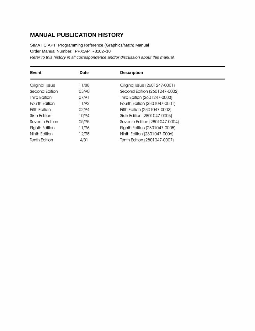
MANUAL PUBLICATION HISTORY
SIMATIC APT Programming Reference (Graphics/Math) ManualOrder Manual Number: PPX:APT--8102--10Refer to this history in all correspondence and/or discussion about this manual.
Event Date Description
Original Issue 11/88 Original Issue (2601247-0001)Second Edition 03/90 Second Edition (2601247-0002)Third Edition 07/91 Third Edition (2601247-0003)Fourth Edition 11/92 Fourth Edition (2801047-0001)Fifth Edition 02/94 Fifth Edition (2801047-0002)Sixth Edition 10/94 Sixth Edition (2801047-0003)Seventh Edition 05/95 Seventh Edition (2801047-0004)Eighth Edition 11/96 Eighth Edition (2801047-0005)Ninth Edition 12/98 Ninth Edition (2801047-0006)Tenth Edition 4/01 Tenth Edition (2801047-0007)
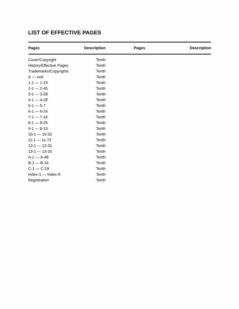
LIST OF EFFECTIVE PAGES
Pages Description Pages Description
Cover/Copyright TenthHistory/Effective Pages TenthTrademarks/Copyrights Tenthiii — xxiii Tenth1-1 — 1-10 Tenth2-1 — 2-45 Tenth3-1 — 3-28 Tenth4-1 — 4-28 Tenth5-1 — 5-7 Tenth6-1 — 6-24 Tenth7-1 — 7-16 Tenth8-1 — 8-25 Tenth9-1 — 9-15 Tenth10-1 — 10-32 Tenth11-1 — 11-72 Tenth12-1 — 12-31 Tenth13-1 — 13-20 TenthA-1 — A-48 TenthB-1 — B-16 TenthC-1 — C-19 TenthIndex-1 — Index-9 TenthRegistration Tenth

Trademarks and Copyrights
S5t is a trademark, and STEPr, SIMATICr, and SINECr are registered trademarks, of Siemens AG.
PCSt, 386/ATMt, APTt, Series 500t, Series 505t, TISOFTt, TISTARt, TIWAYt, Thermocouplet, and UNILINKt aretrademarks of Siemens Energy & Automation, Inc.
Motorolar is a registered trademark of Motorola, Incorporated.
Windowsr, Windowsr95, Windows NTr, Windowsr2000, Microsoftr, andMS-DOSrare registered trademarks of Microsoft Corporation.
UNIXr is a registered trademark of Novell, Inc.


Contents iii
Contents
Preface xxiii. . . . . . . . . . . . . . . . . . . . . . . . . . . . . . . . . . . . . . . . . . . . . . . . . . . . . . . . . . . . . . . . .Chapter 1 Continuous Function Charts 1-1. . . . . . . . . . . . . . . . . . . . . . . . . . . . . . . . . .1.1 Understanding Continuous Function Charts 1-2. . . . . . . . . . . . . . . . . . . . . . . . . . . . . . . . . . . . . .
Continuous Function Chart Language 1-2. . . . . . . . . . . . . . . . . . . . . . . . . . . . . . . . . . . . . . . . . . . . . .CFC Scope and Operation 1-3. . . . . . . . . . . . . . . . . . . . . . . . . . . . . . . . . . . . . . . . . . . . . . . . . . . . . . . .
1.2 Continuous Function Blocks 1-4. . . . . . . . . . . . . . . . . . . . . . . . . . . . . . . . . . . . . . . . . . . . . . . . . . . .Categories 1-4. . . . . . . . . . . . . . . . . . . . . . . . . . . . . . . . . . . . . . . . . . . . . . . . . . . . . . . . . . . . . . . . . . . . .Availability 1-4. . . . . . . . . . . . . . . . . . . . . . . . . . . . . . . . . . . . . . . . . . . . . . . . . . . . . . . . . . . . . . . . . . . . . .Configuring CFBs 1-6. . . . . . . . . . . . . . . . . . . . . . . . . . . . . . . . . . . . . . . . . . . . . . . . . . . . . . . . . . . . . . .Commands 1-8. . . . . . . . . . . . . . . . . . . . . . . . . . . . . . . . . . . . . . . . . . . . . . . . . . . . . . . . . . . . . . . . . . . . .Extensions 1-9. . . . . . . . . . . . . . . . . . . . . . . . . . . . . . . . . . . . . . . . . . . . . . . . . . . . . . . . . . . . . . . . . . . . .Error-Code Extensions 1-10. . . . . . . . . . . . . . . . . . . . . . . . . . . . . . . . . . . . . . . . . . . . . . . . . . . . . . . . . . .
Chapter 2 Standard Control Blocks 2-1. . . . . . . . . . . . . . . . . . . . . . . . . . . . . . . . . . . . .2.1 Understanding Standard Control Blocks 2-2. . . . . . . . . . . . . . . . . . . . . . . . . . . . . . . . . . . . . . . . .
Overview 2-2. . . . . . . . . . . . . . . . . . . . . . . . . . . . . . . . . . . . . . . . . . . . . . . . . . . . . . . . . . . . . . . . . . . . . . .Availability 2-2. . . . . . . . . . . . . . . . . . . . . . . . . . . . . . . . . . . . . . . . . . . . . . . . . . . . . . . . . . . . . . . . . . . . . .Loop Control 2-2. . . . . . . . . . . . . . . . . . . . . . . . . . . . . . . . . . . . . . . . . . . . . . . . . . . . . . . . . . . . . . . . . . . .
2.2 PID Blocks 2-3. . . . . . . . . . . . . . . . . . . . . . . . . . . . . . . . . . . . . . . . . . . . . . . . . . . . . . . . . . . . . . . . . . . . .Overview 2-3. . . . . . . . . . . . . . . . . . . . . . . . . . . . . . . . . . . . . . . . . . . . . . . . . . . . . . . . . . . . . . . . . . . . . . .Availability 2-3. . . . . . . . . . . . . . . . . . . . . . . . . . . . . . . . . . . . . . . . . . . . . . . . . . . . . . . . . . . . . . . . . . . . . .Standard PID Algorithm (Position Algorithm) 2-4. . . . . . . . . . . . . . . . . . . . . . . . . . . . . . . . . . . . . . . .Velocity Algorithm 2-4. . . . . . . . . . . . . . . . . . . . . . . . . . . . . . . . . . . . . . . . . . . . . . . . . . . . . . . . . . . . . . .PID Loop CFB and Form 2-5. . . . . . . . . . . . . . . . . . . . . . . . . . . . . . . . . . . . . . . . . . . . . . . . . . . . . . . . .Process Variable Information 2-9. . . . . . . . . . . . . . . . . . . . . . . . . . . . . . . . . . . . . . . . . . . . . . . . . . . . . .Process Setpoint Information 2-11. . . . . . . . . . . . . . . . . . . . . . . . . . . . . . . . . . . . . . . . . . . . . . . . . . . . . .Output Information 2-13. . . . . . . . . . . . . . . . . . . . . . . . . . . . . . . . . . . . . . . . . . . . . . . . . . . . . . . . . . . . . . .Controller Options 2-15. . . . . . . . . . . . . . . . . . . . . . . . . . . . . . . . . . . . . . . . . . . . . . . . . . . . . . . . . . . . . . .Error Algorithm 2-15. . . . . . . . . . . . . . . . . . . . . . . . . . . . . . . . . . . . . . . . . . . . . . . . . . . . . . . . . . . . . . . . . .Direct/Reverse Acting Control 2-15. . . . . . . . . . . . . . . . . . . . . . . . . . . . . . . . . . . . . . . . . . . . . . . . . . . . .Freeze Bias 2-16. . . . . . . . . . . . . . . . . . . . . . . . . . . . . . . . . . . . . . . . . . . . . . . . . . . . . . . . . . . . . . . . . . . .Associated Math 2-17. . . . . . . . . . . . . . . . . . . . . . . . . . . . . . . . . . . . . . . . . . . . . . . . . . . . . . . . . . . . . . . .Tuning Parameters 2-19. . . . . . . . . . . . . . . . . . . . . . . . . . . . . . . . . . . . . . . . . . . . . . . . . . . . . . . . . . . . . .PID Commands and Flags 2-21. . . . . . . . . . . . . . . . . . . . . . . . . . . . . . . . . . . . . . . . . . . . . . . . . . . . . . . .Loops in Manual Mode 2-22. . . . . . . . . . . . . . . . . . . . . . . . . . . . . . . . . . . . . . . . . . . . . . . . . . . . . . . . . . .Loops in Automatic Mode 2-22. . . . . . . . . . . . . . . . . . . . . . . . . . . . . . . . . . . . . . . . . . . . . . . . . . . . . . . . .Loops in Cascade Mode 2-22. . . . . . . . . . . . . . . . . . . . . . . . . . . . . . . . . . . . . . . . . . . . . . . . . . . . . . . . . .PID Extensions 2-23. . . . . . . . . . . . . . . . . . . . . . . . . . . . . . . . . . . . . . . . . . . . . . . . . . . . . . . . . . . . . . . . .Availability 2-23. . . . . . . . . . . . . . . . . . . . . . . . . . . . . . . . . . . . . . . . . . . . . . . . . . . . . . . . . . . . . . . . . . . . . .PID V-Flag and C-Flag Extension Variables 2-25. . . . . . . . . . . . . . . . . . . . . . . . . . . . . . . . . . . . . . . . .Loop Status Extensions 2-27. . . . . . . . . . . . . . . . . . . . . . . . . . . . . . . . . . . . . . . . . . . . . . . . . . . . . . . . . .Reset Windup Protection and the .AWS Extension 2-28. . . . . . . . . . . . . . . . . . . . . . . . . . . . . . . . . . .Map Tuning and Alarm Data to 505 S-Memory 2-29. . . . . . . . . . . . . . . . . . . . . . . . . . . . . . . . . . . . . . .RTD and Thermocouple Module Extensions for Series 505 2-31. . . . . . . . . . . . . . . . . . . . . . . . . . . .
iv Contents
2.3 On/Off Block 2-32. . . . . . . . . . . . . . . . . . . . . . . . . . . . . . . . . . . . . . . . . . . . . . . . . . . . . . . . . . . . . . . . . . .Overview 2-32. . . . . . . . . . . . . . . . . . . . . . . . . . . . . . . . . . . . . . . . . . . . . . . . . . . . . . . . . . . . . . . . . . . . . . .Availability 2-32. . . . . . . . . . . . . . . . . . . . . . . . . . . . . . . . . . . . . . . . . . . . . . . . . . . . . . . . . . . . . . . . . . . . . .Block Configuration 2-32. . . . . . . . . . . . . . . . . . . . . . . . . . . . . . . . . . . . . . . . . . . . . . . . . . . . . . . . . . . . . .On/Off Commands 2-35. . . . . . . . . . . . . . . . . . . . . . . . . . . . . . . . . . . . . . . . . . . . . . . . . . . . . . . . . . . . . .On/Off Extensions 2-36. . . . . . . . . . . . . . . . . . . . . . . . . . . . . . . . . . . . . . . . . . . . . . . . . . . . . . . . . . . . . . .
2.4 Analog Alarm Block 2-38. . . . . . . . . . . . . . . . . . . . . . . . . . . . . . . . . . . . . . . . . . . . . . . . . . . . . . . . . . . .Overview 2-38. . . . . . . . . . . . . . . . . . . . . . . . . . . . . . . . . . . . . . . . . . . . . . . . . . . . . . . . . . . . . . . . . . . . . . .Availability 2-38. . . . . . . . . . . . . . . . . . . . . . . . . . . . . . . . . . . . . . . . . . . . . . . . . . . . . . . . . . . . . . . . . . . . . .Analog Alarm Commands 2-40. . . . . . . . . . . . . . . . . . . . . . . . . . . . . . . . . . . . . . . . . . . . . . . . . . . . . . . .Analog Alarm Extensions 2-40. . . . . . . . . . . . . . . . . . . . . . . . . . . . . . . . . . . . . . . . . . . . . . . . . . . . . . . . .Analog Alarm V-Flag and C-Flag Extension Variables 2-42. . . . . . . . . . . . . . . . . . . . . . . . . . . . . . . . .Associated Math 2-43. . . . . . . . . . . . . . . . . . . . . . . . . . . . . . . . . . . . . . . . . . . . . . . . . . . . . . . . . . . . . . . .S-Memory Variables (Series 505 only) 2-44. . . . . . . . . . . . . . . . . . . . . . . . . . . . . . . . . . . . . . . . . . . . . .
Chapter 3 Dynamic Control Blocks 3-1. . . . . . . . . . . . . . . . . . . . . . . . . . . . . . . . . . . . . .
3.1 Understanding Dynamic Blocks 3-2. . . . . . . . . . . . . . . . . . . . . . . . . . . . . . . . . . . . . . . . . . . . . . . . .Overview 3-2. . . . . . . . . . . . . . . . . . . . . . . . . . . . . . . . . . . . . . . . . . . . . . . . . . . . . . . . . . . . . . . . . . . . . . .Availability 3-2. . . . . . . . . . . . . . . . . . . . . . . . . . . . . . . . . . . . . . . . . . . . . . . . . . . . . . . . . . . . . . . . . . . . . .Enabling and Disabling Blocks 3-3. . . . . . . . . . . . . . . . . . . . . . . . . . . . . . . . . . . . . . . . . . . . . . . . . . . .Initialization 3-4. . . . . . . . . . . . . . . . . . . . . . . . . . . . . . . . . . . . . . . . . . . . . . . . . . . . . . . . . . . . . . . . . . . . .Simulation Equations 3-6. . . . . . . . . . . . . . . . . . . . . . . . . . . . . . . . . . . . . . . . . . . . . . . . . . . . . . . . . . . .
3.2 Second Order Lead Lag 3-7. . . . . . . . . . . . . . . . . . . . . . . . . . . . . . . . . . . . . . . . . . . . . . . . . . . . . . . . .Overview 3-7. . . . . . . . . . . . . . . . . . . . . . . . . . . . . . . . . . . . . . . . . . . . . . . . . . . . . . . . . . . . . . . . . . . . . . .Availability 3-7. . . . . . . . . . . . . . . . . . . . . . . . . . . . . . . . . . . . . . . . . . . . . . . . . . . . . . . . . . . . . . . . . . . . . .Block Configuration 3-8. . . . . . . . . . . . . . . . . . . . . . . . . . . . . . . . . . . . . . . . . . . . . . . . . . . . . . . . . . . . . .Commands and Extensions 3-9. . . . . . . . . . . . . . . . . . . . . . . . . . . . . . . . . . . . . . . . . . . . . . . . . . . . . . .
3.3 Second Order Lag 3-10. . . . . . . . . . . . . . . . . . . . . . . . . . . . . . . . . . . . . . . . . . . . . . . . . . . . . . . . . . . . . .Overview 3-10. . . . . . . . . . . . . . . . . . . . . . . . . . . . . . . . . . . . . . . . . . . . . . . . . . . . . . . . . . . . . . . . . . . . . . .Availability 3-10. . . . . . . . . . . . . . . . . . . . . . . . . . . . . . . . . . . . . . . . . . . . . . . . . . . . . . . . . . . . . . . . . . . . . .Block Configuration 3-11. . . . . . . . . . . . . . . . . . . . . . . . . . . . . . . . . . . . . . . . . . . . . . . . . . . . . . . . . . . . . .Commands and Extensions 3-12. . . . . . . . . . . . . . . . . . . . . . . . . . . . . . . . . . . . . . . . . . . . . . . . . . . . . . .
3.4 First Order Lead Lag 3-13. . . . . . . . . . . . . . . . . . . . . . . . . . . . . . . . . . . . . . . . . . . . . . . . . . . . . . . . . . .Overview 3-13. . . . . . . . . . . . . . . . . . . . . . . . . . . . . . . . . . . . . . . . . . . . . . . . . . . . . . . . . . . . . . . . . . . . . . .Availability 3-14. . . . . . . . . . . . . . . . . . . . . . . . . . . . . . . . . . . . . . . . . . . . . . . . . . . . . . . . . . . . . . . . . . . . . .Block Configuration 3-15. . . . . . . . . . . . . . . . . . . . . . . . . . . . . . . . . . . . . . . . . . . . . . . . . . . . . . . . . . . . . .Commands and Extensions 3-16. . . . . . . . . . . . . . . . . . . . . . . . . . . . . . . . . . . . . . . . . . . . . . . . . . . . . . .
3.5 First Order Lag 3-17. . . . . . . . . . . . . . . . . . . . . . . . . . . . . . . . . . . . . . . . . . . . . . . . . . . . . . . . . . . . . . . . .Overview 3-17. . . . . . . . . . . . . . . . . . . . . . . . . . . . . . . . . . . . . . . . . . . . . . . . . . . . . . . . . . . . . . . . . . . . . . .Availability 3-17. . . . . . . . . . . . . . . . . . . . . . . . . . . . . . . . . . . . . . . . . . . . . . . . . . . . . . . . . . . . . . . . . . . . . .Block Configuration 3-18. . . . . . . . . . . . . . . . . . . . . . . . . . . . . . . . . . . . . . . . . . . . . . . . . . . . . . . . . . . . . .Commands and Extensions 3-19. . . . . . . . . . . . . . . . . . . . . . . . . . . . . . . . . . . . . . . . . . . . . . . . . . . . . . .
Contents v
3.6 Derivative 3-20. . . . . . . . . . . . . . . . . . . . . . . . . . . . . . . . . . . . . . . . . . . . . . . . . . . . . . . . . . . . . . . . . . . . .Overview 3-20. . . . . . . . . . . . . . . . . . . . . . . . . . . . . . . . . . . . . . . . . . . . . . . . . . . . . . . . . . . . . . . . . . . . . . .Availability 3-20. . . . . . . . . . . . . . . . . . . . . . . . . . . . . . . . . . . . . . . . . . . . . . . . . . . . . . . . . . . . . . . . . . . . . .Block Configuration 3-21. . . . . . . . . . . . . . . . . . . . . . . . . . . . . . . . . . . . . . . . . . . . . . . . . . . . . . . . . . . . . .Commands and Extensions 3-22. . . . . . . . . . . . . . . . . . . . . . . . . . . . . . . . . . . . . . . . . . . . . . . . . . . . . . .
3.7 Dead Time Delay 3-23. . . . . . . . . . . . . . . . . . . . . . . . . . . . . . . . . . . . . . . . . . . . . . . . . . . . . . . . . . . . . . .Overview 3-23. . . . . . . . . . . . . . . . . . . . . . . . . . . . . . . . . . . . . . . . . . . . . . . . . . . . . . . . . . . . . . . . . . . . . . .Availability 3-23. . . . . . . . . . . . . . . . . . . . . . . . . . . . . . . . . . . . . . . . . . . . . . . . . . . . . . . . . . . . . . . . . . . . . .Block Configuration 3-24. . . . . . . . . . . . . . . . . . . . . . . . . . . . . . . . . . . . . . . . . . . . . . . . . . . . . . . . . . . . . .Commands and Extensions 3-25. . . . . . . . . . . . . . . . . . . . . . . . . . . . . . . . . . . . . . . . . . . . . . . . . . . . . . .
3.8 Integrator 3-26. . . . . . . . . . . . . . . . . . . . . . . . . . . . . . . . . . . . . . . . . . . . . . . . . . . . . . . . . . . . . . . . . . . . . .Overview 3-26. . . . . . . . . . . . . . . . . . . . . . . . . . . . . . . . . . . . . . . . . . . . . . . . . . . . . . . . . . . . . . . . . . . . . . .Availability 3-26. . . . . . . . . . . . . . . . . . . . . . . . . . . . . . . . . . . . . . . . . . . . . . . . . . . . . . . . . . . . . . . . . . . . . .Block Configuration 3-27. . . . . . . . . . . . . . . . . . . . . . . . . . . . . . . . . . . . . . . . . . . . . . . . . . . . . . . . . . . . . .Commands and Extensions 3-28. . . . . . . . . . . . . . . . . . . . . . . . . . . . . . . . . . . . . . . . . . . . . . . . . . . . . . .
Chapter 4 Advanced Control Blocks 4-1. . . . . . . . . . . . . . . . . . . . . . . . . . . . . . . . . . . .
4.1 Understanding Advanced Control Blocks 4-2. . . . . . . . . . . . . . . . . . . . . . . . . . . . . . . . . . . . . . . .Overview 4-2. . . . . . . . . . . . . . . . . . . . . . . . . . . . . . . . . . . . . . . . . . . . . . . . . . . . . . . . . . . . . . . . . . . . . . .Availability 4-2. . . . . . . . . . . . . . . . . . . . . . . . . . . . . . . . . . . . . . . . . . . . . . . . . . . . . . . . . . . . . . . . . . . . . .PID Functions 4-2. . . . . . . . . . . . . . . . . . . . . . . . . . . . . . . . . . . . . . . . . . . . . . . . . . . . . . . . . . . . . . . . . .Dynamic Functions 4-2. . . . . . . . . . . . . . . . . . . . . . . . . . . . . . . . . . . . . . . . . . . . . . . . . . . . . . . . . . . . . .
4.2 Dead Time Compensator 4-3. . . . . . . . . . . . . . . . . . . . . . . . . . . . . . . . . . . . . . . . . . . . . . . . . . . . . . . .Overview 4-3. . . . . . . . . . . . . . . . . . . . . . . . . . . . . . . . . . . . . . . . . . . . . . . . . . . . . . . . . . . . . . . . . . . . . . .Availability 4-3. . . . . . . . . . . . . . . . . . . . . . . . . . . . . . . . . . . . . . . . . . . . . . . . . . . . . . . . . . . . . . . . . . . . . .Block Configuration 4-4. . . . . . . . . . . . . . . . . . . . . . . . . . . . . . . . . . . . . . . . . . . . . . . . . . . . . . . . . . . . . .Commands and Extensions 4-6. . . . . . . . . . . . . . . . . . . . . . . . . . . . . . . . . . . . . . . . . . . . . . . . . . . . . . .
4.3 Dual Mode 4-8. . . . . . . . . . . . . . . . . . . . . . . . . . . . . . . . . . . . . . . . . . . . . . . . . . . . . . . . . . . . . . . . . . . . .Overview 4-8. . . . . . . . . . . . . . . . . . . . . . . . . . . . . . . . . . . . . . . . . . . . . . . . . . . . . . . . . . . . . . . . . . . . . . .Availability 4-9. . . . . . . . . . . . . . . . . . . . . . . . . . . . . . . . . . . . . . . . . . . . . . . . . . . . . . . . . . . . . . . . . . . . . .Enabling and Disabling Blocks 4-9. . . . . . . . . . . . . . . . . . . . . . . . . . . . . . . . . . . . . . . . . . . . . . . . . . . .Block Configuration 4-10. . . . . . . . . . . . . . . . . . . . . . . . . . . . . . . . . . . . . . . . . . . . . . . . . . . . . . . . . . . . . .Commands and Extensions 4-12. . . . . . . . . . . . . . . . . . . . . . . . . . . . . . . . . . . . . . . . . . . . . . . . . . . . . . .
4.4 Feedforward Output Adjust 4-14. . . . . . . . . . . . . . . . . . . . . . . . . . . . . . . . . . . . . . . . . . . . . . . . . . . . .Overview 4-14. . . . . . . . . . . . . . . . . . . . . . . . . . . . . . . . . . . . . . . . . . . . . . . . . . . . . . . . . . . . . . . . . . . . . . .Availability 4-14. . . . . . . . . . . . . . . . . . . . . . . . . . . . . . . . . . . . . . . . . . . . . . . . . . . . . . . . . . . . . . . . . . . . . .Block Configuration 4-15. . . . . . . . . . . . . . . . . . . . . . . . . . . . . . . . . . . . . . . . . . . . . . . . . . . . . . . . . . . . . .Commands and Extensions 4-17. . . . . . . . . . . . . . . . . . . . . . . . . . . . . . . . . . . . . . . . . . . . . . . . . . . . . . .
4.5 Feedforward Setpoint Adjust 4-20. . . . . . . . . . . . . . . . . . . . . . . . . . . . . . . . . . . . . . . . . . . . . . . . . . . .Overview 4-20. . . . . . . . . . . . . . . . . . . . . . . . . . . . . . . . . . . . . . . . . . . . . . . . . . . . . . . . . . . . . . . . . . . . . . .Availability 4-20. . . . . . . . . . . . . . . . . . . . . . . . . . . . . . . . . . . . . . . . . . . . . . . . . . . . . . . . . . . . . . . . . . . . . .Block Configuration 4-21. . . . . . . . . . . . . . . . . . . . . . . . . . . . . . . . . . . . . . . . . . . . . . . . . . . . . . . . . . . . . .Commands and Extensions 4-23. . . . . . . . . . . . . . . . . . . . . . . . . . . . . . . . . . . . . . . . . . . . . . . . . . . . . . .

vi Contents
4.6 Ratio Station 4-25. . . . . . . . . . . . . . . . . . . . . . . . . . . . . . . . . . . . . . . . . . . . . . . . . . . . . . . . . . . . . . . . . . .Overview 4-25. . . . . . . . . . . . . . . . . . . . . . . . . . . . . . . . . . . . . . . . . . . . . . . . . . . . . . . . . . . . . . . . . . . . . . .Availability 4-25. . . . . . . . . . . . . . . . . . . . . . . . . . . . . . . . . . . . . . . . . . . . . . . . . . . . . . . . . . . . . . . . . . . . . .Block Configuration 4-25. . . . . . . . . . . . . . . . . . . . . . . . . . . . . . . . . . . . . . . . . . . . . . . . . . . . . . . . . . . . . .Commands and Extensions 4-27. . . . . . . . . . . . . . . . . . . . . . . . . . . . . . . . . . . . . . . . . . . . . . . . . . . . . . .
Chapter 5 Limiter Blocks 5-1. . . . . . . . . . . . . . . . . . . . . . . . . . . . . . . . . . . . . . . . . . . . . . .
5.1 Understanding Limiter Blocks 5-2. . . . . . . . . . . . . . . . . . . . . . . . . . . . . . . . . . . . . . . . . . . . . . . . . . .Overview 5-2. . . . . . . . . . . . . . . . . . . . . . . . . . . . . . . . . . . . . . . . . . . . . . . . . . . . . . . . . . . . . . . . . . . . . . .Availability 5-2. . . . . . . . . . . . . . . . . . . . . . . . . . . . . . . . . . . . . . . . . . . . . . . . . . . . . . . . . . . . . . . . . . . . . .Inputs and Outputs 5-2. . . . . . . . . . . . . . . . . . . . . . . . . . . . . . . . . . . . . . . . . . . . . . . . . . . . . . . . . . . . . .Enabling and Disabling Blocks 5-2. . . . . . . . . . . . . . . . . . . . . . . . . . . . . . . . . . . . . . . . . . . . . . . . . . . .
5.2 Output Limiter 5-3. . . . . . . . . . . . . . . . . . . . . . . . . . . . . . . . . . . . . . . . . . . . . . . . . . . . . . . . . . . . . . . . .Overview 5-3. . . . . . . . . . . . . . . . . . . . . . . . . . . . . . . . . . . . . . . . . . . . . . . . . . . . . . . . . . . . . . . . . . . . . . .Availability 5-3. . . . . . . . . . . . . . . . . . . . . . . . . . . . . . . . . . . . . . . . . . . . . . . . . . . . . . . . . . . . . . . . . . . . . .Block Configuration 5-3. . . . . . . . . . . . . . . . . . . . . . . . . . . . . . . . . . . . . . . . . . . . . . . . . . . . . . . . . . . . . .Commands and Extensions 5-4. . . . . . . . . . . . . . . . . . . . . . . . . . . . . . . . . . . . . . . . . . . . . . . . . . . . . . .
5.3 Rate Limiter 5-5. . . . . . . . . . . . . . . . . . . . . . . . . . . . . . . . . . . . . . . . . . . . . . . . . . . . . . . . . . . . . . . . . . .Overview 5-5. . . . . . . . . . . . . . . . . . . . . . . . . . . . . . . . . . . . . . . . . . . . . . . . . . . . . . . . . . . . . . . . . . . . . . .Availability 5-5. . . . . . . . . . . . . . . . . . . . . . . . . . . . . . . . . . . . . . . . . . . . . . . . . . . . . . . . . . . . . . . . . . . . . .Block Configuration 5-6. . . . . . . . . . . . . . . . . . . . . . . . . . . . . . . . . . . . . . . . . . . . . . . . . . . . . . . . . . . . . .Commands and Extensions 5-7. . . . . . . . . . . . . . . . . . . . . . . . . . . . . . . . . . . . . . . . . . . . . . . . . . . . . . .
Chapter 6 Selector Blocks 6-1. . . . . . . . . . . . . . . . . . . . . . . . . . . . . . . . . . . . . . . . . . . . . .
6.1 Understanding Selector Blocks 6-2. . . . . . . . . . . . . . . . . . . . . . . . . . . . . . . . . . . . . . . . . . . . . . . . . .Overview 6-2. . . . . . . . . . . . . . . . . . . . . . . . . . . . . . . . . . . . . . . . . . . . . . . . . . . . . . . . . . . . . . . . . . . . . . .Availability 6-2. . . . . . . . . . . . . . . . . . . . . . . . . . . . . . . . . . . . . . . . . . . . . . . . . . . . . . . . . . . . . . . . . . . . . .Inputs and Outputs 6-3. . . . . . . . . . . . . . . . . . . . . . . . . . . . . . . . . . . . . . . . . . . . . . . . . . . . . . . . . . . . . .Enabling and Disabling Blocks 6-4. . . . . . . . . . . . . . . . . . . . . . . . . . . . . . . . . . . . . . . . . . . . . . . . . . . .
6.2 Average Selector 6-5. . . . . . . . . . . . . . . . . . . . . . . . . . . . . . . . . . . . . . . . . . . . . . . . . . . . . . . . . . . . . . .Overview 6-5. . . . . . . . . . . . . . . . . . . . . . . . . . . . . . . . . . . . . . . . . . . . . . . . . . . . . . . . . . . . . . . . . . . . . . .Availability 6-5. . . . . . . . . . . . . . . . . . . . . . . . . . . . . . . . . . . . . . . . . . . . . . . . . . . . . . . . . . . . . . . . . . . . . .Block Configuration 6-6. . . . . . . . . . . . . . . . . . . . . . . . . . . . . . . . . . . . . . . . . . . . . . . . . . . . . . . . . . . . . .Commands and Extensions 6-7. . . . . . . . . . . . . . . . . . . . . . . . . . . . . . . . . . . . . . . . . . . . . . . . . . . . . . .
6.3 High Selector 6-8. . . . . . . . . . . . . . . . . . . . . . . . . . . . . . . . . . . . . . . . . . . . . . . . . . . . . . . . . . . . . . . . . .Overview 6-8. . . . . . . . . . . . . . . . . . . . . . . . . . . . . . . . . . . . . . . . . . . . . . . . . . . . . . . . . . . . . . . . . . . . . . .Availability 6-8. . . . . . . . . . . . . . . . . . . . . . . . . . . . . . . . . . . . . . . . . . . . . . . . . . . . . . . . . . . . . . . . . . . . . .Block Configuration 6-8. . . . . . . . . . . . . . . . . . . . . . . . . . . . . . . . . . . . . . . . . . . . . . . . . . . . . . . . . . . . . .Commands and Extensions 6-10. . . . . . . . . . . . . . . . . . . . . . . . . . . . . . . . . . . . . . . . . . . . . . . . . . . . . . .
6.4 Inswitch Selector 6-11. . . . . . . . . . . . . . . . . . . . . . . . . . . . . . . . . . . . . . . . . . . . . . . . . . . . . . . . . . . . . . .Overview 6-11. . . . . . . . . . . . . . . . . . . . . . . . . . . . . . . . . . . . . . . . . . . . . . . . . . . . . . . . . . . . . . . . . . . . . . .Availability 6-11. . . . . . . . . . . . . . . . . . . . . . . . . . . . . . . . . . . . . . . . . . . . . . . . . . . . . . . . . . . . . . . . . . . . . .Block Configuration 6-12. . . . . . . . . . . . . . . . . . . . . . . . . . . . . . . . . . . . . . . . . . . . . . . . . . . . . . . . . . . . . .Commands and Extensions 6-13. . . . . . . . . . . . . . . . . . . . . . . . . . . . . . . . . . . . . . . . . . . . . . . . . . . . . . .
Contents vii
6.5 Low Selector 6-14. . . . . . . . . . . . . . . . . . . . . . . . . . . . . . . . . . . . . . . . . . . . . . . . . . . . . . . . . . . . . . . . . . .Overview 6-14. . . . . . . . . . . . . . . . . . . . . . . . . . . . . . . . . . . . . . . . . . . . . . . . . . . . . . . . . . . . . . . . . . . . . . .Availability 6-14. . . . . . . . . . . . . . . . . . . . . . . . . . . . . . . . . . . . . . . . . . . . . . . . . . . . . . . . . . . . . . . . . . . . . .Block Configuration 6-14. . . . . . . . . . . . . . . . . . . . . . . . . . . . . . . . . . . . . . . . . . . . . . . . . . . . . . . . . . . . . .Commands and Extensions 6-16. . . . . . . . . . . . . . . . . . . . . . . . . . . . . . . . . . . . . . . . . . . . . . . . . . . . . . .
6.6 Median Selector 6-17. . . . . . . . . . . . . . . . . . . . . . . . . . . . . . . . . . . . . . . . . . . . . . . . . . . . . . . . . . . . . . . .Overview 6-17. . . . . . . . . . . . . . . . . . . . . . . . . . . . . . . . . . . . . . . . . . . . . . . . . . . . . . . . . . . . . . . . . . . . . . .Availability 6-17. . . . . . . . . . . . . . . . . . . . . . . . . . . . . . . . . . . . . . . . . . . . . . . . . . . . . . . . . . . . . . . . . . . . . .Block Configuration 6-17. . . . . . . . . . . . . . . . . . . . . . . . . . . . . . . . . . . . . . . . . . . . . . . . . . . . . . . . . . . . . .Commands and Extensions 6-18. . . . . . . . . . . . . . . . . . . . . . . . . . . . . . . . . . . . . . . . . . . . . . . . . . . . . . .
6.7 Outswitch Selector 6-19. . . . . . . . . . . . . . . . . . . . . . . . . . . . . . . . . . . . . . . . . . . . . . . . . . . . . . . . . . . . .Overview 6-19. . . . . . . . . . . . . . . . . . . . . . . . . . . . . . . . . . . . . . . . . . . . . . . . . . . . . . . . . . . . . . . . . . . . . . .Availability 6-19. . . . . . . . . . . . . . . . . . . . . . . . . . . . . . . . . . . . . . . . . . . . . . . . . . . . . . . . . . . . . . . . . . . . . .Block Configuration 6-19. . . . . . . . . . . . . . . . . . . . . . . . . . . . . . . . . . . . . . . . . . . . . . . . . . . . . . . . . . . . . .Commands and Extensions 6-21. . . . . . . . . . . . . . . . . . . . . . . . . . . . . . . . . . . . . . . . . . . . . . . . . . . . . . .
6.8 Threshold Selector 6-22. . . . . . . . . . . . . . . . . . . . . . . . . . . . . . . . . . . . . . . . . . . . . . . . . . . . . . . . . . . . .Overview 6-22. . . . . . . . . . . . . . . . . . . . . . . . . . . . . . . . . . . . . . . . . . . . . . . . . . . . . . . . . . . . . . . . . . . . . . .Availability 6-22. . . . . . . . . . . . . . . . . . . . . . . . . . . . . . . . . . . . . . . . . . . . . . . . . . . . . . . . . . . . . . . . . . . . . .Block Configuration 6-23. . . . . . . . . . . . . . . . . . . . . . . . . . . . . . . . . . . . . . . . . . . . . . . . . . . . . . . . . . . . . .Commands and Extensions 6-24. . . . . . . . . . . . . . . . . . . . . . . . . . . . . . . . . . . . . . . . . . . . . . . . . . . . . . .
Chapter 7 Valve Control Blocks 7-1. . . . . . . . . . . . . . . . . . . . . . . . . . . . . . . . . . . . . . . . .
7.1 Understanding Valve Control Blocks 7-2. . . . . . . . . . . . . . . . . . . . . . . . . . . . . . . . . . . . . . . . . . . . .Overview 7-2. . . . . . . . . . . . . . . . . . . . . . . . . . . . . . . . . . . . . . . . . . . . . . . . . . . . . . . . . . . . . . . . . . . . . . .Availability 7-2. . . . . . . . . . . . . . . . . . . . . . . . . . . . . . . . . . . . . . . . . . . . . . . . . . . . . . . . . . . . . . . . . . . . . .Enabling and Disabling Blocks 7-2. . . . . . . . . . . . . . . . . . . . . . . . . . . . . . . . . . . . . . . . . . . . . . . . . . . .
7.2 Motor Position Control 7-3. . . . . . . . . . . . . . . . . . . . . . . . . . . . . . . . . . . . . . . . . . . . . . . . . . . . . . . . .Overview 7-3. . . . . . . . . . . . . . . . . . . . . . . . . . . . . . . . . . . . . . . . . . . . . . . . . . . . . . . . . . . . . . . . . . . . . . .Availability 7-3. . . . . . . . . . . . . . . . . . . . . . . . . . . . . . . . . . . . . . . . . . . . . . . . . . . . . . . . . . . . . . . . . . . . . .Block Configuration 7-4. . . . . . . . . . . . . . . . . . . . . . . . . . . . . . . . . . . . . . . . . . . . . . . . . . . . . . . . . . . . . .Commands and Extensions 7-5. . . . . . . . . . . . . . . . . . . . . . . . . . . . . . . . . . . . . . . . . . . . . . . . . . . . . . .
7.3 Proportional Time Control 7-6. . . . . . . . . . . . . . . . . . . . . . . . . . . . . . . . . . . . . . . . . . . . . . . . . . . . . .Overview 7-6. . . . . . . . . . . . . . . . . . . . . . . . . . . . . . . . . . . . . . . . . . . . . . . . . . . . . . . . . . . . . . . . . . . . . . .Availability 7-6. . . . . . . . . . . . . . . . . . . . . . . . . . . . . . . . . . . . . . . . . . . . . . . . . . . . . . . . . . . . . . . . . . . . . .Block Configuration 7-7. . . . . . . . . . . . . . . . . . . . . . . . . . . . . . . . . . . . . . . . . . . . . . . . . . . . . . . . . . . . . .Commands and Extensions 7-8. . . . . . . . . . . . . . . . . . . . . . . . . . . . . . . . . . . . . . . . . . . . . . . . . . . . . . .
7.4 Split Range 7-9. . . . . . . . . . . . . . . . . . . . . . . . . . . . . . . . . . . . . . . . . . . . . . . . . . . . . . . . . . . . . . . . . . . .Overview 7-9. . . . . . . . . . . . . . . . . . . . . . . . . . . . . . . . . . . . . . . . . . . . . . . . . . . . . . . . . . . . . . . . . . . . . . .Availability 7-10. . . . . . . . . . . . . . . . . . . . . . . . . . . . . . . . . . . . . . . . . . . . . . . . . . . . . . . . . . . . . . . . . . . . . .Block Configuration 7-10. . . . . . . . . . . . . . . . . . . . . . . . . . . . . . . . . . . . . . . . . . . . . . . . . . . . . . . . . . . . . .Commands and Extensions 7-12. . . . . . . . . . . . . . . . . . . . . . . . . . . . . . . . . . . . . . . . . . . . . . . . . . . . . . .
viii Contents
7.5 Valve Sequencer 7-13. . . . . . . . . . . . . . . . . . . . . . . . . . . . . . . . . . . . . . . . . . . . . . . . . . . . . . . . . . . . . . .Overview 7-13. . . . . . . . . . . . . . . . . . . . . . . . . . . . . . . . . . . . . . . . . . . . . . . . . . . . . . . . . . . . . . . . . . . . . . .Availability 7-13. . . . . . . . . . . . . . . . . . . . . . . . . . . . . . . . . . . . . . . . . . . . . . . . . . . . . . . . . . . . . . . . . . . . . .Block Configuration 7-14. . . . . . . . . . . . . . . . . . . . . . . . . . . . . . . . . . . . . . . . . . . . . . . . . . . . . . . . . . . . . .Commands and Extensions 7-16. . . . . . . . . . . . . . . . . . . . . . . . . . . . . . . . . . . . . . . . . . . . . . . . . . . . . . .
Chapter 8 Math Control Blocks 8-1. . . . . . . . . . . . . . . . . . . . . . . . . . . . . . . . . . . . . . . . .
8.1 Understanding Math Control Blocks 8-2. . . . . . . . . . . . . . . . . . . . . . . . . . . . . . . . . . . . . . . . . . . . .Overview 8-2. . . . . . . . . . . . . . . . . . . . . . . . . . . . . . . . . . . . . . . . . . . . . . . . . . . . . . . . . . . . . . . . . . . . . . .Availability 8-3. . . . . . . . . . . . . . . . . . . . . . . . . . . . . . . . . . . . . . . . . . . . . . . . . . . . . . . . . . . . . . . . . . . . . .Inputs and Outputs 8-4. . . . . . . . . . . . . . . . . . . . . . . . . . . . . . . . . . . . . . . . . . . . . . . . . . . . . . . . . . . . . .
8.2 Absolute Value 8-5. . . . . . . . . . . . . . . . . . . . . . . . . . . . . . . . . . . . . . . . . . . . . . . . . . . . . . . . . . . . . . . . .Overview 8-5. . . . . . . . . . . . . . . . . . . . . . . . . . . . . . . . . . . . . . . . . . . . . . . . . . . . . . . . . . . . . . . . . . . . . . .Availability 8-5. . . . . . . . . . . . . . . . . . . . . . . . . . . . . . . . . . . . . . . . . . . . . . . . . . . . . . . . . . . . . . . . . . . . . .Extensions 8-6. . . . . . . . . . . . . . . . . . . . . . . . . . . . . . . . . . . . . . . . . . . . . . . . . . . . . . . . . . . . . . . . . . . . .
8.3 Divider 8-7. . . . . . . . . . . . . . . . . . . . . . . . . . . . . . . . . . . . . . . . . . . . . . . . . . . . . . . . . . . . . . . . . . . . . . . .Overview 8-7. . . . . . . . . . . . . . . . . . . . . . . . . . . . . . . . . . . . . . . . . . . . . . . . . . . . . . . . . . . . . . . . . . . . . . .Availability 8-7. . . . . . . . . . . . . . . . . . . . . . . . . . . . . . . . . . . . . . . . . . . . . . . . . . . . . . . . . . . . . . . . . . . . . .Extensions 8-8. . . . . . . . . . . . . . . . . . . . . . . . . . . . . . . . . . . . . . . . . . . . . . . . . . . . . . . . . . . . . . . . . . . . .
8.4 Interlock 8-9. . . . . . . . . . . . . . . . . . . . . . . . . . . . . . . . . . . . . . . . . . . . . . . . . . . . . . . . . . . . . . . . . . . . . . .Overview 8-9. . . . . . . . . . . . . . . . . . . . . . . . . . . . . . . . . . . . . . . . . . . . . . . . . . . . . . . . . . . . . . . . . . . . . . .Availability 8-9. . . . . . . . . . . . . . . . . . . . . . . . . . . . . . . . . . . . . . . . . . . . . . . . . . . . . . . . . . . . . . . . . . . . . .Priorities 8-10. . . . . . . . . . . . . . . . . . . . . . . . . . . . . . . . . . . . . . . . . . . . . . . . . . . . . . . . . . . . . . . . . . . . . . .
8.5 Math 8-11. . . . . . . . . . . . . . . . . . . . . . . . . . . . . . . . . . . . . . . . . . . . . . . . . . . . . . . . . . . . . . . . . . . . . . . . . .Overview 8-11. . . . . . . . . . . . . . . . . . . . . . . . . . . . . . . . . . . . . . . . . . . . . . . . . . . . . . . . . . . . . . . . . . . . . . .Availability 8-11. . . . . . . . . . . . . . . . . . . . . . . . . . . . . . . . . . . . . . . . . . . . . . . . . . . . . . . . . . . . . . . . . . . . . .Controlling Speed of Series 505 Math Execution 8-11. . . . . . . . . . . . . . . . . . . . . . . . . . . . . . . . . . . . .Enabling and Disabling Blocks 8-14. . . . . . . . . . . . . . . . . . . . . . . . . . . . . . . . . . . . . . . . . . . . . . . . . . . .Commands and Extensions 8-15. . . . . . . . . . . . . . . . . . . . . . . . . . . . . . . . . . . . . . . . . . . . . . . . . . . . . . .
8.6 Multiplier 8-16. . . . . . . . . . . . . . . . . . . . . . . . . . . . . . . . . . . . . . . . . . . . . . . . . . . . . . . . . . . . . . . . . . . . . .Overview 8-16. . . . . . . . . . . . . . . . . . . . . . . . . . . . . . . . . . . . . . . . . . . . . . . . . . . . . . . . . . . . . . . . . . . . . . .Availability 8-16. . . . . . . . . . . . . . . . . . . . . . . . . . . . . . . . . . . . . . . . . . . . . . . . . . . . . . . . . . . . . . . . . . . . . .Extensions 8-17. . . . . . . . . . . . . . . . . . . . . . . . . . . . . . . . . . . . . . . . . . . . . . . . . . . . . . . . . . . . . . . . . . . . .
8.7 Square 8-18. . . . . . . . . . . . . . . . . . . . . . . . . . . . . . . . . . . . . . . . . . . . . . . . . . . . . . . . . . . . . . . . . . . . . . . .Overview 8-18. . . . . . . . . . . . . . . . . . . . . . . . . . . . . . . . . . . . . . . . . . . . . . . . . . . . . . . . . . . . . . . . . . . . . . .Availability 8-18. . . . . . . . . . . . . . . . . . . . . . . . . . . . . . . . . . . . . . . . . . . . . . . . . . . . . . . . . . . . . . . . . . . . . .Extensions 8-19. . . . . . . . . . . . . . . . . . . . . . . . . . . . . . . . . . . . . . . . . . . . . . . . . . . . . . . . . . . . . . . . . . . . .
8.8 Square Root 8-20. . . . . . . . . . . . . . . . . . . . . . . . . . . . . . . . . . . . . . . . . . . . . . . . . . . . . . . . . . . . . . . . . . .Overview 8-20. . . . . . . . . . . . . . . . . . . . . . . . . . . . . . . . . . . . . . . . . . . . . . . . . . . . . . . . . . . . . . . . . . . . . . .Availability 8-20. . . . . . . . . . . . . . . . . . . . . . . . . . . . . . . . . . . . . . . . . . . . . . . . . . . . . . . . . . . . . . . . . . . . . .Extensions 8-21. . . . . . . . . . . . . . . . . . . . . . . . . . . . . . . . . . . . . . . . . . . . . . . . . . . . . . . . . . . . . . . . . . . . .

Contents ix
8.9 Subtractor 8-22. . . . . . . . . . . . . . . . . . . . . . . . . . . . . . . . . . . . . . . . . . . . . . . . . . . . . . . . . . . . . . . . . . . . .Overview 8-22. . . . . . . . . . . . . . . . . . . . . . . . . . . . . . . . . . . . . . . . . . . . . . . . . . . . . . . . . . . . . . . . . . . . . . .Availability 8-22. . . . . . . . . . . . . . . . . . . . . . . . . . . . . . . . . . . . . . . . . . . . . . . . . . . . . . . . . . . . . . . . . . . . . .Extensions 8-23. . . . . . . . . . . . . . . . . . . . . . . . . . . . . . . . . . . . . . . . . . . . . . . . . . . . . . . . . . . . . . . . . . . . .
8.10 Summer 8-24. . . . . . . . . . . . . . . . . . . . . . . . . . . . . . . . . . . . . . . . . . . . . . . . . . . . . . . . . . . . . . . . . . . . . . .Overview 8-24. . . . . . . . . . . . . . . . . . . . . . . . . . . . . . . . . . . . . . . . . . . . . . . . . . . . . . . . . . . . . . . . . . . . . . .Availability 8-24. . . . . . . . . . . . . . . . . . . . . . . . . . . . . . . . . . . . . . . . . . . . . . . . . . . . . . . . . . . . . . . . . . . . . .Extensions 8-25. . . . . . . . . . . . . . . . . . . . . . . . . . . . . . . . . . . . . . . . . . . . . . . . . . . . . . . . . . . . . . . . . . . . .
Chapter 9 Other Control Blocks 9-1. . . . . . . . . . . . . . . . . . . . . . . . . . . . . . . . . . . . . . . . .
9.1 Understanding Other Control Blocks 9-2. . . . . . . . . . . . . . . . . . . . . . . . . . . . . . . . . . . . . . . . . . . .Overview 9-2. . . . . . . . . . . . . . . . . . . . . . . . . . . . . . . . . . . . . . . . . . . . . . . . . . . . . . . . . . . . . . . . . . . . . . .Availability 9-2. . . . . . . . . . . . . . . . . . . . . . . . . . . . . . . . . . . . . . . . . . . . . . . . . . . . . . . . . . . . . . . . . . . . . .Enabling and Disabling Blocks 9-2. . . . . . . . . . . . . . . . . . . . . . . . . . . . . . . . . . . . . . . . . . . . . . . . . . . .
9.2 Anti-Reset Windup Protection/Constraint Type 9-3. . . . . . . . . . . . . . . . . . . . . . . . . . . . . . . . . . .Overview 9-3. . . . . . . . . . . . . . . . . . . . . . . . . . . . . . . . . . . . . . . . . . . . . . . . . . . . . . . . . . . . . . . . . . . . . . .Availability 9-3. . . . . . . . . . . . . . . . . . . . . . . . . . . . . . . . . . . . . . . . . . . . . . . . . . . . . . . . . . . . . . . . . . . . . .Block Configuration 9-4. . . . . . . . . . . . . . . . . . . . . . . . . . . . . . . . . . . . . . . . . . . . . . . . . . . . . . . . . . . . . .Commands and Extensions 9-5. . . . . . . . . . . . . . . . . . . . . . . . . . . . . . . . . . . . . . . . . . . . . . . . . . . . . . .
9.3 Anti-Reset Windup Protection/Select Type 9-6. . . . . . . . . . . . . . . . . . . . . . . . . . . . . . . . . . . . . . .Overview 9-6. . . . . . . . . . . . . . . . . . . . . . . . . . . . . . . . . . . . . . . . . . . . . . . . . . . . . . . . . . . . . . . . . . . . . . .Availability 9-6. . . . . . . . . . . . . . . . . . . . . . . . . . . . . . . . . . . . . . . . . . . . . . . . . . . . . . . . . . . . . . . . . . . . . .Block Configuration 9-7. . . . . . . . . . . . . . . . . . . . . . . . . . . . . . . . . . . . . . . . . . . . . . . . . . . . . . . . . . . . . .Commands and Extensions 9-8. . . . . . . . . . . . . . . . . . . . . . . . . . . . . . . . . . . . . . . . . . . . . . . . . . . . . . .
9.4 Correlated Lookup Table 9-9. . . . . . . . . . . . . . . . . . . . . . . . . . . . . . . . . . . . . . . . . . . . . . . . . . . . . . . .Overview 9-9. . . . . . . . . . . . . . . . . . . . . . . . . . . . . . . . . . . . . . . . . . . . . . . . . . . . . . . . . . . . . . . . . . . . . . .Availability 9-9. . . . . . . . . . . . . . . . . . . . . . . . . . . . . . . . . . . . . . . . . . . . . . . . . . . . . . . . . . . . . . . . . . . . . .Block Configuration 9-9. . . . . . . . . . . . . . . . . . . . . . . . . . . . . . . . . . . . . . . . . . . . . . . . . . . . . . . . . . . . . .Commands and Extensions 9-12. . . . . . . . . . . . . . . . . . . . . . . . . . . . . . . . . . . . . . . . . . . . . . . . . . . . . . .
9.5 Scale 9-13. . . . . . . . . . . . . . . . . . . . . . . . . . . . . . . . . . . . . . . . . . . . . . . . . . . . . . . . . . . . . . . . . . . . . . . . . .Overview 9-13. . . . . . . . . . . . . . . . . . . . . . . . . . . . . . . . . . . . . . . . . . . . . . . . . . . . . . . . . . . . . . . . . . . . . . .Availability 9-13. . . . . . . . . . . . . . . . . . . . . . . . . . . . . . . . . . . . . . . . . . . . . . . . . . . . . . . . . . . . . . . . . . . . . .Block Configuration 9-13. . . . . . . . . . . . . . . . . . . . . . . . . . . . . . . . . . . . . . . . . . . . . . . . . . . . . . . . . . . . . .Commands and Extensions 9-15. . . . . . . . . . . . . . . . . . . . . . . . . . . . . . . . . . . . . . . . . . . . . . . . . . . . . . .
Chapter 10 Math Language Overview 10-1. . . . . . . . . . . . . . . . . . . . . . . . . . . . . . . . . . .
10.1 Understanding the Math Language 10-2. . . . . . . . . . . . . . . . . . . . . . . . . . . . . . . . . . . . . . . . . . . . . .Math Blocks 10-2. . . . . . . . . . . . . . . . . . . . . . . . . . . . . . . . . . . . . . . . . . . . . . . . . . . . . . . . . . . . . . . . . . . .Types of Math Block Code 10-4. . . . . . . . . . . . . . . . . . . . . . . . . . . . . . . . . . . . . . . . . . . . . . . . . . . . . . . .Guidelines for Series 505 Controllers 10-5. . . . . . . . . . . . . . . . . . . . . . . . . . . . . . . . . . . . . . . . . . . . . . .Key Words Used by APT 10-6. . . . . . . . . . . . . . . . . . . . . . . . . . . . . . . . . . . . . . . . . . . . . . . . . . . . . . . . .

x Contents
10.2 Identifiers 10-7. . . . . . . . . . . . . . . . . . . . . . . . . . . . . . . . . . . . . . . . . . . . . . . . . . . . . . . . . . . . . . . . . . . . .Overview 10-7. . . . . . . . . . . . . . . . . . . . . . . . . . . . . . . . . . . . . . . . . . . . . . . . . . . . . . . . . . . . . . . . . . . . . . .User-defined Identifiers 10-7. . . . . . . . . . . . . . . . . . . . . . . . . . . . . . . . . . . . . . . . . . . . . . . . . . . . . . . . . .System-defined Extensions 10-8. . . . . . . . . . . . . . . . . . . . . . . . . . . . . . . . . . . . . . . . . . . . . . . . . . . . . . .User-defined Extensions 10-8. . . . . . . . . . . . . . . . . . . . . . . . . . . . . . . . . . . . . . . . . . . . . . . . . . . . . . . . .
10.3 Direct Memory Addressing 10-9. . . . . . . . . . . . . . . . . . . . . . . . . . . . . . . . . . . . . . . . . . . . . . . . . . . . . .Overview 10-9. . . . . . . . . . . . . . . . . . . . . . . . . . . . . . . . . . . . . . . . . . . . . . . . . . . . . . . . . . . . . . . . . . . . . . .
10.4 Data Types and Arithmetic Operations 10-10. . . . . . . . . . . . . . . . . . . . . . . . . . . . . . . . . . . . . . . . . . .Overview 10-10. . . . . . . . . . . . . . . . . . . . . . . . . . . . . . . . . . . . . . . . . . . . . . . . . . . . . . . . . . . . . . . . . . . . . . .Expressions 10-11. . . . . . . . . . . . . . . . . . . . . . . . . . . . . . . . . . . . . . . . . . . . . . . . . . . . . . . . . . . . . . . . . . . .Integers 10-12. . . . . . . . . . . . . . . . . . . . . . . . . . . . . . . . . . . . . . . . . . . . . . . . . . . . . . . . . . . . . . . . . . . . . . . .Real Numbers 10-13. . . . . . . . . . . . . . . . . . . . . . . . . . . . . . . . . . . . . . . . . . . . . . . . . . . . . . . . . . . . . . . . . .Boolean Values 10-14. . . . . . . . . . . . . . . . . . . . . . . . . . . . . . . . . . . . . . . . . . . . . . . . . . . . . . . . . . . . . . . . .
10.5 Math Block Structure 10-16. . . . . . . . . . . . . . . . . . . . . . . . . . . . . . . . . . . . . . . . . . . . . . . . . . . . . . . . . . .Overview 10-16. . . . . . . . . . . . . . . . . . . . . . . . . . . . . . . . . . . . . . . . . . . . . . . . . . . . . . . . . . . . . . . . . . . . . . .Code Specifier Section (Series 505 only) 10-18. . . . . . . . . . . . . . . . . . . . . . . . . . . . . . . . . . . . . . . . . . .Declaration Section 10-19. . . . . . . . . . . . . . . . . . . . . . . . . . . . . . . . . . . . . . . . . . . . . . . . . . . . . . . . . . . . . .Using a Declaration Statement 10-20. . . . . . . . . . . . . . . . . . . . . . . . . . . . . . . . . . . . . . . . . . . . . . . . . . . .Formatting a Declaration Statement 10-20. . . . . . . . . . . . . . . . . . . . . . . . . . . . . . . . . . . . . . . . . . . . . . . .Using a Locally-Declared Variable 10-22. . . . . . . . . . . . . . . . . . . . . . . . . . . . . . . . . . . . . . . . . . . . . . . . .Executable Section 10-23. . . . . . . . . . . . . . . . . . . . . . . . . . . . . . . . . . . . . . . . . . . . . . . . . . . . . . . . . . . . . .
10.6 Statements 10-24. . . . . . . . . . . . . . . . . . . . . . . . . . . . . . . . . . . . . . . . . . . . . . . . . . . . . . . . . . . . . . . . . . . .Overview 10-24. . . . . . . . . . . . . . . . . . . . . . . . . . . . . . . . . . . . . . . . . . . . . . . . . . . . . . . . . . . . . . . . . . . . . . .Comments 10-24. . . . . . . . . . . . . . . . . . . . . . . . . . . . . . . . . . . . . . . . . . . . . . . . . . . . . . . . . . . . . . . . . . . . .Assignment Statement 10-25. . . . . . . . . . . . . . . . . . . . . . . . . . . . . . . . . . . . . . . . . . . . . . . . . . . . . . . . . . .Procedure Statement 10-26. . . . . . . . . . . . . . . . . . . . . . . . . . . . . . . . . . . . . . . . . . . . . . . . . . . . . . . . . . . .Function Statement 10-26. . . . . . . . . . . . . . . . . . . . . . . . . . . . . . . . . . . . . . . . . . . . . . . . . . . . . . . . . . . . . .Command Statement 10-26. . . . . . . . . . . . . . . . . . . . . . . . . . . . . . . . . . . . . . . . . . . . . . . . . . . . . . . . . . . .Print Statement (Series 505 only) 10-26. . . . . . . . . . . . . . . . . . . . . . . . . . . . . . . . . . . . . . . . . . . . . . . . . .IF Statement 10-28. . . . . . . . . . . . . . . . . . . . . . . . . . . . . . . . . . . . . . . . . . . . . . . . . . . . . . . . . . . . . . . . . . . .WHILE Statement 10-30. . . . . . . . . . . . . . . . . . . . . . . . . . . . . . . . . . . . . . . . . . . . . . . . . . . . . . . . . . . . . . .Safety Guidelines for WHILE Loops 10-31. . . . . . . . . . . . . . . . . . . . . . . . . . . . . . . . . . . . . . . . . . . . . . . .Special SFC Considerations 10-31. . . . . . . . . . . . . . . . . . . . . . . . . . . . . . . . . . . . . . . . . . . . . . . . . . . . . .Special CFB Considerations 10-32. . . . . . . . . . . . . . . . . . . . . . . . . . . . . . . . . . . . . . . . . . . . . . . . . . . . . .
Chapter 11 Math Functions and Procedures 11-1. . . . . . . . . . . . . . . . . . . . . . . . . . .
11.1 Overview 11-3. . . . . . . . . . . . . . . . . . . . . . . . . . . . . . . . . . . . . . . . . . . . . . . . . . . . . . . . . . . . . . . . . . . . . .Understanding Procedures 11-3. . . . . . . . . . . . . . . . . . . . . . . . . . . . . . . . . . . . . . . . . . . . . . . . . . . . . . .Understanding Functions 11-3. . . . . . . . . . . . . . . . . . . . . . . . . . . . . . . . . . . . . . . . . . . . . . . . . . . . . . . . .Availability 11-3. . . . . . . . . . . . . . . . . . . . . . . . . . . . . . . . . . . . . . . . . . . . . . . . . . . . . . . . . . . . . . . . . . . . . .Using Functions and Procedures in Subroutines (Series 505) 11-6. . . . . . . . . . . . . . . . . . . . . . . . . .

Contents xi
11.2 Function and Procedure Definitions 11-7. . . . . . . . . . . . . . . . . . . . . . . . . . . . . . . . . . . . . . . . . . . . .ABS Function 11-7. . . . . . . . . . . . . . . . . . . . . . . . . . . . . . . . . . . . . . . . . . . . . . . . . . . . . . . . . . . . . . . . . . .ARCCOS Function 11-8. . . . . . . . . . . . . . . . . . . . . . . . . . . . . . . . . . . . . . . . . . . . . . . . . . . . . . . . . . . . . .ARCSIN Function 11-9. . . . . . . . . . . . . . . . . . . . . . . . . . . . . . . . . . . . . . . . . . . . . . . . . . . . . . . . . . . . . . .ARCTAN Function 11-10. . . . . . . . . . . . . . . . . . . . . . . . . . . . . . . . . . . . . . . . . . . . . . . . . . . . . . . . . . . . . . .BCDBIN Procedure 11-11. . . . . . . . . . . . . . . . . . . . . . . . . . . . . . . . . . . . . . . . . . . . . . . . . . . . . . . . . . . . . .BINBCD Procedure 11-12. . . . . . . . . . . . . . . . . . . . . . . . . . . . . . . . . . . . . . . . . . . . . . . . . . . . . . . . . . . . . .BIT_ASSIGN Procedure 11-13. . . . . . . . . . . . . . . . . . . . . . . . . . . . . . . . . . . . . . . . . . . . . . . . . . . . . . . . . .BITCLEAR Procedure 11-14. . . . . . . . . . . . . . . . . . . . . . . . . . . . . . . . . . . . . . . . . . . . . . . . . . . . . . . . . . . .BITSET Procedure 11-15. . . . . . . . . . . . . . . . . . . . . . . . . . . . . . . . . . . . . . . . . . . . . . . . . . . . . . . . . . . . . .BITS_TO_INT Function 11-16. . . . . . . . . . . . . . . . . . . . . . . . . . . . . . . . . . . . . . . . . . . . . . . . . . . . . . . . . .BITTEST Function 11-18. . . . . . . . . . . . . . . . . . . . . . . . . . . . . . . . . . . . . . . . . . . . . . . . . . . . . . . . . . . . . . .CLEAR Procedure 11-19. . . . . . . . . . . . . . . . . . . . . . . . . . . . . . . . . . . . . . . . . . . . . . . . . . . . . . . . . . . . . . .COPY_BYTES Procedure 11-20. . . . . . . . . . . . . . . . . . . . . . . . . . . . . . . . . . . . . . . . . . . . . . . . . . . . . . . .COPY_DIRECT Procedure 11-22. . . . . . . . . . . . . . . . . . . . . . . . . . . . . . . . . . . . . . . . . . . . . . . . . . . . . . .COS Function 11-24. . . . . . . . . . . . . . . . . . . . . . . . . . . . . . . . . . . . . . . . . . . . . . . . . . . . . . . . . . . . . . . . . .EDGE Function 11-25. . . . . . . . . . . . . . . . . . . . . . . . . . . . . . . . . . . . . . . . . . . . . . . . . . . . . . . . . . . . . . . . .EXP Function 11-26. . . . . . . . . . . . . . . . . . . . . . . . . . . . . . . . . . . . . . . . . . . . . . . . . . . . . . . . . . . . . . . . . . .FRS Procedure 11-27. . . . . . . . . . . . . . . . . . . . . . . . . . . . . . . . . . . . . . . . . . . . . . . . . . . . . . . . . . . . . . . . .FRAC Function 11-28. . . . . . . . . . . . . . . . . . . . . . . . . . . . . . . . . . . . . . . . . . . . . . . . . . . . . . . . . . . . . . . . .INTERPOLATE Procedure 11-30. . . . . . . . . . . . . . . . . . . . . . . . . . . . . . . . . . . . . . . . . . . . . . . . . . . . . . . .INT_TO_BITS Procedure 11-32. . . . . . . . . . . . . . . . . . . . . . . . . . . . . . . . . . . . . . . . . . . . . . . . . . . . . . . . .INT_TO_REAL Function 11-34. . . . . . . . . . . . . . . . . . . . . . . . . . . . . . . . . . . . . . . . . . . . . . . . . . . . . . . . .IREAD Procedure 11-35. . . . . . . . . . . . . . . . . . . . . . . . . . . . . . . . . . . . . . . . . . . . . . . . . . . . . . . . . . . . . . .IWRITE Procedure 11-36. . . . . . . . . . . . . . . . . . . . . . . . . . . . . . . . . . . . . . . . . . . . . . . . . . . . . . . . . . . . . .LATCH Procedure 11-37. . . . . . . . . . . . . . . . . . . . . . . . . . . . . . . . . . . . . . . . . . . . . . . . . . . . . . . . . . . . . . .LEAD_LAG Procedure 11-38. . . . . . . . . . . . . . . . . . . . . . . . . . . . . . . . . . . . . . . . . . . . . . . . . . . . . . . . . . .LEFTSHIFT Function 11-40. . . . . . . . . . . . . . . . . . . . . . . . . . . . . . . . . . . . . . . . . . . . . . . . . . . . . . . . . . . .LIMIT Procedure 11-41. . . . . . . . . . . . . . . . . . . . . . . . . . . . . . . . . . . . . . . . . . . . . . . . . . . . . . . . . . . . . . . .LOAD_ARRAY Procedure 11-42. . . . . . . . . . . . . . . . . . . . . . . . . . . . . . . . . . . . . . . . . . . . . . . . . . . . . . . .LOOKUP_TABLE Procedure 11-44. . . . . . . . . . . . . . . . . . . . . . . . . . . . . . . . . . . . . . . . . . . . . . . . . . . . . .LN Function 11-46. . . . . . . . . . . . . . . . . . . . . . . . . . . . . . . . . . . . . . . . . . . . . . . . . . . . . . . . . . . . . . . . . . . .LOG Function 11-47. . . . . . . . . . . . . . . . . . . . . . . . . . . . . . . . . . . . . . . . . . . . . . . . . . . . . . . . . . . . . . . . . . .MAX Procedure 11-48. . . . . . . . . . . . . . . . . . . . . . . . . . . . . . . . . . . . . . . . . . . . . . . . . . . . . . . . . . . . . . . . .MIN Procedure 11-49. . . . . . . . . . . . . . . . . . . . . . . . . . . . . . . . . . . . . . . . . . . . . . . . . . . . . . . . . . . . . . . . . .MINMAX Procedure 11-50. . . . . . . . . . . . . . . . . . . . . . . . . . . . . . . . . . . . . . . . . . . . . . . . . . . . . . . . . . . . .ON Procedure 11-51. . . . . . . . . . . . . . . . . . . . . . . . . . . . . . . . . . . . . . . . . . . . . . . . . . . . . . . . . . . . . . . . . .PACK_BITS Procedure 11-52. . . . . . . . . . . . . . . . . . . . . . . . . . . . . . . . . . . . . . . . . . . . . . . . . . . . . . . . . . .PBITS_TO_INT Procedure 11-53. . . . . . . . . . . . . . . . . . . . . . . . . . . . . . . . . . . . . . . . . . . . . . . . . . . . . . .PROUND Procedure 11-54. . . . . . . . . . . . . . . . . . . . . . . . . . . . . . . . . . . . . . . . . . . . . . . . . . . . . . . . . . . . .PTRUNC Procedure 11-55. . . . . . . . . . . . . . . . . . . . . . . . . . . . . . . . . . . . . . . . . . . . . . . . . . . . . . . . . . . . .RIGHTSHIFT Function 11-56. . . . . . . . . . . . . . . . . . . . . . . . . . . . . . . . . . . . . . . . . . . . . . . . . . . . . . . . . . .ROUND Function 11-57. . . . . . . . . . . . . . . . . . . . . . . . . . . . . . . . . . . . . . . . . . . . . . . . . . . . . . . . . . . . . . .SCALE Procedure 11-58. . . . . . . . . . . . . . . . . . . . . . . . . . . . . . . . . . . . . . . . . . . . . . . . . . . . . . . . . . . . . . .Using SCALE for a Series 505 Controller 11-60. . . . . . . . . . . . . . . . . . . . . . . . . . . . . . . . . . . . . . . . . . .Using SCALE for an S5 Controller 11-60. . . . . . . . . . . . . . . . . . . . . . . . . . . . . . . . . . . . . . . . . . . . . . . . .Compensating for the Bit Shift (S5 only) 11-61. . . . . . . . . . . . . . . . . . . . . . . . . . . . . . . . . . . . . . . . . . . .SETSSI Procedure 11-62. . . . . . . . . . . . . . . . . . . . . . . . . . . . . . . . . . . . . . . . . . . . . . . . . . . . . . . . . . . . . .SIN Function 11-64. . . . . . . . . . . . . . . . . . . . . . . . . . . . . . . . . . . . . . . . . . . . . . . . . . . . . . . . . . . . . . . . . . .SQRT Function 11-65. . . . . . . . . . . . . . . . . . . . . . . . . . . . . . . . . . . . . . . . . . . . . . . . . . . . . . . . . . . . . . . . .
xii Contents
11.2 Function and Procedure Definitions (continued)TAN Function 11-66. . . . . . . . . . . . . . . . . . . . . . . . . . . . . . . . . . . . . . . . . . . . . . . . . . . . . . . . . . . . . . . . . . .TRUNC Function 11-67. . . . . . . . . . . . . . . . . . . . . . . . . . . . . . . . . . . . . . . . . . . . . . . . . . . . . . . . . . . . . . . .UNPACK_BITS Procedure 11-68. . . . . . . . . . . . . . . . . . . . . . . . . . . . . . . . . . . . . . . . . . . . . . . . . . . . . . . .UNSCALE Procedure 11-70. . . . . . . . . . . . . . . . . . . . . . . . . . . . . . . . . . . . . . . . . . . . . . . . . . . . . . . . . . . .Using UNSCALE for a Series 505 Controller 11-71. . . . . . . . . . . . . . . . . . . . . . . . . . . . . . . . . . . . . . . .Using UNSCALE for an S5 Controller 11-71. . . . . . . . . . . . . . . . . . . . . . . . . . . . . . . . . . . . . . . . . . . . . .Viewing UNSCALE Results in Debug (S5 only) 11-72. . . . . . . . . . . . . . . . . . . . . . . . . . . . . . . . . . . . . .Compensating for the Bit Shift (S5 only) 11-72. . . . . . . . . . . . . . . . . . . . . . . . . . . . . . . . . . . . . . . . . . . .
Chapter 12 Sequential Function Charts 12-1. . . . . . . . . . . . . . . . . . . . . . . . . . . . . . . .
12.1 Understanding Sequential Function Charts 12-2. . . . . . . . . . . . . . . . . . . . . . . . . . . . . . . . . . . . . . .Overview 12-2. . . . . . . . . . . . . . . . . . . . . . . . . . . . . . . . . . . . . . . . . . . . . . . . . . . . . . . . . . . . . . . . . . . . . . .Program Flow 12-3. . . . . . . . . . . . . . . . . . . . . . . . . . . . . . . . . . . . . . . . . . . . . . . . . . . . . . . . . . . . . . . . . . .SFC Scope 12-4. . . . . . . . . . . . . . . . . . . . . . . . . . . . . . . . . . . . . . . . . . . . . . . . . . . . . . . . . . . . . . . . . . . . .
12.2 Steps 12-5. . . . . . . . . . . . . . . . . . . . . . . . . . . . . . . . . . . . . . . . . . . . . . . . . . . . . . . . . . . . . . . . . . . . . . . . .Overview 12-5. . . . . . . . . . . . . . . . . . . . . . . . . . . . . . . . . . . . . . . . . . . . . . . . . . . . . . . . . . . . . . . . . . . . . . .Types 12-5. . . . . . . . . . . . . . . . . . . . . . . . . . . . . . . . . . . . . . . . . . . . . . . . . . . . . . . . . . . . . . . . . . . . . . . . . .Sections 12-6. . . . . . . . . . . . . . . . . . . . . . . . . . . . . . . . . . . . . . . . . . . . . . . . . . . . . . . . . . . . . . . . . . . . . . .
12.3 Transitions 12-8. . . . . . . . . . . . . . . . . . . . . . . . . . . . . . . . . . . . . . . . . . . . . . . . . . . . . . . . . . . . . . . . . . . .Overview 12-8. . . . . . . . . . . . . . . . . . . . . . . . . . . . . . . . . . . . . . . . . . . . . . . . . . . . . . . . . . . . . . . . . . . . . . .Evaluation 12-10. . . . . . . . . . . . . . . . . . . . . . . . . . . . . . . . . . . . . . . . . . . . . . . . . . . . . . . . . . . . . . . . . . . . . .
12.4 Step/Transition Rules 12-12. . . . . . . . . . . . . . . . . . . . . . . . . . . . . . . . . . . . . . . . . . . . . . . . . . . . . . . . . . .Initial and End Steps 12-12. . . . . . . . . . . . . . . . . . . . . . . . . . . . . . . . . . . . . . . . . . . . . . . . . . . . . . . . . . . . .Steps and Transitions 12-13. . . . . . . . . . . . . . . . . . . . . . . . . . . . . . . . . . . . . . . . . . . . . . . . . . . . . . . . . . . .
12.5 Lines, Arrows, and Graphic Connections 12-14. . . . . . . . . . . . . . . . . . . . . . . . . . . . . . . . . . . . . . . . .Lines 12-14. . . . . . . . . . . . . . . . . . . . . . . . . . . . . . . . . . . . . . . . . . . . . . . . . . . . . . . . . . . . . . . . . . . . . . . . . .Arrows 12-15. . . . . . . . . . . . . . . . . . . . . . . . . . . . . . . . . . . . . . . . . . . . . . . . . . . . . . . . . . . . . . . . . . . . . . . . .Graphic Connections 12-16. . . . . . . . . . . . . . . . . . . . . . . . . . . . . . . . . . . . . . . . . . . . . . . . . . . . . . . . . . . .
12.6 Parallel Branches 12-17. . . . . . . . . . . . . . . . . . . . . . . . . . . . . . . . . . . . . . . . . . . . . . . . . . . . . . . . . . . . . .Parallel Branching 12-17. . . . . . . . . . . . . . . . . . . . . . . . . . . . . . . . . . . . . . . . . . . . . . . . . . . . . . . . . . . . . . .Parallel Branching Rules 12-20. . . . . . . . . . . . . . . . . . . . . . . . . . . . . . . . . . . . . . . . . . . . . . . . . . . . . . . . .
12.7 Selection Branches 12-22. . . . . . . . . . . . . . . . . . . . . . . . . . . . . . . . . . . . . . . . . . . . . . . . . . . . . . . . . . . . .Selection Branching 12-22. . . . . . . . . . . . . . . . . . . . . . . . . . . . . . . . . . . . . . . . . . . . . . . . . . . . . . . . . . . . .Selection Branching Rules 12-25. . . . . . . . . . . . . . . . . . . . . . . . . . . . . . . . . . . . . . . . . . . . . . . . . . . . . . . .
12.8 Main and Subordinate SFCs 12-28. . . . . . . . . . . . . . . . . . . . . . . . . . . . . . . . . . . . . . . . . . . . . . . . . . . . .Main SFC 12-28. . . . . . . . . . . . . . . . . . . . . . . . . . . . . . . . . . . . . . . . . . . . . . . . . . . . . . . . . . . . . . . . . . . . . .Subordinate SFCs 12-29. . . . . . . . . . . . . . . . . . . . . . . . . . . . . . . . . . . . . . . . . . . . . . . . . . . . . . . . . . . . . . .
Contents xiii
Chapter 13 Safe-State SFCs 13-1. . . . . . . . . . . . . . . . . . . . . . . . . . . . . . . . . . . . . . . . . .
13.1 Overview 13-2. . . . . . . . . . . . . . . . . . . . . . . . . . . . . . . . . . . . . . . . . . . . . . . . . . . . . . . . . . . . . . . . . . . . . .Types 13-2. . . . . . . . . . . . . . . . . . . . . . . . . . . . . . . . . . . . . . . . . . . . . . . . . . . . . . . . . . . . . . . . . . . . . . . . . .Safe-State Priority 13-2. . . . . . . . . . . . . . . . . . . . . . . . . . . . . . . . . . . . . . . . . . . . . . . . . . . . . . . . . . . . . . .Safe-State SFC Operation 13-3. . . . . . . . . . . . . . . . . . . . . . . . . . . . . . . . . . . . . . . . . . . . . . . . . . . . . . . .
13.2 Safe-State Commands 13-4. . . . . . . . . . . . . . . . . . . . . . . . . . . . . . . . . . . . . . . . . . . . . . . . . . . . . . . . . .Overview 13-4. . . . . . . . . . . . . . . . . . . . . . . . . . . . . . . . . . . . . . . . . . . . . . . . . . . . . . . . . . . . . . . . . . . . . . .SSENTRY Command 13-7. . . . . . . . . . . . . . . . . . . . . . . . . . . . . . . . . . . . . . . . . . . . . . . . . . . . . . . . . . . .SSRETURN Command 13-8. . . . . . . . . . . . . . . . . . . . . . . . . . . . . . . . . . . . . . . . . . . . . . . . . . . . . . . . . .SSDEFINE Command 13-10. . . . . . . . . . . . . . . . . . . . . . . . . . . . . . . . . . . . . . . . . . . . . . . . . . . . . . . . . . .SSTRIGGER Command 13-12. . . . . . . . . . . . . . . . . . . . . . . . . . . . . . . . . . . . . . . . . . . . . . . . . . . . . . . . . .SSARM Command 13-14. . . . . . . . . . . . . . . . . . . . . . . . . . . . . . . . . . . . . . . . . . . . . . . . . . . . . . . . . . . . . .SSDISARM Command 13-15. . . . . . . . . . . . . . . . . . . . . . . . . . . . . . . . . . . . . . . . . . . . . . . . . . . . . . . . . . .SSABORT Command 13-16. . . . . . . . . . . . . . . . . . . . . . . . . . . . . . . . . . . . . . . . . . . . . . . . . . . . . . . . . . . .
13.3 Safe-State SFC Examples 13-17. . . . . . . . . . . . . . . . . . . . . . . . . . . . . . . . . . . . . . . . . . . . . . . . . . . . . . .Emergency Procedures 13-17. . . . . . . . . . . . . . . . . . . . . . . . . . . . . . . . . . . . . . . . . . . . . . . . . . . . . . . . . .Multiple Safe-State SFCs 13-19. . . . . . . . . . . . . . . . . . . . . . . . . . . . . . . . . . . . . . . . . . . . . . . . . . . . . . . . .
Appendix A Error Messages A-1. . . . . . . . . . . . . . . . . . . . . . . . . . . . . . . . . . . . . . . . . . . .
A.1 Understanding the Compile Operation A-2. . . . . . . . . . . . . . . . . . . . . . . . . . . . . . . . . . . . . . . . . . .Overview A-2. . . . . . . . . . . . . . . . . . . . . . . . . . . . . . . . . . . . . . . . . . . . . . . . . . . . . . . . . . . . . . . . . . . . . . .Compiling with Debug A-2. . . . . . . . . . . . . . . . . . . . . . . . . . . . . . . . . . . . . . . . . . . . . . . . . . . . . . . . . . . .
A.2 Successful Compile A-3. . . . . . . . . . . . . . . . . . . . . . . . . . . . . . . . . . . . . . . . . . . . . . . . . . . . . . . . . . . .Overview A-3. . . . . . . . . . . . . . . . . . . . . . . . . . . . . . . . . . . . . . . . . . . . . . . . . . . . . . . . . . . . . . . . . . . . . . .
A.3 Compile Report Messages A-4. . . . . . . . . . . . . . . . . . . . . . . . . . . . . . . . . . . . . . . . . . . . . . . . . . . . . .Overview A-4. . . . . . . . . . . . . . . . . . . . . . . . . . . . . . . . . . . . . . . . . . . . . . . . . . . . . . . . . . . . . . . . . . . . . . .Correcting Errors A-5. . . . . . . . . . . . . . . . . . . . . . . . . . . . . . . . . . . . . . . . . . . . . . . . . . . . . . . . . . . . . . . .
A.4 Translate/Download/Debug Error Messages A-40. . . . . . . . . . . . . . . . . . . . . . . . . . . . . . . . . . . . . .Overview A-40. . . . . . . . . . . . . . . . . . . . . . . . . . . . . . . . . . . . . . . . . . . . . . . . . . . . . . . . . . . . . . . . . . . . . . .
A.5 Archive/Restore Error Messages A-43. . . . . . . . . . . . . . . . . . . . . . . . . . . . . . . . . . . . . . . . . . . . . . . .Overview A-43. . . . . . . . . . . . . . . . . . . . . . . . . . . . . . . . . . . . . . . . . . . . . . . . . . . . . . . . . . . . . . . . . . . . . . .
A.6 DOS Operating System Error Messages A-48. . . . . . . . . . . . . . . . . . . . . . . . . . . . . . . . . . . . . . . . . .
Appendix B Direct Memory Addressing B-1. . . . . . . . . . . . . . . . . . . . . . . . . . . . . . . . .
B.1 Types of Direct Memory Addressing B-2. . . . . . . . . . . . . . . . . . . . . . . . . . . . . . . . . . . . . . . . . . . . .Overview B-2. . . . . . . . . . . . . . . . . . . . . . . . . . . . . . . . . . . . . . . . . . . . . . . . . . . . . . . . . . . . . . . . . . . . . . .Availability B-2. . . . . . . . . . . . . . . . . . . . . . . . . . . . . . . . . . . . . . . . . . . . . . . . . . . . . . . . . . . . . . . . . . . . . .Status Words (Series 505 only) B-2. . . . . . . . . . . . . . . . . . . . . . . . . . . . . . . . . . . . . . . . . . . . . . . . . . . .System Data Area (RS) (S5 only) B-2. . . . . . . . . . . . . . . . . . . . . . . . . . . . . . . . . . . . . . . . . . . . . . . . . .Temporary Variables (Series 505 only) B-3. . . . . . . . . . . . . . . . . . . . . . . . . . . . . . . . . . . . . . . . . . . . .Reserved Memory B-3. . . . . . . . . . . . . . . . . . . . . . . . . . . . . . . . . . . . . . . . . . . . . . . . . . . . . . . . . . . . . . .

xiv Contents
B.2 Using Direct Addresses (Series 505 Controllers) B-4. . . . . . . . . . . . . . . . . . . . . . . . . . . . . . . . . .Reserved Memory for Series 505 B-4. . . . . . . . . . . . . . . . . . . . . . . . . . . . . . . . . . . . . . . . . . . . . . . . . .Other Reserved Locations B-7. . . . . . . . . . . . . . . . . . . . . . . . . . . . . . . . . . . . . . . . . . . . . . . . . . . . . . . .Direct Addressing Guidelines for Series 505 Controllers B-10. . . . . . . . . . . . . . . . . . . . . . . . . . . . . .
B.3 Using Direct Addresses (S5 Controllers) B-11. . . . . . . . . . . . . . . . . . . . . . . . . . . . . . . . . . . . . . . . .Reserved Memory for S5 Controllers B-11. . . . . . . . . . . . . . . . . . . . . . . . . . . . . . . . . . . . . . . . . . . . . . .Direct Addressing Guidelines for S5 Controllers B-16. . . . . . . . . . . . . . . . . . . . . . . . . . . . . . . . . . . . . .
Appendix C Inline Assembly Code for S5 C-1. . . . . . . . . . . . . . . . . . . . . . . . . . . . . . . .
C.1 The IN_ASM Statement C-2. . . . . . . . . . . . . . . . . . . . . . . . . . . . . . . . . . . . . . . . . . . . . . . . . . . . . . . . .Overview C-2. . . . . . . . . . . . . . . . . . . . . . . . . . . . . . . . . . . . . . . . . . . . . . . . . . . . . . . . . . . . . . . . . . . . . . .Availability C-2. . . . . . . . . . . . . . . . . . . . . . . . . . . . . . . . . . . . . . . . . . . . . . . . . . . . . . . . . . . . . . . . . . . . . .Formatting Inline Assembly Math Statements C-4. . . . . . . . . . . . . . . . . . . . . . . . . . . . . . . . . . . . . . . .
C.2 Parameters Available for IN_ASM Statements C-5. . . . . . . . . . . . . . . . . . . . . . . . . . . . . . . . . . . . .Overview C-5. . . . . . . . . . . . . . . . . . . . . . . . . . . . . . . . . . . . . . . . . . . . . . . . . . . . . . . . . . . . . . . . . . . . . . .Direct Addresses C-5. . . . . . . . . . . . . . . . . . . . . . . . . . . . . . . . . . . . . . . . . . . . . . . . . . . . . . . . . . . . . . . .Flags and Other Bits C-5. . . . . . . . . . . . . . . . . . . . . . . . . . . . . . . . . . . . . . . . . . . . . . . . . . . . . . . . . . . . .Words and Double Words C-5. . . . . . . . . . . . . . . . . . . . . . . . . . . . . . . . . . . . . . . . . . . . . . . . . . . . . . . .APT Symbolic Names C-6. . . . . . . . . . . . . . . . . . . . . . . . . . . . . . . . . . . . . . . . . . . . . . . . . . . . . . . . . . . .Constants C-8. . . . . . . . . . . . . . . . . . . . . . . . . . . . . . . . . . . . . . . . . . . . . . . . . . . . . . . . . . . . . . . . . . . . . .
C.3 How to Incorporate Your Block C-10. . . . . . . . . . . . . . . . . . . . . . . . . . . . . . . . . . . . . . . . . . . . . . . . . .Overview C-10. . . . . . . . . . . . . . . . . . . . . . . . . . . . . . . . . . . . . . . . . . . . . . . . . . . . . . . . . . . . . . . . . . . . . . .Incorporating Blocks with No Parameters C-11. . . . . . . . . . . . . . . . . . . . . . . . . . . . . . . . . . . . . . . . . . .Example C-11. . . . . . . . . . . . . . . . . . . . . . . . . . . . . . . . . . . . . . . . . . . . . . . . . . . . . . . . . . . . . . . . . . . . . . .Loading a Parameter List C-12. . . . . . . . . . . . . . . . . . . . . . . . . . . . . . . . . . . . . . . . . . . . . . . . . . . . . . . . .Example C-15. . . . . . . . . . . . . . . . . . . . . . . . . . . . . . . . . . . . . . . . . . . . . . . . . . . . . . . . . . . . . . . . . . . . . . .Using the Accumulators C-16. . . . . . . . . . . . . . . . . . . . . . . . . . . . . . . . . . . . . . . . . . . . . . . . . . . . . . . . . .Loading the Accumulators C-17. . . . . . . . . . . . . . . . . . . . . . . . . . . . . . . . . . . . . . . . . . . . . . . . . . . . . . . .Example C-18. . . . . . . . . . . . . . . . . . . . . . . . . . . . . . . . . . . . . . . . . . . . . . . . . . . . . . . . . . . . . . . . . . . . . . .Opening a Data Block C-19. . . . . . . . . . . . . . . . . . . . . . . . . . . . . . . . . . . . . . . . . . . . . . . . . . . . . . . . . . . .
Index Index-1. . . . . . . . . . . . . . . . . . . . . . . . . . . . . . . . . . . . . . . . . . . . . . . . . . . . . . . . . . . . . . . .

Contents xv
List of Figures
1-1 CFB Operation 1-3. . . . . . . . . . . . . . . . . . . . . . . . . . . . . . . . . . . . . . . . . . . . . . . . . . . . . . . . . . . . . . . . . .1-2 A Continuous Function Block (CFB) 1-6. . . . . . . . . . . . . . . . . . . . . . . . . . . . . . . . . . . . . . . . . . . . . . . .1-3 Connected CFBs 1-7. . . . . . . . . . . . . . . . . . . . . . . . . . . . . . . . . . . . . . . . . . . . . . . . . . . . . . . . . . . . . . . .
2-1 Process Control Loop 2-2. . . . . . . . . . . . . . . . . . . . . . . . . . . . . . . . . . . . . . . . . . . . . . . . . . . . . . . . . . . .2-2 PID Loop CFB 2-5. . . . . . . . . . . . . . . . . . . . . . . . . . . . . . . . . . . . . . . . . . . . . . . . . . . . . . . . . . . . . . . . . .2-3 PID Form 2-6. . . . . . . . . . . . . . . . . . . . . . . . . . . . . . . . . . . . . . . . . . . . . . . . . . . . . . . . . . . . . . . . . . . . . .2-4 Process Variable Alarms 2-10. . . . . . . . . . . . . . . . . . . . . . . . . . . . . . . . . . . . . . . . . . . . . . . . . . . . . . . . .2-5 Setpoint Deviation Alarms 2-12. . . . . . . . . . . . . . . . . . . . . . . . . . . . . . . . . . . . . . . . . . . . . . . . . . . . . . . .2-6 Output Parameters for PID Loop 2-14. . . . . . . . . . . . . . . . . . . . . . . . . . . . . . . . . . . . . . . . . . . . . . . . . . .2-7 Tuning Parameters for PID Loop 2-19. . . . . . . . . . . . . . . . . . . . . . . . . . . . . . . . . . . . . . . . . . . . . . . . . . .2-8 Tuning Parameters for I, P, PD, and PI Loops 2-20. . . . . . . . . . . . . . . . . . . . . . . . . . . . . . . . . . . . . . . .2-9 The .VFLAG Extension Bits 2-25. . . . . . . . . . . . . . . . . . . . . . . . . . . . . . . . . . . . . . . . . . . . . . . . . . . . . . .2-10 The .CFH and .CFL Extension Bits 2-26. . . . . . . . . . . . . . . . . . . . . . . . . . . . . . . . . . . . . . . . . . . . . . . . .2-11 On/Off CFB 2-32. . . . . . . . . . . . . . . . . . . . . . . . . . . . . . . . . . . . . . . . . . . . . . . . . . . . . . . . . . . . . . . . . . . . .2-12 Direct and Reverse Acting On/Off Block 2-33. . . . . . . . . . . . . . . . . . . . . . . . . . . . . . . . . . . . . . . . . . . .2-13 On/Off Form 2-34. . . . . . . . . . . . . . . . . . . . . . . . . . . . . . . . . . . . . . . . . . . . . . . . . . . . . . . . . . . . . . . . . . . .2-14 Analog Alarm Form 2-39. . . . . . . . . . . . . . . . . . . . . . . . . . . . . . . . . . . . . . . . . . . . . . . . . . . . . . . . . . . . . .2-15 The .VFLAG Extension Bits 2-42. . . . . . . . . . . . . . . . . . . . . . . . . . . . . . . . . . . . . . . . . . . . . . . . . . . . . . .2-16 The .CFH and .CFL Extension Bits 2-43. . . . . . . . . . . . . . . . . . . . . . . . . . . . . . . . . . . . . . . . . . . . . . . . .
3-1 Enabling a Dynamic CFB 3-3. . . . . . . . . . . . . . . . . . . . . . . . . . . . . . . . . . . . . . . . . . . . . . . . . . . . . . . . .3-2 Forward and Backward Initialization 3-5. . . . . . . . . . . . . . . . . . . . . . . . . . . . . . . . . . . . . . . . . . . . . . . .3-3 Second Order Lead Lag 3-7. . . . . . . . . . . . . . . . . . . . . . . . . . . . . . . . . . . . . . . . . . . . . . . . . . . . . . . . . .3-4 Second Order Lead Lag Form 3-8. . . . . . . . . . . . . . . . . . . . . . . . . . . . . . . . . . . . . . . . . . . . . . . . . . . . .3-5 Second Order Lag 3-10. . . . . . . . . . . . . . . . . . . . . . . . . . . . . . . . . . . . . . . . . . . . . . . . . . . . . . . . . . . . . . .3-6 Second Order Lag Form 3-11. . . . . . . . . . . . . . . . . . . . . . . . . . . . . . . . . . . . . . . . . . . . . . . . . . . . . . . . . .3-7 First Order Lead Lag 3-14. . . . . . . . . . . . . . . . . . . . . . . . . . . . . . . . . . . . . . . . . . . . . . . . . . . . . . . . . . . . .3-8 First Order Lead Lag Form 3-15. . . . . . . . . . . . . . . . . . . . . . . . . . . . . . . . . . . . . . . . . . . . . . . . . . . . . . .3-9 First Order Lag 3-17. . . . . . . . . . . . . . . . . . . . . . . . . . . . . . . . . . . . . . . . . . . . . . . . . . . . . . . . . . . . . . . . . .3-10 First Order Lag Form 3-18. . . . . . . . . . . . . . . . . . . . . . . . . . . . . . . . . . . . . . . . . . . . . . . . . . . . . . . . . . . .3-11 Derivative 3-20. . . . . . . . . . . . . . . . . . . . . . . . . . . . . . . . . . . . . . . . . . . . . . . . . . . . . . . . . . . . . . . . . . . . . .3-12 Derivative Form 3-21. . . . . . . . . . . . . . . . . . . . . . . . . . . . . . . . . . . . . . . . . . . . . . . . . . . . . . . . . . . . . . . . .3-13 Dead Time Delay Form 3-23. . . . . . . . . . . . . . . . . . . . . . . . . . . . . . . . . . . . . . . . . . . . . . . . . . . . . . . . . . .3-14 Dead Time Delay Form 3-24. . . . . . . . . . . . . . . . . . . . . . . . . . . . . . . . . . . . . . . . . . . . . . . . . . . . . . . . . . .3-15 Integrator 3-26. . . . . . . . . . . . . . . . . . . . . . . . . . . . . . . . . . . . . . . . . . . . . . . . . . . . . . . . . . . . . . . . . . . . . .3-16 Integrator Form 3-27. . . . . . . . . . . . . . . . . . . . . . . . . . . . . . . . . . . . . . . . . . . . . . . . . . . . . . . . . . . . . . . . .
4-1 Dead Time Compensator CFB 4-4. . . . . . . . . . . . . . . . . . . . . . . . . . . . . . . . . . . . . . . . . . . . . . . . . . . .4-2 Dead Time Compensator Form 4-5. . . . . . . . . . . . . . . . . . . . . . . . . . . . . . . . . . . . . . . . . . . . . . . . . . . .4-3 Dual Mode Operation 4-9. . . . . . . . . . . . . . . . . . . . . . . . . . . . . . . . . . . . . . . . . . . . . . . . . . . . . . . . . . . .4-4 Enabling a Dual Mode CFB 4-9. . . . . . . . . . . . . . . . . . . . . . . . . . . . . . . . . . . . . . . . . . . . . . . . . . . . . . .4-5 Dual Mode Graphic 4-10. . . . . . . . . . . . . . . . . . . . . . . . . . . . . . . . . . . . . . . . . . . . . . . . . . . . . . . . . . . . . .
xvi Contents
List of Figures (continued)
4-6 Dual Mode Form 4-11. . . . . . . . . . . . . . . . . . . . . . . . . . . . . . . . . . . . . . . . . . . . . . . . . . . . . . . . . . . . . . . .4-7 Feedforward Output Adjust CFB Graphic 4-15. . . . . . . . . . . . . . . . . . . . . . . . . . . . . . . . . . . . . . . . . . .4-8 Feedforward Output Adjust Form 4-16. . . . . . . . . . . . . . . . . . . . . . . . . . . . . . . . . . . . . . . . . . . . . . . . . .4-9 Feedforward Setpoint Adjust CFB Graphic 4-21. . . . . . . . . . . . . . . . . . . . . . . . . . . . . . . . . . . . . . . . . .4-10 Feedforward Setpoint Adjust Form 4-22. . . . . . . . . . . . . . . . . . . . . . . . . . . . . . . . . . . . . . . . . . . . . . . . .4-11 Ratio Station Graphic 4-25. . . . . . . . . . . . . . . . . . . . . . . . . . . . . . . . . . . . . . . . . . . . . . . . . . . . . . . . . . . .4-12 Ratio Station Form 4-26. . . . . . . . . . . . . . . . . . . . . . . . . . . . . . . . . . . . . . . . . . . . . . . . . . . . . . . . . . . . . .
5-1 Enabling a Limiter CFB 5-2. . . . . . . . . . . . . . . . . . . . . . . . . . . . . . . . . . . . . . . . . . . . . . . . . . . . . . . . . . .5-2 Output Limiter Form 5-3. . . . . . . . . . . . . . . . . . . . . . . . . . . . . . . . . . . . . . . . . . . . . . . . . . . . . . . . . . . . .5-3 Rate Limiter Form 5-6. . . . . . . . . . . . . . . . . . . . . . . . . . . . . . . . . . . . . . . . . . . . . . . . . . . . . . . . . . . . . . .
6-1 Enabling a Selector CFB 6-4. . . . . . . . . . . . . . . . . . . . . . . . . . . . . . . . . . . . . . . . . . . . . . . . . . . . . . . . .6-2 Selecting an Average 6-5. . . . . . . . . . . . . . . . . . . . . . . . . . . . . . . . . . . . . . . . . . . . . . . . . . . . . . . . . . . .6-3 Average Selector Form 6-6. . . . . . . . . . . . . . . . . . . . . . . . . . . . . . . . . . . . . . . . . . . . . . . . . . . . . . . . . . .6-4 High Selector Form 6-9. . . . . . . . . . . . . . . . . . . . . . . . . . . . . . . . . . . . . . . . . . . . . . . . . . . . . . . . . . . . . .6-5 Inswitch Selector Form 6-12. . . . . . . . . . . . . . . . . . . . . . . . . . . . . . . . . . . . . . . . . . . . . . . . . . . . . . . . . . .6-6 Low Selector Form 6-15. . . . . . . . . . . . . . . . . . . . . . . . . . . . . . . . . . . . . . . . . . . . . . . . . . . . . . . . . . . . . .6-7 Median Selector Form 6-17. . . . . . . . . . . . . . . . . . . . . . . . . . . . . . . . . . . . . . . . . . . . . . . . . . . . . . . . . . .6-8 Outswitch Selector Form 6-20. . . . . . . . . . . . . . . . . . . . . . . . . . . . . . . . . . . . . . . . . . . . . . . . . . . . . . . . .6-9 Threshold Selector Form 6-23. . . . . . . . . . . . . . . . . . . . . . . . . . . . . . . . . . . . . . . . . . . . . . . . . . . . . . . . .
7-1 Enabling a Valve CFB 7-2. . . . . . . . . . . . . . . . . . . . . . . . . . . . . . . . . . . . . . . . . . . . . . . . . . . . . . . . . . . .7-2 Motor Position Control Form 7-4. . . . . . . . . . . . . . . . . . . . . . . . . . . . . . . . . . . . . . . . . . . . . . . . . . . . . .7-3 Proportional Time Control Form 7-7. . . . . . . . . . . . . . . . . . . . . . . . . . . . . . . . . . . . . . . . . . . . . . . . . . .7-4 Split Range Reverse and Normal Scaling 7-9. . . . . . . . . . . . . . . . . . . . . . . . . . . . . . . . . . . . . . . . . . .7-5 Split Range Form 7-11. . . . . . . . . . . . . . . . . . . . . . . . . . . . . . . . . . . . . . . . . . . . . . . . . . . . . . . . . . . . . . . .7-6 Valve Sequencer Form 7-14. . . . . . . . . . . . . . . . . . . . . . . . . . . . . . . . . . . . . . . . . . . . . . . . . . . . . . . . . . .
8-1 Using Math Control Blocks 8-2. . . . . . . . . . . . . . . . . . . . . . . . . . . . . . . . . . . . . . . . . . . . . . . . . . . . . . . .8-2 Absolute Value Form 8-5. . . . . . . . . . . . . . . . . . . . . . . . . . . . . . . . . . . . . . . . . . . . . . . . . . . . . . . . . . . . .8-3 Divider Form 8-7. . . . . . . . . . . . . . . . . . . . . . . . . . . . . . . . . . . . . . . . . . . . . . . . . . . . . . . . . . . . . . . . . . . .8-4 Interlock Form 8-9. . . . . . . . . . . . . . . . . . . . . . . . . . . . . . . . . . . . . . . . . . . . . . . . . . . . . . . . . . . . . . . . . .8-5 Math Form 8-13. . . . . . . . . . . . . . . . . . . . . . . . . . . . . . . . . . . . . . . . . . . . . . . . . . . . . . . . . . . . . . . . . . . . .8-6 Enabling a Math CFB 8-14. . . . . . . . . . . . . . . . . . . . . . . . . . . . . . . . . . . . . . . . . . . . . . . . . . . . . . . . . . . .8-7 Multiplier Form 8-16. . . . . . . . . . . . . . . . . . . . . . . . . . . . . . . . . . . . . . . . . . . . . . . . . . . . . . . . . . . . . . . . . .8-8 Square Form 8-18. . . . . . . . . . . . . . . . . . . . . . . . . . . . . . . . . . . . . . . . . . . . . . . . . . . . . . . . . . . . . . . . . . .8-9 Square Root Form 8-20. . . . . . . . . . . . . . . . . . . . . . . . . . . . . . . . . . . . . . . . . . . . . . . . . . . . . . . . . . . . . . .8-10 Subtractor Form 8-22. . . . . . . . . . . . . . . . . . . . . . . . . . . . . . . . . . . . . . . . . . . . . . . . . . . . . . . . . . . . . . . . .8-11 Summer Form 8-24. . . . . . . . . . . . . . . . . . . . . . . . . . . . . . . . . . . . . . . . . . . . . . . . . . . . . . . . . . . . . . . . . .
9-1 Enabling a CFB 9-2. . . . . . . . . . . . . . . . . . . . . . . . . . . . . . . . . . . . . . . . . . . . . . . . . . . . . . . . . . . . . . . . .9-2 Anti-Reset Windup (Constraint Type) Form 9-4. . . . . . . . . . . . . . . . . . . . . . . . . . . . . . . . . . . . . . . . . .9-3 Anti-Reset Windup (Select Type) Form 9-7. . . . . . . . . . . . . . . . . . . . . . . . . . . . . . . . . . . . . . . . . . . . .
Contents xvii
9-4 Correlated Lookup Table Form 9-11. . . . . . . . . . . . . . . . . . . . . . . . . . . . . . . . . . . . . . . . . . . . . . . . . . . .9-5 Scale Form 9-14. . . . . . . . . . . . . . . . . . . . . . . . . . . . . . . . . . . . . . . . . . . . . . . . . . . . . . . . . . . . . . . . . . . . .
10-1 Math Section in an SFC 10-2. . . . . . . . . . . . . . . . . . . . . . . . . . . . . . . . . . . . . . . . . . . . . . . . . . . . . . . . . .10-2 Math Block in a CFC 10-3. . . . . . . . . . . . . . . . . . . . . . . . . . . . . . . . . . . . . . . . . . . . . . . . . . . . . . . . . . . . .10-3 Identifiers and Extensions 10-8. . . . . . . . . . . . . . . . . . . . . . . . . . . . . . . . . . . . . . . . . . . . . . . . . . . . . . . .10-4 The Structure of a Math Block 10-17. . . . . . . . . . . . . . . . . . . . . . . . . . . . . . . . . . . . . . . . . . . . . . . . . . . . .10-5 Declaration Section of a Math Block 10-19. . . . . . . . . . . . . . . . . . . . . . . . . . . . . . . . . . . . . . . . . . . . . . . .10-6 Executable Section of a Math Block 10-23. . . . . . . . . . . . . . . . . . . . . . . . . . . . . . . . . . . . . . . . . . . . . . . .10-7 The Structure of a Math Block 10-23. . . . . . . . . . . . . . . . . . . . . . . . . . . . . . . . . . . . . . . . . . . . . . . . . . . . .10-8 Using Assignment Statements 10-25. . . . . . . . . . . . . . . . . . . . . . . . . . . . . . . . . . . . . . . . . . . . . . . . . . . .10-9 Using Print Statements 10-27. . . . . . . . . . . . . . . . . . . . . . . . . . . . . . . . . . . . . . . . . . . . . . . . . . . . . . . . . . .10-10 Using IF Statements 10-29. . . . . . . . . . . . . . . . . . . . . . . . . . . . . . . . . . . . . . . . . . . . . . . . . . . . . . . . . . . . .10-11 Using the While Statement 10-30. . . . . . . . . . . . . . . . . . . . . . . . . . . . . . . . . . . . . . . . . . . . . . . . . . . . . . . .
11-1 ABS Real Function 11-7. . . . . . . . . . . . . . . . . . . . . . . . . . . . . . . . . . . . . . . . . . . . . . . . . . . . . . . . . . . . . .11-2 ABS Integer Function 11-7. . . . . . . . . . . . . . . . . . . . . . . . . . . . . . . . . . . . . . . . . . . . . . . . . . . . . . . . . . . .11-3 ARCCOS Function 11-8. . . . . . . . . . . . . . . . . . . . . . . . . . . . . . . . . . . . . . . . . . . . . . . . . . . . . . . . . . . . . .11-4 ARCSIN Function 11-9. . . . . . . . . . . . . . . . . . . . . . . . . . . . . . . . . . . . . . . . . . . . . . . . . . . . . . . . . . . . . . .11-5 ARCTAN Function 11-10. . . . . . . . . . . . . . . . . . . . . . . . . . . . . . . . . . . . . . . . . . . . . . . . . . . . . . . . . . . . . . .11-6 BCDBIN Procedure 11-11. . . . . . . . . . . . . . . . . . . . . . . . . . . . . . . . . . . . . . . . . . . . . . . . . . . . . . . . . . . . . .11-7 BINBCD Procedure 11-12. . . . . . . . . . . . . . . . . . . . . . . . . . . . . . . . . . . . . . . . . . . . . . . . . . . . . . . . . . . . . .11-8 BIT_ASSIGN Procedure 11-13. . . . . . . . . . . . . . . . . . . . . . . . . . . . . . . . . . . . . . . . . . . . . . . . . . . . . . . . . .11-9 BITCLEAR Procedure 11-14. . . . . . . . . . . . . . . . . . . . . . . . . . . . . . . . . . . . . . . . . . . . . . . . . . . . . . . . . . . .11-10 BITSET Procedure 11-15. . . . . . . . . . . . . . . . . . . . . . . . . . . . . . . . . . . . . . . . . . . . . . . . . . . . . . . . . . . . . .11-11 Example of BITS_TO_INT Operation 11-17. . . . . . . . . . . . . . . . . . . . . . . . . . . . . . . . . . . . . . . . . . . . . . .11-12 BITTEST Function 11-18. . . . . . . . . . . . . . . . . . . . . . . . . . . . . . . . . . . . . . . . . . . . . . . . . . . . . . . . . . . . . . .11-13 CLEAR Procedure 11-19. . . . . . . . . . . . . . . . . . . . . . . . . . . . . . . . . . . . . . . . . . . . . . . . . . . . . . . . . . . . . . .11-14 COPY_BYTES Procedure 11-21. . . . . . . . . . . . . . . . . . . . . . . . . . . . . . . . . . . . . . . . . . . . . . . . . . . . . . . .11-15 COPY_DIRECT Procedure 11-23. . . . . . . . . . . . . . . . . . . . . . . . . . . . . . . . . . . . . . . . . . . . . . . . . . . . . . .11-16 COS Function 11-24. . . . . . . . . . . . . . . . . . . . . . . . . . . . . . . . . . . . . . . . . . . . . . . . . . . . . . . . . . . . . . . . . .11-17 EDGE Function 11-25. . . . . . . . . . . . . . . . . . . . . . . . . . . . . . . . . . . . . . . . . . . . . . . . . . . . . . . . . . . . . . . . .11-18 EXP Function 11-26. . . . . . . . . . . . . . . . . . . . . . . . . . . . . . . . . . . . . . . . . . . . . . . . . . . . . . . . . . . . . . . . . . .11-19 FRS Procedure 11-27. . . . . . . . . . . . . . . . . . . . . . . . . . . . . . . . . . . . . . . . . . . . . . . . . . . . . . . . . . . . . . . . .11-20 FRAC Function 11-29. . . . . . . . . . . . . . . . . . . . . . . . . . . . . . . . . . . . . . . . . . . . . . . . . . . . . . . . . . . . . . . . .11-21 INTERPOLATE Procedure 11-31. . . . . . . . . . . . . . . . . . . . . . . . . . . . . . . . . . . . . . . . . . . . . . . . . . . . . . . .11-22 INT_TO_BITS Procedure 11-32. . . . . . . . . . . . . . . . . . . . . . . . . . . . . . . . . . . . . . . . . . . . . . . . . . . . . . . . .11-23 Example of INT_TO_BITS Operation 11-33. . . . . . . . . . . . . . . . . . . . . . . . . . . . . . . . . . . . . . . . . . . . . . .11-24 INT_TO_REAL Function 11-34. . . . . . . . . . . . . . . . . . . . . . . . . . . . . . . . . . . . . . . . . . . . . . . . . . . . . . . . .11-25 IREAD Procedure 11-35. . . . . . . . . . . . . . . . . . . . . . . . . . . . . . . . . . . . . . . . . . . . . . . . . . . . . . . . . . . . . . .11-26 IWRITE Procedure 11-36. . . . . . . . . . . . . . . . . . . . . . . . . . . . . . . . . . . . . . . . . . . . . . . . . . . . . . . . . . . . . .11-27 LATCH Procedure 11-37. . . . . . . . . . . . . . . . . . . . . . . . . . . . . . . . . . . . . . . . . . . . . . . . . . . . . . . . . . . . . . .11-28 LEAD_LAG Procedure 11-38. . . . . . . . . . . . . . . . . . . . . . . . . . . . . . . . . . . . . . . . . . . . . . . . . . . . . . . . . . .

xviii Contents
List of Figures (continued)
11-29 LEFTSHIFT Function 11-40. . . . . . . . . . . . . . . . . . . . . . . . . . . . . . . . . . . . . . . . . . . . . . . . . . . . . . . . . . . .11-30 LIMIT Procedure 11-41. . . . . . . . . . . . . . . . . . . . . . . . . . . . . . . . . . . . . . . . . . . . . . . . . . . . . . . . . . . . . . . .11-31 LOAD_ARRAY Procedure 11-43. . . . . . . . . . . . . . . . . . . . . . . . . . . . . . . . . . . . . . . . . . . . . . . . . . . . . . . .11-32 LOOKUP_TABLE Procedure 11-45. . . . . . . . . . . . . . . . . . . . . . . . . . . . . . . . . . . . . . . . . . . . . . . . . . . . . .11-33 LN Function 11-46. . . . . . . . . . . . . . . . . . . . . . . . . . . . . . . . . . . . . . . . . . . . . . . . . . . . . . . . . . . . . . . . . . . .11-34 LOG Function 11-47. . . . . . . . . . . . . . . . . . . . . . . . . . . . . . . . . . . . . . . . . . . . . . . . . . . . . . . . . . . . . . . . . . .11-35 MAX Procedure 11-48. . . . . . . . . . . . . . . . . . . . . . . . . . . . . . . . . . . . . . . . . . . . . . . . . . . . . . . . . . . . . . . . .11-36 MIN Procedure 11-49. . . . . . . . . . . . . . . . . . . . . . . . . . . . . . . . . . . . . . . . . . . . . . . . . . . . . . . . . . . . . . . . . .11-37 MINMAX Procedure 11-50. . . . . . . . . . . . . . . . . . . . . . . . . . . . . . . . . . . . . . . . . . . . . . . . . . . . . . . . . . . . .11-38 ON Procedure 11-51. . . . . . . . . . . . . . . . . . . . . . . . . . . . . . . . . . . . . . . . . . . . . . . . . . . . . . . . . . . . . . . . . .11-39 PACK_BITS Procedure 11-52. . . . . . . . . . . . . . . . . . . . . . . . . . . . . . . . . . . . . . . . . . . . . . . . . . . . . . . . . . .11-40 Example of PBITS_TO_INT Operation 11-53. . . . . . . . . . . . . . . . . . . . . . . . . . . . . . . . . . . . . . . . . . . . .11-41 PROUND Procedure 11-54. . . . . . . . . . . . . . . . . . . . . . . . . . . . . . . . . . . . . . . . . . . . . . . . . . . . . . . . . . . . .11-42 PTRUNC Procedure 11-55. . . . . . . . . . . . . . . . . . . . . . . . . . . . . . . . . . . . . . . . . . . . . . . . . . . . . . . . . . . . .11-43 RIGHTSHIFT Function 11-56. . . . . . . . . . . . . . . . . . . . . . . . . . . . . . . . . . . . . . . . . . . . . . . . . . . . . . . . . . .11-44 ROUND Function 11-57. . . . . . . . . . . . . . . . . . . . . . . . . . . . . . . . . . . . . . . . . . . . . . . . . . . . . . . . . . . . . . .11-45 SCALE Procedure for Series 505 11-60. . . . . . . . . . . . . . . . . . . . . . . . . . . . . . . . . . . . . . . . . . . . . . . . . .11-46 S5 Analog I/O Bit Shift 11-60. . . . . . . . . . . . . . . . . . . . . . . . . . . . . . . . . . . . . . . . . . . . . . . . . . . . . . . . . . .11-47 SCALE Procedure for S5 11-61. . . . . . . . . . . . . . . . . . . . . . . . . . . . . . . . . . . . . . . . . . . . . . . . . . . . . . . . .11-48 SETSSI Procedure 11-63. . . . . . . . . . . . . . . . . . . . . . . . . . . . . . . . . . . . . . . . . . . . . . . . . . . . . . . . . . . . . .11-49 SIN Function 11-64. . . . . . . . . . . . . . . . . . . . . . . . . . . . . . . . . . . . . . . . . . . . . . . . . . . . . . . . . . . . . . . . . . .11-50 SQRT Function 11-65. . . . . . . . . . . . . . . . . . . . . . . . . . . . . . . . . . . . . . . . . . . . . . . . . . . . . . . . . . . . . . . . .11-51 TAN Function 11-66. . . . . . . . . . . . . . . . . . . . . . . . . . . . . . . . . . . . . . . . . . . . . . . . . . . . . . . . . . . . . . . . . . .11-52 TRUNC Function 11-67. . . . . . . . . . . . . . . . . . . . . . . . . . . . . . . . . . . . . . . . . . . . . . . . . . . . . . . . . . . . . . . .11-53 UNPACK_BITS Procedure 11-69. . . . . . . . . . . . . . . . . . . . . . . . . . . . . . . . . . . . . . . . . . . . . . . . . . . . . . . .11-54 UNSCALE Procedure for Series 505 11-71. . . . . . . . . . . . . . . . . . . . . . . . . . . . . . . . . . . . . . . . . . . . . . .11-55 S5 Analog I/O Bit Shift 11-71. . . . . . . . . . . . . . . . . . . . . . . . . . . . . . . . . . . . . . . . . . . . . . . . . . . . . . . . . . .11-56 UNSCALE Procedure for S5 11-72. . . . . . . . . . . . . . . . . . . . . . . . . . . . . . . . . . . . . . . . . . . . . . . . . . . . . .
12-1 Program Flow through Steps and Transitions 12-3. . . . . . . . . . . . . . . . . . . . . . . . . . . . . . . . . . . . . . . .12-2 Types of Steps 12-5. . . . . . . . . . . . . . . . . . . . . . . . . . . . . . . . . . . . . . . . . . . . . . . . . . . . . . . . . . . . . . . . . .12-3 Sections of a Step 12-7. . . . . . . . . . . . . . . . . . . . . . . . . . . . . . . . . . . . . . . . . . . . . . . . . . . . . . . . . . . . . . .12-4 Using Transitions 12-9. . . . . . . . . . . . . . . . . . . . . . . . . . . . . . . . . . . . . . . . . . . . . . . . . . . . . . . . . . . . . . . .12-5 Flow Control in Transitions 12-10. . . . . . . . . . . . . . . . . . . . . . . . . . . . . . . . . . . . . . . . . . . . . . . . . . . . . . . .12-6 Testing for Completed Execution of a Step 12-11. . . . . . . . . . . . . . . . . . . . . . . . . . . . . . . . . . . . . . . . . .12-7 Initial and End Steps 12-12. . . . . . . . . . . . . . . . . . . . . . . . . . . . . . . . . . . . . . . . . . . . . . . . . . . . . . . . . . . . .12-8 Step/Transition Rules 12-13. . . . . . . . . . . . . . . . . . . . . . . . . . . . . . . . . . . . . . . . . . . . . . . . . . . . . . . . . . . .12-9 Using Line-draw Icon 12-14. . . . . . . . . . . . . . . . . . . . . . . . . . . . . . . . . . . . . . . . . . . . . . . . . . . . . . . . . . . .12-10 Using Arrows to Document Program Flow 12-15. . . . . . . . . . . . . . . . . . . . . . . . . . . . . . . . . . . . . . . . . . .12-11 Graphic Connections 12-16. . . . . . . . . . . . . . . . . . . . . . . . . . . . . . . . . . . . . . . . . . . . . . . . . . . . . . . . . . . .12-12 Simple Parallel Structures 12-17. . . . . . . . . . . . . . . . . . . . . . . . . . . . . . . . . . . . . . . . . . . . . . . . . . . . . . . .12-13 A More Complex Parallel Structure 12-18. . . . . . . . . . . . . . . . . . . . . . . . . . . . . . . . . . . . . . . . . . . . . . . . .

Contents xix
12-14 Irregular Parallel Branches 12-19. . . . . . . . . . . . . . . . . . . . . . . . . . . . . . . . . . . . . . . . . . . . . . . . . . . . . . . .12-15 Parallel Branching Rules 12-21. . . . . . . . . . . . . . . . . . . . . . . . . . . . . . . . . . . . . . . . . . . . . . . . . . . . . . . . .12-16 A Simple Selection Branch 12-22. . . . . . . . . . . . . . . . . . . . . . . . . . . . . . . . . . . . . . . . . . . . . . . . . . . . . . . .12-17 A More Complex Selection Branch 12-23. . . . . . . . . . . . . . . . . . . . . . . . . . . . . . . . . . . . . . . . . . . . . . . . .12-18 Two Convergences 12-24. . . . . . . . . . . . . . . . . . . . . . . . . . . . . . . . . . . . . . . . . . . . . . . . . . . . . . . . . . . . . .12-19 Selection and Parallel Branches 12-24. . . . . . . . . . . . . . . . . . . . . . . . . . . . . . . . . . . . . . . . . . . . . . . . . . .12-20 Divergence of a Selection Branch 12-25. . . . . . . . . . . . . . . . . . . . . . . . . . . . . . . . . . . . . . . . . . . . . . . . . .12-21 Selection Branches 12-27. . . . . . . . . . . . . . . . . . . . . . . . . . . . . . . . . . . . . . . . . . . . . . . . . . . . . . . . . . . . . .12-22 An “Expanded” Calling Step 12-30. . . . . . . . . . . . . . . . . . . . . . . . . . . . . . . . . . . . . . . . . . . . . . . . . . . . . . .12-23 Subordinate SFC Execution 12-31. . . . . . . . . . . . . . . . . . . . . . . . . . . . . . . . . . . . . . . . . . . . . . . . . . . . . . .
13-1 Avoid Safe-State Return to Parallel SFC Steps 13-9. . . . . . . . . . . . . . . . . . . . . . . . . . . . . . . . . . . . . .13-2 Safe-State SFC Execution 13-18. . . . . . . . . . . . . . . . . . . . . . . . . . . . . . . . . . . . . . . . . . . . . . . . . . . . . . . .13-3 Safe-State Examples 13-20. . . . . . . . . . . . . . . . . . . . . . . . . . . . . . . . . . . . . . . . . . . . . . . . . . . . . . . . . . . .
B-1 Using Temporary Memory (Series 505 only) B-3. . . . . . . . . . . . . . . . . . . . . . . . . . . . . . . . . . . . . . . . .B-2 Control File Reserved Memory (Series 505) B-4. . . . . . . . . . . . . . . . . . . . . . . . . . . . . . . . . . . . . . . . .B-3 Control File Reserved Memory (S5) B-11. . . . . . . . . . . . . . . . . . . . . . . . . . . . . . . . . . . . . . . . . . . . . . . .
C-1 Math Example Using an IN_ASM Math Statement C-4. . . . . . . . . . . . . . . . . . . . . . . . . . . . . . . . . . . .
xx Contents
List of Tables
1-1 Continuous Function Blocks by Category 1-5. . . . . . . . . . . . . . . . . . . . . . . . . . . . . . . . . . . . . . . . . . .1-2 CFB Commands 1-8. . . . . . . . . . . . . . . . . . . . . . . . . . . . . . . . . . . . . . . . . . . . . . . . . . . . . . . . . . . . . . . .1-3 CFB Error Codes (Series 505 only) 1-10. . . . . . . . . . . . . . . . . . . . . . . . . . . . . . . . . . . . . . . . . . . . . . . .
2-1 Controlling a PID Block 2-21. . . . . . . . . . . . . . . . . . . . . . . . . . . . . . . . . . . . . . . . . . . . . . . . . . . . . . . . . . .2-2 PID Extensions 2-23. . . . . . . . . . . . . . . . . . . . . . . . . . . . . . . . . . . . . . . . . . . . . . . . . . . . . . . . . . . . . . . . .2-3 Loop V-Flags 2-25. . . . . . . . . . . . . . . . . . . . . . . . . . . . . . . . . . . . . . . . . . . . . . . . . . . . . . . . . . . . . . . . . . .2-4 Loop C-Flags 2-26. . . . . . . . . . . . . . . . . . . . . . . . . . . . . . . . . . . . . . . . . . . . . . . . . . . . . . . . . . . . . . . . . . .2-5 PID S-Memory Extensions (Series 505 only) 2-29. . . . . . . . . . . . . . . . . . . . . . . . . . . . . . . . . . . . . . . .2-6 PID V-Memory Extensions Copied to S-Memory Extensions (Series 505 only) 2-30. . . . . . . . . . .2-7 On/Off Commands 2-35. . . . . . . . . . . . . . . . . . . . . . . . . . . . . . . . . . . . . . . . . . . . . . . . . . . . . . . . . . . . . .2-8 On/Off Extensions 2-36. . . . . . . . . . . . . . . . . . . . . . . . . . . . . . . . . . . . . . . . . . . . . . . . . . . . . . . . . . . . . . .2-9 Analog Alarm Commands 2-40. . . . . . . . . . . . . . . . . . . . . . . . . . . . . . . . . . . . . . . . . . . . . . . . . . . . . . . .2-10 Analog Alarm Extensions 2-40. . . . . . . . . . . . . . . . . . . . . . . . . . . . . . . . . . . . . . . . . . . . . . . . . . . . . . . . .2-11 Analog Alarm V-Flags 2-42. . . . . . . . . . . . . . . . . . . . . . . . . . . . . . . . . . . . . . . . . . . . . . . . . . . . . . . . . . . .2-12 Analog Alarm C-Flags 2-43. . . . . . . . . . . . . . . . . . . . . . . . . . . . . . . . . . . . . . . . . . . . . . . . . . . . . . . . . . . .2-13 Analog Alarm Series 505 S-Memory Extensions 2-44. . . . . . . . . . . . . . . . . . . . . . . . . . . . . . . . . . . . .2-14 Analog Alarm Series 505 V-Memory Extensions Copied to S-Memory Extensions 2-45. . . . . . . .
3-1 Second Order Lead Lag Commands 3-9. . . . . . . . . . . . . . . . . . . . . . . . . . . . . . . . . . . . . . . . . . . . . . .3-2 Second Order Lead Lag Extensions 3-9. . . . . . . . . . . . . . . . . . . . . . . . . . . . . . . . . . . . . . . . . . . . . . . .3-3 Second Order Lag Commands 3-12. . . . . . . . . . . . . . . . . . . . . . . . . . . . . . . . . . . . . . . . . . . . . . . . . . . .3-4 Second Order Lag Extensions 3-12. . . . . . . . . . . . . . . . . . . . . . . . . . . . . . . . . . . . . . . . . . . . . . . . . . . . .3-5 First Order Lead Lag Commands 3-16. . . . . . . . . . . . . . . . . . . . . . . . . . . . . . . . . . . . . . . . . . . . . . . . . .3-6 First Order Lead Lag Extensions 3-16. . . . . . . . . . . . . . . . . . . . . . . . . . . . . . . . . . . . . . . . . . . . . . . . . .3-7 First Order Lag Commands 3-19. . . . . . . . . . . . . . . . . . . . . . . . . . . . . . . . . . . . . . . . . . . . . . . . . . . . . . .3-8 First Order Lag Extensions 3-19. . . . . . . . . . . . . . . . . . . . . . . . . . . . . . . . . . . . . . . . . . . . . . . . . . . . . . .3-9 Derivative Commands 3-22. . . . . . . . . . . . . . . . . . . . . . . . . . . . . . . . . . . . . . . . . . . . . . . . . . . . . . . . . . .3-10 Derivative Extensions 3-22. . . . . . . . . . . . . . . . . . . . . . . . . . . . . . . . . . . . . . . . . . . . . . . . . . . . . . . . . . . .3-11 Dead Time Delay Commands 3-25. . . . . . . . . . . . . . . . . . . . . . . . . . . . . . . . . . . . . . . . . . . . . . . . . . . . .3-12 Dead Time Delay Extensions 3-25. . . . . . . . . . . . . . . . . . . . . . . . . . . . . . . . . . . . . . . . . . . . . . . . . . . . .3-13 Integrator Commands 3-28. . . . . . . . . . . . . . . . . . . . . . . . . . . . . . . . . . . . . . . . . . . . . . . . . . . . . . . . . . . .3-14 Integrator Extensions 3-28. . . . . . . . . . . . . . . . . . . . . . . . . . . . . . . . . . . . . . . . . . . . . . . . . . . . . . . . . . . .
4-1 Dead Time Compensator Commands 4-6. . . . . . . . . . . . . . . . . . . . . . . . . . . . . . . . . . . . . . . . . . . . . .4-2 Dead Time Compensator Extensions 4-6. . . . . . . . . . . . . . . . . . . . . . . . . . . . . . . . . . . . . . . . . . . . . . .4-3 Dual Mode Commands 4-12. . . . . . . . . . . . . . . . . . . . . . . . . . . . . . . . . . . . . . . . . . . . . . . . . . . . . . . . . . .4-4 Dual Mode Extensions 4-12. . . . . . . . . . . . . . . . . . . . . . . . . . . . . . . . . . . . . . . . . . . . . . . . . . . . . . . . . . .4-5 Feedforward Output Adjust Commands 4-17. . . . . . . . . . . . . . . . . . . . . . . . . . . . . . . . . . . . . . . . . . . . .4-6 Feedforward Output Adjust Extensions 4-18. . . . . . . . . . . . . . . . . . . . . . . . . . . . . . . . . . . . . . . . . . . . .

Contents xxi
4-7 Feedforward Setpoint Adjust Commands 4-23. . . . . . . . . . . . . . . . . . . . . . . . . . . . . . . . . . . . . . . . . . .4-8 Feedforward Setpoint Adjust Extensions 4-23. . . . . . . . . . . . . . . . . . . . . . . . . . . . . . . . . . . . . . . . . . . .4-9 Ratio Station Commands 4-27. . . . . . . . . . . . . . . . . . . . . . . . . . . . . . . . . . . . . . . . . . . . . . . . . . . . . . . . .4-10 Ratio Station Extensions 4-27. . . . . . . . . . . . . . . . . . . . . . . . . . . . . . . . . . . . . . . . . . . . . . . . . . . . . . . . .
5-1 Output Limiter Commands 5-4. . . . . . . . . . . . . . . . . . . . . . . . . . . . . . . . . . . . . . . . . . . . . . . . . . . . . . . .5-2 Output Limiter Extensions 5-4. . . . . . . . . . . . . . . . . . . . . . . . . . . . . . . . . . . . . . . . . . . . . . . . . . . . . . . .5-3 Rate Limiter Commands 5-7. . . . . . . . . . . . . . . . . . . . . . . . . . . . . . . . . . . . . . . . . . . . . . . . . . . . . . . . . .5-4 Rate Limiter Extensions 5-7. . . . . . . . . . . . . . . . . . . . . . . . . . . . . . . . . . . . . . . . . . . . . . . . . . . . . . . . . .
6-1 Average Selector Commands 6-7. . . . . . . . . . . . . . . . . . . . . . . . . . . . . . . . . . . . . . . . . . . . . . . . . . . . .6-2 Average Selector Extensions 6-7. . . . . . . . . . . . . . . . . . . . . . . . . . . . . . . . . . . . . . . . . . . . . . . . . . . . . .6-3 High Selector Commands 6-10. . . . . . . . . . . . . . . . . . . . . . . . . . . . . . . . . . . . . . . . . . . . . . . . . . . . . . . .6-4 High Selector Extensions 6-10. . . . . . . . . . . . . . . . . . . . . . . . . . . . . . . . . . . . . . . . . . . . . . . . . . . . . . . . .6-5 Inswitch Selector Commands 6-13. . . . . . . . . . . . . . . . . . . . . . . . . . . . . . . . . . . . . . . . . . . . . . . . . . . . .6-6 Inswitch Selector Extensions 6-13. . . . . . . . . . . . . . . . . . . . . . . . . . . . . . . . . . . . . . . . . . . . . . . . . . . . . .6-7 Low Selector Commands 6-16. . . . . . . . . . . . . . . . . . . . . . . . . . . . . . . . . . . . . . . . . . . . . . . . . . . . . . . . .6-8 Low Selector Extensions 6-16. . . . . . . . . . . . . . . . . . . . . . . . . . . . . . . . . . . . . . . . . . . . . . . . . . . . . . . . .6-9 Median Selector Commands 6-18. . . . . . . . . . . . . . . . . . . . . . . . . . . . . . . . . . . . . . . . . . . . . . . . . . . . . .6-10 Median Selector Extensions 6-18. . . . . . . . . . . . . . . . . . . . . . . . . . . . . . . . . . . . . . . . . . . . . . . . . . . . . .6-11 Outswitch Selector Commands 6-21. . . . . . . . . . . . . . . . . . . . . . . . . . . . . . . . . . . . . . . . . . . . . . . . . . . .6-12 Outswitch Selector Extensions 6-21. . . . . . . . . . . . . . . . . . . . . . . . . . . . . . . . . . . . . . . . . . . . . . . . . . . .6-13 Threshold Selector Commands 6-24. . . . . . . . . . . . . . . . . . . . . . . . . . . . . . . . . . . . . . . . . . . . . . . . . . . .6-14 Threshold Selector Extensions 6-24. . . . . . . . . . . . . . . . . . . . . . . . . . . . . . . . . . . . . . . . . . . . . . . . . . . .
7-1 Motor Position Control Commands 7-5. . . . . . . . . . . . . . . . . . . . . . . . . . . . . . . . . . . . . . . . . . . . . . . . .7-2 Motor Position Control Extensions 7-5. . . . . . . . . . . . . . . . . . . . . . . . . . . . . . . . . . . . . . . . . . . . . . . . .7-3 Proportional Time Control Commands 7-8. . . . . . . . . . . . . . . . . . . . . . . . . . . . . . . . . . . . . . . . . . . . . .7-4 Proportional Time Control Extensions 7-8. . . . . . . . . . . . . . . . . . . . . . . . . . . . . . . . . . . . . . . . . . . . . .7-5 Split Range Commands 7-12. . . . . . . . . . . . . . . . . . . . . . . . . . . . . . . . . . . . . . . . . . . . . . . . . . . . . . . . . .7-6 Split Range Extensions 7-12. . . . . . . . . . . . . . . . . . . . . . . . . . . . . . . . . . . . . . . . . . . . . . . . . . . . . . . . . .7-7 Valve Sequencer Commands 7-16. . . . . . . . . . . . . . . . . . . . . . . . . . . . . . . . . . . . . . . . . . . . . . . . . . . . .7-8 Valve Sequencer Extensions 7-16. . . . . . . . . . . . . . . . . . . . . . . . . . . . . . . . . . . . . . . . . . . . . . . . . . . . . .
8-1 Absolute Value Extensions 8-6. . . . . . . . . . . . . . . . . . . . . . . . . . . . . . . . . . . . . . . . . . . . . . . . . . . . . . . .8-2 Divider Extensions 8-8. . . . . . . . . . . . . . . . . . . . . . . . . . . . . . . . . . . . . . . . . . . . . . . . . . . . . . . . . . . . . . .8-3 Math Commands 8-15. . . . . . . . . . . . . . . . . . . . . . . . . . . . . . . . . . . . . . . . . . . . . . . . . . . . . . . . . . . . . . . .8-4 Math Extensions 8-15. . . . . . . . . . . . . . . . . . . . . . . . . . . . . . . . . . . . . . . . . . . . . . . . . . . . . . . . . . . . . . . .8-5 Multiplier Extensions 8-17. . . . . . . . . . . . . . . . . . . . . . . . . . . . . . . . . . . . . . . . . . . . . . . . . . . . . . . . . . . . .8-6 Square Extensions 8-19. . . . . . . . . . . . . . . . . . . . . . . . . . . . . . . . . . . . . . . . . . . . . . . . . . . . . . . . . . . . . .8-7 Square Root Extensions 8-21. . . . . . . . . . . . . . . . . . . . . . . . . . . . . . . . . . . . . . . . . . . . . . . . . . . . . . . . . .8-8 Subtractor Extensions 8-23. . . . . . . . . . . . . . . . . . . . . . . . . . . . . . . . . . . . . . . . . . . . . . . . . . . . . . . . . . . .8-9 Summer Extensions 8-25. . . . . . . . . . . . . . . . . . . . . . . . . . . . . . . . . . . . . . . . . . . . . . . . . . . . . . . . . . . . .

xxii Contents
List of Tables (continued)
9-1 Anti-Reset Windup (Constraint Type) Commands 9-5. . . . . . . . . . . . . . . . . . . . . . . . . . . . . . . . . . . .9-2 Anti-Reset Windup (Constraint Type) Extensions 9-5. . . . . . . . . . . . . . . . . . . . . . . . . . . . . . . . . . . . .9-3 Anti-Reset Windup (Select Type) Commands 9-8. . . . . . . . . . . . . . . . . . . . . . . . . . . . . . . . . . . . . . . .9-4 Anti-Reset Windup (Select Type) Extensions 9-8. . . . . . . . . . . . . . . . . . . . . . . . . . . . . . . . . . . . . . . .9-5 Correlated Lookup Table Commands 9-12. . . . . . . . . . . . . . . . . . . . . . . . . . . . . . . . . . . . . . . . . . . . . . .9-6 Correlated Lookup Table Extensions 9-12. . . . . . . . . . . . . . . . . . . . . . . . . . . . . . . . . . . . . . . . . . . . . . .9-7 Scale Commands 9-15. . . . . . . . . . . . . . . . . . . . . . . . . . . . . . . . . . . . . . . . . . . . . . . . . . . . . . . . . . . . . . .9-8 Scale Extensions 9-15. . . . . . . . . . . . . . . . . . . . . . . . . . . . . . . . . . . . . . . . . . . . . . . . . . . . . . . . . . . . . . . .
10-1 Precedence Level of Operators 10-11. . . . . . . . . . . . . . . . . . . . . . . . . . . . . . . . . . . . . . . . . . . . . . . . . . . .10-2 Integer Operators 10-12. . . . . . . . . . . . . . . . . . . . . . . . . . . . . . . . . . . . . . . . . . . . . . . . . . . . . . . . . . . . . . .10-3 Real Operators 10-13. . . . . . . . . . . . . . . . . . . . . . . . . . . . . . . . . . . . . . . . . . . . . . . . . . . . . . . . . . . . . . . . .10-4 Relational Operators 10-14. . . . . . . . . . . . . . . . . . . . . . . . . . . . . . . . . . . . . . . . . . . . . . . . . . . . . . . . . . . . .10-5 Logical Operators 10-15. . . . . . . . . . . . . . . . . . . . . . . . . . . . . . . . . . . . . . . . . . . . . . . . . . . . . . . . . . . . . . .10-6 Controller-Dependent Code Specifications 10-18. . . . . . . . . . . . . . . . . . . . . . . . . . . . . . . . . . . . . . . . . .10-7 PRINT Statement Codes 10-27. . . . . . . . . . . . . . . . . . . . . . . . . . . . . . . . . . . . . . . . . . . . . . . . . . . . . . . . .
11-1 Math Language Procedures 11-3. . . . . . . . . . . . . . . . . . . . . . . . . . . . . . . . . . . . . . . . . . . . . . . . . . . . . . .11-2 Math Language Functions 11-5. . . . . . . . . . . . . . . . . . . . . . . . . . . . . . . . . . . . . . . . . . . . . . . . . . . . . . . .
12-1 SFC Relational and Logical Operations 12-8. . . . . . . . . . . . . . . . . . . . . . . . . . . . . . . . . . . . . . . . . . . . .
13-1 Safe-State Command Restrictions 13-6. . . . . . . . . . . . . . . . . . . . . . . . . . . . . . . . . . . . . . . . . . . . . . . . .13-2 Safe-State SFC Step Requirements 13-6. . . . . . . . . . . . . . . . . . . . . . . . . . . . . . . . . . . . . . . . . . . . . . . .
A-1 Program Warnings and Errors A-7. . . . . . . . . . . . . . . . . . . . . . . . . . . . . . . . . . . . . . . . . . . . . . . . . . . . .A-2 Translate, Download, and Debug Errors A-40. . . . . . . . . . . . . . . . . . . . . . . . . . . . . . . . . . . . . . . . . . . .A-3 Archive and Restore Errors A-43. . . . . . . . . . . . . . . . . . . . . . . . . . . . . . . . . . . . . . . . . . . . . . . . . . . . . . .A-4 DOS Error Messages A-48. . . . . . . . . . . . . . . . . . . . . . . . . . . . . . . . . . . . . . . . . . . . . . . . . . . . . . . . . . . .
B-1 Direct Addresses Supported by APT for Series 505 Controllers B-8. . . . . . . . . . . . . . . . . . . . . . . .B-2 Direct Addresses Supported by APT for S5 Controllers B-13. . . . . . . . . . . . . . . . . . . . . . . . . . . . . . .
C-1 Supported Operations for APT S5 Inline Assembly C-2. . . . . . . . . . . . . . . . . . . . . . . . . . . . . . . . . . .C-2 S5 Constants Used in Inline Assembly Math Statements C-8. . . . . . . . . . . . . . . . . . . . . . . . . . . . . .C-3 Loading Constants for Inline Assembly Math C-9. . . . . . . . . . . . . . . . . . . . . . . . . . . . . . . . . . . . . . . .C-4 Size of Various Address Types C-13. . . . . . . . . . . . . . . . . . . . . . . . . . . . . . . . . . . . . . . . . . . . . . . . . . . .
Preface xxiiiAPT Programming Reference (Graphics/Math)
Preface
SIMATIC Application Productivity Tool— APT is a software package thatyou can use to design and implement a solution to your process controlproblem. The capabilities of APT have been enhanced in SoftwareRelease 1.9A. The documented differences between APT Release 1.9 andRelease 1.9A are indicated by change bars in the manual page margins.
APT continues to support two controller families, the Series 505 and theSIMATIC S5. Most programming tasks, like writing a program,downloading, or debugging, are handled the same way in APT regardless ofyour controller type. The way APT treats direct memory addressing and I/Ois determined by whether you have an S5 or a Series 505 controller.
The APT manual set is organized to make it easy both to use the manualsand to follow the program design process that is appropriate for APT. TheAPT manual organization is described below.
SIMATIC APT User Manual (Volume 1) is a guide for using theoperator interface to enter your program.
SIMATIC APT Programming Reference Manual (Tables) and APTProgramming Reference Manual (Graphics/Math) (Volumes 2 and 3)provide the information that you need to design your process controlsolution. These manuals describe the APT programming languages, thecharacteristics of APT objects, and the tables that you use to configurethese objects. Information is presented in the order that provides forthe most efficient and logical design of an APT program.
SIMATIC APT Applications Manual (Volume 4) is intended to help youdesign and write an application program using APT. It includesprogramming hints, specific examples, and a recommended approach todesigning the controls for a factory process.
SIMATIC APT MAITT User Manual (Volume 5) provides theinformation that you need to design and execute a test program for anapplication program.
SIMATIC APT Release Notes have important information not includedin the manual set.
The APT manual set is available both in paper form (APT--8200--T) andin electronic form on CD-ROM (APT--8200--CD).
NOTE: Unless otherwise specified, the term “OSx” is used throughout thismanual to designate SIMATIC TISTAR Releases 1.x and 2.x in addition toSIMATIC PCS Release 3.x and SIMATIC PCS 7 OSx Release 4.x.
New Features ofAPT
Controller Families
Using APTDocumentation


Continuous Function Charts 1-1APT Programming Reference (Graphics/Math)
Chapter 1
Continuous Function Charts
1.1 Understanding Continuous Function Charts 1-2. . . . . . . . . . . . . . . . . . . . . . . . . . . . . . . . . . . . . .Continuous Function Chart Language 1-2. . . . . . . . . . . . . . . . . . . . . . . . . . . . . . . . . . . . . . . . . . . . . .CFC Scope and Operation 1-3. . . . . . . . . . . . . . . . . . . . . . . . . . . . . . . . . . . . . . . . . . . . . . . . . . . . . . . .
1.2 Continuous Function Blocks 1-4. . . . . . . . . . . . . . . . . . . . . . . . . . . . . . . . . . . . . . . . . . . . . . . . . . . .Categories 1-4. . . . . . . . . . . . . . . . . . . . . . . . . . . . . . . . . . . . . . . . . . . . . . . . . . . . . . . . . . . . . . . . . . . . .Availability 1-4. . . . . . . . . . . . . . . . . . . . . . . . . . . . . . . . . . . . . . . . . . . . . . . . . . . . . . . . . . . . . . . . . . . . . .Configuring CFBs 1-6. . . . . . . . . . . . . . . . . . . . . . . . . . . . . . . . . . . . . . . . . . . . . . . . . . . . . . . . . . . . . . .Commands 1-8. . . . . . . . . . . . . . . . . . . . . . . . . . . . . . . . . . . . . . . . . . . . . . . . . . . . . . . . . . . . . . . . . . . . .Extensions 1-9. . . . . . . . . . . . . . . . . . . . . . . . . . . . . . . . . . . . . . . . . . . . . . . . . . . . . . . . . . . . . . . . . . . . .Error-Code Extensions 1-10. . . . . . . . . . . . . . . . . . . . . . . . . . . . . . . . . . . . . . . . . . . . . . . . . . . . . . . . . . .

Continuous Function Charts1-2 APT Programming Reference (Graphics/Math)
1.1 Understanding Continuous Function Charts
The Continuous Function Chart (CFC) Language is a graphics-basedlanguage. The CFC Language allows you to define the algorithms that arenecessary to provide continuous control of your process.
A Continuous Function Chart consists of one or more boxes, or ContinuousFunction Blocks (CFBs). Each box represents a pre-defined algorithm thatyou configure to control objects in APT.
A CFB can represent an analog alarm, a PID loop, a limiter, a selector, etc.To configure a CFB, you define its characteristics by completing theassociated form. In addition, you can include Math Language statementsthat provide additional control within the CFB.
Most CFBs have inputs and/or outputs, which are graphically representedas arrows. These indicate the flow of data to or from the CFB. To indicatethat an output of one CFB serves as an input to another CFB, you draw aline to connect the output and input arrows of the respective CFBs.
ContinuousFunction ChartLanguage

Continuous Function Charts 1-3APT Programming Reference (Graphics/Math)
To simplify system design, the structure of APT encourages you to breakdown large processes into smaller units and to design the operation of eachunit independently. For this reason, you need to locate most CFCs at theUnit Content Level of the hierarchy. Because your application may requiresome global-level continuous control, APT also allows you to place CFCs atthe Program Content Level.
One CFB can reference another CFB only if both reside in the same unit.CFBs in the same unit can also communicate with each other throughvariables and objects that reside at the Program Content Level or at theUnit Content Level for that unit. CFBs in different units must communicatewith each other through variables and objects created at the programcontent level.
Most CFBs can be enabled and disabled to operate only when you needthem. You can enable blocks from SFC steps or from other CFBs. Two CFBs,the interlock block and the active math block, run continuously and cannotbe disabled.
The three operating states of a CFB are shown in Figure 1-1. You can usethe “Not ready” state to interlock the execution of the CFB to some externalconditions. When the CFB is Not ready, the CFB is forced to the disabledstate. To return the CFB to the enabled state, you must not only set the“Not ready” (.NRDY) extension to false, but also re-enable the CFB (set.ENABL to true).
.NRDY=false.ENABL=true
.ENABL=false
.ENABL=true
Not ready
.NRDY=false.ENABL=false
.NRDY=true.NRDY=true
DisabledEnabled
Figure 1-1 CFB Operation
CFC Scope andOperation

Continuous Function Charts1-4 APT Programming Reference (Graphics/Math)
1.2 Continuous Function Blocks
The 45 continuous function blocks available in APT are grouped into eightcategories. Each category represents one basic type of control. The CFBcategories follow.
Standard blocks include basic PID loops, analog alarm, and on/offfunctions.
Dynamic blocks include simulator and derivative functions.
Advanced blocks include special combinations of the standard anddynamic control blocks.
Limiter blocks include an output limiter and a rate limiter.
Math blocks include basic arithmetic operations, an interlock, andspecial math functions.
Selector blocks include seven types of blocks that allow you to selectfrom multiple inputs.
Valve blocks include four types of special valve control.
Other control blocks include miscellaneous functions such as anti-resetwindup protection, scaling, and a correlated look-up table.
Table 1-1 lists all of the CFBs available in APT. All CFBs are supported forSeries 505 and S5 controllers. The math block and the interlock block arethe only CFBs allowed for the SIMATIC 560/560T CPUs.
Categories
Availability
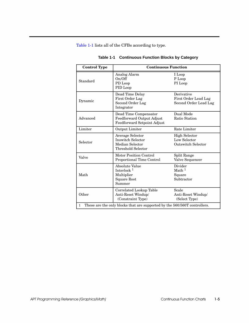
Continuous Function Charts 1-5APT Programming Reference (Graphics/Math)
Table 1-1 lists all of the CFBs according to type.
Table 1-1 Continuous Function Blocks by Category
Control Type Continuous Function
Standard
Analog Alarm I LoopOn/Off P LoopPD Loop PI LoopPID Loop
Dynamic
Dead Time Delay DerivativeFirst Order Lag First Order Lead LagSecond Order Lag Second Order Lead LagIntegrator
AdvancedDead Time Compensator Dual ModeFeedforward Output Adjust Ratio StationFeedforward Setpoint Adjust
Limiter Output Limiter Rate Limiter
Selector
Average Selector High SelectorInswitch Selector Low SelectorMedian Selector Outswitch SelectorThreshold Selector
Valve Motor Position Control Split RangeProportional Time Control Valve Sequencer
Math
Absolute Value DividerInterlock 1 Math 1
Multiplier SquareSquare Root SubtractorSummer
OtherCorrelated Lookup Table ScaleAnti-Reset Windup/ Anti-Reset Windup/(Constraint Type) (Select Type)
1 These are the only blocks that are supported by the 560/560T controllers.
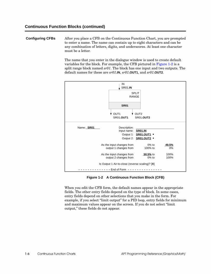
Continuous Function Charts1-6 APT Programming Reference (Graphics/Math)
Continuous Function Blocks (continued)
After you place a CFB on the Continuous Function Chart, you are promptedto enter a name. The name can contain up to eight characters and can beany combination of letters, digits, and underscores. At least one charactermust be a letter.
The name that you enter in the dialogue window is used to create defaultvariables for the block. For example, the CFB pictured in Figure 1-2 is asplit range block named sr01. The block has one input and two outputs. Thedefault names for these are sr01.IN, sr01.OUT1, and sr01.OUT2.
IN
SR01
SPLITRANGE
OUT1 OUT2
Name: SR01 Description:Input name: SR01.IN
Output 1: SR01.OUT1 SOutput 2: SR01.OUT2 S
As the input changes from 0% to 49.5%output 1 changes from 100% to 0%
As the input changes from 50.5% to 100%output 2 changes from 0% to 100%
Is Output 1 Air-to-close (reverse scaling)? [X]
-- -- -- -- -- -- -- -- -- -- -- -- -- -- End of Form -- -- -- -- -- -- -- -- -- -- -- -- -- -- --
SR01.IN
SR01.OUT1 SR01.OUT2
Figure 1-2 A Continuous Function Block (CFB)
When you edit the CFB form, the default names appear in the appropriatefields. The other entry fields depend on the type of block. In some cases,entry fields depend on other selections that you make in the form. Forexample, if you select “limit output” for a PID loop, entry fields for minimumand maximum values appear on the screen. If you do not select “limitoutput,” these fields do not appear.
Configuring CFBs

Continuous Function Charts 1-7APT Programming Reference (Graphics/Math)
APT allows you to connect the output of one CFB to the input of anotherCFB. Figure 1-3 shows two CFBs connected by a connection line.
P I D
OUT
PVSPSP
PID01
P I D
OUT
PVSPSP
PID02 OUT
PV
SIMULATE
1ST ORDERLAG
Figure 1-3 Connected CFBs
Graphically, some CFBs (such as the PID blocks in Figure 1-3) appear tohave two setpoint (SP) inputs, one on each side of the block; however, theseblocks actually have only one setpoint input. The two arrows make it easyfor you to connect a line to either side of the block. Because the two inputarrows actually represent a single setpoint input, you cannot connect linesto both setpoints.
As long as a connection line begins on an output arrow and terminates onan input arrow, you can draw it anywhere within the boundaries of a CFC.However, do not draw lines through CFB graphics; draw lines through otherlines only when unavoidable.
If you draw a connection from the input of one CFB to the output of anotherCFB, the input changes its name to the same name as the output. As longas a graphic connection exists between the two, the only way to change thename of the input is to edit the output; you cannot edit the input namedirectly.
The algorithm that controls object download affects the execution flow ofCFBs, not the apparent order indicated by the graphical connections.Although the exact order in which blocks are executed is not predictable, theorder does not change from download to download.
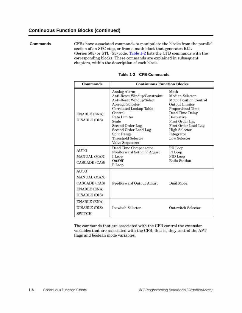
Continuous Function Charts1-8 APT Programming Reference (Graphics/Math)
Continuous Function Blocks (continued)
CFBs have associated commands to manipulate the blocks from the parallelsection of an SFC step, or from a math block that generates RLL(Series 505) or STL (S5) code. Table 1-2 lists the CFB commands with thecorresponding blocks. These commands are explained in subsequentchapters, within the description of each block.
Table 1-2 CFB Commands
Commands Continuous Function Blocks
ENABLE (ENA)
Analog Alarm MathAnti-Reset Windup/Constraint Median SelectorAnti-Reset Windup/Select Motor Position ControlAverage Selector Output LimiterCorrelated Lookup Table Proportional TimeControl Dead Time DelayR t Li it D i ti
ENABLE (ENA)
DISABLE (DIS)Rate Limiter DerivativeScale First Order LagSecond Order Lag First Order Lead LagSecond Order Lead Lag High SelectorSplit Range IntegratorThreshold Selector Low SelectorValve Sequencer
AUTO
MANUAL (MAN)
CASCADE (CAS)
Dead Time Compensator PD LoopFeedforward Setpoint Adjust PI LoopI Loop PID LoopOn/Off Ratio StationP Loop
AUTO
MANUAL (MAN)
CASCADE (CAS)
ENABLE (ENA)
DISABLE (DIS)
Feedforward Output Adjust Dual Mode
ENABLE (ENA)
DISABLE (DIS) Inswitch Selector Outswitch Selector
SWITCH
The commands that are associated with the CFB control the extensionvariables that are associated with the CFB, that is, they control the APTflags and boolean mode variables.
Commands
Continuous Function Charts 1-9APT Programming Reference (Graphics/Math)
When you create a CFB, APT automatically creates a set of extensionvariables that are associated with that CFB. The name of each variableconsists of the name of the CFB followed by a period and the extension.
For example, the .NRDY (not ready) extension is a read/write booleanvariable that you can set to true to disable the block automatically.
Some extensions are classified as “read-only”: you can read the value of theextension variable, but you cannot change its value. Other extensions areclassified as “read/write”: you can both read and change the value of thatextension variable.
You can control the mode of the CFB in the following ways:
Method Example
Use a command in an SFC Auto pid_1;
Use a command in Math Auto pid_1;
Use an APT flag On pid_1.RAUTO;
Use a boolean extension pid_1.GAUTO := true;
The command manipulates the APT flag and the boolean extensions inorder to control the CFB. Use the command, rather than the extensions, tocontrol the mode of the block, because APT can overwrite the boolean modeextensions. Use the APT flags and boolean extensions to monitor the statusof the block. If you use an APT flag extension, you must use the LATCH,ON, and CLEAR math procedures, described in Chapter 11, “MathFunctions and Procedures.”
NOTE: S5 users are familiar with the term “flag” used to refer to a singledigital point. However, an APT flag is more than this; it is a construct ofseveral points, with logic that you can manipulate by using the LATCH, ON,and CLEAR commands.
The CFB extensions are listed with the description of each block inChapters 2 through 9 of this manual. The “OSx Tag Translation” appendixin the SIMATIC APT Applications Manual contains information about howthese extensions are translated to OSx.
Extensions

Continuous Function Charts1-10 APT Programming Reference (Graphics/Math)
Continuous Function Blocks (continued)
All CFBs have extensions that provide information about any errors thatcan occur. When an error occurs in a Series 505 controller, it isautomatically stored in these error extensions. Although the extensions arealso present for CFBs programmed into an S5 controller, they contain nomeaningful information.
If an execution error occurs, the .ECODE extension contains a non-zerovalue.
The .IID extension identifies the SFPGM associated with the block.
The .SNUM extension contains the SFPGM line number that containsthe error.
Table 1-3 lists the error codes that are provided by a Series 505 controllerwhen it executes SFPGM code, and the associated number that appears inthe .ECODE extension for Series 505 controllers.
Table 1-3 CFB Error Codes (Series 505 only)
CodeMeaning
Hex DecimalMeaning
02 02 Address out of range
03 03 Requested data not found
09 09 Incorrect amount of data sent with request
11 17 Invalid data
43 67 Control block does not exist
4A 74 Attempt to access an integer variable as a real
4B 75 Attempt to access a real variable as an integer
4E 78 Attempt to write to a read-only variable
4F 79 Invalid variable data type for this operation
52 82 Invalid returned value
53 83 Attempt to use lead-lag procedure in event or continuousmath block
58 88 Stack overflow while evaluating IF...THEN statement
5A 90 Arithmetic overflow
5B 91 Invalid operator in an IF...THEN statement
5D 93 Attempt to divide by zero
60 96 Invalid data type code (usually in IF...THEN statement)
Error-CodeExtensions

Standard Control Blocks 2-1APT Programming Reference (Graphics/Math)
Chapter 2
Standard Control Blocks
2.1 Understanding Standard Control Blocks 2-2. . . . . . . . . . . . . . . . . . . . . . . . . . . . . . . . . . . . . . . . .Overview 2-2. . . . . . . . . . . . . . . . . . . . . . . . . . . . . . . . . . . . . . . . . . . . . . . . . . . . . . . . . . . . . . . . . . . . . . .Availability 2-2. . . . . . . . . . . . . . . . . . . . . . . . . . . . . . . . . . . . . . . . . . . . . . . . . . . . . . . . . . . . . . . . . . . . . .Loop Control 2-2. . . . . . . . . . . . . . . . . . . . . . . . . . . . . . . . . . . . . . . . . . . . . . . . . . . . . . . . . . . . . . . . . . . .
2.2 PID Blocks 2-3. . . . . . . . . . . . . . . . . . . . . . . . . . . . . . . . . . . . . . . . . . . . . . . . . . . . . . . . . . . . . . . . . . . . .Overview 2-3. . . . . . . . . . . . . . . . . . . . . . . . . . . . . . . . . . . . . . . . . . . . . . . . . . . . . . . . . . . . . . . . . . . . . . .Availability 2-3. . . . . . . . . . . . . . . . . . . . . . . . . . . . . . . . . . . . . . . . . . . . . . . . . . . . . . . . . . . . . . . . . . . . . .Standard PID Algorithm (Position Algorithm) 2-4. . . . . . . . . . . . . . . . . . . . . . . . . . . . . . . . . . . . . . . .Velocity Algorithm 2-4. . . . . . . . . . . . . . . . . . . . . . . . . . . . . . . . . . . . . . . . . . . . . . . . . . . . . . . . . . . . . . .PID Loop CFB and Form 2-5. . . . . . . . . . . . . . . . . . . . . . . . . . . . . . . . . . . . . . . . . . . . . . . . . . . . . . . . .Process Variable Information 2-9. . . . . . . . . . . . . . . . . . . . . . . . . . . . . . . . . . . . . . . . . . . . . . . . . . . . . .Process Setpoint Information 2-11. . . . . . . . . . . . . . . . . . . . . . . . . . . . . . . . . . . . . . . . . . . . . . . . . . . . . .Output Information 2-13. . . . . . . . . . . . . . . . . . . . . . . . . . . . . . . . . . . . . . . . . . . . . . . . . . . . . . . . . . . . . . .Controller Options 2-15. . . . . . . . . . . . . . . . . . . . . . . . . . . . . . . . . . . . . . . . . . . . . . . . . . . . . . . . . . . . . . .Error Algorithm 2-15. . . . . . . . . . . . . . . . . . . . . . . . . . . . . . . . . . . . . . . . . . . . . . . . . . . . . . . . . . . . . . . . . .Direct/Reverse Acting Control 2-15. . . . . . . . . . . . . . . . . . . . . . . . . . . . . . . . . . . . . . . . . . . . . . . . . . . . .Freeze Bias 2-16. . . . . . . . . . . . . . . . . . . . . . . . . . . . . . . . . . . . . . . . . . . . . . . . . . . . . . . . . . . . . . . . . . . .Associated Math 2-17. . . . . . . . . . . . . . . . . . . . . . . . . . . . . . . . . . . . . . . . . . . . . . . . . . . . . . . . . . . . . . . .Tuning Parameters 2-19. . . . . . . . . . . . . . . . . . . . . . . . . . . . . . . . . . . . . . . . . . . . . . . . . . . . . . . . . . . . . .PID Commands and Flags 2-21. . . . . . . . . . . . . . . . . . . . . . . . . . . . . . . . . . . . . . . . . . . . . . . . . . . . . . . .Loops in Manual Mode 2-22. . . . . . . . . . . . . . . . . . . . . . . . . . . . . . . . . . . . . . . . . . . . . . . . . . . . . . . . . . .Loops in Automatic Mode 2-22. . . . . . . . . . . . . . . . . . . . . . . . . . . . . . . . . . . . . . . . . . . . . . . . . . . . . . . . .Loops in Cascade Mode 2-22. . . . . . . . . . . . . . . . . . . . . . . . . . . . . . . . . . . . . . . . . . . . . . . . . . . . . . . . . .PID Extensions 2-23. . . . . . . . . . . . . . . . . . . . . . . . . . . . . . . . . . . . . . . . . . . . . . . . . . . . . . . . . . . . . . . . .Availability 2-23. . . . . . . . . . . . . . . . . . . . . . . . . . . . . . . . . . . . . . . . . . . . . . . . . . . . . . . . . . . . . . . . . . . . . .PID V-Flag and C-Flag Extension Variables 2-25. . . . . . . . . . . . . . . . . . . . . . . . . . . . . . . . . . . . . . . . .Loop Status Extensions 2-27. . . . . . . . . . . . . . . . . . . . . . . . . . . . . . . . . . . . . . . . . . . . . . . . . . . . . . . . . .Reset Windup Protection and the .AWS Extension 2-28. . . . . . . . . . . . . . . . . . . . . . . . . . . . . . . . . . .Map Tuning and Alarm Data to 505 S-Memory 2-29. . . . . . . . . . . . . . . . . . . . . . . . . . . . . . . . . . . . . . .RTD and Thermocouple Module Extensions for Series 505 2-31. . . . . . . . . . . . . . . . . . . . . . . . . . . .
2.3 On/Off Block 2-32. . . . . . . . . . . . . . . . . . . . . . . . . . . . . . . . . . . . . . . . . . . . . . . . . . . . . . . . . . . . . . . . . . .Overview 2-32. . . . . . . . . . . . . . . . . . . . . . . . . . . . . . . . . . . . . . . . . . . . . . . . . . . . . . . . . . . . . . . . . . . . . . .Availability 2-32. . . . . . . . . . . . . . . . . . . . . . . . . . . . . . . . . . . . . . . . . . . . . . . . . . . . . . . . . . . . . . . . . . . . . .Block Configuration 2-32. . . . . . . . . . . . . . . . . . . . . . . . . . . . . . . . . . . . . . . . . . . . . . . . . . . . . . . . . . . . . .On/Off Commands 2-35. . . . . . . . . . . . . . . . . . . . . . . . . . . . . . . . . . . . . . . . . . . . . . . . . . . . . . . . . . . . . .On/Off Extensions 2-36. . . . . . . . . . . . . . . . . . . . . . . . . . . . . . . . . . . . . . . . . . . . . . . . . . . . . . . . . . . . . . .
2.4 Analog Alarm Block 2-38. . . . . . . . . . . . . . . . . . . . . . . . . . . . . . . . . . . . . . . . . . . . . . . . . . . . . . . . . . . .Overview 2-38. . . . . . . . . . . . . . . . . . . . . . . . . . . . . . . . . . . . . . . . . . . . . . . . . . . . . . . . . . . . . . . . . . . . . . .Availability 2-38. . . . . . . . . . . . . . . . . . . . . . . . . . . . . . . . . . . . . . . . . . . . . . . . . . . . . . . . . . . . . . . . . . . . . .Analog Alarm Commands 2-40. . . . . . . . . . . . . . . . . . . . . . . . . . . . . . . . . . . . . . . . . . . . . . . . . . . . . . . .Analog Alarm Extensions 2-40. . . . . . . . . . . . . . . . . . . . . . . . . . . . . . . . . . . . . . . . . . . . . . . . . . . . . . . . .Analog Alarm V-Flag and C-Flag Extension Variables 2-42. . . . . . . . . . . . . . . . . . . . . . . . . . . . . . . . .Associated Math 2-43. . . . . . . . . . . . . . . . . . . . . . . . . . . . . . . . . . . . . . . . . . . . . . . . . . . . . . . . . . . . . . . .S-Memory Variables (Series 505 only) 2-44. . . . . . . . . . . . . . . . . . . . . . . . . . . . . . . . . . . . . . . . . . . . . .

Standard Control Blocks2-2 APT Programming Reference (Graphics/Math)
2.1 Understanding Standard Control Blocks
APT provides three basic types of standard control blocks:
PID blocks provide standard combinations of proportional, integral,and derivative control.
On/off blocks incorporate a high-gain PID loop and convert the outputto a boolean value.
Analog alarm blocks provide a range check on an analog input.
All of the standard control blocks are supported for Series 505 and S5controllers. The standard control blocks are not supported for the 560/560Tcontrollers.
Figure 2-1 shows the basic operation of a continuous process loop.
Controldevice
+
--
Setpoint(desiredvalue)
Error
Process variable(sensed value)
Controller
Outputsignal
Process
Controlled variable
Figure 2-1 Process Control Loop
In a typical loop operation, a measured process variable is compared to asetpoint, or desired value. The difference between these two values is theerror signal that the controller uses to calculate an output to the controldevice. The control device, in turn, manipulates the controlled variable thatserves as an input to the process.
Overview
Availability
Loop Control

PID
Standard Control Blocks 2-3APT Programming Reference (Graphics/Math)
2.2 PID Blocks
The PID loops provide a combination of proportional, integral, andderivative control to calculate the value of an output. The output is based onthe error (the relationship between the setpoint and the process variable).
In proportional control, the output is proportional to the error and isbased on the formula:
M= Kc E + Mx
M = output, E = error = setpoint --- process variable
Kc = gain =∆output∆input
where
In integral control, the output is based on the integral of the error withrespect to time. Integral mode can be combined with proportionalcontrol or with proportional and derivative control. Integral controluses the formula:
M= TsTi
where Ts = sample time, Ti = reset time, E = error at time J
Σn
J=0Ej
In derivative control, the output is based on the rate of change of theprocess variable. Derivative control is never used alone, but always incombination with proportional and/or integral control:
M= ---TdTsdPVdt
where Ts = sample time, Td = rate time, PV = process variable
PID loops are available for both Series 505 and S5 controllers; however, forthe Series 505, the PID loop is part of the firmware, while for the S5 theloop has been implemented through code. Consequently, the S5 PID loop hasseveral distinctive features:
The Series 505 S-memory mapping feature is not supported for S5.
The process variable for S5 controllers must be a real number, forinstance, a scaled analog input; the PID output must be a real number,for instance, an analog output.
The PLC Reserved Address feature is not supported for S5.
The broken transmitter signal is an AI extension and not a loopextension for S5.
Overview
Availability
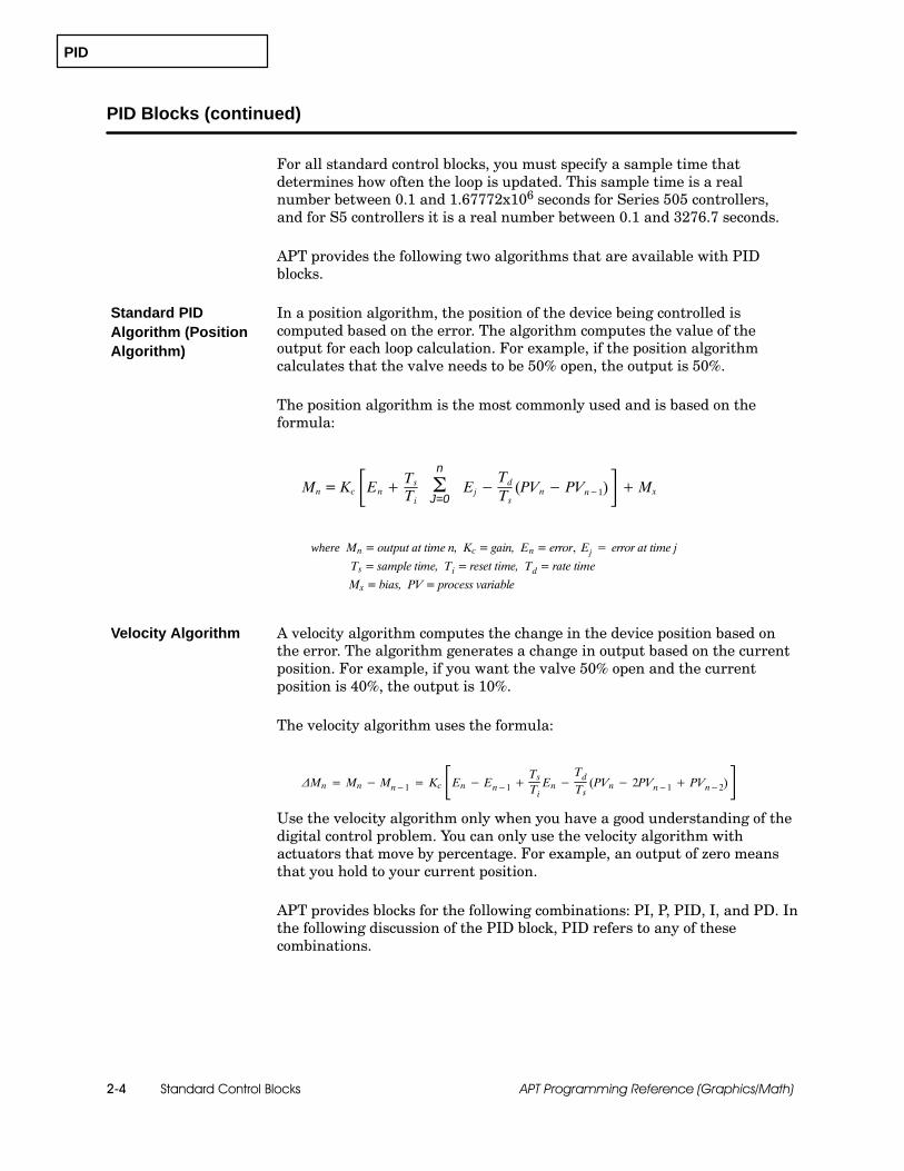
PID
Standard Control Blocks2-4 APT Programming Reference (Graphics/Math)
PID Blocks (continued)
For all standard control blocks, you must specify a sample time thatdetermines how often the loop is updated. This sample time is a realnumber between 0.1 and 1.67772x10⁶ seconds for Series 505 controllers,and for S5 controllers it is a real number between 0.1 and 3276.7 seconds.
APT provides the following two algorithms that are available with PIDblocks.
In a position algorithm, the position of the device being controlled iscomputed based on the error. The algorithm computes the value of theoutput for each loop calculation. For example, if the position algorithmcalculates that the valve needs to be 50% open, the output is 50%.
The position algorithm is the most commonly used and is based on theformula:
Mn = Kc ÀEn+ TsTi Ej−TdTs(PVn− PVn−1)Ã+Mx
Mn = output at time n, Kc = gain, En = error, Ej = error at time jwhere
Ts = sample time, Ti = reset time, Td = rate time
Mx = bias, PV = process variable
n
ΣJ=0
A velocity algorithm computes the change in the device position based onthe error. The algorithm generates a change in output based on the currentposition. For example, if you want the valve 50% open and the currentposition is 40%, the output is 10%.
The velocity algorithm uses the formula:
∆Mn = Mn− Mn−1 = Kc ÀEn− En−1+ TsTi En−TdTs(PVn− 2PVn−1+ PVn−2)Ã
Use the velocity algorithm only when you have a good understanding of thedigital control problem. You can only use the velocity algorithm withactuators that move by percentage. For example, an output of zero meansthat you hold to your current position.
APT provides blocks for the following combinations: PI, P, PID, I, and PD. Inthe following discussion of the PID block, PID refers to any of thesecombinations.
Standard PIDAlgorithm (PositionAlgorithm)
Velocity Algorithm

PID
Standard Control Blocks 2-5APT Programming Reference (Graphics/Math)
Figure 2-2 shows the PID Loop CFB graphic.
OUT
SP
PID loop
xxxxxx.OUT
xxxxxx.PVPV
P
I
D
P I D
OUT
PVSPSP
xxxxxx
xxxxxx
Figure 2-2 PID Loop CFB
Figure 2-3 shows the PID form with default values and default names thatare based on the name that you enter when you create the CFB graphic.The shaded entries in the form depend on a previous selection and are not apart of the initial display.
The details of each entry are explained on page 2-9 for process variableinformation, page 2-11 for process setpoint information, page 2-13 for outputinformation, page 2-15 for controller options, page 2-17 for associated math,and page 2-19 for tuning parameters.
The various fields in the PID form are described below and on subsequentpages.
Sample time: The sample time in seconds determines how often the loop,the deviation alarm bits, and the associated math are evaluated andupdated; default is 1; the value is measured in tenth-of-a-secondincrements, between 0.1 and 1.67772 ⌠ 106 for Series 505 controllers, orbetween 0.1 and 3276.7 for S5 controllers.
Algorithm type: POSITION or VELOCITY; default is POSITION.
PLC address (automatic or user assigned): (Series 505 only) Default isautomatic. Automatic allows APT to assign a loop address. User assignedallows you to specify the loop address, e.g., %loop1.
Reserved address: (Series 505 only) This is the starting controller addressfor the specified loop, e.g., %loop1. You do not have to reserve Series 505S-memory, but you must reserve a loop in the Compiler Control file.
Process variable: For Series 505, the name of the analog input, integer,scaled integer, or real input that represents the process variable. For S5, thename of the scaled analog input or real input that represents the processvariable. Integer inputs are not allowed for S5.
PID Loop CFB andForm
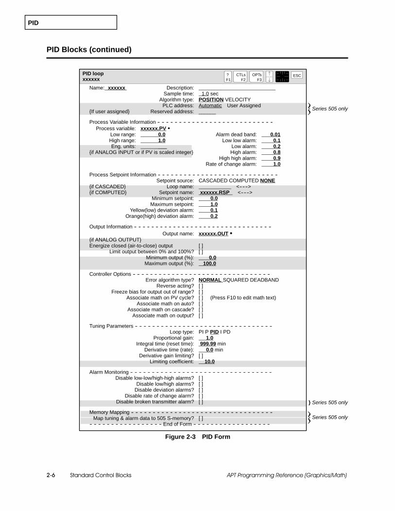
PID
Standard Control Blocks2-6 APT Programming Reference (Graphics/Math)
PID Blocks (continued)
PID loopxxxxxx
?F1
ESCCTLsF2
OPTsF3
} Series 505 only
Series 505 only
Name: xxxxxx Description:Sample time: 1.0 sec
Algorithm type: POSITION VELOCITYPLC address: Automatic User Assigned
{If user assigned} Reserved address: ______
Process Variable Information -- -- -- -- -- -- -- -- -- -- -- -- -- -- -- -- -- -- -- -- -- -- -- -- -- -- --Process variable: xxxxxx.PV S
Low range: 0.0 Alarm dead band: 0.01High range: 1.0 Low low alarm: 0.1Eng. units: ___ Low alarm: 0.2
{if ANALOG INPUT or if PV is scaled integer} High alarm: 0.8High high alarm: 0.9
Rate of change alarm: 1.0
Process Setpoint Information -- -- -- -- -- -- -- -- -- -- -- -- -- -- -- -- -- -- -- -- -- -- -- -- -- -- -- --Setpoint source: CASCADED COMPUTED NONE
{if CASCADED} Loop name: <------>{if COMPUTED} Setpoint name: xxxxxx.RSP <------>
Minimum setpoint: 0.0Maximum setpoint: 1.0
Yellow(low) deviation alarm: 0.1Orange(high) deviation alarm: 0.2
Output Information -- -- -- -- -- -- -- -- -- -- -- -- -- -- -- -- -- -- -- -- -- -- -- -- -- -- -- -- -- -- -- --Output name: xxxxxx.OUT S
{if ANALOG OUTPUT}Energize closed (air-to-close) output [ ]
Limit output between 0% and 100%? [ ]Minimum output (%): 0.0
Maximum output (%): 100.0
Controller Options -- -- -- -- -- -- -- -- -- -- -- -- -- -- -- -- -- -- -- -- -- -- -- -- -- -- -- -- -- -- -- --Error algorithm type? NORMAL SQUARED DEADBAND
Reverse acting? [ ]Freeze bias for output out of range? [ ]
Associate math on PV cycle? [ ] (Press F10 to edit math text)Associate math on auto? [ ]
Associate math on cascade? [ ]Associate math on output? [ ]
Tuning Parameters -- -- -- -- -- -- -- -- -- -- -- -- -- -- -- -- -- -- -- -- -- -- -- -- -- -- -- -- -- -- -- --Loop type: PI P PID I PD
Proportional gain: 1.0Integral time (reset time): 999.99 min
Derivative time (rate): 0.0 minDerivative gain limiting? [ ]
Limiting coefficient: 10.0
Alarm Monitoring -- -- -- -- -- -- -- -- -- -- -- -- -- -- -- -- -- -- -- -- -- -- -- -- -- -- -- -- -- -- -- -- --Disable low-low/high-high alarms? [ ]
Disable low/high alarms? [ ]Disable deviation alarms? [ ]
Disable rate of change alarm? [ ]Disable broken transmitter alarm? [ ]
Memory Mapping -- -- -- -- -- -- -- -- -- -- -- -- -- -- -- -- -- -- -- -- -- -- -- -- -- -- -- -- -- -- -- -- --Map tuning & alarm data to 505 S-memory? [ ]
-- -- -- -- -- -- -- -- -- -- -- -- -- -- -- -- -- End of Form -- -- -- -- -- -- -- -- -- -- -- -- -- -- -- -- -- --Series 505 only
Figure 2-3 PID Form

PID
Standard Control Blocks 2-7APT Programming Reference (Graphics/Math)
Low range: Real number in engineering units that is the low range of thePV. Used for alarming; for Series 505, also used to scale an integer PV. If PVis an analog input, this value is taken from the values that you entered inthe I/O Table. For Series 505, if PV is a scaled integer, this value is takenfrom the value entered in the Declaration Table.
High range: Real number in engineering units that is the high range of thePV. Used for alarming; for Series 505, also used to scale an integer PV. If PVis an analog input, this value is taken from the values that you entered inthe I/O Table. For Series 505, if PV is a scaled integer, this value is takenfrom the value entered in the Declaration Table.
Eng. units: Optional documentation field to describe units of final, scaledvalue (eight characters maximum); appears only if AI or SI is selected asinput.
Alarm deadband: Real number in engineering units; prevents the alarmfrom changing when the process variable is within the deadband.
Low low alarm: Real number in engineering units; must be less than orequal to low alarm value and greater than or equal to low range of PV.
Low alarm: Real number in engineering units; must be less than or equalto high alarm value of PV.
High alarm: Real number in engineering units; must be less than or equalto high high alarm value of PV.
High high alarm: Real number in engineering units; must be greater thanor equal to high alarm value and less than or equal to high range of PV.
Rate of change alarm: Real number in engineering units/minute that isused to set rate-of-change alarm.
Setpoint source: CASCADED, COMPUTED, or NONE; default is NONE.
Loop name: Name of PID loop that holds setpoint (SP) input if setpointsource is cascaded.
Setpoint name: Name of real variable that indicates setpoint (SP) input ifsetpoint source is computed.
Minimum setpoint: Real number that indicates minimum value ofsetpoint; must be greater than or equal to the low range of the PV.
Maximum setpoint: Real number that indicates maximum value ofsetpoint; must be less than or equal to the high range of the PV.
Yellow deviation alarm: Value that indicates the maximum allowableerror (SP -- PV) for the yellow deviation zone is reached.
Orange deviation alarm: Value that indicates the maximum allowableerror (SP -- PV) for the orange deviation zone is reached.
Output name: Name of the output variable.

PID
Standard Control Blocks2-8 APT Programming Reference (Graphics/Math)
PID Blocks (continued)
Energize closed output: X indicates the analog output is air-to-close; ablank field indicates the analog output is air-to-open. If energized closed isselected, the output signal is inverted so that .LMN goes from one to zero as.OUT goes from zero to one; it does not invert the sign of the error term asdoes reverse acting.
Limit output between 0% and 100%: X indicates that you want to restrictoutput range to something less than 0.0 to 100.0 for position algorithm or--100.0 to 100.0 for velocity algorithm.
Minimum output: Real number that sets low limit; value must be between0.0 to 100.0 for position algorithm or --100.0 to 100.0 for velocity algorithm.
Maximum output: Real number that sets high limit; value must bebetween 0.0 to 100.0 for position algorithm or --100.0 to 100.0 for velocityalgorithm.
Error algorithm: NORMAL, SQUARED, or DEADBAND; default isNORMAL.
Reverse acting: X indicates that you want to use the reverse-acting controlalgorithm; a blank field indicates direct-acting.
Freeze bias for output out of range: X indicates that you wantfreeze-bias anti-reset windup algorithm; blank indicates that you want biasbacktracking.
Associate math: X indicates that you want to include additional math onPV cycle, auto, cascade, or on output.
Loop type: P, PI, PD, or PID; default is PID. The type of loop you choosedetermines which tuning constants are available to you; the others areforced to non-operational values. See Figure 2-8.
Proportional gain: Integer between 0 and 100 that indicates proportionalgain in % / %; default is 1.
Integral time (reset time): Real number between 0.0 and infinity thatindicates reset time of integral mode in minutes; default is 999.99.
Derivative time (rate): Real number between 0 and infinity that indicatesthe derivative time (rate) in minutes; default is 0.0.
Derivative gain limiting: X indicates that you want to limit the derivativegain. You must then enter the limiting coefficient.
Disable alarm monitoring: X indicates that you do not want to monitorthe indicated alarm.
Map tuning and alarm data to S-memory: (Series 505 only)X indicates that APT does not map PID alarm and tuning parameters fromSeries 505 V-memory to S-memory, but rather uses the existing Series 505S-memory alarm and tuning parameters.

PID
Standard Control Blocks 2-9APT Programming Reference (Graphics/Math)
The process variable to the PID block is automatically designatedcfb_name.PV. If you have a Series 505 controller, you can change this to thename of any analog, integer, scaled integer, or real input that you define inthe I/O Name or Declaration Tables, described in the SIMATIC APTProgramming Reference (Tables) Manual. If you have an S5 controller, youcan change the name of the PV to any scaled analog input or real input thatyou have defined. S5 controllers must have real PVs; integer PVs are notprocessed. If you want to use integers for PVs, see the SIMATIC APTApplications Manual , Chapter 2, for programming hints abo utincorporating integer inputs for an S5 PID. If the block is graphicallyconnected to another block, the process variable name is insertedautomatically.
Process VariableInformation

PID
Standard Control Blocks2-10 APT Programming Reference (Graphics/Math)
PID Blocks (continued)
High and low limits for the process variable are used to set the high andlow range for a real number input. For Series 505 controllers, they can alsobe used to scale an integer variable input.
If the input is a real (S5 or Series 505) or integer (Series 505 only)variable, you specify the high and low values in the PID form.
If the input is an analog input or scaled integer, the high and lowranges are automatically those that you specify when you define theanalog input in the I/O Symbolic Name Table, or when you define thescaled integer in the Declaration Table.
Alarm definitions allow you to monitor the process variable for deviationoutside a specified range. The standard control blocks provide low-low, low,high, and high-high alarms; see Figure 2-4. If the process variable is outsidethe limits of the alarms, you may use the alarms to generate warnings andshutdown procedures for the process equipment itself.
The alarm deadband prevents the alarm from changing when the processvariable is within the specified deadband of each alarm zone.
A rate-of-change alarm allows you to monitor how fast the processvariable is changing.
These alarms are monitored at the lesser frequency: every 2 seconds or thesample time. To change the alarm values, you write to the correspondingextension variables listed in Table 2-2 on page 2-23.
Low alarm
Low-low alarm
High-high alarm
High alarm
Alarm dead band
Alarm dead band
Alarm dead band
Alarm dead band
Processvariable
high alarm low alarm
Figure 2-4 Process Variable Alarms
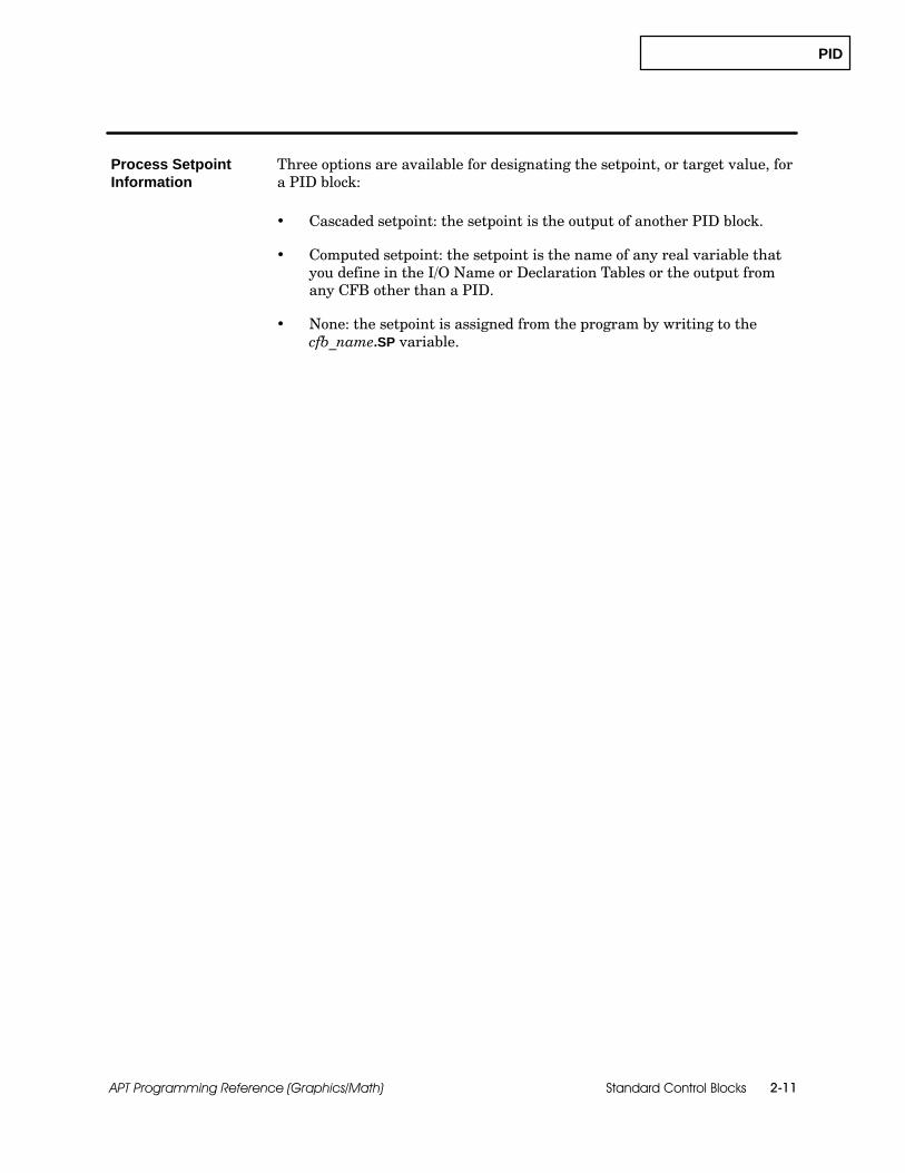
PID
Standard Control Blocks 2-11APT Programming Reference (Graphics/Math)
Three options are available for designating the setpoint, or target value, fora PID block:
Cascaded setpoint: the setpoint is the output of another PID block.
Computed setpoint: the setpoint is the name of any real variable thatyou define in the I/O Name or Declaration Tables or the output fromany CFB other than a PID.
None: the setpoint is assigned from the program by writing to thecfb_name.SP variable.
Process SetpointInformation

PID
Standard Control Blocks2-12 APT Programming Reference (Graphics/Math)
PID Blocks (continued)
Minimum andmaximum setpoint values define the range of the setpointvalue. These values must be within the range of the process variable.
Deviation alarms (yellow/low and orange/high) refer to the specifiedtolerance around the setpoint; that is, they check to see whether the processvariable is within a desired range of the setpoint. The yellow and orangedeviation zones move up and down with the setpoint as it changes (seeFigure 2-5). The yellow/low deviation is closer to the setpoint, and theorange/high deviation is farther away from the setpoint. To change thedeviation alarm values, write to the corresponding extension variables,listed in Table 2-2.
The alarm deadband that you specified for the process variable alarmsoperates around the deviation alarms also.
The deviation alarms can be used as indicators to show how well the loop iscontrolling, or they can be used as limits to activate some procedure.
Setpoint
Yellow deviation
Yellow deviation
Orange deviation
Orange deviation
dead band
dead band
dead band
dead band
Figure 2-5 Setpoint Deviation Alarms

PID
Standard Control Blocks 2-13APT Programming Reference (Graphics/Math)
The output from the PID block is automatically designated cfb_name.OUT. Ifyou have a Series 505 controller, you can change this to the name of anyreal, integer, analog output variable, or cfb_name.IOUT. If you have an S5controller, you can change this to the name of any real variable or analogoutput; the S5 PID does not process integers. If the output is an analogoutput (AO) variable, the PID automatically provides the appropriatescaling that you defined in the I/O Name Table.
The output from a PID is limited to a specific range.
The range for a position algorithm is 0.0 to 1.0. For a positionalgorithm, the values of the .HLIM and .LLIM extensions should bebetween 0.0 and 1.0, where 0.0 = 0% and 1.0 = 100%.
The range for a velocity algorithm is --1.0 to +1.0. For a velocityalgorithm, the values of the .HLIM and .LLIM extensions should bebetween --1.0 and 1.0, where --1.0 = --100% and 1.0 = 100%.
If your analog output is air-to-close, you can specify that the output beenergize-closed by placing X in the Energize Closed Output field. The outputsignal is inverted such that zero to one becomes one to zero. This option doesnot invert the sign of the error term as does a reverse acting loop.
You can specify other values as the minimum and maximum outputs byplacing X in the Limit Output field. The values that you specify must bewithin the normal range for the corresponding algorithm. These limits onlyapply when the loop is in the AUTO or CASCADE modes.
Figure 2-6 shows the output parameters for a PID loop.
Output Information

PID
Standard Control Blocks2-14 APT Programming Reference (Graphics/Math)
PID Blocks (continued)
Energize Closed (air-to-close) Output: X indicates that the outputsignal is inverted so that .LMN goes from one to zero as .OUT goes fromzero to one; option appears when the output is an analog output variable.APT calculates the .LMN output as: .LMN = (1 -- .OUT)
This calculation is done for all three loop modes: Manual, Auto, andCascade.
NOTE: With Series 505 controllers, the air-to-close calculation cannot bemade when you indicate X to select Map tuning and alarm data to S-memory. Ifyou want to perform the air-to-close calculation, you need to have the Series505 V-memory mapping to S-memory. S5 controllers do not need theremapping to perform the air-to-close calculation.
Limit Output: X indicates that you wish to change the minimum andmaximum output values from their defaults. The values must be between 0and 100 for the position algorithm and --100.0 to 100.0 for the velocityalgorithm. Marking this field automatically gives you the Freeze Biasoption, even though it is not marked.
Output Information -- -- -- -- -- -- -- -- -- -- -- -- -- -- -- -- -- -- -- -- -- -- -- -- -- -- -- -- -- -- -- -- -- -- --Output name: xxxxxx.OUT
{if ANALOG OUTPUT}Energize Closed (air--to--close) Output [ ]
Limit output between 0% and 100%? [X]Minimum output (%): 0.0
Maximum output (%): 100.0
Figure 2-6 Output Parameters for PID Loop
You cannot edit the Limit Output field if you have already marked the PIDblock for OSx tag translation.
PID
Standard Control Blocks 2-15APT Programming Reference (Graphics/Math)
When you define the PID block, you have the following controller options:an error algorithm, direct or reverse control, freeze bias for an out-of-rangeoutput, and associated math.
The error algorithm can be normal, squared, or deadband:
Normal error algorithm provides control based on the value of theerror.
Squared error algorithm provides control based on the value of thesquare of the error. This produces a control equation that is lessresponsive than normal error control.
Deadband error algorithm provides control based on an error deadbandthat eliminates gain for small errors within the deadband. Thedeadband is defined by the yellow deviation alarm limit.
The control calculation in the PID CFB can be either direct- orreverse-acting:
Direct-acting control means that when you increase the setpoint, theoutput increases, and when you decrease the setpoint, the outputdecreases. The control action is relative to the change in loop error. Ifthe error increases, then the controller increases the output.
Example: An example of direct-acting control is heating a vessel witha steam jacket. When heating, the setpoint is higher than the PV,resulting in a positive error. To achieve optimum control, the PID firstassigns a large output value to the valve that controls the flow ofsteam, and then reduces the output value as the temperature in thevessel increases. The output to the steam valve continues to decreaseas the temperature increases until a steady-state output is reachedthat maintains the temperature at the setpoint.
Reverse-acting control decreases the output if the setpoint is increased,and increases the output if the setpoint is decreased. The direction ofchange in the setpoint and output is opposite. If the error increases(goes positive), then the controller decreases the output.
Example: An example of reverse-acting control is cooling a vessel withcoolant in the jacket. When cooling, the setpoint is lower than the PV,resulting in a negative error. The PID achieves optimum control by firstassigning a large output value to the valve that controls the flow ofcoolant, and then reduces the output as the temperature in the vesseldecreases. The output to the coolant valve continues to decrease as thetemperature decreases until a steady-state output is reached thatmaintains the temperature at the setpoint.
Controller Options
Error Algorithm
Direct/ReverseActing Control

PID
Standard Control Blocks2-16 APT Programming Reference (Graphics/Math)
PID Blocks (continued)
There is one difference between reverse-acting calculations anddirect-acting calculations. In reverse-acting calculations, the tuningparameters have been negated to correct the control algorithm tocompensate for the reverse action; this is not necessary in direct-actingcalculations.
Reset windup occurs in a PID loop whenever the output of the loop is nolonger able to change the process variable by adjusting the output. In thissituation, the integral mode continues to increase or decrease the output:this action has no effect on the controlled variable.
The controller has built-in reset windup protection for the PID loop thatmonitors the output and detects an attempt to move the output beyond 0.0or 100.0 percent.
Two types of reset windup protection are available, depending on whetheryou use the Freeze bias for output option or not.
If you select the Freeze bias option, the anti-reset windup algorithmstops the integral mode from changing the bias whenever the outputexceeds the high or low limit. This freeze bias is also availableautomatically if you select Limit output between 0 and 100%.
If you do not select the Freeze bias option, the algorithm uses biasbacktracking and computes what the bias needs to be in order to makethe output equal to the high or low output limit.
If you need to limit the output further, you can provide additional anti-resetwindup protection by writing directly to the .AWS extension (explained onpage 2-28).
Freeze Bias

PID
Standard Control Blocks 2-17APT Programming Reference (Graphics/Math)
To expand the capability of the PID blocks, you can append Mathcomputations to the operation. This is referred to as associated math in theform. For Series 505, this math compiles as SFPGM; for S5 controllers,associated math compiles as STL.
Associate math on PV cycle? This math code executes in manual,automatic, and cascade modes before the PID calculation is performed.Preprocessing of the process variable, such as special filtering, occurs inthis section.
To modify the loop process variable from within an associated mathblock, manipulate the .LPV (loop process variable) extension, not the .IN(input) extension. APT loads the .IN value into the .LPV extensionbefore executing the associated math and uses the .LPV extension in thecomputations.
This section executes either every two seconds or at the sample time,whichever is quicker.
Associate math on auto? This math code executes only when thecontroller is in automatic mode. Special computations on the setpointoccurs in this section.
To modify the setpoint in the loop, manipulate the .LSP (internal loopsetpoint) extension, not the .SP (setpoint) extension. APT loads the .SPvalue into the .LSP extension before executing the associated math anduses the .LSP extension in the computations.
Associate math on cascade? Math code in this section executes onlywhen the controller is in cascade mode. Special computations on theremote setpoint occurs in this section.
To modify the setpoint in the loop, manipulate the .LSP extension, notthe .RSP (remote setpoint) extension. APT loads the .RSP value into the.LSP extension before executing the associated math and uses the .LSPextension in the computations.
Associated Math

PID
Standard Control Blocks2-18 APT Programming Reference (Graphics/Math)
PID Blocks (continued)
For Series 505 controllers, the .IPV extension variable contains the scaledinteger representation of the internal process variable. The .ISP variablecontains the scaled integer representation of the internal setpoint. Thesevariables can be used in associated math to convert the corresponding valueto a fractional value (.ISP -- .IPV / 100.0) without concern for engineeringunits. The .IPV and .ISP extension variables are not available for S5controllers.
Associate math on output? Math code in this section executes in AUTOor CASCADE modes after the loop calculation, but before the fieldvalue of the loop output is updated.
If you want to modify the output after the loop computation, but beforethe field update, manipulate the .LMN (internal loop output) extension,not the .OUT extension. APT performs the loop calculation and thenloads the .LMN extension into the .OUT extension. For air-to-close onanalog output, .LMN goes from zero to one for the associated math onoutput and one to zero after the associated math on output is complete.
Use the internal loop variables, .LPV, .LSP, and .LMN, only within theassociated math for the loop. In all other areas of APT, use the .PV (for S5 orSeries 505) or .IPV (Series 505 only) extension to access the process variablefor the loop and the .OUT (for S5 or Series 505) or .IOUT (Series 505 only)extension to access the output; to access the setpoint, use the .SP extensionin automatic mode and the .RSP extension in cascade mode.
The full functionality of the Math language is available in associated math,except for the following restrictions.
Associated math does not support INIT, BEGIN, and BODYstatements. Enter your Math language statements without using INIT,BEGIN, or BODY.
Associated math does not support declaration of local variables.
Associated math does not support direct addressing for S5, except in aninline assembly math statement. (See Appendix C for a discussion ofthe inline assembly math statement.) Some direct addressing ispermitted for Series 505.
%T1 through %T9 are reserved for special purposes, but Series 505controllers can use %T10 through %T15 as local variables.
Associated math is SFPGM-only for Series 505; you cannot use anyRLL-only functions in associated math if you have a Series 505controller.

PID
Standard Control Blocks 2-19APT Programming Reference (Graphics/Math)
Your selection of a loop type, such as P or PI, determines which values areforced into the loop tuning constants.
When the loop type is not PID, APT continuously supplies an appropriatevalue in the controller. When the loop type has no proportional (P) term, theextension .KC is zero. When the loop type has no integral (I) term, theextension .TI is 1.0 ⌠ 1018. When the loop type has no derivative (D) term,the extension .TD is zero.
Figure 2-7 shows the tuning parameters for a PID Loop. Figure 2-8 showstuning parameters for the other combinations of proportional, integral, andderivative control.
Tuning Parameters -- -- -- -- -- -- -- -- -- -- -- -- -- -- -- -- -- -- -- -- -- -- -- -- -- -- -- -- -- -- --Loop type: PI P PID I PD
Proportional gain: 1Integral time (reset time): 999.99 min
Derivative time (rate): 0.0 minDerivative gain limiting? [X]
Limiting coefficient? 10.0
-- -- -- -- -- -- -- -- -- -- -- -- -- -- -- -- -- End of Form -- -- -- -- -- -- -- -- -- -- -- -- -- -- -- -- -- --
Figure 2-7 Tuning Parameters for PID Loop
Proportional gain: Integer between zero and infinity that indicatesproportional gain in % / %; default is 1.
Integral time (reset time): Real number between 0.0 and infinity thatindicates reset time of integral mode in minutes; default is 999.99.
Derivative time (rate): Real number between 0.0 and infinity thatindicates the derivative time rate in minutes; default is 0.0.
Derivative gain limiting: X limits the derivative gain. See discussionbelow.
Limiting coefficient: real number between 5.0 and 30.0 that you enter ifyou select derivative gain limiting; default is 10.
In the standard PID algorithm, the algorithm responds excessively toprocess noise if the coefficient of the derivative term (Td/Ts) is significantlyabove the 10 to 20 range. This causes disturbances that lead to erraticbehavior of the process.
To solve this problem, the controller allows you the option of selecting aderivative gain limiting coefficient (Kd). The use of this coefficient enablesthe process variable to be filtered with a time constant that is proportionalto the derivative time (Td). The PID equations with the derivative gainlimiting coefficient are shown on the following page (top box):
Tuning Parameters

PID
Standard Control Blocks2-20 APT Programming Reference (Graphics/Math)
PID Blocks (continued)
Yn
Mx
M
= Yn−1 + TsTs + (Td�Kd)
× ÆPVn − Yn−1É
= Ki × en + Mxn−1
= Kc × en − Kr (Yn− Yn−1) + Mx
Position Algorithm
Yn
∆Mn
= Yn−1 + TsTs + (Td�Kd)
× ÆPVn − Yn−1É
= Kc × (en − en−1) + Ki × en − Kr × (Yn − 2 × Yn−1 + Yn−2
)Velocity Algorithm
Variable Definition Variable Definition
Mn Loop output en Error (SP -- PV)
Mxn Bias (Mx is the initial valve position) Td Rate time
Kc Proportional gain Ti Reset time
Kd Derivative gain-limiting coefficient Ts Sample time
Ki Integral gain, Kc (Ts/Ti) Yn Filtered PV
Kr Rate gain, Kc (Td/Ts) PVn Process variable
M Calculated output Mx Calculated bias
Tuning Parameters -- -- -- -- -- -- -- -- -- -- -- -- -- -- -- -- -- -- -- -- -- -- -- -- -- -- -- -- -- -- --Loop type: PI P PID I PD
Integral time (reset time): 999.99 min
-- -- -- -- -- -- -- -- -- -- -- -- -- -- -- -- -- End of Form -- -- -- -- -- -- -- -- -- -- -- -- -- -- -- -- -- --
Tuning Parameters for I Loop
Tuning Parameters -- -- -- -- -- -- -- -- -- -- -- -- -- -- -- -- -- -- -- -- -- -- -- -- -- -- -- -- -- -- --Loop type: PI P PID I PD
Proportional gain: 1
-- -- -- -- -- -- -- -- -- -- -- -- -- -- -- -- -- End of Form -- -- -- -- -- -- -- -- -- -- -- -- -- -- -- -- -- --
Tuning Parameters for P Loop
Tuning Parameters -- -- -- -- -- -- -- -- -- -- -- -- -- -- -- -- -- -- -- -- -- -- -- -- -- -- -- -- -- -- --Loop type: PI P PID I PD
Proportional gain: 1Derivative time (rate): 0.0 min
Derivative gain limiting? [ ]
-- -- -- -- -- -- -- -- -- -- -- -- -- -- -- -- -- End of Form -- -- -- -- -- -- -- -- -- -- -- -- -- -- -- -- -- --
Tuning Parameters for PD Loop
Tuning Parameters -- -- -- -- -- -- -- -- -- -- -- -- -- -- -- -- -- -- -- -- -- -- -- -- -- -- -- -- -- -- --Loop type: PI P PID I PD
Proportional gain: 1Integral time (reset time): 999.99 min
-- -- -- -- -- -- -- -- -- -- -- -- -- -- -- -- -- End of Form -- -- -- -- -- -- -- -- -- -- -- -- -- -- -- -- -- --
Tuning Parameters for PI Loop
Figure 2-8 Tuning Parameters for I, P, PD, and PI Loops
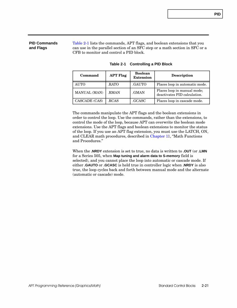
PID
Standard Control Blocks 2-21APT Programming Reference (Graphics/Math)
Table 2-1 lists the commands, APT flags, and boolean extensions that youcan use in the parallel section of an SFC step or a math section in SFC or aCFB to monitor and control a PID block.
Table 2-1 Controlling a PID Block
Command APT Flag BooleanExtension Description
AUTO .RATO .GAUTO Places loop in automatic mode.
MANUAL (MAN) .RMAN .GMAN Places loop in manual mode;deactivates PID calculation.
CASCADE (CAS) .RCAS .GCASC Places loop in cascade mode.
The commands manipulate the APT flags and the boolean extensions inorder to control the loop. Use the commands, rather than the extensions, tocontrol the mode of the loop, because APT can overwrite the boolean modeextensions. Use the APT flags and boolean extensions to monitor the statusof the loop. If you use an APT flag extension, you must use the LATCH, ON,and CLEAR math procedures, described in Chapter 11, “Math Functionsand Procedures.”
When the .NRDY extension is set to true, no data is written to .OUT (or .LMNfor a Series 505, when Map tuning and alarm data to S-memory field isselected), and you cannot place the loop into automatic or cascade mode. Ifeither .GAUTO or .GCASC is held true in controller logic when .NRDY is alsotrue, the loop cycles back and forth between manual mode and the alternate(automatic or cascade) mode.
PID Commandsand Flags
PID
Standard Control Blocks2-22 APT Programming Reference (Graphics/Math)
PID Blocks (continued)
In manual mode, the loop computations are not performed, and the controlprogram or operator can manipulate the output directly by writing to the.OUT (output) extension. For Series 505 controllers, you can also write to the.LMN (loop output) extension when Map tuning and alarm data to S-memory isselected (marked with X).
In automatic mode, the loop takes the setpoint from the .SP (setpoint)extension. Loop calculations are then performed, and the controller outputis updated.
In cascade mode, the setpoint is provided by an external source. This sourcecan be the output of another CFB, a declared real variable, or the outputfrom another PID block.
If you want to connect the output of another loop to the setpoint, selectCASCADED in the Setpoint Source field of the form. In this case, forSeries 505, the setpoint is taken from the scaled integer output (0 to 32000)from the PID source block. For S5, the setpoint is taken from the normalizedoutput (0--1) of the PID source block and is scaled to the engineering units ofthe PV of the cascaded loop.
In order to put a loop in cascade mode, you must follow this sequence.
1. Set the source (master) loop’s output to the desired value (the setpointfor the slave loop).
2. Put the cascade (slave) loop in cascade mode.
3. Put the source (master) loop in automatic mode.
The master loop then feeds its output to the slave loop’s setpoint. If a slaveloop is switched out of cascade, then all of its master loops are placed inmanual. A request to place a master loop in auto or cascade is denied unlessthe slave loop is in cascade.
If the setpoint source is any other real output, select COMPUTED in theSetpoint Source field of the form. In this case, the setpoint is taken from thevariable that you entered in the form.
If the setpoint source is not configured as CASCADED or COMPUTED, youcannot use the CASCADE command.
You cannot edit the Setpoint Source field if you have already marked thePID block for OSx tag translation.
Loops in ManualMode
Loops in AutomaticMode
Loops in CascadeMode
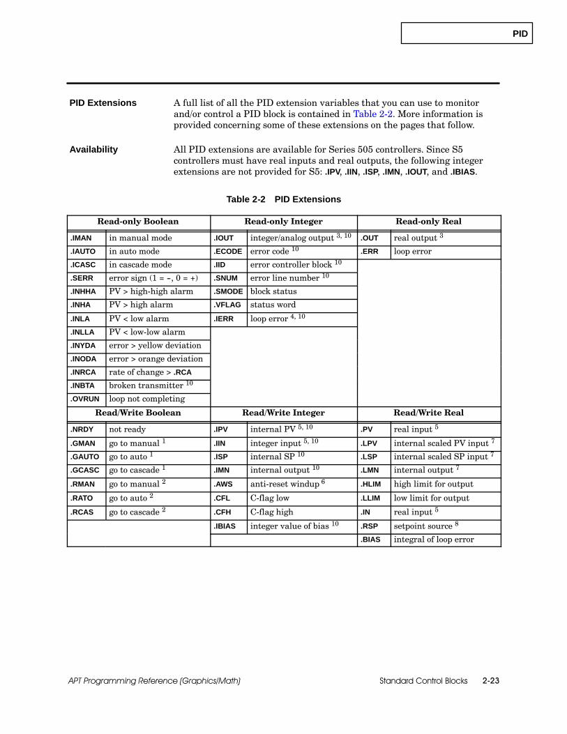
PID
Standard Control Blocks 2-23APT Programming Reference (Graphics/Math)
A full list of all the PID extension variables that you can use to monitorand/or control a PID block is contained in Table 2-2. More information isprovided concerning some of these extensions on the pages that follow.
All PID extensions are available for Series 505 controllers. Since S5controllers must have real inputs and real outputs, the following integerextensions are not provided for S5: .IPV, .IIN, .ISP, .IMN, .IOUT, and .IBIAS.
Table 2-2 PID Extensions
Read-only Boolean Read-only Integer Read-only Real
.IMAN in manual mode .IOUT integer/analog output 3, 10 .OUT real output 3
.IAUTO in auto mode .ECODE error code 10 .ERR loop error
.ICASC in cascade mode .IID error controller block 10
.SERR error sign (1 = --, 0 = +) .SNUM error line number 10
.INHHA PV > high-high alarm .SMODE block status
.INHA PV > high alarm .VFLAG status word
.INLA PV < low alarm .IERR loop error 4, 10
.INLLA PV < low-low alarm
.INYDA error > yellow deviation
.INODA error > orange deviation
.INRCA rate of change > .RCA
.INBTA broken transmitter 10
.OVRUN loop not completing
Read/Write Boolean Read/Write Integer Read/Write Real
.NRDY not ready .IPV internal PV 5, 10 .PV real input 5
.GMAN go to manual 1 .IIN integer input 5, 10 .LPV internal scaled PV input 7
.GAUTO go to auto 1 .ISP internal SP 10 .LSP internal scaled SP input 7
.GCASC go to cascade 1 .IMN internal output 10 .LMN internal output 7
.RMAN go to manual 2 .AWS anti-reset windup 6 .HLIM high limit for output
.RATO go to auto 2 .CFL C-flag low .LLIM low limit for output
.RCAS go to cascade 2 .CFH C-flag high .IN real input 5
.IBIAS integer value of bias 10 .RSP setpoint source 8
.BIAS integral of loop error
PID Extensions
Availability
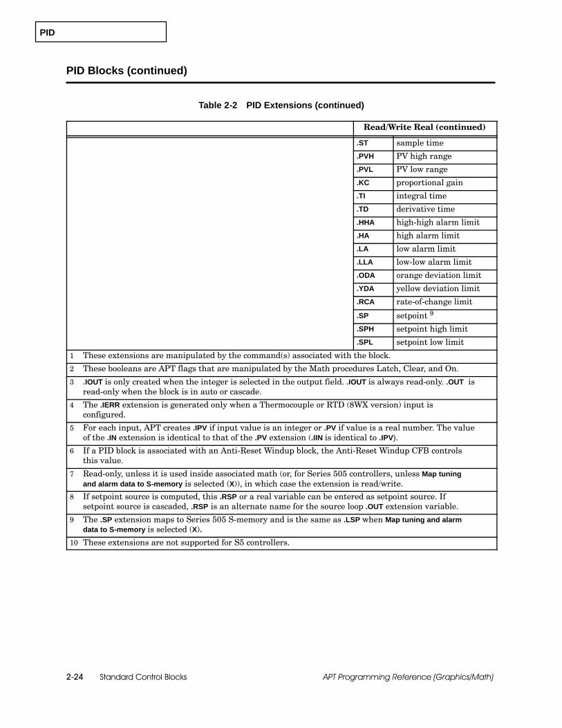
PID
Standard Control Blocks2-24 APT Programming Reference (Graphics/Math)
PID Blocks (continued)
Table 2-2 PID Extensions (continued)
Read/Write Real (continued)
.ST sample time
.PVH PV high range
.PVL PV low range
.KC proportional gain
.TI integral time
.TD derivative time
.HHA high-high alarm limit
.HA high alarm limit
.LA low alarm limit
.LLA low-low alarm limit
.ODA orange deviation limit
.YDA yellow deviation limit
.RCA rate-of-change limit
.SP setpoint 9
.SPH setpoint high limit
.SPL setpoint low limit
1 These extensions are manipulated by the command(s) associated with the block.
2 These booleans are APT flags that are manipulated by the Math procedures Latch, Clear, and On.
3 .IOUT is only created when the integer is selected in the output field. .IOUT is always read-only. .OUT isread-only when the block is in auto or cascade.
4 The .IERR extension is generated only when a Thermocouple or RTD (8WX version) input isconfigured.
5 For each input, APT creates .IPV if input value is an integer or .PV if value is a real number. The valueof the .IN extension is identical to that of the .PV extension (.IIN is identical to .IPV).
6 If a PID block is associated with an Anti-Reset Windup block, the Anti-Reset Windup CFB controlsthis value.
7 Read-only, unless it is used inside associated math (or, for Series 505 controllers, unless Map tuningand alarm data to S-memory is selected (X)), in which case the extension is read/write.
8 If setpoint source is computed, this .RSP or a real variable can be entered as setpoint source. Ifsetpoint source is cascaded, .RSP is an alternate name for the source loop .OUT extension variable.
9 The .SP extension maps to Series 505 S-memory and is the same as .LSP when Map tuning and alarmdata to S-memory is selected (X).
10 These extensions are not supported for S5 controllers.
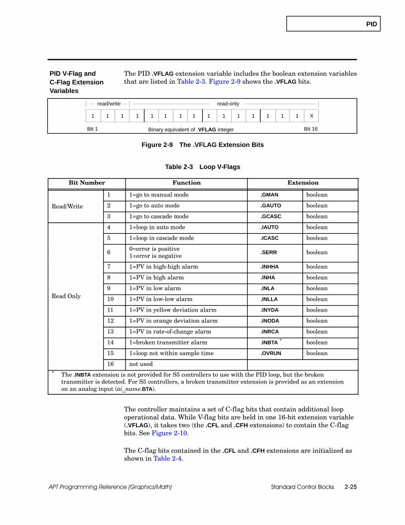
PID
Standard Control Blocks 2-25APT Programming Reference (Graphics/Math)
The PID .VFLAG extension variable includes the boolean extension variablesthat are listed in Table 2-3. Figure 2-9 shows the .VFLAG bits.
Binary equivalent of .VFLAG integerBit 1 Bit 16
read/write read-only
1 1 1 1 1 1 1 1 1 1 1 1 1 1 1 X
Figure 2-9 The .VFLAG Extension Bits
Table 2-3 Loop V-Flags
Bit Number Function Extension
1 1=go to manual mode .GMAN boolean
Read/Write 2 1=go to auto mode .GAUTO boolean
3 1=go to cascade mode .GCASC boolean
4 1=loop in auto mode .IAUTO boolean
5 1=loop in cascade mode .ICASC boolean
6 0=error is positive1=error is negative
.SERR boolean
7 1=PV in high-high alarm .INHHA boolean
8 1=PV in high alarm .INHA boolean
R d O l9 1=PV in low alarm .INLA boolean
Read Only 10 1=PV in low-low alarm .INLLA boolean
11 1=PV in yellow deviation alarm .INYDA boolean
12 1=PV in orange deviation alarm .INODA boolean
13 1=PV in rate-of-change alarm .INRCA boolean
14 1=broken transmitter alarm .INBTA * boolean
15 1=loop not within sample time .OVRUN boolean
16 not used* The .INBTA extension is not provided for S5 controllers to use with the PID loop, but the broken
transmitter is detected. For S5 controllers, a broken transmitter extension is provided as an extensionon an analog input (ai_name.BTA).
The controller maintains a set of C-flag bits that contain additional loopoperational data. While V-flag bits are held in one 16-bit extension variable(.VFLAG), it takes two (the .CFL and .CFH extensions) to contain the C-flagbits. See Figure 2-10.
The C-flag bits contained in the .CFL and .CFH extensions are initialized asshown in Table 2-4.
PID V-Flag andC-Flag ExtensionVariables

PID
Standard Control Blocks2-26 APT Programming Reference (Graphics/Math)
PID Blocks (continued)
Binary equivalent of CFLAGBit 1 Bit 32
1 1 1 1 1 1 1 1 1 1 1 1 1 1 1 1 1 1 1 1 1 1 1 1 1 1 1 1 1 1 1 1
.CFH .CFL
Figure 2-10 The .CFH and .CFL Extension Bits
Table 2-4 Loop C-Flags
Bit Number Function Source
1 0=PV scale 0% offset (unipolar only)1=PV scale 20% offset (unipolar only) I/O Table
2 1=take square root of PV I/O Table
3 1=monitor high/low alarms PID form
4 1=monitor high-high/low-low alarms PID form
5 1=monitor yellow/orange deviations PID form
6 1=monitor rate-of-change alarm PID form
7 1=monitor broken transmitter alarm PID form
8 0=position algorithm1=velocity algorithm PID form
9 0=direct acting1=reverse acting PID form
10 1=control based on error squared PID form
11 1=control based on error deadband PID form
12 1=auto-mode lock set to 0
13 1=cascade-mode lock set to 0
14 1=setpoint lock set to 0
15 0=output scale 0% offset (unipolar only)1=output scale 20% offset (unipolar only) I/O Table
16 1=special function on process variable set to 1
17 1=special function on setpoint set to 1
18 1=freeze bias when output is out of range PID form
19 1=ramp/soak on setpoint set to 0
20 0=output is unipolar1=output is bipolar I/O Table
21 0=PV is unipolar1=PV is bipolar I/O Table
22 1= do derivative gain limiting PID form
23--32 For Series 505, these are used to holdSFPGM number if bit 16 or bit 17 = 1 internal

PID
Standard Control Blocks 2-27APT Programming Reference (Graphics/Math)
The boolean extensions .IMAN (in manual), .IAUTO (in automatic), and .ICASC(in cascade) indicate the internal state of the loop. These bits do not,however, indicate whether the loop computations have completedinitialization.
The .SMODE (status mode) extension provides information about the loopstatus. During loop operation, .SMODE can assume any one of the followingseven integer values.
0: The program has just been downloaded into the controller, but thecontroller has not been switched to run mode.
1: The loop has just transitioned into manual mode from eitherautomatic or cascade; or the loop has just transitioned into manualmode when the controller has just switched to run mode after aprogram download.
2: The loop is in manual mode and has been in this mode for at leastone operation of the loop calculations, or for two seconds, whichever isless.
3: The loop has just transitioned into automatic mode from eithermanual or cascade, and the .SP (setpoint) and .LSP (loop setpoint)extensions have been initialized to the current value of the processvariable. This makes the loop error equal to zero; the loop output doesnot change to provide a bumpless transfer.
4: The loop is in automatic mode and has been in this mode for atleast one operation of the loop calculations. Normal controlcomputations based on the setpoint and process variable are beingperformed.
5: The loop has just transitioned into cascade mode, and setpointinitialization is complete with a bumpless transfer to the .RSPextension.
6: The loop is in the remote or cascaded setpoint mode and has beenin this mode for at least one operation of the loop calculations, andnormal loop computations are being performed on the .RSP extension.
NOTE: Wait until .SMODE equals 3, 4, 5, or 6 before you change the loopsetpoint from an SFC step, math, debug, or OSx; otherwise, the loop mayoverwrite the value with the process variable. To determine loop status,always check the value of the .SMODE extension, not the value of .IMAN,.IAUTO, or .ICASC. The loop always changes mode before APT finishes thecalculation.
Loop StatusExtensions
PID
Standard Control Blocks2-28 APT Programming Reference (Graphics/Math)
PID Blocks (continued)
The .AWS extension defines the anti-reset windup status and can have anyone of the following values during operation of the loop:
0: The output is within the constraints defined by .HLIM (high limit)and .LLIM (low limit) extensions.
1: The output is constrained at the low limit; if the loop tries todecrease the output by decreasing the bias, the output does not change.The output and bias may increase.
2: The output is constrained at the high limit; if the loop tries toincrease the output by increasing the bias, the output does not change.The output and bias may decrease.
3: The block is no longer integrating, and the loop does not have acontrol path to the controlled variable. The output may still change ifthe process variable changes and gain > 0.
If you use external reset windup protection (See “Other Control Blocks”Chapter 9), or if you select Limit output between 0% and 100%, the .AWSextension indicates the status of the loop. However, you can write a 3 to the.AWS extension at any time to freeze the integral mode. Any other value inthe .AWS extension resumes the integral mode.
Reset WindupProtection and the.AWS Extension
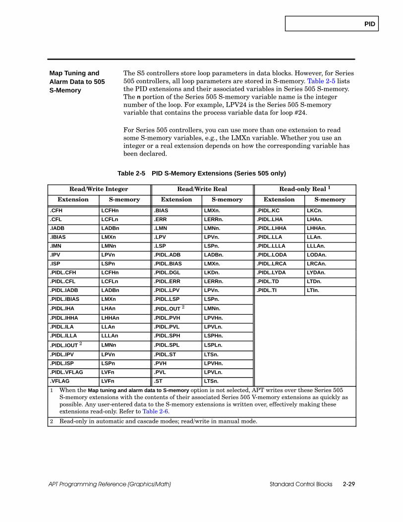
PID
Standard Control Blocks 2-29APT Programming Reference (Graphics/Math)
The S5 controllers store loop parameters in data blocks. However, for Series505 controllers, all loop parameters are stored in S-memory. Table 2-5 liststhe PID extensions and their associated variables in Series 505 S-memory.The n portion of the Series 505 S-memory variable name is the integernumber of the loop. For example, LPV24 is the Series 505 S-memoryvariable that contains the process variable data for loop #24.
For Series 505 controllers, you can use more than one extension to readsome S-memory variables, e.g., the LMXn variable. Whether you use aninteger or a real extension depends on how the corresponding variable hasbeen declared.
Table 2-5 PID S-Memory Extensions (Series 505 only)
Read/Write Integer Read/Write Real Read-only Real 1
Extension S-memory Extension S-memory Extension S-memory
.CFH LCFHn .BIAS LMXn. .PIDL.KC LKCn.
.CFL LCFLn .ERR LERRn. .PIDL.LHA LHAn.
.IADB LADBn .LMN LMNn. .PIDL.LHHA LHHAn.
.IBIAS LMXn .LPV LPVn. .PIDL.LLA LLAn.
.IMN LMNn .LSP LSPn. .PIDL.LLLA LLLAn.
.IPV LPVn .PIDL.ADB LADBn. .PIDL.LODA LODAn.
.ISP LSPn .PIDL.BIAS LMXn. .PIDL.LRCA LRCAn.
.PIDL.CFH LCFHn .PIDL.DGL LKDn. .PIDL.LYDA LYDAn.
.PIDL.CFL LCFLn .PIDL.ERR LERRn. .PIDL.TD LTDn.
.PIDL.IADB LADBn .PIDL.LPV LPVn. .PIDL.TI LTIn.
.PIDL.IBIAS LMXn .PIDL.LSP LSPn.
.PIDL.IHA LHAn .PIDL.OUT 2 LMNn.
.PIDL.IHHA LHHAn .PIDL.PVH LPVHn.
.PIDL.ILA LLAn .PIDL.PVL LPVLn.
.PIDL.ILLA LLLAn .PIDL.SPH LSPHn.
.PIDL.IOUT 2 LMNn .PIDL.SPL LSPLn.
.PIDL.IPV LPVn .PIDL.ST LTSn.
.PIDL.ISP LSPn .PVH LPVHn.
.PIDL.VFLAG LVFn .PVL LPVLn.
.VFLAG LVFn .ST LTSn.
1 When the Map tuning and alarm data to S-memory option is not selected, APT writes over these Series 505S-memory extensions with the contents of their associated Series 505 V-memory extensions as quickly aspossible. Any user-entered data to the S-memory extensions is written over, effectively making theseextensions read-only. Refer to Table 2-6.
2 Read-only in automatic and cascade modes; read/write in manual mode.
Map Tuning andAlarm Data to 505S-Memory

PID
Standard Control Blocks2-30 APT Programming Reference (Graphics/Math)
PID Blocks (continued)
When the Map tuning and alarm data to S-memory option is not selected for aSeries 505 controller, APT maps the loop tuning parameters and alarm datato V-memory. APT also maps the .SP (setpoint) and .OUT (output). Table 2-6lists the PID extensions in Series 505 V-memory that APT copies. APTwrites over these Series 505 S-memory extensions with the contents of theirassociated V-memory extensions as quickly as possible. Any user-entereddata to the Series 505 S-memory extensions is written over, effectivelymaking S-memory extensions read-only.
When the Map tuning and alarm data to S-memory option is selected for aSeries 505 controller, APT uses the loop tuning parameters and alarm datafor that loop directly from S-memory. Using this option can save twelveV-memory locations per loop and the time required to move the data fromV-memory to S-memory. This selection reduces CPU loading and allowsnon-OSx operator interfaces (such as CVU and the loop access module) toreadily interact with the loop. You can use this feature by entering X in theMap tuning and alarm data to S-memory field of the PID form. This optionmakes the extensions, listed in Table 2-6, operate as read/write Series 505S-memory locations, and causes the .SP extension to map to S-memory. Mostof the time this option should be selected (X).
Table 2-6 PID V-Memory Extensions Copied toS-Memory Extensions (Series 505 only)
V-memoryExtension
S-memoryExtension
V-memoryExtension
S-memoryExtension
.KC .PIDL.KC .LA .PIDL.LA
.TI .PIDL.TI .LLA .PIDL.LLA
.TD .PIDL.TD .ODA .PIDL.ODA
.HA .PIDL.HA .YDA .PIDL.YDA
.HHA .PIDL.HHA .RCA .PIDL.RCA
.SP .LSP .OUT .PIDL.OUT
When you have an analog output that requires the energized closed(air-to-close) output option for a Series 505 controller, then the Map tuningand alarm data to S-memory option is not selected. In this manner, the .OUTcan be manipulated before it is sent to the field because APT will use the.OUT extension in Series 505 V-memory to invert the signal. For air-to-closeon analog output, .LMN goes from zero to one for the associated math onoutput and .OUT goes from one to zero after the associated math on output iscomplete.
You cannot edit the Map tuning and alarm data to S-memory field if you havealready marked the PID block for OSx tag translation.
PID
Standard Control Blocks 2-31APT Programming Reference (Graphics/Math)
For Series 505 controllers, the status of Series 500/Series 505 RTD andThermocouple modules is reported by the .IERR and .INBTA extensions. ForS5 controllers, the status of RTD and Thermocouple is reported in the AIextension (.BTA) for the RTD or Thermocouple, not in the loop extensions.
For Series 505, the .INBTA extension becomes true when the associatedmodule has an error, for example, a broken transmitter.
For Series 505, the .IERR extension normally equals the internally scaled PVof the the RTD or thermocouple input. The .IERR extension contains themodule error code when:
The module has an error and,
You specified the RTD or Thermocouple name without an extension inthe process variable field (all standard or advanced blocks except for theratio station).
Refer to the Series 500/505 RTD or Thermocouple user manual for adefinition of the error code. If you specified the RTD or Thermocouple namewith the .RAW extension, then APT does not execute the .IERR logic.
RTD andThermocoupleModule Extensionsfor Series 505
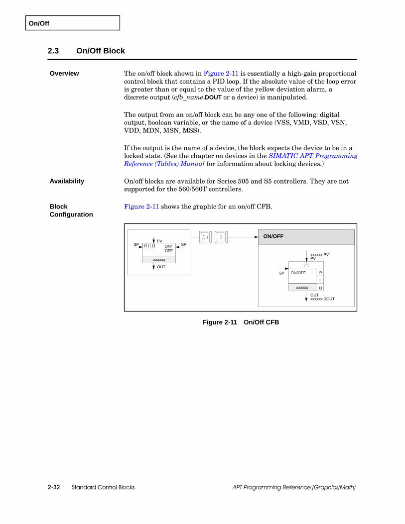
On/Off
Standard Control Blocks2-32 APT Programming Reference (Graphics/Math)
2.3 On/Off Block
The on/off block shown in Figure 2-11 is essentially a high-gain proportionalcontrol block that contains a PID loop. If the absolute value of the loop erroris greater than or equal to the value of the yellow deviation alarm, adiscrete output (cfb_name.DOUT or a device) is manipulated.
The output from an on/off block can be any one of the following: digitaloutput, boolean variable, or the name of a device (VSS, VMD, VSD, VSN,VDD, MDN, MSN, MSS).
If the output is the name of a device, the block expects the device to be in alocked state. (See the chapter on devices in the SIMATIC APT ProgrammingReference (Tables) Manual for information about locking devices.)
On/off blocks are available for Series 505 and S5 controllers. They are notsupported for the 560/560T controllers.
Figure 2-11 shows the graphic for an on/off CFB.
OUT
SP
ON/OFF
xxxxxx.DOUT
xxxxxx.PVPV
P
I
D
OUT
PVSPSP
xxxxxx
xxxxxx
ON/OFF
P I D ON/OFF
Figure 2-11 On/Off CFB
Overview
Availability
BlockConfiguration
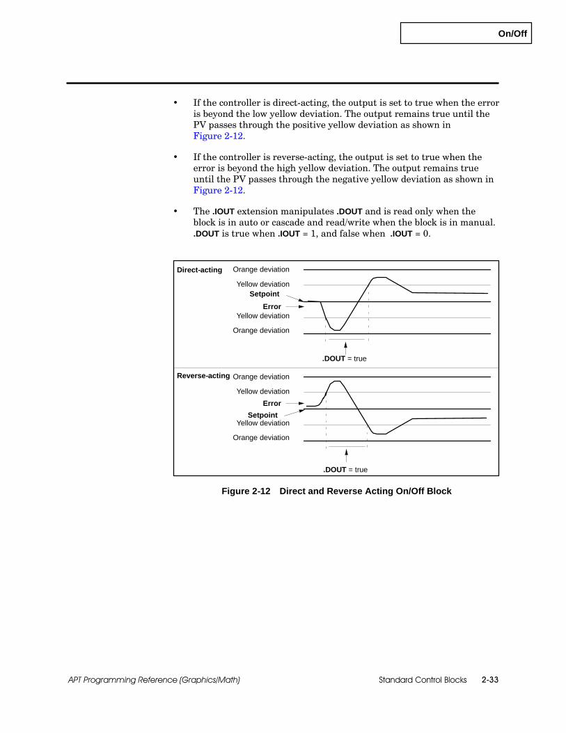
On/Off
Standard Control Blocks 2-33APT Programming Reference (Graphics/Math)
If the controller is direct-acting, the output is set to true when the erroris beyond the low yellow deviation. The output remains true until thePV passes through the positive yellow deviation as shown inFigure 2-12.
If the controller is reverse-acting, the output is set to true when theerror is beyond the high yellow deviation. The output remains trueuntil the PV passes through the negative yellow deviation as shown inFigure 2-12.
The .IOUT extension manipulates .DOUT and is read only when theblock is in auto or cascade and read/write when the block is in manual..DOUT is true when .IOUT = 1, and false when .IOUT = 0.
Yellow deviation
Yellow deviation
Orange deviation
Orange deviation
Error
Setpoint
Direct-acting
Reverse-acting
.DOUT = true
Yellow deviation
Yellow deviation
Orange deviation
Orange deviation
Error
Setpoint
.DOUT = true
Figure 2-12 Direct and Reverse Acting On/Off Block
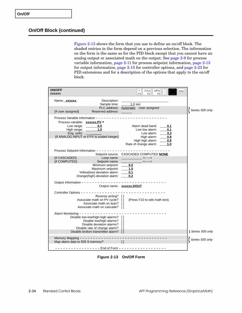
On/Off
Standard Control Blocks2-34 APT Programming Reference (Graphics/Math)
On/Off Block (continued)
Figure 2-13 shows the form that you use to define an on/off block. Theshaded entries in the form depend on a previous selection. The informationon the form is the same as for the PID block except that you cannot have ananalog output or associated math on the output. See page 2-9 for processvariable information, page 2-11 for process setpoint information, page 2-13for output information, page 2-15 for controller options, and page 2-23 forPID extensions and for a description of the options that apply to the on/offblock.
ON/OFFxxxxxx
?F1
ESCCTLsF2
OPTsF3
} Series 505 only
Name: xxxxxx Description:Sample time: 1.0 secPLC address: Automatic User assigned
{If user assigned} Reserved address: ______
Process Variable Information -- -- -- -- -- -- -- -- -- -- -- -- -- -- -- -- -- -- -- -- -- -- -- -- -- -- --Process variable: xxxxxx.PV S
Low range: 0.0 Alarm dead band: 0.1High range: 1.0 Low low alarm: 0.1Eng. units: ______ Low alarm: 0.2
High alarm: 0.8High high alarm: 0.9
Rate of change alarm: 1.0
Process Setpoint Information -- -- -- -- -- -- -- -- -- -- -- -- -- -- -- -- -- -- -- -- -- -- -- -- -- -- -- --Setpoint source: CASCADED COMPUTED NONE
{if CASCADED} Loop name: <------>{if COMPUTED} Setpoint name: <------>
Minimum setpoint: 0.0Maximum setpoint: 1.0
Yellow(low) deviation alarm: 0.1Orange(high) deviation alarm: 0.2
Output Information -- -- -- -- -- -- -- -- -- -- -- -- -- -- -- -- -- -- -- -- -- -- -- -- -- -- -- -- -- -- -- --Output name: xxxxxx.DOUT
Controller Options -- -- -- -- -- -- -- -- -- -- -- -- -- -- -- -- -- -- -- -- -- -- -- -- -- -- -- -- -- -- -- --Reverse acting? [ ]
Associate math on PV cycle? [ ] (Press F10 to edit math text)Associate math on auto? [ ]
Associate math on cascade? [ ]
Alarm Monitoring -- -- -- -- -- -- -- -- -- -- -- -- -- -- -- -- -- -- -- -- -- -- -- -- -- -- -- -- -- -- -- -- --Disable low-low/high-high alarms? [ ]
Disable low/high alarms? [ ]Disable deviation alarms? [ ]
Disable rate of change alarm? [ ]Disable broken transmitter alarm? [ ]
Memory Mapping -- -- -- -- -- -- -- -- -- -- -- -- -- -- -- -- -- -- -- -- -- -- -- -- -- -- -- -- -- -- -- -- --Map alarm data to 505 S-memory? [ ]
-- -- -- -- -- -- -- -- -- -- -- -- -- -- -- -- -- End of Form -- -- -- -- -- -- -- -- -- -- -- -- -- -- -- -- -- --
{if ANALOG INPUT or if PV is scaled integer}
Series 505 only
Series 505 only
Figure 2-13 On/Off Form

On/Off
Standard Control Blocks 2-35APT Programming Reference (Graphics/Math)
Table 2-7 lists the commands that determine the mode of operation for theon/off block: MANUAL (MAN), AUTO, and CASCADE (CAS). Thesecommands operate the same way that they do for the PID block. Seepage 2-21 for PID commands.
Table 2-7 On/Off Commands
Command Description
AUTOPlaces loop in automatic mode and gets setpoint fromcfb_name.SP
MANUAL (MAN)Places loop in manual mode; deactivates PID calculation; tomanipulate output: modify .IOUT = 1 for .DOUT = true, and.IOUT = 0 for .DOUT = false
CASCADE (CAS)Places loop into cascade mode; to change setpoint, modifythe remote source (output from connected loop, block, orreal variable).
On/Off Commands
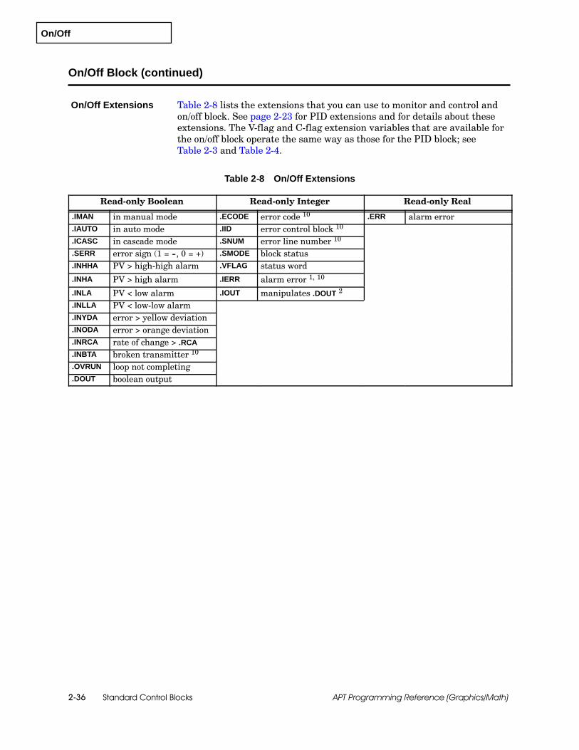
On/Off
Standard Control Blocks2-36 APT Programming Reference (Graphics/Math)
On/Off Block (continued)
Table 2-8 lists the extensions that you can use to monitor and control andon/off block. See page 2-23 for PID extensions and for details about theseextensions. The V-flag and C-flag extension variables that are available forthe on/off block operate the same way as those for the PID block; seeTable 2-3 and Table 2-4.
Table 2-8 On/Off Extensions
Read-only Boolean Read-only Integer Read-only Real
.IMAN in manual mode .ECODE error code 10 .ERR alarm error
.IAUTO in auto mode .IID error control block 10
.ICASC in cascade mode .SNUM error line number 10
.SERR error sign (1 = --, 0 = +) .SMODE block status
.INHHA PV > high-high alarm .VFLAG status word
.INHA PV > high alarm .IERR alarm error 1, 10
.INLA PV < low alarm .IOUT manipulates .DOUT 2
.INLLA PV < low-low alarm
.INYDA error > yellow deviation
.INODA error > orange deviation
.INRCA rate of change > .RCA
.INBTA broken transmitter 10
.OVRUN loop not completing
.DOUT boolean output
On/Off Extensions

On/Off
Standard Control Blocks 2-37APT Programming Reference (Graphics/Math)
Table 2-8 On/Off Extensions (continued)
Read/Write Boolean Read/Write Integer Read/Write Real
.NRDY not ready .IPV internal PV 5, 10 .PV real input 5
.GMAN go to manual 3 .IIN integer input 5, 10 .LPV scaled PV input 6
.GAUTO go to auto 3 .ISP internal SP 10 .LSP scaled SP input 6
.GCASC go to cascade 3 .IMN internal output 10 .LMN internal output 7
.RMAN go to manual 4 .CFL C-flag low .RSP setpoint source 8
.RATO go to auto 4 .CFH C-flag high .ST sample time
.RCAS go cascade 4 .IBIAS integer value of bias 10 .IN real input 5
.PVH PV high range
.PVL PV low range
.HHA high-high alarm limit
.HA high alarm limit
.LA low alarm limit
.LLA low-low alarm limit
.ODA orange deviation limit
.YDA yellow deviation limit
.RCA rate-of-change limit
.SP setpoint 9
.SPH setpoint high limit
.SPL setpoint low limit
.BIAS integral of loop error1 The .IERR extension is generated only when a Series 505 Thermocouple or RTD (8WX version) input is
configured.2 The .IOUT extension manipulates .DOUT and is read only when the block is in auto or cascade and
read/write when the block is in manual. .DOUT is true when .IOUT = 1, and false when .IOUT = 0.3 These extensions are manipulated by the command(s) associated with the block.4 These booleans are APT flags that are manipulated by the Math procedures Latch, Clear, and On.5 For each input, APT creates .IIN if input value is an integer or .IN if value is a real number. The value
of the .PV extension is identical to that of the .IN extension (.IIN is identical to .IPV).
6 Read-only, unless it is used inside associated math (or, for Series 505 controllers, unless Map tuningand alarm data to S-memory is selected (X)), in which case the extension is read/write.
7 .LMN has no effect on .DOUT
8 If setpoint source is computed, this .RSP or a real variable can be entered as setpoint source. Ifsetpoint source is cascaded, .RSP is an alternate name for the source loop .OUT extension variable.
9 The .SP extension maps to Series 505 S-memory and is the same as .LSP when Map tuning and alarmdata to S-memory is selected (X).
10 These extensions are not supported for S5 controllers.

Analog Alarm
Standard Control Blocks2-38 APT Programming Reference (Graphics/Math)
2.4 Analog Alarm Block
The analog alarm block offers the same types of alarms as the otherstandard control blocks. You can use it to monitor a process variable, butnot to control it. (The analog alarm block does not have an output nor doesit have tuning parameters.) If you select an analog alarm, you use thehigh/low alarm capability of the loops and you are also able to set a setpointand use the orange and yellow deviations from the setpoint as alarms.
You can select a setpoint source of computed, value, or internal.
If you select a setpoint source of computed, the setpoint is provided byan external source. This source can be the output of another CFB, adeclared real variable, or the output from another PID block.
If you select a setpoint source of value, you specify the actual value ofthe setpoint when you define the block. This value can be changed onlyby editing the CFB form.
If you select a setpoint source of internal, the value of the setpoint isdetermined by the value that you write to the cfb_name.SP extension.
Figure 2-14 shows the form that you use to define an analog alarm block.The shaded entries in the form depend on a previous selection. Theinformation on the form is the same as for the PID block, except that youhave only one associated math section and it is always enabled. Seepage 2-9 for process variable information, and page 2-11 for processsetpoint information and for a description of the options that apply to theanalog alarm block.
The user-assigned address for an analog alarm is %AALMn.
Analog alarm blocks are available for both Series 505 and S5 controllers;however, for the Series 505, the analog alarm block is part of the firmware,while for the S5 the block has been implemented through code.Consequently, the S5 analog alarm block has several distinctive features:
The Series 505 S-memory mapping feature is not supported for S5.
The process variable for S5 controllers must be a real number, forinstance, a scaled analog input.
The PLC Reserved Address feature is not supported for S5.
The broken transmitter signal is an AI extension and not an alarmextension for S5.
Overview
Availability
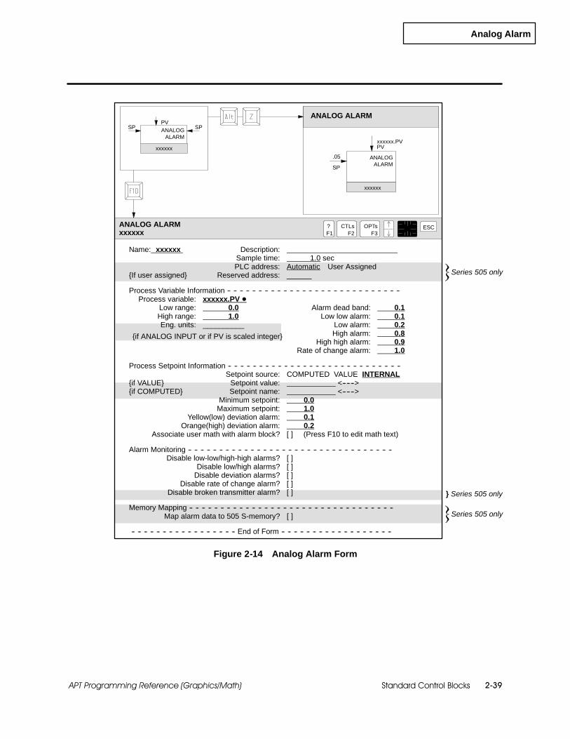
Analog Alarm
Standard Control Blocks 2-39APT Programming Reference (Graphics/Math)
SP
ANALOG ALARM
xxxxxx.PVPV
ANALOG ALARMxxxxxx
?F1
ESCCTLsF2
OPTsF3
PVSPSP
xxxxxx
xxxxxx
ANALOGALARM
.05 ANALOGALARM
} Series 505 only
Name: xxxxxx Description:Sample time: 1.0 secPLC address: Automatic User Assigned
{If user assigned} Reserved address: ______
Process Variable Information -- -- -- -- -- -- -- -- -- -- -- -- -- -- -- -- -- -- -- -- -- -- -- -- -- -- -- --Process variable: xxxxxx.PV D
Low range: 0.0 Alarm dead band: 0.1High range: 1.0 Low low alarm: 0.1Eng. units: __________ Low alarm: 0.2
High alarm: 0.8High high alarm: 0.9
Rate of change alarm: 1.0
Process Setpoint Information -- -- -- -- -- -- -- -- -- -- -- -- -- -- -- -- -- -- -- -- -- -- -- -- -- -- -- --Setpoint source: COMPUTED VALUE INTERNAL
{if VALUE} Setpoint value: <------>{if COMPUTED} Setpoint name: <------>
Minimum setpoint: 0.0Maximum setpoint: 1.0
Yellow(low) deviation alarm: 0.1Orange(high) deviation alarm: 0.2
Associate user math with alarm block? [ ] (Press F10 to edit math text)
Alarm Monitoring -- -- -- -- -- -- -- -- -- -- -- -- -- -- -- -- -- -- -- -- -- -- -- -- -- -- -- -- -- -- -- -- --Disable low-low/high-high alarms? [ ]
Disable low/high alarms? [ ]Disable deviation alarms? [ ]
Disable rate of change alarm? [ ]Disable broken transmitter alarm? [ ]
Memory Mapping -- -- -- -- -- -- -- -- -- -- -- -- -- -- -- -- -- -- -- -- -- -- -- -- -- -- -- -- -- -- -- -- --Map alarm data to 505 S-memory? [ ]
-- -- -- -- -- -- -- -- -- -- -- -- -- -- -- -- -- End of Form -- -- -- -- -- -- -- -- -- -- -- -- -- -- -- -- -- --
{if ANALOG INPUT or if PV is scaled integer}
Series 505 only
Series 505 only
Figure 2-14 Analog Alarm Form

Analog Alarm
Standard Control Blocks2-40 APT Programming Reference (Graphics/Math)
Analog Alarm Block (continued)
Table 2-9 lists the commands that determine the mode of operation for theanalog alarm block: ENABLE (ENA) and DISABLE (DIS). Note thatassociated math is always executed.
Table 2-9 Analog Alarm Commands
Command Description
ENABLE (ENA) Turns on, or activates, the alarming.
DISABLE (DIS) Turns off, or deactivates, the alarming.
Table 2-10 lists the extensions that you can use to monitor and control theanalog alarm block.
The .SMODE extension defines the current status of the block and differsfrom the .SMODE extension for the PID.
0: The deviation alarms are not executing.
1: The deviation alarms are executing. Transitions can check for a 1 in the.SMODE variable to determine that the setpoint has been updated.
The internal representation of the scaled process variable is stored in the.APV extension variable. The setpoint is stored in the .ASP variable. If youwant to manipulate either the process variable or the setpoint in associatedmath, you use these variables.
See page 2-23 for details about the other PID extensions.
Table 2-10 Analog Alarm Extensions
Read-only Boolean Read-only Integer Read-only Real
.DSABL disabled .ECODE error code 1 .ERR alarm error
.INHHA PV > high-high alarm .IID error controller block 1
.INHA PV > high alarm .SNUM error line number 1
.INLA PV < low alarm .SMODE block status
.INLLA PV < low-low alarm .VFLAG status word
.INYDA error > yellow deviation .IERR alarm error 1, 2
.INODA error > orange deviation
.INRCA rate of change > .RCA
.INBTA broken transmitter 1
.OVRUN alarm not completing
Analog AlarmCommands
Analog AlarmExtensions

Analog Alarm
Standard Control Blocks 2-41APT Programming Reference (Graphics/Math)
Table 2--10 Analog Alarm Extensions (continued)
Read/Write Boolean Read/Write Integer Read/Write Real
.ENABL enable 3 .IPV internal PV 1, 5 .PV real input 5
.NRDY not ready .IIN integer input 1, 5 .APV internal PV input 6
.REN request enable 4 .ISP internal SP 1 .ASP internal SP input 6
.RDIS request disable 4 .CFL C-flag low .RSP setpoint source 7
.CFH C-flag high .ST sample time
.IN real input 5
.PVH PV high range
.PVL PV low range
.HHA high-high alarm
.HA high alarm limit
.LA low alarm limit
.LLA low-low alarm limit
.ADB alarm deadband
.ODA orange deviation limit
.YDA yellow deviation limit
.RCA rate-of-change limit
.SP setpoint 8
.SPH setpoint high limit
.SPL setpoint low limit
1 These extensions are not supported for S5 controllers.
2 The .IERR extension is generated only when a Series 505 Thermocouple or RTD input (8WX version) isconfigured.
3 This extension is manipulated by the command(s) associated with the block.
4 These booleans are APT flags that are manipulated by the Math procedures Latch, Clear, and On.
5 For each input, APT creates .IPV if input value is an integer, or .PV if value is a real number. Thevalue of the extension is identical to that of the .PV extension (.IIN is identical to .IPV).
6 Read-only, unless used inside associated math or Map tuning and alarm data to S-memory selected (X).
7 If setpoint source is computed, this .RSP or a real variable can be entered as setpoint source.
8 The .SP extension maps to Series 505 S-memory and is the same as .ASP when Map tuning and alarmdata to S-memory is selected (X).

Analog Alarm
Standard Control Blocks2-42 APT Programming Reference (Graphics/Math)
Analog Alarm Block (continued)
The analog alarm .VFLAG extension variable includes the boolean extensionvariables that are listed in Table 2-11. Figure 2-15 shows the .VFLAG bits.The .VFLAG value is updated when the block is enabled.
Binary equivalent of .VFLAG integerBit 1 Bit 16
1 1 1 1 1 1 1 1 1 1 1 1 X X X X
read/write
read-only
Figure 2-15 The .VFLAG Extension Bits
Table 2-11 Analog Alarm V-Flags
Bit Number Function Extension
Read/Write1* 1=enable alarm .ENABL
Read/Write2* 1=disable alarm .DSABL
3 1=PV in high-high alarm .INHHA
4 1=PV in high alarm .INHA
5 1=PV in low alarm .INLA
6 1=PV in low-low alarm .INLLA
7 1=PV in yellow deviation alarm .INYDA
Read Only 8 1=PV in orange deviation alarm .INODAy
9 1=PV in rate-of-change alarm .INRCA
10 1=broken transmitter alarm .INBTA 1
11 1=analog alarm is overrunning .OVRUN
12 1=enabled .ENABL 2
13--16 not used
1 The .INBTA extension is for Series 505 controllers. If you have an S5, use theanalog input .BTA extension.
2 Write a 1 to bits 1 and 2 to enable/disable the alarm. To determine the statusof the alarm, read bit 12. If you attempt to read bits 1 or 2, status is notreturned because these bits are always cleared.
The controller maintains a set of C-flag bits that contain additionaloperational data. While V-flag bits are held in one 16-bit extension variable(.VFLAG), it takes two (the .CFL and .CFH extensions) to contain the C-flagbits. See Figure 2-16.
The .CFL and .CFH extensions are initialized as shown in Table 2-12.
Analog AlarmV-Flag and C-FlagExtensionVariables

Analog Alarm
Standard Control Blocks 2-43APT Programming Reference (Graphics/Math)
.CFH .CFL
Binary equivalent of CFLAGBit 1 Bit 32
1 1 1 1 1 1 1 1 x x x x x x x x x x x x 1 x 1 1 1 1 1 1 1 1 1 1
Figure 2-16 The .CFH and .CFL Extension Bits
Table 2-12 Analog Alarm C-Flags
Bit Number Function Source
1 0=PV scale 0% offset1=PV scale 20% offset I/O Table
2 1=take square root of PV I/O Table
3 1=monitor high/low alarms Analog form
4 1=monitor high-high/low-low alarms Analog form
5 1=monitor yellow/orange deviations Analog form
6 1=monitor rate-of-change alarm Analog form
7 1=monitor broken transmitter alarm Analog form
8 0=local setpoint1=remote setpoint Analog form
9--20 not used
21 0=PV is unipolar1=PV is bipolar I/O Table
22 not used
23--32 For Series 505, these are used to holdSFPGM number if bit 16 or bit 17 = 1 internal
To expand the capability of the analog alarm block, you can append Mathcomputations. For Series 505, the math compiles as SFPGM; for S5,associated math compiles as STL.
You can use the associated math to enable the block usingName.ENABL := true; in the associated math section.
To modify the process variable from within an associated math block,manipulate the .APV extension. To modify the setpoint variable, manipulatethe .ASP extension.
NOTE: The associated math for the analog alarm CFB always executeseven when the block is not enabled.
Associated Math

Analog Alarm
Standard Control Blocks2-44 APT Programming Reference (Graphics/Math)
Analog Alarm Block (continued)
Table 2-13 lists the analog alarm extensions and their associated variablesin Series 505 S-memory. The n portion of the S-memory variable is theinteger number of the analog alarm. For example, APV55 is the S-memoryvariable that contains the process variable data for analog alarm #55.
You can use more than one extension to read some Series 505 S-memoryvariables, e.g., APVn.
Table 2-13 Analog Alarm Series 505 S-Memory Extensions
Read/Write Real Read-only Real 1
Extension S-memory Extension S-memory
.AL_RECORD.ADB AADBn. .AL_RECORD.AHA AHAn.
.AL_RECORD.AERR AERRn. .AL_RECORD.AHHA AHHAn.
.AL_RECORD.PV APVn. .AL_RECORD.ALA ALAn.
.AL_RECORD.PVH APVHn. .AL_RECORD.ALLA ALLAn.
.AL_RECORD.PVL APVLn. .AL_RECORD.AODA AODAn.
.AL_RECORD.SP ASPn. .AL_RECORD.ARCA ARCAn.
.AL_RECORD.SPH ASPHn. .AL_RECORD.AYDA AYDAn.
.AL_RECORD.SPL ASPLn.
.AL_RECORD.ST ATSn.
.APV APVn.
.APVH APVHn.
.APVL APVLn.
.ASP ASPn.
.ERR AERRn.
.PVH APVHn.
.PVL APVLn.
.ST ATSn.
1 For Series 505, when the Map alarm data to S-memory option is not selected,APT writes over these Series 505 S-memory extensions with the contents oftheir associated V-memory extensions as quickly as possible. Any user-entereddata to the S-memory extensions is written over, effectively making theseextensions read-only. Refer to Table 2-14.
S-MemoryVariables(Series 505 only)
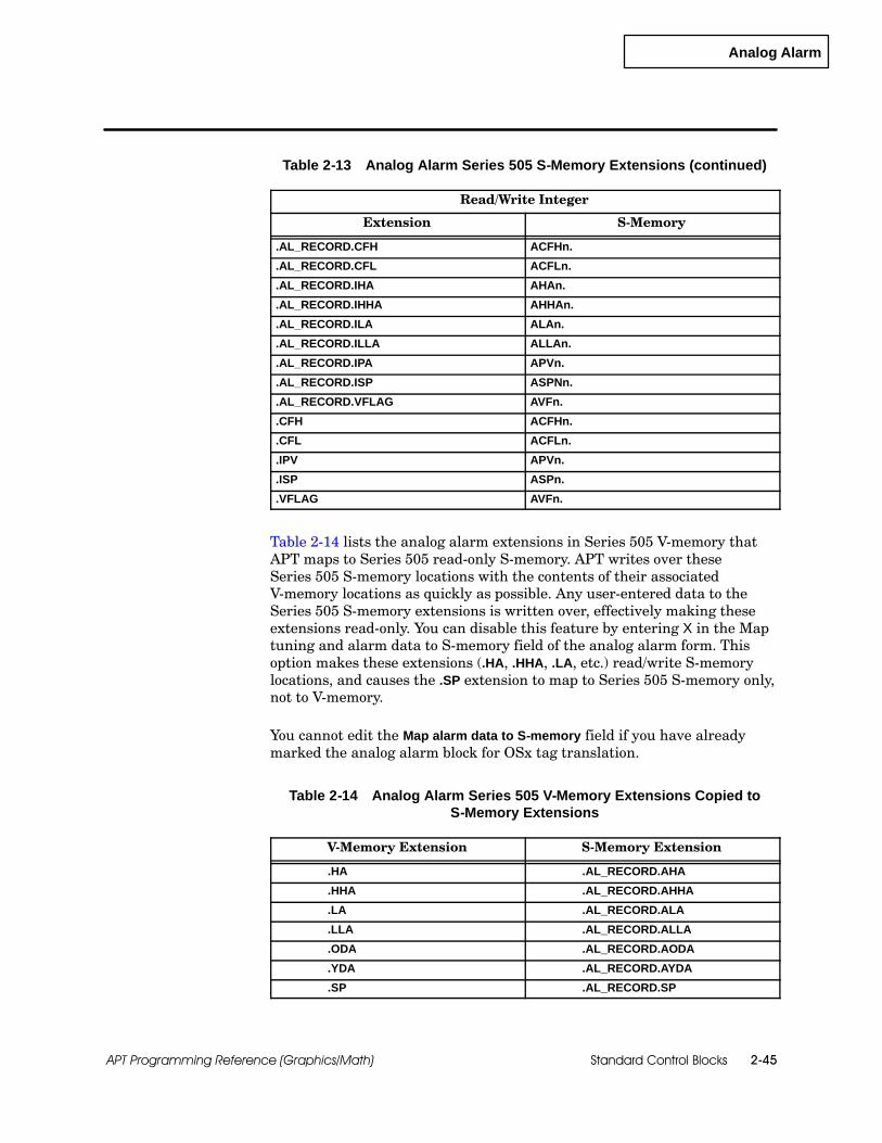
Analog Alarm
Standard Control Blocks 2-45APT Programming Reference (Graphics/Math)
Table 2-13 Analog Alarm Series 505 S-Memory Extensions (continued)
Read/Write Integer
Extension S-Memory
.AL_RECORD.CFH ACFHn.
.AL_RECORD.CFL ACFLn.
.AL_RECORD.IHA AHAn.
.AL_RECORD.IHHA AHHAn.
.AL_RECORD.ILA ALAn.
.AL_RECORD.ILLA ALLAn.
.AL_RECORD.IPA APVn.
.AL_RECORD.ISP ASPNn.
.AL_RECORD.VFLAG AVFn.
.CFH ACFHn.
.CFL ACFLn.
.IPV APVn.
.ISP ASPn.
.VFLAG AVFn.
Table 2-14 lists the analog alarm extensions in Series 505 V-memory thatAPT maps to Series 505 read-only S-memory. APT writes over theseSeries 505 S-memory locations with the contents of their associatedV-memory locations as quickly as possible. Any user-entered data to theSeries 505 S-memory extensions is written over, effectively making theseextensions read-only. You can disable this feature by entering X in the Maptuning and alarm data to S-memory field of the analog alarm form. Thisoption makes these extensions (.HA, .HHA, .LA, etc.) read/write S-memorylocations, and causes the .SP extension to map to Series 505 S-memory only,not to V-memory.
You cannot edit the Map alarm data to S-memory field if you have alreadymarked the analog alarm block for OSx tag translation.
Table 2-14 Analog Alarm Series 505 V-Memory Extensions Copied toS-Memory Extensions
V-Memory Extension S-Memory Extension
.HA .AL_RECORD.AHA
.HHA .AL_RECORD.AHHA
.LA .AL_RECORD.ALA
.LLA .AL_RECORD.ALLA
.ODA .AL_RECORD.AODA
.YDA .AL_RECORD.AYDA
.SP .AL_RECORD.SP


Dynamic Control Blocks 3-1APT Programming Reference (Graphics/Math)
Chapter 3
Dynamic Control Blocks
3.1 Understanding Dynamic Blocks 3-2. . . . . . . . . . . . . . . . . . . . . . . . . . . . . . . . . . . . . . . . . . . . . . . . .Overview 3-2. . . . . . . . . . . . . . . . . . . . . . . . . . . . . . . . . . . . . . . . . . . . . . . . . . . . . . . . . . . . . . . . . . . . . . .Availability 3-2. . . . . . . . . . . . . . . . . . . . . . . . . . . . . . . . . . . . . . . . . . . . . . . . . . . . . . . . . . . . . . . . . . . . . .Enabling and Disabling Blocks 3-3. . . . . . . . . . . . . . . . . . . . . . . . . . . . . . . . . . . . . . . . . . . . . . . . . . . .Initialization 3-4. . . . . . . . . . . . . . . . . . . . . . . . . . . . . . . . . . . . . . . . . . . . . . . . . . . . . . . . . . . . . . . . . . . . .Simulation Equations 3-6. . . . . . . . . . . . . . . . . . . . . . . . . . . . . . . . . . . . . . . . . . . . . . . . . . . . . . . . . . . .
3.2 Second Order Lead Lag 3-7. . . . . . . . . . . . . . . . . . . . . . . . . . . . . . . . . . . . . . . . . . . . . . . . . . . . . . . . .Overview 3-7. . . . . . . . . . . . . . . . . . . . . . . . . . . . . . . . . . . . . . . . . . . . . . . . . . . . . . . . . . . . . . . . . . . . . . .Availability 3-7. . . . . . . . . . . . . . . . . . . . . . . . . . . . . . . . . . . . . . . . . . . . . . . . . . . . . . . . . . . . . . . . . . . . . .Block Configuration 3-8. . . . . . . . . . . . . . . . . . . . . . . . . . . . . . . . . . . . . . . . . . . . . . . . . . . . . . . . . . . . . .Commands and Extensions 3-9. . . . . . . . . . . . . . . . . . . . . . . . . . . . . . . . . . . . . . . . . . . . . . . . . . . . . . .
3.3 Second Order Lag 3-10. . . . . . . . . . . . . . . . . . . . . . . . . . . . . . . . . . . . . . . . . . . . . . . . . . . . . . . . . . . . . .Overview 3-10. . . . . . . . . . . . . . . . . . . . . . . . . . . . . . . . . . . . . . . . . . . . . . . . . . . . . . . . . . . . . . . . . . . . . . .Availability 3-10. . . . . . . . . . . . . . . . . . . . . . . . . . . . . . . . . . . . . . . . . . . . . . . . . . . . . . . . . . . . . . . . . . . . . .Block Configuration 3-11. . . . . . . . . . . . . . . . . . . . . . . . . . . . . . . . . . . . . . . . . . . . . . . . . . . . . . . . . . . . . .Commands and Extensions 3-12. . . . . . . . . . . . . . . . . . . . . . . . . . . . . . . . . . . . . . . . . . . . . . . . . . . . . . .
3.4 First Order Lead Lag 3-13. . . . . . . . . . . . . . . . . . . . . . . . . . . . . . . . . . . . . . . . . . . . . . . . . . . . . . . . . . .Overview 3-13. . . . . . . . . . . . . . . . . . . . . . . . . . . . . . . . . . . . . . . . . . . . . . . . . . . . . . . . . . . . . . . . . . . . . . .Availability 3-14. . . . . . . . . . . . . . . . . . . . . . . . . . . . . . . . . . . . . . . . . . . . . . . . . . . . . . . . . . . . . . . . . . . . . .Block Configuration 3-15. . . . . . . . . . . . . . . . . . . . . . . . . . . . . . . . . . . . . . . . . . . . . . . . . . . . . . . . . . . . . .Commands and Extensions 3-16. . . . . . . . . . . . . . . . . . . . . . . . . . . . . . . . . . . . . . . . . . . . . . . . . . . . . . .
3.5 First Order Lag 3-17. . . . . . . . . . . . . . . . . . . . . . . . . . . . . . . . . . . . . . . . . . . . . . . . . . . . . . . . . . . . . . . . .Overview 3-17. . . . . . . . . . . . . . . . . . . . . . . . . . . . . . . . . . . . . . . . . . . . . . . . . . . . . . . . . . . . . . . . . . . . . . .Availability 3-17. . . . . . . . . . . . . . . . . . . . . . . . . . . . . . . . . . . . . . . . . . . . . . . . . . . . . . . . . . . . . . . . . . . . . .Block Configuration 3-18. . . . . . . . . . . . . . . . . . . . . . . . . . . . . . . . . . . . . . . . . . . . . . . . . . . . . . . . . . . . . .Commands and Extensions 3-19. . . . . . . . . . . . . . . . . . . . . . . . . . . . . . . . . . . . . . . . . . . . . . . . . . . . . . .
3.6 Derivative 3-20. . . . . . . . . . . . . . . . . . . . . . . . . . . . . . . . . . . . . . . . . . . . . . . . . . . . . . . . . . . . . . . . . . . . .Overview 3-20. . . . . . . . . . . . . . . . . . . . . . . . . . . . . . . . . . . . . . . . . . . . . . . . . . . . . . . . . . . . . . . . . . . . . . .Availability 3-20. . . . . . . . . . . . . . . . . . . . . . . . . . . . . . . . . . . . . . . . . . . . . . . . . . . . . . . . . . . . . . . . . . . . . .Block Configuration 3-21. . . . . . . . . . . . . . . . . . . . . . . . . . . . . . . . . . . . . . . . . . . . . . . . . . . . . . . . . . . . . .Commands and Extensions 3-22. . . . . . . . . . . . . . . . . . . . . . . . . . . . . . . . . . . . . . . . . . . . . . . . . . . . . . .
3.7 Dead Time Delay 3-23. . . . . . . . . . . . . . . . . . . . . . . . . . . . . . . . . . . . . . . . . . . . . . . . . . . . . . . . . . . . . . .Overview 3-23. . . . . . . . . . . . . . . . . . . . . . . . . . . . . . . . . . . . . . . . . . . . . . . . . . . . . . . . . . . . . . . . . . . . . . .Availability 3-23. . . . . . . . . . . . . . . . . . . . . . . . . . . . . . . . . . . . . . . . . . . . . . . . . . . . . . . . . . . . . . . . . . . . . .Block Configuration 3-24. . . . . . . . . . . . . . . . . . . . . . . . . . . . . . . . . . . . . . . . . . . . . . . . . . . . . . . . . . . . . .Commands and Extensions 3-25. . . . . . . . . . . . . . . . . . . . . . . . . . . . . . . . . . . . . . . . . . . . . . . . . . . . . . .
3.8 Integrator 3-26. . . . . . . . . . . . . . . . . . . . . . . . . . . . . . . . . . . . . . . . . . . . . . . . . . . . . . . . . . . . . . . . . . . . . .Overview 3-26. . . . . . . . . . . . . . . . . . . . . . . . . . . . . . . . . . . . . . . . . . . . . . . . . . . . . . . . . . . . . . . . . . . . . . .Availability 3-26. . . . . . . . . . . . . . . . . . . . . . . . . . . . . . . . . . . . . . . . . . . . . . . . . . . . . . . . . . . . . . . . . . . . . .Block Configuration 3-27. . . . . . . . . . . . . . . . . . . . . . . . . . . . . . . . . . . . . . . . . . . . . . . . . . . . . . . . . . . . . .Commands and Extensions 3-28. . . . . . . . . . . . . . . . . . . . . . . . . . . . . . . . . . . . . . . . . . . . . . . . . . . . . . .

Dynamic Control Blocks3-2 APT Programming Reference (Graphics/Math)
3.1 Understanding Dynamic Blocks
The APT dynamic blocks provide a means to create simulations and to buildmodels for complex control strategies. APT provides three basic types ofdynamic blocks:
The simulation blocks allow you to add dynamic characteristics to theprocess and include first and second order lag blocks, first and secondorder lead lag blocks, and a dead time compensator.
The derivative block simply computes the rate of change of the input.To determine this rate, the block computes the change in the input fromthe last sample time and then divides this change value by the sampletime.
The integrator block produces an output that is proportional to theintegral of the input (or the sum of the inputs) with respect to thesample time.
Dynamic blocks are available for Series 505 and S5 controllers. They are notsupported for the 560/560T controllers.
Overview
Availability

Dynamic Control Blocks 3-3APT Programming Reference (Graphics/Math)
All dynamic CFBs must be activated with the ENABLE command or withan assignment statement that sets the .ENABL extension to true. SeeFigure 3-1. Dynamic blocks can also be enabled from an assignmentstatement in a math CFB.
cfb_name.ENABL := true;Enable cfb_name;
S3 ENABLE cfb_name;A
xxxxxx
MATH
B C D
E F G H
Figure 3-1 Enabling a Dynamic CFB
To deactivate the block, use the DISABLE command with the block name orset the .ENABL extension to false.
All dynamic blocks have a boolean extension (.NRDY) that you can use tointerlock the execution of the block to some external conditions.
If you set the .NRDY extension to true, the block is forced to the disabledstate.
To return the block to the enabled state you must not only set the .NRDYextension to false but also re-enable the block with a command or anassignment statement.
Enabling andDisabling Blocks

Dynamic Control Blocks3-4 APT Programming Reference (Graphics/Math)
Understanding Dynamic Blocks (continued)
Two types of initialization are available with the simulation blocks. Forwardinitialization allows straight simulations; backward initialization supportsmodel base control where the actual process variable defines the initialvalue of the output. No initialization of the output or input is done for thederivative blocks.
The upper section of Figure 3-2 illustrates forward initialization, whichoperates as follows:
The output is set to the value that you specify as the initial output(.OUTIC); this value serves as a bias that is added to an internal variablein the simulation block.
The current input value is stored internally (.INIC) in the block as theinitial input. Changes in the output are then computed relative tochanges in the difference between the new, current input and the valuestored as the initial input.
The bottom part of Figure 3-2 shows backward initialization, which operatesas follows:
The current value of the output from the block is stored as the initialoutput (.OUTIC).
The expected value of the input is computed by dividing the output bythe steady-state gain. The expected input is moved to the block inputand is also stored internally as the initial input (.INIC). For theintegrator block, the current value of the input is stored internally inthe block as the initial input (.INIC).
Initialization

Dynamic Control Blocks 3-5APT Programming Reference (Graphics/Math)
+
+
+
--
.IN
.INIC .OUTIC
.OUT
a: Forward Initialization
b: Backward Initialization
--
+
--
+
.OUTIC.GAIN
.OUTIC
.OUT
.OUTIC.GAIN
Gain
Gain
Figure 3-2 Forward and Backward Initialization
All simulation calculations are relative to the difference between the inputand the .INIC extension variable. This means that after an initialization,either the input or the .INIC must change before the output can start tochange.
Following either forward or backward initialization, a delay table isinitialized so that the output does not respond to changes in the input forthe time specified by the ratio of dead time to sample time.
NOTE: The dynamic block does not update the output until the secondsample time following initialization.

Dynamic Control Blocks3-6 APT Programming Reference (Graphics/Math)
Understanding Dynamic Blocks (continued)
Following initialization, the first and second order lags and first and secondorder lead lags function as follows.
Each sample time after the initialization scan, the block updates thedelay table using the following simulation formula:
Table entry= B1 × (input − initial input) + B2 × (last input − initial input) −[A1 × (table entry − 1) + A2 × (table entry − 2)] + initial output
The values of B1, B2, A1, and A2 depend on the type of simulationblock (first order lag, second order lag, etc.) and the steady-state gainthat you specify in the form.
The next output from the simulation block is determined by the tableentry computed n samples ago where n is the ratio of delay time tosample time.
NOTE: The ratio of dead time to sample time should not exceed 62. Thedead time table that simulates the delay has a length of 62 entries.
The delayed output of the block is always available as the output name thatyou enter in the form. The intermediate output without the delay is alsoavailable as cfb_name.DMOUT.
If you choose a first or second order lag, or a first or second order lead lag,APT creates three extensions that you can use to control the response to thechange in input. These extensions are .TAU1, .TAU2, and .TLEAD.
If you choose a first order lag, .TAU1 contains the value that you enter asthe first time constant; the system initializes .TAU2, and .TLEAD to 0.
If you choose a second order lag, .TAU1 and .TAU2 contain the values thatyou enter as the first and second time constants; the system initializes.TLEAD to 0.
If you choose a first-order lead lag, .TAU1 and .TLEAD contain the valuesthat you enter as the lag time and lead time; the system initializes .TAU2to 0.
If you choose a second-order lead lag, .TAU1, .TAU2, and .TLEAD contain thevalues that you enter as the first and second time constants and thelead time.
NOTE: Before you change the input or use the output of a dynamic block,check the status of the .ENABLD extension to be certain that the value is true.
SimulationEquations

2nd Order Lead Lag
Dynamic Control Blocks 3-7APT Programming Reference (Graphics/Math)
3.2 Second Order Lead Lag
The second order lead lag block simulates a dynamic process in whichspecified constants determine the relationship between an immediatechange in the input and a gradual, corresponding change in the output.
Figure 3-3 shows the formula that is used for a second order lag block.
input outputgain(τ3 s + 1)e−θs
(τ1 s+ 1)(τ2 s+ 1)
input
output
deadtimegain =
∆ output∆ input
∆ input
∆ output
Figure 3-3 Second Order Lead Lag
Gain specifies the ratio of the change in output to the change in inputat a steady state.
τ1, τ2, and τ3 determine the characteristic “S” shape of the outputresponse to a change in input. τ1, τ2, and τ3 are the first order timeconstant, the second order time constant and the lead time constant,respectively.
θ is the dead time in seconds.
s is the LaPlace operator.
Second order lead lag blocks are available for Series 505 and S5 controllers.They are not supported for the 560/560T controllers.
Overview
Availability

2nd Order Lead Lag
Dymanic Control Blocks3-8 APT Programming Reference (Graphics/Math)
Second Order Lead Lag (continued)
Figure 3-4 shows the form that you use to define a second order lead lagblock.
Name: xxxxxx Description:Sample time: 1.0 sec
Process variable name: xxxxxx.INOutput name: xxxxxx.OUT
Initialization type: BACKWARD FORWARDInitial value: 0.0
Steady state gain: 1.0 Lead time constant: 10.0Dead time: 0.0 1st time constant: 10.0
2nd time constant: 5.0
-- -- -- -- -- -- -- -- -- -- -- -- -- -- -- -- -- End of Form -- -- -- -- -- -- -- -- -- -- -- -- -- -- -- -- -- --
OUT
SECOND ORDER LEAD LAG
xxxxxx.OUT
xxxxxx.INPV
SECOND ORDER LEAD LAGxxxxxx
?F1
ESCCTLsF2
OPTsF3
OUT
PV
xxxxxx
xxxxxx2ND ORDER
2ND ORDERLEAD LAG
LEAD LAG
Figure 3-4 Second Order Lead Lag Form
Sample time: sample time in seconds; default is 1; value can be in half--secondincrements between 0.5 and 4095.5.
Process variable name: name of process variable input (PV); default iscfb_name.IN.
Output name: name of output (OUT); default is cfb_name.OUT.
Initialization type: FORWARD or BACKWARD; default is FORWARD.
Initial value: initial value; default is zero; appears only if you select FORWARDinitialization.
Steady state gain: steady state gain (the change in output divided by the change ininput); default is one.
Dead time: dead time in seconds; default is zero.
Lead time constant: lead time in seconds; default is ten.
First time constant: first lag time in seconds; default is ten.
Second time constant: second lag time in seconds; default is five.
BlockConfiguration

2nd Order Lead Lag
Dynamic Control Blocks 3-9APT Programming Reference (Graphics/Math)
Table 3-1 lists the commands that determine the mode of operation for thesecond order lead lag block.
Table 3-1 Second Order Lead Lag Commands
Command Description
ENABLE (ENA) Turns on, or activates, the block.
DISABLE (DIS) Turns off, or deactivates, the block.
Table 3-2 lists the extensions that you can use to monitor and control asecond order lead lag block.
Table 3-2 Second Order Lead Lag Extensions
Read-only Boolean Read-only Integer Read-only Real
.ENABLD enabled .IOUT integer output 3 .OUT output 3
.ECODE error code 4 .DMOUT output minus delay
.IID error controller block 4
.SNUM error line number 4
Read/Write Boolean Read/Write Integer Read/Write Real
.ENABL enable 1 .IN input
.NRDY not ready .INIC initial input
.REN request enable 2 .OUTIC initial output
.RDIS request disable 2 .GAIN steady-state gain
.TAU1 time constant one
.TAU2 time constant two
.TLEAD lead time
.DTIME dead time
1 This extension is manipulated by the command(s) associated with the block.
2 These booleans are APT flags that are manipulated by the Math procedures Latch, Clear, and On.
3 For each output, APT creates .IOUT if output value is an integer or .OUT if value is a real number. Theoutputs are read-only variables if the block is enabled and read/write when the block is disabled.
4 These extensions are not supported for S5 controllers.
Commands andExtensions

2nd Order Lag
Dymanic Control Blocks3-10 APT Programming Reference (Graphics/Math)
3.3 Second Order Lag
The second order lag block simulates a dynamic process in which specifiedtime constants determine the relationship between an immediate change inthe input and a gradual corresponding change in the output.
Figure 3-5 shows the formula that is used for a second order lag block.
input outputgain * e−θs
(τ1 s+ 1)(τ2 s+ 1)
input
output
deadtimegain =
∆ output∆ input
∆ input
∆ output
Figure 3-5 Second Order Lag
Gain specifies the ratio of the change in output to the change in inputat a steady state.
τ1 and τ2 determine the characteristic “S” shape of the output responseto a change in input. τ1 and τ2 are the first order time constant and thesecond order time constant, respectively.
θ is the dead time in seconds.
s is the LaPlace operator.
Second order lag blocks are available for Series 505 and S5 controllers. Theyare not supported for the 560/560T controllers.
Overview
Availability
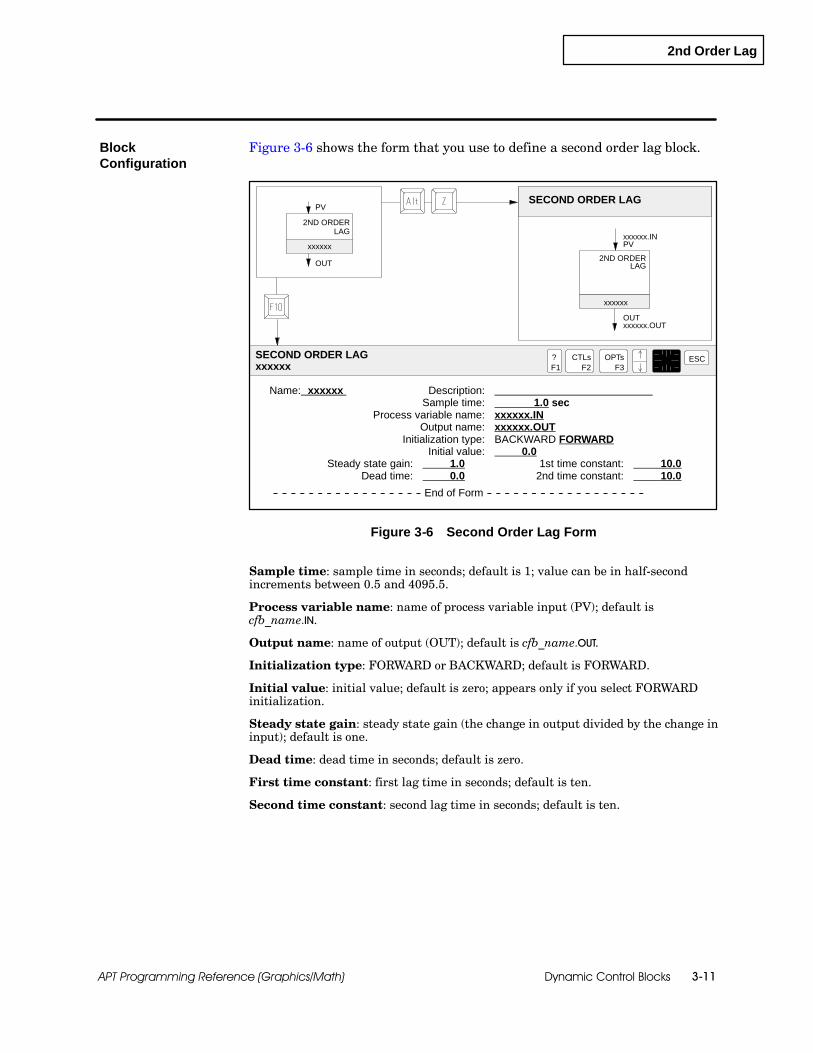
2nd Order Lag
Dynamic Control Blocks 3-11APT Programming Reference (Graphics/Math)
Figure 3-6 shows the form that you use to define a second order lag block.
Name: xxxxxx Description:Sample time: 1.0 sec
Process variable name: xxxxxx.INOutput name: xxxxxx.OUT
Initialization type: BACKWARD FORWARDInitial value: 0.0
Steady state gain: 1.0 1st time constant: 10.0Dead time: 0.0 2nd time constant: 10.0
-- -- -- -- -- -- -- -- -- -- -- -- -- -- -- -- -- End of Form -- -- -- -- -- -- -- -- -- -- -- -- -- -- -- -- -- --
OUT
SECOND ORDER LAG
xxxxxx.OUT
xxxxxx.INPV
SECOND ORDER LAGxxxxxx
?F1
ESCCTLsF2
OPTsF3
OUT
PV
xxxxxx
xxxxxx2ND ORDER
2ND ORDERLAG
LAG
Figure 3-6 Second Order Lag Form
Sample time: sample time in seconds; default is 1; value can be in half-secondincrements between 0.5 and 4095.5.
Process variable name: name of process variable input (PV); default iscfb_name.IN.
Output name: name of output (OUT); default is cfb_name.OUT.
Initialization type: FORWARD or BACKWARD; default is FORWARD.
Initial value: initial value; default is zero; appears only if you select FORWARDinitialization.
Steady state gain: steady state gain (the change in output divided by the change ininput); default is one.
Dead time: dead time in seconds; default is zero.
First time constant: first lag time in seconds; default is ten.
Second time constant: second lag time in seconds; default is ten.
BlockConfiguration
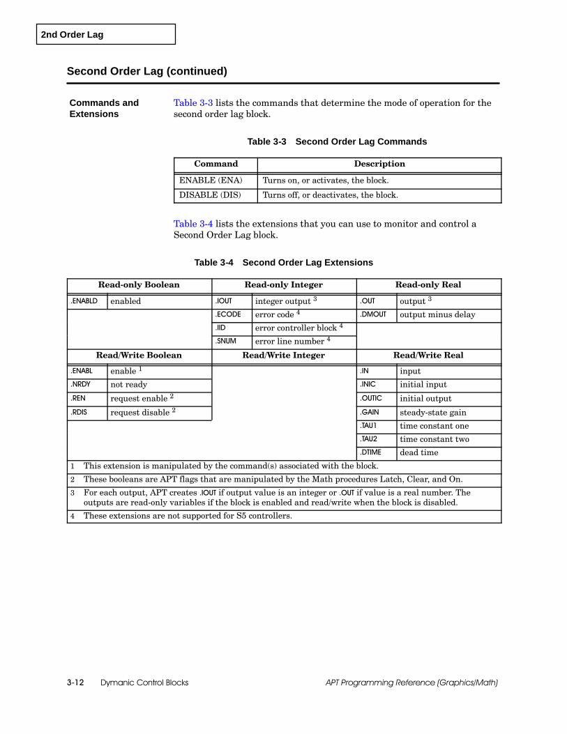
2nd Order Lag
Dymanic Control Blocks3-12 APT Programming Reference (Graphics/Math)
Second Order Lag (continued)
Table 3-3 lists the commands that determine the mode of operation for thesecond order lag block.
Table 3-3 Second Order Lag Commands
Command Description
ENABLE (ENA) Turns on, or activates, the block.
DISABLE (DIS) Turns off, or deactivates, the block.
Table 3-4 lists the extensions that you can use to monitor and control aSecond Order Lag block.
Table 3-4 Second Order Lag Extensions
Read-only Boolean Read-only Integer Read-only Real
.ENABLD enabled .IOUT integer output 3 .OUT output 3
.ECODE error code 4 .DMOUT output minus delay
.IID error controller block 4
.SNUM error line number 4
Read/Write Boolean Read/Write Integer Read/Write Real
.ENABL enable 1 .IN input
.NRDY not ready .INIC initial input
.REN request enable 2 .OUTIC initial output
.RDIS request disable 2 .GAIN steady-state gain
.TAU1 time constant one
.TAU2 time constant two
.DTIME dead time
1 This extension is manipulated by the command(s) associated with the block.
2 These booleans are APT flags that are manipulated by the Math procedures Latch, Clear, and On.
3 For each output, APT creates .IOUT if output value is an integer or .OUT if value is a real number. Theoutputs are read-only variables if the block is enabled and read/write when the block is disabled.
4 These extensions are not supported for S5 controllers.
Commands andExtensions

1st Order Lead Lag
Dynamic Control Blocks 3-13APT Programming Reference (Graphics/Math)
3.4 First Order Lead Lag
The first order lead lag block simulates a dynamic process in which specifiedtime constants determine both lead and lag times.
The output depends on the ratio of lead to lag as explained below. Assumethe following values in each example:
∆ input = 1.0 gain = 1.0
If TLead / TLag is greater than 1.0, then the initial responseovershoots the steady-state output value.
Initial output= ∆input * Gain ÆTLeadTLagÉ = 1.0 * 1.0 Æ2.0
1.0É = 2.0
2.0
n = 1 2 3
Yn
0
steady---state output = 1.0
4
If TLead / TLag is less than 1.0, then the initial response undershootsthe steady-state output value.
Initial output= ∆input * Gain ÆTLeadTLagÉ = 1.0 * 1.0 Æ1.02.0É = 0.5
0.5
n = 1 2 3
Yn
0
steady---state output = 1.0
4
If TLead / TLag is equal to 1.0, then the initial responseinstantaneously reaches the steady-state output value.
Initial output= ∆input * Gain ÆTLeadTLagÉ = 1.0 * 1.0 Æ1.0
1.0É = 1.0
n = 1 2 3
Yn
0
steady---state output = 1.0
4
Overview

1st Order Lead Lag
Dymanic Control Blocks3-14 APT Programming Reference (Graphics/Math)
First Order Lead Lag (continued)
Figure 3-7 shows the formula that is used for a first order lead lag block.
input outputgain(τ3 s+ 1)e−θs
τ1 s+ 1
Figure 3-7 First Order Lead Lag
Gain specifies the ratio of the change in output to the change in inputat a steady state.
τ1 specifies a time in seconds that is associated with the response tochange in the input that causes 63.2% of the change in output. It iscalled the lag time constant.
τ3 specifies a time in seconds that is associated with the lead responseafter a change in the input. It is called the lead time constant.
θ is the dead time in seconds.
s is the LaPlace operator.
First order lead lag blocks are available for Series 505 and S5 controllers.They are not supported for the 560/560T controllers.
Availability

1st Order Lead Lag
Dynamic Control Blocks 3-15APT Programming Reference (Graphics/Math)
Figure 3-8 shows the form that you use to define a first order lead lag block.
Name: xxxxxx Description:Sample time: 1.0 sec
Process variable name: xxxxxx.INOutput name: xxxxxx.OUT
Initialization type: BACKWARD FORWARDInitial value: 0.0
Steady state gain: 1.0 Lead time constant: 10.0Dead time: 0.0 Lag time constant: 10.0
-- -- -- -- -- -- -- -- -- -- -- -- -- -- -- -- -- End of Form -- -- -- -- -- -- -- -- -- -- -- -- -- -- -- -- -- --
OUT
FIRST ORDER LEAD LAG
xxxxxx.OUT
xxxxxx.INPV
FIRST ORDER LEAD LAGxxxxxx
?F1
ESCCTLsF2
OPTsF3
OUT
PV
xxxxxx
xxxxxx 1ST ORDER
1ST ORDERLEAD LAG
LEAD LAG
Figure 3-8 First Order Lead Lag Form
Sample time: sample time in seconds; default is 1; value can be in half--secondincrements between 0.5 and 4095.5.
Process variable name: name of process variable input (PV); default iscfb_name.IN.
Output name: name of output (OUT); default is cfb_name.OUT.
Initialization type: FORWARD or BACKWARD; default is FORWARD.
Initial value: initial value; default is zero; appears only if you select FORWARDinitialization.
Steady state gain: steady state gain (the change in output divided by the change ininput); default is one.
Dead time: dead time in seconds; default is zero.
Lead time constant: lead time in seconds; default is ten.
Lag time constant: lag time in seconds; default is ten.
BlockConfiguration

1st Order Lead Lag
Dymanic Control Blocks3-16 APT Programming Reference (Graphics/Math)
First Order Lead Lag (continued)
Table 3-5 lists the commands that determine the mode of operation for thefirst order lead lag block.
Table 3-5 First Order Lead Lag Commands
Command Description
ENABLE (ENA) Turns on, or activates, the block.
DISABLE (DIS) Turns off, or deactivates, the block.
Table 3-6 lists the extensions that you can use to monitor and control a firstorder lead lag block.
Table 3-6 First Order Lead Lag Extensions
Read-only Boolean Read-only Integer Read-only Real
.ENABLD enabled .IOUT integer output 3 .OUT output 3
.ECODE error code 4 .DMOUT output minus delay
.IID error controller block 4
.SNUM error line number 4
Read/Write Boolean Read/Write Integer Read/Write Real
.ENABL enable 1 .IN input
.NRDY not ready .INIC initial input
.REN request enable 2 .OUTIC initial output
.RDIS request disable 2 .GAIN steady-state gain
.TAU1 time constant one
.TLEAD lead time
.DTIME dead time
1 This extension is manipulated by the command(s) associated with the block.
2 These booleans are APT flags that are manipulated by the Math procedures Latch, Clear, and On.
3 For each output, APT creates .IOUT if output value is an integer or .OUT if value is a real number. Theoutputs are read-only variables if the block is enabled and read/write when the block is disabled.
4 These extensions are not supported for S5 controllers.
Commands andExtensions

1st Order Lag
Dynamic Control Blocks 3-17APT Programming Reference (Graphics/Math)
3.5 First Order Lag
The first order lag block simulates a dynamic process in which a specifiedfirst order time constant determines the relationship between an immediatechange in the input and a gradual corresponding change in the output.
Figure 3-9 shows the formula that is used for a first order lag block.
deadtime
input outputgain * e−θs
τ s+ 1
input
output
gain =∆ output∆ input
∆ input
∆ output
τ
63.2%
Figure 3-9 First Order Lag
Gain specifies the ratio of the change in output to the change in inputat a steady state.
τ specifies the time in seconds required to reach 63.2 per cent of thefinal output after a change in the input. It is the time constant.
θ is the dead time in seconds.
s is the LaPlace operator.
First order lag blocks are available for Series 505 and S5 controllers. Theyare not supported for the 560/560T controllers.
Overview
Availability

1st Order Lag
Dymanic Control Blocks3-18 APT Programming Reference (Graphics/Math)
First Order Lag (continued)
Figure 3-10 shows the form that you use to define a first order lag block.
Name: xxxxxx Description:Sample time: 1.0 sec
Process variable name: xxxxxx.INOutput name: xxxxxx.OUT
Initialization type: BACKWARD FORWARDInitial value: 0.0
Steady state gain: 1.0Dead time: 0.0
Time constant: 10.0
-- -- -- -- -- -- -- -- -- -- -- -- -- -- -- -- -- End of Form -- -- -- -- -- -- -- -- -- -- -- -- -- -- -- -- -- --
OUT
FIRST ORDER LAG
xxxxxx.OUT
xxxxxx.INPV
FIRST ORDER LAGxxxxxx
?F1
ESCCTLsF2
OPTsF3
OUT
PV
xxxxxx
xxxxxx1ST ORDER
1ST ORDERLAG
LAG
Figure 3-10 First Order Lag Form
Sample time: sample time in seconds; default is 1; value can be in half-secondincrements between 0.5 and 4095.5.
Process variable name: name of process variable input (PV); default iscfb_name.IN.
Output name: name of output (OUT); default is cfb_name.OUT.
Initialization type: FORWARD or BACKWARD; default is FORWARD.
Initial value: initial value; default is zero; appears only if you select FORWARDinitialization.
Steady state gain: steady state gain (the change in output divided by the change ininput); default is one.
Dead time: dead time in seconds; default is zero.
Time constant: time in seconds for output to reach 63.2% of final steady statevalue when responding to a step change in input; default is ten.
BlockConfiguration
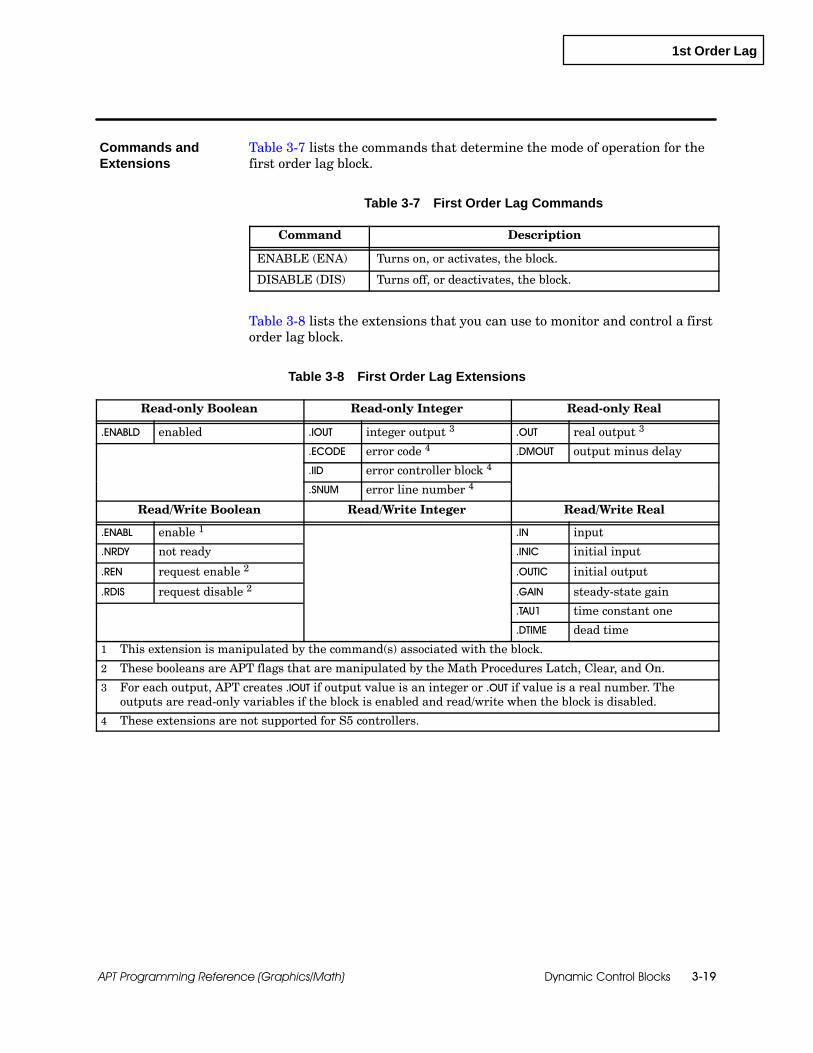
1st Order Lag
Dynamic Control Blocks 3-19APT Programming Reference (Graphics/Math)
Table 3-7 lists the commands that determine the mode of operation for thefirst order lag block.
Table 3-7 First Order Lag Commands
Command Description
ENABLE (ENA) Turns on, or activates, the block.
DISABLE (DIS) Turns off, or deactivates, the block.
Table 3-8 lists the extensions that you can use to monitor and control a firstorder lag block.
Table 3-8 First Order Lag Extensions
Read-only Boolean Read-only Integer Read-only Real
.ENABLD enabled .IOUT integer output 3 .OUT real output 3
.ECODE error code 4 .DMOUT output minus delay
.IID error controller block 4
.SNUM error line number 4
Read/Write Boolean Read/Write Integer Read/Write Real
.ENABL enable 1 .IN input
.NRDY not ready .INIC initial input
.REN request enable 2 .OUTIC initial output
.RDIS request disable 2 .GAIN steady-state gain
.TAU1 time constant one
.DTIME dead time
1 This extension is manipulated by the command(s) associated with the block.
2 These booleans are APT flags that are manipulated by the Math Procedures Latch, Clear, and On.
3 For each output, APT creates .IOUT if output value is an integer or .OUT if value is a real number. Theoutputs are read-only variables if the block is enabled and read/write when the block is disabled.
4 These extensions are not supported for S5 controllers.
Commands andExtensions

Derivative
Dymanic Control Blocks3-20 APT Programming Reference (Graphics/Math)
3.6 Derivative
The derivative block computes the rate of change in the input by using thefollowing formula:
Rate of change=∆ inputsample time
Figure 3-11 shows the formula that you use to define a derivative block.The result of this calculation is placed in the output field of the derivativeblock.
input outputinput (tj) − input (tj−1)
st
output
input
Figure 3-11 Derivative
You can use the derivative block to calculate the rate of change of a variable.You can set a flag if the rate of change exceeds a predetermined limit.
To monitor the rate of change of a variable, follow these steps:
1. Enable the block and wait for it to initialize:
cfb_name.ENABLD = true;
2. Monitor the rate of change of a certain variable as the output of thederivative block.
3. If the rate of change becomes too great, set a flag that identifies thecondition.
Derivative blocks are available for Series 505 and S5 controllers. They arenot supported for the 560/560T controllers.
Overview
Availability

Derivative
Dynamic Control Blocks 3-21APT Programming Reference (Graphics/Math)
Figure 3-12 shows the form that you use to define a derivative block.
Name: xxxxxx Description:Sample time: 1.0 sec
Process variable name: xxxxxx.INOutput name: xxxxxx.OUT
-- -- -- -- -- -- -- -- -- -- -- -- -- -- -- -- -- End of Form -- -- -- -- -- -- -- -- -- -- -- -- -- -- -- -- -- --
OUT
DERIVATIVE
xxxxxx.OUT
xxxxxx.INPV
DERIVATIVExxxxxx
?F1
ESCCTLsF2
OPTsF3
OUT
PV
xxxxxx
xxxxxx
DERIVATIVE
DERIV--ATIVE
Figure 3-12 Derivative Form
Sample time: sample time in seconds; default is 1; value can be in half-secondincrements between 0.5 and 4095.5.
Process variable name: name of process variable input (PV); default iscfb_name.IN.
Output name: name of output (OUT); default is cfb_name.OUT.
BlockConfiguration

Derivative
Dymanic Control Blocks3-22 APT Programming Reference (Graphics/Math)
Derivative (continued)
Table 3-9 lists the commands that determine the mode of operation for thederivative block.
Table 3-9 Derivative Commands
Command Description
ENABLE (ENA) Turns on, or activates, the block.
DISABLE (DIS) Turns off, or deactivates, the block.
Table 3-10 lists the extensions that you can use to monitor and control aderivative block.
Table 3-10 Derivative Extensions
Read-only Boolean Read-only Integer Read-only Real
.ENABLD enabled .IOUT integer output 3 .OUT real output 3
.ECODE error code 4
.IID error controller block 4
.SNUM error line number 4
Read/Write Boolean Read/Write Integer Read/Write Real
.ENABL enable 1 .IN input
.NRDY not ready
.REN request enable 2
.RDIS request disable 2
1 This extension is manipulated by the command(s) associated with the block.
2 These booleans are APT flags that are manipulated by the Math procedures Latch, Clear, and On.
3 For each output, APT creates .IOUT if output value is an integer or .OUT if value is a real number. Theoutputs are read-only variables if the block is enabled and read/write when the block is disabled.
4 These extensions are not supported for S5 controllers.
Commands andExtensions
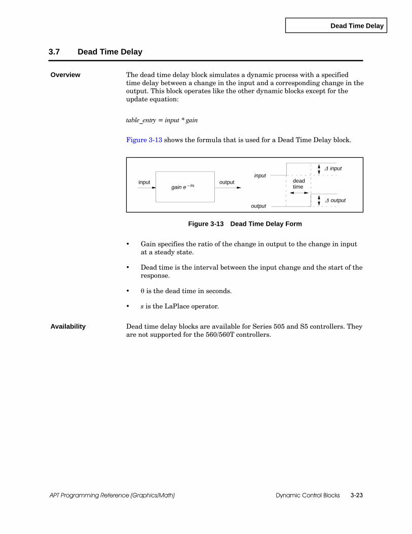
Dead Time Delay
Dynamic Control Blocks 3-23APT Programming Reference (Graphics/Math)
3.7 Dead Time Delay
The dead time delay block simulates a dynamic process with a specifiedtime delay between a change in the input and a corresponding change in theoutput. This block operates like the other dynamic blocks except for theupdate equation:
table_entry = input * gain
Figure 3-13 shows the formula that is used for a Dead Time Delay block.
input
output
deadtime
input outputgain e−θs
∆ input
∆ output
Figure 3-13 Dead Time Delay Form
Gain specifies the ratio of the change in output to the change in inputat a steady state.
Dead time is the interval between the input change and the start of theresponse.
θ is the dead time in seconds.
s is the LaPlace operator.
Dead time delay blocks are available for Series 505 and S5 controllers. Theyare not supported for the 560/560T controllers.
Overview
Availability
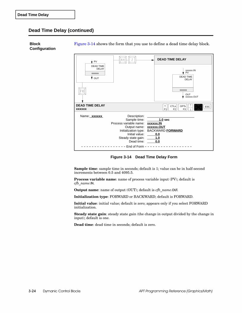
Dead Time Delay
Dymanic Control Blocks3-24 APT Programming Reference (Graphics/Math)
Dead Time Delay (continued)
Figure 3-14 shows the form that you use to define a dead time delay block.
Name: xxxxxx Description:Sample time: 1.0 sec
Process variable name: xxxxxx.INOutput name: xxxxxx.OUT
Initialization type: BACKWARD FORWARDInitial value: 0.0
Steady state gain: 1.0Dead time: 0.0
-- -- -- -- -- -- -- -- -- -- -- -- -- -- -- -- -- End of Form -- -- -- -- -- -- -- -- -- -- -- -- -- -- -- -- -- --
OUT
DEAD TIME DELAY
xxxxxx.OUT
xxxxxx.INPV
DEAD TIME DELAYxxxxxx
?F1
ESCCTLsF2
OPTsF3
OUT
PV
xxxxxx
xxxxxxDEAD TIME
DELAY
DEAD TIMEDELAY
Figure 3-14 Dead Time Delay Form
Sample time: sample time in seconds; default is 1; value can be in half-secondincrements between 0.5 and 4095.5.
Process variable name: name of process variable input (PV); default iscfb_name.IN.
Output name: name of output (OUT); default is cfb_name.OUT.
Initialization type: FORWARD or BACKWARD; default is FORWARD.
Initial value: initial value; default is zero; appears only if you select FORWARDinitialization.
Steady state gain: steady state gain (the change in output divided by the change ininput); default is one.
Dead time: dead time in seconds; default is zero.
BlockConfiguration
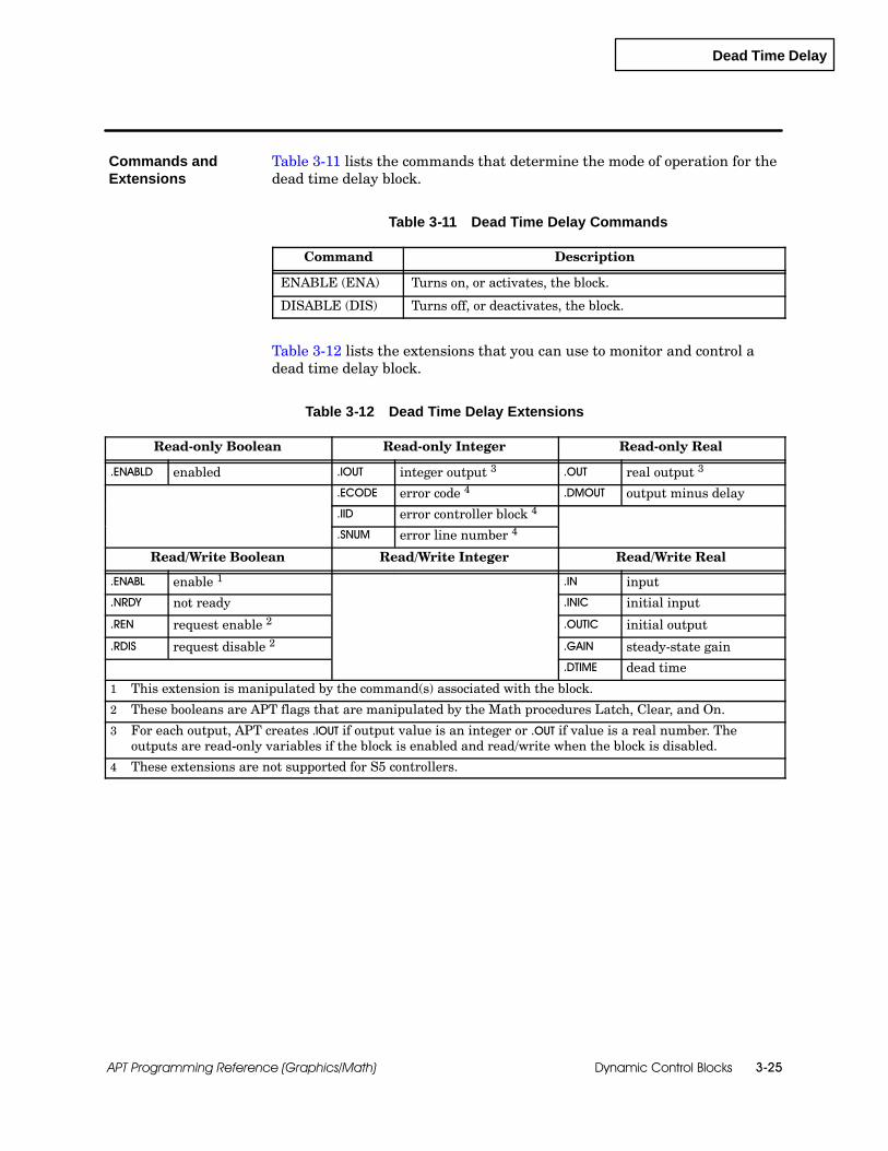
Dead Time Delay
Dynamic Control Blocks 3-25APT Programming Reference (Graphics/Math)
Table 3-11 lists the commands that determine the mode of operation for thedead time delay block.
Table 3-11 Dead Time Delay Commands
Command Description
ENABLE (ENA) Turns on, or activates, the block.
DISABLE (DIS) Turns off, or deactivates, the block.
Table 3-12 lists the extensions that you can use to monitor and control adead time delay block.
Table 3-12 Dead Time Delay Extensions
Read-only Boolean Read-only Integer Read-only Real
.ENABLD enabled .IOUT integer output 3 .OUT real output 3
.ECODE error code 4 .DMOUT output minus delay
.IID error controller block 4
.SNUM error line number 4
Read/Write Boolean Read/Write Integer Read/Write Real
.ENABL enable 1 .IN input
.NRDY not ready .INIC initial input
.REN request enable 2 .OUTIC initial output
.RDIS request disable 2 .GAIN steady-state gain
.DTIME dead time
1 This extension is manipulated by the command(s) associated with the block.
2 These booleans are APT flags that are manipulated by the Math procedures Latch, Clear, and On.
3 For each output, APT creates .IOUT if output value is an integer or .OUT if value is a real number. Theoutputs are read-only variables if the block is enabled and read/write when the block is disabled.
4 These extensions are not supported for S5 controllers.
Commands andExtensions
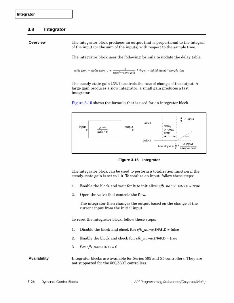
Integrator
Dymanic Control Blocks3-26 APT Programming Reference (Graphics/Math)
3.8 Integrator
The integrator block produces an output that is proportional to the integralof the input (or the sum of the inputs) with respect to the sample time.
The integrator block uses the following formula to update the delay table:
table entry = (table entry1 ) +1.0
steady---state gain* (input --- initial input) * sample time
The steady-state gain (.TAU1) controls the rate of change of the output. Alarge gain produces a slow integrator; a small gain produces a fastintegrator.
Figure 3-15 shows the formula that is used for an integrator block.
input
output
delayor deadtime
input outpute−θsgain * s
∆ input
line slope = 1τ *
∆ inputsample time
Figure 3-15 Integrator
The integrator block can be used to perform a totalization function if thesteady-state gain is set to 1.0. To totalize an input, follow these steps:
1. Enable the block and wait for it to initialize: cfb_name.ENABLD = true
2. Open the valve that controls the flow.
The integrator then changes the output based on the change of thecurrent input from the initial input.
To reset the integrator block, follow these steps:
1. Disable the block and check for: cfb_name.ENABLD = false
2. Enable the block and check for: cfb_name.ENABLD = true
3. Set cfb_name.INIC = 0
Integrator blocks are available for Series 505 and S5 controllers. They arenot supported for the 560/560T controllers.
Overview
Availability

Integrator
Dynamic Control Blocks 3-27APT Programming Reference (Graphics/Math)
Figure 3-16 shows the form that you use to define an integrator block.
Name: xxxxxx Description:Sample time: 1.0 sec
Process variable name: xxxxxx.INOutput name: xxxxxx.OUT
Initialization type: BACKWARD FORWARDInitial value: 0.0
Steady state gain: 1.0Dead time: 0.0
-- -- -- -- -- -- -- -- -- -- -- -- -- -- -- -- -- End of Form -- -- -- -- -- -- -- -- -- -- -- -- -- -- -- -- -- --
OUT
INTEGRATOR
xxxxxx.OUT
xxxxxx.INPV
INTEGRATORxxxxxx
?F1
ESCCTLsF2
OPTsF3
OUT
PV
xxxxxx
xxxxxx
INTEGRATOR
INTE--GRATOR
Figure 3-16 Integrator Form
Sample time: sample time in seconds; default is 1; value can be in half-secondincrements between 0.5 and 4095.5.
Process variable name: name of process variable input (PV); default iscfb_name.IN.
Output name: name of output (OUT); default is cfb_name.OUT.
Initialization type: FORWARD or BACKWARD; default is FORWARD.
Initial value: initial value; default is zero; appears only if you select FORWARDinitialization.
Steady state gain: 1 / (steady state gain) is the slope of the integrator output witha constant input.
Dead time: dead time in seconds; default is zero.
BlockConfiguration

Integrator
Dymanic Control Blocks3-28 APT Programming Reference (Graphics/Math)
Integrator (continued)
Table 3-13 lists the commands that determine the mode of operation for theintegrator block.
Table 3-13 Integrator Commands
Command Description
ENABLE (ENA) Turns on, or activates, the block.
DISABLE (DIS) Turns off, or deactivates, the block.
Table 3-14 lists the extensions that you can use to monitor and control anintegrator block.
Table 3-14 Integrator Extensions
Read-only Boolean Read-only Integer Read-only Real
.ENABLD enabled .IOUT integer output 3 .OUT real output 3
.ECODE error code 4 .DMOUT output minus delay
.IID error controller block 4
.SNUM error line number 4
Read/Write Boolean Read/Write Integer Read/Write Real
.ENABL enable 1 .IN input
.NRDY not ready .INIC initial input
.REN request enable 2 .OUTIC initial output
.RDIS request disable 2 .GAIN steady-state gain
.TAU1 time constant one
.DTIME dead time
1 This extension is manipulated by the command(s) associated with the block.
2 These booleans are APT flags that are manipulated by the Math procedures Latch, Clear, and On.
3 For each output, APT creates .IOUT if output value is an integer or .OUT if value is a real number. Theoutputs are read-only variables if the block is enabled and read/write when the block is disabled.
4 These extensions are not supported for S5 controllers.
Commands andExtensions
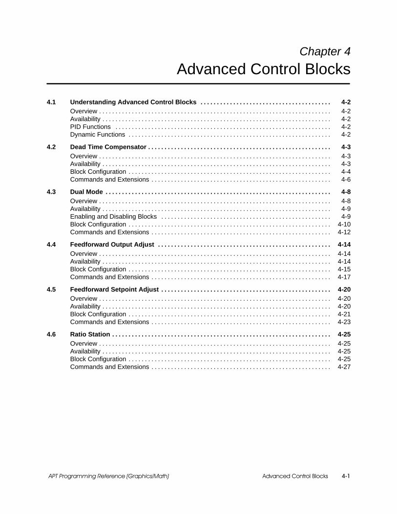
Advanced Control Blocks 4-1APT Programming Reference (Graphics/Math)
Chapter 4
Advanced Control Blocks
4.1 Understanding Advanced Control Blocks 4-2. . . . . . . . . . . . . . . . . . . . . . . . . . . . . . . . . . . . . . . .Overview 4-2. . . . . . . . . . . . . . . . . . . . . . . . . . . . . . . . . . . . . . . . . . . . . . . . . . . . . . . . . . . . . . . . . . . . . . .Availability 4-2. . . . . . . . . . . . . . . . . . . . . . . . . . . . . . . . . . . . . . . . . . . . . . . . . . . . . . . . . . . . . . . . . . . . . .PID Functions 4-2. . . . . . . . . . . . . . . . . . . . . . . . . . . . . . . . . . . . . . . . . . . . . . . . . . . . . . . . . . . . . . . . . .Dynamic Functions 4-2. . . . . . . . . . . . . . . . . . . . . . . . . . . . . . . . . . . . . . . . . . . . . . . . . . . . . . . . . . . . . .
4.2 Dead Time Compensator 4-3. . . . . . . . . . . . . . . . . . . . . . . . . . . . . . . . . . . . . . . . . . . . . . . . . . . . . . . .Overview 4-3. . . . . . . . . . . . . . . . . . . . . . . . . . . . . . . . . . . . . . . . . . . . . . . . . . . . . . . . . . . . . . . . . . . . . . .Availability 4-3. . . . . . . . . . . . . . . . . . . . . . . . . . . . . . . . . . . . . . . . . . . . . . . . . . . . . . . . . . . . . . . . . . . . . .Block Configuration 4-4. . . . . . . . . . . . . . . . . . . . . . . . . . . . . . . . . . . . . . . . . . . . . . . . . . . . . . . . . . . . . .Commands and Extensions 4-6. . . . . . . . . . . . . . . . . . . . . . . . . . . . . . . . . . . . . . . . . . . . . . . . . . . . . . .
4.3 Dual Mode 4-8. . . . . . . . . . . . . . . . . . . . . . . . . . . . . . . . . . . . . . . . . . . . . . . . . . . . . . . . . . . . . . . . . . . . .Overview 4-8. . . . . . . . . . . . . . . . . . . . . . . . . . . . . . . . . . . . . . . . . . . . . . . . . . . . . . . . . . . . . . . . . . . . . . .Availability 4-9. . . . . . . . . . . . . . . . . . . . . . . . . . . . . . . . . . . . . . . . . . . . . . . . . . . . . . . . . . . . . . . . . . . . . .Enabling and Disabling Blocks 4-9. . . . . . . . . . . . . . . . . . . . . . . . . . . . . . . . . . . . . . . . . . . . . . . . . . . .Block Configuration 4-10. . . . . . . . . . . . . . . . . . . . . . . . . . . . . . . . . . . . . . . . . . . . . . . . . . . . . . . . . . . . . .Commands and Extensions 4-12. . . . . . . . . . . . . . . . . . . . . . . . . . . . . . . . . . . . . . . . . . . . . . . . . . . . . . .
4.4 Feedforward Output Adjust 4-14. . . . . . . . . . . . . . . . . . . . . . . . . . . . . . . . . . . . . . . . . . . . . . . . . . . . .Overview 4-14. . . . . . . . . . . . . . . . . . . . . . . . . . . . . . . . . . . . . . . . . . . . . . . . . . . . . . . . . . . . . . . . . . . . . . .Availability 4-14. . . . . . . . . . . . . . . . . . . . . . . . . . . . . . . . . . . . . . . . . . . . . . . . . . . . . . . . . . . . . . . . . . . . . .Block Configuration 4-15. . . . . . . . . . . . . . . . . . . . . . . . . . . . . . . . . . . . . . . . . . . . . . . . . . . . . . . . . . . . . .Commands and Extensions 4-17. . . . . . . . . . . . . . . . . . . . . . . . . . . . . . . . . . . . . . . . . . . . . . . . . . . . . . .
4.5 Feedforward Setpoint Adjust 4-20. . . . . . . . . . . . . . . . . . . . . . . . . . . . . . . . . . . . . . . . . . . . . . . . . . . .Overview 4-20. . . . . . . . . . . . . . . . . . . . . . . . . . . . . . . . . . . . . . . . . . . . . . . . . . . . . . . . . . . . . . . . . . . . . . .Availability 4-20. . . . . . . . . . . . . . . . . . . . . . . . . . . . . . . . . . . . . . . . . . . . . . . . . . . . . . . . . . . . . . . . . . . . . .Block Configuration 4-21. . . . . . . . . . . . . . . . . . . . . . . . . . . . . . . . . . . . . . . . . . . . . . . . . . . . . . . . . . . . . .Commands and Extensions 4-23. . . . . . . . . . . . . . . . . . . . . . . . . . . . . . . . . . . . . . . . . . . . . . . . . . . . . . .
4.6 Ratio Station 4-25. . . . . . . . . . . . . . . . . . . . . . . . . . . . . . . . . . . . . . . . . . . . . . . . . . . . . . . . . . . . . . . . . . .Overview 4-25. . . . . . . . . . . . . . . . . . . . . . . . . . . . . . . . . . . . . . . . . . . . . . . . . . . . . . . . . . . . . . . . . . . . . . .Availability 4-25. . . . . . . . . . . . . . . . . . . . . . . . . . . . . . . . . . . . . . . . . . . . . . . . . . . . . . . . . . . . . . . . . . . . . .Block Configuration 4-25. . . . . . . . . . . . . . . . . . . . . . . . . . . . . . . . . . . . . . . . . . . . . . . . . . . . . . . . . . . . . .Commands and Extensions 4-27. . . . . . . . . . . . . . . . . . . . . . . . . . . . . . . . . . . . . . . . . . . . . . . . . . . . . . .

Advanced Control Blocks4-2 APT Programming Reference (Graphics/Math)
4.1 Understanding Advanced Control Blocks
The advanced control blocks provide a combination of PID and dynamiccontrol.
The dead time compensator removes the effect of dead time from thesetpoint response of a single input/output process.
The dual mode block combines PID control with on/off control.
Two blocks provide feedforward control: feedforward output adjust, andfeedforward setpoint adjust.
The ratio station block keeps a constant ratio between two variables.
Advanced control blocks are available for Series 505 and S5 controllers.They are not supported for the 560/560T controllers.
The advanced control blocks have the basic functionality of the PID loops.See the appropriate section of Chapter 2, “Standard Control Blocks,” for anexplanation of the operation of the PID block. The external anti-resetwindup protection can also be used with dynamic blocks. See Chapter 9,“Other Control Blocks,” for information about these control blocks.
Some of the advanced control blocks incorporate the lead and lead-lagfunctions of the dynamic blocks. Refer to Chapter 3 for details on dynamiccontrol blocks to determine the parameters for first order lag, first orderlead-lag, second order lag, and second order lead-lag.
Overview
Availability
PID Functions
Dynamic Functions
Dead Time Compensator
Advanced Control Blocks 4-3APT Programming Reference (Graphics/Math)
4.2 Dead Time Compensator
The dead time compensator block removes the effect of dead time from thesetpoint response of a single input, single output process.
The dead time compensator includes a PID loop and has the same basicoptions and operating characteristics as those listed in Chapter 2 onstandard control blocks. However, you cannot include any associated mathand you must configure the dynamic model.
The dead time compensator block is basically the traditional SmithPredictor control algorithm. You have the option of choosing either a first orsecond order lag plus a dead time dynamic model.
The model is driven by the output of the PID that also controls the inputvariable. The output is sent through a model with a dead time block and issubtracted from the process input to generate an error. The error and themodel output are added together and sent to the PID loop as the processsignal.
Two extension variables are used to compute the process signal: .MOUT(model output including the delay) and .DMOUT (model output without thedelay). The signal is based on the following formula.
cfb_name.LPV = cvb_name.DMOUT + (cfb_name.LPV --- cfb_name.MOUT)
This value can also be monitored with the .SPV (“seen” process variable)extension.
Dead time compensator blocks are available for Series 505 and S5controllers. They are not supported for the 560/560T controllers.
Overview
Availability

Dead Time Compensator
Advanced Control Blocks4-4 APT Programming Reference (Graphics/Math)
Dead Time Compensator (continued)
Figure 4-1 shows the dead time compensator CFB graphic.
DEAD TIME COMPENSATOR
P I D
OUT
SP
OUT
PVSPSP
xxxxxx
P I D DEADTIME
xxxxxx.OUT
PV
xxxxxx.PV
MODEL
Block Name: xxxxxx
DELAY
+
+
+
XXXXXX.SPV
xxxxxx.MOUT
XXXXXX.DMOUT
xxxxxx.OUT
--
Figure 4-1 Dead Time Compensator CFB
Figure 4-2 shows the form that you use to define the dead time compensatorblock. The shaded entries in the form depend on the previous selection. Theinformation on the form is the same as the PID block except that you cannothave associated math. See page 2-9 for process variable information,page 2-11 for process setpoint information, page 2-13 for output information,page 2-15 for controller options, and pages 2-21 to 2-23 for PID commandsand extensions and for a description of the PID options that apply to thedead time compensator block. Also see Section 3.2, “Second Order LeadLag,” Section 3.3, “Second Order Lag,” Section 3.4, “First Order Lead Lag,”and Section 3.5, “First Order Lag,” for a description of the dynamic optionsthat apply to the dead time compensator block.
BlockConfiguration

Dead Time Compensator
Advanced Control Blocks 4-5APT Programming Reference (Graphics/Math)
DEAD TIME COMPENSATORxxxxxx
?F1
ESCCTLsF2
OPTsF3
Name: xxxxxx Description:Sample time: 1.0 sec
Algorithm type: POSITIONPLC address: Automatic User Assigned
{If user assigned} Reserved address:
Process Variable Information -- -- -- -- -- -- -- -- -- -- -- -- -- -- -- -- -- -- -- -- -- -- -- -- -- -- --Process variable: xxxxxx.PV S
Low range: 0.0 Alarm dead band: 0.01High range: 1.0 Low low alarm: 0.1Eng. units: __________ Low alarm: 0.2
{if ANALOG INPUT or if PV is scaled integer} High alarm: 0.8High high alarm: 0.9
Rate of change alarm: 1.0
Process Setpoint Information -- -- -- -- -- -- -- -- -- -- -- -- -- -- -- -- -- -- -- -- -- -- -- -- -- -- --Setpoint source: CASCADED COMPUTED NONE
{if CASCADED} Loop name: <------>{if COMPUTED} Setpoint name: xxxxxx.RSP <------>
Minimum setpoint: 0.0Maximum setpoint: 1.0
Yellow(low) deviation alarm: 0.1Orange(high) deviation alarm: 0.2
Output Information -- -- -- -- -- -- -- -- -- -- -- -- -- -- -- -- -- -- -- -- -- -- -- -- -- -- -- -- -- -- -- --Output name: xxxxxx.OUT S
Limit output between 0% and 100%? [ ]Minimum output(%): 0.0
Maximum output(%): 100.0
Controller Options -- -- -- -- -- -- -- -- -- -- -- -- -- -- -- -- -- -- -- -- -- -- -- -- -- -- -- -- -- -- -- --Error algorithm type? NORMAL SQUARED DEADBAND
Reverse acting? [ ]Freeze bias for output out of range? [ ]
Tuning Parameters -- -- -- -- -- -- -- -- -- -- -- -- -- -- -- -- -- -- -- -- -- -- -- -- -- -- -- -- -- -- -- --Loop type: PI P PID I PD
Proportional gain: 1.0Integral time (reset time): 999.99 min
Derivative time (rate): 0.0 minDerivative gain limiting? [ ]
Limiting coefficient: 10.0
Dynamic Function -- -- -- -- -- -- -- -- -- -- -- -- -- -- -- -- -- -- -- -- -- -- -- -- -- -- -- -- -- -- -- --Dynamic function type: 1st ORDER LAG 2nd ORDER LAG
Second Order Lag -- -- -- -- -- -- -- -- -- -- -- -- -- -- -- -- -- -- -- -- -- -- -- -- -- -- -- -- -- -- -- --Steady state gain: 1.0 1st time constant: 20.0
Dead time: 0.0 2nd time constant: 10.0
-- -- -- -- -- -- -- -- -- -- -- -- -- -- -- -- -- End of Form -- -- -- -- -- -- -- -- -- -- -- -- -- -- -- -- -- --
Series 505 only
Figure 4-2 Dead Time Compensator Form
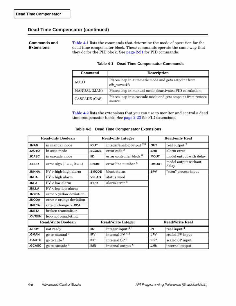
Dead Time Compensator
Advanced Control Blocks4-6 APT Programming Reference (Graphics/Math)
Dead Time Compensator (continued)
Table 4-1 lists the commands that determine the mode of operation for thedead time compensator block. These commands operate the same way thatthey do for the PID block. See page 2-21 for PID commands.
Table 4-1 Dead Time Compensator Commands
Command Description
AUTOPlaces loop in automatic mode and gets setpoint fromcfb_name.SP.
MANUAL (MAN) Places loop in manual mode; deactivates PID calculation.
CASCADE (CAS) Places loop into cascade mode and gets setpoint from remotesource.
Table 4-2 lists the extensions that you can use to monitor and control a deadtime compensator block. See page 2-23 for PID extensions.
Table 4-2 Dead Time Compensator Extensions
Read-only Boolean Read-only Integer Read-only Real
.IMAN in manual mode .IOUT integer/analog output 2,8 .OUT real output 2
.IAUTO in auto mode .ECODE error code 8 .ERR alarm error
.ICASC in cascade mode .IID error controller block 8 .MOUT model output with delay
.SERR error sign (1 = --, 0 = +) .SNUM error line number 8 .DMOUTmodel output withoutdelay
.INHHA PV > high-high alarm .SMODE block status .SPV “seen” process input
.INHA PV > high alarm .VFLAG status word
.INLA PV < low alarm .IERR alarm error 3
.INLLA PV < low-low alarm
.INYDA error > yellow deviation
.INODA error > orange deviation
.INRCA rate of change > .RCA
.INBTA broken transmitter
.OVRUN loop not completing
Read/Write Boolean Read/Write Integer Read/Write Real
.NRDY not ready .IIN integer input 4,8 .IN real input 4
.GMAN go to manual 1 .IPV internal PV 4,8 .LPV scaled PV input
.GAUTO go to auto 1 .ISP internal SP 8 .LSP scaled SP input
.GCASC go to cascade 1 .IMN internal output 8 .LMN internal output
Commands andExtensions

Dead Time Compensator
Advanced Control Blocks 4-7APT Programming Reference (Graphics/Math)
Table 4-2 Dead Time Compensator Extensions (continued)
Read/Write Boolean (continued) Read/Write Integer (continued) Read/Write Real (continued)
.RMAN go to manual 5 .AWS anti-reset windup 6 .HLIM high limit for output
.RATO go to auto 5 .CFL C-flag low .LLIM low limit for output
.RCAS go cascade 5 .CFH C-flag high .PV real input 4
.IBIAS integer value of bias 8 .RSP setpoint source 7
.ST sample time
.PVH PV high range
.PVL PV low range
.KC proportional gain
.TI integral time
.TD derivative time
.HHA high-high alarm limit
.HA high alarm limit
.LA low alarm limit
.LLA low-low alarm limit
.ODA orange deviation limit
.YDA yellow deviation limit
.RCA rate-of-change limit
.SP setpoint
.SPH setpoint high limit
.SPL setpoint low limit
.GAIN steady-state gain
.TAU1 time constant one
.TAU2 time constant two
.DTIME dead time
.BIAS integral of loop error
1 These extensions are manipulated by the command(s) associated with the block.
2 For each output, APT creates .IOUT if output value is an integer or .OUT if value is a real number. Theoutputs are read-only variables if block is in auto or cascade and read/write when block is manual.
3 The .IERR extension is generated only when a Series 505 Thermocouple or RTD input (8WX version) isconfigured.
4 For each input, APT creates .IIN if input value is an integer or .IN if value is a real number. The value ofthe .PV extension is identical to that of the .IN extension (.IIN is identical to .IPV).
5 These booleans are APT flags that are manipulated by the Math procedures Latch, Clear, and On.
6 If a PID block is associated with an Anti-Reset Windup block, the Anti-Reset Windup CFB controls thisvalue.
7 If setpoint source is computed, this .RSP or a real variable can be entered as setpoint source. If setpointsource is cascaded, .RSP is an alternate name for the source loop .OUT extension variable.
8 These extensions are not supported for S5 controllers.
Dual Mode
Advanced Control Blocks4-8 APT Programming Reference (Graphics/Math)
4.3 Dual Mode
The dual mode block provides a mechanism to start up a process variable ina minimum amount of time and with a minimum amount of overshoot.
The dual mode block combines PID control with on/off control. The PID loopmust be in auto or cascade mode before you enable the dual mode block. ThePID loop has the same options and operating characteristics as those listedin Chapter 2, “Standard Control Blocks.” You cannot include associatedmath on the output because the dual mode block operates on the output ofthe PID loop.
To properly control the dual mode block, include these steps in an SFC:
1. Place the PID loop in auto or cascade.
2. After the loop is in the appropriate mode, enable the dual mode block.
3. Change the setpoint to the desired value to move the process variableinto orange deviation.
When the dual mode block is enabled, the .DMODE extension is set to 1 andretains that value until the PID loop takes control. When the processdeviation crosses the orange deviation line, the following steps occur(Figure 4-3):
1. The output is set to 100% until the process re-crosses the orangedeviation line.
2. The output is set to 0% for the first time interval that you specify(Delay time 1).
3. The output is set to the preset value for the second time interval thatyou specify (Delay time 2).
4. The bias is set to the preset value, and control is returned to the PIDloop.
5. The dual mode portion is deactivated until it is reset with an ENABLEcommand.
The orange deviation and the delay times are the critical tuning constantsfor proper operation of the dual mode block. The block assumes that theprocess variable starts at a point below the orange deviation limit. Initialsetpoint change must be large enough to push the error into orangedeviation.
After the loop gets control of the process, you can change the deviationlimits by writing to the appropriate extension variables.
Overview

Dual Mode
Advanced Control Blocks 4-9APT Programming Reference (Graphics/Math)
Yellow deviation
Yellow deviation
Orange deviation
Orange deviation
Error
100%
0%
Preset
delaytime 1
delaytime 2
Loop control takes over
error crossesorange deviation
error re-crossesorange deviation
.DMODE = 0.DMODE = 1
Setpoint
Output
Figure 4-3 Dual Mode Operation
Dual mode blocks are available for Series 505 and S5 controllers. They arenot supported for the 560/560T controllers.
The dual mode CFB must be activated with the ENABLE command or withan assignment statement that sets the .ENABL extension to true. SeeFigure 4-4. The dual mode block can also be enabled from an assignmentstatement wherever you can use the Math language, for example, SFCsteps, CFBs, etc.
cfb_name.ENABL := true;Enable cfb_name;
S3 ENABLE cfb_name;
A
xxxxxx
MATH
B C D
E F G H
Figure 4-4 Enabling a Dual Mode CFB
Availability
Enabling andDisabling Blocks

Dual Mode
Advanced Control Blocks4-10 APT Programming Reference (Graphics/Math)
Dual Mode (continued)
To deactivate the dual mode CFB, use the DISABLE command with theblock name or set the .ENABL extension to false.
The dual mode block has a boolean extension (.NRDY) that you can use tointerlock the execution of the block to some external conditions:
If you set the .NRDY extension to true, the block is forced to the disabledstate.
To return the block to the enabled state you must not only set the.NRDY extension to false, but you must also re-enable the block with acommand or an assignment statement.
Figure 4-5 shows the dual mode CFB graphic.
OUT
PVSPSP
xxxxxx
P I D DUALMODE
OUT
SP
xxxxxx.DOUT
xxxxxx.PVPV
P
I
Dxxxxxx
DUAL MODE
DUAL MODE
Figure 4-5 Dual Mode Graphic
Figure 4-6 shows the form that you use to define the dual mode block. Theshaded entries in the form depend on the previous selection. Theinformation on the form is the same as the PID block except that you cannothave associated math on the output and you must enter the dual modeparameters. See page 2-9 for process variable information, page 2-11 forprocess setpoint information, page 2-13 for output information, page 2-15 forcontroller options, and pages 2-21 to 2-23 for PID commands and extensionsand for a description of the PID options that apply to the dual mode block.
BlockConfiguration
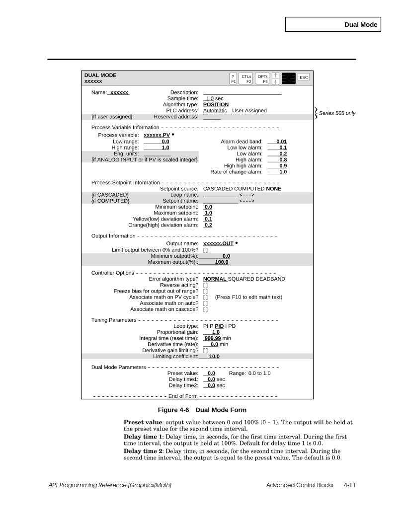
Dual Mode
Advanced Control Blocks 4-11APT Programming Reference (Graphics/Math)
DUAL MODExxxxxx
?F1
ESCCTLsF2
OPTsF3
Name: xxxxxx Description:Sample time: 1.0 sec
Algorithm type: POSITIONPLC address: Automatic User Assigned
{If user assigned} Reserved address: ______
Process Variable Information -- -- -- -- -- -- -- -- -- -- -- -- -- -- -- -- -- -- -- -- -- -- -- -- -- -- --Process variable: xxxxxx.PV S
Low range: 0.0 Alarm dead band: 0.01High range: 1.0 Low low alarm: 0.1Eng. units: __________ Low alarm: 0.2
{if ANALOG INPUT or if PV is scaled integer} High alarm: 0.8High high alarm: 0.9
Rate of change alarm: 1.0
Process Setpoint Information -- -- -- -- -- -- -- -- -- -- -- -- -- -- -- -- -- -- -- -- -- -- -- -- -- -- --Setpoint source: CASCADED COMPUTED NONE
{if CASCADED} Loop name: <------>{if COMPUTED} Setpoint name: <------>
Minimum setpoint: 0.0Maximum setpoint: 1.0
Yellow(low) deviation alarm: 0.1Orange(high) deviation alarm: 0.2
Output Information -- -- -- -- -- -- -- -- -- -- -- -- -- -- -- -- -- -- -- -- -- -- -- -- -- -- -- -- -- -- -- --Output name: xxxxxx.OUT S
Limit output between 0% and 100%? [ ]Minimum output(%): 0.0
Maximum output(%):: 100.0
Controller Options -- -- -- -- -- -- -- -- -- -- -- -- -- -- -- -- -- -- -- -- -- -- -- -- -- -- -- -- -- -- -- --Error algorithm type? NORMAL SQUARED DEADBAND
Reverse acting? [ ]Freeze bias for output out of range? [ ]
Associate math on PV cycle? [ ] (Press F10 to edit math text)Associate math on auto? [ ]
Associate math on cascade? [ ]
Tuning Parameters -- -- -- -- -- -- -- -- -- -- -- -- -- -- -- -- -- -- -- -- -- -- -- -- -- -- -- -- -- -- -- --Loop type: PI P PID I PD
Proportional gain: 1.0Integral time (reset time): 999.99 min
Derivative time (rate): 0.0 minDerivative gain limiting? [ ]
Limiting coefficient: 10.0
Dual Mode Parameters -- -- -- -- -- -- -- -- -- -- -- -- -- -- -- -- -- -- -- -- -- -- -- -- -- -- -- -- -- --Preset value: 0.0 Range: 0.0 to 1.0Delay time1: 0.0 secDelay time2: 0.0 sec
-- -- -- -- -- -- -- -- -- -- -- -- -- -- -- -- -- End of Form -- -- -- -- -- -- -- -- -- -- -- -- -- -- -- -- -- --
Series 505 only
Figure 4-6 Dual Mode Form
Preset value: output value between 0 and 100% (0 -- 1). The output will be held atthe preset value for the second time interval.Delay time 1: Delay time, in seconds, for the first time interval. During the firsttime interval, the output is held at 100%. Default for delay time 1 is 0.0.Delay time 2: Delay time, in seconds, for the second time interval. During thesecond time interval, the output is equal to the preset value. The default is 0.0.

Dual Mode
Advanced Control Blocks4-12 APT Programming Reference (Graphics/Math)
Dual Mode (continued)
Table 4-3 lists the commands that determine the mode of operation for thedual mode block. These commands operate the same way that they do forthe PID block. See page 2-21 for PID commands.
Table 4-3 Dual Mode Commands
Command Description
AUTOPlaces loop in automatic mode and gets setpoint fromcfb_name.SP.
MANUAL (MAN) Places loop in manual mode; deactivates PID calculation.
CASCADE (CAS) Places loop into cascade mode and gets setpoint from remotesource.
ENABLE (ENA) Turns on, or activates, the Dual Mode function.
DISABLE (DIS) Turns off, or deactivates, the Dual Mode function.
Table 4-4 lists the extensions for the dual mode block. See page 2-23 for PIDextensions.
Table 4-4 Dual Mode Extensions
Read-only Boolean Read-only Integer Read-only Real
.IMAN in manual mode .IOUT integer/analog output 1,3 .OUT real output 1
.IAUTO in auto mode .ECODE error code 3 .ERR alarm error
.ICASC in cascade mode .IID error controller block 3
.SERR error sign (1 = --, 0 = +) .SNUM error line number 3
.INHHA PV > high-high alarm .SMODE block status
.INHA PV > high alarm .VFLAG status word
.INLA PV < low alarm .IERR alarm error 2
.INLLA PV < low-low alarm
.INYDA error > yellow deviation
.INODA error > orange deviation
.INRCA rate of change > .RCA
.INBTA broken transmitter
.OVRUN loop not completing
1 For each output, APT creates .IOUT if output value is an integer or .OUT if value is a real number. Theoutputs are read-only variables if the block is in auto or cascade and read/write when the block is manual.
2 The .IERR extension is generated only when a Series 505 Thermocouple or RTD input (8WX version) isconfigured.
3 These extensions are not supported for S5 controllers.
Commands andExtensions
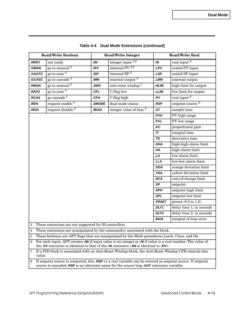
Dual Mode
Advanced Control Blocks 4-13APT Programming Reference (Graphics/Math)
Table 4-4 Dual Mode Extensions (continued)
Read/Write Boolean Read/Write Integer Read/Write Real
.NRDY not ready .IIN integer input 3,6 .IN real input 6
.GMAN go to manual 4 .IPV internal PV 3,6 .LPV scaled PV input
.GAUTO go to auto 4 .ISP internal SP 3 .LSP scaled SP input
.GCASC go to cascade 4 .IMN internal output 3 .LMN internal output
.RMAN go to manual 5 .AWS anti-reset windup 7 .HLIM high limit for output
.RATO go to auto 5 .CFL C-flag low .LLIM low limit for output
.RCAS go cascade 5 .CFH C-flag high .PV real input 6
.REN request enable 5 .DMODE dual mode status .RSP setpoint source 8
.RDIS request disable 5 .IBIAS integer value of bias 3 .ST sample time
.PVH PV high range
.PVL PV low range
.KC proportional gain
.TI integral time
.TD derivative time
.HHA high-high alarm limit
.HA high alarm limit
.LA low alarm limit
.LLA low-low alarm limit
.ODA orange deviation limit
.YDA yellow deviation limit
.RCA rate-of-change limit
.SP setpoint
.SPH setpoint high limit
.SPL setpoint low limit
.PRSET preset (0.0 to 1.0)
.DLY1 delay time 1, in seconds
.DLY2 delay time 2, in seconds
.BIAS integral of loop error
3 These extensions are not supported for S5 controllers.
4 These extensions are manipulated by the command(s) associated with the block.
5 These booleans are APT flags that are manipulated by the Math procedures Latch, Clear, and On.
6 For each input, APT creates .IIN if input value is an integer or .IN if value is a real number. The value ofthe .PV extension is identical to that of the .IN extension (.IIN is identical to .IPV).
7 If a PID block is associated with an Anti-Reset Windup block, the Anti-Reset Windup CFB controls thisvalue.
8 If setpoint source is computed, this .RSP or a real variable can be entered as setpoint source. If setpointsource is cascaded .RSP is an alternate name for the source loop .OUT extension variable.

Feedforward Output Adjust
Advanced Control Blocks4-14 APT Programming Reference (Graphics/Math)
4.4 Feedforward Output Adjust
The feedforward output adjust block uses two independent control blocks, aPID loop and a dynamic simulation block, to drive a single output. Thefunction of the feedforward output adjust block is to incorporate the featuresof a dynamic block and a PID block into a single block so that the output isalways updated correctly. The feedforward output adjust uses the velocityalgorithm where the output spans --100.0 to 100.0.
On each update, the block adds the contribution of the dynamic block.If the output has exceeded a limit, the block sets the output to the limitvalue.
The PID output is then used for further adjustment. If the PID ispushing the block beyond a limit, the output is set to the limit value,and the .AWS (anti-reset windup status) extension is set as explained inChapter 2, “Standard Blocks.”
If the dynamic block is pushing the output beyond a limit while theloop is moving it away, the loop has final control; and the output ismoved away from the limit.
The PID block has control of the output which is updated each loop scan orevery two seconds, whichever is faster.
NOTE: Because of the dynamic portion of the block, the dynamic sampletime should be between 0.5 and 4095.5 seconds in half-second increments.The sample time of the PID loop should match the dynamic sample time.
The ENABLE and DISABLE commands control the dynamic block. (Seepage 4-9.) The PID block responds to the standard PID commands. You canmonitor .FMODE (feedforward mode) to determine the status of the block: 1indicates that the block is executing; 0 indicates that the block is disabled; 3indicates that the block is initializing.
A typical application of the feedforward output adjust block is to reject theeffect of a known, measurable disturbance on the controlled variable. Thedisturbance variable has no default name in the form that you use to definethe block.
Feedforward output adjust blocks are available for Series 505 and S5controllers. They are not supported for the 560/560T controllers.
Overview
Availability

Feedforward Output Adjust
Advanced Control Blocks 4-15APT Programming Reference (Graphics/Math)
Figure 4-7 shows the feedforward output adjust CFB graphic.
FEEDFORWARD OUTPUT ADJUST
P I D
OUT
xxxxxx.WPV
OUT
PVSPSP
xxxxxx
P I D FDFWDOUT. ADJ.
xxxxxx.OUT
DYNAMIC
Block Name: xxxxxx
DV
xxxxxx.PVPV
SP
DV
Figure 4-7 Feedforward Output Adjust CFB Graphic
Figure 4-8 shows the form that you use to define the feedforward outputadjust block. The shaded entries in the form depend on the previousselection. The information on the form is the same as the PID block exceptthat you cannot have associated math. See page 2-9 for process variableinformation, page 2-11 for process setpoint information, page 2-13 for outputinformation, page 2-15 for controller options, and pages 2-21 to 2-23 for PIDcommands and extensions and for a description of the PID options thatapply to the feedforward output adjust block. Also see Section 3.2, “SecondOrder Lead Lag,” Section 3.3, “Second Order Lag,” Section 3.4, “First OrderLead Lag,” and Section 3.5, “First Order Lag,” for a description of thedynamic options that apply to the feedforward output adjust block.
BlockConfiguration

Feedforward Output Adjust
Advanced Control Blocks4-16 APT Programming Reference (Graphics/Math)
Feedforward Output Adjust (continued)
FEEDFORWARD OUTPUT ADJUSTxxxxxx
?F1
ESCCTLsF2
OPTsF3
Name: xxxxxx Description:Loop sample time: 1.0 sec
Algorithm type: VELOCITYPLC address: Automatic User Assigned
{if user assigned} Reserved address:
Process Variable Information ------------------------------------------------------------------------------------------Process variable: xxxxxx.PV S
Low range: 0.0 Alarm dead band: 0.01High range: 1.0 Low low alarm: 0.1Eng. units: __________ Low alarm: 0.2
{if ANALOG INPUT or if PV is scaled integer} High alarm: 0.8High high alarm: 0.9
Rate of change alarm: 1.0
Process Setpoint Information -- -- -- -- -- -- -- -- -- -- -- -- -- -- -- -- -- -- -- -- -- -- -- -- -- --Setpoint source: CASCADED COMPUTED NONE
{if CASCADED} Loop name: <------>{if COMPUTED} Setpoint name: <------>
Minimum setpoint: 0.0Maximum setpoint: 1.0
Yellow(low) deviation alarm: 0.1Orange(high) deviation alarm: 0.2
Controller Options -- -- -- -- -- -- -- -- -- -- -- -- -- -- -- -- -- -- -- -- -- -- -- -- -- -- -- -- -- -- -- --Error algorithm type? NORMAL SQUARED DEADBAND
Reverse acting? [ ]Freeze bias for output out of range? [ ]
Tuning Parameters -- -- -- -- -- -- -- -- -- -- -- -- -- -- -- -- -- -- -- -- -- -- -- -- -- -- -- -- -- -- -- --Loop type: PI P PID I PD
Proportional gain: 1.0Integral time (reset time): 999.99 min
Derivative time (rate): 0.0 minDerivative gain limiting? [ ]
Limiting coefficient: 10.0
Dynamic Function -- -- -- -- -- -- -- -- -- -- -- -- -- -- -- -- -- -- -- -- -- -- -- -- -- -- -- -- -- -- -- -- --Disturbance variable: xxxxxx.WPV
Dynamic sample time: 1.0 secDynamic function type:
LAG LEAD LAG 2ND ORDER LAG 2ND ORDER LEAD LAG
Second Order Lead-Lag -- -- -- -- -- -- -- -- -- -- -- -- -- -- -- -- -- -- -- -- -- -- -- -- -- -- -- -- -- -- -- -- -- --Steady state gain: 0.0 Lead time constant: 5.0
Dead time: 0.0 Time constant: 10.02nd time constant: 20.0
Feedforward Output Adjust -- -- Output Information -- -- -- -- -- -- -- -- -- -- -- -- -- -- --Output name: xxxxxx.OUT S
Limit output between 0% and 100%? [ ]Minimum output(%): 0.0
Maximum output(%): 100.0
-- -- -- -- -- -- -- -- -- -- -- -- -- -- -- -- -- End of Form -- -- -- -- -- -- -- -- -- -- -- -- -- -- -- -- -- --
Series 505 only
Figure 4-8 Feedforward Output Adjust Form

Feedforward Output Adjust
Advanced Control Blocks 4-17APT Programming Reference (Graphics/Math)
Table 4-5 lists the commands that determine the mode of operation for thefeedforward output adjust block. These commands operate the same waythat they do for the PID block. See page 2-21 for PID commands.
Table 4-5 Feedforward Output Adjust Commands
Command Description
AUTOPlaces loop in automatic mode and gets setpoint fromcfb_name.SP.
MANUAL (MAN) Places loop in manual mode; deactivates PID calculation.
CASCADE (CAS) Places loop into cascade mode and gets setpoint from remotesource.
ENABLE (ENA) Turns on, or activates, the dynamic function.
DISABLE (DIS) Turns off, or deactivates, the dynamic function.
Commands andExtensions
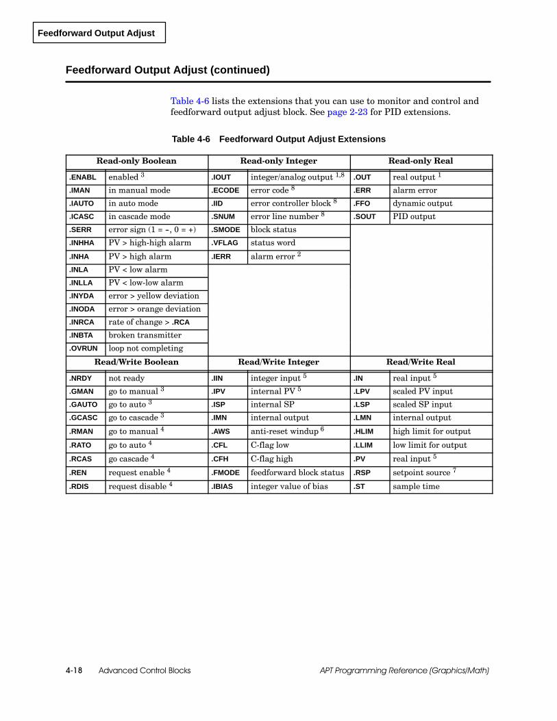
Feedforward Output Adjust
Advanced Control Blocks4-18 APT Programming Reference (Graphics/Math)
Feedforward Output Adjust (continued)
Table 4-6 lists the extensions that you can use to monitor and control andfeedforward output adjust block. See page 2-23 for PID extensions.
Table 4-6 Feedforward Output Adjust Extensions
Read-only Boolean Read-only Integer Read-only Real
.ENABL enabled 3 .IOUT integer/analog output 1,8 .OUT real output 1
.IMAN in manual mode .ECODE error code 8 .ERR alarm error
.IAUTO in auto mode .IID error controller block 8 .FFO dynamic output
.ICASC in cascade mode .SNUM error line number 8 .SOUT PID output
.SERR error sign (1 = --, 0 = +) .SMODE block status
.INHHA PV > high-high alarm .VFLAG status word
.INHA PV > high alarm .IERR alarm error 2
.INLA PV < low alarm
.INLLA PV < low-low alarm
.INYDA error > yellow deviation
.INODA error > orange deviation
.INRCA rate of change > .RCA
.INBTA broken transmitter
.OVRUN loop not completing
Read/Write Boolean Read/Write Integer Read/Write Real
.NRDY not ready .IIN integer input 5 .IN real input 5
.GMAN go to manual 3 .IPV internal PV 5 .LPV scaled PV input
.GAUTO go to auto 3 .ISP internal SP .LSP scaled SP input
.GCASC go to cascade 3 .IMN internal output .LMN internal output
.RMAN go to manual 4 .AWS anti-reset windup 6 .HLIM high limit for output
.RATO go to auto 4 .CFL C-flag low .LLIM low limit for output
.RCAS go cascade 4 .CFH C-flag high .PV real input 5
.REN request enable 4 .FMODE feedforward block status .RSP setpoint source 7
.RDIS request disable 4 .IBIAS integer value of bias .ST sample time

Feedforward Output Adjust
Advanced Control Blocks 4-19APT Programming Reference (Graphics/Math)
Table 4-6 Feedforward Output Adjust Extensions (continued)
Read/Write Real (continued)
.PVH PV high range
.PVL PV low range
.KC proportional gain
.TI integral time
.TD derivative time
.HHA high-high alarm limit
.HA high alarm limit
.LA low alarm limit
.LLA low-low alarm limit
.ODA orange deviation limit
.YDA yellow deviation limit
.RCA rate-of-change limit
.SP setpoint
.SPH setpoint high limit
.SPL setpoint low limit
.GAIN steady-state gain
.TAU1 time constant one
.TAU2 time constant two
.TLEAD lead-time constant
.DTIME dead time
.BIAS integral of loop error
1 For each output, APT creates .IOUT if output value is an integer or .OUT if value is a real number. Theoutputs are read-only variables if the block is in auto or cascade and read/write when the block is manual.
2 The .IERR extension is generated only when a Series 505 Thermocouple or RTD input (8WX version) isconfigured.
3 These extensions are manipulated by the command(s) associated with the block.
4 These booleans are APT flags that are manipulated by the Math procedures Latch, Clear, and On.
5 For each input, APT creates .IIN if input value is an integer or .IN if value is a real number. The value ofthe .PV extension is identical to that of the .IN extension (.IIN is identical to .IPV).
6 If a PID block is associated with an Anti-Reset Windup block, the Anti-Reset Windup CFB controls thisvalue.
7 If setpoint source is computed, this .RSP or a real variable can be entered as setpoint source. If setpointsource is cascaded .RSP is an alternate name for the source loop .OUT extension variable.
8 These extensions are not supported for S5 controllers.

Feedforward Setpoint Adjust
Advanced Control Blocks4-20 APT Programming Reference (Graphics/Math)
4.5 Feedforward Setpoint Adjust
The feedforward setpoint adjust block allows you to insert a dynamic blockbetween the output of a segment of math and the setpoint of a PID loop. Thedynamic block is not required; however, without it, this block has the sameeffect as a PID block with associated math in cascade mode. Associatedmath is also optional, and you must select it on the form if your applicationrequires a math section.
Because the feedforward setpoint adjust CFB operates on the output of theloop, you cannot associate math on the output.
With the dynamic block, the feedforward setpoint adjust block has thefollowing operation.
When the PID goes into cascade mode (.SMODE = 5), the dynamic blockis initialized using the backward initialization algorithm. (The currentoutput becomes the initial simulated output condition, and the initialsimulated input condition is computed as the output divided by thegain.)
After initialization (.SMODE = 6), the block executes the math andsends the output through the dynamic block. The output of the dynamicblock is used by the PID as the setpoint.
Feedforward setpoint adjust blocks are available for Series 505 and S5controllers. They are not supported for the 560/560T controllers.
Overview
Availability

Feedforward Setpoint Adjust
Advanced Control Blocks 4-21APT Programming Reference (Graphics/Math)
Figure 4-9 shows the feedforward setpoint adjust CFB graphic.
FEEDFORWARD SETPOINT ADJUST
P I D
OUT
OUT
PV
xxxxxx
P I D FDFWDS.P. ADJ.
xxxxxx.OUT
DYNAMIC
Block Name: xxxxxx
IN
xxxxxx.PVPV
MATH
xxxxxx.MTHIIN
Figure 4-9 Feedforward Setpoint Adjust CFB Graphic
Figure 4-10 shows the form that you use to define the feedforward setpointadjust block. The shaded entries in the form depend on the previousselection. The information on the form is the same as the PID block exceptthat you cannot have associated math. See page 2-9 for process variableinformation, page 2-11 for process setpoint information, page 2-13 for outputinformation, page 2-15 for controller options, and pages 2-21 to 2-23 for PIDcommands and extensions and for a description of the PID options thatapply to the feedforward setpoint adjust block. Also see Section 3.2, “SecondOrder Lead Lag,” Section 3.3, “Second Order Lag,” Section 3.4, “First OrderLead Lag,” and Section 3.5, “First Order Lag,” for a description of thedynamic options that apply to the feedforward setpoint adjust block.
BlockConfiguration

Feedforward Setpoint Adjust
Advanced Control Blocks4-22 APT Programming Reference (Graphics/Math)
Feedforward Setpoint Adjust (continued)
FEEDFORWARD SETPOINT ADJUSTxxxxxx
?F1
ESCCTLsF2
OPTsF3
Name: xxxxxx Description:Sample time: 1.0 secPLC address: Automatic User Assigned
{if user assigned} Reserved address:
Math Parameters -- -- -- -- -- -- -- -- -- -- -- -- -- -- -- -- -- -- -- -- -- -- -- -- -- -- -- -- -- -- -- -- --Math input name: xxxxxx.MTHI
Math output name: xxxxxx.MTHOAssociate math on cascade? [ ] Press F10 to edit math text
Dynamic Function -- -- -- -- -- -- -- -- -- -- -- -- -- -- -- -- -- -- -- -- -- -- -- -- -- -- -- -- -- -- -- --Dynamic function type:
NONE LAG LEAD LAG 2ND ORDER LAG 2ND ORDER LEAD LAGSecond Order Lead Lag -- -- -- -- -- -- -- -- -- -- -- -- -- -- -- -- -- -- -- -- -- -- -- -- -- -- -- -- --
Steady state gain: 1.0 Lead time constant: 5.0Dead time: 0.0 Time constant: 10.0
2nd time constant: 5.0
Loop Information -- -- -- -- -- -- -- -- -- -- -- -- -- -- -- -- -- -- -- -- -- -- -- -- -- -- -- -- -- -- -- -- --Algorithm type: POSITION VELOCITY
Process Variable Information -- -- -- -- -- -- -- -- -- -- -- -- -- -- -- -- -- -- -- -- -- -- -- -- -- -- --Process variable: xxxxxx.PV S
Low range: 0.0 Alarm dead band: 0.01High range: 1.0 Low low alarm: 0.1Eng. units: __________ Low alarm: 0.2
{if ANALOG INPUT or if PV is scaled integer} High alarm: 0.8High high alarm: 0.9
Rate of change alarm: 1.0
Process Setpoint Information -- -- -- -- -- -- -- -- -- -- -- -- -- -- -- -- -- -- -- -- -- -- -- -- -- -- --Setpoint source: COMPUTED
Minimum setpoint: 0.0Maximum setpoint: 1.0
Yellow(low) deviation alarm: 0.1Orange(high) deviation alarm: 0.2
Output Information -- -- -- -- -- -- -- -- -- -- -- -- -- -- -- -- -- -- -- -- -- -- -- -- -- -- -- -- -- -- -- --Output name: xxxxxx.OUT S
Limit output between 0% and 100%? [ ]Minimum output(%): 0.0
Maximum output(%): 100.0
Controller Options -- -- -- -- -- -- -- -- -- -- -- -- -- -- -- -- -- -- -- -- -- -- -- -- -- -- -- -- -- -- -- --Error algorithm type? NORMAL SQUARED DEADBAND
Reverse acting? [ ]Freeze bias for output out of range? [ ]
Tuning Parameters -- -- -- -- -- -- -- -- -- -- -- -- -- -- -- -- -- -- -- -- -- -- -- -- -- -- -- -- -- -- -- --Loop type: PI P PID I PD
Proportional gain: 1.0Integral time (reset time): 999.99 min
Derivative time (rate): 0.0 minDerivative gain limiting? [ ]
Limiting coefficient: 10.0
-- -- -- -- -- -- -- -- -- -- -- -- -- -- -- -- -- End of Form -- -- -- -- -- -- -- -- -- -- -- -- -- -- -- -- -- --
Series 505 only
Figure 4-10 Feedforward Setpoint Adjust Form

Feedforward Setpoint Adjust
Advanced Control Blocks 4-23APT Programming Reference (Graphics/Math)
Table 4-7 lists the commands that determine the mode of operation for thefeedforward setpoint adjust block. These commands operate the same waythat they do for the PID block. See page 2-21 for PID commands.
Table 4-7 Feedforward Setpoint Adjust Commands
Command Description
AUTOPlaces loop in automatic mode and gets setpoint fromcfb_name.SP.
MANUAL (MAN) Places loop in manual mode; deactivates PID calculation.
CASCADE (CAS) Places loop into cascade mode.
Table 4-8 lists the extensions that you can use to monitor and control afeedforward setpoint adjust block. See page 2-23 for PID extensions.
Table 4-8 Feedforward Setpoint Adjust Extensions
Read-only Boolean Read-only Integer Read-only Real
.IMAN in manual mode .IOUT integer/analog output 1,8 .OUT real output 1
.IAUTO in auto mode .ECODE error code 8 .ERR alarm error
.ICASC in cascade mode .IID error controller block 8
.SERR error sign (1 = --, 0 = +) .SNUM error line number 8
.INHHA PV > high-high alarm .SMODE block status
.INHA PV > high alarm .VFLAG status word
.INLA PV < low alarm .IERR alarm error 2
.INLLA PV < low-low alarm
.INYDA error > yellow deviation
.INODA error > orange deviation
.INRCA rate of change > .RCA
.INBTA broken transmitter 8
.OVRUN loop not completingRead/Write Boolean Read/Write Integer Read/Write Real
.NRDY not ready .IIN integer input 5,8 .IN real input 5
.GMAN go to manual 3 .IPV internal PV 5,8 .MTHI math block input
.GAUTO go to auto 3 .ISP internal SP 8 .MTHO math block output
.GCASC go to cascade 3 .IMN internal output 8 .LPV scaled PV input
.RMAN go to manual 4 .AWS anti-reset windup 6 .LSP scaled SP input
.RATO go to auto 4 .CFL C-flag low .LMN internal output
.RCAS go cascade 4 .CFH C-flag high .HLIM high limit for output.IBIAS integer value of bias 8 .LLIM low limit for output
Commands andExtensions

Feedforward Setpoint Adjust
Advanced Control Blocks4-24 APT Programming Reference (Graphics/Math)
Feedforward Setpoint Adjust (continued)
Table 4-8 Feedforward Setpoint Adjust Extensions (continued)
Read/Write Real (continued)
.RSP setpoint source 7
.ST sample time
.PV real input 5
.PVH PV high range
.PVL PV low range
.KC proportional time
.TI integral time
.TD derivative time
.HHA high-high alarm limit
.HA high alarm limit
.LA low alarm limit
.LLA low-low alarm limit
.ODA orange deviation limit
.YDA yellow deviation limit
.RCA rate-of-change limit
.SP setpoint
.SPH setpoint high limit
.SPL setpoint low limit
.GAIN steady-state gain
.TAU1 time constant one
.TAU2 time constant two
.TLEAD lead-time constant
.DTIME dead time
.BIAS integral of loop error
1 For each output, APT creates .IOUT if output value is an integer or .OUT if value is a real number. Theoutputs are read-only variables if the block is in auto or cascade and read/write when the block is manual.
2 The .IERR extension is generated only when a Series 505 Thermocouple or RTD input (8WX version) isconfigured.
3 These extensions are manipulated by the command(s) associated with the block.5 For each input, APT creates .IIN if input value is an integer or .IN if value is a real number. The value of
the .PV extension is identical to that of the .IN extension (.IIN is identical to .IPV).6 If a PID block is associated with an Anti-Reset Windup block, the Anti-Reset Windup CFB controls this
value.
7 If setpoint source is computed, this .RSP or a real variable can be entered as setpoint source. If setpointsource is cascaded .RSP is an alternate name for the source loop .OUT extension variable.
8 These extensions are not supported for S5 controllers.

Ratio Station
Advanced Control Blocks 4-25APT Programming Reference (Graphics/Math)
4.6 Ratio Station
The ratio station block is used to keep a constant ratio between two processvariables. The setpoint to the block is the ratio that you want to maintainbetween a controlled variable and an uncontrolled (wild) process variable.
To ensure a bumpless transfer, the algorithm keeps the setpoint and theoutput unchanged during the transition from manual or automatic tocascade mode. Thereafter, the loop uses the following formula to computethe loop setpoint and bring the process variable to the appropriate value:
setpoint = (ratio setpoint × wild variable) + offset
When you configure the analog input for the ratio station block, do notselect the No Scaling option for the uncontrolled process variable for a ratiostation block. You can, however, select No Scaling for the controlled processvariable.
Ratio station blocks are available for Series 505 and S5 controllers. They arenot supported for the 560/560T controllers.
Figure 4-11 shows the graphic for a ratio station CFB.
RATIO STATION
P I D
OUT
SP
xxxxxx
OUT
WPVSPSP
xxxxxx
P I D RATIOSTATION
xxxxxx.OUT
OFFSET
A X B
Block Name: xxxxxx
PV
xxxxxx.PV
xxxxxx.WPVWPV
PV
uncontrolledvariable
ratiosetpoint
controlledvariable
loopsetpoint
+
+
xxxxxx.RSP
Figure 4-11 Ratio Station Graphic
Figure 4-12 shows the form that you use to define the ratio station block.The shaded entries in the form depend on the previous selection. Theinformation on the form is the same as the PID block except that you cannothave associated math.
Overview
Availability
BlockConfiguration

Ratio Station
Advanced Control Blocks4-26 APT Programming Reference (Graphics/Math)
Ratio Station (continued)
See page 2-9 for process variable information, page 2-11 for process setpointinformation, page 2-13 for output information, page 2-15 for controlleroptions, and pages 2-21 to 2-23 for PID commands and extensions and for adescription of the PID options that apply to the the ratio station block.
RATIO STATIONxxxxxx
?F1
ESCCTLsF2
OPTsF3
Name: xxxxxx Description:Sample time: 1.0 secPLC address: Automatic User Assigned
{if user assigned} Reserved address:
Wild Process Variable Information -- -- -- -- -- -- -- -- -- -- -- -- -- -- -- -- -- -- -- -- -- -- -- --Wild process variable: xxxxxx.WPV S
Low range: 0.0High range: 1.0
Loop Information -- -- -- -- -- -- -- -- -- -- -- -- -- -- -- -- -- -- -- -- -- -- -- -- -- -- -- -- -- -- -- -- --Algorithm type: POSITION
Loop Process Variable Information -- -- -- -- -- -- -- -- -- -- -- -- -- -- -- -- -- -- -- -- -- -- --Process variable: xxxxxx.PV S
Low range: 0.0 Alarm dead band: 0.01High range: 1.0 Low low alarm: 0.1Eng. units: __________ Low alarm: 0.2
{if ANALOG INPUT or if PV is scaled integer} High alarm: 0.8High high alarm: 0.9
Rate of change alarm: 1.0
Process Setpoint Information -- -- -- -- -- -- -- -- -- -- -- -- -- -- -- -- -- -- -- -- -- -- -- -- -- -- --Setpoint source: COMPUTEDSetpoint name: xxxxxx.RSP
Offset value: 0.0Minimum setpoint 0.0
Maximum setpoint: 1.0Yellow(low) deviation alarm: 0.1
Orange(high) deviation alarm: 0.2
Output Information -- -- -- -- -- -- -- -- -- -- -- -- -- -- -- -- -- -- -- -- -- -- -- -- -- -- -- -- -- -- -- --Output name: xxxxxx.OUT S
Limit output between 0% and 100%? [X]Minimum output(%): 0.0Maximum output(%: 100.0
Controller Options -- -- -- -- -- -- -- -- -- -- -- -- -- -- -- -- -- -- -- -- -- -- -- -- -- -- -- -- -- -- -- --Error algorithm type? NORMAL SQUARED DEADBAND
Reverse acting? [ ]Freeze bias for output out of range? [ ]
Tuning Parameters -- -- -- -- -- -- -- -- -- -- -- -- -- -- -- -- -- -- -- -- -- -- -- -- -- -- -- -- -- -- -- --Loop type: PI P PID I PD
Proportional gain: 1.0Integral time (reset time): 999.99 min
Derivative time (rate): 0.0 minDerivative gain limiting? [X]
Limiting coefficient: 1 0.0
-- -- -- -- -- -- -- -- -- -- -- -- -- -- -- -- -- End of Form -- -- -- -- -- -- -- -- -- -- -- -- -- -- -- -- -- --
Series 505 only
Figure 4-12 Ratio Station Form

Ratio Station
Advanced Control Blocks 4-27APT Programming Reference (Graphics/Math)
Table 4-9 lists the commands that determine the mode of operation for theratio station block. These commands operate in the same way that they dofor the PID block. See page 2-21 for PID commands.
Table 4-9 Ratio Station Commands
Command Description
AUTOPlaces loop in automatic mode and gets setpoint fromcfb_name.SP.
MANUAL (MAN) Places loop in manual mode; deactivates PID calculation.
CASCADE (CAS) Places loop into cascade mode and gets setpoint from remotesource.
Table 4-10 lists the extensions that you can use to monitor and control andratio station block. See page 2-23 for PID extensions.
Table 4-10 Ratio Station Extensions
Read-only Boolean Read-only Integer Read-only Real
.IMAN in manual mode .IOUT integer/analog output 1,3 .OUT real output 1
.IAUTO in auto mode .ECODE error code 3 .ERR alarm error
.ICASC in cascade mode .IID error controller block 3 .RATIO ratio of inputs
.SERR error sign (1 = --, 0 = +) .SNUM error line number 3
.INHHA PV > high-high alarm .SMODE block status
.INHA PV > high alarm .VFLAG status word
.INLA PV < low alarm .IERR alarm error 2
.INLLA PV < low-low alarm
.INYDA error > yellow deviation
.INODA error > orange deviation
.INRCA rate of change > .RCA
.INBTA broken transmitter 3
.OVRUN loop not completing1 For each output, APT creates .IOUT if output value is an integer or .OUT if value is a real number. The
outputs are read-only variables if the block is in auto or cascade and read/write when the block is manual.
2 The .IERR extension is generated only when a Series 505 Thermocouple or RTD input (8WX version) isconfigured.
3 These extensions are not supported for S5 controllers.
Commands andExtensions
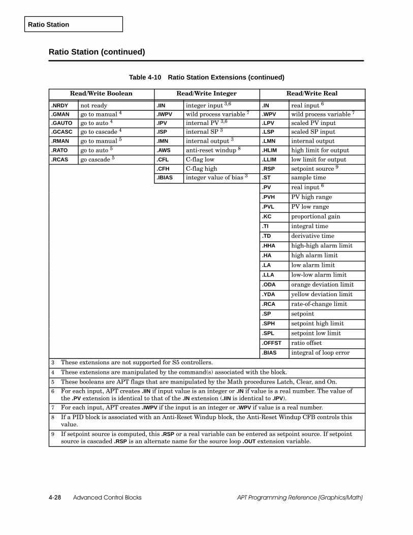
Ratio Station
Advanced Control Blocks4-28 APT Programming Reference (Graphics/Math)
Ratio Station (continued)
Table 4-10 Ratio Station Extensions (continued)
Read/Write Boolean Read/Write Integer Read/Write Real
.NRDY not ready .IIN integer input 3,6 .IN real input 6
.GMAN go to manual 4 .IWPV wild process variable 7 .WPV wild process variable 7
.GAUTO go to auto 4 .IPV internal PV 3,6 .LPV scaled PV input
.GCASC go to cascade 4 .ISP internal SP 3 .LSP scaled SP input
.RMAN go to manual 5 .IMN internal output 3 .LMN internal output
.RATO go to auto 5 .AWS anti-reset windup 8 .HLIM high limit for output
.RCAS go cascade 5 .CFL C-flag low .LLIM low limit for output.CFH C-flag high .RSP setpoint source 9
.IBIAS integer value of bias 3 .ST sample time
.PV real input 6
.PVH PV high range
.PVL PV low range
.KC proportional gain
.TI integral time
.TD derivative time
.HHA high-high alarm limit
.HA high alarm limit
.LA low alarm limit
.LLA low-low alarm limit
.ODA orange deviation limit
.YDA yellow deviation limit
.RCA rate-of-change limit
.SP setpoint
.SPH setpoint high limit
.SPL setpoint low limit
.OFFST ratio offset
.BIAS integral of loop error
3 These extensions are not supported for S5 controllers.
4 These extensions are manipulated by the command(s) associated with the block.
5 These booleans are APT flags that are manipulated by the Math procedures Latch, Clear, and On.6 For each input, APT creates .IIN if input value is an integer or .IN if value is a real number. The value of
the .PV extension is identical to that of the .IN extension (.IIN is identical to .IPV).7 For each input, APT creates .IWPV if the input is an integer or .WPV if value is a real number.
8 If a PID block is associated with an Anti-Reset Windup block, the Anti-Reset Windup CFB controls thisvalue.
9 If setpoint source is computed, this .RSP or a real variable can be entered as setpoint source. If setpointsource is cascaded .RSP is an alternate name for the source loop .OUT extension variable.
Limiter Blocks 5-1APT Programming Reference (Graphics/Math)
Chapter 5
Limiter Blocks
5.1 Understanding Limiter Blocks 5-2. . . . . . . . . . . . . . . . . . . . . . . . . . . . . . . . . . . . . . . . . . . . . . . . . . .Overview 5-2. . . . . . . . . . . . . . . . . . . . . . . . . . . . . . . . . . . . . . . . . . . . . . . . . . . . . . . . . . . . . . . . . . . . . . .Availability 5-2. . . . . . . . . . . . . . . . . . . . . . . . . . . . . . . . . . . . . . . . . . . . . . . . . . . . . . . . . . . . . . . . . . . . . .Inputs and Outputs 5-2. . . . . . . . . . . . . . . . . . . . . . . . . . . . . . . . . . . . . . . . . . . . . . . . . . . . . . . . . . . . . .Enabling and Disabling Blocks 5-2. . . . . . . . . . . . . . . . . . . . . . . . . . . . . . . . . . . . . . . . . . . . . . . . . . . .
5.2 Output Limiter 5-3. . . . . . . . . . . . . . . . . . . . . . . . . . . . . . . . . . . . . . . . . . . . . . . . . . . . . . . . . . . . . . . . .Overview 5-3. . . . . . . . . . . . . . . . . . . . . . . . . . . . . . . . . . . . . . . . . . . . . . . . . . . . . . . . . . . . . . . . . . . . . . .Availability 5-3. . . . . . . . . . . . . . . . . . . . . . . . . . . . . . . . . . . . . . . . . . . . . . . . . . . . . . . . . . . . . . . . . . . . . .Block Configuration 5-3. . . . . . . . . . . . . . . . . . . . . . . . . . . . . . . . . . . . . . . . . . . . . . . . . . . . . . . . . . . . . .Commands and Extensions 5-4. . . . . . . . . . . . . . . . . . . . . . . . . . . . . . . . . . . . . . . . . . . . . . . . . . . . . . .
5.3 Rate Limiter 5-5. . . . . . . . . . . . . . . . . . . . . . . . . . . . . . . . . . . . . . . . . . . . . . . . . . . . . . . . . . . . . . . . . . .Overview 5-5. . . . . . . . . . . . . . . . . . . . . . . . . . . . . . . . . . . . . . . . . . . . . . . . . . . . . . . . . . . . . . . . . . . . . . .Availability 5-5. . . . . . . . . . . . . . . . . . . . . . . . . . . . . . . . . . . . . . . . . . . . . . . . . . . . . . . . . . . . . . . . . . . . . .Block Configuration 5-6. . . . . . . . . . . . . . . . . . . . . . . . . . . . . . . . . . . . . . . . . . . . . . . . . . . . . . . . . . . . . .Commands and Extensions 5-7. . . . . . . . . . . . . . . . . . . . . . . . . . . . . . . . . . . . . . . . . . . . . . . . . . . . . . .

Limiter Blocks5-2 APT Programming Reference (Graphics/Math)
5.1 Understanding Limiter Blocks
The APT limiter blocks provide a means to limit the value of an output thatis based on an input. Two basic types of limiter blocks are available:
The output-limiter block checks for an out-of-range input and keeps theoutput of the block within the high and low limits that you specify.
The rate-limiter block can be used as a ramp function to change theoutput at a specified rate until it is equal to the input.
Limiter blocks are available for Series 505 and S5 controllers. They are notsupported for the 560/560T controllers.
The input to a limiter block can be a real number, an integer, or an analoginput.
The output responds to the input. If the output is an analog value, APTassumes that the input is a real number limited to the range of 0.0 to 1.0,and automatically scales the output to the correct format (zero offset, 20%bias, or bipolar). If an input is outside this range, the output is set to themaximum or minimum value of the subtype.
All limiter CFBs must be activated with the ENABLE command or with anassignment statement that sets the .ENABL extension to true. SeeFigure 5-1. Limiter blocks can also be enabled from an assignmentstatement in a math CFB.
cfb_name.ENABL := true;Enable cfb_name;
S3 ENABLE cfb_name;A
xxxxxx
MATH
B C D
E F G H
Figure 5-1 Enabling a Limiter CFB
To deactivate the block, use the DISABLE command with the block name orset the .ENABL extension to false.
All limiter blocks have a boolean extension (.NRDY) that you can use tointerlock the execution of the block to some external conditions.
If you set the .NRDY extension to true, the block is forced to the disabledstate.
To return the block to the enabled state you must not only set the.NRDY extension to false but also re-enable the block with a commandor an assignment statement.
Overview
Availability
Inputs and Outputs
Enabling andDisabling Blocks
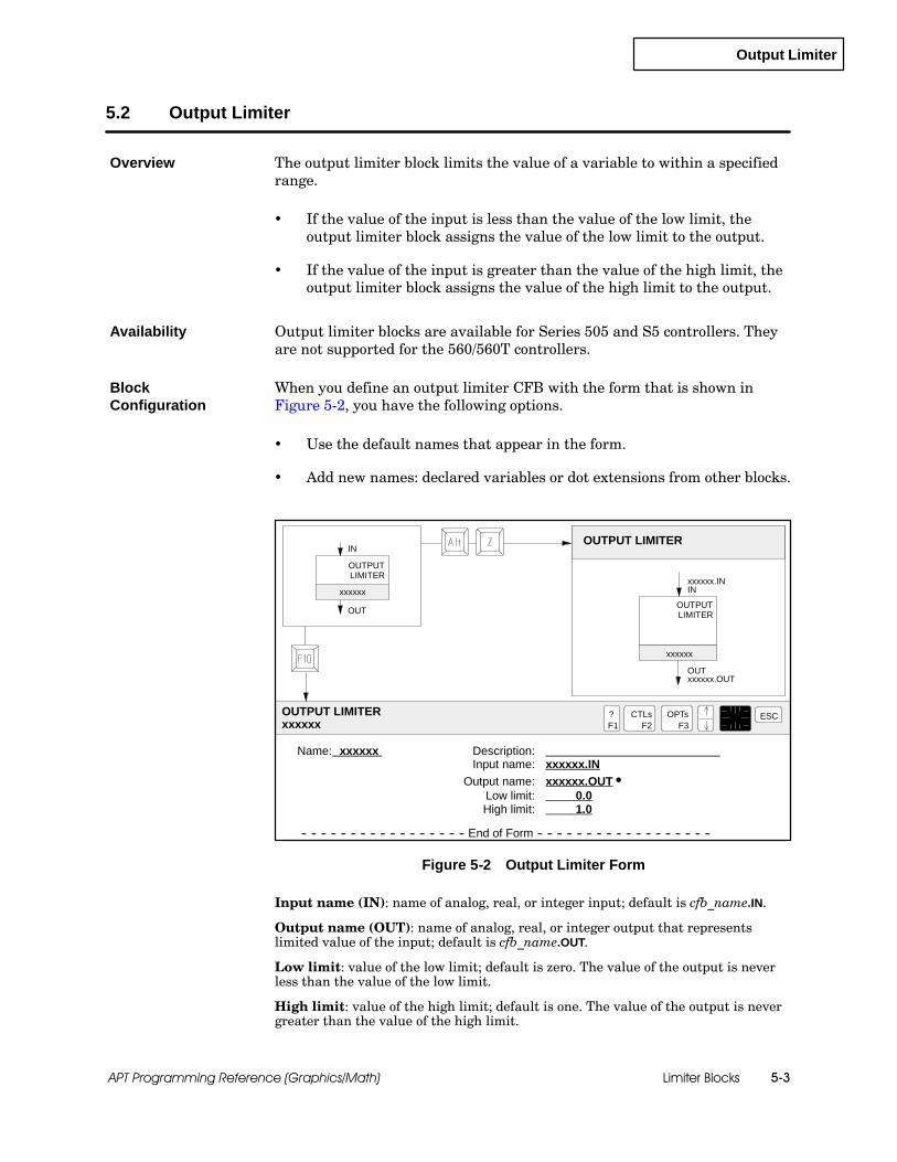
Output Limiter
Limiter Blocks 5-3APT Programming Reference (Graphics/Math)
5.2 Output Limiter
The output limiter block limits the value of a variable to within a specifiedrange.
If the value of the input is less than the value of the low limit, theoutput limiter block assigns the value of the low limit to the output.
If the value of the input is greater than the value of the high limit, theoutput limiter block assigns the value of the high limit to the output.
Output limiter blocks are available for Series 505 and S5 controllers. Theyare not supported for the 560/560T controllers.
When you define an output limiter CFB with the form that is shown inFigure 5-2, you have the following options.
Use the default names that appear in the form.
Add new names: declared variables or dot extensions from other blocks.
Name: xxxxxx Description:Input name: xxxxxx.IN
Output name: xxxxxx.OUT SLow limit: 0.0High limit: 1.0
-- -- -- -- -- -- -- -- -- -- -- -- -- -- -- -- -- End of Form -- -- -- -- -- -- -- -- -- -- -- -- -- -- -- -- -- --
OUT
OUTPUT LIMITER
xxxxxx.OUT
xxxxxx.ININ
OUTPUT LIMITERxxxxxx
?F1
ESCCTLsF2
OPTsF3
OUT
IN
xxxxxx
xxxxxxOUTPUTLIMITER
OUTPUTLIMITER
Figure 5-2 Output Limiter Form
Input name (IN): name of analog, real, or integer input; default is cfb_name.IN.
Output name (OUT): name of analog, real, or integer output that representslimited value of the input; default is cfb_name.OUT.
Low limit: value of the low limit; default is zero. The value of the output is neverless than the value of the low limit.
High limit: value of the high limit; default is one. The value of the output is nevergreater than the value of the high limit.
Overview
Availability
BlockConfiguration

Output Limiter
Limiter Blocks5-4 APT Programming Reference (Graphics/Math)
Output Limiter (continued)
Table 5-1 lists the commands that determine the mode of operation for theoutput limiter block.
Table 5-1 Output Limiter Commands
Command Description
ENABLE (ENA) Turns on, or activates, the block.
DISABLE (DIS) Turns off, or deactivates, the block.
Table 5-2 lists the extensions that you can use to monitor and control aoutput limiter block.
Table 5-2 Output Limiter Extensions
Read-only Boolean Read-only Integer Read-only Real
.ENABLD enabled .IOUT integer output 3 .OUT output 3
.ECODE error code 4
.IID error controller block 4
.SNUM error line number 4
Read/Write Boolean Read/Write Integer Read/Write Real
.ENABL enable 1 .IIN integer input 5 .IN input 5
.NRDY not ready .HLIM high limit value
.REN request enable 2 .LLIM low limit value
.RDIS request disable 2
1 This extension is manipulated by the command(s) associated with the block.
2 These booleans are APT flags that are manipulated by the Math procedures Latch, Clear, and On.
3 For each output, APT creates .IOUT if output value is an integer or .OUT if value is a real number. Theoutputs are read-only variables if the block is enabled and read/write when the block is disabled.
4 These extensions are Series 505 error codes only and do not contain the error codes for S5 controllers.
5 For each input, APT creates .IIN if input value is an integer or .IN if value is a real number.
Commands andExtensions
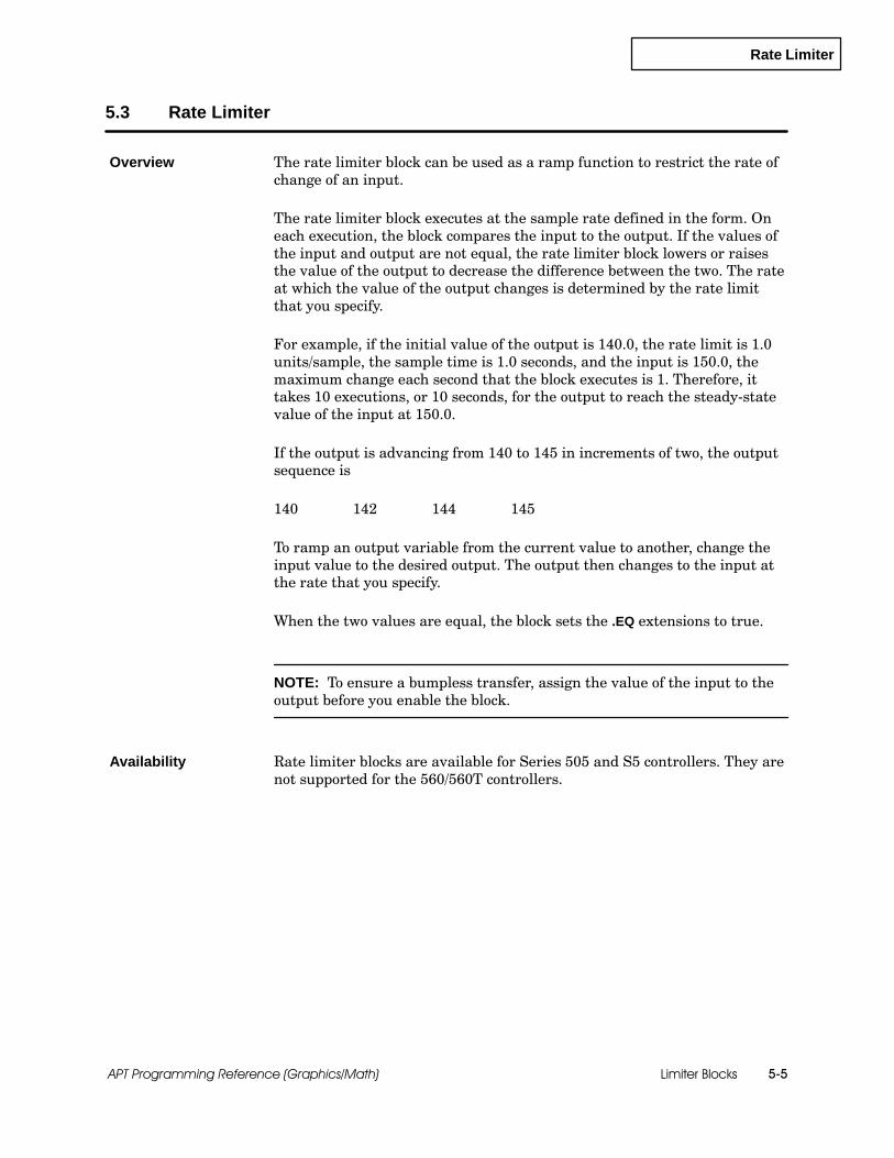
Rate Limiter
Limiter Blocks 5-5APT Programming Reference (Graphics/Math)
5.3 Rate Limiter
The rate limiter block can be used as a ramp function to restrict the rate ofchange of an input.
The rate limiter block executes at the sample rate defined in the form. Oneach execution, the block compares the input to the output. If the values ofthe input and output are not equal, the rate limiter block lowers or raisesthe value of the output to decrease the difference between the two. The rateat which the value of the output changes is determined by the rate limitthat you specify.
For example, if the initial value of the output is 140.0, the rate limit is 1.0units/sample, the sample time is 1.0 seconds, and the input is 150.0, themaximum change each second that the block executes is 1. Therefore, ittakes 10 executions, or 10 seconds, for the output to reach the steady-statevalue of the input at 150.0.
If the output is advancing from 140 to 145 in increments of two, the outputsequence is
140 142 144 145
To ramp an output variable from the current value to another, change theinput value to the desired output. The output then changes to the input atthe rate that you specify.
When the two values are equal, the block sets the .EQ extensions to true.
NOTE: To ensure a bumpless transfer, assign the value of the input to theoutput before you enable the block.
Rate limiter blocks are available for Series 505 and S5 controllers. They arenot supported for the 560/560T controllers.
Overview
Availability

Rate Limiter
Limiter Blocks5-6 APT Programming Reference (Graphics/Math)
Rate Limiter (continued)
When you define a rate limiter CFB with the form that is shown inFigure 5-3, you have the following options.
You can use the default names that appear in the form.
You can add new names: declared variables or dot extensions fromother blocks.
Name: xxxxxx Description:Input name: xxxxxx.IN
Output name: xxxxxx.OUTSRate limit: 1.0 units/sample
Sample rate: 1.0 sec
-- -- -- -- -- -- -- -- -- -- -- -- -- -- -- -- -- End of Form -- -- -- -- -- -- -- -- -- -- -- -- -- -- -- -- -- --
OUT
RATE LIMITER
xxxxxx.OUT
xxxxxx.ININ
RATE LIMITERxxxxxx
?F1
ESCCTLsF2
OPTsF3
OUT
IN
xxxxxx
xxxxxxRATE
LIMITER
RATELIMITER
Figure 5-3 Rate Limiter Form
Input name (IN): name of analog, real, or integer input; default is cfb_name.IN.
Output name (OUT): name of analog, real, or integer output; default iscfb_name.OUT.
Rate limit: rate of change, in units per sample rate; contains maximum change thatis allowed in the output per execution; default is 1.
Sample rate: specifies, in seconds, how often the block is executed; default is 1. Therange is 0.5 to 4095.0 seconds.
BlockConfiguration
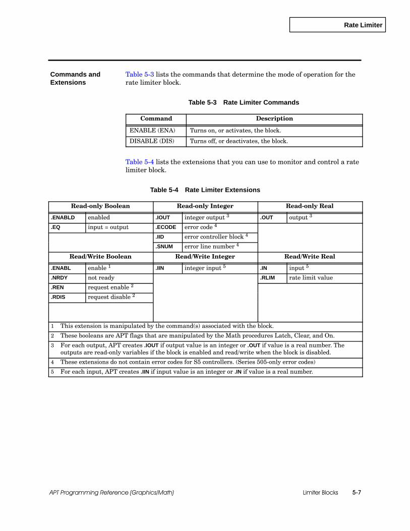
Rate Limiter
Limiter Blocks 5-7APT Programming Reference (Graphics/Math)
Table 5-3 lists the commands that determine the mode of operation for therate limiter block.
Table 5-3 Rate Limiter Commands
Command Description
ENABLE (ENA) Turns on, or activates, the block.
DISABLE (DIS) Turns off, or deactivates, the block.
Table 5-4 lists the extensions that you can use to monitor and control a ratelimiter block.
Table 5-4 Rate Limiter Extensions
Read-only Boolean Read-only Integer Read-only Real
.ENABLD enabled .IOUT integer output 3 .OUT output 3
.EQ input = output .ECODE error code 4
.IID error controller block 4
.SNUM error line number 4
Read/Write Boolean Read/Write Integer Read/Write Real
.ENABL enable 1 .IIN integer input 5 .IN input 5
.NRDY not ready .RLIM rate limit value
.REN request enable 2
.RDIS request disable 2
1 This extension is manipulated by the command(s) associated with the block.
2 These booleans are APT flags that are manipulated by the Math procedures Latch, Clear, and On.
3 For each output, APT creates .IOUT if output value is an integer or .OUT if value is a real number. Theoutputs are read-only variables if the block is enabled and read/write when the block is disabled.
4 These extensions do not contain error codes for S5 controllers. (Series 505-only error codes)
5 For each input, APT creates .IIN if input value is an integer or .IN if value is a real number.
Commands andExtensions

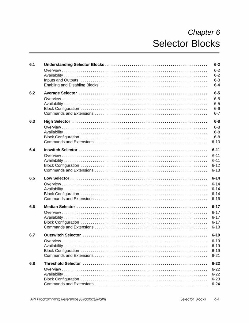
Selector Blocks 6-1APT Programming Reference (Graphics/Math)
Chapter 6
Selector Blocks
6.1 Understanding Selector Blocks 6-2. . . . . . . . . . . . . . . . . . . . . . . . . . . . . . . . . . . . . . . . . . . . . . . . . .Overview 6-2. . . . . . . . . . . . . . . . . . . . . . . . . . . . . . . . . . . . . . . . . . . . . . . . . . . . . . . . . . . . . . . . . . . . . . .Availability 6-2. . . . . . . . . . . . . . . . . . . . . . . . . . . . . . . . . . . . . . . . . . . . . . . . . . . . . . . . . . . . . . . . . . . . . .Inputs and Outputs 6-3. . . . . . . . . . . . . . . . . . . . . . . . . . . . . . . . . . . . . . . . . . . . . . . . . . . . . . . . . . . . . .Enabling and Disabling Blocks 6-4. . . . . . . . . . . . . . . . . . . . . . . . . . . . . . . . . . . . . . . . . . . . . . . . . . . .
6.2 Average Selector 6-5. . . . . . . . . . . . . . . . . . . . . . . . . . . . . . . . . . . . . . . . . . . . . . . . . . . . . . . . . . . . . . .Overview 6-5. . . . . . . . . . . . . . . . . . . . . . . . . . . . . . . . . . . . . . . . . . . . . . . . . . . . . . . . . . . . . . . . . . . . . . .Availability 6-5. . . . . . . . . . . . . . . . . . . . . . . . . . . . . . . . . . . . . . . . . . . . . . . . . . . . . . . . . . . . . . . . . . . . . .Block Configuration 6-6. . . . . . . . . . . . . . . . . . . . . . . . . . . . . . . . . . . . . . . . . . . . . . . . . . . . . . . . . . . . . .Commands and Extensions 6-7. . . . . . . . . . . . . . . . . . . . . . . . . . . . . . . . . . . . . . . . . . . . . . . . . . . . . . .
6.3 High Selector 6-8. . . . . . . . . . . . . . . . . . . . . . . . . . . . . . . . . . . . . . . . . . . . . . . . . . . . . . . . . . . . . . . . . .Overview 6-8. . . . . . . . . . . . . . . . . . . . . . . . . . . . . . . . . . . . . . . . . . . . . . . . . . . . . . . . . . . . . . . . . . . . . . .Availability 6-8. . . . . . . . . . . . . . . . . . . . . . . . . . . . . . . . . . . . . . . . . . . . . . . . . . . . . . . . . . . . . . . . . . . . . .Block Configuration 6-8. . . . . . . . . . . . . . . . . . . . . . . . . . . . . . . . . . . . . . . . . . . . . . . . . . . . . . . . . . . . . .Commands and Extensions 6-10. . . . . . . . . . . . . . . . . . . . . . . . . . . . . . . . . . . . . . . . . . . . . . . . . . . . . . .
6.4 Inswitch Selector 6-11. . . . . . . . . . . . . . . . . . . . . . . . . . . . . . . . . . . . . . . . . . . . . . . . . . . . . . . . . . . . . . .Overview 6-11. . . . . . . . . . . . . . . . . . . . . . . . . . . . . . . . . . . . . . . . . . . . . . . . . . . . . . . . . . . . . . . . . . . . . . .Availability 6-11. . . . . . . . . . . . . . . . . . . . . . . . . . . . . . . . . . . . . . . . . . . . . . . . . . . . . . . . . . . . . . . . . . . . . .Block Configuration 6-12. . . . . . . . . . . . . . . . . . . . . . . . . . . . . . . . . . . . . . . . . . . . . . . . . . . . . . . . . . . . . .Commands and Extensions 6-13. . . . . . . . . . . . . . . . . . . . . . . . . . . . . . . . . . . . . . . . . . . . . . . . . . . . . . .
6.5 Low Selector 6-14. . . . . . . . . . . . . . . . . . . . . . . . . . . . . . . . . . . . . . . . . . . . . . . . . . . . . . . . . . . . . . . . . . .Overview 6-14. . . . . . . . . . . . . . . . . . . . . . . . . . . . . . . . . . . . . . . . . . . . . . . . . . . . . . . . . . . . . . . . . . . . . . .Availability 6-14. . . . . . . . . . . . . . . . . . . . . . . . . . . . . . . . . . . . . . . . . . . . . . . . . . . . . . . . . . . . . . . . . . . . . .Block Configuration 6-14. . . . . . . . . . . . . . . . . . . . . . . . . . . . . . . . . . . . . . . . . . . . . . . . . . . . . . . . . . . . . .Commands and Extensions 6-16. . . . . . . . . . . . . . . . . . . . . . . . . . . . . . . . . . . . . . . . . . . . . . . . . . . . . . .
6.6 Median Selector 6-17. . . . . . . . . . . . . . . . . . . . . . . . . . . . . . . . . . . . . . . . . . . . . . . . . . . . . . . . . . . . . . . .Overview 6-17. . . . . . . . . . . . . . . . . . . . . . . . . . . . . . . . . . . . . . . . . . . . . . . . . . . . . . . . . . . . . . . . . . . . . . .Availability 6-17. . . . . . . . . . . . . . . . . . . . . . . . . . . . . . . . . . . . . . . . . . . . . . . . . . . . . . . . . . . . . . . . . . . . . .Block Configuration 6-17. . . . . . . . . . . . . . . . . . . . . . . . . . . . . . . . . . . . . . . . . . . . . . . . . . . . . . . . . . . . . .Commands and Extensions 6-18. . . . . . . . . . . . . . . . . . . . . . . . . . . . . . . . . . . . . . . . . . . . . . . . . . . . . . .
6.7 Outswitch Selector 6-19. . . . . . . . . . . . . . . . . . . . . . . . . . . . . . . . . . . . . . . . . . . . . . . . . . . . . . . . . . . . .Overview 6-19. . . . . . . . . . . . . . . . . . . . . . . . . . . . . . . . . . . . . . . . . . . . . . . . . . . . . . . . . . . . . . . . . . . . . . .Availability 6-19. . . . . . . . . . . . . . . . . . . . . . . . . . . . . . . . . . . . . . . . . . . . . . . . . . . . . . . . . . . . . . . . . . . . . .Block Configuration 6-19. . . . . . . . . . . . . . . . . . . . . . . . . . . . . . . . . . . . . . . . . . . . . . . . . . . . . . . . . . . . . .Commands and Extensions 6-21. . . . . . . . . . . . . . . . . . . . . . . . . . . . . . . . . . . . . . . . . . . . . . . . . . . . . . .
6.8 Threshold Selector 6-22. . . . . . . . . . . . . . . . . . . . . . . . . . . . . . . . . . . . . . . . . . . . . . . . . . . . . . . . . . . . .Overview 6-22. . . . . . . . . . . . . . . . . . . . . . . . . . . . . . . . . . . . . . . . . . . . . . . . . . . . . . . . . . . . . . . . . . . . . . .Availability 6-22. . . . . . . . . . . . . . . . . . . . . . . . . . . . . . . . . . . . . . . . . . . . . . . . . . . . . . . . . . . . . . . . . . . . . .Block Configuration 6-23. . . . . . . . . . . . . . . . . . . . . . . . . . . . . . . . . . . . . . . . . . . . . . . . . . . . . . . . . . . . . .Commands and Extensions 6-24. . . . . . . . . . . . . . . . . . . . . . . . . . . . . . . . . . . . . . . . . . . . . . . . . . . . . . .

Selector Blocks6-2 APT Programming Reference (Graphics/Math)
6.1 Understanding Selector Blocks
The APT selector blocks provide a means to select one signal from a set ofup to four signals. Four basic types of selector blocks are available:
High, low, and inswitch selectors allow you to choose from four inputsand send the selected signal to an output.
Median and average selectors allow you to choose from three inputsand send the median or average value to an output.
The outswitch selector allows you to send an input signal to one of fouroutputs.
The threshold selector allows you to determine whether or not theinput value has gone above or below a limit. If the value is outside thelimit, a boolean variable or discrete output is set to true or 1.
Selector blocks are available for Series 505 and S5 controllers. They are notsupported for the 560/560T controllers.
Overview
Availability

Selector Blocks 6-3APT Programming Reference (Graphics/Math)
The inputs to selector blocks can be any combination of real numbers,integers, analog inputs or empty fields. The output responds as follows:
If the inputs are integers, APT sends the appropriate value to theoutput.
If any inputs are a combination of real and integer values and theoutput is an analog value, the selected input is sent directly to theoutput with no scaling.
If any input is an empty field, APT creates an extension variable that isa real number between 0.0 and 1.0.
For the high, low, inswitch, and outswitch selector blocks, if the inputsare all real numbers and the output is an analog value, APT assumesthat the inputs are limited to the range of 0.0 to 1.0 and automaticallyscales the output to the correct format (zero offset, 20% offset, orbipolar). If an input is outside this range, the output is set to themaximum or minimum value of the subtype.
The average selector and median selector blocks provide no scaling onanalog outputs. They send out a raw integer.
The threshold selector block sends out only digital output.
Inputs and Outputs

Selector Blocks6-4 APT Programming Reference (Graphics/Math)
Understanding Selector Blocks (continued)
All selector CFBs must be activated with the ENABLE command or with anassignment statement that sets the .ENABL extension to true. SeeFigure 6-1. Selector blocks also can be enabled from an assignmentstatement in a math CFB.
cfb_name.ENABL := true;Enable cfb_name;
S3 ENABLE cfb_name;A
xxxxxx
MATH
B C D
E F G H
Figure 6-1 Enabling a Selector CFB
To deactivate the block, use the DISABLE command with the block name orset the .ENABL extension to false.
All selector blocks have a boolean extension (.NRDY) that you can use tointerlock the execution of the block to some external conditions.
If you set the .NRDY extension to true, the block is forced to the disabledstate.
To return the block to the enabled state you must not only set the.NRDY extension to false, but you must also re-enable the block with acommand or an assignment statement.
Enabling andDisabling Blocks

Average Selector
Selector Blocks 6-5APT Programming Reference (Graphics/Math)
6.2 Average Selector
The average selector block computes the numerical average of three inputs.
Before the block performs its calculation, it adds and subtracts from themedian of the three inputs the value that you specify as the maximumdeviation. If an input is outside of this range, that input is not used in thecalculation (the average is computed from the remaining values).
For example, assume three inputs as shown in Figure 6-2: 155, 150, and 160with a maximum deviation of 2. The median value is 155; the other twovalues are outside the range of 155 +/-- 2; therefore, only one value is usedand the output is 155. If, however, the inputs are 155, 162, and 160, theoutput would be 161: the average of 160 and 162.
AVERAGE SELECTOR
A
AVERAGE SELECTOR
B C
OUT
155 150 160
median = 155maximum deviation =2
average = 155/1
155
outside range155 +/-- 2
A B C
OUT
155 162 160
161
median = 160maximum deviation =2average = (160+162)/2
outside range160 +/-- 2
Figure 6-2 Selecting an Average
Average selector blocks are available for Series 505 and S5 controllers. Theyare not supported for the 560/560T controllers.
Overview
Availability

Average Selector
Selector Blocks6-6 APT Programming Reference (Graphics/Math)
Average Selector (continued)
When you define an average selector CFB with the form that is shown inFigure 6-3, you have these options:
You can use the default names that appear in the form. The defaultextensions must correspond to the correct slot; i.e., .IN1 or .IIN1 must beinput A, etc.
You can add new names: declared variables or dot extensions fromother blocks.
Name: xxxxxx Description:Input A: xxxxxx.IN1Input B: xxxxxx.IN2Input C: xxxxxx.IN3
Output name: xxxxxx.OUT SMaximum deviation: 1.0
-- -- -- -- -- -- -- -- -- -- -- -- -- -- -- -- -- End of Form -- -- -- -- -- -- -- -- -- -- -- -- -- -- -- -- -- --
AVERAGE SELECTOR
AVERAGE SELECTORxxxxxx
?F1
ESCCTLsF2
OPTsF3
A
xxxxxx
xxxxxx
AVERAGE
AVERAGE
B C
OUTA B C
OUT
SELECTxxxxxx.IN1
xxxxxx.IN2xxxxxx.IN3
xxxxxx.OUT
SELECT
Figure 6-3 Average Selector Form
Input A: name of analog, real, or integer that is first input (A); default iscfb_name.IN1.
Input B: name of analog, real, or integer that is second input (B); default iscfb_name.IN2.
Input C: name of analog, real, or integer that is third input (C); default iscfb_name.IN3.
Output name: name of analog, real, or integer output (OUT) that representsaverage of values of inputs that are within maximum deviation of median input;default is cfb_name.OUT.
Maximum deviation: value of maximum deviation. If the absolute value of thedifference between the median input and any other input is greater than the valueof the maximum deviation, that input is not used in the average calculation.
BlockConfiguration
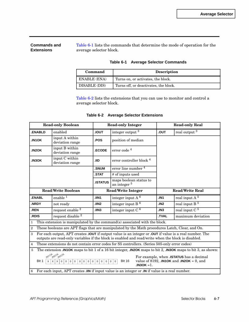
Average Selector
Selector Blocks 6-7APT Programming Reference (Graphics/Math)
Table 6-1 lists the commands that determine the mode of operation for theaverage selector block.
Table 6-1 Average Selector Commands
Command Description
ENABLE (ENA) Turns on, or activates, the block.
DISABLE (DIS) Turns off, or deactivates, the block.
Table 6-2 lists the extensions that you can use to monitor and control aaverage selector block.
Table 6-2 Average Selector Extensions
Read-only Boolean Read-only Integer Read-only Real
.ENABLD enabled .IOUT integer output 3 .OUT real output 3
.IN1OKinput A withindeviation range
.POS position of median
.IN2OKinput B withindeviation range
.ECODE error code 4
.IN3OKinput C withindeviation range
.IID error controller block 4
.SNUM error line number 4
.STAT # of inputs used
.ISTATUSmaps boolean status toan integer 5
Read/Write Boolean Read/Write Integer Read/Write Real
.ENABL enable 1 .IIN1 integer input A 6 .IN1 real input A 5
.NRDY not ready .IIN2 integer input B 6 .IN2 real input B 5
.REN request enable 2 .IIN3 integer input C 6 .IN3 real input C 5
.RDIS request disable 2 .TVAL maximum deviation
1 This extension is manipulated by the command(s) associated with the block.
2 These booleans are APT flags that are manipulated by the Math procedures Latch, Clear, and On.
3 For each output, APT creates .IOUT if output value is an integer or .OUT if value is a real number. Theoutputs are read-only variables if the block is enabled and read/write when the block is disabled.
4 These extensions do not contain error codes for S5 controllers. (Series 505-only error codes)
5 The extension .IN1OK maps to bit 1 of a 16 bit integer, .IN2OK maps to bit 2, .IN3OK maps to bit 3, as shown:
Bit 1 X X X 0 0 0 0 0 0 0 0 0 0 0 0 0 Bit 16For example, when .ISTATUS has a decimalvalue of 8192, .IN1OK and .IN2OK = 0, and.IN3OK =1.
6 For each input, APT creates .IIN if input value is an integer or .IN if value is a real number.
Commands andExtensions

High Selector
Selector Blocks6-8 APT Programming Reference (Graphics/Math)
6.3 High Selector
The high selector block selects the highest of up to four enabled inputs andmoves it to the output.
The block automatically enables only those inputs for which you eitherenter names or draw graphic connections. Inputs that are neither namednor graphically connected are automatically disabled. You can also enablean input by setting the corresponding .SW extension to 1, or you can disableit by setting the .SW extension to 0.
High selector blocks are available for Series 505 and S5 controllers. Theyare not supported for the 560/560T controllers.
When you define a high selector CFB with the form shown in Figure 6-4,you have the following options:
You can use the default names that appear in the form. The defaultextensions must correspond to the correct slot; i.e., .IN1 or .IIN1 must beinput A, etc.
You can add new names: declared variables or dot extensions fromother blocks.
You can leave fields blank.
Overview
Availability
BlockConfiguration
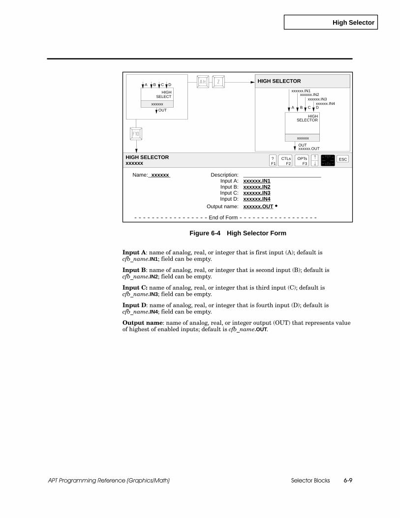
High Selector
Selector Blocks 6-9APT Programming Reference (Graphics/Math)
Name: xxxxxx Description:Input A: xxxxxx.IN1Input B: xxxxxx.IN2Input C: xxxxxx.IN3Input D: xxxxxx.IN4
Output name: xxxxxx.OUT S
-- -- -- -- -- -- -- -- -- -- -- -- -- -- -- -- -- End of Form -- -- -- -- -- -- -- -- -- -- -- -- -- -- -- -- -- --
HIGH SELECTOR
HIGH SELECTORxxxxxx
?F1
ESCCTLsF2
OPTsF3
A
xxxxxx
xxxxxx
HIGH
HIGH
B C
OUTA B C
OUT
SELECTxxxxxx.IN1
xxxxxx.IN2xxxxxx.IN3
xxxxxx.OUT
SELECTOR
D
Dxxxxxx.IN4
Figure 6-4 High Selector Form
Input A: name of analog, real, or integer that is first input (A); default iscfb_name.IN1; field can be empty.
Input B: name of analog, real, or integer that is second input (B); default iscfb_name.IN2; field can be empty.
Input C: name of analog, real, or integer that is third input (C); default iscfb_name.IN3; field can be empty.
Input D: name of analog, real, or integer that is fourth input (D); default iscfb_name.IN4; field can be empty.
Output name: name of analog, real, or integer output (OUT) that represents valueof highest of enabled inputs; default is cfb_name.OUT.

High Selector
Selector Blocks6-10 APT Programming Reference (Graphics/Math)
High Selector (continued)
Table 6-3 lists the commands that determine the mode of operation for thehigh selector block.
Table 6-3 High Selector Commands
Command Description
ENABLE (ENA) Turns on, or activates, the block.
DISABLE (DIS) Turns off, or deactivates, the block.
Table 6-4 lists the extensions that you can use to monitor and control a highselector block.
Table 6-4 High Selector Extensions
Read-only Boolean Read-only Integer Read-only Real
.ENABLD enabled .IOUT integer output 3 .OUT real output 3
.POS current high input
.ECODE error code 4
.IID error controller block 4
.SNUM error line number 4
Read/Write Boolean Read/Write Integer Read/Write Real
.ENABL enable 1 .IIN1 integer input A 5 .IN1 real input A 5
.NRDY not ready .IIN2 integer input B 5 .IN2 real input B 5
.REN request enable 2 .IIN3 integer input C 5 .IN3 real input C 5
.RDIS request disable 2 .IIN4 integer input D 5 .IN4 real input D 5
.SW1 input A enable
.SW2 input B enable
.SW3 input C enable
.SW4 input D enable
1 This extension is manipulated by the command(s) associated with the block.
2 These booleans are APT flags that are manipulated by the Math procedures Latch, Clear, and On.
3 For each output, APT creates .IOUT if output value is an integer or analog or .OUT if value is a real number.The outputs are read-only variables if the block is enabled and read/write when the block is disabled.
4 These extensions do not contain error codes for S5 controllers. (Series 505-only error codes)
5 For each input, APT creates .IIN if input value is an integer or .IN if value is a real number.
Commands andExtensions

Inswitch Selector
Selector Blocks 6-11APT Programming Reference (Graphics/Math)
6.4 Inswitch Selector
The inswitch selector block allows you to select from among four inputs.
You select the input by setting the value of the .POS (position) extension.You can set the value of the .POS extension either directly or by using theSWITCH command in an SFC step.
The value of .POS must be 1, 2, 3, or 4; if you use SWITCH, this correspondsto settings A, B, C, or D.
For example, both of these instructions produce the same result, namely,they send the input signal C to the output.
block_name .POS := 3;SWITCH block_name C;
Inswitch selector blocks are available for Series 505 and S5 controllers.They are not supported for the 560/560T controllers.
Overview
Availability

Inswitch Selector
Selector Blocks6-12 APT Programming Reference (Graphics/Math)
Inswitch Selector (continued)
When you define an inswitch selector CFB with the form in Figure 6-5, youhave the following options:
You can use the default names that appear in the form. The defaultextensions must correspond to the correct slot; i.e., .IN1 or .IIN1 must beinput A, etc.
You can add new names: declared variables or dot extensions fromother blocks.
You can leave fields blank.
Name: xxxxxx Description:Input A: xxxxxx.IN1Input B: xxxxxx.IN2Input C: xxxxxx.IN3Input D: xxxxxx.IN4
Output name: xxxxxx.OUT S
-- -- -- -- -- -- -- -- -- -- -- -- -- -- -- -- -- End of Form -- -- -- -- -- -- -- -- -- -- -- -- -- -- -- -- -- --
INSWITCH SELECTOR
INSWITCH SELECTORxxxxxx
?F1
ESCCTLsF2
OPTsF3
A
xxxxxx
xxxxxx
INSWITCH
B C
OUTA B C
OUT
xxxxxx.IN1xxxxxx.IN2
xxxxxx.IN3
xxxxxx.OUT
SELECT
D
Dxxxxxx.IN4
INSWITCHSELECT
Figure 6-5 Inswitch Selector Form
Input A: name of analog, real, or integer that is first input (A); default iscfb_name.IN1; field can be empty.
Input B: name of analog, real, or integer that is second input (B); default iscfb_name.IN2; field can be empty.
Input C: name of analog, real, or integer that is third input (C); default iscfb_name.IN3; field can be empty.
Input D: name of analog, real, or integer that is fourth input (D); default iscfb_name.IN4; field can be empty.
Output name: name of analog, real, or integer output (OUT) that represents valueof selected input; default is cfb_name.OUT.
BlockConfiguration
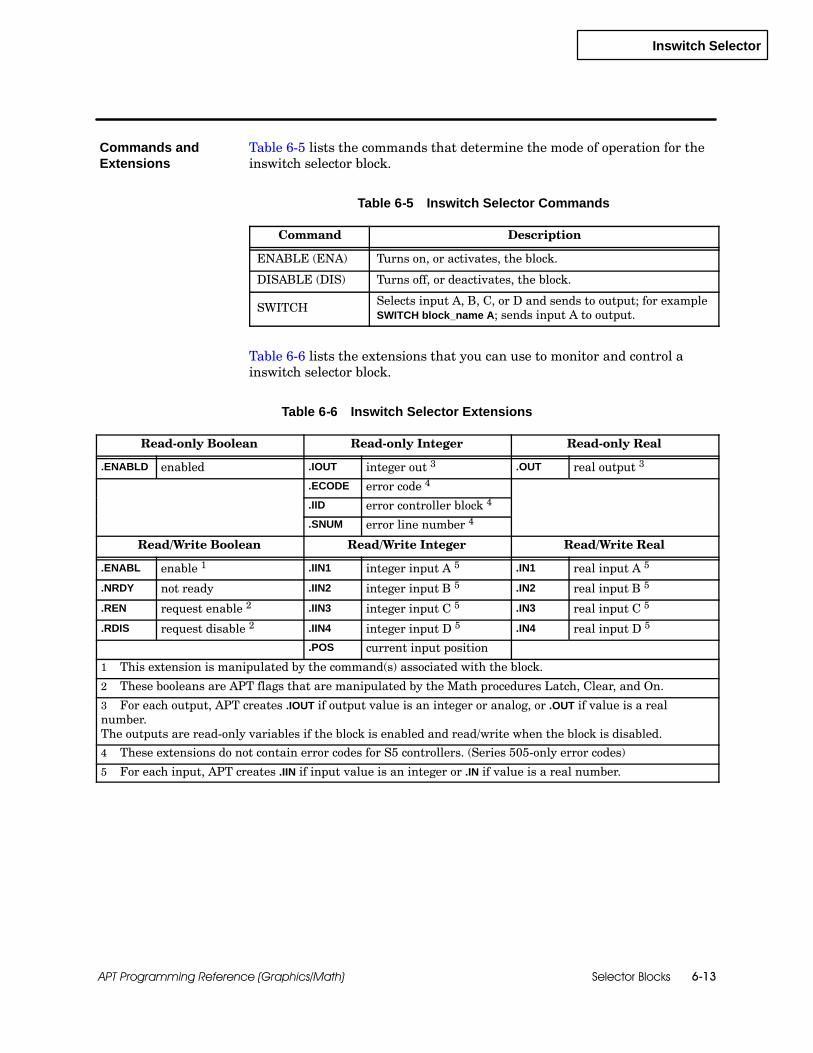
Inswitch Selector
Selector Blocks 6-13APT Programming Reference (Graphics/Math)
Table 6-5 lists the commands that determine the mode of operation for theinswitch selector block.
Table 6-5 Inswitch Selector Commands
Command Description
ENABLE (ENA) Turns on, or activates, the block.
DISABLE (DIS) Turns off, or deactivates, the block.
SWITCH Selects input A, B, C, or D and sends to output; for exampleSWITCH block_name A; sends input A to output.
Table 6-6 lists the extensions that you can use to monitor and control ainswitch selector block.
Table 6-6 Inswitch Selector Extensions
Read-only Boolean Read-only Integer Read-only Real
.ENABLD enabled .IOUT integer out 3 .OUT real output 3
.ECODE error code 4
.IID error controller block 4
.SNUM error line number 4
Read/Write Boolean Read/Write Integer Read/Write Real
.ENABL enable 1 .IIN1 integer input A 5 .IN1 real input A 5
.NRDY not ready .IIN2 integer input B 5 .IN2 real input B 5
.REN request enable 2 .IIN3 integer input C 5 .IN3 real input C 5
.RDIS request disable 2 .IIN4 integer input D 5 .IN4 real input D 5
.POS current input position
1 This extension is manipulated by the command(s) associated with the block.
2 These booleans are APT flags that are manipulated by the Math procedures Latch, Clear, and On.
3 For each output, APT creates .IOUT if output value is an integer or analog, or .OUT if value is a realnumber.The outputs are read-only variables if the block is enabled and read/write when the block is disabled.
4 These extensions do not contain error codes for S5 controllers. (Series 505-only error codes)
5 For each input, APT creates .IIN if input value is an integer or .IN if value is a real number.
Commands andExtensions

Low Selector
Selector Blocks6-14 APT Programming Reference (Graphics/Math)
6.5 Low Selector
The low selector block selects the lowest of up to four enabled inputs andmoves it to the output.
The block automatically enables only those inputs for which you eitherenter names or draw graphic connections. Inputs that are neither namednor graphically connected are automatically disabled. You can also enablean input by setting the corresponding .SW extension to 1, or you can disableit by setting the .SW extension to 0.
Low selector blocks are available for Series 505 and S5 controllers. They arenot supported for the 560/560T controllers.
When you define a low selector CFB with the form that is shown inFigure 6-6, you have the following options.
You can use the default names that appear in the form. The defaultextensions must correspond to the correct slot; i.e., .IN1 or .IIN1 must beinput A, etc.
You can add new names: declared variables or dot extensions fromother blocks.
You can leave fields blank.
Overview
Availability
BlockConfiguration
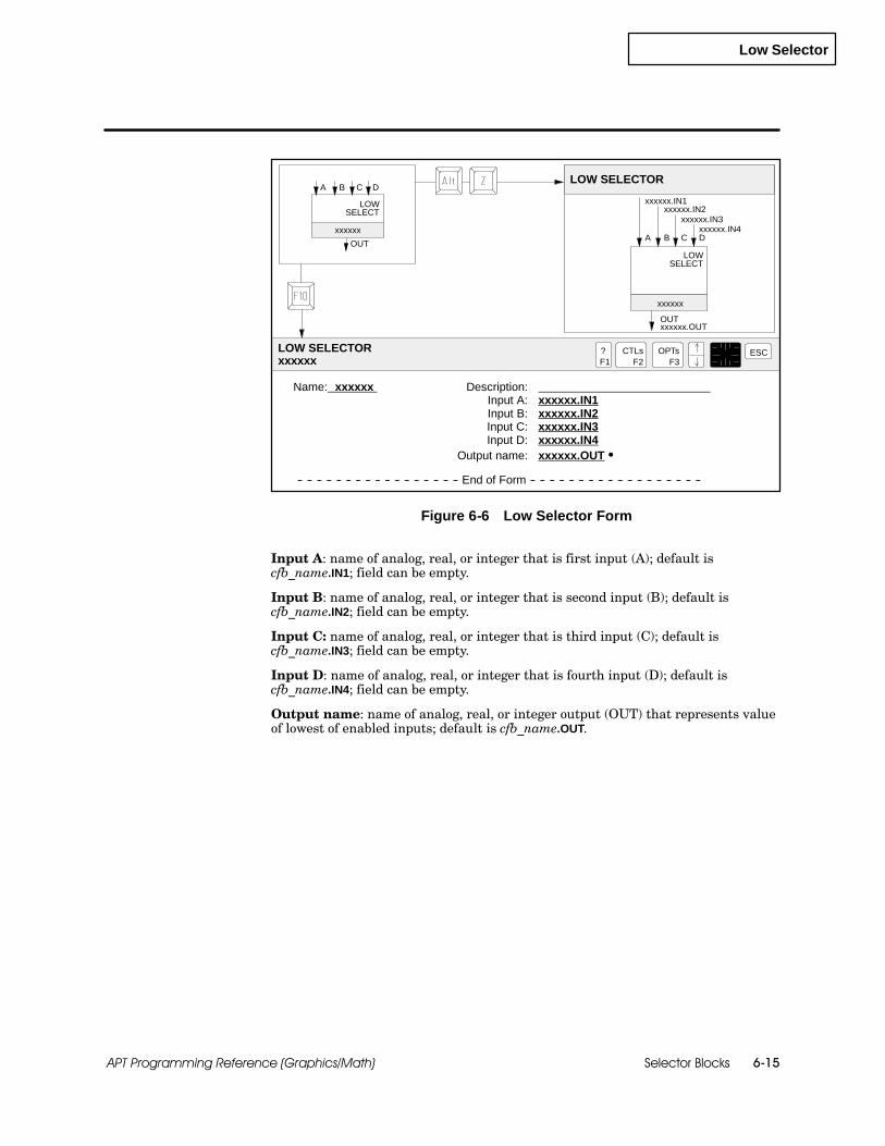
Low Selector
Selector Blocks 6-15APT Programming Reference (Graphics/Math)
Name: xxxxxx Description:Input A: xxxxxx.IN1Input B: xxxxxx.IN2Input C: xxxxxx.IN3Input D: xxxxxx.IN4
Output name: xxxxxx.OUT S
-- -- -- -- -- -- -- -- -- -- -- -- -- -- -- -- -- End of Form -- -- -- -- -- -- -- -- -- -- -- -- -- -- -- -- -- --
LOW SELECTOR
LOW SELECTORxxxxxx
?F1
ESCCTLsF2
OPTsF3
A
xxxxxx
xxxxxx
LOW
LOW
B C
OUTA B C
OUT
xxxxxx.IN1xxxxxx.IN2
xxxxxx.IN3
xxxxxx.OUT
SELECT
D
Dxxxxxx.IN4
SELECT
Figure 6-6 Low Selector Form
Input A: name of analog, real, or integer that is first input (A); default iscfb_name.IN1; field can be empty.
Input B: name of analog, real, or integer that is second input (B); default iscfb_name.IN2; field can be empty.
Input C: name of analog, real, or integer that is third input (C); default iscfb_name.IN3; field can be empty.
Input D: name of analog, real, or integer that is fourth input (D); default iscfb_name.IN4; field can be empty.
Output name: name of analog, real, or integer output (OUT) that represents valueof lowest of enabled inputs; default is cfb_name.OUT.
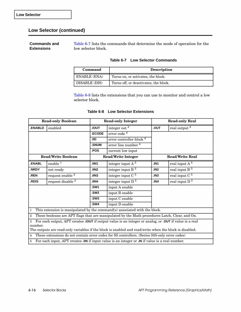
Low Selector
Selector Blocks6-16 APT Programming Reference (Graphics/Math)
Low Selector (continued)
Table 6-7 lists the commands that determine the mode of operation for thelow selector block.
Table 6-7 Low Selector Commands
Command Description
ENABLE (ENA) Turns on, or activates, the block.
DISABLE (DIS) Turns off, or deactivates, the block.
Table 6-8 lists the extensions that you can use to monitor and control a lowselector block.
Table 6-8 Low Selector Extensions
Read-only Boolean Read-only Integer Read-only Real
.ENABLD enabled .IOUT integer out 3 .OUT real output 3
.ECODE error code 4
.IID error controller block 4
.SNUM error line number 4
.POS current low input
Read/Write Boolean Read/Write Integer Read/Write Real
.ENABL enable 1 .IIN1 integer input A 5 .IN1 real input A 5
.NRDY not ready .IIN2 integer input B 5 .IN2 real input B 5
.REN request enable 2 .IIN3 integer input C 5 .IN3 real input C 5
.RDIS request disable 2 .IIN4 integer input D 5 .IN4 real input D 5
.SW1 input A enable
.SW2 input B enable
.SW3 input C enable
.SW4 input D enable
1 This extension is manipulated by the command(s) associated with the block.
2 These booleans are APT flags that are manipulated by the Math procedures Latch, Clear, and On.
3 For each output, APT creates .IOUT if output value is an integer or analog, or .OUT if value is a realnumber.The outputs are read-only variables if the block is enabled and read/write when the block is disabled.
4 These extensions do not contain error codes for S5 controllers. (Series 505-only error codes)
5 For each input, APT creates .IIN if input value is an integer or .IN if value is a real number.
Commands andExtensions

Median Selector
Selector Blocks 6-17APT Programming Reference (Graphics/Math)
6.6 Median Selector
The median selector block selects the numerical median of three inputs.
Median selector blocks are available for Series 505 and S5 controllers. Theyare not supported for the 560/560T controllers.
When you define a median selector CFB with the form in Figure 6-7, youhave the following options:
You can use the default names that appear in the form. The defaultextensions must correspond to the correct slot; i.e., .IN1 or .IIN1 must beinput A, etc.
You can add new names: declared variables or dot extensions fromother blocks.
Name: xxxxxx Description:Input A: xxxxxx.IN1Input B: xxxxxx.IN2Input C: xxxxxx.IN3
Output name: xxxxxx.OUT S
-- -- -- -- -- -- -- -- -- -- -- -- -- -- -- -- -- End of Form -- -- -- -- -- -- -- -- -- -- -- -- -- -- -- -- -- --
MEDIAN SELECTOR
MEDIAN SELECTORxxxxxx
?F1
ESCCTLsF2
OPTsF3
A
xxxxxx
xxxxxx
MEDIAN
MEDIAN
B C
OUTA B C
OUT
SELECTxxxxxx.IN1
xxxxxx.IN2xxxxxx.IN3
xxxxxx.OUT
SELECT
Figure 6-7 Median Selector Form
Input A: name of analog, real, or integer that is first input (A); default iscfb_name.IN1.
Input B: name of analog, real, or integer that is second input (B); default iscfb_name.IN2.
Input C: name of analog, real, or integer that is third input (C); default iscfb_name.IN3.
Output name: name of analog, real, or integer output (OUT) that represents valueof median of enabled inputs; default is cfb_name.OUT.
Overview
Availability
BlockConfiguration

Median Selector
Selector Blocks6-18 APT Programming Reference (Graphics/Math)
Median Selector (continued)
Table 6-9 lists the commands that determine the mode of operation for themedian selector block.
Table 6-9 Median Selector Commands
Command Description
ENABLE (ENA) Turns on, or activates, the block.
DISABLE (DIS) Turns off, or deactivates, the block.
Table 6-10 lists the extensions that you can use to monitor and control amedian selector block.
Table 6-10 Median Selector Extensions
Read-only Boolean Read-only Integer Read-only Real
.ENABLD enabled .IOUT integer out 3 .OUT real output 3
.ECODE error code 4
.IID error controller block 4
.SNUM error line number 4
.POS position of median
Read/Write Boolean Read/Write Integer Read/Write Real
.ENABL enable 1 .IIN1 integer input A 5 .IN1 real input A 5
.NRDY not ready .IIN2 integer input B 5 .IN2 real input B 5
.REN request enable 2 .IIN3 integer input C 5 .IN3 real input C 5
.RDIS request disable 3
1 This extension is manipulated by the command(s) associated with the block.
2 These booleans are APT flags that are manipulated by the Math procedures Latch, Clear, and On.
3 For each output, APT creates .IOUT if output value is an integer or analog, or .OUT if value is a realnumber.The outputs are read-only variables if the block is enabled and read/write when the block is disabled.
4 These extensions do not contain error codes for S5 controllers. (Series 505-only error codes)
5 For each input, APT creates .IIN if input value is an integer or .IN if value is a real number.
Commands andExtensions
Outswitch Selector
Selector Blocks 6-19APT Programming Reference (Graphics/Math)
6.7 Outswitch Selector
The outswitch selector block allows you to send an input signal to any one offour outputs. You select the output by setting the value of the .POSextension. You can set the value of the .POS extension directly or you canuse the SWITCH command in an SFC step.
For example, both of these instructions produce the same result, namely,they send the input signal to output C.
block_name .POS := 3;SWITCH block_name C;
Outswitch selector blocks are available for Series 505 and S5 controllers.They are not supported for the 560/560T controllers.
When you define an outswitch selector CFB with the form in Figure 6-8, youhave the following options:
You can use the default names that appear in the form. The defaultextensions must correspond to the correct slot; i.e., .OUT1 or .IOUT1must be output A, etc.
You can add new names: declared variables or dot extensions fromother blocks.
You can leave fields blank.
APT, also allows you to write directly to the unselected output; e.g., if theswitch is set to A, you can write to the B, C, and D .PVx extensions.
Overview
Availability
BlockConfiguration

Outswitch Selector
Selector Blocks6-20 APT Programming Reference (Graphics/Math)
Outswitch Selector (continued)
Name: xxxxxx Description:Input name: xxxxxx.IN
Output A: xxxxxx.OUT1 SOutput B: xxxxxx.OUT2 SOutput C: xxxxxx.OUT3 SOutput D: xxxxxx.OUT4 S
-- -- -- -- -- -- -- -- -- -- -- -- -- -- -- -- -- End of Form -- -- -- -- -- -- -- -- -- -- -- -- -- -- -- -- -- --
OUTSWITCH SELECTOR
OUTSWITCH SELECTORxxxxxx
?F1
ESCCTLsF2
OPTsF3
A
xxxxxx OUTSWITCH
B C
IN
A B C
IN
xxxxxx.OUT1xxxxxx.OUT2
xxxxxx.OUT3
xxxxxx.IN
SELECTD
Dxxxxxx.OUT4
xxxxxx
OUTSWITCHSELECT
Figure 6-8 Outswitch Selector Form
Input name (IN): name of analog, real, or integer input; default is cfb_name.IN.
Output A (A): name of analog, real, or integer that is first output; default iscfb_name.OUT1; field can be empty.
Output B (B): name of analog, real, or integer that is second output; default iscfb_name.OUT2; field can be empty.
Output C (C): name of analog, real, or integer that is third output; default iscfb_name.OUT3; field can be empty.
Output D (D): name of analog, real, or integer that is fourth output; default iscfb_name.OUT4; field can be empty.

Outswitch Selector
Selector Blocks 6-21APT Programming Reference (Graphics/Math)
Table 6-11 lists the commands that determine the mode of operation for theoutswitch selector block.
Table 6-11 Outswitch Selector Commands
Command Description
ENABLE (ENA) Turns on, or activates, the block.
DISABLE (DIS) Turns off, or deactivates, the block.
SWITCH Selects input A, B, C, or D and sends to output; for exampleSWITCH block_name A; sends input to output A.
Table 6-12 lists the extensions that you can use to monitor and control aoutswitch selector block.
Table 6-12 Outswitch Selector Extensions
Read-only Boolean Read-only Integer Read-only Real
.ENABLD enabled .IOUT1 integer out A 3 .OUT1 real output A 3
.IOUT2 integer out B 3 .OUT2 real output B 3
.IOUT3 integer out C 3 .OUT3 real output C 3
.IOUT4 integer out D 3 .OUT4 real output D 3
.ECODE error code 4
.IID error controller block 4
.SNUM error line number 4
Read/Write Boolean Read/Write Integer Read/Write Real
.ENABL enable 1 .IIN integer input A 5 .IN real input 5
.NRDY not ready .POS current output position .PV1 alternate out A
.REN request enable 2 .PV2 alternate out B
.RDIS request disable 2 .PV3 alternate out C
.PV4 alternate out D
1 This extension is manipulated by the command(s) associated with the block.
2 These booleans are APT flags that are manipulated by the Math procedures Latch, Clear, and On.
3 For each output, APT creates .IOUT if output value is an integer or analog, or .OUT if value is a realnumber.The outputs are read-only variables if the block is enabled and read/write when the block is disabled.
4 These extensions do not contain error codes for S5 controllers. (Series 505-only error codes)
5 For each input, APT creates .IIN if input value is an integer or .IN if value is a real number.
Commands andExtensions
Threshold Selector
Selector Blocks6-22 APT Programming Reference (Graphics/Math)
6.8 Threshold Selector
The threshold selector block monitors a variable to determine whether ornot its value falls below or rises above a specified limit. The initial value ofthe limit is taken from the form definition but can be changed from theprogram.
You can select either a high threshold or a low threshold:
If you select a high threshold, a boolean output becomes true if theinput value is greater than or equal the limit value.
If you select a low threshold, a boolean output becomes true if the inputvalue is less than or equal the limit value.
Threshold selector blocks are available for Series 505 and S5 controllers.They are not supported for the 560/560T controllers.
Overview
Availability

Threshold Selector
Selector Blocks 6-23APT Programming Reference (Graphics/Math)
When you define a threshold selector CFB with the form in Figure 6-9, youhave the following options:
You can use the default names that appear in the form.
You can add new names: declared variables or dot extensions fromother blocks.
Name: xxxxxx Description:Input name: xxxxxx.IN
Output name: xxxxxx.DOUT SThreshold: HIGH LOW
Threshold value:
-- -- -- -- -- -- -- -- -- -- -- -- -- -- -- -- -- End of Form -- -- -- -- -- -- -- -- -- -- -- -- -- -- -- -- -- --
OUT
THRESHOLD SELECTOR
xxxxxx.DOUT
xxxxxx.ININ
THRESHOLD SELECTORxxxxxx
?F1
ESCCTLsF2
OPTsF3
xxxxxx
xxxxxxTHRESHOLD
THRESHLD
OUT
A
SELECT
SELECTOR
Figure 6-9 Threshold Selector Form
Input name: name of analog, real or integer input (A); default is cfb_name.IN.
Output name: name of digital output or boolean variable that is output (OUT);default is cfb_name.DOUT.
Threshold: HIGH or LOW; the default is HIGH.
Threshold value: integer or real value of limit; value must be same type (integeror real) as input.
BlockConfiguration

Threshold Selector
Selector Blocks6-24 APT Programming Reference (Graphics/Math)
Threshold Selector (continued)
Table 6-13 lists the commands that determine the mode of operation for thethreshold selector block.
Table 6-13 Threshold Selector Commands
Command Description
ENABLE (ENA) Turns on, or activates, the block.
DISABLE (DIS) Turns off, or deactivates, the block.
Table 6-14 lists the extensions that you can use to monitor and control athreshold selector block.
Table 6-14 Threshold Selector Extensions
Read-only Boolean Read-only Integer Read-only Real
.ENABLD enabled .SNUM error line number 4
.DOUT boolean output 1 .ECODE error code 4
.IID error controller block 4
Read/Write Boolean Read/Write Integer Read/Write Real
.ENABL enable 2 .IIN integer input A 5 .IN input 5
.NRDY not ready .LIMIT limit if input is integer 5 .LIMIT limit if input is real 5
.REN request enable 3
.RDIS request disable 3
1 The output is a read-only variable when the block is enabled and read/write when the block is disabled.
2 This extension is manipulated by the command(s) associated with the block.
3 These booleans are APT flags that are manipulated by the Math procedures Latch, Clear, and On.
4 These extensions do not contain error codes for S5 controllers. (Series 505-only error codes)
5 If the input is an integer, APT creates .IIN; and .LIMIT is an integer. If the input is a real value, APT creates.IN and .LIMIT is a real value.
Commands andExtensions
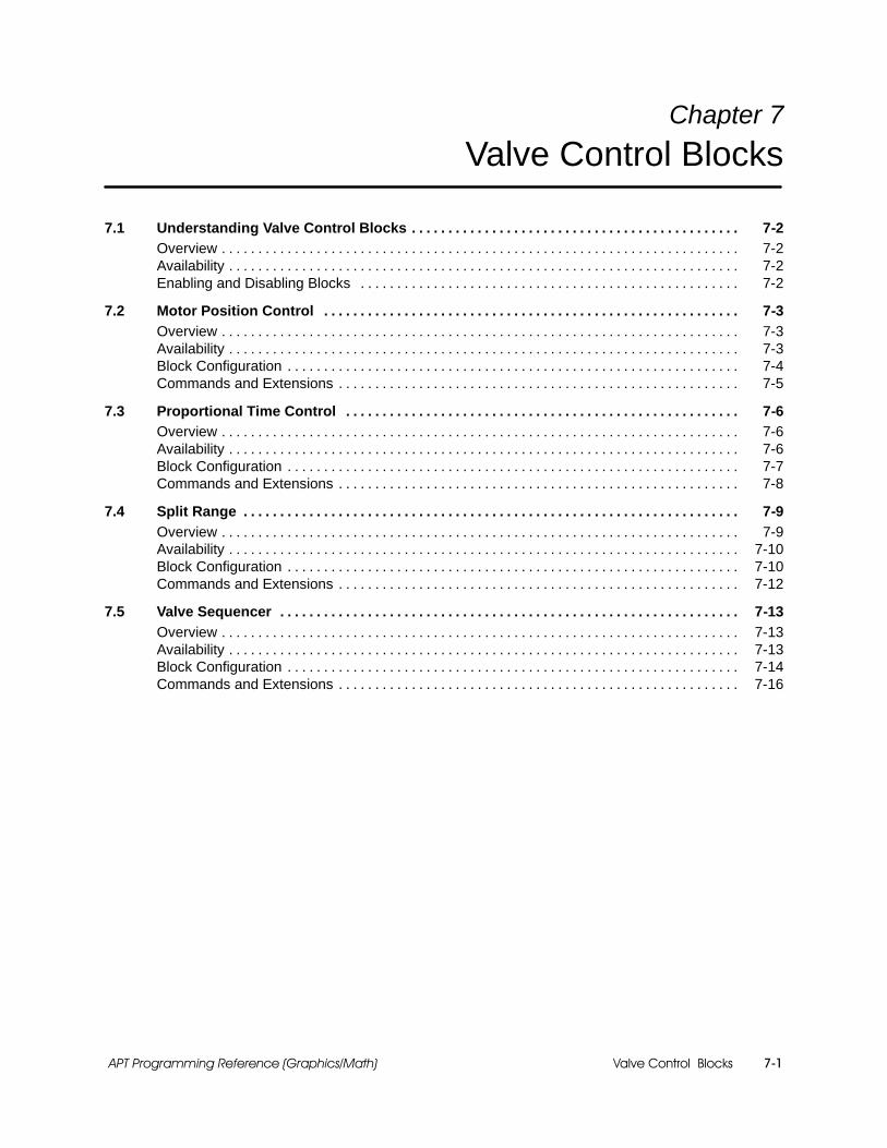
Valve Control Blocks 7-1APT Programming Reference (Graphics/Math)
Chapter 7
Valve Control Blocks
7.1 Understanding Valve Control Blocks 7-2. . . . . . . . . . . . . . . . . . . . . . . . . . . . . . . . . . . . . . . . . . . . .Overview 7-2. . . . . . . . . . . . . . . . . . . . . . . . . . . . . . . . . . . . . . . . . . . . . . . . . . . . . . . . . . . . . . . . . . . . . . .Availability 7-2. . . . . . . . . . . . . . . . . . . . . . . . . . . . . . . . . . . . . . . . . . . . . . . . . . . . . . . . . . . . . . . . . . . . . .Enabling and Disabling Blocks 7-2. . . . . . . . . . . . . . . . . . . . . . . . . . . . . . . . . . . . . . . . . . . . . . . . . . . .
7.2 Motor Position Control 7-3. . . . . . . . . . . . . . . . . . . . . . . . . . . . . . . . . . . . . . . . . . . . . . . . . . . . . . . . .Overview 7-3. . . . . . . . . . . . . . . . . . . . . . . . . . . . . . . . . . . . . . . . . . . . . . . . . . . . . . . . . . . . . . . . . . . . . . .Availability 7-3. . . . . . . . . . . . . . . . . . . . . . . . . . . . . . . . . . . . . . . . . . . . . . . . . . . . . . . . . . . . . . . . . . . . . .Block Configuration 7-4. . . . . . . . . . . . . . . . . . . . . . . . . . . . . . . . . . . . . . . . . . . . . . . . . . . . . . . . . . . . . .Commands and Extensions 7-5. . . . . . . . . . . . . . . . . . . . . . . . . . . . . . . . . . . . . . . . . . . . . . . . . . . . . . .
7.3 Proportional Time Control 7-6. . . . . . . . . . . . . . . . . . . . . . . . . . . . . . . . . . . . . . . . . . . . . . . . . . . . . .Overview 7-6. . . . . . . . . . . . . . . . . . . . . . . . . . . . . . . . . . . . . . . . . . . . . . . . . . . . . . . . . . . . . . . . . . . . . . .Availability 7-6. . . . . . . . . . . . . . . . . . . . . . . . . . . . . . . . . . . . . . . . . . . . . . . . . . . . . . . . . . . . . . . . . . . . . .Block Configuration 7-7. . . . . . . . . . . . . . . . . . . . . . . . . . . . . . . . . . . . . . . . . . . . . . . . . . . . . . . . . . . . . .Commands and Extensions 7-8. . . . . . . . . . . . . . . . . . . . . . . . . . . . . . . . . . . . . . . . . . . . . . . . . . . . . . .
7.4 Split Range 7-9. . . . . . . . . . . . . . . . . . . . . . . . . . . . . . . . . . . . . . . . . . . . . . . . . . . . . . . . . . . . . . . . . . . .Overview 7-9. . . . . . . . . . . . . . . . . . . . . . . . . . . . . . . . . . . . . . . . . . . . . . . . . . . . . . . . . . . . . . . . . . . . . . .Availability 7-10. . . . . . . . . . . . . . . . . . . . . . . . . . . . . . . . . . . . . . . . . . . . . . . . . . . . . . . . . . . . . . . . . . . . . .Block Configuration 7-10. . . . . . . . . . . . . . . . . . . . . . . . . . . . . . . . . . . . . . . . . . . . . . . . . . . . . . . . . . . . . .Commands and Extensions 7-12. . . . . . . . . . . . . . . . . . . . . . . . . . . . . . . . . . . . . . . . . . . . . . . . . . . . . . .
7.5 Valve Sequencer 7-13. . . . . . . . . . . . . . . . . . . . . . . . . . . . . . . . . . . . . . . . . . . . . . . . . . . . . . . . . . . . . . .Overview 7-13. . . . . . . . . . . . . . . . . . . . . . . . . . . . . . . . . . . . . . . . . . . . . . . . . . . . . . . . . . . . . . . . . . . . . . .Availability 7-13. . . . . . . . . . . . . . . . . . . . . . . . . . . . . . . . . . . . . . . . . . . . . . . . . . . . . . . . . . . . . . . . . . . . . .Block Configuration 7-14. . . . . . . . . . . . . . . . . . . . . . . . . . . . . . . . . . . . . . . . . . . . . . . . . . . . . . . . . . . . . .Commands and Extensions 7-16. . . . . . . . . . . . . . . . . . . . . . . . . . . . . . . . . . . . . . . . . . . . . . . . . . . . . . .

Valve Control Blocks7-2 APT Programming Reference (Graphics/Math)
7.1 Understanding Valve Control Blocks
The APT valve blocks provide additional valve control:
The motor position control block allows you to set a motor driven valvein an intermediate position, neither fully opened or fully closed.
The proportional time control block allows you to make a discretedevice perform like a continuous device.
The split range block allows you to use analog outputs for valve control.
The valve sequencer allows you to control two valves with one output.
All valve blocks are available for Series 505 and S5 controllers. They are notsupported for the 560/560T controllers.
All valve CFBs must be activated with the ENABLE command or with anassignment statement that sets the .ENABL extension to true. SeeFigure 7-1. Valve blocks can also be enabled from an assignment statementin a math CFB.
cfb_name.ENABL := true;Enable cfb_name;
S3 ENABLE cfb_name;A
xxxxxx
MATH
B C D
E F G H
Figure 7-1 Enabling a Valve CFB
To deactivate the block, use the DISABLE command with the block name, orset the .ENABL extension to false.
All valve blocks have a boolean extension (.NRDY) that you can use tointerlock the execution of the block to some external conditions.
If you set the .NRDY extension to true, the block is forced to the disabledstate.
To return the block to the enabled state you must not only set the.NRDY extension to false, but you must also re-enable the block with anenable command or an assignment statement.
Overview
Availability
Enabling andDisabling Blocks

Motor Position Control
Valve Control Blocks 7-3APT Programming Reference (Graphics/Math)
7.2 Motor Position Control
The motor position control block is used to drive a motor-driven valve to anintermediate position between 0 and 100%. The motor-driven valve is adevice (VMD) that you define in the Device Definition Table.
The input to the block is a feedback signal that indicates the position of thevalve. The setpoint should be a real value between 0.0 and 1.0. Thealgorithm compares the input to the setpoint.
If the difference between the input and the setpoint is outside therange specified by the dead zone, the signals that open and close thevalve are manipulated.
If the difference between the input and the setpoint is within the deadzone, no control action is taken.
The dead zone is entered in the form as a percentage (0 to 100). If you wantto change the dead zone from the program, write a value that is between 0.0and 1.0 to the .DBAND (dead band) extension.
The motor position control block expects the valve to be in a locked state.(See the “Devices” chapter in the APT Programming Reference (Tables)Manual for information about locking a motor-driven valve.) If the block isenabled and the valve is not locked, the block does not execute until thevalve is locked. The block does not check any other status bits that areassociated with the valve. Every time the block is enabled, the value of theinput is copied to the setpoint, effecting a “bumpless” transfer.
The motor position control block is supported for Series 505 and S5controllers, but not the 560/560T controllers.
Overview
Availability

Motor Position Control
Valve Control Blocks7-4 APT Programming Reference (Graphics/Math)
Motor Position Control (continued)
When you define a motor position control CFB with the form in Figure 7-2,you have the following options:
You can use the default names that appear in the form.
You can add new names: declared variables or dot extensions fromother blocks.
MOTOR POSITION CONTROL (ABSOLUTE)
Name: xxxxxx Description:Position feedback: xxxxxx.IN S
Setpoint: xxxxxx.SPDevice:
Dead zone (%): 0.1
-- -- -- -- -- -- -- -- -- -- -- -- -- -- -- -- -- End of Form -- -- -- -- -- -- -- -- -- -- -- -- -- -- -- -- -- --
SP
xxxxxx.INPF
MOTOR POSITION CONTROL (ABSOLUTE)xxxxxx
?F1
ESCCTLsF2
OPTsF3
PFSP
xxxxxx
xxxxxx
MTR. POS.CONTROL
xxxxxx.SP MTR. POS.CONTROL
Figure 7-2 Motor Position Control Form
Position feedback: name of analog or real input (PV) that represents positionfeedback of valve as a scaled value between 0 and 1; default is cfb_name.IN.
Setpoint: name of real variable (SP) that represents setpoint (desired position ofvalve) as a scaled value between 0 and 1; default is cfb_name.SP.
Device: name of motor-driven valve (type VMD) that is to be controlled by thisblock; device is configured in Device Definition Table.
Dead zone(%): size of dead zone as a percentage (0 to 100); default is 0.1.
BlockConfiguration
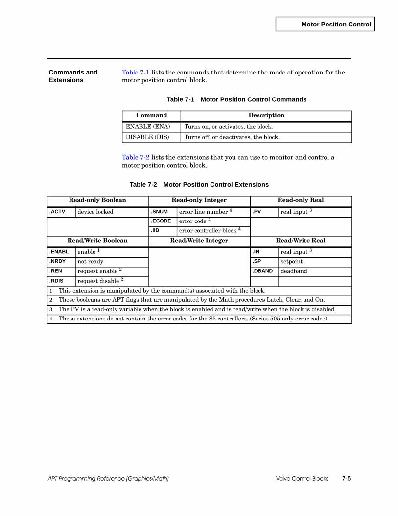
Motor Position Control
Valve Control Blocks 7-5APT Programming Reference (Graphics/Math)
Table 7-1 lists the commands that determine the mode of operation for themotor position control block.
Table 7-1 Motor Position Control Commands
Command Description
ENABLE (ENA) Turns on, or activates, the block.
DISABLE (DIS) Turns off, or deactivates, the block.
Table 7-2 lists the extensions that you can use to monitor and control amotor position control block.
Table 7-2 Motor Position Control Extensions
Read-only Boolean Read-only Integer Read-only Real
.ACTV device locked .SNUM error line number 4 .PV real input 3
.ECODE error code 4
.IID error controller block 4
Read/Write Boolean Read/Write Integer Read/Write Real
.ENABL enable 1 .IN real input 3
.NRDY not ready .SP setpoint
.REN request enable 2 .DBAND deadband
.RDIS request disable 2
1 This extension is manipulated by the command(s) associated with the block.
2 These booleans are APT flags that are manipulated by the Math procedures Latch, Clear, and On.
3 The PV is a read-only variable when the block is enabled and is read/write when the block is disabled.
4 These extensions do not contain the error codes for the S5 controllers. (Series 505-only error codes)
Commands andExtensions
Proportional Time Control
Valve Control Blocks7-6 APT Programming Reference (Graphics/Math)
7.3 Proportional Time Control
The proportional time control block is used to make an on/off device act likea continuous device. This block allows you to set an output to true for aspecified fraction of its duty cycle and to false the rest of the time.
Proportional time control is commonly applied to extruders. For example,you might control the temperature of a zone in an extruder by switching theheater associated with that zone on and off.
By pulsing an output according to the load on the system, the oscillation ofthe controlled variable can be reduced; and the amount of energy added tothe system is more in line with what is needed. For example, a fully loadedsystem has full heating all of the time; a system with no load has heatingnone of the time.
The input to the block specifies the fraction of the time that the controloutput should be true (open or running for devices). The duty cycle specifieshow often the algorithm should re-evaluate the on/off time of the output.For example, if the duty cycle is 10 seconds and the input variable is 0.5, theoutput is true for five seconds and false for five seconds. At the end of eachten-second period, the input is re-evaluated to determine the on/off time forthe output.
Any device except a two-speed or reversible motor can be used with theproportional time control block. See the “Devices” chapter in the APTProgramming Reference (Tables) Manual for information about thesedevices.
The proportional time control block is supported for both Series 505 and S5controllers, but not for the 560/560T controllers.
Overview
Availability

Proportional Time Control
Valve Control Blocks 7-7APT Programming Reference (Graphics/Math)
When you define a proportional time control CFB with the form that isshown in Figure 7-3, you have the following options:
You can use the default names that appear in the form.
You can add new names: declared variables or dot extensions fromother blocks.
xxxxxx
PROPORTIONAL TIME CONTROL
xxxxxx
Name: xxxxxx Description:Input name: xxxxxx.IN
Output name: xxxxxx.DOUT SDuty cycle: 10.0 sec
-- -- -- -- -- -- -- -- -- -- -- -- -- -- -- -- -- End of Form -- -- -- -- -- -- -- -- -- -- -- -- -- -- -- -- -- --
xxxxxx.ININ
PROPORTIONAL TIME CONTROLxxxxxx
?F1
ESCCTLsF2
OPTsF3
IN
PROP.TIME
PROPORTIONALTIME CONTROL
Figure 7-3 Proportional Time Control Form
Input name: name of real input (IN) that represents fraction of duty cycle duringwhich the output is true; value must be between 0.0 and 1.0; default is cfb_name.IN.
Output name: name of output (OUT); name can be boolean or discrete variable orname of device (VSS, VMD, VSD, VSN, VDD, MDS, MDN, MSN, MSS). Thespecified output becomes true for the fraction of the duty cycle specified by input; ithas a value of false for the remainder of the duty cycle; default is cfb_name.DOUT.
Duty cycle: duration of duty cycle, in seconds; value depends on the timercompiled. An initial value 32 seconds generates a fast timer. A fast timer has arange of 0.001 to 32.767 seconds in 0.001 second increments. An initial value > 32seconds generates a slow timer. A slow timer has a range of 0.1 to 3276.7 seconds in0.1 second increments. If you have an S5 controller, APT automatically assigns youthe slow timer.
During operation, the range for the duty cycle dot extension value is limited to therange of the timer generated. Although you can enter a specific duty cycle, theexecution time of the CFB is determined in part by how fast the associated SFPGMfor Series 505 can be executed, or how fast the scan time is for S5 controllers.
BlockConfiguration

Proportional Time Control
Valve Control Blocks7-8 APT Programming Reference (Graphics/Math)
Proportional Time Control (continued)
! WARNINGAPT allows the duty cycle of the proportional time control block to be changedwhile the block is enabled. The new duty cycle value does not take effectimmediately.
Changing the value could cause unpredictable and/or unsafe process operationthat could result in death or serious injury to personnel, and/or equipmentdamage.
Always disable the proportional time control block before changing the value ofthe duty cycle.
Table 7-3 lists the commands that determine the mode of operation for theproportional time control block.
Table 7-3 Proportional Time Control Commands
Command Description
ENABLE (ENA) Turns on, or activates, the block.
DISABLE (DIS) Turns off, or deactivates, the block.
Table 7-4 lists the extensions that you can use to monitor and control aproportional time control block.
Table 7-4 Proportional Time Control Extensions
Read-only Boolean Read-only Integer Read-only Real
.DOUT output to device 1 .SNUM error line number 4
.ECODE error code 4
.IID error controller block 4
Read/Write Boolean Read/Write Integer Read/Write Real
.ENABL enable 2 .INfraction of time output istrue
.NRDY not ready .DUTY duty cycle
.REN request enable 3
.RDIS request disable 3
1 The output is a read-only variable when the block is enabled and read/write when the block is disabled.
2 This extension is manipulated by the command(s) associated with the block.
3 These booleans are APT flags that are manipulated by the Math procedures Latch, Clear, and On.
4 These extensions do not contain the error codes for the S5 controllers. (Series 505-only error codes)
Commands andExtensions

Split Range
Valve Control Blocks 7-9APT Programming Reference (Graphics/Math)
7.4 Split Range
The split range block allows you to split an input signal into two outputsignals. The input must be a real number between 0 and 1.
As the input signal changes from 0.0 to 1.0, the two outputs change. Whenyou define the block, you enter the input range that specifies the input atwhich each output first reaches the 0.0% state.
When the input is 0.0, the first output (A) is 100% (1.0); the secondoutput (B) is 0.0% (0.0). If the reverse scaling option is selected, bothoutputs (A and B) are 0.0% (0.0). See Figure 7-4.
When the input is 1.0, the first output (A) is 0.0% (0.0); the secondoutput (B) is 100.0% (1.0). If the reverse scaling option is selected, bothoutputs (A and B) are 100% (1.0). See Figure 7-4.
Breakpoints can overlap so that at some time both outputs are non-zeroover some range of input values. Also, the breakpoint ranges can be set sothat there is a band of input ranges over which both outputs are 0.0.
If either output is an analog output, the split range block scales the outputsto the appropriate ranges that you specify for the analog outputs. Anextension is also created (.OUT) that contains the scaled real value (0.0 to1.0) of the output.
Input
Output
0.0
1.0
Normal Scaling
1.0
Output
Input
Output
0.0
1.0
Reverse Scaling
1.0
OutputOutput OutputA B A B
0.01.0 0.01.0Input
1.0
Input
1.0
Figure 7-4 Split Range Reverse and Normal Scaling
Overview
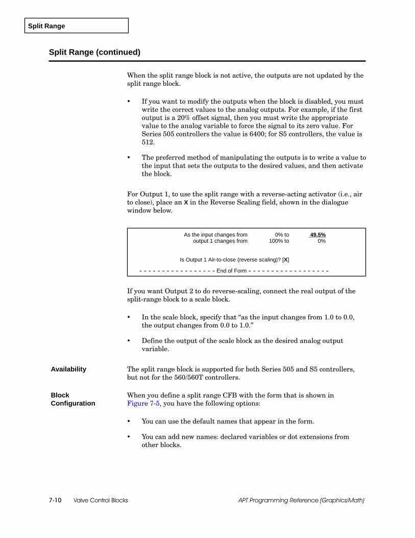
Split Range
Valve Control Blocks7-10 APT Programming Reference (Graphics/Math)
Split Range (continued)
When the split range block is not active, the outputs are not updated by thesplit range block.
If you want to modify the outputs when the block is disabled, you mustwrite the correct values to the analog outputs. For example, if the firstoutput is a 20% offset signal, then you must write the appropriatevalue to the analog variable to force the signal to its zero value. ForSeries 505 controllers the value is 6400; for S5 controllers, the value is512.
The preferred method of manipulating the outputs is to write a value tothe input that sets the outputs to the desired values, and then activatethe block.
For Output 1, to use the split range with a reverse-acting activator (i.e., airto close), place an X in the Reverse Scaling field, shown in the dialoguewindow below.
As the input changes from 0% to 49.5%output 1 changes from 100% to 0%
Is Output 1 Air-to-close (reverse scaling)? [X]
-- -- -- -- -- -- -- -- -- -- -- -- -- -- -- -- -- End of Form -- -- -- -- -- -- -- -- -- -- -- -- -- -- -- -- -- --
If you want Output 2 to do reverse-scaling, connect the real output of thesplit-range block to a scale block.
In the scale block, specify that “as the input changes from 1.0 to 0.0,the output changes from 0.0 to 1.0.”
Define the output of the scale block as the desired analog outputvariable.
The split range block is supported for both Series 505 and S5 controllers,but not for the 560/560T controllers.
When you define a split range CFB with the form that is shown inFigure 7-5, you have the following options:
You can use the default names that appear in the form.
You can add new names: declared variables or dot extensions fromother blocks.
Availability
BlockConfiguration

Split Range
Valve Control Blocks 7-11APT Programming Reference (Graphics/Math)
Name: xxxxxx Description:Input name: xxxxxx.IN
Output 1: xxxxxx.OUT1 SOutput 2: xxxxxx.OUT2 S
As the input changes from 0% to 49.5%output 1 changes from 100% to 0%
As the input changes from 50.5% to 100%output 2 changes from 0% to 100%
Is Output 1 Air-to-close (reverse scaling)? [ ]
-- -- -- -- -- -- -- -- -- -- -- -- -- -- -- -- -- End of Form -- -- -- -- -- -- -- -- -- -- -- -- -- -- -- -- -- --
SPLIT RANGE
xxxxxx.ININ
SPLIT RANGExxxxxx
?F1
ESCCTLsF2
OPTsF3
IN
xxxxxx
xxxxxx
SPLITRANGE
SPLITRANGEOUT1 OUT2
OUT1 OUT2xxxxxx.OUT2
xxxxxx.OUT!
Figure 7-5 Split Range Form
Input name: name of real input (IN); value must be between zero and one; defaultis cfb_name.IN.
Output 1: name of analog, integer or real that is first output (OUT1); default iscfb_name.OUT1.
Output 2: name of analog, integer or real that is second output (OUT2); default iscfb_name.OUT2.
As the input changes from 0% to _____ output 1 changes from 100% to 0%:breakpoint of the first range; that is, the percentage of input at which the value ofthe first output is zero; default is 49.5. If the reverse scaling option is selected, thefirst output (A) is 100% (1.0); the second output (B) is 0% (0.0). If you want Output 2to do reverse-scaling, connect the real output of the split-range block to a scaleblock.
As the input changes from _____ to 100% output 2 changes from 0% to 100%:breakpoint of the second range; that is, the percentage of input at which the value ofthe second output is zero; default is 50.5.
Is Output 1 Air-to-close (reverse scaling): output 1 changes from 0% to 100% asinput changes from 0% to_____%.

Split Range
Valve Control Blocks7-12 APT Programming Reference (Graphics/Math)
Split Range (continued)
Table 7-5 lists the commands that determine the mode of operation for thesplit range block.
Table 7-5 Split Range Commands
Command Description
ENABLE (ENA) Turns on, or activates, the block.
DISABLE (DIS) Turns off, or deactivates, the block.
Table 7-6 lists the extensions that you can use to monitor and control a splitrange block.
Table 7-6 Split Range Extensions
Read-only Boolean Read-only Integer Read-only Real
.ENABLD enabled .SNUM error line number 3 .OUT1 real output A 4
.ECODE error code 3 .OUT2 integer output B 4
.IID error controller block3
.IOUT1 integer output A 4
.IOUT2 integer output B 4
Read/Write Boolean Read/Write Integer Read/Write Real
.ENABL enable1 .IN real input
.NRDY not ready .BRKP1 1st breakpoint
.REN request enable 2 .BRKP2 2nd breakpoint
.RDIS request disable 2
1 This extension is manipulated by the command(s) associated with the block.
2 These booleans are APT flags that are manipulated by the Math procedures Latch, Clear, and On.
3 These extensions do not contain the error codes for the S5 controllers. (Series 505-only error codes)
4 For each output, APT creates .IOUT if output is an integer or analog, or .OUT if value is a real number. Theoutputs are read-only variables if the block is enabled, and read/write when the block is disabled.
Commands andExtensions
Valve Sequencer
Valve Control Blocks 7-13APT Programming Reference (Graphics/Math)
7.5 Valve Sequencer
The valve sequencer block manipulates two continuous control valves with asingle output. A control I/O point determines which valve responds to theoutput signal.
The output of the valve sequencer block controls two valves: one must be an“energize open” (EO) valve, and the other must be an “energize close” (EC)valve.
One valve is associated with the false value of the control I/O point and theother with the true value. When the output signal reaches the increasingswitch point, the “false” valve is fully open. When the output signal reachesthe decreasing switch point, the “true” valve is at a fully closed position.
You can select valve action of either direct or reverse if the output is aninteger or an analog output.
Direct action increases the output as the input increases.
Reverse action decreases the output as the input increases.
You can select a characterization type of none, equal %, or interpolation.
If you select a characterization type of none, there is a linearrelationship between the input and the output and they are alwaysequal.
If you select a characterization type of equal %, the relationshipbetween the input and output is determined by the following equation:
where Z = 1rangeability¯
output = inputZ + ((1− Z) × input)
If you select a characterization type of interpolation, the output isdetermined by input and output arrays that each contain 11 elements.(See the explanation of Correlated Lookup Table in Section 9.4 for moreinformation about these arrays.)
The valve sequencer block is supported for Series 505 and S5 controllers,but not the 560/560T controllers.
Overview
Availability

Valve Sequencer
Valve Control Blocks7-14 APT Programming Reference (Graphics/Math)
Valve Sequencer (continued)
When you define a valve sequencer with the form that is shown inFigure 7-6, you have the following options:
You can use the default names that appear in the form.
You can add new names: declared variables or dot extensions fromother blocks.
The shaded entries in the form depend on a previous selection.
xxxxxx
VALVE SEQUENCER
xxxxxx.ININ
VALVE SEQUENCERxxxxxx
?F1
ESCCTLsF2
OPTsF3
IN
xxxxxx
VALVESEQUENCR
VALVESEQUENCER
OUT
xxxxxx.OUTOUT
Name: xxxxxx Description:Input name: xxxxxx.IN
Output name: xxxxxx.OUT SControl I/O point: xxxxxx.DOUTS
Increasing input switch point: 55.0(% of Full Travel)Decreasing input switch point: 45.0(% of Full Travel)
Valve action: DIRECT REVERSECharacterization type for valve: NONE EQUAL % INTERPOLATION
{if EQUAL % } Rangeability:{if INTERPOLATION} Input value array:{if INTERPOLATION} Output value array:
-- -- -- -- -- -- -- -- -- -- -- -- -- -- -- -- -- End of Form -- -- -- -- -- -- -- -- -- -- -- -- -- -- -- -- -- --
Figure 7-6 Valve Sequencer Form
BlockConfiguration

Valve Sequencer
Valve Control Blocks 7-15APT Programming Reference (Graphics/Math)
Input name: name of real input (IN); default is cfb_name.IN.
Output name: name of analog, real, or integer output (OUT); default iscfb_name.OUT.
Control I/O point: name of control I/O point, which can be a discrete or booleanvariable; default is cfb_name.DOUT.
Increasing input switch point: real number between 0.0 and 100.0 that indicatesvalue at which an increase in input causes the control I/O point to become true.
Decreasing input switch point: real number between 0.0 and 100.0 thatindicates value at which a decrease in input causes the control I/O point to becomefalse.
Valve action: default is DIRECT.
Characterization type for valve: EQUAL %, INTERPOLATION, or NONE;default is NONE.
Rangeability: displayed only if you select a characterization type of EQUAL %; areal number between 0.0 and 100.0.
Input value array: displayed only if you select INTERPOLATION; name of inputarray, which must contain 11 elements; values in array must be real values inascending order.
Output value array: displayed only if you select INTERPOLATION; name ofoutput array, which must contain 11 elements; values in array must be real valuesin ascending order.

Valve Sequencer
Valve Control Blocks7-16 APT Programming Reference (Graphics/Math)
Valve Sequencer (continued)
Table 7-7 lists the commands that determine the mode of operation for thevalve sequencer block.
Table 7-7 Valve Sequencer Commands
Command Description
ENABLE (ENA) Turns on, or activates, the block.
DISABLE (DIS) Turns off, or deactivates, the block.
Table 7-8 lists the extensions that you can use to monitor and control avalve sequencer block.
Table 7-8 Valve Sequencer Extensions
Read-only Boolean Read-only Integer Read-only Real
.ENABLD enabled .SNUM error line number 4 .OUT real output 3
.ECODE error code 4
.IID error controller block 4
.IOUT integer output 3
Read/Write Boolean Read/Write Integer Read/Write Real
.ENABL enable 1 .IN real input
.NRDY not ready .BRKPH true breakpoint
.DOUT output .BRKPL false breakpoint
.REN request enable 2 .RGN rangeability value
.RDIS request disable 2
1 This extension is manipulated by the command(s) associated with the block.
2 These booleans are APT flags that are manipulated by the Math procedures Latch, Clear, and On.
3 For each output, APT creates .IOUT if output is an integer or analog, or .OUT if value is a real number. Theoutputs are read-only variables if the block is enabled, and read/write when the block is disabled.
4 These extensions do not contain the error codes for the S5 controllers. (Series 505-only error codes)
Commands andExtensions
Math Control Blocks 8-1APT Programming Reference (Graphics/Math)
Chapter 8
Math Control Blocks
8.1 Understanding Math Control Blocks 8-2. . . . . . . . . . . . . . . . . . . . . . . . . . . . . . . . . . . . . . . . . . . . .Overview 8-2. . . . . . . . . . . . . . . . . . . . . . . . . . . . . . . . . . . . . . . . . . . . . . . . . . . . . . . . . . . . . . . . . . . . . . .Availability 8-3. . . . . . . . . . . . . . . . . . . . . . . . . . . . . . . . . . . . . . . . . . . . . . . . . . . . . . . . . . . . . . . . . . . . . .Inputs and Outputs 8-4. . . . . . . . . . . . . . . . . . . . . . . . . . . . . . . . . . . . . . . . . . . . . . . . . . . . . . . . . . . . . .
8.2 Absolute Value 8-5. . . . . . . . . . . . . . . . . . . . . . . . . . . . . . . . . . . . . . . . . . . . . . . . . . . . . . . . . . . . . . . . .
8.3 Divider 8-7. . . . . . . . . . . . . . . . . . . . . . . . . . . . . . . . . . . . . . . . . . . . . . . . . . . . . . . . . . . . . . . . . . . . . . . .
8.4 Interlock 8-9. . . . . . . . . . . . . . . . . . . . . . . . . . . . . . . . . . . . . . . . . . . . . . . . . . . . . . . . . . . . . . . . . . . . . . .Overview 8-9. . . . . . . . . . . . . . . . . . . . . . . . . . . . . . . . . . . . . . . . . . . . . . . . . . . . . . . . . . . . . . . . . . . . . . .Availability 8-9. . . . . . . . . . . . . . . . . . . . . . . . . . . . . . . . . . . . . . . . . . . . . . . . . . . . . . . . . . . . . . . . . . . . . .Priorities 8-10. . . . . . . . . . . . . . . . . . . . . . . . . . . . . . . . . . . . . . . . . . . . . . . . . . . . . . . . . . . . . . . . . . . . . . .
8.5 Math 8-11. . . . . . . . . . . . . . . . . . . . . . . . . . . . . . . . . . . . . . . . . . . . . . . . . . . . . . . . . . . . . . . . . . . . . . . . . .Overview 8-11. . . . . . . . . . . . . . . . . . . . . . . . . . . . . . . . . . . . . . . . . . . . . . . . . . . . . . . . . . . . . . . . . . . . . . .Availability 8-11. . . . . . . . . . . . . . . . . . . . . . . . . . . . . . . . . . . . . . . . . . . . . . . . . . . . . . . . . . . . . . . . . . . . . .Controlling Speed of Series 505 Math Execution 8-11. . . . . . . . . . . . . . . . . . . . . . . . . . . . . . . . . . . . .Enabling and Disabling Blocks 8-14. . . . . . . . . . . . . . . . . . . . . . . . . . . . . . . . . . . . . . . . . . . . . . . . . . . .Commands and Extensions 8-15. . . . . . . . . . . . . . . . . . . . . . . . . . . . . . . . . . . . . . . . . . . . . . . . . . . . . . .
8.6 Multiplier 8-16. . . . . . . . . . . . . . . . . . . . . . . . . . . . . . . . . . . . . . . . . . . . . . . . . . . . . . . . . . . . . . . . . . . . . .
8.7 Square 8-18. . . . . . . . . . . . . . . . . . . . . . . . . . . . . . . . . . . . . . . . . . . . . . . . . . . . . . . . . . . . . . . . . . . . . . . .
8.8 Square Root 8-20. . . . . . . . . . . . . . . . . . . . . . . . . . . . . . . . . . . . . . . . . . . . . . . . . . . . . . . . . . . . . . . . . . .
8.9 Subtractor 8-22. . . . . . . . . . . . . . . . . . . . . . . . . . . . . . . . . . . . . . . . . . . . . . . . . . . . . . . . . . . . . . . . . . . . .
8.10 Summer 8-24. . . . . . . . . . . . . . . . . . . . . . . . . . . . . . . . . . . . . . . . . . . . . . . . . . . . . . . . . . . . . . . . . . . . . . .
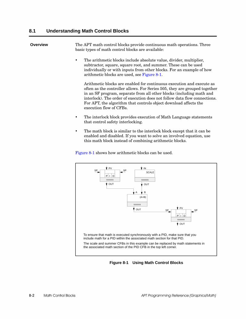
Math Control Blocks8-2 APT Programming Reference (Graphics/Math)
8.1 Understanding Math Control Blocks
The APT math control blocks provide continuous math operations. Threebasic types of math control blocks are available:
The arithmetic blocks include absolute value, divider, multiplier,subtractor, square, square root, and summer. These can be usedindividually or with inputs from other blocks. For an example of howarithmetic blocks are used, see Figure 8-1.
Arithmetic blocks are enabled for continuous execution and execute asoften as the controller allows. For Series 505, they are grouped togetherin an SF program, separate from all other blocks (including math andinterlock). The order of execution does not follow data flow connections.For APT, the algorithm that controls object download affects theexecution flow of CFBs.
The interlock block provides execution of Math Language statementsthat control safety interlocking.
The math block is similar to the interlock block except that it can beenabled and disabled. If you want to solve an involved equation, usethis math block instead of combining arithmetic blocks.
Figure 8-1 shows how arithmetic blocks can be used.
P I D
OUT
PVSPSP
xxxxxx
P I D
OUT
PVSPSP
xxxxxx
OUT
xxxxxx
(A+B)
A B
IN
xxxxxx
SCALE
OUT
To ensure that math is executed synchronously with a PID, make sure that youinclude math for a PID within the associated math section for that PID.
The scale and summer CFBs in this example can be replaced by math statements inthe associated math section of the PID CFB in the top left corner.
Figure 8-1 Using Math Control Blocks
Overview

Math Control Blocks 8-3APT Programming Reference (Graphics/Math)
The arithmetic, interlock, and math blocks are supported for Series 505 andS5 controllers. For 560/560T controllers, math blocks and interlock blocksare supported; arithmetic blocks are not.
For S5 controllers, APT automatically compiles all math operations intoSTL code, whereas the type of code used for Series 505 controllers (RLL orSFPGM) depends on the math operation being performed. In cases where anoperation can be performed using either RLL or SFPGM, you have theoption to specify what type of code APT uses for compile.
See Chapter 10 for more information about how APT compiles math blocksinto STL, RLL, and SFPGM code.
Availability
Math Control Blocks8-4 APT Programming Reference (Graphics/Math)
Understanding Math Control Blocks (continued)
The inputs to math control blocks can be analog inputs, integers, or realnumbers.
The interlock block has no inputs or outputs.
Inputs to the math block can be any combination of integers, realnumbers, or empty fields.
For S5 controllers, inputs to the absolute value, divider, multiplier,subtractor, square, square root, and summer blocks must all be thesame type, i.e., all integer or all float.
If the .OUT extension variable is an integer and the inputs are notintegers, .OUT is assigned the appropriate value rounded to the nearestinteger.
Math control blocks provide no scaling on analog outputs.
Inputs and Outputs
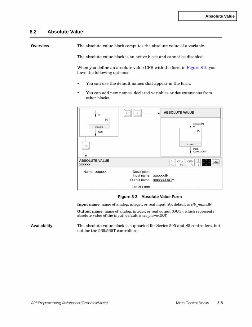
Absolute Value
Math Control Blocks 8-5APT Programming Reference (Graphics/Math)
8.2 Absolute Value
The absolute value block computes the absolute value of a variable.
The absolute value block is an active block and cannot be disabled.
When you define an absolute value CFB with the form in Figure 8-2, youhave the following options:
You can use the default names that appear in the form.
You can add new names: declared variables or dot extensions fromother blocks.
Name: xxxxxx Description:Input name: xxxxxx.IN
Output name: xxxxxx.OUTS
-- -- -- -- -- -- -- -- -- -- -- -- -- -- -- -- -- End of Form -- -- -- -- -- -- -- -- -- -- -- -- -- -- -- -- -- --
OUTxxxxxx.OUT
ABSOLUTE VALUE
xxxxxx.INA
ABSOLUTE VALUExxxxxx
?F1
ESCCTLsF2
OPTsF3
xxxxxx
xxxxxx|A|
|A|
OUT
A
Figure 8-2 Absolute Value Form
Input name: name of analog, integer, or real input (A); default is cfb_name.IN.
Output name: name of analog, integer, or real output (OUT), which representsabsolute value of the input; default is cfb_name.OUT.
The absolute value block is supported for Series 505 and S5 controllers, butnot for the 560/560T controllers.
Overview
Availability
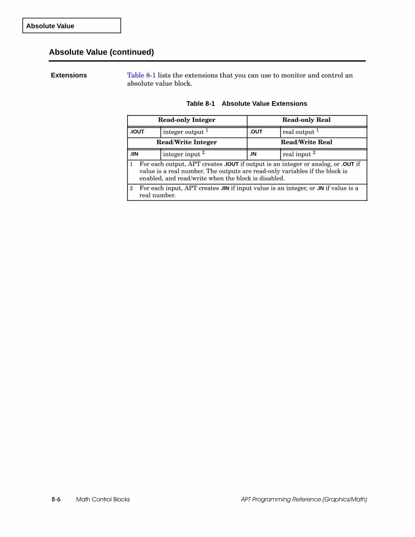
Absolute Value
Math Control Blocks8-6 APT Programming Reference (Graphics/Math)
Absolute Value (continued)
Table 8-1 lists the extensions that you can use to monitor and control anabsolute value block.
Table 8-1 Absolute Value Extensions
Read-only Integer Read-only Real
.IOUT integer output 1 .OUT real output 1
Read/Write Integer Read/Write Real
.IIN integer input 2 .IN real input 2
1 For each output, APT creates .IOUT if output is an integer or analog, or .OUT ifvalue is a real number. The outputs are read-only variables if the block isenabled, and read/write when the block is disabled.
2 For each input, APT creates .IIN if input value is an integer, or .IN if value is areal number.
Extensions
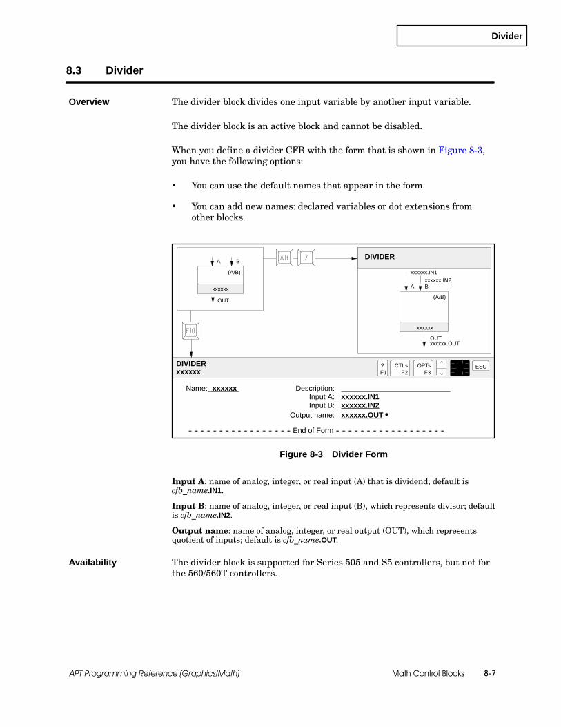
Divider
Math Control Blocks 8-7APT Programming Reference (Graphics/Math)
8.3 Divider
The divider block divides one input variable by another input variable.
The divider block is an active block and cannot be disabled.
When you define a divider CFB with the form that is shown in Figure 8-3,you have the following options:
You can use the default names that appear in the form.
You can add new names: declared variables or dot extensions fromother blocks.
Name: xxxxxx Description:Input A: xxxxxx.IN1Input B: xxxxxx.IN2
Output name: xxxxxx.OUT S
-- -- -- -- -- -- -- -- -- -- -- -- -- -- -- -- -- End of Form -- -- -- -- -- -- -- -- -- -- -- -- -- -- -- -- -- --
OUTxxxxxx.OUT
DIVIDER
DIVIDERxxxxxx
?F1
ESCCTLsF2
OPTsF3
OUT
xxxxxx
xxxxxx(A/B)
(A/B)
A B
A Bxxxxxx.IN2
xxxxxx.IN1
Figure 8-3 Divider Form
Input A: name of analog, integer, or real input (A) that is dividend; default iscfb_name.IN1.
Input B: name of analog, integer, or real input (B), which represents divisor; defaultis cfb_name.IN2.
Output name: name of analog, integer, or real output (OUT), which representsquotient of inputs; default is cfb_name.OUT.
The divider block is supported for Series 505 and S5 controllers, but not forthe 560/560T controllers.
Overview
Availability
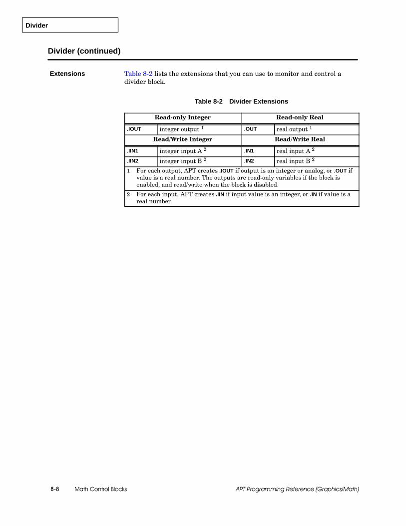
Divider
Math Control Blocks8-8 APT Programming Reference (Graphics/Math)
Divider (continued)
Table 8-2 lists the extensions that you can use to monitor and control adivider block.
Table 8-2 Divider Extensions
Read-only Integer Read-only Real
.IOUT integer output 1 .OUT real output 1
Read/Write Integer Read/Write Real
.IIN1 integer input A 2 .IN1 real input A 2
.IIN2 integer input B 2 .IN2 real input B 2
1 For each output, APT creates .IOUT if output is an integer or analog, or .OUT ifvalue is a real number. The outputs are read-only variables if the block isenabled, and read/write when the block is disabled.
2 For each input, APT creates .IIN if input value is an integer, or .IN if value is areal number.
Extensions

Interlock
Math Control Blocks 8-9APT Programming Reference (Graphics/Math)
8.4 Interlock
The interlock block allows you to use the Math Language to create a CFBthat executes continuously. The interlock block is a continuous block thathas no inputs or outputs and that cannot be disabled.
NOTE: If you place an INIT section in an interlock block, the INIT sectionexecutes only on the first scan following a transition to RUN mode afterdownload (one time only).
The interlock block allows you to write device-override control, or to definespecial devices. An interlock is typically used to force a device to a knownstate without regard to any step commands or assignments from other mathblocks. An interlock block begins executing as soon as the controller changesto RUN mode.
High-priority interlocks are executed before SFCs, other CFBs, and devices.Low-priority interlocks are executed after devices. Refer to Chapter 2 in theSIMATIC APT Applications Manual for more details.
Figure 8-4 shows the form that you use to define an interlock block.
Name: xxxxxx Description:Priority type: HIGH LOWPress F10 to edit math text
-- -- -- -- -- -- -- -- -- -- -- -- -- -- -- -- -- End of Form -- -- -- -- -- -- -- -- -- -- -- -- -- -- -- -- -- --
INTERLOCK
INTERLOCKxxxxxx
?F1
ESCCTLsF2
OPTsF3
xxxxxx
xxxxxxINTERLOCK
INTERLOCK
Figure 8-4 Interlock Form
Priority type: default is HIGH.
The interlock block is supported for all controllers.
Overview
Availability

Interlock
Math Control Blocks8-10 APT Programming Reference (Graphics/Math)
Interlock (continued)
You can select a priority type of either high or low.
High-priority interlock blocks execute before any step or device logic.Because high-priority blocks are executed before any devices areenabled, they are commonly used for internal validation checks. Forexample, you might use this block to ensure that a valve is enabledbefore a motor is started.
The following math code insures that the valve is always closed unlessthe motor is running.
valve1.NRDY := motor1.STPPD
The .NRDY bit of the valve depends on the state of the motor (runningor stopped).
Low-priority interlock blocks execute in the device section of RLL andexecute after all SFC step commands. They have the same priority levelas devices. They may be used, for example, to create your own devicesto supplement the pre-programmed devices that are supplied with APT.
NOTE: For Series 505 controllers, a high or low priority affects an interlockblock only if that block is composed entirely of RLL code. If a block containsany SFPGM code, the selection of high or low priority has no effect on theexecution of that block. (See page 10-4 in Chapter 10, “Math LanguageOverview,” for more information on RLL and SFPGM code.)
Priorities
Math
Math Control Blocks 8-11APT Programming Reference (Graphics/Math)
8.5 Math
The math block allows you to use the full power and flexibility of the MathLanguage to write your own controller code. See Chapter 10, “MathLanguage Overview,” and Chapter 11, “Math Functions and Procedures,” foran explanation of the Math Language.
The math block is supported for all controllers.
A math block executes only when enabled. The speed of execution isdetermined both by the controller and by the type of code generated. Allprogramming is done in STL for S5 controllers. However, if you have aSeries 505 controller, your execution speed depends on the type of code usedto perform your math operations. RLL executes more quickly than SFPGM.
For a Series 505 controller, RLL is generated for the block if alloperations are boolean, integer, or real number assignments, as shownin the following examples:
real_variable := 5.0 ;real_variable1 := real_variable2;array1[1] := 5;
For a Series 505 controller, SFPGM code is generated when you useany real-number operations, or when you use any SF address types,such as T-memory direct addresses, as shown in the followingexamples:
real_variable := 5.0 * real_variable;array2[int_variable] := 5;%T10 := 1;
If you have a Series 505 controller, balance your code between RLL andSFPGM in order to maximize controller utilization.
Overview
Availability
Controlling Speedof Series 505 MathExecution

Math
Math Control Blocks8-12 APT Programming Reference (Graphics/Math)
Math (continued)
Figure 8-5 shows the form that you use to define a math block. You canselect from the following types: continuous, event, sampled, or active.
A continuous block executes repeatedly, as often as possible.
An event block executes only once. To repeat the execution of an eventblock, you must disable and then enable the block again. You might usean event block to generate a report or to total the ingredients at theend of a batch. For Series 505 controllers, this type of math blockshould not contain an INIT section, because only the INIT section willexecute.
A sampled block executes at intervals that you specify. The sample timeis a compiled variable that cannot be changed at run time. The sampletime is a read-only real value that is stored at address “%T4” for aSeries 505 controller performing an SFPGM math operation, or ataddress CFBname.NNL.PRE for an S5 controller or a Series 505controller performing an RLL math operation. For S5 controllers, thesample time value is in tenths of seconds.
An active block is continuously active and cannot be turned off. Anactive block is similar to an interlock block of low priority.
! WARNINGAn event math block will be queued for execution if the enable for the block wasset when the controller transitions to the RUN mode.
Control devices can operate in an unpredictable manner and fail in an unsafecondition that could result in death or serious injury to personnel, and/ordamage to equipment.
The enable for the event math block needs to be reset to false immediately afterthe block finishes execution. Design your code to handle enabling anddisabling of the math block enable after a transition to RUN mode.
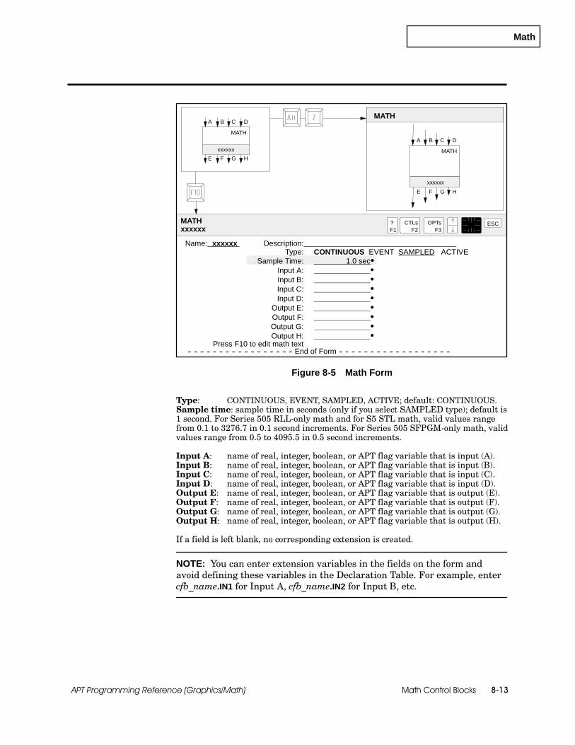
Math
Math Control Blocks 8-13APT Programming Reference (Graphics/Math)
MATH
MATHxxxxxx
?F1
ESCCTLsF2
OPTsF3
A
xxxxxx
xxxxxx MATH
MATH
B C D
E F G H
A B C D
E F G H
Name: xxxxxx Description:Type: CONTINUOUS EVENT SAMPLED ACTIVE
Sample Time: 1.0 secSInput A: SInput B: SInput C: SInput D: S
Output E: SOutput F: SOutput G: SOutput H: S
Press F10 to edit math text-- -- -- -- -- -- -- -- -- -- -- -- -- -- -- -- -- End of Form -- -- -- -- -- -- -- -- -- -- -- -- -- -- -- -- -- --
Figure 8-5 Math Form
Type: CONTINUOUS, EVENT, SAMPLED, ACTIVE; default: CONTINUOUS.Sample time: sample time in seconds (only if you select SAMPLED type); default is1 second. For Series 505 RLL-only math and for S5 STL math, valid values rangefrom 0.1 to 3276.7 in 0.1 second increments. For Series 505 SFPGM-only math, validvalues range from 0.5 to 4095.5 in 0.5 second increments.
Input A: name of real, integer, boolean, or APT flag variable that is input (A).Input B: name of real, integer, boolean, or APT flag variable that is input (B).Input C: name of real, integer, boolean, or APT flag variable that is input (C).Input D: name of real, integer, boolean, or APT flag variable that is input (D).Output E: name of real, integer, boolean, or APT flag variable that is output (E).Output F: name of real, integer, boolean, or APT flag variable that is output (F).Output G: name of real, integer, boolean, or APT flag variable that is output (G).Output H: name of real, integer, boolean, or APT flag variable that is output (H).
If a field is left blank, no corresponding extension is created.
NOTE: You can enter extension variables in the fields on the form andavoid defining these variables in the Declaration Table. For example, entercfb_name.IN1 for Input A, cfb_name.IN2 for Input B, etc.
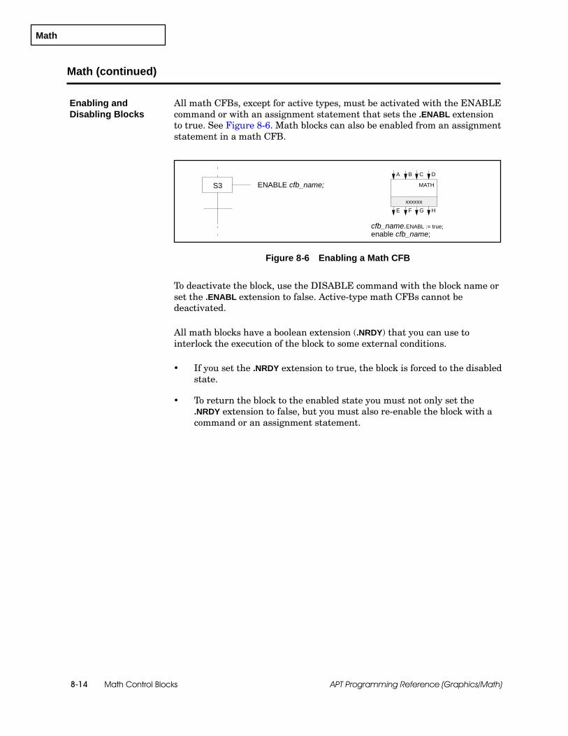
Math
Math Control Blocks8-14 APT Programming Reference (Graphics/Math)
Math (continued)
All math CFBs, except for active types, must be activated with the ENABLEcommand or with an assignment statement that sets the .ENABL extensionto true. See Figure 8-6. Math blocks can also be enabled from an assignmentstatement in a math CFB.
cfb_name.ENABL := true;enable cfb_name;
S3 ENABLE cfb_name;A
xxxxxx
MATH
B C D
E F G H
Figure 8-6 Enabling a Math CFB
To deactivate the block, use the DISABLE command with the block name orset the .ENABL extension to false. Active-type math CFBs cannot bedeactivated.
All math blocks have a boolean extension (.NRDY) that you can use tointerlock the execution of the block to some external conditions.
If you set the .NRDY extension to true, the block is forced to the disabledstate.
To return the block to the enabled state you must not only set the.NRDY extension to false, but you must also re-enable the block with acommand or an assignment statement.
Enabling andDisabling Blocks

Math
Math Control Blocks 8-15APT Programming Reference (Graphics/Math)
Table 8-3 lists the commands that determine the mode of operation for themath block.
Table 8-3 Math Commands
Command Description
ENABLE (ENA) Turns on, or activates, the block.
DISABLE (DIS) Turns off, or deactivates, the block.
Table 8-4 lists the extensions that you can use to monitor and control amath block.
Table 8-4 Math Extensions
Read-only Boolean Read-only Integer 4 Read-only Real 4
.ENABLD enabled 2 .IOUTE integer output E 5 .OUTE real output E 5
.DOUTE boolean output E .IOUTF integer output F 5 .OUTF real output F 5
.DOUTF boolean output F .IOUTG integer output G 5 .OUTG real output G 5
.DOUTG boolean output G .IOUTH integer output H 5 .OUTH real output H 5
.DOUTH boolean output H .SNUM error line number 7
.ECODE error code 7
.IID error controller block 7
Read/Write Boolean Read/Write Integer 4 Read/Write Real 4
.ENABL enable 1,2 .IINA integer input A 6 .INA real input A 6
.NRDY not ready 2 .IINB integer input B 6 .INB real input B 6
.REN request enable 3 .IINC integer input C 6 .INC real input C 6
.RDIS request disable 3 .IIND integer input D 6 .IND real input D 6
.DINA boolean input A
.DINB boolean input B
.DINC boolean input C
.DIND boolean input D
1 This extension is manipulated by the command(s) associated with the block.
2 These extensions do not exist for active-type math CFBs.
3 These booleans are APT flags that are manipulated by the Math procedures Latch, Clear, and On.
4 The extensions with the numbered inputs or outputs supported in earlier APT software releases (.IOUT1,.IOUT2, etc., .OUT1, .OUT2, etc., .IIN1, .IIN2, etc., .IN1, .IN2, etc.) are still supported.
5 For each output, APT creates .IOUT if output is an integer or analog, or .OUT if value is a real number. Theoutputs are read-only variables if the block is enabled, and read/write when the block is disabled.
6 For each input, APT creates .IIN if input value is an integer, or .IN if value is a real number.
7 These extensions do not contain error codes for S5 controllers. (Series 505-only error codes)
Commands andExtensions

Multiplier
Math Control Blocks8-16 APT Programming Reference (Graphics/Math)
8.6 Multiplier
The multiplier block multiplies one input variable by another inputvariable.
The multiplier block is an active block and cannot be disabled.
When you define a multiplier CFB with the form in Figure 8-7, you have thefollowing options:
You can use the default names that appear in the form.
You can add new names: declared variables or dot extensions fromother blocks.
Name: xxxxxx Description:Input A: xxxxxx.IN1Input B: xxxxxx.IN2
Output name: xxxxxx.OUT S
-- -- -- -- -- -- -- -- -- -- -- -- -- -- -- -- -- End of Form -- -- -- -- -- -- -- -- -- -- -- -- -- -- -- -- -- --
OUTxxxxxx.OUT
MULTIPLIER
MULTIPLIERxxxxxx
?F1
ESCCTLsF2
OPTsF3
OUT
xxxxxx
xxxxxx(AxB)
(AxB)
A B
Bxxxxxx.IN2
A
xxxxxx.IN1
Figure 8-7 Multiplier Form
Input A: name of analog, integer, or real that is first input (A), which representsmultiplicand; default is cfb_name.IN1.
Input B: name of analog, integer, or real that is second input (B), which representsmultiplier; default is cfb_name.IN2.
Output name: name of analog, integer, or real output (OUT), which representsproduct of inputs; default is cfb_name.OUT.
The multiplier block is supported for Series 505 and S5 controllers, but notfor the 560/560T controllers.
Overview
Availability

Multiplier
Math Control Blocks 8-17APT Programming Reference (Graphics/Math)
Table 8-5 lists the extensions that you can use to monitor and control amultiplier block.
Table 8-5 Multiplier Extensions
Read-only Integer Read-only Real
.IOUT integer output 1 .OUT real output 1
Read/Write Integer Read/Write Real
.IIN1 integer input A 2 .IN1 real input A 2
.IIN2 integer input B 2 .IN2 real input B 2
1 For each output, APT creates .IOUT if output value is an integer or analog, or.OUT if value is a real number. The outputs are read-only variables if the blockis enabled, and read/write when the block is disabled.
2 For each input, APT creates .IIN if input value is an integer, or .IN if value is areal number.
Extensions

Square
Math Control Blocks8-18 APT Programming Reference (Graphics/Math)
8.7 Square
The square block computes the square of a variable.
The square block is an active block and cannot be disabled.
When you define a square CFB with the form in Figure 8-8, you have thefollowing options:
You can use the default names that appear in the form.
You can add new names: declared variables or dot extensions fromother blocks.
Name: xxxxxx Description:Input name: xxxxxx.IN
Output name: xxxxxx.OUT S
-- -- -- -- -- -- -- -- -- -- -- -- -- -- -- -- -- End of Form -- -- -- -- -- -- -- -- -- -- -- -- -- -- -- -- -- --
OUT
SQUARE
xxxxxx.OUT
xxxxxx.INA
SQUARExxxxxx
?F1
ESCCTLsF2
OPTsF3
OUT
A
xxxxxx
xxxxxx
2A
2A
Figure 8-8 Square Form
Input name: name of analog, integer, or real input (A); default is cfb_name.IN.
Output name: name of analog, integer, or real output (OUT) that representssquare of input; default is cfb_name.OUT.
The square block is supported for Series 505 and S5 controllers, but not forthe 560/560T controllers.
Overview
Availability

Square
Math Control Blocks 8-19APT Programming Reference (Graphics/Math)
Table 8-6 lists the extensions that you can use to monitor and control asquare block.
Table 8-6 Square Extensions
Read-only Integer Read-only Real
.IOUT integer output 1 .OUT output 1
Read/Write Integer Read/Write Real
.IIN integer input 2 .IN real input 2
1 For each output, APT creates .IOUT if output value is an integer or analog, or.OUT if value is a real number. The outputs are read-only variables if the blockis enabled, and read/write when the block is disabled.
2 For each input, APT creates .IIN if input value is an integer, or .IN if value is areal number.
Extensions

Square Root
Math Control Blocks8-20 APT Programming Reference (Graphics/Math)
8.8 Square Root
The square root block computes the square root of a variable. The inputmust be a positive real number; otherwise,the output is invalid.
The square root block is an active block and cannot be disabled.
When you define a square root CFB with the form in Figure 8-9, you havethe following options:
You can use the default names that appear in the form.
You can add new names: declared variables or dot extensions fromother blocks.
OUTxxxxxx.OUT
SQUARE ROOT
xxxxxx.INA
SQUARE ROOTxxxxxx
?F1
ESCCTLsF2
OPTsF3
OUT
A
xxxxxx
xxxxxx
A
A
Name: xxxxxx Description:Input name: xxxxxx.IN
Output name: xxxxxx.OUT S
-- -- -- -- -- -- -- -- -- -- -- -- -- -- -- -- -- End of Form -- -- -- -- -- -- -- -- -- -- -- -- -- -- -- -- -- --
Figure 8-9 Square Root Form
Input name: name of analog, integer, or real input (A); default is cfb_name.IN.
Output name: name of analog, integer, or real output (OUT), which representssquare root of the input; default is cfb_name.OUT.
The square root block is supported for Series 505 and S5 controllers, but notfor the 560/560T controllers.
Overview
Availability
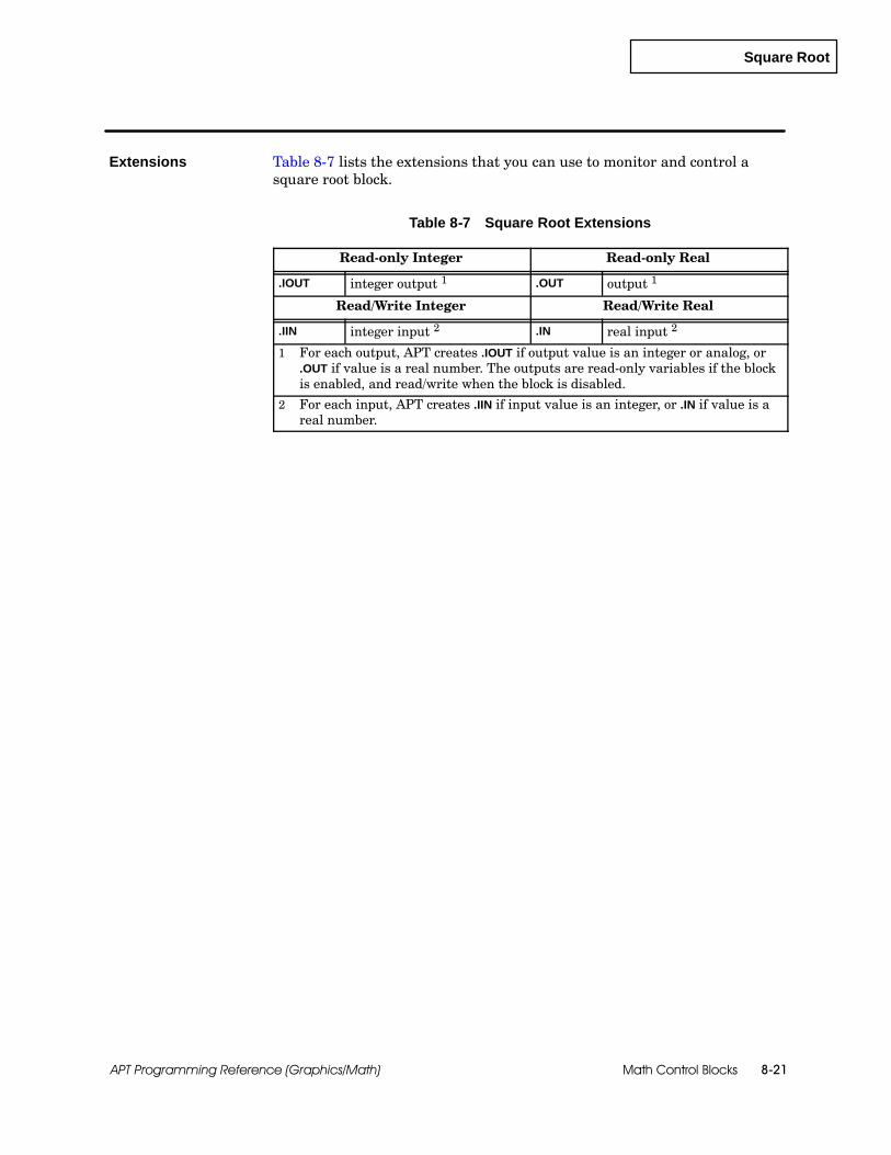
Square Root
Math Control Blocks 8-21APT Programming Reference (Graphics/Math)
Table 8-7 lists the extensions that you can use to monitor and control asquare root block.
Table 8-7 Square Root Extensions
Read-only Integer Read-only Real
.IOUT integer output 1 .OUT output 1
Read/Write Integer Read/Write Real
.IIN integer input 2 .IN real input 2
1 For each output, APT creates .IOUT if output value is an integer or analog, or.OUT if value is a real number. The outputs are read-only variables if the blockis enabled, and read/write when the block is disabled.
2 For each input, APT creates .IIN if input value is an integer, or .IN if value is areal number.
Extensions

Subtractor
Math Control Blocks8-22 APT Programming Reference (Graphics/Math)
8.9 Subtractor
The subtractor block subtracts one input variable from another inputvariable.
The subtractor block is an active block and cannot be disabled.
When you define a subtractor CFB with the form in Figure 8-10, you havethe following options:
You can use the default names that appear in the form.
You can add new names: declared variables or dot extensions fromother blocks.
Name: xxxxxx Description:Input A: xxxxxx.IN1Input B: xxxxxx.IN2
Output name: xxxxxx.OUT S
-- -- -- -- -- -- -- -- -- -- -- -- -- -- -- -- -- End of Form -- -- -- -- -- -- -- -- -- -- -- -- -- -- -- -- -- --
OUTxxxxxx.OUT
SUBTRACTOR
SUBTRACTORxxxxxx
?F1
ESCCTLsF2
OPTsF3
OUT
xxxxxx
xxxxxx(A--B)
(A--B)
A B
Bxxxxxx.IN2
A
xxxxxx.IN1
Figure 8-10 Subtractor Form
Input A: name of analog, integer, or real that is first input (A), which representsminuend; default is cfb_name.IN1.
Input B: name of analog, integer, or real that is second input (B), which representssubtrahend; default is cfb_name.IN2.
Output name: name of analog, integer, or real output (OUT), which representsdifference of inputs; default is cfb_name.OUT.
The subtractor block is supported for Series 505 and S5 controllers, but notfor the 560/560T controllers.
Overview
Availability
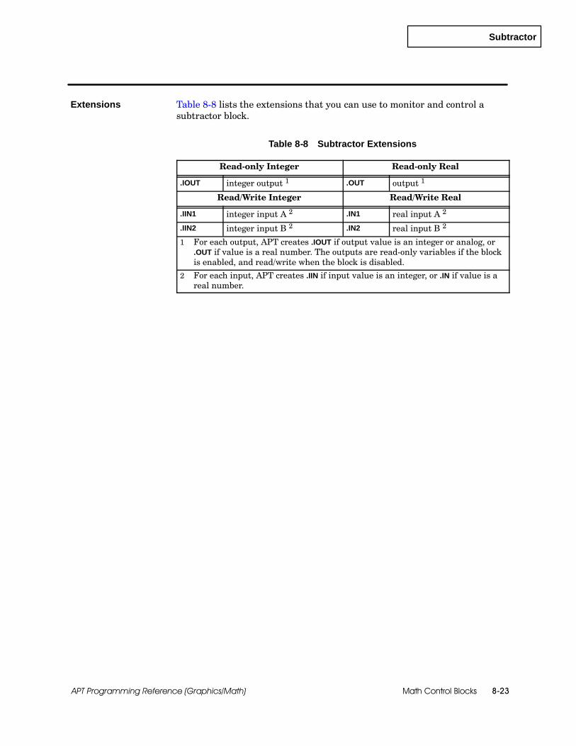
Subtractor
Math Control Blocks 8-23APT Programming Reference (Graphics/Math)
Table 8-8 lists the extensions that you can use to monitor and control asubtractor block.
Table 8-8 Subtractor Extensions
Read-only Integer Read-only Real
.IOUT integer output 1 .OUT output 1
Read/Write Integer Read/Write Real
.IIN1 integer input A 2 .IN1 real input A 2
.IIN2 integer input B 2 .IN2 real input B 2
1 For each output, APT creates .IOUT if output value is an integer or analog, or.OUT if value is a real number. The outputs are read-only variables if the blockis enabled, and read/write when the block is disabled.
2 For each input, APT creates .IIN if input value is an integer, or .IN if value is areal number.
Extensions

Summer
Math Control Blocks8-24 APT Programming Reference (Graphics/Math)
8.10 Summer
The summer block adds one input variable to another input variable.
The summer block is an active block and cannot be disabled.
When you define a summer CFB with the form in Figure 8-11, you have thefollowing options:
You can use the default names that appear in the form.
You can add new names: declared variables or dot extensions fromother blocks.
Name: xxxxxx Description:Input A: xxxxxx.IN1Input B: xxxxxx.IN2
Output name: xxxxxx.OUT S
-- -- -- -- -- -- -- -- -- -- -- -- -- -- -- -- -- End of Form -- -- -- -- -- -- -- -- -- -- -- -- -- -- -- -- -- --
OUTxxxxxx.OUT
SUMMER
SUMMERxxxxxx
?F1
ESCCTLsF2
OPTsF3
OUT
xxxxxx
xxxxxx(A+B)
(A+B)
A B
Bxxxxxx.IN2
A
xxxxxx.IN1
Figure 8-11 Summer Form
Input A: name of analog, integer, or real that is first input (A), which represents thefirst addend; default is cfb_name.IN1.
Input B: name of analog, integer, or real second input (B), which represents thesecond addend; default is cfb_name.IN2.
Output name: name of analog, integer, or real output (OUT), which represents thesum of the inputs; default is cfb_name.OUT.
The summer block is supported for Series 505 and S5 controllers, but not forthe 560/560T controllers.
Overview
Availability

Summer
Math Control Blocks 8-25APT Programming Reference (Graphics/Math)
Table 8-9 lists the extensions that you can use to monitor and control asummer block.
Table 8-9 Summer Extensions
Read-only Integer Read-only Real
.IOUT integer output 1 .OUT output 1
Read/Write Integer Read/Write Real
.IIN1 integer input A 2 .IN1 real input A 2
.IIN2 integer input B 2 .IN2 real input B 2
1 For each output, APT creates .IOUT if output value is an integer or analog, or.OUT if value is a real number. The outputs are read-only variables if the blockis enabled, and read/write when the block is disabled.
2 For each input, APT creates .IIN if input value is an integer, or .IN if value is areal number.
Extensions

Other Control Blocks 9-1APT Programming Reference (Graphics/Math)
Chapter 9
Other Control Blocks
9.1 Understanding Other Control Blocks 9-2. . . . . . . . . . . . . . . . . . . . . . . . . . . . . . . . . . . . . . . . . . . .Overview 9-2. . . . . . . . . . . . . . . . . . . . . . . . . . . . . . . . . . . . . . . . . . . . . . . . . . . . . . . . . . . . . . . . . . . . . . .Availability 9-2. . . . . . . . . . . . . . . . . . . . . . . . . . . . . . . . . . . . . . . . . . . . . . . . . . . . . . . . . . . . . . . . . . . . . .Enabling and Disabling Blocks 9-2. . . . . . . . . . . . . . . . . . . . . . . . . . . . . . . . . . . . . . . . . . . . . . . . . . . .
9.2 Anti-Reset Windup Protection/Constraint Type 9-3. . . . . . . . . . . . . . . . . . . . . . . . . . . . . . . . . . .Overview 9-3. . . . . . . . . . . . . . . . . . . . . . . . . . . . . . . . . . . . . . . . . . . . . . . . . . . . . . . . . . . . . . . . . . . . . . .Availability 9-3. . . . . . . . . . . . . . . . . . . . . . . . . . . . . . . . . . . . . . . . . . . . . . . . . . . . . . . . . . . . . . . . . . . . . .Block Configuration 9-4. . . . . . . . . . . . . . . . . . . . . . . . . . . . . . . . . . . . . . . . . . . . . . . . . . . . . . . . . . . . . .Commands and Extensions 9-5. . . . . . . . . . . . . . . . . . . . . . . . . . . . . . . . . . . . . . . . . . . . . . . . . . . . . . .
9.3 Anti-Reset Windup Protection/Select Type 9-6. . . . . . . . . . . . . . . . . . . . . . . . . . . . . . . . . . . . . . .Overview 9-6. . . . . . . . . . . . . . . . . . . . . . . . . . . . . . . . . . . . . . . . . . . . . . . . . . . . . . . . . . . . . . . . . . . . . . .Availability 9-6. . . . . . . . . . . . . . . . . . . . . . . . . . . . . . . . . . . . . . . . . . . . . . . . . . . . . . . . . . . . . . . . . . . . . .Block Configuration 9-7. . . . . . . . . . . . . . . . . . . . . . . . . . . . . . . . . . . . . . . . . . . . . . . . . . . . . . . . . . . . . .Commands and Extensions 9-8. . . . . . . . . . . . . . . . . . . . . . . . . . . . . . . . . . . . . . . . . . . . . . . . . . . . . . .
9.4 Correlated Lookup Table 9-9. . . . . . . . . . . . . . . . . . . . . . . . . . . . . . . . . . . . . . . . . . . . . . . . . . . . . . . .Overview 9-9. . . . . . . . . . . . . . . . . . . . . . . . . . . . . . . . . . . . . . . . . . . . . . . . . . . . . . . . . . . . . . . . . . . . . . .Availability 9-9. . . . . . . . . . . . . . . . . . . . . . . . . . . . . . . . . . . . . . . . . . . . . . . . . . . . . . . . . . . . . . . . . . . . . .Block Configuration 9-9. . . . . . . . . . . . . . . . . . . . . . . . . . . . . . . . . . . . . . . . . . . . . . . . . . . . . . . . . . . . . .Commands and Extensions 9-12. . . . . . . . . . . . . . . . . . . . . . . . . . . . . . . . . . . . . . . . . . . . . . . . . . . . . . .
9.5 Scale 9-13. . . . . . . . . . . . . . . . . . . . . . . . . . . . . . . . . . . . . . . . . . . . . . . . . . . . . . . . . . . . . . . . . . . . . . . . . .Overview 9-13. . . . . . . . . . . . . . . . . . . . . . . . . . . . . . . . . . . . . . . . . . . . . . . . . . . . . . . . . . . . . . . . . . . . . . .Availability 9-13. . . . . . . . . . . . . . . . . . . . . . . . . . . . . . . . . . . . . . . . . . . . . . . . . . . . . . . . . . . . . . . . . . . . . .Block Configuration 9-13. . . . . . . . . . . . . . . . . . . . . . . . . . . . . . . . . . . . . . . . . . . . . . . . . . . . . . . . . . . . . .Commands and Extensions 9-15. . . . . . . . . . . . . . . . . . . . . . . . . . . . . . . . . . . . . . . . . . . . . . . . . . . . . . .

Other Control Blocks9-2 APT Programming Reference (Graphics/Math)
9.1 Understanding Other Control Blocks
APT provides several other functions that are available as continuousfunction blocks.
Anti-reset windup protection blocks allow you to monitor a variable andprovide reset windup protection in addition to that provided by the PIDblock.
The correlated lookup table determines an output value based on therelationship between an input and two 11-element arrays.
The scale block converts an input value to an output that is within thespecified range.
All of the functions above are supported for Series 505 and S5 controllers.None of the functions listed above are supported for the 560/560Tcontrollers.
These CFBs must be activated with the ENABLE command, or with anassignment statement that sets the .ENABL extension to true. SeeFigure 9-1. These blocks can also be enabled from an assignment statementin a math CFB.
cfb_name.ENABL := true;Enable cfb_name;
S3 ENABLE cfb_name;A
xxxxxx
MATH
B C D
E F G H
Figure 9-1 Enabling a CFB
To deactivate the block, use the DISABLE command with the block name, orset the .ENABL extension to false.
These control blocks have a boolean extension (.NRDY) that you can use tointerlock the execution of the block to some external conditions.
If you set the .NRDY extension to true, the block is forced to the disabledstate.
To return the block to the enabled state you must not only set the.NRDY extension to false, but you must also re-enable the block with acommand or an assignment statement.
Overview
Availability
Enabling andDisabling Blocks

Anti-Reset Windup Protection/Constraint
Other Control Blocks 9-3APT Programming Reference (Graphics/Math)
9.2 Anti-Reset Windup Protection/Constraint Type
The anti-reset windup protection/constraint type block protects the integralmode of a PID loop from windup by ensuring that a monitored variableremains within specified limits.
This block can be used when constraints within the control loop can bereached without being detected by the anti-reset windup protection that isinternal to the PID block. This block is useful when you have two cascadedloops and the output of the source loop is greater than the output of thesecond loop.
The input to the block is the analog or real value that you want to monitor.
When the protected PID is in automatic or cascade mode and the constraintblock is enabled, the block compares the monitored variable (input) with thehigh and low limits that you specify when you define the constraint block.
The block freezes the bias (the integral term) of the protected PID asfollows:
If the monitored variable is within the limits, the current value of the.BIAS (bias) extension is stored internally; and the .AWS (anti-windupstatus) extension is set to 0 to indicate normal loop operation.
If the monitored variable goes below the value of the .LLIM (low limit)extension while the loop is still trying to decrease the output, theconstraint block freezes the bias at the last recorded value; and the.AWS extension is set to 1.
If the monitored variable exceeds the value of the .HLIM (high limit)extension while the loop is still trying to increase the output, theconstraint block freezes the bias at the last recorded value before theconstraint was exceeded; and the .AWS extension is set to 2.
To stop the integral mode from operating, assign 3 to the .AWSextension.
NOTE: If the PID loop executes faster than the anti-reset windupprotection/constraint CFB, then the CFB cannot protect the loop fromwindup. In this case, you must write code in the associated math section ofthe PID to provide the windup protection.
The anti-reset windup protection/constraint type block is supported forSeries 505 and S5 controllers, but not for the 560/560T controllers.
Overview
Availability

Anti-Reset Windup Protection/Constraint
Other Control Blocks9-4 APT Programming Reference (Graphics/Math)
Anti-Reset Windup Protection/Constraint (continued)
Figure 9-2 shows the form that you use to define the constraint type ofanti-reset windup protection.
ANTI-RESET WINDUP (CONSTRAINT TYPE)
Name: xxxxxx Description:Monitored variable: S
Protected loop:Low limit: 0.0High limit: 1.0
-- -- -- -- -- -- -- -- -- -- -- -- -- -- -- -- -- End of Form -- -- -- -- -- -- -- -- -- -- -- -- -- -- -- -- -- --
IN
ANTI-RESET WINDUP (CONSTRAINT TYPE)xxxxxx
?F1
ESCCTLsF2
OPTsF3
IN
xxxxxx
xxxxxx
EARWPCONSTRAIN
EARWPCONSTRAINT
Figure 9-2 Anti-Reset Windup (Constraint Type) Form
Name: unique name that identifies block (eight characters maximum); default isname that you entered when you created the CFB graphic.
Description: 30 characters maximum (optional)
Monitored variable: name of analog or real input that is monitored variable (.IN).
Protected loop: name of PID loop that is protected by this block.
Low limit: real number below which the monitored variable must not fall.
High limit: real number above which the monitored variable must not rise.
BlockConfiguration
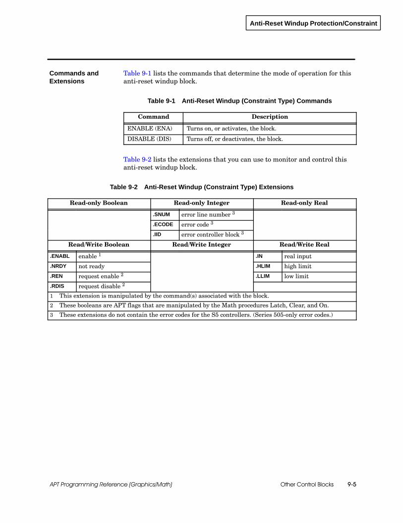
Anti-Reset Windup Protection/Constraint
Other Control Blocks 9-5APT Programming Reference (Graphics/Math)
Table 9-1 lists the commands that determine the mode of operation for thisanti-reset windup block.
Table 9-1 Anti-Reset Windup (Constraint Type) Commands
Command Description
ENABLE (ENA) Turns on, or activates, the block.
DISABLE (DIS) Turns off, or deactivates, the block.
Table 9-2 lists the extensions that you can use to monitor and control thisanti-reset windup block.
Table 9-2 Anti-Reset Windup (Constraint Type) Extensions
Read-only Boolean Read-only Integer Read-only Real
.SNUM error line number 3
.ECODE error code 3
.IID error controller block 3
Read/Write Boolean Read/Write Integer Read/Write Real
.ENABL enable 1 .IN real input
.NRDY not ready .HLIM high limit
.REN request enable 2 .LLIM low limit
.RDIS request disable 2
1 This extension is manipulated by the command(s) associated with the block.
2 These booleans are APT flags that are manipulated by the Math procedures Latch, Clear, and On.
3 These extensions do not contain the error codes for the S5 controllers. (Series 505-only error codes.)
Commands andExtensions
Anti-Reset Windup Protection/Select
Other Control Blocks9-6 APT Programming Reference (Graphics/Math)
9.3 Anti-Reset Windup Protection/Select Type
The anti-reset windup protection/select type block protects the integralmode of a PID loop from windup by ensuring that the output of the PID loopremains equal to the value of a monitored variable.
This block can be used when a PID loop does not have a direct path to thecontrolled variable. For example, if you have a selector block monitoring theoutput of two PID blocks, you can use two select type anti-reset windupblocks to compare the output of the selector block with each PID output.
The input to the block is the analog or real value that you want to monitor.
When the protected PID loop is in automatic or cascade mode and the selectblock is enabled, the block compares the monitored variable (input) to theoutput of the loop that you specify.
The block freezes the bias (the integral term) of the protected PID asfollows:
If the monitored variable and output do agree, the current value of the.BIAS (bias) extension is stored internally; and the .AWS (anti-windupstatus) extension is set to 0 to indicate normal loop operation.
If the monitored variable and output do not agree, the select block setsthe bias equal to the monitored variable; and the .AWS extension is setto 3.
NOTE: If the PID loop executes faster than the anti-reset windupprotection/select CFB, then the CFB cannot protect the loop from windup.In this case, you must write code in the associated math section of the PIDto provide the windup protection.
The anti-reset windup protection/select type block is supported forSeries 505 and S5 controllers, but not for the 560/560T controllers.
Overview
Availability

Anti-Reset Windup Protection/Select
Other Control Blocks 9-7APT Programming Reference (Graphics/Math)
Figure 9-3 shows the form that you use to define the select type of anti-resetwindup protection.
ANTI-RESET WINDUP (SELECT TYPE)
Name: xxxxxx Description:Monitored variable: S
Protected loop:
-- -- -- -- -- -- -- -- -- -- -- -- -- -- -- -- -- End of Form -- -- -- -- -- -- -- -- -- -- -- -- -- -- -- -- -- --
IN
ANTI-RESET WINDUP (SELECT TYPE)xxxxxx
?F1
ESCCTLsF2
OPTsF3
IN
xxxxxx
xxxxxx
EARWPSELECT
EARWPSELECT
Figure 9-3 Anti-Reset Windup (Select Type) Form
Name: unique name that identifies block (eight characters maximum); default isname that you entered when you created the CFB graphic.
Description: 30 characters maximum (optional)
Monitored variable: name of analog, integer, or real input that is monitored input(IN).
Protected loop: name of PID loop that is protected by this block.
BlockConfiguration

Anti-Reset Windup Protection/Select
Other Control Blocks9-8 APT Programming Reference (Graphics/Math)
Anti-Reset Windup Protection/Select Type (continued)
Table 9-3 lists the commands that determine the mode of operation for thisanti-reset windup block.
Table 9-3 Anti-Reset Windup (Select Type) Commands
Command Description
ENABLE (ENA) Turns on, or activates, the block.
DISABLE (DIS) Turns off, or deactivates, the block.
Table 9-4 lists the extensions that you can use to monitor and control thisanti-reset windup block.
Table 9-4 Anti-Reset Windup (Select Type) Extensions
Read-only Boolean Read-only Integer Read-only Real
.SNUM error line number 3
.ECODE error code 3
.IID error controller block 3
Read/Write Boolean Read/Write Integer Read/Write Real
.ENABL enable 1 .IN real input
.NRDY not ready
.REN request enable 2
.RDIS request disable 2
1 This extension is manipulated by the command(s) associated with the block.
2 These booleans are APT flags that are manipulated by the Math procedures Latch, Clear, and On.
3 These extensions do not contain the error codes for the S5 controllers. (Series 505-only error codes.)
Commands andExtensions
Correlated Lookup Table
Other Control Blocks 9-9APT Programming Reference (Graphics/Math)
9.4 Correlated Lookup Table
The correlated lookup table block determines an output value based on therelationship between an input value and a specified range of values.
If the input is an integer, APT sends the appropriate value to theoutput.
If the input is a real number and the output is an analog value, APTassumes that the input is limited to the range of 0.0 to 1.0 andautomatically scales the output to the correct format (zero offset, 20%bias, or bipolar). If an input is outside this range, the output is set tothe maximum or minimum value of the subtype.
The input and output arrays must contain 11 elements. The values inthe input array must be arranged in ascending order.
The correlated lookup table type block is supported for Series 505 and S5controllers, but not for the 560/560T controllers.
You can select a type of either lookup or interpolation.
If you select Lookup, the block compares the input value to the values in theinput array, in sequence. The block determines the value of the output withone of the following techniques:
If the input value is equal to the value of an element of the input array,the output is assigned the value of the same element number in theoutput array.
If the input value is not equal to the value of an element of the inputarray, the block uses the value of the highest element of the input arraythat is not greater than the input value. The output is assigned thevalue of the same element number in the output array.
If the input value is less than the value of the first element of the inputarray, the output is assigned the value of the first element of the outputarray.
If the input value is greater than the value of any element of the inputarray, the output is assigned the value of the last element of the outputarray.
Overview
Availability
BlockConfiguration

Correlated Lookup Table
Other Control Blocks9-10 APT Programming Reference (Graphics/Math)
Correlated Lookup Table (continued)
If you select Interpolation, the block first compares the input value to thevalues in the input array. The block determines the value of the output withone of the following techniques:
If the input value is equal to the value of an element of the input array,the output is assigned the value of the same element number in theoutput array.
If the input value falls between the values of two elements of the inputarray, the output is assigned a value between the values of the sametwo element numbers in the output array. The value assigned to theoutput is interpolated between the values of the elements of the outputarray using the linear relationship calculated between the input valueand the values of the elements of the input array.
If the input value is less than the value of the first element of the inputarray, the output is assigned a value less than the value of the firstelement of the output array. The value assigned to the output isextrapolated from the values of the first two elements of the outputarray using the linear relationship calculated between the input valueand the values of the first two elements of the input array.
If the input value is greater than the value of the last element of theinput array, the output is assigned a value greater than the value of thelast element of the output array. The value assigned to the output isextrapolated from the values of the last two elements of the outputarray using the linear relationship calculated between the input valueand the values of the last two elements of the input array.
When you define a correlated lookup table CFB with the form that is shownin Figure 9-4, you have the following options:
You can use the default names that appear in the form.
You can add new names: declared variables or dot extensions fromother blocks.

Correlated Lookup Table
Other Control Blocks 9-11APT Programming Reference (Graphics/Math)
CORRELATED LOOKUP TABLE
Name: xxxxxx Description:Input name: xxxxxx.IN
Output name: xxxxxx.OUTLookup type: LOOKUP INTERPOLATION
Input value array:Output value array:
-- -- -- -- -- -- -- -- -- -- -- -- -- -- -- -- -- End of Form -- -- -- -- -- -- -- -- -- -- -- -- -- -- -- -- -- --
IN
CORRELATED LOOKUP TABLExxxxxx
?F1
ESCCTLsF2
OPTsF3
IN
xxxxxx
xxxxxx
LOOKUPTABLE
LOOKUPTABLE
OUT
xxxxxx.IN
OUTxxxxxx.OUT
Figure 9-4 Correlated Lookup Table Form
Input name: name of real or integer input (IN); default is cfb_name.IN.
Output name: name of analog, real, or integer output (OUT); default iscfb_name.OUT.
Lookup type: LOOKUP or INTERPOLATION; default is LOOKUP.
Input value array: name of input value array, which must have a type of real. Thearray must contain 11 elements.
Output value array: name of output value array, which must have a type of real.The array must contain 11 elements.
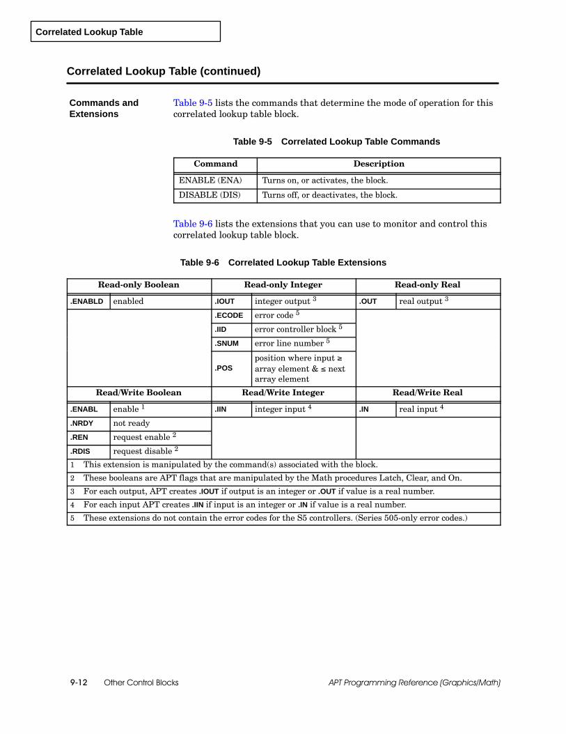
Correlated Lookup Table
Other Control Blocks9-12 APT Programming Reference (Graphics/Math)
Correlated Lookup Table (continued)
Table 9-5 lists the commands that determine the mode of operation for thiscorrelated lookup table block.
Table 9-5 Correlated Lookup Table Commands
Command Description
ENABLE (ENA) Turns on, or activates, the block.
DISABLE (DIS) Turns off, or deactivates, the block.
Table 9-6 lists the extensions that you can use to monitor and control thiscorrelated lookup table block.
Table 9-6 Correlated Lookup Table Extensions
Read-only Boolean Read-only Integer Read-only Real
.ENABLD enabled .IOUT integer output 3 .OUT real output 3
.ECODE error code 5
.IID error controller block 5
.SNUM error line number 5
.POSposition where input ∫array element & nextarray element
Read/Write Boolean Read/Write Integer Read/Write Real
.ENABL enable 1 .IIN integer input 4 .IN real input 4
.NRDY not ready
.REN request enable 2
.RDIS request disable 2
1 This extension is manipulated by the command(s) associated with the block.
2 These booleans are APT flags that are manipulated by the Math procedures Latch, Clear, and On.
3 For each output, APT creates .IOUT if output is an integer or .OUT if value is a real number.
4 For each input APT creates .IIN if input is an integer or .IN if value is a real number.
5 These extensions do not contain the error codes for the S5 controllers. (Series 505-only error codes.)
Commands andExtensions
Scale
Other Control Blocks 9-13APT Programming Reference (Graphics/Math)
9.5 Scale
The scale block transforms an input value to an output value by scaling thevalue between specified input and output ranges.
If the input is an integer, APT sends the appropriate value to theoutput.
If the input is a real number and the output is an analog value, APTassumes that the input is limited to the input range and automaticallyscales the output to the correct format (zero offset, 20% bias, orbipolar). If an input is outside this range, the output is set to themaximum or minimum value of the subtype.
The scale block allows you to define an input range and an output range.The block converts an input value to an output value by using the formula:
output =(input --- input low range)
(input high range --- input low range)* X + output low range
where X = output high range --- output low range
The initial values of the high and low ranges are defined in the form andstored in extension variables that can be changed from the program.
A scale block can be used to change a 0.0 to 1.0 range signal to a 1.0 to 0.0signal. For example, if you want to use the output from a block to drive areverse-acting control valve, you can use a scale block to provide the correctinversion. For reverse-acting block execution, set the values in the scaleform for the input to range from 1 to 0, and the values for the output torange from 0 to 1.
For Series 505 controllers, the analog output always ranges from 0 to 32000(zero offset), from 6400 to 32000 (20% bias), or from --32000 to +32000(bipolar). For S5 controllers, the analog output ranges are from 0 to 1024(zero offset), or from --1024 to 1024 (bipolar).
The scale block is supported for Series 505 and S5 controllers, but not forthe 560/560T controllers.
When you define a scale CFB with the form that is shown in Figure 9-5, youhave the following options:
You can use the default names that appear in the form.
You can add new names: declared variables or dot extensions fromother blocks.
Overview
Availability
BlockConfiguration

Scale
Other Control Blocks9-14 APT Programming Reference (Graphics/Math)
Scale (continued)
Name: xxxxxx Description:Input: xxxxxx.IN
Output: xxxxxx.OUT S
As the input changes from 0.0 to 1.0 .the output changes from 0.0 to 1.0 .
-- -- -- -- -- -- -- -- -- -- -- -- -- -- -- -- -- End of Form -- -- -- -- -- -- -- -- -- -- -- -- -- -- -- -- -- --
SCALE
xxxxxx.ININ
SCALExxxxxx
?F1
ESCCTLsF2
OPTsF3
IN
xxxxxx
xxxxxx
SCALE
SCALEOUT
OUTxxxxxx.OUT
Figure 9-5 Scale Form
Input: name of real or integer input (IN); default is cfb_name.IN.
Output: name of analog, real, or integer output (OUT); default is cfb_name.OUT).
As the input changes from _____ to _____. Enter the low and high input ranges;default of low input range is zero; default of high input range is one.
the output changes from _____ to _____. Enter the low and high output ranges;default of low output range is zero; default of high output range is one.

Scale
Other Control Blocks 9-15APT Programming Reference (Graphics/Math)
Table 9-7 lists the commands that determine the mode of operation for thisscale block.
Table 9-7 Scale Commands
Command Description
ENABLE (ENA) Turns on, or activates, the block.
DISABLE (DIS) Turns off, or deactivates, the block.
Table 9-8 lists the extensions that you can use to monitor and control thisscale block.
Table 9-8 Scale Extensions
Read-only Boolean Read-only Integer Read-only Real
.ENABLD enabled .IOUT integer output 3 .OUT real output 3
.ECODE error code 4
.IID error controller block 4
.SNUM error line number 4
Read/Write Boolean Read/Write Integer Read/Write Real
.ENABL enable 1 .IIN integer input 5 .IN real input 5
.NRDY not ready .HRIN input high range
.REN request enable 2 .LRIN input low range
.RDIS request disable 2 .HROUT output high range
.LROUT output low range
1 This extension is manipulated by the command(s) associated with the block.
2 These booleans are APT flags that are manipulated by the Math procedures Latch, Clear, and On.
3 For each output, APT creates .IOUT if output is an integer or .OUT if value is a real number.
4 These extensions do not contain the error codes for the S5 controllers. (Series 505-only error codes)
5 For each input, APT creates .IIN if input is an integer or .IN if value is a real number.
Commands andExtensions


Math Language Overview 10-1APT Programming Reference (Graphics/Math)
Chapter 10
Math Language Overview
10.1 Understanding the Math Language 10-2. . . . . . . . . . . . . . . . . . . . . . . . . . . . . . . . . . . . . . . . . . . . . .Math Blocks 10-2. . . . . . . . . . . . . . . . . . . . . . . . . . . . . . . . . . . . . . . . . . . . . . . . . . . . . . . . . . . . . . . . . . . .Types of Math Block Code 10-4. . . . . . . . . . . . . . . . . . . . . . . . . . . . . . . . . . . . . . . . . . . . . . . . . . . . . . . .Guidelines for Series 505 Controllers 10-5. . . . . . . . . . . . . . . . . . . . . . . . . . . . . . . . . . . . . . . . . . . . . . .Key Words Used by APT 10-6. . . . . . . . . . . . . . . . . . . . . . . . . . . . . . . . . . . . . . . . . . . . . . . . . . . . . . . . .
10.2 Identifiers 10-7. . . . . . . . . . . . . . . . . . . . . . . . . . . . . . . . . . . . . . . . . . . . . . . . . . . . . . . . . . . . . . . . . . . . .Overview 10-7. . . . . . . . . . . . . . . . . . . . . . . . . . . . . . . . . . . . . . . . . . . . . . . . . . . . . . . . . . . . . . . . . . . . . . .User-defined Identifiers 10-7. . . . . . . . . . . . . . . . . . . . . . . . . . . . . . . . . . . . . . . . . . . . . . . . . . . . . . . . . .System-defined Extensions 10-8. . . . . . . . . . . . . . . . . . . . . . . . . . . . . . . . . . . . . . . . . . . . . . . . . . . . . . .User-defined Extensions 10-8. . . . . . . . . . . . . . . . . . . . . . . . . . . . . . . . . . . . . . . . . . . . . . . . . . . . . . . . .
10.3 Direct Memory Addressing 10-9. . . . . . . . . . . . . . . . . . . . . . . . . . . . . . . . . . . . . . . . . . . . . . . . . . . . . .Overview 10-9. . . . . . . . . . . . . . . . . . . . . . . . . . . . . . . . . . . . . . . . . . . . . . . . . . . . . . . . . . . . . . . . . . . . . . .
10.4 Data Types and Arithmetic Operations 10-10. . . . . . . . . . . . . . . . . . . . . . . . . . . . . . . . . . . . . . . . . . .Overview 10-10. . . . . . . . . . . . . . . . . . . . . . . . . . . . . . . . . . . . . . . . . . . . . . . . . . . . . . . . . . . . . . . . . . . . . . .Expressions 10-11. . . . . . . . . . . . . . . . . . . . . . . . . . . . . . . . . . . . . . . . . . . . . . . . . . . . . . . . . . . . . . . . . . . .Integers 10-12. . . . . . . . . . . . . . . . . . . . . . . . . . . . . . . . . . . . . . . . . . . . . . . . . . . . . . . . . . . . . . . . . . . . . . . .Real Numbers 10-13. . . . . . . . . . . . . . . . . . . . . . . . . . . . . . . . . . . . . . . . . . . . . . . . . . . . . . . . . . . . . . . . . .Boolean Values 10-14. . . . . . . . . . . . . . . . . . . . . . . . . . . . . . . . . . . . . . . . . . . . . . . . . . . . . . . . . . . . . . . . .
10.5 Math Block Structure 10-16. . . . . . . . . . . . . . . . . . . . . . . . . . . . . . . . . . . . . . . . . . . . . . . . . . . . . . . . . . .Overview 10-16. . . . . . . . . . . . . . . . . . . . . . . . . . . . . . . . . . . . . . . . . . . . . . . . . . . . . . . . . . . . . . . . . . . . . . .Code Specifier Section (Series 505 only) 10-18. . . . . . . . . . . . . . . . . . . . . . . . . . . . . . . . . . . . . . . . . . .Declaration Section 10-19. . . . . . . . . . . . . . . . . . . . . . . . . . . . . . . . . . . . . . . . . . . . . . . . . . . . . . . . . . . . . .Using a Declaration Statement 10-20. . . . . . . . . . . . . . . . . . . . . . . . . . . . . . . . . . . . . . . . . . . . . . . . . . . .Formatting a Declaration Statement 10-20. . . . . . . . . . . . . . . . . . . . . . . . . . . . . . . . . . . . . . . . . . . . . . . .Using a Locally-Declared Variable 10-22. . . . . . . . . . . . . . . . . . . . . . . . . . . . . . . . . . . . . . . . . . . . . . . . .Executable Section 10-23. . . . . . . . . . . . . . . . . . . . . . . . . . . . . . . . . . . . . . . . . . . . . . . . . . . . . . . . . . . . . .
10.6 Statements 10-24. . . . . . . . . . . . . . . . . . . . . . . . . . . . . . . . . . . . . . . . . . . . . . . . . . . . . . . . . . . . . . . . . . . .Overview 10-24. . . . . . . . . . . . . . . . . . . . . . . . . . . . . . . . . . . . . . . . . . . . . . . . . . . . . . . . . . . . . . . . . . . . . . .Comments 10-24. . . . . . . . . . . . . . . . . . . . . . . . . . . . . . . . . . . . . . . . . . . . . . . . . . . . . . . . . . . . . . . . . . . . .Assignment Statement 10-25. . . . . . . . . . . . . . . . . . . . . . . . . . . . . . . . . . . . . . . . . . . . . . . . . . . . . . . . . . .Procedure Statement 10-26. . . . . . . . . . . . . . . . . . . . . . . . . . . . . . . . . . . . . . . . . . . . . . . . . . . . . . . . . . . .Function Statement 10-26. . . . . . . . . . . . . . . . . . . . . . . . . . . . . . . . . . . . . . . . . . . . . . . . . . . . . . . . . . . . . .Command Statement 10-26. . . . . . . . . . . . . . . . . . . . . . . . . . . . . . . . . . . . . . . . . . . . . . . . . . . . . . . . . . . .Print Statement (Series 505 only) 10-26. . . . . . . . . . . . . . . . . . . . . . . . . . . . . . . . . . . . . . . . . . . . . . . . . .IF Statement 10-28. . . . . . . . . . . . . . . . . . . . . . . . . . . . . . . . . . . . . . . . . . . . . . . . . . . . . . . . . . . . . . . . . . . .WHILE Statement 10-30. . . . . . . . . . . . . . . . . . . . . . . . . . . . . . . . . . . . . . . . . . . . . . . . . . . . . . . . . . . . . . .Safety Guidelines for WHILE Loops 10-31. . . . . . . . . . . . . . . . . . . . . . . . . . . . . . . . . . . . . . . . . . . . . . . .Special SFC Considerations 10-31. . . . . . . . . . . . . . . . . . . . . . . . . . . . . . . . . . . . . . . . . . . . . . . . . . . . . .Special CFB Considerations 10-32. . . . . . . . . . . . . . . . . . . . . . . . . . . . . . . . . . . . . . . . . . . . . . . . . . . . . .
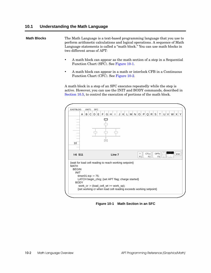
Math Language Overview10-2 APT Programming Reference (Graphics/Math)
10.1 Understanding the Math Language
The Math Language is a text-based programming language that you use toperform arithmetic calculations and logical operations. A sequence of MathLanguage statements is called a “math block.” You can use math blocks intwo different areas of APT:
A math block can appear as the math section of a step in a SequentialFunction Chart (SFC). See Figure 10-1.
A math block can appear in a math or interlock CFB in a ContinuousFunction Chart (CFC). See Figure 10-2.
A math block in a step of an SFC executes repeatedly while the step isactive. However, you can use the INIT and BODY commands, described inSection 10.5, to control the execution of portions of the math block.
10
A B C D E F G H I J K L M N O P Q R S
UNIT1 SFCEASTBLDG
OPTsF3
?F1
CTLsF2
I-6 S11 Line 7
T U
{wait for load cell reading to reach working setpoint}MATH
BEGININIT
timer01.tcp := 75;LATCH begin_chrg; {set APT flag; charge started}
BODYwork_cr := (load_cell_wt >= work_sp);
{set working cr when load cell reading exceeds working setpoint}
V W X Y
ESC
Figure 10-1 Math Section in an SFC
Math Blocks
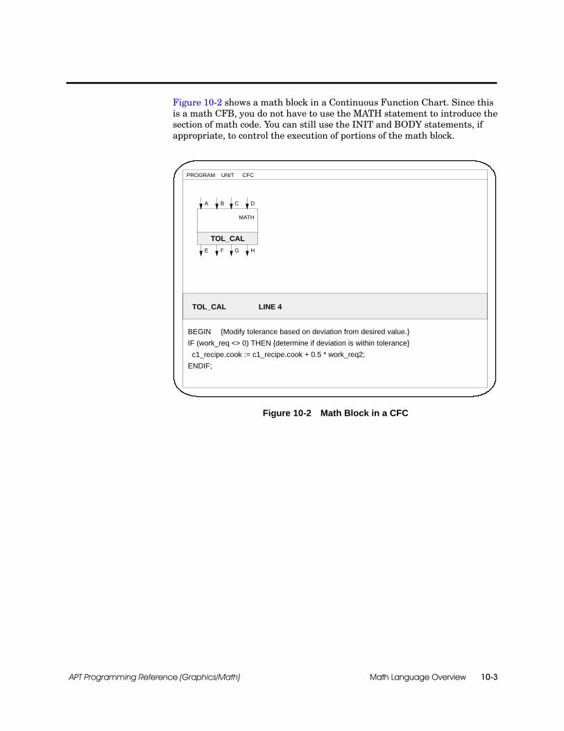
Math Language Overview 10-3APT Programming Reference (Graphics/Math)
Figure 10-2 shows a math block in a Continuous Function Chart. Since thisis a math CFB, you do not have to use the MATH statement to introduce thesection of math code. You can still use the INIT and BODY statements, ifappropriate, to control the execution of portions of the math block.
UNIT CFCPROGRAM
TOL_CAL LINE 4
BEGIN {Modify tolerance based on deviation from desired value.}
IF (work_req <> 0) THEN {determine if deviation is within tolerance}
c1_recipe.cook := c1_recipe.cook + 0.5 * work_req2;
ENDIF;
A
TOL_CAL
MATH
B C D
E F G H
Figure 10-2 Math Block in a CFC
Math Language Overview10-4 APT Programming Reference (Graphics/Math)
Understanding the Math Language (continued)
For S5 controllers, APT compiles all math blocks into STL (Statement List)code. However, for Series 505 controllers, math blocks can be compiled intoeither RLL (Relay Ladder Logic) code or SFPGM (Special FunctionProgram) code. Certain Math Language statements can be compiled onlyinto RLL code; other statements can be compiled only into SFPGM code; andsome are non-exclusive and can be compiled into either type of code.
For Series 505 controllers, the Special Functions processor executesfloating-point math calculations using SFPGM code, while RLL is executedseparately. The 560/560T controllers do not have SFPGM code andconsequently cannot perform SFPGM-type operations.
Although S5 controllers do not use SFPGM code, they do have SFPGMfunctionality; they perform both floating-point math and RLL calculationsin STL in the cyclic scan.
If you have a Series 505 controller, bear in mind that you cannot mixRLL-only statements and SFPGM-only statements in the same math block.For example, a math block that contains an RLL-only statement cannot alsocontain an SFPGM-only statement. You can include non-exclusivestatements in any math block. Use the PRAGMA statement, described laterin this chapter, when you intend a math block to be only RLL or onlySFPGM code. Table 11-1 and Table 11-2 in Chapter 11 list the mathprocedures and functions and identify whether they are for RLL only,SFPGM only, or both.
Types of MathBlock Code

Math Language Overview 10-5APT Programming Reference (Graphics/Math)
RLL code executes faster than SFPGM code; therefore, if you need to ensurethe fastest possible execution, follow these conventions in writing mathblocks for a Series 505 controller:
Avoid functions and procedures that are SFPGM only.
Avoid variables or expressions in integer or real arrays unless thecontroller release supports this in RLL: see the table on “APT FeaturesSupported by Series 505 Controller Models” in the “APT Overview”chapter of the SIMATIC APT Programming Reference (Tables) Manual.The following are examples of each.
array1[pointer]array7[ptr + 1]
Use boolean values and integers in expressions. The following generateRLL code.
bool1 OR bool2;int1 := 10 + int2;
Avoid arithmetic operations and expressions with real values. Thefollowing generate SFPGM code and should be avoided.
real1 > 2.0 * real2;real1 := real2 * 2.0;
Use real values only in relational operations and in simpleassignments. The following generate RLL code.
real1 > 2.0;real1 := real2;real1 := 0.0;
Avoid the use of temporary variables, which are explained inSection 10.3.
Guidelines forSeries 505Controllers

Math Language Overview10-6 APT Programming Reference (Graphics/Math)
Understanding the Math Language (continued)
The Math Language described in this chapter includes key words APTdefines for one and only one purpose.
Data types are declared in a math block by using key words such asBOOLEAN, INTEGER, REAL.
Delimiters indicate sections of a math block with key words, such asBEGIN, INIT, BODY. The key word MATH marks the beginning of themath section in an SFC step.
Conditional statements use the following types of key words: IF,THEN, ELSE, ELSIF, ENDIF.
Math Language functions perform a wide range of arithmetic (realand integer), trigonometric, and boolean operations. The key wordsdefined by APT to identify these functions are listed in Table 11-2.
Math Language procedures perform specific tasks as defined byAPT. The key words defined by APT to identify these procedures arelisted in Table 11-1.
In the Math Language examples, key words appear in uppercase letters.
Key Words Used byAPT

Math Language Overview 10-7APT Programming Reference (Graphics/Math)
10.2 Identifiers
APT provides three basic types of identifiers.
User-defined identifiers that you create in one of the DefinitionTables or inside a math block.
System-defined extensions that APT uses to access specific memorylocations.
User-defined extensions that you create in a recipe.
You can enter identifiers in any combination of uppercase and lowercaseletters. APT recognizes these as the same word or variable regardless of thecase.
When you name a program, unit, SFC, or CFC, you are creating auser-defined identifier. Identifiers that you use in a math block are createdin one of the following ways:
You can use the Declaration Editor to declare APT flags, constants,variables, arrays, timers, and counters that you want to have availableat the program or unit level.
You can use the I/O Symbolic Name Table, Device Definition Table,Recipe Usage Table, and Continuous Function Chart (CFC) Editor toname objects in APT.
You can use the Math Language declaration commands (BOOLEAN,REAL, INTEGER, TIMER, and ARRAY) to declare constants andvariables that can be accessed only within the math block.
In the Math language examples in this manual, user-defined identifiersappear in lowercase letters.
NOTE: Although it is not necessary to declare a variable or a constantbefore you use it in a math block, you must declare all user-definedidentifiers before you compile a program.
Overview
User-definedIdentifiers
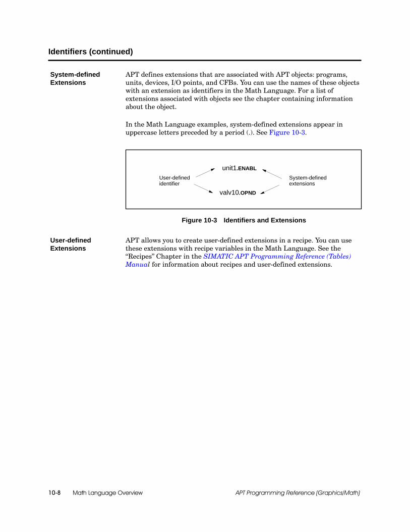
Math Language Overview10-8 APT Programming Reference (Graphics/Math)
Identifiers (continued)
APT defines extensions that are associated with APT objects: programs,units, devices, I/O points, and CFBs. You can use the names of these objectswith an extension as identifiers in the Math Language. For a list ofextensions associated with objects see the chapter containing informationabout the object.
In the Math Language examples, system-defined extensions appear inuppercase letters preceded by a period (.). See Figure 10-3.
unit1.ENABL
System-definedextensions
User-definedidentifier
valv10.OPND
Figure 10-3 Identifiers and Extensions
APT allows you to create user-defined extensions in a recipe. You can usethese extensions with recipe variables in the Math Language. See the“Recipes” Chapter in the SIMATIC APT Programming Reference (Tables)Manual for information about recipes and user-defined extensions.
System-definedExtensions
User-definedExtensions

Math Language Overview 10-9APT Programming Reference (Graphics/Math)
10.3 Direct Memory Addressing
APT allows you to access memory addresses directly by using a percent sign(%) prefix. The types of direct memory addressing available depend on thekind of controller you have.
Reserved memory (S5 and Series 505) Allows you to use memorylocations that you reserve before compiling the program.
Status word memory (Series 505 only) Allows you to read statuswords that contain operational information about your Series 505controller.
System Data Area (RS) memory (S5 only) Allows you to read theinternal system parameters that contain operational information aboutyour S5 controller.
Temporary (SFPGM) memory variables (Series 505 only) Allowyou to use memory space only while a math block is executing.
Series 505 controllers can use direct memory addresses in the Mathlanguage. S5 controllers cannot, except in the IN_ASM math statements,which are described in Appendix C, “Inline Assembly Code.” See Appendix Bof this manual for a discussion of how direct memory addressing works inAPT for Series 505 and S5 controllers.
Instead of referencing a direct address, consider making a declaration (“APTDeclarations” chapter, SIMATIC APT Programming Reference (Tables)Manual) and marking the User Assigned Address option.
Overview
Math Language Overview10-10 APT Programming Reference (Graphics/Math)
10.4 Data Types and Arithmetic Operations
The Math Language is a “strongly typed” language; that is, you mustdeclare the type of each constant and variable in the program. The followingare valid numeric data types in the Math Language: INTEGER, REAL(floating point), and BOOLEAN. See the “APT Declarations” chapter in theSIMATIC APT Programming Reference (Tables) Manual for an explanationof the naming conventions for constants and variables.
The procedures and functions described in this chapter accept only certaintypes of values as parameters; specifying a value with an invalid typecauses an error.
Overview
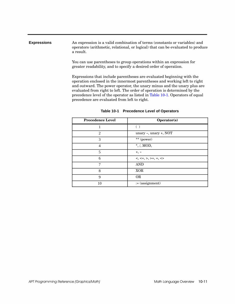
Math Language Overview 10-11APT Programming Reference (Graphics/Math)
An expression is a valid combination of terms (constants or variables) andoperators (arithmetic, relational, or logical) that can be evaluated to producea result.
You can use parentheses to group operations within an expression forgreater readability, and to specify a desired order of operation.
Expressions that include parentheses are evaluated beginning with theoperation enclosed in the innermost parentheses and working left to rightand outward. The power operator, the unary minus and the unary plus areevaluated from right to left. The order of operation is determined by theprecedence level of the operator as listed in Table 10-1. Operators of equalprecedence are evaluated from left to right.
Table 10-1 Precedence Level of Operators
Precedence Level Operator(s)
1 ( )
2 unary --, unary +, NOT
3 ** (power)
4 *, /, MOD,
5 +, --
6 <, <=, >, >=, =, <>
7 AND
8 XOR
9 OR
10 := (assignment)
Expressions

Math Language Overview10-12 APT Programming Reference (Graphics/Math)
Data Types and Arithmetic Operations (continued)
An integer is composed of one or more digits (0--9). An integer cannotcontain a decimal point. The valid range for an integer is --32768 to 32767.Integers can be expressed in any of the following ways:
An integer value with no decimal point: 29994
A binary (base 2) value preceded by the base number enclosed in poundsigns (#): #2#101 (1012=5)
A hexadecimal (base 16) value preceded by the base number enclosed inpound signs (#): #16#752A (752A16) = 29994
Arithmetic expressions using integers produce a numeric result that is alsoan integer. All values in the expression must be integers.
The integer operators available in APT are listed in Table 10-2.
Table 10-2 Integer Operators
Operator Operation PrecedenceLevel Example Numeric
Result
* Multiplication 4 4 * 6 24
/ Division 1 4 3 / 2 1
MOD Modulo 4 27 MOD 12 3
+ Addition 5 4 + 6 10
-- Subtraction 5 4 -- 6 --2
AND Logical AND 7 #2#1100 AND #2#0101 01002
XOR Exclusive OR 8 #2#1100 XOR #2#0101 10012
OR Logical OR 9 #2#1100 OR #2#0101 11012
1 Division with integers results in a truncated value.
NOTE: All integer math uses 16-bit words with 16-bit word intermediateresults, regardless of whether you have a Series 505 or an S5 controller.
Integers

Math Language Overview 10-13APT Programming Reference (Graphics/Math)
A real (floating point) number is a numeric value that includes a decimalpoint and is raised to a specified power of 10.
The valid range for a real number is dependent on controller type. For aSeries 505, the range is --9.223372 E+18 to +9.223372 E+18, and any valueexcept 0.0 that falls between --2.710501 E--20 and +5.421011 E--20 generatesa controller error. For an S5 controller, the valid range is --1.701412E+38 to+1.701412E+38, and any value except 0.0 that falls between --1.469368E--39
to +1.469368E--39 generates a controller error.
A real number can be expressed in any of four ways but must alwaysinclude a decimal point; it does not need to include the fractional portion. Ifthe sign is omitted, it is assumed to be a positive sign (+).
A value with a decimal point and the fractional portion followed by theletter E and an exponent: 12.0E--3 (12.0 ⌠ 10--3)
A value with a decimal point followed by the letter E and an exponent:12.E--3 (12.0 ⌠ 10--3)
A value with a decimal point and the fractional portion: 12.0
A value with a decimal point: 12.
Arithmetic expressions using real numbers produce a numeric result that isalso real. All values in the expression must be real numbers.
Table 10-3 lists the operators available in APT to be used with realnumbers; they are supported by all controllers except the 560/560Tcontrollers.
Table 10-3 Real Operators
Operator Operation PrecedenceLevel Example Numeric
Result
** Power 3 6.5 ** 2.0 42.25
* Multiplication 4 4. * 6. 24.
/ Division 4 3.0 / 2.0 1.5
+ Addition 5 6.5 + 8. 14.5
-- Subtraction 5 6.5 -- 8.0 --1.5
Real Numbers
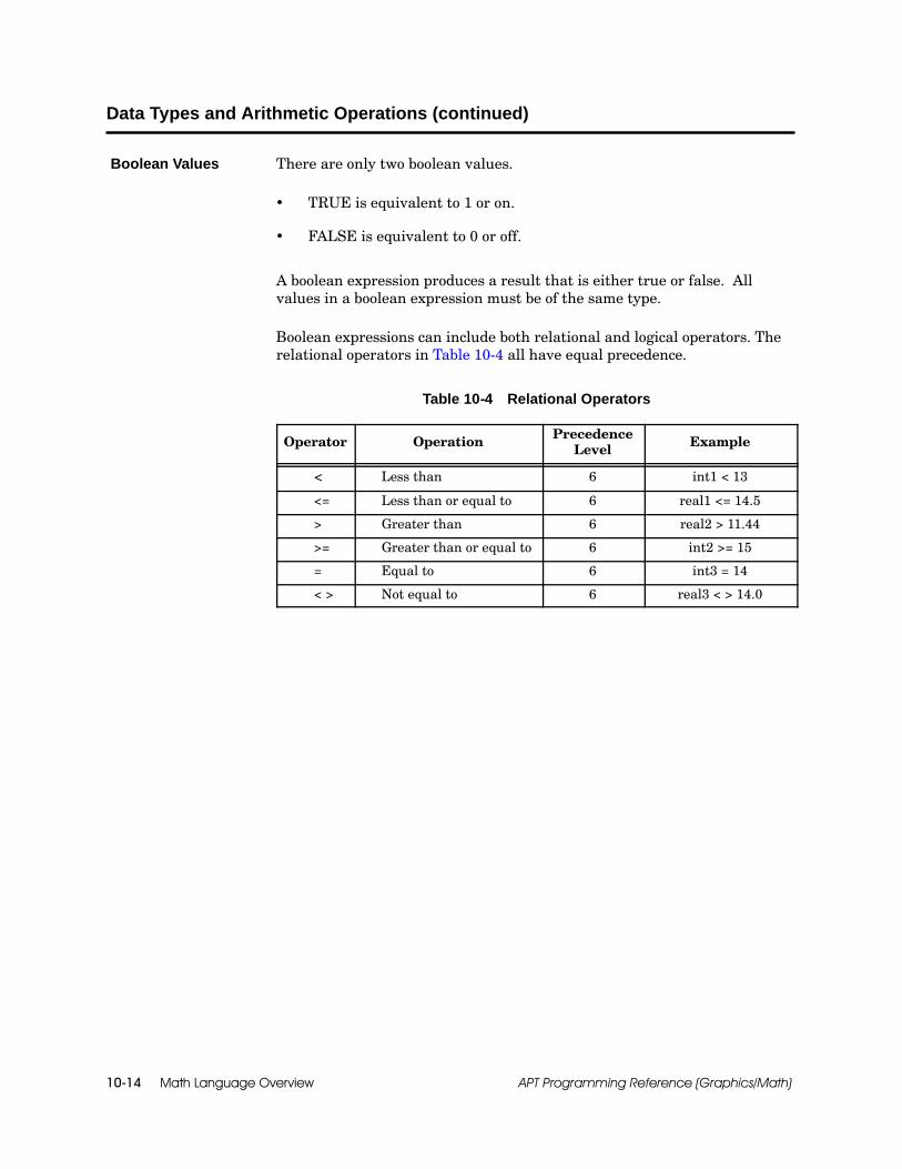
Math Language Overview10-14 APT Programming Reference (Graphics/Math)
Data Types and Arithmetic Operations (continued)
There are only two boolean values.
TRUE is equivalent to 1 or on.
FALSE is equivalent to 0 or off.
A boolean expression produces a result that is either true or false. Allvalues in a boolean expression must be of the same type.
Boolean expressions can include both relational and logical operators. Therelational operators in Table 10-4 all have equal precedence.
Table 10-4 Relational Operators
Operator Operation PrecedenceLevel Example
< Less than 6 int1 < 13
<= Less than or equal to 6 real1 <= 14.5
> Greater than 6 real2 > 11.44
>= Greater than or equal to 6 int2 >= 15
= Equal to 6 int3 = 14
< > Not equal to 6 real3 < > 14.0
Boolean Values

Math Language Overview 10-15APT Programming Reference (Graphics/Math)
The logical operators are listed in Table 10-5. Expressions used with thelogical operators must be enclosed in parentheses as shown in the examples.
Table 10-5 Logical Operators
Operator PrecedenceLevel Example Evaluates to
True if
NOT 2 NOT mcv_1.OPNDNOT (X=2)
term is Falseterm is False
AND 4 mcv_1.CLSD AND mcv_2.CLSD all terms areTrue
OR 5 mcv_3.OPND OR (pt101 < 14.9) any term isTrue
Math Language Overview10-16 APT Programming Reference (Graphics/Math)
10.5 Math Block Structure
A math block consists of a code specifier section, a declaration section, andan executable section. The code specifier and declaration sections areoptional.
The word MATH marks the beginning of the math section in an SFCstep. The key word MATH is not used in a CFB math block or asubroutine.
For Series 505 controllers, you can use the optional code specifiersection to indicate certain controller-dependent information about howyour math block compiles. The word PRAGMA indicates the beginningof this section.
If you have a declaration section, each statement begins with one of thefollowing terms: BOOLEAN, INTEGER, REAL, TIMER, or ARRAY.
The word BEGIN marks the end of the declaration section and thebeginning of the executable section in the math block. The onlystatements that can precede a BEGIN statement are declarationstatements and the code specifier section.
The executable section of a math block can contain an initializationportion and a body portion:
When a math block has both an initialization section and a bodyportion, use the INIT and BODY statements to delineate the twosections of code.
When a math block has an initialization portion, but no body portion,do not use the BODY statement.
When a math block has a body portion, but no initialization portion, donot use either the INIT or the BODY statements.
Overview
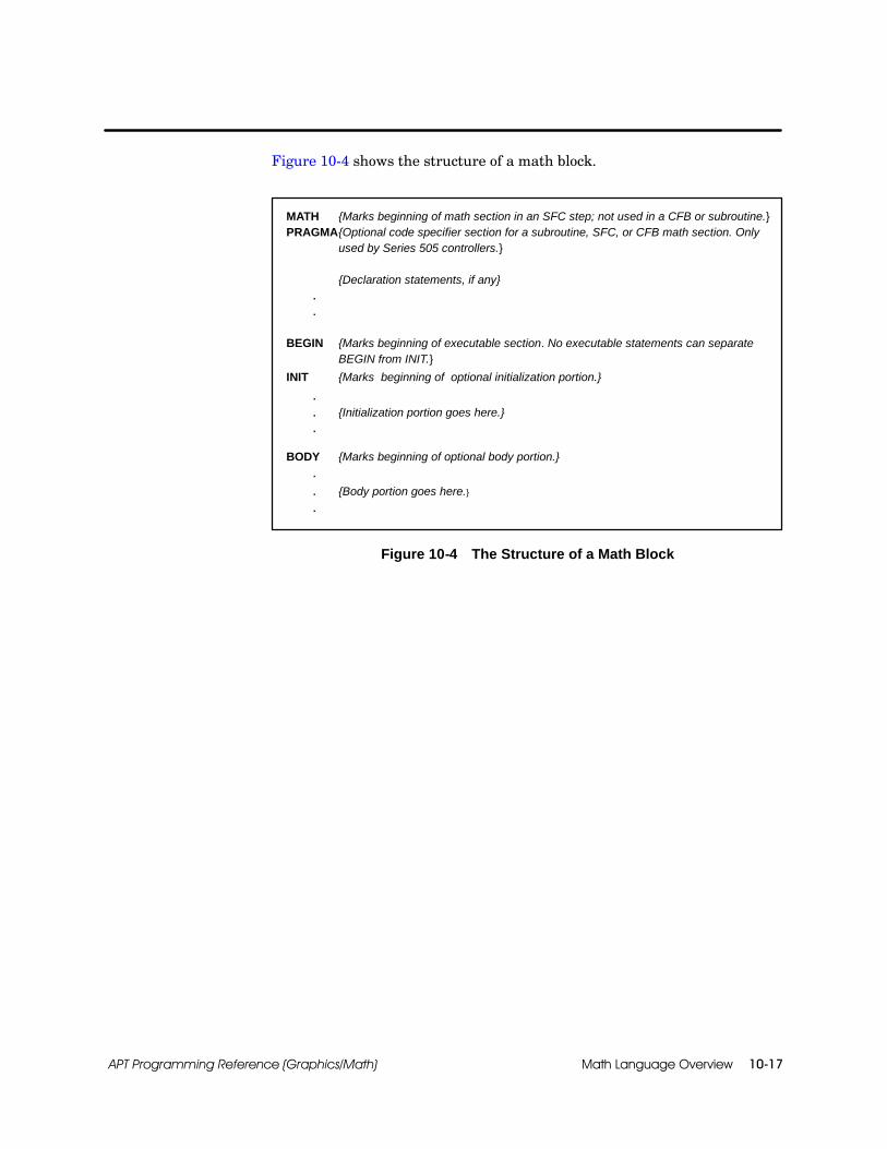
Math Language Overview 10-17APT Programming Reference (Graphics/Math)
Figure 10-4 shows the structure of a math block.
MATH {Marks beginning of math section in an SFC step; not used in a CFB or subroutine.}PRAGMA{Optional code specifier section for a subroutine, SFC, or CFB math section. Only
used by Series 505 controllers.}
{Declaration statements, if any}..
BEGIN {Marks beginning of executable section. No executable statements can separateBEGIN from INIT.}
INIT {Marks beginning of optional initialization portion.}
.
. {Initialization portion goes here.}
.
BODY {Marks beginning of optional body portion.}.. {Body portion goes here.}.
Figure 10-4 The Structure of a Math Block

Math Language Overview10-18 APT Programming Reference (Graphics/Math)
Math Block Structure (continued)
The code specifier section of a math block is an optional section that beginswith the word PRAGMA. S5 controllers do not use the PRAGMA statement.
For a Series 505 controller, you can use PRAGMA to specify whether youwant the math to be compiled exclusively in either RLL, RLL cyclic, RLLinterrupt, or SFPGM code. The use of the PRAGMA statement does notforce the type of compile; you must still follow the conventions described onpage 10-4 to determine how the code is actually compiled. However, to alertyou, PRAGMA causes a compile error to be generated if you inadvertentlyuse SFPGM code in math that you intend to be RLL only, or vice versa.
If you use PRAGMA for a Series 505 controller, the code specifier sectionmust precede the declaration section for subroutines, SFC or CFB mathsections (Figure 10-4).
Use the following format for the PRAGMA statement:
PRAGMA <type> ;
The type can be RLL, SF, RLL_CYCLIC, or RLL_INTERRUPT. The types aredescribed in Table 10-6.
Table 10-6 Controller-Dependent Code Specifications
Controller Type Meaning
Series 505 RLL Code goes in main RLL section.
Series 505 SF Code goes in SFPGM section.
Series 505 RLL_CYCLIC *Code goes in cyclic RLL section; theCompiler Control File has a field for cyclicscan rate.
Series 505 RLL_INTERRUPT * Code goes in interrupt RLL section; specialmodules can generate that interrupt.
* Neither RLL cyclic nor RLL interrupt math sections support APT flag procedures(ON, LATCH, CLEAR) or object commands (Open, Start . . .).
Code SpecifierSection(Series 505 only)
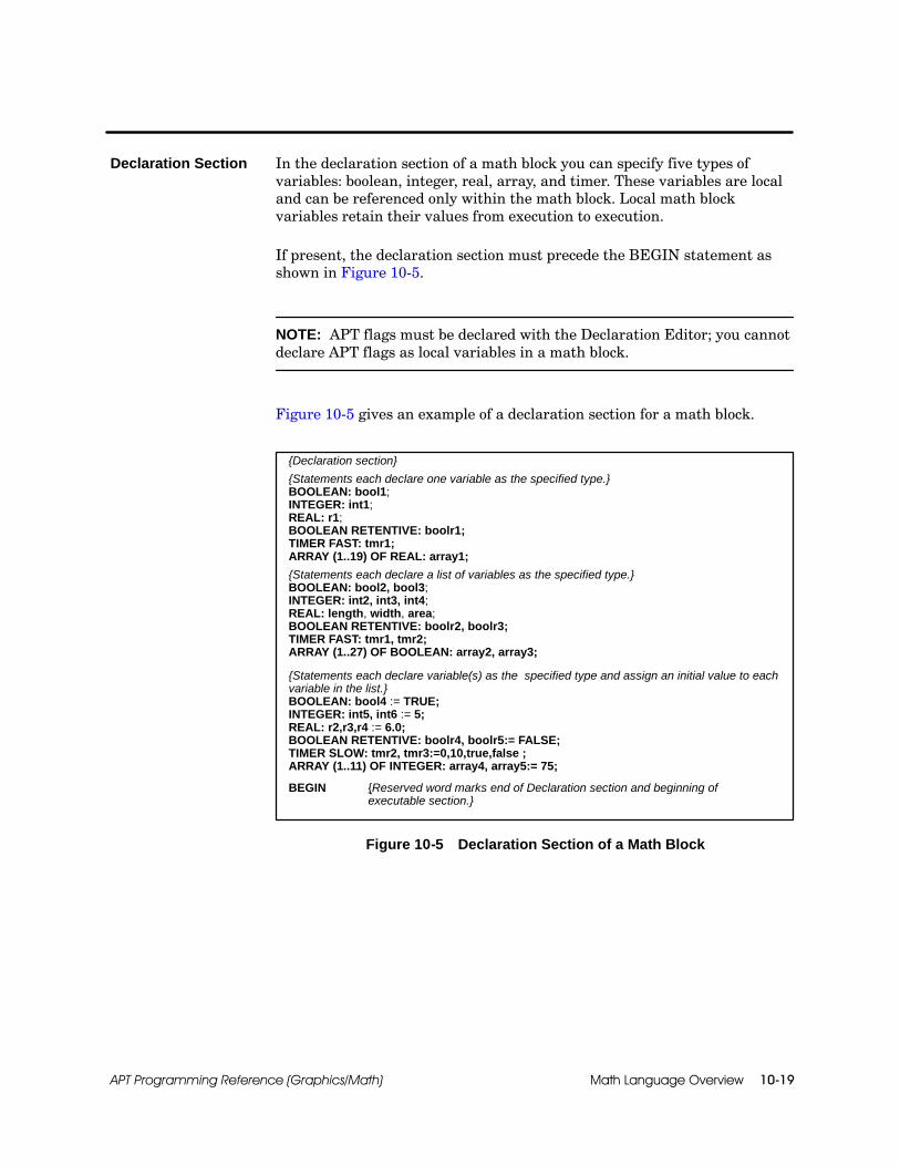
Math Language Overview 10-19APT Programming Reference (Graphics/Math)
In the declaration section of a math block you can specify five types ofvariables: boolean, integer, real, array, and timer. These variables are localand can be referenced only within the math block. Local math blockvariables retain their values from execution to execution.
If present, the declaration section must precede the BEGIN statement asshown in Figure 10-5.
NOTE: APT flags must be declared with the Declaration Editor; you cannotdeclare APT flags as local variables in a math block.
Figure 10-5 gives an example of a declaration section for a math block.
{Declaration section}
{Statements each declare one variable as the specified type.}BOOLEAN: bool1;INTEGER: int1;REAL: r1;BOOLEAN RETENTIVE: boolr1;TIMER FAST: tmr1;ARRAY (1..19) OF REAL: array1;
{Statements each declare a list of variables as the specified type.}BOOLEAN: bool2, bool3;INTEGER: int2, int3, int4;REAL: length, width, area;BOOLEAN RETENTIVE: boolr2, boolr3;TIMER FAST: tmr1, tmr2;ARRAY (1..27) OF BOOLEAN: array2, array3;
{Statements each declare variable(s) as the specified type and assign an initial value to eachvariable in the list.}BOOLEAN: bool4 := TRUE;INTEGER: int5, int6 := 5;REAL: r2,r3,r4 := 6.0;BOOLEAN RETENTIVE: boolr4, boolr5:= FALSE;TIMER SLOW: tmr2, tmr3:=0,10,true,false ;ARRAY (1..11) OF INTEGER: array4, array5:= 75;
BEGIN {Reserved word marks end of Declaration section and beginning ofexecutable section.}
Figure 10-5 Declaration Section of a Math Block
Declaration Section
Math Language Overview10-20 APT Programming Reference (Graphics/Math)
Math Block Structure (continued)
Declaration statements obey the following rules.
Each declaration statement consists of a reserved word that indicatesthe type: boolean, integer, real, timer, or array.
A colon ( : ) separates the type from the variable name(s).
The maximum number of characters in a variable name is 12. Commasseparate the variable names if you are assigning more than onevariable to the same type.
The optional portion of the declaration statement allows you to assignan initial value to the variable(s). The assigned value(s) must be in theform of a literal value, e.g., 5, 6.6, true. This value(s) is assigned to eachvariable in the declaration line. If variables require different initialvalues, use a different declaration line for each variable. If you need toinitialize a timer you must supply values for all four constants.
The following examples illustrate how to format a declaration statement fora variable, timer variable, or array.
To declare boolean, integer, and real variables, follow this format. Substituteboolean, integer, or real for type.
<type> : variable, variable,... := constant ;
All booleans are retentive for S5 controllers. You do not need to specify“retentive.” However, for Series 505 controllers, booleans can be eitherretentive or non-retentive, and so if you do not specify that a boolean isretentive, it will be treated as non-retentive. To indicate a retentiveboolean for Series 505, use this format.
boolean retentive : variable, variable,... := constant ;
Using a DeclarationStatement
Formatting aDeclarationStatement

Math Language Overview 10-21APT Programming Reference (Graphics/Math)
For a timer variable, use this format. For Series 505 controllers, substitutefast or slow for type. For S5 controllers, the only type available is slow.
timer <type>: variable, variable,...:= constant1, constant2, constant3, constant4 ;
Constant1 is an integer and contains the current value of the timer.Constant2 is an integer and contains the preset value of the timer.Constant3 is a boolean that enables the timer.Constant4 is a boolean that resets the timer.
The math timer variable is similar to the declaration timer, describedin the “APT Declarations” chapter of the APT Programming ReferenceManual (Tables). However, the math timer variable does not supportthe DELAY command. Five extensions are associated with the mathtimer variable: .TCC, .TCP, .ENABL, .RESET, and .TOUT.
NOTE: If you have an S5 controller, you cannot locally declare a fast timerin the declaration section of a block. However, you can declare both fast andslow timers for S5 when you use the Declaration Table.
For an array, use this format. The array type can be real, integer, orboolean.
array ( 1..n ) of <type>: variable, variable,...:= constant;
To specify array size, substitute a positive integer for n.For Series 505 controllers, n can be any value in the range 1--32767.For S5 controllers, the maximum number of elements depends on thearray type. An integer array can have size 1--256; a real array can havesize 1--128; and a boolean array can have size 1--4096.
If you assign a constant to the declaration, all elements in the array areset to the same value.
NOTE: For Series 505 controllers, the boolean type indicates anon-retentive array; use the array type boolean retentive for a retentivearray.

Math Language Overview10-22 APT Programming Reference (Graphics/Math)
Math Block Structure (continued)
Variables can be declared in two ways. They can be declared in the programor unit declaration table, or they can be declared within the declarationsection of a math block. Variables that are declared from within a mathblock are considered locally-declared variables.
In order to monitor a locally-declared variable while you are executingDebug or MAITT, you need to use the following formats to designate thevariable.
For locally-declared variables in a math CFB, use this format.
CFB_name.NNL.Local_Variable <.timer_extension>
For example, use the name FILL.NNL.TNK_LEVEL to view alocally-declared variable named TNK_LEVEL in a CFB named FILL.
For locally-declared variables in an SFC step, use this format. Substitutethe appropriate step number for x.
$SFC_name.SMATHx.Local_Variable <.timer_extension>
For example, use the name $CLN.SMATH3.BRU1 to view alocally-declared variable named BRU1 in Step #3 of an SFC namedCLN.
! WARNINGLocally-declared variables in an SFC step contain the step number as part ofthe variable name. Resequencing the SFC may change the step number of thelocally declared variable.
Resequencing an SFC that contains locally-declared variables could cause yourapplication to operate in an unpredictable manner, or fail in an unsafe condition,resulting in death or serious injury to personnel, and/or damage to equipment.
If you use locally declared variables, do not resequence the SFC.
Follow these guidelines for using commands with locally-declared variables.
Do not use the INC and DEC commands with locally-declared integers.
Do not use the DELAY command with locally-declared timers.
Using aLocally-DeclaredVariable

Math Language Overview 10-23APT Programming Reference (Graphics/Math)
BEGIN marks the beginning of the executable section in a math block asshown in Figure 10-6. The BEGIN statement does not end with a semicolon.
Every math block must contain one and only one BEGIN statement. Theonly statements in a math block that can precede the BEGIN statement arePRAGMA and the declaration statements (BOOLEAN, INTEGER, REAL,etc.).
{Optional code specifier section (Series 505 controllers only)}PRAGMA (“SF”);
{Declaration section}REAL: length, width, area;
BEGIN {Executable section}length := 10.5;width := 6.0;area := length * width;
Figure 10-6 Executable Section of a Math Block
INIT marks the beginning of the initialization portion of a math block. Thisportion executes only the first time that the math block executes. INITexecutes every time the SFC step is entered.
BODY marks the beginning of the body portion of a math block. This portiondoes not execute the first time that the block executes; however, the bodyportion executes each subsequent time that the block executes andcontinues to execute as long as the block remains active.
Figure 10-7 shows a math section with both an INIT and a BODY portion.
REAL : r1; {Declaration section}BEGIN {Marks beginning of executable section}INIT {Marks the beginning of the initialization portion}
r1 := 0.; {Executes first time only}BODY {Marks beginning of body portion}
r1 := r1 + 1.; {Executes every time except first}
Figure 10-7 The Structure of a Math Block
Executable Section

Math Language Overview10-24 APT Programming Reference (Graphics/Math)
10.6 Statements
The executable section of a math block consists of one or more statementsthat can be any of the following: a comment, an assignment statement, aprocedure statement, a print statement, or a conditional statement.
Text that is delimited by braces or by a parenthesis/asterisk combinations isa comment. A comment helps to document a program but does not affect itsexecution. For example:
{ This is a comment. }
(* This is also a comment. *)
A comment that begins with a left brace must end with a right brace; acomment that begins with a parenthesis/asterisk must end with anasterisk/parenthesis.
A statement can include a comment, or a comment can be on a separate lineby itself.
You can nest one comment within another comment if you use differentdelimiters. For example, the following comments are valid:
{This comment (*contains a*) nested comment.}(* So {does this} one *)
The following comment is not valid because both comments use braces asdelimiters:
{This comment {is not} valid.}
Overview
Comments

Math Language Overview 10-25APT Programming Reference (Graphics/Math)
The assignment operator (:=) assigns the value of the expression on theright-hand side of the statement to the identifier on the left-hand side of thestatement and has the following format.
identifier := expression;
The identifier can be the name of a variable, an array, or an array element.For Series 505 only, the identifier can also be a direct controller address.The identifier cannot be an APT flag variable or read-only variable (aconstant or field input such as AI, DI, WI, etc.).
The expression can be a single value or a complex expression that isevaluated to produce a result. In either case, the value of the expression onthe left-hand side must evaluate to the same type of value as the identifier.See the examples in Figure 10-8.
Each assignment statement must end with a semicolon (;).
{Declaration section}
BOOLEAN: bool1, bool2, bool3, bool4;INTEGER: int1, int2, int3;REAL: length, width, area;
BEGIN {Executable section}
{Boolean assignment statements}bool1 := TRUE;bool2 := (pt101 >= 101.5);
{Assigns integer value to element one of array c.}c[1] := (int1 + (int2 -- int3)) * 8;
{Assign real values to variables, length and width.}length := 10.5;width := 6.0;
{Multiplies length by width and places result in a variable named area.}area := length * width;
{Moves array b into array c.}c := b;
Figure 10-8 Using Assignment Statements
AssignmentStatement

Math Language Overview10-26 APT Programming Reference (Graphics/Math)
Statements (continued)
Procedure statements consist of a predefined word from the MathLanguage, followed by the appropriate parameters enclosed in parentheses.Use the following format for a procedure statement. Each procedurestatement must end with a semicolon ( ; ).
keyword (parameter list);
The keyword in a procedure statement is either a predefined word thatidentifies the APT procedure, or a user-defined subroutine procedure. Theparameter list depends on the procedure. Table 11-1 lists the APT procedurestatements and the types of parameter that can be used with eachstatement.
Function statements consist of a variable, an assignment operator, and apredefined word from the Math Language, followed by the appropriateparameters in parentheses. Use the following format for a functionstatement. Each function statement must end with a semicolon ( ; ).
variable := keyword (parameter list);
The keyword in a function statement is a predefined word that identifies theAPT function. The type of values that are allowed as parameters depends onthe function. Table 11-2 lists the APT function statements, the types ofvalues that can be used as parameters, and the types of math code in whichthe function can be used.
Command statements allow you to execute an action on an object eitherfrom the parallel section of an SFC or from a math block that generatesRLL or STL code. The commands that can be used with individual APTobjects are listed with the explanation of each object. For example, see the“Device Types” chapter in the APT Programming Reference (Tables) Manualfor an explanation of device commands. Use the following format for acommand statement. Each function statement must end with asemicolon ( ; ).
command object;
The PRINT statement is an SFPGM procedure that allows you to send textto Port 1 on the 545, 545L (545 Lite), 555, or 575, or one or both of theoutput ports on the 565T/565P card. The PRINT statement is not availablefor 560/560T or S5 controllers.
Use the following format for a PRINT statement. Each function statementmust end with a semicolon ( ; ).
PRINT(port-number,text);
ProcedureStatement
Function Statement
CommandStatement
Print Statement(Series 505 only)
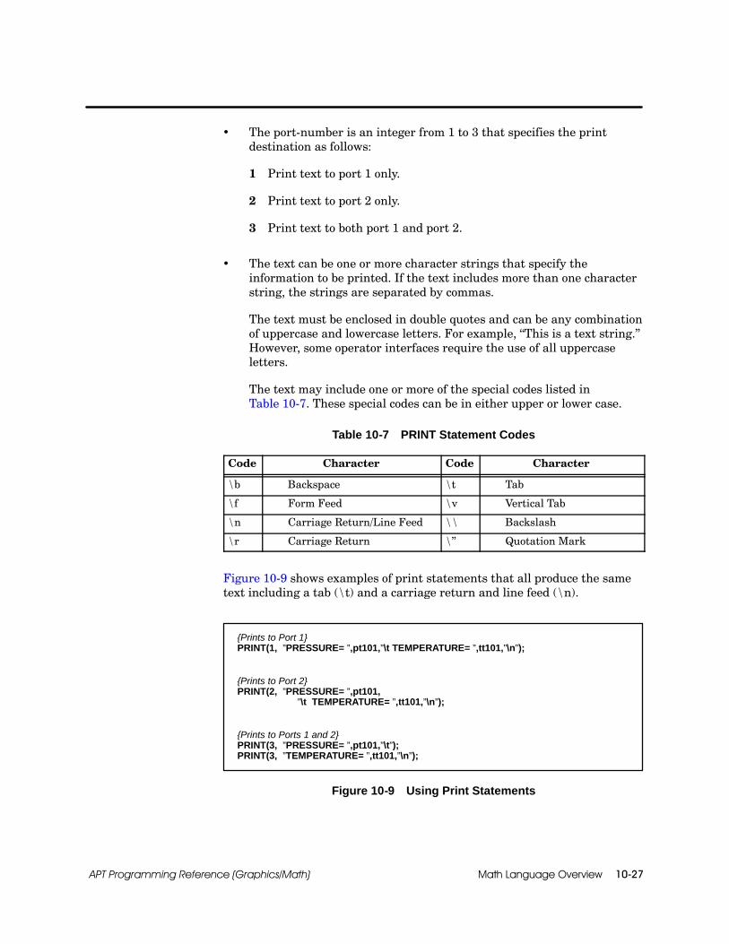
Math Language Overview 10-27APT Programming Reference (Graphics/Math)
The port-number is an integer from 1 to 3 that specifies the printdestination as follows:
1 Print text to port 1 only.
2 Print text to port 2 only.
3 Print text to both port 1 and port 2.
The text can be one or more character strings that specify theinformation to be printed. If the text includes more than one characterstring, the strings are separated by commas.
The text must be enclosed in double quotes and can be any combinationof uppercase and lowercase letters. For example, “This is a text string.”However, some operator interfaces require the use of all uppercaseletters.
The text may include one or more of the special codes listed inTable 10-7. These special codes can be in either upper or lower case.
Table 10-7 PRINT Statement Codes
Code Character Code Character
\b Backspace \t Tab
\f Form Feed \v Vertical Tab
\n Carriage Return/Line Feed \\ Backslash
\r Carriage Return \” Quotation Mark
Figure 10-9 shows examples of print statements that all produce the sametext including a tab (\t) and a carriage return and line feed (\n).
{Prints to Port 1}PRINT(1, ”PRESSURE= ”,pt101,”\t TEMPERATURE= ”,tt101,”\n”);
{Prints to Port 2}PRINT(2, ”PRESSURE= ”,pt101,
”\t TEMPERATURE= ”,tt101,”\n”);
{Prints to Ports 1 and 2}PRINT(3, ”PRESSURE= ”,pt101,”\t”);PRINT(3, ”TEMPERATURE= ”,tt101,”\n”);
Figure 10-9 Using Print Statements
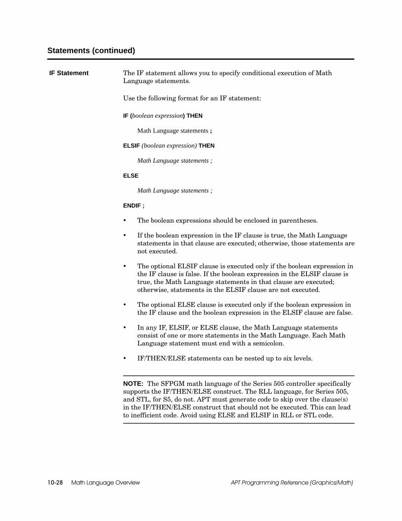
Math Language Overview10-28 APT Programming Reference (Graphics/Math)
Statements (continued)
The IF statement allows you to specify conditional execution of MathLanguage statements.
Use the following format for an IF statement:
IF (boolean expression) THEN
Math Language statements ;
ELSIF (boolean expression) THEN
Math Language statements ;
ELSE
Math Language statements ;
ENDIF ;
The boolean expressions should be enclosed in parentheses.
If the boolean expression in the IF clause is true, the Math Languagestatements in that clause are executed; otherwise, those statements arenot executed.
The optional ELSIF clause is executed only if the boolean expression inthe IF clause is false. If the boolean expression in the ELSIF clause istrue, the Math Language statements in that clause are executed;otherwise, statements in the ELSIF clause are not executed.
The optional ELSE clause is executed only if the boolean expression inthe IF clause and the boolean expression in the ELSIF clause are false.
In any IF, ELSIF, or ELSE clause, the Math Language statementsconsist of one or more statements in the Math Language. Each MathLanguage statement must end with a semicolon.
IF/THEN/ELSE statements can be nested up to six levels.
NOTE: The SFPGM math language of the Series 505 controller specificallysupports the IF/THEN/ELSE construct. The RLL language, for Series 505,and STL, for S5, do not. APT must generate code to skip over the clause(s)in the IF/THEN/ELSE construct that should not be executed. This can leadto inefficient code. Avoid using ELSE and ELSIF in RLL or STL code.
IF Statement

Math Language Overview 10-29APT Programming Reference (Graphics/Math)
Figure 10-10 shows several examples of the IF statement. In the fifthexample section, the direct addresses used are for Series 505 controllers. Foran S5 controller, direct addresses in the Math language are not allowed.
IF (chrg_path = 1) THENchrg_sp := wpw1.c_setpoint + tare_wt;
ENDIF;
IF (chrg_path = 1) THENchrg_sp := wpw1.c_setpoint + tare_wt;
ELSEchrg_sp :=wpw1.d_setpoint + tare_wt;
ENDIF;
IF (chrg_path = 1) THENchrg_sp := wpw1.c_setpoint + tare_wt;
ELSIF (chrg_path = 2) THENchrg_sp := wpw1.d_setpoint + tare_wt;
ELSEchrg_sp :=wpw1.e_setpoint + tare_wt;
ENDIF;
IF (chrg_path = 1) THENchrg_sp := wpw1.c_setpoint + tare_wt;
ELSIF (chrg_path = 2) THENchrg_sp := wpw1.d_setpoint + tare_wt;
ELSIF (chrg_path = 3) THENchrg_sp := wpw1.e_setpoint + tare_wt;
ELSEchrg_sp :=wpw1.f_setpoint + tare_wt;
ENDIF;
IF ((%V8. <= %V10.) OR (%V12. > 0.0)) THEN {Only Series 505 controllers}charg_path := 1; {can use direct addresses}
ELSE {in Math language.}charg_path := 0;
ENDIF;
IF (B1) THENwork_req := 2;
ELSEwork_req := 1;
ENDIF;
Figure 10-10 Using IF Statements

Math Language Overview10-30 APT Programming Reference (Graphics/Math)
Statements (continued)
The WHILE statement allows you to program the multiple execution ofmath statements according to a specific condition. The WHILE statementcan be used with S5 controllers and with the following Series 505controllers: the 545, 545L, 555, 565/565T/565P, and 575 controllers. ForSeries 505 controllers, the WHILE statement is an SFPGM-only statement.
Use the following format for the WHILE statement. Enclose the booleanexpression in parentheses.
WHILE (boolean expression) LOOP
Math Language statements ;
END LOOP ;
When the step containing the WHILE is active, or the math blockcontaining the WHILE is enabled, the WHILE statement acts as follows.
When the boolean expression in the WHILE clause is true, all the mathlanguage statements execute in order.
The math language statements continue to execute until one of thefollowing occurs:
The boolean expression becomes false.
The step is exited (for a WHILE statement in an SFC step).
The math CFB is disabled (for a WHILE statement in a math CFB).
An example of the WHILE statement is provided in Figure 10-11. The codeshown causes the first four locations of an integer array namedFILL_ARRAY to be loaded with the value of 100.
CHK := 1;WHILE (CHK <= 4) LOOP
FILL_ARRAY[CHK] := 100;CHK := CHK + 1;
END LOOP;
Figure 10-11 Using the While Statement
WHILE Statement

Math Language Overview 10-31APT Programming Reference (Graphics/Math)
Use these safety guidelines to create code with WHILE statements:
Do not create a program in which a WHILE statement can runendlessly (that is, an endless loop). Plan the boolean conditionassociated with the WHILE carefully. In the event that an endless loopcondition does occur, deactivate the step or CFB in which the loop islocated, and exit the WHILE statement.
Initialize all variables associated with the WHILE for every executionof the loop.
Do not program a WHILE statement that runs for more than0.05 to 0.10 seconds, in order to avoid delaying the execution of otherprogram tasks, such as analog alarms, SF programs, or other loops.
Do not allow a WHILE condition that takes too long to occur.
Do not allow a WHILE time that is too long.
Do not allow many WHILE statements or iterations that require toomuch time to execute.
! WARNINGUse of the WHILE loop in APT programs can either stop program execution ordegrade controller performance.
The WHILE statement is powerful, and misuse of it could cause unpredictableoperations that could result in death or serious injury to personnel, and/ordamage to equipment.
Be sure to use the WHILE statement correctly. Follow the above SafetyGuidelines for WHILE Loops to ensure that controller performance is notadversely affected.
When you use a WHILE statement in a step, the WHILE statement isexecuted to completion before any statements below the END statement areexecuted.
You can place a WHILE statement in any part of the math section of a step,including the INIT section. A WHILE that is located in the INIT section of astep runs to completion the first time the step is executed.
Safety Guidelinesfor WHILE Loops
Special SFCConsiderations

Math Language Overview10-32 APT Programming Reference (Graphics/Math)
Statements (continued)
When you use a WHILE statement in a CFB, the WHILE statement isexecuted to completion before any statements below the END statement areexecuted.
The CFB .ENABLD bit does not turn on until all the statements in the CFBhave been executed at least once. Therefore, an extensive WHILE can causea delay between the time a CFB begins executing and the setting of the CFB.ENABLD bit.
When the math CFB containing the WHILE is sampled or is event-driven, aWHILE that has begun execution runs only as long as its associated booleancondition is true.
Special CFBConsiderations

Math Functions and Procedures 11-1APT Programming Reference (Graphics/Math)
Chapter 11
Math Functions and Procedures
11.1 Overview 11-3. . . . . . . . . . . . . . . . . . . . . . . . . . . . . . . . . . . . . . . . . . . . . . . . . . . . . . . . . . . . . . . . . . . . . .Understanding Procedures 11-3. . . . . . . . . . . . . . . . . . . . . . . . . . . . . . . . . . . . . . . . . . . . . . . . . . . . . . .Understanding Functions 11-3. . . . . . . . . . . . . . . . . . . . . . . . . . . . . . . . . . . . . . . . . . . . . . . . . . . . . . . . .Availability 11-3. . . . . . . . . . . . . . . . . . . . . . . . . . . . . . . . . . . . . . . . . . . . . . . . . . . . . . . . . . . . . . . . . . . . . .Using Functions and Procedures in Subroutines (Series 505) 11-6. . . . . . . . . . . . . . . . . . . . . . . . . .
11.2 Function and Procedure Definitions 11-7. . . . . . . . . . . . . . . . . . . . . . . . . . . . . . . . . . . . . . . . . . . . .ABS Function 11-7. . . . . . . . . . . . . . . . . . . . . . . . . . . . . . . . . . . . . . . . . . . . . . . . . . . . . . . . . . . . . . . . . . .ARCCOS Function 11-8. . . . . . . . . . . . . . . . . . . . . . . . . . . . . . . . . . . . . . . . . . . . . . . . . . . . . . . . . . . . . .ARCSIN Function 11-9. . . . . . . . . . . . . . . . . . . . . . . . . . . . . . . . . . . . . . . . . . . . . . . . . . . . . . . . . . . . . . .ARCTAN Function 11-10. . . . . . . . . . . . . . . . . . . . . . . . . . . . . . . . . . . . . . . . . . . . . . . . . . . . . . . . . . . . . . .BCDBIN Procedure 11-11. . . . . . . . . . . . . . . . . . . . . . . . . . . . . . . . . . . . . . . . . . . . . . . . . . . . . . . . . . . . . .BINBCD Procedure 11-12. . . . . . . . . . . . . . . . . . . . . . . . . . . . . . . . . . . . . . . . . . . . . . . . . . . . . . . . . . . . . .BIT_ASSIGN Procedure 11-13. . . . . . . . . . . . . . . . . . . . . . . . . . . . . . . . . . . . . . . . . . . . . . . . . . . . . . . . . .BITCLEAR Procedure 11-14. . . . . . . . . . . . . . . . . . . . . . . . . . . . . . . . . . . . . . . . . . . . . . . . . . . . . . . . . . . .BITSET Procedure 11-15. . . . . . . . . . . . . . . . . . . . . . . . . . . . . . . . . . . . . . . . . . . . . . . . . . . . . . . . . . . . . .BITS_TO_INT Function 11-16. . . . . . . . . . . . . . . . . . . . . . . . . . . . . . . . . . . . . . . . . . . . . . . . . . . . . . . . . .BITTEST Function 11-18. . . . . . . . . . . . . . . . . . . . . . . . . . . . . . . . . . . . . . . . . . . . . . . . . . . . . . . . . . . . . . .CLEAR Procedure 11-19. . . . . . . . . . . . . . . . . . . . . . . . . . . . . . . . . . . . . . . . . . . . . . . . . . . . . . . . . . . . . . .COPY_BYTES Procedure 11-20. . . . . . . . . . . . . . . . . . . . . . . . . . . . . . . . . . . . . . . . . . . . . . . . . . . . . . . .COPY_DIRECT Procedure 11-22. . . . . . . . . . . . . . . . . . . . . . . . . . . . . . . . . . . . . . . . . . . . . . . . . . . . . . .COS Function 11-24. . . . . . . . . . . . . . . . . . . . . . . . . . . . . . . . . . . . . . . . . . . . . . . . . . . . . . . . . . . . . . . . . .EDGE Function 11-25. . . . . . . . . . . . . . . . . . . . . . . . . . . . . . . . . . . . . . . . . . . . . . . . . . . . . . . . . . . . . . . . .EXP Function 11-26. . . . . . . . . . . . . . . . . . . . . . . . . . . . . . . . . . . . . . . . . . . . . . . . . . . . . . . . . . . . . . . . . . .FRS Procedure 11-27. . . . . . . . . . . . . . . . . . . . . . . . . . . . . . . . . . . . . . . . . . . . . . . . . . . . . . . . . . . . . . . . .FRAC Function 11-28. . . . . . . . . . . . . . . . . . . . . . . . . . . . . . . . . . . . . . . . . . . . . . . . . . . . . . . . . . . . . . . . .INTERPOLATE Procedure 11-30. . . . . . . . . . . . . . . . . . . . . . . . . . . . . . . . . . . . . . . . . . . . . . . . . . . . . . . .INT_TO_BITS Procedure 11-32. . . . . . . . . . . . . . . . . . . . . . . . . . . . . . . . . . . . . . . . . . . . . . . . . . . . . . . . .INT_TO_REAL Function 11-34. . . . . . . . . . . . . . . . . . . . . . . . . . . . . . . . . . . . . . . . . . . . . . . . . . . . . . . . .IREAD Procedure 11-35. . . . . . . . . . . . . . . . . . . . . . . . . . . . . . . . . . . . . . . . . . . . . . . . . . . . . . . . . . . . . . .IWRITE Procedure 11-36. . . . . . . . . . . . . . . . . . . . . . . . . . . . . . . . . . . . . . . . . . . . . . . . . . . . . . . . . . . . . .LATCH Procedure 11-37. . . . . . . . . . . . . . . . . . . . . . . . . . . . . . . . . . . . . . . . . . . . . . . . . . . . . . . . . . . . . . .LEAD_LAG Procedure 11-38. . . . . . . . . . . . . . . . . . . . . . . . . . . . . . . . . . . . . . . . . . . . . . . . . . . . . . . . . . .LEFTSHIFT Function 11-40. . . . . . . . . . . . . . . . . . . . . . . . . . . . . . . . . . . . . . . . . . . . . . . . . . . . . . . . . . . .LIMIT Procedure 11-41. . . . . . . . . . . . . . . . . . . . . . . . . . . . . . . . . . . . . . . . . . . . . . . . . . . . . . . . . . . . . . . .LOAD_ARRAY Procedure 11-42. . . . . . . . . . . . . . . . . . . . . . . . . . . . . . . . . . . . . . . . . . . . . . . . . . . . . . . .LOOKUP_TABLE Procedure 11-44. . . . . . . . . . . . . . . . . . . . . . . . . . . . . . . . . . . . . . . . . . . . . . . . . . . . . .LN Function 11-46. . . . . . . . . . . . . . . . . . . . . . . . . . . . . . . . . . . . . . . . . . . . . . . . . . . . . . . . . . . . . . . . . . . .LOG Function 11-47. . . . . . . . . . . . . . . . . . . . . . . . . . . . . . . . . . . . . . . . . . . . . . . . . . . . . . . . . . . . . . . . . . .MAX Procedure 11-48. . . . . . . . . . . . . . . . . . . . . . . . . . . . . . . . . . . . . . . . . . . . . . . . . . . . . . . . . . . . . . . . .MIN Procedure 11-49. . . . . . . . . . . . . . . . . . . . . . . . . . . . . . . . . . . . . . . . . . . . . . . . . . . . . . . . . . . . . . . . . .MINMAX Procedure 11-50. . . . . . . . . . . . . . . . . . . . . . . . . . . . . . . . . . . . . . . . . . . . . . . . . . . . . . . . . . . . .ON Procedure 11-51. . . . . . . . . . . . . . . . . . . . . . . . . . . . . . . . . . . . . . . . . . . . . . . . . . . . . . . . . . . . . . . . . .PACK_BITS Procedure 11-52. . . . . . . . . . . . . . . . . . . . . . . . . . . . . . . . . . . . . . . . . . . . . . . . . . . . . . . . . . .PBITS_TO_INT Procedure 11-53. . . . . . . . . . . . . . . . . . . . . . . . . . . . . . . . . . . . . . . . . . . . . . . . . . . . . . .PROUND Procedure 11-54. . . . . . . . . . . . . . . . . . . . . . . . . . . . . . . . . . . . . . . . . . . . . . . . . . . . . . . . . . . . .
Math Functions and Procedures11-2 APT Programming Reference (Graphics/Math)
PTRUNC Procedure 11-55. . . . . . . . . . . . . . . . . . . . . . . . . . . . . . . . . . . . . . . . . . . . . . . . . . . . . . . . . . . . .RIGHTSHIFT Function 11-56. . . . . . . . . . . . . . . . . . . . . . . . . . . . . . . . . . . . . . . . . . . . . . . . . . . . . . . . . . .ROUND Function 11-57. . . . . . . . . . . . . . . . . . . . . . . . . . . . . . . . . . . . . . . . . . . . . . . . . . . . . . . . . . . . . . .SCALE Procedure 11-58. . . . . . . . . . . . . . . . . . . . . . . . . . . . . . . . . . . . . . . . . . . . . . . . . . . . . . . . . . . . . . .Using SCALE for a Series 505 Controller 11-60. . . . . . . . . . . . . . . . . . . . . . . . . . . . . . . . . . . . . . . . . . .Using SCALE for an S5 Controller 11-60. . . . . . . . . . . . . . . . . . . . . . . . . . . . . . . . . . . . . . . . . . . . . . . . .Compensating for the Bit Shift (S5 only) 11-61. . . . . . . . . . . . . . . . . . . . . . . . . . . . . . . . . . . . . . . . . . . .SETSSI Procedure 11-62. . . . . . . . . . . . . . . . . . . . . . . . . . . . . . . . . . . . . . . . . . . . . . . . . . . . . . . . . . . . . .SIN Function 11-64. . . . . . . . . . . . . . . . . . . . . . . . . . . . . . . . . . . . . . . . . . . . . . . . . . . . . . . . . . . . . . . . . . .SQRT Function 11-65. . . . . . . . . . . . . . . . . . . . . . . . . . . . . . . . . . . . . . . . . . . . . . . . . . . . . . . . . . . . . . . . .TAN Function 11-66. . . . . . . . . . . . . . . . . . . . . . . . . . . . . . . . . . . . . . . . . . . . . . . . . . . . . . . . . . . . . . . . . . .TRUNC Function 11-67. . . . . . . . . . . . . . . . . . . . . . . . . . . . . . . . . . . . . . . . . . . . . . . . . . . . . . . . . . . . . . . .UNPACK_BITS Procedure 11-68. . . . . . . . . . . . . . . . . . . . . . . . . . . . . . . . . . . . . . . . . . . . . . . . . . . . . . . .UNSCALE Procedure 11-70. . . . . . . . . . . . . . . . . . . . . . . . . . . . . . . . . . . . . . . . . . . . . . . . . . . . . . . . . . . .Using UNSCALE for a Series 505 Controller 11-71. . . . . . . . . . . . . . . . . . . . . . . . . . . . . . . . . . . . . . . .Using UNSCALE for an S5 Controller 11-71. . . . . . . . . . . . . . . . . . . . . . . . . . . . . . . . . . . . . . . . . . . . . .Viewing UNSCALE Results in Debug (S5 only) 11-72. . . . . . . . . . . . . . . . . . . . . . . . . . . . . . . . . . . . . .Compensating for the Bit Shift (S5 only) 11-72. . . . . . . . . . . . . . . . . . . . . . . . . . . . . . . . . . . . . . . . . . . .

Math Functions and Procedures 11-3APT Programming Reference (Graphics/Math)
11.1 Overview
A procedure is a pre-defined operation that performs a single task. In APT,a procedure appears as a single statement in a math block. Table 11-1 liststhe procedures available in APT.
APT provides 20 functions that you can use in a program. A functionappears on the right-hand side of an assignment statement, or in a booleanexpression. Table 11-2 lists the functions available in APT.
All math procedures are supported for the Series 505 controllers, usingeither RLL, or SFPGM, or both. All math procedures except for SETSSI andCOPY_BYTES are supported for S5 controllers, using STL. The SFPGMcode-type procedures are not supported for the 560/560T controllers.
All math functions are supported for Series 505 controllers, using eitherRLL, or SFPGM, or both. All math functions are supported for S5controllers, using STL. SFPGM code-type functions are not supported forthe 560/560T controllers.
Table 11-1 Math Language Procedures
ProcedureType Procedure (Parameters) Code Type Page
FRS(boolean expression, boolean); STL RLL 1 11-27
Boolean SETSSI(boolean); RLL 1 11-62
UNPACK_BITS(boolean array, variable); STL RLL 1 11-68
B l tINT_TO_BITS(boolean array, variable); STL RLL/SFPGM 11-32
Boolean toInteger
PACK_BITS(boolean array, variable); STL RLL 1 11-52Integer
PBITS_TO_INT(variable, integer); STL SFPGM 11-53
CLEAR(flag_variable); STL RLL 1 11-19
APT Flag LATCH(flag_variable); STL RLL 1 11-37
ON(flag_variable); STL RLL 1 11-51
BCDBIN(variable, variable); STL RLL/SFPGM 11-11
BINBCD(variable, variable); STL RLL/SFPGM 11-12
BIT_ASSIGN(variable, integer, expression); STL RLL 1 11-13
Integer BITCLEAR(variable, integer); STL RLL/SFPGM 11-14
BITSET(variable, integer); STL RLL/SFPGM 11-15
IREAD(variable); STL RLL 1 11-35
IWRITE(variable); STL RLL 1 11-36
1 For Series 505: RLL-only procedures cannot be used in the same math block as SFPGM procedures.
UnderstandingProcedures
UnderstandingFunctions
Availability
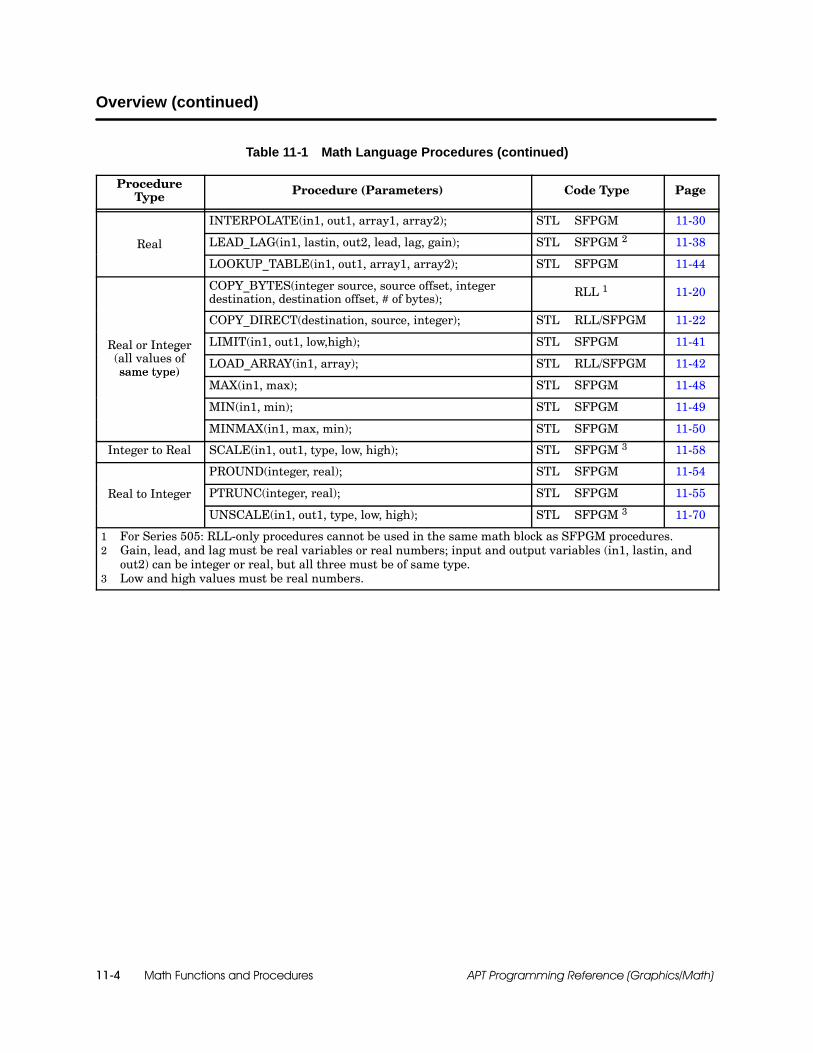
Math Functions and Procedures11-4 APT Programming Reference (Graphics/Math)
Overview (continued)
Table 11-1 Math Language Procedures (continued)
ProcedureType Procedure (Parameters) Code Type Page
INTERPOLATE(in1, out1, array1, array2); STL SFPGM 11-30
Real LEAD_LAG(in1, lastin, out2, lead, lag, gain); STL SFPGM 2 11-38
LOOKUP_TABLE(in1, out1, array1, array2); STL SFPGM 11-44
COPY_BYTES(integer source, source offset, integerdestination, destination offset, # of bytes); RLL 1 11-20
COPY_DIRECT(destination, source, integer); STL RLL/SFPGM 11-22
Real or Integer( ll l f
LIMIT(in1, out1, low,high); STL SFPGM 11-41g(all values ofsame type)
LOAD_ARRAY(in1, array); STL RLL/SFPGM 11-42same type)
MAX(in1, max); STL SFPGM 11-48
MIN(in1, min); STL SFPGM 11-49
MINMAX(in1, max, min); STL SFPGM 11-50
Integer to Real SCALE(in1, out1, type, low, high); STL SFPGM 3 11-58
PROUND(integer, real); STL SFPGM 11-54
Real to Integer PTRUNC(integer, real); STL SFPGM 11-55
UNSCALE(in1, out1, type, low, high); STL SFPGM 3 11-70
1 For Series 505: RLL-only procedures cannot be used in the same math block as SFPGM procedures.2 Gain, lead, and lag must be real variables or real numbers; input and output variables (in1, lastin, and
out2) can be integer or real, but all three must be of same type.3 Low and high values must be real numbers.

Math Functions and Procedures 11-5APT Programming Reference (Graphics/Math)
Table 11-2 Math Language Functions
Type of Function Function (Parameters) Value Type Code Type Page
ABS (expression) Integer or Real STL RLL/SFPGM 11-7
EXP (expression) Real STL SFPGM 11-26
FRAC (expression) Real STL SFPGM 11-28
INT_TO_REAL (expression) Real STL SFPGM 11-34
Arithmetic Functions LN (expression) Real STL SFPGM 11-46
LOG (expression) Real STL SFPGM 11-47
ROUND (expression) Integer STL SFPGM 11-57
SQRT (expression) Real STL SFPGM 11-65
TRUNC (expression) Integer STL SFPGM 11-67
ARCCOS (expression) Real STL SFPGM 11-8
ARCSIN (expression) Real STL SFPGM 11-9
Trigonometric FunctionsARCTAN (expression) Real STL SFPGM 11-10
Trigonometric FunctionsCOS (expression) Real STL SFPGM 11-24
SIN (expression) Real STL SFPGM 11-64
TAN (expression) Real STL SFPGM 11-66
BITS_TO_INT (array variable) Integer STL SFPGM 11-16
BITTEST (variable, integer) Boolean STL RLL 1 11-18
Bit FunctionsEDGE (expression) Boolean STL RLL 1 11-25
Bit FunctionsLEFTSHIFT (expression,expression) Integer STL SFPGM 11-40
RIGHTSHIFT (expression,expression) Integer STL SFPGM 11-56
1 RLL-only functions cannot be used in the same math block as SFPGM functions.

Math Functions and Procedures11-6 APT Programming Reference (Graphics/Math)
Overview (continued)
As a normal part of its operation, a Series 505 controller handles asubroutine that has been compiled into SFPGM code in the following ways:
In some situations, APT allocates locations in Series 505 V-Memory tobe used as compiler internal temporary variables by the subroutine.
The Series 505 controller temporarily suspends execution of thesubroutine in order to enable another subroutine to begin execution.
The combination of these two events can cause a loss of data: the temporaryvariables of the first subroutine may be overwritten during execution of thesubsequent subroutine.
In consequence, if you have a Series 505 controller, you need to observe thefollowing guidelines for math statements used in a subroutine, in order toavoid the possibility of creating temporary variables that risk beingoverwritten during the subroutine’s interruption.
For functions and procedures that accept either a variable or anexpression as a parameter, use only a variable. An expression causestemporary variables to be allocated. You can store the intermediateresults of an expression in a Series 505 T-Memory location beforecalling the subroutine (%Tx, where x = 11--16).
Use the PTRUNC procedure, not the TRUNC function, in user-definedsubroutines.
Use the PROUND procedure, not the ROUND function, in user-definedsubroutines.
Use the PBITS_TO_INT procedure, not the BITS_TO_INT function, inuser-defined subroutines.
NOTE: The EDGE function also stores data temporarily by using internalmemory locations. Therefore, if you have a Series 505 controller, avoid usingEDGE in user-defined subroutines.
Using Functionsand Procedures inSubroutines(Series 505)

ABS
Math Functions and Procedures 11-7APT Programming Reference (Graphics/Math)
11.2 Function and Procedure Definitions
The ABS function is a real or integer function that is available in STL for S5controllers and is available in both RLL and SFPGM for Series 505; ABScan be used with all controllers. ABS returns the positive value of theexpression in parentheses.
To enter the ABS function, use:
ABS(expression)
Expressions, values, or functions can go in the parenthesis as input.
STL and SFPGM can use real or integer functions, but the expressionmust match the returned type. See Figure 11-1.
Series 505 RLL can use only integer; refer to Figure 11-2.
Key word
num3 := ABS(5.65 -- 10.0);
Real number, variable,or expression
Real-typevariable
Figure 11-1 ABS Real Function
Integer number, variable,or expression
num4 := ABS(4--22);
Key word
Integer-typevariable
Figure 11-2 ABS Integer Function
ABS Function
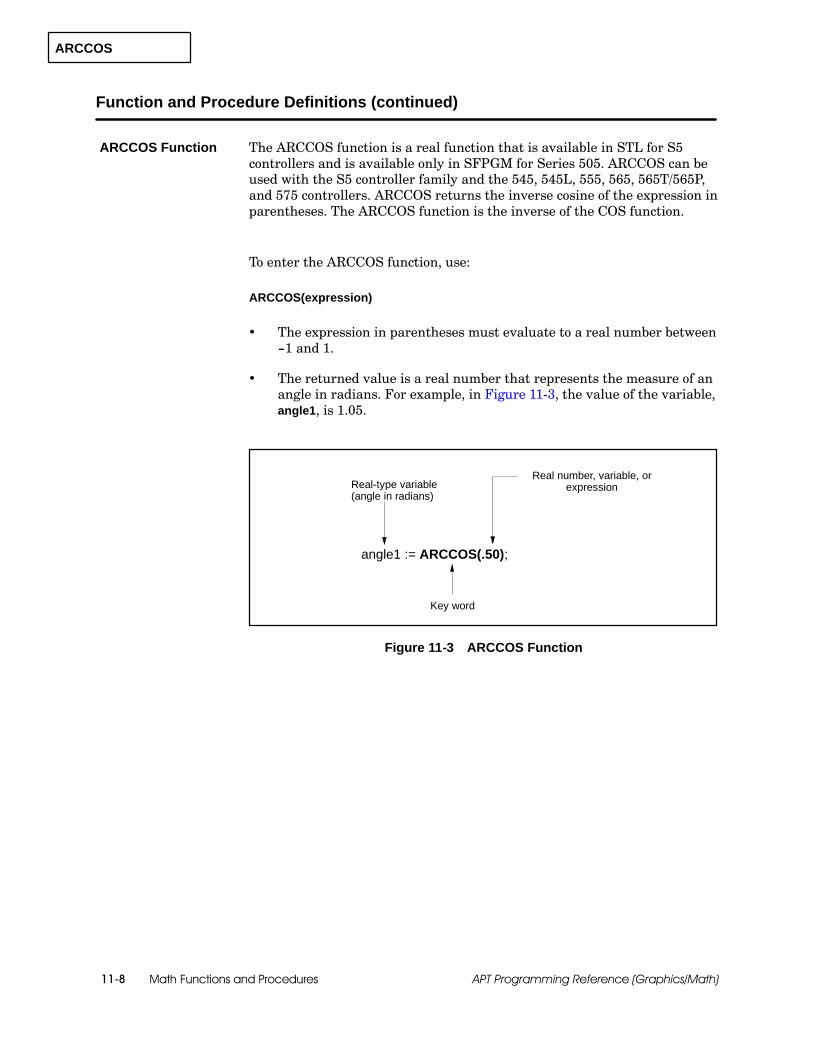
ARCCOS
Math Functions and Procedures11-8 APT Programming Reference (Graphics/Math)
Function and Procedure Definitions (continued)
The ARCCOS function is a real function that is available in STL for S5controllers and is available only in SFPGM for Series 505. ARCCOS can beused with the S5 controller family and the 545, 545L, 555, 565, 565T/565P,and 575 controllers. ARCCOS returns the inverse cosine of the expression inparentheses. The ARCCOS function is the inverse of the COS function.
To enter the ARCCOS function, use:
ARCCOS(expression)
The expression in parentheses must evaluate to a real number between--1 and 1.
The returned value is a real number that represents the measure of anangle in radians. For example, in Figure 11-3, the value of the variable,angle1, is 1.05.
Key word
angle1 := ARCCOS(.50);
Real-type variable(angle in radians)
Real number, variable, orexpression
Figure 11-3 ARCCOS Function
ARCCOS Function
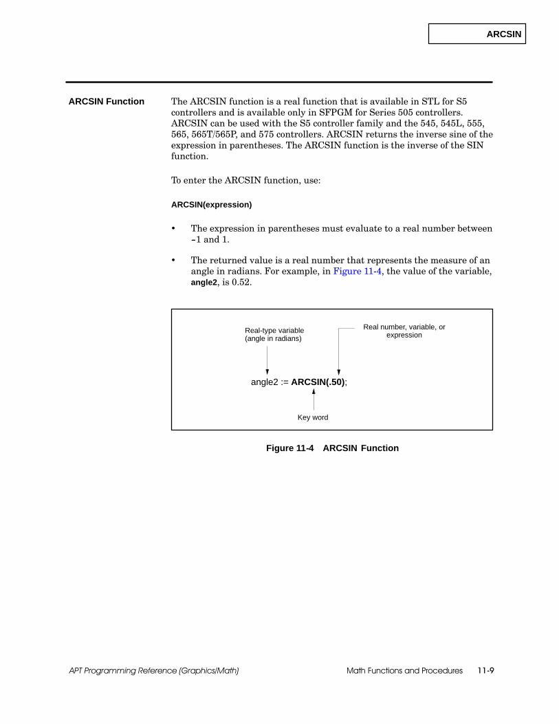
ARCSIN
Math Functions and Procedures 11-9APT Programming Reference (Graphics/Math)
The ARCSIN function is a real function that is available in STL for S5controllers and is available only in SFPGM for Series 505 controllers.ARCSIN can be used with the S5 controller family and the 545, 545L, 555,565, 565T/565P, and 575 controllers. ARCSIN returns the inverse sine of theexpression in parentheses. The ARCSIN function is the inverse of the SINfunction.
To enter the ARCSIN function, use:
ARCSIN(expression)
The expression in parentheses must evaluate to a real number between--1 and 1.
The returned value is a real number that represents the measure of anangle in radians. For example, in Figure 11-4, the value of the variable,angle2, is 0.52.
Key word
angle2 := ARCSIN(.50);
Real-type variable(angle in radians)
Real number, variable, orexpression
Figure 11-4 ARCSIN Function
ARCSIN Function

ARCTAN
Math Functions and Procedures11-10 APT Programming Reference (Graphics/Math)
Function and Procedure Definitions (continued)
The ARCTAN function is a real function that is available in STL for S5controllers and is available only in SFPGM for Series 505 controllers.ARCTAN can be used with the S5 controller family and the 545, 545L, 555,565, 565T/565P, and 575 controllers. ARCTAN returns the inverse tangentof the expression in parentheses. The ARCTAN function is the inverse of theTAN function.
To enter the ARCTAN function, use:
ARCTAN(expression)
The expression in parentheses must evaluate to a real number.
The returned value is a real number that represents the measure of anangle in radians. For example, in Figure 11-5, the value of the variable,angle3, is 0.785.
Key word
angle3 := ARCTAN(1.0);
Real-type variable(angle in radians)
Real number, variable, orexpression
Figure 11-5 ARCTAN Function
ARCTAN Function
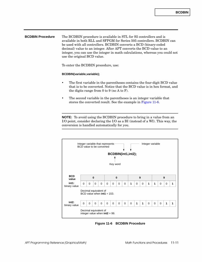
BCDBIN
Math Functions and Procedures 11-11APT Programming Reference (Graphics/Math)
The BCDBIN procedure is available in STL for S5 controllers and isavailable in both RLL and SFPGM for Series 505 controllers. BCDBIN canbe used with all controllers. BCDBIN converts a BCD (binary-codeddecimal) value to an integer. After APT converts the BCD value to aninteger, you can use the integer in math calculations, whereas you could notuse the original BCD value.
To enter the BCDBIN procedure, use:
BCDBIN(variable,variable);
The first variable in the parentheses contains the four-digit BCD valuethat is to be converted. Notice that the BCD value is in hex format, andthe digits range from 0 to 9 (no A to F).
The second variable in the parentheses is an integer variable thatstores the converted result. See the example in Figure 11-6.
NOTE: To avoid using the BCDBIN procedure to bring in a value from anI/O point, consider declaring the I/O as a BI (instead of a WI). This way, theconversion is handled automatically for you.
Integer variable
Key word
BCDBIN(int1,int2);
Integer variable that representsBCD value to be converted
0 0 00 0 1 0 0 1 0 0 110 0 0
0 0 9 9BCDvalue
Decimal equivalent ofBCD value when int1 = 153.
0 0 00 0 0 1 1 0 0 1 100 0 0
Decimal equivalent ofinteger value when int2 = 99.
int1:binary value
int2:binary value
Figure 11-6 BCDBIN Procedure
BCDBIN Procedure

BINBCD
Math Functions and Procedures11-12 APT Programming Reference (Graphics/Math)
Function and Procedure Definitions (continued)
The BINBCD procedure is available in STL for S5 controllers and isavailable in both RLL and SFPGM for Series 505 controllers. BINBCD canbe used with all controllers. BINBCD converts an integer value to a BCD(binary-coded decimal) value. Notice that the BCD value is in hex format,and the digits range from 0 to 9 (no A to F).
To enter the BINBCD procedure, use:
BINBCD (variable,variable);
The first variable in the parentheses contains the integer to beconverted to a BCD value.
The second variable in the parentheses is an integer variable thatstores the converted value (that is, the BCD value). See the example inFigure 11-7.
NOTE: To avoid using the BINBCD procedure to send a value out to an I/Opoint, consider declaring the I/O as a BO (instead of a WO). This way, theconversion is handled automatically for you.
0 0 4 3BCDvalue
Key word
BINBCD(int2,int3);
Integer variable for value afterconversion to BCD
Variable containing integerto be converted
0 0 00 0 0 1 0 0 0 1 100 0 0
Decimal equivalent ofBCD value when int3 = 67.
0 0 00 0 0 0 1 1 0 1 100 0 0
Decimal equivalent ofinteger value when int2 = 43.
int3:binary value
int2:binary value
Figure 11-7 BINBCD Procedure
BINBCD Procedure
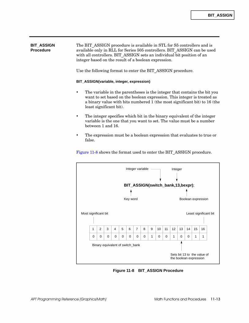
BIT_ASSIGN
Math Functions and Procedures 11-13APT Programming Reference (Graphics/Math)
The BIT_ASSIGN procedure is available in STL for S5 controllers and isavailable only in RLL for Series 505 controllers. BIT_ASSIGN can be usedwith all controllers. BIT_ASSIGN sets an individual bit position of aninteger based on the result of a boolean expression.
Use the following format to enter the BIT_ASSIGN procedure.
BIT_ASSIGN(variable, integer, expression)
The variable in the parentheses is the integer that contains the bit youwant to set based on the boolean expression. This integer is treated asa binary value with bits numbered 1 (the most significant bit) to 16 (theleast significant bit).
The integer specifies which bit in the binary equivalent of the integervariable is the one that you want to set. The value must be a numberbetween 1 and 16.
The expression must be a boolean expression that evaluates to true orfalse.
Figure 11-8 shows the format used to enter the BIT_ASSIGN procedure.
1 2 3 4 5 6 7 8 9 10 11 13 14 15 1612
0
BIT_ASSIGN(switch_bank,13,bexpr);
1 0 0 0 0 1 110 0 0 0 0 00
Most significant bit
Binary equivalent of switch_bank
Least significant bit
Key word
Integer variable Integer
Sets bit 13 to the value ofthe boolean expression
Boolean expression
Figure 11-8 BIT_ASSIGN Procedure
BIT_ASSIGNProcedure
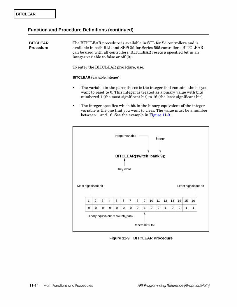
BITCLEAR
Math Functions and Procedures11-14 APT Programming Reference (Graphics/Math)
Function and Procedure Definitions (continued)
The BITCLEAR procedure is available in STL for S5 controllers and isavailable in both RLL and SFPGM for Series 505 controllers. BITCLEARcan be used with all controllers. BITCLEAR resets a specified bit in aninteger variable to false or off (0).
To enter the BITCLEAR procedure, use:
BITCLEAR (variable,integer);
The variable in the parentheses is the integer that contains the bit youwant to reset to 0. This integer is treated as a binary value with bitsnumbered 1 (the most significant bit) to 16 (the least significant bit).
The integer specifies which bit in the binary equivalent of the integervariable is the one that you want to clear. The value must be a numberbetween 1 and 16. See the example in Figure 11-9.
1 2 3 4 5 6 7 8 9 10 11 13 14 15 1612
0 1
BITCLEAR(switch_bank,9);
0 0 0 0 1 110 0 0 0 0 00
Most significant bit
Binary equivalent of switch_bank
Least significant bit
Key word
Integer variableInteger
Resets bit 9 to 0
Figure 11-9 BITCLEAR Procedure
BITCLEARProcedure

BITSET
Math Functions and Procedures 11-15APT Programming Reference (Graphics/Math)
The BITSET procedure is available in STL for S5 controllers and isavailable in both RLL and SFPGM for Series 505 controllers. BITSET canbe used with all controllers. BITSET sets a specified bit in an integervariable to true or on (1).
To enter the BITSET procedure, use:
BITSET (variable,integer);
The variable in the parentheses is the integer that contains the bit youwant to set to 1. This integer is treated as a binary value with bitsnumbered 1 (the most significant bit) to 16 (the least significant bit).
The integer specifies which bit in the binary equivalent of the integervariable is the one that you want to set. The value must be a numberbetween 1 and 16. See the example in Figure 11-10.
Figure 11-10 shows how the BITSET procedure works.
1 2 3 4 5 6 7 8 9 10 11 13 14 15 1612
0
BITSET(switch_bank,13);
1 0 0 0 0 1 110 0 0 0 0 00
Most significant bit
Binary equivalent of switch_bank
Least significant bit
Key word
Integer variableInteger
Sets bit 13 to 1
Figure 11-10 BITSET Procedure
BITSET Procedure

BITS_TO_INT
Math Functions and Procedures11-16 APT Programming Reference (Graphics/Math)
Function and Procedure Definitions (continued)
The BITS_TO_INT function is an integer function that is available in STLfor S5 controllers and is available in both RLL and SFPGM for Series 505controllers. BITS_TO_INT can be used with the S5 controller family and the545, 545L, 555, 565, 565T/565P, and 575 controllers. BITS_TO_INT movesan array of 16 boolean values into an integer variable.
If you have a Series 505 controller, consider using the PACK_BITSprocedure; it generates faster, more efficient code than BITS_TO_INT in aSeries 505 environment.
To enter the BITS_TO_INT function, use:
BITS_TO_INT(variable)
The variable in parentheses must be a boolean array. (A boolean valueof false is a 0; true is a 1.) Element 1 of the array is the most significantbit; element 16 is the least significant bit.
The returned integer value is the decimal equivalent of the binaryvalue constructed from the bit values of the boolean array. For example,in Figure 11-11, the value of the variable binvalue is 147.
BITS_TO_INTFunction

BITS_TO_INT
Math Functions and Procedures 11-17APT Programming Reference (Graphics/Math)
The BITS_TO_INT procedure moves the first element of the array into themost significant bit of the integer (see Figure 11-11). The PACK_BITSprocedure moves the first element of an array into the least significant bit ofthe integer.
[ 16 ]
[ 15 ]
[ 14 ]
[ 13 ]
[ 12 ]
[ 11 ]
[ 10 ]
[ 9 ]
[ 8 ]
[ 7 ]
[ 6 ]
[ 5 ]
[ 4 ]
[ 3 ]
[ 2 ]
[ 1 ]
1100100100000000
MSB LSB
binvalue := BITS_TO_INT(binarray);
Key word
Integer variable Boolean arrayvariable
binarray
binvalue = 147
Figure 11-11 Example of BITS_TO_INT Operation
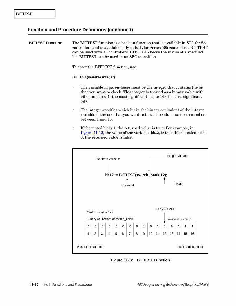
BITTEST
Math Functions and Procedures11-18 APT Programming Reference (Graphics/Math)
Function and Procedure Definitions (continued)
The BITTEST function is a boolean function that is available in STL for S5controllers and is available only in RLL for Series 505 controllers. BITTESTcan be used with all controllers. BITTEST checks the status of a specifiedbit. BITTEST can be used in an SFC transition.
To enter the BITTEST function, use:
BITTEST(variable,integer)
The variable in parentheses must be the integer that contains the bitthat you want to check. This integer is treated as a binary value withbits numbered 1 (the most significant bit) to 16 (the least significantbit).
The integer specifies which bit in the binary equivalent of the integervariable is the one that you want to test. The value must be a numberbetween 1 and 16.
If the tested bit is 1, the returned value is true. For example, inFigure 11-12, the value of the variable, bit12, is true. If the tested bit is0, the returned value is false.
0 1 0 0 0 0 1 110 0 0 0 0 00
bit12 := BITTEST(switch_bank,12);
Most significant bit
Binary equivalent of switch_bank
Switch_bank = 147
Least significant bit
Bit 12 = TRUE
0 = FALSE; 1 = TRUE
1 2 3 4 5 6 7 8 9 10 11 13 14 15 1612
Key word
Integer variableBoolean variable
Integer
Figure 11-12 BITTEST Function
BITTEST Function

CLEAR
Math Functions and Procedures 11-19APT Programming Reference (Graphics/Math)
The CLEAR procedure is available in STL for S5 controllers and is availableonly in RLL for Series 505. It can be used with all controllers. CLEAR setsthe APT flag value to off (false) after the procedure is executed. The APTflag remains off, even if the block is disabled, until a LATCH or ON sets it toon. CLEAR takes precedence over ON or LATCH.
To enter the CLEAR procedure, use:
CLEAR (flag_variable);
The variable in the parentheses is the APT flag that is turned off(false). See the example in Figure 11-13.
Key word
CLEAR (Flag_A);
APT flag variable
Figure 11-13 CLEAR Procedure
CLEAR Procedure
COPY_BYTES
Math Functions and Procedures11-20 APT Programming Reference (Graphics/Math)
Function and Procedure Definitions (continued)
The COPY_BYTES procedure is not available for S5 controllers; it isavailable only in RLL for Series 505 controllers. It can only be used withsupported releases of the 545, 545L, 555, and 575 controllers.COPY_BYTES copies one or more bytes from one memory region to another.Refer to Chapter 1 in the SIMATIC APT Programming Reference (Tables)Manual for controller release-specific features.
Use the following format to enter the COPY_BYTES procedure.
COPY_BYTES(source, source offset, destination, destination offset, # of bytes)
Source Identifies the starting integer address for the source. It can beeither a direct address or a declared integer variable. For Series 505controllers, you can use V, G, VMS, or VMM word memory.
Source Offset The integer value may either be 0, for no offset, or 1, for anoffset of one byte.
Destination Identifies the starting integer address for the destination. Itcan be either a direct address or a declared integer variable. For Series 505controllers, you can use V, G, VMS, or VMM word memory.
Destination Offset The integer value may either be 0, for no offset, or 1,for an offset of one byte.
Number of Bytes An integer representing the number of bytes to copyfrom the source to the destination.
! WARNINGThe COPY_BYTES procedure allows you to copy large amount of data tospecified memory locations within the controller. APT does not check to see ifthese memory locations are currently in use by other sections of the APTprogram.
Overwriting controller memory could cause unpredictable operation, whichcould result in death or serious injury to personnel and/or equipment.
Be sure to reserve the appropriate amount of memory in the Compiler ControlFile and use only those memory locations in this procedure.
COPY_BYTESProcedure

COPY_BYTES
Math Functions and Procedures 11-21APT Programming Reference (Graphics/Math)
In Figure 11-14, 32 bytes are copied from the Series 505 address,%VMM0F000, and there is no offset to the VMM address of the declaredvariable, TABLE. This example uses a Series 505 direct address.
COPY_BYTES (%VMM0F000,0,table,0,32);
Key word
Source word address orinteger variable Source integer offset
Destination integeroffset
# of bytesDestination word address orinteger variable
Figure 11-14 COPY_BYTES Procedure

COPY_DIRECT
Math Functions and Procedures11-22 APT Programming Reference (Graphics/Math)
Function and Procedure Definitions (continued)
The COPY_DIRECT procedure is available in STL for S5 controllers and isavailable in both RLL and SFPGM for Series 505 controllers.COPY_DIRECT can be used with all controllers. COPY_DIRECT moves ablock of data from one location to another.
To enter the COPY_DIRECT procedure, use:
COPY_DIRECT(destination,source,integer);
Destination Identifies the starting address of the destination incontroller memory. For S5 controllers, must be a declared array variable.For Series 505 controllers, can be either a declared array variable or else adirect address that is associated with a block of reserved memory.
Source For S5 controllers, must be a declared array variable. For Series505 controllers, can be either a declared array variable or else a directaddress that is associated with a block of reserved memory. If the values inthe array are real, each value requires two locations in Series 505 reservedmemory or in S5 data-word memory; four locations are required if you useS5 flag-word memory. See the examples in Figure 11-15.
Integer Indicates the number of elements that you want to copy from thebeginning of the array into the specified controller memory locations.
An integer array that you want to use in a COPY_DIRECT procedure cancontain as many as 32,767 elements for a Series 505 controller, or 256 for anS5 controller. A real array can contain 16,383 elements, if you have a Series505 controller, or 128 if you have an S5.
! WARNINGThe COPY_DIRECT procedure allows you to copy large amount of data tospecified memory locations within the controller. APT does not check to see ifthese memory locations are currently in use by other sections of the APTprogram.
Overwriting controller memory could cause unpredictable operation, whichcould result in death or serious injury to personnel and/or equipment.
Be sure to reserve the appropriate amount of memory in the Compiler ControlFile and use only those memory locations in this procedure.
Figure 11-15 shows how the COPY_DIRECT procedure works.
COPY_DIRECTProcedure

COPY_DIRECT
Math Functions and Procedures 11-23APT Programming Reference (Graphics/Math)
S5 Data Word Memory
DB7:DW100DB7:DW101
intarray
intarray[1] = 0
intarray[3] = 5
intarray[2] = 2
realarray
COPY_DIRECT (%V100.,realarray,5);
realarray1[1] = 0.5
Key word Number of elements to be copied
Source
Real array
realarray1[5] = 5.0
realarray1[4] = 2.5
realarray1[3] = 0.6
realarray1[2] = 1.5
COPY_DIRECT (intarray,%V200,3); Integer array
Destination
0.5
1.5
0.6
2.5
5.0
S5 Flag Memory
0 FW200
5 FW204
2 FW202
505 V-memory
0 V200
5 V202
2 V201
505 V-Memory
0.5
1.5
0.6
2.5
5.0
V100V101
V102V103
V104V105
V106V107
V108V109
COPY_DIRECT (TANK_LVLS,realarray,5); Real array
(Series 505)
(Series 505)
(S5)
(S5) COPY_DIRECT (intarray,TANK_HT,3); Integer array
DB7:DW102DB7:DW103
DB7:DW104DB7:DW105
DB7:DW106DB7:DW107
DB7:DW108DB7:DW109
Data is moved from the Series 505 or S5 controller memory locations to the integer array (destination).
Data is moved from the real array (source) to the Series 505 or S5 controller memory locations.
For the Series 505 example, %V100 is used as the destination. For the S5 example, TANK_LVLS is the destination.
Assume TANK_LVLSstarts at DB7:DW100
Assume TANK_HTstarts at FW200
The real array in the examples above is used as the source; it supplies data to a destination.
The integer array in the examples above is used as the destination; it receives data from a source location.For the Series 505 example, %V200 is used as the source. For the S5 example, TANK_HT is the source.
Figure 11-15 COPY_DIRECT Procedure

COS
Math Functions and Procedures11-24 APT Programming Reference (Graphics/Math)
Function and Procedure Definitions (continued)
The COS function is a real function that is available in STL for S5controllers and is available only in SFPGM for Series 505 controllers. COScan be used with the S5 controller family and the 545, 545L, 555, 565,565T/565P, and 575 controllers. COS returns the cosine of the expression inparentheses. The COS function is the inverse of the ARCCOS function.
To enter the COS function, use:
COS(expression)
The expression in parentheses must evaluate to a real number thatrepresents the measure of an angle in radians.
For S5 controllers, the expression cannot evaluate to a negativenumber, and it must represent radians in the range 0--2↓.
The returned value is a real number between --1 and 1. For example, inFigure 11-16, the value of the variable, angle1, is 0.50.
angle1 := COS(60.0 * 3.14159 / 180.0);
Key word
Real-type variable
Real number, variable, orexpression that represents anangle in radians
Figure 11-16 COS Function
COS Function

EDGE
Math Functions and Procedures 11-25APT Programming Reference (Graphics/Math)
The EDGE function is a boolean function that is available in STL for S5controllers and is available only in RLL for Series 505. It can be used withall controllers. EDGE detects a change from false to true in the value of aboolean expression. EDGE can be used in an SFC transition.
NOTE: For Series 505 controllers, avoid using EDGE in user-definedsubroutines, since the EDGE function stores data temporarily by usinginternal memory locations.
To enter the EDGE function, use:
EDGE(expression)
The variable in parentheses is a boolean value that is monitored todetect the first time the expression changes from false to true.
When that expression changes from false to true, the returned value ofthe function becomes true and remains true for one scan of thecontroller.
The returned value is a boolean variable.
In Figure 11-17, assume that bool1 and bool2 are declared as booleanvalues. In the first example, bool2 detects a false to true transition in bool1.In the second example, bool2 detects a true to false transition in bool1.
Key word
bool2 := EDGE(bool1);
Boolean expressionBoolean variable
bool2 := EDGE(NOT(bool1));
Figure 11-17 EDGE Function
EDGE Function

EXP
Math Functions and Procedures11-26 APT Programming Reference (Graphics/Math)
Function and Procedure Definitions (continued)
The EXP function is a real function that is available in STL for S5controllers and is available only in SFPGM for Series 505 controllers. EXPcan be used with the S5 controller family and the 545, 545L, 555, 565,565T/565P, and 575 controllers. EXP returns the value of e (2.71828) raisedto the power represented by the expression in parentheses. (The EXPfunction is the inverse of the LN function.)
To enter the EXP function, use:
EXP(expression)
The expression in parentheses must evaluate to a real number.
The returned value is also a real number. For example, in Figure 11-18,the value of the variable, real1, is 2.7.
Key word
real1 := EXP(1.0);
Real-type variable
Real number, variable, orexpression
Figure 11-18 EXP Function
EXP Function

FRS
Math Functions and Procedures 11-27APT Programming Reference (Graphics/Math)
The Forced Role Swap (FRS) procedure is available in STL for S5controllers, and is available only in RLL for Series 505 controllers. FRS canbe used with the S5 948R and the SIMATIC 560, 560T, 565, 565T, and 565Pcontrollers. This procedure allows you to change the roles of the controllersso that the current standby unit becomes active and the current active unitbecomes the standby.
To enter the FRS procedure, use:
FRS (bexpr,out_bit);
BEXPR — a boolean expression that triggers the forced role swap.
OUT_BIT — a boolean value that is turned on after the role swapoccurs. See Figure 11-19.
If an active controller with a standby detects an off-to-on transition on theinput (BEXPR), it queues a role swap to occur at the beginning of the nextcontroller scan. OUT_BIT is turned on when the forced role swap isexecuted.
Key word
FRS (bexpr,out_bit);
Booleanexpression
Booleanvariable
Figure 11-19 FRS Procedure
NOTE: For S5 controllers, APT uses FW0 (FY0 and FY1) as the H-flag wordfor redundant control.
FRS Procedure

FRAC
Math Functions and Procedures11-28 APT Programming Reference (Graphics/Math)
Function and Procedure Definitions (continued)
The FRAC function is a real function that is available in STL for S5controllers and is available only in SFPGM for Series 505 controllers. FRACcan be used with S5 controllers and with the 545, 545L, 555, 565,565T/565P, and 575 controllers. FRAC returns the fractional portion of theexpression in parentheses.
To enter the FRAC function, use:
FRAC(expression)
The expression in parentheses must evaluate to a real number.
The returned value is also a real number. For example, in Figure 11-20,the value of the variable, real2, is 0.25.
If the expression in parentheses is negative, the result of the FRACfunction is also negative.
FRAC Function
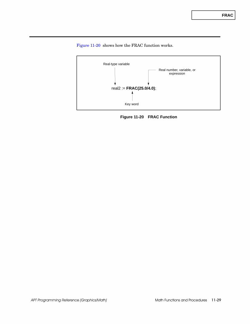
FRAC
Math Functions and Procedures 11-29APT Programming Reference (Graphics/Math)
Figure 11-20 shows how the FRAC function works.
Key word
real2 := FRAC(25.0/4.0);
Real-type variable
Real number, variable, orexpression
Figure 11-20 FRAC Function
INTERPOLATE
Math Functions and Procedures11-30 APT Programming Reference (Graphics/Math)
Function and Procedure Definitions (continued)
The INTERPOLATE procedure is available in STL for S5 controllers and isavailable only in SFPGM for Series 505 controllers. INTERPOLATE can beused with the S5 controller family and the 545, 545L, 555, 565, 565T/565P,and 575 controllers. This procedure calculates a value between two knownvalues.
INTERPOLATE first locates an input value an input array and then usesone of the following techniques to determine the output.
If the input is equal to an element of the input array, the output isassigned the value of the same element in the output array.
If the input falls between two elements in the array, INTERPOLATEcalculates the relative position between the two elements and uses thiscalculation in determining the output.
If the input is less than the value of the first element in the inputarray, the output is assigned a value less than the value of the firstelement in the output array. This value is based on the relationshipcalculated between the input value and the values of the first twoelements in the input array.
If the input is greater than the value of the last element of the inputarray, the output is assigned a value greater than the value of the lastelement of the output array. This value is based on the relationshipcalculated between the input value and the values of the last twoelements in the input array.
When you declare the arrays that you want to use in an INTERPOLATEprocedure, you must specify 11 as the number of elements in each array.
INTERPOLATEProcedure

INTERPOLATE
Math Functions and Procedures 11-31APT Programming Reference (Graphics/Math)
To enter the INTERPOLATE procedure, use:
INTERPOLATE(input variable,output variable,input array,output array);
The input variable must be a real variable.
The output variable is a real variable that stores the result of theINTERPOLATE procedure. See the example in Figure 11-21.
The input array is an 11-element array of real numbers. The values inthe array must be arranged in ascending order.
The output array is an 11-element array of real numbers. The values inthe array must be arranged in the same order as the input array.
xin = 0.5
INTERPOLATE (xin,xout,inarray,outarray);
xout = 765.0
Key word
Real variable
Input arrayof real values
Realvariable
Output arrayof real values
Input value Output valueinput array
inarray[1] = 0.2
inarray[5] = 1.0
inarray[4] = 0.8
inarray[3] = 0.6
inarray[2] = 0.4
output array
outarray[1] = 750.0
outarray[5] = 790.0
outarray[4] = 780.0
outarray[3] = 770.0
outarray[2] = 760.0
inarray[11] = 2.2
inarray[10] = 2.0
outarray[11] = 850.0
outarray[10] = 840.0
.
.
.
.
.
.
Figure 11-21 INTERPOLATE Procedure

INT_TO_BITS
Math Functions and Procedures11-32 APT Programming Reference (Graphics/Math)
Function and Procedure Definitions (continued)
The INT_TO_BITS procedure is available in STL for S5 controllers and isavailable in both RLL and SFPGM for Series 505. It can be used with allcontrollers. INT_TO_BITS converts an integer value to an array of 16boolean values.
Consider using the UNPACK_BITS procedure; UNPACK_BITS generatesfaster, more efficient code than INT_TO_BITS.
To enter the INT_TO_BITS procedure, use:
INT_TO_BITS(variable,variable);
The first variable in parentheses must be a 16-bit boolean array. A 0 bitequals a boolean value of false; 1 equals true. The most significant bitbecomes element 1 of the array; the least significant bit becomeselement 16.
The second variable contains the integer that is to be converted. Seethe example in Figure 11-22.
INT_TO_ BITS(binarray,147);
Key word
Integer orinteger variable
Boolean arrayvariable
Figure 11-22 INT_TO_BITS Procedure
INT_TO_BITSProcedure
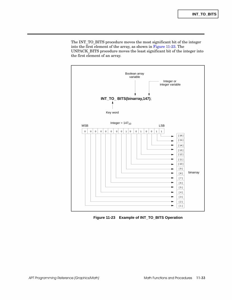
INT_TO_BITS
Math Functions and Procedures 11-33APT Programming Reference (Graphics/Math)
The INT_TO_BITS procedure moves the most significant bit of the integerinto the first element of the array, as shown in Figure 11-23. TheUNPACK_BITS procedure moves the least significant bit of the integer intothe first element of an array.
[ 1 ]
[ 2 ]
[ 3 ]
[ 4 ]
[ 5 ]
[ 6 ]
[ 7 ]
[ 8 ]
[ 9 ]
[ 10 ]
[ 11 ]
[ 12 ]
[ 13 ]
[ 14 ]
[ 15 ]
[ 16 ]
0 0 0 0 0 0 0 0 1 0 0 1 0 0 1 1
MSB LSB
INT_TO_ BITS(binarray,147);
Key word
Integer orinteger variable
Boolean arrayvariable
binarray
Integer = 14710
Figure 11-23 Example of INT_TO_BITS Operation
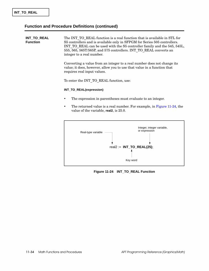
INT_TO_REAL
Math Functions and Procedures11-34 APT Programming Reference (Graphics/Math)
Function and Procedure Definitions (continued)
The INT_TO_REAL function is a real function that is available in STL forS5 controllers and is available only in SFPGM for Series 505 controllers.INT_TO_REAL can be used with the S5 controller family and the 545, 545L,555, 565, 565T/565P, and 575 controllers. INT_TO_REAL converts aninteger to a real number.
Converting a value from an integer to a real number does not change itsvalue; it does, however, allow you to use that value in a function thatrequires real input values.
To enter the INT_TO_REAL function, use:
INT_TO_REAL(expression)
The expression in parentheses must evaluate to an integer.
The returned value is a real number. For example, in Figure 11-24, thevalue of the variable, real2, is 25.0.
Key word
real2 := INT_TO_REAL(25);
Real-type variable
Integer, integer variable,or expression
Figure 11-24 INT_TO_REAL Function
INT_TO_REALFunction

IREAD
Math Functions and Procedures 11-35APT Programming Reference (Graphics/Math)
The IREAD procedure is available in STL for S5 controllers and is availableonly in RLL for Series 505 controllers. It can be used with the S5 controllerfamily and the 545, 545L, 555, and 575 controllers. IREAD performs animmediate read of a digital or word input from a module to the imageregister. Any reference to the associated I/O point gets the updated fieldvalue. Refer to the SIMATIC TI505 Programming Reference Manual for alist of Series 505 modules that support this procedure. All digital inputmodules for S5 support the IREAD procedure.
Use the following format to enter the IREAD procedure.
IREAD(Variable)
The variable in parentheses must be a digital or word input from asupported module in base 0 for Series 505 controllers; the module canbe located in any base for an S5 controller. See the example inFigure 11-25.
Key word
IREAD(Count);
Digital or word inputvariable
Figure 11-25 IREAD Procedure
! WARNINGFor Series 505 controllers, the IREAD procedure is only available for inputpoints of a supported module in base 0 (zero). APT cannot determine whetherthe input points meet these requirements.
Failure to use the IREAD procedure correctly can cause your Series 505controller to operate in an unpredictable manner, or to fail in an unsafecondition that could result in death or serious injury and/or equipment damage.
Do not use the IREAD procedure unless you are certain that the input pointsmeet the stated requirements.
IREAD Procedure
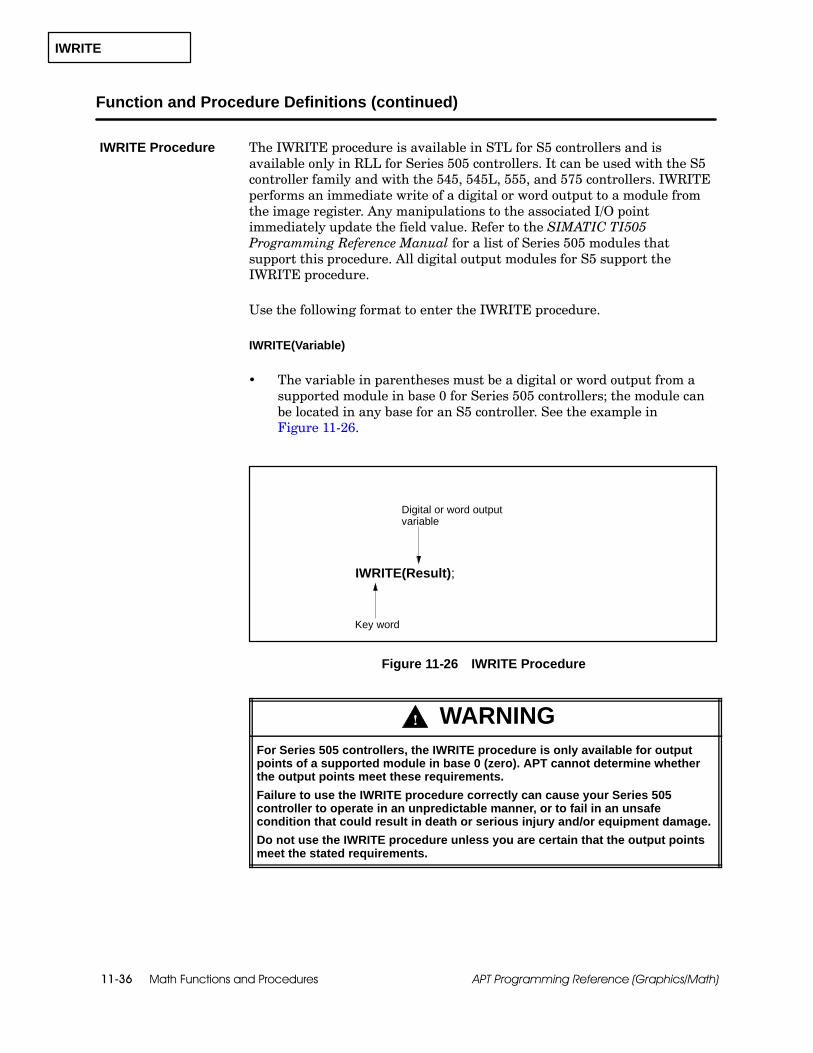
IWRITE
Math Functions and Procedures11-36 APT Programming Reference (Graphics/Math)
Function and Procedure Definitions (continued)
The IWRITE procedure is available in STL for S5 controllers and isavailable only in RLL for Series 505 controllers. It can be used with the S5controller family and with the 545, 545L, 555, and 575 controllers. IWRITEperforms an immediate write of a digital or word output to a module fromthe image register. Any manipulations to the associated I/O pointimmediately update the field value. Refer to the SIMATIC TI505Programming Reference Manual for a list of Series 505 modules thatsupport this procedure. All digital output modules for S5 support theIWRITE procedure.
Use the following format to enter the IWRITE procedure.
IWRITE(Variable)
The variable in parentheses must be a digital or word output from asupported module in base 0 for Series 505 controllers; the module canbe located in any base for an S5 controller. See the example inFigure 11-26.
Key word
IWRITE(Result);
Digital or word outputvariable
Figure 11-26 IWRITE Procedure
! WARNINGFor Series 505 controllers, the IWRITE procedure is only available for outputpoints of a supported module in base 0 (zero). APT cannot determine whetherthe output points meet these requirements.
Failure to use the IWRITE procedure correctly can cause your Series 505controller to operate in an unpredictable manner, or to fail in an unsafecondition that could result in death or serious injury and/or equipment damage.
Do not use the IWRITE procedure unless you are certain that the output pointsmeet the stated requirements.
IWRITE Procedure

LATCH
Math Functions and Procedures 11-37APT Programming Reference (Graphics/Math)
The LATCH procedure is available in STL for S5 controllers and is availableonly in RLL for Series 505 controllers. It can be used with all controllers.LATCH sets the APT flag value to on (true) after the procedure is executedin the math block. The APT flag remains on, even if the block is disabled,until a CLEAR sets it to off (false).
To enter the LATCH procedure, use:
LATCH (flag_variable);
The variable in the parentheses is the APT flag that is turned on (true).See the example in Figure 11-27.
Key word
LATCH (Flag_A);
APT flag variable
Figure 11-27 LATCH Procedure
LATCH Procedure

LEAD_LAG
Math Functions and Procedures11-38 APT Programming Reference (Graphics/Math)
Function and Procedure Definitions (continued)
The LEAD_LAG procedure is available in STL for S5 controllers and isavailable only in SFPGM for Series 505 controllers. LEAD_LAG can be usedwith the S5 controller family and the 545, 545L, 555, 565, 565T/565P, and575 controllers. This procedure calculates an output based on an input andthe specified gain, lead, and lag values. Use the procedure only in acontinuous function block that includes a sample time (“sample” mathblock).
To enter the LEAD_LAG procedure shown in Figure 11-28, use:
LEAD_LAG(input variable,previous input,output variable,lead,lag,gain);
The first three variables in parentheses can be real or integer values,but all three must be the same type. Lead, lag, and gain must be realvariables or real numbers.
The input variable is the input value.
Previous input stores the value of the last input.
The output variable is the variable that stores the result of theLEAD_LAG procedure.
Lead (TLead) specifies a time in minutes that is associated with theresponse immediately after a change in the input.
Lag (TLag) specifies the time in minutes required to reach 63.2 percentof the final output after a change in the input.
Gain specifies the ratio of the change in output to the change in inputat a steady state, as shown in the following equation.
Gain =∆ output∆ input
Saves previousinput value
LEAD_LAG (in1,lastin,out1,tlead,tlag,k);
Key word
Inputvariable
Outputvariable
Gain
Lead timeLag time
Figure 11-28 LEAD_LAG Procedure
LEAD_LAGProcedure

LEAD_LAG
Math Functions and Procedures 11-39APT Programming Reference (Graphics/Math)
The LEAD_LAG algorithm uses the following equation.
Yn= Æ TLagTLag + TsÉ Yn−1+ Gain ÆTLead + TsTLag + Ts
É Xn− GainÆ TLeadTLag + TsÉ Xn−1
where Yn= present output, Yn−1= previous output,Xn= present input, Xn–1= previous input, andTs= sample time in minutes.
The output depends on the ratio of lead to lag as explained below. Assumethe following values in each example: ∆ input and gain = 1.0
If TLead / TLag is greater than 1.0, then the initial response overshoots thesteady-state output value.
Initial output= ∆input * Gain ÆTLeadTLagÉ = 1.0 * 1.0 Æ2.0
1.0É = 2.0
2.0
n = 1 2 3
Yn
0
steady---state output = 1.0
4
If TLead / TLag is less than 1.0, then the initial response undershoots thesteady-state output value.
Initial output= ∆input * Gain ÆTLeadTLagÉ = 1.0 * 1.0 Æ1.02.0É = 0.5
0.5
n = 1 2 3
Yn
0
steady---state output = 1.0
4
If TLead / TLag is equal to 1.0, then the initial response instantaneouslyreaches the steady-state output value.
Initial output= ∆input * Gain ÆTLeadTLagÉ = 1.0 * 1.0 Æ1.0
1.0É = 1.0
n = 1 2 3
Yn
0
steady---state output = 1.0
4
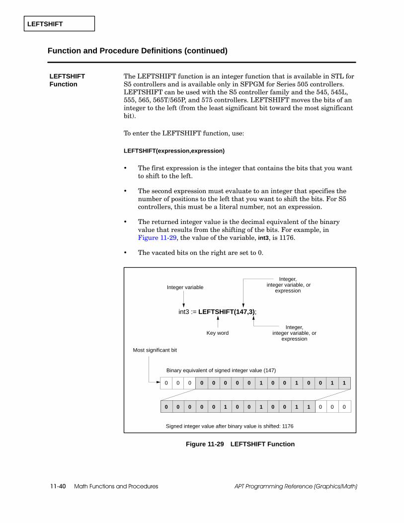
LEFTSHIFT
Math Functions and Procedures11-40 APT Programming Reference (Graphics/Math)
Function and Procedure Definitions (continued)
The LEFTSHIFT function is an integer function that is available in STL forS5 controllers and is available only in SFPGM for Series 505 controllers.LEFTSHIFT can be used with the S5 controller family and the 545, 545L,555, 565, 565T/565P, and 575 controllers. LEFTSHIFT moves the bits of aninteger to the left (from the least significant bit toward the most significantbit).
To enter the LEFTSHIFT function, use:
LEFTSHIFT(expression,expression)
The first expression is the integer that contains the bits that you wantto shift to the left.
The second expression must evaluate to an integer that specifies thenumber of positions to the left that you want to shift the bits. For S5controllers, this must be a literal number, not an expression.
The returned integer value is the decimal equivalent of the binaryvalue that results from the shifting of the bits. For example, inFigure 11-29, the value of the variable, int3, is 1176.
The vacated bits on the right are set to 0.
Integer,integer variable, or
expression
Key word
int3 := LEFTSHIFT(147,3);
Integer variable
0 1 0 0 0 0 110 0 0 0 0 00
Most significant bit
Binary equivalent of signed integer value (147)
0 1 0 0 0 0 1 1 0 00 0 0 0 0
Signed integer value after binary value is shifted: 1176
Integer,integer variable, or
expression
1
1
Figure 11-29 LEFTSHIFT Function
LEFTSHIFTFunction

LIMIT
Math Functions and Procedures 11-41APT Programming Reference (Graphics/Math)
The LIMIT procedure is available in STL for S5 controllers and is availableonly in SFPGM for Series 505 controllers. LIMIT can be used with the S5controller family and the 545, 545L, 555, 565, 565T/565P, and 575controllers. The LIMIT procedure restricts the value of a variable. LIMITcopies the input value to the output variable and ensures that the output isbetween the specified high and low limits.
To enter the LIMIT procedure, use:
LIMIT(low-limit variable,high-limit variable,input variable,output variable);
The input and output variables and the limit variables can be eitherreal or integer values; but all of the values in the parentheses must bethe same type. For example, if the input is a real value, the outputvariable and limit variables must also be real.
If the input is greater than or equal to the low limit and less than orequal to the high limit, the output is assigned the input value. Forexample, in Figure 11-30, if you assume the values under each variablein the first procedure, test1 is 4.2.
If the input is greater than the high limit, the output is assigned thehigh-limit value.
If the input is less than the low limit, the output is assigned thelow-limit value. For example, in Figure 11-30, if you assume the valuesunder each variable in the second procedure, test2 is --3.
Low-limit variable
LIMIT( low1,high1,real1,test1);
Input variable
LIMIT(low2,high2,int2,test2);
Output variableKey word
High-limit variable
Real values: test1 = 4.2
Integer values: test2 = --3
--3.7 4.28.0
--4--3 8
Figure 11-30 LIMIT Procedure
LIMIT Procedure
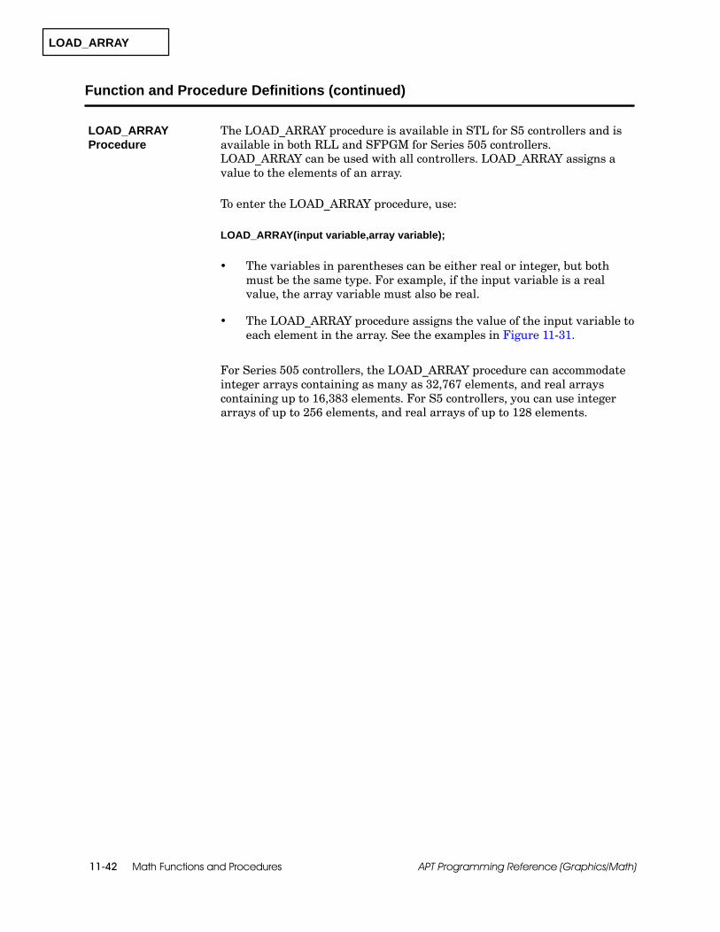
LOAD_ARRAY
Math Functions and Procedures11-42 APT Programming Reference (Graphics/Math)
Function and Procedure Definitions (continued)
The LOAD_ARRAY procedure is available in STL for S5 controllers and isavailable in both RLL and SFPGM for Series 505 controllers.LOAD_ARRAY can be used with all controllers. LOAD_ARRAY assigns avalue to the elements of an array.
To enter the LOAD_ARRAY procedure, use:
LOAD_ARRAY(input variable,array variable);
The variables in parentheses can be either real or integer, but bothmust be the same type. For example, if the input variable is a realvalue, the array variable must also be real.
The LOAD_ARRAY procedure assigns the value of the input variable toeach element in the array. See the examples in Figure 11-31.
For Series 505 controllers, the LOAD_ARRAY procedure can accommodateinteger arrays containing as many as 32,767 elements, and real arrayscontaining up to 16,383 elements. For S5 controllers, you can use integerarrays of up to 256 elements, and real arrays of up to 128 elements.
LOAD_ARRAYProcedure
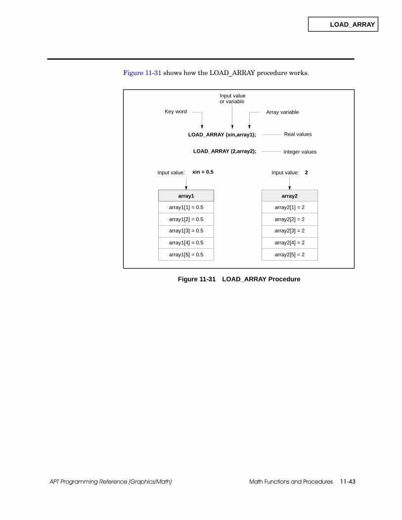
LOAD_ARRAY
Math Functions and Procedures 11-43APT Programming Reference (Graphics/Math)
Figure 11-31 shows how the LOAD_ARRAY procedure works.
array1
LOAD_ARRAY (xin,array1);
array1[1] = 0.5
xin = 0.5
Key word
Input valueor variable
Array variable
Real values
Input value:
array1[5] = 0.5
array1[4] = 0.5
array1[3] = 0.5
array1[2] = 0.5
LOAD_ARRAY (2,array2); Integer values
array2
array2[1] = 2
2Input value:
array2[5] = 2
array2[4] = 2
array2[3] = 2
array2[2] = 2
Figure 11-31 LOAD_ARRAY Procedure

LOOKUP_TABLE
Math Functions and Procedures11-44 APT Programming Reference (Graphics/Math)
Function and Procedure Definitions (continued)
The LOOKUP_TABLE procedure is available in STL for S5 controllers andis available only in SFPGM for Series 505 controllers. LOOKUP_TABLE canbe used with the S5 controller family and the 545, 545L, 555, 565,565T/565P, and 575 controllers. LOOKUP_TABLE determines an outputvalue based on the relative position of an input value in an array of values.
The LOOKUP_TABLE procedure compares the input to the values in theinput array and uses one of the following techniques to determine theoutput.
If the input is equal to an element of the input array, the output isassigned the value of the same element in the output array.
If the input is not equal to an element in the input array,LOOKUP_TABLE uses the value of the highest element that is notgreater than the input. The output is assigned the value of the sameelement in the output array.
If the input is less than the first element in the input array, the outputis assigned the value of the first element in the output array.
If the input is greater than any element in the input array, the outputis assigned the value of the last element in the output array.
When you declare the arrays that you want to use in a LOOKUP_TABLEprocedure, you must specify 11 as the number of elements in each array.
LOOKUP_TABLEProcedure

LOOKUP_TABLE
Math Functions and Procedures 11-45APT Programming Reference (Graphics/Math)
To enter the LOOKUP_TABLE procedure, use:
LOOKUP_TABLE(input variable,output variable,input array,output array);
The input variable must be a real variable.
The output variable is a real variable that stores the result of theLOOKUP_TABLE procedure. See the example in Figure 11-32.
The input array must be an 11-element array variable and mustcontain real numbers. Values in the array must be arranged inascending order.
The output array must be an 11-element array variable and mustcontain real numbers. Values in the array must be arranged in thesame order as the input array.
xin = 0.5
LOOKUP_TABLE (xin,xout,inarray,outarray);
xout = 760.0
Key word
Real variable
Input arrayof real values
Realvariable
Output arrayof real values
Input value Output value
input array
inarray[1] = 0.2
inarray[5] = 1.0
inarray[4] = 0.8
inarray[3] = 0.6
inarray[2] = 0.4
output array
outarray[1] = 750.0
outarray[5] = 790.0
outarray[4] = 780.0
outarray[3] = 770.0
outarray[2] = 760.0
inarray[11] = 2.2
inarray[10] = 2.0
outarray[11] = 850.0
outarray[10] = 840.0
.
.
.
.
.
.
Figure 11-32 LOOKUP_TABLE Procedure
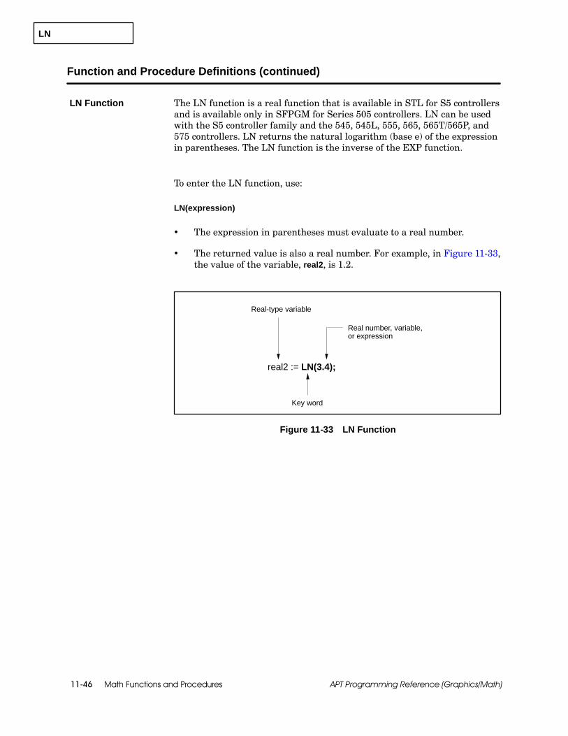
LN
Math Functions and Procedures11-46 APT Programming Reference (Graphics/Math)
Function and Procedure Definitions (continued)
The LN function is a real function that is available in STL for S5 controllersand is available only in SFPGM for Series 505 controllers. LN can be usedwith the S5 controller family and the 545, 545L, 555, 565, 565T/565P, and575 controllers. LN returns the natural logarithm (base e) of the expressionin parentheses. The LN function is the inverse of the EXP function.
To enter the LN function, use:
LN(expression)
The expression in parentheses must evaluate to a real number.
The returned value is also a real number. For example, in Figure 11-33,the value of the variable, real2, is 1.2.
Real number, variable,or expression
Key word
real2 := LN(3.4);
Real-type variable
Figure 11-33 LN Function
LN Function

LOG
Math Functions and Procedures 11-47APT Programming Reference (Graphics/Math)
The LOG function is a real function that is available in STL for S5controllers and is available only in SFPGM for Series 505 controllers. LOGcan be used with the S5 controller family and the 545, 545L, 555, 565,565T/565P, and 575 controllers. LOG returns the common logarithm (base10) of the expression in parentheses.
To enter the LOG function, use:
LOG(expression)
The expression in parentheses must evaluate to a real number.
The returned value is also a real number. For example, inFigure 11-34, the value of the variable, real3, is 2.0.
Key word
real3 := LOG(100.0);
Real-type variable
Real number, variable,or expression
Figure 11-34 LOG Function
LOG Function
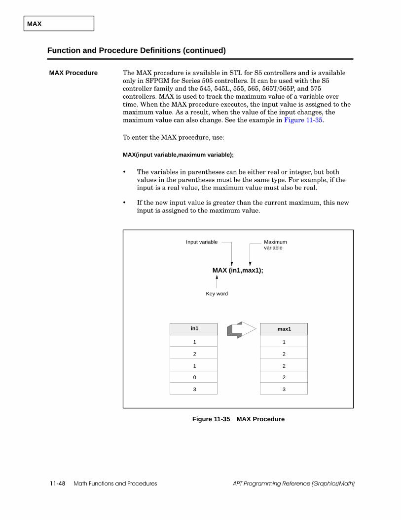
MAX
Math Functions and Procedures11-48 APT Programming Reference (Graphics/Math)
Function and Procedure Definitions (continued)
The MAX procedure is available in STL for S5 controllers and is availableonly in SFPGM for Series 505 controllers. It can be used with the S5controller family and the 545, 545L, 555, 565, 565T/565P, and 575controllers. MAX is used to track the maximum value of a variable overtime. When the MAX procedure executes, the input value is assigned to themaximum value. As a result, when the value of the input changes, themaximum value can also change. See the example in Figure 11-35.
To enter the MAX procedure, use:
MAX(input variable,maximum variable);
The variables in parentheses can be either real or integer, but bothvalues in the parentheses must be the same type. For example, if theinput is a real value, the maximum value must also be real.
If the new input value is greater than the current maximum, this newinput is assigned to the maximum value.
MAX (in1,max1);
Key word
Input variable
in1
1
max1
2
1
0
3
1
2
2
2
3
Maximumvariable
Figure 11-35 MAX Procedure
MAX Procedure
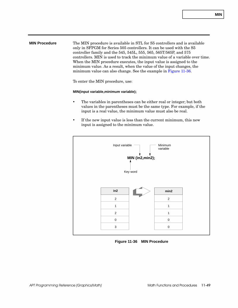
MIN
Math Functions and Procedures 11-49APT Programming Reference (Graphics/Math)
The MIN procedure is available in STL for S5 controllers and is availableonly in SFPGM for Series 505 controllers. It can be used with the S5controller family and the 545, 545L, 555, 565, 565T/565P, and 575controllers. MIN is used to track the minimum value of a variable over time.When the MIN procedure executes, the input value is assigned to theminimum value. As a result, when the value of the input changes, theminimum value can also change. See the example in Figure 11-36.
To enter the MIN procedure, use:
MIN(input variable,minimum variable);
The variables in parentheses can be either real or integer; but bothvalues in the parentheses must be the same type. For example, if theinput is a real value, the minimum value must also be real.
If the new input value is less than the current minimum, this newinput is assigned to the minimum value.
MIN (in2,min2);
Key word
Input variable
in2
1
min2
2
2
0
3
2
1
1
0
0
Minimumvariable
Figure 11-36 MIN Procedure
MIN Procedure
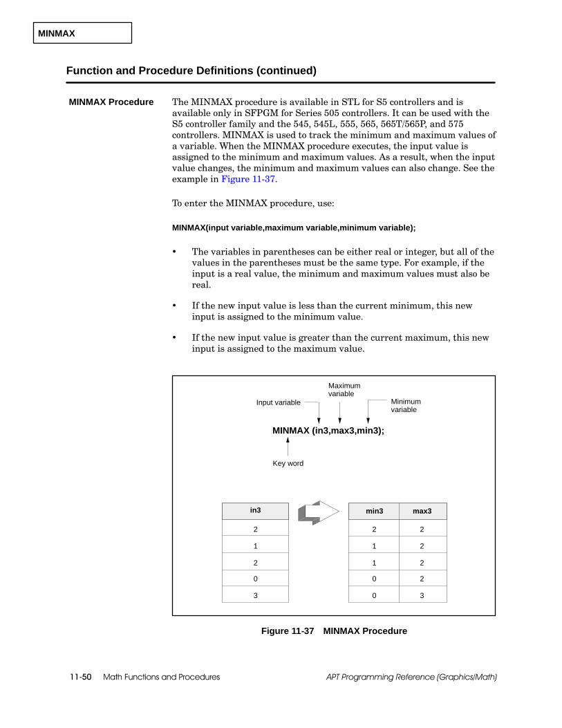
MINMAX
Math Functions and Procedures11-50 APT Programming Reference (Graphics/Math)
Function and Procedure Definitions (continued)
The MINMAX procedure is available in STL for S5 controllers and isavailable only in SFPGM for Series 505 controllers. It can be used with theS5 controller family and the 545, 545L, 555, 565, 565T/565P, and 575controllers. MINMAX is used to track the minimum and maximum values ofa variable. When the MINMAX procedure executes, the input value isassigned to the minimum and maximum values. As a result, when the inputvalue changes, the minimum and maximum values can also change. See theexample in Figure 11-37.
To enter the MINMAX procedure, use:
MINMAX(input variable,maximum variable,minimum variable);
The variables in parentheses can be either real or integer, but all of thevalues in the parentheses must be the same type. For example, if theinput is a real value, the minimum and maximum values must also bereal.
If the new input value is less than the current minimum, this newinput is assigned to the minimum value.
If the new input value is greater than the current maximum, this newinput is assigned to the maximum value.
Key word
Input variable
MINMAX (in3,max3,min3);
in3 min3
1
2
2
0
3
2
1
1
0
0
max3
Minimumvariable
2
2
2
2
3
Maximumvariable
Figure 11-37 MINMAX Procedure
MINMAX Procedure
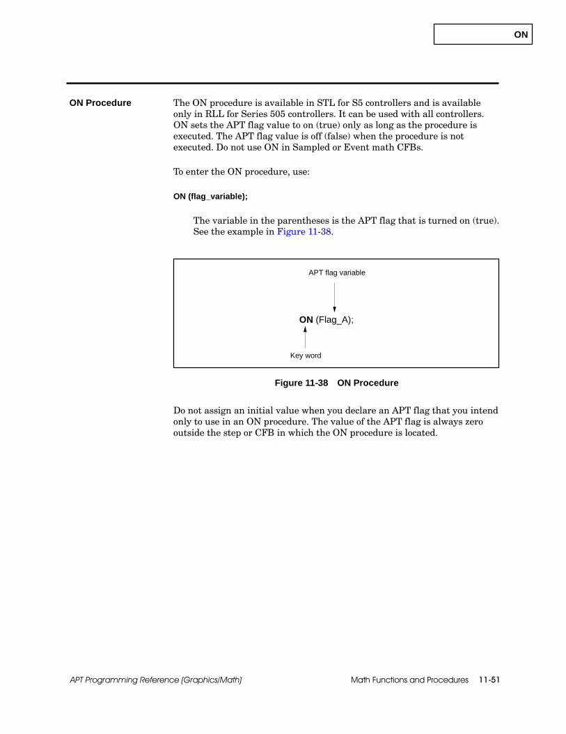
ON
Math Functions and Procedures 11-51APT Programming Reference (Graphics/Math)
The ON procedure is available in STL for S5 controllers and is availableonly in RLL for Series 505 controllers. It can be used with all controllers.ON sets the APT flag value to on (true) only as long as the procedure isexecuted. The APT flag value is off (false) when the procedure is notexecuted. Do not use ON in Sampled or Event math CFBs.
To enter the ON procedure, use:
ON (flag_variable);
The variable in the parentheses is the APT flag that is turned on (true).See the example in Figure 11-38.
Key word
ON (Flag_A);
APT flag variable
Figure 11-38 ON Procedure
Do not assign an initial value when you declare an APT flag that you intendonly to use in an ON procedure. The value of the APT flag is always zerooutside the step or CFB in which the ON procedure is located.
ON Procedure

PACK_BITS
Math Functions and Procedures11-52 APT Programming Reference (Graphics/Math)
Function and Procedure Definitions (continued)
The PACK_BITS procedure is available in STL for S5 controllers and isavailable only in RLL for Series 505 controllers. It can be used with allcontrollers. PACK_BITS shifts the values in a boolean array into an integervariable.
When you define the boolean array for this procedure in the DeclarationTable, the size of the array that you specify determines the number of bitsmoved into the integer variable.
To enter the PACK_BITS procedure, use:
PACK_BITS(variable,variable);
The first variable in parentheses is a boolean array that can contain upto 16 elements. The first element of the array becomes the leastsignificant bit of the integer variable. See the example in Figure 11-39.
The second variable is the integer that receives the elements of theboolean array. All bits in the variable are set to 0 before the values ofthe array are shifted into the integer.
Booleanarrayvariable
PACK_ BITS(binarray,int1);
1 2 3 4 5 6 7 8 9 10 11 13 14 15 1612
0 0 0 0 0 0 1 110 0 0 0 0 00
int1: value = 19
Key word
Integer variable
binarray: size = 6
binarray[1] = 1
binarray[4] = 0
binarray[5] = 1
binarray[3] = 0
binarray[2] = 1
binarray[6] = 0
Leastsignificant bit
Figure 11-39 PACK_BITS Procedure
PACK_BITSProcedure
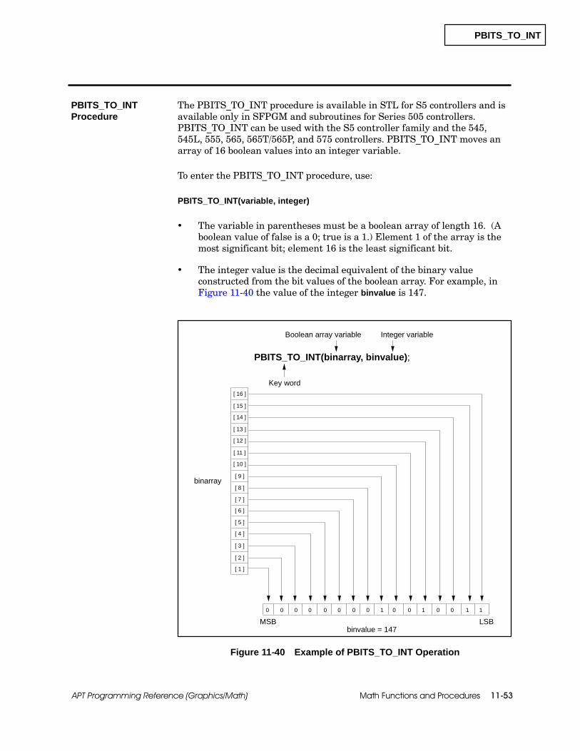
PBITS_TO_INT
Math Functions and Procedures 11-53APT Programming Reference (Graphics/Math)
The PBITS_TO_INT procedure is available in STL for S5 controllers and isavailable only in SFPGM and subroutines for Series 505 controllers.PBITS_TO_INT can be used with the S5 controller family and the 545,545L, 555, 565, 565T/565P, and 575 controllers. PBITS_TO_INT moves anarray of 16 boolean values into an integer variable.
To enter the PBITS_TO_INT procedure, use:
PBITS_TO_INT(variable, integer)
The variable in parentheses must be a boolean array of length 16. (Aboolean value of false is a 0; true is a 1.) Element 1 of the array is themost significant bit; element 16 is the least significant bit.
The integer value is the decimal equivalent of the binary valueconstructed from the bit values of the boolean array. For example, inFigure 11-40 the value of the integer binvalue is 147.
[ 16 ]
[ 15 ]
[ 14 ]
[ 13 ]
[ 12 ]
[ 11 ]
[ 10 ]
[ 9 ]
[ 8 ]
[ 7 ]
[ 6 ]
[ 5 ]
[ 4 ]
[ 3 ]
[ 2 ]
[ 1 ]
1100100100000000
MSB LSB
PBITS_TO_INT(binarray, binvalue);
Key word
Integer variableBoolean array variable
binarray
binvalue = 147
Figure 11-40 Example of PBITS_TO_INT Operation
PBITS_TO_INTProcedure
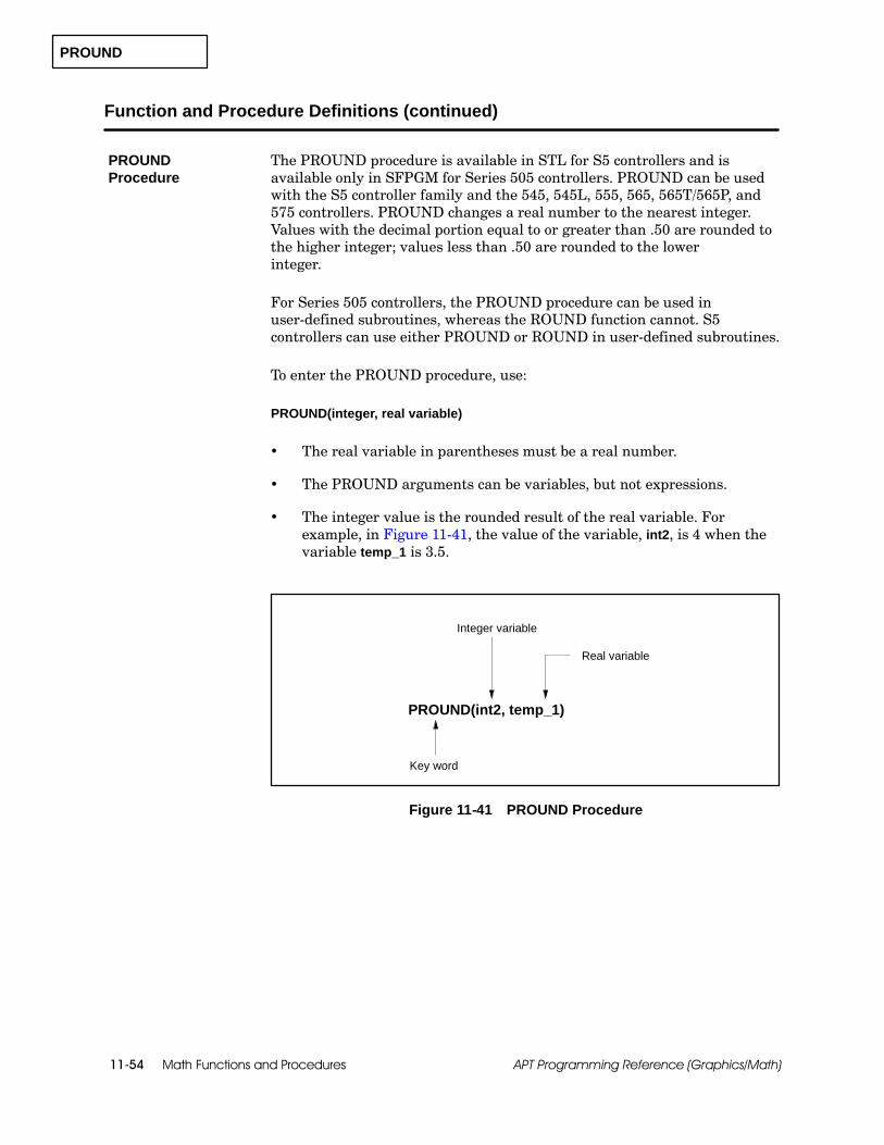
PROUND
Math Functions and Procedures11-54 APT Programming Reference (Graphics/Math)
Function and Procedure Definitions (continued)
The PROUND procedure is available in STL for S5 controllers and isavailable only in SFPGM for Series 505 controllers. PROUND can be usedwith the S5 controller family and the 545, 545L, 555, 565, 565T/565P, and575 controllers. PROUND changes a real number to the nearest integer.Values with the decimal portion equal to or greater than .50 are rounded tothe higher integer; values less than .50 are rounded to the lowerinteger.
For Series 505 controllers, the PROUND procedure can be used inuser-defined subroutines, whereas the ROUND function cannot. S5controllers can use either PROUND or ROUND in user-defined subroutines.
To enter the PROUND procedure, use:
PROUND(integer, real variable)
The real variable in parentheses must be a real number.
The PROUND arguments can be variables, but not expressions.
The integer value is the rounded result of the real variable. Forexample, in Figure 11-41, the value of the variable, int2, is 4 when thevariable temp_1 is 3.5.
Key word
PROUND(int2, temp_1)
Integer variable
Real variable
Figure 11-41 PROUND Procedure
PROUNDProcedure

PTRUNC
Math Functions and Procedures 11-55APT Programming Reference (Graphics/Math)
The PTRUNC procedure is available in STL for S5 controllers and isavailable only in SFPGM for Series 505 controllers. PTRUNC can be usedwith the S5 controller family and the 545, 545L, 555, 565, 565T/565P, and575 controllers. PTRUNC returns the integer portion of the variable inparentheses; that is, it truncates a real number by eliminating its fractionalportion and returning only its integer portion.
For Series 505 controllers, the PTRUNC procedure can be used inuser-defined subroutines, whereas the TRUNC function cannot. S5controllers can use either PTRUNC or TRUNC in user-defined subroutines.
To enter the PTRUNC procedure, use:
PTRUNC(integer, real variable)
The real variable in parentheses must be a real number.
The PTRUNC arguments can be variables, but not expressions.
The returned value is the truncated result of the real variable. Forexample, in Figure 11-42, the value of the variable, int2, is 2 when thevariable temp_1 is 2.718.
Key word
PTRUNC(int2, temp_1)
Integer variable
Real variable
Figure 11-42 PTRUNC Procedure
PTRUNC Procedure
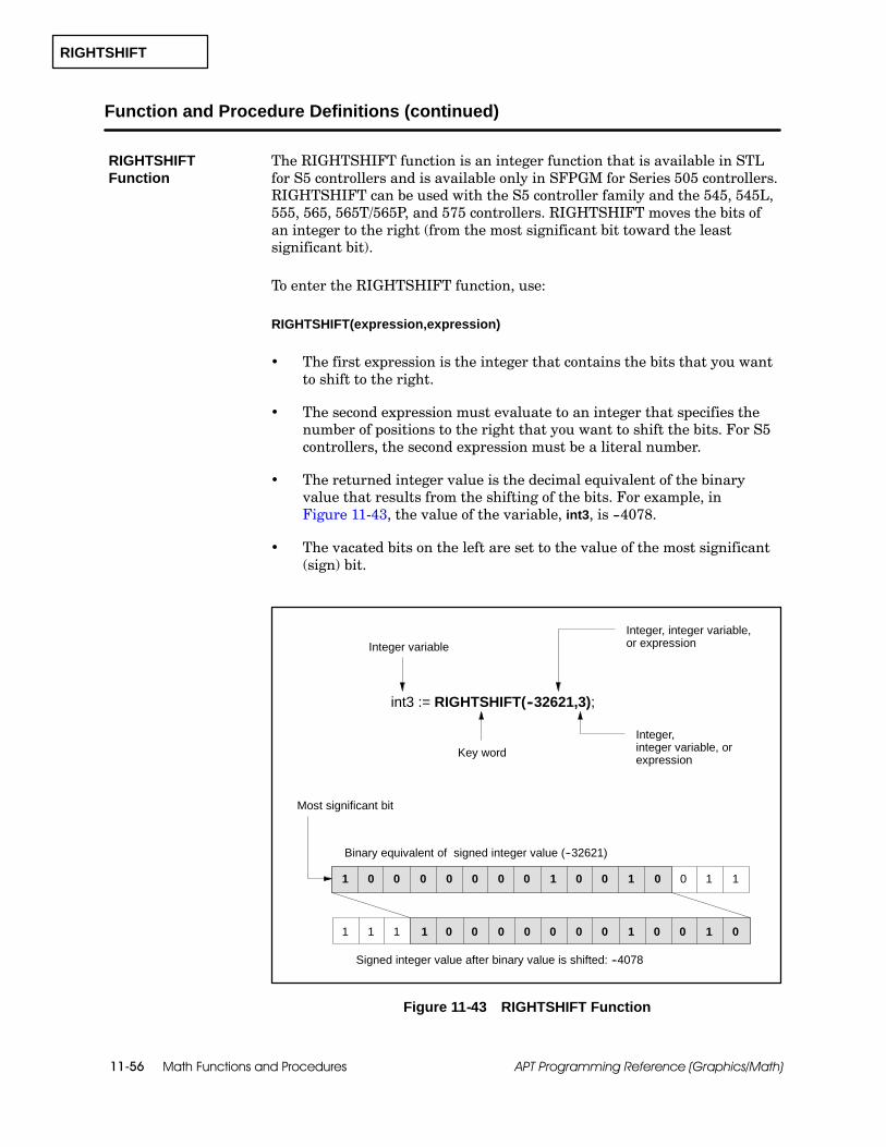
RIGHTSHIFT
Math Functions and Procedures11-56 APT Programming Reference (Graphics/Math)
Function and Procedure Definitions (continued)
The RIGHTSHIFT function is an integer function that is available in STLfor S5 controllers and is available only in SFPGM for Series 505 controllers.RIGHTSHIFT can be used with the S5 controller family and the 545, 545L,555, 565, 565T/565P, and 575 controllers. RIGHTSHIFT moves the bits ofan integer to the right (from the most significant bit toward the leastsignificant bit).
To enter the RIGHTSHIFT function, use:
RIGHTSHIFT(expression,expression)
The first expression is the integer that contains the bits that you wantto shift to the right.
The second expression must evaluate to an integer that specifies thenumber of positions to the right that you want to shift the bits. For S5controllers, the second expression must be a literal number.
The returned integer value is the decimal equivalent of the binaryvalue that results from the shifting of the bits. For example, inFigure 11-43, the value of the variable, int3, is --4078.
The vacated bits on the left are set to the value of the most significant(sign) bit.
Key word
int3 := RIGHTSHIFT(--32621,3);
Integer variable
0 1 0 0 0 1 111 0 0 0 0 00
Most significant bit
Binary equivalent of signed integer value (--32621)
Signed integer value after binary value is shifted: --4078
0 1 0 0 010 0 0 0 001 1 1
Integer, integer variable,or expression
Integer,integer variable, orexpression
0
1
Figure 11-43 RIGHTSHIFT Function
RIGHTSHIFTFunction

ROUND
Math Functions and Procedures 11-57APT Programming Reference (Graphics/Math)
The ROUND function is an integer function that is available in STL for S5controllers and is available only in SFPGM for Series 505 controllers.ROUND can be used with the S5 controller family and the 545, 545L, 555,565, 565T/565P, and 575 controllers. ROUND changes a real number to thenearest integer. Values with the decimal portion equal to or greater than .50are rounded to the higher integer; values less than .50 are rounded to thelower integer.
NOTE: For Series 505 controllers, the ROUND function cannot be used inuser-defined subroutines. Use the PROUND procedure instead. S5controllers can use ROUND function in user-defined subroutines.
To enter the ROUND function, use:
ROUND(expression)
The expression in parentheses must evaluate to a real number.
The returned value is an integer. For example, in Figure 11-44, thevalue of the variable, int2, is 4.
Key word
int2 := ROUND(3.50)
Integer variable
Real number, variable, orexpression
Figure 11-44 ROUND Function
ROUND Function

SCALE
Math Functions and Procedures11-58 APT Programming Reference (Graphics/Math)
Function and Procedure Definitions (continued)
The SCALE procedure is available in STL for S5 controllers and is availableonly in SFPGM for Series 505 controllers. SCALE can be used with the S5controller family and the 545, 545L, 555, 565, 565T/565P, and 575controllers. SCALE converts an integer to a real value between the low andhigh limits that you specify.
The SCALE procedure anticipates an input that has the same format as ananalog input. If you are not scaling an analog input, consider using the scaleCFB.
The integer input can be any one of the following types.
Bipolar The valid range for a Series 505 integer input is --32,000 to32,000. The valid range for an S5 integer input is --2048 to 2048.
Twenty-percent offset The valid range for a Series 505 integer input is6,400 to 32,000. The valid range for an S5 integer input is 512 to 2560.
Zero bias The valid range for a Series 505 integer input is 0 to 32,000.The valid range for an S5 integer input is 0 to 2048.
SCALE Procedure

SCALE
Math Functions and Procedures 11-59APT Programming Reference (Graphics/Math)
Use the following format to enter the SCALE procedure.
SCALE(input variable,output variable,type,low limit,high limit);
The input variable is an integer within the range specified by the type.
The output variable is the real variable that stores the result of theSCALE procedure. See the examples in Figure 11-45 and Figure 11-47.
The type is a character: B (Bipolar), T (Twenty-percent offset), or Z(Zero bias).
The low limit is a real number that specifies the lower boundary of thescaling range.
The high limit is a real number that specifies the upper boundary ofthe scaling range.

SCALE
Math Functions and Procedures11-60 APT Programming Reference (Graphics/Math)
Function and Procedure Definitions (continued)
The operation of the SCALE procedure depends on the type of controller.For a Series 505 controller, SCALE simply takes the input value andconverts it from an integer to a real value. See Figure 11-45.
Key word SCALE(in4,out4,B,0.0,1000.0);
Integer variable Low limit
Real variable Type
High limitReal
numbers
SCALE(in5,out5,T,0.0,1000.0);
Bipolar:out4 = 250.0
SCALE(in6,out6,Z,0.0,1000.0);
20% offset:out5 = 375.0
Zero bias:out6 = 500.0
--16000
16000
16000
SCALE with inputs for a Series 505 controller:
Figure 11-45 SCALE Procedure for Series 505
If you have an S5 controller, the SCALE procedure automatically shifts yourinput value to the right by 3 bits before scaling it from an integer to a real.This shifting occurs because S5 analog inputs are 16-bit numbers, with 12bits of resolution, and the 3 least significant bits contain error information.Figure 11-46 shows the bit shift that is performed before your value isscaled.
0 1 0 0 11 0 0 0 0 00
Most significant bit
0 1 0 0 010 0 0 0 000 0 0
0
1
215214 213 212 211 210 29 28 27 26 25 24 23 22 21 20
215214 213 212 211 210 29 28 27 26 25 24 23 22 21 20
Single ScanBroken Transmitter
Overflow
¦ 16384
¦ 2048
Raw input value
Shifted input value
For S5 controllers, the SCALE procedure shifts your input three bits to the right.
Figure 11-46 S5 Analog I/O Bit Shift
Using SCALE for aSeries 505Controller
Using SCALE foran S5 Controller

SCALE
Math Functions and Procedures 11-61APT Programming Reference (Graphics/Math)
If you want to scale something other than an analog input, you mustcompensate for the bit shift that is automatically performed when you usethe SCALE procedure. Either use the scale CFB instead, since the CFB doesnot perform a bit shift, or else multiply your input value by 8 before you usethe SCALE procedure. Do not use the LEFTSHIFT procedure; you lose thesign bit Figure 11-47 shows how to use the SCALE procedure for differenttypes of input values if you have an S5 controller.
SCALE(in4,out4,B,0.0,1000.0);
Integer variable Low limit
Real variable Type
High limitReal
numbers
SCALE(in5,out5,T,0.0,1000.0);
Bipolar:out4 = 250.0
SCALE(in6,out6,Z,0.0,1000.0); Zero bias:out6 = 500.0
--1024 x 8 = --8192
1024 x 8 = 8192
1024 x 8 = 8192
20% offset:out5 = 250.0
Key word
Scaling an input value that is not analog.Multiply input by 8 before performing SCALE.
SCALE(in4,out4,B,0.0,1000.0);
Integer variable Low limit
Real variable Type
High limitReal
numbers
SCALE(in5,out5,T,0.0,1000.0);
Bipolar:out4 = 250.0
SCALE(in6,out6,Z,0.0,1000.0); Zero bias:out6 = 500.0
--1024
1024
1024
20% offset:out5 = 250.0
Key word
Scaling an analog input value for an S5 controller.
Figure 11-47 SCALE Procedure for S5
NOTE: If you test the SCALE procedure using AI.RAW, you must multiplyyour input value by 8 before you send it to SCALE. However, if you sendAI.RAW to SCALE from an S5 analog input card, the input does not need tobe multiplied in order to be read correctly by SCALE.
Compensating forthe Bit Shift(S5 only)
SETSSI
Math Functions and Procedures11-62 APT Programming Reference (Graphics/Math)
Function and Procedure Definitions (continued)
The SETSSI procedure is not supported for S5 controllers; it is availableonly in RLL for Series 505 controllers. It can be used only with the560/560T/565/565T/565P controllers. SETSSI sets or resets the 560scan-inhibit bit in Status Word 1, shown in Figure 11-48. This procedureallows you to control the synchronization of an active controller with astandby controller. See the SIMATIC TI505 Programming ReferenceManual for additional information about this procedure.
NOTE: The SETSSI procedure is not available on all controllers.
To enter the SETSSI procedure, use:
SETSSI(boolean expression);
If the boolean expression is true, the scan-inhibit bit is set to 1 andinhibits synchronization.
If the boolean expression is false, the scan-inhibit bit is reset to 0 andallows synchronization.
SETSSI Procedure
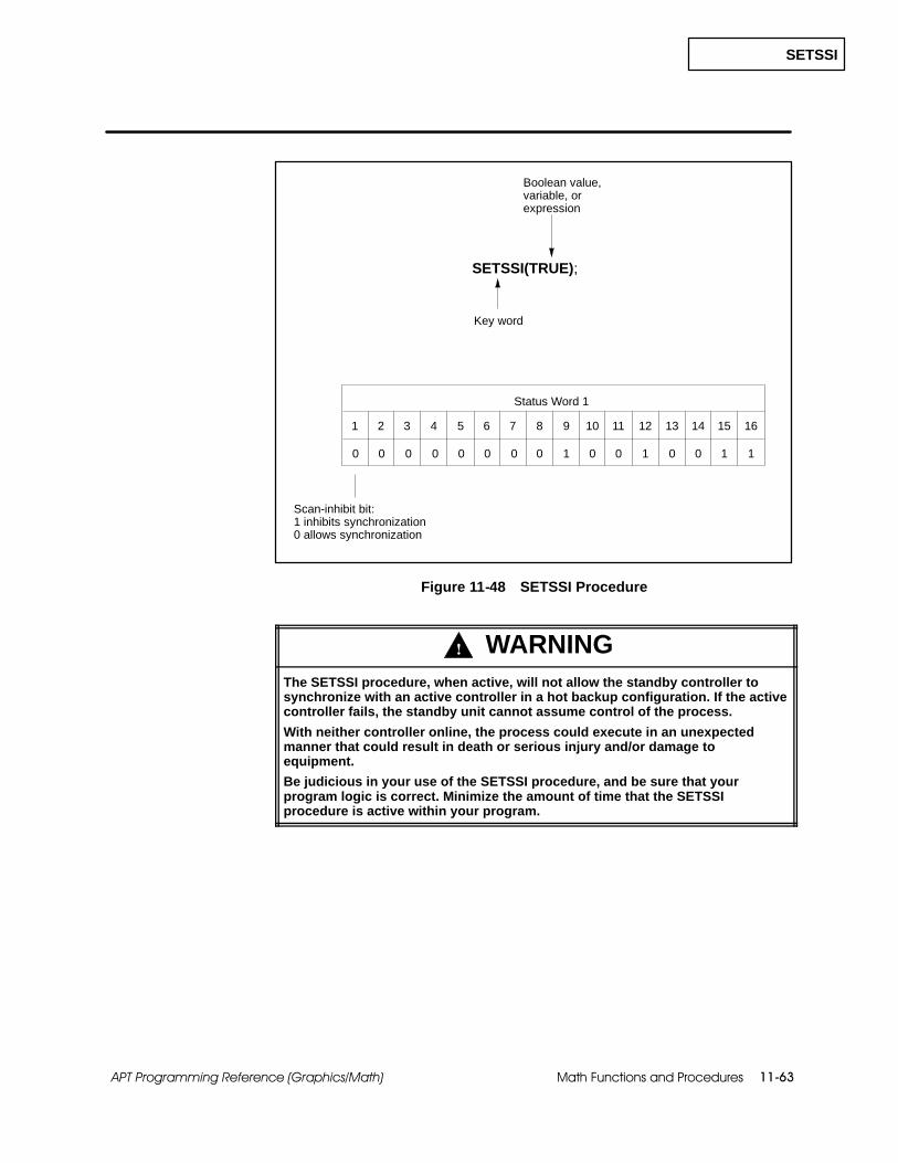
SETSSI
Math Functions and Procedures 11-63APT Programming Reference (Graphics/Math)
SETSSI(TRUE);
1 2 3 4 5 6 7 8 9 10 11 13 14 15 1612
0 1 0 0 0 0 1 110 0 0 0 0 00
Status Word 1
Scan-inhibit bit:1 inhibits synchronization0 allows synchronization
Key word
Boolean value,variable, orexpression
Figure 11-48 SETSSI Procedure
! WARNINGThe SETSSI procedure, when active, will not allow the standby controller tosynchronize with an active controller in a hot backup configuration. If the activecontroller fails, the standby unit cannot assume control of the process.
With neither controller online, the process could execute in an unexpectedmanner that could result in death or serious injury and/or damage toequipment.
Be judicious in your use of the SETSSI procedure, and be sure that yourprogram logic is correct. Minimize the amount of time that the SETSSIprocedure is active within your program.

SIN
Math Functions and Procedures11-64 APT Programming Reference (Graphics/Math)
Function and Procedure Definitions (continued)
The SIN function is a real function that is available in STL for S5controllers and is available only in SFPGM for Series 505 controllers. SINcan be used with the S5 controller family and the 545, 545L, 555, 565,565T/565P, and 575 controllers. SIN returns the sine of the expression inparentheses.
To enter the SIN function, use:
SIN(expression)
The expression in parentheses must evaluate to a real number thatrepresents the measure of an angle in radians.
For S5 controllers, the expression cannot evaluate to a negativenumber, and it must represent radians in the range 0--2↓.
The returned value is also a real number between --1 and 1. Forexample, in Figure 11-49, the value of the variable, angle1, is 0.50.
Real variable
Key word
angle1 := SIN(30.0 * 3.14159 / 180.0);
Real number, variable, orexpression that representsan angle in radians
Figure 11-49 SIN Function
SIN Function

SQRT
Math Functions and Procedures 11-65APT Programming Reference (Graphics/Math)
The SQRT function is a real function that is available in STL for S5controllers and is available only in SFPGM for Series 505 controllers. SQRTcan be used with the S5 controller family and the 545, 545L, 555, 565,565T/565P, and 575 controllers. SQRT returns the square root of theexpression in parentheses.
To enter the SQRT function, use:
SQRT(expression)
The expression in parentheses must evaluate to a positive real number.
The returned value is also a real number. For example, inFigure 11-50, the value of the variable, real1, is 12.0.
Key word
real1 := SQRT(144.0)
Real variable
Real number, variable,or expression
Figure 11-50 SQRT Function
SQRT Function

TAN
Math Functions and Procedures11-66 APT Programming Reference (Graphics/Math)
Function and Procedure Definitions (continued)
The TAN function is a real function that is available in STL for S5controllers and is available only in SFPGM for Series 505 controllers. TANcan be used with the S5 controller family and the 545, 545L, 555, 565,565T/565P, and 575 controllers. TAN returns the tangent of the expressionin parentheses.
To enter the TAN function, use:
TAN(expression)
The expression in parentheses must evaluate to a real number thatrepresents the measure of an angle in radians.
For S5 controllers, the expression cannot evaluate to a negativenumber, and it must represent radians in the range 0--2↓.
The returned value is also a real number. For example, in Figure 11-51,the value of the variable, angle1, is 1.0.
Key word
angle1 := TAN(45.0 * 3.14159 / 180.0);
Real variable
Real number, variable, orexpression that representsan angle in radians
Figure 11-51 TAN Function
TAN Function
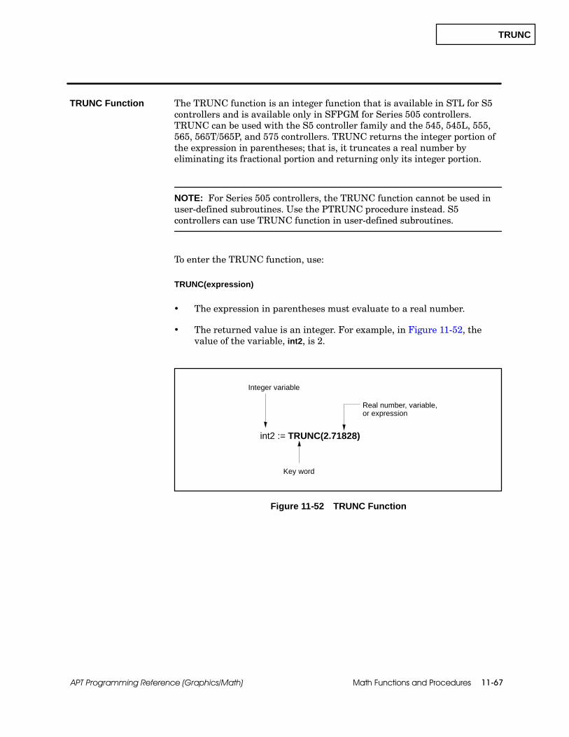
TRUNC
Math Functions and Procedures 11-67APT Programming Reference (Graphics/Math)
The TRUNC function is an integer function that is available in STL for S5controllers and is available only in SFPGM for Series 505 controllers.TRUNC can be used with the S5 controller family and the 545, 545L, 555,565, 565T/565P, and 575 controllers. TRUNC returns the integer portion ofthe expression in parentheses; that is, it truncates a real number byeliminating its fractional portion and returning only its integer portion.
NOTE: For Series 505 controllers, the TRUNC function cannot be used inuser-defined subroutines. Use the PTRUNC procedure instead. S5controllers can use TRUNC function in user-defined subroutines.
To enter the TRUNC function, use:
TRUNC(expression)
The expression in parentheses must evaluate to a real number.
The returned value is an integer. For example, in Figure 11-52, thevalue of the variable, int2, is 2.
Key word
int2 := TRUNC(2.71828)
Integer variable
Real number, variable,or expression
Figure 11-52 TRUNC Function
TRUNC Function
UNPACK_BITS
Math Functions and Procedures11-68 APT Programming Reference (Graphics/Math)
Function and Procedure Definitions (continued)
The UNPACK_BITS procedure is available in STL for S5 controllers and isavailable only in RLL for Series 505 controllers. It can be used with allcontrollers.
When you define the boolean array for this procedure in the DeclarationTable, the size of the array that you specify determines the number of bitsthat are moved from the integer variable.
To enter the UNPACK_BITS procedure, use:
UNPACK_BITS(variable,variable);
The first variable is a boolean array that can contain up to 16 elements.The least significant bit becomes element 1 of the array. See theexample in Figure 11-53.
The second variable is the integer that contains the bits to be moved.
UNPACK_BITSProcedure

UNPACK_BITS
Math Functions and Procedures 11-69APT Programming Reference (Graphics/Math)
Figure 11-53 shows how UNPACK_BITS shifts a specified number of bitsfrom an integer into a boolean array.
UNPACK_ BITS(binarray,int2);
1 2 3 4 5 6 7 8 9 10 11 13 14 15 1612
0 0 0 0 0 0 1 110 0 0 0 0 00
int2: value = 19
Key word
Integer variable
Boolean arrayvariable
binarray: size = 6
binarray[1] = 1
binarray[5] = 1
binarray[4] = 0
binarray[3] = 0
binarray[2] = 1
binarray[6] = 0
Leastsignificant bit
Figure 11-53 UNPACK_BITS Procedure

UNSCALE
Math Functions and Procedures11-70 APT Programming Reference (Graphics/Math)
Function and Procedure Definitions (continued)
The UNSCALE procedure is available in STL for S5 controllers and isavailable only in SFPGM for Series 505 controllers. UNSCALE can be usedwith the S5 controller family and the 545, 545L, 555, 565, 565T/565P, and575 controllers. UNSCALE converts a real value, one that falls withinspecified low and high limits, to a scaled integer. The scaled integer outputcan be any one of the following types.
Bipolar For a Series 505 controller, bipolar unscales the real value to aninteger between --32,000 and 32,000. For an S5 controller, bipolar unscalesthe real value to an integer between --1024 and 1024.
Twenty-percent offset For a Series 505 controller, twenty-percent offsetunscales the real value to an integer between 6,400 and 32,000. This type isnot available for S5 controllers.
Zero bias For a Series 505 controller, zero bias unscales the real value toan integer between 0 and 32,000. For an S5 controller, zero bias unscalesthe real value to an integer between 0 and 1024.
NOTE: If your S5 analog output module has a built-in twenty-percentoffset, you must select zero bias for UNSCALE. If your S5 analog outputmodule does not have a twenty-percent offset built in, you can choosebetween zero bias and bipolar; you still cannot use twenty-percent offsetwith UNSCALE.
To enter the UNSCALE procedure, use:
UNSCALE(input variable,output variable,type,low limit,high limit);
The input variable is a real value within the range specified by the lowand high limits.
The output variable is the integer variable that stores the result of theUNSCALE procedure.
The type is a character: B (Bipolar), T (Twenty-percent offset), orZ (Zero bias).
The low limit is a real number that specifies the lower boundary of thescaling range.
The high limit is a real number that specifies the upper boundary ofthe scaling range.
UNSCALEProcedure
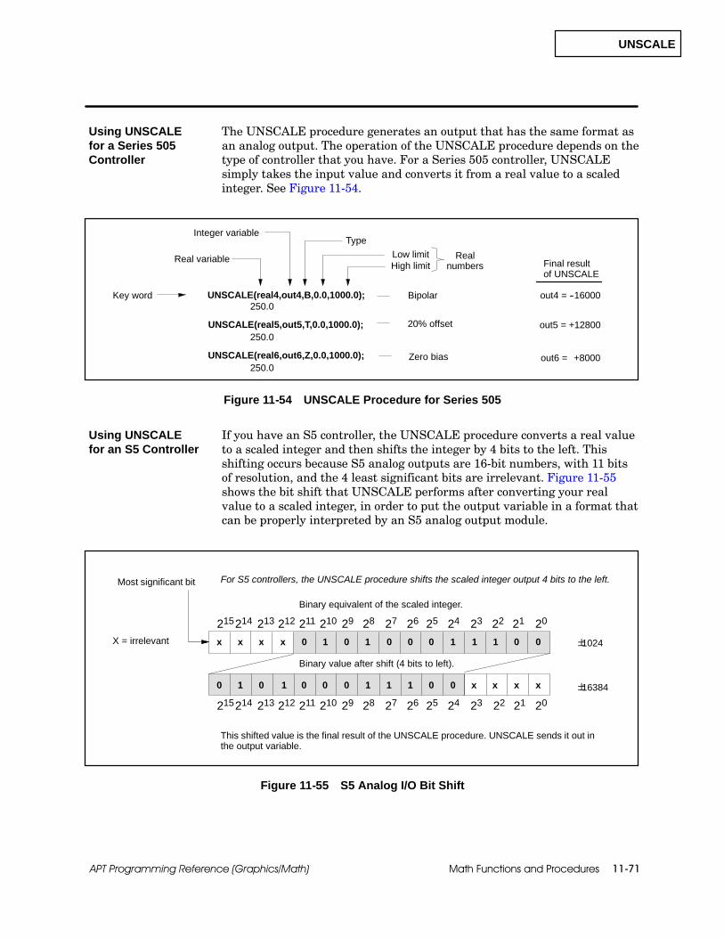
UNSCALE
Math Functions and Procedures 11-71APT Programming Reference (Graphics/Math)
The UNSCALE procedure generates an output that has the same format asan analog output. The operation of the UNSCALE procedure depends on thetype of controller that you have. For a Series 505 controller, UNSCALEsimply takes the input value and converts it from a real value to a scaledinteger. See Figure 11-54.
out6 = +8000
Key word UNSCALE(real4,out4,B,0.0,1000.0);
Integer variable
Low limitReal variable
Type
High limitReal
numbers
UNSCALE(real5,out5,T,0.0,1000.0);
Bipolar
UNSCALE(real6,out6,Z,0.0,1000.0); Zero bias
250.0out4 =
out5 =20% offset
--16000
250.0
250.0
+12800
Final resultof UNSCALE
Figure 11-54 UNSCALE Procedure for Series 505
If you have an S5 controller, the UNSCALE procedure converts a real valueto a scaled integer and then shifts the integer by 4 bits to the left. Thisshifting occurs because S5 analog outputs are 16-bit numbers, with 11 bitsof resolution, and the 4 least significant bits are irrelevant. Figure 11-55shows the bit shift that UNSCALE performs after converting your realvalue to a scaled integer, in order to put the output variable in a format thatcan be properly interpreted by an S5 analog output module.
x 0 0x x x 1 0 0 0 1 011 0 1
0 0 x x xx0 0 1 1 100 1 0 1
Most significant bit
215214 213 212 211 210 29 28 27 26 25 24 23 22 21 20
215214 213 212 211 210 29 28 27 26 25 24 23 20
á1024
á16384
2122
X = irrelevant
Binary equivalent of the scaled integer.
This shifted value is the final result of the UNSCALE procedure. UNSCALE sends it out inthe output variable.
For S5 controllers, the UNSCALE procedure shifts the scaled integer output 4 bits to the left.
Binary value after shift (4 bits to left).
Figure 11-55 S5 Analog I/O Bit Shift
Using UNSCALEfor a Series 505Controller
Using UNSCALEfor an S5 Controller
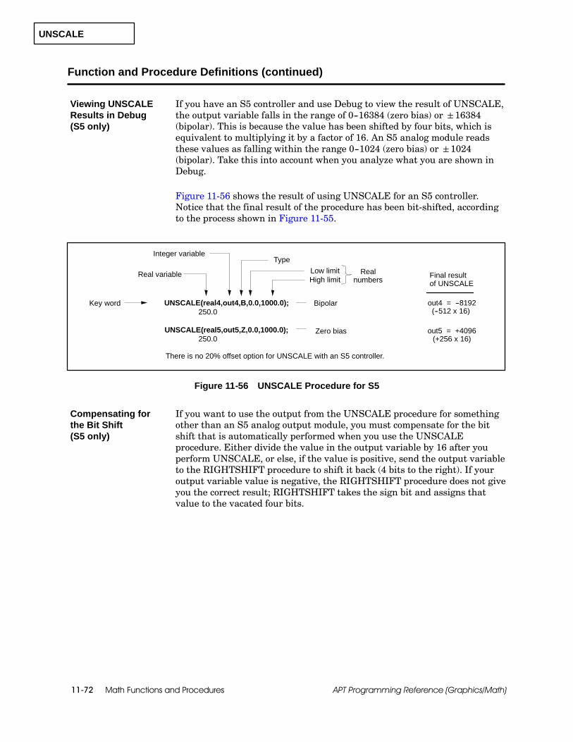
UNSCALE
Math Functions and Procedures11-72 APT Programming Reference (Graphics/Math)
Function and Procedure Definitions (continued)
If you have an S5 controller and use Debug to view the result of UNSCALE,the output variable falls in the range of 0--16384 (zero bias) orá16384(bipolar). This is because the value has been shifted by four bits, which isequivalent to multiplying it by a factor of 16. An S5 analog module readsthese values as falling within the range 0--1024 (zero bias) orá1024(bipolar). Take this into account when you analyze what you are shown inDebug.
Figure 11-56 shows the result of using UNSCALE for an S5 controller.Notice that the final result of the procedure has been bit-shifted, accordingto the process shown in Figure 11-55.
Key word UNSCALE(real4,out4,B,0.0,1000.0);
Integer variable
Low limitReal variable
Type
High limitReal
numbers
Bipolar
UNSCALE(real5,out5,Z,0.0,1000.0); Zero bias
250.0out4 = --8192
out5 = +4096
There is no 20% offset option for UNSCALE with an S5 controller.
(--512 x 16)
(+256 x 16)250.0
Final resultof UNSCALE
Figure 11-56 UNSCALE Procedure for S5
If you want to use the output from the UNSCALE procedure for somethingother than an S5 analog output module, you must compensate for the bitshift that is automatically performed when you use the UNSCALEprocedure. Either divide the value in the output variable by 16 after youperform UNSCALE, or else, if the value is positive, send the output variableto the RIGHTSHIFT procedure to shift it back (4 bits to the right). If youroutput variable value is negative, the RIGHTSHIFT procedure does not giveyou the correct result; RIGHTSHIFT takes the sign bit and assigns thatvalue to the vacated four bits.
Viewing UNSCALEResults in Debug(S5 only)
Compensating forthe Bit Shift(S5 only)

Sequential Function Charts 12-1APT Programming Reference (Graphics/Math)
Chapter 12
Sequential Function Charts
12.1 Understanding Sequential Function Charts 12-2. . . . . . . . . . . . . . . . . . . . . . . . . . . . . . . . . . . . . . .Overview 12-2. . . . . . . . . . . . . . . . . . . . . . . . . . . . . . . . . . . . . . . . . . . . . . . . . . . . . . . . . . . . . . . . . . . . . . .Program Flow 12-3. . . . . . . . . . . . . . . . . . . . . . . . . . . . . . . . . . . . . . . . . . . . . . . . . . . . . . . . . . . . . . . . . . .SFC Scope 12-4. . . . . . . . . . . . . . . . . . . . . . . . . . . . . . . . . . . . . . . . . . . . . . . . . . . . . . . . . . . . . . . . . . . . .
12.2 Steps 12-5. . . . . . . . . . . . . . . . . . . . . . . . . . . . . . . . . . . . . . . . . . . . . . . . . . . . . . . . . . . . . . . . . . . . . . . . .Overview 12-5. . . . . . . . . . . . . . . . . . . . . . . . . . . . . . . . . . . . . . . . . . . . . . . . . . . . . . . . . . . . . . . . . . . . . . .Types 12-5. . . . . . . . . . . . . . . . . . . . . . . . . . . . . . . . . . . . . . . . . . . . . . . . . . . . . . . . . . . . . . . . . . . . . . . . . .Sections 12-6. . . . . . . . . . . . . . . . . . . . . . . . . . . . . . . . . . . . . . . . . . . . . . . . . . . . . . . . . . . . . . . . . . . . . . .
12.3 Transitions 12-8. . . . . . . . . . . . . . . . . . . . . . . . . . . . . . . . . . . . . . . . . . . . . . . . . . . . . . . . . . . . . . . . . . . .Overview 12-8. . . . . . . . . . . . . . . . . . . . . . . . . . . . . . . . . . . . . . . . . . . . . . . . . . . . . . . . . . . . . . . . . . . . . . .Evaluation 12-10. . . . . . . . . . . . . . . . . . . . . . . . . . . . . . . . . . . . . . . . . . . . . . . . . . . . . . . . . . . . . . . . . . . . . .
12.4 Step/Transition Rules 12-12. . . . . . . . . . . . . . . . . . . . . . . . . . . . . . . . . . . . . . . . . . . . . . . . . . . . . . . . . . .Initial and End Steps 12-12. . . . . . . . . . . . . . . . . . . . . . . . . . . . . . . . . . . . . . . . . . . . . . . . . . . . . . . . . . . . .Steps and Transitions 12-13. . . . . . . . . . . . . . . . . . . . . . . . . . . . . . . . . . . . . . . . . . . . . . . . . . . . . . . . . . . .
12.5 Lines, Arrows, and Graphic Connections 12-14. . . . . . . . . . . . . . . . . . . . . . . . . . . . . . . . . . . . . . . . .Lines 12-14. . . . . . . . . . . . . . . . . . . . . . . . . . . . . . . . . . . . . . . . . . . . . . . . . . . . . . . . . . . . . . . . . . . . . . . . . .Arrows 12-15. . . . . . . . . . . . . . . . . . . . . . . . . . . . . . . . . . . . . . . . . . . . . . . . . . . . . . . . . . . . . . . . . . . . . . . . .Graphic Connections 12-16. . . . . . . . . . . . . . . . . . . . . . . . . . . . . . . . . . . . . . . . . . . . . . . . . . . . . . . . . . . .
12.6 Parallel Branches 12-17. . . . . . . . . . . . . . . . . . . . . . . . . . . . . . . . . . . . . . . . . . . . . . . . . . . . . . . . . . . . . .Parallel Branching 12-17. . . . . . . . . . . . . . . . . . . . . . . . . . . . . . . . . . . . . . . . . . . . . . . . . . . . . . . . . . . . . . .Parallel Branching Rules 12-20. . . . . . . . . . . . . . . . . . . . . . . . . . . . . . . . . . . . . . . . . . . . . . . . . . . . . . . . .
12.7 Selection Branches 12-22. . . . . . . . . . . . . . . . . . . . . . . . . . . . . . . . . . . . . . . . . . . . . . . . . . . . . . . . . . . . .Selection Branching 12-22. . . . . . . . . . . . . . . . . . . . . . . . . . . . . . . . . . . . . . . . . . . . . . . . . . . . . . . . . . . . .Selection Branching Rules 12-25. . . . . . . . . . . . . . . . . . . . . . . . . . . . . . . . . . . . . . . . . . . . . . . . . . . . . . . .
12.8 Main and Subordinate SFCs 12-28. . . . . . . . . . . . . . . . . . . . . . . . . . . . . . . . . . . . . . . . . . . . . . . . . . . . .Main SFC 12-28. . . . . . . . . . . . . . . . . . . . . . . . . . . . . . . . . . . . . . . . . . . . . . . . . . . . . . . . . . . . . . . . . . . . . .Subordinate SFCs 12-29. . . . . . . . . . . . . . . . . . . . . . . . . . . . . . . . . . . . . . . . . . . . . . . . . . . . . . . . . . . . . . .

Sequential Function Charts12-2 APT Programming Reference (Graphics/Math)
12.1 Understanding Sequential Function Charts
As part of the process of developing an APT program, you create a structurethat specifies the sequence of events in your control process. This structureis called a Sequential Function Chart (SFC).
An SFC is a graphical representation of a state-oriented (or step-oriented)control process. The SFC Editor provides a collection of graphics tools, texteditors, and programming languages that you use to represent a controlprocess as an SFC.
APT recognizes three types of SFCs.
The main SFC starts the execution of program logic for a unit. Eachunit has only one main SFC. You can designate any SFC as the mainSFC by using the Promote option.
A subordinate SFC executes its processing only when “called” byanother SFC. You can nest any number of subordinate SFCs in a unit.
A safe-state SFC executes when triggered by a specified event, such asan equipment failure. The safe-state SFC stops the processing of eitherall other SFCs in the currently active unit, or just a single SFC. Whenthe safe-state SFC completes execution, control is transferred toanother SFC, returning the program to some point in the normalprocess.
In general terms, an SFC consists of steps and transitions that can bearranged in a simple sequence or in branches.
Each step contains program statements that represent a stage in thesolution of a problem. Each step must be separated from the next stepby one and only one transition.
Each transition contains one conditional expression that determineswhen program control passes from one step to the next.
Parallel branches allow you to follow a single transition with more thanone step.
Selection branches allow you to follow a single step with more than onetransition condition.
Steps and transitions can contain comments to document your sequence ofcontrol. See Section 10.6 in Chapter 10 for information about usingcomments in your program.
Overview

Sequential Function Charts 12-3APT Programming Reference (Graphics/Math)
Program control within an SFC flows from the top of the chart toward thebottom. Figure 12-1 illustrates how the step/transition structure controlsprogram flow. When program control enters Step 1, that step is consideredactive. The statements in Step 1 execute at least once and continueexecuting until the expression in Transition 1 becomes true. At that time,Step 1 becomes inactive; and the statements in that step stop executing.Program control then passes through the transition to activate Step 2.
Step 1
Transition 1
Step 2
FALSE
ACTIVE
inactive
Step 1
Transition 1
Step 2
TRUE
inactive
ACTIVE
Step 1 is ACTIVE: statements execute atleast once and continue executing untilTransition 1 becomes TRUE.
Step 2 becomes ACTIVE; statementsexecute at least once and continueexecuting until next transition is TRUE.
Expression inTransition 1becomes TRUE.
Figure 12-1 Program Flow through Steps and Transitions
When a program is first downloaded to the controller, all .ENABL extensionvariables are set to true. The first step in each main SFC is automaticallyactivated when the controller goes into run mode.
You can control the operation of any SFC by toggling the .ENABL extensionof the unit or program. If the prog_name.ENABL bit is true and you set it tofalse, all SFCs are turned off and all devices are set to an unlocked state(manual mode). When you set the prog_name.ENABL bit back to true, thefirst step of the main SFC is activated. All devices can then be placed in thelocked state (automatic mode) with the appropriate command or assignmentstatement. The unit_name.ENABL extension works similarly for unit SFCsand devices.
The prog_name.ABORT extension variable allows you to stop program SFCexecution by setting it to true. To restart the program, set the .ABORTextension back to false and then toggle the .ENABL extension as explainedabove. The unit_name.ABORT extension works similarly for unit SFCs.
Program Flow

Sequential Function Charts12-4 APT Programming Reference (Graphics/Math)
Understanding Sequential Function Charts (continued)
If the controller loses power, all units become inactive and remain inactiveuntil the power returns. When power returns, each unit and/or programstarts up in the initial step of the main SFC. One exception to this case issafe-state SFCs. If a retentive safe-state SFC was armed before the powerfailure and its trigger becomes true after the power returns, the safe-stateactivates and re-enables the unit. Chapter 13 of this manual contains thedetails about safe-state SFCs.
! WARNINGIf you have an S5 controller, some or all of your program variables, steptransition expressions, and safe-state triggers can retain their value upon areturn from power failure. This could cause unexpected program behavior,because SFC steps or safe-states could become active.
Unexpected program behavior can cause death or injury to personnel, and/ordamage to equipment.
Carefully consider what happens to your program variables, step transitionexpressions, and safe-state triggers during power failure. The way you handleyour operating system defaults determines whether some memory is retentiveor not. Do not leave a variable set to true if that value could jeopardize programoperation upon return from a power failure. See the chapter called “Compilingan APT Program” in the SIMATIC APT User Manual more information aboutsetting operating system defaults.
Like CFCs, SFCs are available at both the Unit Content Level and at theProgram Content Level. The availability of SFCs at the Unit Content Levelallows you to establish and maintain independent control of each unit. SFCsat the Program Content Level allow high-level sequence control across unitboundaries.
You can create any number of SFCs at both the Program Content and UnitContent levels. However, if you have a Series 505 controller and want to usethe Step Logger option in the Debug Utility, you cannot have more than 64SFCs in a unit. (Step Logger is not currently supported for S5.) One SFCcan call a subordinate SFC only if both SFCs are in the same unit.
SFCs in the same unit can also communicate with each other throughvariables and objects residing at the Program Content Level or at the UnitContent Level for that unit. SFCs residing in different units cancommunicate with each other only through variables and objects residing atthe Program Content Level. An SFC in a unit cannot access a subordinateSFC or safe-state SFC in another unit or at the global level. Global SFCscannot access subordinate or safe-state SFCs that are defined in units.
SFC Scope

Sequential Function Charts 12-5APT Programming Reference (Graphics/Math)
12.2 Steps
Each step in an SFC can contain one or more commands that represent astage in the solution of a problem. A step is entered from the top and exitedfrom the bottom. An SFC can contain from 2 to 500 steps. APTautomatically numbers each step with a unique label from S1 to S500.
Figure 12-2 shows the three types of steps: initial, end, and regular.
Initial Step Regular StepEnd Step
Figure 12-2 Types of Steps
The initial step is the step that is activated when an SFC is enabled. EachSFC must contain one and only one initial step.
The end step specifies the actions that occur when the execution of an SFCis complete. There can be no steps or transitions following an end step. Anactive end step remains active until the SFC is disabled or aborted. An SFCcan have more than one end step.
A regular step is any step that is neither an initial step nor an end step.
Overview
Types
Sequential Function Charts12-6 APT Programming Reference (Graphics/Math)
Steps (continued)
The statements within a step can be divided into two sections: the parallelsection and the math section. A step can include a parallel section, a mathsection, both, or neither. (You can create a step that does not include anystatements). If a step includes both a parallel section and a math section,the parallel section must precede the math section.
The parallel section of a step contains statements that executesimultaneously (“in parallel”), regardless of the order in which they appear.The continuous execution of these statements continues as long as the stepis active.
Statements in the parallel section can be commands with the format:
command object;
The commands used with individual APT objects are listed with theexplanation of each object. For example, see the chapter on devices foran explanation of device commands.
Statements in the parallel section can be simple assignmentstatements, or boolean expressions that do not contain arithmeticoperations or functions. The assignment statement has the format:
identifier := identifier;
Both identifiers are the same type of value (real, integer, boolean,array, etc.). These identifiers can be extension variables that arecreated by the system, names that were defined in the “APTDeclarations” chapter in the SIMATIC APT Programming Reference(Tables) Manual, or numerical values.
The boolean expression has the following format:
boolean identifier: = boolean expression;
The following is an example of a boolean expression:
Bool: = Bool1 or Bool2 and Real1>Real2;
NOTE: The objects referenced by the commands are located elsewhere inthe STL or RLL code. Objects do not process the command until the objectcode executes.
Sections

Sequential Function Charts 12-7APT Programming Reference (Graphics/Math)
The math section of a step consists of Math Language statements thatexecute sequentially, in the order in which they appear. The sequentialexecution of these statements continues as long as the step is active.
The word MATH marks the end of the parallel section and indicatesthat the remainder of the step is a math section.
The statements that follow a MATH statement constitute the mathsection of a step. The Math Language statements are described inChapter 10, “Math Language Overview,” and Chapter 11, “MathLanguage Functions and Procedures.”
Math statements can be commands that have the format:
command object;
The commands that can be used with individual APT objects are listedwith the explanation of each object. For example, see the chapter ondevices for an explanation of device commands.
Figure 12-3 illustrates a step that includes both a parallel section and amath section.
BEGINz := x -- y * ratio;target := wt210 -- Z;START b12;
pit101.HHA := 24.7;START a101;AUTO tic101;
ParallelSection
MathSection
“Math” Statement marksend of parallel section andbeginning of math section
MATH
S3
Figure 12-3 Sections of a Step
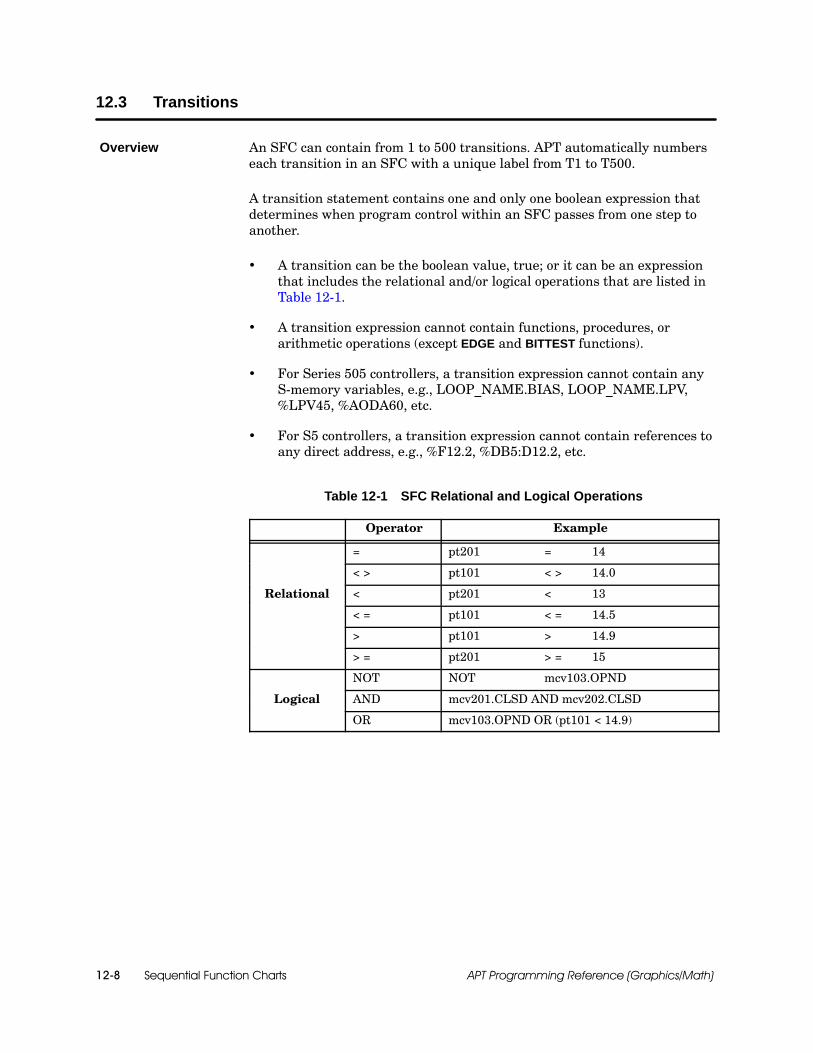
Sequential Function Charts12-8 APT Programming Reference (Graphics/Math)
12.3 Transitions
An SFC can contain from 1 to 500 transitions. APT automatically numberseach transition in an SFC with a unique label from T1 to T500.
A transition statement contains one and only one boolean expression thatdetermines when program control within an SFC passes from one step toanother.
A transition can be the boolean value, true; or it can be an expressionthat includes the relational and/or logical operations that are listed inTable 12-1.
A transition expression cannot contain functions, procedures, orarithmetic operations (except EDGE and BITTEST functions).
For Series 505 controllers, a transition expression cannot contain anyS-memory variables, e.g., LOOP_NAME.BIAS, LOOP_NAME.LPV,%LPV45, %AODA60, etc.
For S5 controllers, a transition expression cannot contain references toany direct address, e.g., %F12.2, %DB5:D12.2, etc.
Table 12-1 SFC Relational and Logical Operations
Operator Example
= pt201 = 14
< > pt101 < > 14.0
Relational < pt201 < 13
< = pt101 < = 14.5
> pt101 > 14.9
> = pt201 > = 15
NOT NOT mcv103.OPND
Logical AND mcv201.CLSD AND mcv202.CLSD
OR mcv103.OPND OR (pt101 < 14.9)
Overview

Sequential Function Charts 12-9APT Programming Reference (Graphics/Math)
The boolean expression in a transition produces a result that is either trueor false and must follow these rules.
The values on both sides of each operator in an expression must be thesame type. See Section 10.4 of the “Math Language Overview” chapterfor more information about types of values and boolean expressions.
Real values in a transition slow down program execution; therefore, ifyou must use relationships with real values, place these in a mathsection of the preceding SFC step as shown in Figure 12-4.
temp_hiT3
S3
S4
edge (pulsed) or (bittest (slot, 12) and man_mode)T4
MATHBEGINTemp_hi:=(temperature > = 211.5);
Figure 12-4 Using Transitions
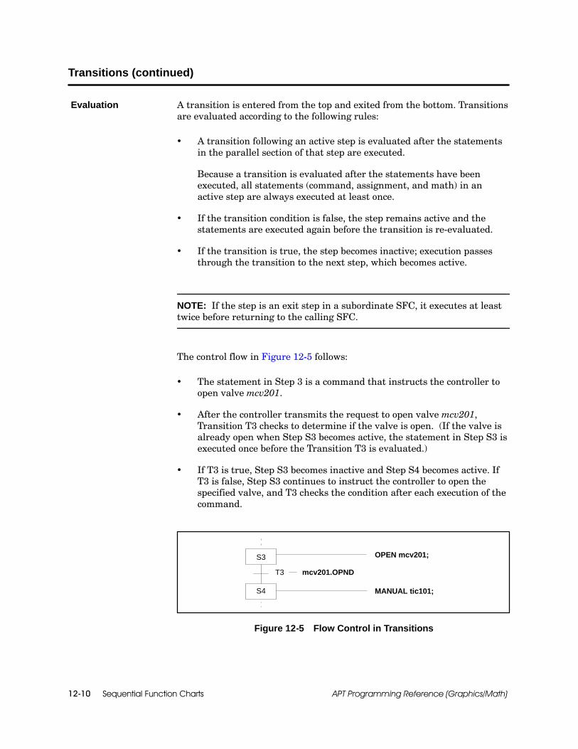
Sequential Function Charts12-10 APT Programming Reference (Graphics/Math)
Transitions (continued)
A transition is entered from the top and exited from the bottom. Transitionsare evaluated according to the following rules:
A transition following an active step is evaluated after the statementsin the parallel section of that step are executed.
Because a transition is evaluated after the statements have beenexecuted, all statements (command, assignment, and math) in anactive step are always executed at least once.
If the transition condition is false, the step remains active and thestatements are executed again before the transition is re-evaluated.
If the transition is true, the step becomes inactive; execution passesthrough the transition to the next step, which becomes active.
NOTE: If the step is an exit step in a subordinate SFC, it executes at leasttwice before returning to the calling SFC.
The control flow in Figure 12-5 follows:
The statement in Step 3 is a command that instructs the controller toopen valve mcv201.
After the controller transmits the request to open valve mcv201,Transition T3 checks to determine if the valve is open. (If the valve isalready open when Step S3 becomes active, the statement in Step S3 isexecuted once before the Transition T3 is evaluated.)
If T3 is true, Step S3 becomes inactive and Step S4 becomes active. IfT3 is false, Step S3 continues to instruct the controller to open thespecified valve, and T3 checks the condition after each execution of thecommand.
T3
S4
S3 OPEN mcv201;
MANUAL tic101;
mcv201.OPND
Figure 12-5 Flow Control in Transitions
Evaluation

Sequential Function Charts 12-11APT Programming Reference (Graphics/Math)
! CAUTIONBecause transitions are evaluated after execution of the parallel section of astep, a transition to the following step can become true before the math sectionis complete.
If a step performs operations on the data created by a previous step beforecalculations for the previous step have been completed, erroneous results canoccur. Erroneous results can cause loss of data and/or damage to equipment.
To prevent this potential error, create an APT flag to indicate when the mathsection is complete. Set the flag in the last line of the math section and use it inthe transitions that follow.
As illustrated in Figure 12-6, one method of avoiding these difficulties is toinclude an integer variable in each math section to “signal” when executionof the math block is completed. If you test that variable as part of thecondition of a transition, you can ensure that the math section is completedat least once.
MATHBEGINreal1 := real2 *ABS( real3);SCALE(in1,out1,B,0.0,1000.0);math_done := true;
math_done := false;
trueT2
math_doneT3
S4
S3
S2
Figure 12-6 Testing for Completed Execution of a Step
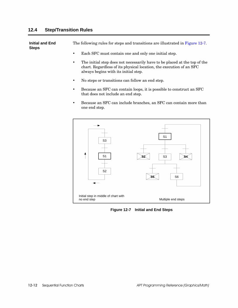
Sequential Function Charts12-12 APT Programming Reference (Graphics/Math)
12.4 Step/Transition Rules
The following rules for steps and transitions are illustrated in Figure 12-7.
Each SFC must contain one and only one initial step.
The initial step does not necessarily have to be placed at the top of thechart. Regardless of its physical location, the execution of an SFCalways begins with its initial step.
No steps or transitions can follow an end step.
Because an SFC can contain loops, it is possible to construct an SFCthat does not include an end step.
Because an SFC can include branches, an SFC can contain more thanone end step.
S2
Initial step in middle of chart withno end step Multiple end steps
S1
S3
S3
S1
S6
S2 S4
S5
Figure 12-7 Initial and End Steps
Initial and EndSteps
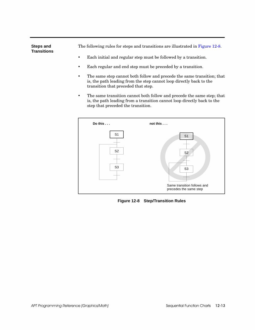
Sequential Function Charts 12-13APT Programming Reference (Graphics/Math)
The following rules for steps and transitions are illustrated in Figure 12-8.
Each initial and regular step must be followed by a transition.
Each regular and end step must be preceded by a transition.
The same step cannot both follow and precede the same transition; thatis, the path leading from the step cannot loop directly back to thetransition that preceded that step.
The same transition cannot both follow and precede the same step; thatis, the path leading from a transition cannot loop directly back to thestep that preceded the transition.
Do this . . . not this . . .
Same transition follows andprecedes the same step
S3
S2
S1
S3
S2
S1
Figure 12-8 Step/Transition Rules
Steps andTransitions

Sequential Function Charts12-14 APT Programming Reference (Graphics/Math)
12.5 Lines, Arrows, and Graphic Connections
All symbols must be connected properly to ensure that the flow of control iscontinuous. When you use the drawing icons in the SFC editor (especiallythe macros), you can accidentally leave unconnected areas between thevarious structures that you create. Use the line-draw icon to connect theunconnected symbols.
The illustration on the left side of Figure 12-9 depicts an unconnectedstructure that might result if you use the parallel macro after you use thestep-transition macro. The SFC on the right side of Figure 12-9 shows howthe structure appears after you correct it with the line-draw icon.
Extraneous lines are normally ignored if they terminate on cell boundaries;however, an extraneous line that terminates in the interior of a cell causesan error when you compile the program.
Missing linesegment
Missing linecorrectedwith Line-drawicon
S5
S3
S4 S6 S5
S3
S4 S6
Figure 12-9 Using Line-draw Icon
NOTE: Lines in an SFC cannot cross each other. See page 12-16 for amethod to avoid this problem.
Lines

Sequential Function Charts 12-15APT Programming Reference (Graphics/Math)
In some SFCs, determining the direction of control flow just by looking atthe chart may be difficult. As illustrated in Figure 12-10, you can use thearrow icon to draw arrows beside lines in an SFC to clarify the direction ofcontrol flow.
You cannot use arrows to change the direction of flow, only to document thedirection of flow in the program. Arrows are checked for accuracy when youcompile the program, and all arrows must point in the correct direction. Forexample, all of the arrows in the SFC on the right side of Figure 12-10 pointin incorrect directions and are errors that prevent the program fromcompiling.
Do this . . . not this . . .
S2 S3
S1
S2 S3
S1
Figure 12-10 Using Arrows to Document Program Flow
Arrows

Sequential Function Charts12-16 APT Programming Reference (Graphics/Math)
Lines, Arrows, and Graphic Connections (continued)
SFCs that include many lines sometimes become cluttered and difficult tointerpret, especially when they involve looping structures.
The graphic connection icon allows you to transfer control to a specified stepwithout drawing a connecting line. This makes it possible to avoidintersecting lines in an SFC. For example, the graphic connection inFigure 12-11 transfers control to Step S7 without crossing any other lines.
Functionally, a graphic connection takes the place of a line that connects atransition to a step. It must follow a transition, and it must contain thelabel of the step to which control is to be transferred. A graphic connectioncan transfer control only within an SFC, not between SFCs.
S6
Do this . . . not this . . .
S3
S1
S2
S7
S8
S5S4
S7 S6
S3
S1
S2
S8
S5S4
S7
Figure 12-11 Graphic Connections
GraphicConnections

Sequential Function Charts 12-17APT Programming Reference (Graphics/Math)
12.6 Parallel Branches
Parallel branching allows you to designate steps that execute at the sametime as other steps. A parallel branch begins with a single transition,always contains a top crossbar, and can end with a bottom crossbar.
The top crossbar follows a single transition and leads to two or moresteps.
A bottom crossbar follows two or more steps and leads to a singletransition.
The left side of Figure 12-12 shows the top crossbar leading to two parallelsteps. When Transition T2 becomes true, Steps S3 and S4 both becomeactive; each step remains active until its corresponding transition becomestrue.
The right side of Figure 12-12 shows two parallel steps leading to a bottomcrossbar that returns to a single transition. Both Steps S3 and S4 (afterthey become active) remain active until Transition T3 becomes true, atwhich time End Step S5 becomes active.
If a step that immediately precedes the bottom crossbar of a parallel branchcontains a call to a subordinate SFC, the transition that follows the crossbaris not evaluated until the end step of the subordinate SFC is active. Seepage 12-28 for information about subordinate SFCs.
S4
S2
S3
S1
T1
T2
T3 T4
S4
S2
S3
S1
S5
T1
T2
T3...
.
.
.
Figure 12-12 Simple Parallel Structures
Parallel Branching

Sequential Function Charts12-18 APT Programming Reference (Graphics/Math)
Parallel Branches (continued)
The control flow in Figure 12-13 follows:
Step S1 is active.
When Transition T1 becomes true, Step S1 becomes inactive; and stepsS2, S3, S4, and S5 become active.
Steps S2 and S3 remain active until Transition T3 becomes true. StepsS2 and S3 then become inactive, and Step S7 becomes active.
Step S4 remains active until Transition T2 becomes true.Step 4 then becomes inactive and End Step S6 becomes active.
Steps S5 and S7 remain active until Transition T4 becomes true. StepsS5 and S7 then become inactive and End Step S8 becomes active.
Transition T4 is not evaluated until both Steps S5 and S7 becomeactive. The transition that follows the bottom crossbar of a parallelbranch is not evaluated until each step that immediately precedes thecrossbar is active.
S3
S7
S2
S1
S8
T1
T3
T5
S4 S5
T2
T4
Figure 12-13 A More Complex Parallel Structure
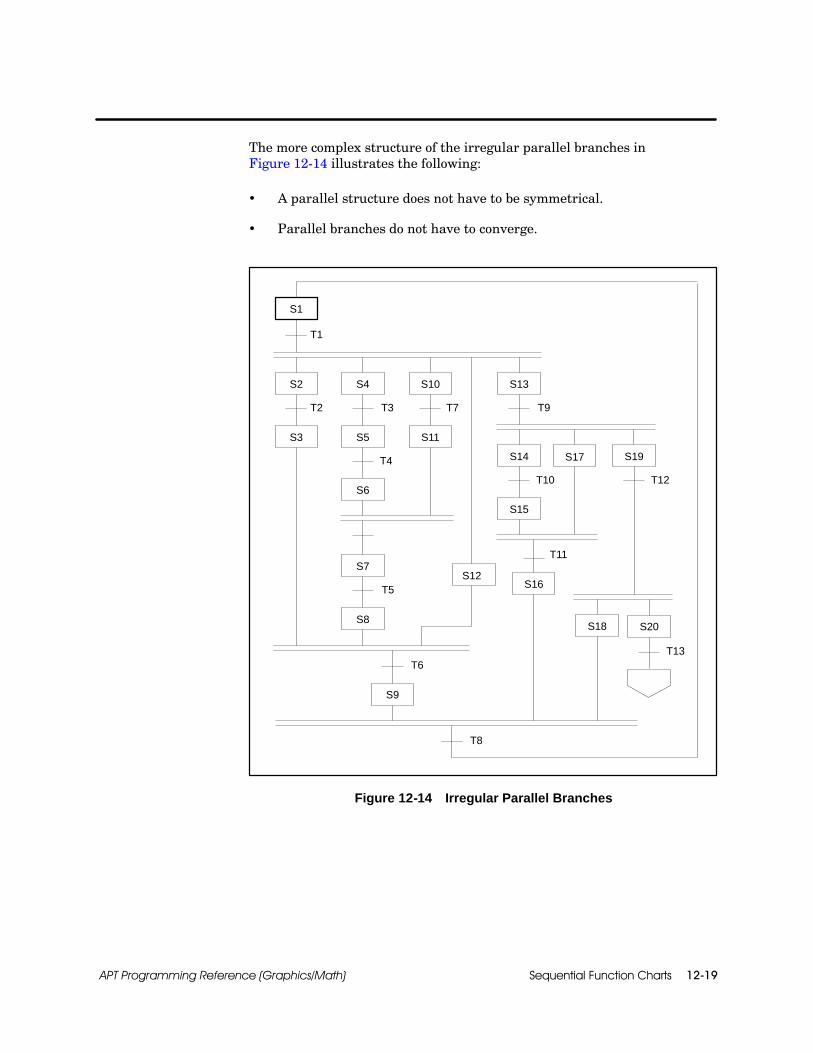
Sequential Function Charts 12-19APT Programming Reference (Graphics/Math)
The more complex structure of the irregular parallel branches inFigure 12-14 illustrates the following:
A parallel structure does not have to be symmetrical.
Parallel branches do not have to converge.
S4
S5
S1
T1
T3
T13
S6
T4
S2
S3
T2
S7
S8
T5
S10
S11
T7
S12
S9
T6
S13
T9
S14
S15
T10
S17 S19
T12
S16
T11
S20S18
T8
Figure 12-14 Irregular Parallel Branches

Sequential Function Charts12-20 APT Programming Reference (Graphics/Math)
Parallel Branches (continued)
Although the SFC Language allows you a great deal of flexibility, there area few rules that you must observe when you implement a parallel branch:
The top crossbar of a parallel branch must immediately follow a singletransition.
The top crossbar of a parallel branch can have only one entrance path,which must enter from above the crossbar.
The top crossbar of a parallel branch must have at least two exit paths,which must exit downward from the crossbar.
Each path exiting the top crossbar of a parallel branch must begin witha single step or a graphic connection.
The bottom crossbar of a parallel branch must have at least twoentrance paths, which must enter from above the crossbar.
Each path entering the bottom crossbar of a parallel branch must endwith a single step.
The bottom crossbar of a parallel branch can have only one exit path,which must exit downward from the crossbar.
The bottom crossbar of a parallel branch must be followed immediatelyby a single transition.
These rules are illustrated in Figure 12-15.
! WARNINGAPT allows the use of parallel end steps (that is, end steps in a parallel branchstructure). When any end step is encountered in a sub-SFC, control returns tothe parent SFC. If any other steps in the parallel branch are currently activewhen an end step is reached, they remain active.
Having multiple active SFC steps could cause unpredictable operation of thecontroller, which can result in death or serious injury to personnel, and/ordamage to equipment.
Avoid the use of parallel end steps in any but the Main SFC.
Parallel BranchingRules

Sequential Function Charts 12-21APT Programming Reference (Graphics/Math)
Top crossbar of a parallel branchpreceded by a convergence, notby a transition
Bottom crossbar of a parallelbranch preceded by only one step
Multiple entrances to a parallelbranch
Multiple exits from a parallel branch
Do this . . . not this . . . nor this . . .
Do this . . . not this . . . nor this . . .
Figure 12-15 Parallel Branching Rules

Sequential Function Charts12-22 APT Programming Reference (Graphics/Math)
12.7 Selection Branches
Selection branching allows you to “divert” SFC execution to one of severalpaths depending on the value of transition conditions. The paths may ormay not subsequently converge.
A selection branch begins with a single step, contains a divergence line, andcan end with a convergence line.
The divergence line follows a single step and leads to two or moretransitions.
The convergence line follows two or more transitions and leads to asingle step.
The left side of Figure 12-16 shows a divergence line leading to twotransitions. Step S2 (after it becomes active) remains active until either T2or T3 becomes true. SFC execution then proceeds to the step following thattransition. If more than one transition from a divergence line becomes truesimultaneously, SFC execution continues through the path of the leftmosttrue transition.
The right side of Figure 12-16 shows a convergence line that leads to EndStep S5 when either Transition T4 or T5 becomes true.
Divergence line
Convergenceline
S4
S2
S3
S1
S5 S6
T1
T4 T5
S4
S2
S3
S1
S5
T1
T4 T5
T2 T3 T2 T3
Figure 12-16 A Simple Selection Branch
SelectionBranching

Sequential Function Charts 12-23APT Programming Reference (Graphics/Math)
The control flow in Figure 12-17 follows:
After Step S2 becomes active, it remains active until one of thefollowing occurs.
Step S3 becomes active if Transition T2 becomes true.
Step S4 becomes active if Transition T3 becomes true before T2.
End Step S5 becomes active if Transition T4 becomes true before T2 orT3 becomes true.
When Transition T2, T3, or T4 becomes true, Step S2 becomes inactive.
Step S6 becomes active when one of the following occurs.
Transition T5 becomes true while Step S3 is active (Step S3 becomesinactive), or
Transition T6 becomes true while Step S4 is active (Step S4 becomesinactive).
Divergence line
Convergence line
S4
S2
S3
S1
S6
T1
T5 T6
T2 T3
S5
T4
Figure 12-17 A More Complex Selection Branch

Sequential Function Charts12-24 APT Programming Reference (Graphics/Math)
Selection Branches (continued)
Figure 12-18 shows an SFC with two convergences and loops. Figure 12-19shows an SFC with both selection branches and parallel branches. Try toavoid drawing very complex or irregular SFCs connections.
S3
S1
S4 S6
S7
S5
S2
Divergence line
Convergence line
Convergence line
T1 T3
T2 T4
T5 T8
T9T6
T7
T10
Figure 12-18 Two Convergences
S2
S1
S4
T1
T4
T2
S3
T3
S5
T5
T6
S8
T8
T9
S11
T10
T11
S10
S7
T7
S6
T12
S9
S12
Figure 12-19 Selection and Parallel Branches

Sequential Function Charts 12-25APT Programming Reference (Graphics/Math)
The rules that govern the implementation of a selection branch can bedivided into rules of divergence and rules of convergence.
The rules that you must observe when you implement the divergence of aselection branch follow:
A divergence is represented by a horizontal line.
A divergence must immediately follow a single step.
A divergence can have only one entrance path, which must enter fromabove the divergence line.
A divergence must have at least two exit paths, each of which mustbegin at a different point on the divergence line.
Each path exiting a divergence must begin with a single transition.
A path must exit from each endpoint of a divergence line.
A path exiting from an endpoint of a divergence line may exit upwardor downward; a path exiting between the endpoints of a divergence linemust exit downward.
A divergence does not require a subsequent convergence. (Selectionbranches do not have to converge.)
These rules are illustrated in Figure 12-20.
Multiple entrances to a selectionbranch
Do this . . . not this . . .
Figure 12-20 Divergence of a Selection Branch
SelectionBranching Rules

Sequential Function Charts12-26 APT Programming Reference (Graphics/Math)
Selection Branches (continued)
The rules that you must observe when you implement the convergence ofselection branches follow:
A convergence is represented by a horizontal line.
A convergence must have at least two entrance paths, each of whichmust end at a different point on the convergence line.
Each path entering a convergence must end with a single transition.
A path must enter each endpoint of a convergence line.
A path entering an endpoint of a convergence line may enter fromabove or below; a path entering between the endpoints of a convergenceline must enter from above.
A convergence can have only one exit path, which must exit downwardfrom the convergence line.
A convergence must be followed immediately by a single step or graphicconnection.
A convergence does not require a prior divergence. (You can use aconvergence to merge separate paths into one common path.)
These rules are illustrated in Figure 12-21.

Sequential Function Charts 12-27APT Programming Reference (Graphics/Math)
Convergence is neither precededby transitions nor followed by a step
Do this . . . not this . . .
Path does not enter at both ends of convergenceline, and path exits from selection branch, notbetween converging paths
Do this . . . not this . . .
Figure 12-21 Selection Branches

Sequential Function Charts12-28 APT Programming Reference (Graphics/Math)
12.8 Main and Subordinate SFCs
The main SFC starts the execution of program logic for a unit. Before youcompile a unit, you must use the Promote option to designate one (and onlyone) SFC as the main SFC for that unit.
APT automatically promotes the first SFC that you enter. If you enteradditional SFCs and determine that one of these should be the main SFC,promote that SFC using the Promote option.
When a unit is enabled (unit_name.ENABL is set equal to true), the mainSFC for that unit begins to execute (its initial step becomes active). Themain SFC is the only one in that unit that begins to execute automaticallywhen the unit is enabled.
If the unit is disabled (unit_name.ENABL = false), all currently active stepsin the SFC become inactive.
If the unit_name.ABORT variable is set to true, all SFC steps are forcedinactive. SFC execution does not resume when unit_name.ABORT returns tofalse.
To restart the SFC in the initial step of the main SFC, you must set theunit_name.ENABL bit to false and then to true.
The one exception to this is the case of a safe-state SFC that wastriggered before unit_name.ABORT was set to true. In this situation thesafe-state SFC does start up when unit_name.ABORT goes to false. (SeeChapter 13 for information on safe-state SFCs.)
Main SFC

Sequential Function Charts 12-29APT Programming Reference (Graphics/Math)
When you design a process control system, you often begin by dividing theprocess into a series of broadly defined basic steps; then you develop thedetails of the control sequences that comprise each of these basic steps. InAPT, you can implement this kind of control strategy through the use ofsubordinate SFCs.
A subordinate SFC is one that is “called” from another SFC. The callingSFC and the subordinate SFC must both reside in the same unit; that is,one SFC cannot call a subordinate SFC in a different unit.
You can “nest” subordinate SFCs; that is, one subordinate SFC can callanother subordinate SFC. There is no limit to the number of levels to whichyou can nest subordinate SFCs.
A subordinate SFC can be called from only one step in only one SFC. Inother words, two different SFCs cannot call the same subordinate SFC, norcan the same subordinate SFC be called from two different steps within anSFC.
To call a subordinate SFC, use:
SFC sfc_name;
The sfc_name must be the name of a subordinate SFC residing in thesame unit as the calling SFC.
A subordinate “normal” (non-safe-state) SFC can be called only from anormal SFC; a subordinate safe-state SFC can be called only from asafe-state SFC.
A subordinate SFC can be called from only one step in only one SFC.
You can use the SFC command only in initial steps and regular steps,not in end steps.
The SFC statement must be the only statement in the step. That is, astep that contains an SFC statement cannot contain any otherstatements except comments.
Subordinate SFCs

Sequential Function Charts12-30 APT Programming Reference (Graphics/Math)
Main and Subordinate SFCs (continued)
When you call an SFC, the following events occur:
The initial step of the subordinate SFC becomes active, and the callingstep in the calling SFC remains active.
The subordinate SFC executes until it reaches an end step.
The end step of the subordinate SFC and the calling step of the callingSFC remain active until the transition following the calling stepbecomes true.
When that transition becomes true, the end step of the subordinateSFC and the calling step of the calling SFC simultaneously becomeinactive; the step following the transition becomes active.
You can think of a subordinate SFC as the “expansion” of a step in thecalling SFC. For example, Figure 12-22 shows a step of an SFC that calls athree-step subordinate SFC.
Calling SFC
Subordinate SFC: cool
T1
S1
S3
T2
SFC cool;
S2
T7
T8
S8
Figure 12-22 An “Expanded” Calling Step

Sequential Function Charts 12-31APT Programming Reference (Graphics/Math)
Figure 12-23 illustrates the sequence of events that occurs when an SFCnamed r01_cntl calls a subordinate SFC named cool. The control flowfollows:
Step S8 of SFC, r01_cntl, calls the subordinate SFC cool. The executionof the calling SFC, r01_cntl, pauses at Step S8.
The subordinate SFC cool, begins to execute from its initial step, S1,and continues to execute through its end step, S4.
Step S4 remains active until Transition T8 in the calling SFC, r01_cntl,becomes true.
The execution of the calling SFC, r01_cntl, resumes at Step S9.
Subordinate SFC: cool
Calling SFC: (r01_cntl)
SFC cool;{calls subordinate SFC}
T8
S8
temp <65;{true if reactor cooled}
T1
S1
S4
T2
S2
{Initial step}
{End step}
S9
S3
T3
Figure 12-23 Subordinate SFC Execution

Safe-State SFCs 13-1APT Programming Reference (Graphics/Math)
Chapter 13
Safe-State SFCs
13.1 Overview 13-2. . . . . . . . . . . . . . . . . . . . . . . . . . . . . . . . . . . . . . . . . . . . . . . . . . . . . . . . . . . . . . . . . . . . . .Types 13-2. . . . . . . . . . . . . . . . . . . . . . . . . . . . . . . . . . . . . . . . . . . . . . . . . . . . . . . . . . . . . . . . . . . . . . . . . .Safe-State Priority 13-2. . . . . . . . . . . . . . . . . . . . . . . . . . . . . . . . . . . . . . . . . . . . . . . . . . . . . . . . . . . . . . .Safe-State SFC Operation 13-3. . . . . . . . . . . . . . . . . . . . . . . . . . . . . . . . . . . . . . . . . . . . . . . . . . . . . . . .
13.2 Safe-State Commands 13-4. . . . . . . . . . . . . . . . . . . . . . . . . . . . . . . . . . . . . . . . . . . . . . . . . . . . . . . . . .Overview 13-4. . . . . . . . . . . . . . . . . . . . . . . . . . . . . . . . . . . . . . . . . . . . . . . . . . . . . . . . . . . . . . . . . . . . . . .SSENTRY Command 13-7. . . . . . . . . . . . . . . . . . . . . . . . . . . . . . . . . . . . . . . . . . . . . . . . . . . . . . . . . . . .SSRETURN Command 13-8. . . . . . . . . . . . . . . . . . . . . . . . . . . . . . . . . . . . . . . . . . . . . . . . . . . . . . . . . .SSDEFINE Command 13-10. . . . . . . . . . . . . . . . . . . . . . . . . . . . . . . . . . . . . . . . . . . . . . . . . . . . . . . . . . .SSTRIGGER Command 13-12. . . . . . . . . . . . . . . . . . . . . . . . . . . . . . . . . . . . . . . . . . . . . . . . . . . . . . . . . .SSARM Command 13-14. . . . . . . . . . . . . . . . . . . . . . . . . . . . . . . . . . . . . . . . . . . . . . . . . . . . . . . . . . . . . .SSDISARM Command 13-15. . . . . . . . . . . . . . . . . . . . . . . . . . . . . . . . . . . . . . . . . . . . . . . . . . . . . . . . . . .SSABORT Command 13-16. . . . . . . . . . . . . . . . . . . . . . . . . . . . . . . . . . . . . . . . . . . . . . . . . . . . . . . . . . . .
13.3 Safe-State SFC Examples 13-17. . . . . . . . . . . . . . . . . . . . . . . . . . . . . . . . . . . . . . . . . . . . . . . . . . . . . . .Emergency Procedures 13-17. . . . . . . . . . . . . . . . . . . . . . . . . . . . . . . . . . . . . . . . . . . . . . . . . . . . . . . . . .Multiple Safe-State SFCs 13-19. . . . . . . . . . . . . . . . . . . . . . . . . . . . . . . . . . . . . . . . . . . . . . . . . . . . . . . . .

Safe-State SFCs13-2 APT Programming Reference (Graphics/Math)
13.1 Overview
A safe-state SFC is a special SFC that is designed to interrupt the executionof other SFCs. A safe-state SFC can execute an emergency procedure, or itcan perform special processing out of the normal flow of control.
There are three types of safe-state SFCs:
A level safe-state SFC is designed to interrupt the processing of amain or subordinate SFC. A level safe-state SFC can also interruptanother safe-state SFC with a lower priority.
A local safe-state SFC is designed to interrupt the processing of asingle SFC and any of its subordinate SFCs.
A subordinate safe-state SFC is called by another safe-state SFC(main or subordinate) in the same manner that a “normal”(non-safe-state) subordinate SFC is called by a normal SFC. Asubordinate safe-state SFC must be defined in the same manner as thecalling safe-state SFC.
Each main and subordinate level safe-state SFC must be assigned one offive priority levels, numbered 1 through 5, or a local priority. Level 1safe-state SFCs have the highest priority and override all other safe-stateSFCs. Local safe-state SFCs have the lowest priority.
A safe-state SFC with any priority can interrupt the processing ofnormal SFCs. A safe-state SFC can also interrupt the processing ofanother safe-state SFC that has a lower priority.
A safe-state SFC cannot interrupt the processing of another safe-stateSFC that has a higher or equal priority. When a safe-state SFCinterrupts the processing of another safe-state SFC, execution of theinterrupted safe-state SFC is terminated.
A safe-state SFC can call a subordinate safe-state SFC only if bothSFCs have the same priority. A safe-state SFC cannot call a normalSFC, and a normal SFC cannot call a safe-state SFC.
Only one local safe-state of any given SFC can be active at one time.However, multiple local safe-state SFCs can be active if they belong todifferent SFCs. It is possible for two local SFCs in the same subordinatepath to become active at the same time if the lowest subordinate SFCbecomes active first.
Types
Safe-State Priority

Safe-State SFCs 13-3APT Programming Reference (Graphics/Math)
When a level safe-state begins executing, all active steps in all other SFCsin the unit become inactive. When a local safe-state SFC begins executing,the associated normal SFC and its subordinate SFCs become inactive.
To set up a safe-state SFC, you need to identify the following:
Digital outputs, boolean variables, or APT flags that identify, or trigger,the events that require an interruption.
Sections of the program that can and cannot be interrupted. Sectionsthat can be interrupted are “armed.” Sections that cannot beinterrupted are “disarmed.”
Options for execution at the end of the safe-state SFC determine ifexecution continues or if the program stops when the safe-state SFC iscompleted.
! WARNINGDo not use the safe-state SFC as a replacement for a hardwired mechanicalemergency stop function.
Doing so could cause unpredictable operations that could result in death orserious injury to personnel, and/or damage to equipment.
Any safety-critical operations must always be wired independently of any solidstate computer-controlled operation. It is acceptable to use the safe-state SFCfor supplemental protective purposes if, and only if, hard-wired backup is alsoused in the event of any computer malfunction.
Safe-State SFCOperation
Safe-State SFCs13-4 APT Programming Reference (Graphics/Math)
13.2 Safe-State Commands
Seven APT commands are related to safe-state SFCs. Four of the commandscan be used only in a safe-state SFC, as is explained below.
The initial step of a safe-state SFC must contain the following twocommands:
The SSDEFINE command sets the priority (Level 1--5 or local) of thesafe-state SFC.
The SSTRIGGER command specifies the condition that triggers theaction of the safe-state SFC. The SSTRIGGER command is used only ina main safe-state SFC.
Each end step of the main SFC in level safe-state SFC network mustcontain one of the following commands:
The SSABORT command stops all SFCs.
The SSRETURN command specifies a step in a non-safe-state SFC torestart the normal processing when the safe-state SFC is completed.
Each end step of the main SFC in a local safe-state SFC network mustcontain only the SSRETURN command, and it must return to the SFCnamed in the SSDEFINE statement. The SSABORT command cannot beused in a local safe-state SFC.
Overview
Safe-State SFCs 13-5APT Programming Reference (Graphics/Math)
The other three commands are generally used outside of the safe-state SFC:
The SSARM command indicates that you want to begin monitoring thetrigger condition so that you can interrupt the process if necessary.
The SSDISARM command indicates that you want to stop monitoringthe trigger condition so that the process will no longer be subject to aninterruption.
The SSENTRY command specifies a step where you want to restart theprocess when the safe-state SFC is completed. The SSENTRYcommand is used only in a non-safe-state SFC.

Safe-State SFCs13-6 APT Programming Reference (Graphics/Math)
Safe-State Commands (continued)
Table 13-1 summarizes the restrictions concerning the safe-state commands.
Table 13-1 Safe-State Command Restrictions
Command Restrictions
SSABORT Use only in the end step of a main-level safe-state SFC; mustbe the only statement in the step.
SSARM (no restrictions)
SSDEFINE Use only in the initial step of a safe-state SFC; must be thefirst statement in the step.
SSDISARM (no restrictions)
SSENTRYUse only in a “normal” (non-safe-state) SFC; must be thefirst statement in the step or immediately following anotherSSENTRY; maximum of 10 per step.
SSRETURNUse only in the end step of a main safe-state SFC. A mainsafe-state SFC can have more than one SSRETURN butthese must be the only statements in the step.
SSTRIGGERUse only in the initial step of a main safe-state SFC; mustimmediately follow an SSDEFINE or another SSTRIGGERstatement.
Table 13-2 summarizes the steps in safe-state SFCs that have requirementsconcerning the step commands that they must contain.
Table 13-2 Safe-State SFC Step Requirements
Safe-State SFC Step Requirements
Main/Subordinate Initial Must begin with an SSDEFINEstatement.
Main InitialSSDEFINE statement must befollowed by at least one SSTRIGGERstatement.
Main EndMust include an SSABORT orSSRETURN statement; cannot includeany other type of statement.

SSENTRY
Safe-State SFCs 13-7APT Programming Reference (Graphics/Math)
The SSENTRY command defines a label that you use to indicate where theprogram returns when a safe-state issues the appropriate SSRETURNcommand.
For the SSENTRY command, use the format:
SSENTRY label;
Use the SSENTRY command only in a “normal” (non-safe-state) SFC.
The label can consist of any combination of letters, digits, andunderscores (maximum 12 characters). At least one character must bea letter. An SSENTRY label cannot be used more than once in a unit.
The SSENTRY command identifies the step in the normal SFC thatyou want to use to restart the processing after a safe-state hascompleted execution.
The SSENTRY command does not need a corresponding SSRETURNbut can be referenced by more than one SSRETURN command.
The SFC containing the step identified by the SSENTRY label mustreside in the same unit as the SFC containing the SSRETURNstatement that uses that label.
You can include as many as 10 SSENTRY statements in one step. TheSSENTRY statements must precede any other statements in the step.
The step must consist of RLL statements only.
NOTE: If an SSENTRY command is in a subordinate SFC and a safe-statereturns to that step, that step becomes active as well as the step that callsthe subordinate SFC. If this is a nested subordinate SFC, all calling stepsbecome active up to the main SFC calling step.
SSENTRYCommand

SSRETURN
Safe-State SFCs13-8 APT Programming Reference (Graphics/Math)
Safe-State Commands (continued)
The SSRETURN command transfers program execution to the stepidentified by the corresponding SSENTRY label.
For the SSRETURN command, use the format:
SSRETURN label;
You can use the SSRETURN only in the end step of a main safe-stateSFC.
The label can consist of any combination of letters, digits, andunderscores (maximum 12 characters). At least one character must bea letter.
The label must be defined by an SSENTRY statement in a “normal”(non-safe-state) SFC. An SSRETURN command terminates theexecution of a safe-state SFC.
When an SSRETURN statement executes, the step containing thatstatement is deactivated; and the step that contains the SSENTRYcommand with the same label becomes active.
The SFC containing the step identified by the SSENTRY label mustreside in the same unit as the SFC containing the SSRETURNstatement that uses that label.
The SSRETURN command of a local safe-state SFC must reference theSFC with which the local safe-state SFC is associated. The SSDEFINEcommand defines the SFC to which the local safe-state SFC is local.
You can include more than one SSRETURN statement in a step of amain safe-state SFC, but these can be the only types of statements inthe step.
NOTE: After the SSRETURN command transfers control back to thenon-safe-state SFC step that is identified by the SSENTRY command, thestatements in that step execute at least one time before another safe-stateinterruption can occur.
SSRETURNCommand

SSRETURN
Safe-State SFCs 13-9APT Programming Reference (Graphics/Math)
! WARNINGAPT allows you to specify any step as a return point for a safe state. Do notprogram a safe-state condition to return to a single step within a parallelstructure.
If your return point is a single step within a parallel structure, this step is theonly one that is active when you return, and your program is unable to advancepast the parallel structure. The consequence is unpredictable operations thatcould result in death or serious injury to personnel, and/or damage toequipment.
Figure 13-1 illustrates the type of safe-state return condition that you mustavoid.
S2
S1
S7
S3
S5
S6 Safe-state returns to S6
S4
Figure 13-1 Avoid Safe-State Return to Parallel SFC Steps

SSDEFINE
Safe-State SFCs13-10 APT Programming Reference (Graphics/Math)
Safe-State Commands (continued)
The SSDEFINE command defines an SFC as a safe-state SFC and specifiesthe priority of a safe-state SFC.
For the SSDEFINE command, use the format:
SSDEFINE LEVEL level;
SSDEFINE LEVEL level RETENTIVE;
SSDEFINE LOCAL TO sfc_name;
SSDEFINE LOCAL TO sfc_name RETENTIVE;
Use the SSDEFINE command only in the initial step of a safe-stateSFC.
The initial step of every safe-state SFC must contain one and only oneSSDEFINE statement, which must be the first statement in that step.
The LEVEL must be an integer from 1 to 5. Level 1 has the highestpriority; Level 5 has the lowest.
The SFC name is the normal SFC with which the local safe-state SFCis associated.
The priority determines what occurs when a safe-state SFC is triggeredduring the execution of another safe-state SFC.
One safe-state SFC can interrupt the execution of another safe-stateSFC only if the priority of the triggered safe-state SFC is higher thanthe priority of the currently executing safe-state SFC.
If the priority of the triggered safe-state SFC is lower than or equal tothe priority of the currently executing safe-state SFC, the execution ofthe currently executing SFC continues uninterrupted.
Only one local safe-state of any given SFC can be active at one time.However, multiple local safe-state SFCs can be active if they belong todifferent SFCs. It is possible for two local safe-state SFCs in the samesubordinate path to become active at the same time if the lowestsubordinate SFC becomes active first.
SSDEFINECommand

SSDEFINE
Safe-State SFCs 13-11APT Programming Reference (Graphics/Math)
A subordinate safe-state SFC must have the same priority level or thesame normal SFC name (local safe-state SFCs) as the SFC that calls it.
The RETENTIVE option specifies that the safe-state SFC remainsarmed if it is armed when a power failure occurs. If you do not includethe RETENTIVE option, a power failure effectively disarms a safe-stateSFC.
If you define a safe-state SFC with the RETENTIVE option, you do nothave to enable the unit to restart the process.
For Series 505 controllers, the step must consist of RLL statementsonly; this restriction does not apply to S5 controllers, into which onlySTL is loaded.

SSTRIGGER
Safe-State SFCs13-12 APT Programming Reference (Graphics/Math)
Safe-State Commands (continued)
The SSTRIGGER command specifies a condition that triggers the executionof a main safe-state SFC.
For the SSTRIGGER command, use the format:
SSTRIGGER identifier;
Use the SSTRIGGER command only in the initial step of a mainsafe-state SFC.
The identifier is the name of a digital I/O point or a boolean or APT flagvariable that triggers the execution of the safe-state SFC when itbecomes true.
When a safe-state SFC is armed and its trigger condition becomes true,it interrupts the execution of the currently executing SFC. A safe-stateSFC can interrupt a “normal” (non-safe-state) SFC or a safe-state SFCwith a lower priority.
A triggered safe-state SFC does not interrupt the processing of asafe-state SFC with a higher or equal priority.
If the trigger condition becomes true when the safe-state SFC isdisarmed, the condition is ignored.
The initial step of every main safe-state SFC must contain at least oneSSTRIGGER, which must appear immediately following theSSDEFINE.
SSTRIGGERCommand

SSTRIGGER
Safe-State SFCs 13-13APT Programming Reference (Graphics/Math)
You can use any number of SSTRIGGER statements in the initial stepof a main safe-state SFC, but all statements must immediately followthe SSDEFINE statement and precede any other types of statement.
To trigger a safe-state SFC after recovery from a power failure, specifythe power failure detection bit as the trigger condition(SSTRIGGER program_name.PWRFL;). Program execution begins withthe initial step of that safe-state SFC, assuming that the SFC wasarmed at the time of the power failure, and that the SFC was definedas retentive.
The SFC cannot be a local safe-state SFC. A local safe-state SFCcannot become active until its associated SFC is active. The associatedSFC requires several scans by the controller before becoming active;but the .PWRFL extension remains true for only one scan after returnfrom a power failure.
A retentive safe-state SFC with a .PWRFL extension as a trigger mustbe a Level 1 safe-state SFC and must be the only safe-state SFC atLevel 1. If another retentive safe-state SFC at the same or higher levelis active when the power fails, the safe-state SFC with the .PWRFLextension as a trigger does not execute.

SSARM
Safe-State SFCs13-14 APT Programming Reference (Graphics/Math)
Safe-State Commands (continued)
The SSARM command “arms” a safe-state SFC and, thus, makes it possiblefor the safe-state SFC to interrupt the processing if the trigger becomestrue.
For the SSARM command, use the format:
SSARM sfc_name;
The sfc_name must be the name of a main safe-state SFC residing inthe same unit as the currently executing SFC.
A safe-state SFC can interrupt the processing of another SFC only ifyou have armed the safe-state SFC by using the SSARM command.
When you use the SSARM command to arm a safe-state SFC, theprogram starts to monitor the conditions that are specified in theSSTRIGGER statement.
A safe-state SFC interrupts the currently executing SFC and beginsexecution only when all of the following conditions are true:
The safe-state SFC is armed. (The program constantly checks triggerconditions but ignores them until the safe-state is armed.)
The currently executing SFC is either a “normal” (non-safe-state) SFC,or a safe-state SFC with a priority that is lower than the priority of thetriggered safe-state SFC.
A trigger condition becomes true.
The SSARM remains in effect until an SSDISARM command cancels it.If the safe-state SFC is not defined as RETENTIVE, it is also disarmedby a controller power failure.
SSARM Command

SSDISARM
Safe-State SFCs 13-15APT Programming Reference (Graphics/Math)
The SSDISARM command “disarms” a safe-state SFC and, thus, does notallow a safe-state SFC to interrupt SFC processing.
For the SSDISARM command, use the format:
SSDISARM sfc_name;
The sfc_name must be the name of a main safe-state SFC residing inthe same unit as the currently executing SFC.
When you use the SSDISARM command to disarm a safe-state SFC,the safe-state SFC can no longer interrupt the processing of anotherSFC.
The SSDISARM command takes precedence over an SSARM command.
NOTE: When a unit is first enabled, all safe-state SFCs are initiallydisarmed.
SSDISARMCommand
SSABORT
Safe-State SFCs13-16 APT Programming Reference (Graphics/Math)
Safe-State Commands (continued)
The SSABORT command suspends SFC execution in the current unit.
For the SSABORT command, use the format:
SSABORT;
Use the SSABORT command only in the end step of a main-levelsafe-state SFC. You cannot use the SSABORT command with a localsafe-state SFC.
The SSABORT statement must be the only statement in the step; thatis, a step that contains an SSABORT statement cannot contain anyother statements.
When you use the SSABORT command to suspend unit execution, all SFCsin the current unit become inactive. The SFCs in the unit remain inactiveuntil you re-enable the unit.
The SSABORT command does not actually disable the unit butdeactivates the current step and leaves no steps active in any SFCs inthe unit.
The SSABORT command does not disarm any armed safe-state SFCs;therefore, it is possible for an aborted unit to become active again if thetrigger of an armed safe-state becomes true.
The SSABORT command does not affect CFBs, devices, etc. in the unit.
To re-enable the unit and reactivate the main SFC after an SSABORT hasexecuted, you must set the unit_name.ENABL bit to false and then set itback to true. You can do this with any one of the following methods.
Use the modify option in the APT Debug Utility.
Configuring the reset through an operator interface.
Use an interlock CFB with an assignment statement such asunit_name.ENABL := X1, where X1 is a Digital Input (DI) or a booleanvariable that you can use to write to the unit_name.ENABL bit to falseand then back to true.
! WARNINGIf you shut down an SFC using the SSABORT command, the safe-state SFCremains armed. It can be reactivated and cause other portions of your SFC tobegin again through the SSRETURN command.
If your safe-state SFC is still armed when your SFC reactivates, it could causeunexpected operation of your application, resulting in death or serious injury topersonnel, and/or damage to equipment.
When you use SSABORT, always disarm your safe-state SFC.
SSABORTCommand
Safe-State SFCs 13-17APT Programming Reference (Graphics/Math)
13.3 Safe-State SFC Examples
A main SFC named chrg_raw controls the charging of raw material into areactor. The pressure in the reactor increases during this procedure. If thepressure becomes too high, an emergency procedure must be performed; thesafe-state SFC named hiprs_rw controls this emergency procedure.
Figure 13-2 illustrates the sequence of events that occurs when chrg_raw isinterrupted by hiprs_rw. The control flow follows:
Step S1 of chrg_raw arms the safe-state SFC hiprs_rw. The programchecks the initial step (S1) of hiprs_rw to determine the triggercondition (pit101.INHHA).
Since the safe-state SFC is now armed, the program begins to monitorthe status of the trigger condition.
While chrg_raw is still in Step S3, the specified trigger condition ofsafe-state SFC hiprs_rw (pit101.INHHA) becomes true, indicating thatthe pressure is too high.
At this point, APT checks the priority of hiprs_rw (2) against the levelsof any other currently executing safe-state SFCs. If no Level 1 orLevel 2 safe-state SFCs are executing, hiprs_rw can interrupt theprocess.
Step S3 of chrg_raw deactivates, and the initial step of hiprs_rw isactivated; hiprs_rw executes normally, and all steps in chrg_rawremain inactive.
When hiprs_rw reaches its end step (S8), it immediately transfersexecution to the step containing the statement, SSENTRY hi_pres_lvl;and chrg_raw begins to execute normally from that step. (Step S2 ofchrg_raw is activated, and Step S8 of hipres_rw becomes inactive.)
Because hiprs_rw is still armed and is no longer executing, the statusof its trigger condition (pit101.INHHA) continues to be monitored. If thepressure becomes too high, the process is interrupted again.
When chrg_raw reaches its end step (S4), hiprs_rw is disarmed. Thestatus of its trigger condition is no longer monitored, so hiprs_rw canno longer interrupt normal processing.
EmergencyProcedures

Safe-State SFCs13-18 APT Programming Reference (Graphics/Math)
Safe-State SFC Examples (continued)
safe-state SFC: hiprs_rw
SFC: chrg_raw
SSDEFINE LEVEL 2;SSTRIGGER pit101.INHHA;
S1
T1
S1
S4
T2
S2
SSARM hiprs_rw;
S3
T3
SSENTRY hi_pres_lvl;
S8 SSRETURN hi_pres_lvl;
T1
SSDISARM hiprs_rw;{end step}
Figure 13-2 Safe-State SFC Execution
NOTE: If the safe-state hiprs_rw cannot lower the pit101.INHHA alarmduring the execution of the safe-state, hiprs_rw executes repeatedly. If yourintention is to execute a safe-state action only once, you can place thefollowing declaration in a high priority interlock block: pit101_htrig :=edge(pit101.INHHA). Then use pit101_htrig as the trigger for hiprs_rw.
Alternately, you may disarm the safe-state in the initial step of thesafe-state.

Safe-State SFCs 13-19APT Programming Reference (Graphics/Math)
Figure 13-3 illustrates how more than one safe-state SFC can interrupt amain SFC (a main SFC arms safe-state SFCs ss2, ss1, and ss4):
ss2 is a level 2 safe-state SFC that triggers when the temperature is toohigh.
ss1 is a level 1 safe-state SFC that triggers when the pressure is toohigh.
ss4 is a level 4 safe-state SFC that triggers when the pressure is toolow.
Each of the safe-state SFCs is designed to return control to the initial stepof main.
The following sequence of events is illustrated in Figure 13-3:
When the temperature becomes too high, ss2 interrupts main(Figure 13-3a).
While ss2 is executing, the pressure becomes too high. As a result, ss1(a Level 1 safe-state SFC) interrupts ss2 (a Level 2 safe-state SFC).After ss1 completes execution and returns control to main(Figure 13-3b).
Because the temperature remains too high, ss2 interrupts main as soonas the return step in the main SFC completes one execution. While ss2is executing, the pressure becomes too low. However, ss4 (a Level 4safe-state SFC), cannot interrupt ss2 (a Level 2 safe-state SFC). Whenss2 completes execution, control returns to main (Figure 13-3c).
Because the pressure remains too low, ss4 interrupts main as soon asthe return step in the main SFC completes one execution(Figure 13-3d).
Multiple Safe-StateSFCs

Safe-State SFCs13-20 APT Programming Reference (Graphics/Math)
Safe-State SFC Examples (continued)
Main SS1
SS2
SS4
Main SS2
SS1 SS4
......
...
......
...
...
...
Main SS2 SS1 SS4
......
......
Main
SS2 SS1
SS4
......
......
a
d
b
c
Figure 13-3 Safe-State Examples
Error Messages A-1APT Programming Reference (Graphics/Math)
Appendix A
Error Messages
A.1 Understanding the Compile Operation A-2. . . . . . . . . . . . . . . . . . . . . . . . . . . . . . . . . . . . . . . . . . .Overview A-2. . . . . . . . . . . . . . . . . . . . . . . . . . . . . . . . . . . . . . . . . . . . . . . . . . . . . . . . . . . . . . . . . . . . . . .Compiling with Debug A-2. . . . . . . . . . . . . . . . . . . . . . . . . . . . . . . . . . . . . . . . . . . . . . . . . . . . . . . . . . . .
A.2 Successful Compile A-3. . . . . . . . . . . . . . . . . . . . . . . . . . . . . . . . . . . . . . . . . . . . . . . . . . . . . . . . . . . .Overview A-3. . . . . . . . . . . . . . . . . . . . . . . . . . . . . . . . . . . . . . . . . . . . . . . . . . . . . . . . . . . . . . . . . . . . . . .
A.3 Compile Report Messages A-4. . . . . . . . . . . . . . . . . . . . . . . . . . . . . . . . . . . . . . . . . . . . . . . . . . . . . .Overview A-4. . . . . . . . . . . . . . . . . . . . . . . . . . . . . . . . . . . . . . . . . . . . . . . . . . . . . . . . . . . . . . . . . . . . . . .Correcting Errors A-5. . . . . . . . . . . . . . . . . . . . . . . . . . . . . . . . . . . . . . . . . . . . . . . . . . . . . . . . . . . . . . . .
A.4 Translate/Download/Debug Error Messages A-40. . . . . . . . . . . . . . . . . . . . . . . . . . . . . . . . . . . . . .Overview A-40. . . . . . . . . . . . . . . . . . . . . . . . . . . . . . . . . . . . . . . . . . . . . . . . . . . . . . . . . . . . . . . . . . . . . . .
A.5 Archive/Restore Error Messages A-43. . . . . . . . . . . . . . . . . . . . . . . . . . . . . . . . . . . . . . . . . . . . . . . .Overview A-43. . . . . . . . . . . . . . . . . . . . . . . . . . . . . . . . . . . . . . . . . . . . . . . . . . . . . . . . . . . . . . . . . . . . . . .
A.6 DOS Operating System Error Messages A-48. . . . . . . . . . . . . . . . . . . . . . . . . . . . . . . . . . . . . . . . . .

Error MessagesA-2 APT Programming Reference (Graphics/Math)
A.1 Understanding the Compile Operation
After you compile a program, APT displays one of the following messages:
Program compiled SUCCESSFULLY!
Program compiled successfully - with WARNINGS.
Program compilation cancelled prior to completion!
Compile not required. Object code is up to date.
Program compile FAILED.
The COMPILE.RPT file contains specific details about the compile.
If you compile a Debug version of your program, the messages are notaffected. The Debug Version does, however, require more controller memory.When you select the Debug version, APT creates additional code to theobject so that the Debug utility options are available.
Overview
Compiling withDebug

Error Messages A-3APT Programming Reference (Graphics/Math)
A.2 Successful Compile
When the Compile operation completes successfully, you can receive one thefollowing messages:
Program compiled SUCCESSFULLY!
Program compiled successfully - with WARNINGS.
With a successful Compile, an Object File is created; and the program isready to be downloaded to the controller. The Object File is built accordingto the specifications in the Compiler Control File.
You cannot use the APT Debug utility until you have a successful compile.
With a successful compile, the COMPILE.RPT file includes specificinformation about the compile and the amount and types of memory thatare required for the program.
When a compile completes successfully with warnings, it means thatalthough an object has been created, APT has found one or more itemswithin the program that indicate a problem.
! WARNINGAPT provides compiler warnings whenever something is detected that mightcause problems. These warnings are not compiler errors and do not stop youfrom downloading your program to the controller.
If you download your program to the controller without taking compilerwarnings into consideration, your process could be adversely affected.Unpredictable operation of the controller can result in death or serious injury topersonnel, and/or damage to equipment.
Read each compiler warning carefully and take appropriate action to correctwarning conditions before you download the compile object file into yourcontroller. A list of compiler errors and warnings, in numerical order, isprovided in Table A-1.
Overview
Error MessagesA-4 APT Programming Reference (Graphics/Math)
A.3 Compile Report Messages
The compile operation may not complete for several reasons:
Program compilation cancelled prior to completion!
This message indicates that you have aborted your compile by pressingESC . No object file has been created.
Compile not required. Object code is up to date.
This message indicates that you have not changed your APT programsince your last successful compile. If you want to recompile, selectForce Compile in the Compiler Control File.
NOTE: Be certain that you keep track of any warnings that exist in yourprogram. A recompile that results in this message creates a newCOMPILE.RPT without listing the warnings.
Program compile FAILED.
This message indicates that your program contains errors and aprogram Object File could not be created. You must correct all errorsbefore you can create an OBJECT file for downloading.
Overview

Error Messages A-5APT Programming Reference (Graphics/Math)
If your compile fails, follow these steps:
1. Review the COMPILE.RPT report for information on the errorsidentified in the compile. The error messages identify the type of errorand its location in your program. These messages are explained inTable A-1.
2. Correct all of the errors that you know how to fix, and re-compile yourprogram.
Some mistakes within your program can cause more than one error inthe COMPILE.RPT. There are errors that, when identified during thecompile, can cause a compile phase to be discontinued. Thus, if you fixan error of this type, the next compile continues further into yourprogram but identifies other errors that were not yet encountered.
NOTE: The APT Validate option can be run from various levels in thehierarchy to check individual areas of your program for syntax-relatederrors. This can save you time.
The APT Validate option cannot find all problems that relate to usingfunctions/options not supported by a specific controller model. This isidentified in a later phase of the compile operation.
Repeat Steps 1 and 2 until you complete a successful compile. If you cannotfix all your problems following these steps, compile your program with theForce Compile selected in your Compiler Control File.
If you have followed the above steps and you still receive an Internal Error,call the Siemens Energy & Automation, Inc., Technical Services Group inthe U.S.A. at (800) 333--7421. Outside the U.S.A., call 49--911--895--7000.
Correcting Errors
Error MessagesA-6 APT Programming Reference (Graphics/Math)
Compile Report Messages (continued)
Table A-1 contains a list of errors that can appear in the COMPILE.RPTfile. Many of these errors can be detected if you use the Validate optionwhile you are building your program.
The line numbers for errors that occur in SFC Steps, Transitions and MathCFBs are calculated as accurately as possible but can be off by one or twolines.
Several errors can be flagged due to a single mistake in your program. Ifmultiple errors occur within the same area of your program, fix the obviouserror, typically listed first.
General errors and graphical errors are included in the table.
When a range error occurs, the following formats are used:
x .. y means that the value must be greater than or equal to x and lessthan or equal to y.
x >. y means that the value must be greater than x and less than orequal to y.
x .< y means that the value must be greater than or equal to x and lessthan y.
x >< y means that the value must be greater than x and less than y.
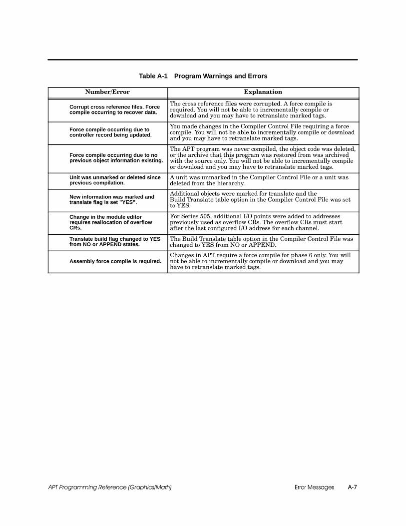
Error Messages A-7APT Programming Reference (Graphics/Math)
Table A-1 Program Warnings and Errors
Number/Error Explanation
Corrupt cross reference files. Forcecompile occurring to recover data.
The cross reference files were corrupted. A force compile isrequired. You will not be able to incrementally compile ordownload and you may have to retranslate marked tags.
Force compile occurring due tocontroller record being updated.
You made changes in the Compiler Control File requiring a forcecompile. You will not be able to incrementally compile or downloadand you may have to retranslate marked tags.
Force compile occurring due to noprevious object information existing.
The APT program was never compiled, the object code was deleted,or the archive that this program was restored from was archivedwith the source only. You will not be able to incrementally compileor download and you may have to retranslate marked tags.
Unit was unmarked or deleted sinceprevious compilation.
A unit was unmarked in the Compiler Control File or a unit wasdeleted from the hierarchy.
New information was marked andtranslate flag is set ”YES”.
Additional objects were marked for translate and theBuild Translate table option in the Compiler Control File was setto YES.
Change in the module editorrequires reallocation of overflowCRs.
For Series 505, additional I/O points were added to addressespreviously used as overflow CRs. The overflow CRs must startafter the last configured I/O address for each channel.
Translate build flag changed to YESfrom NO or APPEND states.
The Build Translate table option in the Compiler Control File waschanged to YES from NO or APPEND.
Assembly force compile is required.Changes in APT require a force compile for phase 6 only. You willnot be able to incrementally compile or download and you mayhave to retranslate marked tags.

Error MessagesA-8 APT Programming Reference (Graphics/Math)
Compile Report Messages (continued)
Table A-1 Program Warnings and Errors (continued)
Number/Error Explanation
2003 Program compiled with nounits marked.
The program has units, but they are not marked for compile. Theinformation in all units will not be compiled and will not exist inthe controller.
2007 Unit ... contains no main SFC.An SFC needs to be promoted in this unit. Each unit within yourprogram must have one and only one main (promoted) SFC, whichis used as the starting point of all sequential control for that unit.
2013 Undefined controller record. This message is caused by an error in the Compiler Control File. Afield has been left empty or contains an invalid entry.
2014 No controller version numbergiven.
This message is caused by an error in the Compiler Control File.The controller version field has been left empty or contains aninvalid entry.
2015 No TISOFT version numbergiven.
(Series 505 only) This message is caused by an error in theCompiler Control File. The TISOFT version field has been leftempty or contains an invalid entry.
2016 Cannot find APT connector inparallel port. This error does not apply to APT Release 1.9 and later.
2019 APT SYSTEM ERROR:Program file not found....
APT attempted to execute one of the compile phases, e.g., SFC,NNL, assembler, etc., and was unable to find an executableprogram. Make sure that the DOS path includes the \aptsubdirectory and that all files with .exe extensions are in thissubdirectory.
2020 APT SYSTEM ERROR: DOSerror executing... Return code...
An error occurred while executing one of the compile phases. Exitfrom APT and run the DOS CHKDSK /F command; and thenreboot. The return code is a specific DOS error number. Refer tothe DOS user manual for an explanation.
2023 Program compile interrupted:Swap file load failed ....
The compile was interrupted by a Ctrl-Break from the keyboard, oran error occurred while loading an executable swap file. Try tocompile the program again. If this fails, exit from APT and run theDOS CHKDSK /F command; and then reboot.
2024 No main global SFC. An SFC is not promoted at the global level. Promote one SFC asthe main SFC.
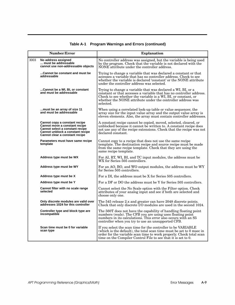
Error Messages A-9APT Programming Reference (Graphics/Math)
Table A-1 Program Warnings and Errors (continued)
Number/Error Explanation
3003 No address assigned... must be addressablecannot use non-addressable objects
No controller address was assigned, but the variable is being usedby the program. Check that the variable is not declared with theNONE attribute under the controller address.
...Cannot be constant and must beaddressable
Trying to change a variable that was declared a constant or thataccesses a variable that has no controller address. Check to seewhether the variable is declared ‘constant’ or the NONE attributeunder the controller address was selected.
...Cannot be a WI, BI, or constantand must be addressable
Trying to change a variable that was declared a WI, BI, or aconstant or that accesses a variable that has no controller address.Check to see whether the variable is a WI, BI, or constant, orwhether the NONE attribute under the controller address wasselected.
...must be an array of size 11and must be addressable
When using a correlated look-up table or value sequencer, thearray size for the input value array and the output value array iseleven elements. Also, the array must contain controller addresses.
Cannot copy a constant recipeCannot move a constant recipeCannot select a constant recipeCannot unblock a constant recipeCannot clear a constant recipe
A constant recipe cannot be copied, moved, selected, cleared, orunblocked because it cannot be written to. A constant recipe doesnot use any of the recipe extensions. Check that the recipe was notdeclared constant.
Parameters must have same recipetemplate
Cannot copy to a recipe that does not use the same recipetemplate. The destination recipe and source recipe must be madefrom the same recipe template. Check that they are using thesame recipe template.
Address type must be WX For AI, RT, WI, BI, and TC input modules, the address must beWX for Series 505 controllers.
Address type must be WY For an AO, BO, and WO output modules, the address must be WYfor Series 505 controllers.
Address type must be X For a DI, the address must be X for Series 505 controllers.
Address type must be Y For a DF or DO the address must be Y for Series 505 controllers.
Cannot filter with no scale rangeselected
Cannot select the No Scale option with the Filter option. Checkattributes of your analog input and see if both are selected andchoose only one.
Only discrete modules are valid overaddresses 1024 for this controller
The 545 release 2.x and greater can have 2048 discrete points.Check that only discrete I/O modules are used in the second 1024.
Controller type and block type areincompatible
The 560T does not have the capability of handling floating pointnumbers (reals). The CFB you are using uses floating pointnumbers in its calculations. This error also occurs with an S5controller when you try to use an unsupported CFB.
Scan time must be 0 for variablescan type
If you select the scan time for the controller to be VARIABLE(which is the default), the total scan time must be set to 0 msec inorder for the variable scan time to work properly. Check total scantime on the Compiler Control File to see that it is set to 0.
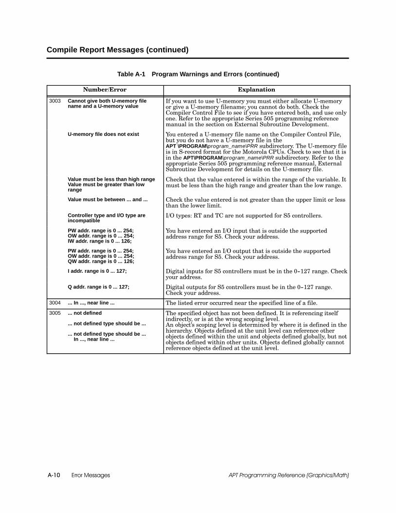
Error MessagesA-10 APT Programming Reference (Graphics/Math)
Compile Report Messages (continued)
Table A-1 Program Warnings and Errors (continued)
Number/Error Explanation
3003 Cannot give both U-memory filename and a U-memory value
If you want to use U-memory you must either allocate U-memoryor give a U-memory filename; you cannot do both. Check theCompiler Control File to see if you have entered both, and use onlyone. Refer to the appropriate Series 505 programming referencemanual in the section on External Subroutine Development.
U-memory file does not exist You entered a U-memory file name on the Compiler Control File,but you do not have a U-memory file in theAPT \PROGRAM\program_name\PRR subdirectory. The U-memory fileis in S-record format for the Motorola CPUs. Check to see that it isin the APT\PROGRAM\program_name\PRR subdirectory. Refer to theappropriate Series 505 programming reference manual, ExternalSubroutine Development for details on the U-memory file.
Value must be less than high rangeValue must be greater than lowrange
Check that the value entered is within the range of the variable. Itmust be less than the high range and greater than the low range.
Value must be between ... and ... Check the value entered is not greater than the upper limit or lessthan the lower limit.
Controller type and I/O type areincompatible
I/O types: RT and TC are not supported for S5 controllers.
PW addr. range is 0 ... 254;OW addr. range is 0 ... 254;IW addr. range is 0 ... 126;
You have entered an I/O input that is outside the supportedaddress range for S5. Check your address.
PW addr. range is 0 ... 254;OW addr. range is 0 ... 254;QW addr. range is 0 ... 126;
You have entered an I/O output that is outside the supportedaddress range for S5. Check your address.
I addr. range is 0 ... 127; Digital inputs for S5 controllers must be in the 0--127 range. Checkyour address.
Q addr. range is 0 ... 127; Digital outputs for S5 controllers must be in the 0--127 range.Check your address.
3004 ... In ..., near line ... The listed error occurred near the specified line of a file.
3005 ... not defined
... not defined type should be ...
... not defined type should be ...In ..., near line ...
The specified object has not been defined. It is referencing itselfindirectly, or is at the wrong scoping level.An object’s scoping level is determined by where it is defined in thehierarchy. Objects defined at the unit level can reference otherobjects defined within the unit and objects defined globally, but notobjects defined within other units. Objects defined globally cannotreference objects defined at the unit level.
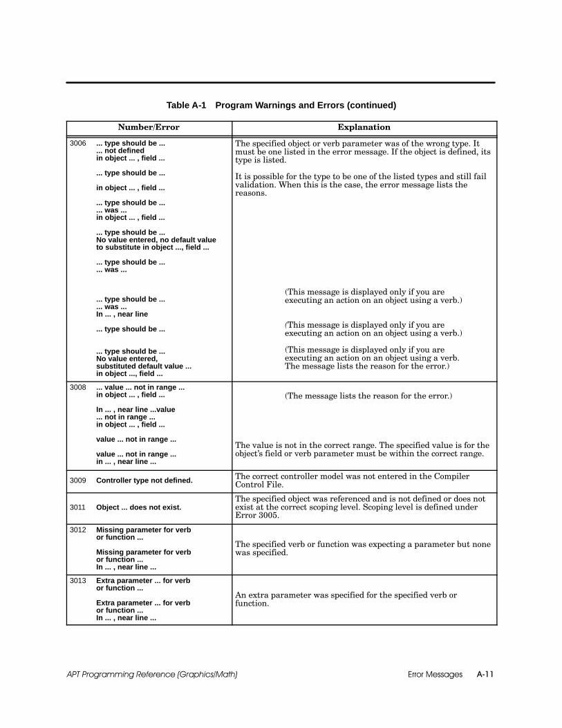
Error Messages A-11APT Programming Reference (Graphics/Math)
Table A-1 Program Warnings and Errors (continued)
Number/Error Explanation
3006 ... type should be ...... not definedin object ... , field ...
... type should be ...
in object ... , field ...
... type should be ...
... was ...in object ... , field ...
... type should be ...No value entered, no default valueto substitute in object ..., field ...
... type should be ...
... was ...
... type should be ...
... was ...In ... , near line
... type should be ...
... type should be ...No value entered,substituted default value ...in object ..., field ...
The specified object or verb parameter was of the wrong type. Itmust be one listed in the error message. If the object is defined, itstype is listed.
It is possible for the type to be one of the listed types and still failvalidation. When this is the case, the error message lists thereasons.
(This message is displayed only if you areexecuting an action on an object using a verb.)
(This message is displayed only if you areexecuting an action on an object using a verb.)
(This message is displayed only if you areexecuting an action on an object using a verb.The message lists the reason for the error.)
3008 ... value ... not in range ...in object ... , field ...
In ... , near line ...value... not in range ...in object ... , field ...
value ... not in range ...
value ... not in range ...in ... , near line ...
(The message lists the reason for the error.)
The value is not in the correct range. The specified value is for theobject’s field or verb parameter must be within the correct range.
3009 Controller type not defined. The correct controller model was not entered in the CompilerControl File.
3011 Object ... does not exist.The specified object was referenced and is not defined or does notexist at the correct scoping level. Scoping level is defined underError 3005.
3012 Missing parameter for verbor function ...
Missing parameter for verbor function ...In ... , near line ...
The specified verb or function was expecting a parameter but nonewas specified.
3013 Extra parameter ... for verbor function ...
Extra parameter ... for verbor function ...In ... , near line ...
An extra parameter was specified for the specified verb orfunction.

Error MessagesA-12 APT Programming Reference (Graphics/Math)
Compile Report Messages (continued)
Table A-1 Program Warnings and Errors (continued)
Number/Error Explanation
3014 Object missing for verb or function ... The object of the verb was not specified.
3015 Invalid verb ... for object ...
Invalid verb ... for object ...In ..., near line ...
The specified verb is not valid for the specified object.
3018 Value ... cannot be a constantboolean.
Value in specified field cannot be a constant boolean.
3019 Value ... must be literal or declaredconstant in object ... , field ...
Value in specified field must be a literal or declared constant.Check value and its scoping level. Scoping level is defined underError 3005.
3020 Declaration for ... not found.A declared variable was referenced and was not defined or was notat the correct scoping level. Scoping level is defined underError 3005.
3021 String ... truncated. An input line is too long.
3022 Cannot open package bodylibrary ...
The library that expands the control code for an object could not beopened. Therefore, the objects of the specified type will not containany control code. This may be caused by the deletion or corruptionof the library. Call (800) 333--7421 in the U.S.A., or49--911--895--7000 outside the U.S.A., for assistance.
4007 Not enough memory to load ...package
The package that defines information for an APT object could notbe loaded because there is not enough memory. Use memorymanagement techniques to get more conventional memory. Forinstance, try to load as much as you can in extended memory usingan extended memory manager. You need at least 510K in order torun APT. See the appendix called “APT Computer Memory,” in theSIMATIC APT User Manual.
4008 Cannot open input library ...
The library that defines information for an object could not beopened. Therefore, all the standard object types shipped with APTcannot be used correctly. This may be caused by the deletion orcorruption of the library. Call (800) 333--7421 in the U.S.A., or49--911--895--7000 outside the U.S.A., for assistance.

Error Messages A-13APT Programming Reference (Graphics/Math)
Table A-1 Program Warnings and Errors (continued)
Number/Error Explanation
5018 field was <empty>, type shouldbe ... in object ..., field ...
The field of the specified object is empty. It must contain one of thetypes listed in the message.
5019 ... type should be ... literal inobject ... , field ...
The field of the specified object must contain a literal of the typelisted in the message.
5020 Real addresses require ... memorylocations
For Series 505, integers require one memory location and realnumbers require two memory locations. For example, V1. refers toboth V1 and V2. For S5 controllers, integers require two flagmemory locations and real numbers require four flag memorylocations. For example, FD1 refers to FY1, FY2, FY3, and FY4. Fordata memory in DB/DXs in S5 controllers, integers require onememory location and real numbers require two memory locations.For example, DB3:D1. refers to both D1 and D2.
5021 I/O name ... has no addressassigned.
The specified I/O object was not assigned an address in the moduletable.
5022 No value entered, substituteddefault value ...
The problem usually occurs on a restored program from a previousrelease. This goes away after the first compile.
5023 No value entered, no default valueto substitute.
The problem usually occurs on a restored program from a previousrelease. The field must be initialized with a value.
5024 Math was selected but not definedin object ... , field ...
User-defined math was selected but no math statements wereentered. If this message is displayed as a warning, the compile willnot fail. If this message is displayed as an error, you must enterthe math statements before the program will compile.
5026 Constant value ... assigned torecipe element ... in recipe ... hasnot been declared.
Constant value ... assigned torecipe element ... in recipe ... is notof the correct type.
A problem was encountered assigning a constant value to thespecified recipe element. It was not declared, not the correct type,or does not exist at the correct scoping level. Scoping level isdefined under Error 3005.
5030 Address format ... is invalid.(Start with “%”, no “ . ” allowed).
The address format is incorrect. It must be preceded with a % sign,contain an address type (e.g., V, C, K, etc., for Series 505 and FW,DW, SW, etc., for S5), and be followed by the address offset. Itcannot contain any trailing characters, including a trailing period.
5031 ... is an invalid address in object ...,field ...
The address type was not valid (i.e., VMX instead of VMM), theformat was incorrect (i.e. %VMMFF00 instead of %VMM0FF00),and/or the address was not an odd VMM or VMS offset.
5032 ... requiring ... locations is out ofrange (... reserved)in object ..., field ...
All elements of an array with a user defined address must bewithin the reserved address range.
... requiring ... locations is out ofrange (... reserved)value ... not in range ...returned address crossretentive/non-retentive boundaryin object ..., field ...
The specified range in the message is the closest valid range basedon the starting address and array length. For Series 505 booleanarrays, requested array range may cross retentive/non-retentiveboundary.
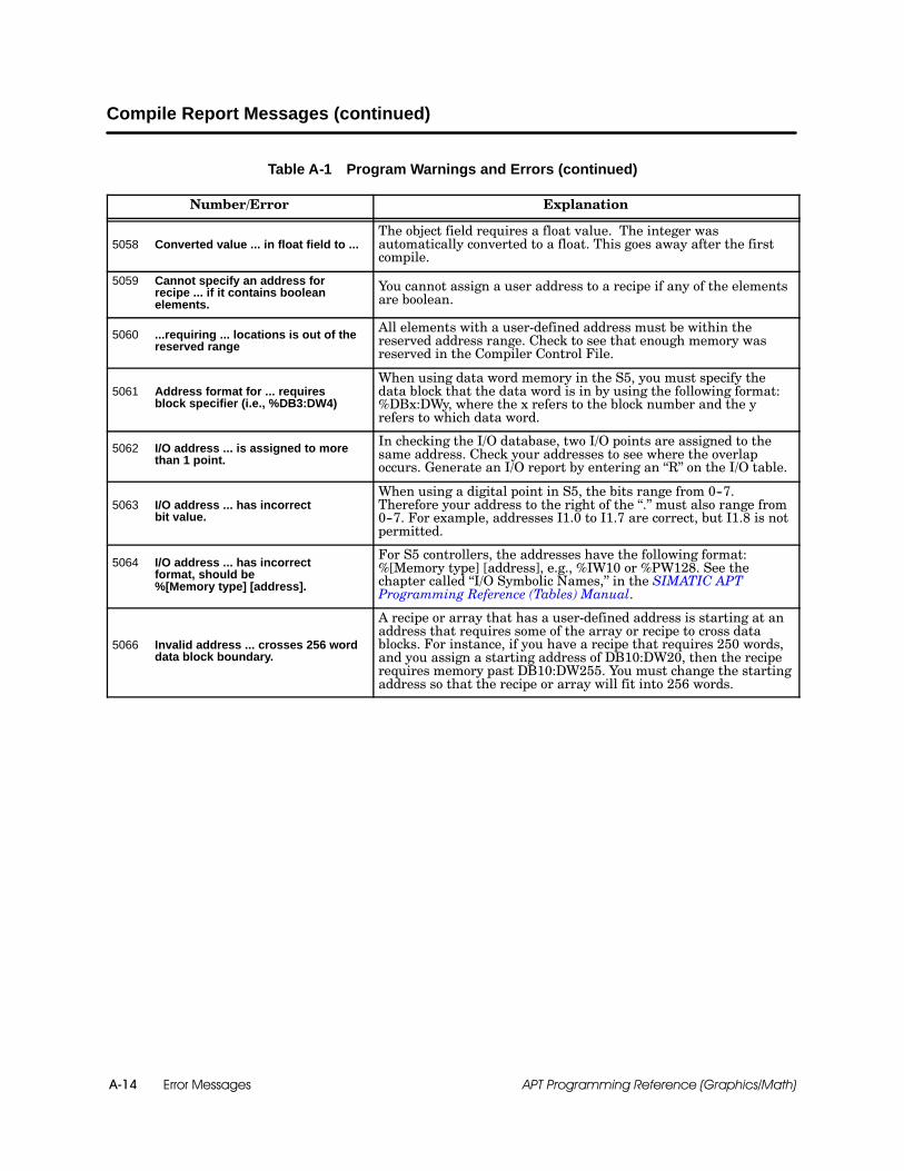
Error MessagesA-14 APT Programming Reference (Graphics/Math)
Compile Report Messages (continued)
Table A-1 Program Warnings and Errors (continued)
Number/Error Explanation
5058 Converted value ... in float field to ...The object field requires a float value. The integer wasautomatically converted to a float. This goes away after the firstcompile.
5059 Cannot specify an address forrecipe ... if it contains booleanelements.
You cannot assign a user address to a recipe if any of the elementsare boolean.
5060 ...requiring ... locations is out of thereserved range
All elements with a user-defined address must be within thereserved address range. Check to see that enough memory wasreserved in the Compiler Control File.
5061 Address format for ... requiresblock specifier (i.e., %DB3:DW4)
When using data word memory in the S5, you must specify thedata block that the data word is in by using the following format:%DBx:DWy, where the x refers to the block number and the yrefers to which data word.
5062 I/O address ... is assigned to morethan 1 point.
In checking the I/O database, two I/O points are assigned to thesame address. Check your addresses to see where the overlapoccurs. Generate an I/O report by entering an “R” on the I/O table.
5063 I/O address ... has incorrectbit value.
When using a digital point in S5, the bits range from 0--7.Therefore your address to the right of the “.” must also range from0--7. For example, addresses I1.0 to I1.7 are correct, but I1.8 is notpermitted.
5064 I/O address ... has incorrectformat, should be%[Memory type] [address].
For S5 controllers, the addresses have the following format:%[Memory type] [address], e.g., %IW10 or %PW128. See thechapter called “I/O Symbolic Names,” in the SIMATIC APTProgramming Reference (Tables) Manual.
5066 Invalid address ... crosses 256 worddata block boundary.
A recipe or array that has a user-defined address is starting at anaddress that requires some of the array or recipe to cross datablocks. For instance, if you have a recipe that requires 250 words,and you assign a starting address of DB10:DW20, then the reciperequires memory past DB10:DW255. You must change the startingaddress so that the recipe or array will fit into 256 words.

Error Messages A-15APT Programming Reference (Graphics/Math)
Table A-1 Program Warnings and Errors (continued)
Number/Error Explanation
7000 The Sub-SFC ... that is called from ...doesn’t exist.
The SFC references a Sub-SFC that does not exist. Correct thespelling or create the named SFC.
7001 SFC ... is called from more than oneSFC (... and ...). An SFC can only be referenced from one SFC.
7002 SFC ... is not called. An SFC must be a main SFC or referenced by another SFC.
7003 SFC ... and Sub-SFC ... are differentlevel safe-state SFCs. All safe-state sub-SFCs must be the same level as the calling SFC.
7004 SFC ... is attempting to call the mainSFC ... Cannot call the main SFC. The main SFC cannot be called from another SFC.
7005 SFC ... is attempting to callsafe-state SFC ... No calls allowedto safe-state SFCs.
A normal SFC cannot call a safe-state SFC.
7006 The trigger ... appears at morethan one level.
An SSTRIGGER statement appears in two safe-state SFCs withthe same priority.
7007 The trigger ... is used morethan once at the same level.
The same trigger has been used for two safe-state SFCs that aredefined at the same level. Change the trigger or the level for eitherSFC.
7009 SFC ... cannot disarm or arm ..., it isnot a SFC.
The SFC tries to disarm or arm a safe-state SFC that does notexist. Correct the spelling or create the named SFC.
7010 SFC ... cannot disarm or arm SFC ...,it is not a main safe-state SFC. An SFC can only disarm or arm a main level safe-state.
7011 Duplicate safe-state entry point ... inSFCs ... and ...
An SSENTRY point is defined more than one time. Removeduplicate SSENTRY points.
7012 Safe-state entry point ... referencedin SFC ... does not exist.
An SSRETURN statement has a label that does not exist or cannotbe found. Check for typographical errors or a label that is morethan 12 characters; verify that a valid SFC contains the properSSENTRY statement.
7013 Maximum SFCs of 64 exceeded inunit ... You can have no more than 64 SFCs in any one unit.
7014 The local SFC ... identified insafe-state ... does not exist.
A local safe-state must reference a normal SFC. Correct thespelling or create the named SFC.
7015 The ssreturn ... in SFC ... does notreturn to the local-to SFC ...
An SSRETURN statement of a local safe-state SFC must return tothe SFC to which it is local. Change the SSRETURN statement sothat it points to an entry point inside the LOCAL-TO SFC.
7016 SFC ... is not local to the same SFCas its parent ... All safe-state sub-SFCs must be the same level as the calling SFC.
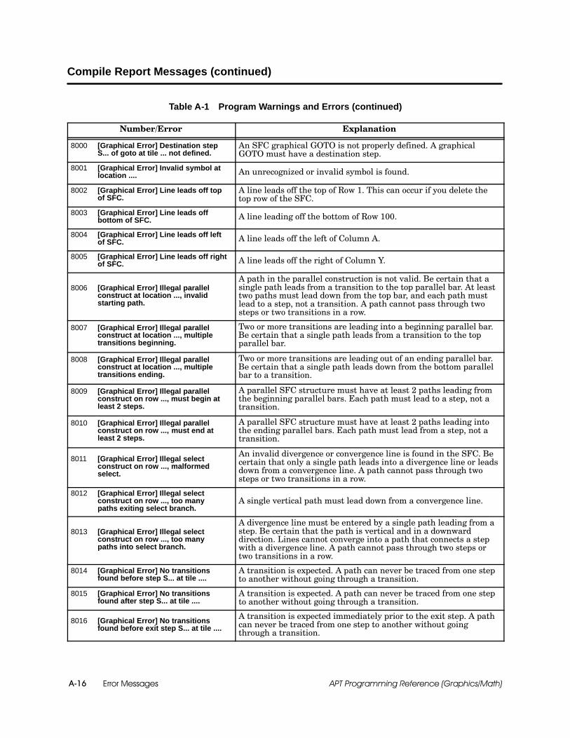
Error MessagesA-16 APT Programming Reference (Graphics/Math)
Compile Report Messages (continued)
Table A-1 Program Warnings and Errors (continued)
Number/Error Explanation
8000 [Graphical Error] Destination stepS... of goto at tile ... not defined.
An SFC graphical GOTO is not properly defined. A graphicalGOTO must have a destination step.
8001 [Graphical Error] Invalid symbol atlocation .... An unrecognized or invalid symbol is found.
8002 [Graphical Error] Line leads off topof SFC.
A line leads off the top of Row 1. This can occur if you delete thetop row of the SFC.
8003 [Graphical Error] Line leads offbottom of SFC. A line leading off the bottom of Row 100.
8004 [Graphical Error] Line leads off leftof SFC. A line leads off the left of Column A.
8005 [Graphical Error] Line leads off rightof SFC. A line leads off the right of Column Y.
8006 [Graphical Error] Illegal parallelconstruct at location ..., invalidstarting path.
A path in the parallel construction is not valid. Be certain that asingle path leads from a transition to the top parallel bar. At leasttwo paths must lead down from the top bar, and each path mustlead to a step, not a transition. A path cannot pass through twosteps or two transitions in a row.
8007 [Graphical Error] Illegal parallelconstruct at location ..., multipletransitions beginning.
Two or more transitions are leading into a beginning parallel bar.Be certain that a single path leads from a transition to the topparallel bar.
8008 [Graphical Error] Illegal parallelconstruct at location ..., multipletransitions ending.
Two or more transitions are leading out of an ending parallel bar.Be certain that a single path leads down from the bottom parallelbar to a transition.
8009 [Graphical Error] Illegal parallelconstruct on row ..., must begin atleast 2 steps.
A parallel SFC structure must have at least 2 paths leading fromthe beginning parallel bars. Each path must lead to a step, not atransition.
8010 [Graphical Error] Illegal parallelconstruct on row ..., must end atleast 2 steps.
A parallel SFC structure must have at least 2 paths leading intothe ending parallel bars. Each path must lead from a step, not atransition.
8011 [Graphical Error] Illegal selectconstruct on row ..., malformedselect.
An invalid divergence or convergence line is found in the SFC. Becertain that only a single path leads into a divergence line or leadsdown from a convergence line. A path cannot pass through twosteps or two transitions in a row.
8012 [Graphical Error] Illegal selectconstruct on row ..., too manypaths exiting select branch.
A single vertical path must lead down from a convergence line.
8013 [Graphical Error] Illegal selectconstruct on row ..., too manypaths into select branch.
A divergence line must be entered by a single path leading from astep. Be certain that the path is vertical and in a downwarddirection. Lines cannot converge into a path that connects a stepwith a divergence line. A path cannot pass through two steps ortwo transitions in a row.
8014 [Graphical Error] No transitionsfound before step S... at tile ....
A transition is expected. A path can never be traced from one stepto another without going through a transition.
8015 [Graphical Error] No transitionsfound after step S... at tile ....
A transition is expected. A path can never be traced from one stepto another without going through a transition.
8016 [Graphical Error] No transitionsfound before exit step S... at tile ....
A transition is expected immediately prior to the exit step. A pathcan never be traced from one step to another without goingthrough a transition.
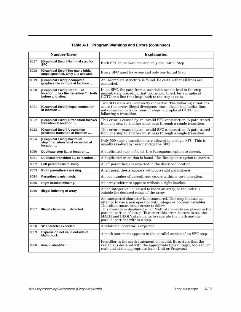
Error Messages A-17APT Programming Reference (Graphics/Math)
Table A-1 Program Warnings and Errors (continued)
Number/Error Explanation
8017 [Graphical Error] No initial step forSFC. Each SFC must have one and only one Initial Step.
8018 [Graphical Error] Too many initialsteps specified. Only 1 is allowed. Every SFC must have one and only one Initial Step.
8019 [Graphical Error] Incompletegraphics tile in input at location ....
An incomplete structure is found. Be certain that all lines areconnected.
8020 [Graphical Error] Step S... atlocation ... has the transition T... bothbefore and after.
In an SFC, the path from a transition cannot lead to the stepimmediately preceding that transition. Check for a graphicalGOTO or a line that loops back to the step it exits.
8021 [Graphical Error] Illegal connectionat location ....
Two SFC steps are incorrectly connected. The following situationscause this error: illegal divergence lines, illegal loop backs, linesnot connected to transitions or steps, a graphical GOTO notfollowing a transition.
8022 [Graphical Error] A transition followstransition at location ....
This error is caused by an invalid SFC construction. A path tracedfrom one step to another must pass through a single transition.
8023 [Graphical Error] A transitionprecedes transition at location ....
This error is caused by an invalid SFC construction. A path tracedfrom one step to another must pass through a single transition.
8024 [Graphical Error] Maximumstep / transition label exceeded atlocation ...
Only 500 steps / transitions are allowed in a single SFC. This isusually resolved by resequencing the SFC.
8050 Duplicate step S... at location ... A duplicated step is found. Use Resequence option to correct.
8051 Duplicate transition T... at location ... A duplicated transition is found. Use Resequence option to correct.
8052 Left parenthesis missing. A left parenthesis is expected in the described location.
8053 Right parenthesis missing. A left parenthesis appears without a right parenthesis.
8054 Parenthesis mismatch. An odd number of parentheses occurs within a verb operation.
8055 Right bracket missing. An array reference appears without a right bracket.
8056 Illegal indexing of array. A non-integer value is used to index an array, or the index isoutside the declared range of the array.
8057 Illegal character ... detected.
An unexpected character is encountered. This may indicate anattempt to use a real operator with integer or boolean variables.This often causes other errors to follow.This message is displayed when Math statements are placed in theparallel portion of a step. To correct this error, be sure to use theMATH and BEGIN statements to separate the math and theparallel portions within a step.
8058 ‘=’ character expected. A relational operator is expected.
8059 Expression not valid outside ofMath block A math statement appears in the parallel section of an SFC step.
8060 Invalid identifier ....Identifier in the math statement is invalid. Be certain that thevariable is declared with the appropriate type (integer, boolean, orreal) and at the appropriate level (Unit or Program.)

Error MessagesA-18 APT Programming Reference (Graphics/Math)
Compile Report Messages (continued)
Table A-1 Program Warnings and Errors (continued)
Number/Error Explanation
8061 Invalid direct controller identifier ....
A direct controller address has been found that is invalid. Becertain that the syntax of the identifier and the controller size arecorrect. An example of an invalid address is %WW97. (WW is not avalid controller address type.)
8062 Comment not closed.The closing delimiter for a comment is not found. Commentsshould be enclosed with one of the following delimiters: {...} or(*...*).
8063 Invalid based integer .... Base other than 2 (binary), 10 (decimal), or 16 (hexadecimal)appears in the program.
8064 Safe-state level expected. An SSDEFINE statement appears without a valid safe-statepriority. Valid priority levels are 1, 2, 3, 4, and 5.
8065 Semicolon expected before ... End of a statement is expected. APT statements must end withsemicolons.
8066 Integer value expected.An integer is expected. Array references and assignments withintegers and some functions and procedure require integervariables.
8067 Identifier expected. The statement requires an identifier. Check for an incompleteexpression or statement.
8068 Invalid hexadecimal integer .... An invalid hexadecimal integer is found. Check references in theDeclaration Table.
8069 Invalid binary integer .... An invalid binary integer is found. Check references in theDeclaration Table.
8070 Invalid decimal integer .... An invalid decimal integer has been encountered. Check referencesin the Declaration Table.
8071 Based integers not allowed inexpression.
A decimal integer is required. The expression does not supportbases of 2 or 16. If this occurs the binary or hexadecimal valuemust be replaced with its decimal equivalent. An SSDEFINEstatement requires a literal decimal value to define the safe-statepriority.
8072 Invalid safe state level. A safe-state priority other than 1,2,3,4, or 5 is found.
8073 Undeclared identifier ...
Identifier is not declared in I/O Symbolic Table, Declaration Table,Recipe Templates, or in list of object extensions. This can alsooccur because of a syntax error in an APT command or an illegalmath statement in the parallel section of an SFC step.
For the 560 and 560T controllers, this error can occur when ananalog input module is used. If the variable in the error is of typeAI and you are using one of these controllers, be sure to use the.RAW extension of the AI point. This is because APT cannot scale orfilter analog alarms with these controllers.
8074 Invalid symbol type in expression. The symbolic name type of an identifier does not match therequired type (real, integer, boolean, APT flag, and array).
8075 Array index not valid.
A non-integer value is used to index an array, or the index isoutside the declared range of the array. Some instructions use onlythe array name (without an index). This error also occurs whenyou index a non-array variable.
8076 Array index required. An array variable appears without an index.

Error Messages A-19APT Programming Reference (Graphics/Math)
Table A-1 Program Warnings and Errors (continued)
Number/Error Explanation
8077 Invalid real number .... An invalid real number or real number expression is found.
8078 No SSABORT or SSRETURN allowedin
step.
An SSABORT or SSRETURN statement appears in anon-safe-state SFC end step.
8079 Identifier expected. The statement requires an identifier. Check for an incompleteexpression or statement.
8080 Only SSABORT or SSRETURNallowed in step.
End step of a safe-state SFC contains something other than anSSABORT or SSRETURN statement.
8081 An SFC statement must be the onlystatement in a step.
The call to a subordinate SFC, can be the only statement in thecalling step.
8082 Too many SSENTRY statementsdeclared for step.
The step contains more than the allowed number of safe-stateentry point statements. There can be up to 10 SSENTRYstatements in a step.
8083 ‘:=’ operator expected. Assignment operator (:=) is expected in assignment statement.
8084 Right side of assignment statementmissing.
Assignment statement not complete. Check for missinginformation on the right side of a assignment (:=) operator.
8085 Unexpected input ‘...’. Element is not expected in the specified location. This message canoccur if math expressions are placed in a transition.
8086 Flag variable required for command. Command (ON, LATCH, CLEAR) requires an APT flag variable.Check Declaration Table or I/O Symbolic Table.
8087 SFC file ... either empty or corrupted.Compiler cannot compile the specified SFC. Be certain that theSFC is valid. If the problem persists it may indicate a database oroperating system problem.
8089 Illegal mixing of types inassignment or boolean statement.
A value or expression is assigned to a variable of a different type.For example, INT1 := true where INT1 is an integer. This erroralso occurs when a step or transition statement should evaluate toa boolean but does not.This message is also displayed when an assignment is made suchas Recipe1:= Recipe2; and Recipe1 and Recipe 2 have differenttemplates.
8090 Boolean expression expected.A boolean expression is expected. Transitions must contain asingle boolean expression. A blank transition can also cause thiserror.
8091 Arrays are not of the same size. Certain APT statements require that the included arrays have thesame declared number of elements.
8092 Identifier ... is read-only. Variable is a read-only (a declared constant or an input such as aWI).
8093 SSENTRY statement must be firststatement in step.
An SSENTRY statement appears some place other than the firstline of an SFC step. Multiple SSENTRY statements are allowed aslong as they appear before any other executable statements.
8095 Real value . . . is not in range[--9.223372E18 . . --2.710501E--20, 0.0,5.421011E--20 . . +9.223372E18]
A real number was entered outside of its usable range.
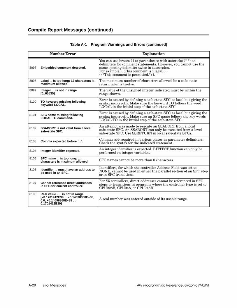
Error MessagesA-20 APT Programming Reference (Graphics/Math)
Compile Report Messages (continued)
Table A-1 Program Warnings and Errors (continued)
Number/Error Explanation
8097 Embedded comment detected.
You can use braces { } or parentheses with asterisks (* *) asdelimiters for comment statements. However, you cannot use thesame opening delimiter twice in succession.For example, { {This comment is illegal} }.{ (*This comment is permitted.*) }.
8098 Label ... is too long: 12 characters ismaximum allowed.
The maximum number of characters allowed for a safe-statereturn label is twelve.
8099 Integer ... is not in range[0..65535].
The value of the unsigned integer indicated must be within therange shown.
8100 TO keyword missing followingkeyword LOCAL.
Error is caused by defining a safe-state SFC as local but giving thesyntax incorrectly. Make sure the keyword TO follows the wordLOCAL in the initial step of the safe-state SFC.
8101 SFC name missing followingLOCAL TO command.
Error is caused by defining a safe-state SFC as local but giving thesyntax incorrectly. Make sure an SFC name follows the key wordsLOCAL TO in the initial step of the safe-state SFC.
8102 SSABORT is not valid from a localsafe-state SFC.
An attempt was made to execute an SSABORT from a localsafe-state SFC. An SSABORT can only be executed from a levelsafe-state SFC. Use SSRETURN in local safe-state SFCs.
8103 Comma expected before ’...’. Commas are required in various places as parameter delimiters.Check the syntax for the indicated statement.
8104 Integer identifier expected. An integer identifier is expected. BITTEST function can only beperformed on integer variables.
8105 SFC name ... is too long: ...characters is maximum allowed. SFC names cannot be more than 8 characters.
8106 Identifier ... must have an address tobe used in an SFC.
Identifiers, for which the controller Address Field was set toNONE, cannot be used in either the parallel section of an SFC stepor in SFC transitions.
8107 Cannot reference direct addressesin SFC for current controller.
For S5 controllers, direct addresses cannot be referenced in SFCsteps or transitions in programs where the controller type is set toCPU928B, CPU948, or CPU948R.
8108 Real value . . . is not in range[--0.1701412E39 . . --0.14698368E--38,0.0, +0.14698368E--38 . .0.1701412E39]
A real number was entered outside of its usable range.
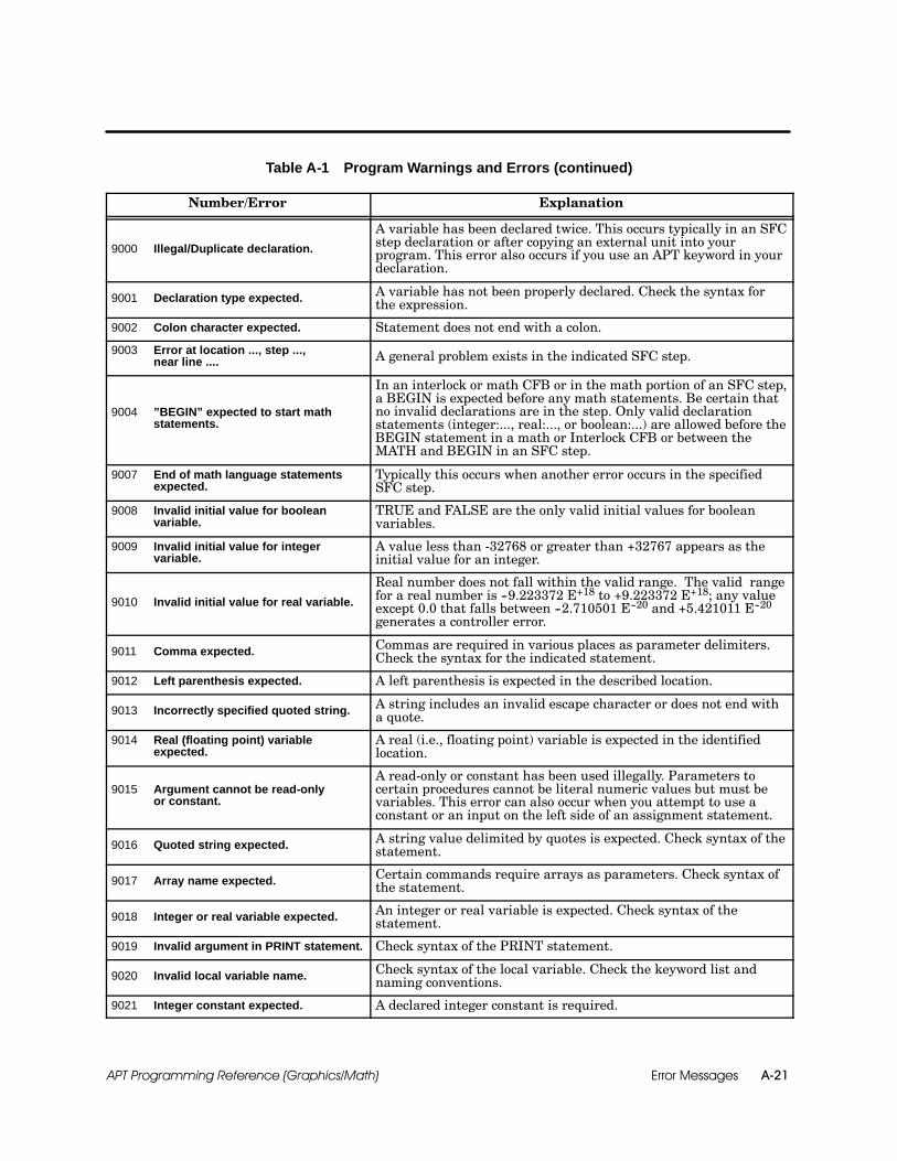
Error Messages A-21APT Programming Reference (Graphics/Math)
Table A-1 Program Warnings and Errors (continued)
Number/Error Explanation
9000 Illegal/Duplicate declaration.
A variable has been declared twice. This occurs typically in an SFCstep declaration or after copying an external unit into yourprogram. This error also occurs if you use an APT keyword in yourdeclaration.
9001 Declaration type expected. A variable has not been properly declared. Check the syntax forthe expression.
9002 Colon character expected. Statement does not end with a colon.
9003 Error at location ..., step ...,near line .... A general problem exists in the indicated SFC step.
9004 ”BEGIN” expected to start mathstatements.
In an interlock or math CFB or in the math portion of an SFC step,a BEGIN is expected before any math statements. Be certain thatno invalid declarations are in the step. Only valid declarationstatements (integer:..., real:..., or boolean:...) are allowed before theBEGIN statement in a math or Interlock CFB or between theMATH and BEGIN in an SFC step.
9007 End of math language statementsexpected.
Typically this occurs when another error occurs in the specifiedSFC step.
9008 Invalid initial value for booleanvariable.
TRUE and FALSE are the only valid initial values for booleanvariables.
9009 Invalid initial value for integervariable.
A value less than -32768 or greater than +32767 appears as theinitial value for an integer.
9010 Invalid initial value for real variable.
Real number does not fall within the valid range. The valid rangefor a real number is --9.223372 E+18 to +9.223372 E+18; any valueexcept 0.0 that falls between --2.710501 E--20 and +5.421011 E--20generates a controller error.
9011 Comma expected. Commas are required in various places as parameter delimiters.Check the syntax for the indicated statement.
9012 Left parenthesis expected. A left parenthesis is expected in the described location.
9013 Incorrectly specified quoted string. A string includes an invalid escape character or does not end witha quote.
9014 Real (floating point) variableexpected.
A real (i.e., floating point) variable is expected in the identifiedlocation.
9015 Argument cannot be read-onlyor constant.
A read-only or constant has been used illegally. Parameters tocertain procedures cannot be literal numeric values but must bevariables. This error can also occur when you attempt to use aconstant or an input on the left side of an assignment statement.
9016 Quoted string expected. A string value delimited by quotes is expected. Check syntax of thestatement.
9017 Array name expected. Certain commands require arrays as parameters. Check syntax ofthe statement.
9018 Integer or real variable expected. An integer or real variable is expected. Check syntax of thestatement.
9019 Invalid argument in PRINT statement. Check syntax of the PRINT statement.
9020 Invalid local variable name. Check syntax of the local variable. Check the keyword list andnaming conventions.
9021 Integer constant expected. A declared integer constant is required.

Error MessagesA-22 APT Programming Reference (Graphics/Math)
Compile Report Messages (continued)
Table A-1 Program Warnings and Errors (continued)
Number/Error Explanation
9022 Possible nested comment.
Use braces { } or parentheses with asterisks (* *) as delimiters forcomment statements. You cannot use an opening delimiter twice insuccession.For example, { {This comment is illegal} }.{ (*This comment is permitted.*) }.
9023 Beginning of poorly formedcomment.
Typically, this message is displayed when a comment is opened butnot closed.
9024 Illegal mixing of types nearexpression....
One or more items in the expression are of the wrong type or needto be of the same type.
9026 Bad argument for function orprocedure call.
A Math function or procedure is incorrectly programmed. Typically,a typographical error exists or an invalid variable type has beenused.
9027 Undefined/illegal function orprocedure call.
A Math function or procedure is incorrectly programmed. Typically,a typographical error exists or an invalid variable type has beenused.
9028 Array not proper size. The statement requires the array used to be of a specific size.
9029 Poorly formed loop construct. Typically, this occurs when a WHILE loop is not properly closedwith an END LOOP statement.
9030 Boolean Array name expected. An array of a certain type is expected. Check the syntax of thestatements indicated.
9031 Real (float) Array name expected. An array of a certain type is expected. Check the syntax of thestatements indicated.
9032 Integer Array name expected. An array of a certain type is expected. Check the syntax of thestatements indicated.
9033 Integer or Real (float) Arrayname expected.
An array of a certain type is expected. Check the syntax of thestatements indicated.
9034 Integer or Real (float) Addressexpected.
The type of a statement address is incorrect. Check the syntax ofthe statements indicated.
9035 Real (floating point) value expected. The type of value expected is incorrect. Check the syntax of thestatements indicated.
9036 Integer value expected. The type of value expected is incorrect. Check the syntax of thestatements indicated.
9037 Parameter type mismatch. One or more variables on the line are of the wrong type. Check thesyntax of the statements indicated.
9038 Illegal type mixing. One or more variables on the line are of the wrong type. Check thesyntax of the statements indicated.
9039 Component of a structure or recipeis not an assignable location.
An attempt was made to assign a value to a recipe element thatdoes not have an address.
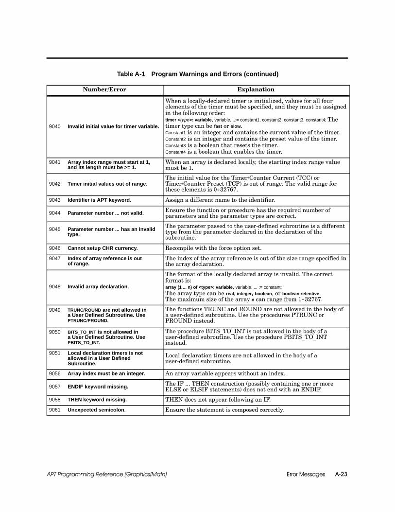
Error Messages A-23APT Programming Reference (Graphics/Math)
Table A-1 Program Warnings and Errors (continued)
Number/Error Explanation
9040 Invalid initial value for timer variable.
When a locally-declared timer is initialized, values for all fourelements of the timer must be specified, and they must be assignedin the following order:timer <type>: variable, variable,...:= constant1, constant2, constant3, constant4; Thetimer type can be fast or slow.Constant1 is an integer and contains the current value of the timer.Constant2 is an integer and contains the preset value of the timer.Constant3 is a boolean that resets the timer.Constant4 is a boolean that enables the timer.
9041 Array index range must start at 1,and its length must be >= 1.
When an array is declared locally, the starting index range valuemust be 1.
9042 Timer initial values out of range.The initial value for the Timer/Counter Current (TCC) orTimer/Counter Preset (TCP) is out of range. The valid range forthese elements is 0--32767.
9043 Identifier is APT keyword. Assign a different name to the identifier.
9044 Parameter number ... not valid. Ensure the function or procedure has the required number ofparameters and the parameter types are correct.
9045 Parameter number ... has an invalidtype.
The parameter passed to the user-defined subroutine is a differenttype from the parameter declared in the declaration of thesubroutine.
9046 Cannot setup CHR currency. Recompile with the force option set.
9047 Index of array reference is outof range.
The index of the array reference is out of the size range specified inthe array declaration.
9048 Invalid array declaration.
The format of the locally declared array is invalid. The correctformat is:array (1 ... n) of <type>: variable, variable, ... := constant;The array type can be real, integer, boolean, or boolean retentive.The maximum size of the array n can range from 1--32767.
9049 TRUNC/ROUND are not allowed ina User Defined Subroutine. UsePTRUNC/PROUND.
The functions TRUNC and ROUND are not allowed in the body ofa user-defined subroutine. Use the procedures PTRUNC orPROUND instead.
9050 BITS_TO_INT is not allowed ina User Defined Subroutine. UsePBITS_TO_INT.
The procedure BITS_TO_INT is not allowed in the body of auser-defined subroutine. Use the procedure PBITS_TO_INTinstead.
9051 Local declaration timers is notallowed in a User DefinedSubroutine.
Local declaration timers are not allowed in the body of auser-defined subroutine.
9056 Array index must be an integer. An array variable appears without an index.
9057 ENDIF keyword missing. The IF ... THEN construction (possibly containing one or moreELSE or ELSIF statements) does not end with an ENDIF.
9058 THEN keyword missing. THEN does not appear following an IF.
9061 Unexpected semicolon. Ensure the statement is composed correctly.
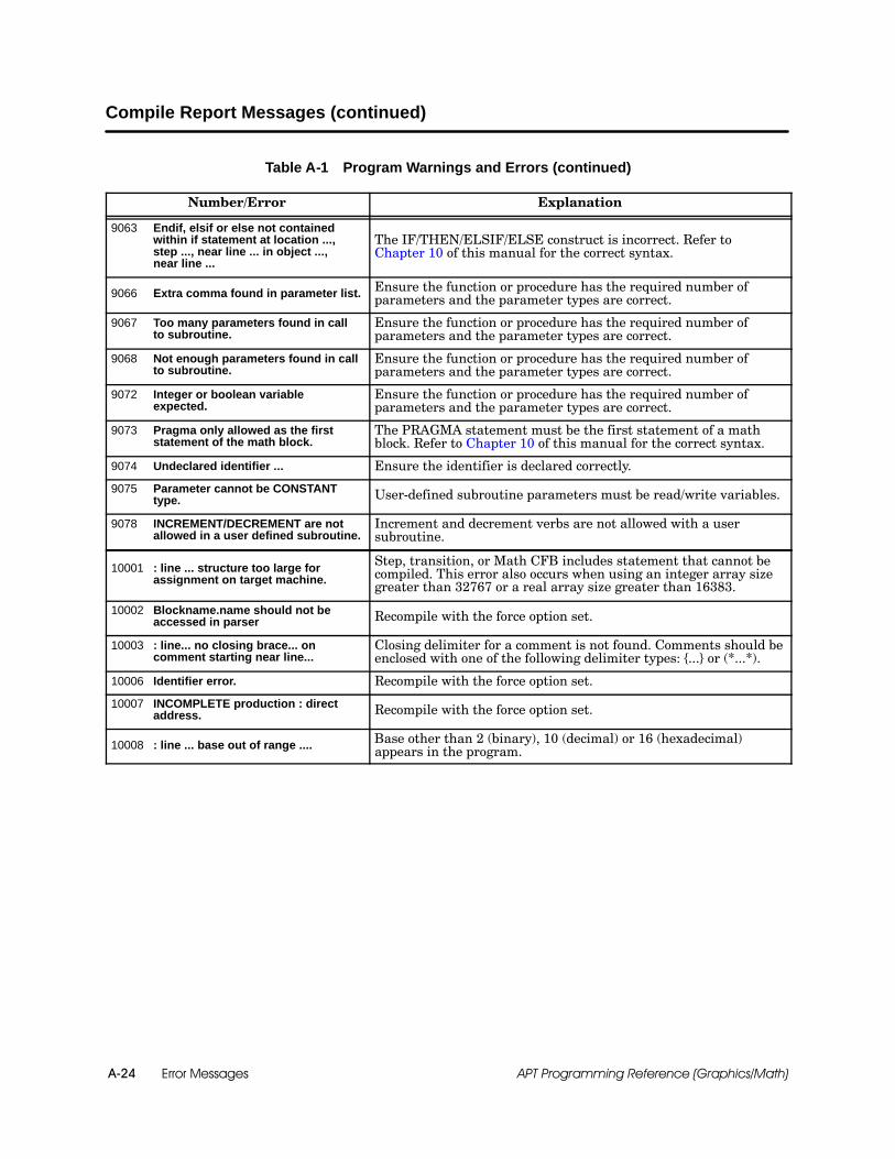
Error MessagesA-24 APT Programming Reference (Graphics/Math)
Compile Report Messages (continued)
Table A-1 Program Warnings and Errors (continued)
Number/Error Explanation
9063 Endif, elsif or else not containedwithin if statement at location ...,step ..., near line ... in object ...,near line ...
The IF/THEN/ELSIF/ELSE construct is incorrect. Refer toChapter 10 of this manual for the correct syntax.
9066 Extra comma found in parameter list. Ensure the function or procedure has the required number ofparameters and the parameter types are correct.
9067 Too many parameters found in callto subroutine.
Ensure the function or procedure has the required number ofparameters and the parameter types are correct.
9068 Not enough parameters found in callto subroutine.
Ensure the function or procedure has the required number ofparameters and the parameter types are correct.
9072 Integer or boolean variableexpected.
Ensure the function or procedure has the required number ofparameters and the parameter types are correct.
9073 Pragma only allowed as the firststatement of the math block.
The PRAGMA statement must be the first statement of a mathblock. Refer to Chapter 10 of this manual for the correct syntax.
9074 Undeclared identifier ... Ensure the identifier is declared correctly.
9075 Parameter cannot be CONSTANTtype. User-defined subroutine parameters must be read/write variables.
9078 INCREMENT/DECREMENT are notallowed in a user defined subroutine.
Increment and decrement verbs are not allowed with a usersubroutine.
10001 : line ... structure too large forassignment on target machine.
Step, transition, or Math CFB includes statement that cannot becompiled. This error also occurs when using an integer array sizegreater than 32767 or a real array size greater than 16383.
10002 Blockname.name should not beaccessed in parser Recompile with the force option set.
10003 : line... no closing brace... oncomment starting near line...
Closing delimiter for a comment is not found. Comments should beenclosed with one of the following delimiter types: {...} or (*...*).
10006 Identifier error. Recompile with the force option set.
10007 INCOMPLETE production : directaddress. Recompile with the force option set.
10008 : line ... base out of range .... Base other than 2 (binary), 10 (decimal) or 16 (hexadecimal)appears in the program.

Error Messages A-25APT Programming Reference (Graphics/Math)
Table A-1 Program Warnings and Errors (continued)
Number/Error Explanation
10010 Digit ... not valid for base. Recompile with the force option set.
10014 Invalid block/subroutine definition. Recompile with the force option set.
10015 Subroutine declaration error. Recompile with the force option set.
10016 User defined types not supported. Recompile with the force option set.
10017 Unary minus not supported. Recompile with the force option set.
10018 Reserved range for C memorylocations above ... not checked.
Phase 4 cannot check if the retentive or non-retentive C-memorylocations are reserved correctly in the Compiler Control File. Youare responsible.
10020 Duplicate declaration of block ... Recompile with the force option set.
10021 Duplicate declaration ofsubroutine ... Recompile with the force option set.
10022 Public declaration hidden by localdeclaration ... Recompile with the force option set.
10023 Multiply declared identifier ... Recompile with the force option set.
10024 Multiply declared public identifier ... Recompile with the force option set.
10025 Block ... not declared. Recompile with the force option set.
10026 Range not checked on retentive Cmemory locations.
Phase 4 cannot check if the retentive C-memory locations arereserved correctly in the Compiler Control File. You areresponsible.
10027 Emit rll compare error. Recompile with the force option set.
10028 Range not checked. Recompile with the force option set.
10030 Unit ... not declared. Recompile with the force option set.
10031 Object of assign.array notaccessible. Recompile with the force option set.
10032 Boolean xor not supported. Recompile with the force option set.
10033 Variable.variable not accessible. Recompile with the force option set.
10034 Object of assign.id not accessible. Recompile with the force option set.
10042 Function can not return complextype. Recompile with the force option set.
10043 Records not supported asparameters to subroutines. Recompile with the force option set.

Error MessagesA-26 APT Programming Reference (Graphics/Math)
Compile Report Messages (continued)
Table A-1 Program Warnings and Errors (continued)
Number/Error Explanation
10044 Initial value not supported for ...subtype. Recompile with the force option set.
10046 Symbol table interface error. Recompile with the force option set.
10047 : line ... symbol table error :symbol ... name too long
The maximum number of characters permitted is 38. This messageapplies to all symbol names. For example, this number includesthe SFC name (preceded by $), the step name, the user-declaredvariable name, and periods separating them.
10048 Cannot add table ... Recompile with the force option set.
10050 Could not open unit and globaltables. Recompile with the force option set.
10051 ... ms table not found. Recompile with the force option set.
10052 No block name. Recompile with the force option set.
10053 Must be declaration section. Recompile with the force option set.
10054 : line ... FATAL error out of memory.
The compiler has run out of memory (i.e., an operating systemlimitation). This occurs when a step, transition, or Math CFBincludes compound statement that cannot be converted into thetarget control during a compile. If you receive this error, divide theidentified statement into several smaller statements withoutchanging the intended logic.
10056 Internal symbol table error. Recompile with the force option set.
10057 ... must be a block name. Recompile with the force option set.
10058 ... does not exist. Recompile with the force option set.
10060 : line ... cannot check status of ...Variable on the indicated line has not been declared or generated,and, therefore, its status cannot be checked. Check the source orthe variable (Declaration Tables, I/O, object extensions, etc.).
10061 Variable or array extension notaccessible. Recompile with the force option set.
10062 Line ... arrays have differentdimensions
Arrays used in the statement on the indicated line must haveidentical dimensions.
10063 Line ... index out of range for array .... A non-integer value is used to index an array, or the index isoutside the declared range of the array.
10064 Array index not an integer or integerexpression. Recompile with the force option set.
10066 Array length must be positive. Recompile with the force option set.
10067 Array index must be one. Recompile with the force option set.
10068 Formal actual parameter mismatch. Recompile with the force option set.
10070 : line ... illegal array index :boolean array indexed byexpression
Boolean arrays can be indexed only by literal values such as 5,7, 9,16, etc.
10071 Complex types not supported forarrays. Recompile with the force option set.
10072 Operand type conflict. Recompile with the force option set.
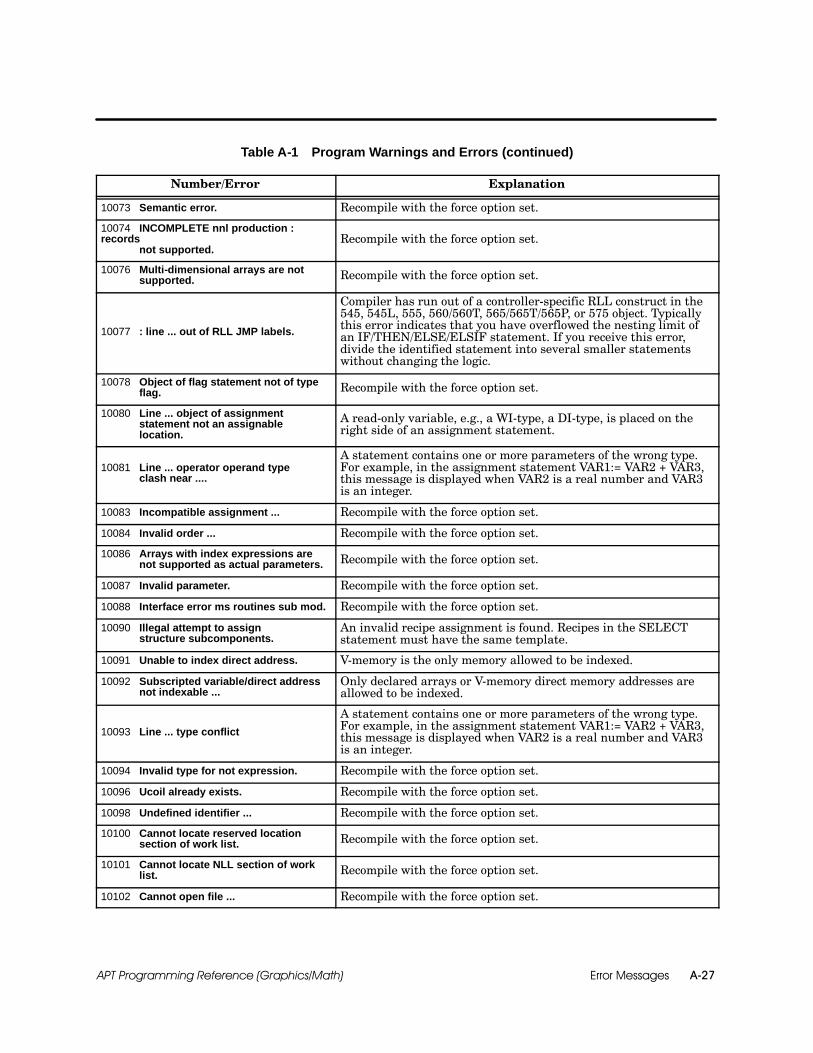
Error Messages A-27APT Programming Reference (Graphics/Math)
Table A-1 Program Warnings and Errors (continued)
Number/Error Explanation
10073 Semantic error. Recompile with the force option set.
10074 INCOMPLETE nnl production :records
not supported.Recompile with the force option set.
10076 Multi-dimensional arrays are notsupported. Recompile with the force option set.
10077 : line ... out of RLL JMP labels.
Compiler has run out of a controller-specific RLL construct in the545, 545L, 555, 560/560T, 565/565T/565P, or 575 object. Typicallythis error indicates that you have overflowed the nesting limit ofan IF/THEN/ELSE/ELSIF statement. If you receive this error,divide the identified statement into several smaller statementswithout changing the logic.
10078 Object of flag statement not of typeflag. Recompile with the force option set.
10080 Line ... object of assignmentstatement not an assignablelocation.
A read-only variable, e.g., a WI-type, a DI-type, is placed on theright side of an assignment statement.
10081 Line ... operator operand typeclash near ....
A statement contains one or more parameters of the wrong type.For example, in the assignment statement VAR1:= VAR2 + VAR3,this message is displayed when VAR2 is a real number and VAR3is an integer.
10083 Incompatible assignment ... Recompile with the force option set.
10084 Invalid order ... Recompile with the force option set.
10086 Arrays with index expressions arenot supported as actual parameters. Recompile with the force option set.
10087 Invalid parameter. Recompile with the force option set.
10088 Interface error ms routines sub mod. Recompile with the force option set.
10090 Illegal attempt to assignstructure subcomponents.
An invalid recipe assignment is found. Recipes in the SELECTstatement must have the same template.
10091 Unable to index direct address. V-memory is the only memory allowed to be indexed.
10092 Subscripted variable/direct addressnot indexable ...
Only declared arrays or V-memory direct memory addresses areallowed to be indexed.
10093 Line ... type conflict
A statement contains one or more parameters of the wrong type.For example, in the assignment statement VAR1:= VAR2 + VAR3,this message is displayed when VAR2 is a real number and VAR3is an integer.
10094 Invalid type for not expression. Recompile with the force option set.
10096 Ucoil already exists. Recompile with the force option set.
10098 Undefined identifier ... Recompile with the force option set.
10100 Cannot locate reserved locationsection of work list. Recompile with the force option set.
10101 Cannot locate NLL section of worklist. Recompile with the force option set.
10102 Cannot open file ... Recompile with the force option set.

Error MessagesA-28 APT Programming Reference (Graphics/Math)
Compile Report Messages (continued)
Table A-1 Program Warnings and Errors (continued)
Number/Error Explanation
10103 Cannot open assembly.apd file ... Recompile with the force option set.
10104 Internal error : unable to opensystem file nnl.dat. Recompile with the force option set.
10106 Cannot open file ... Recompile with the force option set.
10107 Cannot open work list. Recompile with the force option set.
10108 Path error ... Recompile with the force option set.
10110 Unexpected end of file encounteredin work list. Recompile with the force option set.
10111 Parameter type clash. Recompile with the force option set.
10112 Number of actual/formalparameters not the same. Recompile with the force option set.
10114 Line ... value or converted value ofbased number ... is out of range.
The value of the indicated based number cannot be represented onthe target controller.
10116 NNL too many errors, compilationterminated! Recompile with the force option set.
10117 Address not accessible in currentcontext.
RLL-only statements appear in a step with SFPGM-onlystatements or direct references to 545, 545L, 555, 565/565T/565P,or 575 Loop, Analog Alarm, SFPGM, or SFSUB variables (%LSP1,etc.).
10118 Line ... Statement not valid in currentcontext (illegal mixing of RLL andSFPGM operations/code types).
RLL-only and SFPGM-only operations appear in the same SFCstep or a Math CFB. Chapter 11 lists the math functions andprocedures with the code type for each. This error also occurs ifyou use the LEAD_LAG procedure in anything other than asampled Math CFB.
This error can also indicate that you have attempted to use anAPT programming option that is not supported by the targetcontroller. For example, SFPGMs are only supported by the 545,545L, 555, 565/565T/565P, and the 575 controllers, and any APToperation requiring an SFPGM can only be used with thesecontrollers. The “APT Overview” chapter in SIMATIC APTProgramming Reference (Tables) Manual lists which APTprogramming options are available on the supported controllers.
10119 Not supported as comment.Unrecognized character appears where a comment is expected.Comments should be enclosed with one of the following delimiters:{...} or (*...*).
10120 No closing ... on comment startingnear line ...
Closing delimiter for a comment is not found. Comments should beenclosed with one of the following delimiters: {...} or (*...*).
10121 Line ... illegal array index:boolean array indexed byexpression.
Boolean arrays can be indexed only with literal values (e.g.1,2,3...). Other array types allow expressions.
10122 ... Error: line ... based number ...out of range for 16 bit representation. A boolean value cannot be represented in 16-bit boolean format.
10123 Real number ... out of range for 32bit representation. Recompile with the force option set. Check your code.

Error Messages A-29APT Programming Reference (Graphics/Math)
Table A-1 Program Warnings and Errors (continued)
Number/Error Explanation
10124 Line ... port number must be 1,2, or 3.
A PRINT statement has an illegal port value. The number shouldbe 1 (for Port 1 of the 565/565T/565P Loop CPU card or the 545,545L, 555, or 575 controllers), or 2 (for Port 2 of the 565/565T/565PLoop CPU card), or 3 (for both Ports 1 and 2 of the 565/565T/565PLoop CPU card).
10125 Function ... not defined/supported. Recompile with the force option set.
10126 Actual parameter mode does notcorrespond to formal parametermode.
Recompile with the force option set.
10127 No memory allocated for array. Recompile with the force option set.
10128 Work list error. Recompile with the force option set.
10130 Only init section will execute forevent math block ...
An event block executes only once. To repeat the execution of anevent block, you must disable and then enable the block again. Youmight use an event block to generate a report or to total theingredients at the end of a batch. This type of Math block shouldnot contain an INIT section, because the INIT section is the onlyone that would execute.
10131 Target ... ... not directly supported. APT only supports controllers available in the Compiler ControlEditor.
10132 Controller Release ... not directlysupported.
APT only supports controllers available in the Compiler ControlEditor.
10133 Programming Unit/TISOFT version ...not directly supported, generatingcode for TISOFT Rel 4.0.
APT only supports TISOFT 4.0, or greater, compatible code.
10134 Programming Unit Release/TISOFTversion ... not directly supported,generating code for TISOFT Rel 4.0.
APT only supports TISOFT 4.0, or greater, compatible code.
10141 Line ... address not valid....
The controller address referenced by this statement is not valid.Typically, this occurs when direct controller addresses are used.Check the address types and their valid ranges on the targetcontroller.
10142 Line ... looping construct notsupported on current target.
Math looping constructs are not valid on all controllers. Forexample, WHILE statements can only be used with the 545, 545L,555, 565/565T/565P, the 575 and with S5 controllers.
10144 Pragma ... being ignored. If the PRAGMA statement is not supported on a controller release,it will be ignored.
10145 Public modifier ignored. Recompile with the force option set.
10147 Line ... invalid direct address name ...The controller address name referenced by this statement is notvalid. For example, %WW is not a controller address type. Checkthe address types and their valid ranges on the target controller.
10148 Line ... port number must be 1 for545 target The 545 and 545L support only one port.
10150 Unit name... is reserved word. The unit name is a reserved word. Rename the unit.
10151 Possible divide/mod by zero near ... The denominator of the expression cannot be zero.
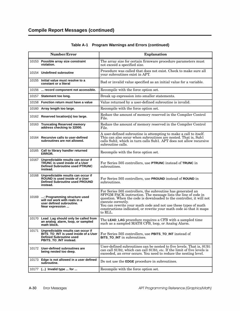
Error MessagesA-30 APT Programming Reference (Graphics/Math)
Compile Report Messages (continued)
Table A-1 Program Warnings and Errors (continued)
Number/Error Explanation
10153 Possible array size constraintviolation.
The array size for certain firmware procedure parameters mustnot exceed a specified size.
10154 Undefined subroutine Procedure was called that does not exist. Check to make sure allyour subroutines exist in APT.
10155 Initial value must resolve to aconstant or a literal Bad or invalid value specified as an initial value for a variable.
10156 ... record component not accessible. Recompile with the force option set.
10157 Statement too long. Break up expression into smaller statements.
10158 Function return must have a value Value returned by a user-defined subroutine is invalid.
10160 Array length too large. Recompile with the force option set.
10162 Reserved location(s) too large. Reduce the amount of memory reserved in the Compiler ControlFile.
10163 Truncating Reserved memoryaddress checking to 32000.
Reduce the amount of memory reserved in the Compiler ControlFile.
10164 Recursive calls to user-definedsubroutines are not allowed.
A user-defined subroutine is attempting to make a call to itself.This can also occur when subroutines are nested. That is, Sub1calls Sub2, which in turn calls Sub1. APT does not allow recursivesubroutine calls.
10165 Call to library handler returnedERROR. Recompile with the force option set.
10167 Unpredictable results can occur ifTRUNC is used inside of a UserDefined Subroutine used PTRUNCinstead.
For Series 505 controllers, use PTRUNC instead of TRUNC insubroutines.
10168 Unpredictable results can occur ifROUND is used inside of a UserDefined Subroutine used PROUNDinstead.
For Series 505 controllers, use PROUND instead of ROUND insubroutines.
10169 ...: Programming structure usedwill not work with reals in auser defined subroutine.Near expression ...
For Series 505 controllers, the subroutine has generated anSFPGM PACK instruction. The message lists the line of code inquestion. When the code is downloaded to the controller, it will notexecute correctly.You can rewrite your math code and not use these types of mathconstructions indicated, or rewrite your math code so that it mapsto RLL.
10170 Lead_Lag should only be called froman analog_alarm, loop, or sampledmath block.
The LEAD_LAG procedure requires a CFB with a sampled timesuch as a sampled MATH CFB, loop, or Analog Alarm.
10171 Unpredictable results can occur ifBITS_TO_INT is used inside of a UserDefined Subroutine usedPBITS_TO_INT instead.
For Series 505 controllers, use PBITS_TO_INT instead ofBITS_TO_INT in subroutines.
10172 User-defined subroutines arebeing nested too deep.
User-defined subroutines can be nested to five levels. That is, SUB1can call SUB2, which can call SUB3, etc. If the limit of five levels isexceeded, an error occurs. You need to reduce the nesting level.
10173 Edge is not allowed in a user definedsubroutine. Do not use the EDGE procedure in subroutines.
10177 (...) Invalid type ... for ... Recompile with the force option set.
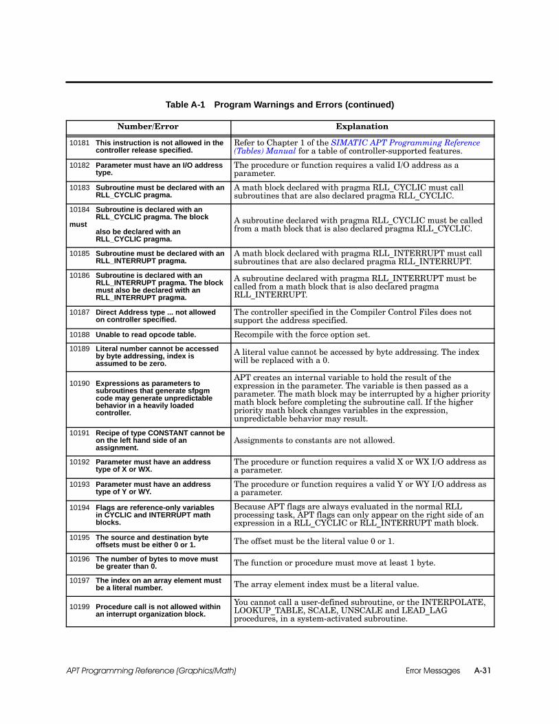
Error Messages A-31APT Programming Reference (Graphics/Math)
Table A-1 Program Warnings and Errors (continued)
Number/Error Explanation
10181 This instruction is not allowed in thecontroller release specified.
Refer to Chapter 1 of the SIMATIC APT Programming Reference(Tables) Manual for a table of controller-supported features.
10182 Parameter must have an I/O addresstype.
The procedure or function requires a valid I/O address as aparameter.
10183 Subroutine must be declared with anRLL_CYCLIC pragma.
A math block declared with pragma RLL_CYCLIC must callsubroutines that are also declared pragma RLL_CYCLIC.
10184 Subroutine is declared with anRLL_CYCLIC pragma. The block
mustalso be declared with anRLL_CYCLIC pragma.
A subroutine declared with pragma RLL_CYCLIC must be calledfrom a math block that is also declared pragma RLL_CYCLIC.
10185 Subroutine must be declared with anRLL_INTERRUPT pragma.
A math block declared with pragma RLL_INTERRUPT must callsubroutines that are also declared pragma RLL_INTERRUPT.
10186 Subroutine is declared with anRLL_INTERRUPT pragma. The blockmust also be declared with anRLL_INTERRUPT pragma.
A subroutine declared with pragma RLL_INTERRUPT must becalled from a math block that is also declared pragmaRLL_INTERRUPT.
10187 Direct Address type ... not allowedon controller specified.
The controller specified in the Compiler Control Files does notsupport the address specified.
10188 Unable to read opcode table. Recompile with the force option set.
10189 Literal number cannot be accessedby byte addressing, index isassumed to be zero.
A literal value cannot be accessed by byte addressing. The indexwill be replaced with a 0.
10190 Expressions as parameters tosubroutines that generate sfpgmcode may generate unpredictablebehavior in a heavily loadedcontroller.
APT creates an internal variable to hold the result of theexpression in the parameter. The variable is then passed as aparameter. The math block may be interrupted by a higher prioritymath block before completing the subroutine call. If the higherpriority math block changes variables in the expression,unpredictable behavior may result.
10191 Recipe of type CONSTANT cannot beon the left hand side of anassignment.
Assignments to constants are not allowed.
10192 Parameter must have an addresstype of X or WX.
The procedure or function requires a valid X or WX I/O address asa parameter.
10193 Parameter must have an addresstype of Y or WY.
The procedure or function requires a valid Y or WY I/O address asa parameter.
10194 Flags are reference-only variablesin CYCLIC and INTERRUPT mathblocks.
Because APT flags are always evaluated in the normal RLLprocessing task, APT flags can only appear on the right side of anexpression in a RLL_CYCLIC or RLL_INTERRUPT math block.
10195 The source and destination byteoffsets must be either 0 or 1. The offset must be the literal value 0 or 1.
10196 The number of bytes to move mustbe greater than 0. The function or procedure must move at least 1 byte.
10197 The index on an array element mustbe a literal number. The array element index must be a literal value.
10199 Procedure call is not allowed withinan interrupt organization block.
You cannot call a user-defined subroutine, or the INTERPOLATE,LOOKUP_TABLE, SCALE, UNSCALE and LEAD_LAGprocedures, in a system-activated subroutine.

Error MessagesA-32 APT Programming Reference (Graphics/Math)
Compile Report Messages (continued)
Table A-1 Program Warnings and Errors (continued)
Number/Error Explanation
10200 . . has no image register, operationhas no effect.
If you do not have the image register selected, you cannot do anIREAD or an IWRITE to the I/O point.
10201 Parameter . . . must be literal. For S5 controllers, specified parameter cannot be an expression orvariable.
10202 Parameter is out of range. One or more of the parameters has exceeded the allowable rangefor the instruction.
10203 Fast timer cannot be locallydeclared for specified controllertype.
You cannot locally declare a fast timer for S5.
11012 Reserved memory, controller type,or number of RCC cards havechanged resulting in change totranslated addresses.
Tags marked for translation to PCS will be allocated newaddresses due to changes since the last time the Build TranslateTable option was selected. Changes were made either in thecontroller type, in the number of RCC cards, or in these reservedmemory locations: K-Memory, V-Memory, number of loops, numberof analog alarms, number of timer/counters, number of retentiveCRs, or number of nonretentive CRs.
11013 Reserved memory and/or controllertype have changed resulting inchange to translated address
Tags marked for translation to PCS will be allocated newaddresses due to changes since the last time the Build TranslateTable option was selected. Changes were made either in thecontroller type or in these reserved memory locations: DB, DX,Flag, Timer and Counter.
11015 A previously translated unit hasbeen marked for compile againresulting in translated addresses tobe changed.
Tags marked for translation to PCS will be allocated newaddresses. This occurs when a unit that was at one time includedin a compile with the Build Translate Table option was at a latertime not included in a compile with the Build Translate Tableoption, but has now been re-included in the current compile.

Error Messages A-33APT Programming Reference (Graphics/Math)
Table A-1 Program Warnings and Errors (continued)
Number/Error Explanation
12000 Number of RCCs listed in ....An invalid number appears for the number of 560/560T565/565T/565P RCCs. 1, 2, 3, or 4 RCCs can be used; each RCC hastwo I/O channels.
12045 Out of retentive CRs. Symbol =... in ...
The APT program requires more retentive CRs than yourcontroller supports.If you receive this error for a 560/560T/565/565T/565P controller,be certain that the number of RCCs in your Compiler Control Fileindicates the correct number of RCCs in your controller.
If you receive this error for any controller, you must do one of thefollowing: Reduce the number of boolean variables (including arrays)
that are declared as retentive in your program. Reduce the amount of retentive CR memory reserved in the
Compiler Control File. For a 560/560T/565/565T/565P, you can increase the
number of RCCs in your system (maximum=4).
12046 Out of nonretentive CRs andunused I/O locations.Symbol = ... in ....
The APT program requires more non-retentive CRs than yourcontroller supports. If the compiler runs out of non-retentive CRs,it uses Ys that are unused after the last configured I/O point oneach channel.If you receive this error for a 560/560T/565/565T/565P controller,be certain that the number of RCCs in your Compiler Control Fileindicates the correct number of RCCs in your controller.If you receive this error for any controller, you must do one of thefollowing: Reduce the number of boolean variables (including arrays)
that are declared as non-retentive in your program. Reduce the amount of non-retentive CR memory reserved in
the Compiler Control File. Reduce the value of the last I/O module starting point on
each I/O channel (i.e., remove any gaps containing unused I/Oaddresses). This can be done in the I/O Module Editor and doesnot require the physical relocation of I/O modules.
For a 560/560T/565/565T/565P, you can increase thenumber of RCCs in your system (maximum=4).
12058 Cannot re-allocate address forstructure element x.
In certain instances when you do a force compile, or when anassembly force compile occurs, APT cannot fix the addresses ofBoolean elements in recipes that contain Boolean arrays. Whenthis occurs, the assembler generates error 12058 during programcompilation. You must then recompile your program withTranslate set to Yes and re-install your tags to the operatorstation.

Error MessagesA-34 APT Programming Reference (Graphics/Math)
Compile Report Messages (continued)
Table A-1 Program Warnings and Errors (continued)
Number/Error Explanation
12080 Program requires... words ofL-Memory. Max = ....
12081 Program requires... S-Memory.Max = ....
12082 Program requires... V-Memory.Max = ....
12083 Program requires... words ofK-Memory. Max = ....
12084 Program requires... one shots.Max = ....
12085 Program requires... tmr/ctr/dcatboxes. Max = ....
12086 Program requires... table moveboxes. Max = ....
12087 Program requires... shift boxes.Max = ....
12088 Program requires... drums.Max = ....
12090 Program using ... of invalidmemory type ... for currentcontroller type.
12114 Program requires... analogalarms. Max = ....
12115 Program requires... loops.Max = ....
12116 Program requires... RLLsubroutines. Max = ....
12117 Program requires... specialfunction programs. Max = ....
12118 Program requires... specialfunction subroutines. Max = ....
12119 Program requirements exceedavailable controller memory:
APT compiler cannot allocate the required amount of memory.Either there is an insufficient amount of memory in your controlleror you have attempted to use an APT operation not supported byyour controller. For example, for Series 505 controllers, SFPGMsare only supported by the 545, 545L, 555, 565/565T/565P, and the575, and any APT operation requiring an SFPGM can only be usedwith these controllers.
APT attempts to compile code for the controller indicated in theCompiler Control File. Check to make sure this file correctlyindicates the controller that you intend to use. The ControllerSupport section of the “APT Overview” Chapter in the SIMATICAPT Programming Reference (Tables) Manual lists which APTprogramming options are available on the supported controllers.
If you have not attempted to use an unsupported option for yourcontroller, be sure that the memory size in Compiler Control Filematches the memory size of controller. If this is the only error,deselect Force Compile in the Compiler Control File beforerecompiling.
If you still receive one of these errors, do one of the following: Reduce the general memory usage of your present program. Reduce the amount of reserved memory in the Compiler
Control File (as possible). Increase the amount of memory in your controller. For the
545-1101 and the 560/560T/565/565T/565P models, and the S5928B, you can add additional memory cards.
Do not compile a Debug version. Compiling a Debug versionuses more memory.

Error Messages A-35APT Programming Reference (Graphics/Math)
Table A-1 Program Warnings and Errors (continued)
Number/Error Explanation
PROFIBUS--DP Errors/Messages
12180 Non-numeric string “ ... ” notwithin comment.
Check the indicated file and line for a word outside of a comment.Words can only be within comments.
12181 Encountered end of file beforecomment termination.
Check the indicated file and line for a comment that was not closedby an ending symbol “}” or “*)”. This may occur on a line previousto the one reported.
12182 PROFIBUS--DP slave ... is invalid andmust be in range [n1 . . n2].
Check the indicated file and line for a slave number that is notwithin the required range.
12183 Channel ... is invalid and must bein range [n1 . . n2].
Check the indicated file and line for a channel number that is notwithin the required range.
12184 Base ... is invalid and must be inrange [n1 . . n2].
Check the indicated file and line for a base number that is notwithin the required range.
12185 Slot ... is invalid and must be in range[n1 . . n2].
Check the indicated file and line for a slot number that is notwithin the required range.
12186 PROFIBUS--DP module ... is invalidand must be in range [n1 . . n2].
Check the indicated file and line for a module number that is notwithin the required range.
12187 Required module, channel and basemissing.
Check the indicated file and line for a missing module number,channel number, and base number.
12188 Required channel and base missing. Check the indicated file and line for a missing channel number andbase number.
12189 Required base missing. Check the indicated file and line for a missing base number.
12190 ... slots have already beenspecified. Slot ... is extraneous.
Check the indicated file and line for extra slot numbers that arenot needed.
12191 ... slots have already beenspecified, but only ... slots areavailable.
Check the indicated file and line. There are too many slotsrequested and not enough available.
12192 PROFIBUS--DP slave ... , module ...has already been used.
Check the indicated file and line. The slave module specified waspreviously used in this file.
12194 Invalid PROFIBUS starting addressfor ... .
The indicated slave module was not given a starting address in themodule editor. Please verify that this slave and module areassociated with a channel, base, and slot and given a valid startingaddress in the module editor.

Error MessagesA-36 APT Programming Reference (Graphics/Math)
Table A-1 Program Warnings and Errors (continued)
Error Explanation
PROFIBUS--DP Errors/Messages
12195 File or path name not found EXPORT.2BF did not exist in the /PRR directory.
Disk full Disk containing APT was full.
Slave ... in APT but not in COMPROFIBUS
The indicated slave was in the PROFIBUS.CFG file, but not inthe COM PROFIBUS export file.
Slave ... in COM PROFIBUS but not inAPT
The indicated slave was in the COM PROFIBUS export file, butnot in the PROFIBUS.CFG file.
Slave ..., Module ... in APT but not inCOM PROFIBUS
The indicated slave module was in the PROFIBUS.CFG file, butnot in the COM PROFIBUS export file.
Slave ... , Module ... in COM PROFIBUSbut not in APT
The indicated slave module was in the COM PROFIBUS exportfile, but not in the PROFIBUS.CFG file.
Slave ... , Module ... APT: ,nX nY nWXnWY, COM PB: nX nY nWX nWY
There is a mismatch between PROFIBUS.CFG and the COMPROFIBUS data for this slave module.
12198 ... is not an integer in range [0 . . 32767] Check the indicated file and line for an integer that is outsidethe required range.
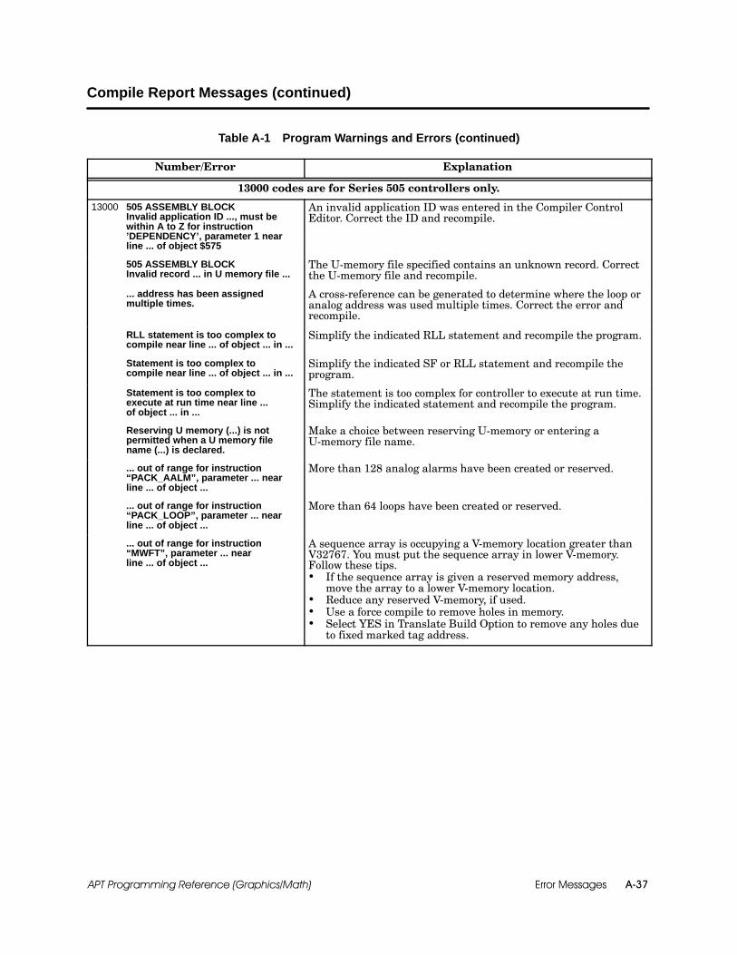
Error Messages A-37APT Programming Reference (Graphics/Math)
Compile Report Messages (continued)
Table A-1 Program Warnings and Errors (continued)
Number/Error Explanation
13000 codes are for Series 505 controllers only.
13000 505 ASSEMBLY BLOCKInvalid application ID ..., must bewithin A to Z for instruction’DEPENDENCY’, parameter 1 nearline ... of object $575
An invalid application ID was entered in the Compiler ControlEditor. Correct the ID and recompile.
505 ASSEMBLY BLOCKInvalid record ... in U memory file ...
The U-memory file specified contains an unknown record. Correctthe U-memory file and recompile.
... address has been assignedmultiple times.
A cross-reference can be generated to determine where the loop oranalog address was used multiple times. Correct the error andrecompile.
RLL statement is too complex tocompile near line ... of object ... in ...
Simplify the indicated RLL statement and recompile the program.
Statement is too complex tocompile near line ... of object ... in ...
Simplify the indicated SF or RLL statement and recompile theprogram.
Statement is too complex toexecute at run time near line ...of object ... in ...
The statement is too complex for controller to execute at run time.Simplify the indicated statement and recompile the program.
Reserving U memory (...) is notpermitted when a U memory filename (...) is declared.
Make a choice between reserving U-memory or entering aU-memory file name.
... out of range for instruction“PACK_AALM”, parameter ... nearline ... of object ...
More than 128 analog alarms have been created or reserved.
... out of range for instruction“PACK_LOOP”, parameter ... nearline ... of object ...
More than 64 loops have been created or reserved.
... out of range for instruction“MWFT”, parameter ... nearline ... of object ...
A sequence array is occupying a V-memory location greater thanV32767. You must put the sequence array in lower V-memory.Follow these tips. If the sequence array is given a reserved memory address,
move the array to a lower V-memory location. Reduce any reserved V-memory, if used. Use a force compile to remove holes in memory. Select YES in Translate Build Option to remove any holes due
to fixed marked tag address.

Error MessagesA-38 APT Programming Reference (Graphics/Math)
Table A-1 Program Warnings and Errors (continued)
Number/Error Explanation
14006 Potential PCS/controller mismatch.Reinstall translator tags to correct.
This is a warning. It means you have changed your marked tags,but not installed them on PCS.
14008 Tag...in...cannot be translated. (If I/Opoint, try marking ’IMAGEREGISTER’ field) Memory Type = . . .
This tag cannot be translated to PCS. PCS can only translate I, Q,F, D, DW, DD, TMR, and CTR. If the tag is an I/O point, then markthe image register field on the I/O Form.
14012 DO NOT ATTEMPT TO INSTALLTAGS.Tag ... in ... has an address out ofrange, ..., which cannot betranslated to TISTAR Release 1.x orTISTAR 2.x.
For Series 505 controllers, TISTAR Releases 1.x and 2.x did notsupport V- and K-memory addresses above 65536. The followingare possible solutions:— Reduce the amount of any reserved V- and K-memory.— Make sure any user-assigned addresses are below this value if
the object is marked for tag translate.— Recompile with a YES Translate Build to move all translated
tags to lower memory.
14025 Secondary name was not given. No secondary name was given in the Compiler Control File. Entera name and recompile.
14028 PCS does not support range spanof 0 for ...
Change the ranges for the given object so that the range span isnot 0.
14031 Possible overflow of RBE memory.RBE Memory Reserved = ... Kbytes.Estimated RBE MemoryUsage = ... Kbytes.
An estimate of RBE memory usage has been calculated and isgreater than the amount reserved. Refer to the chapter on “APTand the PCS Operator Interface” in the SIMATIC APTApplications Manual and check the usage again.
14032 RBE memory ... Kbytes is out ofrange. Range = 0 to ....
Reduce the amount of RBE memory reserved in the CompilerControl File.
14047 The OUT attribute for the AO tag ...had an initial value of ... which is notwithin the high/low range of ... Theinitial value being translated to PCSwas adjusted to ...
The OUT attribute for an AO tag had an invalid initial value. Ifyou do not want the initial value assigned by APT, you mustunmark the tag and either change the high and low ranges or elsechange the initial value. You can then remark the tag andrecompile.

Error Messages A-39APT Programming Reference (Graphics/Math)
Compile Report Messages (continued)
Table A-1 Program Warnings and Errors (continued)
Number/Error Explanation
15000 codes are for S5 controllers only
15007 S5 ASSEMBLY BLOCKSyntax error near token “A(” nearline ... of object ... in ...
Either a subroutine is named A or the assembly code is incorrect.Either a subroutine is named AN or the assembly code is incorrect.Either a subroutine is named O or the assembly code is incorrect.
S5 ASSEMBLY BLOCKSyntax error near token “AN(” nearline ... of object ... in ...
Either a subroutine is named O or the assembly code is incorrect.Either a subroutine is named ON or the assembly code is incorrect.
If you receive any of these errors, do one of the following: If a subroutine exists with the name A AN O or ON rename
S5 ASSEMBLY BLOCKSyntax error near token “O(” nearline ... of object ... in ...
S5 ASSEMBLY BLOCKSyntax error near token “ON(” nearline ... of object ... in ...
If a subroutine exists with the name A, AN, O, or ON, renamethe subroutine and recompile.
If in-line assembly code is being used, check for the correctsyntax and recompile.
Use the Extract utility as described in the DOS Utilitiesappendix section of the SIMATIC APT User Manual todetermine if the generated code is correct for thedetermine if the generated code is correct for thegiven object.
16025 Direct address % . . . is not in thereserved memory range near line. . . of object . . . in . . .
The direct address that is called out is not in the reserved memoryin the Compiler Control File. Check the items that are reserved inthe Compiler Control File.
16035 S5 ASSEMBLY BLOCK. . . block is out of range. Range = . . .to . . . near line . . . of object . . . in . . .
DRs or DXs are out of range. The range is 0 to 255.
16038 FB/FX . . . is too large (. . . words) forpsect . . . near line . . . of object . . .in . . .
The FB or FX is too large to fit in the given object. Reduce yourcode for that given object.
16045 Statement is too complex to executeat run time, near line ... of object ...in ...
The statement is too complex for the controller to execute at runtime. Simplify the indicated statement and recompile the program.
16060 Symbol . . . not retrieved in . . . Make sure your symbol is declared.
16071 Invalid index . . . for . . . . Range is . . .to . . .Invalid reserved memory . . . for . . .
The index given is out of range for that type of memory.Keep your indexes within the defined range.
16075 Out of . . . for object . . .
The type of memory has been exceeded. In order to get morememory, you can reduce reserved memory for the given memorytype, perform a force compile to compress any deleted memory, orreduce your code for the given object.
16078 No more memory locations existfor. . . in . . .
Reduce any reserved memory in which the given declaration couldbe allocated. Perform a force compile to compress any holes thatmight exist.

Error MessagesA-40 APT Programming Reference (Graphics/Math)
A.4 Translate/Download/Debug Error Messages
You may receive one of the following error messages during translation orprogram download. If you cannot correct the problem by following thesuggestions in Table A-2, or if you receive a message not on this list, call(800) 333--7421 in the U.S.A., or 49--911--895--7000 outside the U.S.A., forassistance.
Table A-2 Translate, Download, and Debug Errors
Translate Errors
Message Cause Corrective Action
Translation failed with tagvalidation.
The tag data conflicts with thePCS configuration.
Examine the TRANSLAT.RPT file in the\APT\PROGRAM\program_name\PRRsubdirectory for error messages.
PCS communications error.Communications between theremote computer and the PCSsystem are not available or arebroken.
Check cabling between the remote computerand PCS system; check the communicationscard installation; be certain that youfollowed the setup and translate proceduresdescribed in this manual.
PCS does not respond.Communications between theremote computer and the PCSsystem are not available or arebroken.
Check cabling between the remote computerand PCS system; check the communicationscard installation; be certain that youfollowed the setup and translate proceduresdescribed in this manual.
PCS APT server does notrespond.
APT cannot communicate withthe APT server task running onthe PCS node.
Be certain that you followed the setup andtranslate procedures described in thismanual.
Insufficient PCS userprivilege.
The user does not have the PCSprivilege to translate tags.
Use User ID with appropriate securityprivilege.
PCS secondary name notfound.
The secondary name does notexist in PCS.
Use correct secondary name, or changePCS configuration.
Cannot open file on OSU.The remote computer cannotaccess the file INSTALL.TAG orcannot write to the fileTRANSLAT.RPT.
Be certain that the subdirectory\APT\PROGRAM\program_name\PRR existson the remote computer and that the fileINSTALL.TAG is located in thesubdirectory\APT\PROGRAM\program_name. Be certainthat the file TRANSLAT.RPT is notwrite-protected.
Cannot open file on PCS.Cannot open a file in theusr/tistar/data/tmp directory onthe PCS system.
This subdirectory is created when youinstall PCS software. If this subdirectoryhas been removed, you can create it again.Be certain that it contains nowrite-protected files.
Cannot translate. PCS mustbe in offline state. PCS is not in the Offline state. Set PCS to the Offline state.
OSU disk access error. Unable to read the hard disk onthe remote computer.
Check the hard disk on the remotecomputer for errors, or to see if it is full.
Fatal Error—APT file hasincorrect or missinginformation.
TISTAR Model 20 TRANS doesnot know to interpret someinformation in theINSTALL.TAG file.
Check for UNIT tags, TEXT tags, or othertag types not supported in TISTARRel. 1.3.x.
Overview

Error Messages A-41APT Programming Reference (Graphics/Math)
Translate/Download Error Messages (continued)
Table A-2 Translate, Download, and Debug Errors (continued)
Translate Errors
Message Cause Corrective Action
PCS error occurredinstalling tags.
An error occurred during theinstall phase of tag translation.
Check the file TRANSLAT.RPT formessages.
PCS tag configurationcurrently active.
The tag configurator or tagtranslator is already running.
Be certain that the tag configuratorsoftware is not running on the PCS system,i.e., no one is configuring PCS tags.
Download Errors
Message Cause Corrective Action
Taskcode error detected. The controller returned the errorthat follows.
Refer to your controller user manual fordetails.
NIM error detected. The NIM returned the error thatfollows. Refer to your NIM user manual for details.
PCS communications error.Communications between theAPT node and the PCS node arenot available or are broken.
Check cabling between the APT node andPCS node; check the communications cardinstallation; be certain that you followed thesetup and translate procedures described inthis manual.
PCS is not responding.Communications between theAPT node and the PCS node arenot available or are broken.
Check cabling between the APT node andPCS node; check the communications cardinstallation; be certain that you followed thesetup and translate procedures described inthis manual.
Unable to initiate PCS APTserver.
APT cannot communicate withthe APT server task running onthe PCS node.
Be certain that you followed the setup andtranslate procedures described in thismanual.
TISTAR-TIWAYcommunications error.
Communications between theDEU and the NIM are notavailable or are broken.
Check TIWAY cabling.
PC-controllercommunications error.
Direct link communicationsbetween the remote computerand the controller are notavailable or are broken.
Check cabling. Be certain that the baud rateand serial communications port (specifiedwhen you set up APT) are correct.
PCS must be in operatestate. PCS is not in the Operate state. Set PCS to the Operate state.
Cannot set baud rate. The specified port is invalid forcommunications.
Be certain that the baud rate and serialcommunications port (specified when youset up APT) are correct.
User is not privileged.The user does not have thePCS privilege to download aprogram to the controller.
Use a User ID with appropriate securityprivilege.
Secondary name not found. The secondary name does notexist in the PCS database.
Use the correct secondary name, or changePCS configuration.

Error MessagesA-42 APT Programming Reference (Graphics/Math)
Table A-2 Translate, Download, and Debug Errors (continued)
Download Errors
Message Cause Corrective Action
Secondary is not connected. The secondary is not physicallyconnected to the PCS system. Connect the secondary to the PCS system.
Secondary is of wrong type. The APT program does not matchthe connected secondary.
Recompile APT for the correct secondary, orconnect the correct secondary to thePCS system.
Last compile did notcomplete.
The remote computer cannotaccess the file RETURN orcompile did not complete.
Be certain that the subdirectory\APT\PROGRAM\program_name\MAKEexists on the remote computer and that itcontains the file RETURN. Also check thatyou have a successfully compiled program.
Cannot access APT file.The remote computer hard diskmay be bad, or the download filesare corrupted.
Use the DOS command CHKDSK to checkthe hard disk and files.Be certain that the subdirectory\APT\PROGRAM\program_name\MAKEexists on the remote computer and that itcontains the file RETURN.Be certain that the subdirectory\APT\PROGRAM\program_name exists onthe remote computer and that it containsthe OBJECT.DWN and VERSION.DWNfiles for each unit that is compiled.
Current download aborted. The user aborted the download.Note that the controller may contain aninvalid program when you abort thedownload.
Program not found.The program name that youspecified for downloading was notfound.
Use the correct program name.
Download file not found. The file OBJECT.DWN ismissing.
Be certain that the file OBJECT.DWNexists in the subdirectory\APT\PROGRAM\program_name.
No loop card on controller.The controller does not processloop, analog alarm, or SpecialFunction Program information.
Install a 545, 545L, 555, 565/565T/565P, or a575; or compile for another type ofcontroller.
Program too large. The controller memory cannothold the program.
Reduce the size of the program, or increasecontroller memory.
Not enough RCCs oncontroller.
More RCCs were specified in theAPT compile file than areactually installed (560/560T/565/565T/565P only).
Specify fewer RCCs in the APT compile file,or install additional RCCs.
APT locked from writing tocontroller.
Certain download functions havebeen limited.
See the last page of the Release Notes,“Remove Debug Functionality.”
Debug Errors
Message Cause Corrective Action
Debug out of variablestorage space. Too many incremental compiles. Force compile.

Error Messages A-43APT Programming Reference (Graphics/Math)
A.5 Archive/Restore Error Messages
You may receive one of the following error messages while archiving orrestoring a program. If you cannot correct the problem by following thesuggestions in Table A-3, and need assistance, call (800) 333--7421 in theU.S.A., or 49--911--895--7000 outside the U.S.A.
The Archive and Restore processes depend on the environment variablesAPT_COMMON, APT_DB, and APT_LOCAL. If these variables are not set, or ifthey are set but do not specify a disk drive, then APT, APTARCH, andAPTREST must be executed from the drive that contains the APTinformation provided in the standard installation directories \APT\TEXT,\APT\DATABASE, and \APT\PROGRAM.
Table A-3 Archive and Restore Errors
ArchiveError
RestoreError Error Message Explanation/Comments
nArchive record sequenceerror
The data records in the specified archive file are out ofsequence. The archive files are either out of order orcorrupted. For archives on diskette, be sure that the disksare inserted in the proper order.
n n Cancelled by user The Archive or Restore process was aborted by the user.
n Cannot delete directory
An attempt to delete the program information from theAPT program directory has failed. Be sure that no files inthe program directory have the read-only attribute set.Verify that APT is installed correctly and that allappropriate environment variables have been set. Refer tothe “Overview” information that precedes this table.
nCannot make programdirectory
An attempt to create a program directory has failed.Verify that APT is properly installed and that all APTenvironment variables being used, especially APT_LOCAL,are properly set. Refer to the “Overview” information thatprecedes this table.
Be sure that the disk that holds the APT programdirectory is not full. See the “Disk is full” errordescription.
There may be insufficient memory for this operation to becompleted properly. See “Insufficient memory” errordescription.
n nCannot open/readARCCRC.DAT file
The specified file cannot be found. Verify that APT isproperly installed and that all APT environmentvariables being used, especially APT_COMMON, areproperly set. Refer to the “Overview” information thatprecedes this table.
nCannot open/read archivefile
An attempt to open or read from the<program_name>.<number> file has failed. Thespecified archive file does not exist, is damaged, or is not avalid program archive file. Be sure that the path and file(program) name are valid. For archives on diskette, besure to insert the diskettes in the proper order.
Overview

Error MessagesA-44 APT Programming Reference (Graphics/Math)
Table A-3 Archive and Restore Errors (continued)
ArchiveError
RestoreError Error Message Explanation/Comments
nCannot open/readARCLIST.DAT file
The specified file cannot be found. Verify that APT isproperly installed and that all APT environmentvariables being used, especially APT_COMMON, areproperly set. Refer to the “Overview” information thatprecedes this table.
nCannot open/read nextarchive file
An attempt to open or read from the next<program_name>.<number> file has failed. Thespecified archive file does not exist, is damaged, or is not avalid program archive file. Be sure that the path and file(program) name are valid. For archives on diskette, besure that the disks are inserted in the proper order.
nCannot open/write archivefile
An attempt to open or to write to the<program_name>.<number> file has failed. If thespecified file was created by a previous archive, be surethat the file’s read-only attribute is not set. If the target isa diskette, be sure that it is not write-protected. Be surethat the target disk is not full. See the “Disk is full” errordescription.
nCannot open/write programfile
An attempt to open (create) or write to a program file hasfailed. Verify that APT is properly installed and that allAPT environment variables being used, especiallyAPT_LOCAL, are properly set. Refer to the “Overview”information that precedes this table.
Be sure that the disk that holds the APT programdirectory is not full. See the “Disk is full” errordescription.
There may be insufficient memory for this operation to becompleted properly. See “Insufficient memory” errordescription.
nCannot write record countto archive file
An attempt to write this archive’s total record count to the<program_name>.1 file has failed. If target is a diskette,be sure that it is not write-protected.
Be sure that the target disk is not full. See “Disk is full”error description.
nCRC error during fileexpansion
A data record in the specified archive file contains aninvalid CRC value. The archive file is either incomplete orcorrupted; successful restoration is unlikely.
n Database conversion error
An error occurred during conversion of the restoredprogram to the current database format. If restored fromthe APT hierarchy, examine the TMSTDOUT.LOG file formore information.
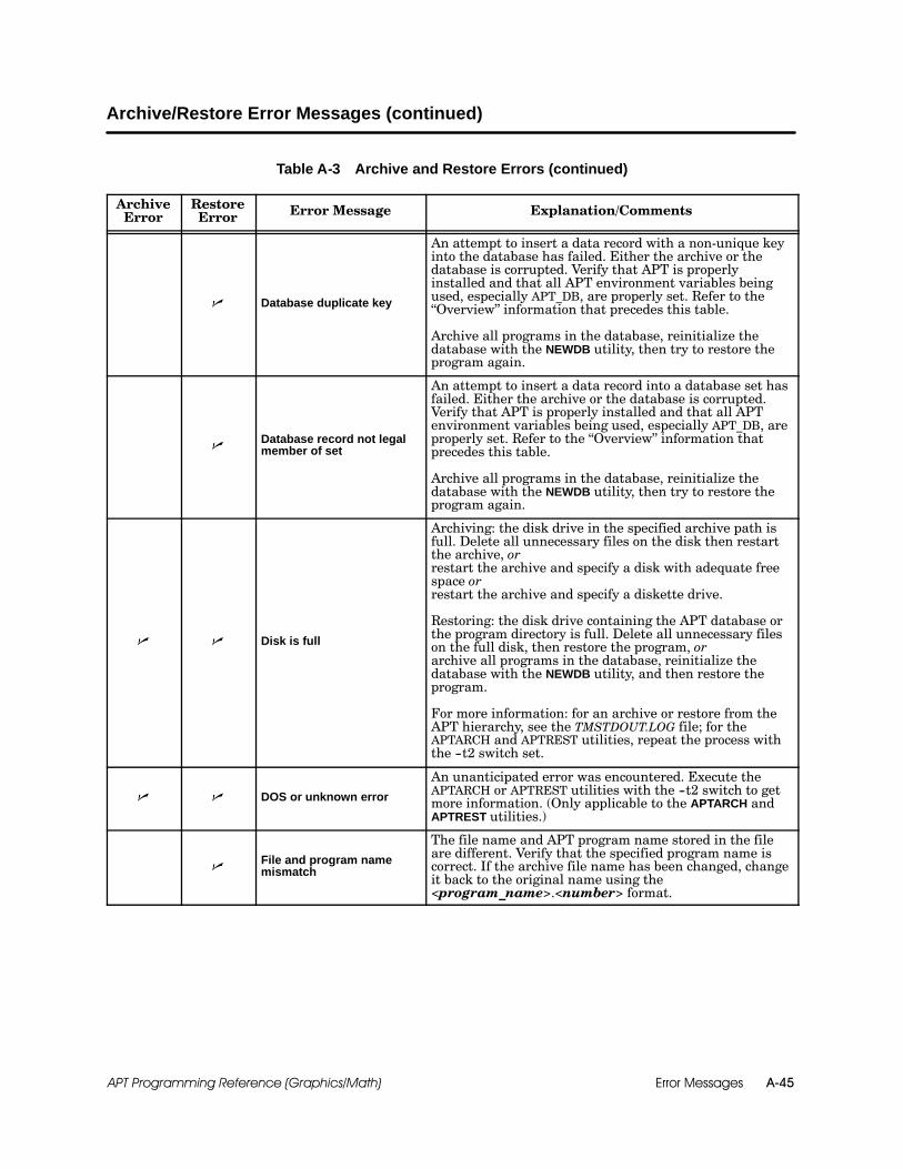
Error Messages A-45APT Programming Reference (Graphics/Math)
Archive/Restore Error Messages (continued)
Table A-3 Archive and Restore Errors (continued)
ArchiveError
RestoreError Error Message Explanation/Comments
n Database duplicate key
An attempt to insert a data record with a non-unique keyinto the database has failed. Either the archive or thedatabase is corrupted. Verify that APT is properlyinstalled and that all APT environment variables beingused, especially APT_DB, are properly set. Refer to the“Overview” information that precedes this table.
Archive all programs in the database, reinitialize thedatabase with the NEWDB utility, then try to restore theprogram again.
nDatabase record not legalmember of set
An attempt to insert a data record into a database set hasfailed. Either the archive or the database is corrupted.Verify that APT is properly installed and that all APTenvironment variables being used, especially APT_DB, areproperly set. Refer to the “Overview” information thatprecedes this table.
Archive all programs in the database, reinitialize thedatabase with the NEWDB utility, then try to restore theprogram again.
n n Disk is full
Archiving: the disk drive in the specified archive path isfull. Delete all unnecessary files on the disk then restartthe archive, orrestart the archive and specify a disk with adequate freespace orrestart the archive and specify a diskette drive.
Restoring: the disk drive containing the APT database orthe program directory is full. Delete all unnecessary fileson the full disk, then restore the program, orarchive all programs in the database, reinitialize thedatabase with the NEWDB utility, and then restore theprogram.
For more information: for an archive or restore from theAPT hierarchy, see the TMSTDOUT.LOG file; for theAPTARCH and APTREST utilities, repeat the process withthe --t2 switch set.
n n DOS or unknown error
An unanticipated error was encountered. Execute theAPTARCH or APTREST utilities with the --t2 switch to getmore information. (Only applicable to the APTARCH andAPTREST utilities.)
nFile and program namemismatch
The file name and APT program name stored in the fileare different. Verify that the specified program name iscorrect. If the archive file name has been changed, changeit back to the original name using the<program_name>.<number> format.
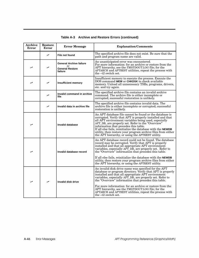
Error MessagesA-46 APT Programming Reference (Graphics/Math)
Table A-3 Archive and Restore Errors (continued)
ArchiveError
RestoreError Error Message Explanation/Comments
n File not found The specified archive file does not exist. Be sure that thepath and program name are valid.
n n
General Archive failureor
General Restorefailure
An unanticipated error was encountered.For more information: for an archive or restore from theAPT hierarchy, see the TMSTDOUT.LOG file; for theAPTARCH and APTREST utilities, repeat the process withthe --t2 switch set.
n n Insufficient memory
Insufficient memory to execute the process. Execute theDOS command MEM or CHKDSK to check availablememory. Unload all unnecessary TSRs, programs, drivers,etc. and try again.
nInvalid command in archivefile
The specified archive file contains an invalid archivecommand. The archive file is either incomplete orcorrupted; successful restoration is unlikely.
n Invalid data in archive fileThe specified archive file contains invalid data. Thearchive file is either incomplete or corrupted; successfulrestoration is unlikely.
n Invalid database
An APT database file cannot be found or the database iscorrupted. Verify that APT is properly installed and thatall APT environment variables being used, especiallyAPT_DB, are properly set. Refer to the “Overview”information that precedes this table.If all else fails, reinitialize the database with the NEWDButility, then restore your program archive files from eitherthe APT hierarchy, or using the APTREST utility.
n Invalid database record
An APT database record could not be found. The databaserecord may be corrupted. Verify that APT is properlyinstalled and that all appropriate APT environmentvariables, especially APT_DB, are properly set. Refer tothe “Overview” information that precedes this table.
If all else fails, reinitialize the database with the NEWDButility, then restore your program archive files from eitherthe APT hierarchy, or using the APTREST utility.
n n Invalid disk drive
An invalid disk drive name was specified for the APTdatabase or program directory. Verify that APT is properlyinstalled and that all appropriate APT environmentvariables, especially APT_DB, are properly set. Refer tothe “Overview” information that precedes this table.
For more information: for an archive or restore from theAPT hierarchy, see the TMSTDOUT.LOG file; for theAPTARCH and APTREST utilities, repeat the process withthe --t2 switch set.
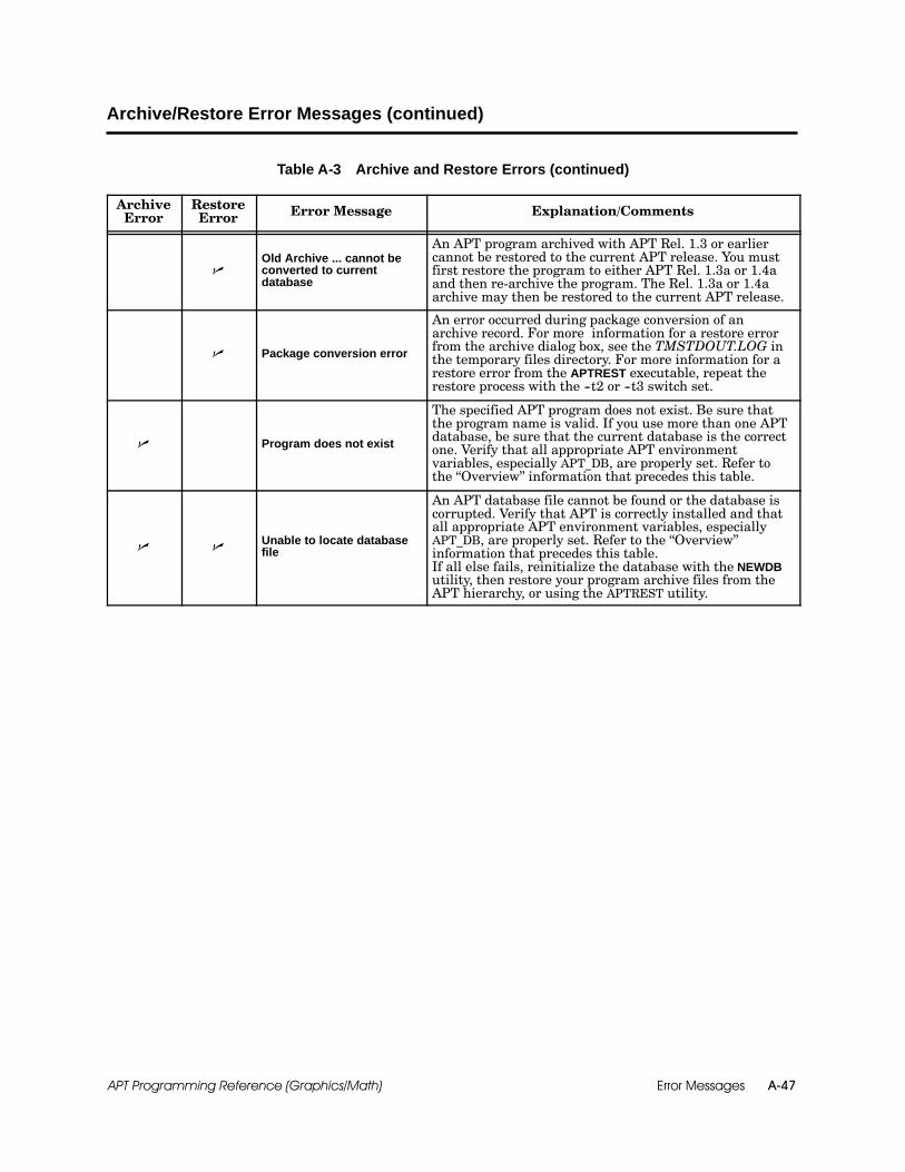
Error Messages A-47APT Programming Reference (Graphics/Math)
Archive/Restore Error Messages (continued)
Table A-3 Archive and Restore Errors (continued)
ArchiveError
RestoreError Error Message Explanation/Comments
nOld Archive ... cannot beconverted to currentdatabase
An APT program archived with APT Rel. 1.3 or earliercannot be restored to the current APT release. You mustfirst restore the program to either APT Rel. 1.3a or 1.4aand then re-archive the program. The Rel. 1.3a or 1.4aarchive may then be restored to the current APT release.
n Package conversion error
An error occurred during package conversion of anarchive record. For more information for a restore errorfrom the archive dialog box, see the TMSTDOUT.LOG inthe temporary files directory. For more information for arestore error from the APTREST executable, repeat therestore process with the --t2 or --t3 switch set.
n Program does not exist
The specified APT program does not exist. Be sure thatthe program name is valid. If you use more than one APTdatabase, be sure that the current database is the correctone. Verify that all appropriate APT environmentvariables, especially APT_DB, are properly set. Refer tothe “Overview” information that precedes this table.
n nUnable to locate databasefile
An APT database file cannot be found or the database iscorrupted. Verify that APT is correctly installed and thatall appropriate APT environment variables, especiallyAPT_DB, are properly set. Refer to the “Overview”information that precedes this table.If all else fails, reinitialize the database with the NEWDButility, then restore your program archive files from theAPT hierarchy, or using the APTREST utility.

Error MessagesA-48 APT Programming Reference (Graphics/Math)
A.6 DOS Operating System Error Messages
The DOS operating system may generate an error code when you validate orcompile an APT program. A DOS error code is listed in a compile or validatereport as the term Errno = nn. The nn is defined in Table A-4. Refer to thedocumentation for your DOS operating system for corrective measures. Ifyou cannot correct the problem, or if you receive a message not on this list,call (800) 333--7421 in the U.S.A., or 49--911--895--7000 outside the U.S.A.,for assistance.
The two error codes most commonly reported are #02 and #24.
Errno = 02 usually means that a file or subdirectory has been deleted.
Errno = 24 usually means that insufficient files have been specified inthe CONFIG.SYS file.
Table A-4 DOS Error Messages
Code Meaning Code Meaning
--1 Operating system error 18 Cross-device link
01 User is not owner 19 No such device
02 No such file or directory 20 Is not a directory
03 No such process 21 Is a directory
04 Interrupted system call 22 Invalid argument
05 I/O error 23 No more files (system)
06 No such device or address 24 No more files (process)
07 Arg list is too long 25 Not a terminal
08 Exec format error 26 Text file is busy
09 Bad file number 27 File is too large
10 No child process 28 No space left
11 No more processes allowed 29 Seek issued to pipe
12 No memory available 30 Read-only file system
13 Access denied 31 Too many links
14 Bad address 32 Broken pipe
15 Bulk device required 33 Math function argument error
16 Resource is busy34 Math function result is out
17 File already exists34 Math function result is out
of range
Direct Memory Addressing B-1APT Programming Reference (Graphics/Math)
Appendix B
Direct Memory Addressing
B.1 Types of Direct Memory Addressing B-2. . . . . . . . . . . . . . . . . . . . . . . . . . . . . . . . . . . . . . . . . . . . .Overview B-2. . . . . . . . . . . . . . . . . . . . . . . . . . . . . . . . . . . . . . . . . . . . . . . . . . . . . . . . . . . . . . . . . . . . . . .Availability B-2. . . . . . . . . . . . . . . . . . . . . . . . . . . . . . . . . . . . . . . . . . . . . . . . . . . . . . . . . . . . . . . . . . . . . .Status Words (Series 505 only) B-2. . . . . . . . . . . . . . . . . . . . . . . . . . . . . . . . . . . . . . . . . . . . . . . . . . . .System Data Area (RS) (S5 only) B-2. . . . . . . . . . . . . . . . . . . . . . . . . . . . . . . . . . . . . . . . . . . . . . . . . .Temporary Variables (Series 505 only) B-3. . . . . . . . . . . . . . . . . . . . . . . . . . . . . . . . . . . . . . . . . . . . .Reserved Memory B-3. . . . . . . . . . . . . . . . . . . . . . . . . . . . . . . . . . . . . . . . . . . . . . . . . . . . . . . . . . . . . . .
B.2 Using Direct Addresses (Series 505 Controllers) B-4. . . . . . . . . . . . . . . . . . . . . . . . . . . . . . . . . .Reserved Memory for Series 505 B-4. . . . . . . . . . . . . . . . . . . . . . . . . . . . . . . . . . . . . . . . . . . . . . . . . .Other Reserved Locations B-7. . . . . . . . . . . . . . . . . . . . . . . . . . . . . . . . . . . . . . . . . . . . . . . . . . . . . . . .Direct Addressing Guidelines for Series 505 Controllers B-10. . . . . . . . . . . . . . . . . . . . . . . . . . . . . .
B.3 Using Direct Addresses (S5 Controllers) B-11. . . . . . . . . . . . . . . . . . . . . . . . . . . . . . . . . . . . . . . . .Reserved Memory for S5 Controllers B-11. . . . . . . . . . . . . . . . . . . . . . . . . . . . . . . . . . . . . . . . . . . . . . .Direct Addressing Guidelines for S5 Controllers B-16. . . . . . . . . . . . . . . . . . . . . . . . . . . . . . . . . . . . . .
Direct Memory AddressingB-2 APT Programming Reference (Graphics/Math)
B.1 Types of Direct Memory Addressing
APT allows you to access memory addresses directly by using a percent sign(%) prefix. The types of direct memory addressing available depend on thekind of controller you have.
Status Word memory Allows you to read status words that containoperational information about your Series 505 controller.
System Data Area (RS) memory Allows you to read the internalsystem parameters that contain operational information about your S5controller.
Temporary (SFPGM) memory variables Allow you to use memoryspace only while a math block is executing.
Reserved memory Allows you to use memory locations that youreserve before compiling the program.
Status word memory and temporary (SFPGM) memory variables aresupported for Series 505 controllers only. System Data Area (RS) memory issupported for S5 controllers only. Reserved memory is supported for bothSeries 505 and S5 controllers.
If you have a Series 505 controller, APT allows you to read Status Words byusing the %STW address as a variable. For example, %STW1 allows you todirectly access the information in Status Word 1. For information about themeaning of the status words, see the manual that comes with your Series505 controller.
If you have an S5 controller, APT allows you to read RS words by using the%RSW address as a variable. For example, %RSW14 on a 928B allows youto directly access the information in RS14, which is the base address of theflag area. For a 948U/R, %RS9.0 allows you to directly access the bitinformation in RS9.0, which is the QVZ test bit. For more information aboutthe RS memory area, see the manual that comes with your S5 controller.
Overview
Availability
Status Words(Series 505 only)
System DataArea (RS)(S5 only)

Direct Memory Addressing B-3APT Programming Reference (Graphics/Math)
If you have a Series 505 controller, APT allows you to access 16 controllermemory locations that are available for the temporary storage of values.These temporary variables are available only within an SFPGM math block,which is supported by the 545, 555, 565, 565T, 565P, and 575 controllers.The values remain valid only while the math block is executing.
When you assign an integer value to temporary memory, the valueoccupies the indicated location: %T13 := 5 assigns the value of 5 tomemory location T13 (Figure B-1).
NOTE: Assign values only to T-Memory locations T11--T16. APT and thecontroller use locations T1--T10.
When you assign a real value to temporary memory, place a period atthe end of the variable name. A real value occupies the indicatedlocation and the next consecutive memory location: %T14. := 6.0assigns the value of 6.0 to memory locations T14 and T15 as illustratedin Figure B-1.
NOTE: Do not assign a real value to %T16 because only one memorylocation is available at that address.
%T1
%T2
%T3
%T4
%T5
%T6
%T7
%T8
%T9
%T10
%T11
%T12
%T13
%T14
%T15
%T16
%T13 accesses integer value stored in memory location T13
%T14. accesses real value stored in memory locations T14 and T15
* Reserved for APT and controller functions.
* 5
6.0*
*
*
*
*
*
*
*
*
Figure B-1 Using Temporary Memory (Series 505 only)
For both controller families, APT permits you to reserve controller memory.See Section B.2 for a discussion of reserved memory and direct addressingfor Series 505 controllers. See Section B.3 for a discussion of reservedmemory and direct addressing for S5 controllers.
TemporaryVariables(Series 505 only)
Reserved Memory
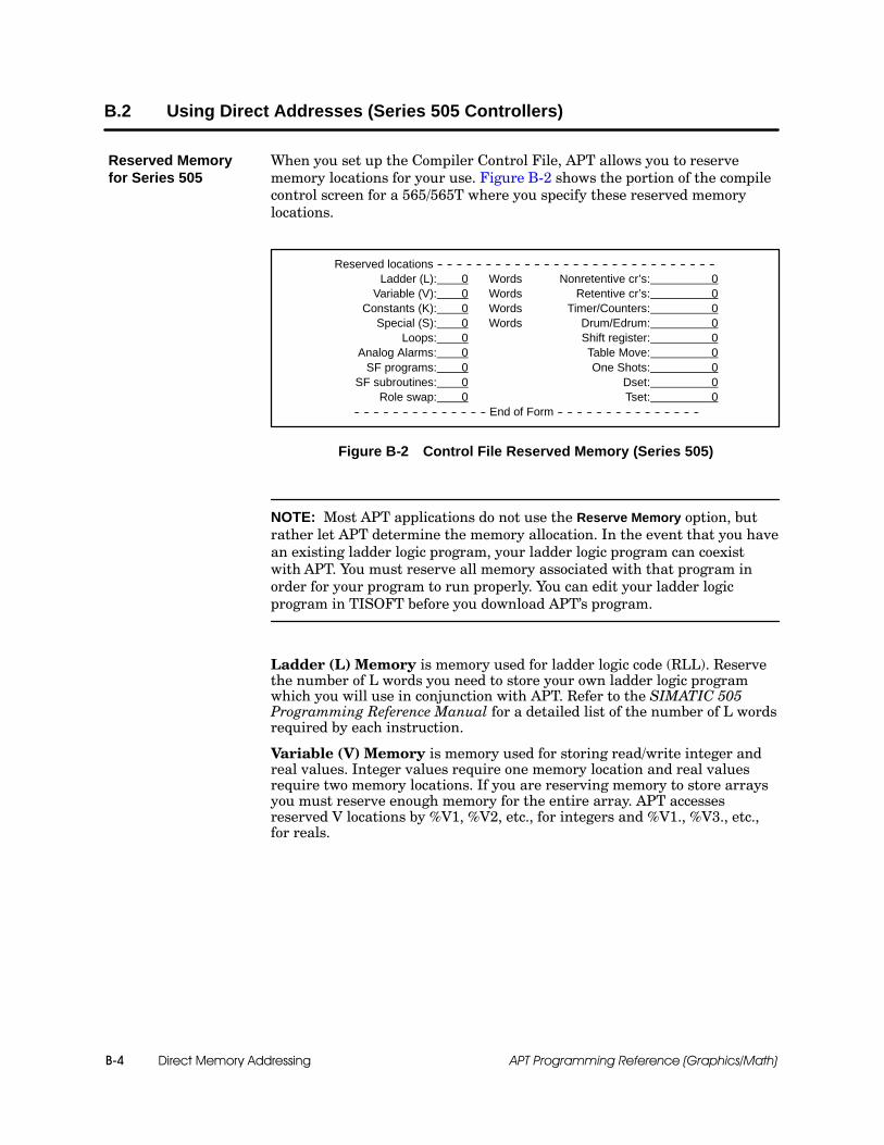
Direct Memory AddressingB-4 APT Programming Reference (Graphics/Math)
B.2 Using Direct Addresses (Series 505 Controllers)
When you set up the Compiler Control File, APT allows you to reservememory locations for your use. Figure B-2 shows the portion of the compilecontrol screen for a 565/565T where you specify these reserved memorylocations.
Reserved locations -- -- -- -- -- -- -- -- -- -- -- -- -- -- -- -- -- -- -- -- -- -- -- -- -- -- -- -- --Ladder (L): 0 Words Nonretentive cr’s: 0
Variable (V): 0 Words Retentive cr’s: 0Constants (K): 0 Words Timer/Counters: 0
Special (S): 0 Words Drum/Edrum: 0Loops: 0 Shift register: 0
Analog Alarms: 0 Table Move: 0SF programs: 0 One Shots: 0
SF subroutines: 0 Dset: 0Role swap: 0 Tset: 0
-- -- -- -- -- -- -- -- -- -- -- -- -- -- End of Form -- -- -- -- -- -- -- -- -- -- -- -- -- -- --
Figure B-2 Control File Reserved Memory (Series 505)
NOTE: Most APT applications do not use the Reserve Memory option, butrather let APT determine the memory allocation. In the event that you havean existing ladder logic program, your ladder logic program can coexistwith APT. You must reserve all memory associated with that program inorder for your program to run properly. You can edit your ladder logicprogram in TISOFT before you download APT’s program.
Ladder (L) Memory is memory used for ladder logic code (RLL). Reservethe number of L words you need to store your own ladder logic programwhich you will use in conjunction with APT. Refer to the SIMATIC 505Programming Reference Manual for a detailed list of the number of L wordsrequired by each instruction.
Variable (V) Memory is memory used for storing read/write integer andreal values. Integer values require one memory location and real valuesrequire two memory locations. If you are reserving memory to store arraysyou must reserve enough memory for the entire array. APT accessesreserved V locations by %V1, %V2, etc., for integers and %V1., %V3., etc.,for reals.
Reserved Memoryfor Series 505

Direct Memory Addressing B-5APT Programming Reference (Graphics/Math)
Constant (K) Memory is memory used for storing read only integer andreal values. Integer values require one memory location and real valuesrequire two memory locations. If you are reserving memory to store arraysyou must reserve enough memory for the entire array. APT accessesreserved K locations by %K1, %K2, etc., for integers and %K1., %K3., etc.,for reals.
Special (S) Memory is memory used for storing loops, analog alarms andspecial function programs. Enter the number of S-memory words you needto reserve. You can use TISOFT to see how much S-memory your loops,analog alarms, or special function programs require.
Loops enter the number of loops you want to reserve. In APT, access thesereserved loops on the CFB loop definition form by %loop1, %loop2, etc.
Analog Alarms enter the number of analog alarms you want to reserve. InAPT, access these reserved analog alarms on the CFB analog alarm form by%aalm1, %aalm2, etc.
SF Programs is memory used for Special Function programs (SFPGM).Enter the number of SF programs you want to reserve. They will be calledSFPGM1, SFPGM2, etc. and must be created and called by a ladder logicprogram in TISOFT.
SF Subroutines subroutines that are SFPGM only. Enter the number ofSF subroutines you want to reserve. They will be called SFSUB1, SFSUB2,etc. and must be created and called by a ladder logic program in TISOFT.
Role Swap The 565 controller has the redundant controller option wheretwo controllers are running and one controller is a hot back-up of the othercontroller. Enter the number of Force Role Swaps you need to reserve. Theywill be called FRS1, FRS2, etc. and the role swap will have to beprogrammed in ladder logic in TISOFT.
Non-retentive CRs is memory used to store internal digital information.Non-retentive CRs lose their value in the event of a power failure. Enter thenumber of non-retentive CRs you need to reserve. If you are using arrays,you must reserve enough memory for the whole array. APT accesses thesereserved CRs by %C1, %C2, etc. See the SIMATIC APT ProgrammingReference (Tables) Manual, Boolean Array Declaration.
NOTE: When you reserve retentive and non-retentive CRs, you are notreserving actual addresses; you are only reserving an amount of space. Forinstance, if you specify 780 non-retentive CRs, you get %C1--%C768 and%C1025--%C1036. If you specify 10 retentive CRs, you get %C769--%C778.

Direct Memory AddressingB-6 APT Programming Reference (Graphics/Math)
Using Direct Addresses (Series 505 Controllers) (continued)
Retentive CRs is memory used to store internal digital information.Retentive CRs keep their value in the event of a power failure. Enter thenumber of retentive CRs you need to reserve. If you are using arrays, youmust reserve enough memory for the whole array. APT accesses thesereserved CRs by %C769, %C770, etc. See the Boolean Array Declarationsection in the SIMATIC APT Programming Reference (Tables) Manual.
Timers/Counters is memory used for storing the current and preset valuesfor timers and counters. Enter the number of timers and counters you needto reserve. In APT, access these timers and counters on the timer andcounter declaration forms by entering %TC1, %TC2, etc.
Drum/Edrum is memory that stores the Drum Step preset and current andthe Drum Count preset and current. Enter the number of drums you need toreserve. Drums are not used by APT; they must be created and called by aladder logic program in TISOFT.
Shift Register is a memory type that consists of one byte per shift register.Enter the number of bytes you wish to reserve. The shift registers must becreated and called by a ladder logic program in TISOFT.
Table Move is a block of memory within the controller reserved for theoperation of table moves. Enter the number of words you would like toreserve to maintain the current count for each table move. The MWTT andMWFT will have to be created and called by a ladder logic program inTISOFT.
One Shots is a memory type that consists of one byte per configured oneshot instruction. Enter the number of bytes you would like to reserve tomonitor one shots. The one shots will have to be programmed in a ladderlogic program in TISOFT.
Dset Enter the number of date set box instructions you want to reserve.They must be programmed and called by a ladder logic program in TISOFT.
Tset Enter the number of time set box instructions you want to reserve.They must be programmed and called by a ladder logic program in TISOFT.
Direct Memory Addressing B-7APT Programming Reference (Graphics/Math)
Two other reserved locations exist for the 545, 555, and 575. They areReport by Exception and User Memory.
Report by Exception (RBE) (Only available for controller Release 3.0and higher and OSx/PCS Release 3.x and higher.) To use Report byException with PCS or OSx tag translate, memory must be allocated. Tocalculate the amount of memory needed, refer to the SIMATIC APTApplications Manual in the chapter on “APT and the OSx OperatorInterface.” The default allocation of 20K of memory is the minimumallocation. Any entry less than 20K results in a 20K allocation. If yourequire more than 20K, you must enter all of the memory required for RBE.
User Memory Externally developed subroutines written in C, PASCAL orassembly languages, can be used by APT, if you reserve user memory forthem. There are two ways to allocate user memory. Either reserve thenumber of U-memory words you need, or else enter the U-memory filename.If you are using a U-memory filename, APT determines the amount ofU-memory needed. Only use one method. The U-memory file contains theexternally-developed subroutines, and it must be located in theAPT\PROGRAM\<your program>\PRR subdirectory. See the SIMATIC 505Programming Reference Manual for more details about this type of memory.
Other ReservedLocations

Direct Memory AddressingB-8 APT Programming Reference (Graphics/Math)
Using Direct Addresses (Series 505 Controllers) (continued)
Table B-1 lists the direct addresses that are supported by APT forSeries 505 controllers.
Table B-1 Direct Addresses Supported by APT for Series 505 Controllers
Address Description Debug MAITT APT Objects MathLanguage
%AACK Analog alarm acknowledge Yes Yes Yes
%AADB Analog alarm deadband Yes Yes Yes
%AALM Analog alarm Yes
%ACFH Analog alarm C-flags high Yes Yes Yes
%ACFL Analog alarm C-flags low Yes Yes Yes
%AERR Analog alarm error Yes Yes Yes
%AHA Analog alarm high alarm Yes Yes Yes
%AHHA Analog alarm high-high alarm Yes Yes Yes
%ALA Analog alarm low alarm Yes Yes Yes
%ALLA Analog alarm low-low alarm Yes Yes Yes
%AODA Analog alarm orange deviation alarm Yes Yes Yes
%APET Analog alarm process execution time Yes Yes Yes
%APV Analog alarm process variable Yes Yes Yes
%APVH Analog alarm process variable high Yes Yes Yes
%APVL Analog alarm process variable low Yes Yes Yes
%ARCA Analog alarm rate-of-change alarm Yes Yes Yes
%ASP Analog alarm setpoint Yes Yes Yes
%ASPH Analog alarm setpoint high Yes Yes Yes
%ASPL Analog alarm setpoint low Yes Yes Yes
%ATS Analog alarm sample time Yes Yes Yes
%AVF Analog alarm V-flags Yes Yes Yes
%AYDA Analog alarm yellow deviation alarm Yes Yes Yes
%C Control relay Yes Yes Yes Yes
%DCP Drum current preset Yes Yes Yes
%DSC Drum step current Yes Yes Yes
%DSP Drum step preset Yes Yes Yes
%G Global memory * Yes Yes Yes Yes
%Gx Global application memory * Yes Yes Yes Yes
%K Constant * Yes Yes Yes Yes
%LACK Loop acknowledge Yes Yes Yes
%LADB Loop deadband Yes Yes Yes
%LCFH Loop C-flags high Yes Yes Yes
%LCFL Loop C-flags low Yes Yes Yes
%LERR Loop error Yes Yes Yes
%LHA Loop high alarm Yes Yes Yes

Direct Memory Addressing B-9APT Programming Reference (Graphics/Math)
Table B-1 Direct Addresses Supported by APT for Series 505 Controllers (continued)
Address Description Debug MAITT APT Objects MathLanguage
%LHHA Loop high-high alarm Yes Yes Yes
%LKC Loop proportional gain Yes Yes Yes
%LKD Loop derivative gain limiting coefficient Yes Yes Yes
%LLA Loop low alarm Yes Yes Yes
%LLLA Loop low-low alarm Yes Yes Yes
%LMN Loop output Yes Yes Yes
%LMX Loop bias Yes Yes Yes
%LODA Loop orange deviation alarm Yes Yes Yes
%LOOP Loop Yes
%LPET Loop process execution time Yes Yes Yes
%LPV Loop process variable Yes Yes Yes
%LPVH Loop process variable high Yes Yes Yes
%LPVL Loop process variable low Yes Yes Yes
%LRCA Loop rate-of-change alarm Yes Yes Yes
%LRSF Loop ramp soak flags Yes Yes Yes
%LSP Loop setpoint Yes Yes Yes
%LSPH Loop setpoint high Yes Yes Yes
%LSPL Loop setpoint low Yes Yes Yes
%LTD Loop derivative time Yes Yes Yes
%LTI Loop integral time Yes Yes Yes
%LTS Loop sample time Yes Yes Yes
%LVF Loop V-flags Yes Yes Yes
%LYDA Loop yellow deviation alarms Yes Yes Yes
%PPET SFSUB process execution time Yes Yes Yes
%SPET SFPGM process execution time Yes Yes Yes
%STW Controller status word * Yes Yes Yes Yes
%TCC Timer/counter current Yes Yes Yes
%TCP Timer/counter preset Yes Yes Yes
%TPET Task process execution time Yes Yes Yes
%VMM,%VMS VME memory * Yes Yes Yes Yes
%V Variable memory * Yes Yes Yes Yes
%WX Word input * Yes Yes Yes
%WY Word output * Yes Yes Yes
%X Discrete input * Yes Yes Yes
%Y Discrete output * Yes Yes Yes
* See the following section, “Direct Addressing Guidelines for Series 505 Controller.”
Direct Memory AddressingB-10 APT Programming Reference (Graphics/Math)
Using Direct Addresses (Series 505 Controllers) (continued)
For Series 505 controllers, integer values require one memory location. Realvalues require two memory locations, and are referenced with a period ( . )following the address, except in the Declaration Table. For example, %V100.accesses the real value stored in memory location V100 and V101.
For Series 505 S-memory, real values for loops and analog alarms onlyrequire one memory location; however, they still have to be referenced witha period ( . ). Refer to Chapter 2, Table 2-5, for loop memory, and Table 2-13for analog alarm memory.
The first available direct memory address for a Series 505 controller is 1,not 0. Do not use a direct memory address to access Series 505 controlmemory addresses X0, Y0, V0, K0, STW0, WX0, or WY0, e.g., %X0, %Y0,etc. These addresses do not exist, and an “illegal direct address” error occurswhen the program is compiled.
The following types of memory are available only on the 575 controller:G, VMM, and VMS.
There are two types of Series 505 VME memory: VMS, which corresponds toVME address (16-bit address), and VMM, which corresponds to VMEaddress (24-bit address). Both of these memory types use byte-orientedaddressing. For example, writing an integer (V-memory) to %VMM0F000writes to both %VMM0F000 and %VMM0F001. Consequently, you cannotreference odd-numbered VMM- or VMS-memory addresses.
Both VMS and VMM memory must be referenced with hex addresses. Also,the address must begin with a digit. Since hex addresses can sometimesbegin with a letter (A through F), you may have to insert a “0” (zero) in frontof the address.
575 G-memory types can be referenced as %G1, or as %GA1, where A is theapplication ID (A through Z are valid application IDs). If you do not specifyan application, the default is the current application. Initial values will onlybe downloaded for the declarations defined without the application ID.
Direct AddressingGuidelines forSeries 505Controllers

Direct Memory Addressing B-11APT Programming Reference (Graphics/Math)
B.3 Using Direct Addresses (S5 Controllers)
When you fill out the Compiler Control File, APT allows you to reservememory locations for your use. Figure B-3 shows the portion of the compilercontrol screen for an S5 928B or 948U/948R CPU where you specify thesereserved memory locations.
Reserved locations -- -- -- -- -- -- -- -- -- -- -- -- -- -- -- -- -- -- -- -- -- -- -- -- -- -- -- -- --Data Blocks (DB):
Ext. Data Blocks (DX):Function Blocks (FB):
Ext. Function Blocks (FX):Program Blocks (PB):
Sequence Blocks (SB):Flag Bytes:
S-Flag Bytes:Timers:
Counters::
Figure B-3 Control File Reserved Memory (S5)
Enter the actual numbers that you want to reserve. For instance, if youplace a 10 after Data Blocks on the form, then you reserve DB10. Separatenumbers by commas, and show a range of numbers by placing a colon ( : )between the starting number and the ending number. For example, if youenter these numbers after Function Blocks: 40, 41, 50:59, 255, then you arereserving FB40, FB41, FB50 through FB59, and FB255. Because you havereserved these function blocks, APT will not use them, and you can programthem in STL and download them to the controller using STEP 5.
NOTE: If your function blocks, program blocks, or sequence blocks use anydata blocks, flag words, etc., you must reserve these, too.
Data Blocks (DB) Enter the data blocks that your S5 program uses.Valid entries are 5--255 for the 948U/R CPUs, and 3--255 for the 928B. Thecontroller uses DB0--DB2 for a 928B CPU, or DB0--DB4 for the 948U/R.When you reserve a data block, you get the entire data block. APT assumesthe length of the DB is 256 words.
Extended Data Blocks (DX) Enter the extended data blocks that yourS5 program uses. Valid entries are 2--255. When you reserve an extendeddata block, you get the entire data block. APT assumes the length of the DXis 256 words.
Reserved Memoryfor S5 Controllers

Direct Memory AddressingB-12 APT Programming Reference (Graphics/Math)
Using Direct Addresses (S5 Controllers) (continued)
Function Blocks (FB) Enter the function blocks that you want toreserve. Valid entries are 0--255. These function blocks can be either onesthat you purchased or ones you have written. You must download thefunction blocks to the controller after you download your APT program. Donot put the controller in RUN mode until you have downloaded all reservedfunction blocks to the controller. Every time you clear the controller youmust download the function blocks again. If your function blocks use anydata or flags, reserve the appropriate memory. Maximum FB lengthpermitted by APT is 4K.
Ext. Function Blocks (FX) Enter the extended function blocks that youwant to reserve. Valid entries are 0--255. You must download the extendedfunction blocks to the controller after you download APT. Every time youclear the controller you must download the extended function blocks again.Maximum FX length permitted by APT is 4K.
Program Blocks (PB) Enter the program blocks that you want toreserve. Valid entries are 0--255. Maximum PB length permitted by APT is4K.
Sequence Blocks (SB) Enter the sequence blocks that you want toreserve. Valid entries are 0--255. Maximum SB length permitted by APT is4K.
Flag Bytes Enter the flag bytes that you want to reserve. Valid entriesare 2--199. APT uses FW0 (FY0 and FY1) as the H-flag word for redundantcontrol. You cannot reserve flag bytes 200--255 because APT uses them as ascratch flag area. Your function block, program block, or sequence block canshare the scratch flag area with APT, but you cannot reserve these bytes.
S-Flag Bytes Enter the extended flag bytes (S-flags) that you want toreserve. Valid entries are 0--1023 for a 928B CPU, or 0--4096 for the 948U/RCPU.
NOTE: When you reserve a flag byte or an extended flag byte, you get alleight bits of the flag. If you are using flags for integers, remember to reservetwo flags for each integer. If you are using real numbers, remember toreserve four flags for each real number.
Timers Enter the number of S5 timers that you want to reserve. Validentries are 0--255, which reserve timers TMR0 to TMR255.
Counters Enter the number of S5 counters that you want to reserve.Valid entries are 0--255, which reserve counters CTR0 to CTR255.
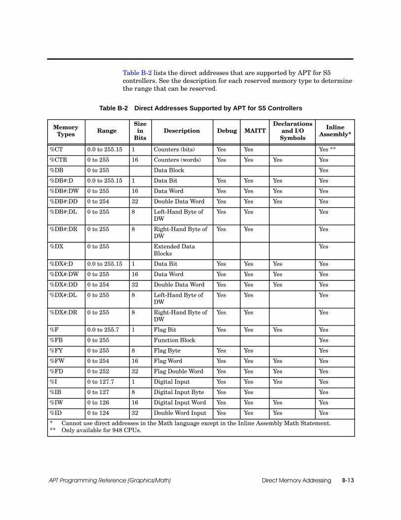
Direct Memory Addressing B-13APT Programming Reference (Graphics/Math)
Table B-2 lists the direct addresses that are supported by APT for S5controllers. See the description for each reserved memory type to determinethe range that can be reserved.
Table B-2 Direct Addresses Supported by APT for S5 Controllers
MemoryTypes Range
SizeinBits
Description Debug MAITTDeclarations
and I/OSymbols
InlineAssembly*
%CT 0.0 to 255.15 1 Counters (bits) Yes Yes Yes **
%CTR 0 to 255 16 Counters (words) Yes Yes Yes Yes
%DB 0 to 255 Data Block Yes
%DB#:D 0.0 to 255.15 1 Data Bit Yes Yes Yes Yes
%DB#:DW 0 to 255 16 Data Word Yes Yes Yes Yes
%DB#:DD 0 to 254 32 Double Data Word Yes Yes Yes Yes
%DB#:DL 0 to 255 8 Left-Hand Byte ofDW
Yes Yes Yes
%DB#:DR 0 to 255 8 Right-Hand Byte ofDW
Yes Yes Yes
%DX 0 to 255 Extended DataBlocks
Yes
%DX#:D 0.0 to 255.15 1 Data Bit Yes Yes Yes Yes
%DX#:DW 0 to 255 16 Data Word Yes Yes Yes Yes
%DX#:DD 0 to 254 32 Double Data Word Yes Yes Yes Yes
%DX#:DL 0 to 255 8 Left-Hand Byte ofDW
Yes Yes Yes
%DX#:DR 0 to 255 8 Right-Hand Byte ofDW
Yes Yes Yes
%F 0.0 to 255.7 1 Flag Bit Yes Yes Yes Yes
%FB 0 to 255 Function Block Yes
%FY 0 to 255 8 Flag Byte Yes Yes Yes
%FW 0 to 254 16 Flag Word Yes Yes Yes Yes
%FD 0 to 252 32 Flag Double Word Yes Yes Yes Yes
%I 0 to 127.7 1 Digital Input Yes Yes Yes Yes
%IB 0 to 127 8 Digital Input Byte Yes Yes Yes
%IW 0 to 126 16 Digital Input Word Yes Yes Yes Yes
%ID 0 to 124 32 Double Word Input Yes Yes Yes Yes
* Cannot use direct addresses in the Math language except in the Inline Assembly Math Statement.g g p y** Only available for 948 CPUs.

Direct Memory AddressingB-14 APT Programming Reference (Graphics/Math)
Using Direct Addresses (S5 Controllers) (continued)
Table B-2 Direct Addresses Supported by APT for S5 Controllers (continued)
MemoryTypes Range
SizeinBits
Description Debug MAITTDeclarations
and I/OSymbols
InlineAssembly*
%KB 0 to 255 8 Constant (1 byte) Yes
%KC 0 to 999 16 Constant (count) Yes
%KF --32768 to32767
16 Constant(fixed point)
Yes
%KG --1.7E38 to1.7E38
32 Constant(floating point)
Yes
%KH 0 to FFFF 16 Constant(hexadecimal)
Yes
%KM 0s and 1s only 16 Constant(2 byte-bit pattern)
Yes
%KS ASCII Char-acters
16 Constant (2 charac-ters)
Yes
%KT 0.0 to 999.3 16 Constant (time) Yes
%KY 0 to 255 16 Constant (2 bytes) Yes
%OW 0 to 254 16 ExtendedPeripheral Word
Yes Yes Yes Yes
%OY 0 to 255 8 ExtendedPeripheral Byte
Yes Yes Yes
%PB 0 to 255 Program Blocks Yes
%PW 0 to 254 16 Peripheral Word Yes Yes Yes Yes
%PY 0 to 255 8 Peripheral Byte Yes Yes Yes
%Q 0.0 to 127.7 1 Digital Output Yes Yes Yes Yes
%QB 0 to 127 8 Digital Output Byte Yes Yes Yes
%QW 0 to 126 16 Digital OutputWord
Yes Yes Yes Yes
%QD 0 to 124 32 Double OutputWord
Yes Yes Yes Yes
%RI 0.0 to 255.15 1 Interface Data Area(bits)
Yes Yes Yes **
%RIW 0 to 255 16 Interface Data Area(words)
Yes Yes Yes
* Cannot use direct addresses in the Math Language except in the Inline Assembly Math Statement.g g p y** Only available for 948 CPUs.

Direct Memory Addressing B-15APT Programming Reference (Graphics/Math)
Table B-2 Direct Addresses Supported by APT for S5 Controllers (continued)
MemoryTypes Range
SizeinBits
Description Debug MAITTDeclarations
and I/OSymbols
InlineAssembly*
%RJ 0.0 to 255.15 1 Extended InterfaceData Area (bits) Yes Yes Yes **
%RJW 0 to 255 16 Extended InterfaceData Area (words) Yes Yes Yes
%RS 0.0 to 255.15 1 System Data Area(bits) Yes Yes Yes **
%RSW 0 to 255 16 System Data Area(words) Yes Yes Yes
%RT 0.0 to 255.15 1 Extended SystemData Area (bits) Yes Yes Yes **
%RTW 0 to 255 16 Extended SystemData Area (words) Yes Yes Yes
%S
0.0 to 1023.7(928B)0.0 to 4095.7(948U/R)
1 Extended Flag Bit Yes Yes Yes Yes
%SB 0 to 255 Sequence Blocks Yes
%SY
0.0 to 1023(928B)0.0 to 4095(948U/R)
8 Extended Flag Byte Yes Yes Yes
%SW
0 to 1022(928B)0 to 4094(948U/R)
16 Extended Flag Word Yes Yes Yes Yes
%SD
0 to 1020(928B)0 to 4092(948U/R)
32 Extended DoubleFlag Word Yes Yes Yes Yes
%TM 0.0 to 255.15 1 Timers (bits) Yes Yes Yes **
%TMR 0 to 255 16 Timers (words) Yes Yes Yes Yes
* Cannot use direct addresses in the Math language except in the Inline Assembly Math Statement.Cannot use direct addresses in the Math language except in the Inline Assembly Math Statement.** Only available for 948 CPUs.

Direct Memory AddressingB-16 APT Programming Reference (Graphics/Math)
Using Direct Addresses (S5 Controllers) (continued)
For S5 controllers, integer values require two flag-byte memory locations orone DB/DX data-word memory location. Real values require four flag-bytememory locations or two DB/DX data-word memory locations. Real numbersare referenced with a period ( . ) following the address, except in theDeclaration Table. For example, %FD100. accesses the real value stored inmemory locations FY100, FY101, FY102, and FY103.
Use the APT Declaration Table to assign symbolic names to reserved flagand DB/DX memory so that you can reference flag and DB/DX memory inAPT by their symbolic names instead of their direct addresses.
Use an inline assembly math statement to call OBs greater than OB39 andreserved FBs, FXs, PBs, or SBs. Refer to Appendix C of this manual, “InlineAssembly Code for S5,” for information on the inline assembly mathstatement.
You cannot reserve the scratch flag area (F200 to F255), but you can use itin your own FBs, FXs, PBs, or SBs when you call them with the inlineassembly math statement. APT uses this area on an ongoing basis andcontinually overwrites its contents. If your FB, FX, PB, or SB uses scratchflags, they are local to the block, and they are overwritten after the FB, PB,or SB executes.
If you want to use external FBs, FXs, PBs, or SBs, you must reserve themin the Compiler Control File. Download your APT program before youdownload your FBs, FXs, PBs, or SBs to the controller. Any time you clearthe controller memory, you must download the blocks again. If you put yourcontroller in RUN mode and the blocks have not been downloaded, you getan error and the controller goes to STOP mode. To avoid having tore-download your blocks when you use a Force Compile, do not selectthe Clear Memory option; this way your blocks remain in the controllermemory, and you can set the controller to RUN mode.
When you reserve flag or DB/DX memory, you must download them into thecontroller before you use them. If you perform a COLDSTART afterwards,the flag words are set to zero and must be downloaded again; however, theDB/DX memory retains the same value as before the COLDSTART. If youperform an overall reset, which clears all memory, you must download bothflag and DB/DX memory again.
Direct AddressingGuidelines for S5Controllers
Inline Assembly Code for S5 C-1APT Programming Reference (Graphics/Math)
Appendix C
Inline Assembly Code for S5
C.1 The IN_ASM Statement C-2. . . . . . . . . . . . . . . . . . . . . . . . . . . . . . . . . . . . . . . . . . . . . . . . . . . . . . . . .Overview C-2. . . . . . . . . . . . . . . . . . . . . . . . . . . . . . . . . . . . . . . . . . . . . . . . . . . . . . . . . . . . . . . . . . . . . . .Availability C-2. . . . . . . . . . . . . . . . . . . . . . . . . . . . . . . . . . . . . . . . . . . . . . . . . . . . . . . . . . . . . . . . . . . . . .Formatting Inline Assembly Math Statements C-4. . . . . . . . . . . . . . . . . . . . . . . . . . . . . . . . . . . . . . . .
C.2 Parameters Available for IN_ASM Statements C-5. . . . . . . . . . . . . . . . . . . . . . . . . . . . . . . . . . . . .Overview C-5. . . . . . . . . . . . . . . . . . . . . . . . . . . . . . . . . . . . . . . . . . . . . . . . . . . . . . . . . . . . . . . . . . . . . . .Direct Addresses C-5. . . . . . . . . . . . . . . . . . . . . . . . . . . . . . . . . . . . . . . . . . . . . . . . . . . . . . . . . . . . . . . .Flags and Other Bits C-5. . . . . . . . . . . . . . . . . . . . . . . . . . . . . . . . . . . . . . . . . . . . . . . . . . . . . . . . . . . . .Words and Double Words C-5. . . . . . . . . . . . . . . . . . . . . . . . . . . . . . . . . . . . . . . . . . . . . . . . . . . . . . . .APT Symbolic Names C-6. . . . . . . . . . . . . . . . . . . . . . . . . . . . . . . . . . . . . . . . . . . . . . . . . . . . . . . . . . . .Constants C-8. . . . . . . . . . . . . . . . . . . . . . . . . . . . . . . . . . . . . . . . . . . . . . . . . . . . . . . . . . . . . . . . . . . . . .
C.3 How to Incorporate Your Block C-10. . . . . . . . . . . . . . . . . . . . . . . . . . . . . . . . . . . . . . . . . . . . . . . . . .Overview C-10. . . . . . . . . . . . . . . . . . . . . . . . . . . . . . . . . . . . . . . . . . . . . . . . . . . . . . . . . . . . . . . . . . . . . . .Incorporating Blocks with No Parameters C-11. . . . . . . . . . . . . . . . . . . . . . . . . . . . . . . . . . . . . . . . . . .Example C-11. . . . . . . . . . . . . . . . . . . . . . . . . . . . . . . . . . . . . . . . . . . . . . . . . . . . . . . . . . . . . . . . . . . . . . .Loading a Parameter List C-12. . . . . . . . . . . . . . . . . . . . . . . . . . . . . . . . . . . . . . . . . . . . . . . . . . . . . . . . .Example C-15. . . . . . . . . . . . . . . . . . . . . . . . . . . . . . . . . . . . . . . . . . . . . . . . . . . . . . . . . . . . . . . . . . . . . . .Using the Accumulators C-16. . . . . . . . . . . . . . . . . . . . . . . . . . . . . . . . . . . . . . . . . . . . . . . . . . . . . . . . . .Loading the Accumulators C-17. . . . . . . . . . . . . . . . . . . . . . . . . . . . . . . . . . . . . . . . . . . . . . . . . . . . . . . .Example C-18. . . . . . . . . . . . . . . . . . . . . . . . . . . . . . . . . . . . . . . . . . . . . . . . . . . . . . . . . . . . . . . . . . . . . . .Opening a Data Block C-19. . . . . . . . . . . . . . . . . . . . . . . . . . . . . . . . . . . . . . . . . . . . . . . . . . . . . . . . . . . .
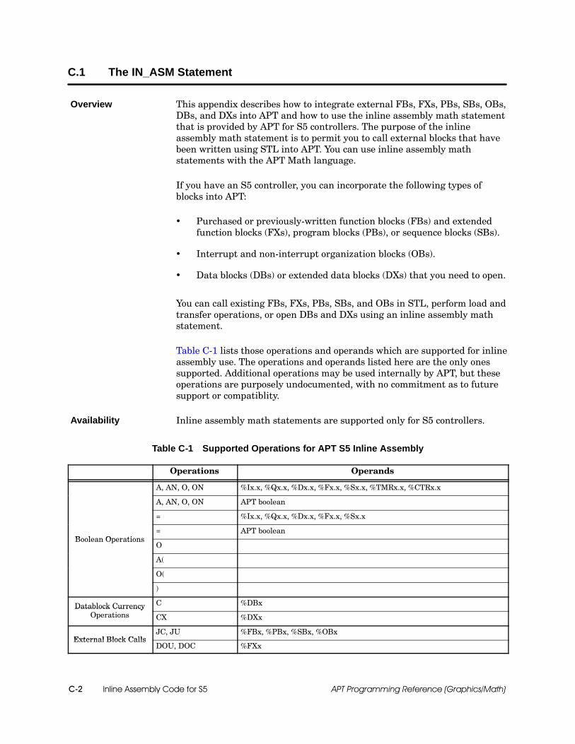
Inline Assembly Code for S5C-2 APT Programming Reference (Graphics/Math)
C.1 The IN_ASM Statement
This appendix describes how to integrate external FBs, FXs, PBs, SBs, OBs,DBs, and DXs into APT and how to use the inline assembly math statementthat is provided by APT for S5 controllers. The purpose of the inlineassembly math statement is to permit you to call external blocks that havebeen written using STL into APT. You can use inline assembly mathstatements with the APT Math language.
If you have an S5 controller, you can incorporate the following types ofblocks into APT:
Purchased or previously-written function blocks (FBs) and extendedfunction blocks (FXs), program blocks (PBs), or sequence blocks (SBs).
Interrupt and non-interrupt organization blocks (OBs).
Data blocks (DBs) or extended data blocks (DXs) that you need to open.
You can call existing FBs, FXs, PBs, SBs, and OBs in STL, perform load andtransfer operations, or open DBs and DXs using an inline assembly mathstatement.
Table C-1 lists those operations and operands which are supported for inlineassembly use. The operations and operands listed here are the only onessupported. Additional operations may be used internally by APT, but theseoperations are purposely undocumented, with no commitment as to futuresupport or compatiblity.
Inline assembly math statements are supported only for S5 controllers.
Table C-1 Supported Operations for APT S5 Inline Assembly
Operations Operands
A, AN, O, ON %Ix.x, %Qx.x, %Dx.x, %Fx.x, %Sx.x, %TMRx.x, %CTRx.x
A, AN, O, ON APT boolean
= %Ix.x, %Qx.x, %Dx.x, %Fx.x, %Sx.x
Boolean Operations= APT boolean
Boolean OperationsO
A(
O(
)
Datablock Currency C %DBxDatablock CurrencyOperations CX %DXx
External Block CallsJC, JU %FBx, %PBx, %SBx, %OBx
External Block CallsDOU, DOC %FXx
Overview
Availability
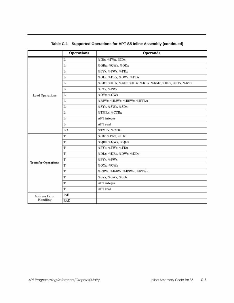
Inline Assembly Code for S5 C-3APT Programming Reference (Graphics/Math)
Table C-1 Supported Operations for APT S5 Inline Assembly (continued)
Operations Operands
L %IBx, %IWx, %IDx
L %QBx, %QWx, %QDx
L %FYx, %FWx, %FDx
L %DLx, %DRx, %DWx, %DDx
L %KBx, %KCx, %KFx, %KGx, %KHx, %KMx, %KSx, %KTx, %KYx
L %PYx, %PWx
Load Operations L %OYx, %OWxp
L %RIWx, %RJWx, %RSWx, %RTWx
L %SYx, %SWx, %SDx
L %TMRx, %CTRx
L APT integer
L APT real
LC %TMRx, %CTRx
T %IBx, %IWx, %IDx
T %QBx, %QWx, %QDx
T %FYx, %FWx, %FDx
T %DLx, %DRx, %DWx, %DDx
Transfer OperationsT %PYx, %PWx
Transfer OperationsT %OYx, %OWx
T %RIWx, %RJWx, %RSWx, %RTWx
T %SYx, %SWx, %SDx
T APT integer
T APT real
Address Error IAEAddress ErrorHandling RAE
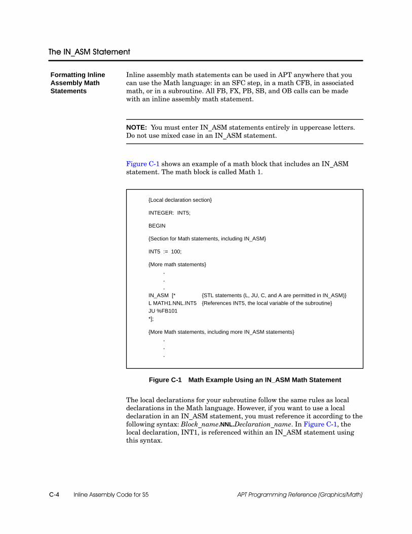
Inline Assembly Code for S5C-4 APT Programming Reference (Graphics/Math)
The IN_ASM Statement
Inline assembly math statements can be used in APT anywhere that youcan use the Math language: in an SFC step, in a math CFB, in associatedmath, or in a subroutine. All FB, FX, PB, SB, and OB calls can be madewith an inline assembly math statement.
NOTE: You must enter IN_ASM statements entirely in uppercase letters.Do not use mixed case in an IN_ASM statement.
Figure C-1 shows an example of a math block that includes an IN_ASMstatement. The math block is called Math 1.
{Local declaration section}
INTEGER: INT5;
BEGIN
{Section for Math statements, including IN_ASM}
INT5 := 100;
{More math statements}...
IN_ASM [* {STL statements (L, JU, C, and A are permitted in IN_ASM)}L MATH1.NNL.INT5 {References INT5, the local variable of the subroutine}JU %FB101*];
{More Math statements, including more IN_ASM statements}...
Figure C-1 Math Example Using an IN_ASM Math Statement
The local declarations for your subroutine follow the same rules as localdeclarations in the Math language. However, if you want to use a localdeclaration in an IN_ASM statement, you must reference it according to thefollowing syntax: Block_name.NNL.Declaration_name. In Figure C-1, thelocal declaration, INT1, is referenced within an IN_ASM statement usingthis syntax.
Formatting InlineAssembly MathStatements

Inline Assembly Code for S5 C-5APT Programming Reference (Graphics/Math)
C.2 Parameters Available for IN_ASM Statements
When you call an FB, FX, PB, SB, or OB that has parameters, theparameters are either loaded into the accumulators or, for FBs and FXsonly, loaded into a parameter list. This section discusses the different typesof parameters that you can use in an inline assembly math statement.
You can use direct addresses as parameters in an inline assembly mathstatement. Refer to Appendix B for all the direct addresses allowed. If youuse a direct address, you must precede it with the percent sign ( % ). Do notenter a space after the % sign. All direct addresses supported for S5controllers are permitted in inline assembly math statements.
L %FW10 {loads a direct address}
To enter an S5 bit as a parameter, you must use the AND command. Forexample, to enter the S5 flag F1.1 as a parameter, use the following syntax:
A %F1.1
To incorporate the input bit I1.0 as a parameter, use the following syntax:
A %I1.0
To enter an S5 word or double word as a parameter, you must use the LOADcommand. For example, to enter the analog input PW128 as a parameter,use the following syntax:
L %PW128
To incorporate the input double word ID120 as a parameter, use thefollowing syntax:
L %ID120
Overview
Direct Addresses
Flags and OtherBits
Words andDouble Words

Inline Assembly Code for S5C-6 APT Programming Reference (Graphics/Math)
Parameters Available for IN_ASM Statements (continued)
You can use APT symbolic names as parameters in an inline assembly mathstatement. How you handle the parameter depends on whether you aresending it to the accumulators (for an FB, FX, PB, SB, or OB) or to aparameter list (FB, FX only).
NOTE: When you refer to APT symbolic names in any inline assembly mathstatement, regardless of where you are sending the parameter, write thesymbolic name entirely in uppercase letters. The Table editors for APT useuppercase. If you refer to an APT symbolic name in mixed case when youmake inline assembly math statements, the assembler cannot match it tothe correct declaration.
If you are using an APT symbolic name as a parameter that is sent to anaccumulator, follow these steps.
1. Use the Declaration Table, I/O Table, Recipe Table, or Device Table todeclare the APT symbolic name(s). You can use automatic addressing.
2. Issue a load statement according to the following syntax.
L THETA {loads the symbolic name Theta}{notice that the symbolic name is uppercased}
NOTE: When you use the symbolic name, the call to the DB/DX occurswhen loading parameters to the accumulators, but not when loadingparameters in a parameter list.
APT SymbolicNames
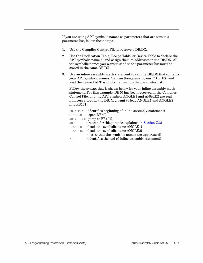
Inline Assembly Code for S5 C-7APT Programming Reference (Graphics/Math)
If you are using APT symbolic names as parameters that are sent to aparameter list, follow these steps.
1. Use the Compiler Control File to reserve a DB/DX.
2. Use the Declaration Table, Recipe Table, or Device Table to declare theAPT symbolic name(s) and assign them to addresses in the DB/DX. Allthe symbolic names you want to send to the parameter list must bestored in the same DB/DX.
3. Use an inline assembly math statement to call the DB/DX that containsyour APT symbolic names. You can then jump to your FB or FX, andload the desired APT symbolic names into the parameter list.
Follow the syntax that is shown below for your inline assembly mathstatement. For this example, DB50 has been reserved in the CompilerControl File, and the APT symbols ANGLE1 and ANGLE2 are realnumbers stored in the DB. You want to load ANGLE1 and ANGLE2into FB101.
IN_ASM[* {identifies beginning of inline assembly statement}C %DB50 {open DB50}JU %FB101 {jump to FB101}JU 3 {reason for this jump is explained in Section C.3}L ANGLE1 {loads the symbolic name ANGLE1}L ANGLE2 {loads the symbolic name ANGLE2}
{notice that the symbolic names are uppercased}*]; {identifies the end of inline assembly statement}
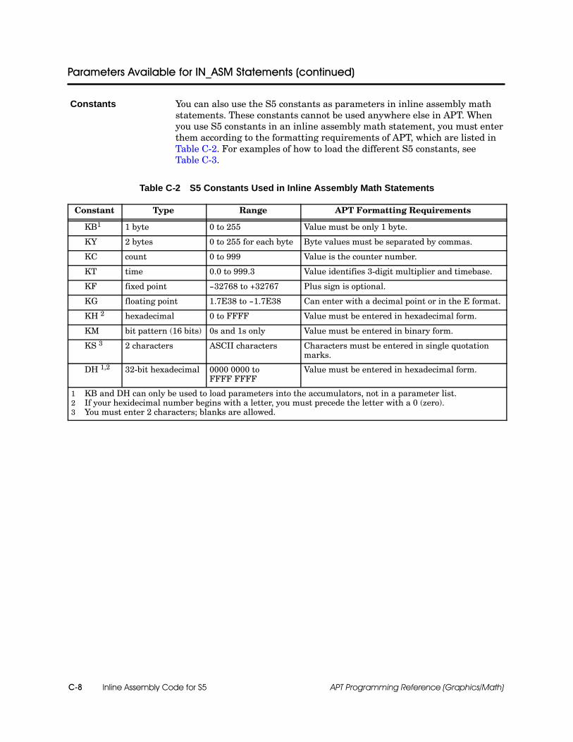
Inline Assembly Code for S5C-8 APT Programming Reference (Graphics/Math)
Parameters Available for IN_ASM Statements (continued)
You can also use the S5 constants as parameters in inline assembly mathstatements. These constants cannot be used anywhere else in APT. Whenyou use S5 constants in an inline assembly math statement, you must enterthem according to the formatting requirements of APT, which are listed inTable C-2. For examples of how to load the different S5 constants, seeTable C-3.
Table C-2 S5 Constants Used in Inline Assembly Math Statements
Constant Type Range APT Formatting Requirements
KB1 1 byte 0 to 255 Value must be only 1 byte.
KY 2 bytes 0 to 255 for each byte Byte values must be separated by commas.
KC count 0 to 999 Value is the counter number.
KT time 0.0 to 999.3 Value identifies 3-digit multiplier and timebase.
KF fixed point --32768 to +32767 Plus sign is optional.
KG floating point 1.7E38 to --1.7E38 Can enter with a decimal point or in the E format.
KH 2 hexadecimal 0 to FFFF Value must be entered in hexadecimal form.
KM bit pattern (16 bits) 0s and 1s only Value must be entered in binary form.
KS 3 2 characters ASCII characters Characters must be entered in single quotationmarks.
DH 1,2 32-bit hexadecimal 0000 0000 toFFFF FFFF
Value must be entered in hexadecimal form.
1 KB and DH can only be used to load parameters into the accumulators, not in a parameter list.2 If your hexidecimal number begins with a letter, you must precede the letter with a 0 (zero).3 You must enter 2 characters; blanks are allowed.
Constants
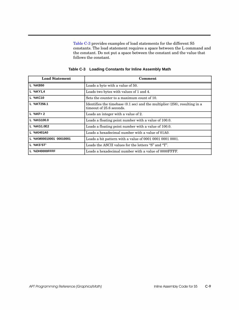
Inline Assembly Code for S5 C-9APT Programming Reference (Graphics/Math)
Table C-3 provides examples of load statements for the different S5constants. The load statement requires a space between the L command andthe constant. Do not put a space between the constant and the value thatfollows the constant.
Table C-3 Loading Constants for Inline Assembly Math
Load Statement Comment
L %KB50 Loads a byte with a value of 50.
L %KY1,4 Loads two bytes with values of 1 and 4.
L %KC10 Sets the counter to a maximum count of 10.
L %KT256.1 Identifies the timebase (0.1 sec) and the multiplier (256), resulting in atimeout of 25.6 seconds.
L %KF+ 2 Loads an integer with a value of 2.
L %KG100.0 Loads a floating point number with a value of 100.0.
L %KG1.0E2 Loads a floating point number with a value of 100.0.
L %KH01A0 Loads a hexadecimal number with a value of 01A0.
L %KM00010001 00010001 Loads a bit pattern with a value of 0001 0001 0001 0001.
L %KS’ST’ Loads the ASCII values for the letters “S” and “T”.
L %DH0000FFFF Loads a hexadecimal number with a value of 0000FFFF.
Inline Assembly Code for S5C-10 APT Programming Reference (Graphics/Math)
C.3 How to Incorporate Your Block
To incorporate an FB, FX, PB, SB, DB, or DX into APT, you must firstreserve the block in the Compiler Control File. For information about how toreserve blocks in the Compiler Control File, see the appendix on “DirectMemory Addressing” in this manual. You do not have to reserve OBs in theCompiler Control File, because OBs are resident in the S5 controller.
You can call external FBs, FXs, PBs, OBs, SBs, DBs, and DXs in an inlineassembly math statement from any one of these four locations: from withina math CFB, from associated math, from an SFC step with Math language,or from a subroutine. For information about how to edit a math CFB, seeChapter 8 of this manual. To learn about the Math language, seeChapter 10 of this manual. To edit a subroutine, see Chapter 10, “UserSubroutines,” in the SIMATIC APT Programming Reference (Tables)Manual.
You must download the external FBs, FXs, PBs, SBs, DBs, and DXs to thecontroller using STEP 5. The inline assembly math statements aredownloaded with APT. When you download your program to the controllerinitially, be sure to download APT before you download the FBs, FXs, PBs,SBs, DBs, and DXs. If you clear the memory in the controller later for anyreason, you must re-download all external FBs, FXs, PBs, SBs, DBs, andDXs.
Only selected OBs can be executed using the inline assembly mathstatement. If you have a 928B or 948U CPU, you can execute OB40--OB255.If you have a 948R CPU, you can execute OB121--OB255; OB40--OB120 areused for redundancy.
If you want to execute OB1--OB39, you need to use an APT system-activatedsubroutine, described in the “User Subroutines” chapter of the SIMATICAPT Programming Reference (Tables) Manual.
NOTE: You cannot modify the code in OBs using STEP 5. If you try to editOB1--OB39 using STEP 5, your modifications are overwritten by APT.
Overview

Inline Assembly Code for S5 C-11APT Programming Reference (Graphics/Math)
Many FBs, FXs, PBs, SBs, and OBs do not pass parameters through theaccumulators or in a parameter list. If you want to incorporate an FB, FX,PB, or SB without parameters into APT, you must first reserve the block inthe Compiler Control File. You can then edit your math CFB, SFC step,associated math, or subroutine.
Use the following format to create inline assembly math statements:
1. Enter the inline assembly identifier that indicates the beginning of thestatement.
IN_ASM[*
2. Enter the jump (that is, the call) to the FB, FX, PB, SB, or OB.
JU %FBxJU %FXxJU %PBxJU %SBxJU %OBx
where x is the number that identifies the FB, FX, PB, SB, or OB.
3. Enter the inline assembly identifier that indicates the end of thestatement.
*];
An inline assembly statement is a Math statement and must end in asemicolon.
The following example shows an inline assembly math statement thatincorporates a function block, FB101, into APT. Assume FB101 is auser-written subroutine that identifies the end of a telegram. FB101 uses analready existing DB, DB50. Both FB101 and DB50 have been reserved inthe Compiler Control File. No parameters are required for FB101, andnothing is sent to the accumulators upon completion. This FB is used tosend a telegram to the CP524 card. The FB determines the end of thetelegram by calculating the error-checking LRC. FB101 then puts the LRCat the end of the telegram.
BEGININ_ASM[* {identifies beginning of inline assembly statement}C %DB50 {open DB50}JU %FB101 {jump to FB101}*]; {identifies the end of inline assembly statement}
IncorporatingBlocks with NoParameters
Example

Inline Assembly Code for S5C-12 APT Programming Reference (Graphics/Math)
How to Incorporate Your Block (continued)
The only type of block that uses a parameter list is a functionblock/extended function block (FB/FX). If you want to incorporate anexternal FB or FX with parameters into APT, you must first reserve the FBor FX in the Compiler Control File. You can then edit your math CFB, SFCstep, associated math, or subroutine.
Follow this format to enter inline assembly math statements:
1. Enter the inline assembly identifier that indicates the beginning of thestatement.
IN_ASM[*
2. Enter the jump (that is, the call) to the FB.
JU %FBx
where x is the number that identifies the FB.
3. Enter the jump statement to jump past the parameters.
JU y
where y is the length of parameters in words, plus 1.
To calculate the length of your parameters, see Table C-4.
4. Load the parameters.
See Section C.2 for examples of load statements for the various types ofparameter (direct addresses, symbolic names, bits, constants) that arepermitted.
5. Enter the inline assembly identifier that indicates the end of thestatement.
*];
An inline assembly statement is a Math statement and must end in asemicolon.
NOTE: An S5 FB/FX can accept up to 40 parameters.
Loading aParameter List

Inline Assembly Code for S5 C-13APT Programming Reference (Graphics/Math)
Use Table C-4 to calculate the length of the parameters you are loading intoyour parameter list. Table C-4 shows the length in words for the addresstypes of the various parameters that can be used with LOAD (L) statementsand with AND (A) statements.
Table C-4 Size of Various Address Types
AddressType Description Parameter
FormatNumber ofWords
CTR Counter L %CTRn 1
DB Data blocks C %DBn 1
DD Data double word L %DDn 1
DL Left (that is, high-order) data byte L %DJn 1
DR Right (that is, low-order) data byte L %DRn 1
DW Data word L %DWn 1
F Flag A %Fn.m 1
FB Function block without parameter list JU %FBn 1
FD Flag double word L %FDn 1
FW Flag word L %FWn 1
FY Flag byte L %FYn 1
I Input bit A %In.m 1
IB Input byte L %IBn 1
ID Input double word L %IDn 1
IW Input word L %IWn 1
KC Count constant (BCD) in range 0...999 L %KCn 1
KF Fixed-point number in the range --32768 to +32767 L %KFn 1
KG Floating-point number in the range --1.7E38 to +1.7E38 L %KGn 2
KH Hexadecimal constant (maximum 4 digits) L %KHn 1
KM Binary constant (16 digits) L %KMn 1
KS Character constant (2 ASCII characters) L %KS 1
KT Time constant with time base 1.0...999.3 L %KTn.m 1
KY Two one-byte absolute values separated by a comma L %KYn.m 1
OW Extended peripheral word L %OWn 1
OY Extended peripheral byte L %OYn 1
PB Program block JU %PBn 1
PW Peripheral word L %PWn 1
PY Peripheral byte L %PYn 1
In all parameter format examples, n represents the byte, and m represents the bit.

Inline Assembly Code for S5C-14 APT Programming Reference (Graphics/Math)
How to Incorporate Your Block (continued)
Table C-4 Size of Various Address Types (continued)
AddressType Description Parameter
FormatNumber ofWords
Q Output bit A %Qn.m 1
QB Output byte L %QBn 1
QW Output word L %QWn 1
QD Output double word L %QDn 1
RIW System transfer data word L %RIWn 1
RJW Extended system transfer data word L %RJWn 1
RSW System data word L %RSWn 1
RTW Extended system data word L %RTWn 1
SB Sequence block JU %SBn 1
TMR Timer L %TMRn 1
In all parameter format examples, n represents the byte and m represents the bit.
NOTE: You cannot load KB, DH, SY, SW, or SD data types as a parameterin a parameter list.
! WARNINGThe parameter list must match what the FB/FX requires.
If you change, add, or delete parameters, the FB/FX code in the controllerchanges in an unpredictable manner. Unpredictable controller operations couldresult in death and/or damage to equipment.
Double check your parameters list against the parameters required by theFB/FX. If you do change, add, or delete parameters, double check your FB afteryou download the parameters to ensure correctness.
See the following page for an example of an inline assembly math statementthat calls a function block and loads a parameter list.
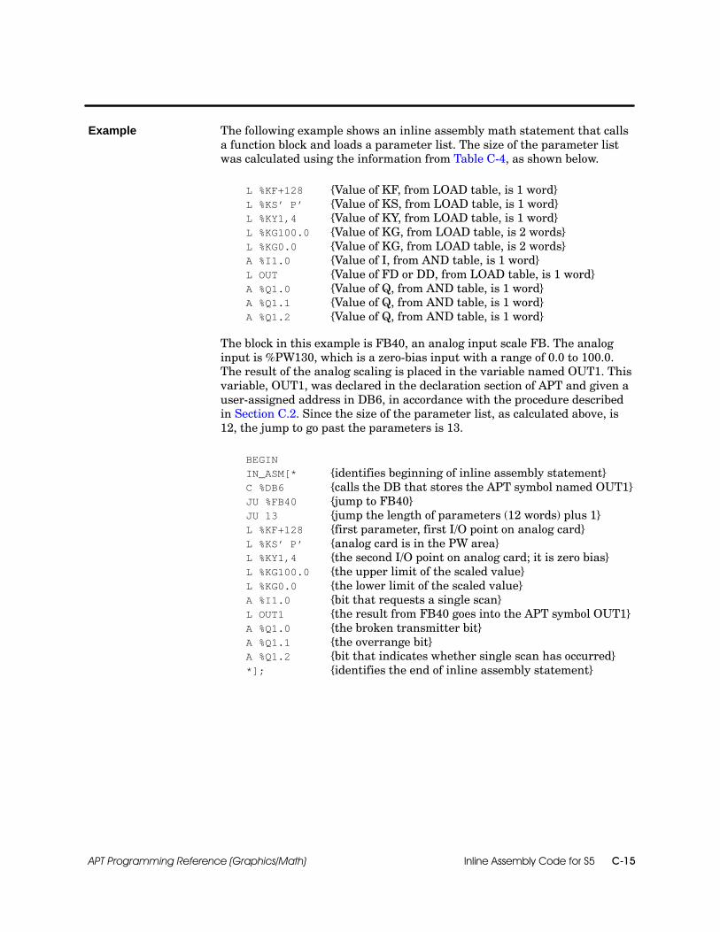
Inline Assembly Code for S5 C-15APT Programming Reference (Graphics/Math)
The following example shows an inline assembly math statement that callsa function block and loads a parameter list. The size of the parameter listwas calculated using the information from Table C-4, as shown below.
L %KF+128 {Value of KF, from LOAD table, is 1 word}L %KS’ P’ {Value of KS, from LOAD table, is 1 word}L %KY1,4 {Value of KY, from LOAD table, is 1 word}L %KG100.0 {Value of KG, from LOAD table, is 2 words}L %KG0.0 {Value of KG, from LOAD table, is 2 words}A %I1.0 {Value of I, from AND table, is 1 word}L OUT {Value of FD or DD, from LOAD table, is 1 word}A %Q1.0 {Value of Q, from AND table, is 1 word}A %Q1.1 {Value of Q, from AND table, is 1 word}A %Q1.2 {Value of Q, from AND table, is 1 word}
The block in this example is FB40, an analog input scale FB. The analoginput is %PW130, which is a zero-bias input with a range of 0.0 to 100.0.The result of the analog scaling is placed in the variable named OUT1. Thisvariable, OUT1, was declared in the declaration section of APT and given auser-assigned address in DB6, in accordance with the procedure describedin Section C.2. Since the size of the parameter list, as calculated above, is12, the jump to go past the parameters is 13.
BEGININ_ASM[* {identifies beginning of inline assembly statement}C %DB6 {calls the DB that stores the APT symbol named OUT1}JU %FB40 {jump to FB40}JU 13 {jump the length of parameters (12 words) plus 1}L %KF+128 {first parameter, first I/O point on analog card}L %KS’ P’ {analog card is in the PW area}L %KY1,4 {the second I/O point on analog card; it is zero bias}L %KG100.0 {the upper limit of the scaled value}L %KG0.0 {the lower limit of the scaled value}A %I1.0 {bit that requests a single scan}L OUT1 {the result from FB40 goes into the APT symbol OUT1}A %Q1.0 {the broken transmitter bit}A %Q1.1 {the overrange bit}A %Q1.2 {bit that indicates whether single scan has occurred}*]; {identifies the end of inline assembly statement}
Example

Inline Assembly Code for S5C-16 APT Programming Reference (Graphics/Math)
How to Incorporate Your Block (continued)
You can use the accumulators to pass the parameters of an external FB, FX,PB, SB, or OB. You must reserve FBs, FXs, PBs, and SBs in the CompilerControl File before you incorporate them into APT. You do not have toreserve OBs in the Compiler Control File.
Four accumulators are available for storage of the parameters of yourblocks; do not load more than four accumulators. Each time you load aparameter into Accumulator 1 it moves the other parameters over to thenext higher accumulator. If you want to load all four accumulators, followthese steps.
1. Load the first two parameters into Accumulator 1 and enter the ENTcommand.
2. Load the third parameter into Accumulator 1 and enter the ENTcommand.
3. Load the fourth parameter into Accumulator 1.
The first parameter moves to Accumulator 4, the second parametermoves to Accumulator 3, the third parameter moves to Accumulator 2,and the last parameter stays in Accumulator 1.
! WARNINGYou can load a maximum of four accumulators before you begin to overwritedata. Loading more than four accumulators could result in unpredictableoperation of the controller.
Unpredictable operation of the controller could result in death or serious injuryto personnel, and/or damage to equipment.
Do not load more than four parameters, total, to the accumulators.
Using theAccumulators

Inline Assembly Code for S5 C-17APT Programming Reference (Graphics/Math)
Follow this format to use an inline assembly math statement to load theaccumulators:
1. Enter the inline assembly identifier that indicates the beginning of thestatement.
IN_ASM[*
2. Load the accumulators.
See Section C.2 for examples of load statements for the various types ofparameter (direct addresses, symbolic names, bits, constants) that arepermitted.
3. Enter the jump to the FB, FX, PB, SB, or OB.
JU %FBxJU %FXxJU %PBxJU %SBxJU %OBx
where x is the number that identifies the FB, FX, PB, SB, or OB.
4. Enter the inline assembly identifier that indicates the end of thestatement.
*];
An inline assembly statement is a Math statement and must end in asemicolon.
Loading theAccumulators

Inline Assembly Code for S5C-18 APT Programming Reference (Graphics/Math)
How to Incorporate Your Block (continued)
This example shows an inline assembly math statement that loadsparameters for a cosine function block at FB102 into the accumulators. Boththe inputs and the results of the cosine function block are stored in theaccumulators. In this example, THETA is an angle that has already beendeclared in the declaration section of APT. COSTHETA is a variable thathas been declared in APT; it holds the result of the FB. Notice that THETAand COSTHETA do not have to have a user-assigned address, since they arepassed through the accumulators instead of through a parameter list.
BEGININ_ASM[* {identifies beginning of inline assembly statement}L THETA {load THETA into Accumulator 1}JU %FB102 {jump to the cosine FB}= %F250.2 {error flag}T COSTHETA {transfer result from Accumulator 1 to COSTHETA}*]; {identifies the end of inline assembly statement}
This code loads THETA into Accumulator 1 and then jumps to FB102. Thecosine of THETA is placed into Accumulator 1 and then transferred to thevariable COSTHETA. If the calculation is successful, FB102 sets RLO.
Example

Inline Assembly Code for S5 C-19APT Programming Reference (Graphics/Math)
If your direct address is a data word, you can call the data block (DB or DX)in the inline assembly math statement before you use the data word, as longas you have already reserved the DB or DX in the Compiler Control File.
If you declare a data word in the declaration section of APT, and assign it toa reserved DB or DX, you can use the left-hand byte and the right-handbyte. To specify the left-hand byte, you can either use the memory type DL.To specify the right-hand byte, use memory type DR.
The following example calls a data block, DB3, and loads the left-hand andright-hand bytes of data word 12.
BEGINC %DB3 {calls DB3}L %DB3:DL12 {loads left-hand byte of DW12}L %DB3:DR12 {loads right-hand byte of DW12}
You must issue the call to the DB/DX before the jump to an FB/FX if you areusing the DB/DX data as inputs to a parameter list.
Opening a DataBlock

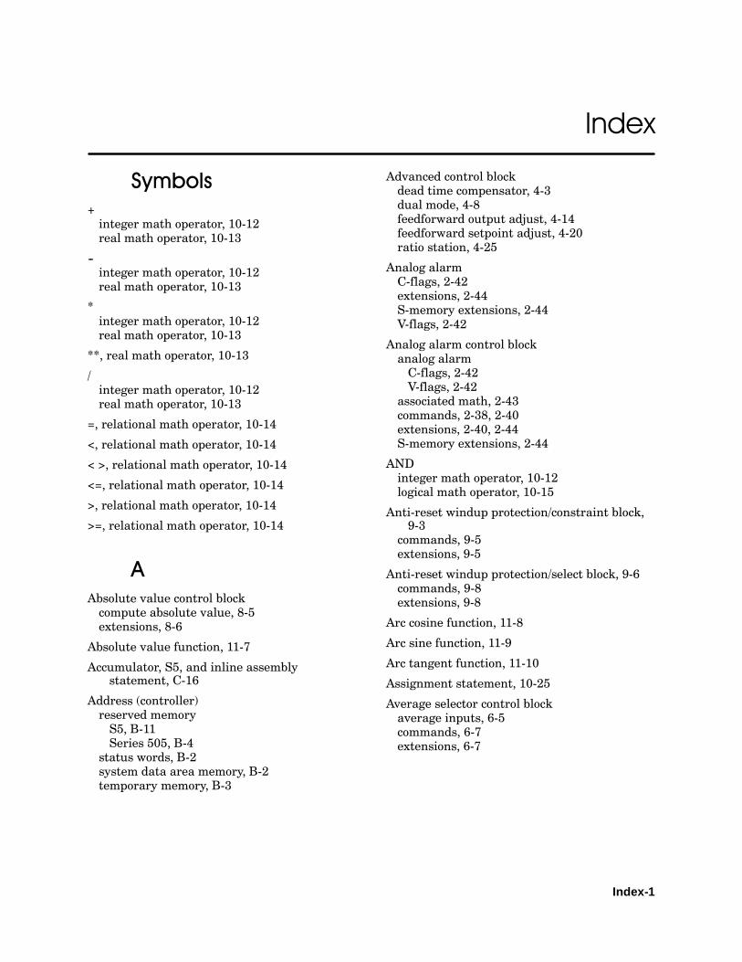
Index-1
Index
Symbols+integer math operator, 10-12real math operator, 10-13
--integer math operator, 10-12real math operator, 10-13
*integer math operator, 10-12real math operator, 10-13
**, real math operator, 10-13
/integer math operator, 10-12real math operator, 10-13
=, relational math operator, 10-14
<, relational math operator, 10-14
< >, relational math operator, 10-14
<=, relational math operator, 10-14
>, relational math operator, 10-14
>=, relational math operator, 10-14
AAbsolute value control blockcompute absolute value, 8-5extensions, 8-6
Absolute value function, 11-7
Accumulator, S5, and inline assemblystatement, C-16
Address (controller)reserved memoryS5, B-11Series 505, B-4
status words, B-2system data area memory, B-2temporary memory, B-3
Advanced control blockdead time compensator, 4-3dual mode, 4-8feedforward output adjust, 4-14feedforward setpoint adjust, 4-20ratio station, 4-25
Analog alarmC-flags, 2-42extensions, 2-44S-memory extensions, 2-44V-flags, 2-42
Analog alarm control blockanalog alarmC-flags, 2-42V-flags, 2-42
associated math, 2-43commands, 2-38, 2-40extensions, 2-40, 2-44S-memory extensions, 2-44
ANDinteger math operator, 10-12logical math operator, 10-15
Anti-reset windup protection/constraint block,9-3
commands, 9-5extensions, 9-5
Anti-reset windup protection/select block, 9-6commands, 9-8extensions, 9-8
Arc cosine function, 11-8
Arc sine function, 11-9
Arc tangent function, 11-10
Assignment statement, 10-25
Average selector control blockaverage inputs, 6-5commands, 6-7extensions, 6-7
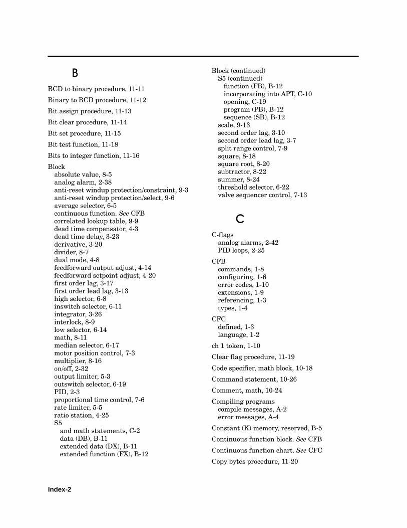
Index-2
BBCD to binary procedure, 11-11
Binary to BCD procedure, 11-12
Bit assign procedure, 11-13
Bit clear procedure, 11-14
Bit set procedure, 11-15
Bit test function, 11-18
Bits to integer function, 11-16
Blockabsolute value, 8-5analog alarm, 2-38anti-reset windup protection/constraint, 9-3anti-reset windup protection/select, 9-6average selector, 6-5continuous function. See CFBcorrelated lookup table, 9-9dead time compensator, 4-3dead time delay, 3-23derivative, 3-20divider, 8-7dual mode, 4-8feedforward output adjust, 4-14feedforward setpoint adjust, 4-20first order lag, 3-17first order lead lag, 3-13high selector, 6-8inswitch selector, 6-11integrator, 3-26interlock, 8-9low selector, 6-14math, 8-11median selector, 6-17motor position control, 7-3multiplier, 8-16on/off, 2-32output limiter, 5-3outswitch selector, 6-19PID, 2-3proportional time control, 7-6rate limiter, 5-5ratio station, 4-25S5and math statements, C-2data (DB), B-11extended data (DX), B-11extended function (FX), B-12
Block (continued)S5 (continued)function (FB), B-12incorporating into APT, C-10opening, C-19program (PB), B-12sequence (SB), B-12
scale, 9-13second order lag, 3-10second order lead lag, 3-7split range control, 7-9square, 8-18square root, 8-20subtractor, 8-22summer, 8-24threshold selector, 6-22valve sequencer control, 7-13
CC-flagsanalog alarms, 2-42PID loops, 2-25
CFBcommands, 1-8configuring, 1-6error codes, 1-10extensions, 1-9referencing, 1-3types, 1-4
CFCdefined, 1-3language, 1-2
ch 1 token, 1-10
Clear flag procedure, 11-19
Code specifier, math block, 10-18
Command statement, 10-26
Comment, math, 10-24
Compiling programscompile messages, A-2error messages, A-4
Constant (K) memory, reserved, B-5
Continuous function block. See CFB
Continuous function chart. See CFC
Copy bytes procedure, 11-20
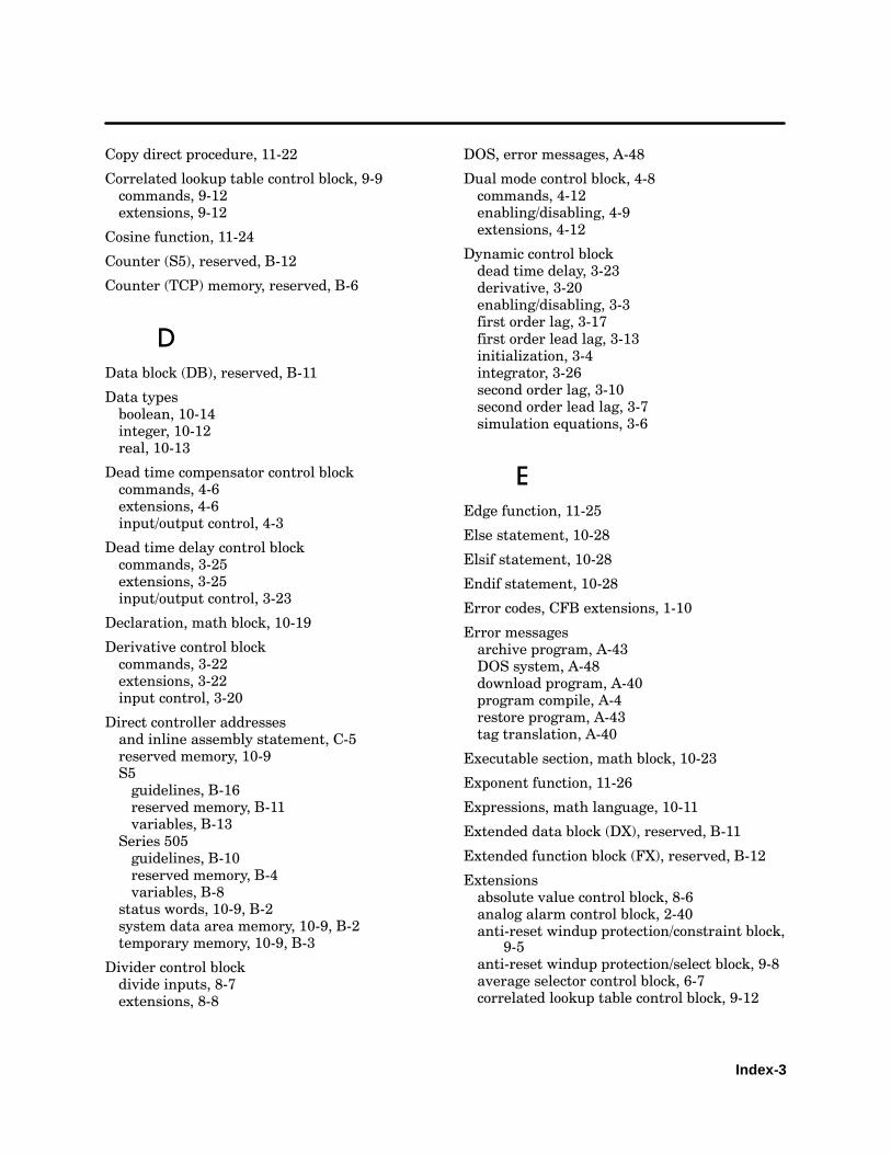
Index-3
Copy direct procedure, 11-22
Correlated lookup table control block, 9-9commands, 9-12extensions, 9-12
Cosine function, 11-24
Counter (S5), reserved, B-12
Counter (TCP) memory, reserved, B-6
DData block (DB), reserved, B-11
Data typesboolean, 10-14integer, 10-12real, 10-13
Dead time compensator control blockcommands, 4-6extensions, 4-6input/output control, 4-3
Dead time delay control blockcommands, 3-25extensions, 3-25input/output control, 3-23
Declaration, math block, 10-19
Derivative control blockcommands, 3-22extensions, 3-22input control, 3-20
Direct controller addressesand inline assembly statement, C-5reserved memory, 10-9S5guidelines, B-16reserved memory, B-11variables, B-13
Series 505guidelines, B-10reserved memory, B-4variables, B-8
status words, 10-9, B-2system data area memory, 10-9, B-2temporary memory, 10-9, B-3
Divider control blockdivide inputs, 8-7extensions, 8-8
DOS, error messages, A-48
Dual mode control block, 4-8commands, 4-12enabling/disabling, 4-9extensions, 4-12
Dynamic control blockdead time delay, 3-23derivative, 3-20enabling/disabling, 3-3first order lag, 3-17first order lead lag, 3-13initialization, 3-4integrator, 3-26second order lag, 3-10second order lead lag, 3-7simulation equations, 3-6
EEdge function, 11-25
Else statement, 10-28
Elsif statement, 10-28
Endif statement, 10-28
Error codes, CFB extensions, 1-10
Error messagesarchive program, A-43DOS system, A-48download program, A-40program compile, A-4restore program, A-43tag translation, A-40
Executable section, math block, 10-23
Exponent function, 11-26
Expressions, math language, 10-11
Extended data block (DX), reserved, B-11
Extended function block (FX), reserved, B-12
Extensionsabsolute value control block, 8-6analog alarm control block, 2-40anti-reset windup protection/constraint block,
9-5anti-reset windup protection/select block, 9-8average selector control block, 6-7correlated lookup table control block, 9-12

Index-4
Extensions (continued)dead time compensator control block, 4-6dead time delay control block, 3-25derivative control block, 3-22divider control block, 8-8dual mode control block, 4-12error codes, 1-10feedforward output adjust control block, 4-18feedforward setpoint adjust control block,
4-23first order lag control block, 3-19first order lead lag control block, 3-16high selector control block, 6-10inswitch selector control block, 6-13integrator control block, 3-28low selector control block, 6-16math control block, 8-15median selector control block, 6-18motor position control block, 7-5multiplier control block, 8-17on/off control block, 2-36output limiter control block, 5-4outswitch selector control block, 6-21PID control block, 2-23, 2-27proportional time control block, 7-8rate limiter control block, 5-7ratio station control block, 4-27RTD status, 2-31scale control block, 9-15second order lag control block, 3-12second order lead lag control block, 3-9split range control block, 7-12square control block, 8-19square root control block, 8-21subtractor control block, 8-23summer control block, 8-25system-defined, 10-8thermocouple status, 2-31threshold selector control block, 6-24valve sequencer control block, 7-16
FFeedforward output adjust control blockcommands, 4-17extensions, 4-18output control, 4-14
Feedforward setpoint adjust control blockcommands, 4-23extensions, 4-23setpoint control, 4-20
First order lag control blockcommands, 3-19extensions, 3-19input/output control, 3-17
First order lead lag control blockcommands, 3-16extensions, 3-16input/output control, 3-13
Flag byte, reserved, B-12
Flag, APT, PID control block, 2-21
Forced role swap procedure, 11-27
Fraction function, 11-28
Function block (FB), reserved, B-12
Function statement, 10-26
HHigh selector control blockcommands, 6-10extensions, 6-10high input, 6-8
II control block. See PID control block
Identifiers, math language, 10-7
If statement, 10-28
Immediate read input procedure, 11-35
Immediate write output procedure, 11-36
IN_ASM statement, C-2
Inline assembly (in_asm) statementaccumulator, C-16defined, C-2parameters, C-5
Inswitch selector control blockcommands, 6-13extensions, 6-13select input, 6-11

Index-5
Integer math operators, 10-12
Integer to bits procedure, 11-32
Integer to real function, 11-34
Integrator control blockcommands, 3-28extensions, 3-28input/output control, 3-26
Interlock control block, create interlock, 8-9
Interpolate procedure, 11-30
KKey words, math language, 10-6
LLadder (L) memory, reserved, B-4
Language, math. SeeMath language
Languages, CFC, 1-2
Latch procedure, 11-37
Lead lag procedure, 11-38
Left shift function, 11-40
Limit procedure, 11-41
Limiter control blockenabling/disabling, 5-2output limiter, 5-3rate limiter, 5-5
Load array procedure, 11-42
Logarithm (LN) function, 11-46
Logarithm (LOG) function, 11-47
Logical math operators, 10-15
Lookup table procedure, 11-44
Loopalgorithm, 2-4associated math, 2-17C-flags, 2-25controller options, 2-15direct-acting, 2-15extensions, 2-29freeze bias, 2-16output, 2-13
Loop (continued)process variable, 2-9reverse-acting, 2-15S-memory extensions, 2-29setpoint, 2-11status, 2-27tuning parameters, 2-19V-flags, 2-25
Low selector control blockcommands, 6-16extensions, 6-16low input, 6-14
MMap tuning and alarm data to S-memory, PID
blocks, 2-30
Math blockRLL code, 10-4SFPGM code, 10-4
Math control blockabsolute value, 8-5commands, 8-15divider, 8-7enabling/disabling, 8-14extensions, 8-15interlock, 8-9math, 8-11multiplier, 8-16square, 8-18square root, 8-20subtractor, 8-22summer, 8-24user-defined math, 8-11
Math languagedata typesboolean, 10-14integer, 10-12real, 10-13
defined, 10-2direct controller addresses, 10-9expressions, 10-11functions, 11-3ABS, 11-7ARCCOS, 11-8ARCSIN, 11-9ARCTAN, 11-10BITS_TO_INT, 11-16

Index-6
Math language (continued)functions (continued)BITTEST, 11-18COS, 11-24EDGE, 11-25EXP, 11-26FRAC, 11-28INT_TO_REAL, 11-34LEFTSHIFT, 11-40LN, 11-46LOG, 11-47RIGHTSHIFT, 11-56ROUND, 11-57SIN, 11-64SQRT, 11-65TAN, 11-66TRUNC, 11-67
identifiers, 10-7key words, 10-6math block structure, 10-16code specifier, 10-18declaration section, 10-19executable section, 10-23
PRAGMA, 10-18precedence level, 10-11procedures, 11-3BCDBIN, 11-11BINBCD, 11-12BIT_ASSIGN, 11-13BITCLEAR, 11-14BITSET, 11-15CLEAR, 11-19COPY_BYTES, 11-20COPY_DIRECT, 11-22FRS, 11-27INT_TO_BITS, 11-32INTERPOLATE, 11-30IREAD, 11-35IWRITE, 11-36LATCH, 11-37LEAD_LAG, 11-38LIMIT, 11-41LOAD_ARRAY, 11-42LOOKUP_TABLE, 11-44MAX, 11-48MIN, 11-49MINMAX, 11-50ON, 11-51PACK_BITS, 11-52PBITS_TO_INT, 11-53PROUND, 11-54
Math language (continued)procedures (continued)PTRUNC, 11-55SCALE, 11-58SETSSI, 11-62UNPACK_BITS, 11-68UNSCALE, 11-70
subroutines, 11-6
Math operatorsinteger, 10-12logical, 10-15real, 10-13relational, 10-14
Math statementsassignment, 10-25command, 10-26comments, 10-24else, 10-28elsif, 10-28endif, 10-28function, 10-26if, 10-28inline assemblyand S5 blocks, C-2formatting, C-4parameters, C-5
print, 10-26procedure, 10-26while, 10-30
Maximum value procedure, 11-48
Median selector control blockcommands, 6-18extensions, 6-18median input, 6-17
MemoryS5, system data area (RS), B-2Series 505reserved, B-4status word, B-2temporary, B-3
Messagesarchive program error, A-43compile error, A-4DOS system, A-48download error, A-40restore program error, A-43tag translate error, A-40
Minimum value procedure, 11-49
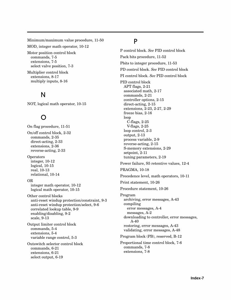
Index-7
Minimum/maximum value procedure, 11-50
MOD, integer math operator, 10-12
Motor position control blockcommands, 7-5extensions, 7-5select valve position, 7-3
Multiplier control blockextensions, 8-17multiply inputs, 8-16
NNOT, logical math operator, 10-15
OOn flag procedure, 11-51
On/off control block, 2-32commands, 2-35direct-acting, 2-33extensions, 2-36reverse-acting, 2-33
Operatorsinteger, 10-12logical, 10-15real, 10-13relational, 10-14
ORinteger math operator, 10-12logical math operator, 10-15
Other control blocksanti-reset windup protection/constraint, 9-3anti-reset windup protection/select, 9-6correlated lookup table, 9-9enabling/disabling, 9-2scale, 9-13
Output limiter control blockcommands, 5-4extensions, 5-4variable range control, 5-3
Outswitch selector control blockcommands, 6-21extensions, 6-21select output, 6-19
PP control block. See PID control block
Pack bits procedure, 11-52
Pbits to integer procedure, 11-53
PD control block. See PID control block
PI control block. See PID control block
PID control blockAPT flags, 2-21associated math, 2-17commands, 2-21controller options, 2-15direct-acting, 2-15extensions, 2-23, 2-27, 2-29freeze bias, 2-16loopC-flags, 2-25V-flags, 2-25
loop control, 2-3output, 2-13process variable, 2-9reverse-acting, 2-15S-memory extensions, 2-29setpoint, 2-11tuning parameters, 2-19
Power failure, S5 retentive values, 12-4
PRAGMA, 10-18
Precedence level, math operators, 10-11
Print statement, 10-26
Procedure statement, 10-26
Programarchiving, error messages, A-43compilingerror messages, A-4messages, A-2
downloading to controller, error messages,A-40
restoring, error messages, A-43validating, error messages, A-48
Program block (PB), reserved, B-12
Proportional time control block, 7-6commands, 7-8extensions, 7-8
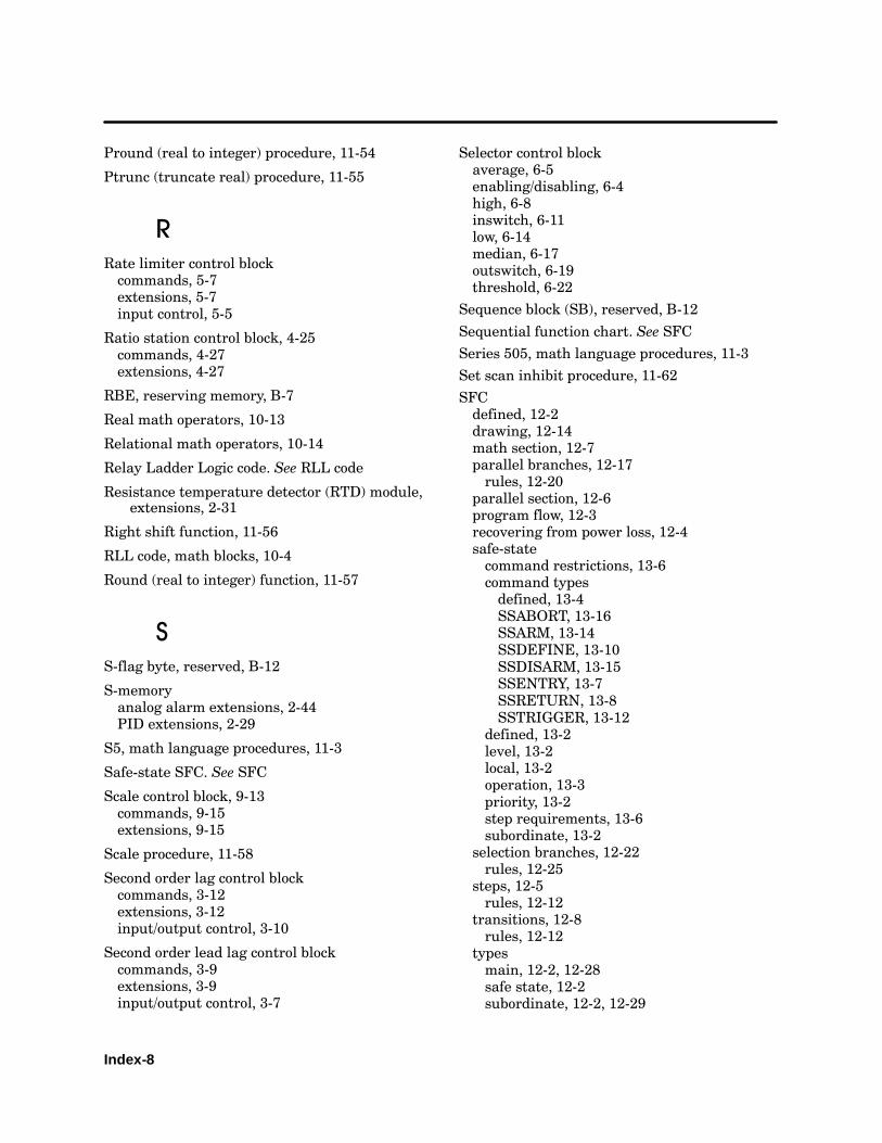
Index-8
Pround (real to integer) procedure, 11-54
Ptrunc (truncate real) procedure, 11-55
RRate limiter control blockcommands, 5-7extensions, 5-7input control, 5-5
Ratio station control block, 4-25commands, 4-27extensions, 4-27
RBE, reserving memory, B-7
Real math operators, 10-13
Relational math operators, 10-14
Relay Ladder Logic code. See RLL code
Resistance temperature detector (RTD) module,extensions, 2-31
Right shift function, 11-56
RLL code, math blocks, 10-4
Round (real to integer) function, 11-57
SS-flag byte, reserved, B-12
S-memoryanalog alarm extensions, 2-44PID extensions, 2-29
S5, math language procedures, 11-3
Safe-state SFC. See SFC
Scale control block, 9-13commands, 9-15extensions, 9-15
Scale procedure, 11-58
Second order lag control blockcommands, 3-12extensions, 3-12input/output control, 3-10
Second order lead lag control blockcommands, 3-9extensions, 3-9input/output control, 3-7
Selector control blockaverage, 6-5enabling/disabling, 6-4high, 6-8inswitch, 6-11low, 6-14median, 6-17outswitch, 6-19threshold, 6-22
Sequence block (SB), reserved, B-12
Sequential function chart. See SFC
Series 505, math language procedures, 11-3
Set scan inhibit procedure, 11-62
SFCdefined, 12-2drawing, 12-14math section, 12-7parallel branches, 12-17rules, 12-20
parallel section, 12-6program flow, 12-3recovering from power loss, 12-4safe-statecommand restrictions, 13-6command typesdefined, 13-4SSABORT, 13-16SSARM, 13-14SSDEFINE, 13-10SSDISARM, 13-15SSENTRY, 13-7SSRETURN, 13-8SSTRIGGER, 13-12
defined, 13-2level, 13-2local, 13-2operation, 13-3priority, 13-2step requirements, 13-6subordinate, 13-2
selection branches, 12-22rules, 12-25
steps, 12-5rules, 12-12
transitions, 12-8rules, 12-12
typesmain, 12-2, 12-28safe state, 12-2subordinate, 12-2, 12-29
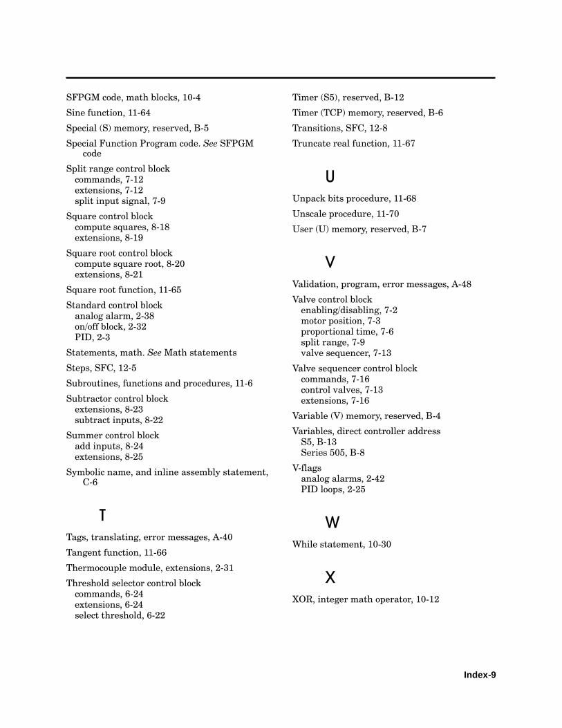
Index-9
SFPGM code, math blocks, 10-4
Sine function, 11-64
Special (S) memory, reserved, B-5
Special Function Program code. See SFPGMcode
Split range control blockcommands, 7-12extensions, 7-12split input signal, 7-9
Square control blockcompute squares, 8-18extensions, 8-19
Square root control blockcompute square root, 8-20extensions, 8-21
Square root function, 11-65
Standard control blockanalog alarm, 2-38on/off block, 2-32PID, 2-3
Statements, math. SeeMath statements
Steps, SFC, 12-5
Subroutines, functions and procedures, 11-6
Subtractor control blockextensions, 8-23subtract inputs, 8-22
Summer control blockadd inputs, 8-24extensions, 8-25
Symbolic name, and inline assembly statement,C-6
TTags, translating, error messages, A-40
Tangent function, 11-66
Thermocouple module, extensions, 2-31
Threshold selector control blockcommands, 6-24extensions, 6-24select threshold, 6-22
Timer (S5), reserved, B-12
Timer (TCP) memory, reserved, B-6
Transitions, SFC, 12-8
Truncate real function, 11-67
UUnpack bits procedure, 11-68
Unscale procedure, 11-70
User (U) memory, reserved, B-7
VValidation, program, error messages, A-48
Valve control blockenabling/disabling, 7-2motor position, 7-3proportional time, 7-6split range, 7-9valve sequencer, 7-13
Valve sequencer control blockcommands, 7-16control valves, 7-13extensions, 7-16
Variable (V) memory, reserved, B-4
Variables, direct controller addressS5, B-13Series 505, B-8
V-flagsanalog alarms, 2-42PID loops, 2-25
WWhile statement, 10-30
XXOR, integer math operator, 10-12


Customer Response
We would like to know what you think about our user manuals so that we can serve you better.How would you rate the quality of our manuals?
Excellent Good Fair Poor
AccuracyOrganizationClarityCompletenessGraphicsExamplesOverall designSizeIndex
Would you be interested in giving us more detailed comments about our manuals?
Yes! Please send me a questionnaire.
No. Thanks anyway.
Your Name:
Title:
Telephone Number: ( )
Company Name:
Company Address:
Manual Name: APT Programming Reference (Graphics/Math) Manual Edition: Tenth
Manual Assembly Number: 2801047--0007 Date: 4/01
Order Number: PPX:APT--8102--10
BUSINESS REPLY MAILFIRST CLASS PERMIT NO.3 JOHNSON CITY, TN
FOLD
FOLD
POSTAGE WILL BE PAID BY ADDRESSEE
NO POSTAGENECESSARYIF MAILEDIN THE
UNITED STATES
ATTN TECHNICAL COMMUNICATIONS M/S 1255SIEMENS ENERGY & AUTOMATION INCPO BOX 1255JOHNSON CITY TN 37605--1255
SIEMENS ENERGY & AUTOMATION INC3000 BILL GARLAND ROADPO BOX 1255JOHNSON CITY TN 37605--1255


