SIMATIC NET S7-CPs for Industrial Ethernet Manual Part BL1 LED displays Mode selector Network Gateway IE/PB Link PN IO 6GK1 411-5AB00 Version 1 or higher (Firmware Version V 1.0) IE/PB Link Attachment to Industrial Ethernet 8-pin RJ-45 jack Attachment to PROFIBUS: 9-pin D-sub female connector C-PLUG
Transcript
SIMATIC NET
S7-CPs for Industrial Ethernet
Manual Part BL1
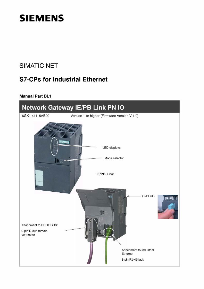
LED displays
Mode selector
Network Gateway IE/PB Link PN IO6GK1 411-5AB00 Version 1 or higher (Firmware Version V 1.0)
IE/PB Link
Attachment to IndustrialEthernet
8-pin RJ-45 jack
Attachment to PROFIBUS:
9-pin D-sub femaleconnector
C-PLUG
Notes on the Product
BL1-2Network Gateway IE/PB Link PN IO for Industrial Ethernet / Manual Part BL1
Release 5/2005
C79000-G8976-C199-02
Notes on the Product
Product Names:
This description contains information on the product
� IE/PB Link PN IO order no.: 6GK1 411-5AB00
Product Information Accompanying the Product
Note
All the notices in the Product Information Bulletin shipped with this device arevalid and must be adhered to.
Contents
BL1-3Network Gateway IE/PB Link PN IO for Industrial Ethernet / Manual Part BL1Release 5/2005
C79000-G8976-C199-02
Contents
Contents - Part A
S7-CPs - General Information See General Part. . . . . . . . . . . . . . . . . . . . . . . .
Note
Please remember that Part A of the manual also belongs to the description of theCP / IE/PB Link. Among other things, it contains explanations of the safetynotices, the references to literature, and general information that applies to all S7CPs / IE/PB Link for Industrial Ethernet.
The version of the General Part of the manual belonging to this Part B is version12/2003.
You can also obtain the current Part A from the Internet:
BL1-5Network Gateway IE/PB Link PN IO for Industrial Ethernet / Manual Part BL1Release 5/2005
C79000-G8976-C199-02
1 Properties and Services
Application
The IE/PB Link PN IO is a gateway that links Industrial Ethernet (managementlevel) and PROFIBUS (cell level / field level).
The IE/PB Link PN IO allows access to all PROFIBUS DP slaves on thesubordinate PROFIBUS; DP slaves complying with PROFIBUS DP-V0 aresupported and, as of firmware version V2.0, also DP slaves complying with theDP-V1 standard and Siemens DP slaves.
The design of the IE/PB Link PN IO matches the components of the SIMATICS7-300 range of devices.
You can use the IE/PB Link PN IO in the following modes:
� Gateway as PROFINET IO proxy
� Gateway in standard operation
Services
In these modes, the following communication services are supported:
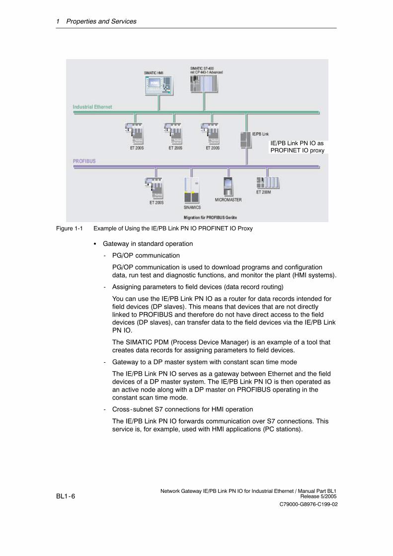
� Gateway as PROFINET IO proxy
The IE/PB Link PN IO is an important component for the operation ofPROFINET IO. It connects the PROFINET IO controllers to Industrial Ethernetand the PROFINET IO devices (DP slaves to PROFIBUS).
From the perspective of the PROFINET IO controller on Industrial Ethernet,there is no difference between accessing PROFINET IO devices connected toIndustrial Ethernet and PROFIBUS DP slaves connected to PROFIBUS DP.
The IE/PB Link PN IO takes on the role of a proxy for the DP slaves connectedto PROFIBUS DP.
1 Properties and Services
BL1-6Network Gateway IE/PB Link PN IO for Industrial Ethernet / Manual Part BL1
Release 5/2005
C79000-G8976-C199-02
IE/PB Link PN IO as PROFINET IO proxy
Figure 1-1 Example of Using the IE/PB Link PN IO PROFINET IO Proxy
� Gateway in standard operation
- PG/OP communication
PG/OP communication is used to download programs and configurationdata, run test and diagnostic functions, and monitor the plant (HMI systems).
- Assigning parameters to field devices (data record routing)
You can use the IE/PB Link PN IO as a router for data records intended forfield devices (DP slaves). This means that devices that are not directlylinked to PROFIBUS and therefore do not have direct access to the fielddevices (DP slaves), can transfer data to the field devices via the IE/PB LinkPN IO.
The SIMATIC PDM (Process Device Manager) is an example of a tool thatcreates data records for assigning parameters to field devices.
- Gateway to a DP master system with constant scan time mode
The IE/PB Link PN IO serves as a gateway between Ethernet and the fielddevices of a DP master system. The IE/PB Link PN IO is then operated asan active node along with a DP master on PROFIBUS operating in theconstant scan time mode.
- Cross-subnet S7 connections for HMI operation
The IE/PB Link PN IO forwards communication over S7 connections. Thisservice is, for example, used with HMI applications (PC stations).
1 Properties and Services
BL1-7Network Gateway IE/PB Link PN IO for Industrial Ethernet / Manual Part BL1Release 5/2005
C79000-G8976-C199-02
PROFIBUS-DP
Ind. Ethernet
S7-400 PC
PC
SITRANSET 200XET 200SDrive
DP/PA LinkPN IO
IE/PB LinkPN IO
Panel PC 670
S7-300
Figure 1-2 Example of Using the IE/PB Link PN IO in the Standard Mode
Further Properties
� Fast Ethernet
The IE/PB Link PN IO has a 10/100 Mbps half/full duplex port with“Autonegotiation” for automatic switchover.
� Time-of-day synchronization
If a time master exists on Industrial Ethernet, the IE/PB Link PN IO uses thetime frames for time stamping the diagnostic buffer entries and process signals.
Forwarding time-of-day frames
The IE/PB Link PN IO can forward the time-of-day frames received from a timetransmitter as follows:
- from Ethernet to PROFIBUS
- From PROFIBUS to Ethernet
� Downloading firmware
The IE/PB Link PN IO supports the updating of firmware (FW) with theFirmware Loader.
A firmware update can be downloaded at any time from the PC/PG via theEthernet port.
1 Properties and Services
BL1-8Network Gateway IE/PB Link PN IO for Industrial Ethernet / Manual Part BL1
Release 5/2005
C79000-G8976-C199-02
� Option: C-PLUG as exchangeable medium for the project engineering data
The IE/PB Link PN IO supports storage of the project engineering data on aC-PLUG. This allows simple replacement of a defect module by inserting theC-PLUG in the new module.
� Direct Data Exchange
The IE/PB LINK PN IO supports direct data exchange between DP slaves inassigned DP master systems. This means that applications with PROFISAFEare also possible.
Configuration
You can configure the IE/PB Link PN IO over Industrial Ethernet or PROFIBUS.
You can perform the project engineering for the IE/PB Link PN IO for all modesover Industrial Ethernet. If you use the device as a standard gateway, it is alsopossible to change / download the project engineering data over PROFIBUS.
You require the STEP 7 configuration software with a version as shown below:
Table 1-1
Version STEP 7/NCM S7 *) Functionality of the IE/PB Link PN IO (see also Chapter 8)
V5.3 SP1 The full functionality of the V1.0 firmware can be used.
V5.3 SP2 Hotfix 1 with HSP 1007 The full functionality of a module with firmware version V2.0 can beused.
*) As of V5.3, NCM is automatically part of the basic installation, as of this version no distinction betweenEthernet and PROFIBUS is made.
2 Construction
BL1-9Network Gateway IE/PB Link PN IO for Industrial Ethernet / Manual Part BL1Release 5/2005
C79000-G8976-C199-02
2 Construction
LED displays
Mode selector
Hinged front panel
Figure 2-1
The module has been designed to match the components of the S7-300programmable logic controller and has the following features:
� Double-width module for simple installation in the S7-300 rack
� The control and display elements are all on the front panel; some of the LEDsare behind the hinged front panel.
� No fan necessary
Behind the front panel, you will find:
� 8-pin RJ-45 jack to connect the IE/PB Link to Ind. Ethernet;
� 9-pin D-sub female connector for attaching the IE/PB Link to PROFIBUS
� Further LED displays;
� Slider for setting the chassis ground connection
On the back of the device, there is a slot for an external memory module(C-PLUG); the slot is accessible only after removing the device from the rack.
Notice
If you replace the C-PLUG, make sure that the power supply is off!
3 Installation and Commissioning
BL1-10Network Gateway IE/PB Link PN IO for Industrial Ethernet / Manual Part BL1
Release 5/2005
C79000-G8976-C199-02
3 Installation and Commissioning
3.1 How to...
Follow the steps as shown in the graphic below; please make sure that you readthe supplementary notes in this section. Installation and configuration can initiallybe considered as independent procedures.
Install the IE/PB Link PN IO on theS7 standard rail (S7-300).
If required, the C-PLUG must first beinserted in the back of the device.
Connect the power supply(check the setting of the slider forthe chassis ground connection).
Connect the IE/PB Link PN IO toEthernet and PROFIBUS.
Install the SIMATIC STEP 7configuration software on a PG/PC.
Configure the IE/PB LinkPN IO as an S7-300
station with HW Config.
Switch the power supply on.
Download the database(configuration) from STEP 7 to
the IE/PB Link PN IO.
Configuration: (see also Chapter 4):Installation:
Assign an IP address tothe IE/PB Link PN IO.
Configure the IE/PB LinkPN IO as an IO device in
a PN IO system(proxy with attached DP
master system)
Use as a gatewayonly
See Section4.1
Use as a PROFINET IOdevice and as gateway
See Section4.2
Download or update thedatabase (configuration) of thecorresponding PROFINET IO
controller
Assign a device name tothe IE/PB Link PN IO.
3 Installation and Commissioning
BL1-11Network Gateway IE/PB Link PN IO for Industrial Ethernet / Manual Part BL1Release 5/2005
C79000-G8976-C199-02
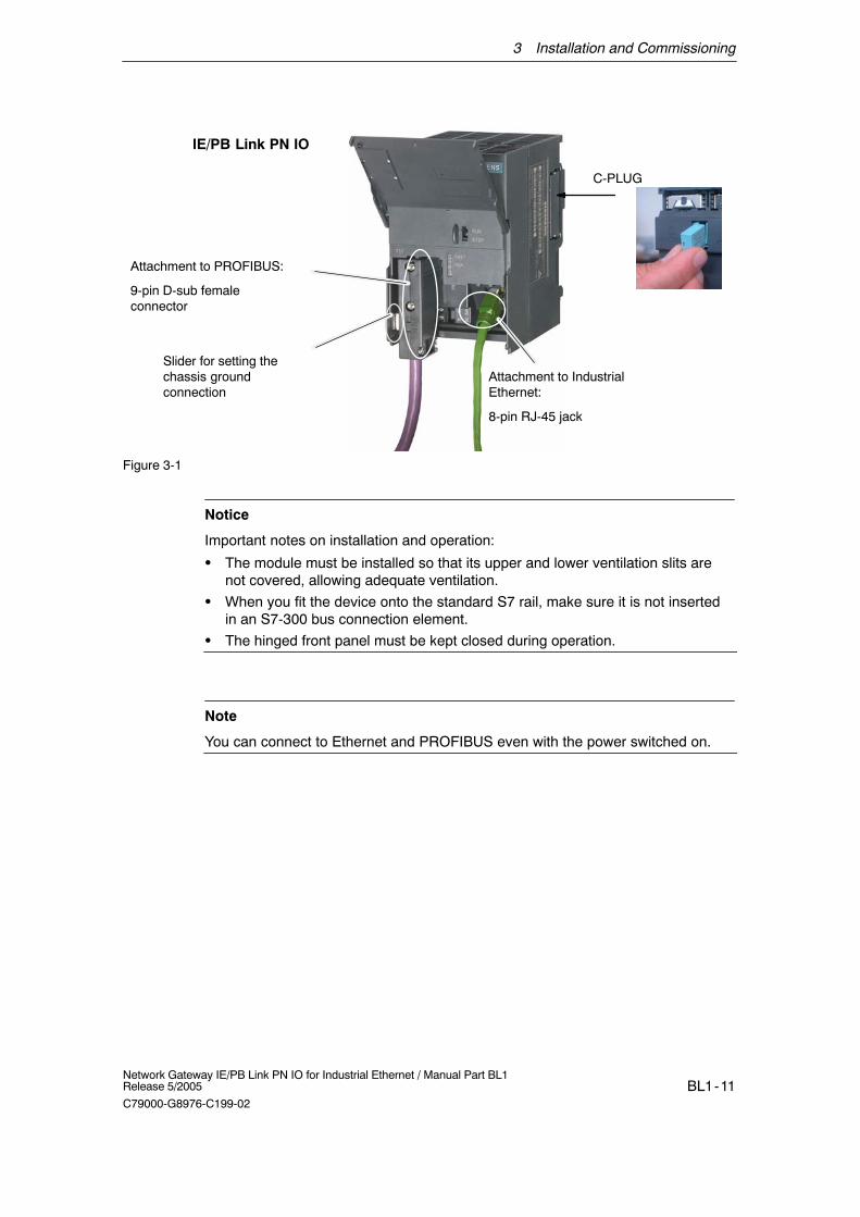
IE/PB Link PN IO
Attachment to PROFIBUS:
9-pin D-sub femaleconnector
Slider for setting thechassis groundconnection
Attachment to IndustrialEthernet:
8-pin RJ-45 jack
C-PLUG
Figure 3-1
Notice
Important notes on installation and operation:
� The module must be installed so that its upper and lower ventilation slits arenot covered, allowing adequate ventilation.
� When you fit the device onto the standard S7 rail, make sure it is not insertedin an S7-300 bus connection element.
� The hinged front panel must be kept closed during operation.
Note
You can connect to Ethernet and PROFIBUS even with the power switched on.
3 Installation and Commissioning
BL1-12Network Gateway IE/PB Link PN IO for Industrial Ethernet / Manual Part BL1
Release 5/2005
C79000-G8976-C199-02
Ground/Chassis Ground Concept
Notice
Please keep to the instructions on the grounding and chassis concept in theinstallation instructions for SIMATIC S7-300/S7-400 LEERER MERKER.
Behind the hinged panel on the left of the device, you will see a slider withwhich you can connect or disconnect the chassis ground of the 24 V powersupply with reference ground.
- Slider pushed in: chassis and reference ground connected (note: the slidermust be felt to lock in place).
- Slider pulled out: No connection between chassis and reference ground
When shipped: Slider pushed in
Use a screwdriver to set the slider.
PG/PC Connection
You can connect the PG when configuring the CP as follows:
� via PROFIBUS
You can only configure the IE/PB Link PN IO via PROFIBUS after it has beenassigned its PROFIBUS address. Please follow the instructions for addressingin Chapter 4.
� via Industrial Ethernet
You can only configure the IE/PB Link PN IO via Industrial Ethernet after it hasbeen assigned its IP address. Please follow the instructions for addressing inChapter 4.
Module Accessories
The accessories required to connect the IE/PB Link PN IO to an Industrial Ethernetand PROFIBUS LAN (S7 standard rail, power supply) must be ordered extra.
The optional C-PLUG can also be ordered separately.
For more detailed information and ordering data, refer to the Catalog IK PI.
3 Installation and Commissioning
BL1-13Network Gateway IE/PB Link PN IO for Industrial Ethernet / Manual Part BL1Release 5/2005
C79000-G8976-C199-02
3.2 C-PLUG (Configuration Plug)
C-Plug Removable Memory Medium As an Alternative to Flash Memory
The IE/PB Link PN IO has an internal flash memory for storage of the projectengineering data. As an option, the device can be operated with a C-PLUG(configuration plug) removable memory medium.
The IE/PB Link PN IO can be operated with or without a C-PLUG. Theexisting flash memory is then only used when no C-PLUG is inserted.
If a C-PLUG is inserted, the project engineering data is always stored on it.This simplifies replacement of modules. By simply exchanging the C-PLUG, all thedata can be transferred to the replacement module.
Notice
� If a C-PLUG is inserted, that does not contain valid formatting or no valid datafor the IE/PB Link PN IO, the IE/PB Link PN IO will not start up! Devicestatus: “STOP with error”.In this case, you must reformat the C-PLUG (with NCM diagnostics) or replaceit with a C-PLUG containing valid data.
� The C-PLUG may only be inserted for removed when the power is turned off!
Figure 3-2 Fitting a C-PLUG in the IE/PB Link PN IO and Removing a C-PLUG from the IE/PB Link PNIO using a Screwdriver
Working with and without a C-PLUG
The following table provides you an overview of how data is transferred tothe C-PLUG. The following situations must be distinguished:
� As shipped - operation without C-PLUG
� A C-PLUG is inserted in a module in the status as shipped
� A C-PLUG is inserted in an already installed module
3 Installation and Commissioning
BL1-14Network Gateway IE/PB Link PN IO for Industrial Ethernet / Manual Part BL1
Release 5/2005
C79000-G8976-C199-02
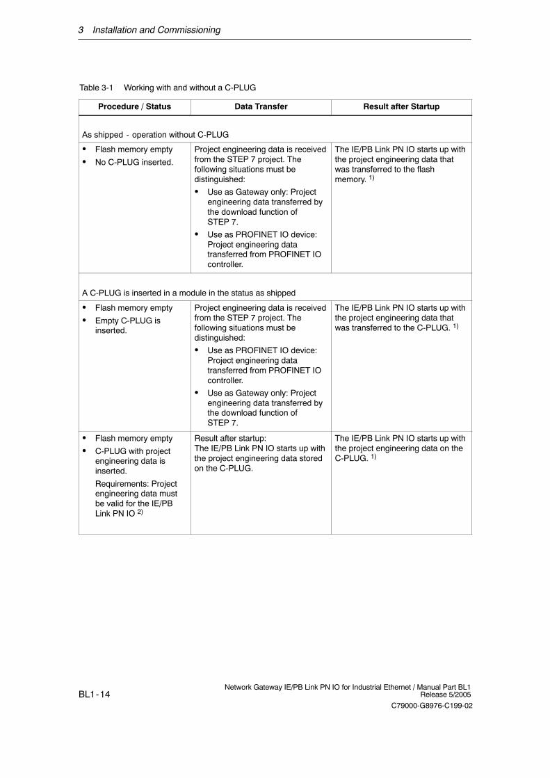
Table 3-1 Working with and without a C-PLUG
Procedure / Status Data Transfer Result after Startup
As shipped - operation without C-PLUG
� Flash memory empty
� No C-PLUG inserted.
Project engineering data is receivedfrom the STEP 7 project. Thefollowing situations must bedistinguished:
� Use as Gateway only: Projectengineering data transferred bythe download function ofSTEP 7.
� Use as PROFINET IO device:Project engineering datatransferred from PROFINET IOcontroller.
The IE/PB Link PN IO starts up withthe project engineering data thatwas transferred to the flashmemory. 1)
A C-PLUG is inserted in a module in the status as shipped
� Flash memory empty
� Empty C-PLUG isinserted.
Project engineering data is receivedfrom the STEP 7 project. Thefollowing situations must bedistinguished:
� Use as PROFINET IO device:Project engineering datatransferred from PROFINET IOcontroller.
� Use as Gateway only: Projectengineering data transferred bythe download function ofSTEP 7.
The IE/PB Link PN IO starts up withthe project engineering data thatwas transferred to the C-PLUG. 1)
� Flash memory empty
� C-PLUG with projectengineering data isinserted.
Requirements: Projectengineering data mustbe valid for the IE/PBLink PN IO 2)
Result after startup:The IE/PB Link PN IO starts up withthe project engineering data storedon the C-PLUG.
The IE/PB Link PN IO starts up withthe project engineering data on theC-PLUG. 1)
3 Installation and Commissioning
BL1-15Network Gateway IE/PB Link PN IO for Industrial Ethernet / Manual Part BL1Release 5/2005
C79000-G8976-C199-02
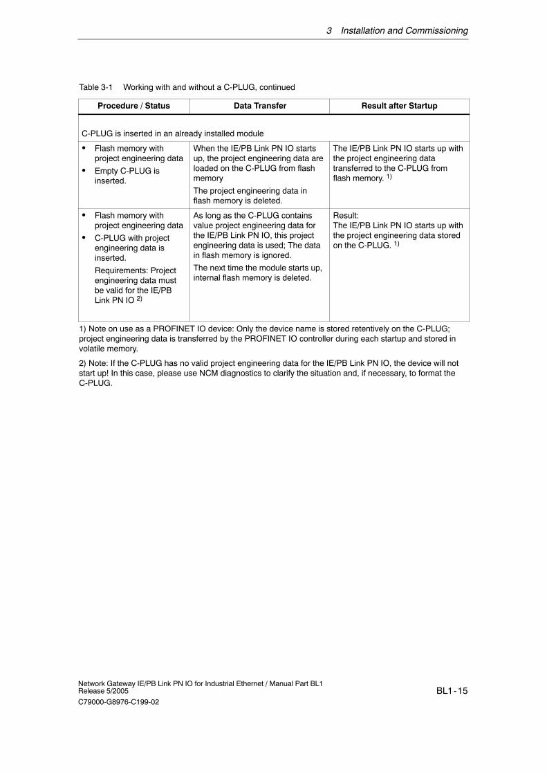
Table 3-1 Working with and without a C-PLUG, continued
Procedure / Status Result after StartupData Transfer
C-PLUG is inserted in an already installed module
� Flash memory withproject engineering data
� Empty C-PLUG isinserted.
When the IE/PB Link PN IO startsup, the project engineering data areloaded on the C-PLUG from flashmemory
The project engineering data inflash memory is deleted.
The IE/PB Link PN IO starts up withthe project engineering datatransferred to the C-PLUG fromflash memory. 1)
� Flash memory withproject engineering data
� C-PLUG with projectengineering data isinserted.
Requirements: Projectengineering data mustbe valid for the IE/PB
)
As long as the C-PLUG containsvalue project engineering data forthe IE/PB Link PN IO, this projectengineering data is used; The datain flash memory is ignored.
The next time the module starts up,internal flash memory is deleted.
Result:The IE/PB Link PN IO starts up withthe project engineering data storedon the C-PLUG. 1)
be valid for the IE/PBLink PN IO 2)
1) Note on use as a PROFINET IO device: Only the device name is stored retentively on the C-PLUG;project engineering data is transferred by the PROFINET IO controller during each startup and stored involatile memory.
2) Note: If the C-PLUG has no valid project engineering data for the IE/PB Link PN IO, the device will notstart up! In this case, please use NCM diagnostics to clarify the situation and, if necessary, to format theC-PLUG.
4 Project Engineering with STEP 7
BL1-16Network Gateway IE/PB Link PN IO for Industrial Ethernet / Manual Part BL1
Release 5/2005
C79000-G8976-C199-02
4 Project Engineering with STEP 7
To connect (initial addressing) and configure the IE/PB Link PN IO, you require theSTEP 7 configuration software (see Chapter 1).
NCM S7 is integrated in STEP 7; with NCM S7, you also have direct access toNCM diagnostics over the start menu and the firmware loader (see section 6.2).
Depending on the area of application of the IE/PB Link PN IO, project engineeringinvolves the following steps:
� Use as a PROFINET IO device and as gateway
- Assigning the device name for the first time
- Configuring IE/PB Link PN IO a a PROFINet IO device withSTEP 7/HW Config; here, a DP master system is assigned to theIE/PB Link PN IO. The configuration data is loaded automatically from thePROFINET IO controller.
� Use as a gateway only
- Initial Address Assignment
- Configuring the IE/PB Link PN IO as an S7-300 station withSTEP 7/HW Config and downloading the configuration data to theIE/PB Link PN IO.
Notice
You must always “Reset to factory settings” if you want to change the mode of theIE/PB Link PN IO that is already set.
4.1 Use as a PROFINET IO Device and as Gateway
Configuring Properties and Addresses with STEP 7
To provide the IE/PB Link PN IO with address information and further parameters,you must create a loadable database (configuration) in STEP 7.
How to...
...to configure the IE/PB Link PN IO as PROFINET IO device withSTEP 7/HW Config:
1. Start with an existing STEP 7 project in which you have already created aPROFINET IO controller, for example an S7-400 station with a CP 443-1Advanced.
2. Double-click the station you have created to open the hardware configuration
4 Project Engineering with STEP 7
BL1-17Network Gateway IE/PB Link PN IO for Industrial Ethernet / Manual Part BL1Release 5/2005
C79000-G8976-C199-02
tool HW Config.
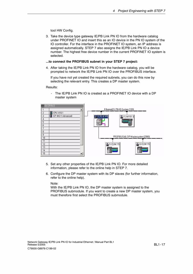
3. Take the device type gateway IE/PB Link PN IO from the hardware catalogunder PROFINET IO and insert this as an IO device in the PN IO system of theIO controller. For the interface in the PROFINET IO system, an IP address isassigned automatically. STEP 7 also assigns the IE/PB Link PN IO a devicenumber. The highest free device number in the current PROFINET IO system isselected.
...to connect the PROFIBUS subnet in your STEP 7 project:
4. After taking the IE/PB Link PN IO from the hardware catalog, you will beprompted to network the IE/PB Link PN IO over the PROFIBUS interface.
If you have not yet created the required subnets, you can do this now byselecting the relevant entry. This creates a DP master system.
Results:
- The IE/PB Link PN IO is created as a PROFINET IO device with a DPmaster system
5. Set any other properties of the IE/PB Link PN IO. For more detailedinformation, please refer to the online help in STEP 7.
6. Configure the DP master system with its DP slaves (for further information,refer to the online help).
Note:With the IE/PB Link PN IO, the DP master system is assigned to thePROFIBUS submodule. If you want to create a new DP master system, youmust therefore first select the PROFIBUS submodule.
4 Project Engineering with STEP 7
BL1-18Network Gateway IE/PB Link PN IO for Industrial Ethernet / Manual Part BL1
Release 5/2005
C79000-G8976-C199-02
How to Commission the IE/PB Link PN IO as a PROFINET IO Device
7. Assign a device name to the IE/PB Link PN IO for the first time.
The IE/PB Link PN IO ships with a factory-set MAC address. Without furtherconfiguration, the device can only be accessed over the Ethernet port using thisMAC address.
During configuration, an IP address is assigned automatically. This IP addressis transferred to the IE/PB Link PN IO (IO device) later when the PROFINET IOcontroller starts up.
To allow the IO controller to identify the IO device at this time, you must firstassign a device name to the IE/PB Link PN IO just like any other IO device(refer to the flowchart on page BL1-10). To do this, use the menu commandPLC � Ethernet � Assign Device Name... in the SIMATIC Manager or in HWConfig.
(You will find more detailed information on this procedure in the STEP 7 onlinehelp.)
8. Download the configuration of the appropriate PROFINET IO controller. The IOcontroller receives the configuration data of the IE/PB Link PN IO. When the IOcontroller starts up, the IE/PB Link PN IO is configured automatically just likeother PROFINET IO devices.
Note
The configuration data loaded from the PROFINET IO controller is not storedretentively by the IE/PB Link PN IO. After turning the power for the device off andon again, all the configuration data except for the device name is deleted. Duringstartup, the configuration data is loaded again by the PROFINET IO controller.
4 Project Engineering with STEP 7
BL1-19Network Gateway IE/PB Link PN IO for Industrial Ethernet / Manual Part BL1Release 5/2005
C79000-G8976-C199-02
4.2 Use As a Gateway Only
4.2.1 Configuring and Commissioning
How to...
...configure the IE/PB Link PN IO as an S7-300 station withSTEP 7/HW Config:
1. Open an existing STEP 7 project or create a new project.
2. Create a SIMATIC 300 station.
3. Double-click the station you have created to open the hardware configurationtool HW Config.
4. Take the gateway IE/PB Link PN IO device type from the SIMATIC 300hardware catalog.
4 Project Engineering with STEP 7
BL1-20Network Gateway IE/PB Link PN IO for Industrial Ethernet / Manual Part BL1
Release 5/2005
C79000-G8976-C199-02
...connect the IE/PB Link PN IO to the Ethernet and PROFIBUS subnet inyour STEP 7 project:
5. After taking the IE/PB Link PN IO from the hardware catalog, you will beprompted to network the IE/PB Link PN IO over the Ethernet interface and thenover the PROFIBUS interface.
If you have not yet created the required subnets, you can do this now byselecting the relevant entry.
Note
The IE/PB Link can also be used as a gateway between an MPI subnet and anEthernet subnet. To do this, the PROFIBUS interface of the IE/PB Link must benetworked with the MPI subnet (see 5.)
Result: You have created the IE/PB Link PN IO component with a basic moduleand the Ethernet and PROFIBUS submodules in the S7-300 station in HW Config.
6. When necessary, set other properties of the IE/PB Link PN IO; for moredetailed information, refer to the following sections 4.2.2 through 4.2.4.
How to Commission the IE/PB Link PN IO
7. Assign an IP address to the IE/PB Link PN IO if you have not already done soin the SIMATIC Manager without the configuration steps described here. In HWConfig, select the menu command � PLC � Assign Ethernet EthernetAddress...
Note
You will find more detailed information on this procedure in the STEP 7 onlinehelp. Note the requirements outlined there.
8. Download the database (configuration) from STEP 7 to the IE/PB Link PN IO.
When you download for the first time, you must download over IndustrialEthernet using the TCP/IP interface. Depending on the PG network attachment,subsequent downloads are then possible over PROFIBUS or over IndustrialEthernet using the TCP/IP interface.
Notice
Please note that the IE/PB Link PN IO is a special configuration componentcontaining all the necessary station components. This means that you cannotplace any other components such as a DIN rail or modules alongside the IE/PBLink PN IO in the S7-300 station you have created!
4 Project Engineering with STEP 7
BL1-21Network Gateway IE/PB Link PN IO for Industrial Ethernet / Manual Part BL1Release 5/2005
C79000-G8976-C199-02
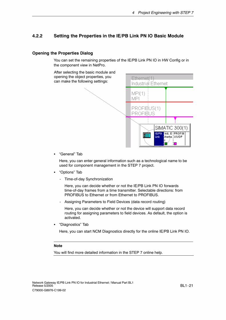
4.2.2 Setting the Properties in the IE/PB Link PN IO Basic Module
Opening the Properties Dialog
You can set the remaining properties of the IE/PB Link PN IO in HW Config or inthe component view in NetPro.
After selecting the basic module andopening the object properties, youcan make the following settings:
� “General” Tab
Here, you can enter general information such as a technological name to beused for component management in the STEP 7 project.
� “Options” Tab
- Time-of-day Synchronization
Here, you can decide whether or not the IE/PB Link PN IO forwardstime-of-day frames from a time transmitter. Selectable directions: fromPROFIBUS to Ethernet or from Ethernet to PROFIBUS.
- Assigning Parameters to Field Devices (data record routing)
Here, you can decide whether or not the device will support data recordrouting for assigning parameters to field devices. As default, the option isactivated.
� “Diagnostics” Tab
Here, you can start NCM Diagnostics directly for the online IE/PB Link PN IO.
Note
You will find more detailed information in the STEP 7 online help.
4 Project Engineering with STEP 7
BL1-22Network Gateway IE/PB Link PN IO for Industrial Ethernet / Manual Part BL1
Release 5/2005
C79000-G8976-C199-02
4.2.3 Setting Properties in the Ethernet Submodule
In NetPro, the S7-300 station you haveconfigured is displayed as shown here:
In HW Config, the S7-300 station youhave configured is displayed as shownbelow:
After you have selected the Ethernetsubmodule and opened the objectproperties, you can make thesettings described here:
These properties can be configured:
� “General” Tab
Here, you can enter general information to be used for component managementin the STEP 7 project. You can also set parameters for the interface to Ind.Ethernet.
� “Options” Tab
Here, you can make any individual network settings that may be necessary; asdefault, automatic setting is selected here.
4 Project Engineering with STEP 7
BL1-23Network Gateway IE/PB Link PN IO for Industrial Ethernet / Manual Part BL1Release 5/2005
C79000-G8976-C199-02
� “Addressing” Tab
In the ”Addressing” tab, you can assign the previously configured IP addressand the IP parameters to the IE/PB Link PN IO once; these are simplydisplayed here and cannot be modified.
Only after these steps are completed, can you download the configuration datato the IE/PB Link PN IO from the PG/PC over Ethernet or PROFIBUS.
Note
You will find more detailed information on this procedure in the STEP 7 onlinehelp.
4.2.4 Setting the Properties in the PROFIBUS Submodule
After selecting the PROFIBUS/DPsubmodule and opening the objectproperties, you can make thefollowing settings:
� “General” Tab
Here, you can set the parameters for the interface to PROFIBUS; in otherwords, assign the network and the PROFIBUS address.
You can also enter general information to be used in component managementin the STEP 7 project.
� “Addresses” Tab
The address parameter for diagnostics displayed here has no significance forthe IE/PB Link PN IO.
5 Operation - Controls and Displays
BL1-24Network Gateway IE/PB Link PN IO for Industrial Ethernet / Manual Part BL1
Release 5/2005
C79000-G8976-C199-02
5 Operation - Controls and Displays
5.1 Controlling the Operating Mode
There are different ways in which you can control the mode of the IE/PB Link, asfollows:
� Mode selector
� SIMATIC Manager in STEP 7
To control the mode from STEP 7 / NCM S7 Diagnostics, the mode selector mustbe set to RUN.
Mode Selector
With the mode selector, you can set the following modes:
� Switch from STOP to RUN:
The IE/PB Link reads the configured and/or modified data into the work memoryand then changes to the RUN mode.
Note
The modes can only be controlled using NCM S7 or the SIMATIC Manager whenthe selector is set to RUN.
� Switch from RUN to STOP:
The IE/PB Link changes to the STOP mode and behaves as follows:
- PROFIBUS DP changes to the safe state;
- PG/OP access to DP slaves and other PROFIBUS stations remain possible.
5 Operation - Controls and Displays
BL1-25Network Gateway IE/PB Link PN IO for Industrial Ethernet / Manual Part BL1Release 5/2005
C79000-G8976-C199-02
5.2 LED Displays
Along with the six LEDs on the front panel that are used to indicate the mode, anadditional display with three LEDs is located beside the RJ-45 jack (hidden by thefront panel) and indicates the communication status.
LEDs Displaying the Status
The different combinations of the LEDs on the front panel indicate the status:
SF System error
BF DP PROFIBUS DP bus errorRX/TX Send / receive activity on Ind. EthernetRUN Normal operationSTOP Operation in STOP mode
BF PN PROFINET bus error
Table 5-1
SF(red)
BF PN (red)
BF DP(red)
RX/TX(green)
1)
RUN(green)
STOP(yellow)
Operating Mode
Turn on (lamp test)
Configuration distribution phase
Starting up (STOP->RUN)
Running (RUN)
Stopping (RUN->STOP)
Stopped (STOP)
Running (RUN), no error
Running (RUN), error of a DP slave
Running (RUN), error on PROFIBUSthat does not affect PROFINET IO.
Running (RUN), with error
� Error on PROFIBUS that affectsPROFINET IO (for example, IOdevice)
or
� Error on PROFINET IO that alsoaffects PROFIBUS (for exampleproxy not started up)
5 Operation - Controls and Displays
BL1-26Network Gateway IE/PB Link PN IO for Industrial Ethernet / Manual Part BL1
Release 5/2005
C79000-G8976-C199-02
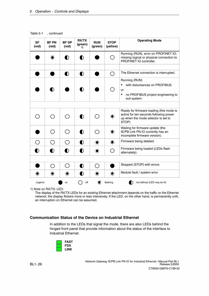
Table 5-1 , continued
SF(red)
Operating ModeSTOP
(yellow)RUN
(green)
RX/TX(green)
1)
BF DP(red)
BF PN (red)
Running (RUN), error on PROFINET IO;missing logical or physical connection toPROFINET IO controller.
The Ethernet connection is interrupted.
Running (RUN)
� with disturbances on PROFIBUS
or
� no PROFIBUS project engineering tosuit system.
Ready for firmware loading (this mode isactive for ten seconds following powerup when the mode selector is set toSTOP)
Waiting for firmware update (theIE/PB Link PN IO currently has anincomplete firmware version).
Firmware being deleted.
Firmware being loaded (LEDs flashalternately).
Stopped (STOP) with errors
Module fault / system error
Legend: on off flashing not defined (LED may be lit)
1) Note on RX/TX-LED:The display of the RX/TX LEDs for an existing Ethernet attachment depends on the traffic on the Ethernetnetwork; the display flickers more or less intensively. If the LED, on the other hand, is permanently unlit,an interruption on Ethernet can be assumed.
Communication Status of the Device on Industrial Ethernet
In addition to the LEDs that signal the mode, there are also LEDs behind thehinged front panel that provide information about the status of the interface toIndustrial Ethernet.
FASTFDXLINK
5 Operation - Controls and Displays
BL1-27Network Gateway IE/PB Link PN IO for Industrial Ethernet / Manual Part BL1Release 5/2005
C79000-G8976-C199-02
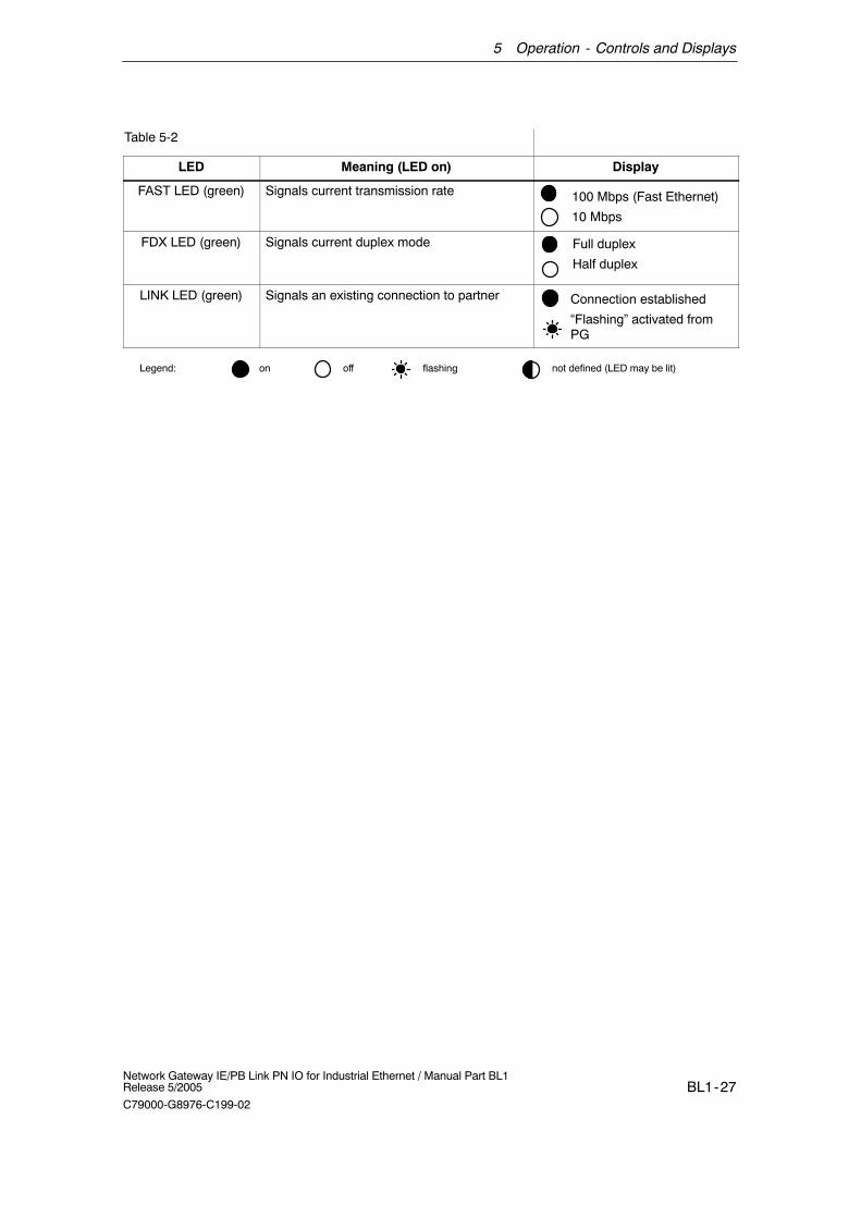
Table 5-2
LED Meaning (LED on) Display
FAST LED (green) Signals current transmission rate 100 Mbps (Fast Ethernet)
10 Mbps
FDX LED (green) Signals current duplex mode Full duplex
Half duplex
LINK LED (green) Signals an existing connection to partner Connection established
“Flashing” activated fromPG
Legend: on off flashing not defined (LED may be lit)
6 Further Notes on Operation
BL1-28Network Gateway IE/PB Link PN IO for Industrial Ethernet / Manual Part BL1
Release 5/2005
C79000-G8976-C199-02
6 Further Notes on Operation
6.1 Memory Reset / Resetting to the Factory Settings
For the IE/PB Link PN IO, two memory reset variants are available:
� Clear / reset
� Resetting to factory settings
Notice
You must always “reset to factory settings” if you want to change the configuredmode of operation of the IE/PB Link PN IO; you can operate the module as aPROFINET IO device or only as a gateway.
How to Use the Functions
You can start the memory reset functions in STEP 7. The device must be in STOP.
� Clear / reset
In STEP 7/HW Config with PLC � Clear/Reset
or
In STEP 7 / NCM Diagnostics with Operating Mode � Clear/Reset Module
� Resetting to factory settings
In STEP 7 / NCM Diagnostics with Operating Mode � Reset to FactoryDefaults
Memory Reset - Effects
After clear/reset, the IE/PB Link PN IO retains the retentive parameters.
6 Further Notes on Operation
BL1-29Network Gateway IE/PB Link PN IO for Industrial Ethernet / Manual Part BL1Release 5/2005
C79000-G8976-C199-02
Resetting to Factory Settings - Effects
After it has been reset to the factory settings, the IE/PB Link PN IO still has theMAC address that was set in the factory (as shipped).
The content of the C-PLUG is completely deleted. The next time the module startsup, the C-PLUG is initialized as a data record of the type IE/PB Link PN IO.
6.2 Loadable Firmware
The IE/PB Link PN IO supports the updating of firmware with the Firmware Loader.
An update of the firmware can be downloaded from the PC/programming device atany time.
The IE/PB Link PN IO remains in the firmware load mode for ten seconds afterturning on the power with the mode selector set to STOP; the LEDs indicate thisstatus (see Section 5.2 ).
Note
Please note that the port of the PG must be set to ISO and the PG must be in thesame subnet!
After downloading the firmware, the device must be started again.
For more information on downloading the firmware, refer to the README file of theNCM S7 for Industrial Ethernet / PROFIBUS configuration software.
6.3 Working with Fast Ethernet - Automatic Switchover
The IE/PB Link PN IO has a 10/100 Mbps half/full duplex port with“Autonegotiation” for automatic switchover.
You will find more information about the current mode in NCM diagnostics in thediagnostic object “Industrial Ethernet” in the Section “Network Attachment”.
6.4 Changing Interface Parameters when Downloading
If you change the interface parameters (for example the transmission rate)compared with current settings, the download may abort.
In this case, adapt the PG/PC interface to the network configuration according tothe new interface parameters and then start the complete download again.
6 Further Notes on Operation
BL1-30Network Gateway IE/PB Link PN IO for Industrial Ethernet / Manual Part BL1
Release 5/2005
C79000-G8976-C199-02
6.5 Forwarding the Time of Day
If time forwarding is disabled on the IE/PB Link PN IO, a device with firmwareversion V1.0 works with an internal time of day even if there is a time master onthe Ethernet network.
As of firmware version V2.0, the time of day for the time stamp of the diagnosticbuffer is taken from the time master even when time forwarding is disabled.
6.6 SNMP Agent
SNMP (Simple Network Management Protocol)
The IE/PB Link PN IO supports data queries over SNMP in version 1.
SNMP is a protocol language for managing networks and is easy to handle. Totransmit data, SNMP uses the connectionless UDP protocol.
The information on the properties of SNMP-compliant devices is entered in MIBfiles (MIB = Managed Information Base). For more detailed information on workingwith MIB files, refer to the documentation of the SNMP client you are using(example of an SNMP client: SNMP OPC Server from SIMATIC NET).
Supported MIB Objects
The IE/PB Link PN IO supports all MIB objects according to the MIB standard MIBII (RFC 1213).
Exceptions / Restrictions:
� Write access is permitted only for the following MIB objects:
sysContact, sysLocation and sysName;
For security reasons, only read access is permitted for all other MIB objects.
� Traps are not supported by the IE/PB Link PN IO.
Access Permissions using Community Name
The IE/PB Link PN IO uses the following community names for assigning rights:
� For read access: “public”
� for read and write access: “private”
(note the use of lowercase letters!)
7 Performance Data
BL1-31Network Gateway IE/PB Link PN IO for Industrial Ethernet / Manual Part BL1Release 5/2005
C79000-G8976-C199-02
7 Performance Data
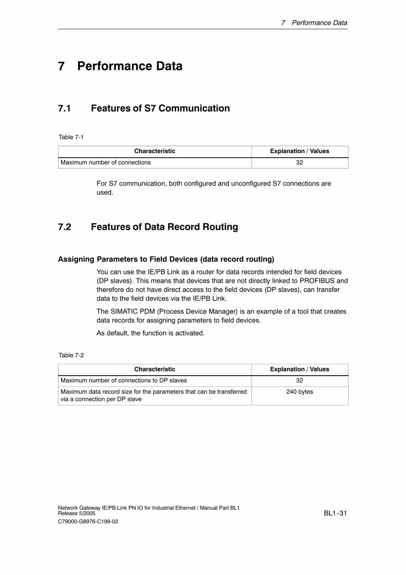
7.1 Features of S7 Communication
Table 7-1
Characteristic Explanation / Values
Maximum number of connections 32
For S7 communication, both configured and unconfigured S7 connections areused.
7.2 Features of Data Record Routing
Assigning Parameters to Field Devices (data record routing)
You can use the IE/PB Link as a router for data records intended for field devices(DP slaves). This means that devices that are not directly linked to PROFIBUS andtherefore do not have direct access to the field devices (DP slaves), can transferdata to the field devices via the IE/PB Link.
The SIMATIC PDM (Process Device Manager) is an example of a tool that createsdata records for assigning parameters to field devices.
As default, the function is activated.
Table 7-2
Characteristic Explanation / Values
Maximum number of connections to DP slaves 32
Maximum data record size for the parameters that can be transferredvia a connection per DP slave
240 bytes
7 Performance Data
BL1-32Network Gateway IE/PB Link PN IO for Industrial Ethernet / Manual Part BL1
Release 5/2005
C79000-G8976-C199-02
7.3 Total Number of Connections
You can use a total of maximum 48 connections (S7 connections and connectionsto the DP slaves).
Notice
Please note that one TCP/IP connection on Industrial Ethernet is occupied per S7connection used.
7.4 Characteristic Data for PROFINET IO
Table 7-3
Characteristic Explanation / Values
Maximum number of DP slaves on IE/PB LInk PN IO (PROFINET IOdevices for PROFINET IO)
64
Maximum number of DP inputs 2048 bytes
Maximum number of DP outputs 2048 bytes
Note
All PROFINET IO devices (DP slaves) to be connected to the IE/PB Link must becreated with STEP 7 as PROFIBUS-DPV0 (standard slaves).
7 Performance Data
BL1-33Network Gateway IE/PB Link PN IO for Industrial Ethernet / Manual Part BL1Release 5/2005
C79000-G8976-C199-02
7.5 Update Time when Operating PROFINET IO Alongsideother Services
Depending on the number of PROFINET IO devices operating on the sameEthernet subnet, STEP 7 automatically sets the lowest possible value for theupdate time for the IO devices. If required, you can configure this update time forthe IO devices using the properties dialog of the PROFINET IO system inHW Config (see Section 4.1).
It is advisable to configure a higher update time in the following situations:
� When non-cyclic communication services such as S7 connections, data recordrouting or HMI connections are used at the same time as cyclic communicationover PROFINET IO;
� When diagnostic or alarm frames occur often in the DP master system.
Recommendation: Do not set the lowest possible update time when operatingmultiple services. Select the next higher value proposed by STEP 7.
8 Compatibility with Previous Products
BL1-34Network Gateway IE/PB Link PN IO for Industrial Ethernet / Manual Part BL1
Release 5/2005
C79000-G8976-C199-02
8 Compatibility with Previous Products
8.1 Range of Functions of the Firmware Versions:
Table 8-1
Firmware Version Range of Functions
V 1.0 � Gateway as PROFINET IO proxy and in standard mode
� Routing
� Data record gateway
� DP slaves complying with PROFIBUS DP-V0 standard
V2.0 � Gateway as PROFINET IO proxy and in standard mode
� Routing
� Data record gateway
� MPI networking
� DP slaves complying with PROFIBUS DP-V0 and DP-V1standard and Siemens DP slaves
� Direct data exchange (slave-to-slave)
8.2 Upgrading Older Modules / Use as Replacement
Upgrading:
Modules with a firmware version V1.0 can be upgraded to firmware version V2.0(loadable firmware). This allows the full range of functions of V2.0 to be used.
8 Compatibility with Previous Products
BL1-35Network Gateway IE/PB Link PN IO for Industrial Ethernet / Manual Part BL1Release 5/2005
C79000-G8976-C199-02
Use as a Replacement:
Table 8-2
Previously used Module Steps in Configuration
6GK1 411-5AB00 with firmware version V1.0
Case a: Configuration unchanged (replacement)
If you do not require any extended functionality compared with thepreviously used device, you do not need to make any changes to theconfiguration.
To put the module into operation, you simply need to replace the olddevice with the power supply turned off.
Case b: Expanded configuration (using new functions)
If you want to use options that go beyond those that were possiblewith the IE/PB Link PN IO you have been using up to now, follow thesteps below:
� Replace the IE/PB Link PN IO V1.0 that you configuredpreviously in STEP 7 / HW Config with V2.0; you will find this inthe hardware catalog (refer to the section on configuration).
� Expand your configuration according to your requirements, forexample with DP-V1 slaves on the master chain.
� Save, compile and download the configuration data again to thestation with the PROFINET IO controller or to the IE/PB Link PNIO.
9 Technical Specifications
BL1-36Network Gateway IE/PB Link PN IO for Industrial Ethernet / Manual Part BL1
Maximum current consumption onthe PROFIBUS interface withnetwork components connected (e.g.optical network components)
100 mA at 5V
Interfaces
Attachment to Industrial Ethernet:
Attachment to PROFIBUS
RJ-45 jack
9-pin sub-D female connector
Power supply DC +24 V (permitted range: 20.4 V to 28.8 V)
Current consumption
� from external 24 V DC Approx. 0.29 A (typical at 24 V)
Power loss 7.5 W
Permitted ambient conditions
� Operating temperature
� Transportation/storage temperature
� Relative humidity max.
� Altitude
0 °C to +60 °C installed horizontally0 °C to +40 °C installed vertically
-40 °C to +70 °C95% at +25 °Cup to 2000 m above sea level
Design
� Module format
� Dimensions (W x H x D) in mm
� Weight approx.
Compact module S7-300; double width
80 x 125 x 120
600 g
In addition to this, all the information in /1/ S7-300 Module Data: ReferenceManual in the section ”General Technical Specification” on the topics listed belowapplies to the IE/PB Link
� Electromagnetic compatibility
� Transportation and storage conditions
� Mechanical and climatic ambient conditions
� Insulation tests, class of protection and degree of protection