s Preface, Contents Introducing the Product and Installing the Software 1 Basics of Designing a Program 2 Startup and Operation 3 Setting Up and Editing the Project 4 Configuring the Hardware 5 Programming Blocks 6 Establishing an Online Connection and Making CPU Settings 7 Import, Export, Save As 8 Downloading to the CPU and Uploading to the PG 9 Debugging 10 Diagnostics 11 Printing Project Documentation 12 Tips and Tricks 13 Appendix A Index SIMATIC Programming with STEP 7 Lite V3.0 Manual Edition 04/2004 A5E00293884-01
Transcript
s
Preface, Contents
Introducing the Product and Installing the Software 1 Basics of Designing a Program 2 Startup and Operation 3 Setting Up and Editing the Project 4 Configuring the Hardware 5 Programming Blocks 6 Establishing an Online Connection and Making CPU Settings
7
Import, Export, Save As 8 Downloading to the CPU and Uploading to the PG 9 Debugging 10 Diagnostics 11 Printing Project Documentation 12 Tips and Tricks 13 Appendix A Index
The reproduction, transmission or use of this document or its contents is not permitted without express written authority. Offenders will be liable for damages. All rights, including rights created by patent grant or registration of a utility model or design, are reserved. Siemens AG Bereich Automation and Drives Geschaeftsgebiet Industrial Automation Systems Postfach 4848, D- 90327 Nuernberg
This manual contains notices intended to ensure personal safety, as well as to protect the products and
connected equipment against damage. These notices are highlighted by the symbols shown below and
graded according to severity by the following texts:
! Danger indicates that death, severe personal injury or substantial property damage will result if proper precautions are not taken.
! Warning indicates that death, severe personal injury or substantial property damage can result if proper precautions are not taken.
! Caution indicates that minor personal injury can result if proper precautions are not taken.
Caution
indicates that property damage can result if proper precautions are not taken.
Notice
draws your attention to particularly important information on the product, handling the product, or to a particular part of the documentation.
Qualified Personnel
Only qualified personnel should be allowed to install and work on this equipment. Qualified persons
are defined as persons who are authorized to commission, to ground and to tag circuits, equipment, and
systems in accordance with established safety practices and standards.
Correct Usage
Note the following:
! Warning This device and its components may only be used for the applications described in the catalog or the
technical description, and only in connection with devices or components from other manufacturers
which have been approved or recommended by Siemens.
This product can only function correctly and safely if it is transported, stored, set up, and installed correctly, and operated and maintained as recommended.
Trademarks
SIMATIC®, SIMATIC HMI® and SIMATIC NET® are registered trademarks of SIEMENS AG.
Third parties using for their own purposes any other names in this document which refer to trademarks
might infringe upon the rights of the trademark owners.
Programming with STEP 7 Lite V3.0 A5E00293884-01 iii
Preface
Purpose This manual provides a complete overview of programming with STEP 7 Lite. It is designed to support you when installing and commissioning the software. It explains how to proceed when creating and structuring user programs and describes the language elements.
The manual is intended for people who are involved in carrying out control tasks using STEP 7 Lite and SIMATIC automation systems.
We recommend that you familiarize yourself with the examples in the manual "First Steps with STEP 7 Lite." It provides an easy introduction to "Programming with STEP 7 Lite."
Basic Knowledge Required
In order to understand this manual, general knowledge of automation technology is required.
In addition, you must be familiar with using computers or PC-similar tools (for example, programming devices) with the MS Windows 2000 Professional, MS Windows XP Home and MS Windows XP Professional operating systems.
Scope of the Manual
This manual is valid for release 3.0 of the STEP 7 Lite programming software package.
Preface
Programming with STEP 7 Lite V3.0 iv A5E00293884-01
STEP 7 Lite Documentation Packages
This manual is part of the software package STEP 7 Lite.
The following table displays an overview of the STEP 7 Lite documentation:
Documentation Purpose Order Number
Programming with STEP 7 Lite
Provides background information for realizing control tasks with STEP 7 Lite.
Part of the software package STEP 7 Lite
First Steps with STEP 7 Lite
Describes the most important procedures using practical excercises.
Part of the software package STEP 7 Lite
Online Help Purpose Order Number
Help on STEP 7 Lite Provides background information for realizing control tasks with STEP 7 Lite.
Part of the software package STEP 7 Lite
Reference helps on STL/LAD/FBD
Reference helps on block libraries
Context-sensitive reference information.
Part of the software package STEP 7 Lite
ToolTips and direct help
Offers information on the current context, for example, on menu commands, elements of the user interface and dialog boxes
Part of the software package STEP 7 Lite
Documentation Reply Form
If you have comments about this manual or the online help, please fill out the questionnaire at the end of this manual and send it the address shown. Please take the time to add your own evaluation grade.
http://www.ad.siemens.de/partner
You will find a guide to the technical documentation offered for the individual SIMATIC Products and Systems here at:
http://www.siemens.com/simatic-tech-doku-portal
Training Centers
Siemens offers a number of training courses to familiarize you with the SIMATIC S7 automation system. Please contact your regional training center or our central training center in D 90327 Nuremberg, Germany for details: Telephone: +49 (911) 895-3200.
Programming with STEP 7 Lite V3.0 A5E00293884-01 vii
Contents
1 Introducing the Product and Installing the Software 1-1
1.1 Overview STEP 7 Lite .......................................................................................1-1 1.2 Project Window and Views in STEP 7 Lite .......................................................1-5 1.3 Help and Documentation on STEP 7 Lite .........................................................1-9 1.4 Installation .........................................................................................................1-9 1.4.1 Automation License Manager ...........................................................................1-9 1.4.1.1 User Rights Through the Automation License Manager...................................1-9 1.4.1.2 Installing the Automation License Manager ....................................................1-11 1.4.1.3 Guidelines for Handling License Keys ............................................................1-12 1.4.2 Installing STEP 7 Lite......................................................................................1-13 1.4.2.1 Installation Procedure .....................................................................................1-14 1.4.2.2 Setting the PG/PC Interface............................................................................1-16 1.4.3 Uninstalling STEP 7 Lite .................................................................................1-17
2 Basics of Designing a Program 2-1
2.1 Programs in a CPU ...........................................................................................2-1 2.2 Blocks in the User Program ..............................................................................2-2 2.2.1 Organization Blocks and Program Structure.....................................................2-3 2.2.2 Call Hierarchy in the User Program ..................................................................2-8 2.2.3 Cyclic Program Processing and CPU Settings ...............................................2-10 2.2.3.1 Organization Block for Cyclic Program Processing (OB1)..............................2-10 2.2.3.2 Communication Load ......................................................................................2-12 2.2.4 Interrupt-Driven Program Processing .............................................................2-14 2.2.4.1 Organization Blocks for Interrupt-Driven Program Processing .......................2-14 2.2.4.2 Time-of-Day Interrupt Organization Blocks (OB10 to OB17)..........................2-15 2.2.4.3 Delay Interrupt Organization Blocks (OB20 to OB23) ....................................2-17 2.2.4.4 Cyclic Interrupt Organization Blocks (OB30 to OB38) ....................................2-18 2.2.4.5 Hardware Interrupt Organization Blocks (OB40 to OB47) ..............................2-20 2.2.4.6 Startup Organization Blocks (OB100 / OB102)...............................................2-21 2.2.4.7 Background Organization Block (OB90) .........................................................2-23 2.2.4.8 Error Handling Organization Blocks (OB80 to OB87 / OB121 to OB122) ......2-24 2.2.5 Block Types for Structured Programming .......................................................2-26 2.2.5.1 Functions (FC) ................................................................................................2-26 2.2.5.2 Function Blocks (FB).......................................................................................2-26 2.2.5.3 Instance Data Blocks ......................................................................................2-29 2.2.6 Shared Data Blocks (DB) ................................................................................2-31 2.2.6.1 System Function Blocks (SFB) and System Functions (SFC)........................2-32
Contents
Programming with STEP 7 Lite V3.0 viii A5E00293884-01
3 Startup and Operation 3-1
3.1 Starting STEP 7 Lite..........................................................................................3-1 3.2 Calling the Help Functions ................................................................................3-2 3.3 User Interface and Operation............................................................................3-3 3.3.1 Structure of the User Interface..........................................................................3-3 3.3.2 Symbols in the Project Window ........................................................................3-5 3.3.3 Elements in Windows and Dialog Boxes ..........................................................3-6 3.3.4 Session Memory ...............................................................................................3-9 3.3.5 Changing the Window Arrangement .................................................................3-9 3.3.6 Saving and Restoring the Window Layout ........................................................3-9 3.3.7 Finding and Replacing Terms .........................................................................3-10 3.3.8 How to Manage Objects..................................................................................3-12 3.3.8.1 Renaming Objects...........................................................................................3-12 3.3.8.2 Moving Objects ...............................................................................................3-12 3.3.8.3 Deleting Objects..............................................................................................3-12 3.4 Keyboard Control ............................................................................................3-13 3.4.1 Shortcut Keys for Menu Commands ...............................................................3-13 3.4.2 Key Combinations for Moving the Cursor .......................................................3-15 3.4.3 Shortcut Keys for Marking Text.......................................................................3-17 3.4.4 Shortcut Keys for Access to the Online Help ..................................................3-17 3.4.5 Shortcut Keys for Switching Windows ............................................................3-17 3.5 Using TeleService ...........................................................................................3-18
4 Setting Up and Editing the Project 4-1
4.1 What is a STEP 7 Lite Project...........................................................................4-1 4.2 Setting Up a Project ..........................................................................................4-4 4.2.1 Creating a Project .............................................................................................4-4 4.2.2 Inserting a Program...........................................................................................4-4 4.3 Editing a Project ................................................................................................4-6 4.3.1 Applying and Saving Changes..........................................................................4-6 4.3.2 How to Edit Projects..........................................................................................4-8 4.3.2.1 Copying a Project..............................................................................................4-8 4.3.2.2 Copying Part of a Project ..................................................................................4-8 4.3.2.3 Configuring Hardware (General) .......................................................................4-8 4.3.2.4 Creating the Software in the Project (General) .................................................4-9 4.4 Deleting and Renaming a Project .....................................................................4-9
5 Configuring the Hardware 5-1
5.1 Basics of Configuring Hardware with STEP 7 Lite............................................5-1 5.1.1 Introduction to Configuring Hardware ...............................................................5-1 5.1.2 Basic Procedure for Configuring Hardware ......................................................5-2 5.1.2.1 Basic Steps for Configuring a Station ...............................................................5-3 5.1.2.2 Layout of the 'Hardware Configuration' View....................................................5-4 5.1.2.3 Configuration Table as a Representation of a Rack .........................................5-5 5.1.2.4 Setting the Properties of Components ..............................................................5-5 5.1.2.5 What You Should Know About Slot Rules and Other Rules.............................5-6 5.2 Configuring Modules .........................................................................................5-7 5.2.1 Rules for Arranging Modules (SIMATIC 300) ...................................................5-7 5.2.1.1 Special Rules for the Dummy Module (DM 370 Dummy) .................................5-8 5.2.1.2 Special Rules for the Digital Simulation Module (SIM 374 IN/OUT 16) ...........5-8 5.2.2 Rules for Arranging Modules (ET 200S and ET 200X).....................................5-9 5.2.2.1 Rules for Arranging Modules with ET 200S ......................................................5-9 5.2.2.2 Rules for Arranging Modules with ET 200X ......................................................5-9
Contents
Programming with STEP 7 Lite V3.0 A5E00293884-01 ix
5.2.3 How to Configure Modules..............................................................................5-10 5.2.3.1 Overview: Procedure for Configuring
and Assigning Parameters to a Station ..........................................................5-10 5.2.3.2 Selecting a Station Type .................................................................................5-10 5.2.3.3 Arranging Modules in a Rack..........................................................................5-11 5.2.3.4 Displaying the Version of the CPU Operating System in the Module List ......5-12 5.2.3.5 Arranging C7 Control Systems (Special Features) .........................................5-12 5.2.3.6 Assigning Properties to Modules/Interfaces....................................................5-13 5.2.3.7 Assigning Addresses.......................................................................................5-14 5.2.3.8 Assigning I/O Addresses.................................................................................5-14 5.2.3.9 Tips for Editing Station Configurations............................................................5-15 5.2.4 What You Should Know About ET 200S Motor Starters (High Feature) ........5-17 5.2.4.1 Detecting Plant Status Using Motor Current Values.......................................5-17 5.2.4.2 Blocking Current..............................................................................................5-17 5.2.4.3 Blocking Time..................................................................................................5-17 5.2.4.4 Response to No Current Detection .................................................................5-18 5.2.4.5 Asymmetry ......................................................................................................5-18 5.2.4.6 Thermal Motor Model ......................................................................................5-18 5.2.4.7 Recovery Time ................................................................................................5-18 5.2.4.8 Overview: Possible Motor Starter Actions.......................................................5-19 5.2.4.9 Motor Starter Assignments in the Process Image ..........................................5-20 5.3 Saving a Configuration and Consistency Check.............................................5-21
6 Programming Blocks 6-1
6.1 Defining Symbols ..............................................................................................6-1 6.1.1 Absolute and Symbolic Addressing ..................................................................6-1 6.1.2 Shared and Local Symbols ...............................................................................6-3 6.1.3 Displaying Shared or Local Symbols ................................................................6-4 6.1.4 Setting the Address Priority (absolute/symbolic) ..............................................6-4 6.1.5 Symbol Table for Shared Symbols ...................................................................6-6 6.1.5.1 Structure and Components of the Symbol Table ..............................................6-6 6.1.5.2 Addresses and Data Types Permitted in the Symbol Table .............................6-8 6.1.5.3 Incomplete and Ambiguous Symbols in the Symbol Table...............................6-9 6.1.6 Entering Shared Symbols ...............................................................................6-10 6.1.6.1 General Tips on Entering Symbols .................................................................6-11 6.1.6.2 Entering Single Shared Symbols in a Dialog Box...........................................6-12 6.1.6.3 Entering Multiple Shared Symbols in the Symbol Table.................................6-13 6.1.6.4 Exporting and Importing Symbol Tables .........................................................6-14 6.1.7 How to Edit the Symbol Table.........................................................................6-14 6.1.7.1 Opening a Symbol Table.................................................................................6-14 6.1.7.2 Defining Individual Symbols ............................................................................6-14 6.1.7.3 Inserting Symbol Rows ...................................................................................6-15 6.1.7.4 Deleting Symbol Rows ....................................................................................6-15 6.1.7.5 Filtering the Symbol Table ..............................................................................6-16 6.1.7.6 Unused Symbols .............................................................................................6-16 6.1.7.7 Addresses without a Symbol...........................................................................6-17 6.1.7.8 Sorting the Symbol Table................................................................................6-17 6.1.7.9 Selecting Symbol Rows ..................................................................................6-17 6.1.7.10 Copying Symbol Rows to the Clipboard .........................................................6-17 6.1.7.11 Saving a Symbol Table ...................................................................................6-17 6.1.8 How to Change the Window Settings .............................................................6-18 6.1.8.1 Toggling the Toolbar On/Off............................................................................6-18 6.1.8.2 Toggling the Status Bar On/Off .......................................................................6-18 6.1.8.3 Positioning the Toolbar ...................................................................................6-18 6.1.8.4 Setting the Size of a Window for Display ........................................................6-18
Contents
Programming with STEP 7 Lite V3.0 x A5E00293884-01
6.2 Working with Blocks ........................................................................................6-19 6.2.1 Block Editor .....................................................................................................6-19 6.2.2 Selecting the Programming Language............................................................6-20 6.2.2.1 Programming Languages of the Block Editor .................................................6-20 6.2.2.2 Ladder Logic Programming Language (LAD) .................................................6-21 6.2.2.3 Function Block Diagram Programming Language (FBD) ...............................6-22 6.2.2.4 Statement List Programming Language (STL) ...............................................6-22 6.2.3 Creating Blocks ...............................................................................................6-23 6.2.3.1 User-Defined Data Types (UDT).....................................................................6-23 6.2.3.2 Block Properties ..............................................................................................6-24 6.2.3.3 Setting Block Protection ..................................................................................6-26 6.2.3.4 Permitted Block Properties for Each Block Type ............................................6-27 6.2.3.5 Displaying Block Lengths ................................................................................6-27 6.2.3.6 Comparing Blocks ...........................................................................................6-28 6.2.4 Working with Libraries.....................................................................................6-29 6.2.4.1 Overview of Block Libraries.............................................................................6-29 6.3 Creating Logic Blocks .....................................................................................6-30 6.3.1 Basics of Creating Logic Blocks......................................................................6-30 6.3.1.1 Basic Procedure for Creating Logic Blocks.....................................................6-30 6.3.1.2 Default Settings for the LAD/STL/FBD Block Editor .......................................6-31 6.3.1.3 Instructions from the Command Libraries .......................................................6-31 6.3.1.4 Defining the Block Editor View........................................................................6-33 6.3.2 Editing the Variable Declaration Table............................................................6-35 6.3.2.1 Using the Variable Declaration in Logic Blocks ..............................................6-35 6.3.2.2 Relationship between the Variable Declaration Table
and the Statement Section .............................................................................6-36 6.3.2.3 Structure of the Variable Declaration Table ....................................................6-36 6.3.2.4 General Notes on Variable Declaration Tables...............................................6-38 6.3.2.5 How to Work with the Variable Declaration Table ..........................................6-39 6.3.3 Multiple Instances in the Variable Declaration Table......................................6-43 6.3.3.1 Using Multiple Instances .................................................................................6-43 6.3.3.2 Rules for Declaring Multiple Instances............................................................6-44 6.3.3.3 Entering a Multiple Instance in the Variable Declaration Table ......................6-44 6.3.4 General Notes on Entering Statements and Comments.................................6-45 6.3.4.1 Structure of the Statement Section .................................................................6-45 6.3.4.2 Procedure for Entering Statements.................................................................6-46 6.3.4.3 Entering Shared Symbols in a Program..........................................................6-47 6.3.4.4 Title and Comments for Blocks and Networks................................................6-47 6.3.4.5 Entering Block Comments and Network Comments.......................................6-48 6.3.4.6 Search Function for Errors in the Statement Section .....................................6-49 6.3.4.7 Rewiring ..........................................................................................................6-49 6.3.5 Editing LAD Elements in the Code Section.....................................................6-50 6.3.5.1 Settings for Ladder Logic Programming .........................................................6-50 6.3.5.2 Rules for Entering Ladder Logic Elements .....................................................6-51 6.3.5.3 Illegal Logic Operations in Ladder ..................................................................6-53 6.3.5.4 How to Enter Ladder Elements .......................................................................6-54 6.3.6 Editing FBD Elements in the Code Section ....................................................6-61 6.3.6.1 Settings for Function Block Diagram Programming........................................6-61 6.3.6.2 Rules for Entering FBD Elements ...................................................................6-61 6.3.6.3 How to Enter FBD Elements ...........................................................................6-63 6.3.7 Editing STL Statements in the Code Section..................................................6-67 6.3.7.1 Settings for Statement List Programming .......................................................6-67 6.3.7.2 Rules for Entering STL Statements ................................................................6-67 6.3.7.3 How to Enter STL Statements.........................................................................6-68 6.3.8 Updating Block Calls .......................................................................................6-70
Contents
Programming with STEP 7 Lite V3.0 A5E00293884-01 xi
6.4 Creating Data Blocks ......................................................................................6-71 6.4.1 Basic Information on Creating Data Blocks ....................................................6-71 6.4.2 Declaration View of Data Blocks.....................................................................6-72 6.4.3 Data View of Data Blocks................................................................................6-73 6.4.4 Editing and Saving Data Blocks......................................................................6-74 6.4.4.1 Entering the Data Structure of Shared Data Blocks .......................................6-74 6.4.4.2 Entering and Displaying the Data Structure of
Data Blocks Referencing an FB (Instance DBs).............................................6-74 6.4.4.3 Entering the Data Structure of User-Defined Data Types (UDT)....................6-76 6.4.4.4 Entering and Displaying the Structure of Data Blocks Referencing a UDT ....6-76 6.4.4.5 Editing Data Values in the Data View .............................................................6-77 6.4.4.6 Resetting Data Values to their Initial Values...................................................6-78 6.5 Displaying References ....................................................................................6-79 6.5.1 Overview of the Available References ............................................................6-79 6.5.2 Address Overview ...........................................................................................6-80 6.5.3 Cross-Reference List ......................................................................................6-80 6.5.4 Addresses Used..............................................................................................6-82 6.5.5 Program Structure...........................................................................................6-84 6.5.6 Working with Reference Data .........................................................................6-89 6.5.6.1 Finding Address Locations in the Program Quickly ........................................6-89 6.5.6.2 Example of Working with Address Locations..................................................6-90 6.5.6.3 How to Work with Reference Data..................................................................6-92 6.6 Ensuring Program Consistency and Time Stamps as a Block Property.........6-93 6.6.1 Ensuring Program Consistency ......................................................................6-93 6.6.2 Time Stamps and Time Stamp Conflicts.........................................................6-94 6.6.3 Time Stamps in Logic Blocks..........................................................................6-95 6.6.4 Time Stamps in Shared Data Blocks ..............................................................6-96 6.6.5 Time Stamps in Instance Data Blocks ............................................................6-96 6.6.6 Time Stamps in UDTs and Data Blocks Derived from UDTs..........................6-97 6.6.7 Avoiding Errors when Calling Blocks ..............................................................6-98 6.6.8 Notes on Changing the Contents of Registers..............................................6-100
7 Establishing an Online Connection and Making CPU Settings 7-1
7.1 Establishing Online Connections ......................................................................7-1 7.1.1 Password Protection for Access to Programmable Controllers ........................7-2 7.2 Displaying and Changing the Operating Mode .................................................7-3 7.3 Displaying and Setting the Time and Date........................................................7-3
8 Import, Export, Save As 8-1
8.1 Import, Export, Save As ....................................................................................8-1 8.2 Saving Projects on Disks ..................................................................................8-2 8.3 Storing Project Data on a Micro Memory Card (MMC) .....................................8-2 8.4 Using a Micro Memory Card .............................................................................8-5 8.5 Exchanging Project Data Between STEP 7 Lite and STEP 7...........................8-6 8.6 Exporting Project Data for External Editors ......................................................8-8 8.6.1 Data Format for Importing/Exporting a Symbol Table ......................................8-8 8.6.2 Managing Multilingual Text ...............................................................................8-8 8.6.2.1 Types of Multilingual Text ...............................................................................8-10 8.6.2.2 Structure of the Export File .............................................................................8-10 8.6.2.3 How to Manage Multilingual Text....................................................................8-12 8.6.2.4 Tips for Translation .........................................................................................8-14
Contents
Programming with STEP 7 Lite V3.0 xii A5E00293884-01
9 Downloading to the CPU and Uploading to the PG 9-1
9.1 Downloading from the PG/PC to the CPU ........................................................9-1 9.1.1 Prerequisites for Downloading ..........................................................................9-1 9.1.2 What Is Downloaded When?.............................................................................9-2 9.1.3 Differences Between Saving and Downloading Blocks ....................................9-3 9.1.4 Load Memory and Work Memory in the CPU ...................................................9-3 9.1.5 Download Methods Dependent on the Load Memory ......................................9-4 9.1.6 Downloading Blocks and a Configuration to the CPU
and Saving to Memory Card .............................................................................9-5 9.1.6.1 Reloading Blocks in the CPU............................................................................9-5 9.1.6.2 Saving Downloaded Blocks on Integrated EPROM
or on S7 Memory Card in the CPU...................................................................9-6 9.1.6.3 Downloading a Configuration to a Programmable Logic Controller..................9-7 9.2 Uploading from the CPU to the PG/PC.............................................................9-8 9.2.1 What Can Be Uploaded When?........................................................................9-9 9.2.2 How to Upload Objects from the CPU to the PG/PC ......................................9-10 9.2.3 Editing Uploaded Blocks in the PG/PC ...........................................................9-10 9.2.4 Editing a Downloaded Hardware Configuration in a
Programming Device/PC.................................................................................9-11 9.3 Deleting on the CPU .......................................................................................9-12 9.3.1 Erasing the Load/Work Memory and Resetting the CPU ...............................9-12 9.3.2 Deleting Individual Blocks on the CPU ...........................................................9-13 9.3.3 Deleting the Memory Card in the CPU............................................................9-14 9.4 Compressing the User Memory (RAM)...........................................................9-15 9.4.1 Gaps in the User Memory (RAM)....................................................................9-15 9.4.2 Compressing the Memory Contents of a CPU................................................9-16
10 Debugging 10-1
10.1 Overview of the Different Debugging Modes ..................................................10-1 10.2 Testing with the Variable Tables and Force Tables........................................10-1 10.2.1 Introduction to Testing with Variable Tables and Force Tables......................10-1 10.2.2 Basic Procedure When Monitoring and Modifying with the Variable Table ....10-2 10.2.3 Basic Procedure When Monitoring and Forcing with the Force Table ...........10-2 10.2.4 Editing and Saving Variable Tables and Force Tables...................................10-3 10.2.4.1 Creating and Opening a Variable Table..........................................................10-3 10.2.4.2 Creating and Opening a Force Table..............................................................10-3 10.2.4.3 Copying/Duplicating Variable Tables ..............................................................10-4 10.2.4.4 Copying/Duplicating Force Tables ..................................................................10-4 10.2.4.5 Saving a Variable Table ..................................................................................10-5 10.2.4.6 Saving a Force Table ......................................................................................10-5 10.2.5 Entering Variables in Variable Tables and Force Tables................................10-6 10.2.5.1 Entering Addresses or Symbols in a Variable Table ......................................10-6 10.2.5.2 Entering Addresses or Symbols in a Force Table...........................................10-7 10.2.5.3 Inserting a Contiguous Address Range in a Variable Table ...........................10-8 10.2.5.4 Inserting a Contiguous Address Range in a Force Table ...............................10-9 10.2.5.5 Upper Limits for Entering Timers ....................................................................10-9 10.2.5.6 Upper Limits for Entering Counters...............................................................10-10 10.2.5.7 Examples.......................................................................................................10-11 10.2.6 Editing Variables in Variable Tables and Force Tables ................................10-15 10.2.6.1 Selecting the Display Format ........................................................................10-15 10.2.6.2 Cutting Selected Areas to the Clipboard.......................................................10-15 10.2.6.3 Pasting Areas from the Clipboard into the Variable Table or Force Table ...10-15 10.2.6.4 Copying Selected Areas to the Clipboard .....................................................10-15
Contents
Programming with STEP 7 Lite V3.0 A5E00293884-01 xiii
10.2.7 Monitoring Variables .....................................................................................10-16 10.2.7.1 Introduction to Monitoring of Variables .........................................................10-16 10.2.7.2 Defining the Monitoring Mode .......................................................................10-16 10.2.7.3 Monitoring Variables .....................................................................................10-17 10.2.7.4 Monitoring Variables Once and Immediately ................................................10-18 10.2.8 Modifying Variables.......................................................................................10-19 10.2.8.1 Introduction to Modifying Variables...............................................................10-19 10.2.8.2 Defining the Modifying Mode.........................................................................10-19 10.2.8.3 Modifying Variables.......................................................................................10-21 10.2.8.4 Modifying Variables Immediately ..................................................................10-21 10.2.8.5 Modify: Initialize CPU in STOP Mode with Its Own Values ..........................10-22 10.2.8.6 Modifying the Peripheral Outputs When the CPU is in STOP Mode ............10-22 10.2.9 Forcing Variables ..........................................................................................10-23 10.2.9.1 Introduction to Forcing Variables ..................................................................10-23 10.2.9.2 Safety Measures When Forcing Variables....................................................10-24 10.2.9.3 Displaying Values Forced by the CPU..........................................................10-24 10.2.9.4 Forcing Values ..............................................................................................10-24 10.2.9.5 Deleting a Force Job .....................................................................................10-25 10.2.9.6 Differences Between Forcing and Modifying Variables ................................10-25 10.3 Testing Using Program Status ......................................................................10-26 10.3.1 Testing Using Program Status ......................................................................10-26 10.3.2 Program Status Display ................................................................................10-27 10.3.3 Program Status of Data Blocks.....................................................................10-28 10.3.4 How to Test in Program Status .....................................................................10-29 10.3.4.1 Setting the Display for Program Status.........................................................10-29 10.3.4.2 Setting the Call Environment for a Block ......................................................10-30 10.3.4.3 Setting Debug Mode .....................................................................................10-31 10.3.4.4 Modifying Variables in Program Status.........................................................10-32 10.3.4.5 Activating and Deactivating the Test using Program Status.........................10-32
11 Diagnostics 11-1
11.1 Diagnostic Functions.......................................................................................11-1 11.2 Diagnosing Hardware and Troubleshooting....................................................11-2 11.3 Comparing the 'Online/Offline/Physics' Configuration ....................................11-2 11.4 Layout of the 'Hardware Comparison' View ....................................................11-4 11.5 Detecting Faulty Modules................................................................................11-5 11.6 Layout of the 'Hardware Diagnostics' View.....................................................11-6 11.7 Module Information .........................................................................................11-7 11.7.1 Calling the Module Information .......................................................................11-7 11.7.2 Module Information Functions.........................................................................11-9 11.7.3 Scope of the Module Type-Dependent Information ......................................11-11 11.8 Diagnosing in STOP Mode............................................................................11-12 11.8.1 Basic Procedure for Determining the Cause of a STOP...............................11-12 11.8.2 Stack Contents in STOP Mode .....................................................................11-13 11.8.3 Opening the Block for a Diagnostic Buffer or Stack Entry ............................11-14 11.8.3.1 Opening the Block for a Diagnostic Buffer Entry...........................................11-14 11.8.3.2 Opening the Block from the B Stack List ......................................................11-15 11.8.3.3 Opening the Block from the I Stack List........................................................11-15 11.9 Controlling Scan Cycle Times to Avoid Time Errors.....................................11-16 11.10 Flow of Diagnostic Information......................................................................11-17 11.10.1 Flow of Diagnostic Informatio........................................................................11-17 11.10.2 System Status List SSL.................................................................................11-18 11.10.3 Sending Your Own Diagnostic Messages.....................................................11-20
Contents
Programming with STEP 7 Lite V3.0 xiv A5E00293884-01
11.11 Program Measures for Handling Errors ........................................................11-21 11.11.1 Evaluating the Output Parameter RET_VAL.................................................11-22 11.11.2 Error OBs as a Reaction to Detected Errors.................................................11-23 11.11.3 Inserting Substitute Values for Error Detection.............................................11-26 11.11.4 Time Error (OB80).........................................................................................11-29 11.11.5 Power Supply Error (OB81) ..........................................................................11-30 11.11.6 Diagnostic Interrupt (OB82) ..........................................................................11-31 11.11.7 CPU Hardware Fault (OB84) ........................................................................11-32 11.11.8 Program Execution Error (OB85) ..................................................................11-33 11.11.9 Rack Failure (OB86) .....................................................................................11-34 11.11.10 Communication Error (OB87)........................................................................11-35 11.11.11 Programming Error (OB121) .........................................................................11-36 11.11.12 I/O Access Error (OB122) .............................................................................11-37
12 Printing Project Documentation 12-1
12.1 Project Documentation Overview....................................................................12-1 12.2 Creating the Project Documentation ...............................................................12-3 12.3 Print Objects....................................................................................................12-5 12.4 Options, Determining the Font Type and Page Layout...................................12-7 12.5 Defining and Using Templates ......................................................................12-10 12.6 Printing Project Documentation.....................................................................12-13
13 Tips and Tricks 13-1
13.1 Exchanging Modules in the Hardware Configuration......................................13-1 13.2 Testing with the Variable Table.......................................................................13-1 13.3 Working Without Original Project on the Programming Device/PC ................13-2
A Appendix A-1
A.1 Operating Modes.............................................................................................. A-1 A.1.1 Operating Modes and Mode Transitions.......................................................... A-1 A.1.2 STOP Mode ..................................................................................................... A-4 A.1.3 STARTUP Mode .............................................................................................. A-4 A.1.4 RUN Mode........................................................................................................ A-9 A.1.5 HOLD Mode ................................................................................................... A-10 A.2 Memory Areas of S7 CPUs............................................................................ A-11 A.2.1 Splitting the Memory Areas ............................................................................ A-11 A.2.2 Load Memory and Work Memory................................................................... A-12 A.2.3 System Memory ............................................................................................. A-14 A.2.3.1 Using the System Memory Areas .................................................................. A-14 A.2.3.2 Process-Image Input/Output Tables .............................................................. A-16 A.2.3.3 Local Data Stack ............................................................................................ A-17 A.2.3.4 Interrupt Stack................................................................................................ A-18 A.2.3.5 Block Stack..................................................................................................... A-19 A.2.3.6 Diagnostic Buffer............................................................................................ A-20 A.2.3.7 Evaluating the Diagnostic Buffer.................................................................... A-20 A.2.3.8 Retentive Memory Areas on S7-300 CPUs ................................................... A-22
Contents
Programming with STEP 7 Lite V3.0 A5E00293884-01 xv
A.3 Data Types and Parameter Types ................................................................. A-25 A.3.1 Introduction to Data Types and Parameter Types ......................................... A-25 A.3.2 Elementary Data Types.................................................................................. A-26 A.3.2.1 Format of the Data Type INT (16-Bit Integers) .............................................. A-27 A.3.2.2 Format of the Data Type DINT (32-Bit Integers)............................................ A-27 A.3.2.3 Format of the Data Type REAL (Floating-Point Numbers) ............................ A-28 A.3.2.4 Format of the Data Type WORD.................................................................... A-32 A.3.2.5 Format of the Data Type DWORD................................................................. A-32 A.3.2.6 Format of the Data Types WORD and DWORD in
Binary Coded Decimal Numbers ................................................................... A-33 A.3.2.7 Format of the Data Type S5TIME (Time Duration) ........................................ A-34 A.3.2.8 Format of the Data Type TIME....................................................................... A-35 A.3.3 Complex Data Types...................................................................................... A-36 A.3.3.1 Format of the Data Type DATE_AND_TIME ................................................. A-37 A.3.3.2 Format of the Data Type STRING ................................................................. A-38 A.3.3.3 Format of the Data Type ARRAY................................................................... A-39 A.3.3.4 Format of the Data Type STRUCT ................................................................ A-40 A.3.3.5 Using Complex Data Types ........................................................................... A-41 A.3.3.6 Using Arrays to Access Data ......................................................................... A-42 A.3.3.7 Using Structures to Access Data ................................................................... A-45 A.3.3.8 Using User-Defined Data Types to Access Data ........................................... A-47 A.3.4 Parameter Types............................................................................................ A-49 A.3.4.1 Format of the Parameter Types BLOCK, COUNTER, and TIMER................ A-50 A.3.4.2 Format of the Parameter Type POINTER...................................................... A-51 A.3.4.3 Using the Parameter Type POINTER ............................................................ A-52 A.3.4.4 Block for Changing the Pointer ...................................................................... A-53 A.3.4.5 Format of the Parameter Type ANY .............................................................. A-56 A.3.4.6 Using the Parameter Type ANY..................................................................... A-58 A.3.4.7 Assigning Data Types to Local Data of Logic Blocks .................................... A-62 A.3.4.8 Permitted Data Types when Transferring Parameters .................................. A-63 A.3.4.9 Transferring to In_Out Parameters of a Function Block ................................ A-68 A.4 Sample Programs .......................................................................................... A-68 A.4.1 Sample Projects and Sample Programs........................................................ A-68 A.4.2 Example of Masking and Unmasking Synchronous Errors............................ A-69 A.4.3 Example of Disabling and Enabling Interrupts
and Asynchronous Errors (SFC39 and SFC40)............................................. A-73 A.4.4 Example of the Delayed Processing of Interrupts
and Asynchronous Errors (SFC41 and SFC42)............................................. A-74 A.4.5 Sample Program for an Industrial Blending Process ..................................... A-75 A.4.5.1 Sample Program for an Industrial Blending Process ..................................... A-75 A.4.5.2 Defining Logic Blocks..................................................................................... A-78 A.4.5.3 Assigning Symbolic Names............................................................................ A-79 A.4.5.4 Creating the FB for the Motor......................................................................... A-81 A.4.5.5 Creating the FC for the Valves....................................................................... A-85 A.4.5.6 Creating OB1 ................................................................................................. A-87 A.4.6 Example of Handling Time-of-Day Interrupts................................................. A-93 A.4.6.1 Structure of the User Program "Time-of-Day Interrupts" ............................... A-93 A.4.6.2 FC12............................................................................................................... A-95 A.4.6.3 OB10 .............................................................................................................. A-97 A.4.6.4 OB1 and OB80............................................................................................... A-99 A.4.7 Example of Handling Time-Delay Interrupts ................................................ A-100 A.4.7.1 Structure of the User Program "Time-Delay Interrupts"............................... A-100 A.4.7.2 OB20 ............................................................................................................ A-102 A.4.7.3 OB1 .............................................................................................................. A-103
Contents
Programming with STEP 7 Lite V3.0 xvi A5E00293884-01
A.5 Accessing Process and I/O Data Areas....................................................... A-105 A.5.1 Accessing the Process Data Area ............................................................... A-105 A.5.2 Accessing the Peripheral Data Area ............................................................ A-106 A.6 Setting the Operating Behavior .................................................................... A-108 A.6.1 Setting the Operating Behavior .................................................................... A-108 A.6.2 Changing the Behavior and Properties of Modules ..................................... A-108 A.6.3 Using the CPU Clock Functions................................................................... A-110 A.6.4 Using Clock Memory and Timers................................................................. A-111
Index
Programming with STEP 7 Lite V3.0 A5E00293884-01 1-1
1 Introducing the Product and Installing the Software
1.1 Overview STEP 7 Lite
Hardware Supported
STEP 7 Lite is the software package used for configuring and programming SIMATIC programmable logic controllers of the S7-300 and C7 families, as well as the ET 200X and ET 200S family (stand-alone).
How to Create an Automation Solution
When you create an automation solution with STEP 7 Lite, there are a series of basic tasks. The following figure shows the tasks that need to be performed for most projects and assigns them to a basic procedure.
Introducing the Product and Installing the Software
Programming with STEP 7 Lite V3.0 1-2 A5E00293884-01
Start STEP 7 Lite and create projectExamine project properties
Configure HW and assign parameters to modules• Position module• Determine addresses• Set parameters
Specify symbols for symbolic programming insteadof absolute programming
Create user program• Program the blocks• Call up block in the program• Set local symbolsLoad blocks
Evaluate reference data• Cross-reference list• Addresses used• Program structure• Rewire program
Test program and diagnose errors. Configurevariables for "Monitor and Modify."
Load program
Cross reference
Hardware
Symbol table
OB
DB
Monitor/Modify
Documentation
Program
HW diagnostics Hardware
Introducing the Product and Installing the Software
Programming with STEP 7 Lite V3.0 A5E00293884-01 1-3
Brief Description of the Individual Steps
• Installation and authorization The first time you use STEP 7 Lite, install it and transfer the authorization from diskette to the hard disk (see also Installing STEP 7 Lite and Authorization).
• Design the program structure Turn the tasks described in the draft of your controller design into a program structure using the blocks available in STEP 7 Lite (see also Blocks in the User Program).
• Start STEP 7 Lite You start STEP 7 Lite from the Windows user interface (see also Starting STEP 7 Lite).
• Create a project A project is like a folder in which all data are stored in a hierarchical structure and are available to you at any time. After you have created a project, all other tasks are executed in this project (see also Project Structure).
• Configure a station When you configure the station you specify the programmable controller you want to use; for example, SIMATIC 300.
• Configure hardware When you configure the hardware, you specify which modules you want to use for your automation solution and which addresses are to be used to access the modules from the user program. The properties of the modules can also be assigned using parameters (see also Basic Procedure for Configuring Hardware).
• Define symbols You can define local or shared symbols, which have more descriptive names, in a symbol table to use instead of absolute addresses in your user program (see also Opening a Symbol Table).
• Create the program Using one of the available programming languages, create a program and store it as blocks (see also Basic Procedure for Creating Logic Blocks).
• Evaluate reference data You can make use of these reference data to make debugging and modifying your program easier (see also Overview of the Available Reference Data).
• Download programs to the CPU After all configuration, parameter assignment, and programming tasks are completed, you can download your entire program or individual blocks to the CPU. (See also Requirements for Downloading.) The CPU already contains the operating system.
• Test the programs For testing, you can either display the values of variables from your user program or a CPU, assign values to the variables, and create a variable table for the variables that you want to display or modify (see also Introduction to Testing with the Variable Table).
• Monitor operation, diagnose hardware You determine the cause of a module fault by displaying online information about a module. You determine the causes for errors in program processing with the help of the diagnostic buffer and the stack contents. You can also
Introducing the Product and Installing the Software
Programming with STEP 7 Lite V3.0 1-4 A5E00293884-01
check whether a program can run on a particular CPU (see also Diagnosing Hardware and Displaying Module Information).
• Print
Programming Languages
The SIMATIC programming languages used in STEP 7 Lite comply with the DIN EN 6.1131-3 standard.
• LAD (Ladder Logic) is a graphical programming language. The instruction syntax resembles a circuit diagram. LAD easily allows you to follow the signal flow between current paths by means of contacts, complex elements, and coils.
• STL (Statement List) is a textual, machine-oriented programming language. If a program is programmed in STL, the individual instruction correspond in large part to the steps the CPU takes to execute the program. Several high-level language constructs (such as structured data access and block parameters) have been added to STL to facilitate programming.
• FBD (Function Block Diagram) is a graphical language that uses the familiar logical boxes from Boolean algebra to represent logic. In addition, complex functions (such as mathematical functions) can be represented directly in contact with the logical boxes.
Introducing the Product and Installing the Software
Programming with STEP 7 Lite V3.0 A5E00293884-01 1-5
1.2 Project Window and Views in STEP 7 Lite
Project Window and Views
After you start STEP 7 Lite, the project window appears in the left part of the project window.
You can access all local objects (such as the program) and functions (such as Monitor and Modify) with STEP 7 Lite by means of the project window.
If you click on the "Online CPU" tab at the bottom of the project window, beside the "Project" tab, you can see the objects in the CPU (see Switching to Online CPU).
Project view (Projects) References to Explanations
Project
Hardware
Symbol table
Monitor and Modify
Cross Reference
Project Documentation
Program
Blocks
Symbols in the Project Window
Import, Export, Save As
If you double-click on an element in the project window, a window with one or more views opens in the work area. If an element has several views, you can switch among them by means of tabs on the lower border of the window.
Example
The element "Hardware" has the views "Hardware configuration", Hardware comparison" and "Hardware diagnostics."
Introducing the Product and Installing the Software
Programming with STEP 7 Lite V3.0 1-6 A5E00293884-01
Project
You can change the default name "New Project" using the menu command File > Save or Save as.
Possible Views Explanation See Also
Project overview Hardware configuration as well as an overview of all blocks in the project with information on the properties, such as block symbol, size, language in which it was created, etc.
Blocks in the User Program
Hardware
You cannot change the default name in the project window.
Possible Views Explanation See Also
HW Comparison For the comparison between planned configuration and the one downloaded to the CPU: visualization of differences (such as different module type or missing modules)
Comparison between Downloaded and Planned Configuration
HW Configuration For the arrangement of modules from a catalog in racks and parameter assignment of modules.
Introduction to Configuring Hardware
Setting the Properties of Components
HW Diagnostics For the visualization of the module states: from this view, you can call up detailed diagnostics information
Diagnosing Hardware and Troubleshooting
Symbol Table
You cannot change the default name in the project window.
Possible Views Explanation See Also
Symbol Table For displaying and editing global symbols for blocks and addresses
Symbol Table for Global Symbols
Monitor and Modify
You cannot change the default name in the project window.
Possible Views Explanation See Also
Monitor/Modify For monitoring the status of addresses in a variable table as well as for modifying addresses
Introduction to Monitoring Variables
Introduction to Modifying Variables
Force For the forcing of addresses and for deleting force jobs
Introduction to Forcing Variables
Introducing the Product and Installing the Software
Programming with STEP 7 Lite V3.0 A5E00293884-01 1-7
Cross References
You cannot change the default name in the project window.
Possible Views Explanation See Also
Cross-Reference List For all addresses used, displays in which blocks and in which positions they are used
Cross-Reference List
Rewiring
Addresses Used Displays how addresses are accessed (bit, byte, word, or double-word access)
Address Used
Program Structure Graphic display of all available blocks and the call-up hierarchy between the blocks
Program Structure
Project Documentation
You cannot change the default name in the project window.
Possible Views Explanation See Also
Project- Documentation
For creating project documentation; layout of print objects such as cross-references or symbol tables; managing print templates and customizing their layout before printing.
Project Documentation Overview
Program
You cannot change the default name in the project window.
Possible Views Explanation See Also
Overview Overview of all blocks in the project with specification of the properties, such as block symbol, size, programming language, etc.
Blocks in the User Program
Ensuring Program Consistency
Introducing the Product and Installing the Software
Programming with STEP 7 Lite V3.0 1-8 A5E00293884-01
Blocks
The name in the project window is the result of the block type and number that you specify when you create a new block.
Possible Views Explanation See Also
Block Editor Editor with declaration and statement section for creating the local block program
Block Editor
Editing STL Instructions in the Code Section
Editing FBD Instructions in the Code Section
Editing LAD Instructions in the Code Section
Testing Using Program Status
Properties For displaying block properties such as name, length, memory requirement, etc. For entering/changing the symbol, various comments, and block attributes
Block Properties
Setting Block Properties
Switching to "Online CPU"
You can switch from within the project window itself. At the lower border of the project window, you can switch to the "Online CPU" tab that allows you to access the contents of the CPU (downloaded blocks and downloaded hardware configuration) or to access the Memory Card / Micro Memory Card in the CPU. In contrast to the "Offline" project window, this view has a color background.
You cannot make any changes in the "Online CPU" view.
Example:
"Online CPU" View Links to Explanations
Special Features:
Symbols on the right-hand side of the online view indicate, for example, whether or not the online object and the offline object (such as program or HW configuration) are the same.
If blocks are saved in a project that were not downloaded to the CPU, the "Offline Blocks" symbol appears.
Hardware
What You Should Know about Micro Memory Cards (MMC)
Program
Blocks
Symbols in the Project Window
Prerequisites for Downloading
Working without a Project on the Programming Device/PC
Introducing the Product and Installing the Software
Programming with STEP 7 Lite V3.0 A5E00293884-01 1-9
1.3 Help and Documentation on STEP 7 Lite
The documentation for STEP 7 Lite is available in the form of online Help. The online Help is divided into two parts:
• You can get information on the immediate context of a function by using the "What's This" button or by pressing SHIFT+F1.
• Online Help content that goes beyond function is based on HTML format and can be accessed through the menu command Help > STEP 7 Lite Help.
In addition to online Help, electronic manuals are available in PDF format. You can find these manuals on the task bar under Start > Simatic > Documentation.
You can also obtain paper documentation, as always, from your Siemens representative.
You will find more information on how to use the documentation in the section "Notes on Documentation" in the Readme.wri file on your STEP 7 Lite CD. This file also contains any changes made to the online Help and electronic manuals since their publication.
1.4 Installation
1.4.1 Automation License Manager
1.4.1.1 User Rights Through the Automation License Manager
Automation License Manager
To use STEP 7 Lite programming software, you require a product-specific license key (user rights). Starting with STEP 7 Lite V3.0, this key is installed with the Automation License Manager.
The Automation License Manager is a software product from Siemens AG. It is used to manage the license keys (license modules) for all systems.
The Automation License Manager is located in the following places:
• On the installation device for a software product requiring a license key
• On a separate installation device
• As a download from the Internet page of A&D Customer Support at Siemens AG
The Automation License Manager has its own integrated online help. To obtain help after the license manager is installed, press F1 or select the Help > Help on License Manager. This online help contains detailed information on the functionality and operation of the Automation License Manager.
Introducing the Product and Installing the Software
Programming with STEP 7 Lite V3.0 1-10 A5E00293884-01
Licenses
Licenses are required to use STEP 7 Lite program packages whose legal use is protected by licenses. A license gives the user a legal right to use the product. Evidence of this right is provided by the following:
• The CoL (Certificate of License), and
• The license key
Certificate of License (CoL)
The "Certificate of License" that is included with a product is the legal evidence that a right to use this product exists. This product may only be used by the owner of the Certificate of License (CoL) or by those persons authorized to do so by the owner.
License Keys
The license key is the technical representation (an electronic "license stamp") of a license to use software.
SIEMENS AG issues a license key for all of its software that is protected by a license. When the computer has been started, such software can only be used in accordance with the applicable license and terms of use after the presence of a valid license key has been verified.
Notes
• You can use the standard software without a license key to familiarize yourself with the user interface and functions.
• However, a license is required and necessary for full, unrestricted use of the STEP 7 Lite software in accordance with the license agreement
• If you have not installed the license key, you will be prompted to do so at regular intervals.
License Keys can be stored and transferred among various types of storage devices as follows:
• On license key diskettes
• On the local hard disk
• On network hard disk
If software products for which no license is available are installed, you can then determine which license key is needed and order it as required.
For further information on obtaining and using license keys, please refer to the online help for the Automation License Manager.
Introducing the Product and Installing the Software
Programming with STEP 7 Lite V3.0 A5E00293884-01 1-11
Types of Licenses
The following different types of application-oriented user licenses are available for software products from Siemens AG. The actual behavior of the software is determined by which type license key is installed for it. The type of use can be found on the accompanying Certificate of License.
License Type Description
Single License The software can be used on any single computer desired for an unlimited amount of time.
Floating License The software can be used on a computer network ("remote use") for an unlimited amount of time.
Trial License The software can be used subject to the following restrictions:
• A period of validity of up to a maximum of 14 days,
• A total number of operating days after the day of first use,
• A use for tests and validation (exemption from liability).
Upgrade License Certain requirements in the existing system may apply with regard to software upgrades:
• An upgrade license may be used to convert an "old version X" of the software to a newer version X+.
• An upgrade may be necessary due to an increase in the volume of data being handled in the given system.
1.4.1.2 Installing the Automation License Manager
The Automation License Manager is installed by means of an MSI setup process. The installation software for the Automation License Manager is included on the STEP 7 Lite product CD.
You can install the Automation License Manager at the same time you install STEP 7 Lite or at a later time.
Notes
• For detailed information on how to install the Automation License Manager, please refer to the current "Readme.wri" file
• The online help for the Automation License Manager contains all the information you need on the function and handling of License Keys.
Introducing the Product and Installing the Software
Programming with STEP 7 Lite V3.0 1-12 A5E00293884-01
Subsequent installation of license keys
If you start the STEP 7 Lite software and no license keys are available, a warning message indicating this condition will be displayed.
Notes
• You can use the standard software without a license key to familiarize yourself with the user interface and functions.
• However, a license is required and necessary for full, unrestricted use of the STEP 7 Lite software in accordance with the license agreement
• If you have not installed the license key, you will be prompted to do so at regular intervals.
You can subsequently install license keys in the following ways:
• Install license keys from diskettes
• Install license keys downloaded from the Internet. In this case, the license keys must be ordered first.
• Use floating license keys available in a network
For detailed information on installing license keys, refer to the online help for the Automation License Manager. To access this help, press F1 or select the Help > Help on License Manager menu command.
Notes
• In Windows 2000/XP, license keys authorization will only be operational if they are if it is installed on a local hard disk and have write-access status.
• Floating licenses can also be used within a network ("remote" use).
1.4.1.3 Guidelines for Handling License Keys
! Caution
Please note the information on handling license keys that is available in the online help on the Automation License Manager and also in the STEP 7 Readme.wri file on the installation CD-ROM. If you do not follow these guidelines, the license keys may be irretrievably lost.
To access online help for the Automation License Manager, press F1 for context-sensitive help or select the Help > Help on License Manager menu command.
This help section contains all the information you need on the function and handling of license keys.
Introducing the Product and Installing the Software
Programming with STEP 7 Lite V3.0 A5E00293884-01 1-13
1.4.2 Installing STEP 7 Lite
STEP 7 Lite contains a Setup program which executes the installation automatically. Prompts on the screen guide you step by step through the whole installation procedure. You call the Setup program using the standard Windows software installation procedure.
The main stages in the installation are:
• Copying the data to your programming device
• Entering the ID number
• Setting the drivers for the communication
• Authorization (if required at this time)
Requirements for Installation
• The package runs under the operating system
- Microsoft Windows XP Home
- Microsoft Windows XP Professional
- Microsoft Windows 2000
• Basic hardware: Programming device or PC with the recommended system requirements for your operating system. You will find the system requirements of your operating system in the operating system documentation or on the Microsoft Web site.
A programming device (PG) is a personal computer with a special compact design suitable for industrial use. It is fully equipped for programming SIMATIC programmable logic controllers.
• Memory capacity: Refer to the readme file "README.WRI" for the required hard disk space.
• Multipoint interface (optional): A multipoint interface (MPI) between the programming device or PC and the programmable logic controller is only required if you want to communicate via the MPI with the programmable logic controller in STEP 7 Lite. You therefore require either:
• A PC adapter and a zero-modem cable (RS232), which are connected to the communications port of your device, or
• An MPI module (such as CP 5611), which is installed in your device.
Programming devices have the multipoint interface already built in.
Note
See also the notes for Installing STEP 7 Lite in the README.WRI file.
You can find the Readme file in the Start menu under Start > Simatic > Product Notes.
Introducing the Product and Installing the Software
Programming with STEP 7 Lite V3.0 1-14 A5E00293884-01
1.4.2.1 Installation Procedure
Preparing for Installation
Before you can start installing the software, the Windows operating system must be started.
• You do not require an external data medium if the STEP 7 Lite software was shipped on the hard disk of your programming device.
• To install from CD-ROM, insert the CD-ROM in the CD-ROM drive of your PC.
Starting the Installation Program
To install the software, proceed as follows:
1. Insert the CD-ROM and double click on the file ”SETUP.EXE".
2. Follow the instructions displayed by the installation program step by step.
The program guides you step by step through the installation process. You can switch to the next step or the previous step from any position.
During installation, queries are shown in dialog boxes for you to answer and options are displayed for you to select. Read the following notes so you can reply to the queries faster and easier.
If a Version of STEP 7 Lite Is Already Installed...
If the installation program finds another version of STEP 7 Lite on the programming device, it reports this and prompts you to decide how to proceed:
• Abort the installation so that you can uninstall the old STEP 7 Lite version under Windows and then start the installation again, or
• Continue the installation and overwrite the old version with the new version.
Your software is better organized if you uninstall any older versions before installing the new version. Overwriting an old version with a new version has the disadvantage that if you then uninstall, any remaining components of the old version are not removed.
Selecting the Installation Options
You have three options open to you to select the scope of the installation:
• Standard configuration: all languages for the user interface. Refer to the current Product Information for the memory capacity required for this configuration.
• Minimum configuration: only one language. Refer to the current Product Information for the memory capacity required for this configuration.
• User-defined configuration: you can determine the scope of the installation, selecting which programs, databases, etc. you want to install.
Introducing the Product and Installing the Software
Programming with STEP 7 Lite V3.0 A5E00293884-01 1-15
ID Number
You will be prompted during installation for an ID number. Enter this ID number which you will find on the Software Product Certificate or your authorization diskette.
Installing License Keys
During setup, the program checks to see whether a corresponding license key is installed on the hard disk. If no valid license key is found, a message stating that the software can be used only with a license key is displayed. If you want, you can install the license key immediately or continue setup and then install the key later. If you want to install the license key now, insert the authorization diskette when prompted to do so.
PG/PC Interface Settings
During installation, a dialog box is displayed where you can assign parameters to the programming device/PC interface. You will find more information on it in "Setting the PG/PC Interface."
If Errors Occur during the Installation
The following errors may cause the installation to fail:
• If an initialization error occurs immediately after starting Setup, the program was probably not started under Windows.
• Not enough memory: you need to have at least 100 Mbytes of free space on your hard disk for the standard software, regardless of the scope of your installation.
• Bad CD-ROM: verify that the CD-ROM is bad, then call your local Siemens representative.
• Operator error: start the installation again and read the instructions carefully.
Completing the Installation
If the installation was successful, a message appears on the screen to tell you this.
If any changes were made to system files during the installation, you are prompted to restart Windows. When you have done this, you can start STEP 7 Lite.
Once the installation has been completed successfully, a program group is created for STEP 7 Lite.
Introducing the Product and Installing the Software
Programming with STEP 7 Lite V3.0 1-16 A5E00293884-01
1.4.2.2 Setting the PG/PC Interface
With the settings you make here, you set up the communication link between the programming device/PC and the programmable logic controller. During installation, a dialog box is displayed where you can assign parameters to the programming device/PC interface. You can display the dialog box following installation by calling the program ”Setting PG/PC Interface" in the STEP 7 Lite program group. This enables you to change the interface parameters independently of the installation.
Basic Procedure
To operate an interface, you will require the following:
• Settings in the operating system
• Suitable interface parameters
If you are using a programming device via a multipoint interface (MPI) connection, no further operating system-specific adaptations are required.
If you are using a PC with an MPI card or communications processors (CP), you should check the interrupt and address assignments in the Windows "Control Panel" to ensure that there are no interrupt conflicts and no address areas overlap.
In order to make it easier to assign parameters to the programming device/PC interface, a set of predefined basic parameters (interface parameters) are displayed in a dialog box for you to select.
Assigning Parameters to the PG/PC Interface
To set the module parameters, follow the steps outlined below (a more detailed description can be found in the online help):
1. Double-click on ”Setting PG/PC Interface" in the ”Control Panel."
2. Set the ”Access Point of Application" to ”S7ONLINE."
3. In the list "Interface parameter set used," select the required interface parameter assignment. If the interface parameters you require are not displayed, you must install a module or protocol first using the ”Select" button. The interface parameters are then created automatically.
- If you select an interface which automatically recognizes the bus parameters (for example, CP 5611 (Auto)), you can connect the programming device or the PC to MPI or PROFIBUS without having to set bus parameters. With a transmission rate of less than 187.5 kbps, there may be a delay of up to one minute while the bus parameters are read. Requirement for automatic recognition: Masters which distribute cyclic bus parameters are connected to the bus. All new MPI components do this; with PROFIBUS subnets, the cyclic distribution of bus parameters must be enabled (default PROFIBUS network setting).
• If you select an interface which does not automatically recognize the bus parameters, you can display the properties and adapt them to match the subnet.
Introducing the Product and Installing the Software
Programming with STEP 7 Lite V3.0 A5E00293884-01 1-17
Changes will be necessary if conflicts with other settings arise (for example, with interrupt or address assignments). In this case, make the appropriate changes with the hardware recognition and control panel in Windows (see below).
! Caution
Do not remove the module parameter assignment ”TCP/IP" if it is shown.
This could prevent other applications from functioning correctly.
Checking the Interrupt and Address Assignments
If you use a PC with an MPI card, you should always check whether the default interrupt and the default address area are free and, if necessary, select a free interrupt and/or address area.
Windows 2000
Under Windows 2000 you can view the resources under Control Panel > Administrative Tools > Computer Management > System Tools > System Information > Hardware Resources.
Windows XP
Under Windows XP you can view the resources under START > All Programs > Accessories > System > System programs > System Information > Hardware Resources.
1.4.3 Uninstalling STEP 7 Lite
Use the usual Windows procedure to uninstall STEP 7 Lite:
1. Start the dialog box for installing software under Windows by double-clicking on the ”Add/Remove Programs" icon in the ”Control Panel."
2. Select the STEP 7 Lite entry in the displayed list of installed software. Click the button to ”Add/Remove" the software.
3. If the dialog boxes ”Remove Shared File" appear, click the ”No" button if you are in doubt as to how to respond.
Introducing the Product and Installing the Software
Programming with STEP 7 Lite V3.0 1-18 A5E00293884-01
Programming with STEP 7 Lite V3.0 A5E00293884-01 2-1
2 Basics of Designing a Program
2.1 Programs in a CPU
In a CPU, two different programs are always executing:
• The operating system
• The user program
Operating System
Every CPU has an operating system that organizes all the functions and sequences of the CPU that are not associated with a specific control task. The tasks of the operating system include the following:
• Handling startup
• Updating the process image table of the inputs and outputting the process image table of the outputs
• Calling the user program
• Detecting interrupts and calling the interrupt OBs
• Detecting and dealing with errors
• Managing the memory areas
• Communicating with programming devices and other communications partners
If you change operating system parameters (the operating system default settings), you can influence the activities of the CPU in certain areas.
User Program
You yourself must create the user program and download it to the CPU. This contains all the functions required to process your specific automation task. The tasks of the user program include the following:
• Specifying the conditions for startup on the CPU (for example, initializing signals with a particular value)
• Processing process data (for example, logically combining binary signals, reading in and evaluating analog signals, specifying binary signals for output, outputting analog values)
• Specifying the reaction to interrupts
• Handling disturbances in the normal running of the program
Basics of Designing a Program
Programming with STEP 7 Lite V3.0 2-2 A5E00293884-01
2.2 Blocks in the User Program
The STEP 7 Lite programming software allows you to structure your user program, in other words to break down the program into individual, self-contained program sections. This has the following advantages:
• Extensive programs are easier to understand.
• Individual program sections can be standardized.
• Program organization is simplified.
• It is easier to make modifications to the program.
• Debugging is simplified since you can test separate sections.
• Commissioning your system is made much easier.
Block Types
There are several different types of blocks you can use within a user program:
Block Brief Description of Function See Also
Organization blocks (OB) OBs determine the structure of the user program.
Organization Blocks and Program Structure
System function blocks (SFB) and system functions (SFC)
SFBs and SFCs are integrated in the S7 CPU and allow you access to some important system functions.
System Function Blocks (SFB) and System Functions (SFC)
Function blocks (FB) FBs are blocks with a "memory" which you can program yourself.
Function Blocks (FB)
Functions (FC) FCs contain program routines for frequently used functions.
Functions (FC)
Instance data blocks (instance DB)
Instance DBs are associated with the block when an FB/SFB is called. They are created automatically during compilation.
Instance Data Blocks
Data blocks (DB) DBs are data areas for storing user data. In addition to the data that are assigned to a function block, shared data can also be defined and used by any blocks.
Shared Data Blocks (DB)
OBs, FBs, SFBs, FCs, and SFCs contain sections of the program and are therefore also known as logic blocks. The permitted number of blocks per block type and the permitted length of the blocks is CPU-specific.
Basics of Designing a Program
Programming with STEP 7 Lite V3.0 A5E00293884-01 2-3
2.2.1 Organization Blocks and Program Structure
Organization blocks (OBs) are the interface between the operating system and the user program. They are called by the operating system and control cyclic and interrupt-driven program execution and how the programmable logic controller starts up. They also handle the response to errors. By programming the organization blocks you specify the reaction of the CPU.
Organization Block Priority
Organization blocks determine the order in which the individual program sections are executed. The execution of an OB can be interrupted by calling a different OB. Which OB is allowed to interrupt another OB depends on its priority. Higher priority OBs can interrupt lower priority OBs. The background OB has the lowest priority.
Types of Interrupt and Priority Classes
The events that lead to an OB being called are known as interrupts. The following table shows the types of interrupt in STEP 7 Lite and the priority of the organization blocks assigned to them. Not all listed organization blocks and their priority classes are available in all S7 CPUs (see, for example, S7-300 Programmable Controller, Hardware and Installation Manual).
Type of Interrupt
Organization Block Priority Class (Default)
See also
Main program scan
OB1 1 Organization Block for Cyclic Program Processing (OB1)
Time-of-day interrupts
OB10 to OB17 2 Time-of-Day Interrupt Organization Blocks (OB10 to OB17)
Time-delay interrupts
OB20
OB21
OB22
OB23
3
4
5
6
Time-Delay Interrupt Organization Blocks (OB20 to OB23)
Cyclic interrupts OB30
OB31
OB32
OB33
OB34
OB35
OB36
OB37
OB38
7
8
9
10
11
12
13
14
15
Cyclic Interrupt Organization Blocks (OB30 to OB38)
Basics of Designing a Program
Programming with STEP 7 Lite V3.0 2-4 A5E00293884-01
Type of Interrupt
Organization Block Priority Class (Default)
See also
Hardware interrupts
OB40
OB41
OB42
OB43
OB44
OB45
OB46
OB47
16
17
18
19
20
21
22
23
Hardware Interrupt Organization Blocks (OB40 to OB47)
Asynchronous errors
OB80 Time Error
OB82 Diagnostic Interrupt
OB84 CPU Hardware Fault
OB85 Priority Class Error
OB86 Rack Failure
OB87 Communication Error
26
(or 28 if the asynchronous error OB exists in the startup program)
"Error Handling Organization Blocks (OB80 to OB87 / OB121 to OB122)"
Startup OB100 Warm Restart
OB102 Cold Restart
27
27
Startup Organization Blocks (OB100/OB102)
Synchronous errors
OB121 Programming Error
OB122 Access Error
Priority of the OB that caused the error
"Error Handling Organization Blocks (OB80 to OB87 / OB121 to OB122)"
Changing the Priority
The priority of the organization blocks cannot be changed.
Error OBs started by synchronous errors are executed in the same priority class as the block being executed when the error occurred.
Local Data
When creating logic blocks (OBs, FCs, FBs), you can declare temporary local data. The local data area on the CPU is divided among the priority classes.
Start Information of an OB
Every organization block has start information of 20 bytes of local data that the operating system supplies when an OB is started. The start information specifies the start event of the OB, the date and time of the OB start, errors that have occurred, and diagnostic events.
For example, OB40, a hardware interrupt OB, contains the address of the module that generated the interrupt in its start information.
Basics of Designing a Program
Programming with STEP 7 Lite V3.0 A5E00293884-01 2-5
Deselected Interrupt OBs
If you assign priority class 0 or assign less than 20 bytes of local data to a priority class, the corresponding interrupt OB is deselected. The handling of deselected interrupt OBs is restricted as follows:
• In RUN mode, they cannot be copied or linked into your user program.
• In STOP mode, they can be copied or linked into your user program, but when the CPU goes through a warm restart they stop the startup and an entry is made in the diagnostic buffer.
By deselecting interrupt OBs that you do not require, you increase the amount of local data area available, and this can be used to save temporary data in other priority classes.
Cyclic Program Processing
Cyclic program processing is the ”normal" type of program execution on programmable logic controllers, meaning the operating system runs in a program loop (the cycle) and calls the organization block OB1 once in every loop in the main program. The user program in OB1 is therefore executed cyclically.
Power on
Mainprogram
Cycle
Operating system User program
Basics of Designing a Program
Programming with STEP 7 Lite V3.0 2-6 A5E00293884-01
Event-Driven Program Processing
Cyclic program processing can be interrupted by certain events (interrupts). If such an event occurs, the block currently being executed is interrupted at a command boundary and a different organization block that is assigned to the particular event is called. Once the organization block has been executed, the cyclic program is resumed at the point at which it was interrupted.
Power on
Mainprogram
mm
<Interrupt>
<Error>
Interruptprogram
Errorhandling
Cycle
Operating system User program
Startupprogram
Inter-ruption
Inter-ruption
This means it is possible to process parts of the user program that do not have to be processed cyclically only when needed. The user program can be divided up into ”subroutines" and distributed among different organization blocks. If the user program is to react to an important signal that occurs relatively seldom (for example, a limit value sensor for measuring the level in a tank reports that the maximum level has been reached), then this part of the user program should be located in an OB whose processing is event-driven.
Basics of Designing a Program
Programming with STEP 7 Lite V3.0 A5E00293884-01 2-7
Linear Versus Structured Programming
You can write your entire user program in OB1 (linear programming). This is only advisable with simple programs written for the S7-300 CPU and requiring little memory.
Complex automation tasks can be controlled more easily by dividing them into smaller tasks reflecting the technological functions of the process or that can be used more than once. These tasks are represented by corresponding program sections, known as the blocks (structured programming).
Main program= OB 1
Linear programming
Main program
OB 1
FB 1
FC 1
Structured programming
Basics of Designing a Program
Programming with STEP 7 Lite V3.0 2-8 A5E00293884-01
2.2.2 Call Hierarchy in the User Program
For the user program to function, the blocks that make up the user program must be called. This is done using special STEP 7 Lite instructions, the block calls, that can only be programmed and started in logic blocks.
Order and Nesting Depth
The order and nesting of the block calls is known as the call hierarchy. The number of blocks that can be nested (the nesting depth) depends on the particular CPU.
The following figure illustrates the order and nesting depth of the block calls within a scan cycle.
FB 1
Instance DB 1
OB 1
Ope
ratin
g sy
stem
Start ofcycle
Nesting depth
FC 1
FB 2
Instance DB 2
FC 1
FB 1
Instance DB 1
SFC 1
DB 1
There is a set order for creating blocks:
• You create the blocks from top to bottom, so you start with the top row of blocks.
• Every block that is called must already exist, meaning that within a row of blocks the order for creating them is from right to left.
• The last block to be created is OB1.
Putting these rules into practice for the example in the figure produces the following sequence for creating the blocks:
If the nesting is too deep (too many levels), the local data stack may overflow (Also refer to Local Data Stack).
Basics of Designing a Program
Programming with STEP 7 Lite V3.0 A5E00293884-01 2-9
Block Calls
The following figure shows the sequence of a block call within a user program. The program calls the second block whose instructions are then executed completely. Once the second or called block has been executed, execution of the interrupted block that made the call is resumed at the instruction following the block call.
Instruction that callsanother block
Block end
Calling block(OB, FB, FC)
Called block(FB, FC, SFB or SFC)
Programexecution
Programexecution
Before you program a block, you must specify which data will be used by your program, in other words, you must declare the variables of the block.
Note
OUT parameters must be described for each block call.
Notice
The operating system resets the instances of SFB3 "TP" when a cold restart is performed. If you want to initialize instances of this SFB after a warm restart, you must call up the relevant instances of the SFB with PT = 0 ms via OB100. You can do this, for example, by performing an initialization routine in the blocks which contain instances of the SFB.
Basics of Designing a Program
Programming with STEP 7 Lite V3.0 2-10 A5E00293884-01
2.2.3 Cyclic Program Processing and CPU Settings
2.2.3.1 Organization Block for Cyclic Program Processing (OB1)
Cyclic program processing is the ”normal" type of program execution on programmable logic controllers. The operating system calls OB1 cyclically and with this call it starts cyclic execution of the user program.
Sequence of Cyclic Program Processing
The following table shows the phases of cyclic program processing:
Step Sequence (for CPUs from 10/98)
1 The operating system starts the cycle monitoring time.
2 The CPU writes the values from the process image table of the outputs to the output modules.
3 The CPU reads the state of the inputs of the input modules and updates the process image table of the inputs.
4 The CPU processes the user program and executes the instructions contained in the program.
5 At the end of a cycle, the operating system executes any tasks that are pending, for example downloading and deleting blocks, receiving and sending global data.
6 Finally, the CPU returns to the start of the cycle and restarts the cycle monitoring time.
Process Images
So that the CPU has a consistent image of the process signals during cyclic program processing, the CPU does not address the input (I) and output (Q) address areas directly on the I/O modules but rather accesses an internal memory area of the CPU that contains an image of the inputs and outputs.
Programming Cyclic Program Processing
You program cyclic program processing by writing your user program in OB1 and in the blocks called within OB1 using STEP 7 Lite.
Cyclic program processing begins as soon as the startup program is completed without errors.
Interrupts
Cyclic program processing can be interrupted by the following:
• An interrupt
• A STOP command (mode selector, menu option on the programming device, SFC46 STP, SFB20 STOP)
• A power outage
• The occurrence of a fault or program error
Basics of Designing a Program
Programming with STEP 7 Lite V3.0 A5E00293884-01 2-11
Scan Cycle Time
The scan cycle time is the time required by the operating system to run the cyclic program and all the program sections that interrupt the cycle (for example, executing other organization blocks) and system activities (for example, updating the process image). This time is monitored.
The scan cycle time (TC) is not the same in every cycle. The following figure shows different scan cycle times for CPUs that are caused by inserting a time-of-day interrupt OB10 (interrupts OB1):
Current cycle
OB10
OB1 OB1
Updatesprocessimage outputtable
Updatesprocessimage input
Updatesprocessimage outputtable
Tcycle 1 Tcycle 2
Next cycle
Updatesprocessimage output
OB1Updatesprocessimage input
Updaprocinpu
Next cycle
Different Scan Cycle Times for CPUs (10/98)
Scan Cycle Monitoring Time
With STEP 7 Lite, you can modify the default scan cycle monitoring time. If this time expires, the CPU either changes to STOP mode or OB80 is called in which you can specify how the CPU should react to this error.
Minimum Cycle Time
With STEP 7 Lite, you can set a minimum cycle time, provided the CPU supports this function. This is useful in the following situations:
• When the interval at which program execution starts in OB1 (main program scan) should always be the same or
• When the process image tables would be updated unnecessarily often if the cycle time is too short.
Basics of Designing a Program
Programming with STEP 7 Lite V3.0 2-12 A5E00293884-01
The following figure shows the function of the scan cycle monitoring time and the minimum cycle time in program processing.
Current cycle Next cycle
OB10
OB40
PC07
PC01
TC
Tmin
Tmax
Twart
PC16
OB10
OB1 OB1Updating of theprocess imageoutput table
Updating of theprocess imageinput table
Updating of theprocess imageoutput table
Reserve
OB90 OB90 OB90PC29
TmaxTminTcTwart
PC
Scan Cycle Monitoring Time and Minimum Cycle Time
Updprocinpu
= Maximum cycle time that can be set= Minimum cycle time that can be set= Actual scan cycle time= Difference between Tmin and actual cycle time. In this time, occurred interrupts and and the background OB can be processed= Priority class
2.2.3.2 Communication Load
You can use the CPU parameter Scan Cycle Load from Communication" to control within a given framework the duration of communication processes that always increase the scan cycle time. Examples of communication processes include transmitting data to another CPU by means of MPI or loading blocks by means of a programming device.
Test functions with a programming device are barely influenced by this parameter. However, you can increase the scan cycle time considerably. In the process mode, you can limit the time set for test functions.
How the "Communication Load" Parameter Works
The operating system of the CPU constantly provides the communication with the configured percent of the entire CPU processing capacity (time slice technique). If this processing capacity is not needed for the communication, it is available to the rest of the processing.
Basics of Designing a Program
Programming with STEP 7 Lite V3.0 A5E00293884-01 2-13
Effect on the Actual Scan Cycle Time
Without additional asynchronous events, the OB1 scan cycle time is extended by a factor that can be calculated according to the following formula:
100
100 - "Scan cycle load from communication (%)"
Example 1 (no additional asynchronous events):
When you set the load added to the cycle by communication to 50%, the OB1 scan cycle time can be doubled.
At the same time, the OB1 scan cycle time is also influenced by asynchronous events (such as hardware interrupts or cyclic interrupts). From a statistical point of view, even more asynchronous events occur within an OB1 scan cycle because of the extension of the scan cycle time by the communication portion. This causes an additional increase in the OB1 scan cycle. This increase depends on how many events occur per OB1 scan cycle and on the duration of event processing
Example 2 (additional asynchronous events considered):
For a pure OB1 execution time of 500 ms, a communication load of 50% can result in an actual scan cycle time of up to 1000 ms (provided that the CPU always has enough communication jobs to process). If, parallel to this, a cyclic interrupt with 20 ms processing time is executed every 100 ms, this cyclic interrupt would extend the scan cycle by a total of 5*20 ms = 100 ms without communication load. That is, the actual scan cycle time would be 600 ms. Because a cyclic interrupt also interrupts communication, it affects the scan cycle time by 10*20 ms with 50% communication load. That is, in this case, the actual scan cycle time amounts to 1200 ms instead of 1000 ms.
Notes
• Check the effects of changing the value of the "Scan Cycle Load from communication" parameter while the system is running.
• The communication load must be taken into account when setting the minimum scan cycle time; otherwise time errors will occur.
Recommendations
• Where possible, apply the default value.
• Increase this value only if you are using the CPU primarily for communication purposes and your user program is not time critical.
• In all other cases, only reduce the value.
• Set the process mode and limit the time needed there for test functions.
Basics of Designing a Program
Programming with STEP 7 Lite V3.0 2-14 A5E00293884-01
2.2.4 Interrupt-Driven Program Processing
2.2.4.1 Organization Blocks for Interrupt-Driven Program Processing
By providing interrupt OBs, the S7 CPUs allow the following:
• Program sections can be processed time-driven
• Your program can react to external signals from the process.
The cyclic user program does not need to query continuously whether or not interrupt events have occurred. Rather, if an interrupt does occur, the operating system executes in the interrupt OB the specific part of the user program which determines the reaction of the PLC to this interrupt.
Interrupt Types and Applications
The following table shows how the different types of interrupt can be used.
Type of Interrupt Interrupt OBs Application Examples
Time-of-day interrupt
OB10 to OB17 Calculating the flow volume of a blending process at the end of a shift
Time-delay interrupt OB20 to OB23 Controlling a fan that must continue to run for 20 seconds after a motor is switched off
Cyclic interrupt OB30 to OB38 Scanning a signal level for an automated control system
Hardware interrupt OB40 to OB47 Signaling that the maximum level of a tank has been reached
Basics of Designing a Program
Programming with STEP 7 Lite V3.0 A5E00293884-01 2-15
2.2.4.2 Time-of-Day Interrupt Organization Blocks (OB10 to OB17)
The S7 CPUs provide the time-of-day interrupt OBs that can be executed at a specified date or at certain intervals.
Time-of-day interrupts can be triggered as follows:
• Once at a particular time (specified in absolute form with the date)
• Periodically by specifying the start time and the interval at which the interrupt should be repeated (for example, every minute, every hour, daily).
Rules for Time-of-Day Interrupts
Time-of-day interrupts can only be executed when the interrupt has been assigned parameters and a corresponding organization block exists in the user program. If this is not the case, an error message is entered in the diagnostic buffer and asynchronous error handling is executed (OB80, see Error Handling Organization Blocks (OB80 to OB87 / OB121 to OB122)).
Periodic time-of-day interrupts must correspond to a real date. Repeating an OB10 monthly starting on January 31st is not possible. In this case, the OB would only be started in the months that have 31 days.
A time-of-day interrupt activated during startup (restart (warm start) or hot restart) is only executed after the startup is completed.
Time-of-day interrupt OBs that are deselected by the parameter assignment cannot be started. The CPU recognizes a programming error and changes to STOP mode.
Following a restart (warm start), time-of-day interrupts must be set again (for example, using SFC30 ACT_TINT in the startup program).
Special case: the configured start time lies in the past The configuration is as follows:
• Execution: once
• Active: yes
• Start date/time-of-day: lies in the past (relative to the CPU realtime clock)
CPU behavior: Following a start or restart (warm start), the respective time-of-day interrupt OB is called once by the operating system!
Starting the Time-of-Day Interrupt
To allow the CPU to start a time-of-day interrupt, you must first set and then activate the time-of-day interrupt. There are three ways of starting the interrupt:
• Automatic start of the time-of-day interrupt by assigning appropriate parameters with STEP 7 Lite (parameter block ”time-of-day interrupts")
• Setting and activating the time-of-day interrupt with SFC28 SET_TINT and SFC30 ACT_TINT from within the user program
• Setting the time-of-day interrupt by assigning parameters with STEP 7 Lite and activating the time-of-day interrupt with SFC30 ACT_TINT in the user program.
Basics of Designing a Program
Programming with STEP 7 Lite V3.0 2-16 A5E00293884-01
Querying the Time-of-Day Interrupt
To query which time-of-day interrupts are set and when they are set to occur, you can do one of the following:
• Call SFC31 QRY_TINT
• Request the list ”interrupt status" of the system status list.
Deactivating the Time-of-Day Interrupt
You can deactivate time-of-day interrupts that have not yet been executed with SFC29 CAN_TINT. Deactivated time-of-day interrupts can be set again using SFC28 SET_TINT and activated with SFC30 ACT_TINT.
Priority of the Time-of-Day Interrupt OBs
All eight time-of-day interrupt OBs have the same priority class (2) as default and are therefore processed in the order in which their start event occurs. You can, however, change the priority class by selecting suitable parameters.
Changing the Set Time
You can change the time-of-day set for the interrupt as follows:
• A clock master synchronizes the time for masters and slaves.
• SFC0 SET_CLK can be called in the user program to set a new time.
Reaction to Changing the Time
The following table shows how time-of-day interrupts react after the time has been changed.
If... Then...
If the time was moved ahead and one or more time-of-day interrupts were skipped,
OB80 is started and the time-of-day interrupts that were skipped are entered in the start information of OB80.
You have not deactivated the skipped time-of-day interrupts in OB80,
the skipped time-of-day interrupts are no longer executed.
You have not deactivated the skipped time-of-day interrupts in OB80,
the first skipped time-of-day interrupt is executed, the other skipped time-of-day interrupts are ignored.
By moving the time back, the start events for the time-of-day interrupts occur again,
the execution of the time-of-day interrupt is not repeated.
Basics of Designing a Program
Programming with STEP 7 Lite V3.0 A5E00293884-01 2-17
2.2.4.3 Delay Interrupt Organization Blocks (OB20 to OB23)
The S7 CPUs provide delay OBs with which you can program the delayed execution of parts of your user program.
Rules for Delay Interrupts
Delay interrupts can only be executed when the corresponding organization block exists in the CPU program. If this is not the case, an error message is entered in the diagnostic buffer and asynchronous error handling is executed (OB80, see Error Handling Organization Blocks (OB80 to OB87 / OB121 to OB122)).
Delay interrupt OBs that were deselected by the parameter assignment cannot be started. The CPU recognizes a programming error and changes to STOP mode.
Delay interrupts are triggered when the delay time specified in SFC32 SRT_DINT has expired.
Starting the Delay Interrupt
To start a delay interrupt, you must specify the delay time in SFC32 after which the corresponding delay interrupt OB is called. Refer to the S7-300 Programmable Controller, Hardware and Installation Manual for the maximum permitted length of the delay time.
Priority of Delay Interrupt OBs
The default priority of delay interrupt OBs is priority class 3 to 6. You can assign parameters to change the priority classes.
Basics of Designing a Program
Programming with STEP 7 Lite V3.0 2-18 A5E00293884-01
2.2.4.4 Cyclic Interrupt Organization Blocks (OB30 to OB38)
The S7 CPUs provide cyclic interrupt OBs that interrupt cyclic program execution at certain intervals.
Cyclic interrupts are triggered at intervals. The time at which the interval starts is the mode transition from STOP to RUN.
Rules for Cyclic Interrupts
When you specify the intervals, make sure that there is enough time between the start events of the individual cyclic interrupts for processing the cyclic interrupts themselves.
If you assign parameters to deselect cyclic interrupt OBs, they can no longer be started. The CPU recognizes a programming error and changes to STOP mode.
Starting the Cyclic Interrupt
To start a cyclic interrupt, you must specify the interval in the cyclic interrupts parameter block using STEP 7 Lite. The interval is always a whole multiple of the basic clock rate of 1 ms.
Interval = n X basic clock rate 1 ms
Each of the nine available cyclic interrupt OBs has a default interval (see the following table). The default interval becomes effective when the cyclic interrupt OB assigned to it is loaded. You can, however, assign parameters to change the default values. Refer to your S7-300 Programmable Controller, Hardware and Installation Manual for the upper limit.
Phase Offset in Cyclic Interrupts
To avoid cyclic interrupts of different cyclic interrupt OBs being started at the same point and possibly causing a time error (cycle time exceeded) you can specify a phase offset. The phase offset ensures that the execution of a cyclic interrupt is delayed by a certain time after the interval has expired.
Phase offset = m X basic clock rate (where 0 ≤ m < n)
The following figure shows how a cyclic interrupt OB with phase offset (OB37) is executed in contrast to a cyclic interrupt without phase offset (OB38).
0 8 16 24 32 40 4816 + 5 32 + 5 48 +5
Clock pulse:
OB38(n=8, m=0)
OB37(n=16, m=5)
t [ms]
Basics of Designing a Program
Programming with STEP 7 Lite V3.0 A5E00293884-01 2-19
Priority of the Cyclic Interrupt OBs
The following table shows the default intervals and priority classes of the cyclic interrupt OBs. You can assign parameters to change the interval and the priority class.
Cyclic Interrupt OB Interval in ms Priority Class
OB30 5000 7
OB31 2000 8
OB32 1000 9
OB33 500 10
OB34 200 11
OB35 100 12
OB36 50 13
OB37 20 14
OB38 10 15
Basics of Designing a Program
Programming with STEP 7 Lite V3.0 2-20 A5E00293884-01
2.2.4.5 Hardware Interrupt Organization Blocks (OB40 to OB47)
The S7 CPUs provide hardware interrupt OBs that react to signals from the modules (for example, signal modules (SMs), communications processors (CPs), and function modules (FMs)). With STEP 7 Lite, you can decide which signal from a configurable digital or analog module starts the OB. With CPs and FMs, use the appropriate parameter assignment dialogs.
Hardware interrupts are triggered when a signal module with hardware interrupt capability and with an enabled hardware interrupt passes on a received process signal to the CPU or when a function module of the CPU signals an interrupt.
Rules for Hardware Interrupts
Hardware interrupts can only be executed when the corresponding organization block exists in the CPU program. If this is not the case, an error message is entered in the diagnostic buffer and asynchronous error handling is executed (OB80, see Error Handling Organization Blocks (OB80 to OB87 / OB121 to OB122)).
If you have deselected hardware interrupt OBs in the parameter assignment, these cannot be started. The CPU recognizes a programming error and changes to STOP mode.
Assigning Parameters to Signal Modules with Hardware Interrupt Capability
Each channel of a signal module with hardware interrupt capability can trigger a hardware interrupt. For this reason, you must specify the following in the parameter sets of signal modules with hardware interrupt capability using STEP 7 Lite:
• What will trigger a hardware interrupt.
• Which hardware interrupt OB will be executed (the default for executing all hardware interrupts is OB40).
Using STEP 7 Lite, you activate the generation of hardware interrupts on the function blocks. You assign the remaining parameters in the parameter assignment dialogs of these function modules.
Priority of the Hardware Interrupt OBs
The default priority for the hardware interrupt OBs is priority class 16 to 23. You can assign parameters to change the priority classes.
Basics of Designing a Program
Programming with STEP 7 Lite V3.0 A5E00293884-01 2-21
The following table shows which OB the operating system calls in each startup type.
Startup Type Related OB
Warm restart OB100
Cold restart OB102
Start Events for Startup OBs
The CPU executes a startup after the following events:
• After power up
• After you switch the mode selector from STOP to RUN/RUN-P
• After a request from a communication function
• After synchronizing in multicomputing mode
• In an H system after link-up (only on the standby CPU)
Depending on the start event, the CPU used, and its set parameters the relevant startup OB (OB100, or OB102) is called.
Startup Program
You can specify the conditions for starting up your CPU (initialization values for RUN, startup values for I/O modules) by writing your program for the startup in the organization blocks OB100 for warm restart, or OB102 for cold restart.
There are no restrictions to the length of the startup program and no time limit since the cycle monitoring is not active. Time-driven or interrupt-driven execution is not possible in the startup program. During the startup, all digital outputs have the signal state 0.
Startup Type After Manual Restart
On S7-300 CPUs only a manual warm restart or cold restart (CPU 318-2 only) is possible.
Startup Type After Automatic Restart
On S7-300 CPUs, only a warm restart is possible following power up.
Basics of Designing a Program
Programming with STEP 7 Lite V3.0 2-22 A5E00293884-01
Module Exists/Type Monitoring
In the parameters, you can decide whether the modules in the configuration table are checked to make sure they exist and that the module type matches before the startup.
If the module check is activated, the CPU will not start up if a discrepancy is found between the configuration table and the actual configuration.
Monitoring Times
To make sure that the programmable controller starts up without errors, you can select the following monitoring times:
• The maximum permitted time for transferring parameters to the modules
• The maximum permitted time for the modules to signal that they are ready for operation after power up
Once the monitoring times expire, the CPU either changes to STOP, or only a warm restart is possible.
Basics of Designing a Program
Programming with STEP 7 Lite V3.0 A5E00293884-01 2-23
2.2.4.7 Background Organization Block (OB90)
If you have specified a minimum scan cycle time with STEP 7 Lite and this is longer than the actual scan cycle time, the CPU still has processing time available at the end of the cyclic program. This time is used to execute the background OB. If OB90 does not exist on your CPU, the CPU waits until the specified minimum scan cycle time has elapsed. You can therefore use OB90 to allow processes where time is not critical to run and thus avoid wait times.
Priority of the Background OB
The background OB has priority class 29, which corresponds to priority 0.29. It is therefore the OB with the lowest priority. Its priority class cannot be changed by reassigning parameters.
The following figure shows an example of processing the background cycle, the main program cycle, and OB10 (in existing CPUs).
OB10
OB1 OB1
Updating of theprocess imageinput table
Updating of theprocess imageoutput table
TC
Next cycle
OB10
OB90 OB90
Tmin
t
Priority
Twait
Tc
Tmin
Twait
= the actual cycle time required for a main program cycle= the minimum cycle time specified with STEP 7= the time available before the start of the next cycle
Programming OB90
The run time of OB90 is not monitored by the CPU operating system so that you can program loops of any length in OB90. Ensure that the data you use in the background program are consistent by observing the following when programming:
• The reset events of OB90 (see the System Software for S7-300 and S7-400, System and Standard Functions Reference Manual)
• The process image update asynchronous to OB90.
Basics of Designing a Program
Programming with STEP 7 Lite V3.0 2-24 A5E00293884-01
2.2.4.8 Error Handling Organization Blocks (OB80 to OB87 / OB121 to OB122)
Types of Errors
The errors that can be detected by the S7 CPUs and to which you can react with the help of organization blocks can be divided into two basic categories:
• Synchronous errors: these errors can be assigned to a specific part of the user program. The error occurs during the execution of a particular instruction. If the corresponding synchronous error OB is not loaded, the CPU changes to STOP mode when the error occurs.
• Asynchronous errors: these errors cannot be directly assigned to the user program being executed. These are priority class errors, faults on the programmable logic controller (for example, a defective module), or redundancy errors. If the corresponding asynchronous error OB is not loaded, the CPU changes to STOP mode when the error occurs.
The following table shows the types of errors that can occur, divided up into the categories of the error OBs.
Asynchronous Errors/Redundancy Errors
Synchronous Errors
OB80 Time Error (for example, scan cycle time exceeded)
OB121 Programming Error (for example, DB is not loaded)
OB82 Diagnostic Interrupt (for example, short circuit in the input module)
OB122 I/O Access Error (for example, access to a signal module that does not exist)
OB84 CPU Hardware Error (fault at the interface to the MPI network)
OB85 Priority Class Error (for example, OB is not loaded)
OB86 Rack Failure
OB87 Communication Error (for example, incorrect message frame ID for global data communication)
Basics of Designing a Program
Programming with STEP 7 Lite V3.0 A5E00293884-01 2-25
Using OBs for Synchronous Errors
Synchronous errors occur during the execution of a particular instruction. When these errors occur, the operating system makes an entry in the I stack and starts the OB for synchronous errors.
The error OBs called as a result of synchronous errors are executed as part of the program in the same priority class as the block that was being executed when the error was detected. OB121 and OB122 can therefore access the values in the accumulators and other registers as they were at the time when the interrupt occurred. You can use the values to react to the error condition and then to return to processing your program (for example, if an access error occurs on an analog input module, you can specify a substitute value in OB122 using SFC44 RPL_VAL). The local data of the error OBs, do, however, take up additional space in the L stack of this priority class.
Using OBs for Asynchronous Errors
If the operating system of the CPU detects an asynchronous error, it starts the corresponding error OB (OB80 to OB87). The OBs for asynchronous errors have the highest priority and they cannot be interrupted by other OBs if all asynchronous error OBs have the same priority. If more than one asynchronous error OB with the same priority occurs simultaneously, they are processed in the order they occurred.
Masking Start Events
Using system functions (SFCs), you can mask, delay, or disable the start events for several OBs. For more detailed information about these SFCs and the organization blocks, refer to the System Software for S7-300 and S7-400, System and Standard Functions Reference Manual.
Type of Error OB SFC Function of the SFC
Synchronous error OBs SFC36 MSK_FLT Masks individual synchronous errors. Masked errors do not start an error OB and do not trigger programmed reactions
SFC37 DMSK_FLT Unmasks synchronous errors
Asynchronous error OBs SFC39 DIS_IRT Disables all interrupts and asynchronous errors. Disabled errors do not start an error OB in any of the subsequent CPU cycles and do not trigger programmed reactions
SFC40 EN_IRT Enables interrupts and asynchronous errors
SFC41 DIS_AIRT Delays higher priority interrupts and asynchronous errors until the end of the OB
SFC42 EN_AIRT Enables higher priority interrupts and asynchronous errors
Note
If you want interrupts to be ignored, it is more effective to disable them using an SFC, rather than to download an empty OB (with the contents BE).
Basics of Designing a Program
Programming with STEP 7 Lite V3.0 2-26 A5E00293884-01
2.2.5 Block Types for Structured Programming
2.2.5.1 Functions (FC)
Functions (FCs) belong to the blocks that you program yourself. A function is a logic block ”without memory." Temporary variables belonging to the FC are saved in the local data stack. This data is then lost when the FC has been executed. To save data permanently, functions can also use shared data blocks.
Since an FC does not have any memory of its own, you must always specify actual parameters for it. You cannot assign initial values for the local data of an FC.
Application
An FC contains a program section that is always executed when the FC is called by a different logic block. You can use functions for the following purposes:
• To return a function value to the calling block (example: math functions)
• To execute a technological function (example: single control function with a bit logic operation).
Assigning Actual Parameters to the Formal Parameters
A formal parameter is a dummy for the "actual" parameter. Actual parameters replace the formal parameters when the function is called. You must always assign actual parameters to the formal parameters of an FC (for example, an actual parameter "I 3.6" to the formal parameter "Start"). The input, output and in/out parameters used by the FC are saved as pointers to the actual parameters of the logic block that called the FC.
2.2.5.2 Function Blocks (FB)
Function blocks (FBs) belong to the blocks that you program yourself. A function block is a block ”with memory." It is assigned a data block as its memory (instance data block). The parameters that are transferred to the FB and the static variables are saved in the instance DB. Temporary variables are saved in the local data stack.
Data saved in the instance DB are not lost when execution of the FB is complete. Data saved in the local data stack are, however, lost when execution of the FB is completed.
Note
To avoid errors when working with FBs, read Permitted Data Types when Transferring Parameters in the Appendix.
Basics of Designing a Program
Programming with STEP 7 Lite V3.0 A5E00293884-01 2-27
Application
An FB contains a program that is always executed when the FB is called by a different logic block. Function blocks make it much easier to program frequently occurring, complex functions.
Function Blocks and Instance Data Blocks
An instance data block is assigned to every function block call that transfers parameters.
By calling more than one instance of an FB, you can control more than one device with one FB. An FB for a motor type, can, for example, control various motors by using a different set of instance data for each different motor. The data for each motor (for example, speed, ramping, accumulated operating time etc.) can be saved in one or more instance DBs.
The following figure shows the formal parameters of an FB that uses the actual parameters saved in the instance DB.
Formal parameter
Start INT INSpeed INT INHistory DT IN_OUTRun_time TIME IN_OUT
FB20:Motor
Actual parameter
Integer (16 bits): start
Integer (16 bits): speed
Date and time (48 bits):pointer to the address of the history
Time (32 bits): run time
DB202:Motor_2
Variables of the Data Type FB
If your user program is structured so that an FB contains calls for further already existing function blocks, you can include the FBs to be called as static variables of the data type FB in the variable declaration table of the calling FB. This technique allows you to nest variables and concentrate the instance data in one instance data block (multiple instance).
Basics of Designing a Program
Programming with STEP 7 Lite V3.0 2-28 A5E00293884-01
Assigning Actual Parameters to the Formal Parameters
It is not generally necessary in STEP 7 Lite to assign actual parameters to the formal parameters of an FB. There are, however, exceptions to this. Actual parameters must be assigned in the following situations:
• For an in/out parameter of a complex data type (for example, STRING, ARRAY or DATE_AND_TIME)
• For all parameter types (for example TIMER, COUNTER, or POINTER)
STEP 7 Lite assigns the actual parameters to the formal parameters of an FB as follows:
• When you specify actual parameters in the call statement: the instructions of the FB use the actual parameters provided.
• When you do not specify actual parameters in the call statement: the instructions of the FB use the value saved in the instance DB.
The following table shows which variables of the FB must be assigned actual parameters.
Variable
Data Type
Elementary Data Type Complex Data Type Parameter Type
Input No parameter required No parameter required Actual parameter required
Output No parameter required No parameter required Actual parameter required
In/out No parameter required Actual parameter required
−
Assigning Initial Values to Formal Parameters
You can assign initial values to the formal parameters in the declaration section of the FB. These values are written into the instance DB associated with the FB.
If you do not assign actual parameters to the formal parameters in the call statement, STEP 7 Lite uses the values saved in the instance DB. These values can also be the initial values that were entered in the variable declaration table of an FB.
The following table shows which variables can be assigned an initial value. Since the temporary data are lost after the block has been executed, you cannot assign any values to them.
Variable Data Type
Elementary Data Type Complex Data Type Parameter Type
Input Initial value permitted Initial value permitted −
Output Initial value permitted Initial value permitted −
In/out Initial value permitted − −
Static Initial value permitted Initial value permitted −
Temporary − − −
Basics of Designing a Program
Programming with STEP 7 Lite V3.0 A5E00293884-01 2-29
2.2.5.3 Instance Data Blocks
An instance data block is assigned to every function block call that transfers parameters. The actual parameters and the static data of the FB are saved in the instance DB. The variables declared in the FB determine the structure of the instance data block. Instance means a function block call. If, for example, a function block is called five times in the S7 user program, there are five instances of this block.
Creating an Instance DB
Before you create an instance data block, the corresponding FB must already exist. You specify the number of the FB when you create the instance data block.
One Instance DB for Each Separate Instance
If you assign several instance data blocks to a function block (FB) that controls a motor, you can use this FB to control different motors.
The data for each specific motor (for example, speed, run-up time, total operating time) are saved in different data blocks. The DB associated with the FB when it is called determines which motor is controlled. With this technique, only one function block is necessary for several motors (see the following figure).
FB22:Motors DB202:Motor_2
DB201:Motor_1
DB203:Motor_3
Call FB22,DB201 usesdata for motor 1
Call FB22,DB202 usesdata for motor 2
Call FB22,DB203 usesdata for motor 3
Basics of Designing a Program
Programming with STEP 7 Lite V3.0 2-30 A5E00293884-01
One Instance DB for Several Instances of an FB (Multiple Instances)
You can also transfer the instance data for several motors at the same time in one instance DB. To do this, you must program the calls for the motor controllers in a further FB and declare static variables with the data type FB for the individual instances in the declaration section of the calling FB.
If you use one instance DB for several instances of an FB, you save memory and optimize the use of data blocks.
In the following figure, the calling FB is FB21 ”Motor processing," the variables are of data type FB22, and the instances are identified by Motor_1, Motor_2, and Motor_3.
Call FB 21 from a logic block:CALL FB21,DB100transfers data for Motor_1,Motor_2, Motor_3Call FB 22 from FB 21:
In this example, FB22 does not need its own instance data block, since its instance data are saved in the instance data block of the calling FB.
One Instance DB for Several Instances of Different FBs (Multiple Instances)
In a function block you can call the instances of other existing FBs. You can assign the instance data required for this to the instance data block of the calling FB, meaning you do not need any additional data blocks for the called FBs in this case.
For these multiple instances in one instance data block, you must declare static variables with the data type of the called function block for each individual instance in the declaration section of the calling function block. The call within the function block does not then require an instance data block, only the symbolic name of the variable.
Basics of Designing a Program
Programming with STEP 7 Lite V3.0 A5E00293884-01 2-31
In the example in this figure, the assigned instance data are stored in a common instance DB.
FB12:Motor DB12:Motor Access only for FB12, call:CALL FB12, DB12
FB13:Pump
FB14:Agitator
DB13:Pump Access only for FB 13, call:CALL FB13, DB13
Access for FB 14, FB 13 andFB 12, call:CALL FB14,DB14Transfers data for agitator,Motor_10 and Pump_10Call FB 12 from FB 14:CALL Motor_10Call FB 13 from FB 14:CALL Pump_1
2.2.6 Shared Data Blocks (DB)
In contrast to logic blocks, data blocks do not contain STEP 7 Lite instructions. They are used to store user data, in other words, data blocks contain variable data with which the user program works. Shared data blocks are used to store user data that can be accessed by all other blocks.
The size of DBs can vary. Refer to S7-300 Programmable Controller, Hardware and Installation Manual for the maximum possible size.
You can structure shared data blocks in any way to suit your particular requirements.
Basics of Designing a Program
Programming with STEP 7 Lite V3.0 2-32 A5E00293884-01
Shared Data Blocks in the User Program
If a logic block (FC, FB, or OB) is called, it can occupy space in the local data area (L stack) temporarily. In addition to this local data area, a logic block can open a memory area in the form of a DB. In contrast to the data in the local data area, the data in a DB are not deleted when the DB is closed, in other words, after the corresponding logic block has been executed.
Each FB, FC, or OB can read the data from a shared DB or write data to a shared DB. This data remains in the DB after the DB is exited.
A shared DB and an instance DB can be opened at the same time. The following figure shows the different methods of access to data blocks.
FC10
FC11
FB12
SharedDB
(DB 20)
Instance DB(DB 112)
Access by allblocks
Access only by FB12
2.2.6.1 System Function Blocks (SFB) and System Functions (SFC)
Preprogrammed Blocks
You do not need to program every function yourself. S7 CPUs provide you with preprogrammed blocks that you can call in your user program.
Further information can be found in the reference help on system blocks and system functions (Links to Language Descriptions and Help on Blocks).
System Function Blocks
A system function block (SFB) is a function block integrated on the S7 CPU. SFBs are part of the operating system and are not loaded as part of the program. Like FBs, SFBs are blocks ”with memory." You must also create instance data blocks for SFBs and download them to the CPU as part of the program.
S7-CPUs provide the following SFBs:
• For communication via configured connections (cannot be configured in STEP 7 Lite)
• For integrated special functions (for example, SFB29 ”HS_COUNT" on the CPU 312 IFM and the CPU 314 IFM).
Basics of Designing a Program
Programming with STEP 7 Lite V3.0 A5E00293884-01 2-33
System Functions
A system function is a preprogrammed function that is integrated on the S7 CPU. You can call the SFC in your program. SFCs are part of the operating system and are not loaded as part of the program. Like FCs, SFCs are blocks ”without memory."
CPUs provide SFCs for the following functions:
• Copying and block functions
• Checking the program
• Handling the clock and run-time meters
• Transferring data sets
• Handling time-of-day and time-delay interrupts
• Handling synchronous errors, interrupts, and asynchronous errors
• Information on static and dynamic system data, for example, diagnostics
• Process image updating and bit field processing
• Addressing modules
• Distributed I/O (cannot be configured with STEP 7 Lite)
• Global data communication (cannot be configured with STEP 7 Lite)
• Communication via non-configured connections
• Generating block-related messages (cannot be configured with STEP 7 Lite)
Additional Information
For more detailed information about SFBs and SFCs, refer to the System Software for S7-300 and S7-400, System and Standard Functions Reference Manual. The S7-300 Programmable Controller, Hardware and Installation Manual explain which SFBs and SFCs are available.
Basics of Designing a Program
Programming with STEP 7 Lite V3.0 2-34 A5E00293884-01
Programming with STEP 7 Lite V3.0 A5E00293884-01 3-1
3 Startup and Operation
3.1 Starting STEP 7 Lite
After you have started Windows, you will find the STEP 7 Lite icon on your Windows desktop.
The fastest way to start STEP 7 Lite is to double-click on this icon.
As an alternative, you can also start STEP 7 Lite via the ”Start" button in the taskbar. You will find the entry under "Simatic".
Note
For additional information on standard Windows operation and options refer to your Windows User's Guide or to the Online Help of your Windows operating system.
Procedure
Automation tasks are created in the form of ”Projects". You can make it easier for yourself if you read up on the following basic topics before you start work:
• User interface
• Some basic operations
• Online help
Startup and Operation
Programming with STEP 7 Lite V3.0 3-2 A5E00293884-01
3.2 Calling the Help Functions
Online Help
The online help system provides you with information at the point where you can use it most efficiently. You can use the online help to access information quickly and directly without having to search through manuals. You will find the following types of information in the online help:
• STEP 7 Lite Help: provides information on the basic procedure and the basic knowledge required for configuring and programming a programmable logic controller.
• What's This (SHIFT+F1): provides information about an active element - for example, in a dialog box.
• About: provides information on the current version of the application.
Calling the Online Help
You can call the online help in any of the following ways:
• Select a menu command in the Help menu in the menu bar.
• On the toolbar, click on the "What's This" button and select the element on which you need help.
• Press SHIFT+F1 and use the "What's This" icon to select the element on which you need help.
• Press the F1 key to call the STEP 7 Lite Help.
Calling the ToolTip
A ToolTip on buttons in the toolbar or on elements in the command/library overview is displayed when you position the cursor on a button and leave it there for a moment.
An icon in the lower right corner of the ToolTip indicates where the What's This Help can be called directly from the ToolTip. You can call the What's This Help automatically either after an additional short waiting period or actively by clicking on the ToolTip.
Startup and Operation
Programming with STEP 7 Lite V3.0 A5E00293884-01 3-3
3.3 User Interface and Operation
3.3.1 Structure of the User Interface
The areas of the STEP 7 Lite user interface are shown in the following figure:
(1) System menu (Maximize, Close etc.) (7) CPU operator panel
(2) Title of the active window (8) Project window
(3) Minimize, Maximize and Close buttons
(9) Statusbar
(4) Title bar (10) Working area: contains information you can view or edit
(5) Menu bar (11) Libraries
(6) Toolbar
Title Bar and Menu Bar
The title bar and menu bar are always located at the top of the window. The title bar contains the title of the window and icons for controlling the window. The menu bar contains all menus available in the window.
Startup and Operation
Programming with STEP 7 Lite V3.0 3-4 A5E00293884-01
Toolbar
Toolbar icons (or tool buttons) are shortcuts to frequently used and currently available menu commands via mouse click. A short description of the respective button function is displayed when you position the cursor briefly on the button.
A button is grayed out it is not possible to access it in the active workspace.
CPU Operator Control Panel
The CPU operator control panel displays an image of a SIMATIC S7-300 CPU. After an online connection is established to a CPU, the CPU mode is indicated by LED displays and the key switch setting. The CPU can be operated with various buttons such as RUN and STOP.
Libraries
In this area you can find all libraries known to the system under the "Blocks" tab and LAD and FBD elements under the "Instructions" tab.
Project Window
In this area you can select project objects for editing.
Example: When you click on the "Symbol table" line in the project window, the symbol table is opened for editing in the workspace.
Workspace
Depending on the object you have selected in the project window, the corresponding editor view is displayed in this area.
Example: You can use the “Block Editor” to edit a block you have selected in the project window.
Status Bar
The status bar displays context-sensitive information.
Startup and Operation
Programming with STEP 7 Lite V3.0 A5E00293884-01 3-5
Project documentation Program (total of all logic blocks and data blocks)
Online/Offline blocks
Symbolizes a substitution entry for online blocks that do not exist in the offline project. Double-click on this symbol opens a dialog box in which the blocks can be downloaded from the CPU to the offline project.
Logic block.
The symbol appears in different colors, depending on the block type.
Data block Memory card
(micro memory card MMC)
Changed not saved
The yellow star indicates that the object has been changed but the content has not been applied or saved.
The objects in the project and in the online CPU are identical
Block protection
The padlock indicates that the block is protected and cannot be read or modified without special permissions.
The object is present in the current view in the project window, but is not present in the non-selected view ("Project" view / "Online CPU" view).
For more help, click on the "What's This" button in STEP 7 Lite.
The object in the project does not match the object in the online CPU.
For more help, click on the "What's This" button in STEP 7 Lite.
Startup and Operation
Programming with STEP 7 Lite V3.0 3-6 A5E00293884-01
3.3.3 Elements in Windows and Dialog Boxes
Specific elements are available in the windows and dialog boxes for operating, selecting, and entering information. These elements are explained in the examples below.
(1) Dropdown lists: A downward arrow indicates that a dropdown list is available in this box.
(2) Round Option boxes: For selecting one or several options.
(3) Text boxes: For keyboard input of text or numbers.
(4) Square Option boxes: For selecting one or several options.
(5) Buttons
Startup and Operation
Programming with STEP 7 Lite V3.0 A5E00293884-01 3-7
(1) Tabs: To improve visualization, the content of some of the windows and dialogs are split into several tabs. Simply click on a specific tab name to "bring it to the foreground".
(2) Scrollbar: For viewing a currently hidden area of a window or dialog. Drag the scrollbar button or click on the arrows to scroll the visible section up or down.
Startup and Operation
Programming with STEP 7 Lite V3.0 3-8 A5E00293884-01
(1) Pin needles: Used to lock the project window and libraries. An unlocked window is automatically hidden in order to provide a maximum working area. The project window and the library are displayed when the mouse pointer is positioned on the right or left edge of the STEP 7 Lite window. They are displayed as long as the mouse pointer stays in the areas which can be hidden.
A single click on the icon toggles the locked/unlocked status.
The project window or libraries are locked.
The project window or libraries are unlocked.
(2) Folder: The instruction list in the libraries is subdivided into separate instruction folders. You can open the folder with double-click and insert your instruction in the block editor per drag & drop.
(3) Symbols for calling local objects and functions (e.g. hardware, symbols table, Monitor & Modify etc.)
(4) Blocks of the project: Double-click on the data blocks or code blocks to open the corresponding editor
(5) Buttons for Increasing and Reducing the size of windows.
Click on the button to zoom or reduce the size of the window. The button icon will change according to the view.
Startup and Operation
Programming with STEP 7 Lite V3.0 A5E00293884-01 3-9
3.3.4 Session Memory
STEP 7 Lite can save the contents of windows (that is, the open projects ) and the layout of the windows. The mnemonics that are set (English or German) are also maintained.
• Using the menu command Window > Save Settings you save the current window contents and the window arrangement.
• Using the menu command Window > Restore Settings you restore the window contents and layout that you saved with the menu command Window > Save Settings.
Notice
Online window contents, for example, the blocks in the connected CPU, are not saved.
Any passwords you may have entered for access to programmable controllers (for example, S7-300) are not saved at the end of a session.
3.3.5 Changing the Window Arrangement
• To cascade all displayed windows one behind the other select the menu command Window > Arrange > Cascade.
• To arrange all displayed windows evenly from top to bottom, select the menu command Window > Arrange > Horizontally.
• To arrange all displayed windows evenly from the left to the right, select the menu command Window > Arrange > Vertically.
3.3.6 Saving and Restoring the Window Layout
STEP 7 Lite lets you to save the current window arrangement and restore it at a later stage. Choose the setting via menu command Options > Settings.
What Is Saved?
When you save the window layout, the following information is recorded:
• Active windows and their corresponding screen position
• Order of any cascaded windows
Saving the Window Layout
Select menu command Window > Save Settings to save the current window layout.
Restoring the Window Layout
Select menu command Window > Restore Settings to restore the current window layout.
Startup and Operation
Programming with STEP 7 Lite V3.0 3-10 A5E00293884-01
3.3.7 Finding and Replacing Terms
When editing projects and checking through a project the search and replace functions of STEP 7 Lite can be extremely useful. The functions are available when configuring hardware, in the symbol table, in the cross-references, and in the block editor. The options available in the dialog depend on the selected view. The replace functions, for example, are only available in views in which it is possible to edit.
Finding a Term
To find a term, you use the drop-down list and the buttons in the upper bar of the dialog.
Follow the steps outlined below:
1. Enter the term you want to find in the input field of the drop-down list or select a previous term from the drop-down list.
2. Start the search with the “Up” or “Down” button. The search begins at the position of the write cursor in the specified direction. Click the button again to continue the search.
Finding and Replacing the Term
To find and replace the term, use the drop-down list of the search function and the drop-down list and buttons of the second row of the dialog.
Startup and Operation
Programming with STEP 7 Lite V3.0 A5E00293884-01 3-11
Follow steps outlined below:
1. Enter the term you want to find in the input field of the search drop-down list or select a previous term from the list.
2. Enter the term which will replace the first term in the input field of the replace drop-down list or select a previous term from the list.
3. Start the finder and replace function. You have the following options available:
- Find and replace "down"
- Find and replace "up"
- Fine and replace "all"
Increase or Reduce the Number of Search Results Using Search Criteria
You can increase or reduce the number of search results by selecting additional search criteria. You will find the search criteria in the lower part of the dialog if you have extended the dialog using the "More/Less" buttons. The number and type of criteria displayed depends on the active view. You will find more information on the search criteria in the “What’s This” help of STEP 7 Lite.
Startup and Operation
Programming with STEP 7 Lite V3.0 3-12 A5E00293884-01
3.3.8 How to Manage Objects
3.3.8.1 Renaming Objects
Rename objects as follows:
1. Select the required object.
2. Click the name of the selected object to activate the edit function for the name. The name box is displayed in a frame, the mouse pointer is switched to text cursor.
3. Edit the object name. In general, the naming conventions for your version of Windows apply.
4. To close the renaming function you can do either of the following:
- Press the ENTER key to apply the new name. If the new name is not allowed, the previous is restored.
- Press ESC to abort the editing procedure and restore the previous object name.
3.3.8.2 Moving Objects
1. Block objects can be moved in the sequence of their listing in the project window. Proceed as follows:
2. Select the block you want to move and hold the left mouse button pressed.
3. Move the mouse pointer to the target position. A black bar marks the place where the block can be inserted.
4. Release the left mouse button to drop the block.
3.3.8.3 Deleting Objects
Delete objects as follows:
1. Select the object you want to delete.
2. To delete the object you can do either of the following:
- Select the menu command Edit > Delete.
- Press the DEL key.
3. Confirm the delete prompt with a click on the "Yes" button.
Startup and Operation
Programming with STEP 7 Lite V3.0 A5E00293884-01 3-13
3.4 Keyboard Control
International Key Names German Key Names
HOME POS1
END ENDE
PAGE UP BILD AUF
PAGE DOWN BILD AB
CTRL STRG
ENTER Eingabetaste
DEL ENTF
INSERT EINFG
3.4.1 Shortcut Keys for Menu Commands
Every menu command can be selected by typing a key combination with the ALT key.
Press the following keys in the order shown:
• ALT key
• The underscored letter of the menu you want to open (for example, ALT, F for the menu "File" - if the menu "File" is included in the menu bar). The menu opens.
• The underscored letter of the menu you want to open (for example, N for the menu command "New"). If the menu command has a submenu, the submenu is also opened. Proceed as above until you have selected the whole menu command by typing the relevant letters.
Once you have entered the last letter of the key combination the menu command is executed.
Examples:
Menu Command Shortcut keys
Window > Arrange > Cascade ALT, W, A, C
Startup and Operation
Programming with STEP 7 Lite V3.0 3-14 A5E00293884-01
Shortcut keys for Menu Commands
Command Shortcut
New > Block (File Menu) CTRL+N
Save (File Menu) CTRL+S
Close (File Menu) CTRL+F4
Open Project (File Menu) CTRL+O
Download to CPU (File Menu) CTRL+L
Print (Object) (File Menu) CTRL+P
Exit (File Menu) ALT+F4
Undo (Edit Menu) CTRL+Z
Redo (Edit Menu) CTRL+Y
Cut (Edit Menu) CTRL+X
Copy (Edit Menu) CTRL+C
Paste (Edit Menu) CTRL+V
Delete (Edit Menu) DEL
Rename (Edit Menu) F2
Select All (Edit Menu) CTRL+A
Find/Replace (Edit Menu) CTRL+F
Go to > (Edit Menu) Network/Row
CTRL+E
Go to > (Edit Menu) Point of Application
CTRL+ALT+Q
Go to > (Edit Menu) Previous Error
ALT+F7
Go to > (Edit Menu) Next Error
ALT+F8
Open Block (Edit Menu) CTRL+ALT+O
Symbols (Edit Menu) ALT+RETURN
Network (Insert Menu) CTRL+R
Symbol (Insert Menu) CTRL+J
Monitor (Debug Menu) CTRL+F7
LAD (View Menu) CTRL+1
FBD (View Menu) CTRL+3
STL (View Menu) CTRL+2
Zoom In (View Menu) CTRL+Num+
Zoom Out (View Menu) CTRL+Num-
Symbolic Representation (View Menu) CTRL+Q
Symbol Information (View Menu) CTRL+SHIFT+Q
Symbol Selection (View Menu) CTRL+7
Comment (View Menu) CTRL+SHIFT+K
CPU Operator Panel (View Menu) CTRL+ALT+C
Project Window (View Menu) CTRL+ALT+P
Libraries (View Menu) CTRL+ALT+L
Update View (View Menu) F5
Settings (Options Menu) CTRL+ALT+E
Startup and Operation
Programming with STEP 7 Lite V3.0 A5E00293884-01 3-15
Command Shortcut
Module Information (Options Menu) CTRL+D
Cascade (Window Menu) SHIFT+F5
Horizontally (Window Menu) SHIFT+F2
Vertically (Window Menu) SHIFT+F3
Hardware Configuration (Window Menu) CTRL+ALT+H
Symbol Table (Window Menu) CTRL+ALT+T
Monitor/Modify (Window Menu) CTRL+ALT+W
Cross References (Window Menu) CTRL+ALT+X
STEP 7 Lite Help (Help Menu) F1
What's This? (Help Menu) SHIFT+F1
(If there is a current context, such as a selected menu command, the corresponding Help topic is called; if there is no current context, the Help contents is displayed.)
Call Pop-up Menu SHIFT+F10
3.4.2 Key Combinations for Moving the Cursor
Moving the Cursor in the Menu Bar/Pop-Up Menus
To Press
Move to the menu bar F10
call the pop-up menu SHIFT+F10
move to the menu that contains the letter or number underlined which you typed in
ALT+ underlined character in a menu title
select the menu command whose underlined letter or number corresponds to the letter you have typed
Underlined character in the menu command
move one menu command to the left LEFT ARROW
move one menu command to the right RIGHT ARROW
move one menu command up UP ARROW
move one menu command down DOWN ARROW
activate the selected menu command ENTER
deselect the menu name or close the open menu and return to the text
ESC
Startup and Operation
Programming with STEP 7 Lite V3.0 3-16 A5E00293884-01
Moving the Cursor When Editing Text
To move Press
one line up or one character to the left in a text consisting of only one line
UP ARROW
one line down or one character to the right in a text consisting of only one line
DOWN ARROW
one character to the right RIGHT ARROW
one character to the left LEFT ARROW
one word to the right CTRL+RIGHT ARROW
one word to the left CTRL+LEFT ARROW
to the beginning of the line HOME
to the end of the line END
to the previous screen PAGE UP
to the next screen PAGE DOWN
to the beginning of the text CTRL+HOME
to the end of the text CTRL+END
Moving the Cursor in Dialog Boxes
To Press
move from one input box to the next (from left to right and from top to bottom)
TAB
move one input box in the reverse direction SHIFT+TAB
move to the input box or option that contains the letter or number underlined which you typed in
ALT+ underlined character in a menu title
select in a list of options an arrow key
open a list of options ALT+ DOWN ARROW
select or deselect an item in a list SPACEBAR
confirm the entries and close the dialog box ("OK" button)
ENTER
close the dialog box without saving the changes ("Cancel" button)
ESC
Startup and Operation
Programming with STEP 7 Lite V3.0 A5E00293884-01 3-17
3.4.3 Shortcut Keys for Marking Text
To select or deselect text Press
One character at a time to the right SHIFT+RIGHT ARROW One character to the left SHIFT+LEFT ARROW to the beginning of a comment line SHIFT+HOME to the end of a comment line SHIFT+END one line of text up SHIFT+UP ARROW one line of text down SHIFT+DOWN ARROW to the previous screen SHIFT+PAGE UP to the next screen SHIFT+PAGE DOWN the text to the beginning of the file CTRL+SHIFT+HOME the text to the end of the file CTRL+SHIFT+END
3.4.4 Shortcut Keys for Access to the Online Help
To Press
Activate the question mark symbol for What's This help
SHIFT+F1
open the help on STEP 7 Lite F1
close the help window ALT+F4
3.4.5 Shortcut Keys for Switching Windows
To Press
toggle between the panes in a window F6 return to the previous pane, if there is no dockable window
SHIFT+F6
toggle between the document window and a dockable window in the document (for example, variable declaration window). If there are no dockable windows, you can use this key combination to return to the previous pane.
SHIFT+F6
toggle between document windows CTRL+F6 return to the previous document window SHIFT+CTRL+F6 toggle between non-document windows (application framework and dockable windows in the application framework; when you return to the framework, this key shortcut activates the document window that was last active)
ALT+F6
toggle between the project window, CPU operator panel, library window, and active document window
CTRL+ALT+F6
return to the previous non-document window SHIFT+ALT+F6
close the current window CTRL+F4
Startup and Operation
Programming with STEP 7 Lite V3.0 3-18 A5E00293884-01
3.5 Using TeleService
The TeleService optional software package allows you to establish an online connection from a programming device or PC to a remote plant via the telephone network. You can then process this remote plant as usual with STEP 7 Lite.
Owing to the longer reaction times, it is recommended that this type of operation only be used for service purposes.
Requirements
The requirements for working with TeleService are as follows:
• The TeleService optional software package must be installed.
• A local modem must be installed and set up under Windows.
• The remote plant must be connected to a telephone network via a correctly set TS adapter and a modem.
• With "Setting the PG/PC Interface", you must set the access point for applications and its properties on the TS adapter.
Calling the Function
If the optional software is installed, you can start TeleService using the menu command Options > Optional Package > TeleService.
Note
You will find further information in the documentation and in the online help for the optional software package.
Programming with STEP 7 Lite V3.0 A5E00293884-01 4-1
4 Setting Up and Editing the Project
4.1 What is a STEP 7 Lite Project
The project data of a STEP 7 Lite project include all data of a SIMATIC S7-300, C7, or a modular ET 200X or ET 200S distributed I/O system (stand alone).
Projects provide an orderly way to store the data that result from the creation of an automation solution. In a STEP 7 Lite project, the data for a station are combined, especially:
• The configuration data on the hardware setup and the parameter assignment data for the modules of the station
• The symbol table of the station
• The variable tables for modifying and monitoring the station
• The project documentation with information on the content and form of the documentation.
• The user program of the station
Project Window ("Project" Tab in the Foreground)
The project window displays the following in the "Project" tab:
• The project icon with the name of the current project. By double-clicking on it, you display and overview of the blocks and the hardware configuration.
• The hardware icon – by double-clicking on it, you open a view in which you can assign parameters for the hardware configuration, and can use the hardware diagnostics and hardware comparison.
• The icon of the symbol table – by double-clicking on it, you open a view in which you can create and manage project symbols.
• The icon for "Monitor/Modify" – by double-clicking on it, you open a view in which you care and monitor/modify or monitor/force variables.
• The cross-reference icon – by double-clicking on it, you open the view in which you can display the cross-references, the addresses used and the program structure.
• The icon for project documentation – by double-clicking on it, you open a view in which you can configure and design your STEP 7 Lite project documentation.
Setting Up and Editing the Project
Programming with STEP 7 Lite V3.0 4-2 A5E00293884-01
• An icon for the user program below which the blocks of the project are arranged. Double-clicking on the program icon opens an overview of all the blocks that exist in the project. By double-clicking of a block icon, you open the block in the appropriate block editor.
If there is an online connection to the CPU, not only the icons for the project, the hardware, and the program with its blocks are displayed but also additional icons with the following significance.
Symbol Meaning
Object is the same in the project and on the online CPU.
The object in the project does not match the object on the online CPU. You can then obtain further help with the “What’s This” pointer in STEP 7 Lite.
The object exists in the current view of the project window, however it is missing in the unselected view ("Project" view / "Online CPU" view). You can then obtain further help with the “What’s This” pointer in STEP 7 Lite.
Setting Up and Editing the Project
Programming with STEP 7 Lite V3.0 A5E00293884-01 4-3
Project Window ("Online CPU" Tab in the Foreground)
The project overview displays the following in the "Online CPU" tab assuming there is an online connection to a CPU:
• The icon for "Online CPU". If you double-click on this icon, an overview of the blocks stored on the CPU is displayed along with the hardware configuration and any group entry for files on a SIMATIC Micro Memory Card (MMC). The group entry is displayed only when using a CPU 31xC with an MMC inserted.
• The hardware icon – by double-clicking on this, you open a view in which you can display the hardware configuration stored on the CPU and in which you can activate hardware diagnostics.
• The icon of a memory card. The icon is only visible if you are using a CPU 31xC with a Micro Memory Card inserted. If you double-click on the icon, you open an overview of the files stored on the MMC.
• An icon for the user program under which the blocks of the CPU are arranged. By double-clicking on the program icon, you open an overview of all the blocks on the CPU (depending on the setting in Options > Settings > Display System Blocks, this will also include system blocks). If you double-click on a block icon, you open the block (read only) in the appropriate block editor.
Setting Up and Editing the Project
Programming with STEP 7 Lite V3.0 4-4 A5E00293884-01
4.2 Setting Up a Project
4.2.1 Creating a Project
To construct a solution to your automation task using the framework of a project management, you will need to create a new project.
1. Select the menu command File > New. A new project is created with default contents in the project window (for example, icon for the hardware configuration). If a project is already open, it will first be closed and then the new project opened.
2. The new project is named "New Project". Finally define the name when you save the project (Save/Save as).
4.2.2 Inserting a Program
Existing Components
If you have created a project, the components "Hardware Configuration", "Symbol Table", and "Program" are already created.
Inserting Blocks
1. Select the Menu Command Insert > Block.
2. In the New Block dialog box that appears, you can specify the type of block (for example, function) and its properties (for example, symbolic name).
Grouping Blocks
With a relatively large number of blocks, you can insert categories (intermediate titles) and use a drag-and-drop operation to sort the blocks in these categories for a better overview.
1. Select the Menu Command Insert > Category.
2. Name the category.
3. Move the appropriate blocks under the new category.
Setting Up and Editing the Project
Programming with STEP 7 Lite V3.0 A5E00293884-01 4-5
Using Blocks from Block Libraries
You can also use blocks from the standard libraries supplied with the software to create user programs. You can find these blocks in the "Blocks" tab of the library window. If the library window is not displayed, select the menu command View > Customize > Libraries. You will find further information on standard libraries in Overview of Block Libraries.
Creating a Symbol Table
An (empty) symbol table (”Symbol Table" object) is created automatically when the program is created. When you select the "Symbol Table" object, the ”Symbol Table" window opens displaying a symbol table where you can define symbols. You will find more information under Entering Multiple Shared Symbols in the Symbol Table.
Setting Up and Editing the Project
Programming with STEP 7 Lite V3.0 4-6 A5E00293884-01
4.3 Editing a Project
Opening a Project
Open an already existing project as follows:
1. Select the menu command File > Open....
2. Select a project:
- Projects which have already been processed on this PG/PC are found in the "Last edited" tab.
- Projects not yet edited are found in the "File system" tab. You can specify the desired path and project in the Explorer view of the tab.
- A project which was saved on the Micro Memory Card of a CPU 31xC is found in the "Memory Card" tab. Prerequisite is here an online connection to the CPU 31xC. To avoid long transmission times when saving the data to intermediate memory, the project is opened as a “copy“.
Copying a Project
You copy a project by saving it under a different name via menu command File > Save As.
You copy parts of a project such as blocks to the clipboard via menu command Edit > Copy.
You will find a step-by-step instructions on how to copy a project under Copying a Project.
4.3.1 Applying and Saving Changes
For example, after you edit statements in the user program, a symbol in the project window draws your attention to the fact that changes have been made and that you have not yet saved these changes. You can now either apply or save these changes.
Symbol for changes not yet applied or saved (example)
Setting Up and Editing the Project
Programming with STEP 7 Lite V3.0 A5E00293884-01 4-7
Difference between "Apply" and "Save"
Apply Changes are written to intermediate memory to keep project data consistent
and up-to-date in all active windows.
Changes will be lost if you close the project without saving it, as data in intermediate memory is going to be deleted after you close the project.
Save Changes are written to the project file and are therefore available again next time you open the project.
You need to apply new filters created for the symbol table or cross-reference list before you can save them. These filters are also saved to the project file, along with all other changes.
Procedure Recommended
Select "Apply" if you do not want to overwrite the current project status (for example, because the changes are only of temporary nature and need to be adapted once again).
Select "Save" if you want to update the status of your project file in memory. All changes to the project will be saved. You can select "Save as" to save the current project status under a new name or path.
Special Feature for Project Documentation Templates
Project documentation templates are saved to a different file, irrespective of the project (*.k7d) and you can then “Load“ them into any project.
The setting for your project documentation is saved along with all other project data.
Special Feature for Working with Filters
You can create a new filter or modify an existing one for the symbol table or cross-reference list. Click on the "Edit filter" button to open a dialog in which you can edit the name and setting of the filter.
Besides "Abort" (exit the dialogs without making changes), you can also exit the dialog as follows:
Click on the
"Apply" button
The filter settings are written to intermediate memory to make the filter available in the “Filter” dropdown list after you exit the dialog.
When you save the project, the filter is also saved automatically. If you do not save the project, this filter is not going to be available next time you open the project.
Click on the
"Filter" button
(without applying it first)
The filter settings are written to intermediate memory to make the filter available in the “Filter” dropdown list after you exit the dialog. However, the filter name is marked with a small star (*). The small star indicates that this filter is not going to be saved to the project file!
This is an appropriate procedure if you no longer need the filter and therefore do not want to make it available in the “Filter” dropdown list.
Setting Up and Editing the Project
Programming with STEP 7 Lite V3.0 4-8 A5E00293884-01
4.3.2 How to Edit Projects
4.3.2.1 Copying a Project
Copy a project as follows:
1. Select the menu command File > Save As.
2. In the "Save As" dialog box, enter the name of the new project and a new storage path if necessary. Confirm with "OK."
4.3.2.2 Copying Part of a Project
If you want to copy parts of a project such as blocks to another project, proceed as follows:
Copying with menu commands
1. Open a second instance of STEP 7 Lite.
2. Open the source project in one instance of STEP 7 Lite, the target project in the second instance.
3. In the source project window, select the project part you want to copy
4. In the STEP 7 Lite instance with the source project, select the menu command Edit > Copy.
5. Change to the STEP 7 Lite instance with the target project and select menu command Edit > Paste
6. Copying directly with the mouse (Drag-and-Drop)
1. Open a second instance of STEP 7 Lite.
2. Open the source project in one instance of STEP 7 Lite and the target project in the other.
3. In the source project window, position the mouse pointer on top of the object part you want to copy and press the left mouse button.
4. Drag the object to the project window of the target area and release the mouse button to drop at the corresponding position.
The procedure is the same for all project parts to be copied. Close the STEP 7 Lite view of the source project after you have completed copying.
4.3.2.3 Configuring Hardware (General)
Configure the hardware as follows:
1. Click the ”Hardware" object to open the workspace for configuring hardware.
2. Select the station type (for example, S7-300) to configure and assign parameters to modules in the appropriate view.
3. Select modules which you will distribute on the slots in compliance with slot rules.
4. Set the module parameters for the individual modules, if necessary.
Setting Up and Editing the Project
Programming with STEP 7 Lite V3.0 A5E00293884-01 4-9
4.3.2.4 Creating the Software in the Project (General)
To create the software for your project, proceed as follows:
1. Select the ”Symbols" object and assign the symbols. (This step can also be done later.)
2. Insert new blocks (menu command Insert > Block) and edit them in the workspace.
3. In the project window, double-click on the icon for the project documentation. In the "Project documentation view", specify the print objects and set the print settings or select a document template and print the project using the "Print Documentation" button.
4.4 Deleting and Renaming a Project
To delete or rename a project, use the file explorer in your operating system.
Your project will have the name extension ".k7p".
When you delete or rename a project, make sure that the project is not open in STEP 7 Lite.
Setting Up and Editing the Project
Programming with STEP 7 Lite V3.0 4-10 A5E00293884-01
Programming with STEP 7 Lite V3.0 A5E00293884-01 5-1
5 Configuring the Hardware
5.1 Basics of Configuring Hardware with STEP 7 Lite
5.1.1 Introduction to Configuring Hardware
Configuring
The term "configuring" refers to the arranging of modules and interface submodules in a graphical view that represents a station configuration (for example, an S7-300).
Module racks are represented both graphically and also by a configuration table that permits a specific number of modules to be inserted, just like a “real” rack. The configuration table contains more information on the modules (such as the exact names and addresses).
You can copy your configuration to other STEP 7 Lite projects, modify it as necessary, and download it to one or more existing stations. When the programmable controller starts up, the CPU compares the preset configuration created in STEP 7 Lite with the actual configuration of the plant. Any errors are therefore recognized immediately and reported.
Assigning Parameters
The term ”assigning parameters" refers here to setting the properties of programmable modules in a local configuration.
For example: a CPU is a module to which you can assign parameters and its scan cycle monitoring time is a parameter you can configure.
The parameters are downloaded to the CPU and transferred by the CPU to the respective modules. Modules can easily be replaced because the parameters set with STEP 7 Lite are automatically downloaded to the new module during startup.
When Should You Configure Your Hardware?
The properties of the S7 programmable controllers and modules are preset with default values such that in many cases you do not need to configure them.
Configuration is necessary if you want to change the default parameters of a module (for example, to enable a hardware interrupt for a module)
Configuring the Hardware
Programming with STEP 7 Lite V3.0 5-2 A5E00293884-01
5.1.2 Basic Procedure for Configuring Hardware
Starting the Hardware Configuration
When you have created a new project, open the workspace for configuring and assigning parameters to modules as follows:
• Double-click the "Hardware" symbol.
Workspace for Configuring
The workspace for configuring a programmable controller consists of the following areas:
• The graphical overview, in which the racks are realistically represented with modules.
• Table(s) which represent individual racks, but which contain additional information about the modules (order number and addresses, etc.), in contrast to the graphical overview.
• The "Hardware Catalog" from which you select the required hardware components, for example, modules and interface submodules.
Configuring the Hardware
Programming with STEP 7 Lite V3.0 A5E00293884-01 5-3
5.1.2.1 Basic Steps for Configuring a Station
Independent of which structure a station has - you always configure using the following steps:
1. Select a hardware component in the ”Hardware Catalog".
2. Copy the selected component using drag & drop
- To a slot on the rack in the graphical view or
- To a row in the configuration table that represents the structure of the rack.
The following figure shows the basic operation:
Configuring the Hardware
Programming with STEP 7 Lite V3.0 5-4 A5E00293884-01
5.1.2.2 Layout of the 'Hardware Configuration' View
The "Hardware Configuration" view shows two aspects of the current station configuration:
• The graphical view with realistic arrangement of the modules in their slots
• The tabular view with detailed information on the inserted modules (for example, addresses and order numbers)
In addition, visible in this view is the catalog with the components from which the module racks must be equipped.
Area in Hardware Configuration View Meaning
Graphical view of the hardware configuration with selected slot/module. An arrow extends from the selected module to the equivalent slot in the tabular view of the hardware configuration. For modules that can be assigned parameters (for example, the CPU in this case), you can open the dialog box for parameter assignment using the "Module Parameters" button.
Selected slot/module in the tablular view of the hardware configuration. Different racks can be accessed by means of the tabs on the top margin.
Catalog with list of modules If you click the "+" symbol in front of the order number, a list is displayed of modules of the same type, but with different order numbers. The most current module is always at the top. For modules with different operating mode versions (Firmware), a particular version can be selected from a drop-down list box. Different module categories can be accessed by means of tabs on the side margin of the catalog.
Configuring the Hardware
Programming with STEP 7 Lite V3.0 A5E00293884-01 5-5
5.1.2.3 Configuration Table as a Representation of a Rack
For a local configuration you arrange the modules beside the CPU in a rack and continue into additional expansion racks. The number of racks which can be configured depends on the CPU you used.
Just as you do in a real plant, you arrange your modules in racks with STEP 7 Lite. The difference is that in STEP 7 Lite racks are additionally represented by ”configuration tables" that have as many rows as the rack has slots for modules.
The following figure shows an example of how a real structure is converted into a configuration table. The configuration table corresponds to the rack used.
Configuration Table(Rack)
Slot Module Order No: 6ES7- I Address Q Address Commentar
5.1.2.4 Setting the Properties of Components
Once you have arranged your components in the Hardware Configuration view, you always arrive in the following manner in a dialog box for changing the default properties (parameters):
• Double-click the component or select the menu command Edit > Module Parameters.
• Right mouse button: Move the cursor on the component, press the right mouse button and select the command Module Parameters from the pop-up menu.
• Click on the "Module Parameter" button below the graphical view.
Properties of CPUs
The properties of the CPUs have a special significance for the behavior of the system. In the dialog box for a CPU, you can set the following, for example: startup characteristics, memory areas, retentive behavior, clock memory, protection level, and password – to name only a few. STEP 7 Lite "knows" what can be set and within what range limits.
Configuring the Hardware
Programming with STEP 7 Lite V3.0 5-6 A5E00293884-01
Other Ways of Assigning Parameters
You can set the parameters for some modules in the user program (for example, for analog modules). You need to call the system functions (SFCs) WR_PARM, WR_DPARM, and PARM_MOD in the user program to do this. These settings are lost following a warm restart.
You will find more detailed information about system functions in the System Software for S7-300 and S7-400, System and Standard Functions Reference Manual.
5.1.2.5 What You Should Know About Slot Rules and Other Rules
STEP 7 Lite offers you support with configuring a station so that a message is generally displayed immediately if, for example, a module cannot be inserted in the slot you want to insert it in.
Please pay attention to any displayed messages that provide details on the causes and effects of an operation. You can also use the online help to obtain additional information for the messages.
Other additional, temporary rules (for a specific release), such as restrictions to the slots you can use owing to a functional restriction to individual modules, are not taken into account. Consequently, always consult the documentation or the current Product Information for the modules.
Configuring the Hardware
Programming with STEP 7 Lite V3.0 A5E00293884-01 5-7
5.2 Configuring Modules
5.2.1 Rules for Arranging Modules (SIMATIC 300)
Basic Rule
Modules must be inserted in the rack without gaps.
Exception: For installations with one rack, one slot in the configuration table must remain free (reserved for the interface module). With the S7-300, this is slot 3. In the actual configuration there is no gap because the backplane bus would be interrupted.
Keep slot empty
S7-300
Slot Rules (S7-300)
Rack 0:
• Slot 1: Power supply only (for example, 6ES7 307-...) or empty
• Slot 2: CPU only (for example, 6ES7 314-...)
• Slot 3: Interface module (for example, 6ES7 360-.../361-...) or empty
• Slots 4 through 11: Signal or function modules, communications processors, or free.
Racks 1 to 3:
• Slot 1: Power supply module only (for example, 6ES7 307-...) or empty
• Slot 2: Free
• Slot 3: Interface module
• Slots 4 through 11: Signal or function modules, communications processors (dependent on the inserted interface module), or free.
Configuring the Hardware
Programming with STEP 7 Lite V3.0 5-8 A5E00293884-01
5.2.1.1 Special Rules for the Dummy Module (DM 370 Dummy)
A dummy module (DM 370 Dummy) is a module that you can insert instead of a module that will be used later.
Depending on the switch setting, the module may or may not reserve address space for a module. For example, address space is reserved for a digital input/output module but not for an interface module.
Switch Setting on DM 370 Dummy
Meaning Order Number
A Address space can be reserved.
.
6ES7 370-0AA00-0AA0
NA No address space reserved. None
(Module is "not visible"; it is not configured)
5.2.1.2 Special Rules for the Digital Simulation Module (SIM 374 IN/OUT 16)
The SIM 374 IN/OUT 16 digital simulation module can be used to simulate digital inputs and outputs.
You cannot find this module in the ”Hardware Catalog” window. You must place the module you want to simulate in the configuration table instead of the SIM 374.
Switch Setting on SIM 374 IN/OUT 16 Module to Place
16xOutput 6ES7322-1BH00-0AA0
8xOutput 8xInput 6ES7323-1BH00-0AA0
16xInput 6ES7321-1BH00-0AA0
Configuring the Hardware
Programming with STEP 7 Lite V3.0 A5E00293884-01 5-9
5.2.2 Rules for Arranging Modules (ET 200S and ET 200X)
5.2.2.1 Rules for Arranging Modules with ET 200S
Introduction
The maximum configuration of the distributed I/O device is 64 modules (including IM 151/CPU). The modules must be inserted without empty slots between them.
The ET 200S distributed I/O device begins with an IM 151/CPU.
After the interface module or at the beginning of each potential group comes a power module.
After the power module come digital or analog modules.
The ET 200S distributed I/O device ends with the terminating module; however, the terminating module is not configured.
Special Features of Assigning Parameters to Reference Junctions
Note the following sequence:
1. In the configuration table (Details view) of the ET 200S: place an analog electronic module and set a channel for the reference junction function to the measuring range "RTD-4L Pt 100 Cl."
2. Double-click the IM 151/CPU and specify the reference junction(s) in the Module Parameters section of the parameter dialog: slot and channel of the RTD module. Do not forget to activate the reference junction.
3. Place an analog electronic module for measuring temperature by means of thermocouple (TC module) and assign the reference junction number (of the RTD module) to the analog electronic module as parameter.
5.2.2.2 Rules for Arranging Modules with ET 200X
An ET 200X station consists of a basic module (BM 147) and up to 7 expansion modules (EMs). The modules must be inserted without empty slots between them.
Power Modules: There can be a maximum of 7 expansion module power modules PM 148 DO 4 x DC 24V/2A per basic module.
Load Feeders (Motor Starters): You can insert a maximum of 6 load feeders (motor starters, EM 300...). You can insert them anywhere in the ET 200X.
Pneumatic Interface Modules: A maximum of 1 pneumatic interface module (EM 148-P DO 16 P/CPV...) can be connected as the last expansion module in the ET 200X configuration.
The maximum configuration depends on the current input of the individual modules. The manual for the ET 200X distributed I/O system lists all the configuration possibilities and their limitations. There you can also find the possibilities for increasing the limitations.
Configuring the Hardware
Programming with STEP 7 Lite V3.0 5-10 A5E00293884-01
5.2.3 How to Configure Modules
5.2.3.1 Overview: Procedure for Configuring and Assigning Parameters to a Station
Requirement
You must have opened a project or created a new project.
Basic Procedure
To configure and assign parameters to a structure, proceed as shown below:
Create a station
Call up the application "Configuring Hardware"
Determine module properties
Arrange racks
Save configuration
Download configuration to the programmable logic controller
Arrange modules
5.2.3.2 Selecting a Station Type
If you have selected the "Hardware Configuration" view, you must select the station type the first time you open the hardware configuration of a station.
You must make your selection in the upper tab of the catalog - the tab is already open and the station type S7-300 is preselected.
If you select a different option, the workspace automatically adapts to the correct station type, for example, the maximum number of modules that can be inserted changes.
Configuring the Hardware
Programming with STEP 7 Lite V3.0 A5E00293884-01 5-11
5.2.3.3 Arranging Modules in a Rack
Requirement
The hardware configuration is opened. The window is configured to show the module rack (graphical or table view) and the hardware catalog.
Procedure
1. Select a module (for example, a CPU) in the hardware catalog..
2. Drag the module to the appropriate row of the rack (configuration table). STEP 7 Lite checks whether the slot rules have been violated (for example, an S7-300 CPU can only be inserted into slot 2).
Symbol for violating the slot rules
3. Repeat steps 1 and 2 until the rack is completely fitted with the required modules.
Alternatively, you can select the appropriate row or rows in the configuration table and double-click the required module in the "Hardware Catalog" window. If several rows are selected, all selected rows are fitted with the module at one time.
Special Features in the Graphical View
Display in the Graphical View Meaning
You have dragged a module to a position between two occupied slots. If you "drop" the module now, it will be inserted into slot 5, and the modules to its right will be automatically shifted one slot to the right.
You have selected the space between two modules. If you double-click an insertable module in the catalog, this module will be inserted into slot 5, and the modules to its right will be automatically shifted one slot to the right.
You have dragged a module to an occupied slot. If you "drop" the module now, it will be inserted into slot 5, and the module below will be deleted. ("Module exchange"). The configuration (for example with a CPU) is transferred to the "new" module.
You have selected an occupied slot. If you double-click an insertable module in the catalog now, this module will be inserted into slot 5, and the module inserted originally will be deleted ("Module replacement").
Configuring the Hardware
Programming with STEP 7 Lite V3.0 5-12 A5E00293884-01
5.2.3.4 Displaying the Version of the CPU Operating System in the Module List
When a CPU has more than one operating system, you need to select this version in a separate drop-down list next to the CPU with its order number.
Please check the version of your CPU's operating system and select the correct version.
1 2
3
1 CPU type designation
2 Icon for opening/closing additional CPU order numbers of the same CPU type
3 Drop-down list box for selecting the version of the CPU operating system for an order number
5.2.3.5 Arranging C7 Control Systems (Special Features)
In a C7 control system (C7-620), the following components are integrated in one casing:
• SIMATIC 300 CPU
• Inputs and outputs (digital and analog)
• Interface module IM 360 for connecting further SIMATIC 300 modules
• Line-oriented operator panel with a printer port
With CPUs of the series C7-621 you additionally have the option to insert signal modules of the series S7-300 in module rack 0. here, the expansion module 6ES7 621-1AD00-6AE3 must be inserted in slot 3 of module rack 0.
Procedure
1. Select a C7 control system from the catalog. These systems can be found in the "C7" (S7- 300 system) tab.
2. Drag the C7 control system to the station window.. The integrated inputs and outputs are automatically "distributed" to the slots next to the CPU.
3. If you want to expand the C7 control system:: Assign modules to the racks. Important: The interface modules (IM) must be inserted in all racks so that connecting up is possible.
Configuring the Hardware
Programming with STEP 7 Lite V3.0 A5E00293884-01 5-13
5.2.3.6 Assigning Properties to Modules/Interfaces
Introduction
Properties of components such as modules or interfaces are addresses and parameters. Only if you want to change the default values do you need to read the following sections.
Requirement
You have arranged in the configuration table the component for which you want to modify the properties.
Procedure
Every component (module or interface) has default properties; for example, default measurement types and measuring ranges for analog input modules.
If you want to change these settings, proceed as follows:
1. Double-click in the configuration table on the component (for example, module) that is to have parameters assigned or select the row and select the Edit > Module Parameters menu command. Alternative Procedure: Using the right-hand mouse button: Move the mouse pointer to the component, press the right-hand mouse button, and select the Module Parameters command from the context menu. Using the "Module Parameters" button: Move the mouse pointer to the component and click the "Module Parameters" button.
2. Use the displayed tabbed dialog boxes to assign the component properties. The list displayed in the left field of the dialog box will help you navigate to individual parameters.
Special Features of CPUs with Integrated Inputs and Outputs
CPUs with integrated inputs and outputs such as the CPU 31x C ("Compact CPUs") have a "Details" button in the "E-address" column. When you click this button, additional rows showing the addresses of the integrated inputs and outputs are displayed. Doubling-clicking one of these lines opens the same parameters dialog obtained by double-clicking on the row containing the CPU.
Configuring the Hardware
Programming with STEP 7 Lite V3.0 5-14 A5E00293884-01
5.2.3.7 Assigning Addresses
There is a difference between assigning addresses to nodes and assigning input/output addresses (I/O addresses).
Node Addresses
Node addresses are addresses of module interfaces (MPI and PROFIBUS addresses), They are required in order to be able to address the various nodes in a subnet, for example, an IM 151/CPU (ET 200S) on a PROFIBUS subnet. You can assign the addresses when you configure the hardware (interface parameter). The node address of the CPU with which the PG is connected is displayed in the title bar of the CPU operator panel in square brackets.
The node address is retained following a memory reset on the CPU.
Note on customizing PROFIBUS addresses of the CPUs in ET 200S and ET 200X:
The address entered in the parameters must match address set with the DIP switches of the CPU. Otherwise, the CPU will not start!
Input/Ouput Addresses
Input/output (I/O) addresses are required in order to read inputs and set outputs in the user program.
5.2.3.8 Assigning I/O Addresses
STEP 7 Lite assigns input and output addresses when modules are placed in the configuration table. This means every module has a start address (address of the first channel); the addresses for the remaining channels are based on this start address. These addresses cannot be modified; each slot has a set assigned start address:
Programming with STEP 7 Lite V3.0 A5E00293884-01 5-15
5.2.3.9 Tips for Editing Station Configurations
Moving Modules
You can move modules or other components in a simple manner by using a drag-and-drop operation to put them into another valid slot within the station.
Exchanging Modules
If you have already created a configuration and wish to exchange a module with another module from the hardware catalog, proceed as follows:
1. Drag the new module (for example, a CPU) to the slot containing the module you want to replace.
• If the module to be replaced by a new "compatible" one already has parameters assigned to it (such as in the case of a CPU or an analog module), then these parameters will also be applied to the new module.
• If the new module cannot use all the parameters or settings from the previous module, you will see a message informing you of this condition. You can then cancel the procedure, if appropriate.
• If the new module is completely different from the one to be replaced, then you will be prompted to confirm that the old module should be deleted and the new one inserted in its place.
2. If necessary, confirm that you want to replace the module in the dialog box that appears.
If the modules are "compatible," the existing parameters will be applied to the new one. If the modules are not compatible, the "old" module will be deleted and the new one inserted during the exchange. In this case, you will have to assign parameters to the new module.
Example: You can exchange a CPU with parameters assigned with a CPU that has a new order number - the entire parameter assignment (for example, the MPI address) will be adopted by the new module.
The modules that are compatible with a given inserted and selected module are shown in the hardware catalog in the "Compatible" tab".
Tip
In each case, you can use the menu command Edit > Undo to undo the exchange.
Configuring the Hardware
Programming with STEP 7 Lite V3.0 5-16 A5E00293884-01
Selecting a Number of Rows in the Configuration Table
If you want to select a number of rows in the configuration table, for example, to copy or delete a number of modules, proceed as follows:
To select all rows: Select the menu command Edit > Select All
To select a group of consecutive rows: Click on the first row of the group you want to select.
Keep the SHIFT key pressed and click on the last row of the group you want to select.
To select a number of rows: Press CTRL, keep it pressed, and click on each row you want to select.
Configuring the Hardware
Programming with STEP 7 Lite V3.0 A5E00293884-01 5-17
5.2.4 What You Should Know About ET 200S Motor Starters (High Feature)
5.2.4.1 Detecting Plant Status Using Motor Current Values Motor current and current limit values can be used to determine various plant statuses and conditions:
Plant status Current value Protected by:
Plant operation slows down or becomes sluggish, perhaps due to bearing damage
Current draw is higher than normal
Current limit values
Plant operation speeds up or becomes smoother, perhaps because it has run out of processing material
Current draw is lower than normal
Current limit values
Plant is blocked Current draw is very high Blocking protection
Motor is running at idle speed, perhaps because of plant damage or because the motor is not yet connected (initial placement in service)
Current draw is very low (< 18.75 % of rated operational current)
"No current" detection
5.2.4.2 Blocking Current
If the blocking current is exceeded, the motor detects a blocked condition. At this time, the blocking monitoring period starts. Its duration is determined by the blocking time, regardless of the turn-off class.
Note
If the blocking time has expired and a blocked condition still exists, the motor starter turns off.
Setting range: 800% of the rated operational current (fixed setting)
5.2.4.3 Blocking Time
The blocking time is the time a blocked condition may continue to exist without triggering a motor turn-off. If the blocking time has expired and a blocked condition still exists, the motor starter turns off.
Setting range: 1 second (fixed setting).
Note
Blocking protection is active immediately after the device is turned on.
Configuring the Hardware
Programming with STEP 7 Lite V3.0 5-18 A5E00293884-01
5.2.4.4 Response to No Current Detection
No current detection is triggered if the motor current in all 3 phases drops below 18.75 % of the rated operational current.
In assigning this device parameter, you specify how the motor starter is to behave whenever it detects a no-current condition:
• Warning (behavior as for a "Group warning")
• Turn off (behavior as for a "Turn off without restart")
Note
When the motor is turned on, the no current detection is suppressed for approximately 1 second.
5.2.4.5 Asymmetry
Asynchronous three-phase motors react to minor asymmetries in the supply current by having a higher, asymmetrical current consumption. This condition increases the temperature in the stator and rotor windings.
Note
When the motor is turned on, the asymmetry evaluation is suppressed for approximately 500 milliseconds.
5.2.4.6 Thermal Motor Model
Using the measured motor currents and the device parameters "Rated operational current" and "Turn-off class", the winding temperature of the motor is calculated based on the thermal motor model. The result is used to determine whether the motor is overloaded or is functioning within its normal operating range.
5.2.4.7 Recovery Time
The recovery time is a standard default setting governing the cool-down behavior. After this period has expired, the overload triggering can be acknowledged. Power failures during this time will correspondingly lengthen it. After an overload condition has been triggered, the recovery time is approximately 90 seconds.
Configuring the Hardware
Programming with STEP 7 Lite V3.0 A5E00293884-01 5-19
5.2.4.8 Overview: Possible Motor Starter Actions
Action Explanation
No action The "Input n – level“ is actively shown in the process image (see byte 1).
The "Input n – level“ does not trigger a response in the motor starter.
Turn off without restart Results in motor turn off and braking output.
The "group error" bit is set in the process image.
Acknowledgment is required after the cause of the turn-off is eliminated (acknowledged at the process image or at the rotary switch on the device).
Shut-off with restart (auto reset)
Note: A restart means that that the motor starter automatically restarts upon receiving a turn-on command if the cause of the error has been eliminated (auto reset).
Results in motor turn off and braking output.
The "group error" bit is set in the process image.
Automatic acknowledgment after the cause of the turn-off is eliminated
Turn off final position-rotating right / Turn off final position-rotating left
Motor and braking output are turned off, regardless of direction of rotation
The "group error" bit is set in the process image.
Turn on of braking output (DO 0.2) is possible again after Motor RIGHT (DO 0.0) and Motor LEFT (DO 0.1) and braking output (DO 0.2) are set to 0.
Turn off final position-rotating right: Turn on of motor only possible again with opposite command "Motor LEFT" (DO 0.1).
Turn off final position-rotating left: Turn on of motor only possible again with opposite command "Motor RIGHT" (DO 0.0).
Group warning
(Warning)
The "group error" bit is set in the process image. The motor starter and the braking output are not turned off
Local manual mode Control only possible through "Input n - Action: Motor-RIGHT and Motor-LEFT" (see below)
Control not possible through field bus (automatic mode)
Automatic mode only possible again if the local manual mode is canceled and "Input n - Action: Motor-RIGHT or Motor-LEFT" is not active.
Emergency start Turns on motor in response to an ON command despite a pending shut-off cause.
Also turns on braking output in response to a pending ON command
Only possible as "normally open" contact
Motor-RIGHT / Motor-LEFT For these actions, the motor must be in "local manual" mode.
Motor-RIGHT: Turns motor and braking output on and off (rotating right).
Motor-LEFT: Turns motor and braking output on and off (rotating left).
Only possible as "normally open" contact
Configuring the Hardware
Programming with STEP 7 Lite V3.0 5-20 A5E00293884-01
5.2.4.9 Motor Starter Assignments in the Process Image
The following table shows the assignments for the motor starter in the process image based on a start address of 0
Process image input
Process image output
Configuring the Hardware
Programming with STEP 7 Lite V3.0 A5E00293884-01 5-21
5.3 Saving a Configuration and Consistency Check
To save a configuration with all settings for parameters and addresses, select the menu command File > Save. Inconsistent (faulty) configurations can also be saved this way.
Before you download, you should check the configuration by using the menu command Options >> Check Consistency and eliminate the reported errors.
Configuring the Hardware
Programming with STEP 7 Lite V3.0 5-22 A5E00293884-01
Programming with STEP 7 Lite V3.0 A5E00293884-01 6-1
6 Programming Blocks
6.1 Defining Symbols
6.1.1 Absolute and Symbolic Addressing
In a STEP 7 Lite program you work with addresses such as I/O signals, bit memory, counters, timers, data blocks, and function blocks. You can access these addresses in your program absolutely, but your programs will be much easier to read if you use symbols for the addresses (for example, Motor_A_On, or other identifiers according to the code system used within your company or industry). An address in your user program can then be accessed via this symbol.
Absolute Addresses
An absolute address comprises an address identifier and a memory location (for example, Q 4.0, I 1.1, M 2.0, FB21).
Symbolic Addresses
You can make your program easier to read and simplify troubleshooting if you assign symbolic names to the absolute addresses.
STEP 7 Lite can translate the symbolic names into the required absolute addresses automatically. If you would prefer to access ARRAYs, STRUCTs, data blocks, local data, logic blocks, and user-defined Data types using symbolic names, you must first assign symbolic names to the absolute addresses before you can address the data symbolically.
You can, for example, assign the symbolic name MOTOR_ON to the address Q 4.0 and then use MOTOR_ON as an address in a program statement. Using symbolic addresses it is easier to recognize to what extent the elements in the program match the components of your process control project.
Note
Two consecutive underline characters (for example, MOTOR__ON) are not permitted in a symbolic name (variable ID).
Programming Blocks
Programming with STEP 7 Lite V3.0 6-2 A5E00293884-01
Support with Programming
In the programming languages Ladder Logic, Function Block Diagram, and Statement List you can enter addresses, parameters, and block names as absolute addresses or as symbols.
Using the menu command View > Display With > Symbolic Representation you can toggle between the absolute and symbolic representation of addresses.
To make it easier to program using symbolic addresses you can display the absolute address and the symbol comment that belongs with the symbol. You can activate this information using the menu command View > Display with> Symbol Information. This means that the line comment following every STL statement contains more information. You cannot edit the display; you must make any changes in the symbol table or the variable declaration table.
The following figure shows you the symbol information in STL.
FB34 - <Offline>
FB1003 : Interrupt TriggerNetwork 1 : ???
U "Sensor1" "I1.0 Temperature overrange" UN "Switch2" "I1.2 Fault acknowledgment" = "Lighton" "Q4.0 Interrupt signal"
When you print out a block, the current screen representation with statement comments or symbol comments is printed.
Programming Blocks
Programming with STEP 7 Lite V3.0 A5E00293884-01 6-3
6.1.2 Shared and Local Symbols
A symbol allows you to work with meaningful symbolic names instead of absolute addresses. The combination of short symbols and longer comments can be used effectively to make programming easier and program documentation better.
You should distinguish between local (block-specific) and shared symbols.
Shared Symbols Local Symbols
Validity • Are valid in the whole user program,
• Can be used by all blocks,
• Have the same meaning in all blocks,
• Must be unique in the whole user program.
• Only known to the block in which it was defined,
• The same symbol can be used in different blocks for different purposes.
Permitted characters
• Letters, numbers, special characters,
• Accents other than 0x00, 0xFF, and quotation marks,
• The symbol must be placed within quotation marks if you use special characters.
• Letters,
• Numbers,
• Underscore (_).
Use You can define shared symbols for: • I/O signals (I, IB, IW, ID, Q, QB, QW, QD)
• I/O inputs and outputs (PI, PQ)
• Bit memory (M, MB, MW, MD)
• Timers (T)/ counters (C)
• Logic blocks (OB, FB, FC, SFB, SFC)
• Data blocks (DB)
• User-defined data types (UDT)
You can define local symbols for:
• Block parameters (input, output, and in/out parameters),
• Static data of a block,
• Temporary data of a block.
Defined where? Symbol table Variable declaration table for the block
Programming Blocks
Programming with STEP 7 Lite V3.0 6-4 A5E00293884-01
6.1.3 Displaying Shared or Local Symbols
You can distinguish between shared and local symbols in the code section of a program as follows:
• Symbols from the symbol table (shared) are shown in quotation marks "..".
• Symbols from the variable declaration table of the block (local) are preceded by the character "#".
You do not have to enter the quotation marks or the "#". When you enter your program in Ladder, FBD, or STL the syntax check adds these characters automatically.
If you are concerned that there may be some confusion because, for example, the same symbols are used in both the symbol table and the variable declaration table, you must code the shared symbol explicitly when you want to use it. Any symbols without the respective coding are interpreted as block-specific (local) variables in this case.
Coding shared symbols is also necessary if the symbol contains blanks.
Note
Using the menu command View > Display > Symbolic Representation, you can toggle the display between the declared shared symbols and the associated absolute address.
6.1.4 Setting the Address Priority (absolute/symbolic)
To set the address priority to either "absolute" or "symbolic", select the menu command Options > Settings ("General" tab).
This setting can be used to determine whether the absolute address or the symbol is changed in the user program if assignments in the symbol table are subsequently changed. The address priority type setting only takes effect after the logic block has been opened and saved.
With the "Absolute address priority" setting, the absolute address in the user program remains in force after a change in assignment (the symbol is changed). With the "Symbol address priority" setting, the symbolic address remains in force (the absolute address is changed). For block calls such as CALL, CC or UC, the first block number is the determining factor (that is, only the symbol is always changed).
Programming Blocks
Programming with STEP 7 Lite V3.0 A5E00293884-01 6-5
Example:
The following example shows the effect a change in the symbol table affects the address priority in the user program.
Situation before change U "Symbol_A"
O "Symbol_B"
(Symbol_A = I0.1)
(Symbol_B = I0.2)
Assignment change in the symbol table Symbol_A = I0.1
Symbol_B = I0.2
-->
-->
Symbol_A = I0.2
Symbol_B = I0.1
Block is opened with
"Absolute address priority"
U "Symbol_B"
O "Symbol_A"
(I0.1)
(I0.2)
Block is opened with
"Symbol address priority"
U "Symbol_A"
O "Symbol_B"
(I0.2)
(I0.1)
Programming Blocks
Programming with STEP 7 Lite V3.0 6-6 A5E00293884-01
6.1.5 Symbol Table for Shared Symbols
Shared symbols are defined in the symbol table.
6.1.5.1 Structure and Components of the Symbol Table
Structure of the Symbol Table
Status
The Status column indicates whether special object properties have been assigned to a symbol:
• Indicates an unused symbol. The symbol cell is shaded blue.
• Indicates a symbol with a duplicate (absolute/symbolic). The corresponding cells are shaded pastel red.
• Indicates entries with syntactic errors. The corresponding cell is shaded red.
Symbol
The symbolic name must not be longer than 24 characters. You cannot assign symbols in the symbol table for addresses in data blocks (DBD, DBW, DBB, DBX). Their names are assigned in the data block declaration.
For organization blocks (OB) and some system function blocks (SFB) and system functions (SFC) predefined symbol table entries already exist which you import into the table when you edit the symbol table of your program.
Address
An address is the abbreviation for a particular memory area and memory location. Example: Input I 12.1.
The syntax of the address is checked as it is entered. A check is also made to see whether the address may be assigned the specified data type.
Programming Blocks
Programming with STEP 7 Lite V3.0 A5E00293884-01 6-7
Data Type
You can choose between a number of data types available in STEP 7 Lite. When you enter the address, this field is automatically assigned a default data type. If this address has several data types, the other valid data types are provided in a selection list.
Comment
You can assign comments to all symbols. The combination of brief symbolic names and more detailed comments makes creating programs more effective and makes your program documentation more complete. A comment can be up to 80 characters in length.
Programming Blocks
Programming with STEP 7 Lite V3.0 6-8 A5E00293884-01
6.1.5.2 Addresses and Data Types Permitted in the Symbol Table
Only one set of mnemonics can be used throughout a symbol table. Switching between German and English mnemonics must be done using the menu command Options > Settings.
English Mnemonics
German Mnemonics
Description Data Type Address Range
I E Input bit BOOL 0.0 to 65535.7
IB EB Input byte BYTE, CHAR 0 to 65535
IW EW Input word WORD, INT, S5TIME, DATE 0 to 65534
ID ED Input double word DWORD, DINT, REAL, TOD, TIME 0 to 65532
Q A Output bit BOOL 0.0 to 65535.7
QB AB Output byte BYTE, CHAR 0 to 65535
QW AW Output word WORD, INT, S5TIME, DATE 0 to 65534
QD AD Output double word
DWORD, DINT, REAL, TOD, TIME 0 to 65532
M M Memory bit BOOL 0.0 to 65535.7
MB MB Memory byte BYTE, CHAR 0 to 65535
MW MW Memory word WORD, INT, S5TIME, DATE 0 to 65534
MD MD Memory double word
DWORD, DINT, REAL, TOD, TIME 0 to 65532
PIB PEB Peripheral input byte
BYTE, CHAR 0 to 65535
PID PED Peripheral output double word
DWORD, DINT, REAL, TOD, TIME 0 to 65532
PIW PEW Peripheral input word
WORD, INT, S5TIME, DATE 0 to 65534
PQB PAB Peripheral output byte
BYTE, CHAR 0 to 65535
PQD PAD Peripheral output double word
DWORD, DINT, REAL, TOD, TIME 0 to 65532
PQW PAW Peripheral output word
WORD, INT, S5TIME, DATE 0 to 65534
T T Timer TIMER 0 to 65535
C Z Counter COUNTER 0 to 65535
FB FB Function block FB 0 to 65535
OB OB Organization block
OB 1 to 65535
DB DB Data block DB, FB, SFB, UDT 1 to 65535
FC FC Function FC 0 to 65535
SFB SFB System function block
SFB 0 to 65535
SFC SFC System function SFC 0 to 65535
UDT UDT User-defined data type
UDT 0 to 65535
Programming Blocks
Programming with STEP 7 Lite V3.0 A5E00293884-01 6-9
6.1.5.3 Incomplete and Ambiguous Symbols in the Symbol Table
Incomplete Symbols
It is also possible to store incomplete symbols. You can, for example, enter only the symbol name first and then add the corresponding address at a later date. This means you can interrupt your work on the symbol table at any time, save the interim result, and complete your work another time. When you come to use the symbol for creating software (without an error message appearing), you must have entered the symbolic name, the address, and the data type.
How Ambiguous Symbols Occur
Ambiguous symbols occur when you insert a symbol in the symbol table whose symbolic name and/or address was already used in another symbol row. This means both the new symbol and the existing symbol are non-unique.
This happens, for example, when you copy and paste a symbol in order to change the details in the copy slightly.
Marking Ambiguous Symbols
In the symbol table, ambiguous symbols are identified by highlighting them graphically (color, font). This change in their representation means they still require editing. You can either display all symbols or filter the view so that only unique or ambiguous symbols are displayed.
Making Symbols Unique
A non-unique symbol becomes unique when you change the component (symbol and/or address) which caused it to be ambiguous. If two symbols are ambiguous and you change one of them to make it unique, the other one also becomes unique.
Programming Blocks
Programming with STEP 7 Lite V3.0 6-10 A5E00293884-01
6.1.6 Entering Shared Symbols
There are several methods of entering symbols that can be used for programming at a later stage:
• Directly in the Symbol Table You can enter symbols and their absolute addresses directly in a symbol table. This procedure is recommended if you want to enter a number of symbols and for when you create the symbol table for a project because you have the symbols which were already assigned displayed on the screen, making it easier to keep an overview of the symbols.
• Via a Dialog Box You can open a dialog box in the window where you are entering a program and define a new symbol or redefine an existing symbol. This procedure is recommended for defining individual symbols, for example, if you realize that a symbol is missing or you want to correct one while you are writing the program. This saves you displaying the whole symbol table.
• Import Symbol Tables from Other Table Editors You can create the data for the symbol table in any table editor you are comfortable with and then import the file you created into the symbol table.
• Enter Block Symbols by means of a Dialog Box In the project window, you can access the New Block dialog box, either by means of the menu command File> New > Block. or by means of the pop-up menu command New > Block. The pop-up menu appears when you right-click the selected object. You can define the block symbol in this dialog box.
• Enter Block Symbols in the Block Editor In the block editor, you can select the Properties view to edit or change the name of the block in this view. Once you have made a change in the Symbol or Symbol Comment field, the change is saved immediately. Even if you exit the Properties view without saving changes, the changes are still saved in these fields and are applied accordingly to all views.
• Enter Block Symbols in the Project Window In the project window, you can change the name of a block, either by double-clicking the block or by means of the Rename pop-up menu command. The pop-up menu appears when you right-click the selected object.
Programming Blocks
Programming with STEP 7 Lite V3.0 A5E00293884-01 6-11
6.1.6.1 General Tips on Entering Symbols
To enter new symbols in the symbol table, position the cursor in the first empty row of the table and fill out the cells. You can insert new rows before or after the current row in the symbol table using the menu command Insert > Row > Before Selection/After Selection. If the row before the cursor position already contains an address, you will be supported when inserting new symbols by a presetting of the "Address" and "Data Type" columns. The address is derived from the previous row; the default data type is entered as data type.
You can copy and change existing entries with the commands in the "Edit" menu. You can also save symbols which have not been completely defined.
When you enter the symbols in the table, you should note the following points:
Column Note
Symbol The name must be unique within the whole symbol table. When you exit the field, an ambiguous symbol is marked. The symbol can contain up to 24 characters. Quotation marks (") are not permitted.
Address When you exit the field, a check is made as to whether the address entered is allowed.
Data Type When you enter the address, this field is automatically assigned a default data type. If this address has several data types, the other valid data types are provided in a selection list.
Comment You can enter comments here to briefly explain the functions of the symbols (max. 80 characters). Entering a comment is optional.
Programming Blocks
Programming with STEP 7 Lite V3.0 6-12 A5E00293884-01
6.1.6.2 Entering Single Shared Symbols in a Dialog Box
The procedure described below shows you how you can change symbols or define new symbols in a dialog box while programming blocks without having to display the symbol table.
This procedure is useful if you only want to edit a single symbol. If you want to edit a number of symbols, you should open the symbol table and work in it directly.
Activating Symbol Display in a Block
You activate the display of symbols in the block editor of an open block using the menu command View > Display With > Symbolic Representation. A check mark is displayed in front of the menu command to show that the symbolic representation is active.
Defining Symbols When Entering Programs
1. Select the absolute address in the code section of your program to which you want to assign a symbol.
2. Select either the menu command Edit > Symbols… or the pop-up menu command.Edit Symbols. The pop-up menu appears when you right-click the selected object.
3. Fill out the dialog box and close it, confirming your entries with ”OK" and making sure you enter a symbol.
The defined symbol is entered in the symbol table.
Notes
Any entries that would lead to non-unique symbols are indicated by an equal sign in the dialog after closing the symbol input and in the field status column of the
symbol table. The corresponding cells have a pastel-red background color.
If the instruction which had its operand selected to call the dialog has not been saved the symbol is marked in the "Edit Symbols" dialog and in the symbol table with a "?" on a blue background to indicate that it is not being used.
An operand with a non-unique symbol instruction is displayed in the ladder, FBD and STL as absolute. You cannot call up the "Edit symbols" dialog for this operand.
Programming Blocks
Programming with STEP 7 Lite V3.0 A5E00293884-01 6-13
6.1.6.3 Entering Multiple Shared Symbols in the Symbol Table
Opening the Symbol Table
There are a number of ways to open a symbol table:
• Double-click the symbol table in the project window.
• Select the symbol table in the project window, click the right mouse button to get a pop-up menu, and execute the menu command Open.
The symbol table for the active program is displayed in its own window. You can now create symbols or edit them. When you open a symbol table for the first time, it is empty.
Entering Symbols
To enter new symbols in the symbol table, position the cursor in the first empty row of the table and fill out the cells. You can insert new empty rows before or after the current row in the symbol table using the menu command Insert > Row before Selection/Row after Selection. You can copy and modify existing entries using the commands in the Edit menu. Save and then close the symbol table. You can also save symbols which have not been completely defined.
Sorting Symbols
The data records in the symbol table can be sorted alphabetically according to symbol, address, Data type, or comment.
Click the column header so that sorting will begin. Sorting is indicated by the vertical blue arrow that appears at the right-hand margin. The direction of sorting is represented by the direction of the arrow.
The symbol table is sorted according to the entry in this column. You can reverse the sort order by repeating this action.
Filtering Symbols
You can use a filter to select a subset of the records in a symbol table.
Using the "Edit Filter" button, you open the "Edit Filter" dialog box.
You can define criteria which the records must fulfil in order to be included in the filtered view. You can filter according to:
• Symbol names, addresses, Data types, comments
• Symbols with the status "valid," "invalid (ambiguous, incomplete)"
The individual criteria are linked by an AND operation. The filtered records start with the specified strings.
You can find out more about the options in the "Edit Filter" dialog box under Filtering the Symbol Table.
Programming Blocks
Programming with STEP 7 Lite V3.0 6-14 A5E00293884-01
6.1.6.4 Exporting and Importing Symbol Tables
You can export the current symbol table to a text file in order to be able to edit it with any text editor.
You can also import tables created using another application into your symbol table and continue to edit them there. The import function can be used, for example, to include in the symbol table assignment lists created with STEP5/ST following conversion.
The file format *.SDF is available to choose from.
You can export the whole symbol table, a filtered subset of the symbol table, or rows selected in the table view.
6.1.7 How to Edit the Symbol Table
6.1.7.1 Opening a Symbol Table
The "Symbol Table" is created automatically beneath a new project. To use symbols for shared data in a block, these must be assigned in the symbol table.
Open the "symbol table" by double-clicking the object in the project window, or bring up a context-sensitive menu by clicking with the right mouse button. You can then open the symbol table with the menu command Open.
A window appears in which the symbol table is displayed for you to edit it.
6.1.7.2 Defining Individual Symbols
1. Activate the symbolic view in the "Block Editor" using the menu command View > Display > Symbolic Representation. A check mark is displayed in front of the menu command to show that the symbolic representation is active.
2. Click in the network on the address for which you want to define a symbol.
3. Select either the menu command Edit > Symbols or the pop-up menu command Edit Symbols. The pop-up menu appears when you right-click the selected object.
4. In the dialog box which then appears, enter the symbol, the data type of the address, and a comment, if required. The symbol must be unique in the whole symbol table and must not be longer than 24 characters. Quotation marks (") are not permitted.
5. Confirm your entries with "OK." The defined symbol is entered in the symbol table and inserted in the code section in place of the selected address.
Programming Blocks
Programming with STEP 7 Lite V3.0 A5E00293884-01 6-15
6.1.7.3 Inserting Symbol Rows
To insert a symbol row before the cursor position, select the menu command Insert > Row before Selection/Row after Selection.
To paste one or more symbol rows from the clipboard buffer, you can:
• Click with the left mouse button in the row (not on the row header) from which the symbol row(s) is/are to be inserted.
• Select the menu command Edit > Paste.
• Click the corresponding button in the toolbar.
• Press CTRL + V.
6.1.7.4 Deleting Symbol Rows
To cut the selected symbol row to the clipboard buffer, you can:
• Select the menu command Edit > Cut.
• Click the corresponding button in the toolbar.
• Press CTRL + X.
To delete the selected symbol rows without retaining a backup copy, you can:
• Select the menu command Edit > Delete.
• Press DEL.
Note that if you cut or delete the special object properties, you cannot reverse this action with Undo.
Programming Blocks
Programming with STEP 7 Lite V3.0 6-16 A5E00293884-01
6.1.7.5 Filtering the Symbol Table
To set a filter for the display in the active window:
1. Click the "Edit Filter" button.
2. In the "Edit Filter" dialog box, select an existing filter via the corresponding number or define a new filter.
3. To do this, click the "New Filter" button.
4. Assign a unique name to the filter.
5. Select the required settings.
6. Click the "Apply" button. You can now select the new filter in the drop-down list box.
Only symbols which correspond to the active filter criteria are displayed. You can use several criteria at the same time. The indicated filter criteria are linked to one another.
or
Select an existing filter from the drop-down list box for selecting a filter
The following predefined filters are available:
• Display all: displays all symbols (predefined)
• Defective: displays all double or syntactically incorrect symbols
• Unused: displays all unused symbols
• Inputs: displays all symbols for inputs
• Outputs: displays all symbols for outputs
• Bit memory: displays all symbols for bit memory
• Blocks: displays all symbols for blocks
• Timers & Counters: displays all symbols for timers and counters
The predefined filters cannot be modified or deleted. They can, however, be duplicated and applied under a new name.
6.1.7.6 Unused Symbols
Selecting the predefined filter "unused" in the symbol table gives you an overview of all symbols with the following characteristics:
• The symbols are defined in the symbol table.
• The symbols are not used in the user program parts, however.
A question mark indicates an unused symbol. In addition, the symbol cell is shaded blue.
Programming Blocks
Programming with STEP 7 Lite V3.0 A5E00293884-01 6-17
6.1.7.7 Addresses without a Symbol
Activate the option box "Display addresses without a symbol" in the symbol table to display addresses with symbols as well as all addresses used in the program that are included in the active filter.
6.1.7.8 Sorting the Symbol Table
To set the sort criteria for the display in the active table:
1. Click the column header to begin sorting. A vertical blue arrow will appear on the right border.
2. Select the required direction of sorting, which is indicated by the direction of the arrow.
The symbol table is sorted according to the entries in this column. If you repeat the action, the sort order is reversed.
6.1.7.9 Selecting Symbol Rows
To select the symbol row in which the cursor is positioned, you can:
•
• Click on the row header to the left of the required symbol row.
• Press SHIFT + SPACEBAR.
To select all the rows in the active symbol table, you can:
• Select the menu command Edit > Select > All.
• Press CTRL + A.
To undo the selection, select the menu command Edit > Undo Selection.
6.1.7.10 Copying Symbol Rows to the Clipboard
To copy one or more selected symbol rows to the clipboard buffer, you can:
• Select the menu command Edit > Copy.
• Click the corresponding button in the toolbar.
• Press CTRL + C.
The existing contents of the clipboard buffer are then overwritten.
6.1.7.11 Saving a Symbol Table
The symbol table is not explicitly saved. When you exit a field in the symbol table, the contents are implicitly saved to intermediate memory and are immediately available for programming, for example. The symbol table is saved with the project (menu command File > Save or File > Save as).
Programming Blocks
Programming with STEP 7 Lite V3.0 6-18 A5E00293884-01
6.1.8 How to Change the Window Settings
6.1.8.1 Toggling the Toolbar On/Off
To switch the display of the toolbar on or off, select the menu command View > Toolbar.
When the toolbar is displayed, a check mark is visible beside the menu command.
6.1.8.2 Toggling the Status Bar On/Off
To switch the display of the status bar on or off, select the menu command View > Status Bar.
When the status bar is displayed, a check mark is visible beside the menu command.
6.1.8.3 Positioning the Toolbar
To change the position of the displayed toolbar:
1. Move the mouse pointer to a free area in the respective bar.
2. Hold the left mouse button pressed and drag the bar to the required position.
3. Release the left mouse button again.
6.1.8.4 Setting the Size of a Window for Display
To increase the size of the display in the Block Editor view, the Project Details view, and the Program Details view, in stages:
• Select the menu command View > Zoom In.
• Press CTRL + Num+.
To decrease the size of the display in the active window in stages:
• Select the menu command View > Zoom Out.
• Press CTRL + Num-.
To set the size of the display to a set value:
1. Select the menu command View > Zoom Factor.
2. Select the required zoom factor in the "Zoom Factor" dialog box.
3. Confirm with "OK."
Programming Blocks
Programming with STEP 7 Lite V3.0 A5E00293884-01 6-19
6.2 Working with Blocks
6.2.1 Block Editor
The block editor enables you to create and test blocks for the CPUs of the SIMATIC S7-300 in the LAD, FBD, and STL programming languages.
Using these programming languages, you can create and edit the blocks individually by means of incremental input.
Besides the pure creation of the program (that is, creating and editing logic blocks, data blocks, and user-defined data types), additional functions for programming, testing, and commissioning the program are available to you:
• Programming with symbols
• Reading out status information and operating data of the CPU by means of the Module Information menu command (Options menu)
• Displaying and changing the operating mode of the CPU (Options menu)
• Memory reset of CPUs
• Displaying and setting the date and time of the CPU with the CPU Settings menu command (Options menu)
• Monitoring an individual logic block (testing STL/LAD/FBD programs in the program status)
• Multiple instance capability, that is, an instance DB can contain the data of several FBs:
- What you should know about instance data blocks
- Declaring multiple instances
• Variable declaration table:
- In this table, you can edit several declarations together (copy, cut, paste)
- Variable declaration table and the code section of logic blocks are displayed together in a split working window.
A prerequisite for creating and editing blocks is the existence of a project.
Programming Blocks
Programming with STEP 7 Lite V3.0 6-20 A5E00293884-01
6.2.2 Selecting the Programming Language
6.2.2.1 Programming Languages of the Block Editor
Setting the Programming Language for the Editor
You decide which programming language you want to use to create a block in the "New block" dialog box. You can change the block programming language in the “Properties” tab even when the block is open.
Starting the Block Editor
Start the appropriate block editor by double-clicking on the corresponding block, or by using the pop-up menu command Open, which appears when you right-click the selected object.
To create a program, the programming languages listed in the table are available to you.
Programming Language
User Group Application Incremental Input
Block can be Documented Back from the CPU
Statement List STL
Users who prefer programming in a language similar to machine code
Programs optimized in terms of run time and memory requirements
• •
Ladder Logic LAD Users who are accustomed to working with circuit diagrams
Programming logic controls
• •
Function Block Diagram FBD
Users who are familiar with the logic boxes of Boolean algebra
Programming logic controls
• •
If blocks contain no errors, you can switch between representing your blocks in either Ladder Logic, Function Block Diagram, or Statement List. Program parts that cannot be displayed in the language you switch to are shown in Statement List.
You can create blocks from source files in Statement List and also decompile them back into source files.
Programming Blocks
Programming with STEP 7 Lite V3.0 A5E00293884-01 6-21
6.2.2.2 Ladder Logic Programming Language (LAD)
The graphic programming language Ladder Logic (LAD) is based on the representation of circuit diagrams. The elements of a circuit diagram such as normally open contacts and normally closed contacts are grouped together in networks. One or more networks form the code section of a logic block.
Example of Networks in Ladder Logic
Netzwork 1: Enable conditions#Start #Stop #Coil
Netzwork 4: Stop lamp#Reset #Stop_Lamp
#Coil
Netzwork 3: Start lamp#Start_Lamp
#Error
Netzwork 2: Motor control#Coil #Reset
#Error
#Coil
S_ODTS Q
R
S
#Reset_Time #Current_Time_bin
#Reset_Time_BCD
T6
TV BI
BCD
#Reset
The Ladder Logic programming language type is a component of STEP 7 Lite.
Programming Blocks
Programming with STEP 7 Lite V3.0 6-22 A5E00293884-01
6.2.2.3 Function Block Diagram Programming Language (FBD)
The programming language Function Block Diagram (FBD) uses the graphic logic symbols familiar from Boolean algebra to represent logic. Complex functions such as math functions can also be represented directly in conjunction with the logic boxes.
The FBD programming language type is included with the STEP 7 Lite Standard software package.
Example of a Network in FBD
>=1
&I0.0
I0.1
T6
M0.0
>=1
&
T5
M0.0
Network 1: Green phase for pedestrians
The Function Block Diagram programming language type is a component of STEP 7 Lite.
6.2.2.4 Statement List Programming Language (STL)
The programming language representation type Statement List (STL) is a textual language similar to machine code. Each statement corresponds to a step as the CPU works its way through a program. A number of statements can be linked together to form networks.
Example of Networks in Statement List
Network 1: Control drain valveA(OO #Coil)AN #Close= #Coil
The Statement List programming language type a component of STEP 7 Lite.
Programming Blocks
Programming with STEP 7 Lite V3.0 A5E00293884-01 6-23
6.2.3 Creating Blocks
6.2.3.1 User-Defined Data Types (UDT)
User-defined data types are special data structures you create yourself that you can use in the whole S7 program once they have been defined.
• User-defined data types can be used like elementary data types or complex data types in the variable declaration of logic blocks (FC, FB, OB) or as a data type for variables in a data block (DB). You then have the advantage that you only need to define a special data structure once to be able to use it as many times as you wish and assign it any number of variables.
• User-defined data types can be used as a template for creating data blocks with the same data structure, meaning you create the structure once and then create the required data blocks by simply assigning the user-defined data type (Example: Recipes: The structure of the data block is always the same, only the amounts used are different.)
Structure of a User-Defined Data Type
When you open a user-defined data type, a new working window is displayed showing the declaration view of this user-defined data type in table form.
• The first and the last row already contain the declarations STRUCT and END_STRUCT for the start and the end of the user-defined data type. You cannot edit these rows.
• You edit the user-defined data type by typing your entries in from the second row of the declaration table in the respective columns. The program enters the standard variable "udt_bool". You can edit this variable.
• You can structure user-defined data types from:
- Elementary data types
- Complex data types
- Existing user-defined data types
The user-defined data types in the S7 user program are not downloaded to the S7 CPU. They are created and edited directly in the block editor.
Note
STEP 7 Lite offers you the opportunity under certain circumstances of storing the data for various function blocks in a single data block (multiple instance data block, see Entering a Multiple Instance in the Variable Declaration Table).
Programming Blocks
Programming with STEP 7 Lite V3.0 6-24 A5E00293884-01
6.2.3.2 Block Properties
You can more easily identify the blocks you created if you use block properties.
You can edit the block properties in the "Properties" view when you have selected a block. Here, in addition to the properties that you can edit, data for information is displayed; you cannot edit this information.
Notice
The changes you make in the "Symbol" field or in the "Symbol Comment" field are saved immediately. Even if you leave the Properties view without saving changes, the changes are still accepted in these fields and are applied accordingly in all views.
Note
The mnemonics you want to use to program your blocks can be set under Options > Settings.
Table of Block Properties
Property Meaning Can Be Edited or Selected
Example
Project-Specific Properties Name Block name (type and number) No FB10 Programming language Current programming language or
editing language Yes STL
Symbol Symbolic name of the block Yes PID closed-loop controller
Symbol comments Comments on symbolic name of the block
Yes Closed-loop control
Time Stamp Code created Time that the block was created No 24.08.2000
09:13:16 Code last changed Time that the block was saved with
altered code No 24.08.2000
09:13:16 Interface last changed Time that the block was saved with
altered interface No 24.08.2000
09:13:16 Comments Comments on the block:
1. fiteld title
2. field comments
Yes Function block for closed-loop control
Block Header Properties Name (Header) Block name (maximum 8 characters
and defined by author) Yes PID
Version Version number of the block (both numbers between 0..15, that is, 0.0 to 15.15)
Yes 3.10
Family Name of the block family (maximum 8 characters, without blank spaces).
Yes Closed-loop controller
Programming Blocks
Programming with STEP 7 Lite V3.0 A5E00293884-01 6-25
Property Meaning Can Be Edited or Selected
Example
Author Name of the author, company name, department or other names (maximum 8 characters, without blank spaces)
Yes Siemens
Lengths Local data Size of the local data in bytes No 10 Load memory requirement Size of the load memory requirement
in bytes No 142
MC7 Size of the MC7 code in bytes No 38 Work memory requirement Size of the work memory requirement
in bytes No 74
Attributes DB is write-protected in PLC Write-protection for data blocks; the
data can only be read by the PLC and cannot be changed by the user program.
Yes
Block protection A block that was compiled with this option cannot be displayed or changed by any programming device (STEP 7 Lite, STEP 7).
No
Standard block A Siemens standard block that has block protection and input fields for name, family, version, and author. These fields are grayed and cannot be edited.
No
Unlinked A data block with the property UNLINKED is not incorporated in the program.
Yes
Ability of multiple instance Only FBs and system FBs can be created as multiple instance blocks. Multiple instance FB/SFB can use the instance DBs of other FBs/SFBs.
No
Non-Retain Blocks with this attribute are reset to the storage values after every POWER OFF and POWER ON as well as after every CPU STOP-RUN transition.
Yes
Block protection has the following consequences:
• If you want to view a compiled block at a later stage in the block editor, the code section of the block cannot be displayed.
• The variable declaration table for the block displays only the variables of the declaration types var_in, var_out, and var_in_out. The variables of the declaration types var_stat and var_temp remain hidden.
Programming Blocks
Programming with STEP 7 Lite V3.0 6-26 A5E00293884-01
Assignment: Block Property to Block Type
The following table shows which block properties can be declared for which block types:
Property OB FB FC DB UDT Block protection • • • • −
Author • • • • −
Family • • • • −
Name • • • • −
Version • • • • −
Unlinked − − − • −
DB is write-protected in PLC − − − • − Non-Retain − − − • −
6.2.3.3 Setting Block Protection
Use block protection if you want to protect your knowledge and expertise from imitators or want to prevent unwanted manipulation of blocks.
Setting block protection has the following effects:
• The protected block cannot be changed either in the project or on the CPU.
• It is only possible to view the declaration section and name of a protected block; the code section and data section remain hidden. In the variable declaration table of the block, only the variables of the declaration types var_in, var_out, and var_in_out are displayed. The variables of the declaration types var_stat and var_temp remain hidden.
When you set block protection, an unprotected copy of the block is saved in an export file. If necessary, the unprotected copy can be imported again.
Follow the steps outlined below to set block protection:
1. Select the blocks you want to protect in the project window (make sure that the blocks are not open).
2. Select the menu command Options > Set Block Protection.
3. In the next dialog, select the name and path of the export file.
4. Start the block protection function by clicking the "Export" button. Once this is completed, the blocks can be identified by a small padlock in the project window.
Note
If you decide to protect more blocks at a later point in time, you should always select a new export file.
Programming Blocks
Programming with STEP 7 Lite V3.0 A5E00293884-01 6-27
6.2.3.4 Permitted Block Properties for Each Block Type
The following table shows which block properties can be declared for which block types:
Property OB FB FC DB UDT
Block Protection • • • • −
Author • • • • −
Family • • • • −
Name • • • • −
Version • • • • −
Unlinked − − − • −
DB is write protected in PLC − − − • −
Setting Write Protection for Data Blocks
For data blocks, you can set up write protection by activating the "DB is write protected in PLC" option box. The data blocks cannot be overwritten during program processing.
6.2.3.5 Displaying Block Lengths
Block lengths are displayed in "bytes."
Display in the "Program Structure" View
In this view, the following lengths are displayed:
• Sum of all block lengths without system data in the load memory of the CPU
• Sum of all block lengths without system data in the work memory of the CPU
Display in the "Properties" View of a Block
The following are displayed in this view:
• Required number of local data: size of the local data in bytes
• MC7: size of the MC7 code in bytes, or size of the DB user data
• Size of the load memory in the programmable controller
• Size of the work memory in the CPU (work memory requirement).
For display purposes, it does not matter whether the block is online or offline.
Programming Blocks
Programming with STEP 7 Lite V3.0 6-28 A5E00293884-01
6.2.3.6 Comparing Blocks
To compare blocks:
1. Select the block or the individual blocks you want to compare.
2. Select the menu command Options > Compare >Block.
3. The results of the comparison (ONLINE/offline) are displayed in the "Compare Blocks-Results" dialog box.
4. Select a block from the comparison list.
5. Activate the "Details" button to display the block information.
How to Create Blocks
Proceed as follows:
1. Select the menu command File > New > Block.
2. Specify the required settings for the block you want to create in the "New Block" dialog box.
3. Confirm with "OK".
The block is created and opened in the "Block Editor". The upper window pane is used for editing the variable declaration table; you can edit the code section in the lower pane.
Note
Whether or not multiple instances can be declared in a function block (FB) is determined when you create the function block.
Creating Data Blocks (DB)
Data blocks can be created like all other blocks.
1. Select the menu command File > New > Block or click the corresponding symbol on the toolbar.
2. Specify in the dialog box the data block you want to create. You cannot assign DB 0 as a data block number because this number is reserved for the system.
3. Select what type of data block you want to create in the "New Block" dialog box:
- Data block (shared data block)
- Data block with assigned UDT (global data block)
- Data block with assigned FB (instance data block)
For the last point, you must also select the FB to which the instance data block must belong.
Note
With STEP 7 Lite you can, under certain circumstances, store the data for various FBs in one single data block (multiple instance data block, see Entering a Multiple Instance in the Variable Declaration Table).
Programming Blocks
Programming with STEP 7 Lite V3.0 A5E00293884-01 6-29
6.2.4 Working with Libraries
6.2.4.1 Overview of Block Libraries
Libraries are used to store reusable program components for SIMATIC S7. Standard libraries, which contain the system functions and standard functions of the S7-300 family, for example, are a component of STEP 7 Lite.
Standard libraries are automatically available on the right-hand side of the window in the "Blocks" tab when you call them using the menu command View > Libraries. You can toggle between the "Commands" tab and the "Blocks" tab.
STEP 7 Lite has the following block libraries:
• IEC Function Blocks: blocks for IEC functions, such as for editing time and date, for comparison instructions, for string editing, and for choosing maximum and minimum values.
• Organization Blocks: standard organization blocks (OB)
• PID Control Blocks: function blocks (FB) for PID closed-loop control
• S5-S7 Converting Blocks: blocks for converting STEP 5 programs
• Sytem Function Blocks: system functions (SFC) and system function blocks (SFB)
• TI-S7 Converting Blocks: standard functions that can be used generally
Programming Blocks
Programming with STEP 7 Lite V3.0 6-30 A5E00293884-01
6.3 Creating Logic Blocks
6.3.1 Basics of Creating Logic Blocks
6.3.1.1 Basic Procedure for Creating Logic Blocks
Logic blocks (OBs, FBs, FCs) comprise a variable declaration table, a code section, and also have properties. When programming, you must edit the following three parts:
• Variable declaration table: In the variable declaration table you specify the parameters and local block-specific variables.
• Code section: In the code section you program the block code to be processed by the programmable controller. This consists of one or more networks. To create networks you can use, for example, the programming languages Ladder Logic (LAD), Function Block Diagram (FBD), or Statement List (STL).
• Block properties: The block properties contain additional information such as a time stamp or path that is entered by the system. In addition, you can enter your own details such as name, family, version, and author.
In principle it does not matter in which order you edit the parts of a logic block. You can, of course, also correct them and add to them.
Create a logic block (FB, FC or OB) inthe SIMATIC Manager
Edit the block properties.
Save the block(menu command File > Save)
Edit the variable declaration tablefor the block.
Incremental STL Editor
Edit the code section.
Procedure for Programming Logic Blocks in STL
Note
If you want to make use of symbols in the symbol table, you should first check that they are complete and make any necessary corrections.
Programming Blocks
Programming with STEP 7 Lite V3.0 A5E00293884-01 6-31
6.3.1.2 Default Settings for the LAD/STL/FBD Block Editor
Before you start programming, you should make yourself familiar with the settings in the editor in order to make it easier and more comfortable for you when programming.
Using the menu command Options > Settings you open a dialog box. In this dialog box, you can make the following default settings for programming blocks:
• The font (type and size) in text and tables.
• Whether you want symbols and comments to be displayed with a new block.
• The color to be used for highlighting networks or statement lines.
You can change the settings for language, comments, and symbols during editing using the commands in the View menu.
6.3.1.3 Instructions from the Command Libraries
The "Command Libraries" provide a list of LAD and FBD elements as well as already declared multiple instances. They can be accessed using the menu command View > Customize > Libraries. You can insert the required element selected in the "Commands" tab into the statement section by dragging it from the library, by double-clicking it or by using the context-sensitive menu command "Paste".
Programming Blocks
Programming with STEP 7 Lite V3.0 6-32 A5E00293884-01
Example of the Command Library in LAD
Programming Blocks
Programming with STEP 7 Lite V3.0 A5E00293884-01 6-33
6.3.1.4 Defining the Block Editor View
Zooming Out/In
You can incrementally decrease or increase the size of the display, including the fonts, for each window (data block or logic block) in steps.
To zoom out/in, proceed as follows:
1. Activate the window whose contents you want to zoom out/in from by one step.
2. Select the menu command View > Zoom Out or View > Zoom In. If you have not yet reached the minimum/maximum zoom size, the active display will be decreased/increased by one step.
Zooming the View
You can increase or decrease the size of the display, including the fonts, by entering a zoom factor, or you can also restore the standard size for each window (data block or logic block).
To set the zoom factor, proceed as follows:
1. Activate the window for whose contents you want to change the size of the display.
2. Select the menu command View > Zoom Factor.
3. In the dialog box, enter the required settings and confirm with "OK."
Setting the Window Split
Logic blocks are shown in split windows. With logic blocks, the upper part contains the variable declaration table, the lower part the statement section. You can change the size of each part in relation to the other by moving the split.
Proceed as follows:
• Click with the mouse pointer on the dividing line and drag the mouse pointer, while keeping the left mouse button pressed, in the direction in which you want to move the dividing line.
Setting Column Widths
You can change the width of each of the columns in the variable declaration table.
Proceed as follows:
• Position the mouse pointer between two columns on a vertical border in the column title so that it appears as a vertical double-headed arrow. While holding the left mouse button pressed, you can set the column width visibly by moving the mouse horizontally.
Note
If you double-click the header of the selected column the column width is optimized.
Programming Blocks
Programming with STEP 7 Lite V3.0 6-34 A5E00293884-01
Switching Programming Languages
Three representations of the programming language are available for you to program blocks with; these are Ladder Logic (LAD), Function Block Diagram (FBD), and Statement List (STL).
1. Select the menu command View > STL/LAD/FBD... or the "Properties" tab while the block is open.
2. Select the required programming language in the "Programming Language box:
Note
• Switching from Ladder Logic to Function Block Diagram and back is possible at any time.
• Switching from STL to Ladder/FBD is only possible for STL statements which imitate the whole set of parameters of the corresponding Ladder element and maintain the correct sequence. The parameters not used in STL should be set to ”NOP 0”.
Programming Blocks
Programming with STEP 7 Lite V3.0 A5E00293884-01 6-35
6.3.2 Editing the Variable Declaration Table
6.3.2.1 Using the Variable Declaration in Logic Blocks
When you open a logic block, a window appears containing the variable declaration table for the block in the upper half and the statement section in the lower half in which you edit the actual block code.
Example: Variable Declaration Table and Statement Section in STL
In the variable declaration table you specify the local block-specific variables including the formal parameters for the block. This has the following effects:
• During declaration, sufficient memory space is reserved for temporary variables in the local data stack, and in the case of function blocks, for static variables in the instance DB to be associated later.
• When setting input, output, and in/out parameters you also specify the "interface" for the call of a block in the program.
• When you declare the variables in a function block, these variables (with the exception of the temporary variables) also determine the data structure for every instance DB that is associated with the function block.
• By setting system attributes you assign special properties for message and connection configuration, operator interface functions, and process control configuration to parameters.
Programming Blocks
Programming with STEP 7 Lite V3.0 6-36 A5E00293884-01
6.3.2.2 Relationship between the Variable Declaration Table and the Statement Section
The variable declaration table and statement section of logic blocks are closely linked because the names in the variable declaration table are used in the statement section. Any changes in the variable declaration therefore have an effect on the whole statement section.
Action in the Variable Declaration Reaction in the Statement Section
Correct new entry If invalid code present, previously undeclared variable now becomes valid
Correct name change without type change Symbol is immediately shown everywhere with its new name
Correct name is changed to an invalid name Code remains unchanged
Invalid name is changed to a correct name If invalid code is present, it becomes valid
Type change If invalid code is present, it becomes valid and if valid code is present, this may become invalid
Deleting a variable (symbolic name) used in the code
Valid code becomes invalid
Changes to comments, the incorrect entry of a new variable, a change to an initial value, or deleting an unused variable has no effect on the statement section.
6.3.2.3 Structure of the Variable Declaration Table
The variable declaration table contains entries for the address, declaration type, symbolic name, data type, initial value, and comment for the variables. Each table row stands for one variable declaration. Variables of the data type ARRAY or STRUCT require a number of rows.
You will find the valid data types for the local data of the various block types in Appendix Assigning Data Types to Local Data of Logic Blocks.
Column Meaning Remarks Editing
Address Address in the format BYTE.BIT
With data types for which more than one byte is required, the address shows the assignment by a jump to the next byte address. Key: * : size of an array element in bytes, + : initial address related to the start of the STRUCT, = : complete memory requirement of a STRUCT.
System entry: the address is assigned by the system and displayed when you stop entering a declaration.
Name Symbolic name of the variable
The variable symbol must start with a letter. Reserved keywords are not permitted.
Necessary
Declaration Declaration type, "purpose" of the variable
Depending on the block type, the following are possible: Input parameters "in" Output parameters "out" In/out parameters "in_out" Static variables "stat" Temporary variables "temp"
Assigned by system depending on block type
Programming Blocks
Programming with STEP 7 Lite V3.0 A5E00293884-01 6-37
Column Meaning Remarks Editing
Type Data type of the variable (BOOL, INT, WORD, ARRAY etc.)
You can select the data types using the pop-up right mouse button menu.
Necessary
Initial value Initial value if the software should not use the default value.
Must be compatible with the data type. When you save a data block for the first time, the initial value is used as the actual value if you have not explicitly defined actual values for the variables.
Optional
Comment Comment for documentation purposes
Optional
Default
When you open a newly created logic block, a default variable declaration table is displayed. This lists only the valid declaration types for the selected block type (in, out, in_out, stat, temp) in the set order.
When a new organization block is created, the variable declaration table is assigned the local data that are intended for the particular organization block. These 20 bytes contain start information that is provided by the operating system and that is uniform for the entire system. This information contains settings for the behavior of the organization blocks as well as information such as priority class, number of the OB, and IDs for causal events. This information is entered during the run time of the OB and can be read out for diagnostic purposes, for example.
Columns That Cannot be Edited in the Variable Declaration Table
Column Entry
Address The address is assigned by the system and displayed when you stop entering a declaration.
Declaration Type The declaration type is determined by the position of the declaration within the table. This ensures that variables can only be entered in the correct order for declaration types. If you want to change the declaration type of a declaration, cut the declaration out and paste it in again below the new declaration type.
Programming Blocks
Programming with STEP 7 Lite V3.0 6-38 A5E00293884-01
6.3.2.4 General Notes on Variable Declaration Tables
You can use the usual functions in the Edit menu to edit the table. To make editing easier, use the context-sensitive menu under the right mouse button. When you enter the data type you can also make use of the support of the right mouse button.
Selecting in Variable Declaration Tables
You select individual rows by clicking the corresponding, write-protected address cell. You can select more rows of the same declaration type by holding the SHIFT key pressed. The selected rows are highlighted in black.
You select ARRAYs by clicking the address cell of the respective row.
If you want to select a structure, click with the mouse on the address cell of the first or last row (in which the keyword STRUCT or END_STRUCT is located). You select individual declarations within a structure by clicking the mouse on the relevant address cell for the row.
When you enter structures within another structure, the hierarchy is displayed by the variable names being indented accordingly.
Undoing Actions
In the variable declaration table you can use the menu command Edit > Undo to undo the most recent cut or delete operation.
Programming Blocks
Programming with STEP 7 Lite V3.0 A5E00293884-01 6-39
6.3.2.5 How to Work with the Variable Declaration Table
Inserting Blank Rows in Variable Declaration Tables
To insert a blank row before the current row:
1. Position the cursor in the row of the table before which you want to insert a blank row.
2. Select the menu command Insert > Row Before Selection.
To insert a blank row after the current row:
• Position the cursor in the "Comment" cell of this row and press RETURN or
• Select the menu command Insert > Row After Selection.
Entering Elementary Data Types in the Variable Declaration Table
To enter a new declaration, proceed as follows:
1. Enter the variable name after the required declaration type.
2. Then move the cursor to the neighboring cell using the TAB key.
3. Then enter:
- Data type,
- Initial value (optional),
- Comment (optional).
When the row is completed an address is assigned to the variable.
Every time you edit a table cell, a syntax check is run and any errors are displayed in red. You do not have to remedy these errors immediately; you can continue editing and correct the errors at a later stage.
Entering Data Elements of the Data Type STRUCT
1. Declare the data type by:
- Positioning the mouse pointer in the cell in the "Data Type" column and selecting the menu command Insert > Data Type > Complex Type > STRUCT.
- Select the cell in the "Data Type" column and press the right mouse button. Select the respective data type in the context-sensitive menu.
- Enter the keyword STRUCT in the cell in the "Data Type" column.
2. Enter a symbolic name in the "Name" column and exit the row in the table using the TAB key or RETURN. One blank row and the last line of the declaration (END_STRUCT) are inserted initially.
Programming Blocks
Programming with STEP 7 Lite V3.0 6-40 A5E00293884-01
3. Enter the elements in the structure in the blank row by defining their symbolic name, data type, initial value (optional), and any comment. You can add more rows using the functions in the "Insert" menu or by pressing RETURN or you can duplicate variables or delete them again using the "Edit" menu.
Entering Data Elements of the Data Type ARRAY in the Variable Declaration Table
1. Position the cursor in the cell in the "Data Type" column in the variable declaration table.
2. Select the menu command Insert > Data Type > Complex Type > ARRAY. ARRAY is then entered in the selected cell. You can also type the word ARRAY using the keyboard.
3. Immediately after ARRAY enter an open square bracket, the lower index limit, two periods, the upper index limit, and a close square bracket, for example, ARRAY[1.. 14] for a one-dimensional array or ARRAY[1..20, 1.24] for a two-dimensional array.
4. In the field in the "Initial Value" column you can enter the initial values for the individual elements of the ARRAY (see examples below).
5. In the field in the "Comment" column you can enter comments on the ARRAY.
6. Complete the entry in the row in the table using the TAB key or RETURN.
7. In the second row that is created automatically, enter the data type of the ARRAY elements.
Programming Blocks
Programming with STEP 7 Lite V3.0 A5E00293884-01 6-41
Examples for Entering Initial Values in ARRAYs
• Individual: You assign each individual element with its own initial value. The values are listed separated by commas.
• Repetition factor: You assign the same initial value to a number of elements. The value is specified in brackets, preceded by the repetition factor for the number of elements.
Type Initial Value Explanation
ARRAY[1..14] 1234 The initial value 1234 is assigned to the first ARRAY element only.
ARRAY[1..14] 1234, 56, 78, 90 The initial values 1234, 56, 78, 90 are assigned to the first four ARRAY elements in this order.
ARRAY[1..14] 14 (9876) The initial value 9876 is assigned to all 14 ARRAY elements.
Copying Variables in Variable Declaration Tables
1. Select the variables you want to copy by:
- Clicking the "Address" cell (to select a variable).
- Holding the SHIFT key pressed and clicking with the left mouse button on the "Address" cell in another row. All rows between the first selection and the second selected variable are then selected (to select a number of variables).
2. Select the menu command Edit > Copy or the corresponding button in the toolbar.
3. Position the cursor at the position after which you want to paste the copied variable and select the menu command Edit > Paste or the corresponding button in the toolbar.
The copied variables are pasted. So the symbolic names of the variables remain unique, the names of the copied variables are automatically given an additional serial number.
Programming Blocks
Programming with STEP 7 Lite V3.0 6-42 A5E00293884-01
Deleting Variables in Variable Declaration Tables
1. Select the variables you want to delete by:
- Clicking the "Address" cell (to select a variable).
- Holding the SHIFT key pressed and clicking with the left mouse button on the "Address" cell in another row. All rows between the first selection and the second selected variable are then selected (to select a number of variables).
2. Select the menu command Edit > Cut or the menu command Edit > Delete or the corresponding button in the toolbar.
Note
When deleting ARRAYs and STRUCTs:
• If you select the first row of an ARRAY to delete it, the second row which belongs with it is also selected.
• If you select the first row of a STRUCT to delete it, all rows up to and including END STRUCT are also selected.
Changing the Column Width
You can change the width of the table columns. Proceed as follows:
1. Position the mouse pointer between two columns on a vertical border in the column title so that it appears as a vertical double-headed arrow.
2. Move the mouse pointer in a horizontal direction while holding the left mouse button pressed.
If you do not require the optional entries of a comment or initial value, you can change the size of these columns in this manner in order to concentrate fully on the other columns.
Programming Blocks
Programming with STEP 7 Lite V3.0 A5E00293884-01 6-43
6.3.3 Multiple Instances in the Variable Declaration Table
6.3.3.1 Using Multiple Instances
Perhaps, because of the performance data (such as memory space) of the S7 CPUs you are using, you want to devote or you can devote only a limited number of data blocks for instance data . If, in your user program, additional, already existing function blocks are called within an FB (FB call hierarchy), you can call these additional function blocks without their own (that is, additional) instance DBs.
You can take the following steps in this situation:
• Incorporate the FBs to be called into the variable table of the calling FB.
• In this function block, call additional function blocks without their own (that is, additional) instance DBs.
• This allows you to concentrat the instance data in one instance block, which means you can make better use of the available number of DBs.
The following example illustrates the steps described above: FB 2 and FB 3 are using the instance DB of the function block FB1, from which they were called.
FB 1 DeclarationSection:
Static Variable of theType "FB to Be Called"(FB 2, FB 3) FB 2 (using
Instance DB fromFB 1)
FB 3 (usingInstance DB fromFB 1)
Instance_1: FB 2Instance_2: FB 3
FB Call:CALL#instance_1CALL#instance_2
Instance DB from FB 1
The only requirement: You must "tell" the calling function block which instances you are calling, and from what (FB) type the instances are from. These indications should be made in the declaration section of the calling FB. The FB to be used must have at least one variable or one parameter from the data area (not VAR_TEMP).
Do not use multiple instance data blocks as long as you can expect online changes while the CPU is running. You can be sure of smooth reloading only if you use instance data blocks.
Programming Blocks
Programming with STEP 7 Lite V3.0 6-44 A5E00293884-01
6.3.3.2 Rules for Declaring Multiple Instances
The following rules apply to the declaration of multiple instances:
• In order to declare multiple instances, the function block must be created as a function block with multiple instance capability.
• An instance data block must be assigned to the function block in which a multiple instance is declared.
• A multiple instance can only be declared as a static variable (declaration type "stat").
Note
You can also create multiple instances for system function blocks.
6.3.3.3 Entering a Multiple Instance in the Variable Declaration Table
1. Open the function block from which the subordinate function blocks are to be called.
2. Define a static variable in the variable declaration table of the calling function block for each call of a function block for whose instance you do not want to use an instance data block.
- Position the cursor in a blank row with the declaration "stat" in the second column.
- Enter a name for the FB call in the "Name" column after the declaration type "stat."
- Enter the function block you want to call in the "Type" column as an absolute address or with its symbolic name.
- You can enter any explanations required in the comment column.
Calls in the Statement section
When you have declared multiple instances, you can use FB calls without specifying an instance DB.
Example: If the static variable "Name: Motor_1, Data type: FB20" is defined, the instance can be called as follows:
Call Motor_1 // Call of FB20 without instance DB
Programming Blocks
Programming with STEP 7 Lite V3.0 A5E00293884-01 6-45
6.3.4 General Notes on Entering Statements and Comments
6.3.4.1 Structure of the Statement Section
In the statement section you program the sequence for your logic block by entering the appropriate statements in networks, depending on the programming language chosen. After a statement is entered, the block editor runs an immediate syntax check and displays any errors in red and italics.
The statement section for a logic block generally comprises a number of networks that are made up of a list of statements.
In a statement section you can edit the block title, block comments, network title, network comments, and statement lines within the networks.
Structure of the Statement Section Using the STL Programming Language as an Example
Block title
Blockcomment
Network title
Networkcomment
Statements
FB70 - <Offline>
FB70 : Engine Control Program
Statement List Engine Control Program (Generator1)PID Controller
Network 1 : AnlaufphaseNetwork Startup Control Program
A I 1.1 //Comment A Q 4.1 AN I 2.6 = Q 0.4
Network 2 : ???
???
Programming Blocks
Programming with STEP 7 Lite V3.0 6-46 A5E00293884-01
6.3.4.2 Procedure for Entering Statements
You can edit the parts of the statement section in any order. We recommend you proceed as follows when you program a block for the first time:
Edit networks
Enter statements
Enter network comment (optional)
Enter network title (optional)
Enter statement comments (optional)
Enter block comment (optional)
Enter block title (optional)
You can make changes in either overwrite mode or insert mode. You switch between modes using the INSERT key.
Programming Blocks
Programming with STEP 7 Lite V3.0 A5E00293884-01 6-47
6.3.4.3 Entering Shared Symbols in a Program
Using the menu command Insert > Symbol you can insert symbols in the statement section of your program. If the cursor is positioned at the beginning, the end, or within a string, the symbol is already selected that starts with this string - if such a symbol exists. If you change the string, the selection is updated in the list.
Separators for the beginning and end of a string are, for example, blank, period, colon. No separators are interpreted within shared symbols.
To enter symbols, proceed as follows:
1. Enter the first letter of the required symbol in the program.
2. Press CTRL and J simultaneously to display a list of symbols. The first symbol starting with the letter you entered is already selected.
3. Enter the symbol by pressing RETURN or select another symbol.
The symbol enclosed in quotation marks is then entered instead of the first letter.
In general the following applies: if the cursor is located at the beginning, the end, or within a string, this string is replaced by the symbol enclosed in quotation marks when inserting a symbol.
6.3.4.4 Title and Comments for Blocks and Networks
Comments make your user program easier to read and therefore make commissioning and troubleshooting easier and more effective. They are an important part of the program documentation and should certainly be made use of.
Comments in Ladder Logic, Function Block Diagram, and Statement List Programs
The following comments are available:
• Block title: title for a block (max. 64 characters)
• Block comment: documents the whole logic block, for example, the purpose of the block
• Network title: title for a network (max. 64 characters)
• Network comment: documents the functions of a single network
• Comment column in the variable declaration table: comments the declared local data
• Symbol comment: comments that were entered for an address when its symbolic name was defined in the symbol table. You can display these comments using the menu command View > Display with > Symbol Information.
In the statement section of a logic block you can enter the block title and network title, and block comments or network comments.
Programming Blocks
Programming with STEP 7 Lite V3.0 6-48 A5E00293884-01
Block Title or Network Title
To enter a block or network title, position the cursor on the three question marks to the right of the block name or network name (for example, Network 1 : ???). A text box is opened in which you can enter the title. This can be up to 64 characters long.
Block comments pertain to the whole logic block. There they can comment the function of the block. Network comments pertain to the individual networks and document details about the network.
Network 2: ???
Network 2:
Mouse click
The network title is displayed here
1.
2.
Block Comments and Network Comments
You can toggle the view of the gray comment fields on and off using the menu command View > Display with > Comments. A double-click on the comment field opens the text box in which you can now enter your remarks. You are allowed 64 Kbytes per block for block comments and network comments.
???
Comment for network or block
1.
2.Mouse click
6.3.4.5 Entering Block Comments and Network Comments
1. Activate the comments with the menu command View > Display with > Comments (a check mark is visible in front of the menu command).
2. Position the cursor in the gray field below the block name or below the network name by clicking with the mouse. The gray comment field appears white and has a border.
3. Enter your comment in the open text box. You are allowed 64 Kbytes per block for block comments and network comments.
4. Exit the text box by clicking with the mouse outside the text box, by pressing the TAB key, or using the key combination SHIFT+TAB.
5. If you select the menu command View > Display with > Comments again, you can switch off the comments again (the check mark disappears).
Programming Blocks
Programming with STEP 7 Lite V3.0 A5E00293884-01 6-49
6.3.4.6 Search Function for Errors in the Statement Section
Errors in the statement section are easy to recognize by their red color. To make it easier to navigate to errors that lie outside the visible area on the screen, the block editor offers two search functions Edit > Go To > Previous Error/Next Error.
The search for errors goes beyond one network. This means that the whole statement section is searched and not just one network or the area currently visible on the screen.
You will see information on the errors in the output list.
You can also correct errors and make changes in overwrite mode. You toggle between insert mode and overwrite mode using the INSERT key.
6.3.4.7 Rewiring
Similar to the manner in which conductors in a terminal strip can be rewired, you can also rewire addresses and blocks in STEP 7 Lite.
In blocks you can rewire the following absolute addresses:
• Inputs, outputs (such as from E 1.3 to E 10.4)
• Bit memories, timers, counters (such as from M 50.2 to M 60.1)
• I/O device inputs/outputs (such as from PAB 0 to PAB 10)
The exact location in which the rewiring is carried out is determined by the range of logic blocks in the project window. During a rewiring procedure, all applications for the addressees in the logic blocks selected will be rewired.
The following block names and block calls can be rewired:
• FCs, FBs
During rewiring, these blocks will be renamed and their calls or application in logic blocks will be rewired.
To rewire, proceed as follows:
1. Select the "Program" icon, or select one or more blocks in the project window.
2. Select the menu command Extras > Rewire. This function can only be executed in offline mode and with "Absolute" address priority set (menu command Options > Settings, “General“ section of the dialog). In addition, all logic block windows must be closed.
3. In the "Rewire" dialog box now displayed, enter the required exchanges (old address / new address) in the table.
4. Do not select the "Address area“ check box if you only want to rewire the specified address. Select the "Address area“ check box if you want to rewire all existing addresses in this operand area. For example, when you rewire a DWORD address while the "Address area" check box is selected, access to this specific address itself and all word, byte and bit accesses to this address area are rewired.
5. Confirm with "OK".
Programming Blocks
Programming with STEP 7 Lite V3.0 6-50 A5E00293884-01
To start rewiring, click "OK." After rewiring is complete, a log file containing information about the changes made is displayed. This file contains the address lists "Previous address" and "New address". In addition, it lists the blocks and the amount of rewiring carried out for each logic block.
You can print the log file (menu command File > Print) or save it (menu command File > Save As). Be sure to save the new protocol file under a new name to prevent it from being overwritten when rewiring the next time.
When rewiring, pay attention to the following notes:
• If you rewire a block, the new block must not already exist. If the block does already exist, the corresponding entry will be highlighted with a pastel red background, and the rewiring process will not start.
• When you rewire a function block (FB), its instance DB is automatically assigned to the rewired FB. The instance DB does not change (that is, the DB ID is maintained).
6.3.5 Editing LAD Elements in the Code Section
6.3.5.1 Settings for Ladder Logic Programming
Setting the Ladder Logic Layout
You can set the layout for creating programs in the Ladder Logic representation type. The format you select (A4 portrait/landscape/maximum size) affects the number of Ladder elements that can be displayed in one rung.
1. Select the menu command Options > Settings.
2. Select the required format from the "Layout" list box ("LAD/FBD" section) in the following dialog box. Enter the required format size.
Settings for Printing
If you want to print out the Ladder statement section, you should set the appropriate page format before you start to program the statement section.
Basic Settings under Options > Settings
Using the menu command Options > Settings, you can make basic settings, e.g. concerning layout and address field width.
Programming Blocks
Programming with STEP 7 Lite V3.0 A5E00293884-01 6-51
6.3.5.2 Rules for Entering Ladder Logic Elements
You will find a description of the Ladder Logic programming language representation in the "Ladder Logic for S7-300/400 – Programming Blocks" manual or in the Ladder Logic online help.
A Ladder network can consist of a number of elements in several branches. All elements and branches must be connected; the left power rail does not count as a connection (IEC 1131–3).
When programming in Ladder you must observe a number of guidelines. Error messages will inform you of any errors you make.
Closing a Ladder Network
Every Ladder network must be closed using a coil or a box. The following Ladder elements must not be used to close a network:
• Comparison boxes
• Coils for midline outputs _/(#)_/
• Coils for positive _/(P)_/ or negative _/(N)_/ edge evaluation
Positioning Boxes
The starting point of the branch for a box connection must always be the left power rail. Logic operations or other boxes can be present in the branch before the box.
Positioning Coils
Coils are positioned automatically at the right edge of the network where they form the end of a branch.
Exceptions: Coils for midline outputs _/(#)_/ and positive _/(P)_/ or negative _/(N)_/ edge evaluation cannot be placed either to the extreme left or the extreme right in a branch. Neither are they permitted in parallel branches.
Some coils require a Boolean logic operation and some coils must not have a Boolean logic operation.
• Coils which require Boolean logic:
- Output _/( ), set output _/(S), reset output _/(R)
Programming with STEP 7 Lite V3.0 6-52 A5E00293884-01
• Coils which do not permit Boolean logic:
- Master Control Relay Activate _/(MCRA)
- Master Control Relay Deactivate _/(MCRD)
- Open Data Block _/(OPN)
- Master Control Relay Off _/(MCR>)
All other coils can either have Boolean logic operations or not.
The following coils must not be used as parallel outputs:
• Jump if Not _/(JMPN)
• Jump _/(JMP)
• Call from Coil _/(CALL)
• Return _/(RET)
Enable Input/Enable Output
The enable input "EN" and enable output "ENO" of boxes can be connected but this is not obligatory.
Removing and Overwriting
If a branch consists of only one element, the whole branch is removed when the element is deleted.
When a box is deleted, all branches which are connected to the Boolean inputs of the box are also removed with the exception of the main branch.
The overwrite mode can be used to simply overwrite elements of the same type.
Parallel Branches
• Draw OR branches from left to right.
• Parallel branches are opened downwards and closed upwards.
• A parallel branch is always opened after the selected Ladder element.
• A parallel branch is always closed after the selected Ladder element.
• To delete a parallel branch, delete all the elements in the branch. When the last element in the branch is deleted, the branch is removed automatically.
Programming Blocks
Programming with STEP 7 Lite V3.0 A5E00293884-01 6-53
6.3.5.3 Illegal Logic Operations in Ladder
Power Flow from Right to Left
No branches may be created which may cause power to flow in the reverse direction. The following figure shows an example: With signal state "0" at I 1.4 a power flow from right to left would result at I 6.7. This is not permitted.
I 1.0 I 1.2 I 1.4 Q 6.0I 4.2
I 2.6 I 6.7
I 4.4 I 2.7
Illegal power flow!
Short Circuit
No branches may be created which cause a short circuit. The following figure shows an example:
I 1.0 I 1.2 I 1.4 Q 6.0
Illegal short cicuit!
Programming Blocks
Programming with STEP 7 Lite V3.0 6-54 A5E00293884-01
6.3.5.4 How to Enter Ladder Elements
Entering Ladder Elements
1. Select the point in the network after which you want a Ladder element to be inserted.
2. Insert the required element in the network using one of the following techniques:
- Click the button on the toolbar for a normally open contact, anormally closed contact, or an output coil.
- Enter a normally open contact, anormally closed contact, or an output coil by using the function keys F2, F3, or F7.
- Double-click the selected component in the Command Library or insert it into the block editor with a drag and drop operation.
The selected Ladder element is inserted and question mark characters (???) are used to represent addresses and parameters.
Note
You can also edit the statement section by selecting existing Ladder elements and then selecting one of the menu commands Edit > Cut, Edit > Copy, or Edit > Paste.
Entering and Editing Addresses or Parameters in Ladder Elements
When a Ladder element is inserted, the characters ??? and ... are used as token characters for addresses and parameters.
The red characters ??? stand for addresses and parameters which must be connected.
The black characters ... stand for addresses and parameters which can be connected.
1. Position the cursor on the token characters by clicking them with the mouse or using the TAB key.
2. Type in the address or the parameter in place of the token characters (direct or indirect addressing). If the symbol selection display is activated (menu command View > Display > Symbol Selection), a list of the existing symbols is displayed. The symbol starting with the characters entered is selected and can be entered by pressing RETURN.
3. Press RETURN. The software runs a syntax check.
- If the syntax is correct without errors, the address is formatted and displayed in black and the block editor automatically opens the next text box which requires an address or parameter.
- If there is a syntax error, the input field is not exited and an error message is displayed in the status bar. Press RETURN again, and the input field is exited but the incorrect entry is displayed in red and italic text.
Programming Blocks
Programming with STEP 7 Lite V3.0 A5E00293884-01 6-55
Overwriting Addresses or Parameters in Ladder Elements
1. Switch to the overwrite mode with the INSERT key. The current mode is displayed in the status bar in the bottom right corner of the screen.
2. Position the cursor on the text box for the address or parameter by clicking on it with the mouse or using the TAB key.
3. Overwrite the address or the parameter.
4. Press RETURN. The software runs a syntax check.
- If the syntax is correct without errors, the address is formatted and displayed in black and the block editor automatically opens the next text box which requires an address or parameter.
- If there is a syntax error, the input field is not exited and an error message is displayed in the status bar. Press RETURN again, and the input field is exited but the incorrect entry is displayed in red and italic text.
Overwriting Ladder Elements
The overwrite mode allows you to overwrite Ladder elements of the same type. This has the advantage that you do not have to enter the addresses and parameters again. The Ladder element you want to overwrite can only be replaced by a Ladder element of the same type. For example, you can exchange a normally open contact for a normally closed contact, an R/S flipflop for an S/R flipflop, or a timer for a counter.
1. Switch to the overwrite mode with the INSERT key. The current mode is displayed in the status bar in the bottom right corner of the screen.
2. Select the Ladder element you want to overwrite.
3. Insert the required element in the network using one of the following techniques:
- Click the button for a normally open contact, normally closed contact, or output coil from the toolbar.
- Enter a normally open contact, a normally closed contact, or an output coil by using the function keys F2, F3, or F4.
- Double-click the selected element in the command library or insert it in the block editor using a drag-and-drop operation.
The existing Ladder element is overwritten by the new one you selected.
• If you press the INSERT key again, you switch back to insert mode. The current mode is displayed in the status bar in the bottom right corner of the screen.
Programming Blocks
Programming with STEP 7 Lite V3.0 6-56 A5E00293884-01
Selecting in Ladder Networks
You access a network by clicking the mouse on a Ladder element in the network. Within a network you can select three main areas by clicking them once with the mouse:
• Ladder elements, such as a contact or a box
• Junction points
• Empty elements (lines or open branches)
You can only select one area at a time. The following figure shows examples of a number of selections made simultaneously.
#t_dur_y_car
#condition
#condition #r_ped
#t_dur_g_ped
You can choose the color of the selection yourself in the "Settings" dialog box. You open this dialog box by using the menu command Options > Settings....
Inserting Additional Ladder Networks
To insert a new network:
• Select the menu command Insert > Network.
• Click the corresponding button in the toolbar.
• Double-click "New Network" in the command library or insert it in the block editor using a drag-and-drop operation.
• Select the Network menu command using the pop-up menu. Position the mouse pointer and right-click to call the pop-up menu.
The new network is inserted below the selected network. It contains only one branch.
If you enter more elements than can be displayed on your screen, the network on the screen is moved to the left. Using the menu commands View > Zoom Out/Zoom In/Zoom Factor you can adjust the size of the display to get a better overview.
You access a network by clicking the mouse on a Ladder element in the network. Within a network you can select three main areas by clicking them once with the mouse.
Programming Blocks
Programming with STEP 7 Lite V3.0 A5E00293884-01 6-57
Creating Parallel Branches in Ladder Networks
To create OR instructions in Ladder networks, you need to create parallel branches.
To create a parallel branch, proceed as follows:
1. Select the element in front of which you want to open a parallel branch.
2. Use one of the following methods to open a parallel branch:
- Select the pop-up menu command Open Branch. Position the mouse pointer and right-click to call the pop-up menu.
- Press the function key F8.
- Click the corresponding button in the toolbar.
3. Insert the required Ladder elements in the open parallel branch.
4. In the "main branch," select the element after which you want to close the parallel branch.
5. Use one of the following methods to close a parallel branch:
- Select the pop-up menu command Close Branch. Position the mouse pointer and right-click to call the pop-up menu.
- Press the function key F9.
- Click the corresponding button in the toolbar.
Creating New Branches in Ladder Networks
You can insert several parallel branches in one Ladder network.
1. With the mouse pointer, select the starting point of the branch below which you want to insert a new branch.
2. Use one of the following methods to open a new branch:
- Select the pop-up menu command Open Branch. Position the mouse pointer and right-click to call the pop-up menu.
- Press the function key F8.
- Click the corresponding button in the toolbar.
Programming Blocks
Programming with STEP 7 Lite V3.0 6-58 A5E00293884-01
Creating a Closed Branch in Ladder Networks
To create a closed branch, proceed as follows:
1. Select the element in front of which you want to open a parallel branch.
2. Open the parallel branch with F8.
3. Insert the Ladder element.
4. Close the branch with F9.
The following example shows how you create a branch using only function keys or toolbar buttons.
M2.0 I1.0
??.?
I1.0
??.?
M2.0
1.
2.
3.
4.
or <F8>
or <F9>
or <F2>
M2.0 I1.0
M2.0 I1.0
When you close parallel branches, any necessary empty elements are added. If necessary, the branches are arranged so that they do not cross over. If you close the branch directly from the parallel branch, the branch is closed following the next possible Ladder element.
Programming Blocks
Programming with STEP 7 Lite V3.0 A5E00293884-01 6-59
Opening Closed Parallel Branches in Ladder
You can open a closed parallel branch as follows:
1. Mark the parallel branch at the specified point in front of the junction at which the parallel branch meets the main branch again.
2. Press the DEL key. You can now insert new LAD elements at the opened position.
Splitting a Junction in Ladder Networks
If at one point in a Ladder network one parallel branch closes and another one opens, this point is known as a junction. You can split a junction as follows:
1. Mark the junction at the specified network position.
2. Press the DEL key. You can now insert new LAD elements at the split position..
3. Use one of the following methods to insert a Ladder element:
- Click the button for a normally open contact, normally closed contact, or output coil from the toolbar.
- Enter a normally open contact or normally closed contact by using the function key F2, F3.
- Double-click the selected element in the command library or insert it in the block editor using a drag&drop operation.
Programming Blocks
Programming with STEP 7 Lite V3.0 6-60 A5E00293884-01
Creating Branches in Ladder Networks
The pop-up menu command Open Branch opens a parallel branch without a coil starting from before the selected program element. You can insert further Ladder elements in the new branch.
1. Select the program element in front of which you want to open a new branch.
2. Use one of the following methods to open the new branch:
- Select the menu command Open Branch using the pop-up menu. Position the mouse pointer and right-click to call the pop-up menu.
- Click the corresponding button in the toolbar.
- Pressing the function key F8.
3. Now select the Ladder element that you want to insert in the branch.
Programming Blocks
Programming with STEP 7 Lite V3.0 A5E00293884-01 6-61
6.3.6 Editing FBD Elements in the Code Section
6.3.6.1 Settings for Function Block Diagram Programming
Setting the Function Block Diagram Layout
You can set the layout for creating programs in the Function Block Diagram representation type. The format you select (A4 portrait/landscape/maximum size) affects the number of FBD elements that can be displayed in one rung.
1. Select the menu command Options > Settings.
2. Select the required format from the Layout list box in the following dialog box. Enter the required format size.
Settings for Printing
If you want to print out the FBD statement section, you should set the appropriate page format before you start to program the statement section.
Basic Settings under Options > Settings
Using the menu command Options > Settings you can make basic settings, e.g. concerning layout and address field width.
6.3.6.2 Rules for Entering FBD Elements
You will find a description of the FBD programming language representation in the "Function Block Diagram for S7-300/400 – Programming Blocks" manual or in the FBD online help.
An FBD network can consist of a number of elements. All elements must be connected (IEC 1131–3).
When programming in FBD you must observe a number of guidelines. An error message will inform you of any errors you make.
Entering and Editing Addresses and Parameters
When an FBD element is inserted, the characters ??? and ... are used as token characters for addresses and parameters.
• The red characters ??? stand for addresses and parameters which must be connected.
• The black characters ... stand for addresses and parameters which can be connected.
If you position the mouse pointer on the token characters, the expected data type is displayed.
Programming Blocks
Programming with STEP 7 Lite V3.0 6-62 A5E00293884-01
Positioning Boxes
Standard boxes (flip flops, counters, timers, math operations, etc.) can be added to boxes with binary logic operations (&, >=1, XOR). The exceptions to this rule are comparison boxes.
No separate logic operations with separate outputs can be programmed in a network. You can, however, assign a number of assignments to a string of logic operations with the help of a branch. The following figure shows a network with two assignments.
#starter
#condition
#condition#t_next_red_car
#t_dur_r_car
&
>=1
=
#cond_02
#car
>=1
=
branch
The following boxes can only be placed at the right edge of the logic string where they close the string:
• Set counter value
• Assign parameters and count up, assign parameters and count down
• Assign pulse timer parameters and start, assign extended pulse timer parameters and start
• Assign on-delay/off-delay timer parameters and start
Some boxes require a Boolean logic operation and some boxes must not have a Boolean logic operation.
Programming with STEP 7 Lite V3.0 A5E00293884-01 6-63
Boxes which do not permit Boolean logic:
• Master Control Relay Activate [MCRA]
• Master Control Relay Deactivate [MCRD]
• Open Data Block [OPN]
• Master Control Relay Off [MCR>]
All other boxes can either have Boolean logic operations or not.
Enable Input/Enable Output
The enable input "EN" and enable output "ENO" of boxes can be connected but this is not obligatory.
Removing and Overwriting
When a box is deleted, all branches which are connected to the Boolean inputs of the box are also removed with the exception of the main branch.
The overwrite mode can be used to simply overwrite elements of the same type.
6.3.6.3 How to Enter FBD Elements
Entering FBD Elements
Proceed as follows:
1. Select the point in the network after which you want an FBD element to be inserted.
2. Insert an FBD element in the network using one of the following techniques:
- Click the corresponding button in the toolbar (for OR box or AND box)..
- Enter an OR box or an AND box by using the function keys F2 or F3.
- Double-click on the selected element in the command library or insert it in the block editor using a drag-and-drop operation.
The selected FBD element is inserted and question mark characters (???) are used to represent addresses and parameters.
Note
You can also edit the statement section by selecting existing FBD elements and then selecting one of the menu commands Edit > Cut, Edit > Copy, or Edit > Paste.
Programming Blocks
Programming with STEP 7 Lite V3.0 6-64 A5E00293884-01
Entering Addresses or Parameters in FBD Elements
1. Position the cursor on the token characters by clicking them with the mouse or using the TAB key.
2. Type in the address or the parameter in place of the token characters (direct or indirect addressing). If the symbol selection display is activated (menu command View > Display > Symbol Selection), a list of the existing symbols is displayed. The symbol starting with the characters entered is selected and can be entered by pressing RETURN.
3. Press RETURN. The software runs a syntax check.
- If the syntax is correct without errors, the address is formatted and displayed in black and the Block Editor automatically opens the next text box which requires an address or parameter.
- If there is a syntax error, the input field is not exited and an error message is displayed in the status bar. Press RETURN again, and the input field is exited but the incorrect entry is displayed in red and italic text.
Note
The character combination ">>" at an output means that this output must be connected before saving or downloading.
Overwriting FBD Elements
The overwrite mode allows you to overwrite FBD elements of the same type. This has the advantage that you do not have to enter the addresses and parameters again. The FBD element you want to overwrite can only be replaced by a FBD element of the same type. For example, you can exchange an AND box for an OR box, an R/S flipflop for an S/R flipflop, or a timer for a counter.
To overwrite an FBD element, proceed as follows:
1. Switch to the overwrite mode with the INSERT key. The current mode is displayed in the status bar in the bottom right corner of the screen.
2. Select the FBD element you want to overwrite.
3. Insert the required element in the network using one of the following techniques:
- Click the corresponding button in the toolbar.
- Enter an OR box or an AND box by using the function keys F2 or F3.
- Double-click the selected element in the command library or insert it in the block editor using a drag-and-drop operation.
If you press the INSERT key again, you switch back to insert mode. The current mode is displayed in the status bar in the bottom right corner of the screen.
Programming Blocks
Programming with STEP 7 Lite V3.0 A5E00293884-01 6-65
Selecting in FBD Networks
Within a network you can select the following areas by clicking them once with the mouse:
• FBD elements, for example, an AND box or a standard box such as a counter
• Connection lines
• Addresses
• Input/output contacts
You can choose the color of the selection yourself in the "Settings" dialog box. You open this dialog box by using the menu command Options > Settings.
To select a network in which you can enter FBD elements, proceed as follows:
1. Click the network title (for example, "Network 1").
2. You can then cut, paste, or copy the network you have selected in this way.
Inserting Additional FBD Networks
To create a new network:
• Select the menu command Insert > Network.
• Click the corresponding button in the toolbar.
• Double-click on "New Network" in the Command Library or insert it in the block editor using a drag-and-drop operation.
• Select the menu command Network using the pop-up menu. Position the mouse pointer and right-click to call the pop-up menu.
The new network is inserted below the selected network.
If you enter more elements than can be displayed on your screen, the network on the screen is moved to the left. Using the menu commands View > Zoom Out/Zoom In/Zoom Factor you can adjust the size of the display to get a better overview.
To select a network, click the network name (for example, Network 1). You can, for example, cut, insert, or copy networks selected in this way.
Creating Branches in FBD Networks
You can program a number of branches within an FBD network. A branch opens a parallel branch starting from before the selected binary input. You can insert further FBD elements in the new branch.
1. Select the binary input in front of which you want to open a new branch.
2. Use one of the following methods to open the new branch:
- Select the menu command Branch using the pop-up menu. Position the mouse pointer and right-click to call the pop-up menu.
- Press the function key F11.
- Click the corresponding button in the toolbar.
Programming Blocks
Programming with STEP 7 Lite V3.0 6-66 A5E00293884-01
Creating Connections in FBD Networks
You can connect two logic paths within an FBD network, however, only one of the logic paths may contain an assignment.
To create a connection, proceed as follows:
1. Select the binary input and binary output you want to connect.
2. Use one of the following methods to connect the binary objects:
- Select the menu command Connection using the pop-up menu. Position the mouse pointer and right-click to call the pop-up menu..
- Press the function key F12.
- Click the corresponding button in the toolbar.
Splitting and Joining Connections in FBD Networks
1. Select a binary input.
2. Split the connection by pressing the DEL key.
3. If required, insert new FBD elements at the splitting point.
4. Select the binary output.
5. Hold the left mouse button pressed and drag a connection to the required binary input.
If necessary the elements will be rearranged graphically.
Programming Blocks
Programming with STEP 7 Lite V3.0 A5E00293884-01 6-67
6.3.7 Editing STL Statements in the Code Section
6.3.7.1 Settings for Statement List Programming
Setting the Mnemonics
You can choose between two sets of mnemonics:
• German
• English
You set the mnemonics in the Options > Settings dialog box before opening a block. While editing a block you cannot change the mnemonics.
You can edit the block properties in the "Properties" tab.
In the block editor you can have a number of blocks open and edit them alternately as required.
6.3.7.2 Rules for Entering STL Statements
You will find a description of the Statement List programming language representation in the Statement List for S7-300/400 – Programming Blocks manual or in the STL online help (Language Descriptions).
When you enter statements in STL in incremental input mode, you must observe the following basic guidelines:
• The order in which you program your blocks is important. Called blocks must be programmed before calling blocks.
• A statement is made up of a label (optional), instruction, address, and comment (optional). Example: M001: A I 1.0 //Comment
• Every statement has its own line.
• You can enter up to 999 networks in a block.
• Each network can have up to approximately 2000 lines. If you zoom in or out, you can enter more or fewer lines accordingly.
• When entering instructions or absolute addresses, there is no distinction made between lower and upper case.
Programming Blocks
Programming with STEP 7 Lite V3.0 6-68 A5E00293884-01
6.3.7.3 How to Enter STL Statements
Entering STL Statements
When you create a new logic block, you can edit the first network immediately. You access a network by clicking the mouse on a line of the network. You enter the statements within the individual networks line by line using the keyboard. All the usual editing functions are available for you to use.
1. Open the text box for the network by clicking on the free area below the green comment box (or below the network title, if the comments are switched off).
2. Enter the instruction, press the spacebar, and enter the address (direct or indirect address).
3. Press the spacebar and enter a comment (optional) starting with a double slash //.
4. After completing the statement (line) with or without a //comment, press RETURN.
When the line is completed, a syntax check is run and the statement is formatted and displayed. Any lower case letters in the instruction or absolute address are converted to upper case.
Any syntax errors found are shown in red. You must correct any errors before you save the logic block.
Selecting Text Areas in STL Statements
You can select the text in an STL network character by character:
1. Position the cursor on the first character.
2. Select the text by dragging the cursor across the text you want to select while holding the left mouse button pressed.
You can select a number of statement lines simultaneously by holding the left mouse button pressed and dragging the mouse vertically. Alternatively you can select text areas using the right, left, up, and down arrows keys while holding the SHIFT key pressed.
Note
You can choose the color of the selections yourself. To do this, open the dialog box using the menu command Options > Settings and select the color for the selected element.
Programming Blocks
Programming with STEP 7 Lite V3.0 A5E00293884-01 6-69
Inserting Additional STL Networks
To create a new network:
• Select the menu command Insert > Network.
• Click the corresponding button in the toolbar.
• Double-click "New Network" in the command library or insert it in the block editor using a drag-and-drop operation.
• Select the menu command Network using the pop-up menu. Position the mouse pointer and right-click to call the pop-up menu.
The new network is inserted below the selected network.
If you enter more elements than can be displayed on your screen, the network on the screen is moved to the left. Using the menu commands View > Zoom Out/Zoom In/Zoom Factor you can adjust the size of the display to get a better overview.
To select a network, click the network title (for example, "Network 1"). You can then cut, paste, or copy the network you have selected in this way.
Entering Comments in STL Statements
In the Statement List programming language representation, you can enter a comment for each statement.
1. After each address or symbolic name, press the spacebar.
2. Start your statement comment with two slashes (//).
3. Complete your comment by pressing RETURN.
Programming Blocks
Programming with STEP 7 Lite V3.0 6-70 A5E00293884-01
6.3.8 Updating Block Calls
You can use the menu command Edit > Block Call > Update in the block editor to automatically update block calls or user-defined data types which have become invalid after you have carried out the following interface changes:
• Inserted new formal parameters
• Deleted formal parameters
• Changed the name of formal parameters
• Changed the type of formal parameters
• Changed the order of formal parameters.
When assigning formal and actual parameters, you must follow the following rules in the order specified:
1. Same parameter names: The actual parameters are assigned automatically, if the name of the formal parameter has remained the same. Special case: In Ladder Logic and Function Block Diagram, the preceding link for binary input parameters can only be assigned automatically if the data type (BOOL) is the same. If the data type has been changed, the preceding link is retained as an open branch.
2. Same parameter data types: After the parameters with the same name have been assigned, as yet unassigned actual parameters are assigned to formal parameters with the same data type as the "old" formal parameter.
3. Same parameter position: After you have carried out rules 1 and 2, any actual parameters which have still not been assigned are now assigned to the formal parameters according to their parameter position in the "old" interface.
4. If actual parameters cannot be assigned using the three rules described above, they are deleted or, in the case of binary preceding links in Ladder Logic or Function Block Diagram, they are retained as open branches.
After executing this function, check the changes you have made in the variable declaration table and in the statement section of the program.
Programming Blocks
Programming with STEP 7 Lite V3.0 A5E00293884-01 6-71
6.4 Creating Data Blocks
6.4.1 Basic Information on Creating Data Blocks
The data block (DB) is a block in which you can, for example, store data for your machine or plant to access. In contrast to a logic block that is programmed with one of the programming languages Ladder Logic (LAD), Statement List (STL), or Function Block Diagram (FBD), a data block contains only the variable declaration table. This means the code section is irrelevant here and so is programming networks.
Creating a Data Block
1. Select the menu command File > New > Block.
2. In the dialog box that appears, select "Data Block" as the block type, and enter the number.
When you open a data block, you can either view the block in the declaration view or in the data view. You can toggle between the two views with the menu commands View > Declaration View and View > Data View.
Declaration View
You use the declaration view if you want to:
• View or determine the data structure of shared data blocks,
• View the data structure of data blocks with an associated user-defined data type (UDT), or
• View the data structure of data blocks with an associated function block (FB).
The structure of data blocks that are associated with a function block or user-defined data type cannot be modified. To modify them you must first modify the associated FB or UDT and then create a new data block.
Data View
You use the data view if you want to modify data. You can only display, enter, or change the actual value of each element in the data view. In the data view of data blocks, the elements of variables with complex data types are listed individually with their full names.
Differences between Instance Data Blocks and Shared Data Blocks
A shared data block is not assigned to a logic block. It serves as a data storage point for the machine or plant controlled by the given CPU, and it can be called and edited directly at any point in the program.
An instance data block is a block that is assigned directly to a logic block, such as a function block. The instance data block contains the data that were stored in a function block in the variable declaration table.
Programming Blocks
Programming with STEP 7 Lite V3.0 6-72 A5E00293884-01
6.4.2 Declaration View of Data Blocks
For data blocks that are not shared, you cannot change the declaration view.
Column Explanation
Address Display of the address that STEP 7 Lite assigns for the variable automatically when you finish the entry of a declaration.
Declaration This column is shown for instance data blocks only. This column tells you how the variables have been declared in the variable declaration of the FB:
• Input parameter ("in")
• Output parameter ("out")
• In/out parameter ("in_out")
• Static data ("stat")
Name Enter the name here that you have to assign to each variable.
Type Enter the data type of the variable here (BOOL, INT, WORD, ARRAY, etc.). The variables can have elementary data types, complex data types, or user-defined data types.
Initial value Enter the initial value here if the software is not to assume the default value for the data type that was entered. All entered values must be compatible with the data types.
The initial value is assumed for the variable as actual value the first time the data block is saved if you do not specify a current value for the variable explicitly.
Comments In this field, you can enter comments on the documentation of the variables. The comments can be 80 characters long.
Programming Blocks
Programming with STEP 7 Lite V3.0 A5E00293884-01 6-73
6.4.3 Data View of Data Blocks
The data view shows you the current values of all variables of the data block. You can change these values in the data view only. The tabular representation of this view is the same for all shared data blocks. For instance data blocks, the additional Declaration column is displayed.
For variables with complex data types or user-defined data types, all elements are displayed in the data view individually in a separate row with complete name. If the elements are in the In_Out area of an instance data block, the pointer is set to the complex or user-defined data type in the Current Value column.
The data view displays the following columns:
Column Explanation
Address Display of the address that STEP 7 Lite assigns for the variable automatically
Declaration This column is displayed for instance DBs only. This column tells you how the variables have been declared in the variable declaration of the FB:
• Input parameter("in")
• Output parameter ("out")
• In/out parameter ("in_out")
• Static data ("stat")
Name This is the name that is defined for the variable. You cannot edit this field in the data view.
Type This is the data type that is defined for the variable.
For a shared data block only the elementary data types are listed here because, in the data view for variables with complex or user-defined data types, the elements are listed individually.
For an instance data block, parameter data types are also displayed; for in/out parameters ("in_out") with complex or user-defined data type, a pointer is set to the data type in the Current Value column.
Initial value This is the initial value that you defined for the variable if the software is not to assume the default value for the data type that was entered.
The initial value is assumed for the variable as actual value the first time the data block is saved if you do not specify a current value for the variable explicitly.
Actual value Offline: This is the value that the variable had when the data block was opened or after your last saved change. (Even if you opened the DB online, this display is not updated.).
Online: The current value when the data block is opened is displayed; however, it is not updated automatically. Press the F5 key to update the display.
You can edit this field if it does not belong to an in/out parameter ("in_out") with a complex or user-defined data type. All entered value must be compatible with the data types.
Comments These are the comments that were made on the documentation of the variables . You cannot edit this field in the data view.
Programming Blocks
Programming with STEP 7 Lite V3.0 6-74 A5E00293884-01
6.4.4 Editing and Saving Data Blocks
6.4.4.1 Entering the Data Structure of Shared Data Blocks
If you open a data block which is not assigned to a user-defined data type or function block, you can define its structure in the declaration view of the data block. With data blocks which are not shared, the declaration view cannot be changed.
1. Open a shared data block, meaning a block which is not associated with a UDT or FB. You can tell a shared data block by the "DB" programming language used to create it (see the "Properties" view).
2. Select the menu command View > Declaration View to switch to the declaration view of the data block, if this view is not set already.
3. Define the structure by filling out the table displayed in accordance with the information below.
With data blocks which are not shared, the declaration view cannot be modified.
Column Explanation
Address Displays the address which STEP 7 Lite automatically assigns for the variable when you finish entering a declaration.
Name Enter the symbolic name of the variable here.
Type Enter the data type you want to assign to the variable (BOOL, INT, WORD, ARRAY, etc.), or select the data type from the pop-up context menu (right-click). The variables can have elementary data types, complex data types, or user-defined data types.
Initial Value Here you can enter the initial value if you do not want the software to use the default value for the data type entered. All values must be compatible with the data type.
When you apply or save a block for the first time, the initial value is used as the actual value if you have not explicitly defined actual values for the variables.
Comment Entering an optional comment in this field helps to document the variable. The comment can have up to 80 characters.
6.4.4.2 Entering and Displaying the Data Structure of Data Blocks Referencing an FB (Instance DBs)
Input
When you associate a data block with a function block (instance DB), the variable declaration of the function block defines the structure of the data block. Any changes can only be made in the associated function block.
1. Open the associated function block (FB).
2. Edit the variable declaration table of the function block.
3. Create the instance data block again.
Programming Blocks
Programming with STEP 7 Lite V3.0 A5E00293884-01 6-75
Display
In the declaration view of the instance data block you can display how the variables in the function block were declared.
1. Open the data block.
2. Display the declaration view of the data block if this view is not set already.
3. See below for more information on the table displayed.
With data blocks which are not shared, the declaration view cannot be changed.
Column Explanation
Address Displays the address which STEP 7 Lite automatically assigns for the variable.
Declaration This column shows you how the variables in the variable declaration of the function block are declared:
• Input parameter ("in")
• Output parameter ("out")
• In/out parameter ("in_out")
• Static data ("stat")
The declared temporary local data of the function block are not in the instance data block.
Name The symbolic name assigned in the variable declaration of the function block.
Type Displays the data type assigned in the variable declaration of the function block. The variables can have elementary data types, complex data types, or user-defined data types. If additional function blocks are called within the function block for whose call static variables have been declared, a function block or a system function block (SFB) can also be specified here as the data type.
Initial Value The initial value that you entered for the variable in the variable declaration of the function block if you do not want the software to use the default value.
When you save a data block for the first time, the initial value is used as the actual value if you have not explicitly defined actual values for the variables.
Comment The comment entered in the variable declaration for the function block to document the data element. You cannot edit this field.
Note
For data blocks that are assigned to a function block, you can only edit the actual values for the variables. To enter actual values for the variables, you must be in the data view of data blocks.
Programming Blocks
Programming with STEP 7 Lite V3.0 6-76 A5E00293884-01
6.4.4.3 Entering the Data Structure of User-Defined Data Types (UDT)
1. Open the user-defined data type (UDT).
2. Display the declaration view if this view is not set already.
3. Define the structure of the UDT by determining the sequence of variables, their data type, and an initial value if required using the information in the table below.
4. You complete the entry of a variable by exiting the row with the TAB key or RETURN.
Column Explanation
Address Displays the address which STEP 7 Lite automatically assigns for the variable when you finish entering a declaration.
Name Enter the symbolic name you have to assign to each variable here.
Type Enter the data type you want to assign to the variable (BOOL, INT, WORD, ARRAY, etc.). The variables can have elementary data types, complex data types, or their own user-defined data types.
Initial Value Here you can enter the initial value if you do not want the software to use the default value for the data type entered. All values must be compatible with the data type.
When you apply or save an instance of the user-defined data type (or a variable, or a data block) for the first time, the initial value is used as the actual value if you have not explicitly defined actual values for the variables.
Comment Entering a comment in this field helps to document the variables. The comment can have up to 80 characters.
6.4.4.4 Entering and Displaying the Structure of Data Blocks Referencing a UDT
Input
When you assign a data block to a user-defined data type, the data structure of the user-defined data type defines the structure of the data block. Any changes can only be made in the associated user-defined data type.
1. Open the user-defined data type (UDT).
2. Edit the structure of the user-defined data type.
3. Create the data block again.
Display
You can only display how the variables were declared in the user-defined data type in the declaration view of the data block.
1. Open the data block.
2. Display the declaration view of the data block if this view is not set already.
3. See below for more information on the table displayed.
Programming Blocks
Programming with STEP 7 Lite V3.0 A5E00293884-01 6-77
The declaration view cannot be modified. Any changes can only be made in the associated user-defined data type.
Column Explanation
Address Displays the address which STEP 7 Lite automatically assigns for the variable.
Name The symbolic name assigned in the variable declaration of the user data type.
Type Displays the data types assigned in the variable declaration of the user-defined data type. The variables can have elementary data types, complex data types, or user-defined data types.
Initial Value The initial value that you entered for the variable in the user-defined data type if you do not want the software to use the default value.
When you save a data block for the first time, the initial value is used as the actual value if you have not explicitly defined actual values for the variables.
Comment The comment entered in the variable declaration for the user-defined data type to document the data element.
Note
For data blocks that are assigned to a user-defined data type, you can only edit the actual values for the variables. To enter actual values for the variables, you must be in the data view of data blocks.
6.4.4.5 Editing Data Values in the Data View
Editing actual values is only possible in the data view of data blocks.
1. If necessary, toggle to the table display in the data view using the menu command View > Data View.
2. Enter the required actual values for the data elements in the fields of the column "Actual Value." The actual values must be compatible with the data type of the data elements.
Any incorrect entries (for example, if an actual value entered is not compatible with the data type) made during editing are recognized immediately and shown in red. These errors must be corrected before saving.
Notice
Any changes to the data values are only retained once the data block has been saved.
Programming Blocks
Programming with STEP 7 Lite V3.0 6-78 A5E00293884-01
6.4.4.6 Resetting Data Values to their Initial Values
Resetting data values is only possible in the data view of data blocks.
1. If necessary, toggle to the table display in the data view using the menu command View > Data View.
2. Select the menu command Edit > Initialize Data Block to do this.
All variables are assigned their intended initial value again, meaning the actual values of all variables are overwritten by their respective initial value.
Notice
Any changes to the data values are only retained once the data block has been saved.
Programming Blocks
Programming with STEP 7 Lite V3.0 A5E00293884-01 6-79
6.5 Displaying References
6.5.1 Overview of the Available References
You can use the cross references "Cross Reference List", "Addresses Used" and "Program Structure" to obtain an overview of the use and application of addresses, memory areas and blocks, etc. To access these cross references, go to the project window and double-click the cross reference icon.
• When creating a program and making changes to it, you can use cross references to obtain an overview of the addresses used and block calls.
• When testing or troubleshooting a program, you can use cross references to determine which address in which block was edited using which command or which block was called by another one.
• When creating project documentation, use cross references to provide end users with a comprehensive view of all used address, memory areas and blocks.
The following table shows which information you can obtain in the individual tabs:
View Purpose
Cross-reference list Overview of the addresses in the memory areas I, Q, M, P, T, C, and DB, FB, FC, SFB, SFC calls used in the user program.
Use the filter function (a standard filter or your own custom filter) to narrow down the selection of addresses and memory areas displayed.
Addresses Used Overview of which bits, bytes, words or double-words of the addresses in the memory areas I, Q, and M are already occupied in the user program. This forms an important basis for programming and expanding the user program. The "Addresses Used" tab also provides additional information about the timers and counters being used.
Program Structure Shows the call hierarchy for blocks within a user program and provides an overview of the blocks used and their dependencies.
Programming Blocks
Programming with STEP 7 Lite V3.0 6-80 A5E00293884-01
6.5.2 Address Overview
If you want to display the input and output addresses for all configured modules or submodules, select the menu command View > Address Overview.
STEP 7 Lite then displays the address overview as a table. In addition to showing the address and address type (I,O), the table rows also show the location (rack, slot) and identify the module assigned to this address.
The address overview always stays the foreground, even if you switch to another application in STEP 7 Lite.
Displaying and Hiding Columns in the Address Overview
To display or hide certain columns in the address overview, use the available context menu.
Example: Right-click in the address overview and select the menu command Show Column > Order Number.
Filtering the Address Overview
By selecting or clearing the "Inputs" and "Outputs" check boxes in the address overview, you can filter the displayed information as appropriate. For example, if you clear the "Outputs" check box, then only input addresses are displayed.
6.5.3 Cross-Reference List
The cross-reference list provides an overview of the use of addresses within the user program.
When you display the cross-reference list you obtain a list of the addresses of memory areas input (I), output (Q), bit memory (M), timer (T), counter (C), function block (FB), function (FC), system function block (SFB), system function (SFC), I/O (P) and data block (DB), as used in the user program along with their addresses (absolute address or symbol) and usage. It is displayed in an active window.
Every row in the view corresponds to a cross-reference list entry. The search function makes it easier for you to find specific addresses and symbols.
You open the cross-reference list by double-clicking on the “Cross References” button in the project window. Here you can choose from the tabs “Cross-Reference List”, “Addresses Used”, and “Program Structure”.
Programming Blocks
Programming with STEP 7 Lite V3.0 A5E00293884-01 6-81
Structure
A cross-reference list entry consists of the following columns:
Column Content/Meaning
Address Absolute address
Symbol Symbolic address name
Block Block in which the address is used
Block Sym. Symbolic identifier of the block
Network Specification of the number of the network in which the address is used
Row Specification of the position within the network in which the address is used
Access Specification whether a read (R) and/or write (W) access is involved
Language Specification of the language in which the access is programmed
Instruction Specification of the instruction with which the address is used
You can set the column width in the cross-reference list shown on the screen as required using the mouse.
Sorting
The cross-reference list default option is to sort by memory areas. If you click a column header with the mouse, you can sort the entries of this column by the default sort criteria.
Filtering
You can filter the cross-reference list. You can use default filters or create your own.
Select the filters in the "Filter" dropdown menu.
Click on the “Filter” button to create filters or modify existing ones. In the pop-up dialog you can specify the filter properties and then apply the filter. Filters you do not select are then displayed in the filter selection dropdown list with a star character (*); that is, they will not be stored when you save the project.
Example of Cross-Reference List Layout
Address Symbol Block Block Sym.
Network Row Access Language Instruction
I 1.0 Motor on OB2 Cycle 1 R STL CALL
M 1.2 Memory bit
FC2 Motor 2 3 RW LAD -( )-
C 2 Counter 2 FB2 Multi-instance
5 1 FBD
Programming Blocks
Programming with STEP 7 Lite V3.0 6-82 A5E00293884-01
6.5.4 Addresses Used
Three lists show you which addresses are already assigned within the user program. This display is an important basis for troubleshooting or making changes in the user program.
Application List "Bits and Bytes Used"
The Bits and Bytes Used list gives you an overview of which bit in which byte of the memory areas input (I), output (Q), and bit memory (M) is used.
Each line contains one byte of the memory area in which the eight bits are coded according to their access. It also indicates whether the access is of a byte, word, or double word (line has a blue background).
Codes in the "Bits and Bytes Used" List
X The address is accessed directly
Blue bar the address is accessed indirectly (byte, word, or double word access), the cells have a blue background color.
Columns in the "Bits and Bytes Used" List
Column Content/Meaning
7
6
5
4
3
2
1
0
Bit number of the corresponding byte
B The byte is occupied by a one-byte access
W The byte is occupied by a one-word access
D The byte is occupied by a double-word access
Programming Blocks
Programming with STEP 7 Lite V3.0 A5E00293884-01 6-83
Example
The following example shows the typical layout of an application list for inputs, outputs, and bit memory (I/Q/M).
The first line gives the assignment of the input byte IB0. Inputs of address IB0 are accessed directly (bit access). There is an "X" in columns "1", "2", "3", "4", "5", and "6" to indicate the bit access. There is also a word access to memory bytes 2 and 3 or 4 and 5. Therefore, column "W" is marked with a "bar" and the cells also have blue background color. The black tip on top of the bar indicates the start of the word access.
Lists "Timers Used" and "Counters Used"
The lists "Timers Used " and "Counters Used" provide you with an overview of the timers (T) and Counters (C) that are used.
Identifiers in the "Timers/Counters Used" list:
Blue field The timer/counter is used.
White field The timer/counter is not used.
Example for "Timers Used"
This example shows that the timers T1, T2, T18, T20, T179 and T224 are used.
Programming Blocks
Programming with STEP 7 Lite V3.0 6-84 A5E00293884-01
6.5.5 Program Structure
The program structure describes the relationships or dependencies of the blocks used within a user program.
A relationship or dependency exists in the following situations
• due to a call (for example, block A calls block B using the CALL statement)
Example of the appearance of a call:
OB1 calls FB 1 specifying DB1 as the instance DB
• due to the use of an interface declaration (for example, block A uses UDT B or FB C in its interface declaration)
Example of the appearance of an interface declaration:
FB 1 uses UDT 1 in its interface declaration (as a data type)
Local Data Requirements
The program structure also provides you with an overview of the local data requirements. If, for example, an OB1 exists, the maximal local data requirements of the CPU when the OB is executed are specified beside OB1 in pointed brackets. The local data requirements of a call path are calculated by adding the local data requirements of each individual block starting at OB1. The maximum local data requirements of the synchronous error OBs (OB121 and OB 122) are also calculated and shown in pointed brackets after the text of OB1.
Inconsistencies
Inconsistencies are also visualized as they arise, for example due to interface modifications to a block. Using the program structure, you can open the blocks (“Go TO…” function) and eliminate the inconsistencies one after the other or you can use the menu command Options > Ensure Program Consistency to eliminate the inconsistencies automatically.
Example of the appearance of inconsistencies:
Displaying the Program Structure
The program structure is opened by double-clicking on the “Cross References” button in the project window. Here, select the “Program Structure” tab at the bottom edge of the window below the “Cross-Reference List”, “Addresses Used”, and “Program Structure” tabs.
Programming Blocks
Programming with STEP 7 Lite V3.0 A5E00293884-01 6-85
Display Options and Settings for the Program Structure
The settings in the "Start Block" and "Display" fields affect the representation of the program structure. The settings are explained below. To simplify the description, the term “block” as used below also covers a data type (UDT).
Field Possible Settings Meaning
Start Block "System" and existing blocks in the project
The selected block is highlighted in the program structure at the point where it occurs the first time in the displayed program structure. "System" is the highest hierarchy level representing the CPU operating system. All OBs are called by the system.
Display • Call structure
• Call structure with multiple calls
• Use structure
• Use structure (only conflicts)
The call structure shows the called blocks and the relationship between the blocks beginning at OB1. At the extreme left, you will see the OBs that can only be called by the CPU operating system. Below these and indented, you will see the blocks called or used by the particular OB. This hierarchy continues depending on the nesting depth of the calls. Only the first call all the first use is displayed.
The call structure with multiple calls shows all calls or uses of blocks.
The use structure shows the dependency of every block in the project on other blocks. At the extreme left, you will see the blocks and below the indented the blocks that call or use this block.
The use structure (only conflicts) only shows relationships that have conflicts relating to the interface time stamp all the symbol table:
• The interface time stamp of the called (or used) block has changed since the last time the calling block was saved (this can also occur when uploading blocks to the PG).
• "Address priority: Symbol" is set in the project and symbols have been modified since the blocks were saved.
If there are no conflicts, only the "System" symbol is displayed.
Note
You can also modify the displays (call structure etc.) using the menu command is in the View menu (View > Call Structure).
Programming Blocks
Programming with STEP 7 Lite V3.0 6-86 A5E00293884-01
Appearance of Block Dependencies in the Program Structure
Symbol Meaning Example
Block called normally with CALL
Block called unconditionally with UC
Block called conditionally with CC
Data block opened and contents accessed (e.g. L DB 1.DBW 10)
Block uses interface declaration e.g. FB, SFB, UDT
Appearance of Unused Blocks
Blocks that exist in the program but are not used are displayed as being crossed out:
Symbol Meaning
Unused data block
Unused FB, FC, SFB, SFC, UDT
The example below explains both the block call as well as the use of the interface declaration of a block in a call structure.
FB 1 is not called
FB 1 uses FB 2 as a multiple instance in its own interface declaration
FB 2 uses UDT 3 in its own interface declaration. The fact that FB 2 calls FB 3 is not shown here but with the call symbol, see (3)
FB 1 calls multiple instance FB 2 (call) and FB 2 uses UDT 3 in its interface declaration and FB 2 calls FC 3 (call)
Appearance of Calls for Non-Existing Blocks
If a block was deleted while still in use by another block, its text is displayed in red color and followed by the characters "???".
Programming Blocks
Programming with STEP 7 Lite V3.0 A5E00293884-01 6-87
Appearance of Recursion in Block Dependencies
Recursion is caused by the following block dependencies:
• Block 1 calls block 2 and block 2 uses the interface declaration of block 1, e.g.: FB1 calls the instance DB for FB1
• Block 1 uses the interface declaration of block 2 and block 2 uses the interface declaration of block 1. This constellation is not permitted and can occur by copying blocks into an existing project. The blocks affected can no longer be compiled.
• Recursion in block dependencies are indicated by a superimposed arrow:
Symbol Bedeutung
Recursion and block call with CALL
Recursion and block call with UC
Recursion and block call with CC
Recursion due to interface declaration in used block
Appearance of Time Stamp Conflicts in Block Dependencies
Differing time stamps of interfaces can lead to conflicts if the interface of the called block has changed (for example has less variables) but the calling block is still using the "old" interface declaration for the call.
The interface time stamp is used as an indicator for possible inconsistencies in the interfaces. If the interface time stamp of the called block is more recent than that of the calling block, this is indicated in the program structure by a superimposed clock symbol.
If conflicts occur, the calling block is preceded by a status symbol indicating that the block must be recompiled.
Example of the appearance of time stamp conflicts
Appearance of Symbol Conflicts in Block Dependencies
If ‘Address priority: Symbol’ is set in the general project settings, inconsistencies (symbol conflicts) can occur if you save a block and then modify a symbol used in the block in the symbol table.
The symbols for block dependency change as shown below:
Symbol Meaning
Symbol conflict and block call with CALL
Symbol conflict and block call with UC
Symbol conflict and block call with CC
Symbol conflict due to interface declaration in used block
Programming Blocks
Programming with STEP 7 Lite V3.0 6-88 A5E00293884-01
Appearance of Block Numbers when Specified Indirectly or when Using the Parameter Type BLOCK
The block number of an indirectly specified block number in the call (for example UC FC[MW 10]) is displayed as a series of question marks:
If an input parameter of the parameter type BLOCK is used in the interface declaration of a block (for example BLOCK_FB), the calling block specifies the block number. If STEP 7 Lite can obtain the number recursively it will be displayed. The text beside the block symbol is then shown in red in the program structure. If it is not possible to obtain the block number, for example because the block with the parameter type BLOCK is not called at all, question marks are displayed as explained above.
Example:
OB1 supplies BLOCK_FB parameter in the FB1 call with the value "FB 10"
Programming Blocks
Programming with STEP 7 Lite V3.0 A5E00293884-01 6-89
6.5.6 Working with Reference Data
6.5.6.1 Finding Address Locations in the Program Quickly
You can use reference data to position the cursor at different locations of an address in the program when programming.
Basic Procedure
1. Select the address in an open block.
2. Select the menu command Edit > Go To > Location. A dialog box is now displayed containing a list with the locations of the address in the program.
3. Select the option "Overlapping access to memory areas" if you also want to display the locations of the addresses whose physical addresses or address area overlap with that of the called address. The "Address" column is added to the table.
4. Select a location in the list and click the "Go To" button.
List of Locations
The list of locations in the dialog box contains the following details:
• The block in which the address is used
• The symbolic name of the block, if one exists
• Details, for example, information on the location and, if appropriate, instruction language-dependent information, which depends on the original programming language of the block or source file (SCL)
• Type of access to the address: read-only (R), write-only (W), read and write (RW), unknown (?)
• Block language
You can filter the display of locations and in this way view, for example, write access only for an address. The online help for this dialog box provides you with more detailed information on what to enter in the fields and the other information displayed.
Notice
Reference data only exist offline. This function therefore always works with the cross references of the offline blocks, even if you call the function in an online block.
Programming Blocks
Programming with STEP 7 Lite V3.0 6-90 A5E00293884-01
6.5.6.2 Example of Working with Address Locations
You want to determine at which locations output Q1.0 (direct/indirect) is set. The following STL code in OB1 is used as an example: Network 1: ...........
A Q 1.0 // irrelevant
= Q 1.1 // in this example
Network 2: A M1.0
A M2.0
= Q 1.0 // assignment
Network 3:
//comment line only
SET
= M1.0 // assignment
Network 4:
A I 1.0
A I 2.0
= M2.0 // assignment
This results in the following assignment tree for Q1.0: M1.0 - 1 /
Q1.0 .........
\ I1.0 <
\ / .........
M2.0
\ .........
I2.0 <
.........
Then proceed as follows:
1. Position the cursor on Q1.0 (NW 1, Inst 1) in OB1 in the block editor.
2. Select the menu command Edit > Go To > Location or use the right mouse button to select "Location." The dialog box now displays all the assignments for Q1.0: OB1 Cycle Execution NW 2 Inst 3 /= W STL OB1 Cycle Execution NW 1 Inst 1 /A R STL
3. Jump to "NW 2 Inst 3" in the Editor using the "Go To" button in the dialog box: Network 2: A M1.0 A M2.0 = Q 1.0
Programming Blocks
Programming with STEP 7 Lite V3.0 A5E00293884-01 6-91
The assignments to both M1.0 and M2.0 must now be checked. First position the cursor on M1.0 in the block editor.
4. Select the menu command Edit > Go To > Location or use the right mouse button to select "Location." The dialog box now displays all the assignments for M1.0: OB1 Cycle Execution NW 3 Inst 2 /= W STL OB1 Cycle Execution NW 2 Inst 1 /A R STL
5. Jump to "NW 3 Inst 2" in the block editor using the "Go To" button in the dialog box.
6. In the block editor in Network 3, you will see the assignment to M1.0 is not important (because it is always TRUE) and that the assignment to M2.0 needs to be examined instead.
7. Place the open dialog box "Go to Location" on top, or call the function "Go to Location" in the block editor from your current position.
8. Jump from the address locations dialog box to "NW 2 Inst 3" in the Editor using the "Go To" button (as in point 3): Network 2: A M1.0 A M2.0 = Q 1.0
9. In point 4, the assignment to M1.0 was checked. Now you have to check all the (direct/indirect) assignments to M2.0. Position the cursor on M2.0 in the Editor and call the function "Go to Location:" All the assignments to M2.0 are displayed: OB1 Cycle Execution NW 4 Inst 3 /= W STL OB1 Cycle Execution NW 2 Inst 2 /A R STL
10. Jump to "NW 4 Inst 3" in the block editor using the "Go To" button: Network 4: A I 1.0 A I 2.0 = M2.0
11. Now you have to check the assignments to I1.0 and I2.0. This process is not described in this example, because you proceed in the same way as before (point 4 onwards).
By switching between the block editor and the address locations dialog box, you can find and check the relevant locations in your program.
Programming Blocks
Programming with STEP 7 Lite V3.0 6-92 A5E00293884-01
6.5.6.3 How to Work with Reference Data
Jumping from the Cross-Reference List to a Location in the Program
To jump from the cross-reference list to the relevant part of the program:
1. Mark the row with the desired address.
2. Click on "Go to location".
This function can also be executed via menu command Edit > Go to > Location.
Alternative procedure:
1. Select an address in the cross-reference list.
2. Click the right mouse button to open a context sensitive menu.
3. Select the menu command ”Go To Location".
Jumping from the Program Structure to a Location in the Program
To jump from the program structure to the relevant part of the program:
1. Select a block in the "Program Structure."
2. Click the right mouse button. A context sensitive menu appears.
3. Select the menu command "Go To Block" to open the block itself or select the menu command "Go To Call" to open the calling block and position the cursor on the call to the selected block.
The menu command ”Go To Call" can only be selected if there is a calling block (higher in the nesting level) for the selected block.
The commands in the context sensitive menu are also available in the menu bar:
Edit > Go To > Block and
Edit > Go To > Call
Displaying Overlapping Access
To display cross-references for addresses whose address areas overlap, proceed as follows:
1. Select an address in the cross-reference list of the reference data.
2. Press the right mouse button and select the pop-up menu command Cross References for Address in the pop-up menu.
The cross references of addresses whose address areas overlap with the selected address are then displayed in another window.
In the block editor, proceed as follows:
1. Select the address in the logic section.
2. Select the menu command Edit > Go To > Location.
3. Select the option "Overlapping access to memory areas" in the "Go To Location" dialog box.
Programming Blocks
Programming with STEP 7 Lite V3.0 A5E00293884-01 6-93
6.6 Ensuring Program Consistency and Time Stamps as a Block Property
6.6.1 Ensuring Program Consistency
Introduction
If, after creating a program, the interfaces or the code for individual blocks has to be adapted or expanded, such changes can lead to programming consistencies between the calling and called blocks or reference blocks.
The "Ensure Program Consistency" function can handle a lot of the necessary corrections for you and save you a lot of work. This function automatically cleans up a large portion of time stamp conflicts and program inconsistencies. For those blocks whose inconsistencies cannot be automatically cleaned up, the function will "forward" you to the block editor and indicate the place that has to be changed. Here you can make the required changes in a step-by-step manner until all program inconsistencies are removed and the blocks are compiled.
Ensuring Program Consistency
During the check of program consistency, the first thing examined is the time stamps for the block interfaces. Blocks found to have conditions that could lead to program inconsistencies are then highlighted. To ensure program consistency, proceed as follows:
1. Select the menu command Options > Ensure Program Consistency. To the extent possible, STEP 7 Lite will automatically clean up and remove time stamp conflicts and program inconsistencies and then compile the blocks. If any conflicts or inconsistencies could not be removed automatically, an error message is displayed. The blocks that still have problems are highlighted (names displayed in red, bold type) in the project window.
2. In the project window, double-click a block highlighted in red. The block is opened and a list of the remaining errors is displayed in the block editor.
3. Double-click one of the entries in this list. The fault location is shown.
4. Correct the errors and apply the changes. Repeat this procedure for the remaining faulty blocks. When all errors in a block are corrected, its name will then be displayed in the project window in black bold type.
5. Save the project.
Automatic Generation of Instance DBs when Establishing Program Consistency
If you upload an FB from the CPU to the PG without the corresponding instance DB and the block that calls the FB, an instance DB is created automatically for the FB when you run the “Ensure Program Consistency“ function.
Programming Blocks
Programming with STEP 7 Lite V3.0 6-94 A5E00293884-01
6.6.2 Time Stamps and Time Stamp Conflicts
Blocks contain a logic time stamp and an interface time stamp. These time stamps are displayed in the "Properties" tab of the block editor. You can monitor the consistency of STEP 7 Lite programs using time stamps.
STEP 7 Lite displays a time stamp conflict if it detects a violation of the rules when comparing time stamps. The following violations may occur:
• A called block is more up-to-date than the calling block (CALL).
• A referenced block is more up-to-date than the block which is using it. Examples:
- A UDT is more up-to-date than the block which is using it; that is, a DB or another UDT, or an FC, an FB, or an OB which is using the UDT in the variable declaration table.
- An FB is more up-to-date than its corresponding instance DB.
- An FB2 is defined as a multiple instance in FB1 and FB2 is more up-to-date than FB1.
Note
Even if the relationship between the interface time stamps is correct, inconsistencies may occur:
• The definition of the interface for the referenced block does not match the definition in the location at which it is used.
These inconsistencies are known as interface conflicts. They can occur, for example, when blocks are copied from different programs.
Programming Blocks
Programming with STEP 7 Lite V3.0 A5E00293884-01 6-95
6.6.3 Time Stamps in Logic Blocks
Code Time stamp
The time and date the block was created is entered here. The time stamp is updated:
• When the program code is changed
• When the interface description is changed
• When the comment is changed
• When the block properties are changed
Interface Time stamp
The time stamp is updated:
• When the interface description is changed (changes to data types or initial values, new parameters)
• The time stamp is not updated:
- When symbols are changed
- When comments in the variable declaration table are changed
- When changes are made in the TEMP area
Rules for Block Calls
• The interface time stamp of the called block must be older than the code time stamp of the calling block.
• Only change the interface of a block if no block is open which calls this block. Otherwise, if you save the calling blocks later than the changed block, you will not recognize this inconsistency from the time stamp.
Procedure if a Time stamp Conflict Occurs
A time stamp conflict is displayed when the calling block is opened. After making changes to an FC or FB interface, all calls to this block are shown in calling blocks.
If the interface of a block is changed, all blocks that call this block must be adapted as well.
After making changes to an FB interface, the existing multiple instance definitions and instance data blocks must be updated.
Programming Blocks
Programming with STEP 7 Lite V3.0 6-96 A5E00293884-01
6.6.4 Time Stamps in Shared Data Blocks
Code Time stamp
The time stamp is updated:
• When an ASCII source file is created for the first time
• When an ASCII source file is compiled
• When changes are made in the declaration view or in the data view of the block
Interface Time stamp
The time stamp is updated:
• When the interface description is changed in the declaration view (changes to data types or initial values, new parameters)
6.6.5 Time Stamps in Instance Data Blocks
An instance data block saves the formal parameters and static data for function blocks.
Code Time stamp
The time and date the instance data blocks were created is entered here. The time stamp is updated when you enter actual values in the data view of the instance data block. The user cannot make changes to the structure of an instance data block because the structure is derived from the associated function block (FB) or system function block (SFB).
Interface Time stamp
When an instance data block is created, the interface time stamp of the associated FB or SFB is entered.
Rules for Opening Without Conflicts
The interface time stamps of the FB/SFB and the associated instance data block must match.
Procedure if a Time stamp Conflict Occurs
If you change the interface of an FB, the interface time stamp of the FB is updated. When you open an associated instance data block, a time stamp conflict is reported because the time stamps of the instance data block and the FB no longer match. In the declaration section of the data block the interface is displayed with the symbols generated by the compiler (pseudo-symbols). The instance data block can now only be viewed.
To remedy time stamp conflicts of this type, you must create the instance data block for a changed FB again.
Programming Blocks
Programming with STEP 7 Lite V3.0 A5E00293884-01 6-97
6.6.6 Time Stamps in UDTs and Data Blocks Derived from UDTs
User-defined data types (UDTs) can, for example, be used to create a number of data blocks with the same structure.
Code Time stamp
The code time stamp is updated on every change.
Interface Time stamp
The interface time stamp is updated when the interface description is changed (changes to data types or initial values, new parameters).
The interface time stamp of a UDT is also updated when the ASCII source file is compiled.
Rules for Opening without Conflicts
• The interface time stamp of the user-defined data type must be older than the interface time stamp in logic blocks in which this data type is used.
• The interface time stamp of the user-defined data type must be identical to the time stamp of a data block derived from a UDT.
• The interface time stamp of the user-defined data type must be younger than the time stamp of a secondary UDT.
Procedure if a Time stamp Conflict Occurs
If you change a UDT definition that is used in a data block, function, function block, or another UDT definition, STEP 7 Lite reports a time stamp conflict when the block is opened.
The UDT component is shown as a fanned-out structure. All variable names are overwritten by values preset by the system.
Programming Blocks
Programming with STEP 7 Lite V3.0 6-98 A5E00293884-01
6.6.7 Avoiding Errors when Calling Blocks
STEP 7 Lite Overwrites Data in the DB Register
STEP 7 Lite modifies the registers of the S7-300/S7-400 CPU when various instructions are executed. The contents of the DB and DI registers are, for example, swapped when you call an FB. This allows the instance DB of the called FB to be opened without losing the address of the previous instance DB.
If you work with absolute addressing, errors can occur accessing data saved in the registers. In some cases, the addresses in the register AR1 (address register 1) and in the DB register are overwritten. This means that you could read or write to the wrong addresses.
! Danger
Danger of damage to property and persons when:
1. Using CALL FC, CALL FB, CALL multiple instance
2. Accessing a DB using the complete absolute address (for example DB20.DBW10)
3. Accessing variables of a complex data type
It is possible that the contents of DB registers (DB and DI), address registers (AR1, AR2), and accumulators (ACCU1, ACCU2) may be changed.
In addition, you cannot use the RLO bit of the status word as an additional (implicit) parameter when you call an FB or FC.
When using the programming techniques mentioned above, you must make sure that you save and restore the contents yourself; otherwise errors may occur.
Saving Correct Data
The contents of the DB register can cause critical situations if you access the absolute addresses of data using the abbreviated format. If, for example, you assume that DB20 is open (and that its number is saved in the DB register), you can specify DBX0.2 to access the data in bit 2 of byte 0 of the DB whose address is entered in the DB register (in other words DB20). If, however, the DB register contains a different DB number you access the wrong data.
You can avoid errors when accessing data of the DB register by using the following methods to address data:
• Use the symbolic address
• Use the complete absolute address (for example DB20.DBX0.2)
If you use these addressing methods, STEP 7 Lite automatically opens the correct DB. If you use the AR1 register for indirect addressing, you must always load the correct address in AR1.
Programming Blocks
Programming with STEP 7 Lite V3.0 A5E00293884-01 6-99
Situations in which Registers are Modified
The manipulation of the address registers for indirect addressing is relevant only in STL. The other languages do not support indirect access to the address registers.
The adaptation of the DB register by the compiler must be taken into account in all programming languages to ensure correct parameter transfer when blocks are called.
The contents of the address register AR1 and the DB register of the calling block are overwritten in the following situations:
Situation Description
With actual parameters from a DB
• Once you have assigned an actual parameter to a block from a DB (for example DB20.DBX0.2) STEP 7 Lite opens the DB (DB20) and adapts the content of the DB register. The program then works with the adapted DB after the block call.
When calling blocks in conjunction with higher data types
• After a block has been called from within an FC that transfers a component of a formal parameter of a higher data type (string, array, structure or UDT) to the called block, the content of AR1 and the DB register of the calling block are modified.
• The same applies to a call from within an FB if the parameter is in the var_in_out area of the caller.
When accessing components of a higher data type
• When an FB accesses a component of a formal parameter of a higher data type in the var_in_out area (string, array, structure or UDT), STEP 7 Lite uses the address register AR1 and the DB register. This means that the contents of both registers are modified.
• When an FC accesses a component of a formal parameter of a higher data type (string, array, structure or UDT), STEP 7 Lite uses the address register AR1 and the DB register. This means that the contents of both registers are modified.
Notice
• When an FB is called from within a version 1 block, the actual parameter for the first Boolean IN or IN_OUT parameter is not transferred correctly if the command before the call does not limit the RLO. In this case, it is logically combined with the existing RLO.
• When an FB is called (single or multiple instance), the address register AR2 is written to.
• If the address register AR2 is modified in an FB, there is no guarantee that the FB will be executed correctly.
• If the complete absolute DB address is not transferred to an ANY parameter, the ANY pointer does not get the DB number of the open DB. Instead, it always gets the number 0.
Programming Blocks
Programming with STEP 7 Lite V3.0 6-100 A5E00293884-01
6.6.8 Notes on Changing the Contents of Registers
If you use the programming options below together with the registers and accumulators listed, you must make sure you restore the contents of the registers or accumulators yourself, otherwise errors may occur.
Using the following higher-language constructions may cause the contents of the DB register and address register AR1 to be modified:
• Fully-qualified DB access (for example, DB20.DBW10) as an actual parameter for a function (FC)
• Function block (FB) and multiple-instance calls
• Structure components of a formal parameter as an address within an FC or FB
• Structure components of a formal parameter as an actual parameter for an FC or FB
With FB, FC, and multiple-instance calls, you should not use the RLO or accumulator 1 or 2 as additional (implicit) parameters.
The DI register and address register AR2 are used on the system side for the FB and multiple-instance calls and should not therefore be modified within FBs.
Address register AR1 is used by some of the loadable standard blocks.
The command "L P#parameter_name" loads the address offset of the specified parameter within an FB, relative to address register AR2. In order to determine the absolute offset in the instance data block in multiple-instance type FBs, you must also add the area-internal pointer (address only) of the AR2 register to this value.
You can find further information on the CPU registers in the help on the programming language (LAD/FBD/STL).
Programming with STEP 7 Lite V3.0 A5E00293884-01 7-1
7 Establishing an Online Connection and Making CPU Settings
7.1 Establishing Online Connections
An online connection between programming device/PC and CPU is needed to download user programs/blocks, upload blocks from the CPU to the programming device/PC, and for other activities:
• Debugging user programs
• Displaying and changing the operating mode of the CPU
• Displaying and setting the time and date of the CPU
• Displaying module information
• Comparing blocks online and offline
• Diagnosing hardware
To establish an online connection, the programming device/PC and CPU must be connected by means of the multipoint interface (MPI).
When two programs (e.g. tow PGs/PCs or a PG/PC with STEP 7 Lite and STEP 7) concurrently access a CPU, you should periodically update the online information via "F5" key.
STEP 7 Lite "Online" Immediately
Immediately after starting, STEP 7 Lite attempts to establish an online connection to the CPU.
If no CPU can be reached, STEP 7 Lite remains offline. Even if you restart STEP 7 Lite, no online connection is set up. In this case, you have to eliminate the cause for the unsuccessful setup of the online connection and click on the "Online/Offline" button.
Without an online connection, no synchronization symbols are displayed in the project window. The CPU operator control panel and the CPU view in the project window cannot be selected.
Establishing an Online Connection and Making CPU Settings
Programming with STEP 7 Lite V3.0 7-2 A5E00293884-01
Changing between Online and Offline
In the toolbar (and in the menu) you can find the "Online/Offline" button that you can use to initiate the setup or the clearing of a connection to the CPU. This button appears as pressed if a connection exists; it appears as not pressed if there is no connection. If the setup of an online connection is successful, the windows that were turned off can be selected again and the synchronization symbols are displayed. The title bar of the CPU operator control panel displays the MPI address of the CPU in square brackets.
7.1.1 Password Protection for Access to Programmable Controllers
Using password protection you can:
• Protect the user program in the CPU and its data from unauthorized changes (write protected)
• Protect the programming know-how in your user program (read protected)
• Prevent online functions that would interfere with the process
You can only protect a module with a password if it supports this function.
Setting Password Protection
If you want to protect a module with a password, you must specify the security level and the password in your CPU configuration and then download the changed configuration to the CPU.
To configure the CPU accordingly, first double-click on “Hardware“ in the project window and then on the CPU in slot 2. You can set the security level and the password in the “Protection” section.
Querying the Password during Runtime
If you need to enter a password to execute an online function, the "Enter Password" dialog box is displayed. If you enter the correct password, you are granted access to the CPU for which a particular security level was set in the configuration. You can then establish online connections to the protected module and execute online functions at that security level.
You can enter the password using the expanded CPU operator panel (then click on the “Login” button). Once again using the expanded CPU operator panel, you can also log off the online connection legitimized by the password. Then, a subsequent login is only possible after the password is entered again.
Establishing an Online Connection and Making CPU Settings
Programming with STEP 7 Lite V3.0 A5E00293884-01 7-3
7.2 Displaying and Changing the Operating Mode
With this function you can, for example, switch the CPU to RUN again after correcting an error.
Displaying the Operating Mode on the CPU Operator Control Panel
Prerequisite: In order to display the operating mode, there must be an online connection to the CPU.
• If the CPU operator control panel is not yet open, click the double-headed arrow "Operate CPU Online" over the project window. A downward-pointing double-headed arrow indicates that the window is minimized and can be opened by means of this symbol.
The open CPU operator control panel displays the current operating mode and the current setting of the operating mode switch on the module. Depending on the design of the CPU mode switch, it will be displayed as a key switch, toggle switch or rotary switch. You have an image of the front side of the CPU before you.
Changing the Operating Mode on the CPU Operator Control Panel
You can change the mode of the CPU using the buttons RUN and STOP. Only those buttons that can be selected in the current operating mode can be activated.
7.3 Displaying and Setting the Time and Date
Proceed as follows:
1. Open the CPU operator control panel (operate CPU online).
2. Click on the double-headed arrow that points right. This expands the view of the CPU operator control panel. The time of your programming device/PC and the time of the CPU are displayed in the Set Time section.
- If the CPU is to take the time from the programming device/PC: Select the Transfer from Programming Device/PC check box and click on the Set button.
- If you want to set the time independent of your programming device/PC: Clear the Transfer from Programming Device/PC check box, edit the time of the CPU, and click on the Set button.
Note
If the module does not have a real-time clock, the dialog box shows "00:00:00" for the time and "00.00.00" for the date.
Establishing an Online Connection and Making CPU Settings
Programming with STEP 7 Lite V3.0 7-4 A5E00293884-01
Programming with STEP 7 Lite V3.0 A5E00293884-01 8-1
8 Import, Export, Save As
8.1 Import, Export, Save As
The following figure shows the possible sources and targets for the import/export function and the saving functions in STEP 7 Lite.
For further information on the import/export function and the saving functions indicated with arrows, click on the links below:
Import, Export, Save As
Programming with STEP 7 Lite V3.0 8-2 A5E00293884-01
8.2 Saving Projects on Disks
You have the option of saving an entire STEP 7 Lite project on a hard disk or a removable disk.
To save all the changes that made to a project in the same project, select the menu command File > Save.
To save all the changes that made to a project under a new name or on another data storage device, select the menu command File > Save As.
Note
Please note that the menu command Edit > Apply does not save the contents of a project. The menu command Edit > Apply restores consistency to open views in STEP 7 Lite.
8.3 Storing Project Data on a Micro Memory Card (MMC)
In STEP 7 Lite, you can store the data for your project on a SIMATIC Micro Memory Card (MMC) in a CPU 31xC. This feature gives you the advantage of being able to access project data even with programming devices that do not have the project saved on them.
What types of data can be stored on an MMC?
In STEP 7 Lite you can store the following types of project data on an MMC:
• The entire project as an *.k7p file
• Selected blocks and the symbol table as an"S7Lite export file" (*.k7e)
• All blocks in the user program as an *.awl file
• The symbol list as an *.sdf file
Prerequisites
You can only save data on an MMC when an MMC is inserted in the CPU 31xC and an online connection has been established to this CPU.
Be sure that the MMC has enough capacity to accommodate all of the data to be stored.
How to Save an Entire Project
1. Select the menu command File > Save As.
2. In the dialog box that is displayed, select the "Memory Card" tab.
3. In the "File name" field, enter name without an extended name.
4. In the "File type" drop-down list, select "Projects" (*.k7p)".
5. Click the "Save" button.
Import, Export, Save As
Programming with STEP 7 Lite V3.0 A5E00293884-01 8-3
How to Save Selected Blocks and the Symbol Table as an"S7Lite export file"
1. Select the menu command File > Export > As File.
2. In the dialog box that is displayed, select the "Memory Card" tab.
3. Click the "Export" button.
Import, Export, Save As
Programming with STEP 7 Lite V3.0 8-4 A5E00293884-01
How to Save Data as an *.awl file and an *.sdf file
Saving project data as an *.awl file and an *.sdf file gives you the advantage of being able to import this data into later versions of STEP 7 in the future.
1. In the project window, select the "Program" symbol or the "Symbol table" symbol. (If you want to store both sets of data on the MMC, then select the second symbol while holding down the CTRL key).
2. Select the menu command File > Export > For STEP 7
3. In the dialog box that is displayed, select the "Memory Card" tab.
4. In the "File name" field, enter name without an extended name. The file name to be created will be shown along with its path information in the "Created files" field.
5. Click the "Export" button.
Import, Export, Save As
Programming with STEP 7 Lite V3.0 A5E00293884-01 8-5
8.4 Using a Micro Memory Card
A SIMATIC Micro Memory Card (MMC) on a CPU 31xC can be used with STEP 7 Lite just like any other standard external data storage device. Assuming that the capacity of selected MMC is large enough to accommodate all the data to be stored, all data visible in the operating system file explorer can be transferred to an MMC. This a convenient way to make additional, supplemental drawings, service instructions and functional descriptions available to other personnel.
How to Transfer Files to the MMC
1. Open the "Memory Card" view in the "Online CPU" tab of the project window.
2. Select the menu command File > Transfer Files > To Memory Card
3. Navigate to the files you want to save on the MMC (drop-down list "Find in").
4. Select the files you want to sabe on the MMC from the list.
5. Click on the "Open" button.
How to Transfer Files from the MMC to the File System
1. Open the "Memory Card" view in the "Online CPU" tab of the project window.
2. Select the menu command File > Transfer Files > To PG
3. Select the files you want to transfer to the PG in the "Memory Card" tab.
4. Click on the "Transfer" button.
5. In the next dialog, select the folder into which you want to transfer the files.
6. Click on the "OK" button.
Import, Export, Save As
Programming with STEP 7 Lite V3.0 8-6 A5E00293884-01
8.5 Exchanging Project Data Between STEP 7 Lite and STEP 7
What Can Be Exported to STEP 7? What Can Be Imported from STEP 7?
The following project data can be exchanged between STEP 7 Lite and STEP 7:
• The complete program as an *.awl file.
• The entire symbol table as an *.sdf file.
During exports, STEP 7 Lite exports all program blocks or the entire symbol table. During imports from STEP 7, all blocks in the *.awl file and all symbols in the *.sdf file are imported.
Prerequisites
When exporting or importing a program or a symbol table, all objects in STEP 7 Lite should be closed.
Procedure for Exporting to STEP 7
When exporting with STEP 7 Lite, export the complete user program as an *.awl file or the entire symbol table as an *.sdf file. After the export is finished, use the menu command Insert > External Sources to import the *.awl file into the STEP 7 project or the menu command Table > Import to import the *.sdf file into the STEP 7 project.
To export to STEP 7, proceed as follows:
1. In the project window, select the "Program" symbol or the "Symbol table" symbol, as appropriate (If you want to export both the program and the symbol table at the same time, press the CTRL key when selecting the second element).
2. Select the menu command File > Export > For STEP 7
3. In the dialog box that appears, select the destination folder. The form in which the selected elements are exported depends on the identifier option that you select ("Absolute identifier" or "Symbolic identifier").
4. Select the name of the export files without including the name extension. The file name to be created will be shown along with its path information in the "Created files" field.
Import, Export, Save As
Programming with STEP 7 Lite V3.0 A5E00293884-01 8-7
5. Click on the "Export" button.
6. For a description of how to import into a STEP 7 project, please refer to the "Help on STEP 7" (See the topics "Inserting external sources" and "Importing a symbol table").
Procedure for Importing from STEP 7
When exporting with STEP 7 Lite, use the command Export source to export the complete user program or individual blocks as an *.awl file. The same basic procedure applies to a symbol table. In this case, use the command Table > Export in STEP 7 to export it as an *.sdf file.
After the export is finished, import the *.awl file and the *.sdf file into STEP 7 Lite.
To import from STEP 7, proceed as follows:
1. In STEP 7, export the sources and the symbol table. For a description of how to export a STEP 7 sources and a STEP 7 symbol table, please refer to the "Help on STEP 7" (See the topics "Exporting sources" and "Exporting a symbol table").
2. Select the menu command File > Import in STEP 7 Lite to display the import dialog box.
3. In the dialog box, select the source folder and the appropriate *.awl file* and *.sdf file.
4. To specify whether existing blocks should be overwritten or not, select or clear the check box governing the option "Overwrite objects," as appropriate to your situation.
5. Click the "Import" button" to start the import. If any errors occur during the import process, they will be listed afterwards in a dialog.
Note
You can also import project data from STEP 5. To do this, use the converter “Convert S5 File” supplied with the package and the accompanying online help.
After conversion, continue at step 2 above. The files to be imported are files created by the converter <Name>AC.AWL and <Name>S7.SEQ.
Import, Export, Save As
Programming with STEP 7 Lite V3.0 8-8 A5E00293884-01
8.6 Exporting Project Data for External Editors
8.6.1 Data Format for Importing/Exporting a Symbol Table
The file format System Data Format (SDF) can be imported into or exported out of the symbol table:
• You can open, edit, and save SDF files in Microsoft Access.
• To import and export data to and from the Microsoft Access application, use the SDF file format.
• In Access, select the file format ”Text (with delimiters)".
• Use the double inverted comma (") as the text delimiter.
• Use the comma (,) as the cell delimiter.
System Data Format (SDF)
File Type *.SDF
Structure: Strings in quotation marks, parts separated by commas
Example: "green_phase_ped.","T 2","TIMER","Duration of green phase for pedestrians"
"red_ped.","Q 0.0","BOOL","Red for pedestrians"
To open an SDF file in Microsoft Access you should select the file format 'Text (with delimiter)'. Use the double quotation mark (") as the text delimiter and the comma (,) as the field delimiter.
8.6.2 Managing Multilingual Text
STEP 7 Lite offers the possibility of exporting text that has been created in a project in one language, having it translated, re-importing it, and displaying it in the translated language.
The following text types can be managed in more than one language:
• Comments and titles
- Title and comments to stations and modules
- Category title
- Block titles and block comments
- Network titles and network comments
- Line comments from STL programs and variable tables
- Comments from symbol tables, variable declaration tables, user-defined data types, and data blocks
• Display texts (not in STEP 7 Lite)
- Message texts
- System text libraries
Import, Export, Save As
Programming with STEP 7 Lite V3.0 A5E00293884-01 8-9
Exporting
Exporting is done for all text types that belong to the selected object. An export file is created for each text type. This file contains a column for the source language and a column for the target language. Text in the source language must not be changed.
Importing
During import, the contents of the target-language columns (right-hand column) are brought into the selected project. Only the text for which a match with an existing text in the source-language column is found is accepted.
Switching Languages
When switching languages, you can choose from all the languages that were specified during import into the selected project.
Deleting a Language
When a language is deleted all the texts in this language are deleted from the internal database.
One language should always be available as a reference language in your project. This can, for example, be your local language. This language should not be deleted. During exporting and importing always specify this reference language as the source language. The target language can be set as desired.
Basic Procedure
Translate the text.
Import the translated files (menu commandOptions > Managing Multilingual Text >
Import).
Select the langauge in which the text is to bedisplayed (menu command Options > Managing
Multilingual Text > Switch Languages).
Create the export files for the translation (menucommand Options > Managing Multilingual
Text > Export).
Import, Export, Save As
Programming with STEP 7 Lite V3.0 8-10 A5E00293884-01
8.6.2.1 Types of Multilingual Text
For export, a separate file will be created for each type of text. This file will have the text type as its name and the export format as its extension (texttype.format: for example, SymbolComment.CSV). Files that do not satisfy the naming convention cannot be used as source or target.
The translatable text within a project is divided into the following text types:
Text Type Description
HardwareTitle Titles of stations and modules
HardwareComment Comments on stations and modules
CategoryTitle Category titles
VariableComment Line comments in variable declaration tables
BlockTitle Block titles
BlockComment Block comments
NetworkTitle Network titles
NetworkComment Network comments
LineComment Line comments in STL
InterfaceComment Var_Section comments (declaration tables in code blocks) and
UDT comments (user-defined data types) and
Data block comments
SymbolComment Symbol comments
8.6.2.2 Structure of the Export File
The export file is structured as follows:
Example:
$_Languages9(1) English (USA) 7(1) German (Germany)$_Type(SymbolComment)First character sequence to betranslated
Translation
Second character sequence tobe translated
Translation
Source Language Target Language
Import, Export, Save As
Programming with STEP 7 Lite V3.0 A5E00293884-01 8-11
Fundamentally, the following applies:
1. The following may not be changed, overwritten, or deleted:
- Fields beginning with "$_" (these are keywords)
- The numbers for the language (in the example above: 9(1) for the source language English (USA) and 7(1) for the target language German).
2. Each file holds the text for just a single test type. In the example, the text type is SymbolComment ($_Type(SymbolComment). The rules for the translator who will edit this file are contained in the introductory text of the export file itself.
3. Additional information regarding the text or comments must always appear before the type definition ($_Type…) or after the last column.
Note
If the column for the target language is overwritten with "$_Undefined," no target language was given when the file was exported. For increased clarity, you can replace this text with the target language, for example, "English." When importing the translated files, you must check the suggested target language and, if necessary, select the correct language.
Export File Format
Export files are created in CSV format. When editing in Excel, you must keep in mind that a CSV file can be opened properly in Excel only if the Open dialog is used. Opening a CSV file by double-clicking in Explorer often results in an unusable file. You will find it easier to work in Excel if you:
1. Open the export file in Excel
2. Save the files as XLS files
3. Translate the text in the XLS files
4. Save the XLS files in Excel in CSV format.
Notice
Export files may not be renamed.
Import, Export, Save As
Programming with STEP 7 Lite V3.0 8-12 A5E00293884-01
8.6.2.3 How to Manage Multilingual Text
Exporting Multilingual Text
Prerequisites
All export files must be closed.
Procedure
1. Select the menu command Options > Managing Multilingual Text > Export.
2. In the Export dialog, specify the source and target languages, and the text types.
Tip 1: As a rule, select all text types. For re-translation (for example, of changed comments), select only the relevant text types.
Tip 2: If you want to have the project translated into several languages: Leave the field for the target language blank. In the export file, "$_Undefined" will be entered in the field for the target language. Copy the file for each translator and then change the text "$_Undefined" in each file to the respective target language. When importing the translated files, you must explicitly select the target language.
3. If export files (export target) already exist, you can choose in the following dialog whether they should be extended or overwritten. When the file is extended, the text that is already translated is retained and the new text (to be translated) is added.
4. Close the dialog by clicking on OK and send the generated text files to the translator.
Translating Multilingual Text
If the export files are to be edited in MS Excel, you must open them using the MS Excel menu command File > Open. If you simply double-click on the export file (CSV format), the file will not be opened properly.
• Translate the texts in the second column under the keyword "$_Typ(…)."
Notice
Excel interprets certain characters as formulas and thus changes the source language when saving. The translated text will not be imported.
Import, Export, Save As
Programming with STEP 7 Lite V3.0 A5E00293884-01 8-13
Importing Multilingual Text
1. Select the menu command Options > Managing Multilingual Text > Import.
2. In the Import dialog, specify the import source and the format. If you did not enter a target language when exporting, a dialog will prompt you to select a target language.
3. Close the dialog by clicking on OK.
4. If any errors occur, refer to the displayed report for further information.
Selecting the Language
1. Select the menu command Options > Managing Multilingual Text > Change Language.
2. In the displayed dialog, select the desired language for the text types.
3. Close the dialog by clicking on OK.
Deleting a Language
1. Select the menu command Options > Managing Multilingual Text > Delete Language.
2. In the dialog box displayed select the language and specify whether the title and comments are also to be deleted.
3. Close the dialog box with "OK".
Import, Export, Save As
Programming with STEP 7 Lite V3.0 8-14 A5E00293884-01
8.6.2.4 Tips for Translation
Optimizing the Source for Translation
You can prepare the source material for translation by combining different terms and expressions.
Example
Before preparation (export file):
$_Languages9(1) English (USA) 9(1) English (USA)$_Type(SymbolComment)Auto-enab.Automatic enableAuto-enable
Source Language Target Language
Combining to a single expression:
$_Languages9(1) English (USA) 9(1) English (USA)$_Type(SymbolComment)Auto-enab. Auto-enableAutomatic enable Auto-enableAuto-enable Auto-enable
Source Language Target Language
After preparation (that is, after import and subsequent export):
$_Languages9(1) English (USA) 9(1) English (USA)$_Type(SymbolComment)Auto-enable Auto-enable
Source Language Target Language
Import, Export, Save As
Programming with STEP 7 Lite V3.0 A5E00293884-01 8-15
Optimizing the Translation Process
If you have projects where the structure and text are similar to a previous project, you can optimize the translation process.
In particular, the following procedure is recommended for projects that were created by copying and then modifying.
Prerequisite
There must be an existing translated export target (CSV file).
Procedure
1. Copy the export files into the project folder for the new project to be translated.
2. Open the new project and export the text (menu command Options > Managing Multilingual Text > Export). Since the export target already exists, you will be asked whether the export target should be extended or overwritten.
3. Click on the Add button.
4. Have the export files translated (only new text needs to be translated).
5. Then import the translated files.
Import, Export, Save As
Programming with STEP 7 Lite V3.0 8-16 A5E00293884-01
Programming with STEP 7 Lite V3.0 A5E00293884-01 9-1
9 Downloading to the CPU and Uploading to the PG
9.1 Downloading from the PG/PC to the CPU
9.1.1 Prerequisites for Downloading
Prerequisites for Downloading to the CPU
• Your PG and the CPU are connected by means of the MPI interface.
• Access to the CPU is possible.
• The program you are downloading has been compiled without errors.
• The CPU operating mode must permit the download (STOP or RUN-P). Note that in RUN-P mode the program will be downloaded a block at a time. If you overwrite an old CPU program doing this, conflicts may arise, for example, if block parameters have changed. The CPU then goes into STOP mode while processing the cycle. We therefore recommend that you switch the CPU to STOP mode before downloading.
• Before you download your user program, you should reset the CPU to ensure that no ”old" blocks are on the CPU.
STOP Mode
Switch from RUN to STOP mode before you:
• Download the complete user program or parts of it to the CPU
• Perform a memory reset on the CPU
• Compress user memory
Restart (Warm Start) (Transition to RUN Mode)
When you perform a restart (warm start) in "STOP" mode, the program is restarted and first executes the startup program (OB100) in “STARTUP” mode. If the startup is successful, the CPU changes to RUN mode. A restart (warm start) is required after a:
• CPU memory reset
• Download of the user program in STOP mode
Downloading to the CPU and Uploading to the PG
Programming with STEP 7 Lite V3.0 9-2 A5E00293884-01
9.1.2 What Is Downloaded When?
In the "File" menu, you will find the menu command "Download."
The following table shows you which objects you can download under which conditions.
What so you want to download? Prerequisite Comment
Hardware configuration The hardware configuration is opened or
The object 'Hardware' is selected
You can select the object 'Hardware' in
• The project window
• the 'Details' view (after double-click on the 'Project' icon in the project window)
Blocks The block is opened in the block editor or
one or multiple blocks are selected
You can select the 'Blocks' in
• The project window
• the 'Details' view (after double-clicking on the 'Project' icon or the 'Program' icon in the project window)
Any single or multiple objects (regardless of the displayed view)
The object is selected in the project window
All blocks and the hardware configuration are downloaded if the project is selected.
All program blocks are downloaded if the program is selected
If there are already blocks in the CPU that have identical block numbers, you can decide in the subsequent dialog whether or not to overwrite these blocks.
When the selected object (for example, a block or a hardware configuration) is opened in STEP 7 Lite, this currently visible version is downloaded (not the stored blocks or hardware configuration)! For reasons of consistency, make sure that you first save the version you want to download!
Downloading to the CPU and Uploading to the PG
Programming with STEP 7 Lite V3.0 A5E00293884-01 9-3
9.1.3 Differences Between Saving and Downloading Blocks
Tip for Block Changes - Save First Then Download
To enter newly created blocks or changes in the code section of logic blocks, in declaration tables or to save new or changed data values in data blocks, you must save the respective block (menu command File > Save). This step saves the entire project. Any changes you make in the editor and transfer to the CPU using the menu command File > Download to CPU, - for example, for testing small changes -, must also be saved on the hard disk of the programming device in every case before you exit the editor. Otherwise, you will have different versions of your user program in the CPU and on the programming device.
It is generally recommended that you save all changes first and then download them.
9.1.4 Load Memory and Work Memory in the CPU
After completing the configuration, parameter assignment, and program creation, you can download complete user programs or individual blocks to the connected CPU. To test individual blocks, you must download at least one organization block (OB) and the function blocks (FB) and functions (FC) called in the OB and the data blocks (DB) used. You must also download the hardware configuration to the programmable controller.
Relationship - Load Memory and Work Memory
The complete user program is downloaded to the load memory; the parts relevant to program execution are also loaded into the work memory.
ProgrammingDevice
Downloadingthe programto the CPU
CPU
Load memory
EPROM
RAM
Work memory
RAM
Partsrelevant toprogramexecution
Downloading to the CPU and Uploading to the PG
Programming with STEP 7 Lite V3.0 9-4 A5E00293884-01
CPU Load Memory
• The load memory is used to store the user program without the symbol table and the comments (these remain in the memory of the programming device).
• Blocks that are not marked as required for startup will be stored only in the load memory.
• The load memory can either be RAM, ROM, or EPROM memory, depending on the CPU.
• The load memory can also have an integrated EEPROM part as well as an integrated RAM part (for example, CPU 312 IFM and CPU 314 IFM).
• In S7-400, it is imperative that you use a memory card (RAM or EEPROM) to extend the load memory.
CPU Work Memory
The work memory (integrated RAM) is used to store the parts of the user program required for program processing.
Possible Downloading/Uploading Procedures
• You use the download function to download the user program or loadable objects (for example, blocks) to the programmable controller. If a block already exists in the RAM of the CPU, you will be prompted to confirm whether or not the block should be overwritten.
• You can select the loadable objects in the project window and then select the menu command File > Download to CPU.
• Alternatively you can upload the current contents of blocks from the RAM load memory of the CPU to your programming device via the load function.
9.1.5 Download Methods Dependent on the Load Memory
The division of the load memory of a CPU into a RAM area and an EEPROM area determines the methods available for downloading your user program or the blocks in your user program. The following methods are possible for downloading data to the CPU:
Load Memory Method of Loading
RAM Downloading and deleting individual blocks
Downloading and deleting a complete user program
Reloading individual blocks
Integrated or plug-in EPROM Downloading complete user programs
Plug-in EPROM Downloading complete user programs
Downloading to the CPU and Uploading to the PG
Programming with STEP 7 Lite V3.0 A5E00293884-01 9-5
Downloading to the RAM by means of an Online Connection
In the CPU the data are lost if there is a power failure and the RAM is not backed up. The data in the RAM will be lost in this case.
Saving to EPROM Memory Card
Blocks or the user program are saved on an EPROM memory card which must then be inserted in a slot on the CPU.
The data stored on an EPROM memory card are retained following power down and when the CPU is reset. The contents of the EPROM are copied to the RAM area of the CPU memory again when power returns following a memory reset of the CPU and power down if the RAM is not backed up.
Saving in the Integrated EPROM
For the CPU 312, you can also save the contents of the RAM to the integrated EPROM. The data in the integrated EPROM are retained during power down. The contents of the integrated EPROM are copied to the RAM area of the CPU memory again when power returns following power down and a memory reset of the CPU if the RAM is not backed up.
9.1.6 Downloading Blocks and a Configuration to the CPU and Saving to Memory Card
9.1.6.1 Reloading Blocks in the CPU
You can overwrite blocks which already exist in the load memory (RAM) or work memory of the CPU with a new version (reload them). The existing version is then overwritten.
The procedure for reloading S7 blocks is the same as for downloading. A prompt simply appears, querying whether you want to overwrite the existing block.
A block stored in the EPROM cannot be deleted but is declared invalid once it is reloaded. The replacement block is loaded in the RAM. This creates gaps in the load memory or the work memory. If these gaps eventually mean that no new blocks can be downloaded, you should compress the memory.
Notice
If the power goes out and then returns and the RAM does not have a battery backup, or following a memory reset of the CPU, the "old" blocks become valid again.
Downloading to the CPU and Uploading to the PG
Programming with STEP 7 Lite V3.0 9-6 A5E00293884-01
9.1.6.2 Saving Downloaded Blocks on Integrated EPROM or on S7 Memory Card in the CPU
For CPUs that have an integrated EPROM (such as CPU 312), you can save blocks from the load memory (RAM) to the integrated EPROM so as not to lose the data following power off or memory reset.
For a CPU with an S7 memory card inserted (5V FEPROM), you can also transfer the blocks from the load memory (RAM) to the S7 memory card.
Proceed as follows:
1. Download the blocks to the CPU.
2. Expand the CPU operator control panel in the STEP 7 Lite user interface
(1): Click to expand/reduce the CPU operator control panel
1. In the expanded CPU operator control panel, click on RAM > ROM button (under "Additional Functions" in the CPU operator control panel).
Downloading to the CPU and Uploading to the PG
Programming with STEP 7 Lite V3.0 A5E00293884-01 9-7
9.1.6.3 Downloading a Configuration to a Programmable Logic Controller
Tip
Before downloading, with the Hardware Configuration open, you should use the menu command Options > Check Consistency to see if your station configuration is free from errors. STEP 7 Lite checks to see if downloadable system data can be generated from the current configuration. If there are any errors, the consistency check displays them for you in a message bar.
Requirements for Downloading
• You have used an MPI cable to connect the programming device (PG) to the MPI interface of the CPU.
• For a networked system (programming device is connected to a subnet): all modules of a subnet must have different node addresses.
• The configuration that you created matches the actual station configuration. A configuration can only be downloaded to the station if the configuration is consistent and free from error. Only then can system data blocks (SDBs) be generated that in turn are downloaded to the modules.
Procedure
1. Select "Hardware" in the project window
2. Select the menu command File > Download to CPU or right-click to open the context-sensitive menu and select the menu command Download to CPU.
The configuration of the entire programmable logic controller is downloaded to the CPU. CPU parameters take effect immediately. The parameters for the other modules are transferred to the modules during startup.
Notice
Partial configurations, such as the configuration of individual racks, cannot be downloaded to a station. For reasons of consistency, STEP 7 Lite always downloads the complete configuration to the CPU.
Changing the Operating Mode of the CPU during Download
If you select the menu command File > Download to CPU, dialog boxes will prompt you to carry out the following actions by means of your programming device:
• Put the CPU into the STOP mode (if the mode selector is on RUN-P or the connection to the CPU was verified by means of password)
• Compress memory (if there is not enough contiguous free memory available)
• Put the CPU into the RUN mode again
Downloading to the CPU and Uploading to the PG
Programming with STEP 7 Lite V3.0 9-8 A5E00293884-01
9.2 Uploading from the CPU to the PG/PC
This function supports you when carrying out the following actions:
• Saving information from the CPU (for example, for servicing purposes)
• Fast configuring and editing of a station, if the hardware components are available before you start configuring.
Saving Information from the Programmable Controller
This measure may be necessary if, for example, the offline project data of the version running on the CPU are not, or only partially, available. In this case, you can at least retrieve the project data that are available online and upload them to your programming device.
Fast Configuring
Entering the station configuration is easier if you upload the configuration data from the programmable controller to your programming device after you have configured the hardware and restarted (warm-started) the station. This provides you with the station configuration and the types of the individual modules. Then all you have to do is replace the individual modules with modules from the catalog and assign them parameters.
Configuration for the central rack ("Rack 0") and any expansion racks is uploaded to the PG/PC.
Notice
When you upload data (if you do not already have an offline configuration), STEP 7 Lite cannot determine all the order numbers of the components.
You can replace the modules with "incomplete" order numbers with the corresponding modules from the catalog when you configure the hardware.
Downloading to the CPU and Uploading to the PG
Programming with STEP 7 Lite V3.0 A5E00293884-01 9-9
9.2.1 What Can Be Uploaded When?
In the File menu, you will find the menu command "Upload" for uploading data from the CPU to the offline project on the programming device/PC.
When you execute this command, the objects that you selected in the project window or in the "CPU Online" view are uploaded to the programming device/PC. If the offline project already contains blocks with identical block numbers, you can decide in the dialog box that appears whether to overwrite these blocks or not.
What Basically Cannot Be Uploaded
When you download a program from the programming device to the CPU, not everything that is stored in the project data management is downloaded to the CPU. Consequently, these data are missing if you upload blocks, for example.
The following applies to data uploaded from the CPU to the programming device:
• Blocks do not contain any symbolic names for formal parameters, temporary variables, and labels. STEP 7 Lite creates names, for example, IN0, STAT1, M001 as symbol substitutes. Comments from the variable declaration table are also missing.
• Instead of the user defined data types (UDT), all structures are displayed and continued to be used. Changes in a UDT that is in already use are ignored.
• Blocks do not contain any comments. All compilations in the project are missing.
• FBD or LAD blocks do not contain any network comments and titles, nor do they contain block comments and block titles.
• STL blocks do not contain any line comments.
• Information required for "Update Interface when Calling Blocks" is missing. If the called block is missing offline or if it exists with a changed interface the program code of the network with the block call conflict is shown in an expanded STL display (Disassembly=MC7). This is independent on the programming language the block was created in.
• Information required for "Symbolic Operand Priority" is missing. Uploaded blocks always have "absolute priority", independent on the project customization.
• There a no cross-link data. Remedy: save the block in the program editor again.
• If the CPU was loaded with the STEP 7 Lite standard package, data on the topics global data communication (GD), configuring symbol-related messages, and network configuration as well as distributed I/O cannot be processed further.
• Comments and formats are missing in the uploaded force jobs.
• Comments in the block dialogs are not uploaded.
If you upload to an "empty" project, the following items are also missing:
• The symbol table with the symbolic names for the addresses as well as comments
• User-defined data types
Downloading to the CPU and Uploading to the PG
Programming with STEP 7 Lite V3.0 9-10 A5E00293884-01
Selecting the Objects to Be Uploaded
Only those elements can be uploaded to the programming device that are actually in the CPU; that is, if elements are selected that are designated as "offline only," the menu command "Download to Programming Device" cannot be activated.
What is selected in the project window (Online CPU)?
What is uploaded to the programming device?
Comments
The project Everything that can be loaded Hardware configuration, all blocks
The hardware configuration The hardware configuration Functions in all views of the hardware configuration (HW Comparison, HW diagnostics)
The program All blocks of the user program -
One or more blocks The selected blocks -
9.2.2 How to Upload Objects from the CPU to the PG/PC
1. Open the project in which you want to upload the desired objects (blocks, for example).
2. In the project window, "Online CPU" tab, select the object or a number of objects you want to upload to the PG/PC. Possible objects are the hardware, the program (with all blocks) or single blocks.
3. Select the menu command File > Download to PG.
The selected objects are transferred to the project database on the programming device/PC.
9.2.3 Editing Uploaded Blocks in the PG/PC
You can upload the current contents of blocks from the RAM load memory of the CPU to your PG/PC via the load function (menu command File > Download to PG).
Notice
Time Stamp Conflicts when Working Online and Offline
The following procedures lead to time stamp conflicts and should therefore be avoided.
Time stamp conflicts result when you open a block from the "Online CPU view" if changes made offline were not downloaded to the CPU.
Time stamp conflicts also result when you open a block from the project window (that is, offline) if an online block with a time stamp conflict is copied to the user program offline and the block is then opened offline.
Downloading to the CPU and Uploading to the PG
Programming with STEP 7 Lite V3.0 A5E00293884-01 9-11
9.2.4 Editing a Downloaded Hardware Configuration in a Programming Device/PC
Downloading a Hardware Configuration from the CPU to a New Project.
If you download a hardware configuration from the CPU to the programming device or PC without there first being project data in the programming device or PC, then STEP 7 Lite will not be able to determine the exact order number of the module and, because of this, cannot determine the properties associated with it.
These modules are represented in the configuration table with question marks.
In this case, to fully specify such modules, proceed as follows:
1. Select the module in the configuration table.
2. In the hardware catalog, select the "Compatible" tab. Here you will see a list of all the modules that are compatible and can be exchanged with the module that you selected.
3. Replace the module in the configuration table with the actually used compatible one by using drag-and-drop.
Downloading to the CPU and Uploading to the PG
Programming with STEP 7 Lite V3.0 9-12 A5E00293884-01
9.3 Deleting on the CPU
9.3.1 Erasing the Load/Work Memory and Resetting the CPU
Before downloading your user program to the CPU, you should perform a memory reset on the CPU to ensure that no "old" blocks are still on the CPU.
Requirement for Memory Reset
The CPU must be in STOP mode to perform a memory reset (mode selector set to STOP, or to RUN-P and change the mode to STOP using the CPU operator control panel.
Performing a Memory Reset on a CPU
When a memory reset is performed on a CPU, the following happens:
• The CPU is reset.
• All user data are deleted (blocks and system data blocks (SDB) with the exception of the MPI parameters).
• The CPU interrupts all existing connections.
• If data are present on an EPROM (memory card or integrated EPROM), the CPU copies the EPROM contents back to the RAM area of the memory following the memory reset.
The contents of the diagnostic buffer, the run-time meter and the MPI parameters are retained.
Performing a Memory Reset with STEP 7 Lite
1. Switch the CPU to the STOP mode as follows:
- Place the mode selector on STOP.
- If the mode selector is on RUN-P (RUN for CPU 31xC), you can set the STOP mode by means of the CPU operator control panel as an alternative.
- In the CPU operator control panel, click on MRES. Or, as an alternative, you can use the menu command Options > Memory Reset.
2. Confirm the Memory Reset in the dialog box that appears.
Downloading to the CPU and Uploading to the PG
Programming with STEP 7 Lite V3.0 A5E00293884-01 9-13
9.3.2 Deleting Individual Blocks on the CPU
Deleting individual blocks on the CPU may be necessary during the test phase of the CPU program. Blocks are stored in the user memory of the CPU either in the EPROM or RAM (depending on the CPU and the load procedure).
• Blocks in the RAM can be deleted directly. The occupied space in the load or work memory becomes free and can be used again.
• Blocks in the integrated EPROM are always copied to the RAM area following a memory reset of the CPU. The copies in the RAM can be deleted directly. The deleted blocks are then marked in the EPROM as invalid until the next memory reset or power down without RAM backup. Following a memory reset or power down without RAM backup, the "deleted" blocks are copied from the EPROM to the RAM and become active. Blocks in the integrated EPROM (for example, in the CPU 312) are deleted by overwriting them with the new RAM contents.
Deleting in the RAM of the CPU
You can delete one or more blocks in STOP and RUN-P mode. If you delete a block in RUN-P which is still being called, the CPU either goes into STOP or an error OB is called.
To delete blocks in the RAM, proceed as follows:
1. Select the blocks you want to delete in the "Online CPU" window.
2. Select the menu command Edit > Delete or press DEL.
To delete the whole CPU user program you can also execute a memory reset on the CPU.
Deleting in the Integrated EPROM
The integrated EPROM of the CPU 312 is deleted by overwriting the EPROM again with the current RAM contents in which all user blocks have been deleted.
To delete in the integrated EPROM, proceed as follows:
1. Delete the user program in the RAM of the CPU, as described above.
2. Open the expanded CPU panel.
3. Select the "RAM> ROM" button on the CPU panel.
Downloading to the CPU and Uploading to the PG
Programming with STEP 7 Lite V3.0 9-14 A5E00293884-01
9.3.3 Deleting the Memory Card in the CPU
The functional scope - whether or not the entire user program or individual blocks can be deleted in the memory card - depends on which CPU is used.
1. Open the "Online CPU" view of the project window.
2. Double-click the S7 Memory Card button.
3. Select the user program or parts thereof and select the menu command Edit > Delete or press the DEL key.
Downloading to the CPU and Uploading to the PG
Programming with STEP 7 Lite V3.0 A5E00293884-01 9-15
9.4 Compressing the User Memory (RAM)
9.4.1 Gaps in the User Memory (RAM)
After deleting and reloading blocks, gaps can occur in the user memory (load and work memory) and reduce the usable memory area. With the compress function, the existing blocks are rearranged in the user memory without gaps, and a continuous free memory is created.
The following figure shows a diagram of how occupied blocks of memory are shifted together by the compress function.
Memory occupied before compressing
Memory occupied after compressing
Occupied memory
Free memory
Always Try to Compress the Memory in STOP Mode
Only if you compress the memory in STOP mode are all the gaps closed up. In the RUN-P mode (mode selector setting), the blocks currently being processed cannot be shifted since they are open. The "Compress" function does not work in the RUN mode (mode selector setting) (write protection!).
Downloading to the CPU and Uploading to the PG
Programming with STEP 7 Lite V3.0 9-16 A5E00293884-01
9.4.2 Compressing the Memory Contents of a CPU
Ways of Compressing the Memory
There are two methods of compressing the user memory, as follows:
• If there is insufficient memory available when you are downloading to the programmable controller, a dialog box appears informing you of the error. You can compress the memory by clicking the corresponding button in the dialog box.
• As a preventative measure, you can display the memory utilization.
- Select the hardware in the "Online CPU" view.
- In the hardware view, open the "HW Diagnostics" tab and select a CPU.
- Select the menu command Options > Module Information.
- In the dialog box which then appears, select the "Memory" tab. This tab contains a button for compressing the memory, provided the CPU supports this function.
Programming with STEP 7 Lite V3.0 A5E00293884-01 10-1
10 Debugging
10.1 Overview of the Different Debugging Modes
STEP 7 Lite allows you to run a program test on the PLC. Here, the runtime program must have been loaded in the PLC. You can then monitor signal states and variable values, and assign default values to variables in order to simulate certain situations for program execution.
The following functions are available for debugging user programs:
• Using the variable table Application: testing various runtime situations.
• Using the program status Application: step-by-step program runtime monitoring
• Using the simulation program Application: for testing, if no PLC is available
The optional package S7-PLCSIM for debugging with the simulation program.
10.2 Testing with the Variable Tables and Force Tables
10.2.1 Introduction to Testing with Variable Tables and Force Tables
Variable tables and force tables offer the advantage of being able to store various test environments. Thus, tests can be reproduced during initial operation or for the purpose of service and maintenance.
When testing using variable tables, the following functions are available:
• Monitoring Variables This function enables you to display on the programming device/PC the current values of individual variables in a user program or a CPU.
• Modifying Variables You can use this function to assign fixed values to individual variables of a user program or a CPU. is also possible when testing using program status. You can also use Testing using Program Status to modify variables.
• Enable Peripheral Output and Modify Immediately These two functions allow you to assign fixed values to individual I/O outputs of a CPU in STOP mode.
Debugging
Programming with STEP 7 Lite V3.0 10-2 A5E00293884-01
• Forcing Variables You can use this function to assign individual variables of a user program or a CPU with a fixed value which cannot be overwritten by the user program.
You can monitor or modify the following variables:
• Inputs, outputs, bit memory, timers, and counters
• Contents of data blocks
• I/O (periphery)
10.2.2 Basic Procedure When Monitoring and Modifying with the Variable Table
To use the "Monitor" and "Modify" functions, proceed as follows:
1. Double-click the Monitor/Modify icon in the project window. In the work area, the view of an variable table appears in which addresses can be monitored and modified.
2. Enter the addresses to be monitored or modified in the variable table or select a previously created variable table under "Variable Table."
3. Start your tests with "Monitor" or "Modify".
4. Save the changes in the variable table using the menu command File > Save.
10.2.3 Basic Procedure When Monitoring and Forcing with the Force Table
To use the "Monitor" and "Force" functions, proceed as follows:
1. Double-click the "Monitor/Modify" icon in the project window. In the work area, the view of an force table appears in which addresses can be monitored and forced.
2. Enter the addresses to be monitored or forced in the variable table or select a previously created variable table under "Variable Table."
3. Start your tests with "Monitor" or "Force Values".
4. Save the changes in the force table using the menu command File > Save.
Debugging
Programming with STEP 7 Lite V3.0 A5E00293884-01 10-3
10.2.4 Editing and Saving Variable Tables and Force Tables
10.2.4.1 Creating and Opening a Variable Table
Variables for monitoring or modifying are stored in variable tables. Once you have created a variable table, you can save it, duplicate it, print it out, and use it again and again for monitoring and modifying.
How to Create and Open a Variable Table
1. In the Monitor/Modify view, click on the Manage Table button.
2. In the dialog box for managing variable tables, click on the "New" button and enter a name for the new variable table.
3. In the dialog box for managing variable tables, click the "Display" button to view the newly created variable table.
How to Open a Variable Table
You can open an already existing variable table by selecting it from the "Variable Table" field in the Monitor/Modify view.
10.2.4.2 Creating and Opening a Force Table
Variables for monitoring or forcing are stored in variable tables. Once you have created a variable table, you can save it, duplicate it, print it out, and use it again and again for monitoring and forcing.
Procedure for Creating and Opening a Force Table
1. In the "Monitor/Modify" view, click on the "Manage Table" button.
2. In the dialog box for managing force tables, click on the "New" button and enter a name for the new force table.
3. In the dialog box for managing force tables, click the "Display" button to view the newly created force table.
Procedure for Opening a Force Table
You can open an already existing force table by selecting it from the "Variable Table" field in the Monitor/Modify view.
Debugging
Programming with STEP 7 Lite V3.0 10-4 A5E00293884-01
10.2.4.3 Copying/Duplicating Variable Tables
If you want to use a variable table that has already been created as a model for a new variable table, you can duplicate the model table as follows:
1. Click the "Manage Tables" button in the "Monitor/Modify" view.
2. In the field showing the available variable tables, select the one you want to duplicate as a model.
3. Click the "Duplicate" button.
4. Select a different name for the duplicated table.
5. Click "Apply" and exit the dialog box with "Close". The new variable has the same structure as the original one and can be edited.
Using Variable Tables from an Existing Project
If you want to use an already existing variable table for a new project, proceed as follows:
1. Select the "Monitor/Modify" view in the target project.
2. In the target project, select the variable table into which the source contents are to be inserted.
3. Restart STEP 7 Lite and open the source project.
4. In the source project, select the "Monitor/Modify" view.
5. In the source project, select the variable table you want to insert as a source.
6. In the variable table, highlight the area you want to use (copy).
7. Select the menu command Edit > Copy.
8. Toggle to the target project and place the mouse pointer in the variable table of the new project.
9. Select the menu command Edit > Insert.
10.2.4.4 Copying/Duplicating Force Tables
If you want to use a force table that has already been created as a model for a new variable table, you can duplicate the model table as follows:
1. Click the "Manage Tables" button in the "Monitor/Modify" view.
2. In the field showing the available force tables, select the one you want to duplicate as a model.
3. Click the "Duplicate" button.
4. Enter a different name for the duplicated table.
5. In the dialog box for managing force tables, click the "Display" button to view the duplicated force table.
Debugging
Programming with STEP 7 Lite V3.0 A5E00293884-01 10-5
Using Force Tables from an Existing Project
If you want to use an already existing force table for a new project, proceed as follows:
1. Select the "Monitor/Modify" view in the target project.
2. In the target project, select the variable table into which the source contents are to be inserted.
3. Restart STEP 7 Lite and open the source project.
4. In the source project, select the "Monitor/Modify" view.
5. In the source project, select the force table you want to insert as a source.
6. In the force table, highlight the area you want to use (copy).
7. Select the menu command Edit > Copy.
8. Toggle to the target project and place the mouse pointer in the force table of the new project.
9. Select the menu command Edit > Insert.
10.2.4.5 Saving a Variable Table
You can use saved variable tables to monitor and modify variables when you test a program again.
1. Save the variable table using the menu command File > Save.
When you save a variable table, all the current settings, such as column widths, monitor mode, and modify mode, etc., are saved.
10.2.4.6 Saving a Force Table
You can use saved force tables to monitor and force variables when you test a program again.
1. Save the force table using the menu command File > Save.
When you save a force table, all the current settings, such as column widths and monitor mode, etc., are saved.
Debugging
Programming with STEP 7 Lite V3.0 10-6 A5E00293884-01
10.2.5 Entering Variables in Variable Tables and Force Tables
10.2.5.1 Entering Addresses or Symbols in a Variable Table
Select the variables whose values you want to modify or monitor and enter them in the variable table.
If you want, for example, to monitor the input bit 1.0, the memory word 5, and the output byte 0, enter the following in the "Address" column: Example:
I 1.0 MW5 QB0
Example of a Completed Variable Table
The following figure shows a variable table with the following visible columns: Address, Symbol, Display Format, Monitor Value and Modify Value
Notes on Variable Input by Means of Symbols
• You can indicate the variable you want to modify as address or as a symbol. You can enter symbols and addresses either in the "Symbol" column or in the "Address" column. The entry is then written automatically in the correct column. If the corresponding symbol is defined in the symbol table, you can select the desired address or the desired symbol from a list during input.
• You can only enter symbols that have already been defined in the symbol table.
• A symbol must be entered exactly as it was defined in the symbol table.
• Symbol names that contain special characters must be enclosed in inverted commas (for example, "Motor.Off", "Motor+Off", "Motor-Off").
• To define new symbols in the symbol table, select the menu command View > Symbols.
Debugging
Programming with STEP 7 Lite V3.0 A5E00293884-01 10-7
Syntax Check
When you enter variables in the variable table, a syntax check is carried out at the end of each line. Any incorrect entries are marked in red.
Maximum Size
A maximum of 1024 lines is permitted in a variable table.
Excluding Individual Addresses from Modifying and Monitoring
To exclude individual addresses from modifying and monitoring, make the appropriate line ineffective. Position the cursor in the desired row and select the "Row off" command in the pop-up menu (click with the right mouse button).
10.2.5.2 Entering Addresses or Symbols in a Force Table
Select the variables whose values you want to monitor or force and enter them in the variable table.
If you want, for example, to monitor the input bit 1.0 and the output byte 0, enter the following in the "Address" column: Example:
I 1.0
QB0
Example of a Completed Force Table
The following figure shows a force table with the following visible columns: Address, Symbol, Display Format, Monitor Value and Modify Value.
Debugging
Programming with STEP 7 Lite V3.0 10-8 A5E00293884-01
Notes on Inputting Variables by Means of Symbols
• You can indicate the variable you want to force as address or as a symbol. You can enter symbols and addresses either in the "Symbol" column or in the "Address" column. The entry is then written automatically in the correct column. If the corresponding symbol is defined in the symbol table, you can select the desired address or the desired symbol from a list during input.
• You can only enter symbols that have already been defined in the symbol table.
• A symbol must be entered exactly as it was defined in the symbol table.
• Symbol names that contain special characters must be enclosed in inverted commas (for example, "Motor.Off", "Motor+Off", "Motor-Off").
• To define new symbols in the symbol table, select the menu command View > Symbols.
Syntax Check
When you enter variables in the force table, a syntax check is carried out at the end of each row. Any incorrect entries are marked in red.
Maximum Size
A maximum of 1024 lines is permitted in a force table.
Excluding Individual Addresses from Monitoring and Forcing
To exclude individual addresses from monitoring and forcing, make the appropriate line ineffective. Position the cursor in the desired row and select the "Row off" command in the pop-up menu (click with the right mouse button).
10.2.5.3 Inserting a Contiguous Address Range in a Variable Table
1. Open a variable table.
2. Position the cursor in the row after which you want the contiguous address range to be inserted.
3. Select the menu command Insert > Range of Variables. The "Insert Range of Variables" dialog box appears.
4. Enter an address such as EW1 in the "From Address" field.
5. Enter the number of addresses to be inserted in the "Number" field.
6. Select the required display format from the list displayed.
7. Click the "OK" button.
The range of variables is inserted in the variable table.
Debugging
Programming with STEP 7 Lite V3.0 A5E00293884-01 10-9
10.2.5.4 Inserting a Contiguous Address Range in a Force Table
1. Open a force table.
2. Position the cursor in the row after which you want the contiguous address range to be inserted.
3. Select the menu command Insert > Range of Variables. The "Insert Range of Variables" dialog box appears.
4. Enter an address such as EW1 in the "From Address" field.
5. Enter the number of addresses to be inserted in the "Number" field.
6. Select the required display format from the list displayed.
7. Click the "OK" button.
The range of variables is inserted in the force table.
10.2.5.5 Upper Limits for Entering Timers
Note the following upper limits for entering timers:
Example: W#16#3999 (maximum value in BCD format)
Examples:
Address Monitor Format
Enter Modify Value Display
Explanation
T1 SIMATIC_TIME 137 S5TIME#130MS Conversion to milliseconds
MW4 SIMATIC_TIME 137 S5TIME#890MS Representation in BCD format possible
MW4 HEX 137 W#16#0089 Representation in BCD format possible
MW6 HEX 157 W#16#009D Representation in BCD format not possible, therefore the monitor format SIMATIC_TIME cannot be selected
Note
• You can enter timers in millisecond steps but the value entered is adapted to the time frame. The size of the time frame depends on the size of the time value entered (137 becomes 130 ms; the 7 ms were rounded down).
• The modify values for addresses of the data type WORD, for example, IW1, are converted to BCD format. Not every bit pattern is a valid BCD number, however. If the entry cannot be represented as SIMATIC_TIME for an address of the data type WORD, the application reverts automatically to the default format so that the value entered can be displayed.
Debugging
Programming with STEP 7 Lite V3.0 10-10 A5E00293884-01
BCD Format for Variables in the SIMATIC_TIME Format
Values of variables in the SIMATIC_TIME format are entered in BCD format. The 16 bits have the following significance:
| 0 0 x x | h h h h | t t t t | u u u u |
Bits 15 and 14 are always zero. Bits 13 and 12 (marked with xx) set the multiplier for bits 0 to 11: 00 => multiplier 10 milliseconds 01 => multiplier 100 milliseconds 10 => multiplier 1 second 11 => multiplier 10 seconds Bits 11 to 8 hundreds (hhhh) Bits 7 to 4 tens (tttt) Bits 3 to 0 units (uuuu)
10.2.5.6 Upper Limits for Entering Counters
Note the following upper limits for entering counters:
Upper limit for counters: C#999 W#16#0999 (maximum value in BCD format)
Examples:
Address Monitor Format
Enter Modify Value Display
Explanation
C1 COUNTER 137 C#137 Conversion
MW4 COUNTER 137 C#89 Representation in BCD format possible
MW4 HEX 137 W#16#0089 Representation in BCD format possible
MW6 HEX 157 W#16#009D Representation in BCD format not possible, therefore the monitor format COUNTER cannot be selected
Note
• If you enter a decimal number for a counter and do not mark the value with C#, this value is automatically converted to BCD format (137 becomes C#137).
• The modify values for addresses of the data type WORD, for example, IW1, are converted to BCD format. Not every bit pattern is a valid BCD number, however. If the entry cannot be represented as COUNTER for an address of the data type WORD, the application reverts automatically to the default format so that the value entered can be displayed.
Debugging
Programming with STEP 7 Lite V3.0 A5E00293884-01 10-11
10.2.5.7 Examples
Examples for Entering Addresses in Variable Tables
Permitted Address: Data Type: Example (English mnemonics):
Input | Output | Bit memory BOOL I 1.0 | Q 1.7 | M 10.1
Input | Output | Bit memory WORD IW 1 | QW 10 | MW 100
Input | Output | Bit memory DWORD ID 1 | QD 10 | MD 100
I/O (Input | Output) BYTE PIB 0 | PQB 1
I/O (Input | Output) WORD PIW 0 | PQW 1
I/O (Input | Output) DWORD PID 0 | PQD 1
Note
When forcing S7-300 modules, only inputs and outputs are permitted.
Debugging
Programming with STEP 7 Lite V3.0 10-12 A5E00293884-01
Example of Entering a Contiguous Address Range
Open a variable table or force table and call up the "Insert Range of Variables" dialog box with the menu command Insert > Range of Variables.
For the dialog box entries the following lines for bit memory are inserted in the variable table:
• From address: M 3.0
• Number: 10
• Display format: BIN
Address Display Format
M 3.0 BIN
M 3.1 BIN
M 3.2 BIN
M 3.3 BIN
M 3.4 BIN
M 3.5 BIN
M 3.6 BIN
M 3.7 BIN
M 4.0 BIN
M 4.1 BIN
Note that in this example the designation in the "Address" column changes after the eighth entry.
Debugging
Programming with STEP 7 Lite V3.0 A5E00293884-01 10-13
Examples of Entering Modify and Force Values
Bit Addresses
Possible bit addresses Permitted modify/force values
I1.0 true
M1.7 false
Q10.7 0
DB1.DBX1.1 1
I1.1 #0
M1.6 2#1
Byte Addresses
Possible byte addresses Permitted modify/force values
IB 1 2#00110011
MB 12 b#16#1F
MB 14 F
QB 10 'a'
DB1.DBB 1 10
PQB 2 12 (forcing not possible)
Word Addresses
Possible word addresses Permitted modify/force values
IW 1 0011001100110011
MW12 w#16#ABCD
MW14 ABCD
QW 10 b#(12,34)
DB1.DBW 1 'ab'
PQW 2 12345 (forcing not possible)
MW3 12345
MW5 s5t#12s340ms
MW7 0.3s or 0,3s
MW9 c#123
MW11 d#1990-12-31
Debugging
Programming with STEP 7 Lite V3.0 10-14 A5E00293884-01
Double Word Addresses
Possible double word addresses Permitted modify/force values
ID 1 2#00110011001100110011001100110011
MD 0 23e4
MD 4 2
QD 10 Dw#16#abcdef10
QD 12 ABCDEF10
DB1.DBD 1 b#(12,34,56,78)
PQD 2 'abcd' (forcing not possible)
MD 8 l# -12
MD 12 l#12
MD 16 -123456789
MD 20 123456789
MD 24 t#12s345ms
MD 28 Tod#1:2:34.567
MD 32 p#e0.0
Timers
Possible addresses of the type "Timer"
Permitted modify/force values
Explanation
T 1 0 Conversion to milliseconds (ms)
T 12 20ms Conversion to ms
T 14 12345ms Conversion to ms
T 16 s5t#12s340ms Conversion to 12s 340ms
T 18 10.3ms Conversion to 10 ms
T 20 10.3s Conversion to 10s 300 ms
Modifying a timer affects only the value, not the state. This means that the timer T1 can be modified to the value 0, without the result of logic operation for A T1 being changed.
The strings 5t, s5time can be written in either upper or lower case.
Counters
Possible addresses of the type "Counter" Permitted modify/force values
C 1 0
C 14 20
C 16 c#123
Modifying a counter only affects the value, not the state. This means that Counter C1 can be modified to the value 0 without the result of logic operation for A C1 being changed.
Debugging
Programming with STEP 7 Lite V3.0 A5E00293884-01 10-15
10.2.6 Editing Variables in Variable Tables and Force Tables
10.2.6.1 Selecting the Display Format
When you enter an address, the display format for this address is automatically set as a default format.
You can change the display format for the address
1. Click on the appropriate cell of the row in the "Display Format" column.
2. In the dropdown list that then appears, select one of the permitted display formats.
10.2.6.2 Cutting Selected Areas to the Clipboard
1. Select: One or more complete lines by pressing the left-hand mouse button and dragging the cursor upwards or downwards; An address, a symbol, or a modify value by pressing the left-hand mouse button and dragging the cursor from left to right.
2. Cut the area to the clipboard using the menu command Edit > Cut. The area remains in the clipboard until it is overwritten.
10.2.6.3 Pasting Areas from the Clipboard into the Variable Table or Force Table
1. Position the cursor in the row of the variable table or force table at which you want to paste the area from the clipboard.
2. Paste the area from the clipboard with the menu command Edit > Paste.
10.2.6.4 Copying Selected Areas to the Clipboard
1. Select: One or more complete lines by pressing the left-hand mouse button and dragging the cursor upwards or downwards; An address, a symbol, or a modify value by pressing the left-hand mouse button and dragging the cursor from left to right.
2. Copy the area to the clipboard using the menu command Edit > Copy.
Debugging
Programming with STEP 7 Lite V3.0 10-16 A5E00293884-01
10.2.7 Monitoring Variables
10.2.7.1 Introduction to Monitoring of Variables
The following methods are available to you for monitoring variables:
• To start the "Monitor" function, click the "Monitor" button. The values for the selected variables are displayed in a variable table or a force table.
• If the "Expanded" button is active:
• Activate the Monitor function by clicking the "Monitor" button. The values of the selected variables are displayed in the variable table or force table in accordance with monitoring mode set. If you set the monitoring mode ”Every cycle," you can toggle the Monitor function off again by clicking the "Monitor" button again.
• You can update the values of the selected variables once and immediately by clicking the "Monitor" button. The current values of the selected variables are displayed in the variable table or force table.
10.2.7.2 Defining the Monitoring Mode
By defining the monitoring mode, you can define the trigger point and the duration of the monitoring of variables. You can select from the following monitoring modes:
• Permanent (in every scan cycle)
• Start of scan cycle once
• End of scan cycle once
• Start of scan cycle every cycle
• End of scan cycle in every cycle
• Transition from RUN to STOP once
• Transition from RUN to STOP in every cycle
Debugging
Programming with STEP 7 Lite V3.0 A5E00293884-01 10-17
Trigger Point
The trigger points Start of Scan Cycle, End of Scan Cycle, and Transition from RUN to STOP define the time at which the variables are to be read from the CPU or are to be updated. The following figure shows the position of the trigger points.
Process-image input table
Process-image output table
OB1
Trigger point "Start of cycle"
Trigger point "Transitionfrom RUN to STOP"
Trigger point "End of cycle"
To display the modified value in the "Status Value" column, you should set the trigger point for monitoring to "Permanent"
Monitor Now
You can update the values of selected variables using the Monitor Now or Modify Now button. This command is taken to mean ”Trigger now" and is executed as quickly as possible without reference to any point in the user program. These functions are mainly used for monitoring and modifying in STOP mode.
10.2.7.3 Monitoring Variables
1. Open the "Monitor/Modify" view and in the "Variable Table" or "Force Table" drop-down list box, select the table containing the variables you want to monitor.
2. Make sure an online connection to the CPU is established.
3. Start the monitoring function by clicking the "Monitor" button.
4. To terminate monitoring, click the depressed "Monitor" button once again.
Debugging
Programming with STEP 7 Lite V3.0 10-18 A5E00293884-01
10.2.7.4 Monitoring Variables Once and Immediately
Proceed as follows:
1. Open the "Monitor/Modify" view and in the "Variable Table" or "Force Table" drop-down list box, select the table containing the variables you want to monitor.
2. Make sure an online connection to the CPU is established.
3. To have additional options for monitoring variables, click the "Expanded" button.
4. Click the "Monitor Now" button to display the values of the variables once and immediately.
Debugging
Programming with STEP 7 Lite V3.0 A5E00293884-01 10-19
10.2.8 Modifying Variables
10.2.8.1 Introduction to Modifying Variables
The following methods are available to you for modifying variables:
• To start the "Modify" function, click the "Modify" button. To stop the "Modify" function, click the "Modify" button once again.
• When the "Expanded" button is depressed:
• Enable the “Modify” function by clicking on the “Modify” button. The user program applies the modify values for the selected variables from the variable table, depending on the set modify mode. If you have set a permanent modify mode, you can switch off the Modify function again by clicking on the “Modify” button.
• You can update the values of the selected variables once and immediately by clicking on the “Modify” button.
The functions “Force” and “Enable Peripheral Output (PQ)” provide other possibilities.
When Modifying, Note:
• Modifying cannot be undone (such as with the menu command Edit > Undo).
! Danger
Changing the variable values while a process is running can lead to serious damage to property or personnel if errors occur in the function or in the program. Make sure that no dangerous situations can occur before you execute the ”Modify" function.
10.2.8.2 Defining the Modifying Mode
By defining the modifying mode, you can define the trigger point and the duration of the modifying of variables. You can select from the following modifying modes:
• Permanent (in every scan cycle)
• Start of scan cycle once
• End of scan cycle once
• Start of scan cycle every cycle
• End of scan cycle every cycle
• Transition from RUN to STOP once
• Transition from RUN to STOP every cycle
Debugging
Programming with STEP 7 Lite V3.0 10-20 A5E00293884-01
Trigger Point
The trigger points Start of Scan Cycle, End of Scan Cycle, and Transition from RUN to STOP define the time at which the variables are to be read from the CPU or are to be updated. The following figure shows the position of the trigger points.
Process-image input table
Process-image output table
OB1
Trigger point "Start of cycle"
Trigger point "Transitionfrom RUN to STOP"
Trigger point "End of cycle"
The position of the trigger points shows:
• Modifying inputs is only useful at the start of cycle (corresponds to the start of the user program OB 1), because otherwise the process image of the inputs is updated after modifying and therefore overwritten).
• Modifying outputs is only useful at the end of cycle (corresponds to the end of the user program OB 1), because otherwise the user program can overwrite the process image of the outputs).
To display the modified value in the "Status Value" column, you should set the trigger point for monitoring to ”Permanent".
The following applies to trigger points when modifying variables:
• If you set ”Once" as the modifying mode, a message appears if the selected variables cannot be modified.
• With the modifying mode ”Every cycle," no message appears.
Modify Now
You can modify the values of selected variables by clicking on the Modify Now button. This command is taken to mean ”trigger instantaneously" and is executed as quickly as possible without reference to any point in the user program. This function is used mainly for modifying in STOP mode.
Debugging
Programming with STEP 7 Lite V3.0 A5E00293884-01 10-21
10.2.8.3 Modifying Variables
1. Open the "Monitor/Modify" view and in the "Variable Table" list box, select the table containing the variables you want to modify, or activate the window containing the required variable table.
2. Establish an online connection to the CPU so you can modify the variables of the active variable table.
3. Define the appropriate modify mode for modifying the variables .
Notice
You cannot define the modify mode for modifying while the Modify function is running. If necessary, stop the modifying function. Modifying is deactivated when the "Modify" button is not depressed.
4. Enter the fixed values for the variables you want to modify in the "Modify Value" column of the table, and then select the check box next to the modify value. Start the modify function with the "Modify" button or the menu command Variable > Modify.
5. Start the modifying function by clicking on the "Modify" button. If a permanent modify mode has been selected, the button remains depressed. If a one-time modify mode has been selected, the modifying function is carried out once, and the button pops out again.
6. If you want to assign new values, define a new mode, or stop modifying the variables, click the "Modify" button while it is depressed, so that it pops out again. To define a new mode, start again with step 3. To assign new values, start again with step 4.
10.2.8.4 Modifying Variables Immediately
Proceed as follows:
1. Open the variable table (VAT) which contains the variables you want to modify.
2. Enter the fixed values for the variables you want to modify in the "Modify Value" column of the table, and then select the check box next to the modify value.
3. Click the "Modify Now" button to assign values to the variables once and immediately.
Debugging
Programming with STEP 7 Lite V3.0 10-22 A5E00293884-01
10.2.8.5 Modify: Initialize CPU in STOP Mode with Its Own Values
Proceed as follows:
1. Open the CPU panel and switch the CPU to STOP mode.
2. Enter the required modify values for the variables in the variable table, and then select the check box next to the modify value.
3. Activate the modify values by clicking the "Modify" button.
4. Switch the CPU back to RUN mode using the CPU panel.
10.2.8.6 Modifying the Peripheral Outputs When the CPU is in STOP Mode
The "Enable peripheral outputs" function deactivates the output disable of the peripheral outputs (PQ). This enables you to modify the peripheral outputs when the CPU is in STOP mode.
Proceed as follows:
1. Open the Monitor/Modify view and, in the Variable Table drop-down list box, select the table that contains the I/O outputs you want to modify.
2. Open the CPU Panel and switch the CPU to STOP mode.
3. Enter the appropriate values for the peripheral outputs you want to modify in the ”Modify Value" column, and then select the check box next to these values.
4. Switch on the Enable Peripheral Output mode by activating the appropriate check box in the Monitor/Modify view.
5. Modify the peripheral outputs by clicking on the Modify Now button.
6. "Enable Peripheral Output" remains activated until you cancel the check box.
7. To assign new values, start again with step 3.
Note
• "Enable Peripheral Output" is only possible in STOP mode.
• The ”Enable Peripheral Output" Mode is exited by the following events:
i.The CPU changes its operating mode (a message is displayed).
ii.The "Enable Peripheral Output" check box is canceled.
Debugging
Programming with STEP 7 Lite V3.0 A5E00293884-01 10-23
10.2.9 Forcing Variables
10.2.9.1 Introduction to Forcing Variables
The functions used to force variables can only be selected in the "Monitor/Force" view.
To display this view, go to the project window and double-click on "Monitor/Force". Then select the "Monitor/Force" tab.
You can assign fixed values to individual variables of a user program so that they cannot be changed or overwritten even by the user program executing in the CPU. The requirement for this is that the CPU supports this function.
Example
Debugging
Programming with STEP 7 Lite V3.0 10-24 A5E00293884-01
10.2.9.2 Safety Measures When Forcing Variables
Beware of Injury to Personnel and Damage to Property
Note that when using the "Force" function, any incorrect action could:
• Endanger the life or health of personnel or
• Cause damage to machines or the whole plant.
! Caution • Before you start the Force function, you should check that nobody else is executing this
function on the same CPU at the same time. • A Force job can only be deleted or terminated by clicking the "Remove Force" button.
Closing the "Force" view or exiting the "Monitor/Modify" view does not delete the force job.
• Forcing cannot be undone with the Edit > Undo menu command. • Read the information on the Differences between Forcing and Modifying Variables. • If a CPU does not support the Force function, all menu commands in the Variable
menu linked with forcing are deactivated. If the output disable is deactivated by means of the "Enable I/O Outputs" check box, all forced output modules output their force value.
10.2.9.3 Displaying Values Forced by the CPU
1. Ensure that an online connection has been established to the CPU.
2. Open the "Monitor/Modify" view. In the "Monitor/Force" tab, go to the "Force Table" drop-down list and select the "Standard" table.
10.2.9.4 Forcing Values
1. Open the "Monitor/Modify" view and select the "Force/Monitor" tab .
2. In the "Address" column, enter the variables you want to force.
3. In the "Force Value" column, enter the values which you want to assign to the variables, and then select the check box next to the values.
4. Start forcing by clicking on the "Force Variables" button. Result:
- If no force job is currently active, the variables are assigned the force values.
- If a force job is active already, you must decide whether you want to replace the existing force job. If you did not start any one of these existing force jobs, contact whoever started it before you replace it.
Debugging
Programming with STEP 7 Lite V3.0 A5E00293884-01 10-25
10.2.9.5 Deleting a Force Job
You can terminate the force job by clicking on the "Remove Force" button. If you did not start any one of these existing force jobs, contact whoever started it before you terminate it. Closing the "Force Values" window or switching to another view does not delete the force values in the CPU.
10.2.9.6 Differences Between Forcing and Modifying Variables
The following table summarizes the differences between forcing and modifying:
Feature / Function Forcing with CPU 318- 2DP
Forcing with S7-300 (without CPU 318- 2DP)
Modify
Bit memory (M) Yes − Yes
Timers and counters (T, C) − − Yes
Data blocks (DB) − − Yes
Peripheral inputs (PIB, PIW, PID) Yes − −
Peripheral outputs (PQB, PQW, PQD) Yes − Yes
Inputs and outputs (I, Q) Yes Yes Yes
User program can overwrite the modify/force values
− Yes Yes
Replacing the force value effective without interruption
Yes Yes −
The variables retain their values when the application is exited
Yes Yes −
The variables retain their values after the connection to the CPU is broken
Yes Yes −
Setting triggers Always trigger immediately
Always trigger immediately
Once or every cycle
Notice
• With "Enable Peripheral Outputs," the force values for forced peripheral outputs become effective on the corresponding output modules; the modify values for peripheral outputs, however, do not.
Debugging
Programming with STEP 7 Lite V3.0 10-26 A5E00293884-01
10.3 Testing Using Program Status
10.3.1 Testing Using Program Status
You can test your program by displaying the program status (RLO, status bit) or the contents of the corresponding registers for every instruction. You can define the scope of the information displayed in the "Settings" dialog box. You open this dialog box using the menu command Options > Settings… in the Block Editor view.
! Warning
Testing a program while a process is running can lead to serious damage to property or persons if errors occur in the function or in the program.
Ensure that no dangerous situations can occur before you execute this function.
Prerequisites
To display the program status, the following requirements must be fulfilled:
• You must have saved the block without errors and then downloaded it to the CPU.
• The CPU must be in operation and the user program is running.
• The block must be open.
Basic Procedure for Monitoring the Program Status
It is strongly recommended that you do not call the whole program and debug it, but call the blocks one by one and debug them individually. You should start with the blocks in the last nesting level of the call hierarchy, for example, by calling them in OB1 and creating the environment to be tested for the block by means of the menu command Monitor and Modify Variables.
Open block
Define the display for the program status
Define the call environment (optional)
Select the operation mode for the test
Switch test on/off
Debugging
Programming with STEP 7 Lite V3.0 A5E00293884-01 10-27
10.3.2 Program Status Display
The display of the program status is updated cyclically. It begins with the selected network.
Preset Color Codes in LAD and FBD
• Status fulfilled: green continuous lines
• Status not fulfilled: blue dotted lines
• Status unknown: black continuous lines
The preset for line type and color can be changed under the menu command Options > Settings, "LAD/FBD" tab.
Status of Elements
• The status of a contact is:
- Fulfilled if the address has the value "1,"
- Not fulfilled if the address has the value "0,"
- Unknown if the value of the address is unknown.
• The status of elements with enable output (ENO) corresponds to the status of a contact with the value of the ENO output as the address.
• The status of elements with a Q output corresponds to the status of a contact with the value of the address.
• The status for CALLs is fulfilled if the BR bit is set following the call.
• The status of a jump instruction is fulfilled if the jump is executed, meaning if the jump condition is fulfilled.
• Elements with enable output (ENO) are shown in black if the enable output is not connected.
Status of Lines
• Lines are black if they are not run through or if their status is unknown.
• The status of lines that start at the power rail is always fulfilled ("1").
• The status of lines at the start of parallel branches is always fulfilled ("1").
• The status of the line following an element is fulfilled if both the status of the line before the element and the status of the element are fulfilled.
• The status of the line following NOT is fulfilled if the status of the line before NOT is not fulfilled (and vice versa).
• The status of the line after an intersection of a number of lines is fulfilled if:
- The status of at least one line before the intersection is fulfilled.
- The status of the line before the branch is fulfilled.
Debugging
Programming with STEP 7 Lite V3.0 10-28 A5E00293884-01
Status of Parameters
• The values of parameters in bold type are current.
• The values of parameters in thin type result from a previous cycle; the program section was not processed in the current scan cycle.
10.3.3 Program Status of Data Blocks
You can observe a data block online in the data view. The data block must not be modified before the program status is started. If there is a structural difference (declaration) between the online data block and the offline data block, the offline data block can be downloaded to the CPU directly on request.
The data block must be located in the "data view," so that the online values can be displayed in the "Actual Value" column. Only the part of the data block which is visible on the screen is updated. While the status is active, you cannot switch to the declaration view.
While the update is in progress, a green bar is visible in the status bar and the operating mode is displayed.
The values are issued in the format of the respective data type; the format cannot be changed.
After program status has been concluded, the "Actual Value" column displays again the contents which were valid before the program status. It is not possible to transfer the updated online values to the offline data block.
Updating data types:
All the elementary data types are updated in a shared DB, as well as in all the declarations (in/out/in-out/stat) of an instance data block.
Some data types cannot be updated. When the program status is active, fields in the "Actual Value" column which contain data which have not been updated are displayed with a gray background.
• The complex data types DATE_AND_TIME and STRING are not updated.
• In the complex data types ARRAY, STRUCT, UDT, FB, and SFB, only those elements which are elementary data types are updated.
• In the In-out declaration of an instance data block only the pointer to the complex data type is displayed, not the elements of the data type itself. The pointer is not updated.
• Parameter types are not updated.
Debugging
Programming with STEP 7 Lite V3.0 A5E00293884-01 10-29
10.3.4 How to Test in Program Status
10.3.4.1 Setting the Display for Program Status
You can set the display of the program status in a Statement List, Function Block Diagram, or Ladder Logic block yourself.
To set the display, proceed as follows:
1. Select the menu command Options > Settings.
2. In the drop-down list in the upper part of the "Settings" dialog box, select the "Block Editor" entry.
3. Select the required options for testing the program. You can display the following status fields.
Activate... ...To Display
Status bit Status bit; bit 2 of the status word
RLO Bit 1 of the status word; shows the result of a logic operation or a mathematical comparison
Akku 1 Content of accumulator 1
Address register 1/2 Content of the respective address register with register-indirect addressing (area-internal or area-crossing)
Akku2 Content of accumulator 2
DB register 1/2 Content of the data block register, of the first and/or second open data block
Options Indirect memory reference; pointer reference (address), not address content reference; for memory-indirect addressing only, not possible with register-indirect addressing.
Contents of a timer word or counter word if corresponding instructions appear in the statement
Status word All status bits of the status word
Debugging
Programming with STEP 7 Lite V3.0 10-30 A5E00293884-01
10.3.4.2 Setting the Call Environment for a Block
To record the program status you can specify exact conditions by setting the call environment. The program status is then recorded only if the trigger conditions set are fulfilled.
To set the display, proceed as follows:
1. Select the menu command Debug > Call Environment.
2. In the dialog box, set the trigger conditions and confirm them with "OK."
Option Meaning
Call path Here you can specify the call path in which the block to be tested must be called to activate status recording. You can enter the last three call levels before reaching the test block.
With address De-activate if the call path condition should be deactivated.
Open data blocks Here the call environment is specified by naming one or two data blocks. The status is recorded if the block to be tested was called with the specified data blocks.
Specifying the Call Environment for Block Instances
Proceed as follows in order to have the program status of a block displayed in a certain instance.
1. Select the menu command Debug > Mode and set the "Debug mode" operating mode.
2. Open the calling block and position the cursor on the desired call instruction (CALL line in STL or box of the block in the LAD/FBD).
3. Use the right-hand mouse button to select the menu command Called Block > Monitor with Call Path.
Result: The called block is opened. The call is entered as a criterion in the trigger conditions of the block and the status is activated for this instance of the block.
Existing trigger conditions for data blocks remain unchanged.
Debugging
Programming with STEP 7 Lite V3.0 A5E00293884-01 10-31
10.3.4.3 Setting Debug Mode
Debug functions prolong the cycle time of the user program.
You can toggle between debug mode and process operation to influence cycle time load caused by test functions.
For example, you can set debug mode during commissioning as you can here disregard an increase in cycle time.
You can then select a shorter cycle time by switching to process operation, which in turn has an influence on the program status function (see below).
Setting Debug Mode
Basically you have two options of setting the operating mode. A CPU, however, will only support one of these options:
• When you configure CPU parameters, in the "Mode" section of CPU parameters (e.g. with S7-300 CPUs). You must download the configuration to the CPU in order to enable the set operating mode.
• In online mode when you test the program with open code block, via menu command Debug > Mode. Note: If you switch operating modes in your CPU configuration, only the set operating mode is displayed and cannot be switched over.
Effects of the set operating mode
Mode of Operation
Explanation
Debug mode All debug functions are possible without restriction.
Significant increases to the CPU scan cycle time can occur because, for example, the status of statements in programmed loops is recorded in every cycle.
Process operation
The debug function program status is restricted to guarantee the minimum possible load on the scan cycle time.
• This means, for example, that no call conditions are permitted.
• The status display of a programmed loop is aborted at the point of return.
• The debug functions HOLD and single-step program execution are not possible.
Debugging
Programming with STEP 7 Lite V3.0 10-32 A5E00293884-01
10.3.4.4 Modifying Variables in Program Status
Requirement: The online block is open.
The actions described below have the effect that the selected variables are modified once and immediately.
Modifying Variables of the Data Type BOOL
1. Select the address you want to modify.
2. Select the menu command Debug > Modify Address to 1 or Debug > Modify Address to 0.
Modifying Non-Boolean Variables
1. Select the address you want to modify.
2. Select the menu command Debug > Modify.
3. In the dialog box, enter the value that the variable is to adopt (modify value).
4. Close the dialog box.
Alternative Procedure
1. Position the cursor on the address you want to modify.
2. Press the right mouse button and select the relevant modify command from the pop-up menu.
10.3.4.5 Activating and Deactivating the Test using Program Status
1. Start recording the program status using the menu command Debug > Monitor (a check mark appears beside the menu command) or by using one of the two context menus Called Block > Monitor or Called Block > Monitor with Call Path.
2. Evaluate the STL program status of the block which is shown in the form of a table.
3. The program status display can be hidden by selecting the menu command Debug > Monitor again (so that the check mark disappears).
Programming with STEP 7 Lite V3.0 A5E00293884-01 11-1
11 Diagnostics
11.1 Diagnostic Functions
System diagnostics detect, evaluate, and report errors that occur within a programmable controller. For this purpose, every CPU has a diagnostic buffer in which detailed information on all diagnostic events is entered in the order they occurred.
Diagnostic Events
The following entries are displayed as diagnostic events, for example:
• Internal and external faults on a module
• System errors in the CPU
• Operating mode changes (for example, from RUN to STOP)
• Errors in the user program
• Inserting/removing modules
• User messages entered with the system function SFC52
The content of the diagnostic buffer is retained following a memory reset. Using the diagnostic buffer, errors in the system can still be analyzed at a later time to find the cause of a STOP or to trace back and categorize the occurrence of individual diagnostic events.
Acquiring Diagnostic Data
You do not need to program the acquisition of diagnostic data by system diagnostics. This is a standard feature that runs automatically. SIMATIC S7 provides various diagnostic functions. Some of these functions are integrated on the CPU, others are provided by the modules (SMs).
Displaying Faults
Internal and external module faults are displayed on the front panels of the module. The LED displays and their evaluation are described in the S7 hardware manuals. With the S7-300, internal and external faults are displayed together as a group error.
The CPU recognizes system errors and errors in the user program and enters diagnostic messages in the system status list and the diagnostic buffer. These diagnostic messages can be read out on the programming device.
Modules with diagnostic capability detect internal and external module errors and generate a diagnostic interrupt to which you can react using an interrupt OB.
Diagnostics
Programming with STEP 7 Lite V3.0 11-2 A5E00293884-01
11.2 Diagnosing Hardware and Troubleshooting
Basic Procedure
• First verify that the planned configuration (that is the configuration in the "Hardware Configuration" view) matches the downloaded configuration. You check its equality or inequality in the "Hardware Comparison" view.
• Then, verify that all modules are free of errors.
• View any existing module errors.
Additional Diagnostic Options in the Diagnostics View
You can double-click on a module to display its status.
11.3 Comparing the 'Online/Offline/Physics' Configuration
Introduction
The configuration that is downloaded to the CPU is referred to as the "Online Configuration." The planned configuration is called the "Offline Configuration."
The configuration that a CPU detects itself, without a configuration being downloaded at all, is called the "Physics".
Hardware Comparison
In the "Hardware Comparison" view, the planned (Offline) configuration, the downloaded (Online) configuration, and the physics are compared to each other. Differences are identified by symbols in the configuration table. The configuration table gives you an overview of module or module configuration inconsistencies.
If, for example, a digital input module was configured in a row, but physically a digital output module is inserted, the symbol "not equal" indicates this situation in the respective row (= slot):
Symbol for "not equal":
If the module is configured, but does not exist online, the following symbol appears:
If the module that is physically inserted corresponds to the planned module, but it has different module parameters, the following symbol appears:
Diagnostics
Programming with STEP 7 Lite V3.0 A5E00293884-01 11-3
Notes
STEP 7 Lite cannot determine the physical identity by 100 % when comparing the physics with the online or offline configuration. It is possible to determine and compare the module type, however, not the precise order number.
In this case, the symbol "modules assumed to be identical" is displayed:
Details of Differences Found in the Hardware Comparison
Below the configuration table, in the "Delta List," you will find a detailed listing of the differences between the modules, arranged according to the slots.
To compare the configuration of modules, go to the "Hardware Comparison" view and double-click the appropriate module. The configuration dialog, in this case opened write-protected, displays the differing parameters in color. The differing parameter values have a yellow underlay.
Using the "Next difference" and "Previous difference" buttons, you can quickly locate the relevant parameters.
Diagnostics
Programming with STEP 7 Lite V3.0 11-4 A5E00293884-01
11.4 Layout of the 'Hardware Comparison' View
The "Hardware Comparison" view shows two aspects of the current station configuration:
• The graphical view with realistic arrangement of the modules in their slots, as well as icons that provide information as to whether the configurations are the same or not (online/offline/physical characteristics).
• The tabular view with detailed information on the inserted modules (for example, addresses and order numbers); each with different columns for the compared configurations (for example, Offline - Online).
In addition, buttons are visible to allow you to switch between comparison tables.
Area in Compare Hardware View Meaning
Graphic view of the hardware configuration with selected slot.
An arrow extends from the selected slot to the equivalent slot in the tabular view of the hardware configuration. If an online connection to the CPU exists, a symbol indicates whether or not the configurations are synchronized.
The "Compare:…" buttons are used to specify what is to be compared.
Selected slot in the tabular view of the hardware configuration.
The table columns are labeled differently, depending on comparison type. Symbols appear between the configurations being compared that indicate whether they are the same or not.
Delta list for displaying differences.
Displayed are the parameters whose values were proven different when comparing the configurations. The different values are displayed in the respective columns.
Diagnostics
Programming with STEP 7 Lite V3.0 A5E00293884-01 11-5
11.5 Detecting Faulty Modules
Prerequisite for detecting faulty modules is an online connection between the programming device/PC and the CPU.
Procedure
1. In the project window, double-click on "Hardware."
2. Select the "Hardware Diagnostics" view.
The "Hardware Diagnostics" view shows the station configuration as it was determined from the CPU. Diagnostic symbols indicate to you that there is diagnostic information for a module, and they display the status of the corresponding module as well as the CPU operating state.
Detailed diagnostic information on all modules is displayed in the "Module Status" dialog that you can call up by clicking on the "Expanded Diagnostic Information" button.
Updating the View
You can update the status symbols as follows:
• Press function key F5.
• In the window, select menu command View > Update all
• Click on the "Update View" button.
Diagnostics
Programming with STEP 7 Lite V3.0 11-6 A5E00293884-01
11.6 Layout of the 'Hardware Diagnostics' View
The "Hardware Diagnostics" view shows two aspects of the current station configuration:
• The graphical view with realistic arrangement of the modules in their slots
• The tabular view with detailed information on the inserted modules (for example, addresses and order numbers)
Area in Diagnose Hardware View Meaning
Graphical view of the hardware configuration with selected slot/module.
An arrow extends from the selected module to the equivalent slot in the tabular view of the hardware configuration. The module states of the target are displayed with symbols.
You can update the symbol status using the "Update" button.
Selected slot/module in the tabular view of the hardware configuration.
The module status is indicated in the Module Status column.
Different racks can be accessed by means of the tabs on the top margin.
Detailed information on the selected module in the Diagnose Hardware view.
You can open the module information to read the diagnostic buffer, for example, using the "Expanded diagnostic information" button.
Diagnostics
Programming with STEP 7 Lite V3.0 A5E00293884-01 11-7
11.7 Module Information
11.7.1 Calling the Module Information
Calling the Module Information from the CPU Operator Control Panel
Regardless of the selected view, the module status can be seen on the CPU operator control panel.
Calling the Module Information from the "Hardware Diagnostics" View
1. Double-click the Hardware symbol in the project window.
2. Select the "Hardware Diagostics" tab.
3. Select a module that is displayed as being faulty.
4. Select the menu command Options > Module Information or click the "Expanded diagnostic information" button.
Result
The Module Information tabbed dialog box for CPUs and diagnostics-capable modules is displayed. Depending on the diagnostics capability of the module, a varying number of tabs is displayed in the “Module Information” dialog box. With modules without diagnostics function you evaluate the status information in the “Hardware Diagnostics” view.
Example: CPU Module Status
The following information is displayed, for example, in the upper section of the Module Information dialog of a CPU:
• CPU mode (for example, RUN),
• Module status (for example, if an error is pending)
• Force job (active or not active)
Below that are the Module Information tabs, shown here with the "Diagnostic Buffer" tab in front. Depending on the type of module for which the module information has been called, a varying number of tabs is visible.
The "Diagnostic Buffer" contains the entries (= events) in the sequence of their event. The most recent entry is always at top of the list (entry 1). The field below shows details of the selected event. You can customize the settings view and the dialog view via check boxes (filter and event display in hexadecimal format).
Diagnostics
Programming with STEP 7 Lite V3.0 11-8 A5E00293884-01
Button for saving the display in text format (*.txt), modifications in Settings (for example, for the filters) and a Help display for the selected event and the event ID coded in hexadecimal format. Only for displays that reference a block: the block can be opened directly for further editing via Open block button.
Diagnostics
Programming with STEP 7 Lite V3.0 A5E00293884-01 11-9
11.7.2 Module Information Functions
The module information functions can each be found in the various tabs within the "Module Information" dialog box. When displayed in an active situation, only those tabs relevant to the selected module are displayed.
Function/Tab Information Use
General Identification data on the selected module; for example, order number, release number, status, slot in rack
The online information from the inserted module can be compared with the data for the configured module
Diagnostic Buffer Overview of events in the diagnostic buffer and detailed information on the selected event
To find the cause of a CPU STOP and evaluate the events on the selected module leading to it
Using the diagnostic buffer, errors in the system can still be analyzed at a later time to find the cause of a STOP or to trace back and categorize the occurrence of individual diagnostic events
Diagnostic Interrupt Diagnostic data for the selected module To evaluate the cause of a module fault
Memory Memory capacity. Current utilization of the work memory and the load memory of the selected CPU
Before new or extended blocks are transferred to a CPU, to check whether sufficient load memory is available in the CPU/function module or to compress the memory content.
Scan Cycle Time Duration of the longest, shortest, and last scan cycle of the selected CPU
To keep a check on the configured minimum cycle time, and the maximum and current cycle times
Time System Current time, operating hours, and
information about synchronizing clocks (synchronization intervals)
To display and set the time and date of a module and to check the time synchronization
Performance Data Address areas and the available blocks for the selected module (CPU/FM)
Before and during the creation of a user program to check whether the CPU fulfils the requirements for executing a user program; for example, load memory size or size of the process image
Performance Data (continued)
Display of all block types available in the scope of supply of the selected module List of OBs, SFBs, and SFCs you can use for this module
To check which standard blocks your user program can contain or call to be able to run on the selected CPU.
Communication Transmission rates, the overview of communication connections, the communication load, and the maximum message frame size on the communication bus of the selected module
To determine how many and which CPU connections are possible and how many are in use
Diagnostics
Programming with STEP 7 Lite V3.0 11-10 A5E00293884-01
Function/Tab Information Use
Stacks Stacks tab: Can only be called up in STOP mode or HOLD mode. The B stack for the selected module is displayed. You can then also display the I stack and the L stack, and jump to the error location in the interrupting block.
To determine the cause of a transition to STOP and to correct a block
Additional Information Displayed
The following information is always displayed:
• Whether a force instruction is active (only for CPUs that support 'forcing')
• Operating mode of the corresponding CPU (for example, RUN, STOP)
• Status of the selected module (for example, error, OK)
Displaying a Number of Modules Simultaneously
You can display the module information for a number of modules simultaneously. To do this, you must change to the respective module context, select another module, and then call the module information for it. Another ”Module Information" dialog box is then displayed. Only one dialog box can be opened for each module.
Updating the Display of Module Information
Each time you switch to a tab in the "Module Information" dialog box, the data are read from the module again. While a page is displayed, however, the contents are not updated. If you click the "Update" button, you can read the data from the module without changing the tab.
Diagnostics
Programming with STEP 7 Lite V3.0 A5E00293884-01 11-11
11.7.3 Scope of the Module Type-Dependent Information
The scope of information that can be evaluated and displayed is dependent on the selected module.
Depending on the scope of the information, the modules are divided into the categories "with system diagnostics capability", "with diagnostics capability", or "without diagnostics capability". The following figure shows these categories.
Diagnostics buffers andthe SSL of the module
Modules with system diagnostics capability
Modules with diagnosticcapabilityDiagnostics data of the module
Diagnostics information of theCPU by means of the module
All modules ≠ CPU
• Complex modules such as the FM351 and the FM354 have system diagnostics capability. These modules have diagnostic buffers and manage internal system status lists.
• Modules with diagnostics capability are modules that can trigger a diagnostic interrupt; in other words, most analog modules.
• Modules without diagnostics capability are modules that cannot trigger a diagnostic interrupt; in other words, most digital modules..
Tabs Displayed
The table shows which property tabs are present in the "Module Information" dialog box for each module type.
Tab CPU or M7-FM
Module with System Diagnostics Capability
Module with Diagnostics Capability
Module without Diagnostics Capability
General yes yes yes −
Diagnostic Buffer yes yes − −
Diagnostic Interrupt − yes yes −
Memory yes − − −
Scan Cycle Time yes − − −
Time System yes − − −
Performance Data yes − − −
Stacks yes − − −
Communication yes − − −
In addition to the information in the tabbed property sheets, the operating mode is displayed for modules with an operating mode. In addition, the status of the module from the viewpoint of the CPU is displayed (for example, OK, fault, module not available).
Diagnostics
Programming with STEP 7 Lite V3.0 11-12 A5E00293884-01
11.8 Diagnosing in STOP Mode
11.8.1 Basic Procedure for Determining the Cause of a STOP
To determine why the CPU has gone into "STOP" mode, proceed as follows:
1. In the "Hardware Diagnostics" view, select the CPU that has gone into STOP.
2. Click the "Expanded Diagnostics Information" button.
3. Select the "Diagnostic Buffer" tab. You can determine the cause of the STOP from the last entries in the diagnostic buffer.
Example: Programming Error
The entry "STOP because programming error OB not loaded" means, for example, that the CPU has detected a program error and then attempted to start the (non-existent) OB to handle the programming error. The previous entry points to the actual programming error.
1. Select the message relating to the programming error.
2. Click the "Open Block" button.
3. Select the "Stacks" tab.
Diagnostics
Programming with STEP 7 Lite V3.0 A5E00293884-01 11-13
11.8.2 Stack Contents in STOP Mode
By evaluating the diagnostic buffer and the stack contents you can determine the cause of the fault in the processing of the user program.
If, for example, the CPU has gone into STOP as a result of a programming error or the STOP command, the "Stacks" tab in the module information displays the block stack. You can display the contents of the other stacks using the ”I Stack"and ”L Stack" buttons. The stack contents give you information on which instruction in which block led to the CPU going into STOP.
B Stack Contents
The B stack, or block stack, lists all the blocks that were called before the change to STOP mode and which were not completely processed.
I Stack Contents
When you click the ”I Stack" button, the data at the interrupt location are displayed. The I stack, or interrupt stack, contains the data or the states which were valid at the time of the interrupt, for example:
• Accumulator contents and register contents
• Open data blocks and their size
• Content of the status word
• Priority class (nesting level)
• Interrupted block
• Block in which program processing continues after the interrupt
L Stack Contents
For every block listed in the B stack, you can display the corresponding local data by selecting the block and clicking the ”L Stack" button.
The L stack, or local data stack, contains the local data values of the blocks the user program was working with at the time of the interrupt.
In-depth knowledge of the system is required to interpret and evaluate the local data displayed. The first part of the data displayed corresponds to the temporary variables for the block.
Diagnostics
Programming with STEP 7 Lite V3.0 11-14 A5E00293884-01
11.8.3 Opening the Block for a Diagnostic Buffer or Stack Entry
11.8.3.1 Opening the Block for a Diagnostic Buffer Entry
With diagnostic buffer entries which reference an error location (block type, block number, relative address), you can open the block which caused the event in order to correct the cause of the error.
1. Select the diagnostic event in the upper list box.
2. Click the "Open Block" button. The block is opened in the appropriate editor (for example, Statement List) with the cursor pointing to the point in the program which caused the error.
3. Correct the error in the block.
Notice
The diagnostic buffer stores all diagnostic events up to its maximum capacity. All events in the buffer are retained even if another user program is loaded.
Therefore it is possible that older diagnostic buffer entries may refer to blocks which are no longer present in the CPU. In the worst case, there may be a new block in the CPU with the same name which did not, however, cause the diagnostic message.
In rare cases, the following situations can occur:
• The diagnostic event is older than the date of the last block change:
- The ”Open Block" dialog box appears with the message that the block has been modified. This may also mean that the block is simply a block with the same name belonging to another program.
- You can select the block offline in the correct program and edit it offline.
• The block that caused the event is no longer on the CPU:
- The ”Open Block" dialog box appears with the message that the referenced block does not exist in the CPU. The block was deleted after the time of the diagnostic event entry.
You can select the block offline in the correct program and edit it offline.
Diagnostics
Programming with STEP 7 Lite V3.0 A5E00293884-01 11-15
11.8.3.2 Opening the Block from the B Stack List
Proceed as follows:
1. Click the "Open Block" button. The block opens in online mode. The cursor is pointing to the place in the program where processing will resume after the jump to the called block.
2. Open the block in offline mode (in the project window) and edit it in the program editor.
11.8.3.3 Opening the Block from the I Stack List
Proceed as follows:
1. Click the "Open Block" button. The block opens in online mode. The cursor is pointing to the place in the program which caused the error.
2. Open the block in offline mode (in the project window) and edit it in the program editor.
Diagnostics
Programming with STEP 7 Lite V3.0 11-16 A5E00293884-01
11.9 Controlling Scan Cycle Times to Avoid Time Errors
The "Scan Cycle Time" property tab of the module status provides you with information on the scan cycle times of the user program.
When the duration of the longest cycle is very close to the monitoring time, there is a danger that variations in the cycle time can lead to a time error. You can avoid this by increasing the maximum scan cycle time of the user program.
Setting the Scan Cycle Time
You can specify the maximum and minimum scan cycle time when configuring the hardware. To do this, select the CPU in the "Hardware Configuration" view, and use the right mouse button to select the menu command Module Parameters. You can set the values in the ”Scan Cycle Time” section.
Diagnostics
Programming with STEP 7 Lite V3.0 A5E00293884-01 11-17
11.10 Flow of Diagnostic Information
11.10.1 Flow of Diagnostic Informatio
The following figure shows the flow of diagnostic information in SIMATIC S7.
CPU Modules
The diagnosticfunction of amodule detectsan error andgenerates adiagnosticinterrupt(OB 82).
DiagnosticinterruptSystem status list
Diagnosticbuffer
SFCsSTEP 7
The diagnostic function of the CPUdetects a system error.
The diagnostic function of the CPUdetects an error in the userprogram
User program
Displaying Diagnostic Information
You can read out the diagnostic entries using SFC51 RDSYSST in the user program or display the diagnostic messages in plain language with STEP 7 Lite.
They provide information about the following:
• Where and when the error occurred
• The type of diagnostic event to which the entry belongs (user-defined diagnostic event, synchronous/asynchronous error, operating mode change).
Diagnostics
Programming with STEP 7 Lite V3.0 11-18 A5E00293884-01
11.10.2 System Status List SSL
The system status list (SSL) describes the current status of the programmable logic controller. It provides an overview of the configuration, the current parameter assignment, the current statuses and sequences on the CPU, and the modules belonging to it.
You can only read the data in the system status list but not modify them. It is a virtual list that is only created on request.
The information that you can display using the system status list can be divided into four areas.
System status list
System data
Diagnostic statusdata in the CPU
Diagnostic dataon modules
Diagnostic buffer
Reading Out the System Status List
There are two ways of reading out the information in system status lists, as follows:
• Implicitly, via STEP 7 Lite menu commands from the programming device (for example, memory configuration, static CPU data, diagnostic buffer, status displays).
• Explicitly, via the system function SFC 51 RDSYSST in the user program, by entering the number of the required partial system status list (see Help on Blocks).
Diagnostics
Programming with STEP 7 Lite V3.0 A5E00293884-01 11-19
System Data of the System Status List
System data are intrinsic or assigned characteristic data of a CPU. The following table shows the topics about which information can be displayed (partial system status lists):
Topic Information
Module identification Order number, type ID, and version of the module CPU characteristics Time system and language description of the CPU Memory areas Memory configuration of the module (size of the work
memory). System areas System memory of the module (for example, number
of memory bits, timers, counters, memory type). Block types Which blocks (OB, DB, SDB, FC, FB) exist on the
module, the maximum number of blocks of one type, and the maximum size of a block type
Assignment of interrupts and errors
Assignment of interrupts/errors to OBs
Interrupt status Current status of interrupt processing/interrupts generated
Status of the priority classes Which OB is being executed, which priority class is disabled due to the parameter setting
Operating mode and mode transition
Which operating modes are possible, the last operating mode change, the current operating mode
Diagnostic Status Data in the CPU Diagnostic status data describe the current status of the components monitored by the system diagnostics. The following table shows the topics about which information can be displayed (partial system status lists):
Topic Information
Communication status data All the communication functions currently set in the system
Diagnostic modules The modules with diagnostics capability logged on at the CPU
Start information list of the OB Start information about the OBs of the CPU
Start event list Start events and priority classes of the OBs
Module status information Status information about all assigned modules that are plugged in, faulty, or generate hardware interrupts
Diagnostic Data on Modules In addition to the CPU, there are also other modules with diagnostic capabilities (SMs, CPs, FMs) whose data are entered in the system status list. The following table shows the topics about which information can be displayed (partial system status list):
Module diagnostic data All the diagnostic data of a particular module
Diagnostics
Programming with STEP 7 Lite V3.0 11-20 A5E00293884-01
11.10.3 Sending Your Own Diagnostic Messages
You can also extend the standard system diagnostics of SIMATIC S7 by using the system function SFC 52 WRUSMSG to:
• Enter your own diagnostic information in the diagnostic buffer (for example, information about the execution of the user program).
• Send user-defined diagnostic messages to logged on stations (monitoring devices such as a PG, OP or TD).
User Defined Diagnostic Events
The diagnostic events are divided into event classes 1 to F. The user-defined diagnostic events belong to event classes 8 to B. These can be divided into two groups, as follows:
• Event classes 8 and 9 include messages with a fixed number and predefined text that you can call up based on the number.
• Event classes A and B include messages to which you can assign a number (A000 to A0FF, B000 to B0FF) and text of your own choice.
Sending Diagnostic Messages to Stations
In addition to making a user-defined entry in the diagnostic buffer, you can also send your own user-defined diagnostic messages to logged on display devices using SFC52 WRUSMSG. When SFC52 is called with SEND = 1, the diagnostic message is written to the send buffer and automatically sent to the station or stations logged on at the CPU.
If it is not possible to send messages (for example, because no display device is logged on or because the send buffer is full) the user-defined diagnostic event is still entered in the diagnostic buffer.
Generating a Message with Acknowledgement
If you acknowledge a user-defined diagnostic event and want to record the acknowledgement, proceed as follows:
• When the event enters the event state, write 1 to a variable of the type BOOL, when the event leaves the event state write 0 to the variable.
• You can then monitor this variable using SFB33 ALARM.
Diagnostics
Programming with STEP 7 Lite V3.0 A5E00293884-01 11-21
11.11 Program Measures for Handling Errors
When it detects errors in program processing (synchronous errors) and errors in the programmable controller (asynchronous errors), the CPU calls the appropriate organization block (OB) for the error:
Error Error OB
Time error OB80
Power Supply Error OB81
Diagnostic interrupt OB82
CPU hardware fault OB84
Priority class error OB85
Rack failure or failure of a station in the distributed I/O OB86
Communication error OB87
Programming error OB121
I/O access error OB122
If the appropriate OB is not available, the CPU goes into STOP mode. Otherwise, it is possible to store instructions in the OB as to how it should react to this error situation. This means the effects of an error can be reduced or eradicated.
Basic Procedure
Creating and Opening the OB
1. Display the module information for your CPU.
2. Select the "Performance Data" tab.
3. Decide on the basis of the list displayed whether the OB you want to program is permitted for this CPU.
4. Insert the OB in the "Blocks" folder of your program and open the OB.
5. Enter the program for handling the error.
6. Download the OB to the programmable controller.
Programming Measures for Handling Errors
1. Evaluate the local data of the OB to determine the exact cause of the error. The variables OB8xFLTID and OB12xSWFLT in the local data contain the error code. Their meaning is described in the "System and Standard Functions Reference Manual."
2. Branch to the program segment which reacts to this error.
You will find an example of handling diagnostic interrupts in the reference online help on System and Standard Functions under the heading "Example of Module Diagnostics with SFC51 (RDSYSST)."
You can find detailed information on OBs, SFBs, and SFCs in the corresponding Help on Blocks.
Diagnostics
Programming with STEP 7 Lite V3.0 11-22 A5E00293884-01
11.11.1 Evaluating the Output Parameter RET_VAL
Using the RET_VAL output parameter (return value), a system function indicates whether or not the CPU was able to execute the SFC function correctly.
Error Information in the Return Value
The return value is of the integer data type (INT). The sign of an integer indicates whether it is a positive or negative integer. The relationship of the return value to the value ”0" indicates whether or not an error occurred while the function was being executed (see table):
• If an error occurs while the function is being executed, the return value is less than "0." The sign bit of the integer is ”1."
• If the function is executed free of errors, the return value is greater than or equal to "0." The sign bit of the integer is ”0."
Processing of the SFC by the CPU Return Value Sign of the Integer
Error occurred Less than ”0" Negative (sign bit is "1")
No error Greater than or equal to ”0"
Positive (sign bit is "0")
Reacting to Error Information
If an error occurs while an SFC is being executed, the SFC provides an error code in the return value (RET_VAL).
A distinction is made between the following:
• A general error code that all SFCs can output and
• A specific error code that the SFC can output depending on its specific function.
Transferring the Function Value
Some SFCs also use the output parameter RET_VAL to transfer the function value, for example, SFC64 TIMETCK transfers the system time it has read using RET_VAL.
You can find more detailed information on the output parameter RET_VAL in the Help on SFBs/SFCs.
Diagnostics
Programming with STEP 7 Lite V3.0 A5E00293884-01 11-23
11.11.2 Error OBs as a Reaction to Detected Errors
Detectable Errors
The system program can detect the following errors:
• CPU functioning incorrectly
• Error in the system program execution
• Errors in the user program
• Error in the I/Os
Depending on the type of error, the CPU is set to STOP mode or an error OB is called.
Programming Reactions
You can design programs to react to the various types of errors and to determine the way in which the CPU reacts. The program for a particular error can then be saved in an error OB. If the error OB is called, the program is executed.
The CPU calls the corresponding error OB.
If an error OB is programmed, the CPU executesthe program in the OB. If no error OB isprogrammed, the CPU goes into "STOP" mode.(Exception: OB 81)
An error occurs...
Error OBs
A distinction is made between synchronous and asynchronous errors as follows:
• Synchronous errors can be assigned to an MC7 instruction (for example, load instruction for a signal module which has been removed).
• Asynchronous errors can be assigned to a priority class or to the entire programmable logic controller (for example, cycle time exceeded).
Diagnostics
Programming with STEP 7 Lite V3.0 11-24 A5E00293884-01
The following table shows what types of errors can occur. Refer to your S7-300 Programmable Controller, Hardware and Installation Manual for information as to whether your CPU provides the specified OBs.
Error Class Error Type OB Priority
Asynchronous Time error OB 80 26
Power Supply Error OB 81 (or 28, if the error OB is called in the startup program)
Diagnostic interrupt OB 82 (or 28, if the error OB is called in the startup program_
CPU hardware fault OB 84
Priority class error OB 85
Rack failure OB 86
Communication error OB 87
Synchronous Programming error OB 121 Priority of the OB that caused the error
I/O access error OB 122
Example of Using Error OB81
Using the local data (start information) of the error OB, you can evaluate the type of error that has occurred.
If, for example, the CPU detects a battery error, the operating system calls OB81 (see figure).
Programexecution
OB 81
Operatingsystem
OB 81 checks the type of powersupply error that was detected anddisplays whether the error wascaused by a battery failure.
Battery exhausted(CPU) 1
No backup voltage(CPU)24 V power supply failure(CPU) 1
Battery exhausted(Expansion unit) 1
No backup voltage(Expansion unit) 1
24V power supply failure(Expansion unit) 1
21
22
23
31
32
33
1 Not with the S7-300.
The CPU detects abattery error.
Types of power supply error
You can write a program that evaluates the event code triggered by the OB81 call. You can also write a program that brings about a reaction, such as activating an output connected to a lamp on the operator station.
Diagnostics
Programming with STEP 7 Lite V3.0 A5E00293884-01 11-25
Local Data of Error OB81
The following table shows the temporary variables that must be declared, in this case, in the variable declaration table of OB81.
The symbol "Battery error" (BOOL) must be identified as an output (for example, Q 4.0) so that other parts of the program can access these data.
TEMP OB81RESERVED3 BYTE Only relevant for error codes B#16#31, B#16#32, B#16#33
TEMP OB81RESERVED4 BYTE
TEMP OB81RESERVED5 BYTE
TEMP OB81RESERVED6 BYTE
TEMP OB81DATETIME DATEAND TIME
Date and time at which the OB was started
Sample Program for the Error OB81
The sample STL program shows how you can read the error code in OB81.
The program is structured as follows:
• The error code in OB81 (OB81FLTID) is read and compared with the value of the event ”battery exhausted" (B#16#3921).
• If the error code corresponds to the code for ”battery exhausted," the program jumps to the label Berr and activates the output batteryerror.
• If the error code does not correspond to the code for ”battery exhausted," the program compares the code with the code for ”battery failure".
• If the error code corresponds to the code for ”battery failure," the program jumps to the label Berr and activates the output batteryerror. Otherwise the block is terminated.
Diagnostics
Programming with STEP 7 Lite V3.0 11-26 A5E00293884-01
STL Description
L B#16#21 // Compare event code "battery exhausted" //(B#16#21) with L #OB81_FLT_ID // the error code for OB81. ==I // If the same (battery is exhausted), // jump to Berr. JC Berr L B#16#22 // Compare event code "battery failure" //(b#16#22) with ==I // the error code for OB81. JC BF // If the same, jump to Berr. BEU // No message about battery failure Berr: L B#16#39 // Compare the ID for the next event with L #OB81_EV_CLASS // the error code for OB81. ==I // If a battery failure or an exhausted battery // is found, S batteryerror // set the output "battery error." // (Variable from the symbol table) L B#16#38 // Compare the ID for the concluding event with ==I // the error code for OB81. R batteryerror // reset the output "battery error, when // the error is fixed.
You can find detailed information on OBs, SFBs, and SFCs, as well as an explanation of event IDs, in the corresponding Help on Blocks.
11.11.3 Inserting Substitute Values for Error Detection
With certain types of error (for example, a wire break affecting an input signal), you can supply substitute values for values that are not available due to the error. There are two ways in which you can supply substitute values:
• You can assign substitute values for configurable output modules using STEP 7 Lite. Output modules that cannot have parameters assigned have the default substitute value 0.
• Using SFC44 RPLVAL, you can program substitute values in error OBs (only for input modules).
For all load instructions that lead to synchronous errors, you can specify a substitute value for the accumulator content in the error OB.
Diagnostics
Programming with STEP 7 Lite V3.0 A5E00293884-01 11-27
Sample Program for Substituting a Value
In the following sample program, a substitute value is made available in SFC44 RPLVAL. The following figure shows how OB122 is called when the CPU recognizes that an input module is not reacting.
OB1
OB 122
L PIB0T IB0
SFC44
RPL_VAL
In this example, the substitute value in the following figure is entered in the program so that the program can continue to operate with feasible values.
Substitute value: 0 0 0 1 0 0 1 0
Stop_Sw I 0.1
Stand_Eval I 0.3
Full_Sw I 0.4
Start_Sw I 0.0
If an input module fails, the processing of the statement L PIB0 produces a synchronous error and starts OB122. As standard, the load instruction reads in the value 0. With SFC44, however, you can define any substitute value suitable for the process. The SFC replaces the accumulator content with the specified substitute value.
The following sample program could be written in OB122. The following table shows the temporary variables that must be declared, in this case, in the variable declaration table of OB122.
Decl. Name Type Description
TEMP OB122EVCLASS BYTE Error class/error ID 29xx
TEMP OB122SWFLT BYTE Error code:
16#42, 16#43
TEMP OB122PRIORITY BYTE Priority class = priority of the OB in which the error occurred
TEMP OB122OBNUMBR BYTE 122 = OB122
TEMP OB122BLKTYPE BYTE Block type in which the error occurred
TEMP OB122MEMAREA BYTE Memory area and type of access
TEMP OB122MEMADDR WORD Address in the memory at which the error occurred
TEMP OB122BLKNUM WORD Number of the block in which the error occurred
TEMP OB122PRGADDR WORD Relative address of the instruction that caused the error
Diagnostics
Programming with STEP 7 Lite V3.0 11-28 A5E00293884-01
Decl. Name Type Description
TEMP OB122DATETIME DATEANDTIME Date and time at which the OB was started
TEMP Error INT Saves the error code of SFC44
STL Description
L B#16#2942 L #OB122SWFLT ==I JC Aerr L B#16#2943 <> I JC Stop Aerr: CALL ”REPL_VAL" VAL : = DW#16#2912 RETVAL : = #Error L #Error L 0 ==I BEC Stop: CALL ”STP"
Compare the event code of OB122 with the event code (B#16#2942) for the acknowledgement of a time error when reading the I/O. If the same, jump to ”Aerr". Compare the event code of OB122 with the event code (B#16#2943) for an addressing error (writing to a module that does not exist). If not the same, jump to ”Stop." Label ”Aerr": transfers DW#16#2912 (binary 10010) to SFC44 (REPL_VAL). SFC44 loads this value in accumulator 1 (and substitutes the value that triggered the OB122 call). The SFC error code is saved in #Error. Compare #Error with 0 (if the same, no error occurred when executing OB122). End the block if no error occurred. "Stop" label: calls SFC46 ”STP" and changes the CPU to STOP mode.
Diagnostics
Programming with STEP 7 Lite V3.0 A5E00293884-01 11-29
11.11.4 Time Error (OB80)
Description
The operating system of the CPU calls OB80 when a time error occurs. Time errors include the following, for example:
• Maximum cycle time exceeded
• Time-of-day interrupts skipped by moving the time forward
• Delay too great when processing a priority class
Programming OB80
You must create OB80 as an object in your program using STEP 7 Lite. Write the program to be executed in OB80 in the generated block and download it to the CPU as part of your user program.
You can use OB80, for example, for the following purposes:
• To evaluate the start information of OB80 and to determine which time-of-day interrupts were skipped.
• By including SFC29 CANTINT, you can deactivate the skipped time-of-day interrupt so that it is not executed and only time-of-day interrupts relative to the new time will be executed.
If you do not deactivate skipped time-of-day interrupts in OB80, the first skipped time-of-day interrupt is executed, all others are ignored.
If you do not program OB80, the CPU changes to STOP mode when a time error is detected.
You can find detailed information on OBs, SFBs, and SFCs in the corresponding Help on Blocks.
Diagnostics
Programming with STEP 7 Lite V3.0 11-30 A5E00293884-01
11.11.5 Power Supply Error (OB81)
Description
The operating system of the CPU calls OB81 when in the central controller or in an expansion unit one of the following element fails, or when the failure is rectified (call for incoming and outgoing event):
• The 24V power supply
• A battery
• The entire backup
Programming OB81
You can insert OB81 as a block in your S7 program with STEP 7. Write the program to be edited in OB81 to the block you have created.
You can, for example, use OB81 for the following purposes:
• To evaluate the start information of OB81 and determine which power supply error has occurred
• To identify the number of the rack with the defective power supply
• To control a lamp at an operator station to notify maintenance personnel that a battery needs to be changed
If you do not program OB81, unlike all other asynchronous error OBs, the CPU does not change to STOP mode when a power supply error is detected. Instead, the error is entered in the diagnostics buffer, and the corresponding LED on the front panel indicates the error.
You can find detailed information on OBs, SFBs, and SFCs in the corresponding Help on Blocks.
Diagnostics
Programming with STEP 7 Lite V3.0 A5E00293884-01 11-31
11.11.6 Diagnostic Interrupt (OB82)
Description
The operating system of the CPU calls OB82 when a module with diagnostics capability on which you have enabled the diagnostic interrupt detects an error and when the error is eliminated (the OB is called when the event comes and goes).
Programming OB82
You must create OB82 as an object in your program using STEP 7 Lite. Write the program to be executed in OB82 in the generated block and download it to the CPU as part of your user program.
You can, for example, use OB82 for the following purposes:
• To evaluate the start information of OB82.
• To obtain exact diagnostic information about the error that has occurred.
When a diagnostic interrupt is triggered, the module on which the problem has occurred automatically enters 4 bytes of diagnostic data and their start address in the start information of the diagnostic interrupt OB and in the diagnostic buffer. This provides you with information about when an error occurred and on which module.
With a suitable program in OB82, you can evaluate further diagnostic data for the module (which channel the error occurred on, which error has occurred). Using SFC51 RDSYSST, you can read out the module diagnostic data and enter this information in the diagnostic buffer with SFC52 WRUSRMSG. You can also send a user-defined diagnostic message to a monitoring device.
If you do not program OB82, the CPU changes to STOP mode when a diagnostic interrupt is triggered.
You can find detailed information on OBs, SFBs, and SFCs in the corresponding Help on Blocks.
Diagnostics
Programming with STEP 7 Lite V3.0 11-32 A5E00293884-01
11.11.7 CPU Hardware Fault (OB84)
Description The operating system of the CPU calls OB84 when an error is detected on the interface to the MPI network, to the communication bus, or to the network card for the distributed I/Os; for example, if an incorrect signal level is detected on the line. The OB is also called when the error is eliminated (the OB is called when the event comes and goes).
Programming OB84 You must create OB84 as an object in your program using STEP 7 Lite. Write the program to be executed in OB84 in the generated block and download it to the CPU as part of your user program.
You can use OB84, for example, for the following purposes:
• To evaluate the start information of OB84.
• By including system function SFC52 WRUSMSG to send a message to the diagnostic buffer.
If you do not program OB84, the CPU changes to STOP mode when a CPU hardware fault is detected.
You can find detailed information on OBs, SFBs, and SFCs in the corresponding Help on Blocks.
Diagnostics
Programming with STEP 7 Lite V3.0 A5E00293884-01 11-33
11.11.8 Program Execution Error (OB85)
Description The operating system of the CPU calls OB85:
• When a start event for an interrupt OB exists but the OB cannot be executed because it has not been downloaded to the CPU.
• When an error occurs accessing the instance data block of a system function block.
• When an error occurs updating the process image table (module does not exist or defective).
Programming OB85 You must create OB85 as an object in your S7 program using STEP 7 Lite. Write the program to be executed in OB85 in the generated block and download it to the CPU as part of your user program.
You can use OB85, for example, for the following purposes:
• To evaluate the start information of OB85 and determine which module is defective or not inserted (the module start address is specified).
• By including SFC49 LGC_GADR to find out the slot of the module involved.
If you do not program OB85, the CPU changes to STOP mode when a priority class error is detected.
You can find detailed information on OBs, SFBs, and SFCs in the corresponding Help on Blocks.
Diagnostics
Programming with STEP 7 Lite V3.0 11-34 A5E00293884-01
11.11.9 Rack Failure (OB86)
Description
The operating system of the CPU calls OB86 when a rack failure is detected; for example:
• Rack failure (missing or defective IM or break on the connecting cable)
• Distributed power failure on a rack
• Failure of a DP slave in a master system of the PROFIBUS-DP bus system
The OB is also called when the error is eliminated (the OB is called when the event comes and goes).
Programming OB86
You must create OB86 as an object in your program using STEP 7 Lite. Write the program to be executed in OB86 in the generated block and download it to the CPU as part of your user program.
You can use OB86, for example, for the following purposes:
• To evaluate the start information of OB86 and determine which rack is defective or missing.
• To enter a message in the diagnostic buffer with system function SFC 52 WR_USMSG and to send the message to a monitoring device.
If you do not program OB86, the CPU changes to "STOP" mode when a rack failure is detected.
You can find detailed information on OBs, SFBs, and SFCs in the corresponding Help on Blocks.
Diagnostics
Programming with STEP 7 Lite V3.0 A5E00293884-01 11-35
11.11.10 Communication Error (OB87)
Description
The operating system of the CPU calls OB87 when a communication error occurs in data exchange using communication function blocks or in global data communication, for example:
• When receiving global data, an incorrect frame ID was detected
• The data block for the status information of the global data does not exist or is too short.
Programming OB87
You must create OB87 as an object in your program using STEP 7 Lite. Write the program to be executed in OB87 in the generated block and download it to the CPU as part of your user program.
You can use OB87, for example, for the following purposes:
• To evaluate the start information of OB87.
• To create a data block if the data block for the status information of global data communication is missing.
If you do not program OB87, the CPU changes to STOP mode when a communication error is detected.
You can find detailed information on OBs, SFBs, and SFCs in the corresponding Help on Blocks.
Diagnostics
Programming with STEP 7 Lite V3.0 11-36 A5E00293884-01
11.11.11 Programming Error (OB121)
Description
The operating system of the CPU calls OB121 when a programming error occurs, for example:
• Addressed timers do not exist.
• A called block is not loaded.
Programming OB121
You must create OB121 as an object in your program using STEP 7 Lite. Write the program to be executed in OB121 in the generated block and download it to the CPU as part of your user program.
You can use OB121, for example, for the following purposes:
• To evaluate the start information of OB121.
• To enter the cause of an error in a message data block.
If you do not program OB121, the CPU changes to STOP mode when a programming error is detected.
You can find detailed information on OBs, SFBs, and SFCs in the corresponding Help on Blocks.
Diagnostics
Programming with STEP 7 Lite V3.0 A5E00293884-01 11-37
11.11.12 I/O Access Error (OB122)
Description
The operating system of the CPU calls OB122 when a STEP 7 Lite instruction accesses an input or output of a signal module to which no module was assigned at the last warm restart, for example:
• Errors with direct I/O access (module defective or missing)
• Access to an I/O address that is not known to the CPU.
Programming OB122
You must create OB122 as an object in your program using STEP 7 Lite. Write the program to be executed in OB122 in the generated block and download it to the CPU as part of your user program.
You can use OB122, for example, for the following purposes:
• To evaluate the start information of OB122
• To call the system function SFC 44 and supply a substitute value for an input module so that program execution can continue with a meaningful, process-dependent value.
If you do not program OB122, the CPU changes to STOP mode when an I/O access error is detected.
You can find detailed information on OBs, SFBs, and SFCs in the corresponding Help on Blocks.
Diagnostics
Programming with STEP 7 Lite V3.0 11-38 A5E00293884-01
Programming with STEP 7 Lite V3.0 A5E00293884-01 12-1
12 Printing Project Documentation
12.1 Project Documentation Overview
In STEP 7 Lite, you can freely and individually create your project documentation. To open the view for creating your project documentation layout, double-click on the "Project Documentation" icon.
• In the print object list, select your desired print objects for your project documentation, for example, cover sheet, cross reference list, symbols table, block folder, etc. and adapt their sequence according to the desired result.
• The presentation (display with/without symbols etc.) of individual print objects can be customized in "Options".
• The font type/size/style can be customized for every print object. If individual differentiation of print objects is not desired, you can use "Standard" in Font type format templates or a previously saved template.
• The "Portrait" or "Landscape" formats, as well as the layout for headers and footers can be customized for every print object in the page layout. If you want a universal page layout you can also select the "Standard" layout in Page layout format templates or a previously saved template.
• To have an initial check on every print object, you can open each one the a "Print Preview".
• After having customized your complete project documentation, you can save all changes to use it as Document Template at a later date. Thus, you can create your own documentation for different applications, for example, for the "Acceptance Documentation", for commissioning or service and maintenance.
• Before you print out your project documentation you can select the printer and customize it to your individual requirements.
Printing Project Documentation
Programming with STEP 7 Lite V3.0 12-2 A5E00293884-01
Printing Project Documentation
Programming with STEP 7 Lite V3.0 A5E00293884-01 12-3
12.2 Creating the Project Documentation
STEP 7 Lite allows you to freely design a project documentation and to select elements for the printout using print objects.
Selecting Print Objects
To put together the content of your project documentation, follow the steps outlined below:
1. Open the view in which you can design your project documentation be selecting the menu command View -> Project Documentation. As an alternative, you can display the view by double-clicking on “Project Documentation” (in the project window). To the left you will see the list of all print objects that will appear in your printout. The right hand side lists the available print objects (the “Contents” button below the title “Settings” is activated).
2. Now drag the print objects you want from the right to the left to the position in the list at which they will later be printed. Alternatively, you can select the print object on the right and insert it into your print object list using the "Move print object" button. You can insert some of the print objects (such as the cover sheet) several times in your project documentation.
In the print objects list, uncheck the options box for print objects you want to exclude temporarily from your project documentation. To remove a print object from your print list, drag it back to the right side. Alternatively, you can select the print object on the left and delete it from the print list with the "Remove print object" button.
Sorting the Print Objects
You can customize the sequence of the print objects in the print list (and, therefore, in the printout).
1. Select the print object you want to reposition for your project documentation printout.
2. Select the "Up" or "Down" button if you want to print out the object at another position.
The table of contents is an exception. The TOC can only be positioned at the beginning or end of the project documentation. You can, however, include any number of cover sheets as print objects before the table of contents.
With more than one cover sheet, the "TOC" position in the print list determines the print object position at which the listing and numbering of objects in the TOC starts. For example, if the "TOC" is positioned between the 2nd and the 3rd cover sheet the 3rd cover sheet is included and numbered in the table of contents. The cover sheets 1 and 2 will not appear in the TOC.
Printing Project Documentation
Programming with STEP 7 Lite V3.0 12-4 A5E00293884-01
Printing Project Documentation
Programming with STEP 7 Lite V3.0 A5E00293884-01 12-5
12.3 Print Objects
The following table lists the printable objects from the print list. You will also find information as to whether a print preview is available and whether the print object can be created more than once.
Print Object Symbol Print Preview Available?
Multiple Printouts Possible?
Remarks
Cover Sheet
Yes Yes Text entry and font selection possible
The plus symbol in the list of available print objects indicates that an object can be used multiple times.
Table of Contents Yes No The TOC is always printed out at the end of the project documentation. With multiple cover sheets, the position of the "TOC" in the print list decides print object after which the objects are listed and numbered in the TOC. If the position of the "TOC" is, for example, between the 2nd and the 3rd cover sheet the 3rd cover sheet is listed in the TOC and included in the numbering. The cover sheets 1 and 2 do not appear in the TOC.
Symbol Table Yes Yes Filter and sorting can be set
Cross References
Yes Yes Filtering and sorting can be customized
The plus symbol in the list of available print objects indicates that an object can be used multiple times.
Addresses Used Yes No -
Program Structure Yes No Prints a graphical program tree structure
Hardware offline Yes No Prints the hardware configuration
Project overview Yes No Categories are also printed
Printing Project Documentation
Programming with STEP 7 Lite V3.0 12-6 A5E00293884-01
Print Object Symbol Print Preview Available?
Multiple Printouts Possible?
Remarks
Block folder Yes No Move the print objects DB/OB/FB/FC/UDT/SFB/SFCfolder from the list of available print objects to your print object list per Drag&Drop or via "Move print object" button.
A plus sign in the print object list indicates that additional print objects are available in the subfolder of the print object folder. Click on the plus sign to expand the view to display all blocks of the folder as print objects.
The options configuration of the block folder is default for the blocks in the lower level. To change the options for individual blocks, check mark the options box "Individual customization" and customize as desired.
DB folder Yes No
Data blocks (DBs) Yes No
OB folder Yes No
Organization blocks (OBs)
Yes No
FB folder Yes No
Function blocks (FBs)
Yes No
FC folder Yes No
Functions (FCs) Yes No
UDT folder Yes No
Data types (UDTs) Yes No
SFB folder Yes No
System function block (SFBs)
Yes No
SFC folder Yes No
System functions (SFCs)
Yes No
Printing Project Documentation
Programming with STEP 7 Lite V3.0 A5E00293884-01 12-7
12.4 Options, Determining the Font Type and Page Layout
Presentation and layout of the individual print objects is determined in the "Options", "Fonts" and "Page layout" tabs.
To set "Options", "Font" or "Page layout" for individual print objects, follow the steps outlined below:
1. Click on the "Objects" button (below the "Settings" title).
2. Select the print object in the left print list and select the required tab.
Options
Options can be set for
• Block folders and for blocks
• Symbol tables
• Hardware offline
• Cross references
• Cover sheets
The settings for block folders also apply to single blocks contained in them unless the “Individual settings” option is activated in the block options (the default setting is deactivated). If this option is activated, you can make different settings for a block.
Example of Options for Block Folders and Blocks:
• Open logic block in You can print out the block(s) in the language they have been created in, or select the "STL, "FDB" or "LAD" language for the printout.
• Display symbols If this options box is checked all symbolic names of the operands of the print object are used for the printout.
• Display symbol information If this options box is checked all print object comment information on the symbol is included in the printout.
• Display comments If this options box is checked all instruction comments of the print object are included in the printout.
Printing Project Documentation
Programming with STEP 7 Lite V3.0 12-8 A5E00293884-01
Font
You can customize the text format individually for each print object.
Proportional and non-proportional text format can be set separately. Proportional text format is used for text that is to appear in blocks, for example, code listings.
The sample text below demonstrates the print result to be expected.
You can use the "Standard" in Format Templates or a previously stored template if a differentiation of print objects is not desired.
Page Layout
Headers, footers and their content as well as "Portrait" or "Landscape" page format can be individually set in the page layout of every print object.
Printing Project Documentation
Programming with STEP 7 Lite V3.0 A5E00293884-01 12-9
The header and footer range is split into a left, center and a right section. The header appears in a single row, the footer in a double row. You can edit the contents or insert them via insert menu ("Right" button).
The selected object is inserted in the left box when selected from the insert menu. The object content is updated dynamically during the printout.
Depending on the print object, the following dynamic objects are available:
• Object: name of the print object
• Date: current date of printout
• TOD: current time-of-day at printout
• Page: current page (relative to the overall documentation)
• Total pages: total number of pages
• Project name / file name: Name of the STEP 7 Lite project
• Author: the block author
• Version: the block version
In addition to selecting objects from the Insert menu, you can also enter a static text in a field.
You can select existing texts and objects and delete them with the DEL key.
If you want a uniform page layout for the print objects you can assign the "Standard" format template or a previously stored template for page layout.
Printing Project Documentation
Programming with STEP 7 Lite V3.0 12-10 A5E00293884-01
12.5 Defining and Using Templates
Templates have the advantage that you only have to customize them once for your project documentation and then store them for retrieval.
Documentation Templates
Documentation templates are used to store all the project documentation settings (this does not include individual settings for single blocks in block folders).
The settings that can be stored in a documentation template include the font and the page layout set for the project.
By clicking on the “Save” button, you can save your individually defined documentation settings as a template that you can then use for new projects.
Creating a Documentation Template with the Current Settings
1. Click on the “Save” button in the “Project Documentation” view (below the “Documentation Template” title).
2. Select a destination and a name for the documentation template in the "Save Documentation Template” dialog box.
Using the Documentation template
1. In the “Project Documentation” view, click on the “Load” button (below the “Documentation Template” title).
2. Locate the documentation template you require in the “Load Documentation Template” dialog box and select it.
Printing Project Documentation
Programming with STEP 7 Lite V3.0 A5E00293884-01 12-11
Format Template Font
In font format templates you can edit and store repetitive settings for proportional and non-proportional fonts.
Creating a New Font Format Template
1. Click on the “Objects” button (below the “Settings” title).
2. Select the “Font” tab".
3. Click on the "Font Format Template" button.
4. Click on the "New" button and enter a name for the format template.
5. Select the font, size, and style for proportional and non-proportional fonts.
6. If you want these fonts to apply to all new print objects, activate the option "Default for new print objects".
7. Save the font format template with the "OK" or "Apply" button (choose "Apply" if you want to keep the dialog box open).
Printing Project Documentation
Programming with STEP 7 Lite V3.0 12-12 A5E00293884-01
Using Font Format Templates
You can now use your defined font format template in the "Font" tab for all print objects. You can select the fonts from the “Font Format Template” drop-down list.
As soon as you change the settings of a selected font format template, the content of the drop-down list changes to “Individual”.
Format Template for Page Layout
You can use the format template for page layout to store customized page layout and the contents of headers and footers.
Creating New Format Templates for Page Layout 1. Click on the “Objects” button (below the “Settings” title).
2. Select the "Page Layout" tab.
3. Click on the "Page Layout Format Template" button.
4. Click on the “New” button and enter a name for the new format template.
5. Select the page format and define the header and footer lines.
6. If you want this page layout to apply to all new print objects, activate the option “Default for new print objects".
7. Save the page layout format template with the "OK" or "Apply" button (choose "Apply" if you want to keep the dialog box open).
Printing Project Documentation
Programming with STEP 7 Lite V3.0 A5E00293884-01 12-13
Using Format Templates for Page Layout
You can now use this defined format template for page layout in the "Page Layout" tab for all print objects. You can select the page layout from the “Page Layout Format Template” drop-down list.
As soon as you change the settings of a selected page layout format template, the content of the drop-down list changes to “Individual”.
12.6 Printing Project Documentation
You can initialize printing of the project documentation you have selected via "Print Documentation" button. In the following dialog you can select and customize the printer. The customization options depend on the used printer driver.
You can preview and check the printing result via "Print Preview" button.
Printing Individual Objects
To print, proceed as follows:
1. Open the appropriate object in the project window to display the information to be printed.
2. You can print out the individual object via menu command File -> Print. In the following dialog you can customize the printer settings before you start printing.
3. You can preview and check the printing result via File -> Print Preview.
The objects are printed according to the settings in the project documentation (options, font type and page layout). If not customized, the printer will use the default settings.
Printing Project Documentation
Programming with STEP 7 Lite V3.0 12-14 A5E00293884-01
Programming with STEP 7 Lite V3.0 A5E00293884-01 13-1
13 Tips and Tricks
13.1 Exchanging Modules in the Hardware Configuration
If you are revising a station configuration and you want to exchange a module for one with a new order number, for example, proceed as follows:
1. Use a drag-and-drop operation to drag the module from the catalog over the old module that is already placed in the graphical or tabular view of the hardware configuration.
2. Drop the new module. To the extent possible, the new module assumes the parameters of the one that was already inserted.
This procedure is faster than exchanging modules by deleting the old module and then inserting the new one and assigning parameters to it.
13.2 Testing with the Variable Table
For monitoring, modifying and forcing variables, note the following editing tips:
• You can enter symbols and addresses in both the "Symbol" column as well as the "Address" column. The entry is written into the appropriate column automatically.
• To display the modified value in the "Status value" column, you should set the trigger point for monitoring mode to "Permanent".
• If the "Expanded" button is active:
- For modifying outputs, it is advisable to set the modifying mode to End of Scan Cycle Every Cycle or End of Scan Cycle Once.
- For modifying inputs, it is advisable to set the modifying mode to Start of Scan Cycle Every Cycle or Start of Scan Cycle Once.
- The "Permanent" monitoring mode combines both of the properties discussed above.
• You can enter only symbols that are already defined in the symbol table. You must enter a symbol exactly as it is defined in the symbol table. Symbol names that contain special characters must be enclosed in quotation marks (for example, "Motor.Off," "Motor+Off," "Motor-Off").
• The monitoring mode can be defined while monitoring variables.
• Entering a Contiguous Address Range: Use the menu command Insert > Address Range.
Tips and Tricks
Programming with STEP 7 Lite V3.0 13-2 A5E00293884-01
• Changing the display format of several rows of the table at the same time:
- Select the area of the table in which you want to change the display format by holding the left mouse button down and dragging across the desired row selection buttons.
- Select the presentation with the menu command View > Select Display Format. The format is changed only for those rows of the selected table for which a format change is permitted.
13.3 Working Without Original Project on the Programming Device/PC
If there is no original project on the programming device or PC (service case) and you want to customize modules, the CPU or programs, you can do this as follows:
1. Make sure the PG/PC is linked online to the CPU.
2. Select the object you want to edit in the online project window ("Online CPU" tab); for example, the "Online CPU" symbol, if you want to make extensive changes.
3. Select the menu command File > Download to Programming Device If no project is opened, a new project will be created automatically. All selected objects are downloaded to the programming device. You can subsequently open and edit them via the project window ("Project" tab).
4. Save your project changes (menu command File > Save).
5. Download the changes to the CPU (menu command File > Download to CPU.
If you open blocks and the configuration online (in the project window, "Online CPU" tab), you will not be able to edit these objects.
Programming with STEP 7 Lite V3.0 A5E00293884-01 A-1
A Appendix
A.1 Operating Modes
A.1.1 Operating Modes and Mode Transitions
Operating Modes
Operating modes describe the behavior of the CPU at a particular point in time. Knowing the operating modes of CPUs is useful when programming the startup, testing the controller, and for troubleshooting.
CPUs can adopt the following operating modes:
• STOP
• STARTUP
• RUN
• HOLD
In STOP mode, the CPU checks whether all the configured modules or modules set by the default addressing actually exist and sets the I/Os to a predefined initial status. The user program is not executed in STOP mode.
In STARTUP mode, a distinction is made between the startup types "warm restart" and "cold restart."
• In a warm restart, program processing starts at the beginning of the program with initial settings for the system data and user address areas (the non-retentive timers, counters, and bit memory are reset).
• In a cold restart, the process-image input table is read in and the STEP 7 Lite user program is processed starting at the first command in OB1 (also applies to warm restart).
- Any data blocks created by SFC in the work memory are deleted; the remaining data blocks have the preset value from the load memory.
- The process image and all timers, counters, and bit memory are reset, regardless of whether they were assigned as retentive or not.
In RUN mode, the CPU executes the user program, updates the inputs and outputs, services interrupts, and process error messages.
In HOLD mode, processing of the user program is halted and you can test the user program step by step. The HOLD mode cannot be set in STEP 7 Lite.
In all these modes, the CPU can communicate via the multipoint interface (MPI).
Appendix
Programming with STEP 7 Lite V3.0 A-2 A5E00293884-01
Other Operating Modes
If the CPU is not ready for operation, it is in one of the following modes:
• Off, in other words, the power supply is turned off.
• Defective, in other words, a fault has occurred. To check whether the CPU is really defective, switch the CPU to STOP and turn the power switch off and then on again. If the CPU starts up, display the diagnostic buffer to analyze the problem. If the CPU does not start up it must be replaced.
Operating Mode Transitions
The following figure shows the operating modes and mode transitions for S7-300 CPUs:
STARTUPSTOP RUN1.
2.
3.
7.
8.
HOLD
4.5.
6.
9.10.
The table shows the conditions under which the operating modes can change.
Transition Description
1. After you turn on the power supply, the CPU is in STOP mode.
2. The CPU changes to STARTUP mode: • After the CPU is changed to RUN or RUN-P using the keyswitch or by
the programming device. • After a startup triggered automatically by turning on the power. • If the RESUME or START communication function is executed. In both cases the keyswitch must be set to RUN or RUN-P.
3. The CPU changes back to STOP mode when: • An error is detected during the startup. • The CPU is changed to STOP by the keyswitch or on the programming
device. • A stop command is executed in the startup OB. • The STOP communication function is executed.
4. The CPU changes to HOLD mode when a breakpoint is reached in the startup program. (You cannot set breakpoints in STEP 7 Lite.)
5. The CPU changes to STARTUP mode when the breakpoint in a startup program was set and the ”EXIT HOLD" command was executed (test function).
6. The CPU changes back to STOP mode when: • The CPU is changed to STOP with the keyswitch or by the
programming device. • The STOP communication command is executed.
7. If the startup is successful, the CPU changes to RUN.
Appendix
Programming with STEP 7 Lite V3.0 A5E00293884-01 A-3
Transition Description
8. The CPU changes back to STOP mode when: • An error is detected in RUN mode and the corresponding OB is not
loaded. • The CPU is changed to STOP by the keyswitch or on the programming
device. • A stop command is executed in the user program. • The STOP communication function is executed.
9. The CPU changes to HOLD mode when a breakpoint is reached in the user program. (You cannot set breakpoints in STEP 7 Lite.)
10. The CPU changes to RUN mode when a breakpoint was set and the ”EXIT HOLD" command is executed.
Operating Mode Priority
If a number of operating mode transitions are requested simultaneously, the operating mode with the highest priority is selected. If, for example, the mode selector is set to RUN and you attempt to set the CPU to STOP at the programming device, the CPU will change to STOP because this mode has the highest priority.
Priority Mode
Highest STOP
HOLD
STARTUP
Lowest RUN
Appendix
Programming with STEP 7 Lite V3.0 A-4 A5E00293884-01
A.1.2 STOP Mode
The user program is not executed in STOP mode. All the outputs are set to substitute values so that the controlled process is in a safe state. The CPU makes the following checks:
• Are there any hardware problems(for example, modules not available)?
• Should the default setting apply to the CPU or are there parameter sets?
• Are the conditions for the programmed startup behavior satisfied?
• Are there any system software problems?
In STOP mode, the CPU can also receive global data and passive one-way communication is possible using communication SFBs for configured connections and communication SFCs for non-configured connections.
Memory Reset
The CPU memory can be reset in STOP mode. The memory can be reset manually using the keyswitch (MRES) or from the programming device (for example, before downloading a user program).
Resetting the CPU memory returns the CPU to its initial status, as follows:
• The entire user program in the work memory and in the RAM load memory and all address areas are cleared.
• The system parameters and the CPU and module parameters are reset to the default settings. The MPI parameters set prior to the memory reset are retained.
• If a memory card (Flash EPROM) is plugged in, the CPU copies the user program from the memory card to the work memory (including the CPU and module parameters if the appropriate configuration data are also on the memory card).
The diagnostic buffer, the MPI parameters, the time, and the run-time meters are not reset.
A.1.3 STARTUP Mode
Before the CPU can start processing the user program, a startup program must first be executed. By programming startup OBs in your startup program, you can specify certain settings for your cyclic program.
There are two types of startup: warm restart and cold restart.
The features of the STARTUP mode are as follows:
• The program in the startup OB is processed (OB100 for warm restart, OB102 for cold restart).
• No time-driven or interrupt-driven program execution is possible.
• Timers are updated.
• Run-time meters start running.
• Disabled digital outputs on signal modules (can be set by direct access).
Appendix
Programming with STEP 7 Lite V3.0 A5E00293884-01 A-5
Warm Restart
A warm restart is always permitted unless the system has requested a memory reset. A warm restart is the only possible option after:
• Memory reset
• Downloading the user program with the CPU in STOP mode
• I stack/B stack overflow
• Warm restart aborted (due to a power outage or changing the mode selector setting)
• When the interruption before a hot restart exceeds the selected time limit.
Manual Warm Restart
A manual warm restart can be triggered by the following:
• The mode selector
• The corresponding command on the programming device or by communication functions
(if the mode selector is set to RUN or RUN-P)
Automatic Warm Restart
An automatic warm restart can be triggered following power up in the following situations:
• The CPU was not in STOP mode when the power outage occurred.
• The mode selector is set to RUN or RUN-P.
• The CPU was interrupted by a power outage during a warm restart (regardless of the programmed type of restart).
Automatic Warm Restart Without a Backup Battery
If you operate your CPU without a backup battery (if maintenance-free operation is necessary), the CPU memory is automatically reset and a warm restart executed after the power is turned on or when power returns following a power outage. The user program must be located on a flash EPROM (memory card).
Retentive Data Areas Following Power Down
With STEP 7 Lite, within the framework of CPU parameter assignment, you can specify memory bits, timers, counters, and areas in data blocks as retentive to avoid data loss caused by a power outage. The areas that are programmed as retentive are maintained in the NV-RAM inside the CPU if there is a power outage.
The following table "Retentive Behavior in the Work Memory (for EPROM and RAM Load Memories)" shows the data that are retained on S7-300 CPUs during a warm restart and a cold restart.
Appendix
Programming with STEP 7 Lite V3.0 A-6 A5E00293884-01
Retentive Behavior in the work Memory (for EPROM and RAM Load Memories)
Startup Type (S7-300) Addresses Addresses after Startup
Restart (warm start)
(CPU has battery backup)
Logic and data blocks ... ... are maintained.
Restart (warm start)
(CPU has battery backup)
Bit memory, timers, counters ... ... are retained only if they were programmed as retentive in the parameter assignment; otherwise they are reset.
Restart (warm start) (CPU is does not have battery backup)
Logic and data blocks ... ... are copied from the EPROM load memory to the work memory.
Those data block contents that were programmed as retentive in the parameter assignment are retained; blocks that were loaded afterwards or generated by the program are lost.
Restart (warm start) (CPU is does not have battery backup)
Bit memory, timers, counters ... ... are retained only if they were programmed as retentive in the parameter assignment; otherwise they are reset.
Cold restart Logic and data blocks ... ... are copied from the EPROM load memory to the work memory.
Cold restart Bit memory, timers, counters ... ... are reset (if they were programmed as retentive during parameter assignment).
Appendix
Programming with STEP 7 Lite V3.0 A5E00293884-01 A-7
Startup Activities
The following table shows which activities are performed by the CPU during startup:
Activities in Order of Execution In Warm Restart In Cold Restart
Clear I stack/B stack X X
Clear volatile memory bits, timers, counters X 0
Clear all memory bits, timers, counters 0 X
Clear process-image output table X X
Reset outputs of digital signal modules X X
Discard hardware interrupts X X
Discard time-delay interrupts x x
Discard diagnostic interrupts X X
Update the system status list (SZL) X X
Evaluate module parameters and transfer to modules or transfer default values
X X
Execution of the relevant startup OB X X
Execute remaining cycle (part of the user program not executed due to the power down)
0 0
Update the process-image input table X X
Enable digital outputs (cancel OD signal) after transition to RUN
X X
X means is performed
0 means is not performed
Aborting a Startup
If an error occurs during startup, the startup is aborted and the CPU changes to or remains in STOP mode.
An aborted warm restart must be repeated.
A startup (restart (warm start) or hot restart) is not executed or it is aborted in the following situations:
• The keyswitch of the CPU is set to STOP.
• A memory reset is requested.
• A memory card with an application code that is not permitted for STEP 7 Lite is plugged in (for example, STEP 5).
• If the user program contains an OB that the CPU does not recognize or that has been disabled.
• If, after power on, the CPU recognizes that not all the modules listed in the configuration table created with STEP 7 Lite are actually inserted (difference between preset and actual parameter assignment not permitted).
• If errors occur when evaluating the module parameters.
Appendix
Programming with STEP 7 Lite V3.0 A-8 A5E00293884-01
Sequence of Activities
The following figure shows the activities of the CPU during STARTUP and RUN:
The startup type "Hot Restart" is included only for the sake of being complete (S7-400 only); it is not relevant for the module spectrum that you can program with STEP 7 Lite.
= Behavior can be influenced by user actions
RUN STOP
Warm restart- OB100 Request for a
warm restart
Read in process- image input table
(PII)
Process the user program (see 2)
Output the process- image output table
(PIQ)
Outputs are
enabled (see 3)
Peripheral outputs
are switched to a safe state.
(see 1)
User data Delete PII/PIQ,
non-retentive memory bits,
timers, counters Retained
retentive memory bits, timers,
counters, and DBs (see 4)
STARTUP
Peripheral - outputs
outside of the process-
image (see 1)
Transfer PIQ to I/O
modules
Cold restart - OB102 Request for a cold restart
Peripheral outputs
are switched to a safe state .
(see 1)
User data Delete
PII/PIQ, retentive and
non-retentive memory bits, timers, and
counters Initialize with load
values all DBs
Appendix
Programming with STEP 7 Lite V3.0 A5E00293884-01 A-9
Key to the figure "Activities of the CPU during STARTUP and RUN"
1. All peripheral outputs are switched to a safe state (default value = 0) on the hardware side by the I/O modules. This switch takes place regardless of whether the user program employs the outputs inside the process-image area or outside of it.
If you are using signal modules that have substitute value capability, you can assign parameters to the behavior of the outputs, such as Keep Last Value.
2. A current process-image input table is also available to the interrupt OBs the first time that they are called up.
3. You can determine the status of the peripheral outputs in the first scan cycle of the user program by taking the following steps:
- Use output modules to which you can assign parameters to enable the output of substitute values or to keep the last value.
- Preset the outputs in the startup OB (OB100, OB102).
4. In S7-300 systems that are not backed up, only those DB areas that were configured as retentive are retained.
A.1.4 RUN Mode
In RUN mode, the CPU executes the cyclic, time-driven, and interrupt-driven program, as follows:
• The process image of the inputs is read in.
• The user program is executed.
• The process-image output table is output.
The active exchange of data between CPUs using global data communication (global data table) and using communication SFBs for configured connections and using communication SFCs for non-configured connections is only possible in RUN mode.
The following table shows an example of when data exchange is possible in different operating modes:
Type of Communication Mode of CPU 1 Direction of Data Exchange
Mode of CPU 2
Global data communication RUN ↔ RUN RUN → STOP/HOLD STOP ← RUN STOP X STOP HOLD X STOP/HOLD One-way communication RUN → RUN with communication SFBs RUN → STOP/HOLD Two-way with communication SFBs
RUN ↔ RUN
One-way communication RUN → RUN with communication SFCs RUN → STOP/HOLD Two-way with communication SFCs
RUN ↔ RUN
↔ means data exchange is possible in both directions → means data exchange is possible in only one direction X means data exchange is not possible
Appendix
Programming with STEP 7 Lite V3.0 A-10 A5E00293884-01
Mode Selector and Operating Mode
• Mode selector is a keyswitch: On CPUs with keyswitches, the mode is obtained when the keyswitch is set to RUN or RUN-P. In the RUN setting, access to the load memory of the CPU is not possible from a PG/PC unless a password for protection level 1 was set in the CPU parameters and the password is known. In the RUN-P setting, access is unrestricted if no password was set in the CPU parameters.
• Mode selector is a toggle switch (CPU 31xC): On CPUs with toggle switches, there is the switch setting RUN but there is no RUN-P setting. In the RUN setting, access is unrestricted if no password was set in the CPU parameters (corresponds to RUN-P on CPUs with a keyswitch).
A.1.5 HOLD Mode
The HOLD mode is a special mode. This is only used for test purposes during startup or in RUN mode. The HOLD mode means the following:
• All timers are frozen: timers and run-time meters are not processed, monitoring times are stopped, the basic clock pulses of the time-driven levels are stopped.
• The real-time clock runs.
• Outputs are not enabled but can be enabled explicitly for test purposes.
• Inputs and outputs can be set and reset.
• If a power outage occurs on a CPU with a backup battery while in HOLD mode, the CPU changes to STOP when the power returns but does not execute an automatic hot restart or warm restart. CPUs without battery backup execute an automatic warm restart when power returns.
• Global data can be received and passive one-way communication using communication SFBs for configured connections and communication SFCs for non-configured connections is possible (see also table in RUN Mode).
Appendix
Programming with STEP 7 Lite V3.0 A5E00293884-01 A-11
A.2 Memory Areas of S7 CPUs
A.2.1 Splitting the Memory Areas
The memory of an S7 CPU can be divided into three areas (see figure below):
• The load memory is used for user programs without symbolic address assignments or comments (these remain in the memory of the programming device). The load memory can be either RAM or EPROM.
• Blocks not marked as required for startup will be stored only in the load memory.
• The work memory (integrated RAM) contains the parts of the program relevant for running your program. The program is executed only in the work memory and system memory areas.
• The system memory (RAM) contains the memory elements provided by every CPU for the user program, such as the process-image input and output tables, bit memory, timers, and counters. The system memory also contains the block stack and interrupt stack.
• In addition to the areas above, the system memory of the CPU also provides temporary memory (local data stack) that contains temporary data for a block when it is called. This data only remains valid as long as the block is active.
Dynamic load memory (RAM,integrated or on a memory card):contains the user program
Retentive load memory (FEPROM,on memory card or integrated in S7-300 CPUs):contains the user program
Work memory (RAM)contains the executable userprogram(for example logic and data blocks)
System memory (RAM) contains:
CPU
Block stack
Interrupt stack
Diagnostic buffer
Splitting the Memory Areas
Appendix
Programming with STEP 7 Lite V3.0 A-12 A5E00293884-01
A.2.2 Load Memory and Work Memory
When you download the user program from the programming device to the CPU, only the logic and data blocks are loaded in the load and work memory of the CPU.
The symbolic address assignment (symbol table) and the block comments remain on the programming device.
Dividing Up the User Program
To ensure fast execution of the user program and to avoid unnecessary load on the work memory that cannot be expanded, only the parts of the blocks relevant for program execution are loaded in the work memory.
Parts of blocks that are not required for executing the program (for example, block headers) remain in the load memory.
The following figure shows a program being loaded in the CPU memory.
Comments
Symbols
Programmingdevice
Saved on the hard disk
Entire logicblocks
Entire datablocks
Load memory Work memory
S7-400S7-300
Parts of logic anddata blocksrelevant to
program execution
Logic blocks
Data blocks
Note
The CPU saves data blocks that are created in the user program with the help of system functions (for example, SFC22 CREAT_DB) entirely in the work memory.
Some CPUs have separately managed areas for code and data in the work memory. The size and assignment of these areas is shown in the "Memory" tab of the Module Information for these CPUs.
Appendix
Programming with STEP 7 Lite V3.0 A5E00293884-01 A-13
Identifying Data Blocks as "Not Relevant for Execution"
Data blocks that were programmed in a source file as part of an STL program can be identified as ”Not Relevant for Execution" (keyword UNLINKED). This means that when they are downloaded to the CPU, the DBs are stored only in the load memory. The content of such blocks can, if necessary, be copied to the work memory using SFC20 BLKMOV.
This technique saves space in the work memory. The expandable load memory is then used as a buffer (for example, for formulas for a mixture: only the formula for the next batch is loaded in the work memory).
Load Memory Structure
The load memory can be expanded using memory cards. Refer to your S7-300 Programmable Controller, Hardware and Installation Manual.
The load memory can also have an integrated EPROM part as well as an integrated RAM part in S7-300 CPUs. Areas in data blocks can be declared as retentive by assigning parameters in STEP 7 (see Retentive Memory Areas on S7-300 CPUs).
Load Memory Behavior in RAM and EPROM Areas
Depending on whether you select a RAM or an EPROM memory card to expand the load memory, the load memory may react differently during downloading, reloading, or memory reset.
The following table shows the various loading methods:
Memory Type Method of Loading Type of Loading
RAM Downloading and deleting individual blocks
PG-CPU connection
Downloading and deleting an entire program
PG-CPU connection
Reloading individual blocks PG-CPU connection
Integrated or plug-in EPROM
Downloading entire programs PG-CPU connection
Plug-in EPROM Downloading entire programs Uploading the EPROM to the PG and inserting the memory card in the CPU Downloading the EPROM to the CPU
Programs stored in RAM are lost when you reset the CPU memory (MRES) or if you remove the CPU or RAM memory card.
Programs saved on EPROM memory cards are not erased by a CPU memory reset and are retained even without battery backup (transport, backup copies).
Appendix
Programming with STEP 7 Lite V3.0 A-14 A5E00293884-01
A.2.3 System Memory
A.2.3.1 Using the System Memory Areas
The system memory of the S7 CPUs is divided into address areas (see table below). Using instructions in your program, you address the data directly in the corresponding address area.
Address Area Access via Units of Following Size
S7 Notation (IEC)
Description
Process image input table
Input (bit) I At the beginning of the scan cycle, the CPU reads the inputs from the input modules and records the values in this area.
Input byte IB
Input word IW
Input double word ID
Process image output table
Output (bit) Q During the scan cycle, the program calculates output values and places them in this area. At the end of the scan cycle, the CPU sends the calculated output values to the output modules.
Output byte QB
Output word QW
Output double word QD
Bit memory Memory (bit) M This area provides storage for interim results calculated in the program.
Memory byte MB
Memory word MW
Memory double word MD
Timers Timer (T) T This area provides storage for timers.
Counters Counter (C) C This area provides storage for counters.
Data block Data block, opened with "OPN DB":
DB Data blocks contain information for the program. They can be defined for general use by all logic blocks (shared DBs) or they are assigned to a specific FB or SFB (instance DB).
Data bit DBX
Data byte DBB
Data word DBW
Data double word DBD
Data block, opened with "OPN DI":
DI
Data bit DIX
Data byte DIB
Data word DIW
Data double word DID
Appendix
Programming with STEP 7 Lite V3.0 A5E00293884-01 A-15
Address Area Access via Units of Following Size
S7 Notation (IEC)
Description
Local data Local data bit L This area contains the temporary data of a block while the block is being executed. The L stack also provides memory for transferring block parameters and for recording interim results from Ladder Logic networks.
Local data byte LB
Local data word LW
Local data double word LD
Peripheral (I/O) area:
inputs
Peripheral input byte PIB The peripheral input and output areas allow direct access to central and distributed input and output modules (DP).
Peripheral input word PIW
Peripheral input double word
PID
Peripheral (I/O) area:
outputs
Peripheral output byte PQB
Peripheral output word PQW
Peripheral output double word
PQD
Refer to the following CPU manual or instruction list for information on which address areas are possible for your CPU:
• S7-300 Programmable Controller, Hardware and Installation Manual
• S7-300 Programmable Controller, Instruction List
Appendix
Programming with STEP 7 Lite V3.0 A-16 A5E00293884-01
A.2.3.2 Process-Image Input/Output Tables
If the input (I) and output (Q) address areas are accessed in the user program, the program does not scan the signal states on the digital signal modules but accesses a memory area in the system memory of the CPU and distributed I/Os. This memory area is known as the process image.
The process image is divided into two parts: the process-image input table and the process-image output table.
Requirement for Accessing the Process Image
The CPU can only access the process image of the modules that you have configured with STEP 7 Lite.
Updating the Process Image
The process image is updated cyclically by the operating system. The following figure shows the processing steps within a scan cycle, showing a comparison between the existing CPUs and the new CPUs available from October 1998.
...
Execute the user program (OB1and all the blocks called in it)
Transfer the values of the process-image output table to the modules
Read the inputs from the modulesand update the data in the process-image input table
Fre
e sc
an c
ycle
Startup program
...
...
Read the inputs from the modulesand update the data in the process-image input table
Execute the user program (OB1and all the blocks called in it)
Transfer the values of the process-image output table to the modules
Fre
e sc
an c
ycle
Startup program
...
.Scan cycle on existing CPUs .Scan cycle on new CPUs (10/98)
Advantages of the Process Image
Compared with direct access to the input/output modules, the main advantage of accessing the process image is that the CPU has a consistent image of the process signals for the duration of one program cycle. If a signal state on an input module changes while the program is being executed, the signal state in the process image is retained until the process image is updated again in the next cycle. Access to the process image also requires far less time than direct access to the signal modules since the process image is located in the internal memory of the CPU.
Appendix
Programming with STEP 7 Lite V3.0 A5E00293884-01 A-17
I/O Access Error (PZF) during Update of the Process Image
The default reaction of the S7-300 CPU family to an error during the update of the process image is as follows:
• No entry is made in the diagnostic buffer, no OB is called, the corresponding input/output bytes are reset to 0.
For new CPUs (as of 4/99), you can reassign parameters for the reaction to I/O access errors:
• OB85 starts only when a PZF enters or leaves the state and creates an entry in the diagnostic buffer
• No OB85 call (default reaction of an S7-300)
How Often Does OB85 Start?
In addition to the reaction to PZF that is assigned as a parameter (incoming/outgoing, or for each I/O access), the address space of a module also influences how often OB85 starts:
For a module with an address space of up to a double word, OB85 starts once, for example, for a digital module with a maximum of 32 inputs or outputs, or for an analog module with two channels.
For modules with a larger address space, OB85 starts as often as access has to be made to it with double word commands, for example, twice for an analog module with four channels.
A.2.3.3 Local Data Stack
The L stack saves the following:
• The temporary variables of the local data of blocks
• The start information of the organization blocks
• Information about transferring parameters
• Interim results of the logic in Ladder Logic programs
When you are programming organization blocks, you can declare temporary variables (temp) that are only available when the block is executed and are then overwritten again. Before you access the local data stack for the first time, the local data must be initialized. In addition to this, every organization block also requires 20 bytes of local data for its start information.
The CPU has a limited amount of memory for the temporary variables (local data) of blocks currently being executed. The size of this memory area, the local data stack, is dependent on the CPU. The local data stack is divided up equally among the priority classes (default). This means that every priority class has its own local data area, thus guaranteeing that higher priority classes and their OBs also have space available for their local data.
Appendix
Programming with STEP 7 Lite V3.0 A-18 A5E00293884-01
The following figure shows the assignment of local data to the priority classes in an example in which in the L stack OB1 is interrupted by OB10 which is then interrupted by OB81.
OB 1 needs 20 Bytes in the L-Stack
FB FC
FB
SFC
OB 10 needs 20 Bytes in
the L-Stack
OB 81 needs 20 Bytes in
the L-Stack
L stack
Priority class 2
Priority class 26
Priority class 1
! Caution
All the temporary variables (temp) of an OB and its associated blocks are saved in the L stack. If you use too many nesting levels when executing your blocks, the L stack can overflow.
S7 CPUs change to STOP mode if the permitted L stack size for a program is exceeded.
Test the L stack (the temporary variables) in your program.
The local data requirements of synchronous error OBs must be taken into consideration.
Assigning Local Data to Priority Classes
With the S7-300 CPUs every priority class is assigned a fixed amount of local data (256 bytes) that cannot be changed.
A.2.3.4 Interrupt Stack
If program execution is interrupted by a higher priority OB, the operating system saves the current contents of the accumulators and address registers, and the number and size of the open data blocks in the interrupt stack.
Once the new OB has been executed, the operating system loads the information from the I stack and resumes execution of the interrupted block at the point at which the interrupt occurred.
When the CPU is in STOP mode, you can display the I stack on a programming device using STEP 7 Lite. This allows you to find out why the CPU changed to STOP mode.
Appendix
Programming with STEP 7 Lite V3.0 A5E00293884-01 A-19
A.2.3.5 Block Stack
If processing of a block is interrupted by the call of another block or by a higher priority class (interrupt/error servicing), the B stack stores the following data:
• Number, type (OB, FB, FC, SFB, SFC), and return address of the block that was interrupted.
• Numbers of the data blocks (from the DB and DI register) that were open when the block was interrupted.
Using this data, the user program can then be resumed after the interrupt.
If the CPU is in STOP mode, you can display the B stack with STEP 7 Lite on a programming device. The B stack lists all the blocks that had not been completely executed when the CPU changed to STOP mode. The blocks are listed in the order in which processing was started (see figure below).
Local data of FC 2
Block stack (B stack)
Data of FC 3:• Block number• Return address
Data of FC 2:• Block number• Return address
Data of FB 1:• Block number• Return address
The number ofblocks that can bestored in the Bstack (per priorityclass) depends onthe CPU
Local data stack (L stack)
FB1 FC2 FC3Order in which theblocks are called
Local data of FB 1
Local data of FC 3
DB and DI register:• No. of open DB• No. of open instance DB
Data Block Registers
There are two data block registers which contain the numbers of opened data blocks.
• The DB register contains the number of the open shared data block.
• The DI register contains the number of the open instance data block.
Appendix
Programming with STEP 7 Lite V3.0 A-20 A5E00293884-01
A.2.3.6 Diagnostic Buffer
The diagnostic buffer displays the diagnostic messages in the order in which they occur. The first entry contains the newest event. The number of entries in the diagnostic buffer is dependent on the module and its current operating mode.
Diagnostic events include the following:
• Faults on a module
• Errors in the process wiring
• System errors in the CPU
• Mode transitions on the CPU
• Errors in the user program
• User-defined diagnostic events (via the system function SFC52).
A.2.3.7 Evaluating the Diagnostic Buffer
One part of the system status list is the diagnostic buffer that contains more information about system diagnostic events and user-defined diagnostic events in the order in which they occurred. The information entered in the diagnostic buffer when a system diagnostic event occurs is identical to the start information transferred to the corresponding organization block.
You cannot clear the entries in the diagnostic buffer and its contents are retained even after a memory reset.
The diagnostic buffer provides you with the following possibilities:
• If the CPU changes to STOP mode, you can evaluate the last events leading up to the STOP and locate the cause.
• The causes of errors can be detected far more quickly increasing the availability of the system.
• You can evaluate and optimize the dynamic system response.
Appendix
Programming with STEP 7 Lite V3.0 A5E00293884-01 A-21
Organizing the Diagnostic Buffer
The diagnostic buffer is designed to act as a ring buffer for a maximum number of entries which is dependent on the individual module. This means that when the maximum number of entries is reached, the next diagnostic buffer event causes the oldest entry to be deleted. All entries then move back one place. This means that the newest entry is always the first entry in the diagnostic buffer. For the S7-300 CPU 314 the number of possible entries is 100:
100 99
1 2 99 100
12101stentry
The number of entries displayed in the diagnostic buffer is dependent on the module and its current operating mode. With some CPUs, it is possible to set the length of the diagnostic buffer.
Diagnostic Buffer Content
The upper list box contains a list of all the diagnostic events that occurred with the following information:
• Serial number of the entry (the newest entry has the number 1)
• Time and date of the diagnostic event: The time and date of the module are displayed if the module has an integrated clock. For the time data in the buffer to be valid, it is important that you set the time and date on the module and check it regularly.
• Short description of the diagnostic event
In the lower text box, all the additional information is displayed for the event selected in the list in the upper window. This information includes:
• Event number
• Description of the event
• Mode transition caused by the diagnostic event
• Reference to the location of the error in a block (block type, block number, relative address) which caused the entry in the buffer
• Event state being entered or left
• Additional information specific to the event
With the ”Help on Event" button you can display additional information on the event selected in the upper list box.
Information on event IDs can be found in the Reference Help on System Blocks and System Functions (Links to Language Descriptions and Help on Blocks and System Attributes).
Appendix
Programming with STEP 7 Lite V3.0 A-22 A5E00293884-01
Saving the Contents in a Text File
Using the "Save As" button in the "Diagnostic Buffer" tab of the "Module Information" dialog box you can save the contents of the diagnostic buffer as ASCII text.
Displaying the Diagnostic Buffer
You can display the contents of the diagnostic buffer on the programming device via the "Diagnostic Buffer" tab in the "Module Information" dialog box or in a program using the system function SFC51 RDSYSST.
Last Entry before STOP
You can specify that the last diagnostic buffer entry before the transition from RUN to STOP is automatically sent to a logged on monitoring device (for example, PG, OP, TD) in order to locate and remedy the cause of the change to STOP more quickly.
A.2.3.8 Retentive Memory Areas on S7-300 CPUs
Retentive Areas
The diagnostic buffer, MPI parameters and the operating hours counter are retentive areas. This data is retained both following a power outage and a memory reset.
Data Backup in a CPU 31x
If the memory of an S7-300 CPU (dynamic load memory (RAM), work memory, and system memory) is not battery backed, all the data contained in these areas is lost if there is a power outage. You can backup your program or data in the following ways:
• You can protect all the data in the load memory, work memory, and in parts of the system memory with battery backup.
• You can store your program in the EPROM (either memory card or integrated on the CPU, refer to the S7-300 Programmable Controller, Hardware and Installation Manual).
• You can store a certain amount of data depending on the CPU in an area of the non-volatile NVRAM.
Appendix
Programming with STEP 7 Lite V3.0 A5E00293884-01 A-23
Using the NVRAM
Your S7-300 CPU provides an area in the NVRAM (static RAM) (see figure below). If you have stored your program in the EPROM of the load memory, you can save certain data (if there is a power outage or when the CPU changes from STOP to RUN) by configuring your CPU accordingly.
Static loadmemory
(FEPROM) Plug-in FEPROM-cartridge (optional)
Dynamic loadmemory(RAM)
Workmemory
Systemmemory
Configurablememory
(NVRAM)
CPU
Non-Volatile Memory Area on S7-300 CPUs
To do this set the CPU so that the following data are saved in the non-volatile RAM:
• Data contained in a DB (this is only useful if you have also stored your program in an EPROM of the load memory)
• Values of timers and counters
• Data saved in bit memory.
On every CPU, you can save a certain number of timers, counters, and memory bits. A specific number of bytes is also made available, in which the data contained in DBs can be saved.
Using Battery Backup to Protect Data
By using a backup battery, the load memory and work memory are retentive during a power outage. If you configure your CPU so that timers, counters, and bit memory are saved in the NVRAM, this information is also retained regardless of whether you use a backup battery or not.
Configuring the Data of the NVRAM
When you configure your CPU with STEP 7 Lite, you can decide which memory areas will be retentive.
The amount of memory that can be configured in the NVRAM depends on the CPU you are using. You cannot back up more data than is specified for your CPU.
Appendix
Programming with STEP 7 Lite V3.0 A-24 A5E00293884-01
Data Backup in CPU 31xC ("Compact CPUs")
The load memory in CPU 31xC is completely located on a Micro Memory Card (MMC). The available memory area is exactly the same size as the MMC itself.
Programs can be downloaded and the CPU 31xC can be operated only when an MMC is inserted.
Retentive Objects:
• User program in the load memory (on the MMC),
• The bit memory, timers, and counters configured as retentive (in system memory)
• Contents of data blocks (saved from the work memory to MMC if there is a power outage).
• This is the case with CPUs that support the retentive property of DBs (e. g. CPU 317 V2.1) if the option "Non-Retain" (data block property) is deactivated. If you select the "Non-Retain" checkbox, the contents of the datablock will be reset to the storage values after every POWER OFF and POWER ON as well as after every CPU STOP-RUN transition.
Appendix
Programming with STEP 7 Lite V3.0 A5E00293884-01 A-25
A.3 Data Types and Parameter Types
A.3.1 Introduction to Data Types and Parameter Types
All the data in a user program must be identified by a Data type. The following Data types are available:
• Elementary Data types provided by STEP 7 Lite
• Complex Data types that you yourself can create by combining elementary Data types
• Parameter types with which you define parameters to be transferred to FBs or FCs
General Information
Statement List, Ladder Logic, and Function Block Diagram instructions work with data objects of specific sizes. Bit logic instructions work with bits, for example. Load and transfer instructions (STL) and move instructions (LAD and FBD) work with bytes, words, and Double Words.
A bit is a binary digit "0" or "1." A byte is made up of eight bits, a word of 16 bits, and a Double Word of 32 bits.
Math instructions work with bytes, words, or Double Words. In these byte, word, or Double Word addresses you can code numbers of various formats such as Integers and floating-point numbers.
When you use symbolic addressing, you define symbols and specify a Data type for these symbols (see table below). Different Data types have different format options and number notations.
This chapter describes only some of the ways of writing numbers and constants. The following table lists the formats of numbers and constants that will not be explained in detail.
Format Size in Bits Number Notation
Hexadecimal 8, 16, and 32 B#16#, W#16#, and DW#16#
Binary 8, 16, and 32 2#
IEC date 16 D#
IEC time 32 T#
Time of day 32 TOD#
Character 8 'A'
Appendix
Programming with STEP 7 Lite V3.0 A-26 A5E00293884-01
A.3.2 Elementary Data Types
Each elementary data type has a defined length. The following table lists the elementary data types.
Type and Description
Size in Bits
Format Options Range and Number Notation (lowest to highest value)_
Example
BOOL (Bit)
1 Boolean text TRUE/FALSE TRUE
BYTE (Byte)
8 Hexadecimal number
B#16#0 bis B#16#FF L B#16#10 L byte#16#10
WORD (Word)
16 Binary number Hexadecimal number BCD Decimal number unsigned
2#0 to 2#1111_1111_1111_1111 W#16#0 to W#16#FFFF C#0 to C#999 B#(0.0) to B#(255.255)
L 2#0001_0000_0000_0000 L W#16#1000 L word#16#1000 L C#998 L B#(10,20) L byte#(10,20)
DWORD (Double word)
32 Binary number Hexadecimal number Decimal number unsigned
2#0 to 2#1111_1111_1111_1111 1111_1111_1111_1111 DW#16#0000_0000 to DW#16#FFFF_FFFF B#(0,0,0,0) to B#(255,255,255,255)
2#1000_0001_0001_1000_ 1011_1011_0111_1111 L DW#16#00A2_1234 L dword#16#00A2_1234 L B#(1, 14, 100, 120) L byte#(1,14,100,120)
S5T#0H_0M_0S_10MS to S5T#2H_46M_30S_0MS and S5T#0H_0M_0S_0MS
L S5T#0H_1M_0S_0MS L S5TIME#0H_1H_1M_0S_0MS
TIME (IEC time)
32 IEC time in steps of 1 ms, Integer signed
-T#24D_20H_31M_23S_648MS to T#24D_20H_31M_23S_647MS
L T#0D_1H_1M_0S_0MS L TIME#0D_1H_1M_0S_0MS
DATE (IEC date)
16 IEC date in steps of 1 day
D#1990-1-1 to D#2168-12-31
L D#1996-3-15 L DATE#1996-3-15
TIME_OF_ DAY (Time)
32 Time in steps of 1 ms
TOD#0:0:0.0 to TOD#23:59:59.999
L TOD#1:10:3.3 L TIME_OF_DAY#1:10:3.3
CHAR (Character)
8 ASCII characters
'A','B' etc. L 'E'
Appendix
Programming with STEP 7 Lite V3.0 A5E00293884-01 A-27
A.3.2.1 Format of the Data Type INT (16-Bit Integers)
An Integer has a sign that indicates whether it is a positive or negative Integer. The space that an Integer (16 bits) occupies in the memory is one word. The following table shows the range of an Integer (16 bits).
Format Range
Integer (16 bits) –32 768 to +32 767
The following figure shows the Integer +44 as a binary number.
1 1 0 0037 48111215Bits
Sign Decimal values: 32 + 8 + 4 = 44
0 0 1 00 0 0 00 0 0 0
A.3.2.2 Format of the Data Type DINT (32-Bit Integers)
An Integer has a sign that indicates whether it is a positive or negative Integer. The space that a double Integer occupies in the memory is two words. The following table shows the range of a double Integer.
The following figure shows the Integer –500 000 as a binary number. In the binary system, the negative form of an Integer is represented as the twos complement of the positive Integer. You obtain the twos complement of an Integer by reversing the signal states of all bits and then adding +1 to the result.
Programming with STEP 7 Lite V3.0 A-28 A5E00293884-01
A.3.2.3 Format of the Data Type REAL (Floating-Point Numbers)
Numbers in floating-point format are represented in the general form "number = m * b to the power of E." The base "b" and the exponent "E" are Integers; the mantissa "m" is a rational number.
This type of number representation has the advantage of being able to represent both very large and very small values within a limited space. With the limited number of bits for the mantissa and exponent, a wide range of numbers can be covered.
The disadvantage is in the limited accuracy of calculations. For example, when forming the sum of two numbers, the exponents must be matched by shifting the mantissa (hence floating decimal point) since only numbers with the same exponent can be added.
Floating-point number format in STEP 7 Lite
Floating-point numbers in STEP 7 Lite conform to the basic format, single width, described in the ANSI/IEEE standard 754–1985, IEEE Standard for Binary Floating-Point Arithmetic. They consist of the following components:
• The sign S
• The exponent e = E + bias, increased by a constant (bias = +127)
• The fractional part of the mantissa m. The whole number part of the mantissa is not stored with the rest, because it is always equal to 1 within the valid number range.
The three components together occupy one Double Word (32 bits):
034781112Bit
Sign (1 bit)
151619202324272831
Exponent: e(8 bits)
Mantissa: m(23 bits)
S e f
The following table shows the values of the individual bits in floating-point format.
Component of the Floating-Point Number
Bit Number Value
Sign S 31
Exponent e 30 2 to the power of 7
... ... ...
Exponent e 24 2 to the power of 1
Exponent e 23 2 to the power of 0
Mantissa m 22 2 to the power of –1
... ... ...
Mantissa m 1 2 to the power of –22
Mantissa m 0 2 to the power of –23
Appendix
Programming with STEP 7 Lite V3.0 A5E00293884-01 A-29
Using the three components S, e, and m, the value of a number represented in this form is defined by the formula:
Number = 1.m ∗ 2 to the power of (e - bias)
Where:
• e: 1 ≤ e ≤ 254
• Bias: bias = 127. This means that an additional sign is not required for the exponent.
• S: for a positive number, S = 0 and for a negative number, S = 1.
Value Range of Floating-Point Numbers
Using the floating-point format shown above, the following results:
• The smallest floating-point number = 1.0 ∗ 2 to the power of (1-127) = 1.0 ∗ 2 to the power of (-126) = 1.175 495E–38 and
• The largest floating-point number = 2-2 to the power of (-23) ∗ 2 to the power of (254-127) = 2-2 to the power of (-23) ∗ 2 to the power of (+127) = 3.402 823E+38
The number zero is represented with e = m = 0; e = 255 and m = 0 stands for "infinite."
Format Range1)
Floating-point numbers according to the ANSI/IEEE standard
–3.402 823E+38 to –1.175 495E–38 and 0 and
+1.175 495E–38 to +3.402 823E+38
The following table shows the signal state of the bits in the status word for the results of instructions with floating-point numbers that do not lie within the valid range:
Invalid Range for a Result CC1 CC0 OV OS
-1.175494E-38 < result < -1.401298E-45 (negative number) underflow
0 0 1 1
+1.401298E-45 < result < +1.175494E-38 (positive number) underflow
0 0 1 1
Result < -3.402823E+38 (negative number) overflow 0 1 1 1
Result > 3.402823E+38 (positive number) overflow 1 0 1 1
Not a valid floating-point number or invalid instruction (input value outside the valid value range)
1 1 1 1
Note when using mathematical operations:
The result "Not a valid floating-point number" is obtained, for example, when you attempt to extract the square root from –2. You should therefore always evaluate the status bits first in math operations before continuing calculations based on the result.
Appendix
Programming with STEP 7 Lite V3.0 A-30 A5E00293884-01
Note when modifying variables:
If the values for floating-point operations are stored in memory Double Words, for example, you can modify these values with any bit patterns. However, not every bit pattern is a valid number.
Accuracy when Calculating Floating-Point Numbers
! Caution
Calculations involving a long series of values including very large and very small numbers can produce inaccurate results.
The floating-point numbers in STEP 7 Lite are accurate to 6 decimal places. You can therefore only specify a maximum of 6 decimal places when entering floating-point constants.
Note
The calculation accuracy of 6 decimal places means, for example, that the addition of number1 + number2 = number1 if number1 is greater than number2 ∗ 10 to the power of y, where y>6: 100 000 000 + 1 = 100 000 000.
Examples of Numbers in Floating-Point Format
The following figure shows the floating-point format for the following decimal values:
• 10.0
• p (3.141593)
• Square root of 2 (p2 = 1.414214)
The number 10.0 in the first example results from its floating-point format (hexadecimal representation: 4120 0000) as follows:
e = 2 to the power of 1 + 2 to the power of 7 = 2 + 128 = 130
m = 2 to the power of (-2) = 0.25
This results in: 1.m ∗ 2 to the power of (e – bias) = 1.25 ∗ 2 to the power of (130 – 127) = 1.25 ∗ 2 to the power of 3 = 10.0.
Appendix
Programming with STEP 7 Lite V3.0 A5E00293884-01 A-31
Programming with STEP 7 Lite V3.0 A-32 A5E00293884-01
A.3.2.4 Format of the Data Type WORD
Data type Length (Bit) Format Format example
Min. Max.
WORD 16 Binary 2#0 2#1111111111111111
Hexadecimal W#16#0 W#16#FFFF
Bytes without prefix B#(0,0) B#(255,255)
7 6 5 4 3 2 1 0
Word n
Byte n
MSB
7 6 5 4 3 2 1 0
Byte n+1
LSB
MSB: Most Significant Bit
LSB: Least Significant Bit
A.3.2.5 Format of the Data Type DWORD
Data type Length (Bit) Format Format example
DWORD 32 Binary, Min. 2#0
Binary, Max. 2#11111111111111111111111111111111
Min. Max.
Hexadecimal DW#16#0 DW#16#FFFFFFFF
Bytes, without prefix
B#(0,0,0,0) B#(255,255,255,255)
7 .. .. 0 7 .. .. 0
Byte n
MSB
7 .. .. 0 7 .. .. 0
Byte n+2
LSB
Byte n+1 Byte n+3
MSB: Most Significant Bit
LSB: Least Significant Bit
Appendix
Programming with STEP 7 Lite V3.0 A5E00293884-01 A-33
A.3.2.6 Format of the Data Types WORD and DWORD in Binary Coded Decimal Numbers
The binary-coded decimal (BCD) format represents a decimal number by using groups of binary digits (bits). One group of 4 bits represents one digit of a signed decimal number or the sign of the decimal number. The groups of 4 bits are combined to form a word (16 bits) or Double Word (32 bits). The four most significant bits indicate the sign of the number (1111 indicates minus and 0000 indicates plus). Commands with BCD-coded addresses only evaluate the highest-value bit (15 in word, 31 in Double Word format). The following table shows the format and range for the two types of BCD numbers.
Format Range
Word (16 bits, three-digit BCD number with sign)
–999 to +999
Double word (32 bits, seven-digit BCD number with sign)
–9 999 999 to +9 999 999
The following figures provide an example of a binary coded decimal number in the following formats:
Programming with STEP 7 Lite V3.0 A-34 A5E00293884-01
A.3.2.7 Format of the Data Type S5TIME (Time Duration)
When you enter time duration using the S5TIME data type, your entries are stored in binary coded decimal format. The following figure shows the content of the time address with a time value of 127 and a time base of 1 s.
Irrelevant: These bits are ignored when the timer is started.
Time value in BCD (0 to 999)
15... ...8 7... ...0
1 2 7
x x 1 0 0 0 0 1 0 0 1 0 0 1 1 1
Time base1 second
When working with S5TIME, you enter a time value in the range of 0 to 999 and you indicate a time base (see the following table). The time base indicates the interval at which a timer decrements the time value by one unit until it reaches 0.
Time base for S5TIME
Time Base Binary Code for Time Base
10 ms 00
100 ms 01
1 s 10
10 s 11
You can preload a time value using either of the following syntax formats:
• L1) W#16#wxyz
- Where w = time base (that is, the time interval or resolution)
- Where xyz = the time value in binary coded decimal format
• L1) S5T#aH_bbM_ccS_dddMS
- Where a = hours, bb = minutes, cc = seconds, and dd = milliseconds
- The time base is selected automatically and the value is rounded to the next lower number with that time base.
The maximum time value that you can enter is 9,990 seconds, or 2H_46M_30S.
1) = L only to be specified in STL programming
Appendix
Programming with STEP 7 Lite V3.0 A5E00293884-01 A-35
A.3.2.8 Format of the Data Type TIME
Data type Length (Bit) Format
TIME 32 Time range with prefix:
+ or - days, hours, minutes, seconds, milliseconds
Format Example (Upper and Lower Limit Values)
Max. T#+24d20h31m23s647ms
Min. T# -24d20h31m23s648ms
It is not required to specify all time units (for example: T#5h10s is valid).
If only one unit is specified the absolute value of days, hours and minutes must not exceed the upper or lower limit values.
T# -65535 and T#+65535 are the upper and lower limit values for seconds and milliseconds.
If more than one unit is specified these values must not exceed:
• Hours = 23,
• Minutes = 59,
• Seconds = 59,
• Milliseconds = 999.
7 .. .. 0 7 .. .. 0
Byte n
MSB
7 .. .. 0 7 .. .. 0
Byte n+2
LSB
Byte n+1 Byte n+3
MSB: Most Significant Bit
LSB: Least Significant Bit
Notice
The data type TIME is stored with milliseconds prefix as two's complement INTEGER.
Appendix
Programming with STEP 7 Lite V3.0 A-36 A5E00293884-01
A.3.3 Complex Data Types
Complex data types define data groups that are larger than 32 bits or data groups consisting of other data types. STEP 7 Lite permits the following complex data types:
• DATE_AND_TIME
• STRING
• ARRAY
• STRUCT
• UDT (user-defined data types)
• FBs and SFBs
The following table describes the complex data types. You define structures and arrays either in the variable declaration of the logic block or in a data block.
Data Type Description
DATE_AND_TIME
DT
Defines an area with 64 bits (8 bytes). This data type saves in binary coded decimal format.
STRING Defines a group with a maximum of 254 characters (data type CHAR). The standard area reserved for a character string is 256 bytes long. This is the space required to save 254 characters and a header of 2 bytes. You can reduce the memory required for a string by defining the number of characters that will be stored in the character string (for example: string[9] 'Siemens').
ARRAY Defines a multi-dimensional grouping of one data type (either elementary or complex). Example: ”ARRAY [1..2,1..3] OF INT" defines an array in the format 2 x 3 consisting of Integers. You access the data stored in an array using the Index (”[2,2]"). You can define up to a maximum of 6 dimensions in one array. The index can be any Integer (-32768 to 32767).
STRUCT Defines a grouping of any combination of data types. You can, for example, define an array of structures or a structure of structures and arrays.
UDT Simplifies the structuring of large quantities of data and entering data types when creating data blocks or declaring variables in the variable declaration. In STEP 7 Lite, you can combine complex and elementary data types to create your own ”user defined" data type. UDTs have their own name and can therefore be used more than once.
FB, SFB You determine the structure of the assigned instance data block and allow the transfer of instance data for several FB calls in one instance DB.
Structured data types are saved in accordance with word limits (WORD aligned).
Appendix
Programming with STEP 7 Lite V3.0 A5E00293884-01 A-37
A.3.3.1 Format of the Data Type DATE_AND_TIME
When you enter date and time using the DATE_AND_TIME data type (DT), your entries are stored in binary coded decimal format in 8 bytes. The DATE_AND_TIME data type has the following range:
DT#1990-1-1-0:0:0.0 to DT#2089-12-31-23:59:59.999
The following examples show the syntax for the date and time for Thursday, December 25, 1993, at 8:01 and 1.23 seconds in the morning. The following two formats are possible:
• DATE_AND_TIME#1993-12-25-8:01:1.23
• DT#1993-12-25-8:01:1.23
The following special IEC (International Electrotechnical Commission) standard functions are available for working with the DATE_AND_TIME data type:
• Convert date and time of day to the DATE_AND_TIME format
FC3: D_TOD_DT
• Extract the date from the DATE_AND_TIME format
FC6: DT_DATE
• Extract the day of the week from the DATE_AND_TIME format
FC7: DT_DAY
• Extract the time of day from the DATE_AND_TIME format
FC8: DT_TOD
The following table shows the contents of the bytes that contain the date and time information for the example Thursday, December 25, 1993, at 8:01 and 1.23 seconds in the morning.
Byte Contents Example
0 Year B#16#93
1 Month B#16#12
2 Day B#16#25
3 Hour B#16#08
4 Minute B#16#01
5 Second B#16#01
6 Two most significant digits of MSEC B#16#23
7 (4MSB)
Two least significant digits of MSEC
B#16#0
7 (4LSB)
Day of week 1 = Sunday 2 = Monday ... 7 = Saturday
B#16#5
Appendix
Programming with STEP 7 Lite V3.0 A-38 A5E00293884-01
The permitted range for the data type DATE_AND_TIME is:
• min.: DT#1990-1-1-0:0:0.0
• max.: DT#2089-12-31-23:59:59.999
Possible Value Range BCD Code
Year 1990 – 1999 2000 – 2089
90h – 99h 00h – 89h
Month 1 – 12 01h – 12h
Day 1 – 31 01h – 31h
Hour 00 – 23 00h – 23h
Minute 00 – 59 00h – 59h
Second 00 – 59 00h – 59h
Millisecond 0 – 999 000h – 999h
Day of week Sunday – Saturday 1h – 7h
A.3.3.2 Format of the Data Type STRING
A string (STRING) includes a group of up to 254 characters (data type CHAR). The standard area that is reserved for this data type consists of 256 bytes (254 bytes for the characters and 2 bytes for the header of the data type STRING). You can reduce the memory requirement for a variable of this type by also defining the number of characters that are supposed to be stored in the string after the keyword STRING.
Example: STRING [7] = 'SIEMENS'. The string must be indicated with single quotation marks.
Data Type Length (in bytes) Format
STRING[n]
or
STRING
n+2 ASCII character string of any length. n specifies the length of the character string. A maximum length of 254 characters is permitted. If no length is specified, the default setting is 254 characters.
Data Type Examples of Format Used
STRING[2]
STRING[55]
'AB'
'The character string can consist of up to 55 characters.'
Note
You must enclose your character string in single quotation marks.
The following example shows the byte order when specifying the data type STRING[4] with the output value 'AB'.
Appendix
Programming with STEP 7 Lite V3.0 A5E00293884-01 A-39
Example:
7 .. .. 0 7 .. .. 0
Byte 0
7 .. .. 0 7 .. .. 0
Byte 1 Byte 3
Max. length ofstring: 4
Actual length ofstring("AB" = 2)
ASCII value
of A
Byte 2
ASCII valueof B
7 .. .. 0 7 .. .. 0
Byte 5Byte 4
Dynamic local data of the data type STRING must be initialized by the user before first use; for example, using an STL sequence of the form:
LAR1 P#local_string_var // Local_string_var is declared as STRING[200] in var_temp
L 200 // Enter STRING length as specified above
T LB [AR1, P#0.0] // in the MAX length byte of the string
L 5 // Actual length of string
T LB [AR1, P#1.0] // Enter actual length of string
Note
If the contents of a string is modified by the user program, the "actual length" byte must also be written or updated, so that the string can be displayed by the programming device.
If a temporary variable of the data type STRING has been defined, the "max. length" byte must be written with the defined length before the variable is used in the user program.
A.3.3.3 Format of the Data Type ARRAY
An ARRAY is a complex data type with up to six dimensions. All elements in an ARRAY can be of any data type (except parameter types), however, all the elements must be of the same data type. ARRAYs cannot be nested and must consist of at least two elements.
Example: "ARRAY [1..2,1..3] OF INT" defines a field in the format 2 x 3 in Integers.
They access the data by means of the index ("[m,n]"), where 1<=m<= 2 and 1<=n<=3 should be noted.
The index can be any Integer value. In the declaration, the ARRAY limits must be set such that the ARRAY includes a total maximum of 65535 elements. The limit values of a dimension (for example, x1 and x2) can be positive, negative, or zero. However, the value specified for the upper limit of the dimension (x2) must be higher than the value for the lower limit (x1).
Appendix
Programming with STEP 7 Lite V3.0 A-40 A5E00293884-01
ARRAYs can be used in the program. You can define default initial values in the initialization column.
Initial Values
Elements are initialized with a list of values that are separated from one another by commas. You can use a repetition factor, for example "4(10)" ("assigns the value 10 to the following four elements"), in order to assign initial values in an array. Elements without an initial value have a default value of zero.
Symbolic Addressing
Your program instructions can access the array values via the variable names.
Example:
L #ARRAY[3] Load the value located in element 3 of the ARRAY with the name "ARRAY" to accumulator 1
A.3.3.4 Format of the Data Type STRUCT
A structure (STRUCT) is a complex data type that can be nested in up to eight levels. The elements of a structure can be of any valid data type. The STRUCT data type must consist of at least two components, which must be located between STRUCT and END_STRUCT. A structure can be declared in the variable declaration table of a logic block or in a user-defined data type (UDT).
Using <structure_name.variable_name> you can access the individual variables of a structure in the user program. A structure within another structure only counts as a component.
Appendix
Programming with STEP 7 Lite V3.0 A5E00293884-01 A-41
A.3.3.5 Using Complex Data Types
You can create new data types by combining the elementary and complex data types to create the following complex data types:
• Array (data type ARRAY): an array combines a group of one data type to form a single unit.
• Structure (data type STRUCT): a structure combines different data types to form a single unit.
• Character string (data type STRING): a character string defines a one-dimensional array with a maximum of 254 characters (data type CHAR). A character string can only be transferred as a unit. The length of the character string must match the formal and actual parameter of the block.
• Date and time (data type DATE_AND_TIME): the date and time data type stores the year, month, day, hours, minutes, seconds, milliseconds, and day of the week.
The following figure shows how arrays and structures can structure data types in one area and save information. You define an array or a structure either in a DB or in the variable declaration of an FB, OB, or FC.
1,1
1,2
1,3
2,1
2,2
2,3
ARRAY [1..2,1..3]INTEGER
Integer
Integer
Integer
Integer
Integer
Integer
STRUCTInteger
Character
Real number
Boolean value
ByteINTBYTE
CHARREALBOOL
Structures
Arrays
Appendix
Programming with STEP 7 Lite V3.0 A-42 A5E00293884-01
A.3.3.6 Using Arrays to Access Data
Arrays
An array combines a group of one data type (elementary or complex) to form a unit. You can create an array consisting of arrays. When you define an array, you must do the following:
• Assign a name to the array.
• Declare an array with the keyword ARRAY.
• Specify the size of the array using an index. You specify the first and last number of the individual dimensions (maximum 6) in the array. You enter the index in square brackets with each dimension separated by a comma and the first and last number of the dimension by two periods. The following index defines, for example, a three-dimensional array:
[1..5,–2..3,30..32]
• You specify the data type of the data to be contained in the array.
Example: 1
The following figure shows an array with three Integers. You access the data stored in an array using the index. The index is the number in square brackets. The index of the second Integer, for example, is Op_temp[2].
An index can be any Integer (-32768 to 32767) including negative values. The array in the following figure could also be defined as ARRAY [-1..1]. The index of the first Integer would then be Op_temp[-1], the second would be Op_temp[0], and the third Integer would then be Op_temp[1].
1
2
3
Op_Temp = ARRAY [1..3] INTEGER
Op_Temp[1]
Op _Temp[2]
Op _Temp[3]
Address Name Type Init. Value Comment
Op TempSTRUCT
ARRAY[1..3]
INT
0.0+0.0
*2.0
=3.0 END STRUCT
Appendix
Programming with STEP 7 Lite V3.0 A5E00293884-01 A-43
Example 2
An array can also describe a multi-dimensional group of data types. The following figure shows a two-dimensional array of Integers.
1,1
1,2
1,3
2,1
2,2
2,3
Op_Temp = ARRAY [1..2,1..3] INTEGER
Integer
Integer
Integer
Integer
Integer
Integer
You access the data in a multi-dimensional array using the index. In this example, the first Integer is Op_temp[1,1], the third is Op_temp[1,3], the fourth is Op_temp[2,1], and the sixth is Op_temp[2,3].
You can define up to a maximum of 6 dimensions (6 indexes) for an array. You could, for example, define the variable Op_temp as follows as a six-dimensional array:
ARRAY [1..3,1..2,1..3,1..4,1..3,1..4]
The index of the first element in this array is Op_temp[1,1,1,1,1,1]. The index of the last element Op_temp[3,2,3,4,3,4].
Creating Arrays
You define arrays when you declare the data in a DB or in the variable declaration. When you declare the array, you specify the keyword (ARRAY) followed by the size in square brackets, as follows:
[lower limit value..upper limit value]
In a multi-dimensional array you also specify the additional upper and lower limit values and separate the individual dimensions with a comma. The following figure shows the declaration for creating an array of the format 2 x 3.
Address Name Type Init. Value Comment
Heat 2x3STRUCTARRAY[1..2,1..3]
INT
0.0
+0.0
*2.0=6.0 END STRUCT
Appendix
Programming with STEP 7 Lite V3.0 A-44 A5E00293884-01
Entering Initial Values for an Array
You can assign an initial value to every array element when you create arrays. STEP 7 Lite provides two methods for entering initial values:
• Entry of individual values: for each element of the array, you specify a value that is valid for the data type of the array. You specify the values in the order of the elements: [1,1]. Remember that the individual elements must be separated from each other by a comma.
• Specifying a repetition factor: with sequential elements that have the same initial value, you can specify the number of elements (the repetition factor) and the initial value for these elements. The format for entering the repetition factor is x(y), where x is the repetition factor and y is the value to be repeated.
If you use the array declared in the above figure, you can specify the initial value for all six elements as follows: 17, 23, -45, 556, 3342, 0. You could also set the initial value of all six elements to 10 by specifying 6(10). You could specify specific values for the first two elements and then set the remaining four elements to 0 by specifying the following: 17, 23, 4(0).
Accessing Data in an Array
You access data in an array via the index of the specific element in the array. The index is used with the symbolic name.
Example: If the array declared in the above figure begins at the first byte of DB20 (motor), you access the second element in the array with the following address:
Motor.Heat_2x3[1,2].
Using Arrays as Parameters
You can transfer arrays as parameters. If a parameter is declared in the variable declaration as ARRAY, you must transfer the entire array (and not individual elements). An element of an array can, however be assigned to a parameter when you call a block, providing the element of the array corresponds to the data type of the parameter.
If you use arrays as parameters, the arrays do not need to have the same name (they do not even need a name). Both arrays (the formal parameter and the actual parameter) must however have the same structure. An array in the format 2 x 3 consisting of Integers, for example, can only be transferred as a parameter when the formal parameter of the block is defined as an array in the format 2 x 3 consisting of Integers and the actual parameter that is provided by the call operation is also an array in the format 2 x 3 consisting of Integers.
Appendix
Programming with STEP 7 Lite V3.0 A5E00293884-01 A-45
A.3.3.7 Using Structures to Access Data
Structures
A structure combines various data types (elementary and complex data types, including arrays and structures) to form one unit. You can group the data to suit your process control. You can therefore also transfer parameters as a data unit and not as single elements. The following figure illustrates a structure consisting of an Integer, a byte, a character, a floating-point number, and a Boolean value.
STRUCTInteger
Character
Real number
Boolean value
ByteINT
BYTE
CHAR
REALBOOL
A structure can be nested to a maximum of 8 levels (for example, a structure consisting of structures containing arrays).
Creating a Structure
You define structures when you declare data within a DB or in the variable declaration of a logic block.
The following figure illustrates the declaration of a structure (Stack_1) that consists of the following elements: an Integer (for saving the amount), a byte (for saving the original data), a character (for saving the control code), a floating-point number (for saving the temperature), and a Boolean memory bit (for terminating the signal).
Address Name Type Init. Value Comment
Stack 1
AmountOriginal data
Temperature
STRUCT
INT
BYTE
REAL
100
0.0
+0.0
+2.0
+4.0
+6.0
Control code CHAR
End BOOL+8.1END STRUCT
FALSE
=10.0
120
Appendix
Programming with STEP 7 Lite V3.0 A-46 A5E00293884-01
Assigning Initial Values for a Structure
If you want to assign an initial value to every element of a structure, you specify a value that is valid for the data type and the name of the element. You can, for example, assign the following initial values (to the structure declared in the above figure):
Amount = 100 Original_data = B#(0) Control_code = 'C' Temperature = 120 End = False
Saving and Accessing Data in Structures
You access the individual elements of a structure. You can use symbolic addresses (for example, Stack_1.Temperature). You can, however, specify the absolute address at which the element is located (example: if Stack_1 is located in DB20 starting at byte 0, the absolute address for amount is DB20.DBW0 and the address for temperature is DB20.DBD6).
Using Structures as Parameters
You can transfer structures as parameters. If a parameter is declared as STRUCT in the variable declaration, you must transfer a structure with the same components. An element of a structure can, however, also be assigned to a parameter when you call a block providing the element of the structure corresponds to the data type of the parameter.
If you use structures as parameters, both structures (for the formal parameters and the actual parameters) must have the same components, in other words the same data types must be arranged in the same order.
Appendix
Programming with STEP 7 Lite V3.0 A5E00293884-01 A-47
A.3.3.8 Using User-Defined Data Types to Access Data
User-Defined Data Types
User-defined data types (UDTs) can combine elementary and complex data types. You can assign a name to UDTs and use them more than once. The following figure illustrates the structure of a user-defined data type consisting of an Integer, a byte, a character, a floating-point number, and a Boolean value.
UDT20Integer
Character
Real number
Boolean value
ByteINT
BYTE
CHAR
REAL
BOOL
Instead of entering all the data types singly or as a structure, you only need to specify ”UDT20" as the data type and STEP 7 Lite automatically assigns the corresponding memory space.
Creating a User-Defined Data Type
You define UDTs with STEP 7 Lite. The following figure shows a UDT consisting of the following elements: an Integer (for saving the amount), a byte (for saving the original data), a character (for saving the control code), a floating-point number (for saving the temperature), and a Boolean memory bit (for terminating the signal). You can assign a symbolic name to the UDT in the symbol table (for example, process data).
Address Name Type Init. Value Comment
Stack 1
AmountOriginal data
Temperature
STRUCT
INT
BYTE
REAL
100
0.0
+0.0
+2.0
+4.0
+6.0Control code CHAR
End BOOL+8.1END STRUCT
FALSE
=10.0
120
Once you have created a UDT, you can use the UDT like a data type if, for example, you declare the data type UDT200 for a variable in a DB (or in the variable declaration of an FB).
The following figure shows a DB with the variables process_data_1 with the data type UDT200. You only specify UDT200 and process_data_1. The arrays shown in italics are created when you compile the DB.
Address Name Type Init. Value Comment
Process_data 1STRUCT
UDT200
END STRUCT
0.0
+6.0=6.0
Appendix
Programming with STEP 7 Lite V3.0 A-48 A5E00293884-01
Assigning Initial Values for a User-Defined Data Type
If you want to assign an initial value to every element of a user-defined data type, you specify a value that is valid for the data type and the name of the element. You can, for example, assign the following initial values (to the user-defined data type declared in the above figure):
Amount = 100 Original_data = B#(0) Control_code = 'C' Temperature = 120 End = False
If you declare a variable as a UDT, the initial values of the variables are the values you specified when you created the UDT.
Saving and Accessing Data in a User-Defined Data Type
You access the individual elements of a UDT. You can use symbolic addresses (for example Stack_1.Temperature). You can, however specify the absolute address at which the element is located (example: if Stack_1 is located in DB20 starting at byte 0, the absolute address for amount is DB20.DBW0 and the address for temperature is DB20.DBD6).
Using User-Defined Data Types as Parameters
You can transfer variables of the data type UDT as parameters. If a parameter is declared as UDT in the variable declaration, you must transfer a UDT with the same structure. An element of a UDT can, however, also be assigned to a parameter when you call a block providing the element of the UDT corresponds to the data type of the parameter.
Advantages of DBs with an Assigned UDT
By using UDTs you have created once, you can generate a large number of data blocks with the same data structure. You can then use these data blocks to enter different actual values for specific tasks.
If, for example, you structure a UDT for a formula (for example, for blending colors), you can assign this UDT to several DBs each containing different amounts.
UDT1 “Formula"
DB17 "DARK_BLUE"
DB22 "LIGHT_BLUE"
DB 23 "TURQUOISE"
User-defined data type
The structure of the data block is determined by the UDT assigned to it.
Appendix
Programming with STEP 7 Lite V3.0 A5E00293884-01 A-49
A.3.4 Parameter Types
In addition to elementary and complex data types, you can also define parameter types for formal parameters that are transferred between blocks. STEP 7 Lite recognizes the following parameter types:
• TIMER or COUNTER: this specifies a particular timer or particular counter that will be used when the block is executed. If you supply a value to a formal parameter of the TIMER or COUNTER parameter type, the corresponding actual parameter must be a timer or a counter, in other words, you enter "T" or "C" followed by a positive Integer.
• BLOCK: specifies a particular block to be used as an input or output. The declaration of the parameter determines the block type to be used (FB, FC, DB etc.). If you supply values to a formal parameter of the BLOCK parameter type, specify a block address as the actual parameter. Example: ”FC101" (when using absolute addressing) or ”Valve" (with symbolic addressing).
• POINTER: references the address of a variable. A pointer contains an address instead of a value. When you supply a value to a formal parameter of the parameter type POINTER, you specify an address as the actual parameter. In STEP 7 Lite, you can specify a pointer in the pointer format or simply as an address (for example, M 50.0). Example of a pointer format for addressing the data beginning at M 50.0: P#M50.0
• ANY: this is used when the data type of the actual parameter is unknown or when any data type can be used. For more information about the ANY parameter type, refer to the sections "Format of the Parameter Type ANY" and "Using the Parameter Type ANY".
A parameter type can also be used in a user-defined data type (UDT). For more information about UDTs, refer to the section "Using User-Defined Data Types to Access Data".
Parameter Capacity Description
TIMER 2 bytes Indicates a timer to be used by the program in the called logic block. Format: T1
COUNTER 2 bytes Indicates a counter to be used by the program in the called logic block. Format: C10
BLOCK_FB BLOCK_FC BLOCK_DB BLOCK_SDB
2 bytes Indicates a block to be used by the program in the called logic block. Format: FC101 DB42
POINTER 6 bytes Identifies the address. Format: P#M50.0
ANY 10 Bytes Is used when the data type of the current parameter is unknown. Format: P#M50.0 BYTE 10 ANY format for P#M100.0 WORD 5 data types L#1COUNTER 10 ANY format for parameter types
Appendix
Programming with STEP 7 Lite V3.0 A-50 A5E00293884-01
A.3.4.1 Format of the Parameter Types BLOCK, COUNTER, and TIMER
STEP 7 Lite stores the parameter types BLOCK, COUNTER, and TIMER as binary numbers in a word (32 bits). The following figure shows the format of these parameter types.
07Bits
Byte 1
815
Byte 0
0 0 0 0 0 0 0 0 0 0 0 0 0 1 0 1
The permitted number of blocks, timers, and counters is dependent on the type of your S7 CPU. You will find more information on the permitted number of timers and counters and on the maximum number of available blocks in the data sheets for your CPU in the S7-300 Programmable Controller, Hardware and Installation Manual".
In this way, you can transfer to the logic block the number of a timer, counter, function block, data block, system data block, or function that the block is supposed to use for processing. When you supply this declared formal parameter, you indicate a "T", "C", "FB", "DB", "SDB", or "FC" as actual parameter that is followed by a positive Integer.
Example:
Call FB 10, DB110(
:
Input_Var_Counter:= C5, // FB10 will use
// counter 5 for
// processing.
:
);
Appendix
Programming with STEP 7 Lite V3.0 A5E00293884-01 A-51
A.3.4.2 Format of the Parameter Type POINTER
STEP 7 Lite stores the parameter type POINTER in 6 bytes (48 bits). The following figure shows the type of data that is stored in each byte.
15... ...8 7... ...0
Byte 1
Byte 3
Byte 5
b = Byte address
Byte 0
Byte 2
Byte 4
DB number (or 0)
x = Bit address
Memory area 0 0 0 0 0 b b b
b b b b b x x xb b b b b b b b
Pointer format
The parameter type POINTER stores the following information:
• DB number (or 0 if the data are not stored in a DB)
• Memory area in the CPU (the following table shows the hexadecimal codes of the memory areas for the parameter type POINTER)
Hexadecimal Code Memory Area Description
b#16#81 I Input area
b#16#82 Q Output area
b#16#83 M Bit memory area
b#16#84 DB Data block
b#16#85 DI Instance data block
b#16#86 L Local data (L stack)
b#16#87 V Previous local data
• Address of the data (in the format Byte.Bit)
STEP 7 Lite provides the pointer format: p#memory_area byte.bit_address. (If the formal parameter was declared as the parameter type POINTER, you only need to indicate the memory area and the address. STEP 7 Lite automatically reformats your entry into pointer format.) The following examples show how you enter the parameter type POINTER for the data that start at M50.0:
• P#M50.0
• M50.0 (if the formal parameter was declared as POINTER).
Example:
Call FB10, DB110(
:
Input_Var_Addr:= P#M20.0, // FB10 will use the address
// of memory bit 20.0 for
// processing.
:
);
Appendix
Programming with STEP 7 Lite V3.0 A-52 A5E00293884-01
A.3.4.3 Using the Parameter Type POINTER
A pointer is used to point to an address. The advantage of this type of addressing is that you can modify the address of the statement dynamically during program processing.
Pointer for Memory-Indirect Addressing
Program statements that work with memory-indirect addressing are made up of an instruction, an address identifier, and an offset (the offset must be given in square brackets).
Example of a pointer in Double Word format:
L P#8.7 Load the value of the pointer into accumulator 1.
T MD2 Transfer the pointer to MD2.
A I [MD2] Query the signal state at input bit I 8.7 and
= Q [MD2] assign the signal state to output bit Q 8.7.
Pointer for Area-Internal and Area-Crossing Addressing
The program statements that work with these types of addressing are comprised of an instruction and the following parts: address identifier, address register identifier, offset.
The address register (AR1/2) and the offset must be specified together in square brackets.
Example for Area-Internal Addressing
The pointer contains no indication of a memory area:
L P#8.7 Load the value of the pointer into accumulator 1.
LAR1 Load the pointer from accumulator 1 into AR1.
A I [AR1, P#0.0] Query the signal state at input bit I 8.7 and
= Q [AR1, P#1.1] assign the signal state to output bit Q 10.0.
The offset 0.0 has no influence. Output 10.0 is calculated from 8.7 (AR1) plus the offset 1.1. The result is 10.0 and not 9.8, see pointer format.
Appendix
Programming with STEP 7 Lite V3.0 A5E00293884-01 A-53
Example for Area-Crossing Addressing
In area-crossing addressing the memory area is indicated in the pointer (in the example I and Q).
L P# I8.7 Load the value of the pointer and the area identification in accumulator 1.
LAR1 Load memory area I and the address 8.7 into AR1.
L P# Q8.7 Load the value of the pointer and the area identification in accumulator 1.
LAR2 Load memory area Q and the address 8.7 into AR2.
A [AR1, P#0.0] Query the signal state at input bit I 8.7 and
= [AR2, P#1.1] assign the signal state to output bit Q 10.0.
The offset 0.0 has no influence. Output 10.0 is calculated from 8.7 (AR2) plus the offset 1.1. The result is 10.0 and not 9.8, see pointer format.
A.3.4.4 Block for Changing the Pointer
Using the sample block FC3 "Routing Pointers" it is possible to change the bit or byte address of a pointer. The pointer to be changed is transferred to the variable "pointer" when the FC is called (area-internal and area-crossing pointers in Double Word format can be used).
With the parameter "Bit-Byte" you can change the bit or byte address of the pointer (0: bit address, 1: byte address). The variable "Inc_Value" (in Integer format) specifies the number that should be added to or subtracted from the address contents. You can also specify negative numbers to decrement the address.
With a bit address change, there is a carry over to the byte address (also when decrementing), for example:
The area information of the pointer is not influenced by the function.
The FC intercepts an overflow/underflow of the pointer. In this case the pointer is not changed and the output variable "RET_VAL" (error handling possible) is set to "1" (until the next correct processing of FC3). This is the case where:
• 1. Bit address is selected and Inc_Value >7, or <-7
• 2. Bit or byte address is selected and the change would result in a "negative" byte address
• 3. Bit or byte address is selected and the change would result in an illegally large byte address.
Appendix
Programming with STEP 7 Lite V3.0 A-54 A5E00293884-01
Sample Block in STL to Change the Pointer FUNCTION FC 3: BOOL
TITLE =Routing Pointers
//FC3 can be used to change pointers.
AUTHOR : AUT1CS1
FAMILY : INDADDR
NAME : ADDRPOINT
VERSION : 0.0
VAR_INPUT
Bit_Byte : BOOL ; //0: Bit address, 1: byte address
Inc_Value : INT ; //Increment (if value neg. => decrement/
//if value pos. => increment)
END_VAR
VAR_IN_OUT
Pointer : DWORD ; //Pointer to be changed
END_VAR
VAR_TEMP
Inc_Value1 : INT ; //Interim value increment
Pointer1 : DWORD ; //Interim value pointer
Int_Value : DWORD ; //Auxiliary variable
END_VAR99
BEGIN
NETWORK
TITLE =
//The block intercepts changes that change the area information
//of the pointer
//or that lead to "negative" pointers automatically.
SET ; //Set RLO to 1 and
R #RET_VAL; //reset overflow
L #Pointer; //Supply value to temporary
T #Pointer1; //interim value pointer
L #Inc_Value; //Supply value of temporary
T #Inc_Value1; //interim value increment
A #Bit_Byte; //If =1, byte address instruction
JC Byte; //Jump to byte address calculation
L 7; //If value of increment > 7,
L #Inc_Value1;
<I ;
S #RET_VAL; //then set RET_VAL and
JC End; //jump to End
L -7; //If value of increment < -7,
<I ;
S #RET_VAL; //then set RET_VAL and
JC End; //jump to End
A L 1.3; //If bit 4 of the value = 1 (Inc_Value negative)
Appendix
Programming with STEP 7 Lite V3.0 A5E00293884-01 A-55
JC neg; //then jump to bit address subtraction
L #Pointer1; //Load pointer address information
L #Inc_Value1; //and add the increment
+D ;
JU test; //Jump to test for negative result
neg: L #Pointer1; //Load pointer address information
L #Inc_Value1; //Load the increment
NEGI ; //Negate the negative value,
-D ; //subtract the value
JU test; //and jump to test
Byte: L 0; //Start of byte address change
L #Inc_Value1; //If increment >=0, then
<I ;
JC pos; //jump to addition, otherwise
L #Pointer1; //Load pointer address information,
L #Inc_Value1; / /load the increment,
NEGI ; //negate the negative value,
SLD 3; //shift the increment 3 digits to the left,
–D ; //subtract the value,
JU test; //and jump to test
pos: SLD 3; //Shift the increment 3 digits to the left
L #Pointer1; //Load pointer address information
+D ; //Add increment
test: T #Int_Value; //Transfer results of calculation to Int_Value
A L 7.3; //If invalid byte address (too large or
S #RET_VAL; //negative), then set RET_VAL
JC End; //and jump to End,
L #Int_Value; //otherwise transfer result
T #Pointer; //to pointer
End: NOP 0;
END_FUNCTION
Appendix
Programming with STEP 7 Lite V3.0 A-56 A5E00293884-01
A.3.4.5 Format of the Parameter Type ANY
STEP 7 Lite stores the parameter type ANY in 10 bytes. When constructing a parameter of the type ANY, you must ensure that all 10 bytes are occupied because the called block evaluates the whole contents of the parameter. If, for example, you specify a DB number in byte 4, you must also explicitly specify the memory area in byte 6.
STEP 7 Lite manages the data of elementary and complex data types differently from the data for parameter types.
ANY Format for Data Types
For elementary and complex data types STEP 7 Lite stores the following data:
• Data types
• Repetition factor
• DB number
• Memory area in which the information is stored
• Start address of the data
15... ...8 7... ...0
Byte 1
Byte 3
Byte 5
Byte 7
Byte 9
Byte 0
Byte 2
Byte 4
Byte 6
Byte 8
Repetition factor
10h for S7 Data type
Memory area
DB number (or 0)
Data from elementary and complex data types
0 0 0 0 0 b b b
b = Byte address x = Bit address
b b b b b x x xb b b b b b b b
The repetition factor identifies a quantity of the indicated data type to be transferred by the parameter type ANY. This means you can specify a data area and also use arrays and structures in conjunction with the parameter type ANY. STEP 7 Lite identifies arrays and structures as a number (with the help of the repetition factor) of data types. If, for example, 10 words are to be transferred, the value 10 must be entered for the repetition factor and the value 04 must be entered for the data type.
The address is stored in the format Byte.Bit where the byte address is stored in bits 0 to 2 of byte 7, in bits 0 to 7 of byte 8, and in bits 3 to 7 of byte 9. The bit address is stored in bits 0 to 2 of byte 9.
With a null pointer of the type NIL all bytes from byte 1 are assigned 0.
Appendix
Programming with STEP 7 Lite V3.0 A5E00293884-01 A-57
The following tables show the coding of the data types or of the memory areas for the parameter type ANY.
Coding of the Data Types
Hexadecimal Code Data Type Description
b#16#00 NIL Null pointer
b#16#01 BOOL Bits
b#16#02 BYTE Bytes (8 bits)
b#16#03 CHAR Characters (8 bits)
b#16#04 WORD Words (16 bits)
b#16#05 INT Integers (16 bits)
B#16#06 DWORD Words (32 bits)
b#16#07 DINT Double Integers (32 bits)
b#16#08 REAL Floating-point numbers (32 bits)
b#16#09 DATE Date
b#16#0A TIME_OF_DAY (TOD) Time of day
b#16#0B TIME Time
b#16#0C S5TIME Data type S5TIME
b#16#0E DATE_AND_TIME (DT) Date and time (64 bits)
b#16#13 STRING String
Coding of the Memory Areas
HexadecimalCode Area Description
b#16#81 I Input area
b#16#82 Q Output area
b#16#83 M Bit memory area
b#16#84 DB Data block
b#16#85 DI Instance data block
b#16#86 L Local data (L stack)
b#16#87 V Previous local data
Appendix
Programming with STEP 7 Lite V3.0 A-58 A5E00293884-01
ANY Format for Parameter Types
For parameter types STEP 7 Lite stores the data type and the address of the parameters. The repetition factor is always 1. Bytes 4, 5, and 7 are always 0. Bytes 8 and 9 indicate the number of the timer, counter, or block.
15... ...8 7... ...0
Byte 1
Byte 3
Byte 5
Byte 7
Byte 9
Byte 0
Byte 2
Byte 4
Byte 6
Byte 8
Repetition factor = 1
10h for S7 Data type
0
0 0 0 0 0 0 0 0Data type
Data from parameter types (timers, counters, blocks)
Number of timer, counter or block
The following table shows the coding of the data types for the parameter type ANY for parameter types.
Hexadecimal Code Data Type Description
b#16#17 BLOCK_FB FB number
b#16#18 BLOCK_FC FC number
b#16#19 BLOCK_DB DB number
b#16#1A BLOCK_SDB SDB number
b#16#1C COUNTER Counter number
b#16#1D TIMER Timer number
Example:
Call FB10, DB110(
:
Input_Var_Any:= MW100, // Here FB10 will use a word (MW100)
// for
// processing.
:
);
:
Call FB10, DB110(
:
Input_Var_Any:= M1.3, // Here FB10 will use a bit (M1.3)
// for
// processing.
:
);
A.3.4.6 Using the Parameter Type ANY
You can define formal parameters for a block that are suitable for actual parameters of any data type. This is particularly useful when the data type of the
Appendix
Programming with STEP 7 Lite V3.0 A5E00293884-01 A-59
actual parameter that is provided when the block is called is unknown or can vary (and when any data type is permitted). In the variable declaration of the block, you declare the parameter as data type ANY. You can then assign an actual parameter of any data type in STEP 7 Lite.
STEP 7 Lite assigns 80 bits of memory for a variable of the ANY data type. If you assign an actual parameter to this formal parameter, STEP 7 Lite codes the start address, the data type, and the length of the actual parameter in the 80 bits. The called block analyzes the 80 bits of data saved for the ANY parameter and obtains the information required for further processing.
Assigning an Actual Parameter to an ANY Parameter If you declare the data type ANY for a parameter, you can assign an actual parameter of any data type to the formal parameter. In STEP 7 Lite, you can assign the following data types as actual parameters:
• Elementary data types: you specify the absolute address or the symbolic name of the actual parameter.
• Complex data types: you specify the symbolic name of the data with a complex data type (for example, arrays and structures).
• Timers, counters, and blocks: you specify the number (for example, T1, C20, or FB6).
• The following figure shows how data are transferred to an FC with parameters of the ANY data type.
Programming with STEP 7 Lite V3.0 A-60 A5E00293884-01
In this example, FC100 has three parameters (in_par1, in_par2, and in_par3) declared as the ANY data type.
• When FB10 calls FC100, FB10 transfers an Integer (the static variable "speed"), a word (MW100), and a Double Word to DB10 (DB10.DBD40).
• When FB11 calls FC10, FB11 transfers an array of real numbers (the temporary variable "Thermo"), a Boolean value (M 1.3), and a timer (T2).
Specifying a Data Area for an ANY Parameter
You can assign not only individual addresses (for example, MW100) to an ANY parameter but you can also specify a data area. If you want to assign a data area as the actual parameter, use the following format of a constant to specify the amount of data to be transferred:
p# Area ID Byte.Bit Data Type Repetition Factor
For the Data Type element, you can specify all elementary data types and the data type DATE_AND_TIME in the format for constants. If the data type is not BOOL, the bit address of 0 (x.0) must be specified. The following table illustrates examples of the format for specifying memory areas to be transferred to an ANY parameter.
Actual Parameter Description
p# M 50.0 BYTE 10 Specifies 10 bytes in the byte memory area: MB50 to MB59.
p# DB10.DBX5.0 S5TIME 3 Specifies 3 units of data of the data type S5TIME, that are located in DB10: DB byte 5 to DB byte 10.
p# Q 10.0 BOOL 4 Specifies 4 bits in the output area: Q 10.0 to Q 10.3.
Appendix
Programming with STEP 7 Lite V3.0 A5E00293884-01 A-61
Example for Using the Parameter Type ANY
The following example shows how you can copy a memory area of 10 bytes using the parameter type ANY and the system function SFC20 BLKMOV.
STL Explanation FUNCTION FC 10:VOID VAR_TEMP Source : ANY; Target : ANY; END_VAR BEGIN LAR1 P#Source; L B#16#10; T LB[AR1,P#0.0]; L B#16#02; T LB[AR1,P#1.0]; L 10; T LW[AR1,P#2.0]; L 22; T LW[AR1,P#4.0]; L P#DBX11.0; T LD[AR1,P#6.0]; LAR1 P#Target; L B#16#10; T LB[AR1,P#0.0]; L B#16#02; T LB[AR1,P#1.0]; L 10; T LW[AR1,P#2.0]; L 33; T LW[AR1,P#4.0]; L P#DBX202.0; T LD[AR1,P#6.0]; CALL SFC 20 ( SRCBLK := Source, RET_VAL := MW 12, DSTBLK := Target ); END_FUNCTION
//Load the start address of the ANY pointer in AR1. //Load the syntax ID and //transfer it to the ANY pointer. //Load data type Byte and //transfer it to the ANY pointer //Load 10 bytes and //transfer them to the ANY pointer. //Source is DB22, DBB11 //Load the start address of the ANY pointer in AR1. //Load the syntax ID and //transfer it to the ANY pointer. //Load data type Byte and //transfer it to the ANY pointer. //Load 10 bytes and //transfer them to the ANY pointer. //Target is DB33, DBB202 //Call the system function BLKMOV //Evaluate the BR bit and MW12
System Function Blocks (SFB) and System Functions (SFC)
Appendix
Programming with STEP 7 Lite V3.0 A-62 A5E00293884-01
A.3.4.7 Assigning Data Types to Local Data of Logic Blocks
With STEP 7 Lite, the data types (elementary and complex data types and parameter types) that can be assigned to the local data of a block in the variable declaration are restricted.
Valid Data Types for the Local Data of an OB
The following table illustrates the restrictions (–) for declaring local data for an OB. Since you cannot call an OB, an OB cannot have parameters (input, output, or in/out). Since an OB does not have an instance DB, you cannot declare any static variables for an OB. The data types of the temporary variables of an OB can be elementary or complex data types and the data type ANY.
The valid assignments are shown by the ! symbol.
Declaration Type
Elementary Data Types
Complex Data Types
Parameter Type
Parameter Type
Parameter Type
Parameter Type
Parameter Type
TIMER COUNTER BLOCK POINTER ANY
Input — — — — — — —
Output — — — — — — —
In/out — — — — — — —
Static — — — — — — —
Temporary !(1) !(1) — — — — !(1)
(1) Located in the L stack of the OB.
Valid Data Types for the Local Data of an FB
The following table illustrates the restrictions (–) for declaring local data for an FB. Due to the instance DB, there are less restrictions when declaring local data for an FB. When declaring input parameters there are no restrictions whatsoever; for an output parameter you cannot declare any parameter types, and for in/out parameters only the parameter types POINTER and ANY are permitted. You can declare temporary variables as the ANY data type. All other parameter types are illegal.
The valid assignments are shown by the ! symbol.
Declaration Type
Elementary Data Types
Complex Data Types
Parameter Type
Parameter Type
Parameter Type
Parameter Type
Parameter Type
TIMER COUNTER BLOCK POINTER ANY
Input ! ! ! ! ! ! !
Output ! ! — — — — —
In/out ! !(1)(3) — — — ! !
Static ! ! — — — — —
Temporary !(2) !(2) — — — — !(2)
1 Stored as a reference (48-bit pointer) in the instance data block. 2 Located in the L stack of the FB. 3 STRINGS can be defined in the default length only.
Appendix
Programming with STEP 7 Lite V3.0 A5E00293884-01 A-63
Valid Data Types for the Local Data of an FC
The following table illustrates the restrictions (–) for declaring local data for an FC. Since an FC does not have an instance DB, it also has no static variables. For input, output, and in/out parameters of an FC, only the parameter types POINTER and ANY are permitted. You can also declare temporary variables of the ANY parameter type.
1 Located in the L stack of the FC. 2 STRINGS can be defined in the default length only.
A.3.4.8 Permitted Data Types when Transferring Parameters
Rules for Transferring Parameters Between Blocks
When you assign actual parameters to formal parameters, you can specify either an absolute address, a symbolic name, or a constant. STEP 7 Lite restricts the valid assignments for the various parameters. Output and in/out parameters, for example, cannot be assigned a constant value (since the purpose of an output or an in/out parameter is to change its value). These restrictions apply particularly to parameters with complex data types to which neither an absolute address nor a constant can be assigned.
The following tables illustrate the restrictions (–) involving the data types of actual parameters that are assigned to formal parameters.
The valid assignments are shown by the ! symbol.
Elementary Data Types Declaration
Type Absolute Address
Symbolic Name (in the Symbol Table)
Temporary Local Symbol
Constant
Input ! ! ! ! Output ! ! ! — In/out ! ! ! —
Complex Data Types
Declaration Type
Absolute Address
Symbolic Name of the DB Element
(in the Symbol Table)
Temporary Local Symbol
Constant
Input — ! ! — Output — ! ! — In/out — ! ! —
Appendix
Programming with STEP 7 Lite V3.0 A-64 A5E00293884-01
Valid Data Types for the Call of a Function by a Function
You can assign the formal parameters of a calling FC to the formal parameters of a called FC. The following figure illustrates the formal parameters of FC10 that are assigned as actual parameters to the formal parameters of FC12.
Function (FC) –-------- Call ---------- Function (FC)
Variable declaration Variable declaration
STEP 7 Lite restricts the assignment of formal parameters of an FC as actual parameters for the formal parameters of a different FC. You cannot, for example, assign parameters with complex data types or a parameter type as the actual parameter.
The following table shows the permitted data types (!) when one FC calls another FC.
Declaration Type Elementary Data Types
Complex Data Types
Parameter Type
Parameter Type
Parameter Type
Parameter Type
Parameter Type
TIMER COUNTER BLOCK POINTER ANY
Input → Input ! — — — — — —
Input → Output — — — — — — —
Input → In/out — — — — — — —
Output → Input — — — — — — —
Output → Output ! — — — — — —
Output → In/out — — — — — — —
In/out → Input ! — — — — — —
In/out → Output ! — — — — — —
In/out → In/out ! — — — — — —
Appendix
Programming with STEP 7 Lite V3.0 A5E00293884-01 A-65
Valid Data Types for the Call of a Function by a Function Block
You can assign the formal parameters of a calling FB to the formal parameters of a called FC. The following figure illustrates the formal parameters of FB10 that are assigned as actual parameters to the formal parameters of FC12.
Function Block (FB) ------------- Call ------------- Function (FC)
with DB10
Variable declaration Variable declaration
STEP 7 Lite restricts the assignment of the formal parameters of an FB to the formal parameters of an FC. You cannot, for example, assign parameters of the parameter type as actual parameters. The following table shows the permitted data types (!) when an FB calls an FC.
Declaration Type
Elementary Data Types
Complex Data
Types
Parameter Type
Parameter Type
Parameter Type
Parameter Type
Parameter Type
TIMER COUNTER BLOCK POINTER ANY
Input → Input ! ! — — — — —
Input → Output — — — — — — —
Input → In/out — — — — — — —
Output → Input — — — — — — —
Output → Output ! ! — — — — —
Output → In/out — — — — — — —
In/out → Input ! — — — — — —
In/out → Output ! — — — — — —
In/out → In/out ! — — — — — —
Appendix
Programming with STEP 7 Lite V3.0 A-66 A5E00293884-01
Valid Data Types for the Call of a Function Block by a Function
You can assign the formal parameters of a calling FC to the formal parameters of a called FB. The following figure illustrates the formal parameters of FC10 that are assigned as actual parameters to the formal parameters of FB12.
Function (FC) ------------ Call ----------- Function Block (FB)
with DB11
Variable declaration Variable declaration
STEP 7 Lite restricts the assignment of formal parameters of an FC to the formal parameters an FB. You cannot, for example, assign parameters with a complex data type as actual parameters. You can, however, assign input parameters of the parameter types TIMER, COUNTER, or BLOCK to the input parameters of the called FB.
The following table shows the permitted data types (!) when an FC calls an FB.
Declaration Type
Elementary Data Types
Complex Data
Types
Parameter Type
Parameter Type
Parameter Type
Parameter Type
Parameter Type
TIMER COUNTER BLOCK POINTER ANY
Input → Input ! — ! ! ! — —
Input → Output — — — — — — —
Input → In/out — — — — — — —
Output → Input — — — — — — —
Output → Output ! — — — — — —
Output → In/out — — — — — — —
In/out → Input ! — — — — — —
In/out → Output ! — — — — — —
In/out → In/out ! — — — — — —
Appendix
Programming with STEP 7 Lite V3.0 A5E00293884-01 A-67
Valid Data Types for the Call of a Function Block by a Function Block
You can assign the formal parameters of a calling FB to the formal parameters of a called FB. The following figure illustrates the formal parameters of FB10 that are assigned as actual parameters to the formal parameters of FB12.
Function Block (FB) ---------- Call ---------- Function Block (FB)
with DB11
Variable declaration Variable declaration
with DB10
STEP 7 Lite restricts the assignment of the formal parameters of an FB to the formal parameters of another FB. You cannot, for example, assign input and output parameters with complex data types as the actual parameters for the input and output parameters of a called FB. You can, however, assign input parameters of the parameter types TIMER, COUNTER, or BLOCK to the input parameters of the called FB.
The following table shows the permitted data types (!) when an FB calls another FB.
Declaration Type
Elementary Data Types
Complex Data
Types
Parameter Type
Parameter Type
Parameter Type
Parameter Type
Parameter Type
TIMER COUNTER BLOCK POINTER ANY
Input → Input ! ! ! ! ! — —
Input → Output — — — — — — —
Input → In/out — — — — — — —
Output → Input — — — — — — —
Output → Output ! ! — — — — —
Output → In/out — — — — — — —
In/out → Input ! — — — — — —
In/out → Output ! — — — — — —
In/out → In/out ! — — — — — —
Appendix
Programming with STEP 7 Lite V3.0 A-68 A5E00293884-01
A.3.4.9 Transferring to In_Out Parameters of a Function Block
When complex data types are transferred to In_Out parameters of a function block (FB) the address of the variable is transferred (call by reference).
When elementary data types are transferred to In_Out parameters of a function block the values are copied into the instance data block before the function block is started and copied out of the instance data block after the function block is ended.
This means In_Out variables of elementary data type can be initialized with a value.
It is not possible, however, to specify a constant in place of an In_Out variable as the actual parameter in a call because a constant cannot be written to.
Variables of the data type STRUCT or ARRAY cannot be initialized because only one address is in the instance data block in this case.
A.4 Sample Programs
A.4.1 Sample Projects and Sample Programs
The installation CD contains a number of sample projects. For the projects that are not described in this chapter, a description is included with the corresponding OB1.
Examples and Sample Projects Included on CD Described in this Chapter
"Getting_Started_LAD", "Getting_Started_FBD" and "Getting_Started_STL" projects
• Separate manual "First Steps with STEP 7 Lite"
Example of an industrial blending process •
Example of handling time-of-day interrupts •
Example of handling time-delay interrupts •
The emphasis of the examples is not on teaching a particular programming style or the specialist knowledge needed to control a particular process. The examples are simply intended to illustrate the steps that must be followed to design a program.
Appendix
Programming with STEP 7 Lite V3.0 A5E00293884-01 A-69
Deleting and Installing the Supplied Sample Projects
The supplied sample projects can be deleted and then reinstalled. To install the sample projects, you must start the STEP 7 Lite setup program. The sample projects can be installed selectively at a later date.
You can find the sample projects in the STEP 7 Lite installation on your drive under drive:\Siemens\S7lite\Examples.
Notice
When STEP 7 Lite is installed, the supplied sample projects are copied, unless otherwise specified. If you have edited the supplied sample projects, these modified projects are overwritten with the originals when STEP 7 Lite is reinstalled.
For this reason, you should copy the supplied sample projects before making any changes and then only edit the copies.
A.4.2 Example of Masking and Unmasking Synchronous Errors
The following example of a user program illustrates how to mask and unmask synchronous errors. Using SFC36 "MSK_FLT" the following errors are masked in the programming error filter:
• Area length error when reading
• Area length error when writing
With a second call of SFC36 "MSK_FLT" an access area can also be masked:
• I/O access error when writing
With SFC38 "READ_ERR" the masked synchronous errors are queried. The "I/O access error when writing" is unmasked again with SFC37 "DMSK_FLT."
Appendix
Programming with STEP 7 Lite V3.0 A-70 A5E00293884-01
Code Section
Below you will find the OB1 in which the example of the user program was programmed in Statement List.
STL (Network 1) Explanation AN M 255.0 JNB m001 CALL SFC 36 PRGFLT_SET_MASK :=DW#16#C ACCFLT_SET_MASK :=DW#16#0 RET_VAL :=MW 100 PRGFLT_MASKED :=MD 10 ACCFLT_MASKED :=MD 14 m001: A BR S M 255.0
//Non-retentive memory bit M 255.0 //(only in first run = 0) //SFC36 MSK_FLT (mask synchronous //errors) //Bit 2 = Bit 3 = 1 (BLFL and BLFS are //masked) //All bits=0 (no access errors are //masked) //Return value //Output current programming error //filter to MD10 //Output current access error filter to //MD14 //Set M255.0 if masking successful
//SFC36 MSK_FLT (mask synchronous //errors) //All bits=0 (no further programming //errors masked) //Bit 3 = 1 (write access errors are //masked) //Return value //Output current programming error //filter to MD20 //Output current access error filter to //MD24
STL (Network 3) Explanation AN M 27.3 BEC
//Block end if write access error (bit 3 //in ACCFLT_MASKED) not masked
STL (Network 4) Explanation L B#16#0 T PQB 16
//Write access (with value 0) to PQB 16
STL (Network 5) Explanation CALL SFC 38 PRGFLT_QUERY :=DW#16#0 ACCFLT_QUERY :=DW#16#8 RET_VAL :=MW 104 PRGFLT_CLR :=MD 30 ACCFLT_CLR :=MD 34 A BR A M 37.3 NOT = M 0.0
//SFC38 READ_ERR (query synchronous //errors) //All bits=0 (no programming errors //queried) //Bit 3 = 1 (write access error queried) //Return value //Output current programming error //filter to MD30 //Output current access error filter to //MD34 //No error occurred and write access //error detected //Invert RLO //M 0.0=1 if PQB 16 present
STL (Network 6) Explanation L B#16#0 T PQB 17
//Write access (with value 0) to PQB 17
Appendix
Programming with STEP 7 Lite V3.0 A5E00293884-01 A-71
STL (Network 7) Explanation CALL SFC 38 PRGFLT_QUERY :=DW#16#0 ACCFLT_QUERY :=DW#16#8 RET_VAL :=MW 104 PRGFLT_CLR :=MD 30 ACCFLT_CLR :=MD 34 A BR A M 37.3 NOT = M 0.1
//SFC38 READ_ERR (query synchronous //errors) //All bits=0 (no programming errors //queried) //Bit 3 = 1 (write access error queried) //Return value //Output current programming error //filter to MD30 //Output current access error filter to //MD34 //No error occurred and write access //error detected //Invert RLO //M 0.1=1 if PQB 17 present
STL (Network 8) Explanation L B#16#0 T PQB 18
//Write access (with value 0) to PQB 18
STL (Network 9) Explanation CALL SFC 38 PRGFLT_QUERY :=DW#16#0 ACCFLT_QUERY :=DW#16#8 RET_VAL :=MW 104 PRGFLT_CLR :=MD 30 ACCFLT_CLR :=MD 34 A BR A M 37.3 NOT = M 0.2
//SFC38 READ_ERR (query synchronous //errors) //All bits=0 (no programming errors //queried) //Bit 3 = 1 (write access error queried) //Return value //Output current programming error //filter to MD30 //Output current access error filter to //MD34 //No error occurred and write access //error detected //Invert RLO //M 0.2=1 if PQB 18 present
STL (Network 10) Explanation L B#16#0 T PQB 19
//Write access (with value 0) to PQB 19
STL (Network 11) Explanation CALL SFC 38 PRGFLT_QUERY :=DW#16#0 ACCFLT_QUERY :=DW#16#8 RET_VAL :=MW 104 PRGFLT_CLR :=MD 30 ACCFLT_CLR :=MD 34 A BR A M 37.3 NOT = M 0.3
//SFC38 READ_ERR (query synchronous //errors) //All bits=0 (no programming errors //queried) //Bit 3 = 1 (write access error queried) //Return value //Output current programming error //filter to MD30 //Output current access error filter to //MD34 //No error occurred and write access //error detected //Invert RLO //M 0.3=1 if PQB 19 present
Appendix
Programming with STEP 7 Lite V3.0 A-72 A5E00293884-01
//SFC37 DMSK_FLT (unmask synchronous //errors) //All bits=0 (no further programming //errors unmasked) //Bit 3 = 1 (write access error //unmasked) //Return value //Output current programming error //filter to MD20 //Output current access error filter to //MD24
STL (Network 13) Explanation A M 27.3 BEC
//Block end if write access error (bit 3 //in ACCFLT_MASKED) not unmasked
STL (Network 14) Explanation A M 0.0 JNB m002 L IB 0 T PQB 16 m002: NOP 0
//Transfer IB0 to PQB 16 if present
STL (Network 15) Explanation A M 0.1 JNB m003 L IB 1 T PQB 17 m003: NOP 0
//Transfer IB1 to PQB 17 if present
STL (Network 16) Explanation A M 0.2 JNB m004 L IB 2 T PQB 18 m004: NOP 0
//Transfer IB2 to PQB 18 if present
STL (Network 17) Explanation A M 0.3 JNB m005 L IB 3 T PQB 19 m005: NOP 0
//Transfer IB3 to PQB 19 if present
Appendix
Programming with STEP 7 Lite V3.0 A5E00293884-01 A-73
A.4.3 Example of Disabling and Enabling Interrupts and Asynchronous Errors (SFC39 and SFC40)
In this example of a user program, a program section is assumed that cannot be interrupted by interrupts. For this program section, OB35 calls (time-of-day interrupt) are disabled using SFC 39 "DIS_IRT" and later enabled again using SFC 40 "EN_IRT".
SFC39 and SFC40 are called in OB1:
STL (OB1) Explanation A M 0.0 S M 90.1 A M 0.1 S M 90.0 : : CALL SFC 39 MODE :=B#16#2 OB_NO :=35 RET_VAL :=MW 100 : : L PIW 100 T MW 200 L MW 90 T MW 92 : : CALL SFC 40 MODE :=B#16#2 OB_NO :=35 RET_VAL :=MW 102 A M 10.0 S M 190.1 A M 10.1 S M 190.0 : :
//Program section that can be //interrupted without problems: //Program section that must not be //interrupted by interrupts: //Disable and discard interrupts //Mode 2: disable individual interrupt OBs //Disable OB35 //Enable interrupts //Mode 2: enable individual interrupt OBs //Enable OB35 //Program section that can be //interrupted without problems:
Appendix
Programming with STEP 7 Lite V3.0 A-74 A5E00293884-01
A.4.4 Example of the Delayed Processing of Interrupts and Asynchronous Errors (SFC41 and SFC42)
In this example of a user program, a program section is assumed that cannot be interrupted by interrupts. For this program section, interrupts are delayed using SFC41 "DIS_AIRT" and later enabled again using SFC42 "EN_AIRT."
SFC41 and SFC42 are called in OB1:
STL (OB1) Explanation A M 0.0 S M 90.1 A M 0.1 S M 90.0 : : CALL SFC 41 RET_VAL :=MW 100 RET_VAL :=MW 100 L PIW 100 T MW 200 L MW 90 T MW 92 : : : CALL SFC 42 RET_VAL :=MW 102 L MW 100 DEC 1 L MW 102 <>I JC err A M 10.0 S M 190.1 A M 10.1 S M 190.0 : : BEU err: L MW 102 T QW 12
//Program section that can be interrupted //without problems: //Program section that must not be //interrupted by interrupts: //Disable and delay interrupts //Enable interrupts //The number of set interrupt disables is //in the return value //The number of set interrupt disables is //in the return value //The number must have the same value after //the interrupt is enabled //as before the interrupt disable (here //"0") //Program section that can be interrupted //without problems: //The number of set interrupt disables is //displayed
Appendix
Programming with STEP 7 Lite V3.0 A5E00293884-01 A-75
A.4.5 Sample Program for an Industrial Blending Process
A.4.5.1 Sample Program for an Industrial Blending Process
The sample program is makes use of information that you have already read in part 1 of the manual about controlling an industrial blending process.
Task
Two ingredients (ingredient A and ingredient B) are mixed together in a mixing tank by an agitator. The finished product is drained from the tank through a drain valve. The following figure shows a diagram of the sample process.
M
M
Drain valve
Switch for tanklevel measuring
Agitator motorInletvalve
Feedvalve
Feedpump
Inletvalve
Feedvalve
Feedpump
Flowsensor
Area: Ingredient B
Area: Ingredient A
Area: Mixing tankM
M M
M
Area: Drain
Appendix
Programming with STEP 7 Lite V3.0 A-76 A5E00293884-01
Describing the Parts of a Process
Part 1 of the manual included a description of how you divide up the sample process into functional areas and individual tasks. The individual areas are described below.
The area for ingredients A and B:
• The pipes for each of the ingredients are equipped with an inlet and a feed valve and feed pump.
• The inlet pipes also have flow sensors.
• Turning on the feed pumps must be interlocked when the tank level sensor indicates that the tank is full.
• The activation of the feed pumps must be interlocked when the drain valve is open.
• The inlet and feed valves must be opened at the earliest 1 second after starting the feed pump.
• The valves must be closed immediately after the feed pumps stop (signal from the flow sensor) to prevent ingredients leaking from the pump.
• The activation of the feed pumps is combined with a time monitoring function, in other words, within 7 seconds after the pumps start, the flow sensor must report a flow.
• The feed pumps must be turned off as quickly as possible if the flow sensor no longer signals a flow while the feed pumps are running.
• The number of times that the feed pumps are started must be counted (maintenance interval).
Mixing tank area:
• The activation of the agitator motor must be interlocked when the tank level sensor indicates ”level below minimum" or the drain valve is open.
• The agitator motor sends a response signal after reaching the rated speed. If this signal is not received within 10 seconds after the motor is activated, the motor must be turned off.
• The number of times that the agitator motor starts must be counted (maintenance interval).
• Three sensors must be installed in the mixing tank:
- Tank full: a normally closed contact. When the maximum tank level is reached, the contact is opened.
- Level in tank above minimum: a normally open contact. If the minimum level is reached, the contact is closed.
- Tank not empty: a normally open contact. If the tank is not empty, the contact is closed.
Appendix
Programming with STEP 7 Lite V3.0 A5E00293884-01 A-77
Drain area:
• Drainage of the tank is controlled by a solenoid valve.
• The solenoid valve is controlled by the operator, but must be closed again at the latest when the ”tank empty" signal is generated.
• Opening the drain valve is interlocked when
- the agitator motor is running
- the tank is empty
Operator Station
To allow an operator to start, stop, and monitor the process, an operator station is also required. The operator station is equipped with the following:
• Switches for controlling the most important stages of the process. Using the "reset maintenance display" switch, you can turn off the maintenance display lamps for the motors due for maintenance and reset the corresponding counters for the maintenance interval to 0.
• Display lamps to indicate the status of the process.
• The emergency stop switch.
Appendix
Programming with STEP 7 Lite V3.0 A-78 A5E00293884-01
A.4.5.2 Defining Logic Blocks
You structure the program by distributing the user program in various blocks and by establishing a hierarchy for block calls.
Hierarchy of the Block Calls
The following figure shows the hierarchy of the blocks to be called in the structured program.
DB 3
Feed pumpingredient A
Feed pumpingredient B
OB 1
Motor
Valves
FB1
FC1
Ingredient A
DB 1
Ingredient B
DB 2
Agitatormotor
Inlet valvesA and B
Feedvalves
A and B
Agitatormotor
Drain valve
• OB1: The interface to the operating system of the CPU and contains the main program. In OB1 the blocks FB1 and FC1 are called and the specific parameters required to control the process are transferred.
• FB1: The feed pump for ingredient A, the feed pump for ingredient B and the agitator motor can be controlled by a single function block because the requirements (on, off, count applications etc.) are identical.
• Instance DB 1-3: The actual parameters and the static data for controlling the feed pumps for ingredient A, ingredient B and for the agitator motor are different and are therefore stored in three instance DBs associated with FB1.
• FC1: The inlet and feed valves for ingredients A and B and the drain valve also use a common logic block. As only the function "open and close" must be programmed, one single FC is sufficient.
Appendix
Programming with STEP 7 Lite V3.0 A5E00293884-01 A-79
A.4.5.3 Assigning Symbolic Names
Defining Symbolic Names
Symbols are used in the sample program and they must be defined in the symbol table using STEP 7 Lite. The following tables show the symbolic names and the absolute addresses of the program elements used.
Symbolic Addresses for Feed Pump, Agitator Motor, and Inlet Valves
Symbolic Name Address Data Type Description
Feed_pump_A_start I0.0 BOOL Starts the feed pump for ingredient A
Feed_pump_A_stop I0.1 BOOL Stops the feed pump for ingredient A
Flow_A I0.2 BOOL Ingredient A flowing
Inlet_valve_A Q4.0 BOOL Activates the inlet valve for ingredient A
Feed_valve_A Q4.1 BOOL Activates the feed valve for ingredient A
Feed_pump_A_on Q4.2 BOOL Lamp for ”feed pump ingredient A running"
Feed_pump_A_off Q4.3 BOOL Lamp for ”feed pump ingredient A not running"
Feed_pump_A Q4.4 BOOL Activates the feed pump for ingredient A
Feed_pump_A_fault Q4.5 BOOL Lamp for ”feed pump A fault"
Feed_pump_A_maint Q4.6 BOOL Lamp for ”feed pump A maintenance"
Feed_pump_B_start I0.3 BOOL Starts the feed pump for ingredient B
Feed_pump_B_stop I0.4 BOOL Stops the feed pump for ingredient B
Flow_B I0.5 BOOL Ingredient B flowing
Inlet_valve_B Q5.0 BOOL Activates the inlet valve for ingredient B
Feed_valve_B Q5.1 BOOL Activates the feed valve for ingredient B
Feed_pump_B_on Q5.2 BOOL Lamp for ”feed pump ingredient B running"
Feed_pump_B_off Q5.3 BOOL Lamp for ”feed pump ingredient B not running"
Feed_pump_B Q5.4 BOOL Activates the feed pump for ingredient B
Feed_pump_B_fault Q5.5 BOOL Lamp for ”feed pump B fault"
Feed_pump_B_maint Q5.6 BOOL Lamp for ”feed pump B maintenance"
Agitator_running I1.0 BOOL Response signal of the agitator motor
Agitator_start I1.1 BOOL Agitator start button
Agitator_stop I1.2 BOOL Agitator stop button
Agitator Q8.0 BOOL Activates the agitator
Agitator_on Q8.1 BOOL Lamp for "agitator running"
Agitator_off Q8.2 BOOL Lamp for "agitator not running"
Agitator_fault Q8.3 BOOL Lamp for ”agitator motor fault"
Agitator_maint Q8.4 BOOL Lamp for ”agitator motor maintenance"
Appendix
Programming with STEP 7 Lite V3.0 A-80 A5E00293884-01
Symbolic Addresses for Sensors and Displaying the Level of the Tank
Symbolic Name Address Data Type Description
Tank_below_max I1.3 BOOL Sensor ”mixing tank not full"
Tank_above_min I1.4 BOOL Sensor ”mixing tank above minimum level"
Tank_not_empty I1.5 BOOL Sensor ”mixing tank not empty"
Tank_max_disp Q9.0 BOOL Lamp for "mixing tank full"
Tank_min_disp Q9.1 BOOL Lamp for "mixing tank below minimum level"
Tank_empty_disp Q9.2 BOOL Lamp for "mixing tank empty"
Symbolic Addresses for the Drain Valve
Symbolic Name Address Data Type Description
Drain_open I0.6 BOOL Button for opening the drain valve
Drain_closed I0.7 BOOL Button for closing the drain valve
Drain Q9.5 BOOL Activates the drain valve
Drain_open_disp Q9.6 BOOL Lamp for "drain valve open"
Drain_closed_disp Q9.7 BOOL Lamp for "drain valve closed"
Symbolic Addresses for the Other Program Elements
Symbolic Name Address Data Type Description
EMER_STOP_off I1.6 BOOL EMERGENCY STOP switch
Reset_maint I1.7 BOOL Reset switch for the maintenance lamps on all motors
Motor_block FB1 FB1 FB for controlling pumps and motor
Valve_block FC1 FC1 FC for controlling the valves
DB_feed_pump_A DB1 FB1 Instance DB for controlling feed pump A
DB_feed_pump_B DB2 FB1 Instance DB for controlling feed pump B
DB_agitator DB3 FB1 Instance DB for controlling the agitator motor
Appendix
Programming with STEP 7 Lite V3.0 A5E00293884-01 A-81
A.4.5.4 Creating the FB for the Motor
What is Required of the FB?
The FB for the motor contains the following logical functions:
• There is a start and a stop input.
• A series of interlocks allow the operation of the devices (pumps and agitator motor). The status of the interlocks is saved in the temporary local data (L stack) of OB1 (”Motor_enable," ”Valve_enable") and is logically combined with the start and stop inputs when the FB for the motor is processed.
• Feedback from the devices must appear within a certain time. Otherwise, it is assumed that an error or fault has occurred. The function then stops the motor.
• The point in time and the duration of the response or error/fault cycle must be specified.
• If the start button is pressed and the motor enabled, the device switches itself on and runs until the stop button is pressed.
• When the device is switched on, a timer starts to run. If the response signal from the device is not received before the timer has expired, the device stops.
Specifying the Inputs and Outputs
The following figure shows the inputs and outputs of the general FB for the motor.
Start
Stop
Reset_Maint
Response
Timer_No
Start_Dsp
Fault
Stop_Dsp
Response_Time
Motor
MaintMotor
Appendix
Programming with STEP 7 Lite V3.0 A-82 A5E00293884-01
Defining the Parameters for the FB
If you use a multiple instance FB for the motor (for controlling both pumps and the motor) you must define general parameter names for the inputs and outputs.
The FB for the motor in the sample process requires the following:
• It must have signals from the operator station to stop and start the motor and pumps.
• It requires a response signal from the motor and pumps to indicate that the motor is running.
• It must calculate the time between sending the signal to activate the motor and receiving the response signal. If no response signal is received in this time, the motor must be switched off.
• It must turn the lamps on the operator station on and off.
• It supplies a signal to activate the motor.
These requirements can be specified as inputs and outputs to the FB. The following table shows the parameters of the FB for the motor in our sample process.
Parameter Name Input Output In/Out
Start n
Stop n
Response n
Reset_maint n
Timer_No n
Response_Time n
Fault n
Start_Dsp n
Stop_Dsp n
Maint n
Motor n
Declaring the Variables of the FB for the Motor
You must declare the input, output, and in/out parameters of the FB for the motor.
Address Declaration Name Type Initial Value
0.0 in Start BOOL FALSE
0.1 in Stop BOOL FALSE
0.2 in Response BOOL FALSE
0.3 in Reset_Maint BOOL FALSE
2.0 in Timer_No TIMER
4.0 in Response_Time S5TIME S5T#0MS
6.0 out Fault BOOL FALSE
6.1 out Start_Dsp BOOL FALSE
6.2 out Stop_Dsp BOOL FALSE
Appendix
Programming with STEP 7 Lite V3.0 A5E00293884-01 A-83
Address Declaration Name Type Initial Value
6.3 out Maint BOOL FALSE
8.0 in_out Motor BOOL FALSE
10.0 stat Timer_bin WORD W#16#0
12.0 stat Timer_BCD WORD W#16#0
14.0 stat Starts INT 0
16.0 stat Start_Edge BOOL FALSE
With FBs, the input, output, in/out, and static variables are saved in the instance DB specified in the call statement. The temporary variables are stored in the L stack.
Programming the FB for the Motor
In STEP 7 Lite, every block that is called by a different block must be created before the block containing its call. In the sample program, you must therefore create the FB for the motor before OB1.
The code section of FB1 appears as follows in the STL programming language:
Network 1 Start/stop and latching
A( O #Start O #Motor ) AN #Stop = #Motor
Network 2 Startup monitoring
A #Motor L #Response_Time SD #Timer_No AN #Motor R #Timer_No L #Timer_No T #Timer_bin LC #Timer_No T #Timer_BCD A #Timer_No AN #Response S #Fault R #Motor
Appendix
Programming with STEP 7 Lite V3.0 A-84 A5E00293884-01
Network 3 Start lamp and fault reset
A #Response = #Start_Dsp R #Fault
Network 4 Stop lamp
AN #Response = #Stop_Dsp
Network 5 Counting the starts
A #Motor FP #Start_Edge JCN lab1 L #Starts + 1 T #Starts
lab1: NOP 0
Network 6 Maintenance lamp
L #Starts L 50 >=I = #Maint
Network 7 Reset counter for number of starts
A #Reset_Maint A #Maint JCN END L 0 T #Starts
END: NOP 0
Creating the Instance Data Blocks
To create the three data blocks, select the menu command Insert > Block for each one. Click the "Data Block" option, and enter the respective data block numbers. In the adjacent "Reference" drop-down list box select the function block "FB1." The data blocks are then specified as instance data blocks with a fixed assignment to FB1.
Appendix
Programming with STEP 7 Lite V3.0 A5E00293884-01 A-85
A.4.5.5 Creating the FC for the Valves
What is Required of the FC?
The function for the inlet and feed valves and for the drain valve contains the following logical functions:
• There is an input for opening and an input for closing the valves.
• Interlocks allow the valves to be opened. The state of the interlocks is saved in the temporary local data (L stack) of OB1 (”Valve_enable") and is logically combined with the inputs for opening and closing when the FC for the valves is processed.
The following table shows the parameters that must be transferred to the FC.
Parameters for the Valves Input Output In/Out
Open "
Close "
Dsp_Open "
Dsp_Closed "
Valve "
Specifying the Inputs and Outputs
The following figure shows the inputs and outputs of the general FC for the valves. The devices that call the FB for the motor transfer input parameters. The FC for the valves returns output parameters.
Valve
Open
Close
Dsp_Open
Valve
Dsp_Closed
Appendix
Programming with STEP 7 Lite V3.0 A-86 A5E00293884-01
Declaring the Variables of the FC for the Valves
Just as with the FB for the motor, you must also declare the input, output, and in/out parameters for the FC for the valves (see following variable declaration table).
Address Declaration Name Type Initial Value
0.0 in Open BOOL FALSE
0.1 in Close BOOL FALSE
2.0 out Dsp_Open BOOL FALSE
2.1 out Dsp_Closed BOOL FALSE
4.0 in_out Valve BOOL FALSE
With FCs, the temporary variables are saved in the L stack. The input, output, and in/out variables are saved as pointers to the logic block that called the FC. Additional memory space in the L stack (after the temporary variables) is used for these variables.
Programming the FC for the Valves
The FC1 function for the valves must be created before OB1 since the called blocks must be created before the calling blocks.
The code section of FC1 appears as shown below in the STL programming language:
Network 1 Open/close and latching
A( O #Open O #Valve ) AN #Close = #Valve
Network 2 Display "valve open"
A #Valve = #Dsp_Open
Network 3 Display "valve closed"
AN #Valve = #Dsp_Closed
Appendix
Programming with STEP 7 Lite V3.0 A5E00293884-01 A-87
A.4.5.6 Creating OB1
OB1 decides the structure of the sample program. OB1 also contains the parameters that are transferred to the various functions, for example:
• The STL networks for the feed pumps and the agitator motor supply the FB for the motor with the input parameters for starting ("Start"), stopping ("Stop"), for the response ("Response"), and for resetting the maintenance display ("Reset_Maint"). The FB for the motor is processed in every cycle of the PLC.
• If the FB for the motor is processed, the inputs Timer_No and Response_Time inform the function of the timer being used and which time must be measured.
• The FC for the valves and the FB for the motors are processed in every program cycle of the programmable controller because they are called in OB1.
The program uses the FB for the motor with different instance DBs to handle the tasks for controlling the feed pumps and the agitator motor.
Declaring Variables for OB1
The variable declaration table for OB1 is shown below. The first 20 bytes contain the start information of OB1 and must not be modified.
Address Declaration Name Type
0.0 temp OB1_EV_CLASS BYTE
1.0 temp OB1_SCAN1 BYTE
2.0 temp OB1_PRIORITY BYTE
3.0 temp OB1_OB_NUMBR BYTE
4.0 temp OB1_RESERVED_1 BYTE
5.0 temp OB1_RESERVED_2 BYTE
6.0 temp OB1_PREV_CYCLE INT
8.0 temp OB1_MIN_CYCLE INT
10.0 temp OB1_MAX_CYCLE INT
12.0 temp OB1_DATE_TIME DATE_AND_TIME
20.0 temp Enable_motor BOOL
20.1 temp Enable_valve BOOL
20.2 temp Start_fulfilled BOOL
20.3 temp Stop_fulfilled BOOL
20.4 temp Inlet_valve_A_open BOOL
20.5 temp Inlet_valve_A_closed BOOL
20.6 temp Feed_valve_A_open BOOL
20.7 temp Feed_valve_A_closed BOOL
21.0 temp Inlet_valve_B_open BOOL
21.1 temp Inlet_valve_B_closed BOOL
21.2 temp Feed_valve_B_open BOOL
21.3 temp Feed_valve_B_closed BOOL
21.4 temp Open_drain BOOL
21.5 temp Close_drain BOOL
21.6 temp Valve_closed_fulfilled BOOL
Appendix
Programming with STEP 7 Lite V3.0 A-88 A5E00293884-01
Creating the Program for OB1
In STEP 7 Lite, every block that is called by a different block must be created before the block containing its call. In the sample program, you must therefore create both the FB for the motor and the FC for the valves before the program in OB1.
The blocks FB1 and FC1 are called more than once in OB1; FB1 is called with different instance DBs:
Feed pumpingredient B
OB 1
Inlet valve A
Feed valve A
Agitator motor
Drain valve
Feed valve B
FB 1
Instance DB 1
FB 1
Instance DB 2
FB 1
Instance DB 3
FC 1
FC 1
FC 1
FC 1
FC 1
Ope
ratin
g sy
stem
Feed pumpingredient A
Inlet valve B
Switch for tank levelmeasurement
Appendix
Programming with STEP 7 Lite V3.0 A5E00293884-01 A-89
The code section of OB1 appears as shown below in the STL programming language:
Network 1 Interlocks for feed pump A
A "EMER_STOP_off" A "Tank_below_max" AN "Drain" = #Enable_Motor
Network 2 Calling FB Motor for ingredient A
A "Feed_pump_A_start" A #Enable_Motor = #Start_Fulfilled A( O "Feed_pump_A_stop" ON #Enable_Motor ) = #Stop_Fulfilled CALL "Motor_block", "DB_feed_pump_A" Start :=#Start_Fulfilled Stop :=#Stop_Fullfilled Response :="Flow_A" Reset_Maint :="Reset_maint" Timer_No :=T12 Reponse_Time:=S5T#7S Fault :="Feed_pump_A_fault" Start_Dsp :="Feed_pump_A_on" Stop_Dsp :="Feed_pump_A_off" Maint :="Feed_pump_A_maint" Motor :="Feed_pump_A"
Network 3 Delaying the valve enable ingredient A
A "Feed_pump_A" L S5T#1S SD T 13 AN "Feed_pump_A" R T 13 A T 13 = #Enable_Valve
Network 4 Inlet valve control for ingredient A
AN "Flow_A" AN "Feed_pump_A" = #Close_Valve_Fulfilled CALL "Valve_block" Open :=#Enable_Valve Close :=#Close_Valve_Fulfilled Dsp_Open :=#Inlet_Valve_A_Open Dsp_Closed:=#Inlet_Valve_A_Closed Valve :="Inlet_Valve_A"
Appendix
Programming with STEP 7 Lite V3.0 A-90 A5E00293884-01
Network 5 Feed valve control for ingredient A
AN "Flow_A" AN "Feed_pump_A" = #Close_Valve_Fulfilled CALL "Valve_block" Open :=#Enable_Valve Close :=#Close_Valve_Fulfilled Dsp_Open :=#Feed_Valve_A_Open Dsp_Closed:=#Feed_Valve_A_Closed Valve :="Feed_Valve_A"
Network 6 Interlocks for feed pump B
A "EMER_STOP_off" A "Tank_below_max" AN "Drain" = #Enable_Motor
Network 7 Calling FB Motor for ingredient B
A "Feed_pump_B_start" A #Enable_Motor = #Start_Fulfilled A( O "Feed_pump_B_stop" ON #Enable_Motor ) = #Stop_Fulfilled CALL "Motor_block", "DB_feed_pump_B" Start :=#Start_Fulfilled Stop :=#Stop_Fulfilled Response :="Flow_B" Reset_Maint :="Reset_maint" Timer_No :=T14 Reponse_Time:=S5T#7S Fault :="Feed_pump_B_fault" Start_Dsp :="Feed_pump_B_on" Stop_Dsp :="Feed_pump_B_off" Maint :="Feed_pump_B_maint" Motor :="Feed_pump_B"
Network 8 Delaying the valve enable ingredient B
A "Feed_pump_B" L S5T#1S SD T 15 AN "Feed_pump_B" R T 15 A T 15 = #Enable_Valve
Appendix
Programming with STEP 7 Lite V3.0 A5E00293884-01 A-91
Network 9 Inlet valve control for ingredient B
AN "Flow_B" AN "Feed_pump_B" = #Close_Valve_Fulfilled CALL "Valve_block" Open :=#Enable_Valve Close :=#Close_Valve_Fulfilled Dsp_Open :=#Inlet_Valve_B_Open Dsp_Closed:=#Inlet_Valve_B_Closed Valve :="Inlet_Valve_B"
Network 10 Feed valve control for ingredient B
AN "Flow_B" AN "Feed_pump_B" = #Close_Valve_Fulfilled CALL "Valve_block" Open :=#Enable_Valve Close :=#Close_Valve_Fulfilled Dsp_Open :=#Feed_Valve_B_Open Dsp_Closed:=#Feed_Valve_B_Closed Valve :="Feed_Valve_B"
Network 11 Interlocks for agitator
A "EMER_STOP_off" A "Tank_above_min" AN "Drain" = #Enable_Motor
Network 12 Calling FB Motor for agitator
A "Agitator_start" A #Enable_Motor = #Start_Fulfilled A( O "Agitator_stop" ON #Enable_Motor ) = #Stop_Fulfilled CALL "Motor_block", "DB_agitator" Start :=#Start_Fulfilled Stop :=#Stop_Fulfilled Response :="Agitator_running" Reset_Maint :="Reset_maint" Timer_No :=T16 Reponse_Time:=S5T#10S Fault :="Agitator_fault" Start_Dsp :="Agitator_on" Stop_Dsp :="Agitator_off" Maint :="Agitator_maint" Motor :="Agitator"
Appendix
Programming with STEP 7 Lite V3.0 A-92 A5E00293884-01
Network 13 Interlocks for drain valve
A "EMER_STOP_off" A "Tank_not_empty" AN "Agitator" = "Enable_Valve
Network 14 Drain valve control
A "Drain_open" A #Enable_Valve = #Open_Drain A( O "Drain_closed" ON #Enable_Valve ) = #Close_Drain CALL "Valve_block" Open :=#Open_Drain Close :=#Close_Drain Dsp_Open :="Drain_open_disp" Dsp_Closed :="Drain_closed_disp" Valve :="Drain"
Network 15 Tank level display
AN "Tank_below_max" = "Tank_max_disp" AN "Tank_above_min" = "Tank_min_disp" AN "Tank_not_empty" = "Tank_empty_disp"
Appendix
Programming with STEP 7 Lite V3.0 A5E00293884-01 A-93
A.4.6 Example of Handling Time-of-Day Interrupts
A.4.6.1 Structure of the User Program "Time-of-Day Interrupts"
Task
Output Q 4.0 should be set in the time from Monday, 5.00 am to Friday, 8.00 pm. In the time from Friday, 8.00 pm to Monday, 5.00 am the output Q 4.0 should be reset.
Translating into a User Program
The following table shows the sub-tasks of the blocks used.
Block Sub-Task
OB1 Calls the function FC12
FC12 Depending on the state of the output Q 4.0, the time-of-day interrupt status, and the inputs I 0.0 and I 0.1 • Specify the starting time • Set the time-of-day interrupt • Activate the time-of-day interrupt • CAN_TINT
OB10 Depending on the current day of the week • Specify the starting time • Set or reset output Q 4.0 • Set next time-of-day interrupt • Activate next time-of-day interrupt
OB80 Set output Q 4.1 Store start event information of OB80 in bit memory area
Appendix
Programming with STEP 7 Lite V3.0 A-94 A5E00293884-01
Addresses Used
The following table shows the shared addresses used. The temporary local variables are declared in the declaration section of the respective block.
Address Meaning
I0.0 Input to enable "set time-of-day interrupt" and "activate time-of-day interrupt"
I0.1 Input to cancel a time-of-day interrupt
Q4.0 Output set/reset by the time-of-day interrupt OB (OB10)
Q4.1 Output set by a time error (OB80)
MW16 STATUS of the time-of-day interrupt (SFC31 "QRY_TINT")
MB100 to MB107
Memory for start event information of OB10 (time-of-day only)
MB110 to MB129
Memory for start event information of OB80 (time error)
MW200 RET_VAL of SFC28 "SET_TINT"
MB202 Binary result (status bit BR) buffer for SFCs
MW204 RET_VAL of SFC30 "ACT_TINT"
MW208 RET_VAL of SFC31 "QRY_TINT"
System Functions and Functions Used
The following system functions and functions are used in the programming example:
OK_MEMORY BOOL temp Enable for setting time-of-day interrupt
STL Code Section
Enter the following STL user program in the code section of FC12:
STL (FC12) Explanation Network 1: CALL SFC 31 OB_NR := 10 RET_VAL:= MW 208 STATUS := MW 16 Network 2: AN Q 4.0 JC mond L D#1995–1–27 T #IN_DATE L TOD#20:0:0.0 T #IN_TIME JU cnvrt mond: L D#1995–1–23 T #IN_DATE L TOD#5:0:0.0 T #IN_TIME cnvrt: NOP 0
//SFC QRY_TINT //Query STATUS of time-of-day interrupts //Specify start time dependent on Q 4.0 //(in variable //#IN_DATE and #IN_TIME) //Start date is a Friday. //Start date is a Monday.
Appendix
Programming with STEP 7 Lite V3.0 A-96 A5E00293884-01
STL (FC12) Explanation Network 3: CALL FC 3 IN1 := #IN_DATE IN2 := #IN_TIME RET_VAL := #OUT_TIME_DATE Network 4: A I 0.0 AN M 17.2 A M 17.4 = #OK_MEMORY Network 5: A #OK_MEMORY JNB m001 CALL SFC 28 OB_NO := 10 SDT := #OUT_TIME_DATE PERIOD := W#16#1201 RET_VAL := MW 200 m001 A BR = M 202.3 Network 6: A #OK_MEMORY JNB m002 CALL SFC 30 OB_NO := 10 RET_VAL := MW 204 m002 A BR = M 202.4 Network 7: A I 0.1 JNB m003 CALL SFC 29 OB_NO := 10 RET_VAL := MW 210 m003 A BR = M 202.5
//Convert format from DATE and //TIME_OF_DAY to DATE_AND_TIME (for //setting time-of-day interrupt) //All requirements for setting //time-of-day interrupt fulfilled? //(Input for enable set and time-of-day //interrupt not active and time-of-day //interrupt OB is loaded) //If so, set time-of-day interrupt... //...and activate time-of-day interrupt. //If input for canceling time-of-day //interrupts is set, cancel time-of-day //interrupt.
Appendix
Programming with STEP 7 Lite V3.0 A5E00293884-01 A-97
A.4.6.3 OB10
Declaration Section
In contrast to the default declaration section of OB10 the following temporary local variables are declared:
• Structure for the entire start event information (STARTINFO)
• Within the STARTINFO structure a structure for the time (T_STMP)
• Other temporary local variables WDAY, IN_DATE, IN_TIME, and OUT_TIME_DATE
Variable Name Data Type Declaration Comment
STARTINFO STRUCT Temp Entire start event information of OB10 declared as structure
E_ID WORD Temp Event ID:
PR_CLASS BYTE Temp Priority class
OB_NO BYTE Temp OB number
RESERVED_1 BYTE Temp Reserved
RESERVED_2 BYTE Temp Reserved
PERIOD WORD Temp Periodicity of time-of-day interrupt
RESERVED_3 DWORD Temp Reserved
T_STMP STRUCT Temp Structure for time-of-day details
YEAR BYTE Temp
MONTH BYTE Temp
DAY BYTE Temp
HOUR BYTE Temp
MINUTES BYTE Temp
SECONDS BYTE Temp
MSEC_WDAY WORD Temp
END_STRUCT Temp
END_STRUCT Temp
WDAY INT Temp Day of the week
IN_DATE DATE Temp Input variable for FC3
(conversion of time format)
IN_TIME TIME_OF_DAY Temp Input variable for FC3
(conversion of time format)
OUT_TIME_DATE DATE_AND_TIME Temp Output variable for FC3 and input variable for SFC28
Appendix
Programming with STEP 7 Lite V3.0 A-98 A5E00293884-01
STL Code Section
Enter the following STL user program in the code section of OB10:
STL (OB10) Explanation Network 1 L #STARTINFO.T_STMP.MSEC_WDAY L W#16#F AW T #WDAY Network 2: L #WDAY L 2 <>I JC mond Network 3: L D#1995–1–27 T #IN_DATE L TOD#20:0:0.0 T #IN_TIME SET = Q 4.0 JU cnvrt mond: L D#1995–1–23 T #IN_DATE L TOD#5:0:0.0 T #IN_TIME CLR = Q 4.0 cnvrt: NOP 0 Network 4: CALL FC 3 IN1 := #IN_DATE IN2 := #IN_TIME RET_VAL := #OUT_TIME_DATE Network 5: CALL SFC 28 OB_NO := 10 SDT := #OUT_TIME_DATE PERIOD := W#16#1201 RET_VAL := MW 200 A BR = M 202.1
//Select day of week //and store. //If day of week is not Monday, then //specify Monday, 5.00 am as next //starting time and reset output Q 4.0. //Otherwise, if day of week is Monday, //specify Friday, 8.00 pm (20.00) as //next starting time and set output //Q 4.0. //Starting time specified. //Convert specified starting time to //format DATE_AND_TIME (for SFC28). //Set time-of-day interrupt.
//Set output Q 4.1 if time error //occurred. //Block transfer: save entire start //event information to memory area //MB110 to MB129.
A.4.7 Example of Handling Time-Delay Interrupts
A.4.7.1 Structure of the User Program "Time-Delay Interrupts"
Task
When input I 0.0 is set, output Q 4.0 should be set 10 seconds later. Every time input I 0.0 is set, the delay time should be restarted.
The time (seconds and milliseconds) of the start of the time-delay interrupt should appear as a user-specific ID in the start event information of the time-delay interrupt OB (OB20).
If I 0.1 is set in these 10 seconds, the organization block OB20 should not be called; meaning the output Q 4.0 should not be set.
When input I 0.2 is set, output Q 4.0 should be reset.
Translating into a User Program
The following table shows the sub-tasks of the blocks used.
Block Sub-Task
OB1 Read current time and prepare for start of time-delay interrupt Dependent on edge change at input I 0.0, start time-delay interrupt Depending on the status of the time-delay interrupt and the edge change at input I 0.1, cancel time-delay interrupt Dependent on the state of input I 0.2, reset output Q 4.0
OB20 Set output Q 4.0 Read and prepare current time Save start event information to bit memory area
Appendix
Programming with STEP 7 Lite V3.0 A5E00293884-01 A-101
Addresses Used
The following table shows the shared addresses used. The temporary local variables are declared in the declaration section of the respective block.
Address Meaning
I0.0 Input to enable "start time-delay interrupt"
I0.1 Input to cancel a time-delay interrupt
I0.2 Input to reset output Q 4.0
Q4.0 Output set by the time-delay interrupt OB (OB20)
MB1 Used for edge flag and binary result (status bit BR) buffer for SFCs
MW4 STATUS of time-delay interrupt (SFC34 "QRY_TINT")
MD10 Seconds and milliseconds BCD-coded from the start event information of OB1
MW 100 RET_VAL of SFC32 "SRT_DINT"
MW102 RET_VAL of SFC34 "QRY_DINT"
MW104 RET_VAL of SFC33 "CAN_DINT"
MW106 RET_VAL of SFC20 "BLKMOV"
MB120 to MB139 Memory for start event information of OB20
MD140 Seconds and milliseconds BCD-coded from the start event information of OB20
MW144 Seconds and milliseconds BCD-coded from the start event information of OB1; acquired from start event information of OB20 (user-specific ID SIGN)
System Functions Used
The following SFCs are used in the user program "time-delay interrupts:"
• SFC32 "SRT_DINT" : Start Time-Delay Interrupt
• SFC33 "CAN_DINT" : Cancel Time-Delay Interrupt
• SFC34 "QRY_DINT" : Query Status of a Time-Delay Interrupt
Appendix
Programming with STEP 7 Lite V3.0 A-102 A5E00293884-01
A.4.7.2 OB20
Declaration Section
In contrast to the default declaration section of OB20 the following temporary local variables are declared:
• Structure for the entire start event information (STARTINFO)
• Within the STARTINFO structure a structure for the time (T_STMP)
Variable Name Data Type Declaration Comment
STARTINFO STRUCT Temp Start information for OB20
E_ID WORD Temp Event ID:
PC_NO BYTE Temp Priority class
OB_NO BYTE Temp OB number
D_ID 1 BYTE Temp Data ID 1
D_ID 2 BYTE Temp Data ID 2
SIGN WORD Temp User-specific ID
DTIME TIME Temp Time with which the time-delay interrupt is started
T_STMP STRUCT Temp Structure for time-of-day details (time stamp)
YEAR BYTE Temp
MONTH BYTE Temp
DAY BYTE Temp
HOUR BYTE Temp
MINUTES BYTE Temp
SECONDS BYTE Temp
MSEC_WDAY WORD Temp
END_STRUCT Temp
END_STRUCT Temp
Appendix
Programming with STEP 7 Lite V3.0 A5E00293884-01 A-103
Code Section
Enter the following STL user program in the code section of OB20:
STL (OB20) Explanation Network 1 SET = Q 4.0 Network 2: L QW 4 T PQW 4 Network 3: L #STARTINFO.T_STMP.SECONDS T MW 140 L #STARTINFO.T_STMP.MSEC_WDAY T MW 142 L MD 140 SRD 4 T MD 140 Network 4: L #STARTINFO.SIGN T MW 144 Network 5: CALL SFC 20 SRCBLK := STARTINFO RET_VAL := MW 106 DSTBLK := P#M 120.0 Byte 20
//Set output Q 4.0 unconditionally //Activate output word immediately //Read seconds from start event //information //Read milliseconds and day of week from //start event information //Eliminate day of week and //write milliseconds back (now BCD-coded //in MW 142) //Read starting time of time-delay //interrupt (= call SFC32) from start //event information //Copy start event information to memory //area (MB120 to MB139)
A.4.7.3 OB1
Declaration Section
In contrast to the default declaration section of OB1 the following temporary local variables are declared:
• Structure for the entire start event information (STARTINFO)
• Within the STARTINFO structure a structure for the time (T_STMP)
Variable Name Data Type Declaration Comment
STARTINFO STRUCT temp Start information for OB1
E_ID WORD temp Event ID:
PC_NO BYTE temp Priority class
OB_NO BYTE temp OB number
D_ID 1 BYTE temp Data ID 1
D_ID 2 BYTE temp Data ID 2
CUR_CYC INT temp Current cycle time
MIN_CYC INT temp Minimum cycle time
MAX_CYC INT temp Maximum cycle time
T_STMP STRUCT temp Structure for time-of-day details (time stamp)
YEAR BYTE temp
Appendix
Programming with STEP 7 Lite V3.0 A-104 A5E00293884-01
Variable Name Data Type Declaration Comment
MONTH BYTE temp
DAY BYTE temp
HOUR BYTE temp
MINUTES BYTE temp
SECONDS BYTE temp
MSEC_WDAY WORD temp
END_STRUCT temp
END_STRUCT temp
Code Section
Enter the following STL user program in the code section of OB1:
STL (OB1) Explanation Network 1 L #STARTINFO.T_STMP.SECONDS T MW 10 L #STARTINFO.T_STMP.MSEC_WDAY T MW 12 L MD 10 SRD 4 T MD 10 Network 2: A I 0.0 FP M 1.0 = M 1.1 Network 3: A M 1.1 JNB m001 CALL SFC 32 OB_NO := 20 DTME := T#10S SIGN := MW 12 RET_VAL:= MW 100 m001: NOP 0 Network 4: CALL SFC 34 OB_NO := 20 RET_VAL:= MW 102 STATUS := MW 4 Network 5: A I 0.1 FP M 1.3 = M 1.4 Network 6: A M 1.4 A M 5.2 JNB m002 CALL SFC 33 OB_NO := 20 RET_VAL:= MW 104 m002: NOP 0 A I 0.2 R Q 4.0
//Read seconds from start event //information //Read milliseconds and day of week from //start event information //Eliminate day of week and //write milliseconds back (now BCD-coded //in MW 12) //Positive edge at input I 0.0? //If so, start time-delay interrupt // (starting time of time-delay //interrupt assigned to the parameter //SIGN) //Query status of time-delay interrupt // (SFC QRY_DINT) //Positive edge at input I 0.1? //...and time-delay interrupt is //activated (bit 2 of time-delay //interrupt STATUS)? //Then cancel time-delay interrupt //Reset output Q 4.0 with input I 0.2
Appendix
Programming with STEP 7 Lite V3.0 A5E00293884-01 A-105
A.5 Accessing Process and I/O Data Areas
This chapter describes how the I/O data areas are addressed (user data, diagnostic and parameter data).
For more detailed information about the system functions mentioned in this chapter, refer to the "System Software for S7-300 and S7-400, System and Standard Functions" Reference Manual.
A.5.1 Accessing the Process Data Area
The CPU can access inputs and outputs of central and distributed digital input/output modules either indirectly using the process image tables or directly via the backplane/P bus.
The CPU accesses inputs and outputs of central and distributed analog input/output modules directly via the backplane/P bus.
Addressing Modules
You assign the addresses used in your program to the modules when you configure the modules with STEP 7 Lite, as follows:
• With central I/O modules: arrangement of the rack and assignment of the modules to slots in the configuration table.
• For stations with a distributed I/O (PROFIBUS-DP): arrangement of the DP slaves in the configuration table ”master system" with the PROFIBUS address and assignment of the modules to slots.
By configuring the modules, it is no longer necessary to set addresses on the individual modules using switches. As a result of the configuration, the programming device sends data to the CPU that allow the CPU to recognize the modules assigned to it.
Peripheral I/O Addressing
There is a separate address area for inputs and outputs. This means that the address of a peripheral area must not only include the byte or word access type but also the I identifier for inputs and Q identifier for outputs.
The following table shows the available peripheral address areas.
Address Area Access via Units of Following Size S7 Notation (IEC)
Peripheral (I/O) area: inputs
Peripheral input byte Peripheral input word Peripheral input double word
PIB PIW PID
Peripheral (I/O) area: outputs
Peripheral output byte Peripheral output word Peripheral output double word
PQB PQW PQD
Appendix
Programming with STEP 7 Lite V3.0 A-106 A5E00293884-01
To find out which address areas are possible on individual modules, refer to the following manuals:
• S7-300 Programmable Controller, Hardware and Installation Manual
The module start address is the lowest byte address of a module. It represents the start address of the user data area of the module and is used in many cases to represent the entire module.
The module start address is, for example, entered in hardware interrupts, diagnostic interrupts, insert/remove module interrupts, and power supply error interrupts in the start information of the corresponding organization block and is used to identify the module that initiated the interrupt.
A.5.2 Accessing the Peripheral Data Area
The peripheral data area can be divided into the following:
• User data and
• Diagnostic and parameter data.
Both areas have an input area (can only be read) and an output area (can only be written).
User Data
User data is addressed with the byte address (for digital signal modules) or the word address (for analog signal modules) of the input or output area. User data can be accessed with load and transfer commands, communication functions, or by transferring the process image. User data can, for example, be digital and analog input/output signals from signal modules.
When transferring user data, a consistency of a maximum of 4 bytes can be achieved. If you use the ”transfer double word" statement, four contiguous and unmodified (consistent) bytes are transferred. If you use four separate ”transfer input byte" statements, a hardware interrupt OB could be inserted between the statements and transfer data to the same address so that the content of the original 4 bytes is changed before they were all transferred.
Appendix
Programming with STEP 7 Lite V3.0 A5E00293884-01 A-107
Diagnostic and Parameter Data
The diagnostic and parameter data of a module cannot be addressed individually but are always transferred in the form of complete data records. This means that consistent diagnostic and parameter data are always transferred.
The diagnostic and parameter data is accessed using the start address of the module and the data record number. Data records are divided into input and output data records. Input data records can only be read, output data records can only be written. You can access data records using system functions or communication functions (user interface). The following table shows the relationship between data records and diagnostic and parameter data.
Data Description
Diagnostic data If the modules are capable of diagnostics, you obtain the diagnostic data of the module by reading data records 0 and 1.
Parameter data If the modules are configurable, you transfer the parameters to the module by writing data records 0 and 1.
Accessing Data Records
You can use the information in the data records of a module to reassign parameters to configurable modules and to read diagnostic information from modules with diagnostic capability.
The following table shows which system functions you can use to access data records.
SFC Purpose
Assigning parameters to modules
SFC55 WR_PARM Transfers the modifiable parameters (data record 1) to the addressed signal module
SFC56 WR_DPARM
Transfers parameters from SDBs 100 to 129 to the addressed signal module
SFC57 PARM_MOD
Transfers parameters from SDBs 100 to 129 to the addressed signal module
SFC58 WR_REC Transfers any data record to the addressed signal module
Reading out diagnostic information
SFC59 RD_REC Reads the diagnostic data
Appendix
Programming with STEP 7 Lite V3.0 A-108 A5E00293884-01
A.6 Setting the Operating Behavior
A.6.1 Setting the Operating Behavior
This chapter explains how you can modify certain properties of S7 programmable controllers by setting system parameters or using system functions (SFCs).
You will find detailed information on the module parameters in the manuals for each programmable controller family, such as:
• "S7-300 Programmable Controller, Hardware and Installation" Manual
You will find all you need to know about SFCs in the "System Software for S7-300 and S7-400, System and Standard Functions" Reference Manual, or in the online help of the System Function Blocks library.
A.6.2 Changing the Behavior and Properties of Modules
Default Settings
When supplied, all the configurable modules of the S7 programmable controller have default settings suitable for standard applications. With these defaults, you can use the modules immediately without making any settings. The default values are explained in the module descriptions in each manual. The default values are also taken into account in the STEP 7 Lite dialog boxes for parameter assignment.
Which Modules Can You Assign Parameters To?
You can, however, modify the behavior and the properties of the modules to adapt them to your requirements and the situation in your plant. Configurable modules are CPUs, FMs, CPs, and some of the analog input/output modules and digital input modules.
There are configurable modules with and without backup batteries.
Modules without backup batteries must be supplied with data again following any power down. The parameters of these modules are stored in the retentive memory area of the CPU (indirect parameter assignment by the CPU).
Setting and Loading Parameters
You set module parameters using STEP 7 Lite. When you save the hardware configuration, which also contains the parameters, STEP 7 Lite creates ”System Data Blocks" which are downloaded to the CPU with the user program and transferred to the modules when the CPU starts up. Since system data blocks represent the hardware configuration, they are visualized as "Hardware" in the project overview.
Appendix
Programming with STEP 7 Lite V3.0 A5E00293884-01 A-109
Which Settings Can Be Made?
Examples of CPU properties that can be set:
• Startup behavior
• Cycle
• MPI
• Diagnostics
• Retentive data
• Clock memory
• Interrupt handling
• Onboard I/Os
• Protection level
• Real-time clock
• Asynchronous errors
Parameter Assignment with SFCs
In addition to assigning parameters with STEP 7 Lite, you can also include system functions in the program to modify module parameters. The following table shows which SFCs can be used in the user program.
SFC Purpose
SFC55 WR_PARM Transfers the modifiable parameters (data record 1) to the addressed signal module
SFC56 WR_DPARM Transfers the parameters from the corresponding SDBs to the addressed signal module
SFC57 PARM_MOD Transfers all parameters from the corresponding SDBs to the addressed signal module
SFC58 WR_REC Transfers any data record to the addressed signal module
The system functions are described in detail in the "System Software for S7-300 and S7-400, System and Standard Functions" Reference Manual.
Which module parameters can be modified dynamically is explained in the manuals for each module, such as the following manuals:
• "S7-300 Programmable Controller, Hardware and Installation" Manual
Programming with STEP 7 Lite V3.0 A-110 A5E00293884-01
A.6.3 Using the CPU Clock Functions
All CPUs are equipped with a clock (real-time clock or software clock). The clock can be used in the programmable controller both as clock master or clock slave with external synchronization. The clock is required for time-of-day interrupts and runtime meters.
Time Format
The clock always indicates the time (minimum resolution 1 s), date, and weekday. With some CPUs it is also possible to indicate milliseconds (refer to the appropriate documentation for the technical specifications of the CPUs).
Setting and Reading the CPU Time
You can set the time and date
• by calling SFC 0 SET_CLK in the user program or
• via the extended CPU operating panel on the programming device/PC, and thus start the clock.
You can read the time and date
• via user program in SFC1 READ_CLK or
• via the extended CPU operating panel from the programming device/PC.
Note: To prevent the time from being displayed differently on HMI systems, you should set winter time on the CPU.
Clock Configuration
If more than one module which is equipped with a clock exists in a network, you must specify in your STEP 7 Lite configuration which CPU is to act as master and which is to act as slave when the time is synchronized. In this configuration you also specify whether to synchronize the time via communication bus or via MPI, as well as the time synchronization intervals.
Synchronizing the Time
To make sure that the time is the same on all modules in the network, the slave clocks are synchronized by the system program at regular (configurable) intervals. You can transfer the date and time from the master clock to the slave clocks using the system function SFC48 SFC_RTCB.
Appendix
Programming with STEP 7 Lite V3.0 A5E00293884-01 A-111
Using a Runtime Meter
A runtime meter counts the operating hours of connected equipment or the total runtime hours of the CPU.
In STOP mode, the runtime meter is stopped. Its count value is retentive even after a memory reset. On restart (warm start), the runtime meter must be restarted by the user program; during a hot restart, it continues automatically if it had already been started.
You can set the runtime meter to an initial value using SFC2 SET_RTM and start or stop the it with SFC3 CTRL_RTM. You can read the actual operating hours and the state of the counter ("stopped" or ”counting") at SFC4 READ_RTM.
A CPU can have up to eight runtime meters. Numbering starts at 0.
A.6.4 Using Clock Memory and Timers
Clock Memory
The clock memory is a memory byte that changes its binary state periodically at a pulse-pause ratio of 1:1. You select which memory byte is used on the CPU when you assign parameters for the clock memory using STEP 7 Lite.
Uses
You can use clock memory bytes in the user program, for example, to activate flashing lights or to trigger periodic activities (for example, measuring an actual value).
Possible Frequencies
Each bit of the clock memory byte is assigned a frequency. The following table shows the assignment:
Bit of the Clock Memory Byte
7 6 5 4 3 2 1 0
Period Duration (s) 2.0 1.6 1.0 0.8 0.5 0.4 0.2 0.1
Frequency (Hz) 0.5 0.625 1 1.25 2 2.5 5 10
Notice
Clock memory bytes are not synchronous with the CPU cycle, in other words, in long cycles, the state of the clock memory byte may change several times.
Appendix
Programming with STEP 7 Lite V3.0 A-112 A5E00293884-01
Timers
Timers are a memory area of the system memory. You specify the function of a timer in the user program (for example, on-delay timer). The number of timers available depends on the CPU.
Notice
• If you use more timers in your user program than the CPU permits, a synchronous error is signaled and OB121 is started.
• On the S7-300, timers can be started and updated simultaneously only in OB1 and OB100. In all other OBs, timers can only be started.
Programming with STEP 7 Lite V3.0 A5E00293884-01 Index-1
Absolute and Symbolic Addressing................ 6-1 ACCESS ........................................................ 8-8 Access Rights ................................................ 7-2 Access to Process and
Peripheral Data Areas............................A-105 Accessible Nodes .......................................... 7-1 Accessing the Peripheral Data Area ..........A-106 ACT_TINT........................................... 2-15, 2-16 Activating ..................................................... 6-12
Display of Symbols in the Block............... 6-12 Test using Program Status .................... 10-32
Activating the Display of Symbols in the Block .............................................. 6-12
Actual Address see Actual Parameter ......... 2-26 Actual parameters..A-63, A-64, A-65, A-66, A-67 Actual Parameters .............................. 2-26, 6-70 Address Areas ................................... A-14, A-15 Address Field Width..................................... 6-61 Address Overview............................... 5-14, 6-80 Address Register ....................................... 6-100 Addresses........................................... 10-2, 10-7
Inserting in a Variable Table .................... 10-6 Overwriting in Ladder Elements ............... 6-55 Rewiring.......................................... 6-49, 6-50
Addresses and Data Types Permitted in the Symbol Table ................................... 6-8
Addresses Used........................................... 6-79 Addresses without a Symbol........................ 6-17 Addresses without Symbols......................... 6-79 Addressing..................................................... 6-1
Parameters Despcription and Use...........................A-58
Apply ..............................................................8-2 Apply and save...............................................4-6 Applying and Saving Changes .......................4-6 Arranging C7 Complete Systems
(Special Features) ....................................5-12 Arranging C7 Control Systems
(Special Features) ....................................5-12 Arranging Modules in a Rack .......................5-11 Arranging Stations........................................5-15 ARRAY............................A-36, A-42, A-43, A-44 Array (Data Type ARRAY)
Number of Nested Levels ........................ A-41 Assigning Addresses....................................5-14 Assigning Data Types to Local Data
Signal Modules with Hardware Interrupt Capability..............................................2-20
Assigning Parameters to Reference Junctions...................................5-9
Assigning Parameters to Signal Modules with Hardware Interrupt Capability............2-20
Assigning Properties to Modules/Interfaces .5-13 Assigning Symbolic Names......................... A-79 Assignments in the Process Image ..............5-20 Asymmetry ...................................................5-18 Asynchronous Errors..................................11-23
B Stack Data saved in the B Stack ....................... A-19 Nested Calls ............................................ A-19
Basic Information on Data Blocks .........................................6-71
Basic Procedure ...........................................10-2 Monitoring and Forcing with
Force Tables ........................................10-2 When Monitoring and Modifying ...............10-2
Basic Procedure For Creating Logic Blocks ........................6-30
Basic Procedure for Configuring Hardware ....5-2 Basic Procedure for Determining the
Cause of a STOP ...................................11-12 Basic Steps for Configuring a Station.............5-3 BCD............................................................. A-33
Index
Programming with STEP 7 Lite V3.0 Index-2 A5E00293884-01
Inserting in Variable Declaration Tables .. 6-39 BLKMOV......................................................A-13 Block
Opening from the B Stack List ............... 11-15 Opening from the I Stack List................. 11-15 Setting the Call Environment ................. 10-30
BLOCK Parameter Type .......................................A-49
comparing ................................................ 6-28 Entering in STL ........................................ 6-46 in the User Program................................... 2-2 Rewiring................................................... 6-49
Blocks (Downloaded) Saving on Integrated EPROM.................... 9-6
Byte Area .........................................................A-26
C
C7 Complete Systems Configuring ...............................................5-12
Call Hierarchy in the User Program................2-8 Calling
Module Information...................................11-7 Calling the Help Functions..............................3-2 CAN_TINT....................................................2-16 Certificate of License...........................1-10, 1-11 CFC Programming Language.......................6-20 Changing
Time for Time-of-Day Interrupt .................2-15 Changing Column Width of
Declaration Tables....................................6-42 Changing the Behavior and Properties
of Modules............................................. A-108 Changing the Operating Mode .......................7-3 Changing the Window Arrangement...............3-9 Character (CHAR)
Area......................................................... A-26 Checking the Consistency of a Station
Inserting....................................................6-31 Comment Character .....................................10-6 Comment Line ..............................................10-6 Comments
for Blocks..................................................6-47 for Networks .............................................6-47
Communication Error (OB87) .....................11-35 Communication Error Organization Block...11-35 Communication Load ..........................2-10, 2-13 Communication Processes...........................2-10 Compact CPU ............................................. A-22 Compact CPUs.............................................5-13 Compare Configuration
'Online/Offline/Physical Characteristics' ...11-2 Compare Preset and Actual Parameters....... A-4 Complex Data Types.......A-36, A-41, A-42, A-45 Compressing ................................................9-16
the Memory Contents of an CPU..............9-16 Compressing the User Memory....................9-15
Index
Programming with STEP 7 Lite V3.0 A5E00293884-01 Index-3
Compressing the User Memory (RAM) after Multiple Delete or Reload Operations ................................... 9-15
Configurable Modules................................A-108 Configuration table......................................... 5-5 Configuration Table as a Representation
of a Rack.................................................... 5-5 Configuring .................................................... 5-1
Hardware ............................................ 4-8, 5-1 When required? ......................................... 5-1
Configuring Hardware (General).................... 4-8 Configuring the ET 200S................................ 5-9 Consistency of a Station Configuration
Checking.................................................... 9-7 Contents ...................................................... 12-3 Context-sensitive Help .......................... 3-2, 12-3 Continuous Function Chart .......................... 6-20 Controlling Scan Cycle Times to Avoid Time
Project........................................................ 4-6 Selected Areas to the Clipboard ............ 10-15 Symbol Rows to the Clipboard................. 6-17 Variables in Declaration Tables ............... 6-41
Copying a Project........................................... 4-8 Copying/Duplicating Force Tables ............... 10-4 Copying/Duplicating Variable Tables ........... 10-4 Counter
Memory Area Retentive..............................................A-22
COUNTER ...................................................A-49 Parameter Type .......................................A-49
Counters Upper Limits for Entering ....................... 10-10
Cover Sheet................................................. 12-3 CPU
Loading with a Configuration ..................... 9-7 Operating Modes ............................... A-1, A-2 Resetting.................................................. 9-12
CPU (Central Processing Unit) Operating Modes .......................................A-1
CPU 31x ......................................................A-22 CPU 31x C................................................... 5-13 CPU 31xC..................................... 8-2, 8-5, A-24 CPU Hardware Fault (OB84) ..................... 11-32 CPU Hardware Fault Organization Block... 11-32 CPU Operator Control Panel ......................... 3-4 CPU Parameter "Scan Cycle Load from
a Closed Branch in Ladder Networks Creating a Closed Branch.................... 6-58
Branches in Ladder Networks.................. 6-60 Connections in FBD Networks ................. 6-66 Data Blocks (DB) ..................................... 6-28 FB for the Motor ....................A-81, A-82, A-83 FC for the Valves ........................... A-85, A-86 New Branches in Ladder Networks.......... 6-57 OB1 for the Sample Industrial Blending
Process................................................A-87 Parallel Branches in Ladder Networks ..... 6-57
User Programs .........................................6-30 Variable Table ..........................................10-3
Creating a Document Template with Current Settings .....................................12-10
Creating a New Page Format Template .....12-10 Creating a New Text Format Template ......12-10 Creating a Project...........................................4-4 Creating a Sample FB for the
Industrial Blending Process ..................... A-81 Creating a Sample FC for the
Industrial Blending Process ..................... A-85 Creating and Opening a Force Table ...........10-3 Creating and Opening a Variable Table .......10-3 Creating Blocks ............................................6-28 Creating Branches in FBD Networks............6-65 Creating Branches in Ladder Networks........6-60 Creating Connections in FBD Networks .......6-66 Creating the Project Documentation.............12-3 Creating the Software in the Project
Selected Areas to the Clipboard.............10-15 Cycle ..............................................................2-3 Cycle Monitoring Time............... 2-10, 2-11, 2-12 Cyclic Interrupt .............................................2-14 Cyclic Interrupt Organization Blocks
(OB30 to OB38)........................................2-18 Cyclic Program Execution ..............................2-3
D
Data Block Shared.............................................2-31, 2-32 Structure...................................................2-31
Data Block (DB) Instance Data Block..................................2-27 Instance Data Blocks................................2-29 Retentive ................................................. A-22
Data Block Register..................................... A-19 Data Blocks
Basic Information......................................6-71 Data View.................................................6-73 Declaration View ......................................6-72 Editing Data Values in the Data View.......6-77 Resetting Data Values
to their Initial Values .............................6-78 Data Blocks (DB)............................................2-2
Creating....................................................6-28 Data exchange
in different operating modes ...................... A-9 Data Record
Data records Accessing .............................................. A-108
Index
Programming with STEP 7 Lite Index-4 A5E00293884-01
V3.0
Data Type .................................................... 6-23 ARRAY ........................................... 6-40, 6-41 DATE AND TIME
Date and Time .....................................A-37 DWORD...................................................A-33 INT ...........................................................A-27 REAL
Floating-Point Number ............... A-28, A-29 S5TIME....................................................A-34 STRING ......................................... A-38, A-39 STRUCT ............................... 6-39, A-39, A-40 User-Defined............................................ 6-23 WORD .....................................................A-33
Data Type ARRAY Entering in the Declaration Table............. 6-40
Data Types ...............................A-25, A-59, A-60 ARRAY ....................................................A-36 BOOL.......................................................A-26 BYTE .......................................................A-26 Character (CHAR)....................................A-26 Complex...................................................A-36 Date .........................................................A-26 DATE_AND_TIME ...................................A-36 Description...............................................A-26 DINT
ANY ........................ A-58, A-59, A-60, A-61 Real Number (REAL) ...............................A-26 S5 TIME...................................................A-26 STRING ...................................................A-36 STRUCT ..................................................A-36 Time (TIME) .............................................A-26 Time of Day (TIME_OF_DAY) .................A-26 UDT .........................................................A-36 User-Defined............................................A-36 Word (WORD)..........................................A-26
Data Types (Elementary) Entering in the
Variable Declaration Table................... 6-39 Data Values
Editing in the Data View of Data Blocks... 6-77 Resetting to their Initial Values................. 6-78
Data View ........................................... 6-73, 6-77 Data Blocks.............................................. 6-73
Date ............................................................... 7-3 Setting........................................................ 7-3
DATE_AND_TIME .......................................A-36 Area .........................................................A-37
DATE_AND_TIME Format .....................................................A-37
DB................................................................ 2-32 DB Register ............................................... 6-100 Deactivating ............................................... 10-32
Test using Program Status .................... 10-32 Time-of-Day Interrupt............................... 2-15
Debug Setting the Mode ....................................10-31
Delay Interrupt Organization Blocks (OB20 to OB23)........................................2-17
Delay Interrupts ............................................2-17 Delayed Processing of Interrupts and
Asynchronous Errors ............................... A-74 Example .................................................. A-74
Deleting a Force Job ............................................10-25 Objects .....................................................3-12 Symbol Rows ...........................................6-15 Variables in Declaration Tables................6-42
Deleting a language .....................................8-13 Deleting a Project ...........................................4-9 Deleting and Renaming a Project...................4-9 Deleting Individual Blocks on the CPU .........9-13 Deleting the Memory Card in the CPU .........9-14 Detectable Errors .......................................11-23 Detecting Faulty Modules.............................11-5 Detecting Plant Status Using Motor Current
Values ......................................................5-17 Determining the cause of a STOP..............11-12 Diagnostic Buffer ...................... A-20, A-21, A-22
Sending to Nodes .................................. 11-20 Writing Your Own................................... 11-20
Diagnostic Status Data .............................. 11-19 Diagnostics .................................................. 11-7 Diagnostics for modules
Module Information .................................. 11-7 Dialog Boxes.................................................. 3-6 Differences Between Forcing and Modifying
Variables................................................ 10-25 Differences Between Saving and
Downloading Blocks................................... 9-3 Digital Simulation Module
(SIM 374 IN/OUT 16) ................................. 5-8 DIN EN 6.1131-3............................................ 1-4 DINT
Data Type ................................................A-27 Direct Help ..................................................... 3-2 Disabling Interrupts and
Display Format Selecting ................................................ 10-15
Display Symbol Information ......................... 12-7 Display Symbols .......................................... 12-7 Displaying .................................................. 10-24
Block Lengths .......................................... 6-27 Cross-References for Addresses with
Overlapping Address Areas ................. 6-92 Data Structure of Data Blocks Referencing
an (Instance DBs) ................................ 6-74 Forced values ........................................ 10-24 Overlapping Access ................................. 6-92 Shared or Local Symbols........................... 6-4
Displaying Comments .................................. 12-7 Displaying the Address Overview ................ 6-80 Displaying the Module Status ...................... 11-2 Displaying the Operating Mode...................... 7-3 Displaying the Version of the CPU Operating
System in the Module List........................ 5-12 Displays
Saving on Integrated EPROM ....................9-6 Downloading................................................ A-13
Prerequisites ..............................................9-1 User Program .......................................... A-12 User Programs ...........................................9-3
Downloading a Configuration to a Programmable Logic Controller..................9-7
Downloading to a PG ...................................9-10 Downloading to the CPU ................................9-2 Dummy Module (DM 370 Dummy) .................5-8 DWORD ...................................................... A-33
E
Editing ..........................................................6-12 Addresses or Parameters in
Ladder Elements ..................................6-54 Data Values in the Data View of
Data Blocks ..........................................6-77 Project ........................................................4-6 the Symbol Table .....................................6-12
Editing a Downloaded Hardware Configuration in a Programming Device/PC ...................9-10
Editing Uploaded Blocks in the PG/PC.........9-10 Editor............................................................6-19
Settings for STL........................................6-31 Elementary Data Types............................... A-26 Elements in Dialog Boxes...............................3-6 EM 300...........................................................5-9 Emergency Start...........................................5-19 Enabling Interrupts and
Asynchronous Errors ............................... A-73 Example .................................................. A-73
Ensuring Program Consistency ....................6-93 Entering...............................................6-11, 6-74
Addresses ................................................10-8 Addresses or Parameters in
Ladder Elements ..................................6-54 Addresses or Symbols in a Force Table...10-7 Block Comments and
Network Comments..............................6-48 Data Elements of the Data Type STRUCT
in the Variable Declaration Table .........6-39 Data Structure of Data Blocks Referencing
an FB (Instance DBs) ...........................6-74 Data Structure of User-Defined Data Types
(UDT)....................................................6-76 Elementary Data Types in the Variable
Declaration Table .................................6-39 FBD Elements ..........................................6-63 Shared Symbols in a Program..................6-47 Single Shared Symbols in a Dialog Box ...6-12 Symbols....................................................6-11
Entering a Multiple Instance in the Variable Declaration Table .....................................6-44
Entering Addresses or Parameters in FBD Elements ..................................................6-64
Index
Programming with STEP 7 Lite V3.0 Index-6 A5E00293884-01
Entering and Displaying the Data Structure of Data Blocks Referencing an FB (Instance DBs)............................... 6-74
Entering and Displaying the Structure of Data Blocks Referencing a UDT .............. 6-76
Entering and Editing Addresses in Ladder Elements .................................. 6-54
Entering Comments in STL Statements....... 6-69 Entering Data Elements of the Data Type
ARRAY .................................................... 6-40 Entering Data Elements of the Data Type
in the Symbol Table ................................. 6-13 Entering Shared Symbols ............................ 6-10 Entering STL Statements............................. 6-68 Entering Symbols......................................... 6-13 Entering the Data Structure of
Shared Data Blocks ................................. 6-74 Entry .............................................................. 3-6
in Dialog Boxes .......................................... 3-6 EPROM....................................... 9-6, A-22, A-23 EPROM Area ...............................................A-12 Erasing......................................................... 9-12
Load/Work Memory.................................. 9-12 Erasing the Load/Work Memory and
Resetting the CPU ................................... 9-12 Error Control ................................................ 11-2 Error Detection
OB Types OB81.................................................. 11-23
in Blocks .................................................. 6-48 Establishing
Online Connections.................................... 7-1 ET 200S......................................................... 5-9 ET 200X Power Module ................................. 5-9 Evaluating
Asynchronous .......................................... 2-10 Example
Data Type STRING..................................A-38 Entering a Contiguous Address Area..... 10-12 Entering Modify/Force Values................ 10-13 Floating-Point Number Format.................A-28 for Disabling and Enabling Interrupts and
Asynchronous Errors (SFC39 and SFC40) ............................A-73
for Masking and Unmasking Synchronous Errors .............................A-69
for the Delayed Processing of Interrupts and Asynchronous Errors (SFC41 and SFC42)............................ A-74
Example of Working with Address Locations....................................6-90
Examples for Entering Addresses in Force Tables.......................................10-11
Examples for Entering Addresses in Variable Tables.....................................................10-11
Exceeding the L Stack................................. A-17 Exchanging Modules ...........................5-15, 13-1 Exchanging Project Data Between
STEP 7 Lite and STEP 7 ............................8-6 Export file ............................................8-10, 8-11 Exporting ........................................................8-1 Exporting Multilingual Text ...........................8-12 Exporting Symbol Table .................................8-8
F
F1 ...................................................................3-2 FB.....................................2-26, 2-27, 2-28, A-36 FBD ..............................................................6-22
Rules ........................................................6-61 FBD (Function Block Diagram).......................1-4 FBD Elements ..............................................6-61
Entering ....................................................6-63 Entering Addresses or Parameters ..........6-64 Overwriting ...............................................6-64 Representation .........................................6-61 Rules for Entering.....................................6-61
FC ................................................................2-26 FC12............................................................ A-95 FEPROM..................................................... A-22 File Format for Importing/Exporting
a Symbol Table ..........................................8-8 Filtering.........................................................6-16
Symbol Table ...........................................6-16 Filtering Symbols..........................................6-13 Finding Address Locations in the
Program Quickly.......................................6-89 Finding and Replacing Terms.......................3-10 Floating-Point Number
Floating-Point Numbers Format .................................. A-28, A-29, A-30
Flow of Diagnostic Information........................11-17
Font ..............................................................12-8 Font Size .............................................12-1, 12-7 Font Style ............................................12-1, 12-7 Font Type ............................................12-1, 12-7 Footer.................................................12-1, 12-9 For STEP7......................................................8-6
Index
Programming with STEP 7 Lite V3.0 A5E00293884-01 Index-7
Force job Setting up............................................... 10-24
Force Job................................................... 10-23 Force Table......................................... 10-7, 10-8 Force table-Basic Procedure When Monitoring
and Forcing with the Force Table............. 10-2 Force Values.............................................. 10-23
Application ............................................... 2-27 Format .........................................................A-27
BLOCK.....................................................A-50 COUNTER ...............................................A-50 Data Type DATE_AND_TIME..................A-38 Data Type DINT (32-Bit Integers) ............A-27 Data Type INT (16-Bit Integers) ...............A-27 Data Type REAL
(Floating-Point Number).......................A-28 Data Type STRING..................................A-39 Data Type STRUCT....................... A-39, A-40 Data TypeS5TIME (Time Duration)..........A-34 Parameter Type POINTER ......................A-51 Parameter Types BLOCK
COUNTER and TIMER.......................................A-50
TIMER......................................................A-50 Format of the Data Type DWORD ...............A-32 Format of the Data Type INT
(16-Bit Integers) .......................................A-27 Format of the Data Type TIME ....................A-35 Format of the Data Type WORD..................A-32 Format of the Data Types WORD
and DWORD in Binary Coded Decimal Numbers ....................................A-33
Format of the Parameter Type ANY.............A-56 Format Template for Page Layout .. 12-12, 12-13 Function (FC)...............................................A-85 Function Block (FB) .....................................A-81 Function Block Diagram............................... 6-22 Function Block Diagram Programming
Language (FBD) ...................................... 6-22 Function Block Diagram(FBD) ..................... 6-20 Function Blocks (FB)...................................... 2-2 Function Blocks (FBs)
Actual Parameters .......................... 2-27, 2-28 Functions (FC) ...................................... 2-2, 2-26
of the Process Image............................... A-16 I/O Access Error Organization Block ..........11-37 I/O Addresses...............................................5-14 I/O Data..................................................... A-106 Icon for System Data Blocks ........................5-21 Icons...............................................................3-5 Icons (see Symbols).......................................1-1 Illegal Logic Operations in Ladder ................6-53 Importing ................................ 8-1, 8-6, 8-7, 8-13
External Source File ...................................4-4 Multilingual Text .......................................8-13
Incomplete and Ambiguous Symbols in the Symbol Table....................................6-9
Incomplete Symbols .......................................6-9 Indirect Parameter Assignment ................. A-108 Industrial Blending Process...... A-81, A-85, A-87 Information Functions.................................11-11 Information on Modules................................11-7 Initial Value................................ 6-36, 6-37, 6-78 Inputs............................................................6-83
Process Image ........................................ A-16
Index
Programming with STEP 7 Lite V3.0 Index-8 A5E00293884-01
Creating Several Instances for a FB ........ 2-26 Retentive..................................................A-22
Instance Data Blocks ................................... 2-29 Time Stamps............................................ 6-96
Instance DB ...............................2-29, 2-30, 2-31 Instructions from the Command Libraries .... 6-31 INT...............................................................A-27
Data Type ................................................A-27 Integer (16 Bit) .............................................A-27
Format .....................................................A-27 Integer (16 Bits) (INT)
Area .........................................................A-26 Interface Modules and Interfaces
(Representation in Hardware Configuration).......................... 5-11
Interference Control ..................................... 11-2 Interrupt OBs
Delayed Processing .................................A-74 Disabling and Enabling ............................A-73
Introduction ..................................................A-25 Introduction to Configuring Hardware ............ 5-1 Introduction to Data Types and Parameter Types
.................................................................A-25 Introduction to Forcing Variables ............... 10-23
J
Jumping ....................................................... 6-92 from the Cross-Reference List to
a Location in the Program.................... 6-92 from the Program Structure
to the Part of the Program.................... 6-92 Junction in Ladder Networks
for Moving the Mouse Pointer...................3-15 Keyboard Control .........................................3-13 Keyswitch ...................................................... A-9
L
L Stack Assigning Memory to Local Variables...... A-17 Overwriting .............................................. A-17 Saving Temporary Variables ....................2-26
LAD (Ladder Logic) ........................................1-4 Ladder Elements
Entering ....................................................6-54 Entering and Editing Addresses ...............6-54 Entering and Editing Parameters..............6-54 Overwriting ...............................................6-55 Overwriting Addresses .............................6-55 Overwriting Parameters............................6-55 Representation .........................................6-50
Creating Branches....................................6-60 Creating New Branches............................6-57 Creating Parallel Branches.......................6-57 Opening Closed Parallel Branches...........6-59 Selecting in...............................................6-56 Splitting a Junction ...................................6-59
Landscape....................................................12-1 Language Change........................................8-13
Texts Managed in More Than One Language.............................8-13
Language Editors Starting .....................................................6-20
Language Elements .....................................6-31 Layout...........................................................6-61 Layout of the 'Hardware Comparison' View..11-4 Layout of the ''Hardware
Configuration'' View....................................5-4 Layout of the 'Hardware Diagnostics' View...11-6 Libraries........................................... 3-3, 3-4, 4-5 License Key................................. 1-9, 1-10, 1-11 License Keys ................................................1-12 License Manager...................................1-9, 1-10 Linear Programming.......................................2-3 List Box...........................................................3-6 Lite .................................................A-108, A-109 Lizense...........................................................1-9 Lizense Types ................................................1-9
Programming with STEP 7 Lite V3.0 A5E00293884-01 Index-9
Load Memory.......................9-3, 9-4, A-11, A-12 Load Memory and Work Memory.................A-12 Load Memory and Work Memory in the CPU 9-3 Local Data Requirments .............................. 6-84 Local Data Stack................................ A-11, A-17 Local Manual Mode...................................... 5-19 Logic Blocks.................................................A-78
in the Block Editor .................................... 6-30 Structure .................................................. 6-30 Time Stamps............................................ 6-95
M
Managing Multilingual Text ............................ 8-8 Masking ....................................................... 2-25
Example...................................................A-69 Maximum Cycle Time .................................. 2-10 Maximum Scan Cycle Time ......................... 2-10 Memory Area
Retentive...............................A-22, A-23, A-24 Memory Areas .............................................A-11
Address Areas .........................................A-14 Load Memory...........................................A-11 Retentive Memory....................................A-22 Special Features with S7-300 ..................A-12 Special Features with S7-400 ..................A-12 System Memory.......................................A-11 Work Memory...........................................A-11
Memory Card ........................................9-6, A-13 Memory Reset ...............................................A-4 Menu Bar ....................................................... 3-3 Micro Memory Card (MMC) .......... 8-2, 8-5, A-24 Microsoft Windows....................................... 1-13 Minimum Cycle Time .......................... 2-11, 2-12 Minimum Scan Cycle Time .......................... 2-10 MMC ................................................8-2, 8-4, 8-5 Mnemonics .................................................... 3-9
Initialize CPU in STOP Mode with Its Own Values ........................... 10-22
Modify Values Examples of Entering............................. 10-13
Modifying ........................................ 10-19, 10-25 Basic Procedure....................................... 10-2 Peripheral Outputs when the CPU
is in STOP Mode................................ 10-22 Modifying Mode............................... 10-19, 10-20 Modifying Variables.................................... 10-21
Immediately............................................ 10-21 in Program Status .................................. 10-32 Introduction ............................................ 10-19
Introduction.............................................10-16 Once and Immediately............................10-18 With a Defined Trigger............................10-17
Motor RIGHT / Motor LEFT ..........................5-19 Motor Starters.................................................5-9 Moving
Entering ....................................................6-48 Network Title ................................................6-47 Networks ......................................................6-22
Ladder Logic.............................................6-51 Non-Proportional Font ..................................12-7 Non-Unique Symbols .....................................6-9 Non-Volatile RAM........................................ A-22 Notes on Changing the Contents
of Registers ............................................6-100
Index
Programming with STEP 7 Lite V3.0 Index-10 A5E00293884-01
Number Notation..........................................A-25 Date and Time (DATE_AND_TIME) ........A-37 Double Integer (32 Bits) ...........................A-27 Floating-Point Numbers ........A-28, A-29, A-30 S5TIME....................................................A-34
Number Representation...............................A-27 Integer (16 Bit) .........................................A-27
Online Help Calling........................................................ 3-2 Topics ........................................................ 3-2
Opening .............................................. 4-6, 11-15 Block from the B Stack List .................... 11-15 Block from the I Stack List ..................... 11-15 Closed Parallel Branches in
Ladder Networks.................................. 6-59 Project........................................................ 4-6 Symbol Table.................................. 6-13, 6-14 the Block for a Diagnostic Buffer Entry .. 11-14 Variable Table.......................................... 10-3
Opening Logic Blocks in .............................. 12-7 Opening the Block for a
Stack Contents................................... 11-13 Operating Mode of the CPU
Changing When Downloading.................... 9-7 Operating Mode Transistions.........................A-1 Operating Mode Transitions...........................A-1
Operating Modes Of the CPU................................................ A-1 Priority ....................................................... A-3
Operating Modes and Mode Transitions........ A-1 Operating Modes of the CPU ........................ A-1 Operating System.........................................1-13
Tasks..........................................................2-1 Operating System of the CPU ......................2-10 Optimizing the Source for Translation ..........8-14 Optimizing the Translation Process..............8-15 Optional Package ................................3-18, 10-1 Options.........................................................12-7 Options Determining the Font Type
and Page Layout ......................................12-7 Organization Block (OB)
Background OB (OB90)..............................2-3 Organization Block for Cyclic Program
Process Image ........................................ A-16 Overview ......................................................6-79
Debugging Modes ....................................10-1 Libraries....................................................6-29 of the Available References......................6-79 Possible Motor Starter Actions .................5-19 Standard Libraries ....................................6-29
Overview of STEP 7 Lite ................................1-1 Overwrite Mode ......................... 6-49, 6-55, 6-64 Overwriting
Addresses or Parameters in Ladder Elements ..................................6-55
FBD Elements ..........................................6-64 Ladder Elements ......................................6-55
P
Packing (ET 200S) .........................................5-9 Packing Address Spaces (ET 200S) ..............5-9 Page Layout ........................................12-8, 12-9 Page Layout Format Template .....................12-1 Parameter Assignment.............................. A-110
Clock ..................................................... A-110 Parameter Assignment in User Program........5-5
Index
Programming with STEP 7 Lite V3.0 A5E00293884-01 Index-11
Parameter Type ANY .........................................................A-49 BLOCK_DB..............................................A-49 BLOCK_FB ..............................................A-49 BLOCK_FC..............................................A-49 BLOCK_SDB ...........................................A-49 COUNTER ...............................................A-49 POINTER.................................................A-49 TIMER......................................................A-49
Parameter Types ............................... A-49, A-58 ANY .........................................................A-58
Parameters ...............................A-58, A-59, A-60 Entering and Editing in Ladder Elements. 6-54 Overwriting in Ladder Elements ............... 6-55
PARM_MOD .................................. A-106, A-109 Part Process Image
(Process Image Partition) ........................A-16 System Update ........................................A-16 Updating with SFCs .................................A-16
Password ....................................................... 7-2 Password Protected PLC Access .................. 7-2 Password Protection for Access to
Process Mode ..............................................2-10 Process Monitoring.......................................10-2 PROFIBUS Address.....................................5-14 Program..........................................................1-3
Inserting......................................................4-4 Program Execution
Program Execution Error (OB85) ...............11-33 Program Execution Error
Organization Block .................................11-33 Program Measures for Handling Errors......11-21 Program Processing
Interrupt-Driven ........................................2-14 Program Status
Activating and Deactivating the Test ......10-32 Modifying Variables ................................10-32 Setting the Display..................................10-29
Program Status Display..............................10-27 Program Status of Data Blocks ..................10-28 Program Structure ..................... 6-79, 6-84, 6-85 Programming
Transferring Parameters...........................2-26 Using Data Blocks ....................................2-26
Programming Error (OB121) ......................11-36 Programming Error Organization Block......11-36 Programming Language
Selecting...................................................6-20 Programming Languages ........................1-3, 1-4
Function Block Diagram (FBD).................6-22 Ladder Logic (LAD) ..................................6-21
Programs in a CPU ........................................2-1 Project
Operating Modes of the CPU.....................A-1 Relationship between the Variable Declaration
Table and the Statement Section............. 6-36 Reloading Blocks in the CPU......................... 9-5 Remaining Cycle............................................A-7 Renaming
Objects..................................................... 3-12 Renaming a Project ....................................... 4-9 Representation
Rules for Arranging Modules (ET 200X).........5-9 Rules for Arranging Modules (SIMATIC 300) .5-7 Rules for Configuring an ET 200S..................5-9 Rules for Entering FBD Elements.................6-61 Rules for Entering Ladder Logic Elements ...6-51 Rules for Entering STL Statements ..............6-67 Rules for the Digital Simulation Module
(SIM 374 IN/OUT 16)..................................5-8 RUN .....................................................A-9, A-10
CPU Activities............................................ A-4 CPU Operating Mode ................................ A-1 Operating mode....................................... A-10
RUN Mode..................................................... A-9 RUN-P......................................................... A-10 Runtime Meter........................................... A-111
S
S5 TIME Area......................................................... A-26
S5TIME Data Type................................................ A-34 Format ..................................................... A-34 Time Base ............................................... A-34
Exceeding the L Stack............................. A-17 Sample Program ............A-69, A-73, A-74, A-78,
.......................... A-79, A-83, A-85, A-87, A-88 Sample Program for an Industrial Blending
Process ................................................... A-75 Sample Programs...............................A-68, A-81
FB for the Industrial Blending Process .... A-81 FC for an Industrial Blending Process ..... A-85 Industrial Blending Process ..................... A-75 Inserting Substitute Values.....................11-26 OB for the Sample Industrial Blending
Process ............................................... A-87 Reaction to Battery Error ........................11-23 Substitute Values ...................................11-26
Sample Projects .................................A-68, A-69 Sample Text .................................................12-8 Save ...............................................................8-2 Save and apply...............................................4-6 Save As........................................... 8-1, 8-2, 8-5
Index
Programming with STEP 7 Lite V3.0 A5E00293884-01 Index-13
Saving.......................................................... 6-17 Downloaded Blocks on
Integrated EPROM................................. 9-6 Downloaded Blocks on S7 Memory Card
in the CPU ............................................. 9-6 Symbol Table........................................... 6-17 Variable Table.......................................... 10-5 Variable Tables and Force Tables ........... 10-1 Window Layout .......................................... 3-9
Saving a Configuration................................. 5-21 Saving a Force Table................................... 10-5 Saving Project Data to a Micro Memory Card
(MMC)........................................................ 8-5 Saving Projects on Disks ............................... 8-2 Scan Cycle................................................... 2-10 Scan Cycle Load from Communication........ 2-10 Scan Cycle Monitoring Time ........................ 2-10 Scan Cycle Time.......................................... 2-11 Scan Cycle Times to Avoid Time Errors
Controlling.............................................. 11-16 SCL.............................................................. 6-20 Scope of the Module Type-Dependent
Information............................................. 11-11 SDB (System Data)....................................A-106 sdf ......................................8-2, 8-4, 8-5, 8-6, 8-7 SDF................................................................ 8-8 Search Function for Errors in the Statement
Section..................................................... 6-48 Selected Areas
Copying to the Clipboard ....................... 10-15 Cutting to the Clipboard ......................... 10-15
Selecting Display Format....................................... 10-15 in Ladder Networks .................................. 6-56 Programming Language .......................... 6-20 Symbol Rows........................................... 6-17
Selecting a Station Type .............................. 5-10 Selecting in FBD Networks .......................... 6-65 Selecting Rows in the Configuration Table
(Configuring HW) ..................................... 5-15 Selecting Text Areas in STL Statements ..... 6-68 Selecting the Language ............................... 8-13 Sending
Your Own Diagnostic Messages............ 11-20 Service case ................................................ 13-2 Session Memory ............................................ 3-9 SET_CLK..........................................2-15, A-110 SET_RTM ..................................................A-111 SET_TINT........................................... 2-15, 2-16 Setting
Address Priority................................... 6-4, 6-5 Operating Behavior ................................A-108 Size of a Window for Display ................... 6-18 Sort Mode in the Symbol Table................ 6-17 the Call Environment for a Block............ 10-30 Time and Date ........................................... 7-3
in a Declaration Table .............................. 6-33 Setting Debug Mode .................................. 10-31 Setting the Address Priority
(absolute/symbolic) .................................... 6-4 Setting the Call Environment for a Block.... 10-30 Setting the Display for Program Status...... 10-29
Setting the Mnemonics.................................6-67 Setting the Operating Behavior ................. A-108 Setting the Properties of Components............5-5 Setting the Window Split...............................6-33 Setting up
Force job ................................................10-24 Settings
for Function Block Diagram Programming........................................6-61
STL Editor ................................................6-31 Settings for Ladder Logic Programming .......6-50 Settings for Statement List Programming.....6-67 SFB .................................................... 2-32, A-36 SFB20 STOP................................................2-10 SFC ..............................................................2-33
Symbol Table........................................... 6-17 Sorting in the Cross Reference List ............. 6-80 Sorting Print Objects .................................... 12-3 Sorting Symbols........................................... 6-13 Source Files
External...................................................... 4-4 Sources.......................................................... 8-7 Special Rules for the Dummy Module
Abort ..........................................................A-4 CPU Activities ............................................A-4 CPU Operating Mode.................................A-1
Statement List (STL) .................................... 6-20
Statement List Programming Language (STL) ........................................................6-22
Statement Part in Ladder Logic (LAD)...............................6-35
Statement Section Editing ......................................................6-45 Search Function for Errors .......................6-48 Structure...................................................6-45
Statements Entering
Procedure.............................................6-46 Station Configuration
Downloading to a Progammable Logic Controller................................................9-7
Station Type .................................................5-10 Selecting...................................................5-10
Status Bar..............................................3-4, 6-18 STEP 7 ...........................................................8-1 STEP 7 Lite (Project Overview)......................1-5
STEP 7 Lite ........................ 1-1, 1-3, 1-4, 2-24 STEP7............................................................8-6 STL...............................................................6-22
Entering ....................................................6-68 Entering Comments..................................6-69 Selecting Text Areas ................................6-68
STOP CPU Operating Mode ................................ A-1
STOP Mode................................................... A-4 Storing Project Data on a
Cross-Reference List.......................6-80, 6-81 Load Memory .................................A-12, A-13 of the Export File ......................................8-11 of the Statement Section ..........................6-45 of the User Program
"Time-of-Day Interrupts" ...................... A-93 UDT..........................................................6-23 User-Defined Data Type (UDT) ................6-23 Variable Declaration Table ..............6-36, 6-37
Structure and Components of the Symbol Table .............................................6-6
Structure Data Type (STRUCT) Number of Nested Levels ........................ A-41
Structure of the User Interface .......................3-3 Structure of the User Program "Time-Delay
Interrupts" .............................................. A-100 Structured Data Types........................A-36, A-41
Array Nesting Structures and Arrays............. A-41
Structure Nesting Structures and Arrays............. A-41
Structured Program ........................................2-2 Structured Programming ................................2-7 Substitute Value
Using SFC44 (RPL_VAL) .......................11-26 Supported Hardware ......................................1-1 Switching Programming Languages.............6-34 Switching the Programming Language.........6-34
Index
Programming with STEP 7 Lite V3.0 A5E00293884-01 Index-15
Symbol Conflicts in Block Dependencies (Appearance) ........................................... 6-84
Symbol Rows Deleting.................................................... 6-15 Inserting ................................................... 6-15 Selecting .................................................. 6-17
Symbol Table............................6-4, 8-6, 8-7, 8-8 File Format for Importing/Exporting............ 8-8 Filtering .................................................... 6-16 for Shared Symbols ................................... 6-6 Opening .......................................... 6-13, 6-14 Permitted Addresses.................................. 6-8 Permitted Data Types ................................ 6-8 Sorting ..................................................... 6-17 Structure and Components ........................ 6-6
Masking and Unmasking..........................A-69 System Architecture..................................... 2-10
CPU Operating Modes...............................A-1 Scan Cycle...................................... 2-11, 2-12
System Data .............................................. 11-19 System Data Block (SDB)
Icon for..................................................... 5-21 System Diagnostics
Extending............................................... 11-20 System Error................................................ 11-1 System Function Blocks............................... 2-32 System Function Blocks (SFB) ...................... 2-2 System Function Blocks (SFB) and System
Functions (SFC)....................................... 2-32 System Functions ............................... 2-32, 2-33 System Functions (SFC)................................ 2-2 System Memory................................. A-11, A-14 System Status List ...............11-11, 11-18, 11-19
Tabs ...............................................................3-7 Tabs in Dialog Boxes .....................................3-6 TC Module......................................................5-9 TeleService ..................................................3-18 Template .................. 12-10, 12-11, 12-12, 12-13 Test
Activating and Deactivating using Program Status ..................................10-32
Testing Using Program Status ............................10-26
Testing with the Variable Table ....................13-1 Text Format Template ................................12-10 Thermal Motor Model ...................................5-18 Thermocouple ................................................5-9 Time
Time base for S5TIME................................. A-34 Time Error (OB80)......................................11-29 Time Error Organization Block ...................11-29 Time Format .............................................. A-110 Time of Day (TIME_OF_DAY)
Area......................................................... A-26 Time Stamp
in UDTs and Data Blocks Derived from UDTs ............................................6-97
Time Stamp Conflicts ............... 6-93, 6-94, 6-95, ........................................................6-96, 6-97
Time Stamp Conflicts in Block Dependencies (Appearance)............................................6-84
Time Stamps .......................................6-94, 6-96 in Instance Data Blocks............................6-96 in Logic Blocks .........................................6-95 in Shared Data Blocks..............................6-96
Timers Upper Limits for Entering..........................10-9
Times......................................................... A-111 Times (T)
Memory Area Retentive ............................................. A-22
Tips and Tricks .............................................13-1 Tips for Editing Station Configurations .........5-15 Title Bar ..........................................................3-3 Titles
for Blocks..................................................6-47 for Networks .............................................6-47
Index
Programming with STEP 7 Lite V3.0 Index-16 A5E00293884-01
Toggling the Status Bar On/Off .................... 6-18 Toggling the Toolbar On/Off ........................ 6-18 Toolbar...........................................3-3, 3-4, 6-18 Tooltip ............................................................ 3-2 Transferring Parameters
Sample Programs .................................. 11-23 Turn Off Final Position-Rotating Right /
Turn Off Final Position-Rotating Left........ 5-19 Turn Off Without Restart .............................. 5-19 Types of Interrupt........................................... 2-3 Types of Multilingual Text ............................ 8-10
U
UDT .................................6-23, A-36, A-47, A-48 Uninstalling .................................................. 1-17 Uninstalling the User Authorization.............. 1-12 Unmasking................................................... 2-24
User Data...................................................A-106 User Interface ................................................ 3-3 User Memory ............................................... 9-15
Compressing ............................................9-15 User Program.............................................. A-12
Downloading............................................ A-12 Elements ....................................................2-2 in the CPU Memory ................................. A-12 Tasks..........................................................2-1
User Programs Downloading...............................................9-3
User Rights Through the Automation License Manager.....................1-9
User-Defined Data Types............................ A-48 User-Defined Data Types (UDT) ..................6-23
Entering the Structure...............................6-76 Using
Complex Data Types ............................... A-41 Parameter Type POINTER...................... A-52 SFC ......................................................... A-16
Using Parameter Type ANY .............................. A-58
Using Arrays to Access Data....................... A-42 Using Clock Memory and Timers .............. A-111 Using Document Templates .......................12-10 Using Format Templates for Page Layout ..12-13 Using Multiple Instances...............................6-43 Using Structures to Access Data................. A-45 Using TeleService ........................................3-18 Using Text Format Templates ....................12-10 Using the Clock Functions......................... A-110 Using the Parameter Type POINTER.......... A-52 Using the System Memory Areas ................ A-14 Using the Variable Declaration in
Logic Blocks .............................................6-35 Using User-Defined Data Types to
Access Data ........................................... A-47
V
Variable Declaration Table ....... 6-30, 6-35, 6-39, ......................................................6-41, 11-25 Copying Variables ....................................6-41 Entering a Multiple Instance .....................6-44 Entering Data Type ARRAY .....................6-40 Entering Elementary Data Types..............6-39 FC for the Sample Industrial
Blending Process ................................ A-85 for OB81.................................................11-23 Inserting Blank Rows................................6-39 OB for the Sample Industrial Blending
Variable Table ..............................................10-4 Copying ....................................................10-4 Creating and Opening ..............................10-3 Editing ......................................................10-6 Example ...................................................10-6 Inserting a Contiguous Address Range....10-8 Inserting Addresses or Symbols...............10-6 Maximum Size..........................................10-7
Index
Programming with STEP 7 Lite V3.0 A5E00293884-01 Index-17
Pasting Areas from the Clipboard .......... 10-15 Syntax Check........................................... 10-7
Variable Tables and Force Tables Using........................................................ 10-1
Zooming................................................... 6-33 Zooming In............................................... 6-33 Zooming Out ............................................ 6-33
W
Warm Restart.......................... A-1, A-4, A-5, A-7 Abort ..........................................................A-4 Automatic...................................................A-4 Automatic without a Backup Battery ..........A-4 Manual .......................................................A-4
Warning ....................................................... 5-19 Exceeding the L Stack .............................A-17
What Can Be Uploaded When?..................... 9-9 What is a STEP 7 Lite Project........................ 4-1 What Is Downloaded When? ......................... 9-2 Window
Setting the Size........................................ 6-18 View
Windows..............................................1-13, 3-17 WORD......................................................... A-33 Word (WORD)
Area......................................................... A-26 Work Memory .............9-3, 9-4, A-11, A-12, A-13 Working without an original project on the
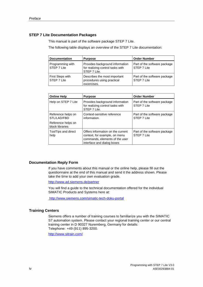
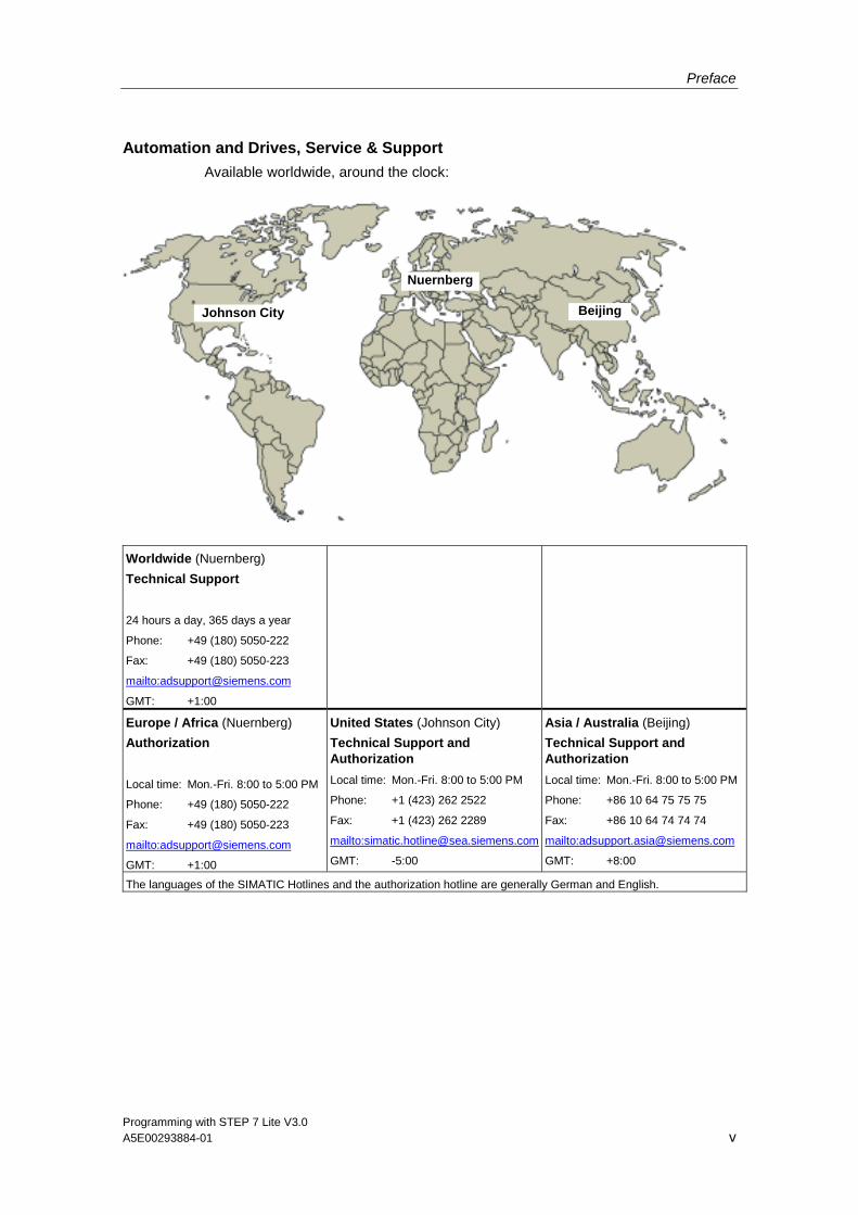
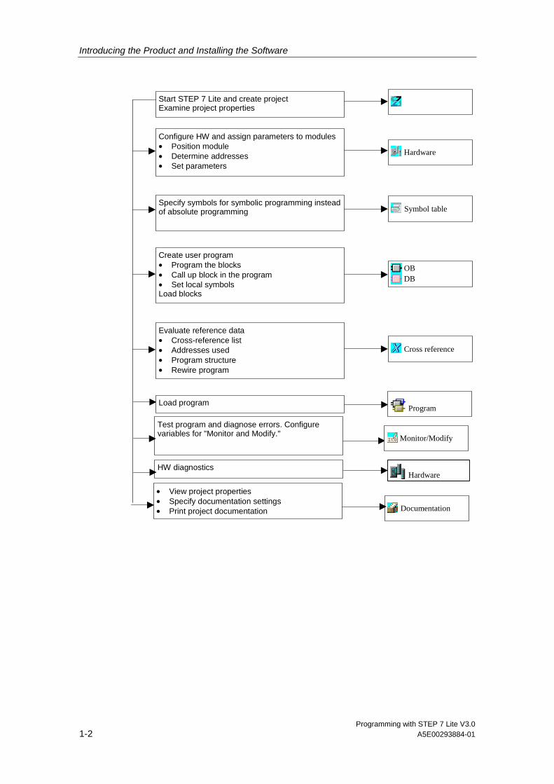
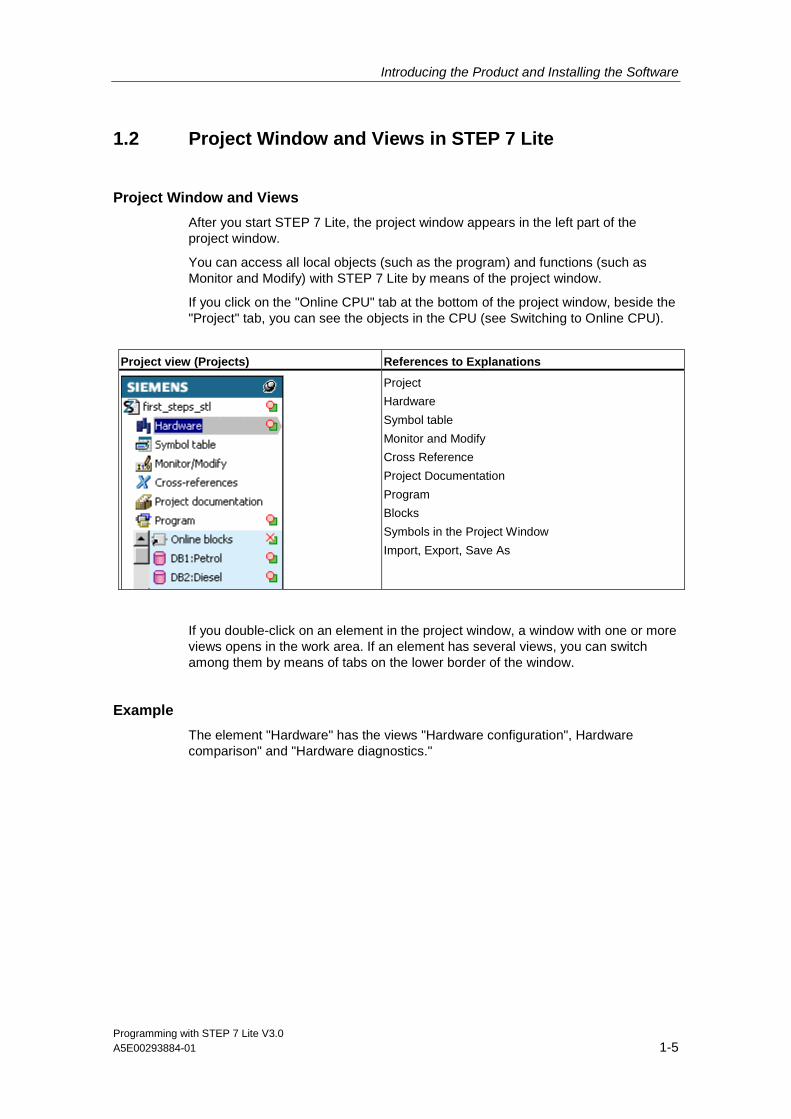
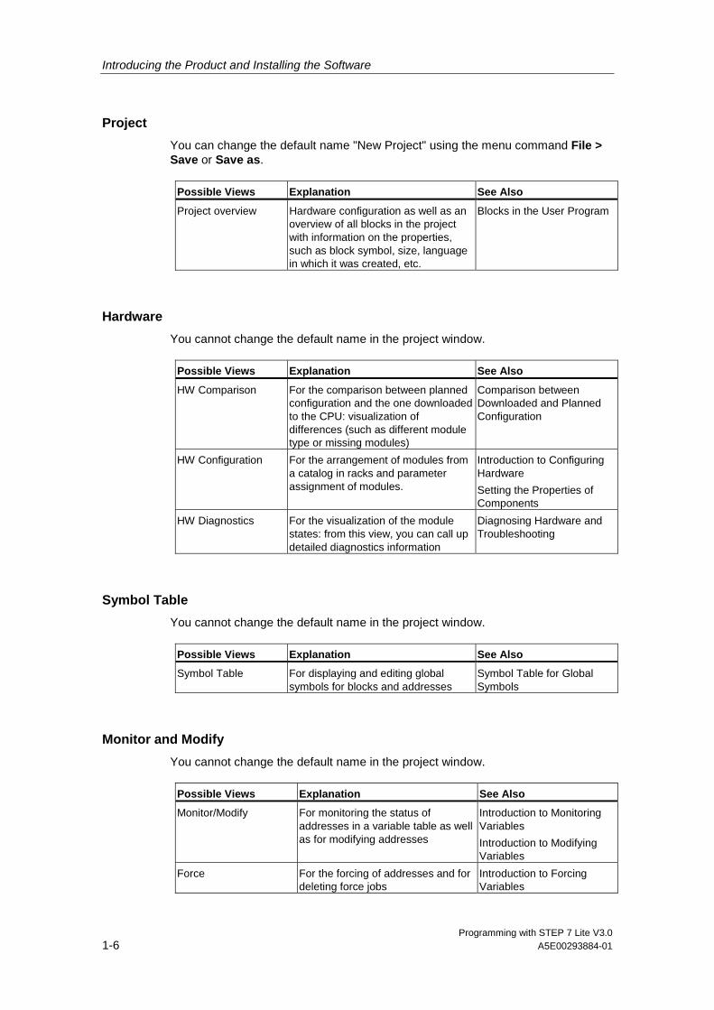
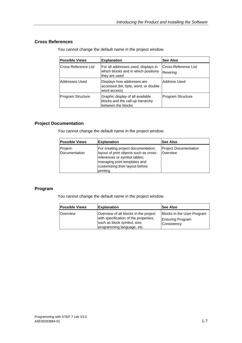
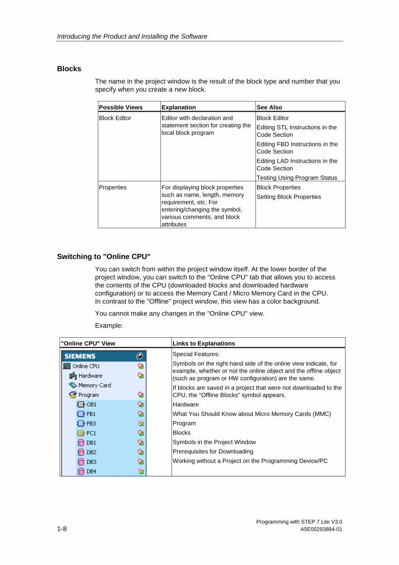

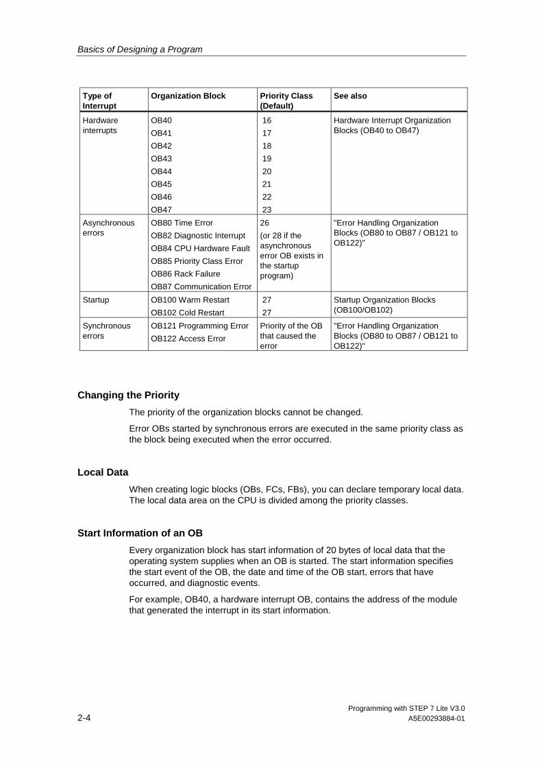
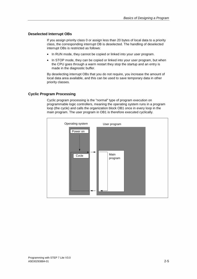
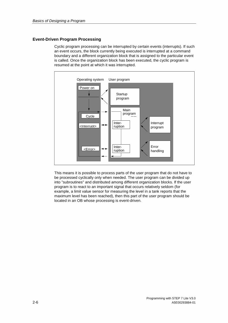
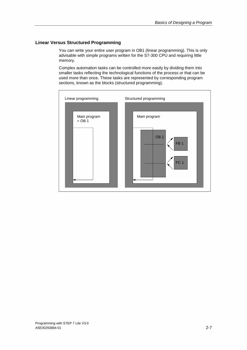
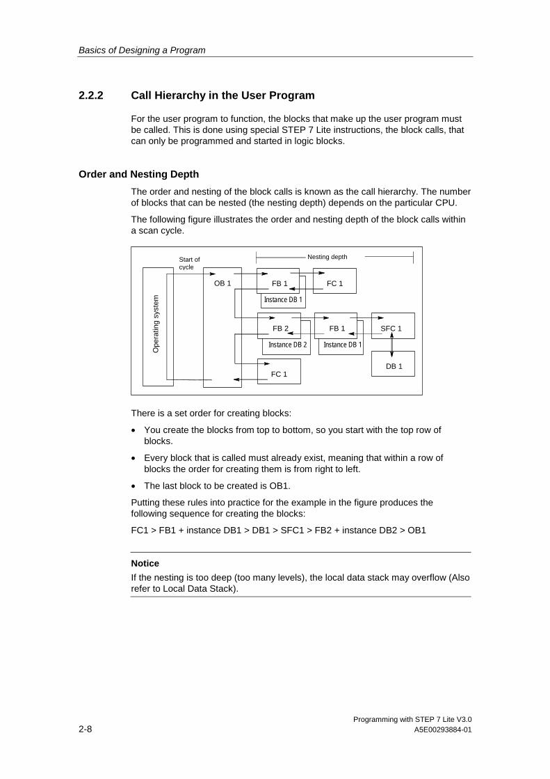
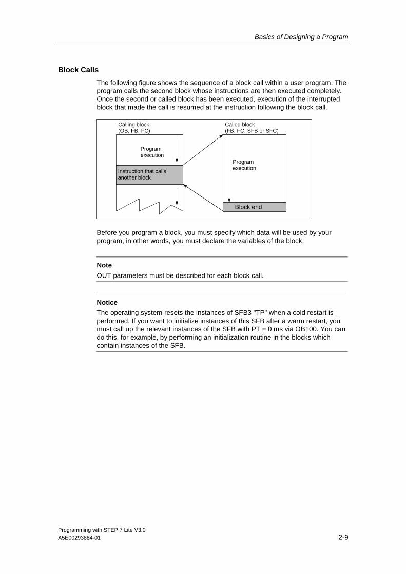
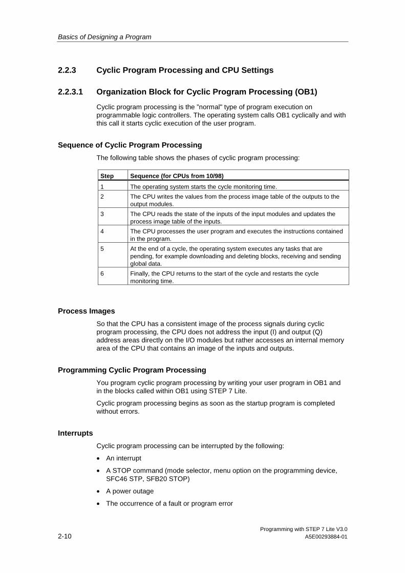
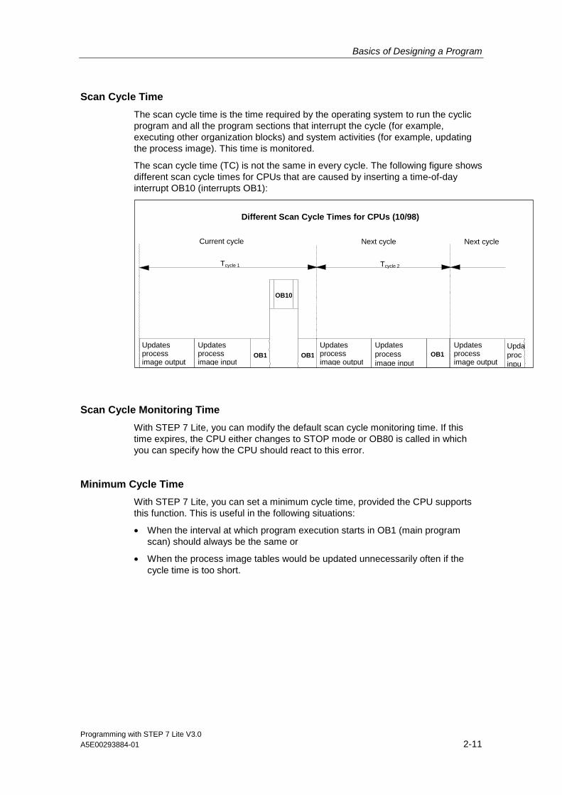
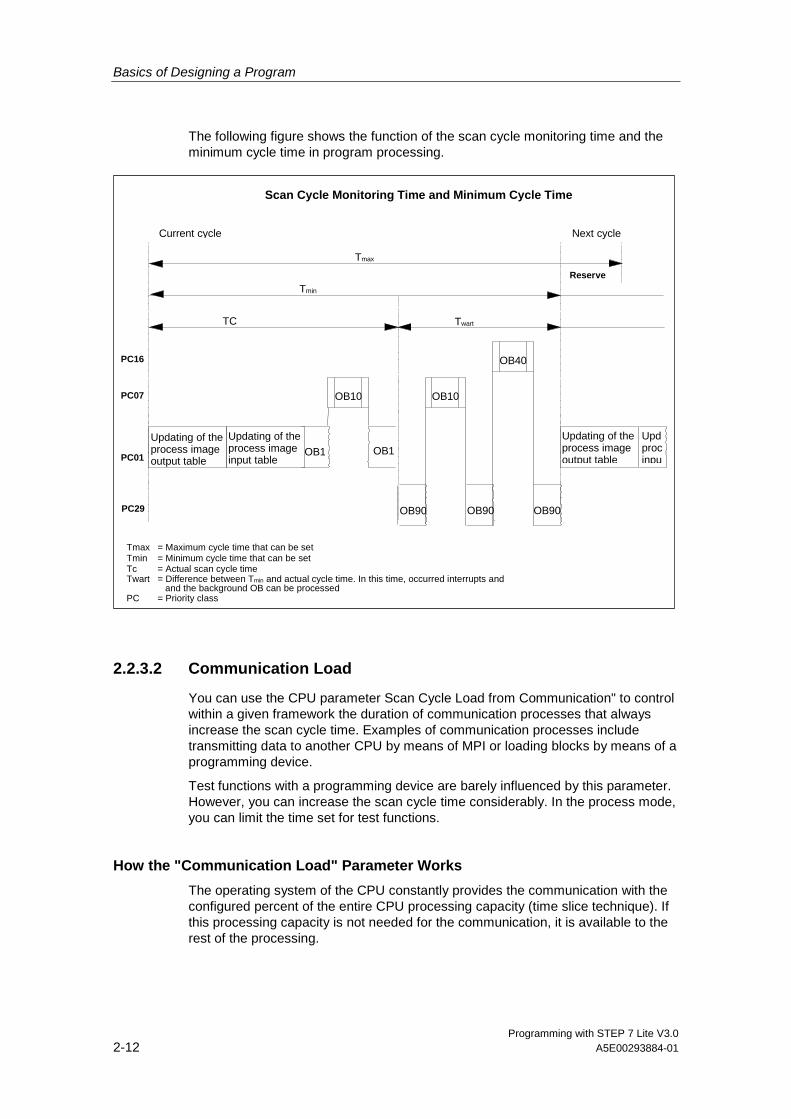
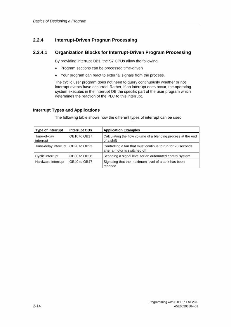
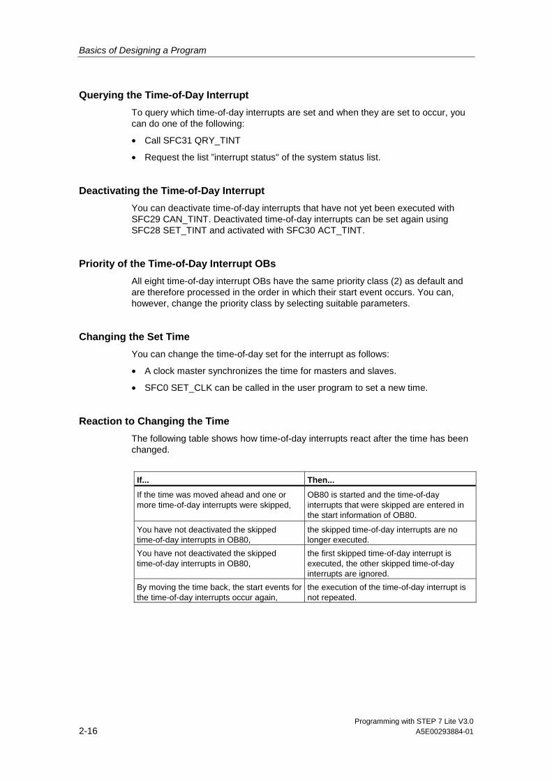
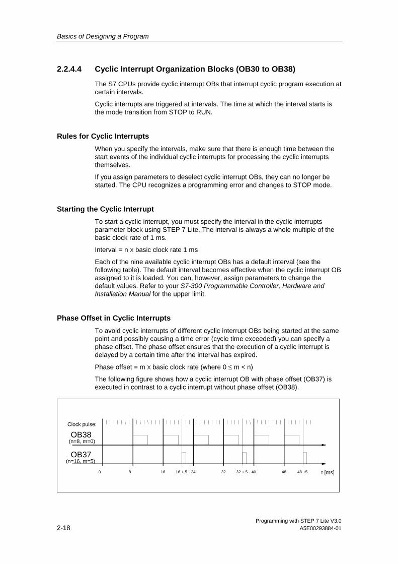
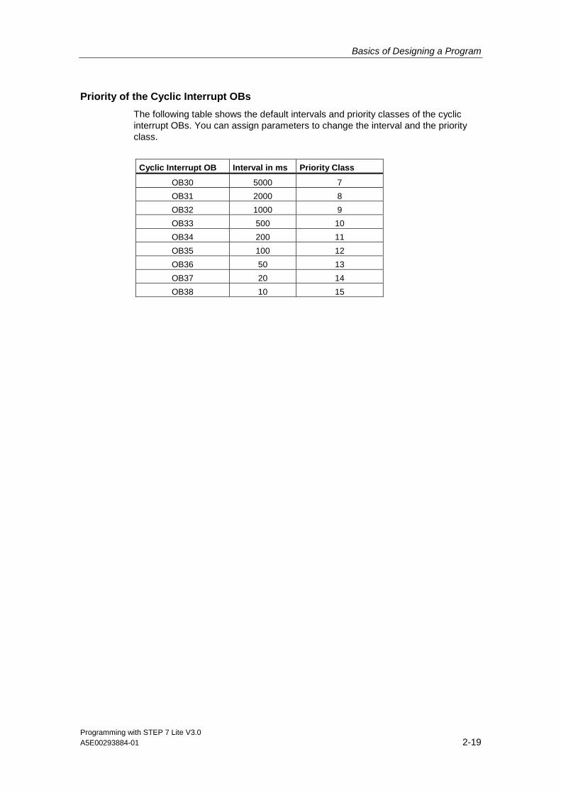
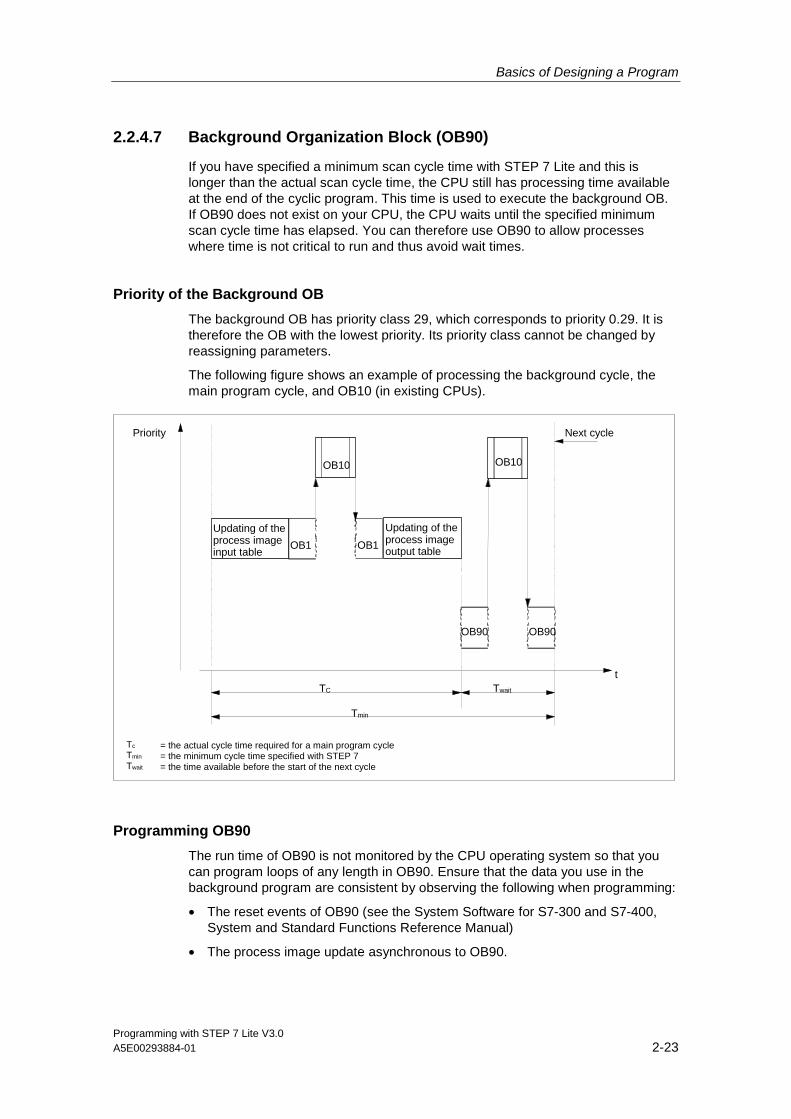
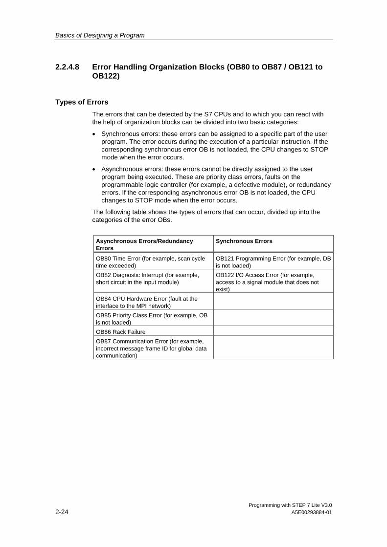
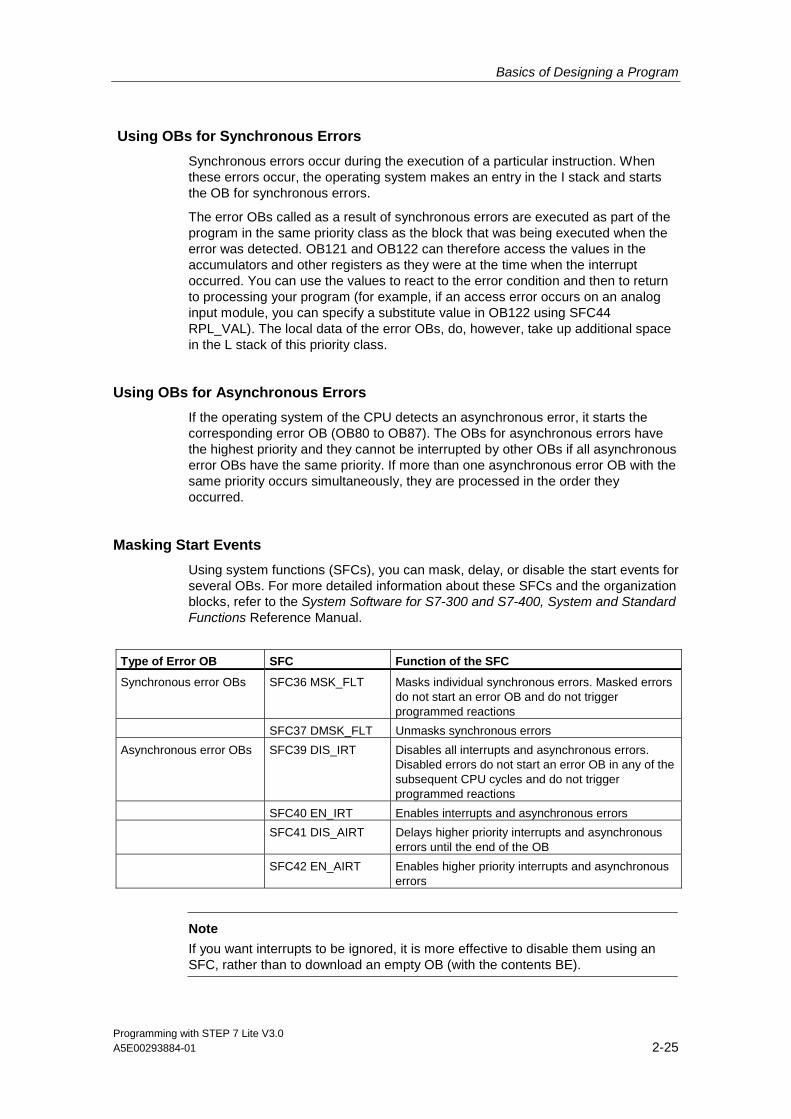
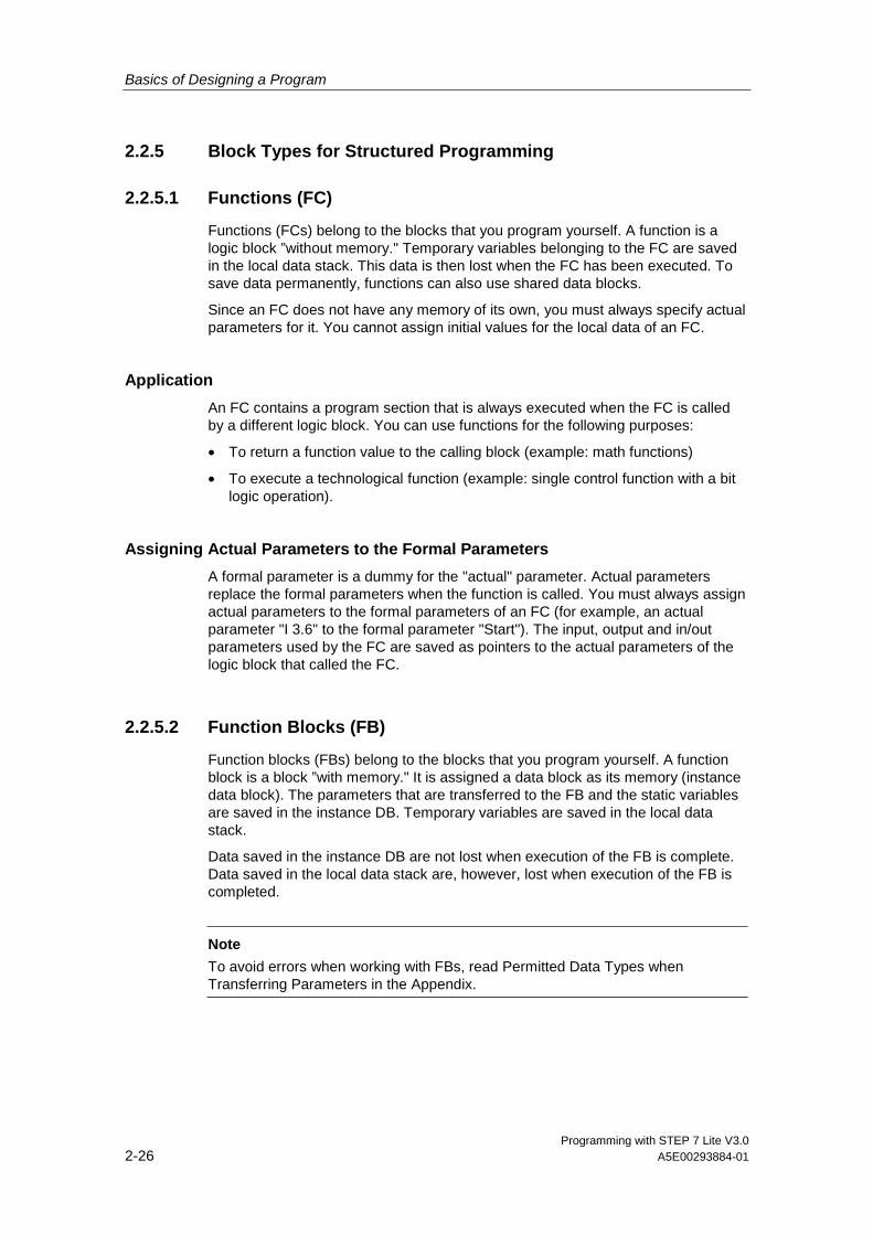
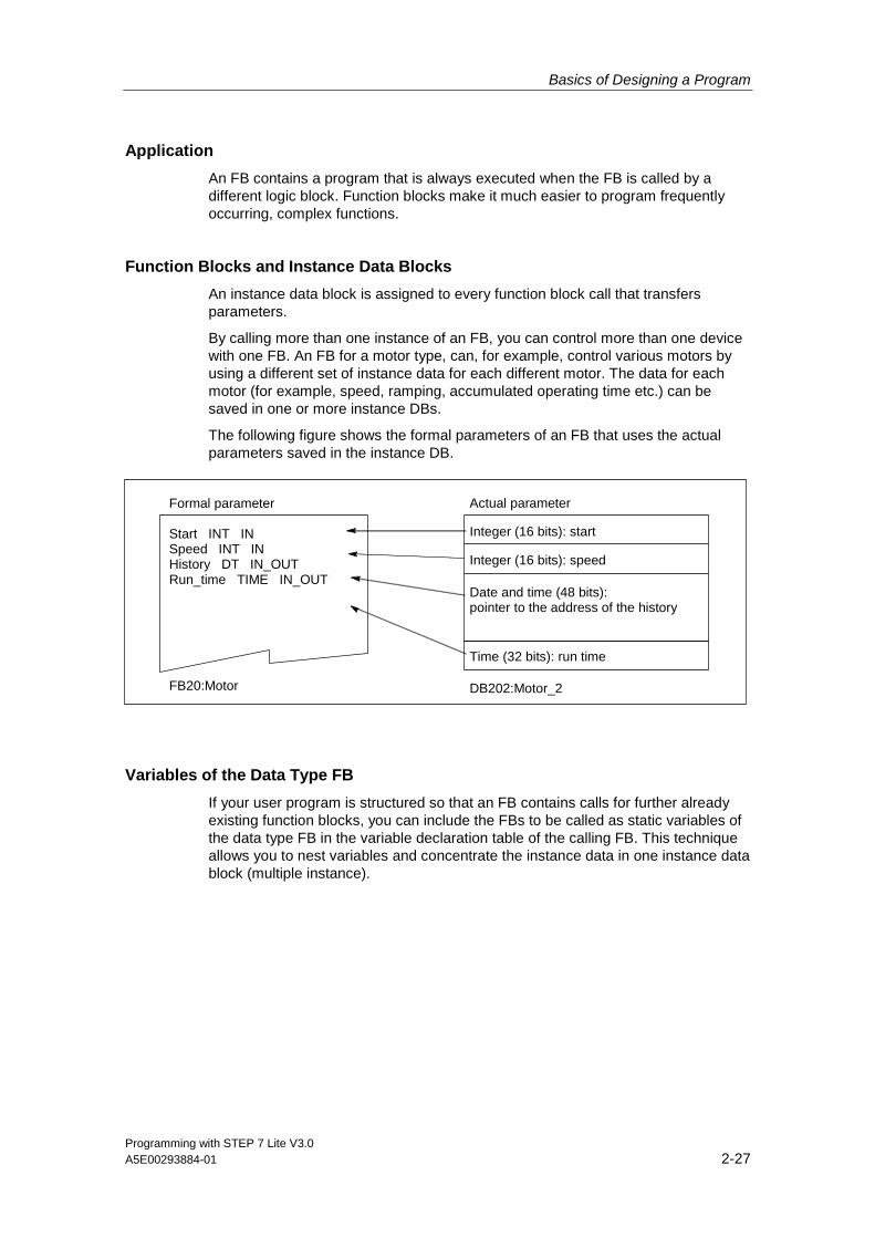
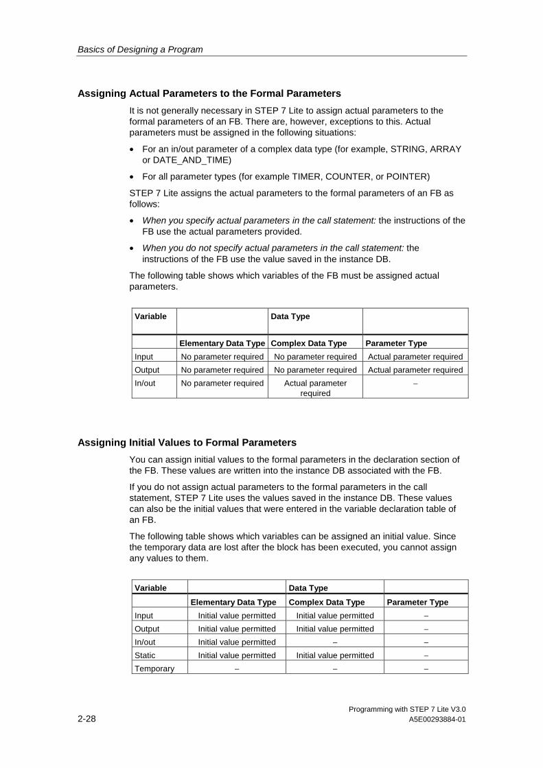
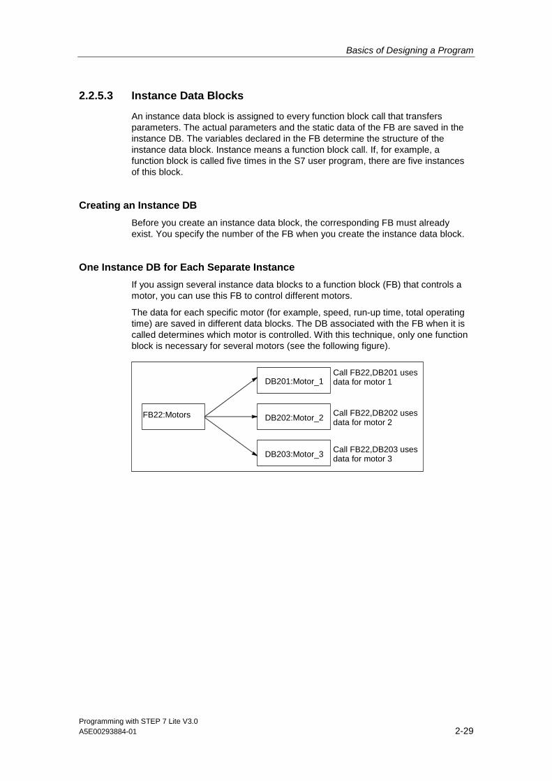
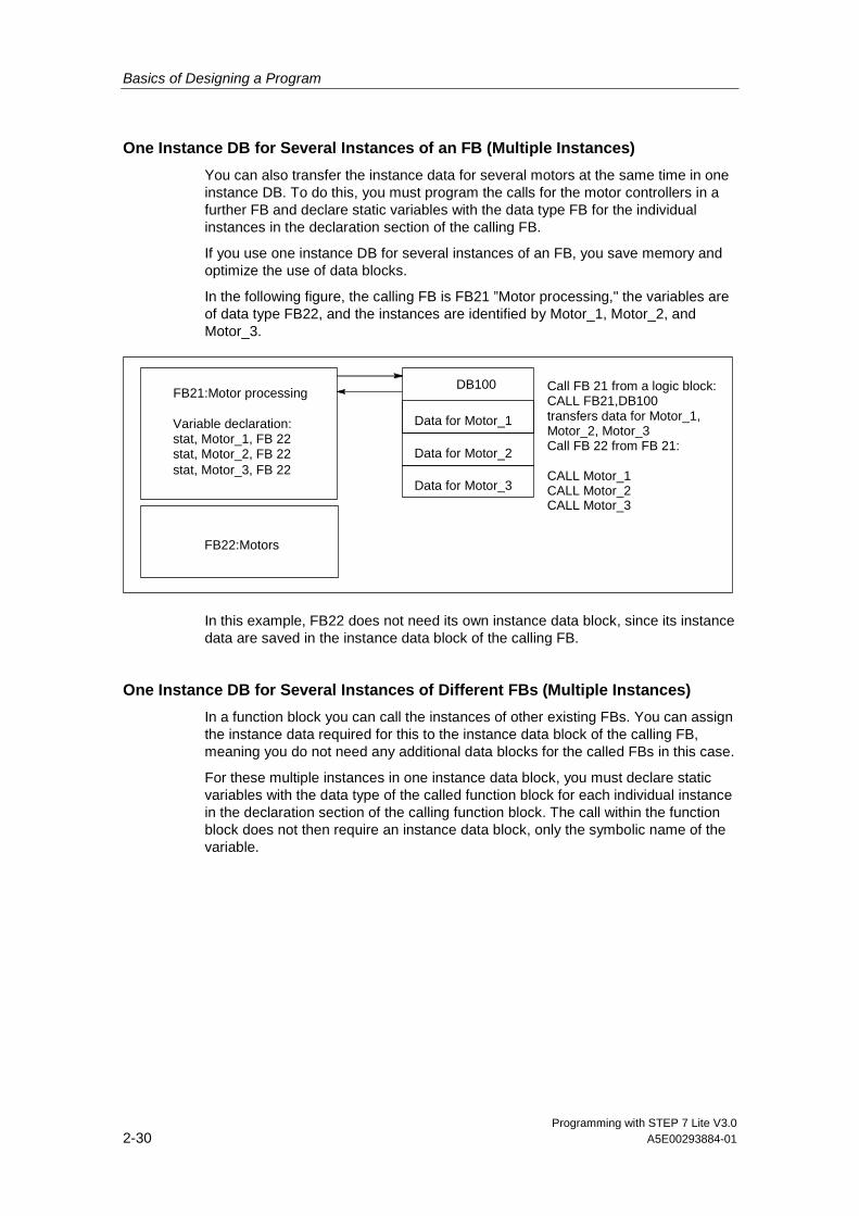
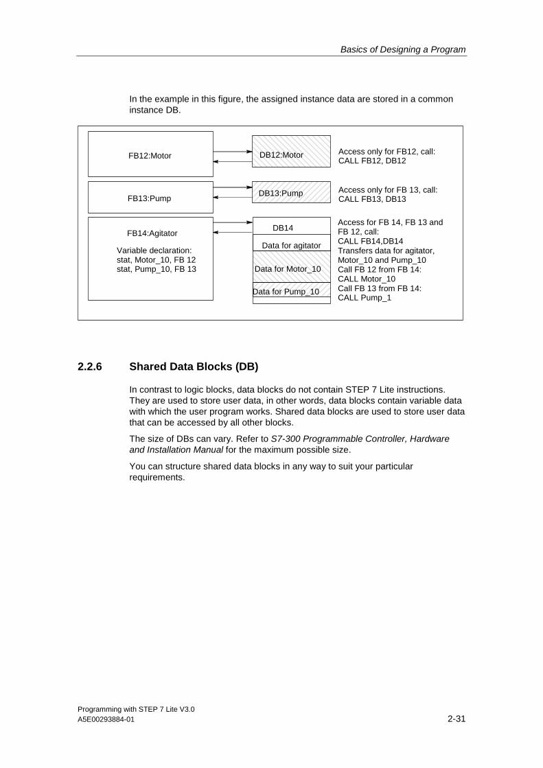
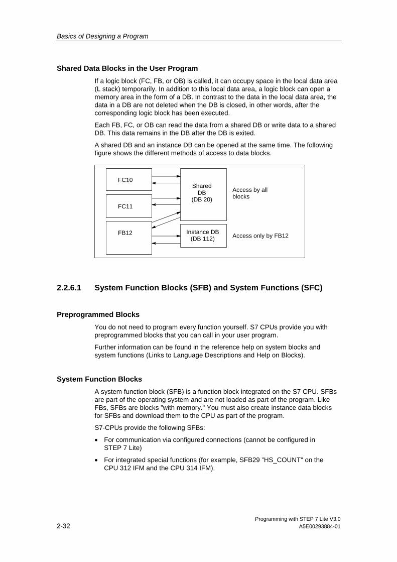

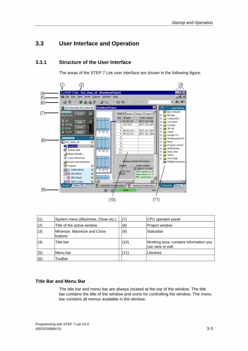
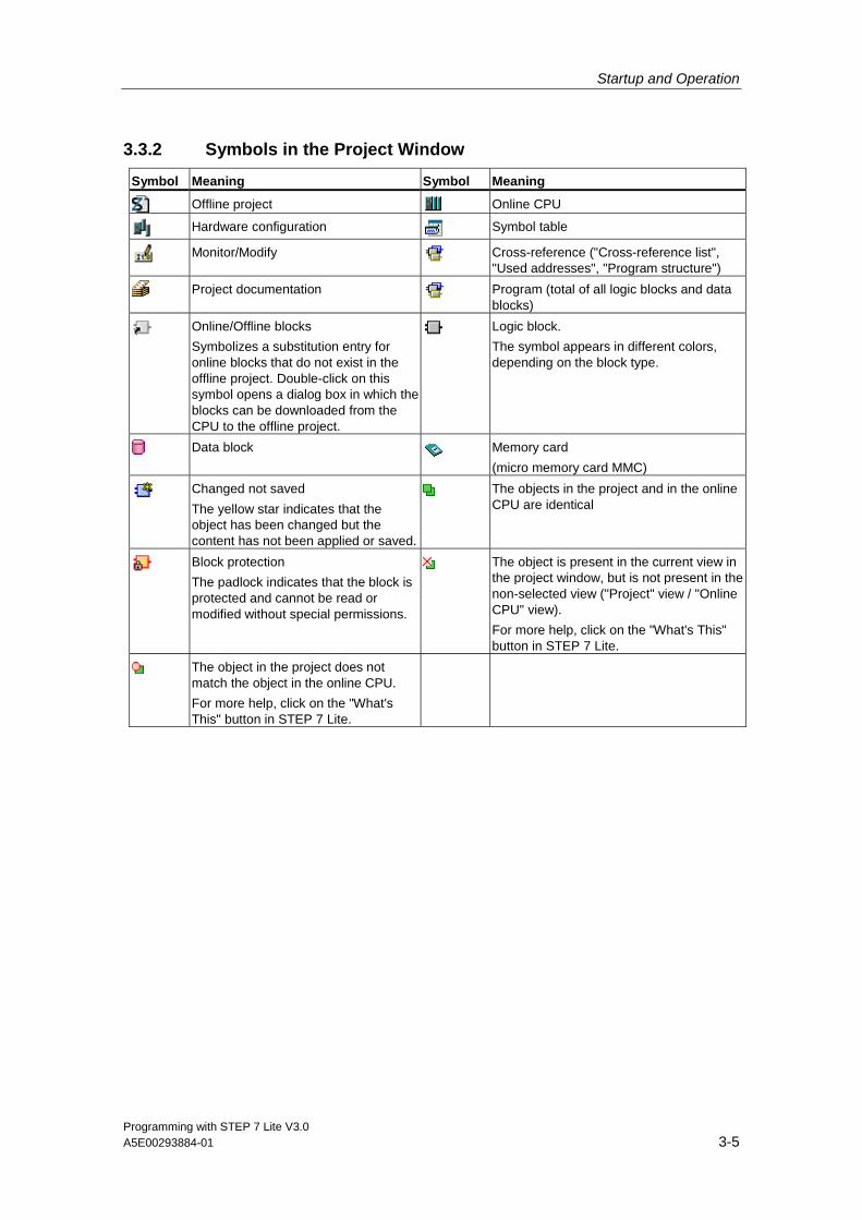
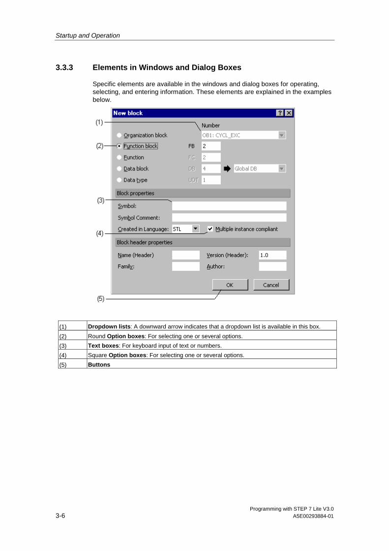
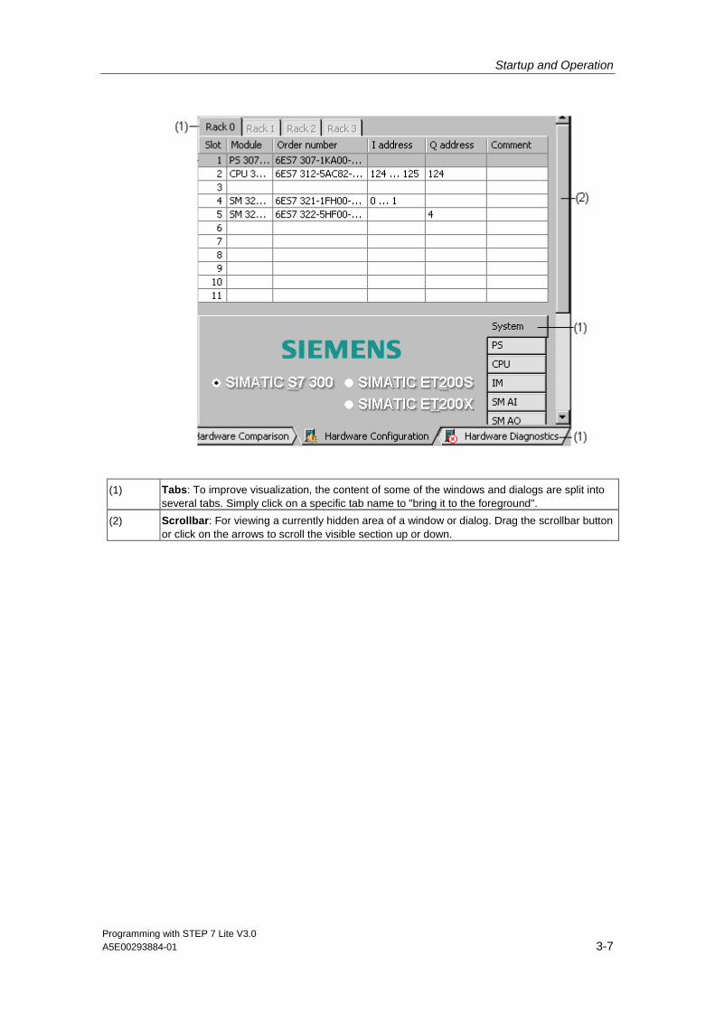
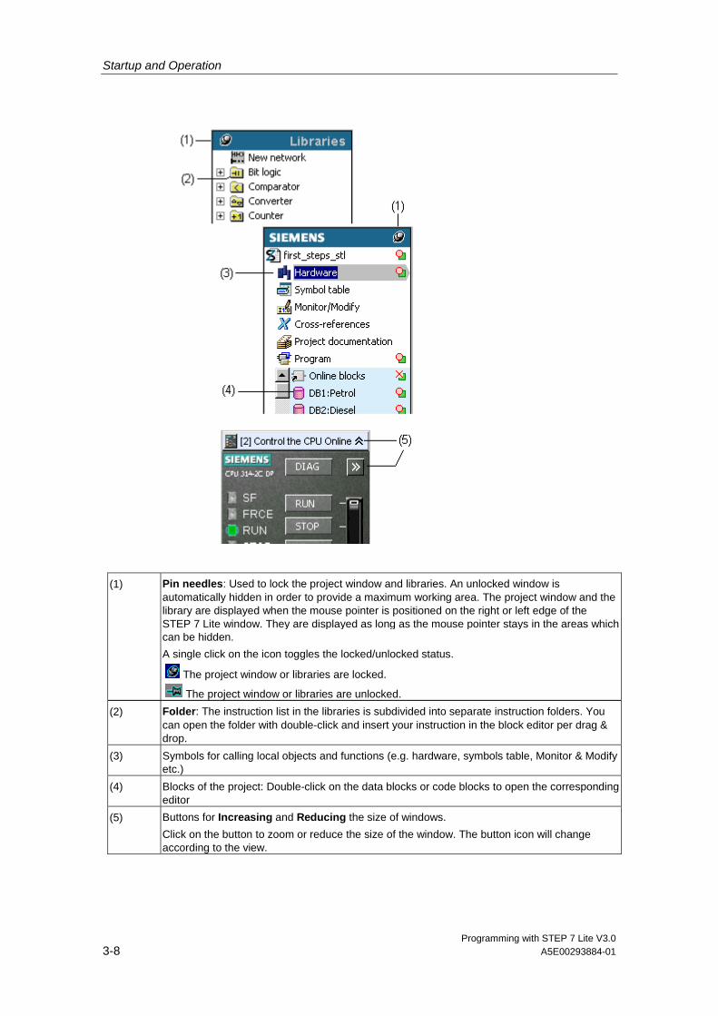
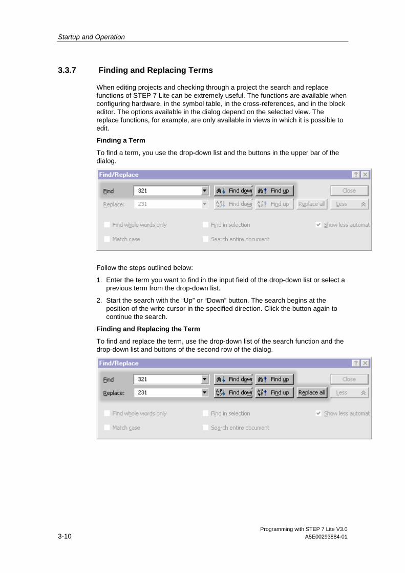
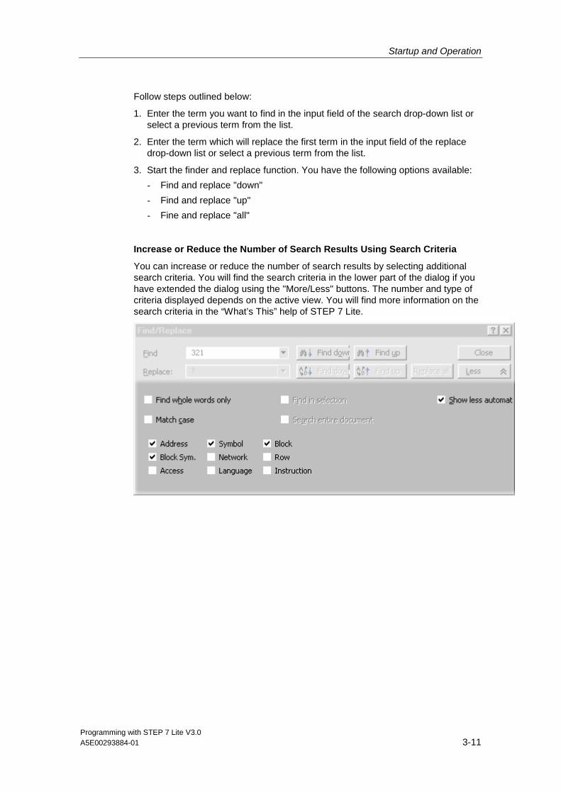
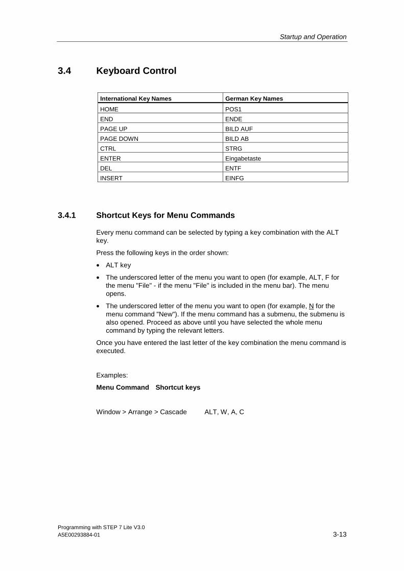
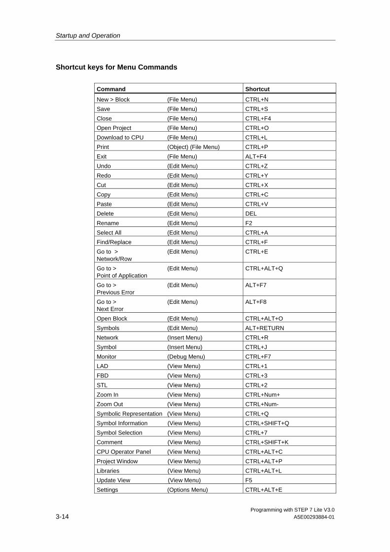
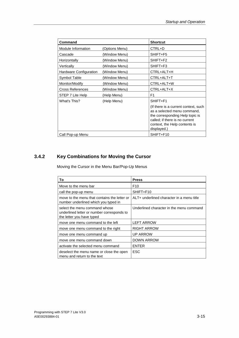
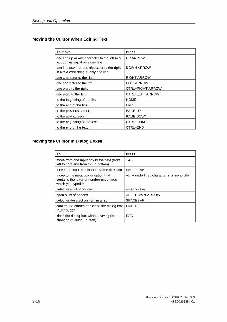
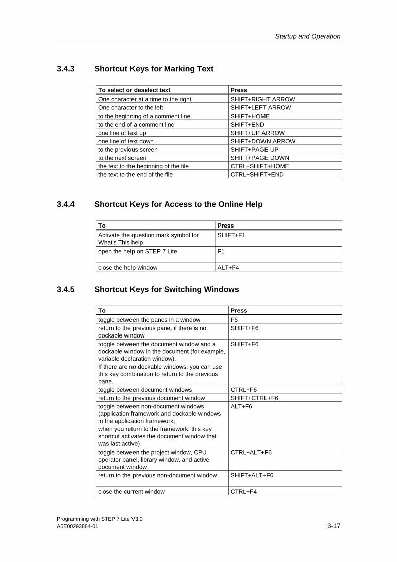
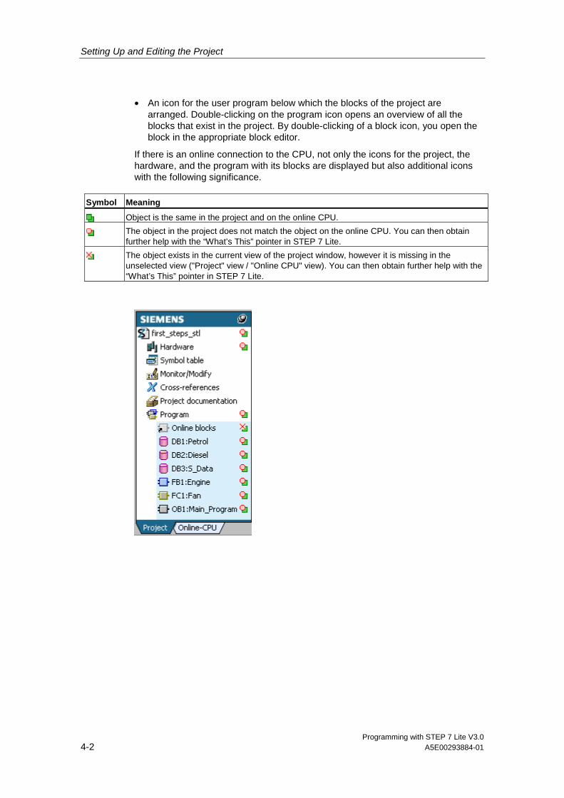
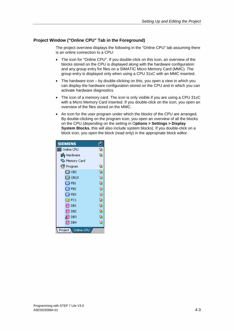

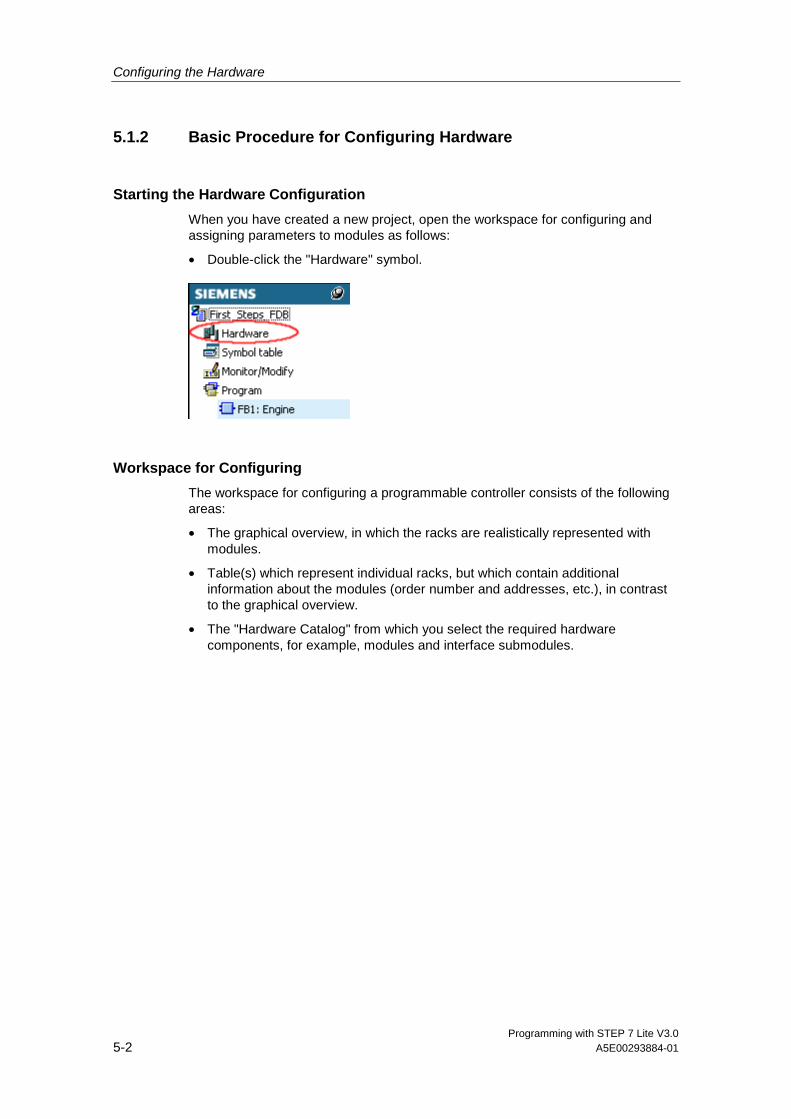
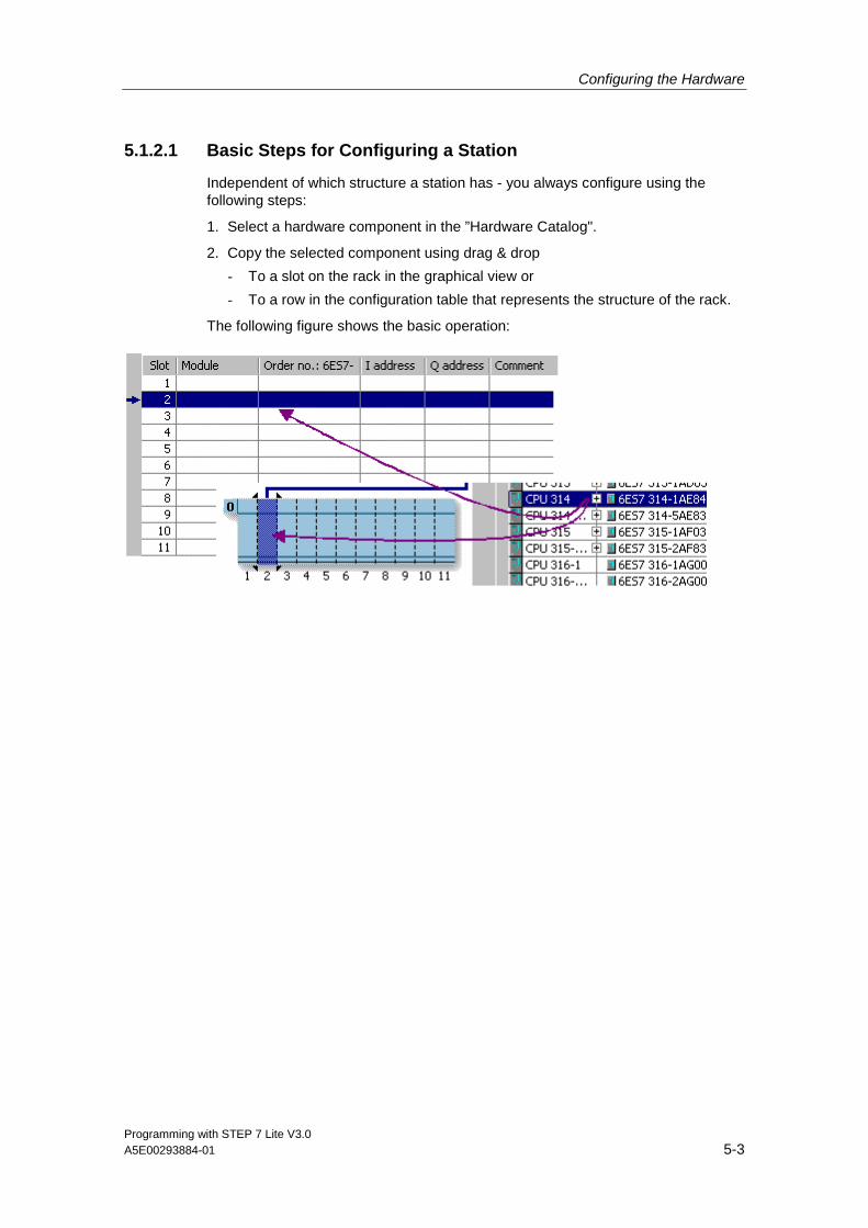
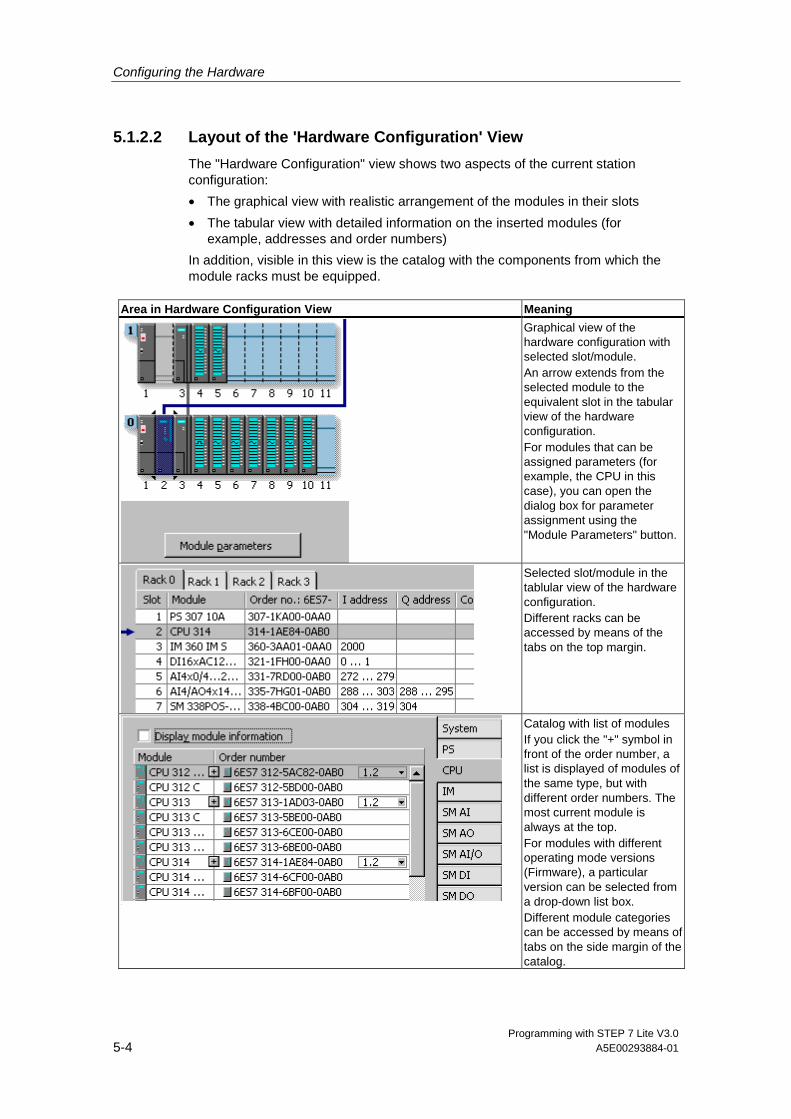
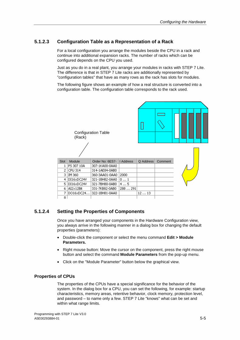
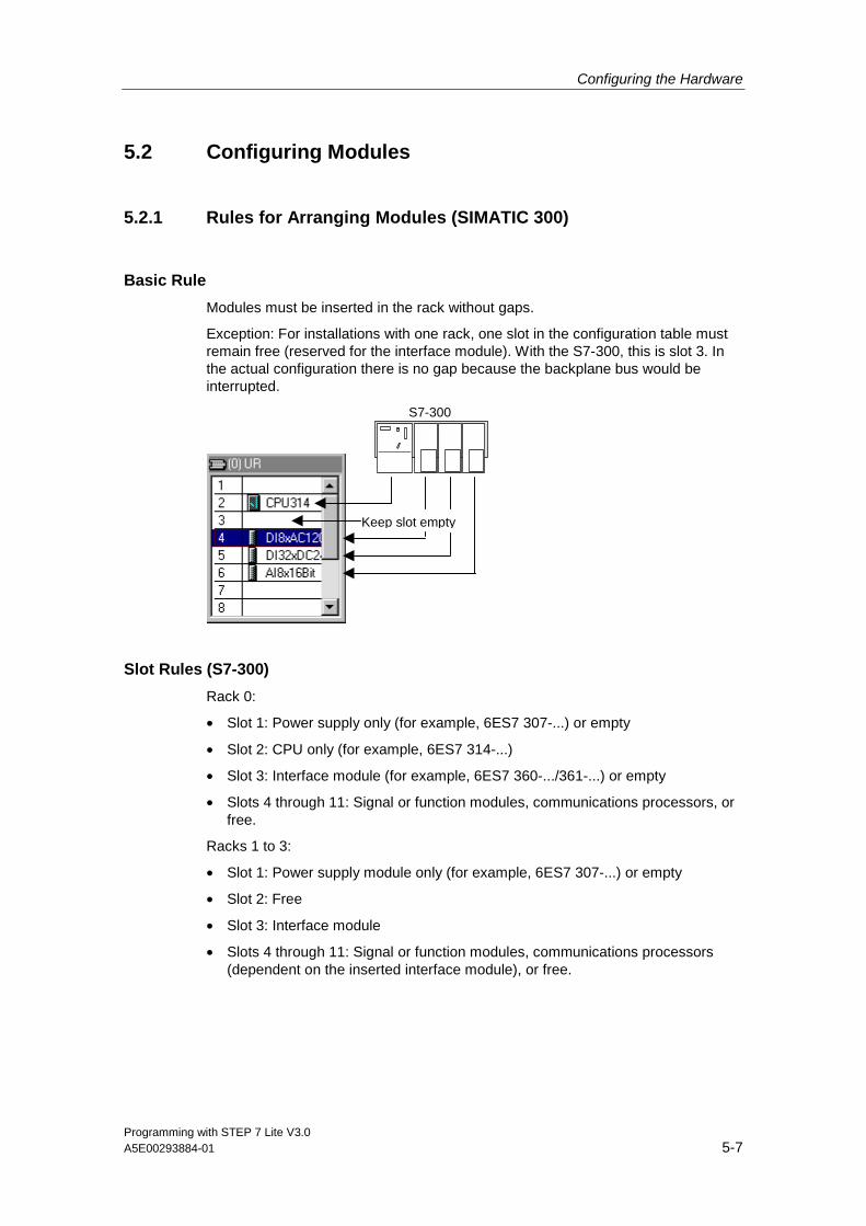
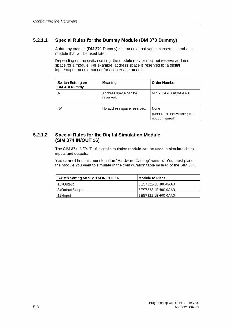
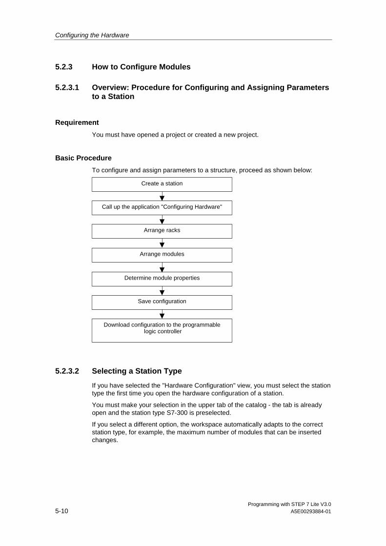
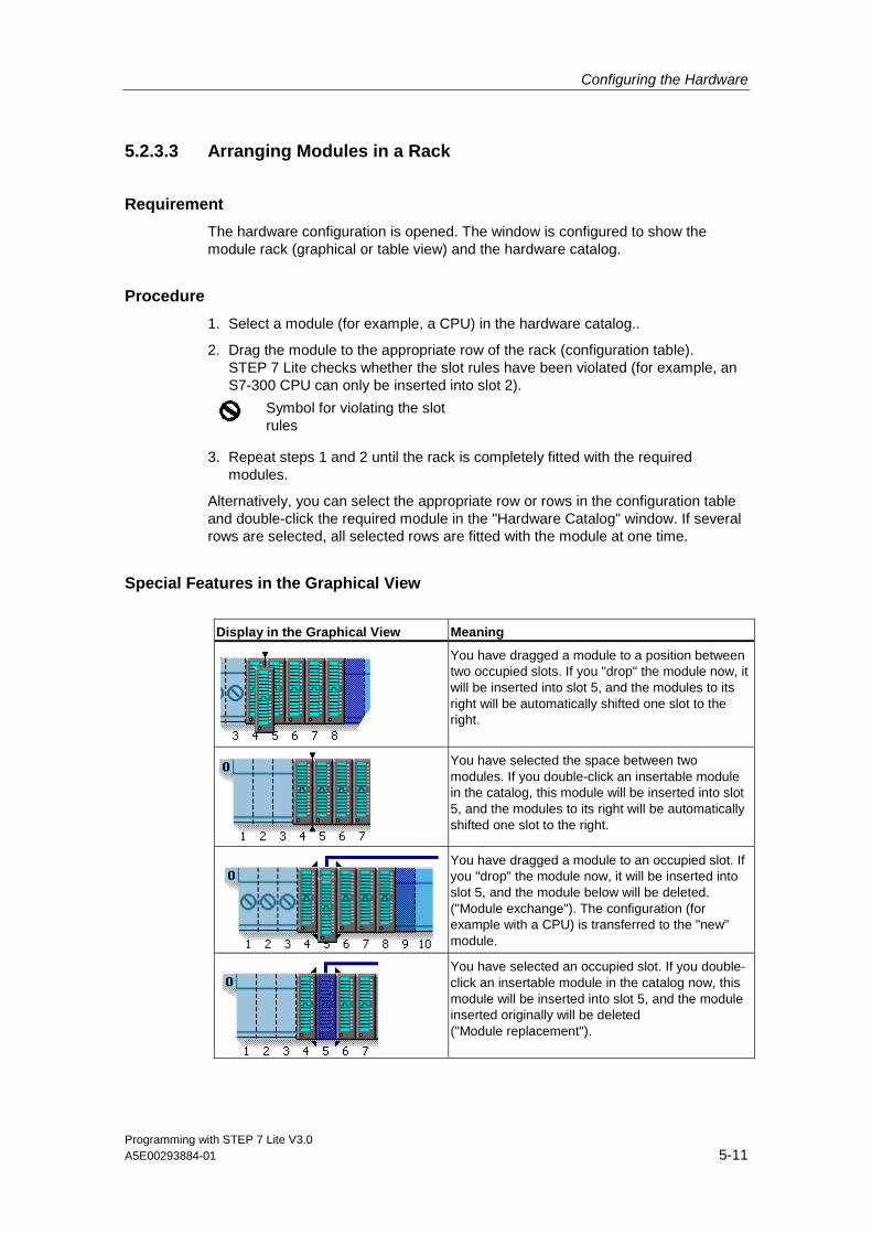
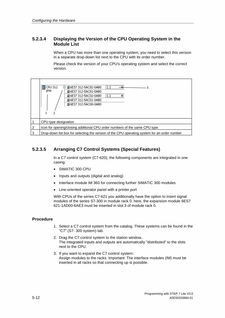
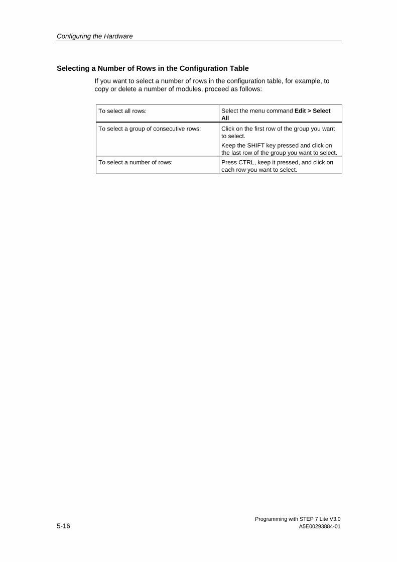
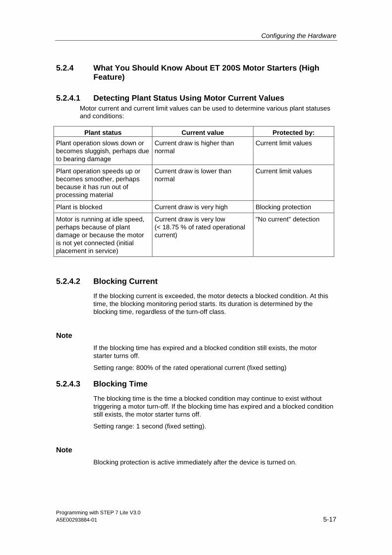
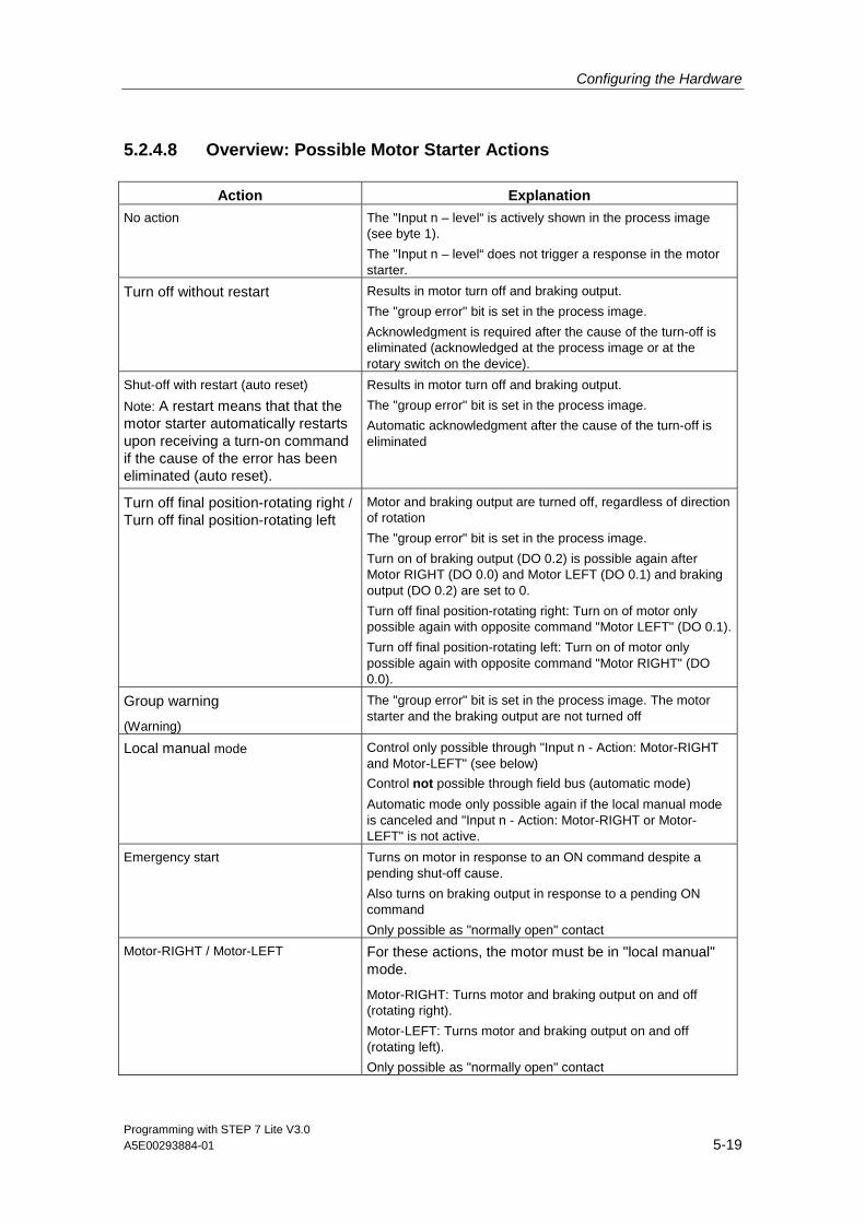
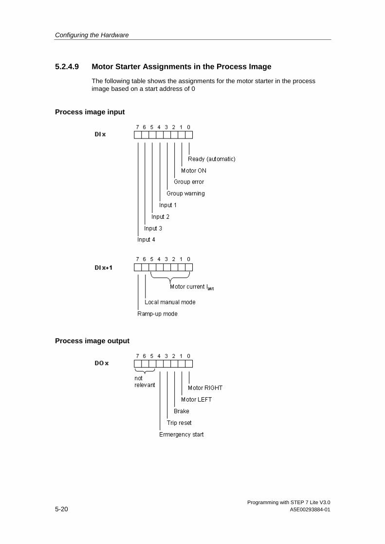

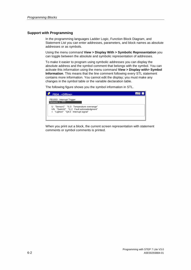
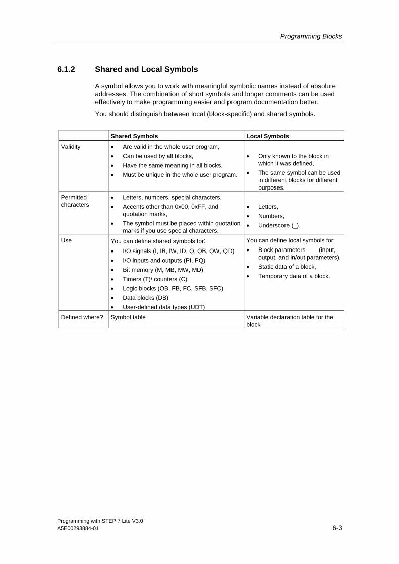
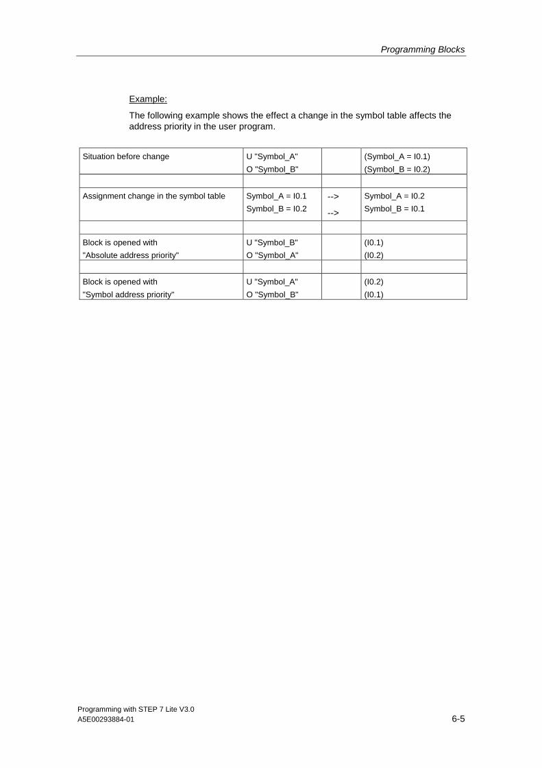
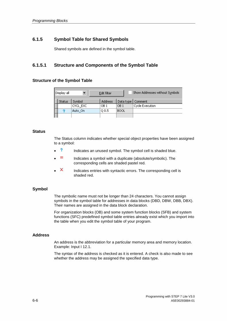
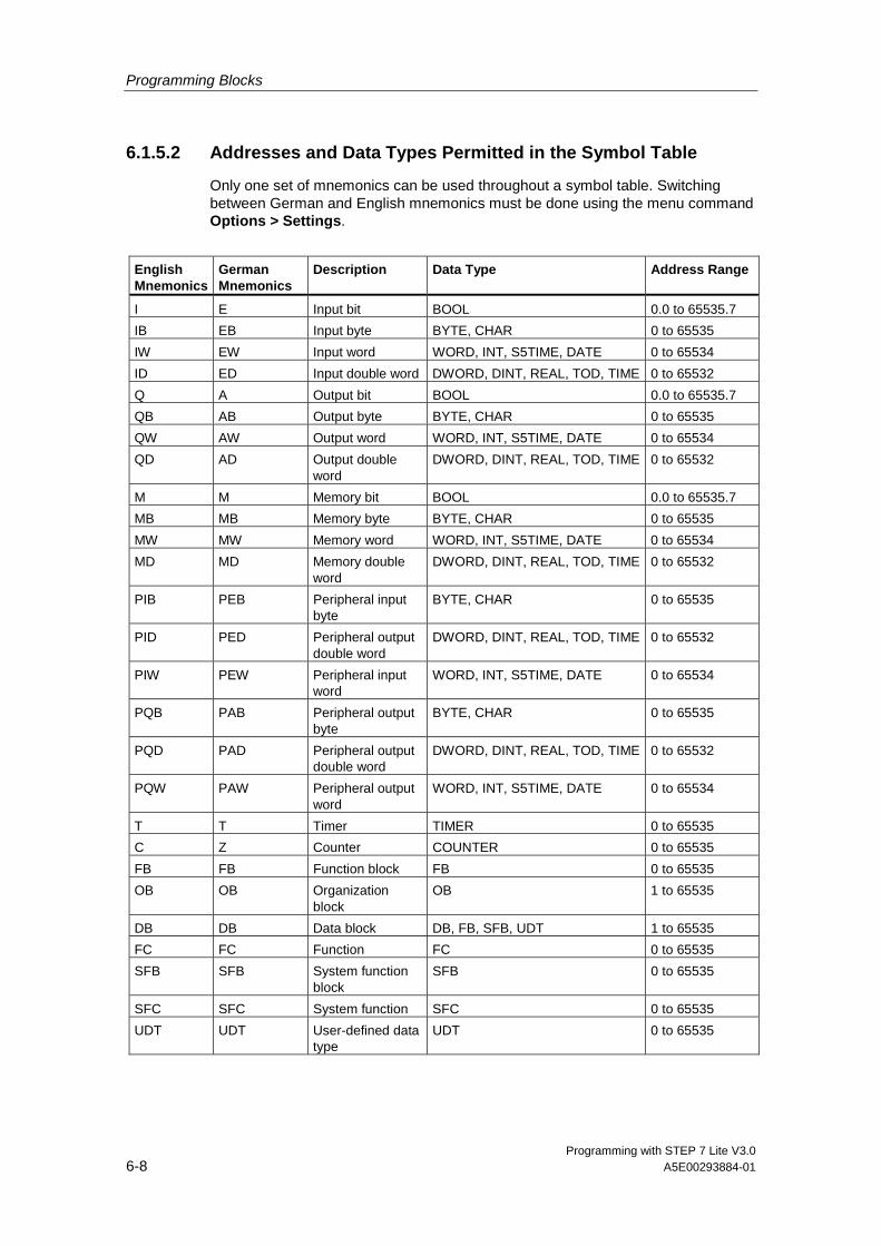
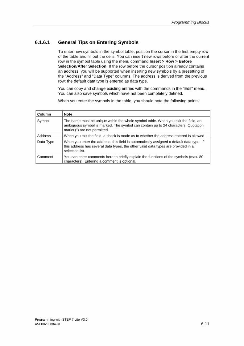
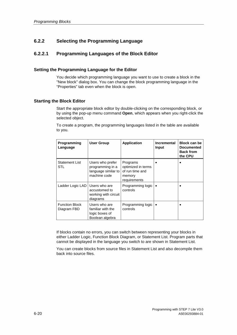
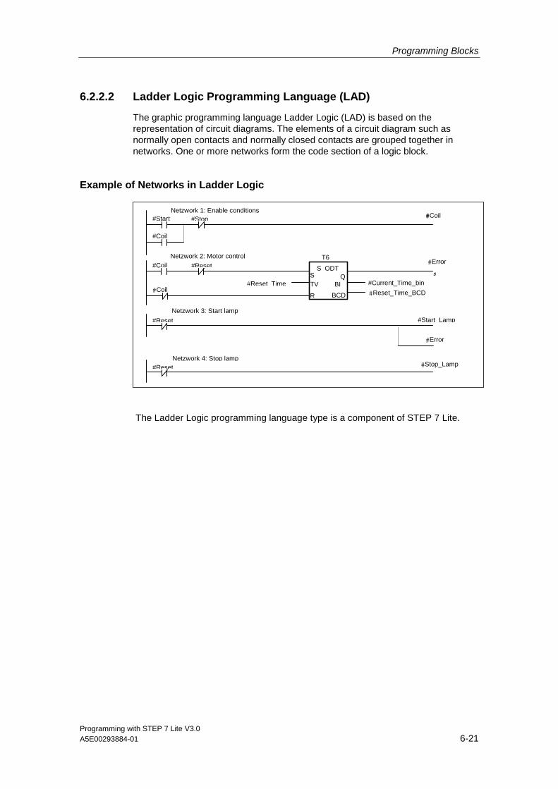
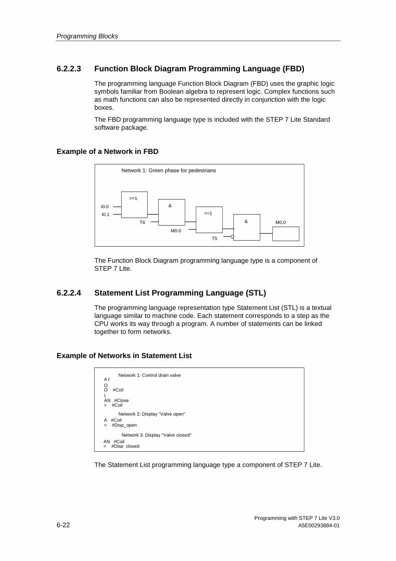
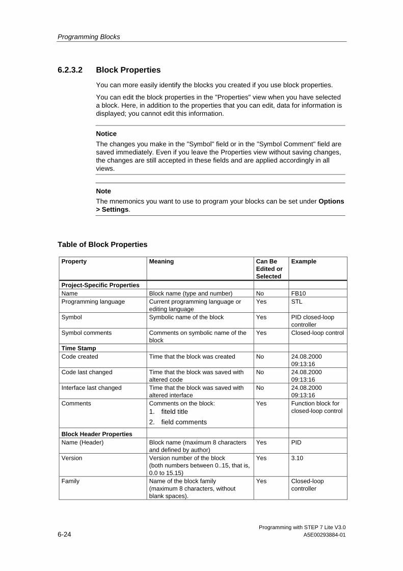
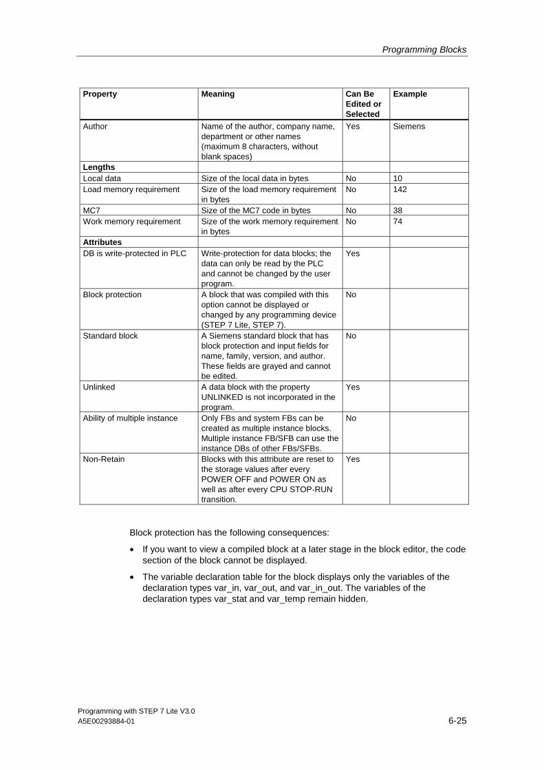
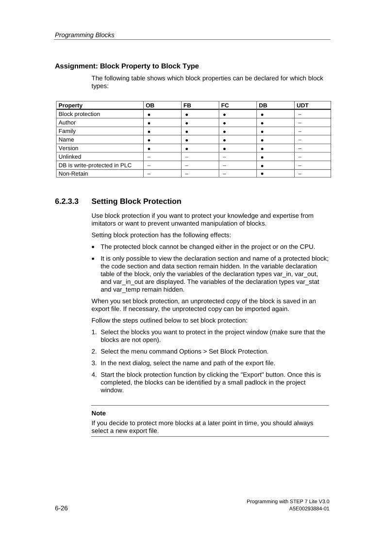
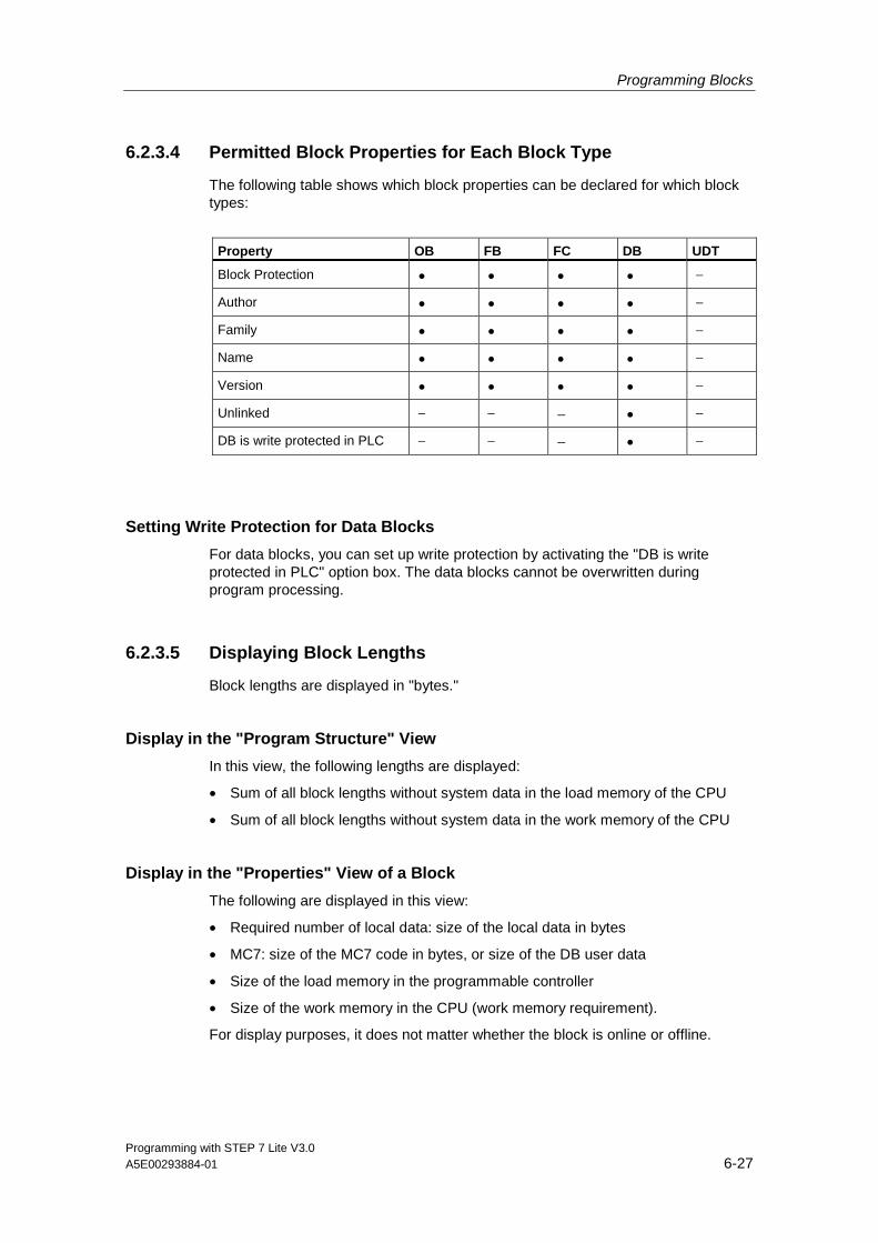
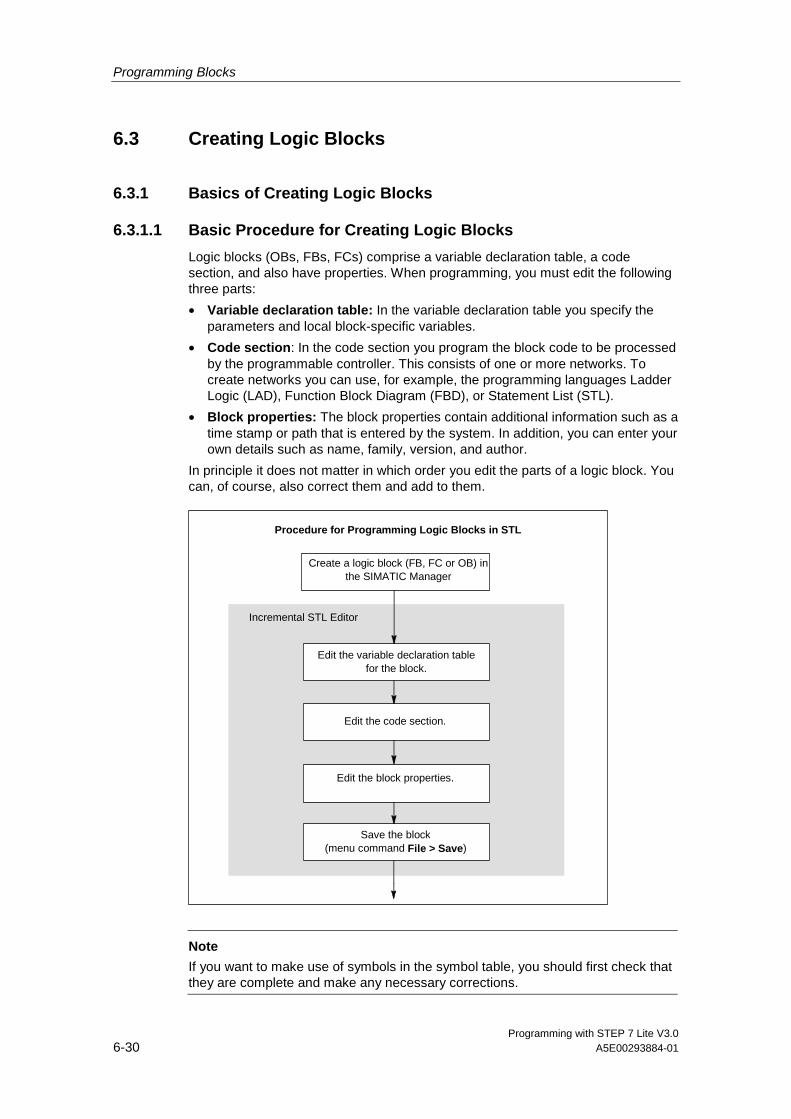
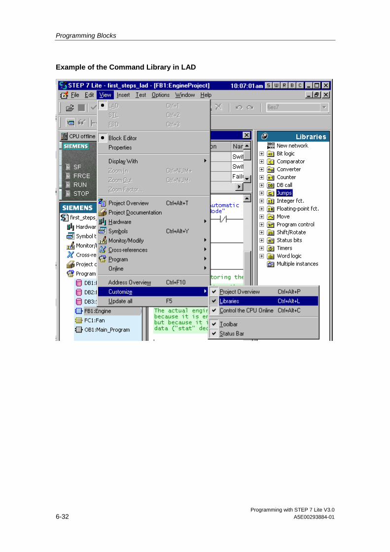
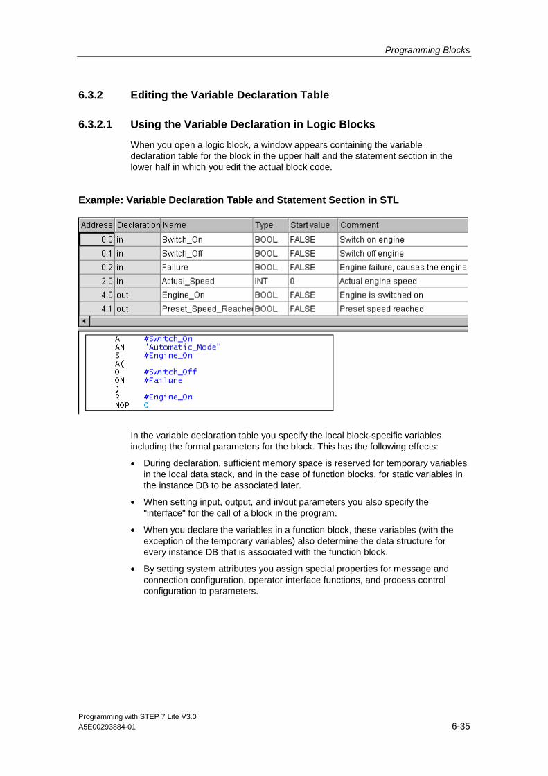
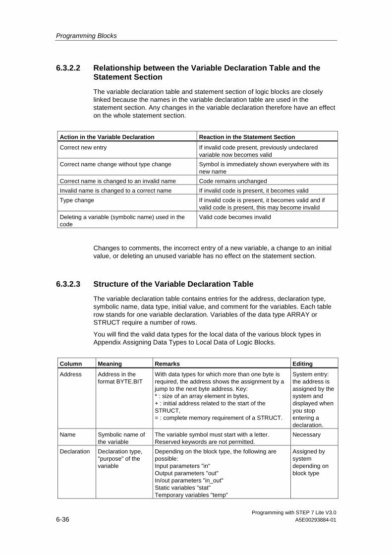
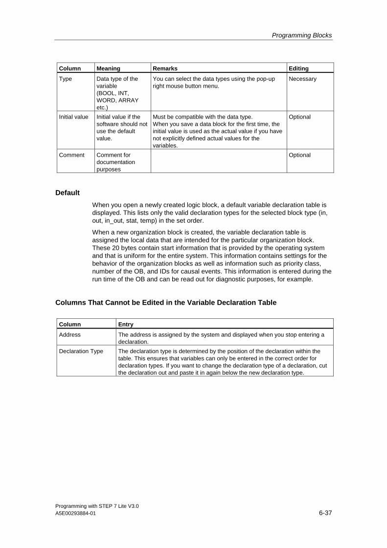
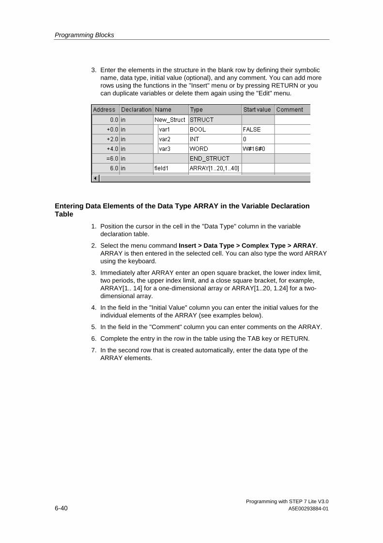
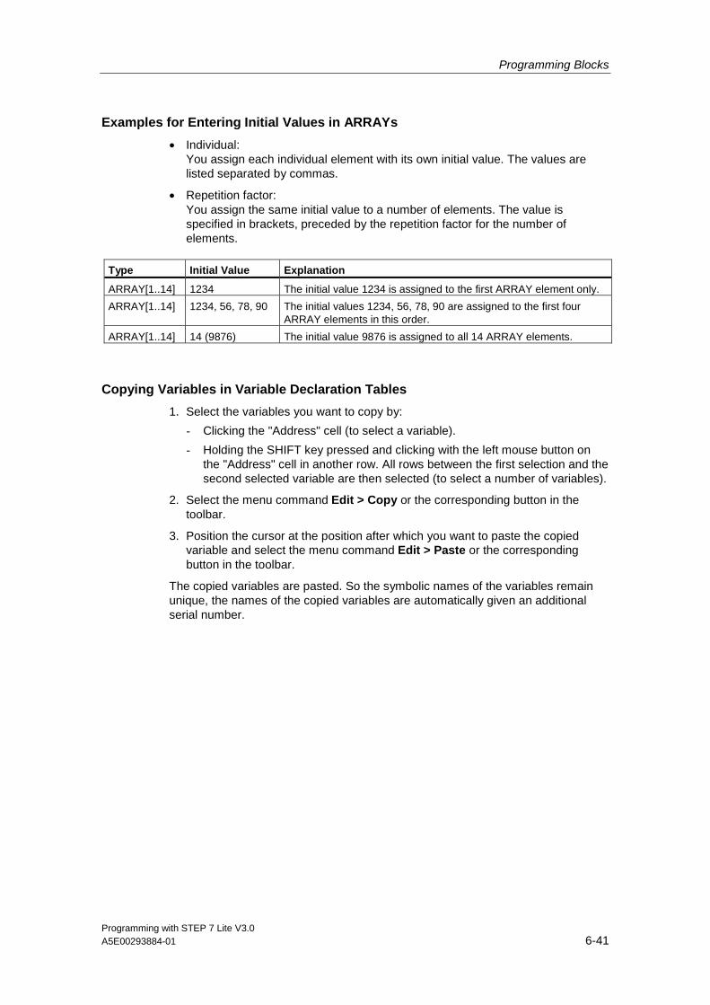
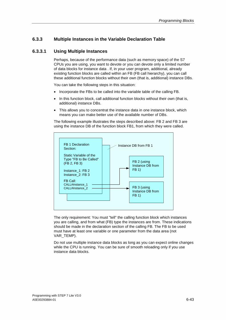
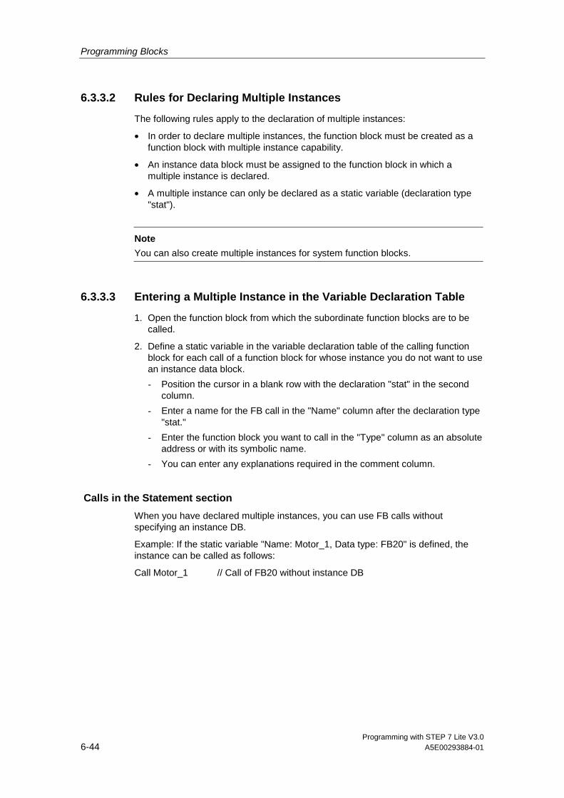
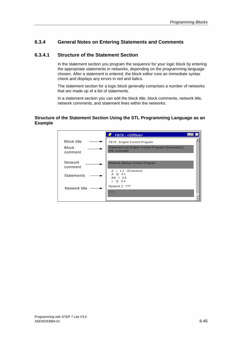
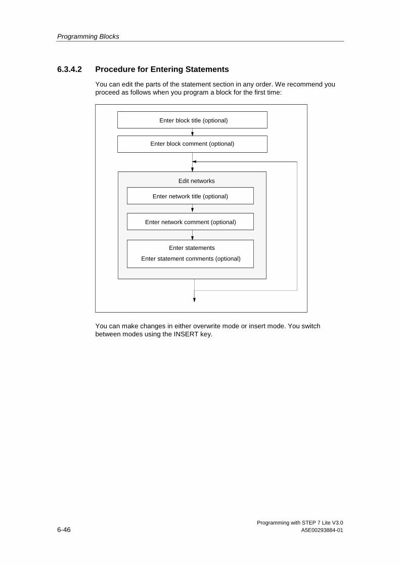
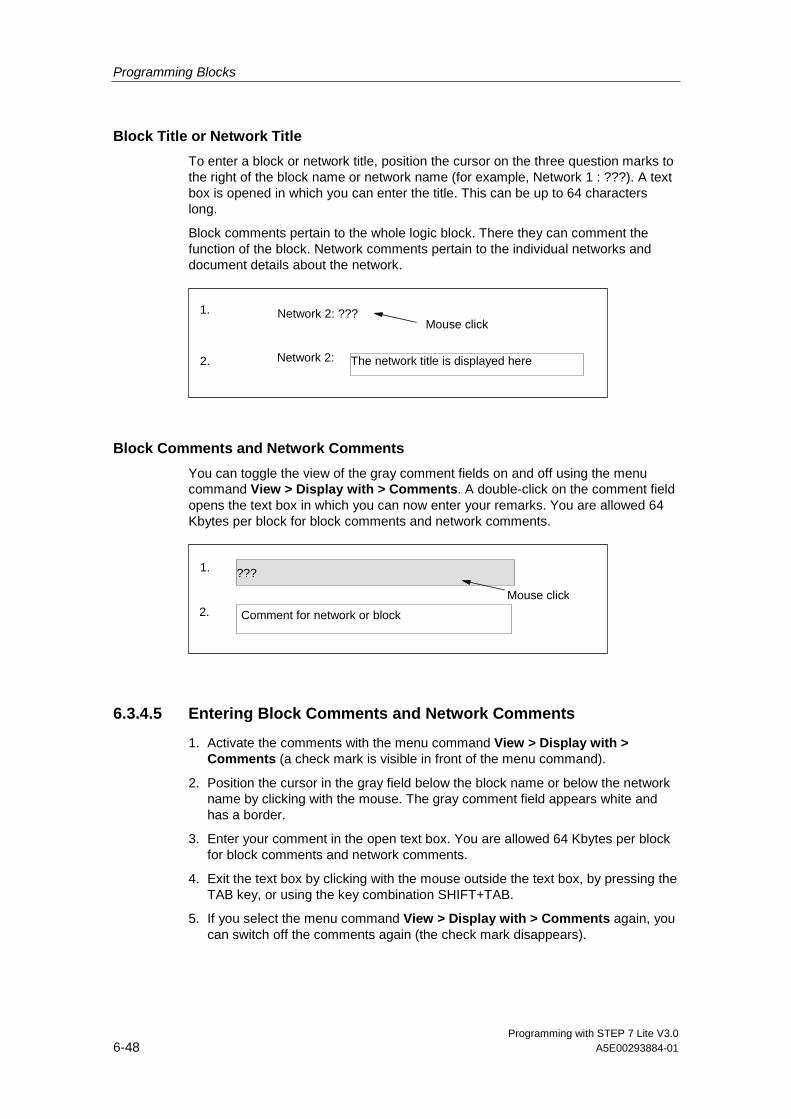
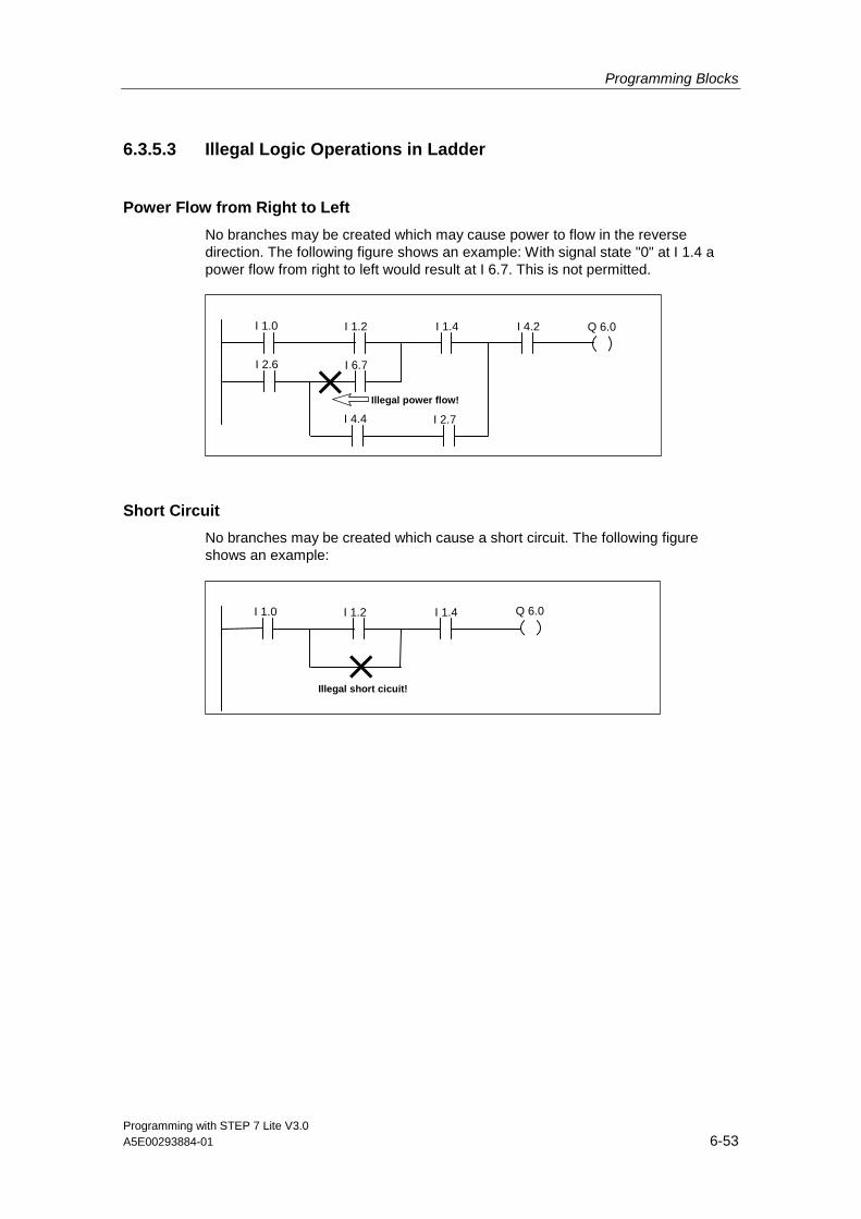
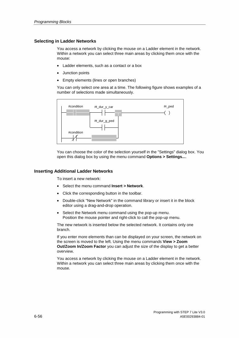
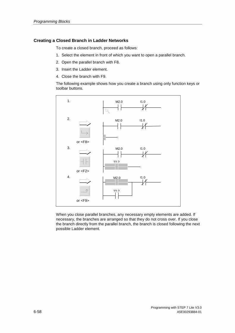
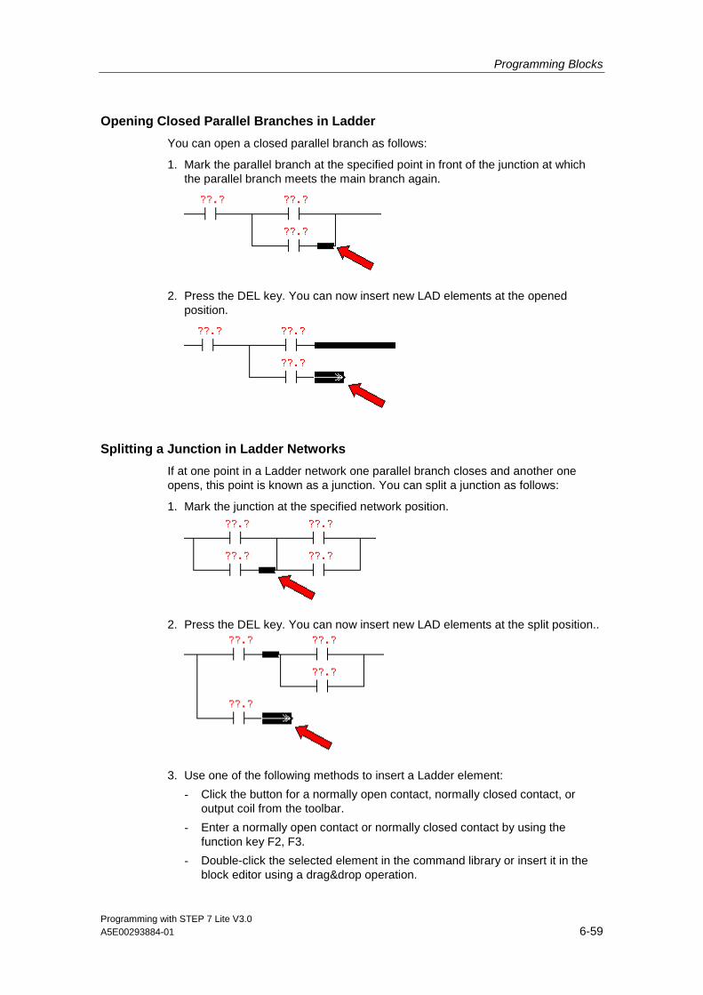
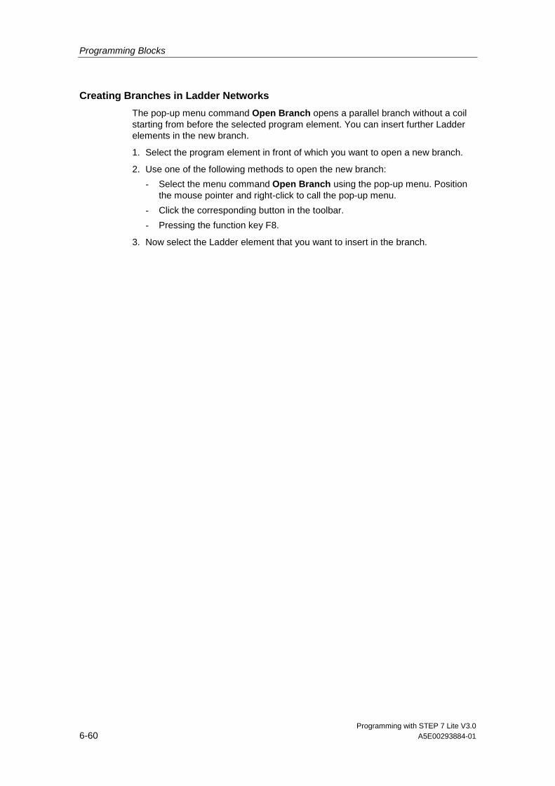
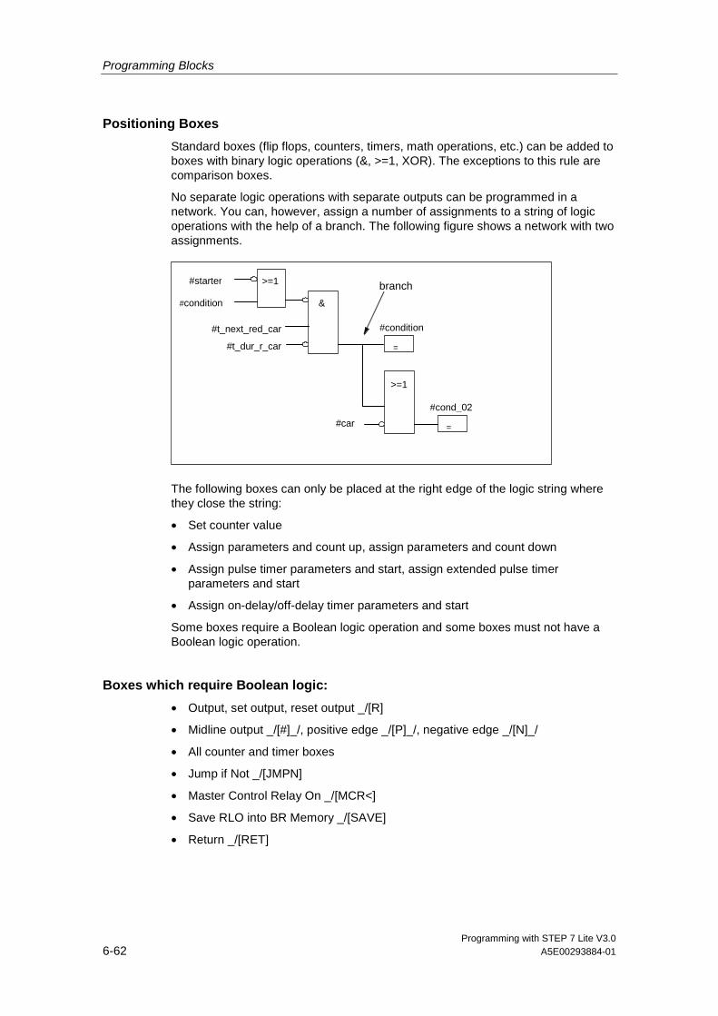
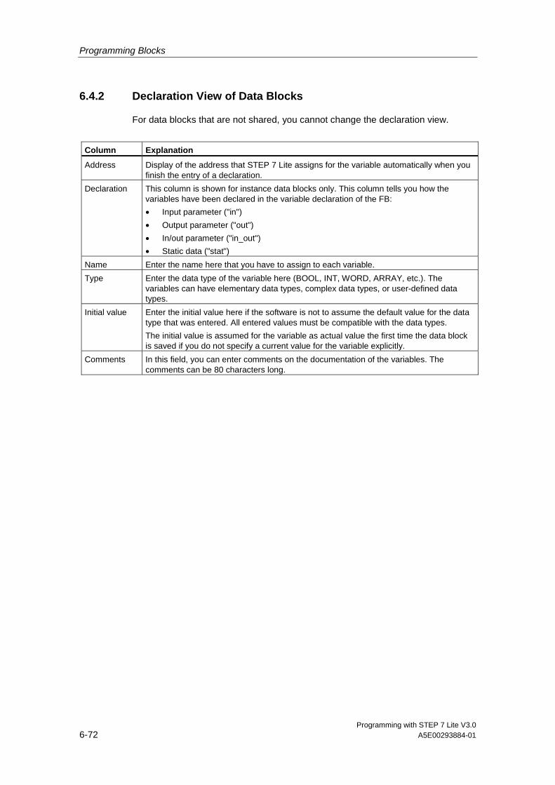
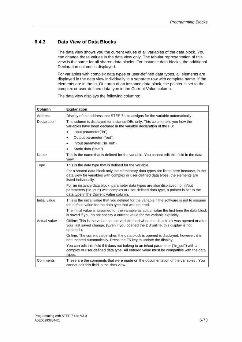
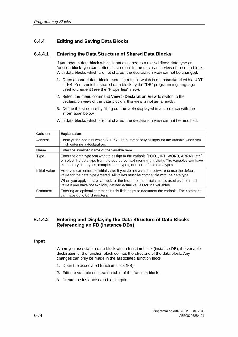
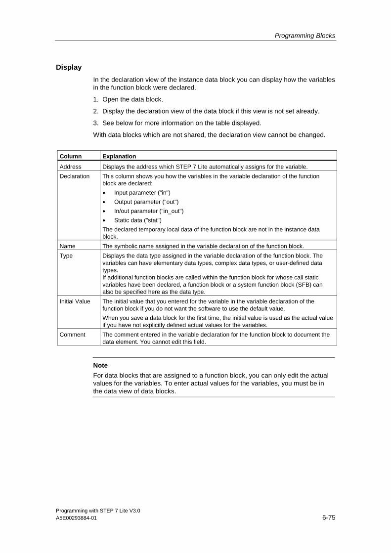
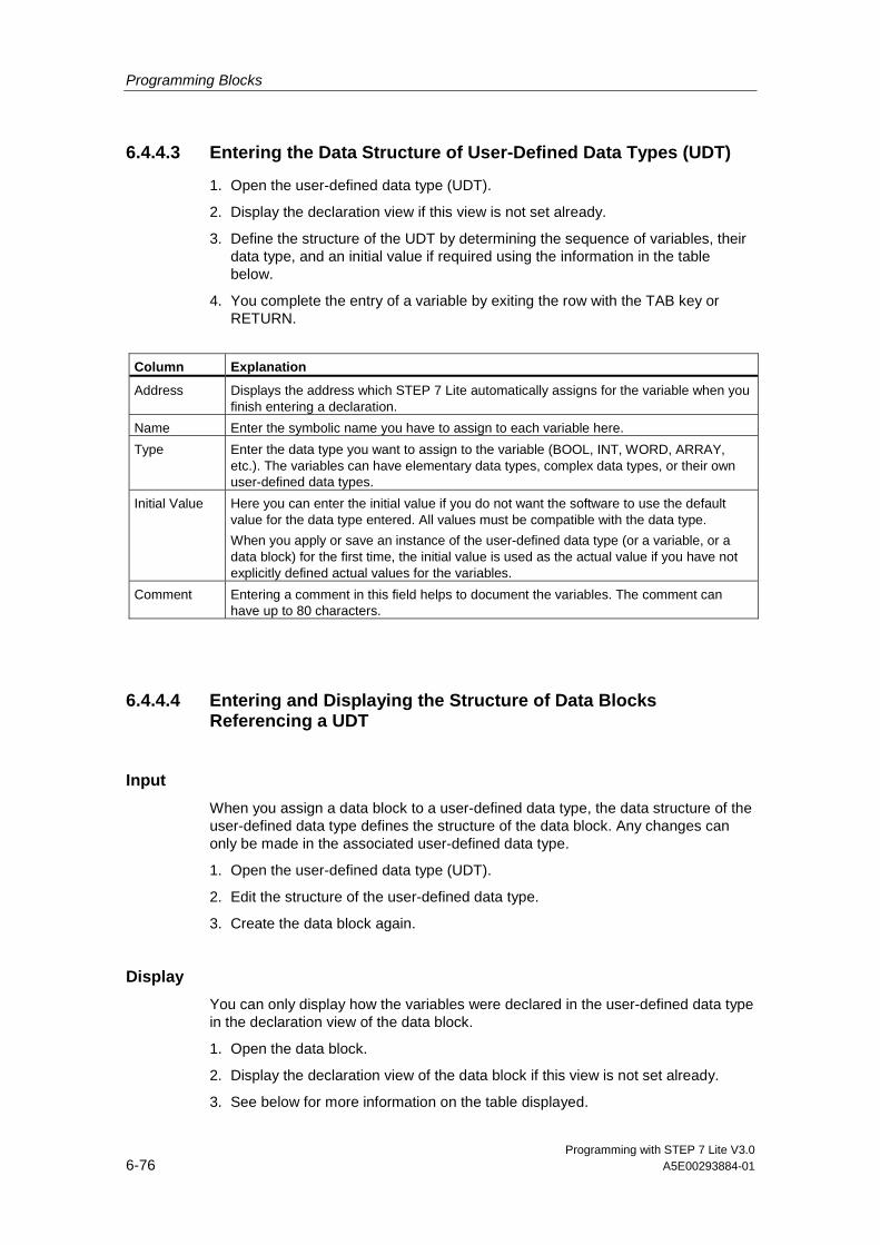
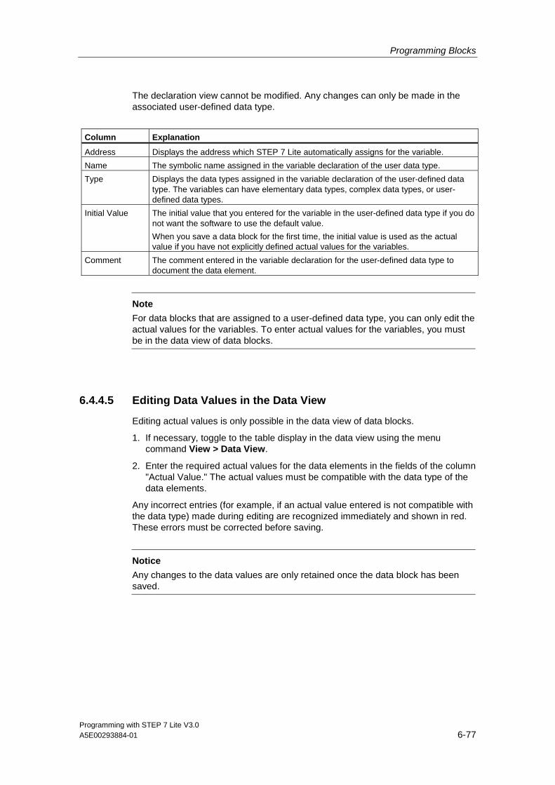
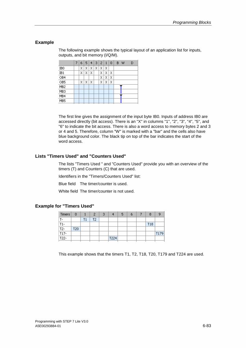
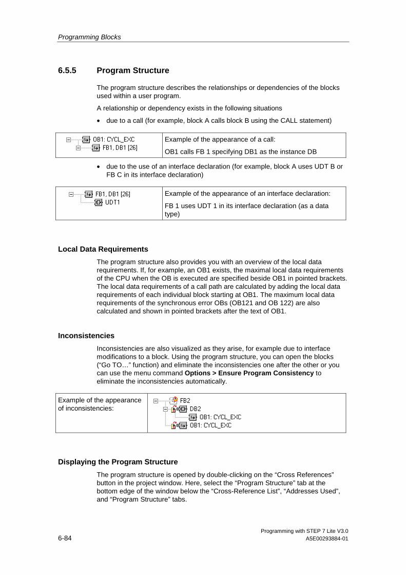
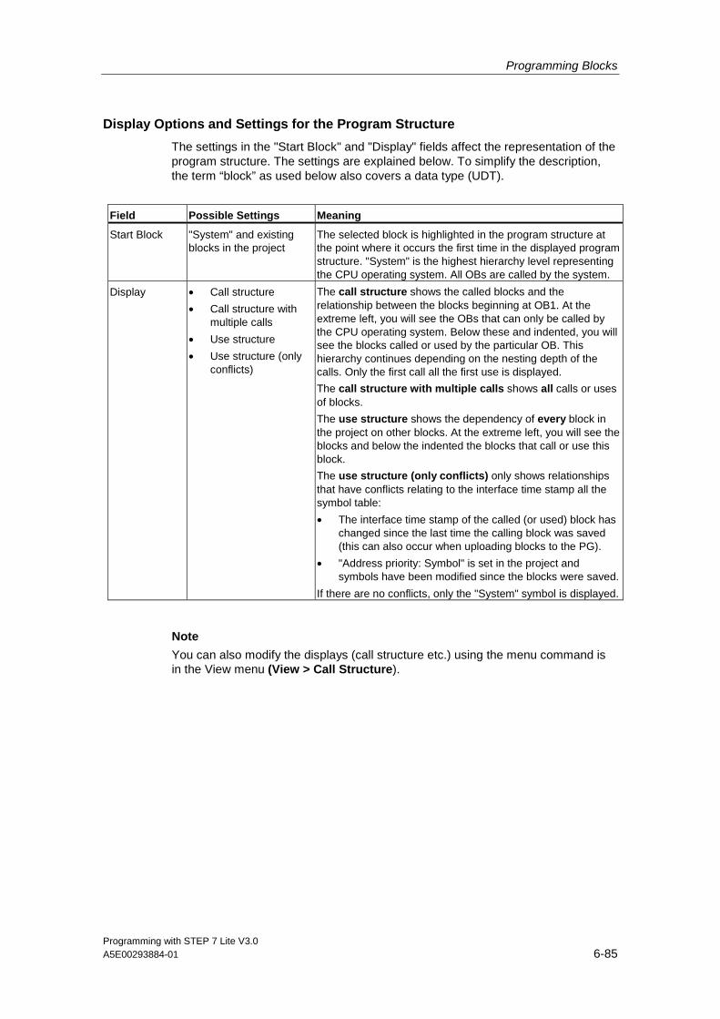
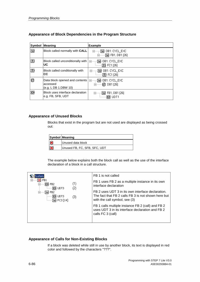
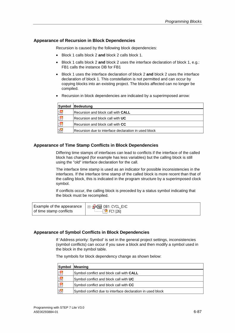
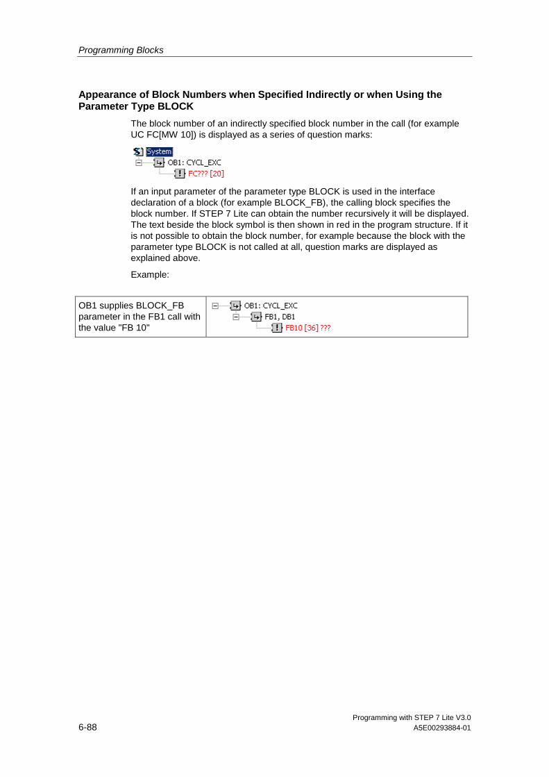
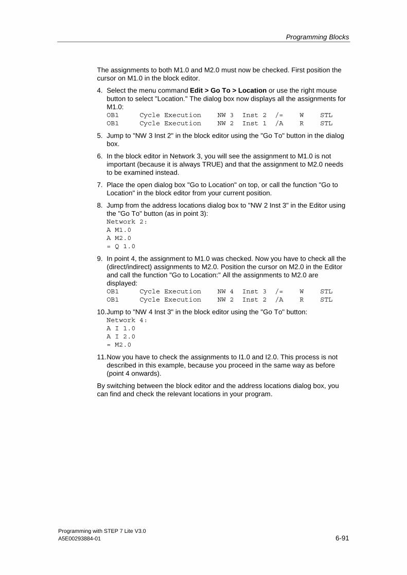
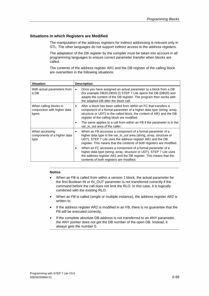

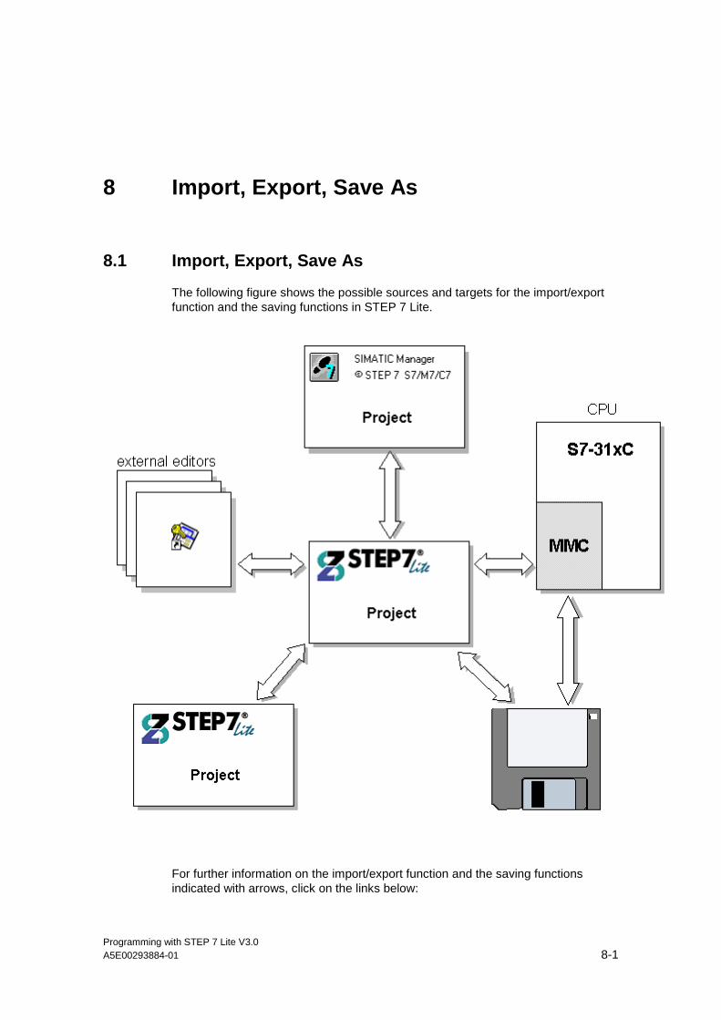
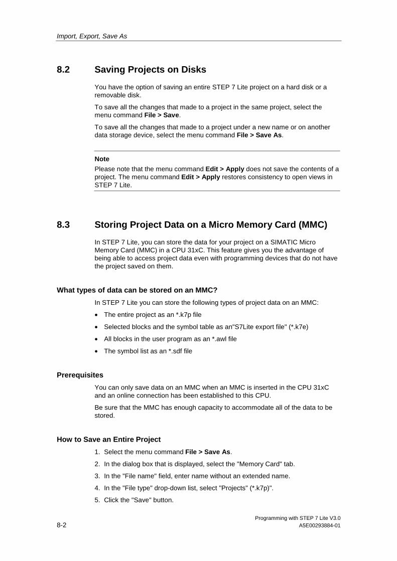
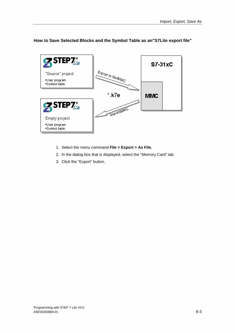
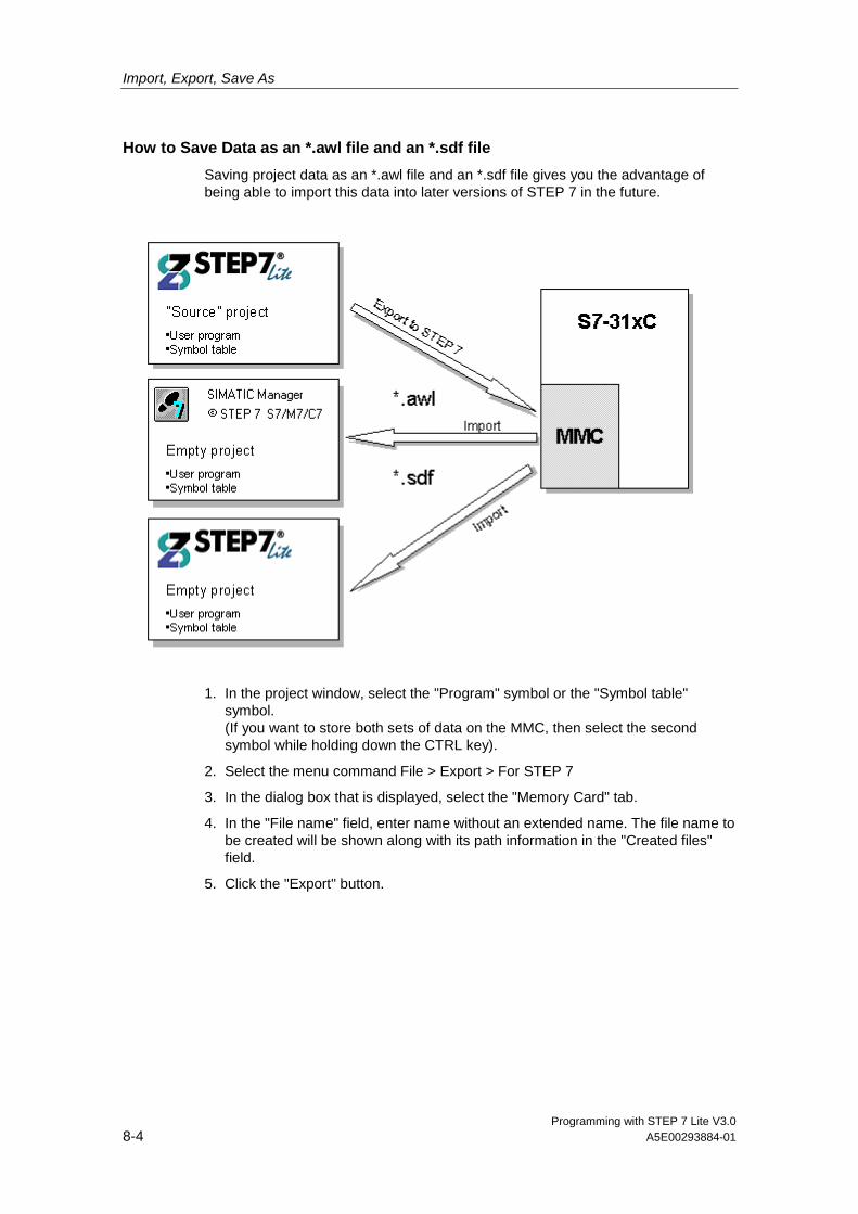
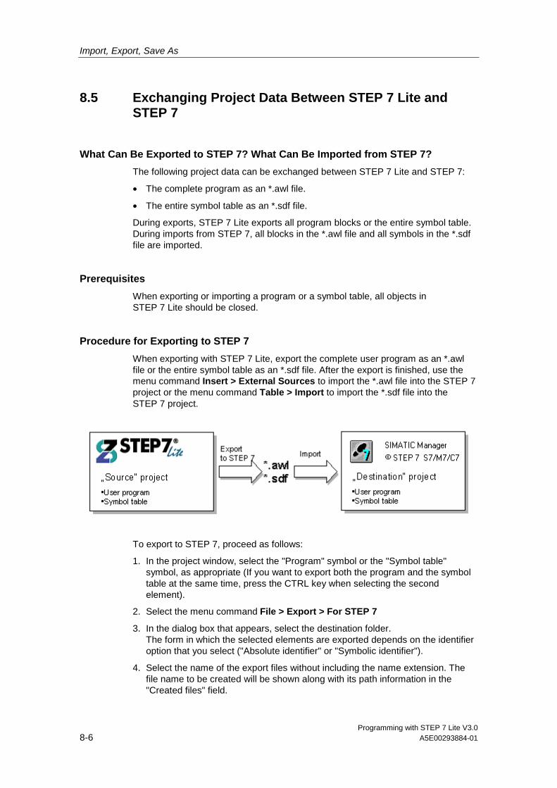
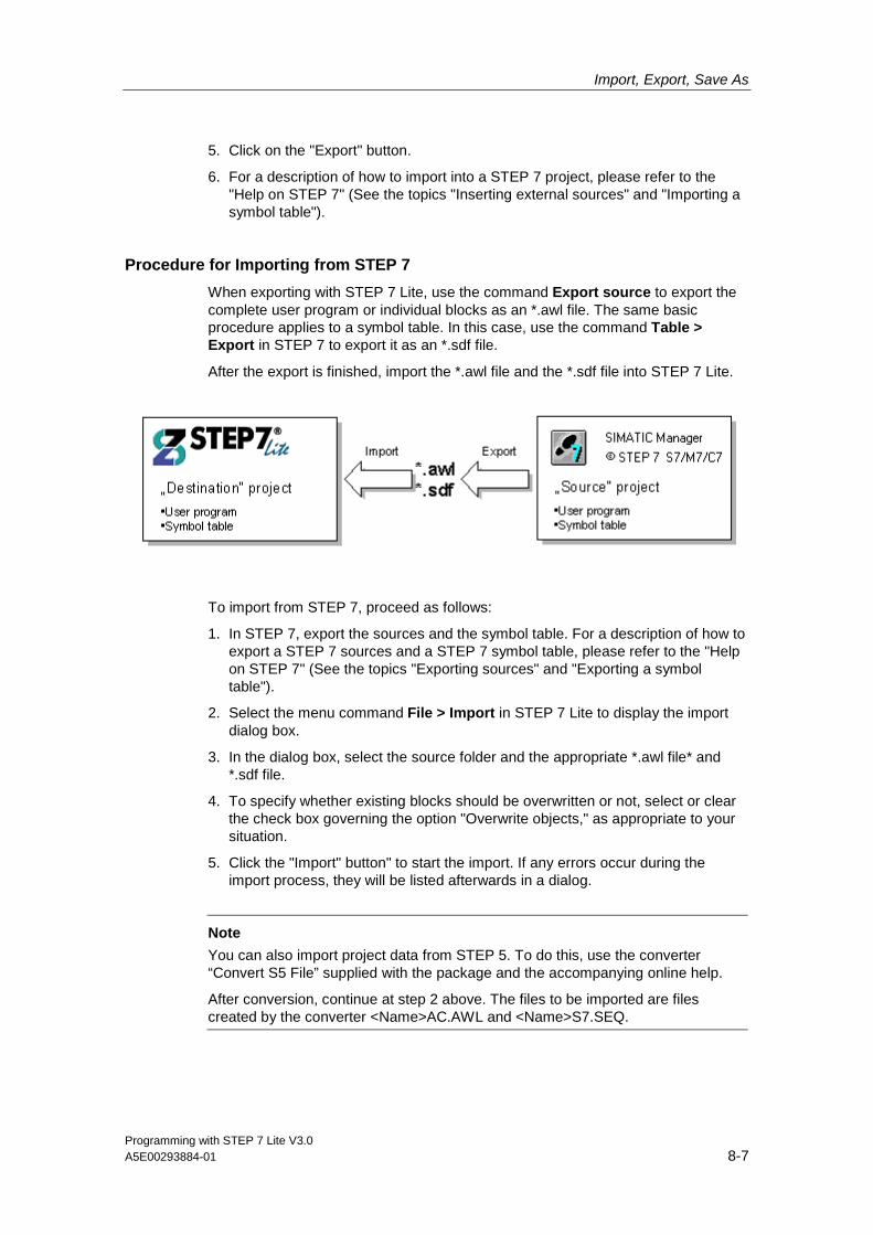
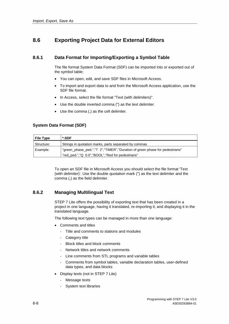
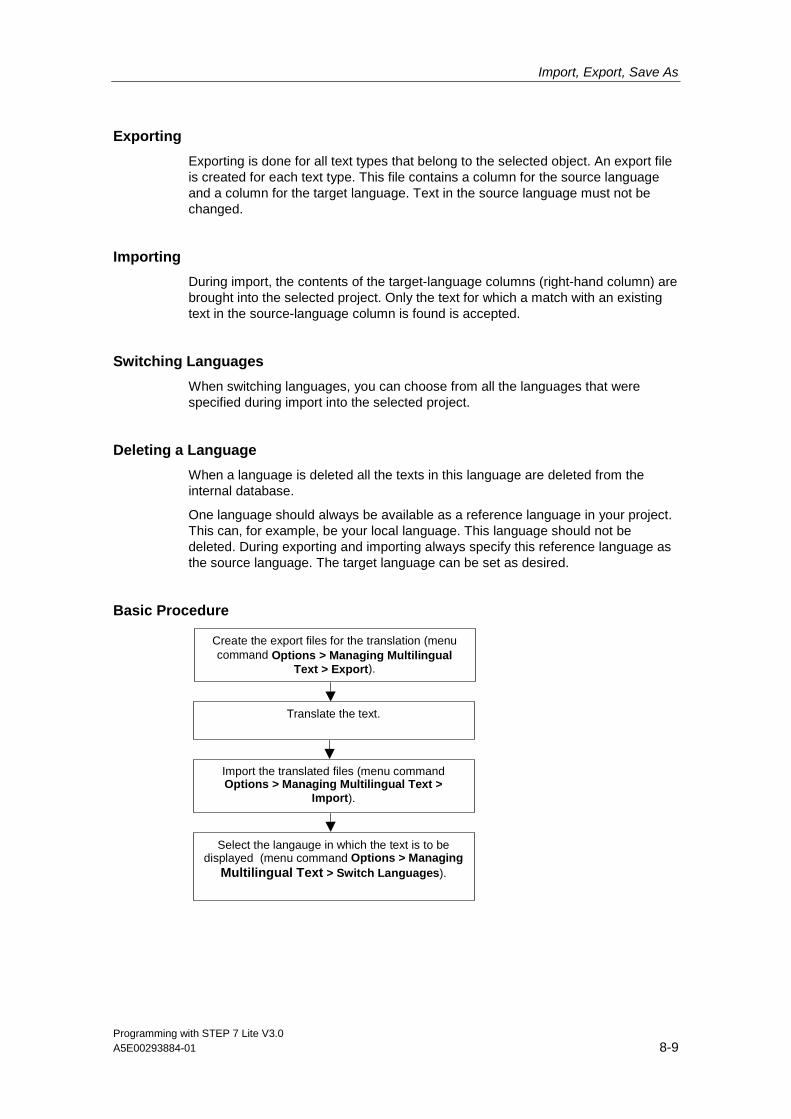
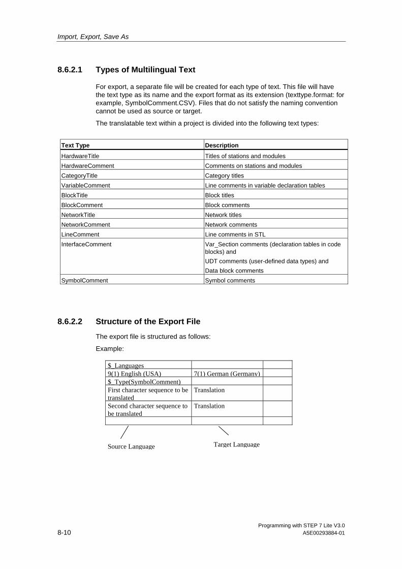
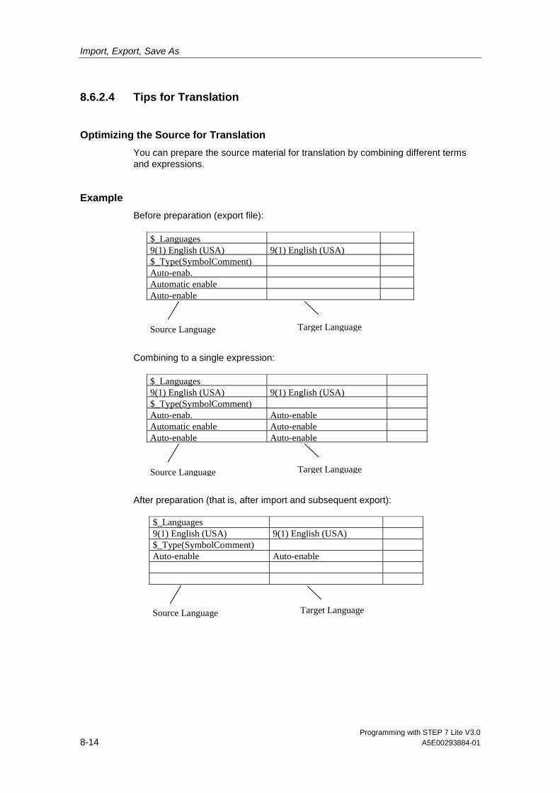

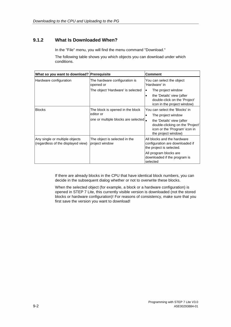
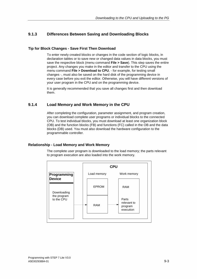
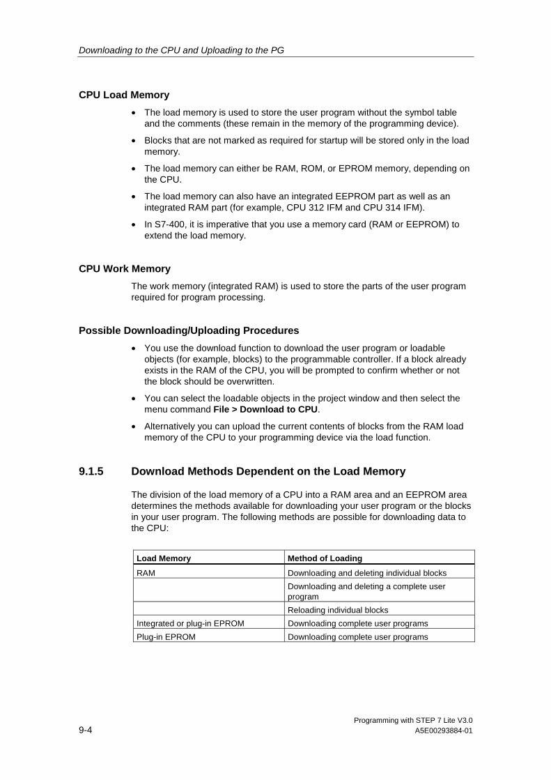
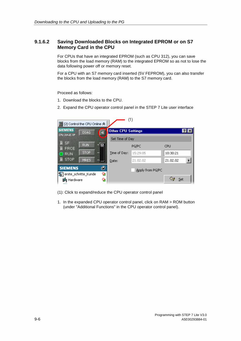
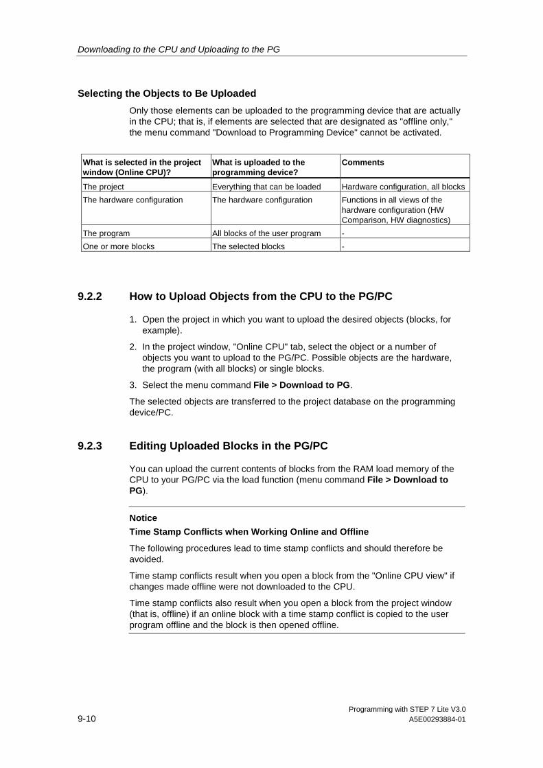
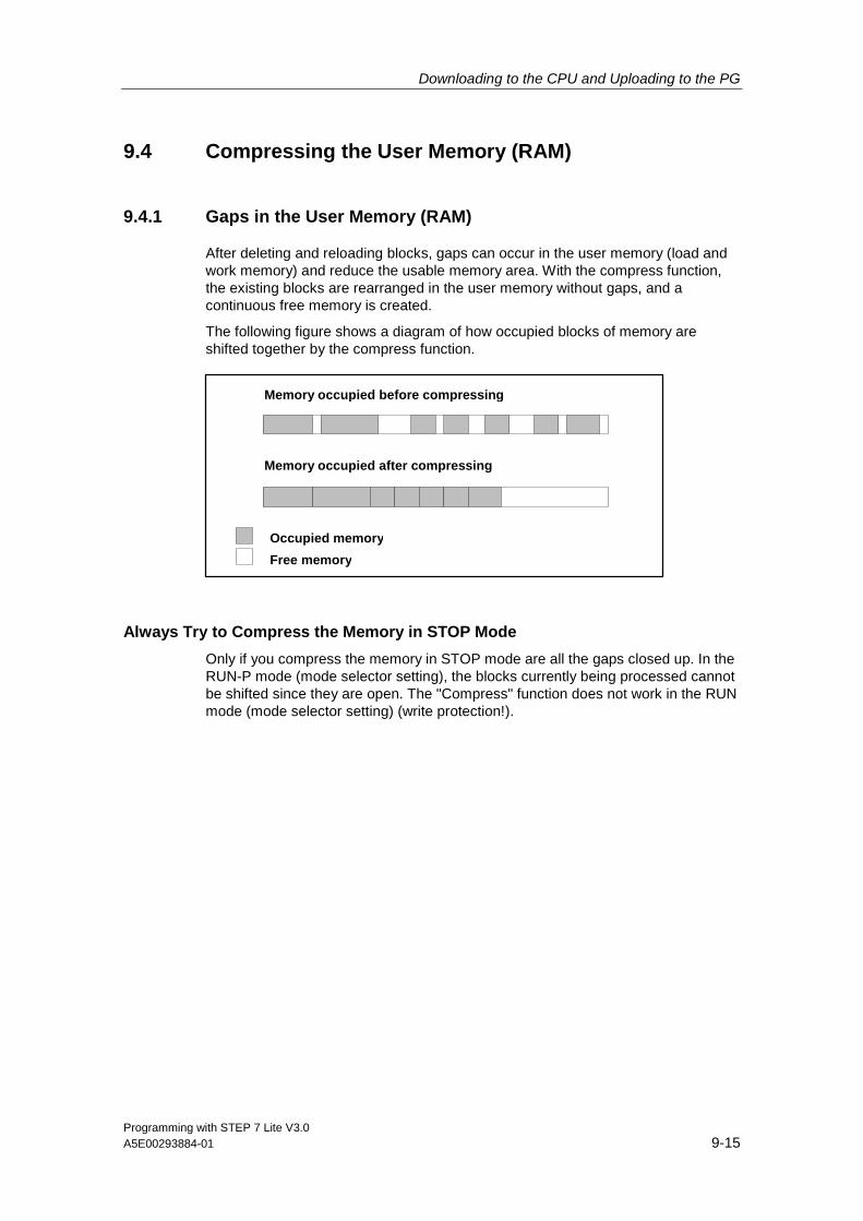
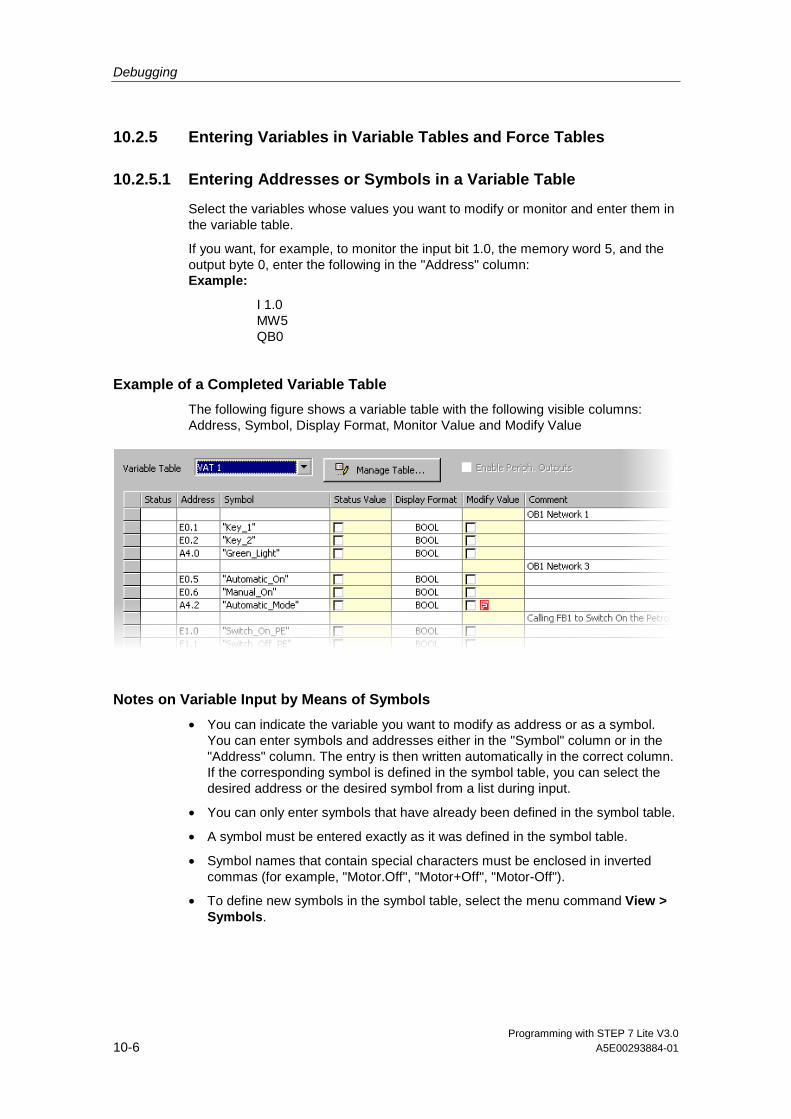
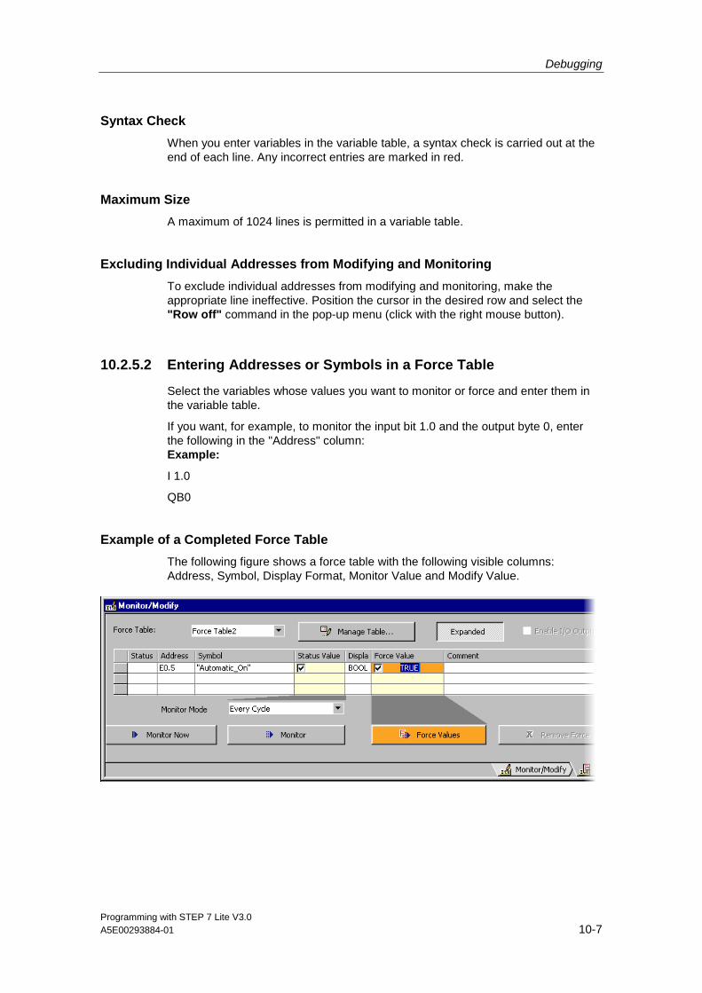
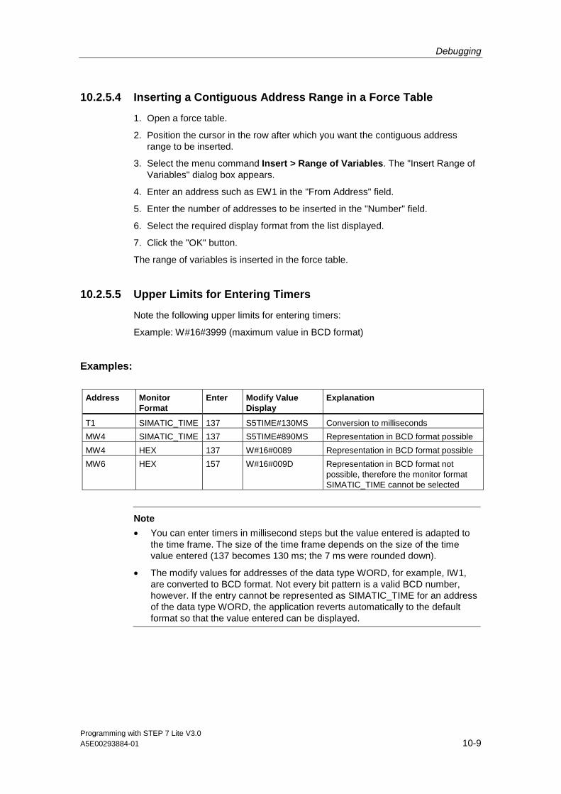
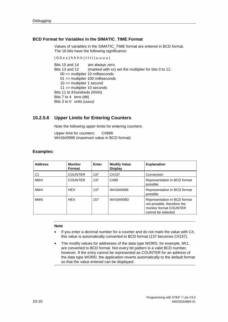
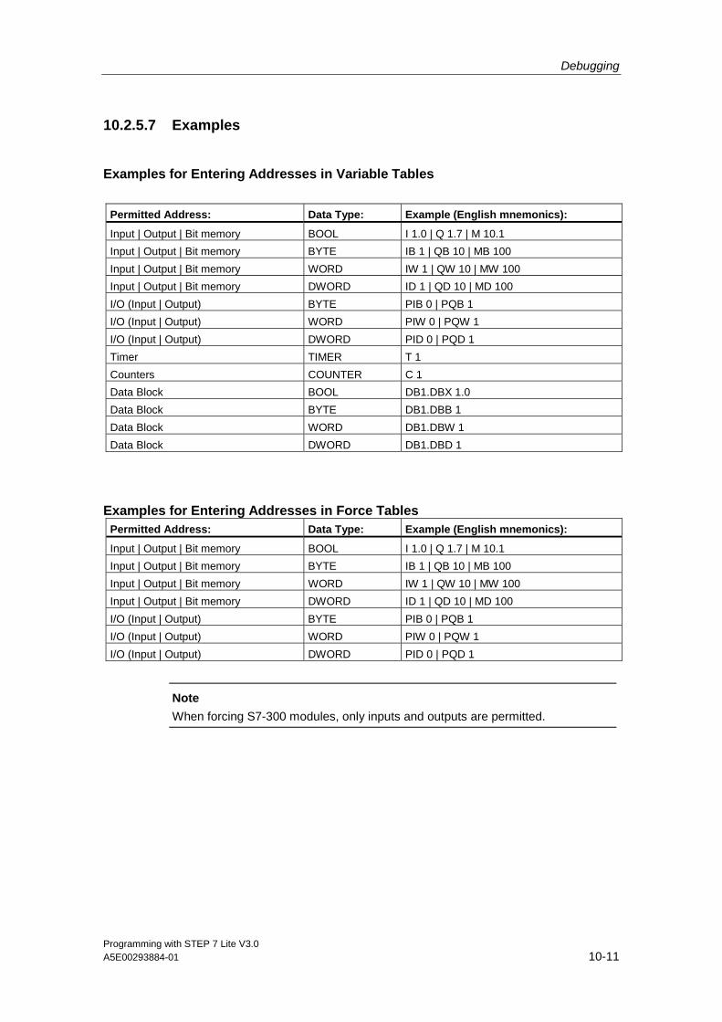
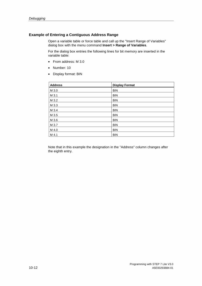
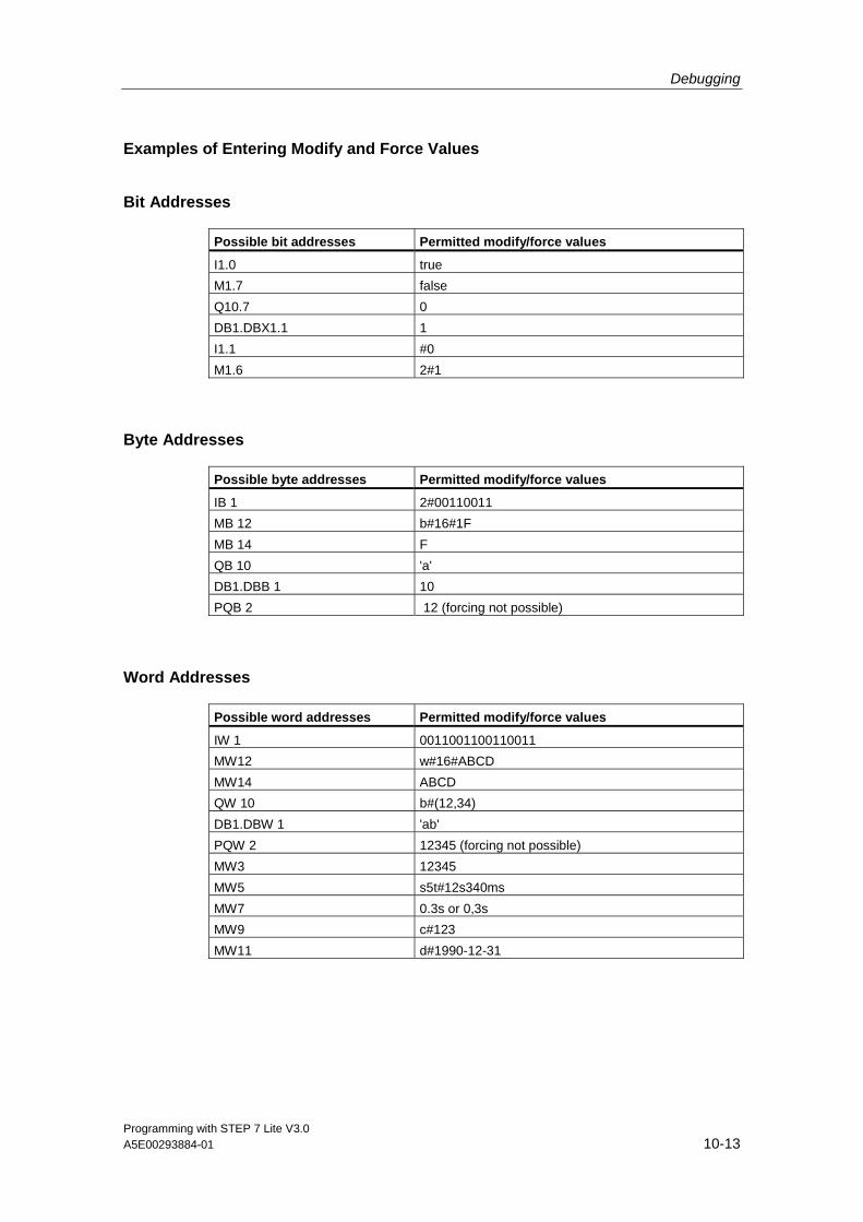
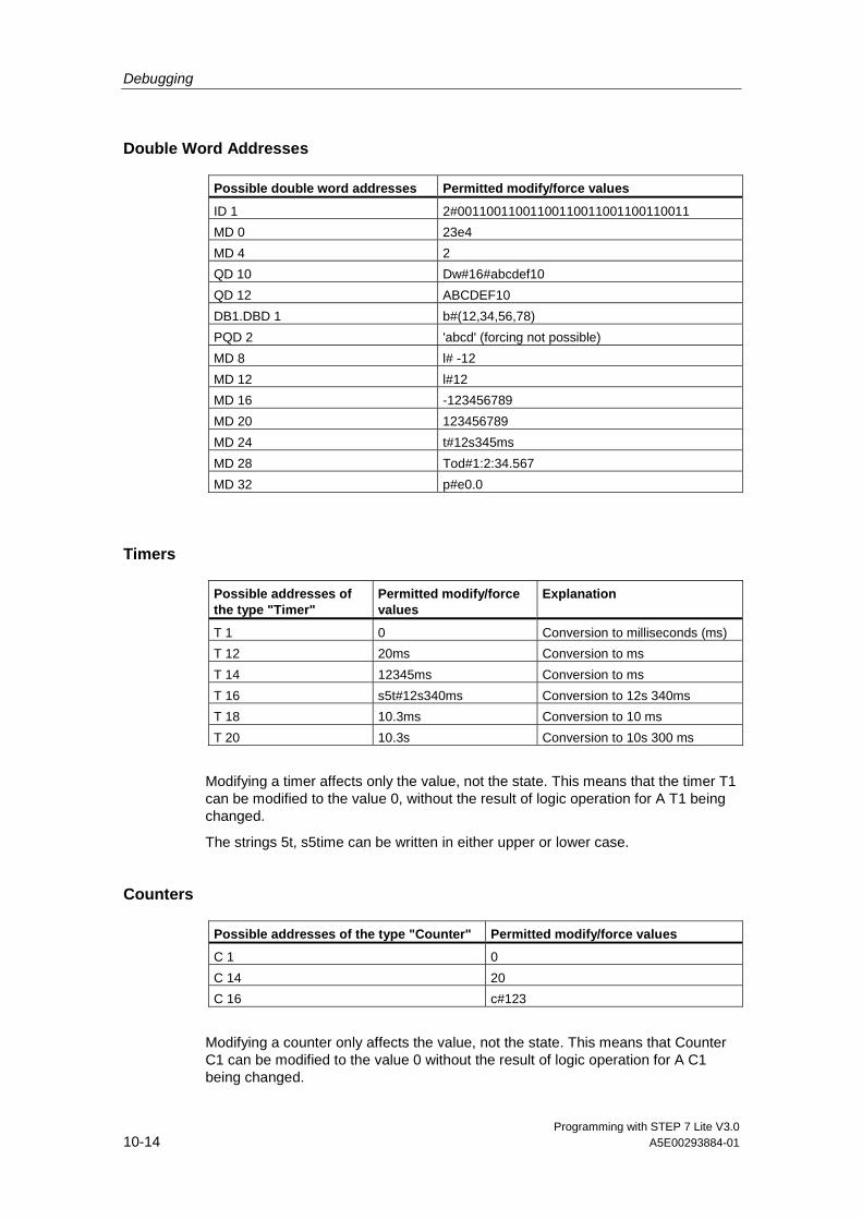
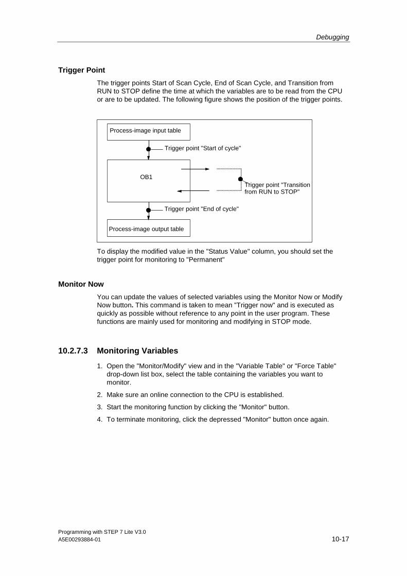
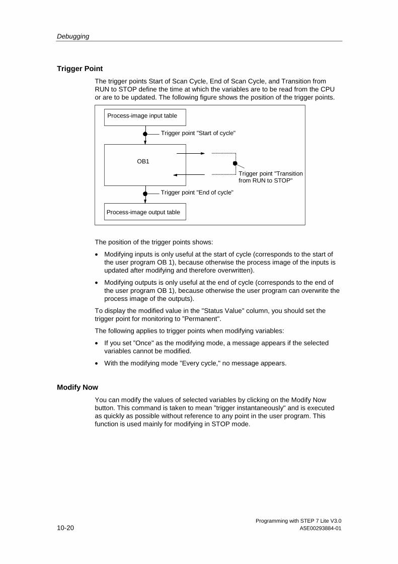
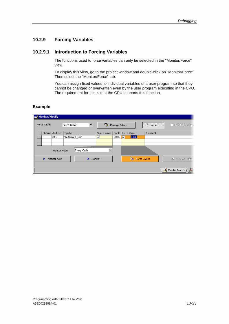
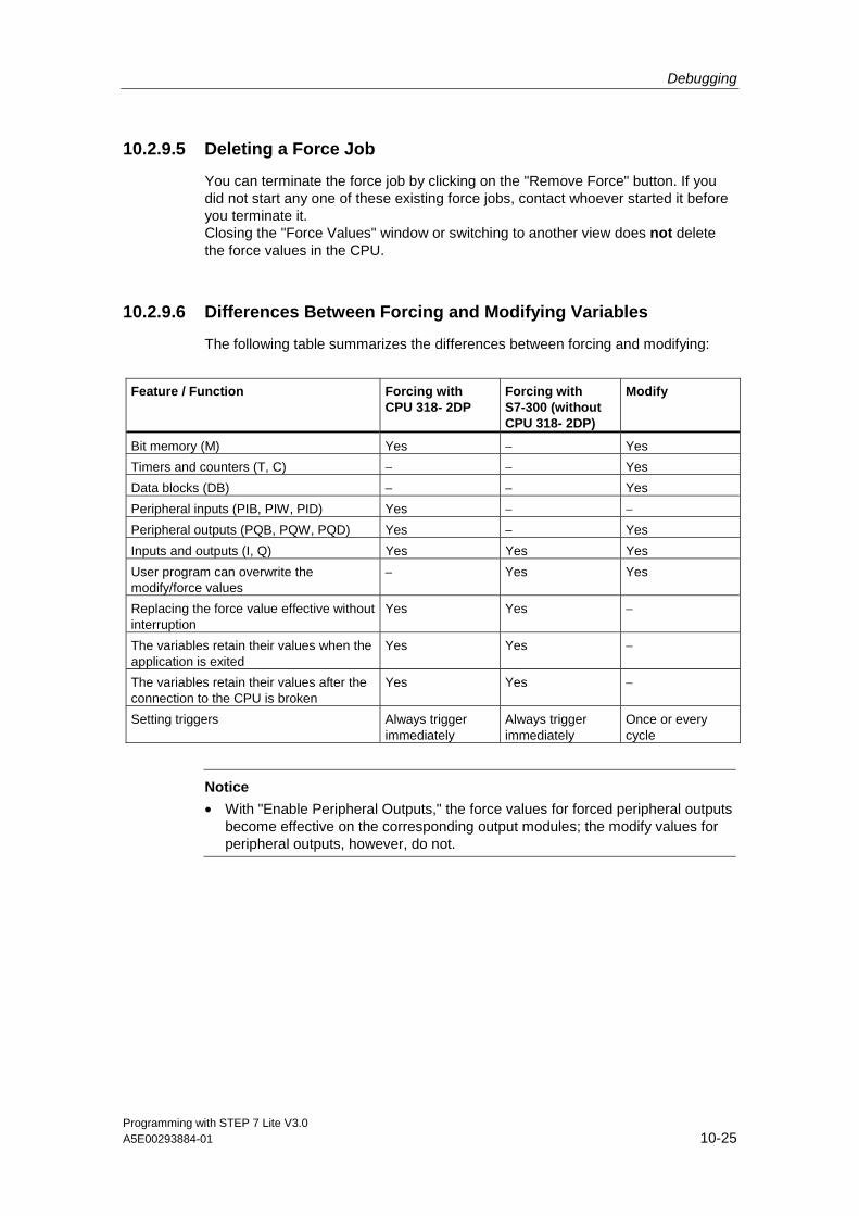
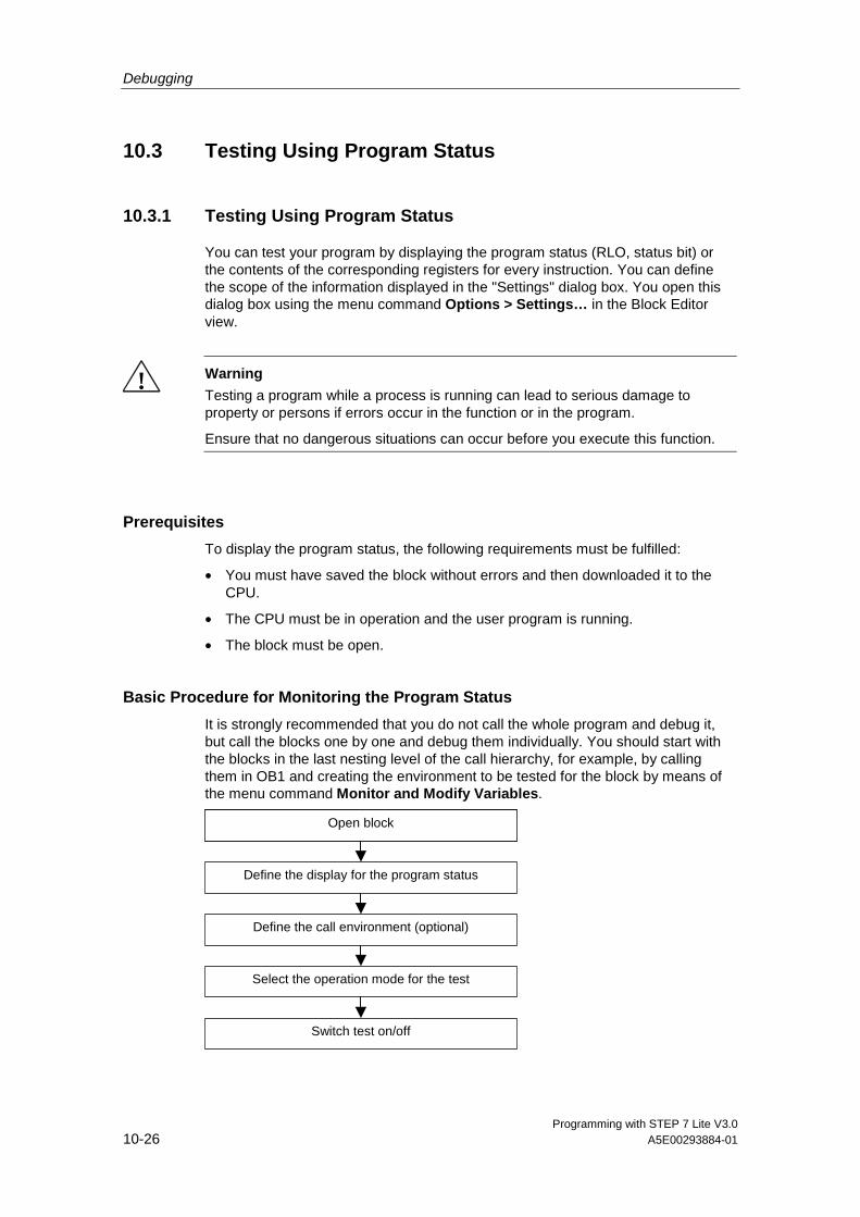
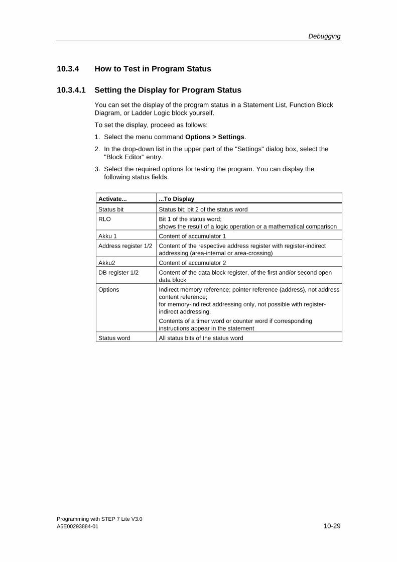
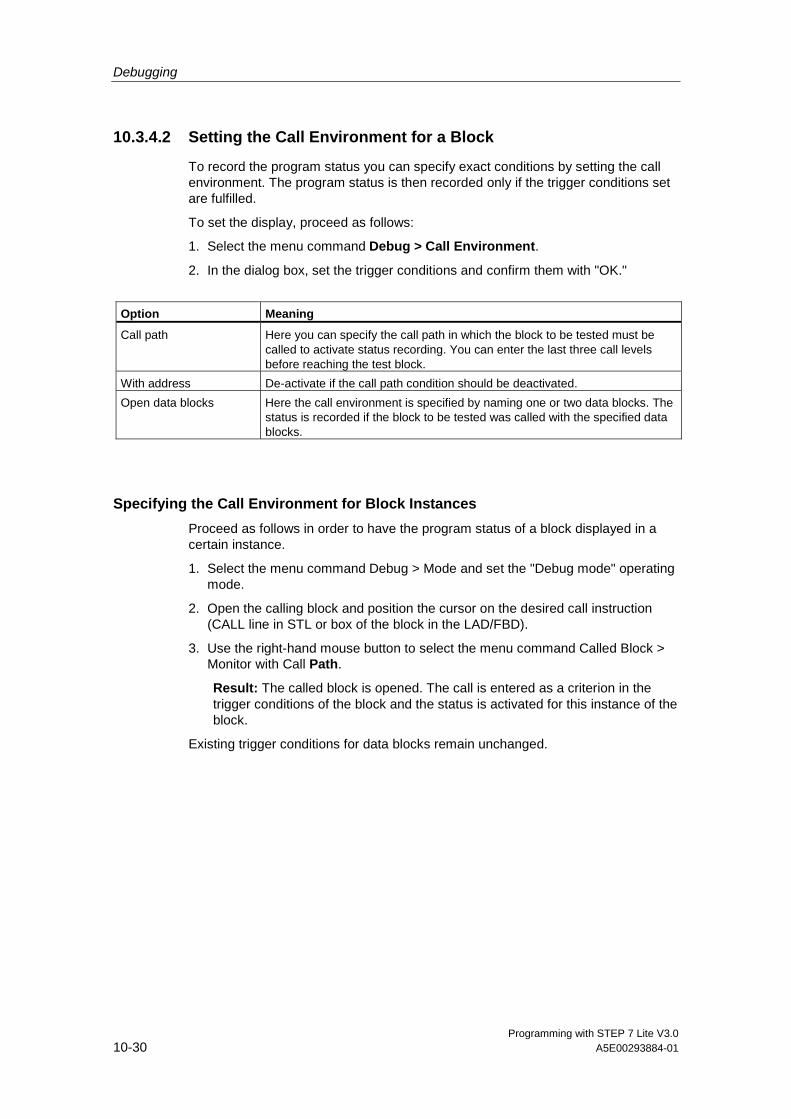
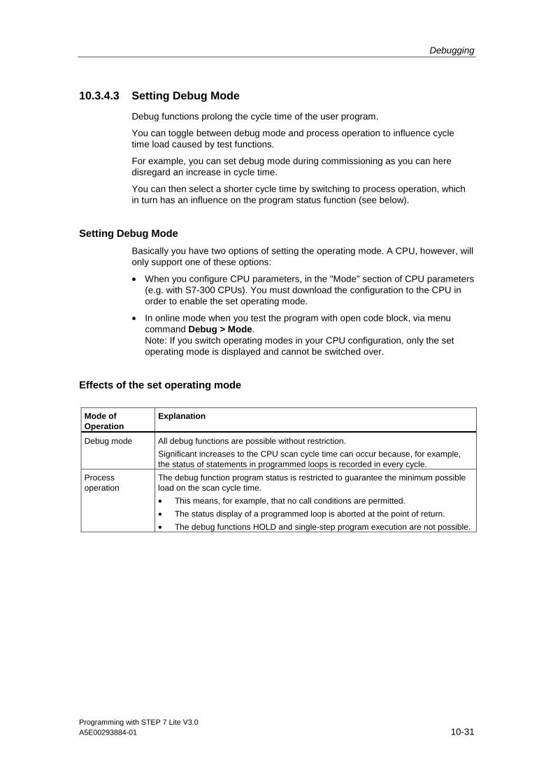
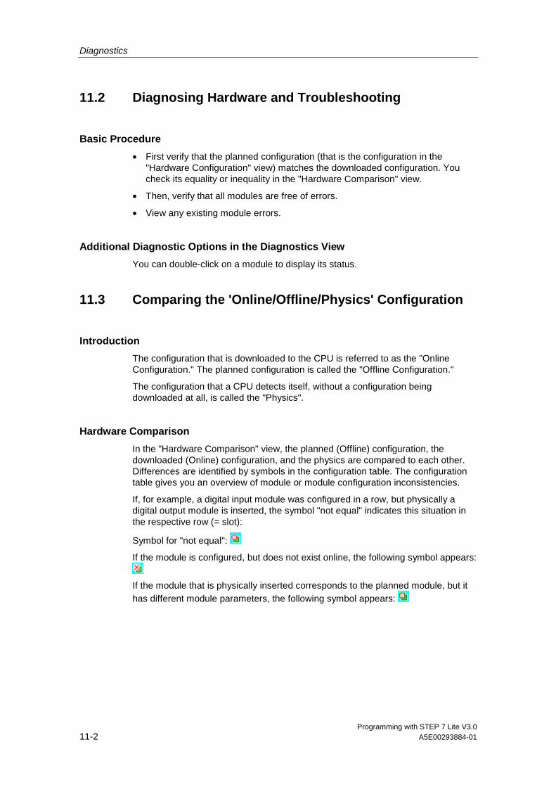
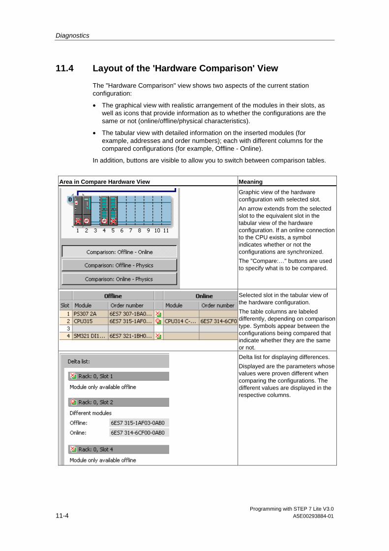
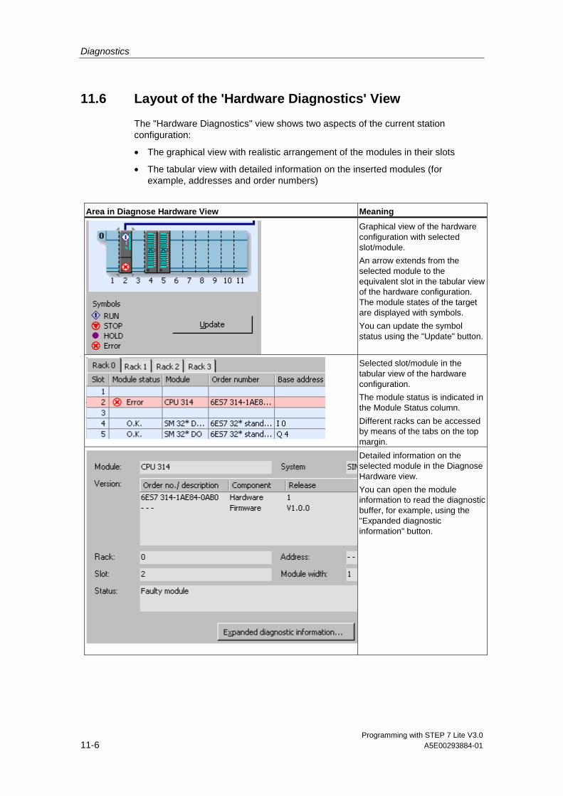
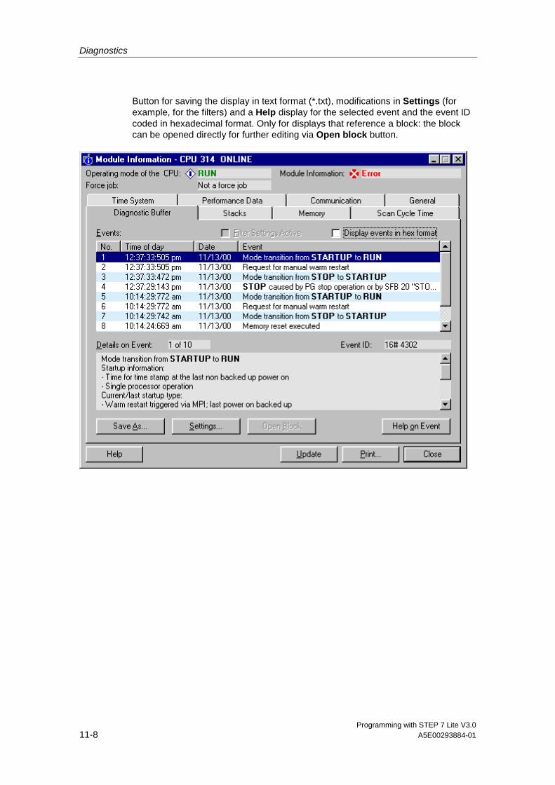
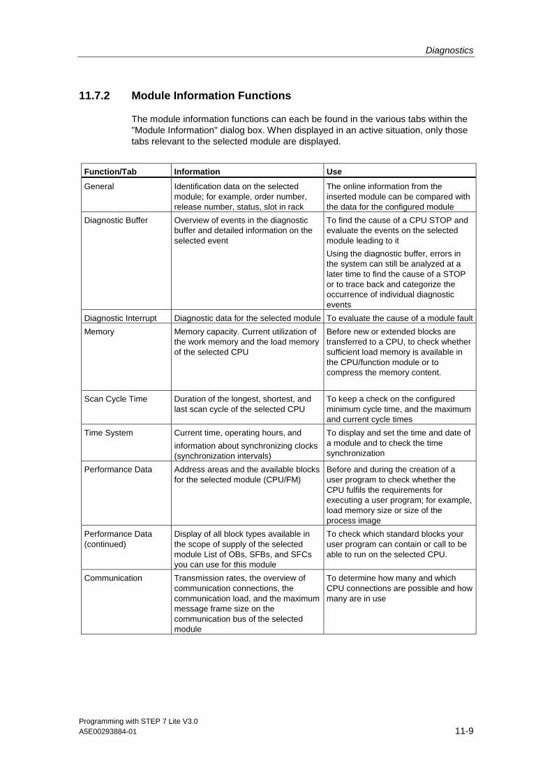
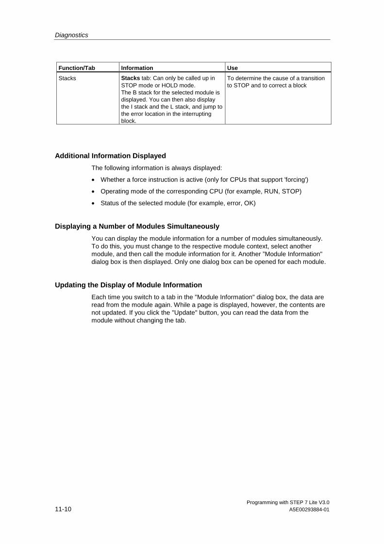
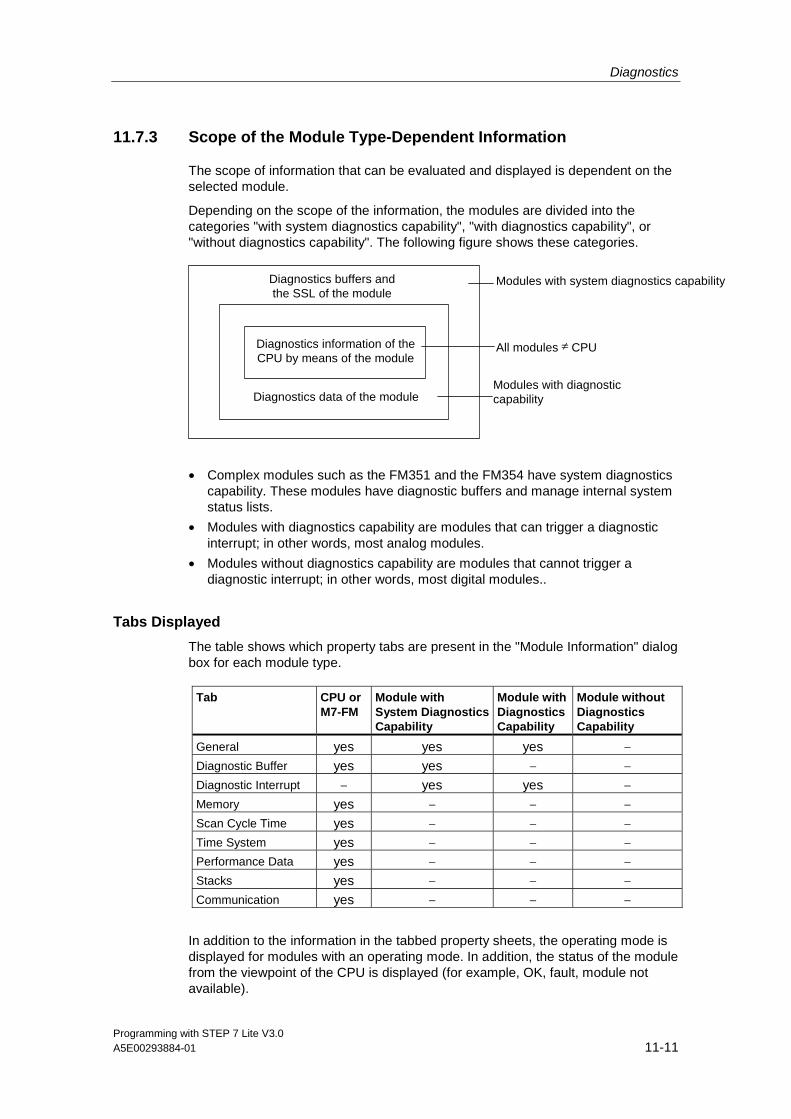
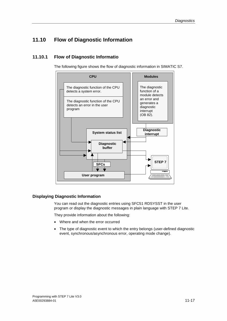
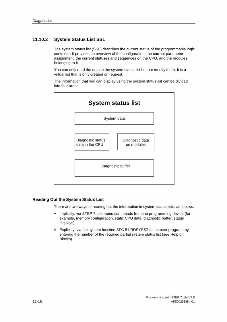
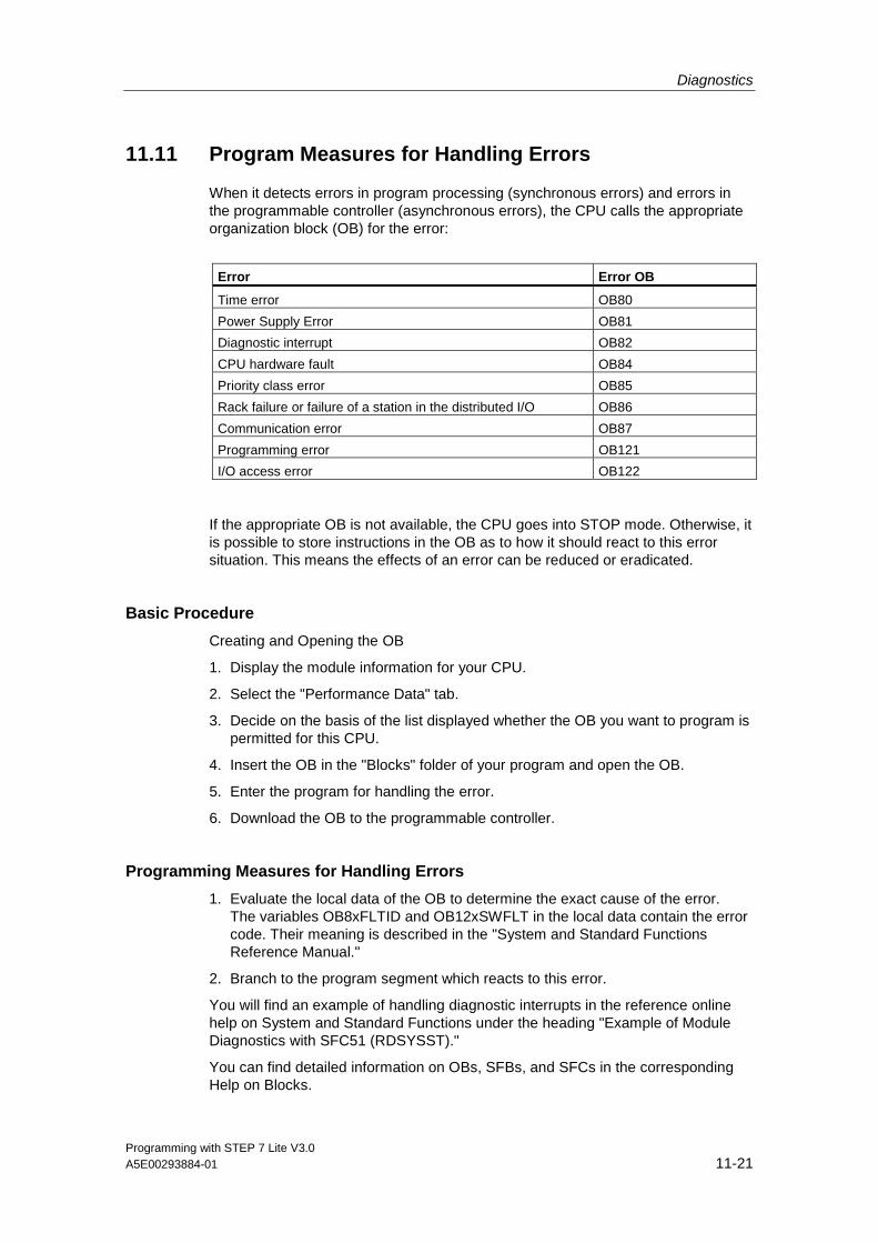
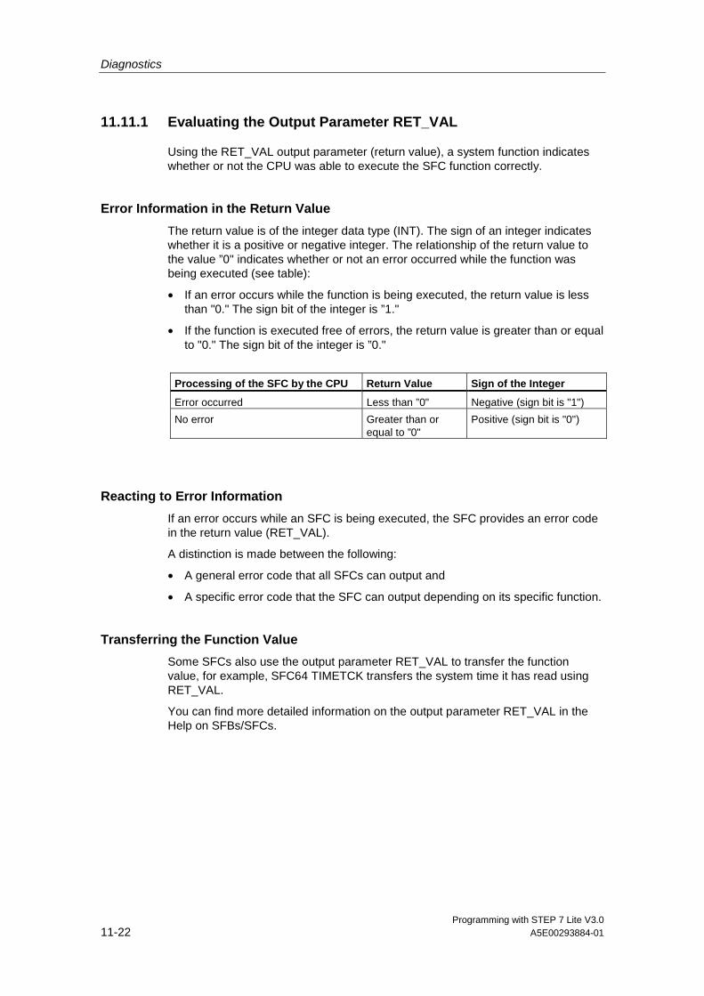
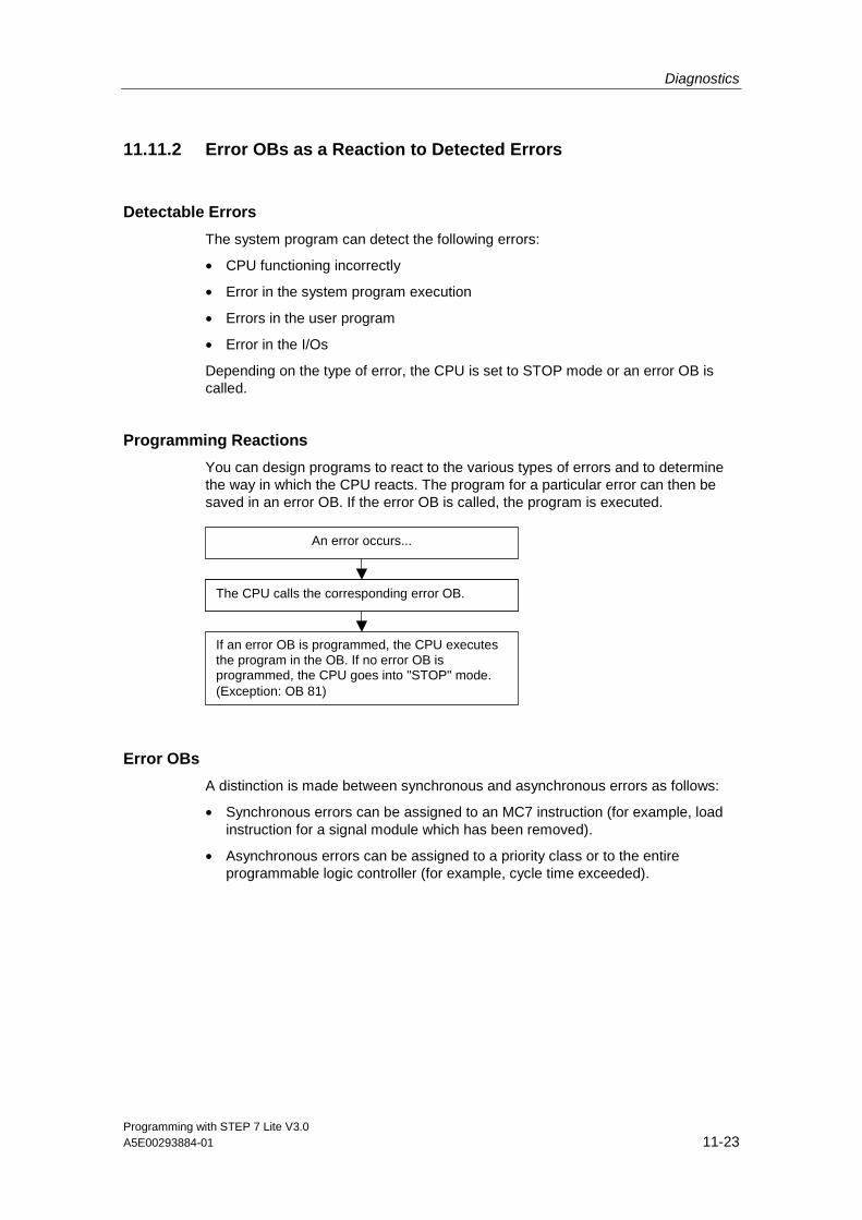
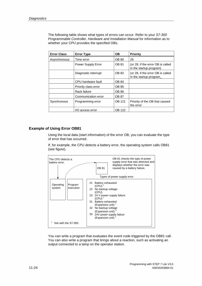
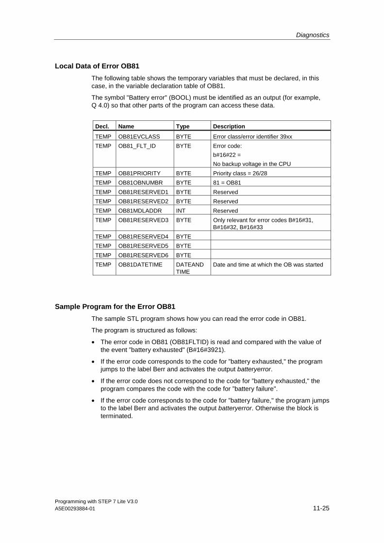
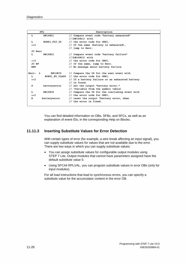
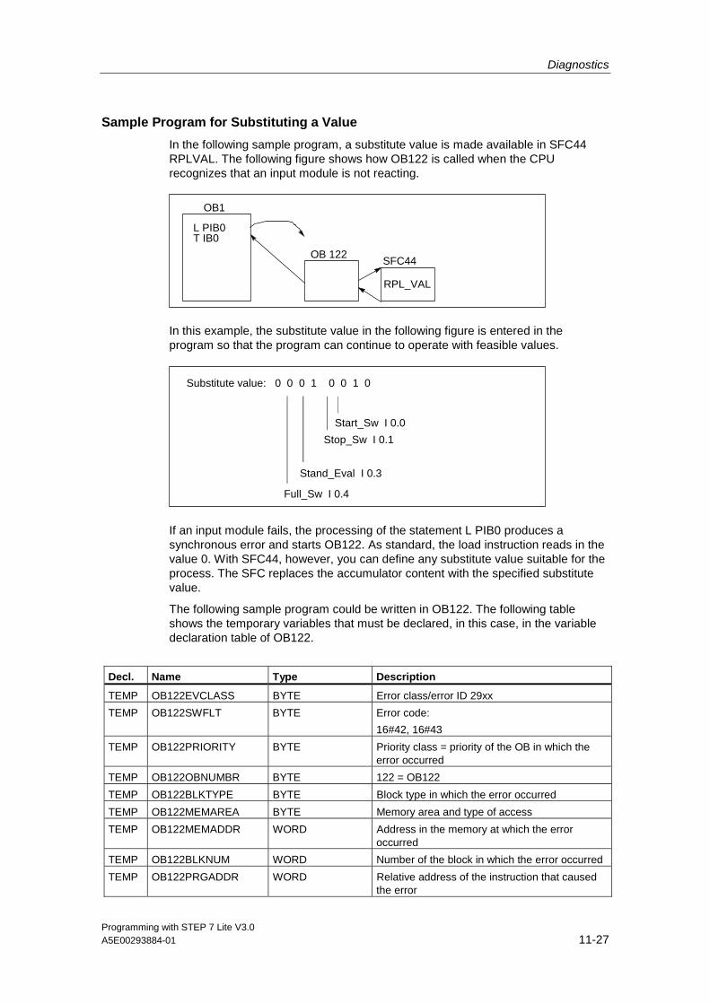
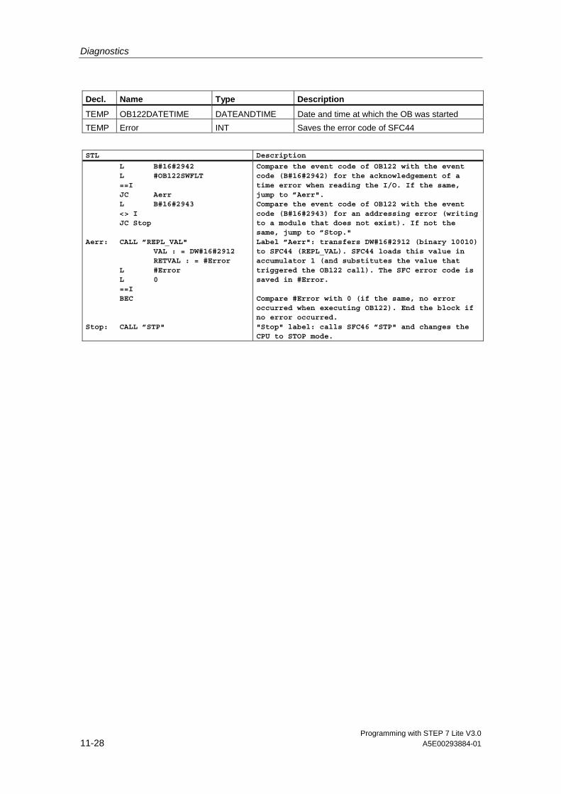

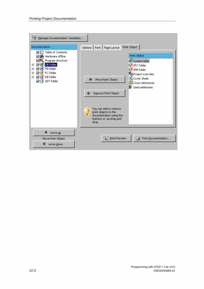
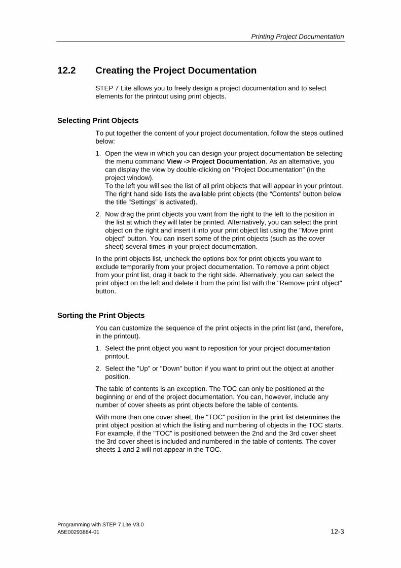

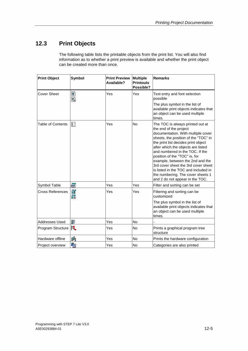
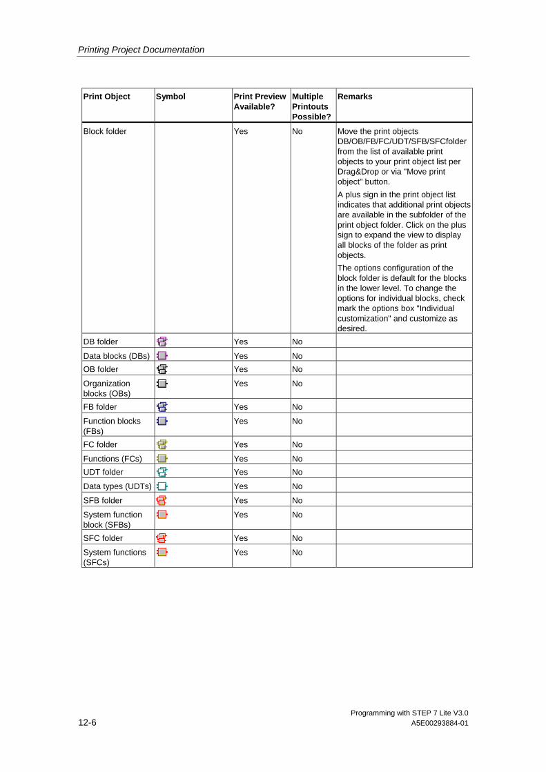
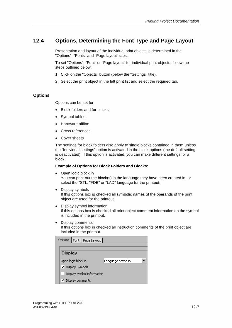
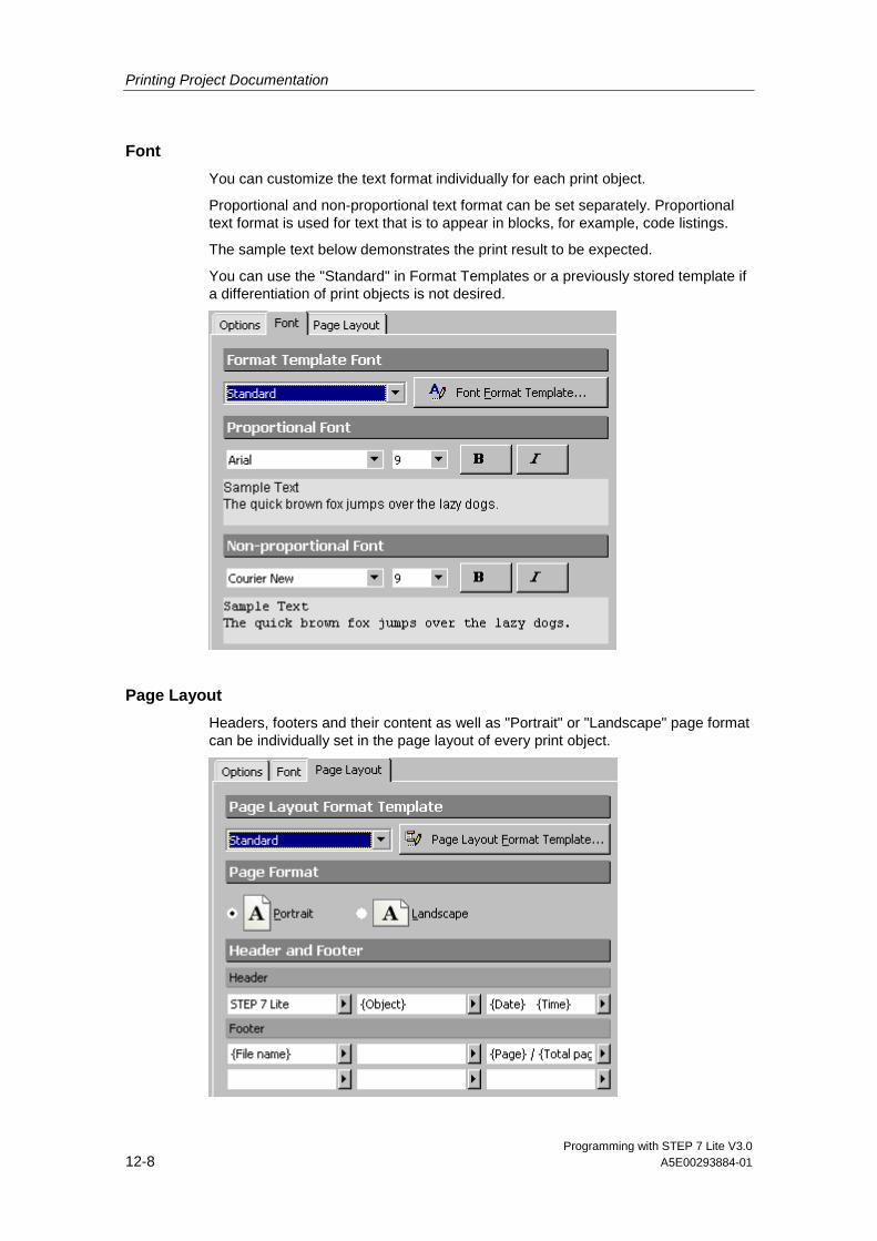
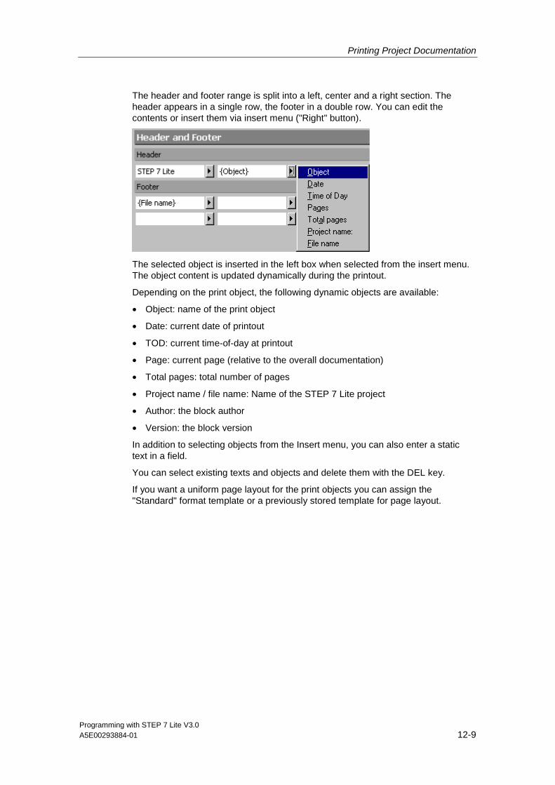
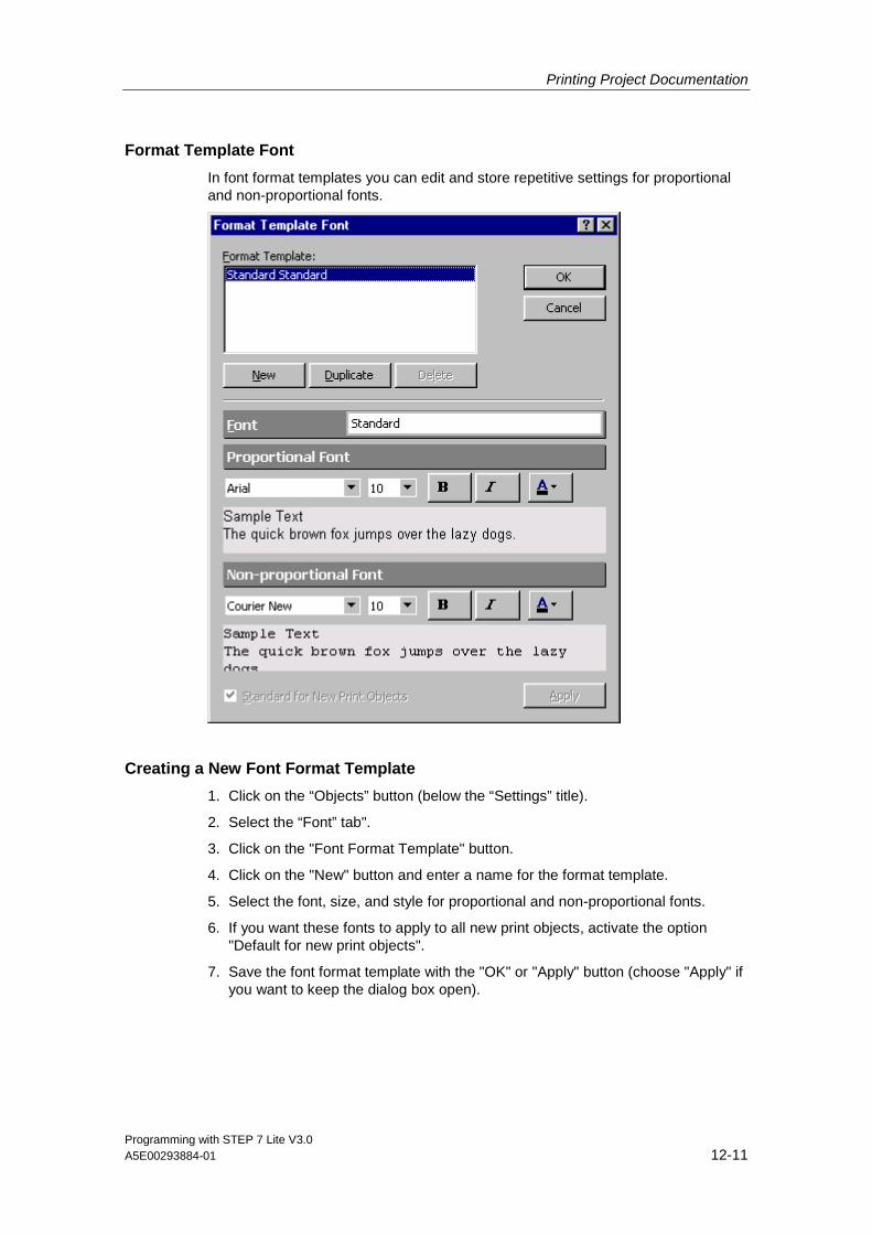
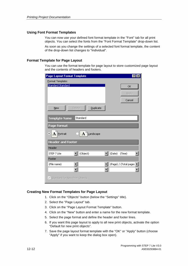


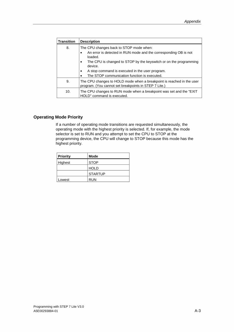
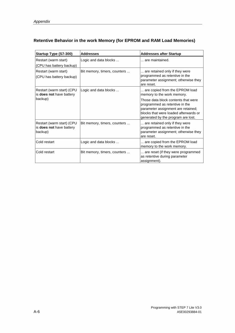
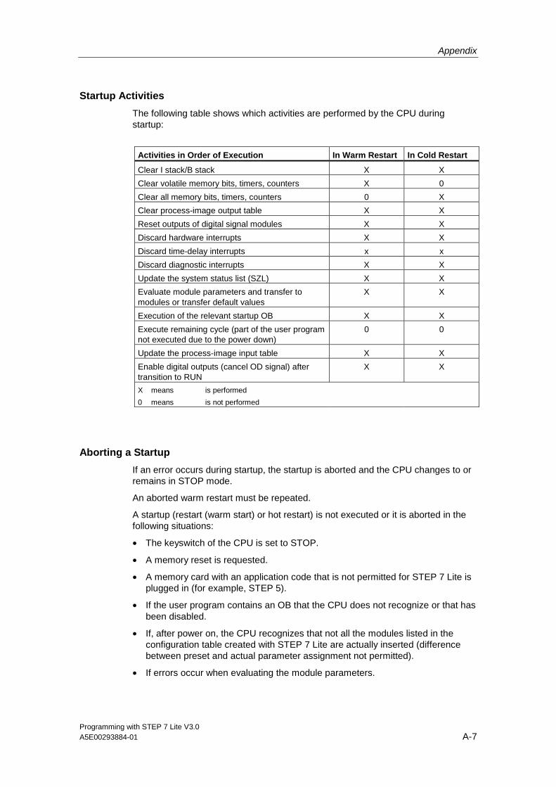
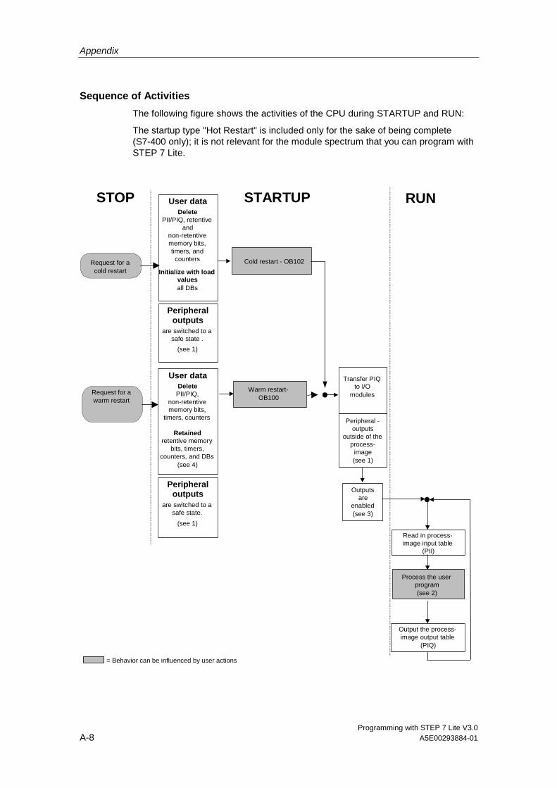
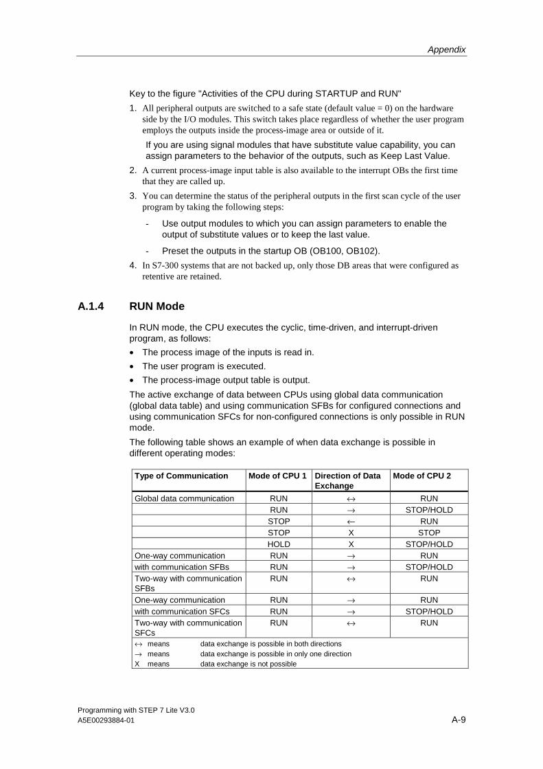
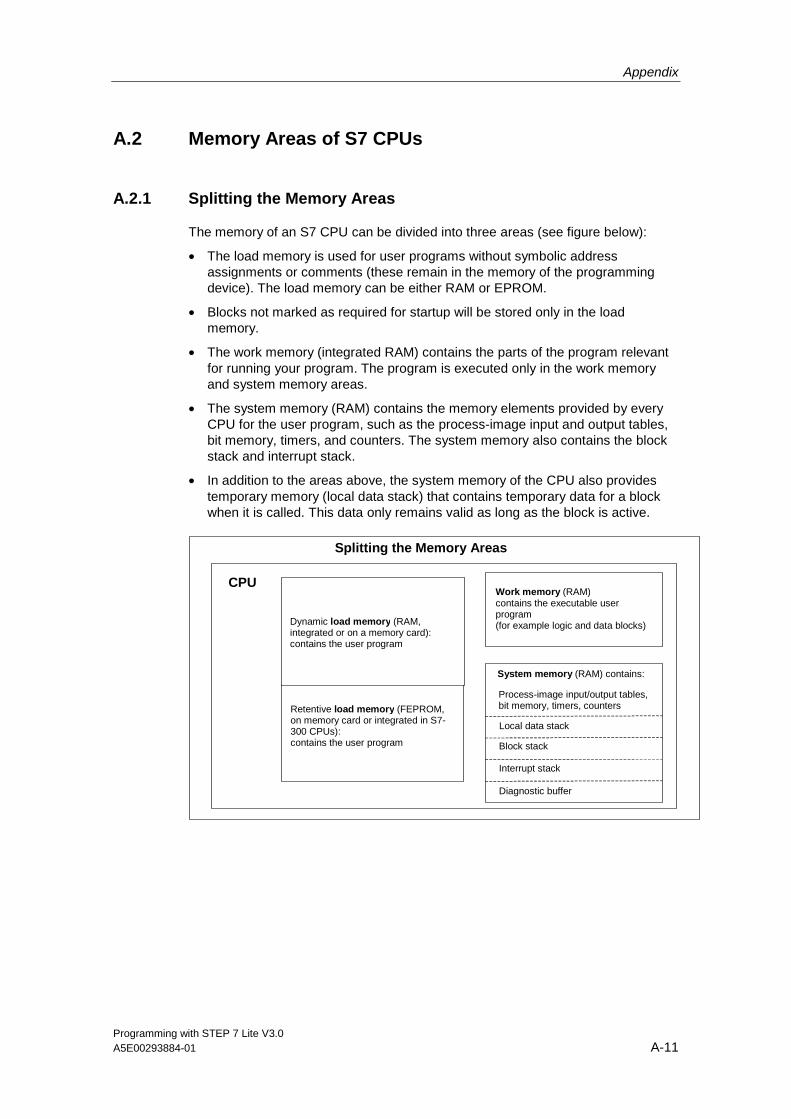
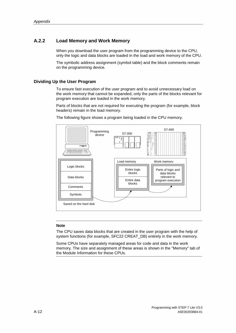
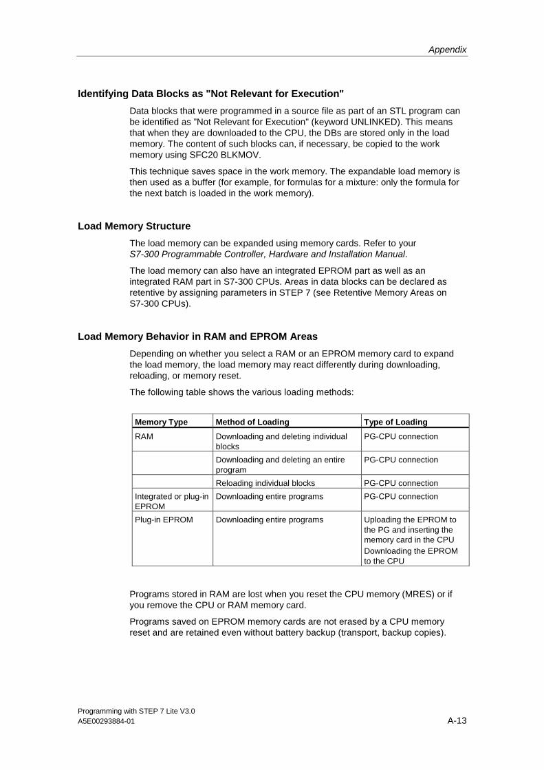
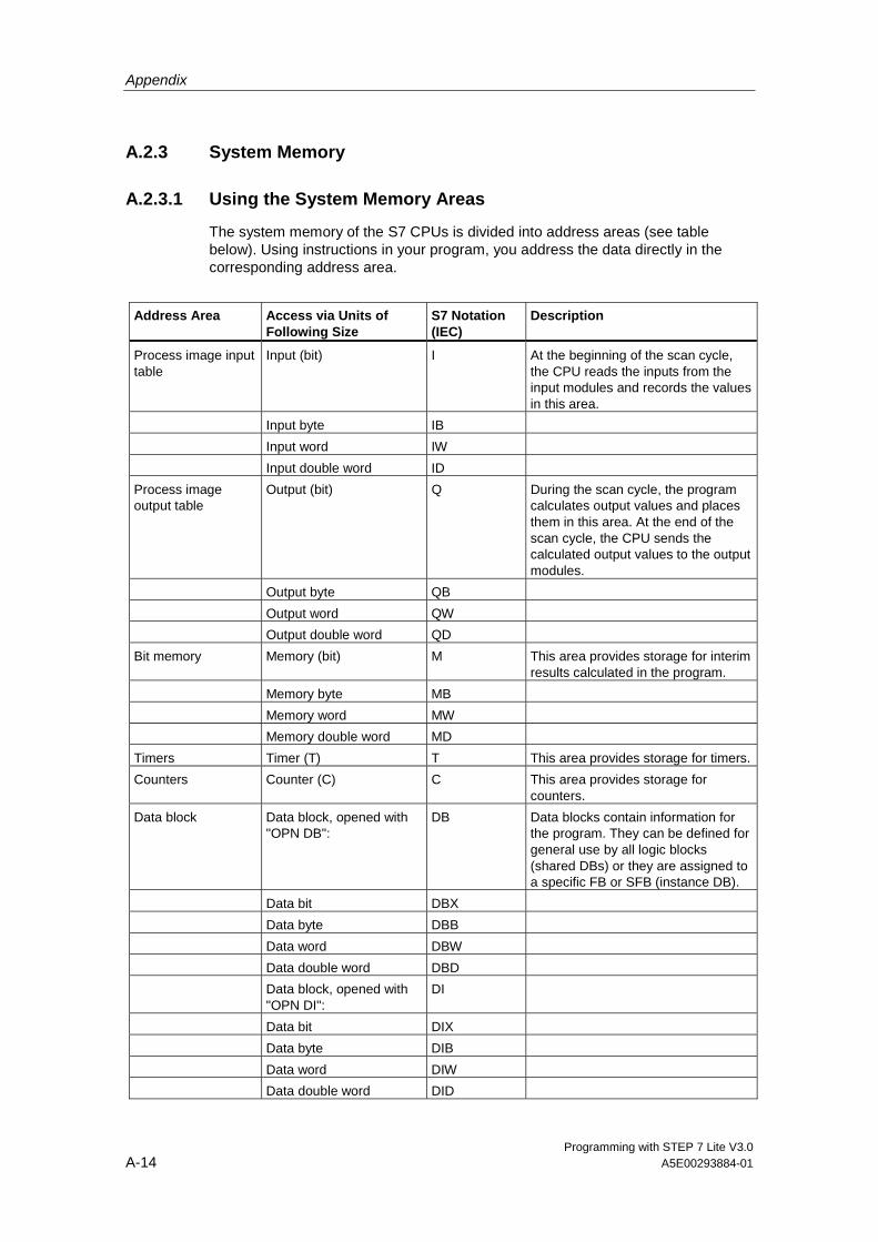
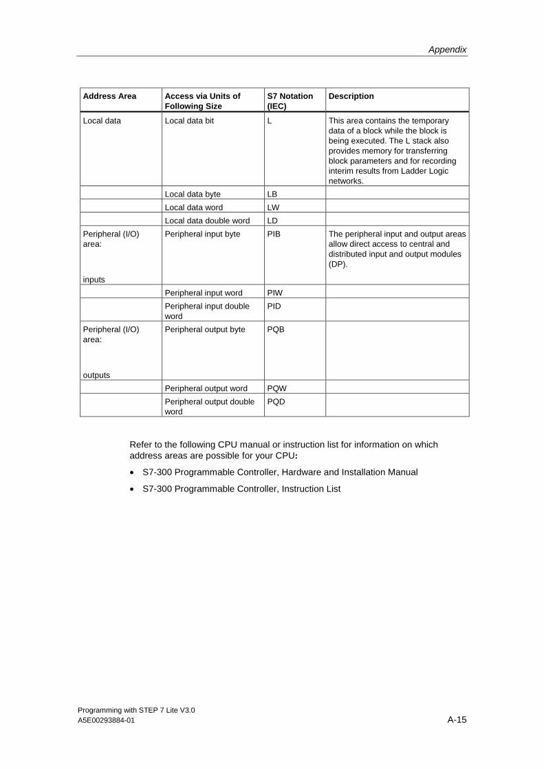
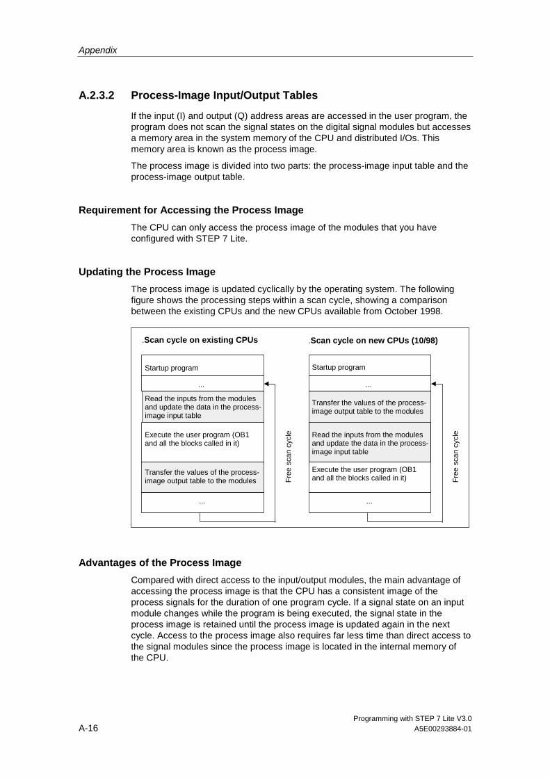
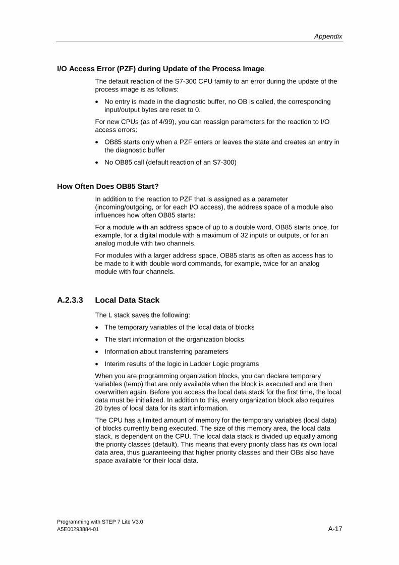
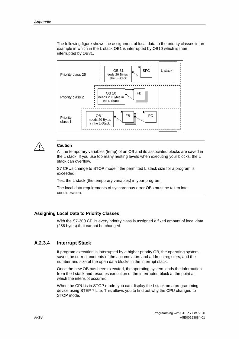

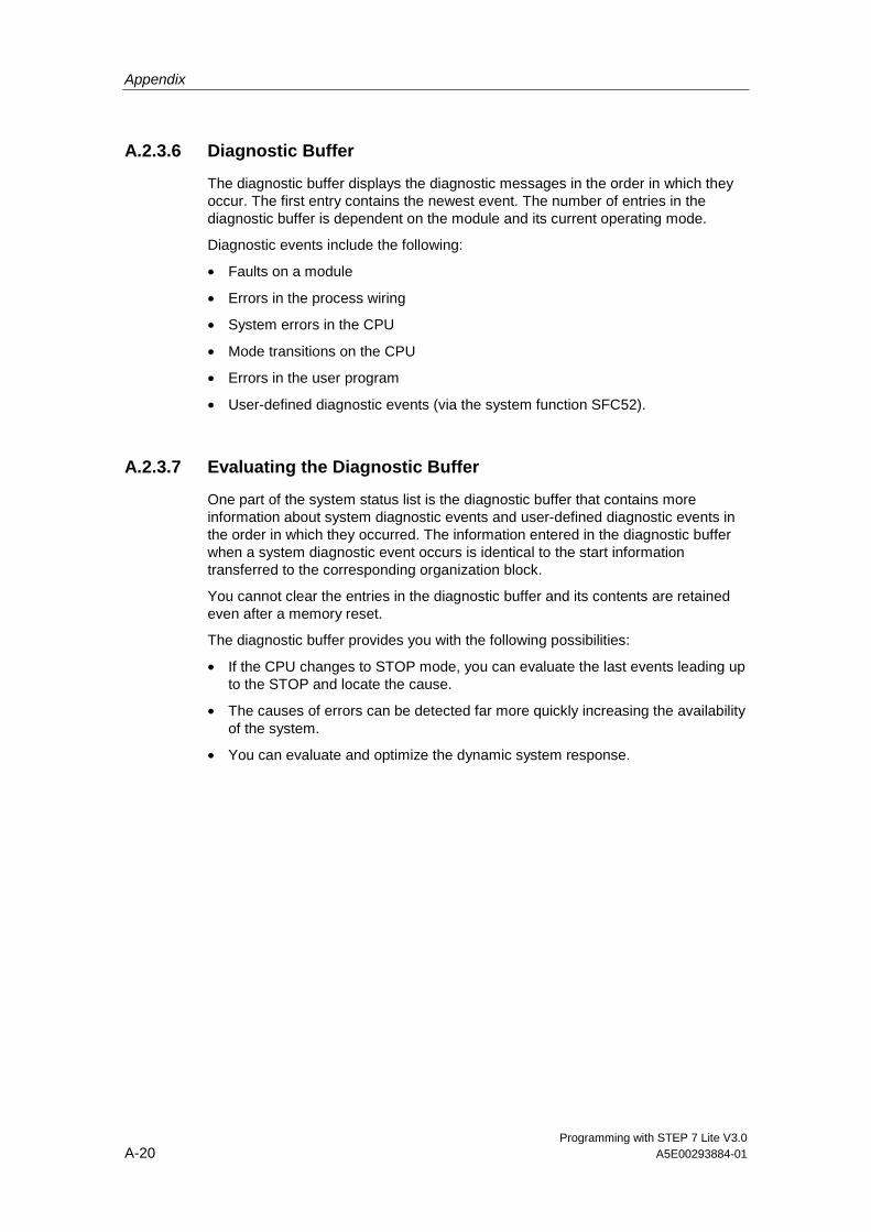
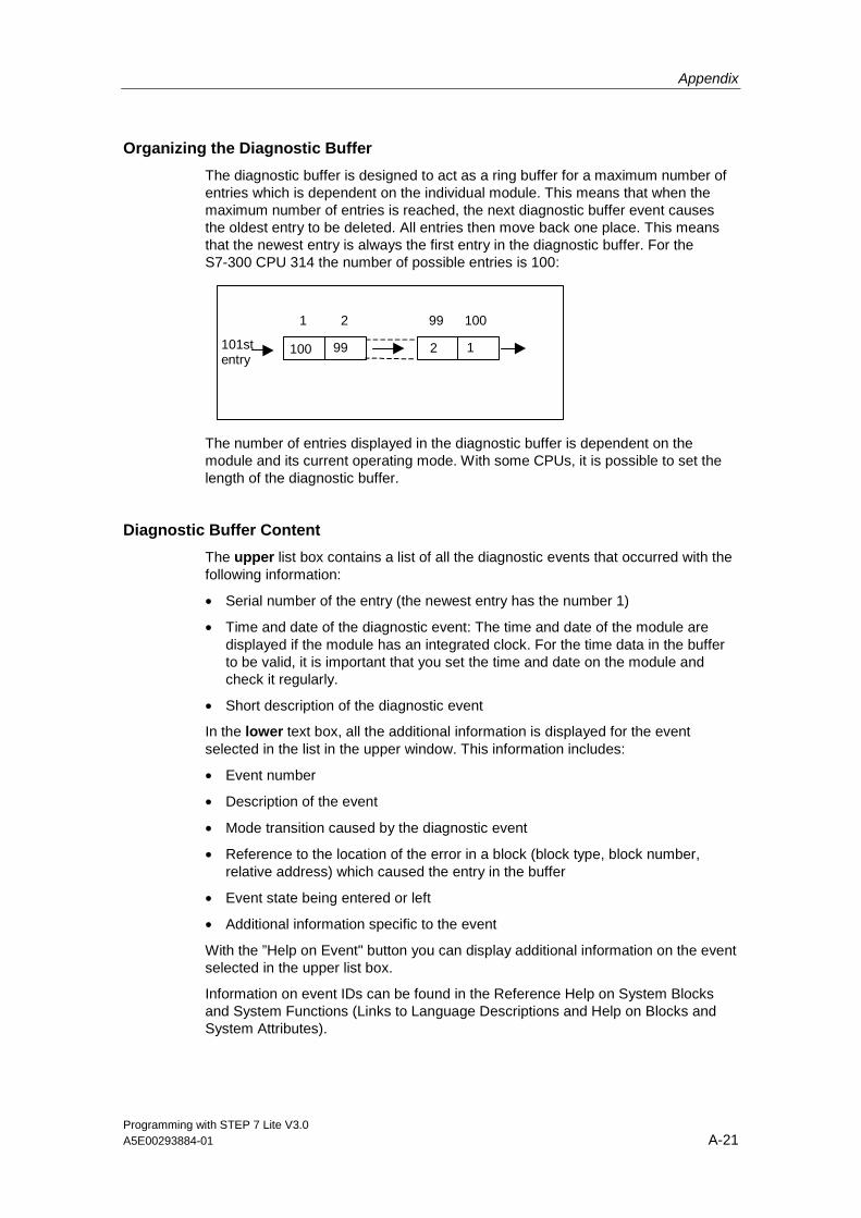
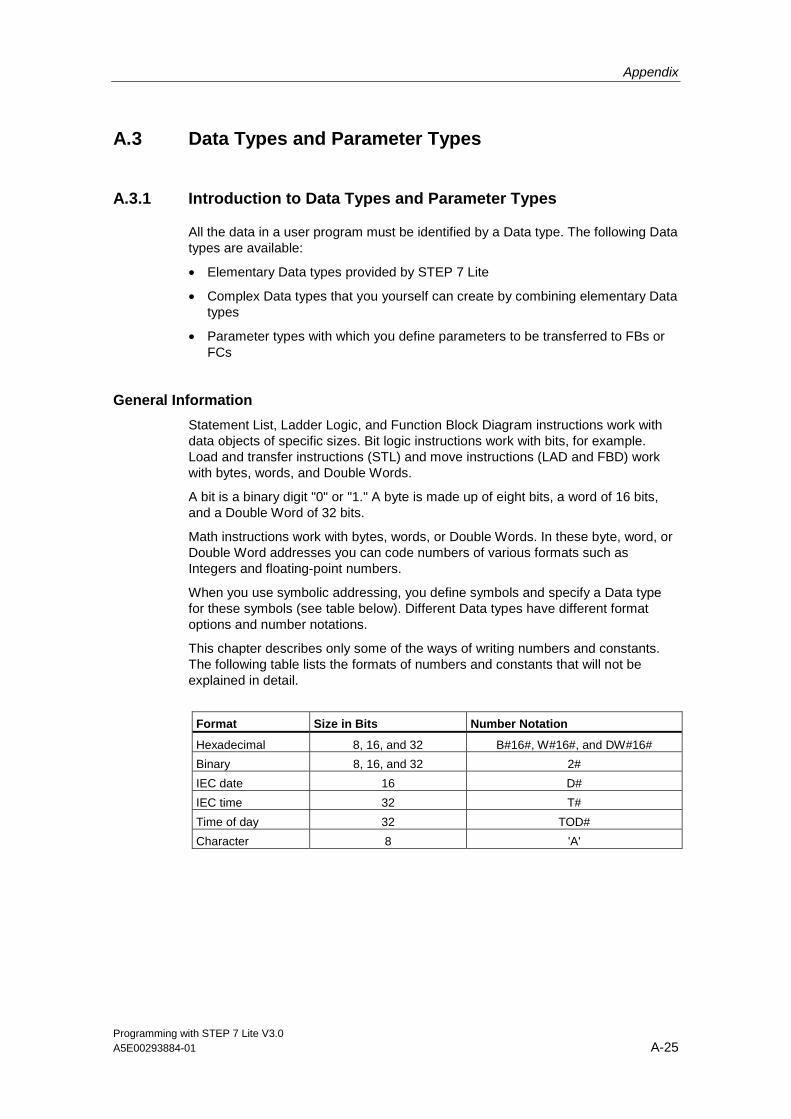
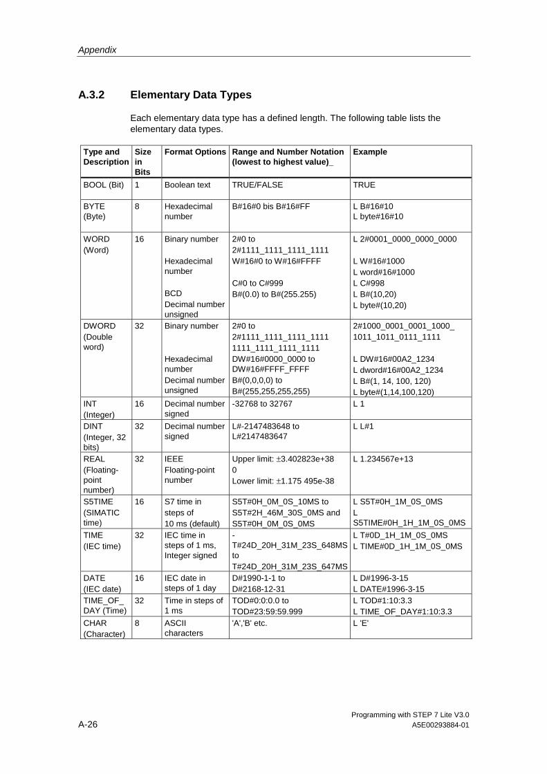
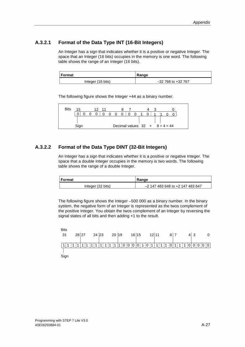
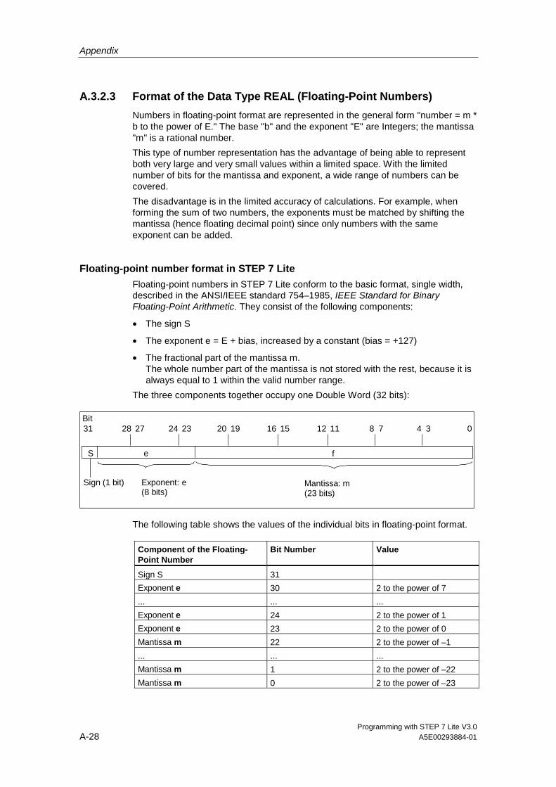
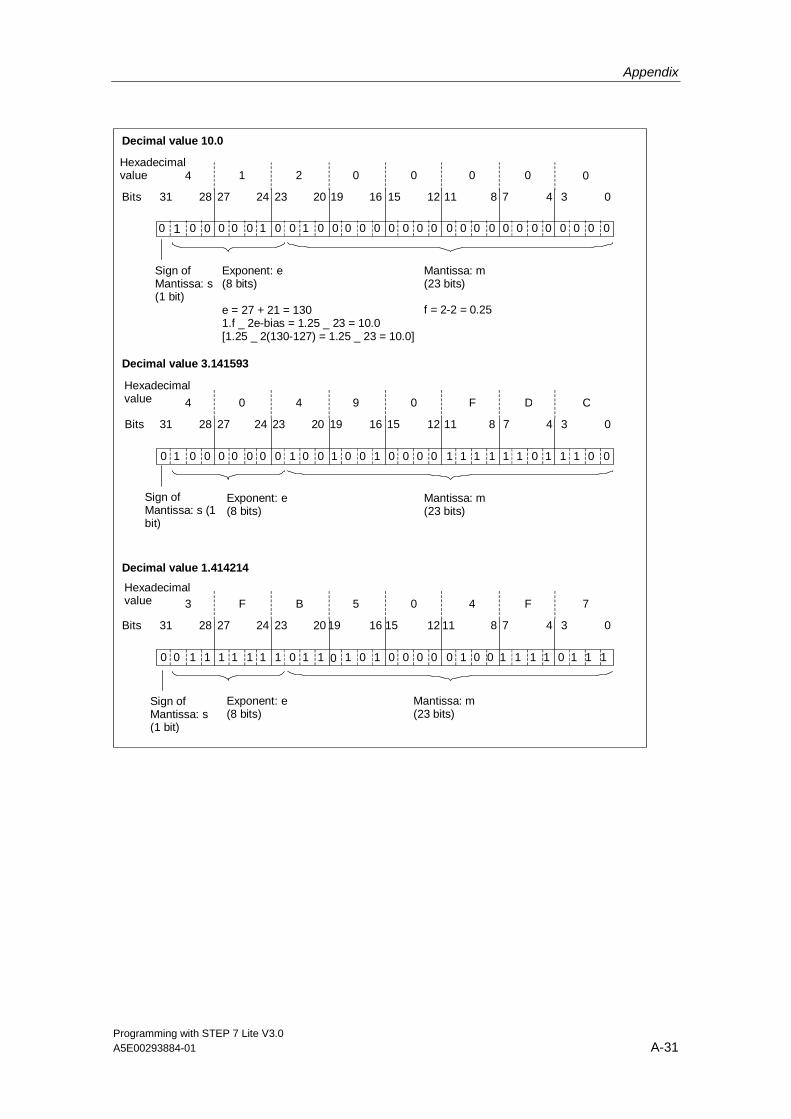
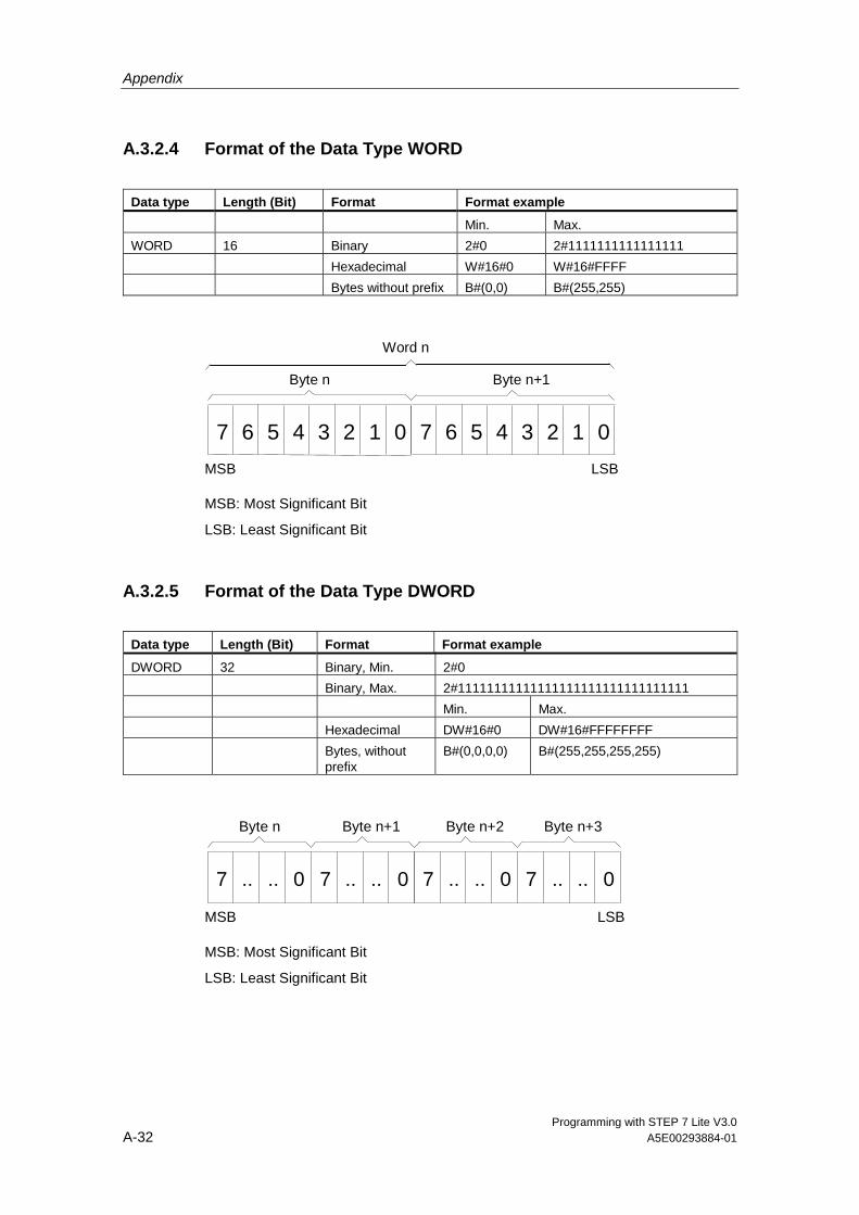
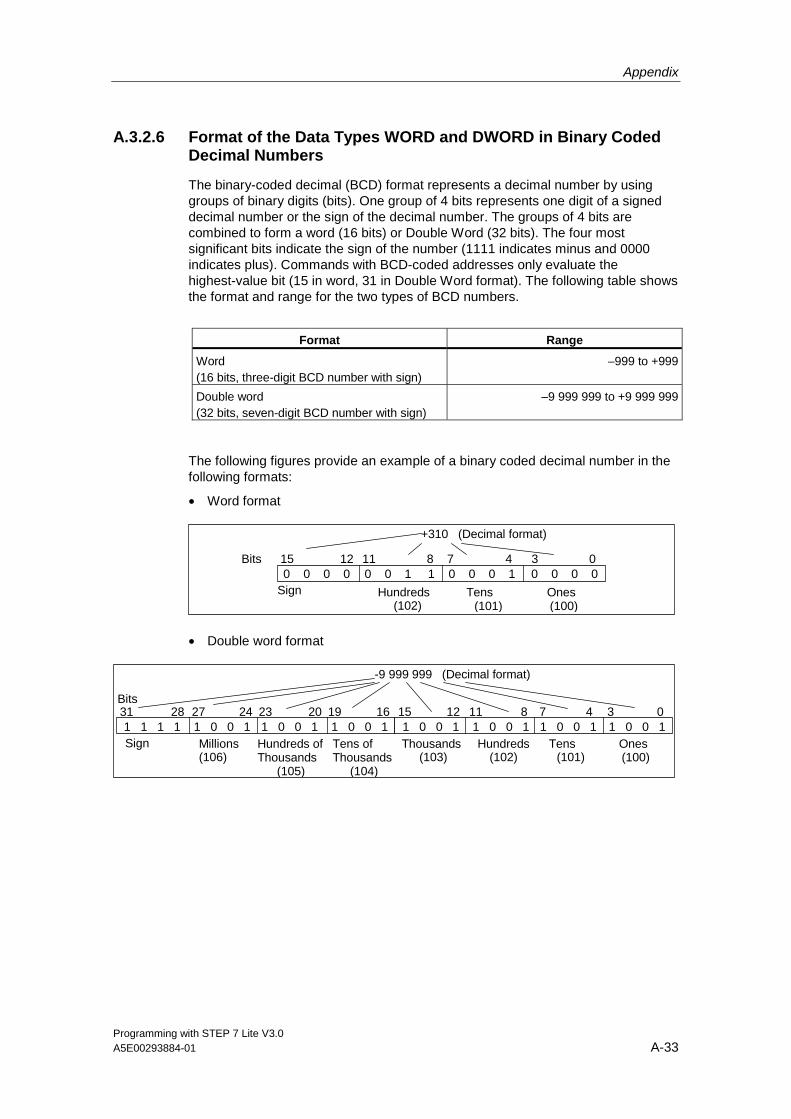
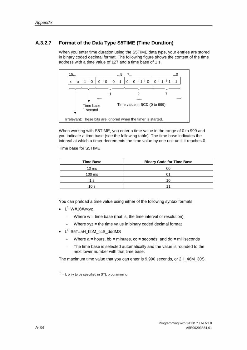
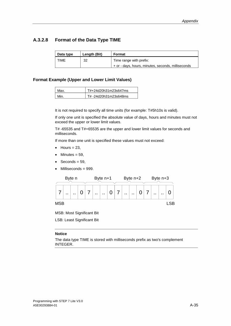
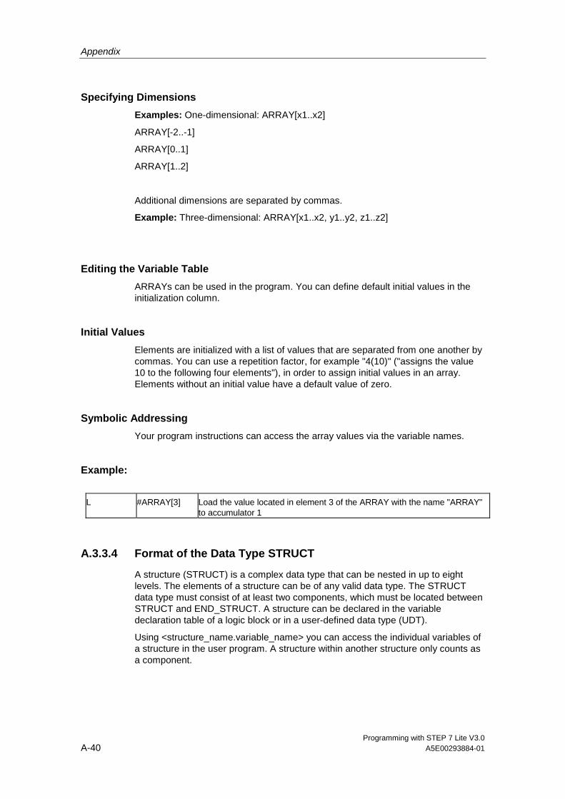
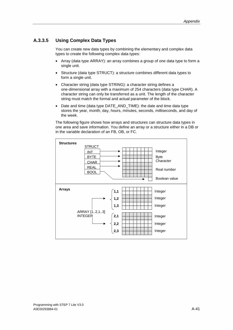
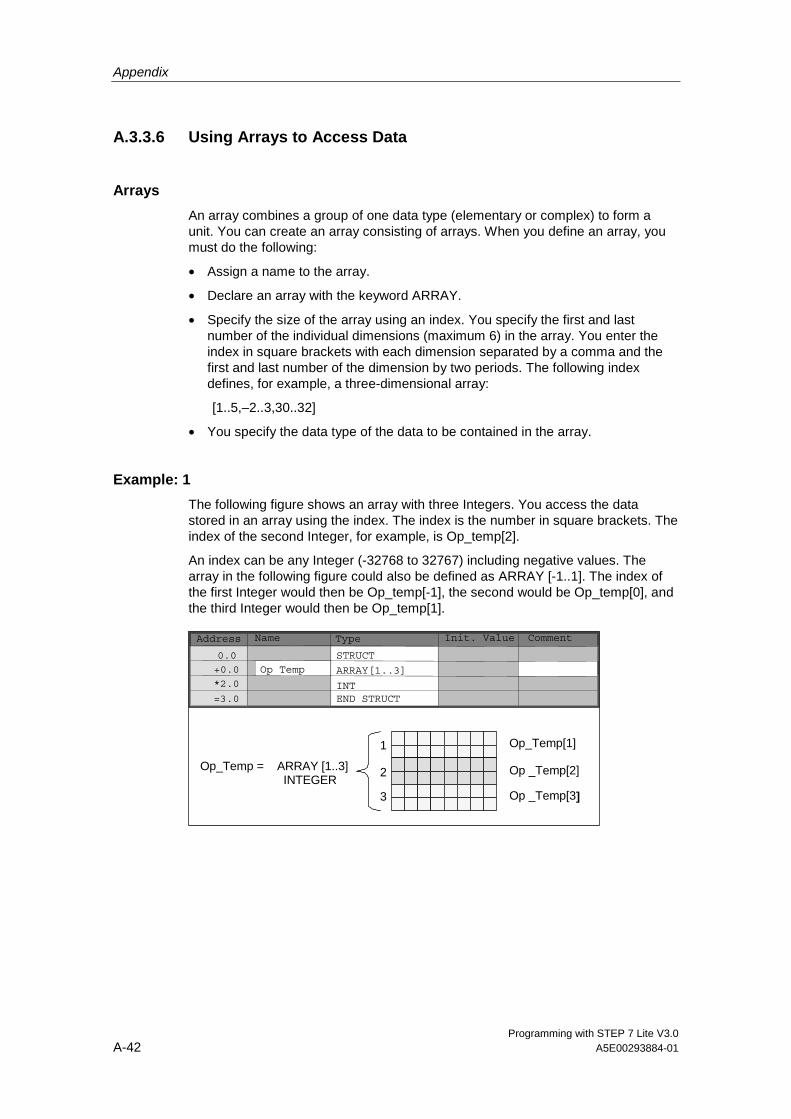
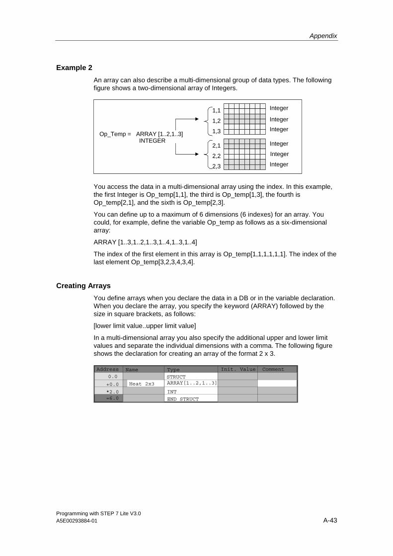
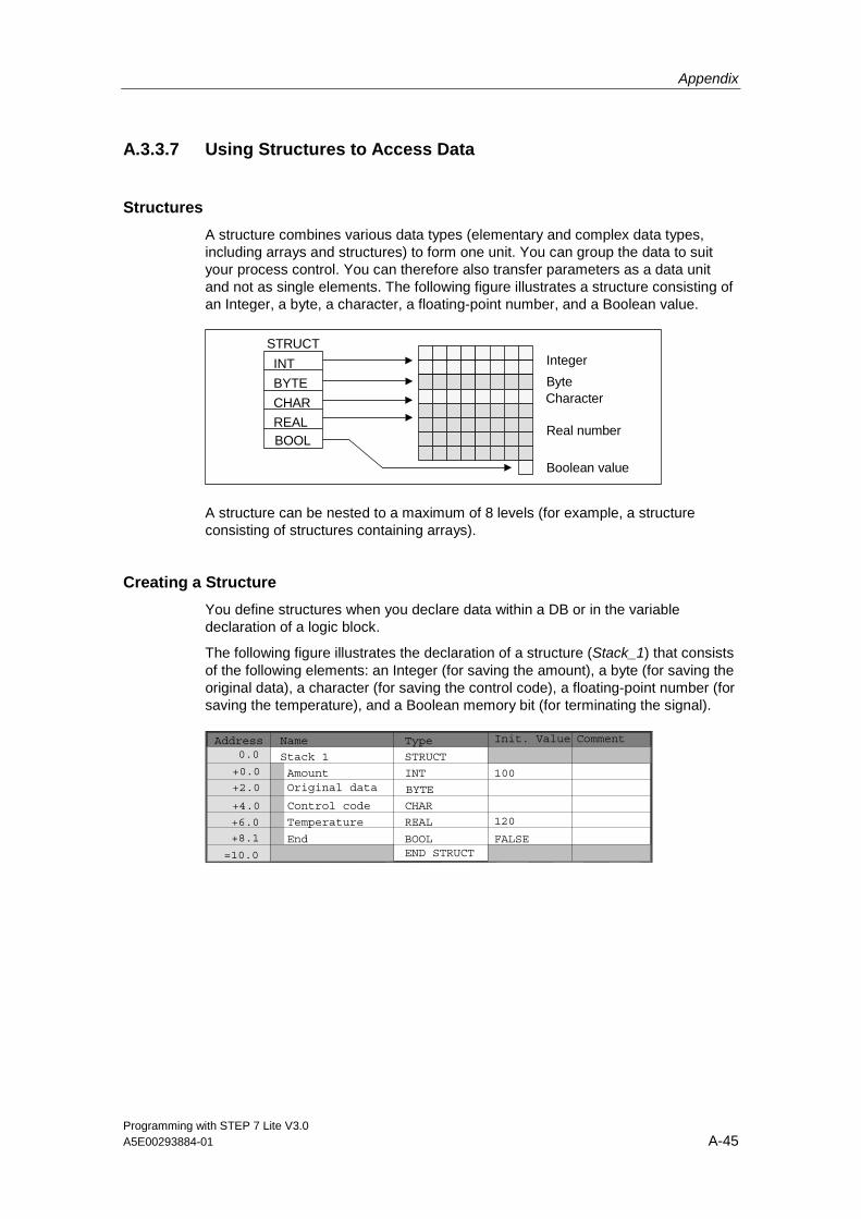
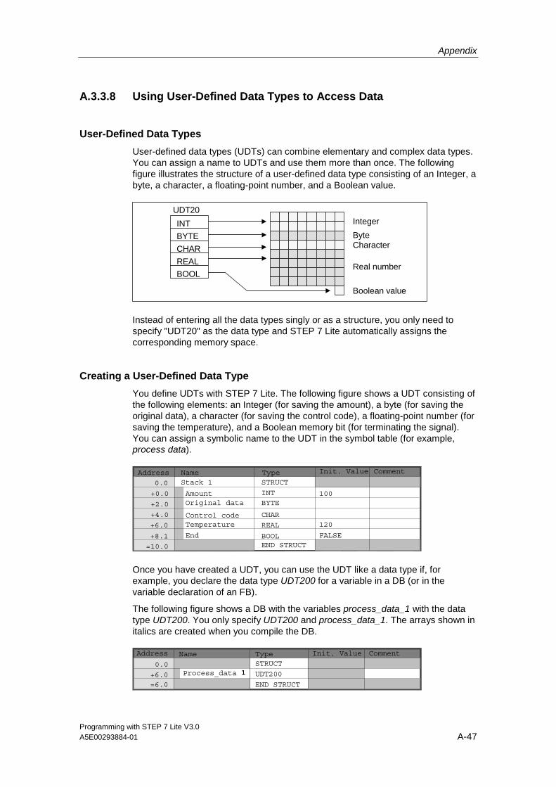
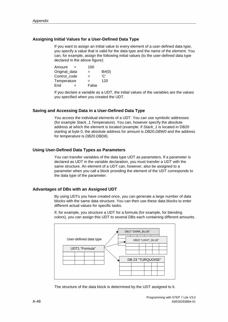
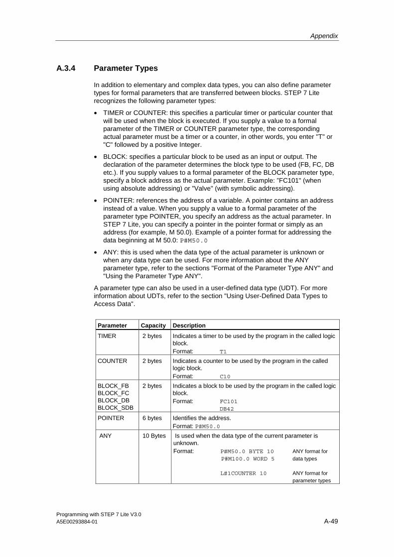
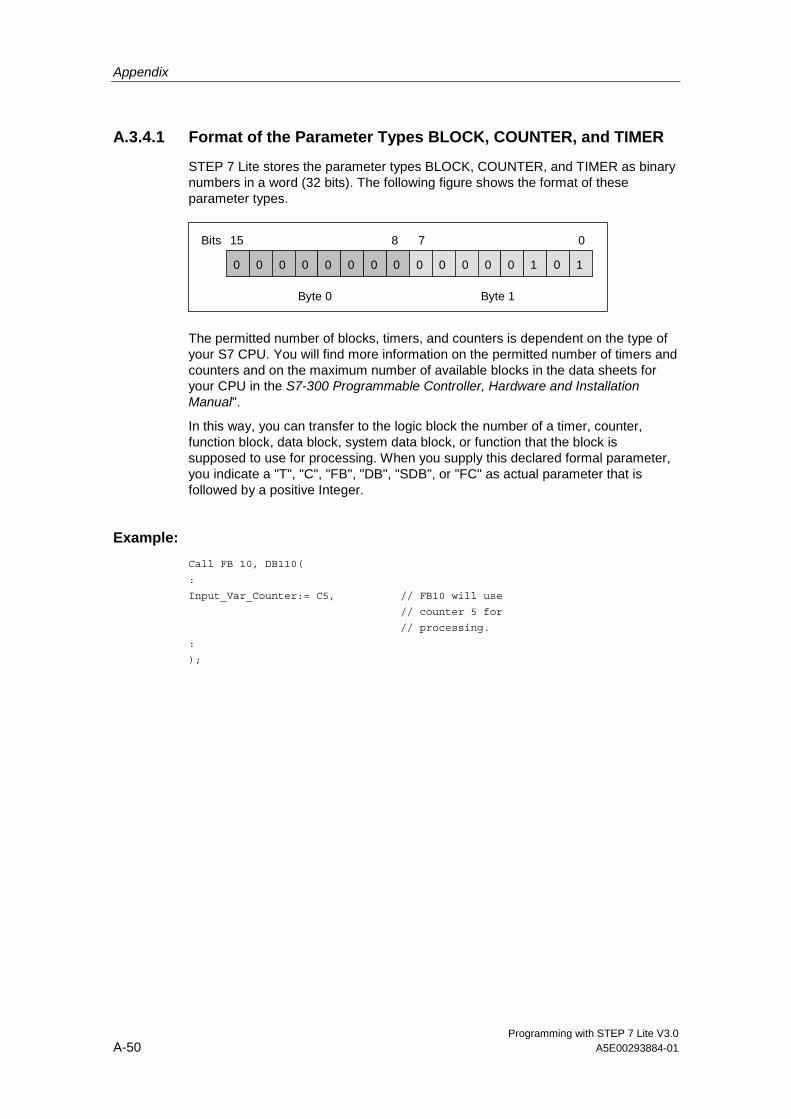
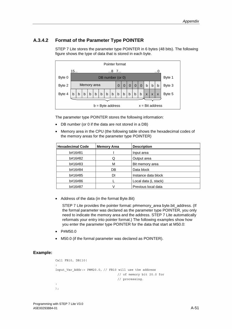
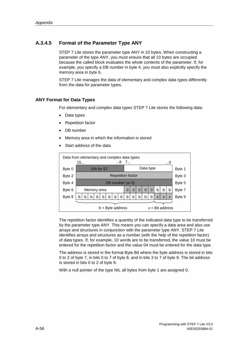
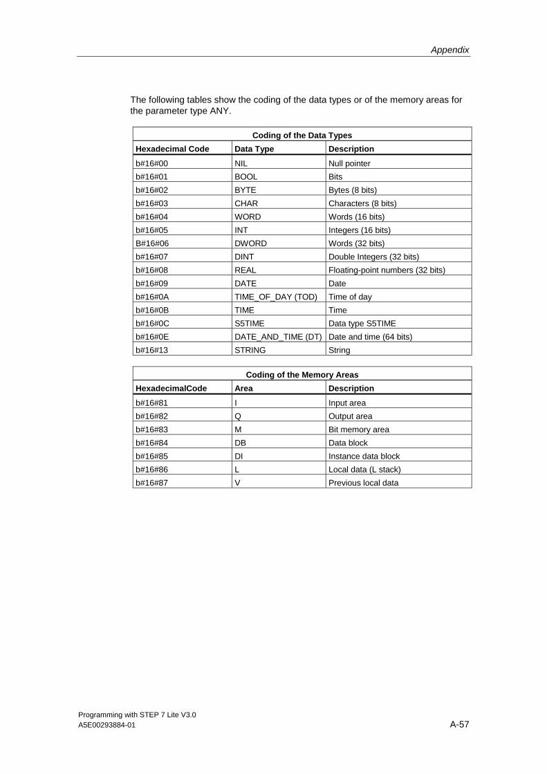
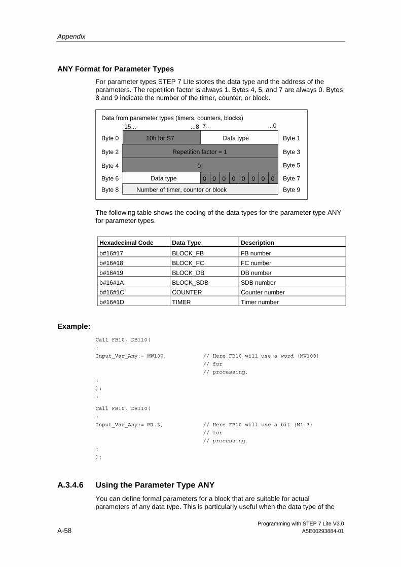
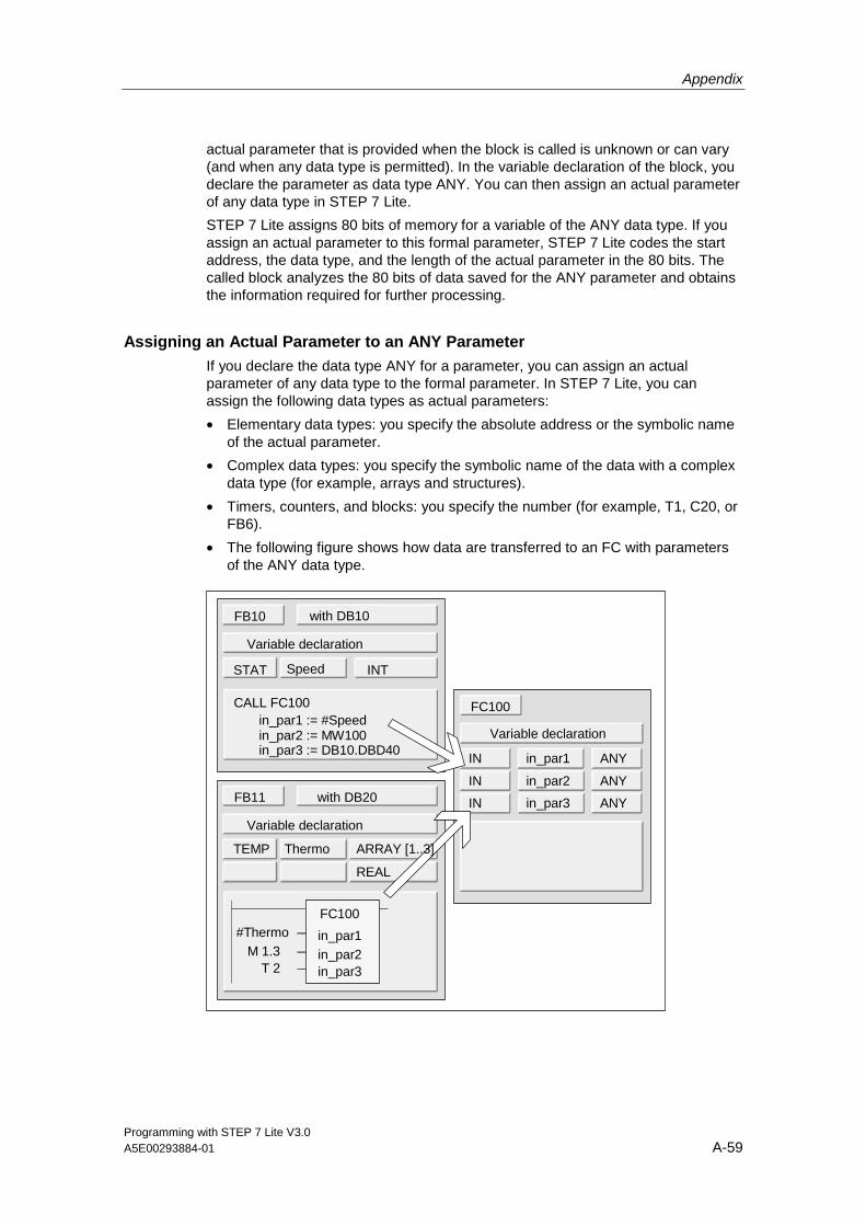
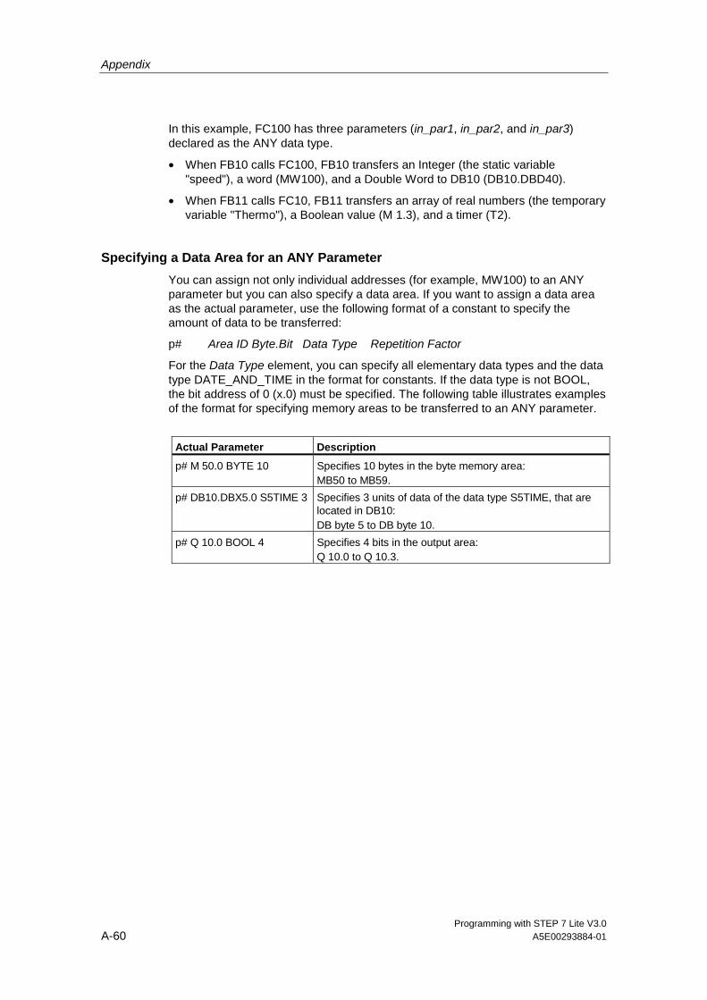
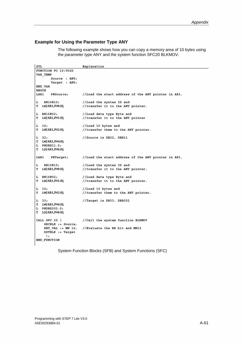
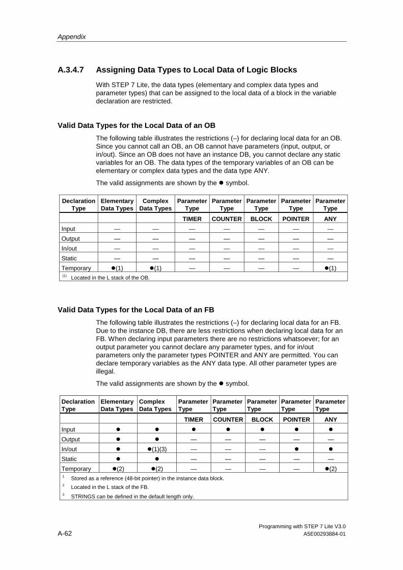
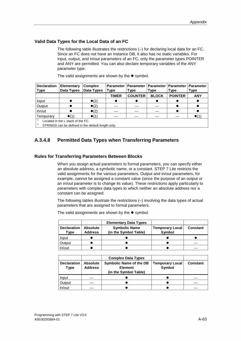
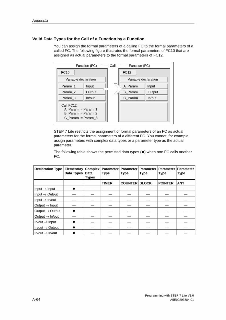

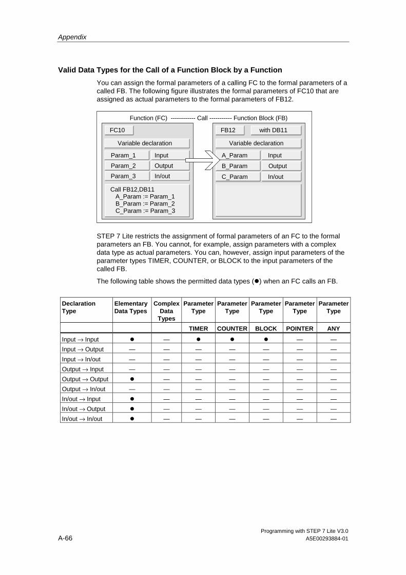
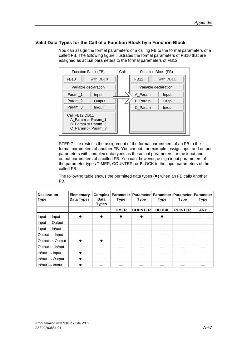
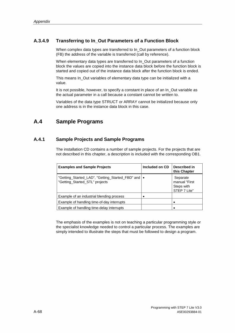
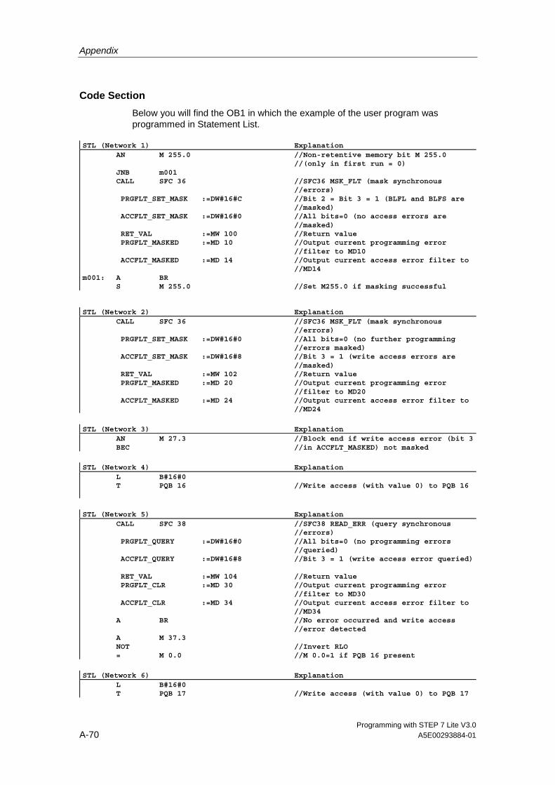
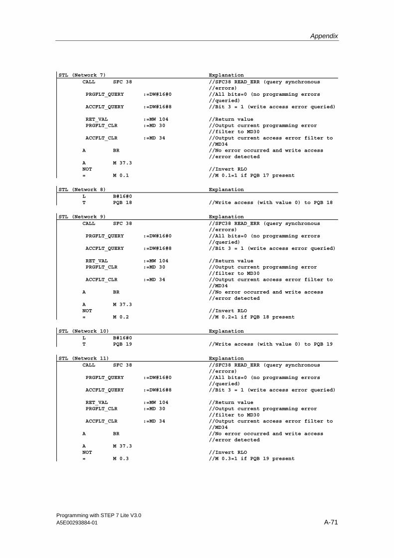
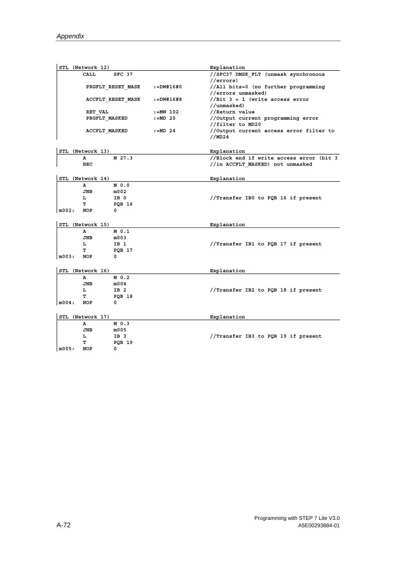
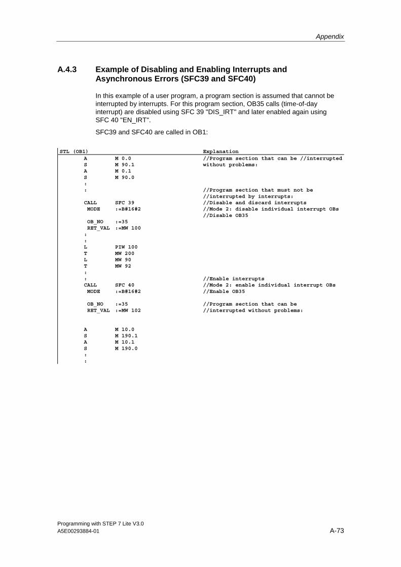
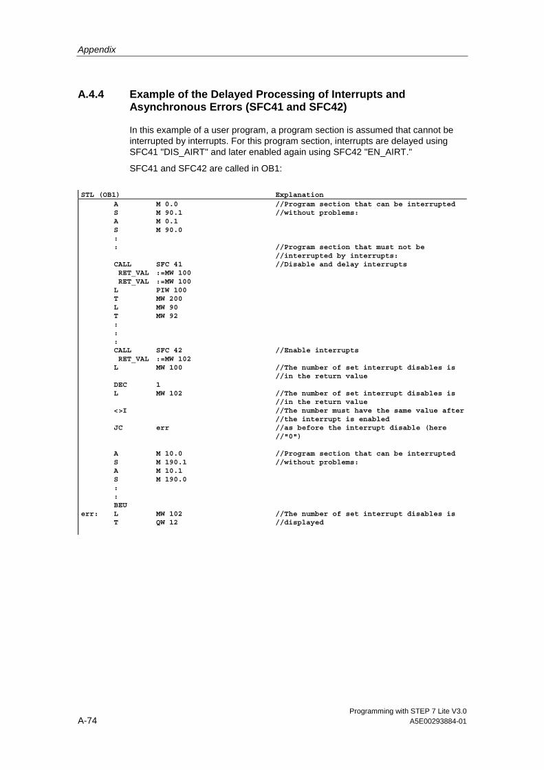
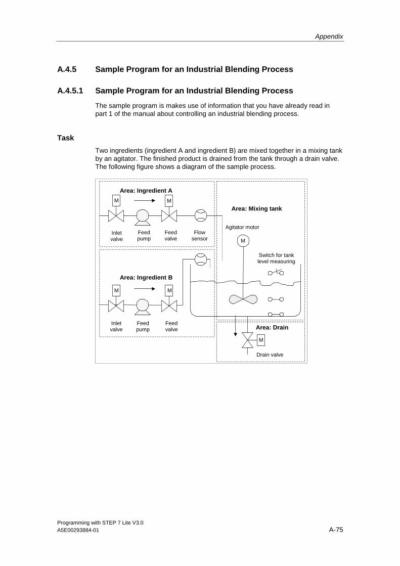
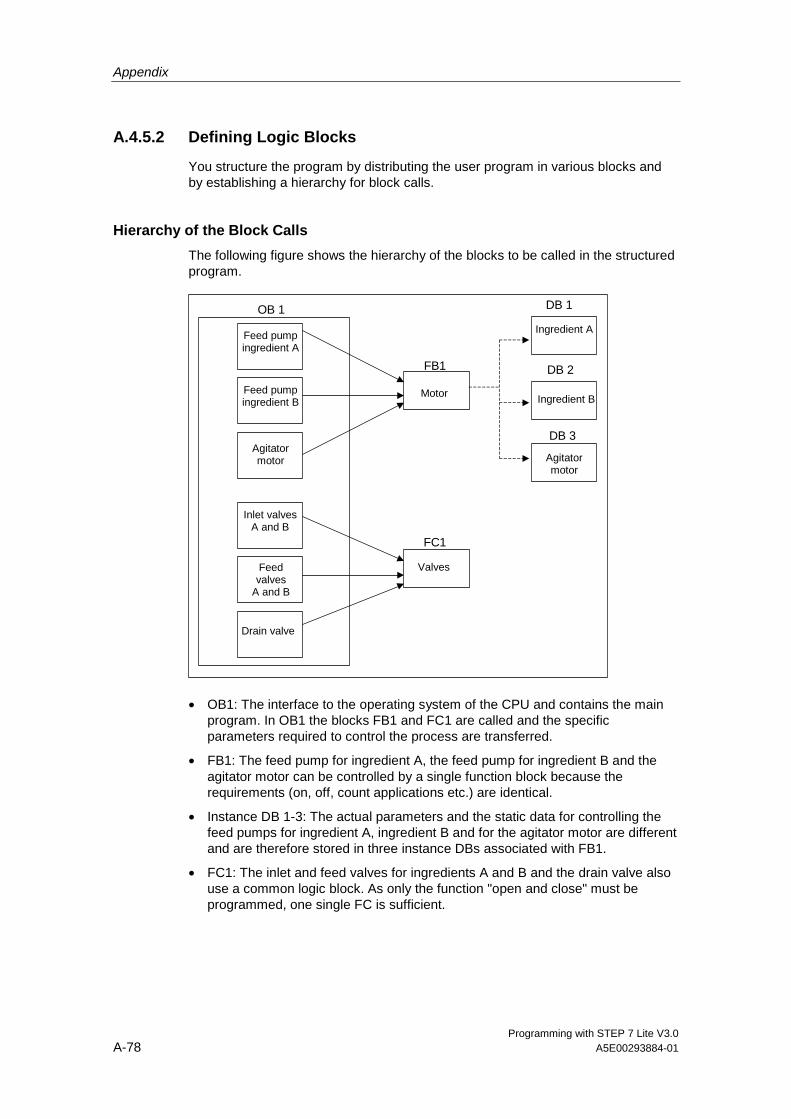
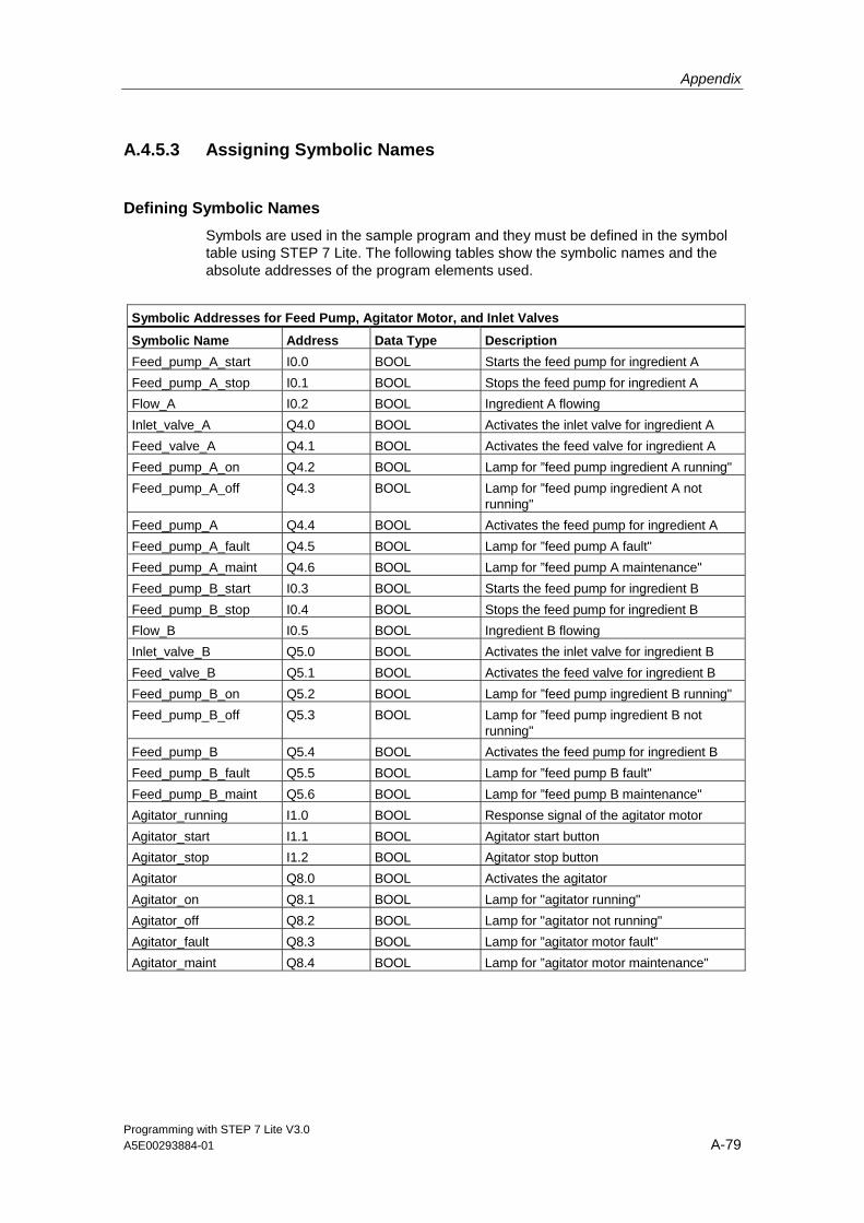
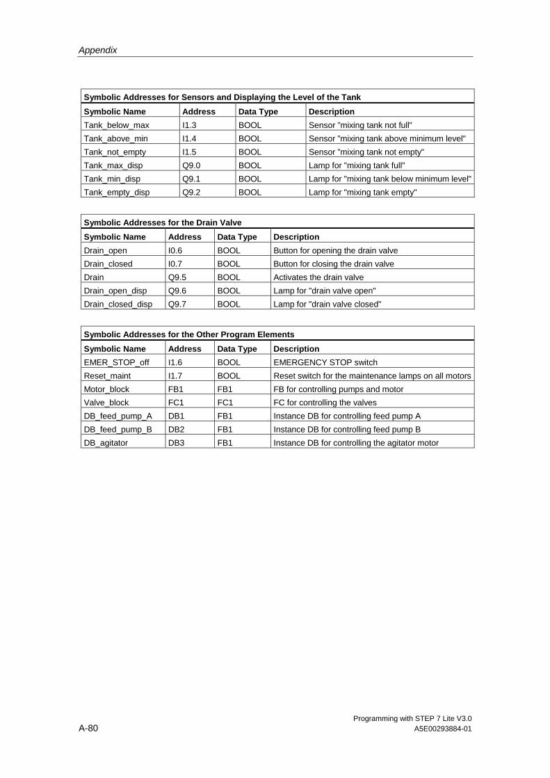
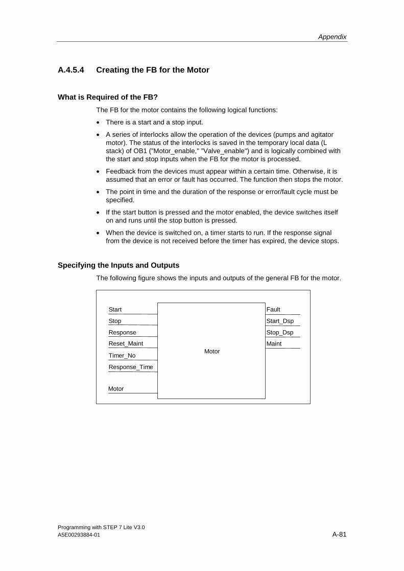
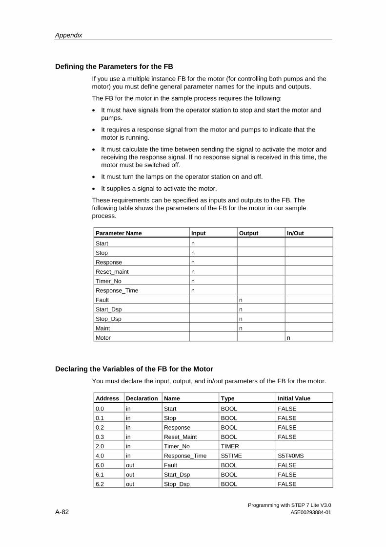
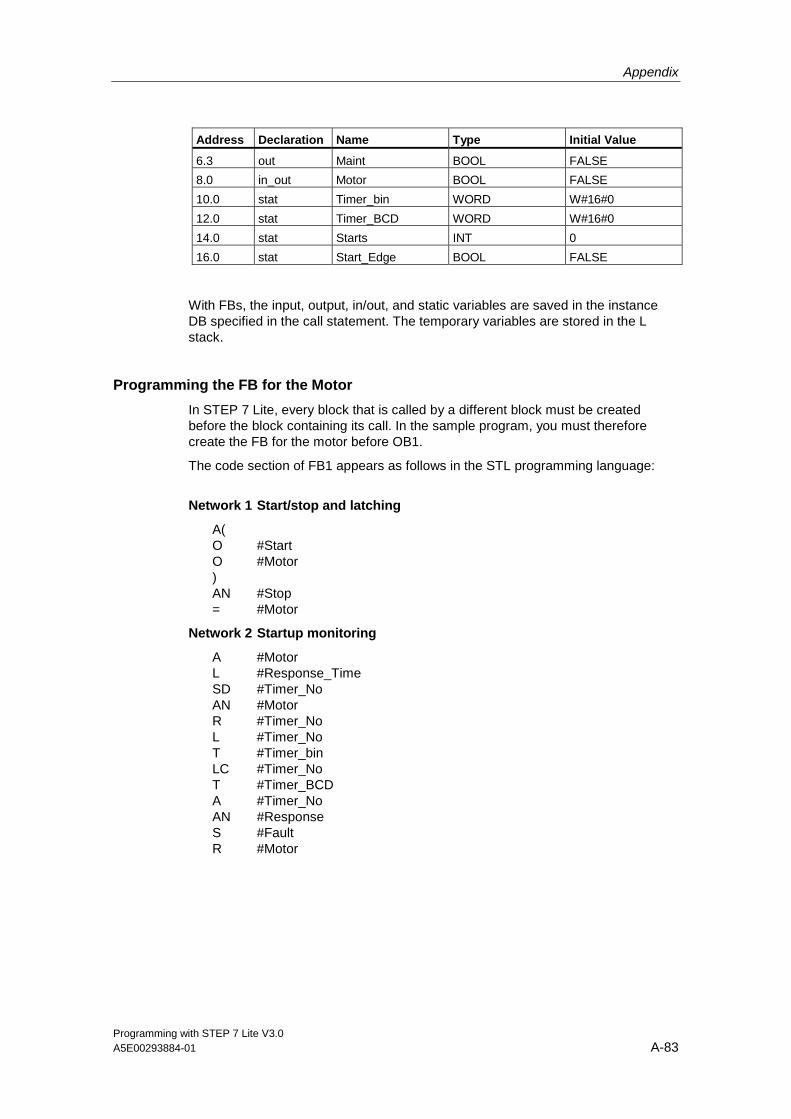
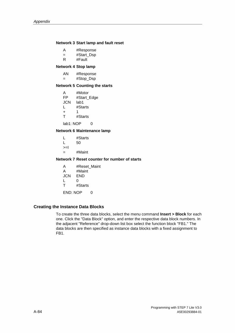
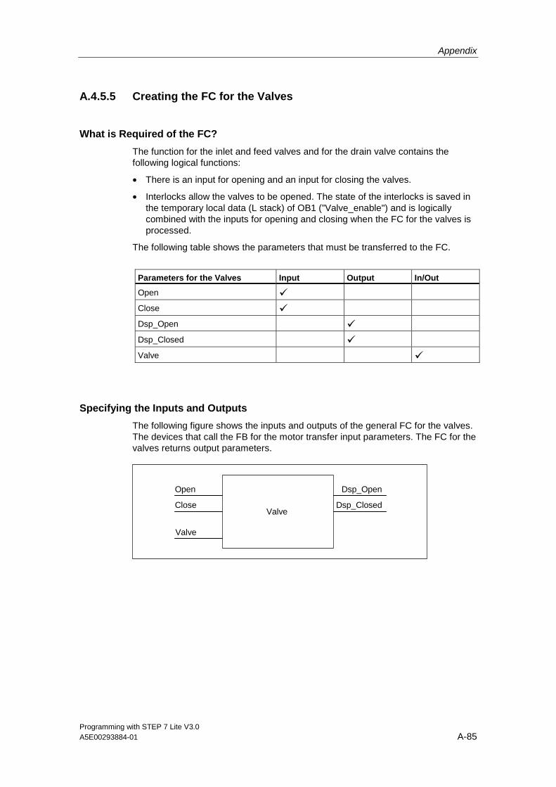
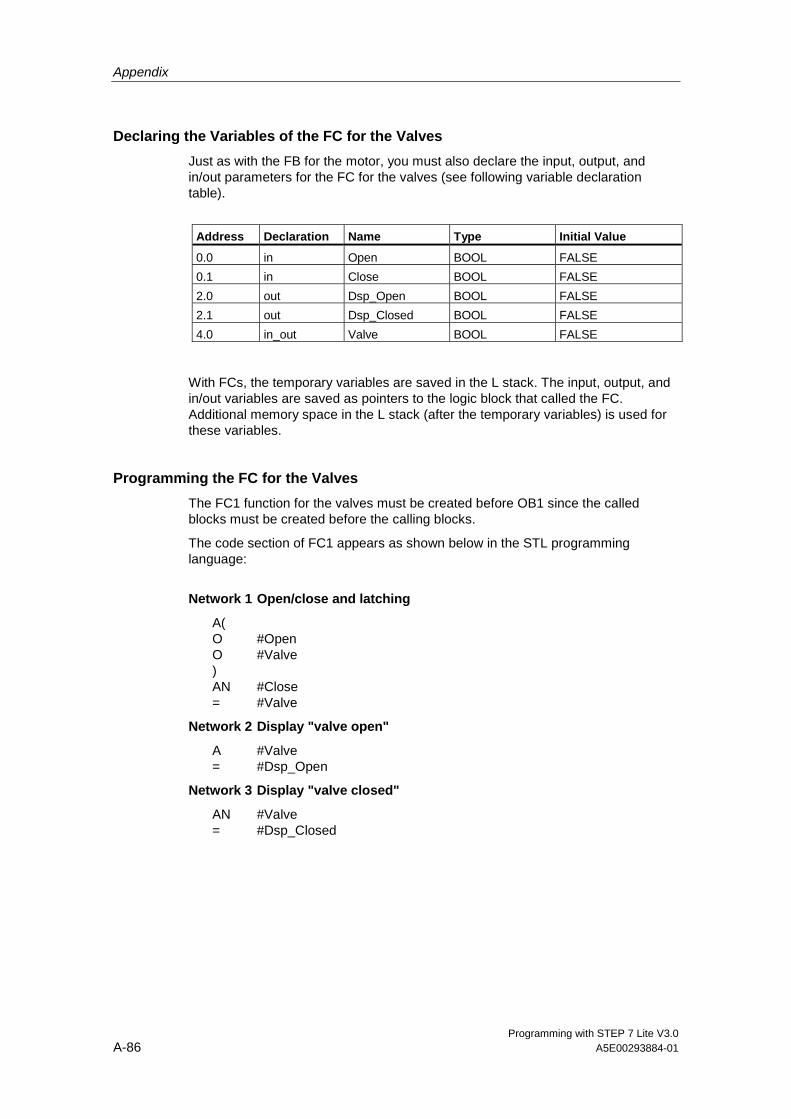
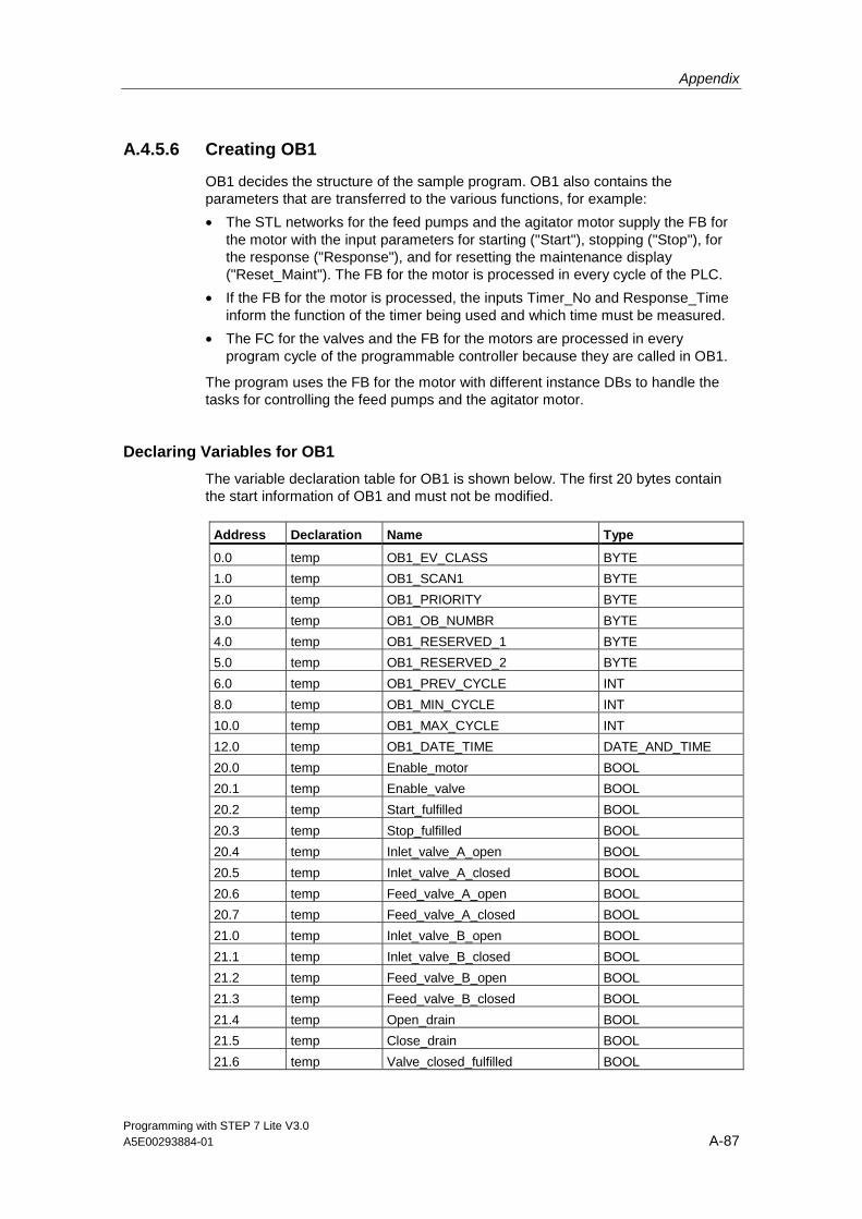
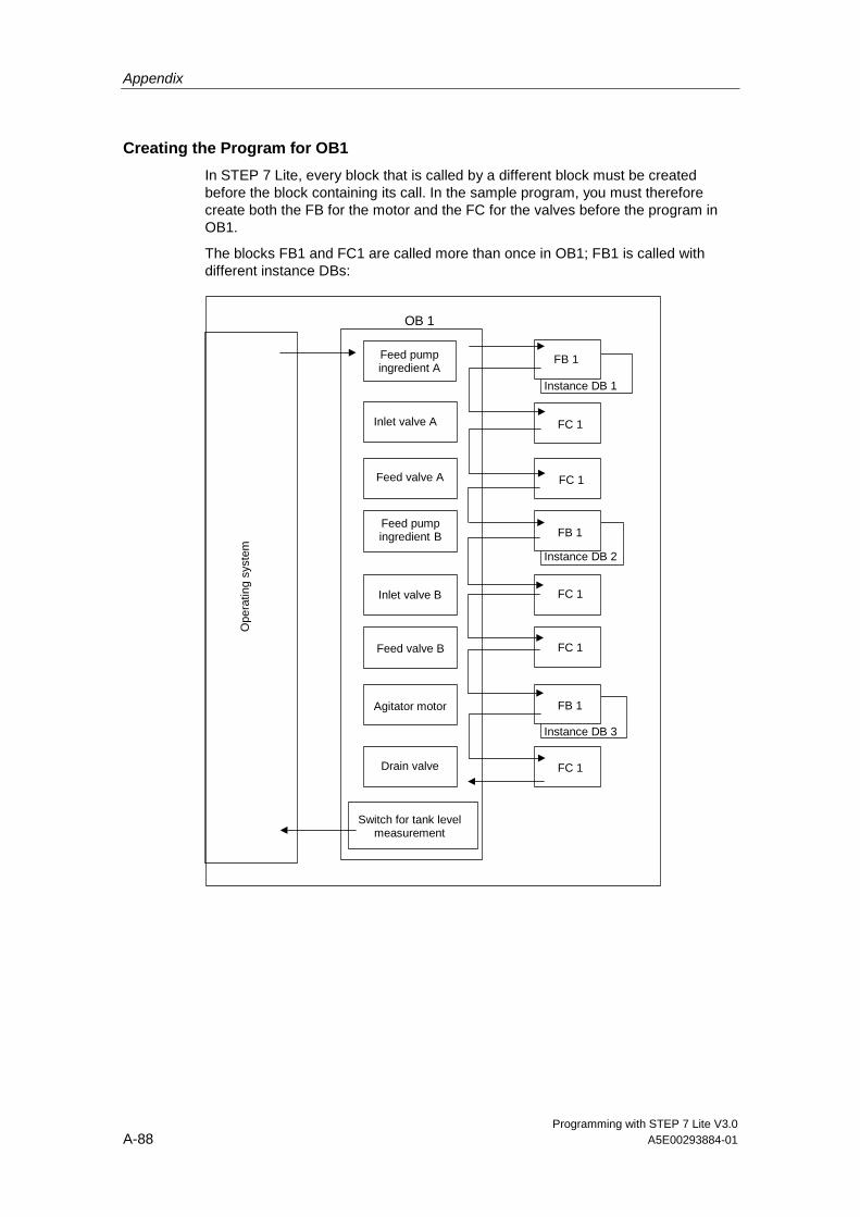
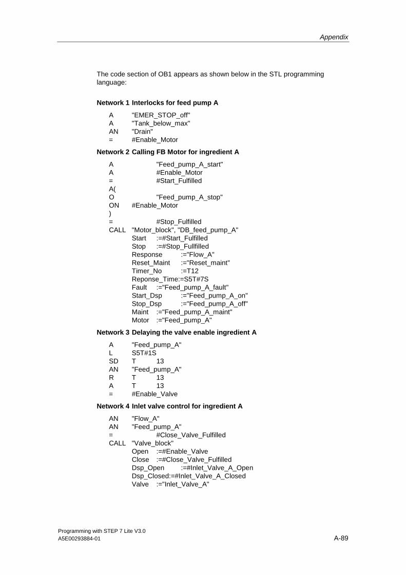
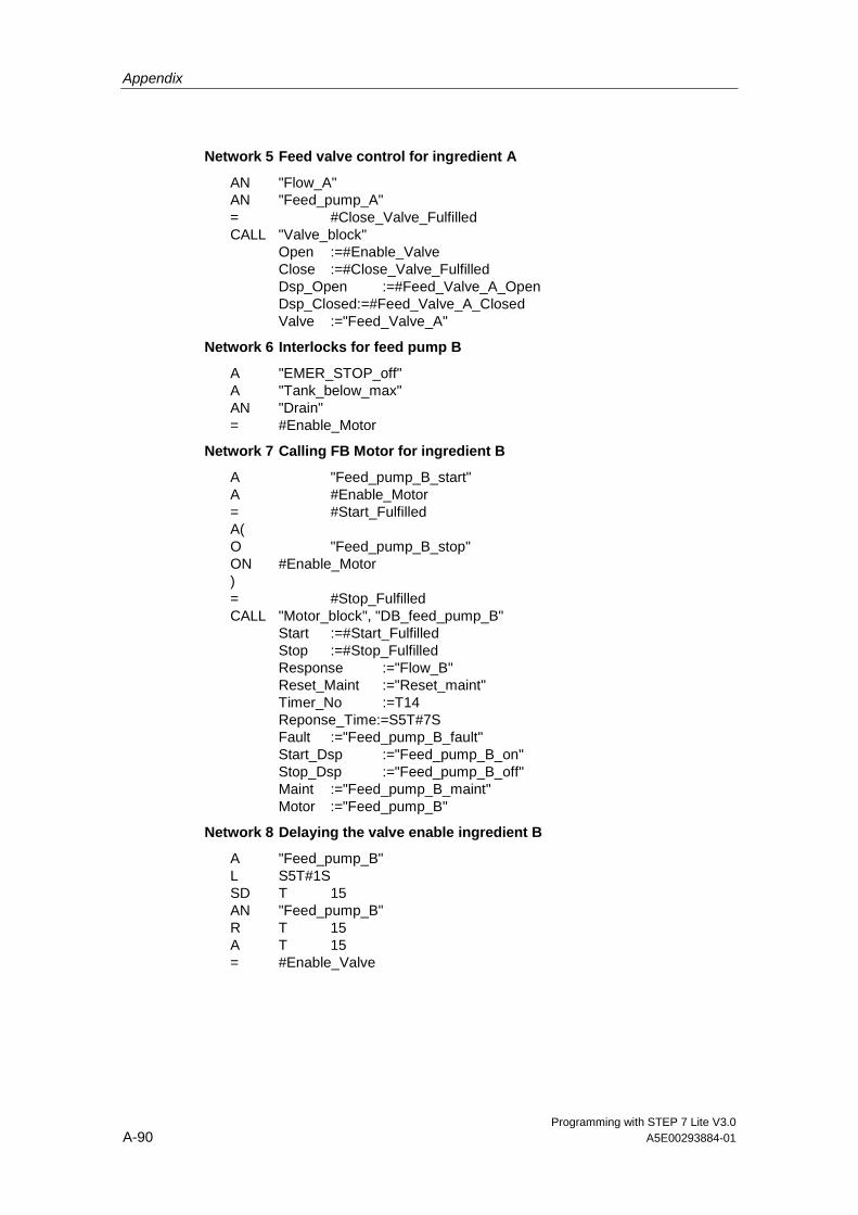
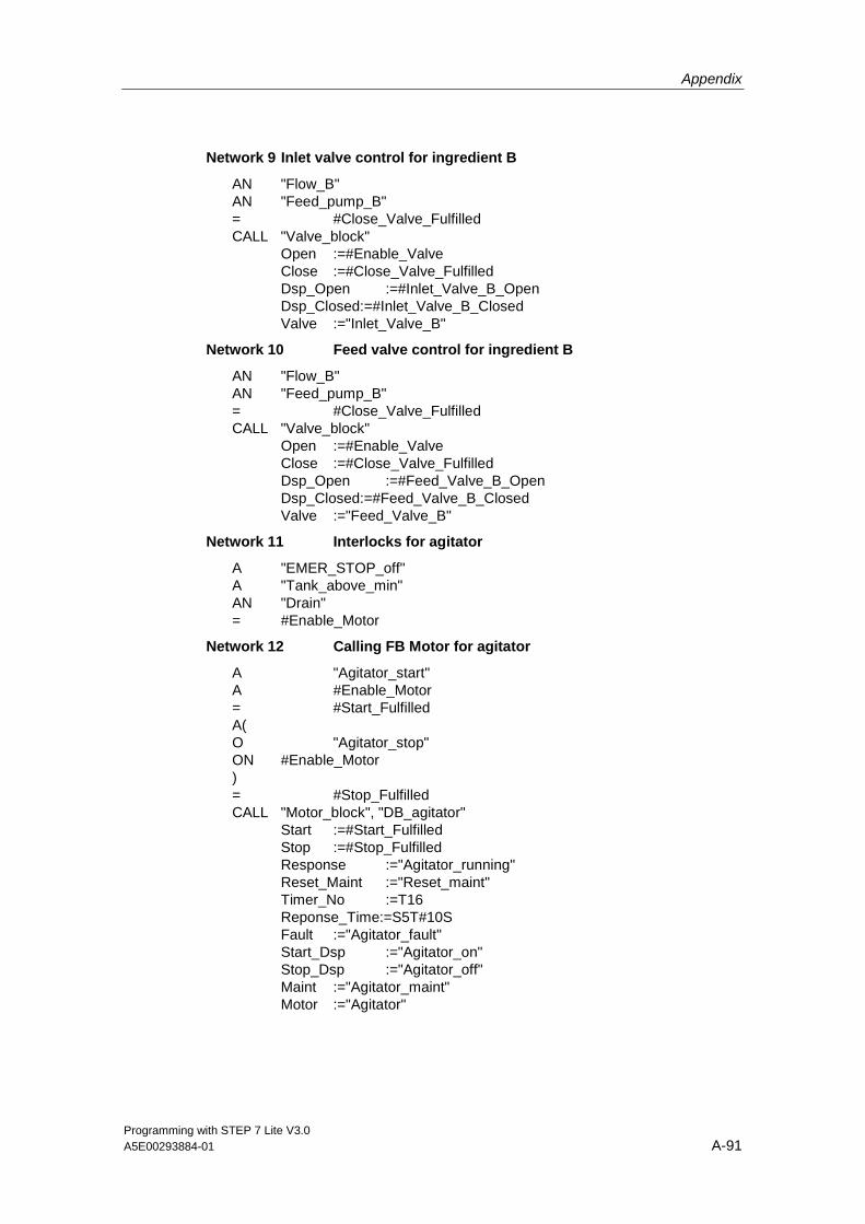
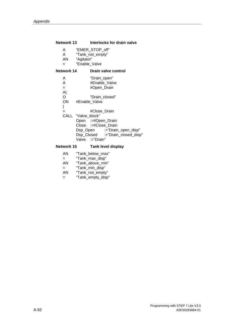
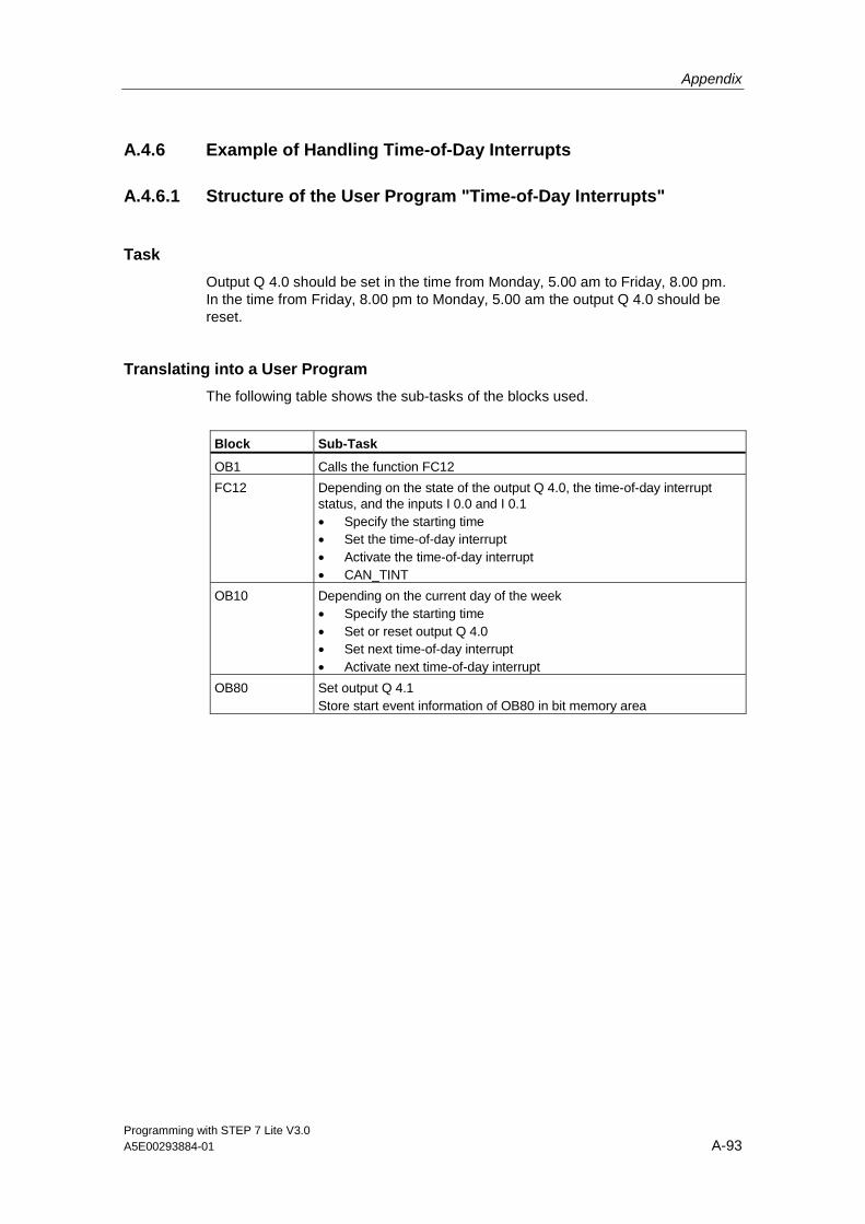
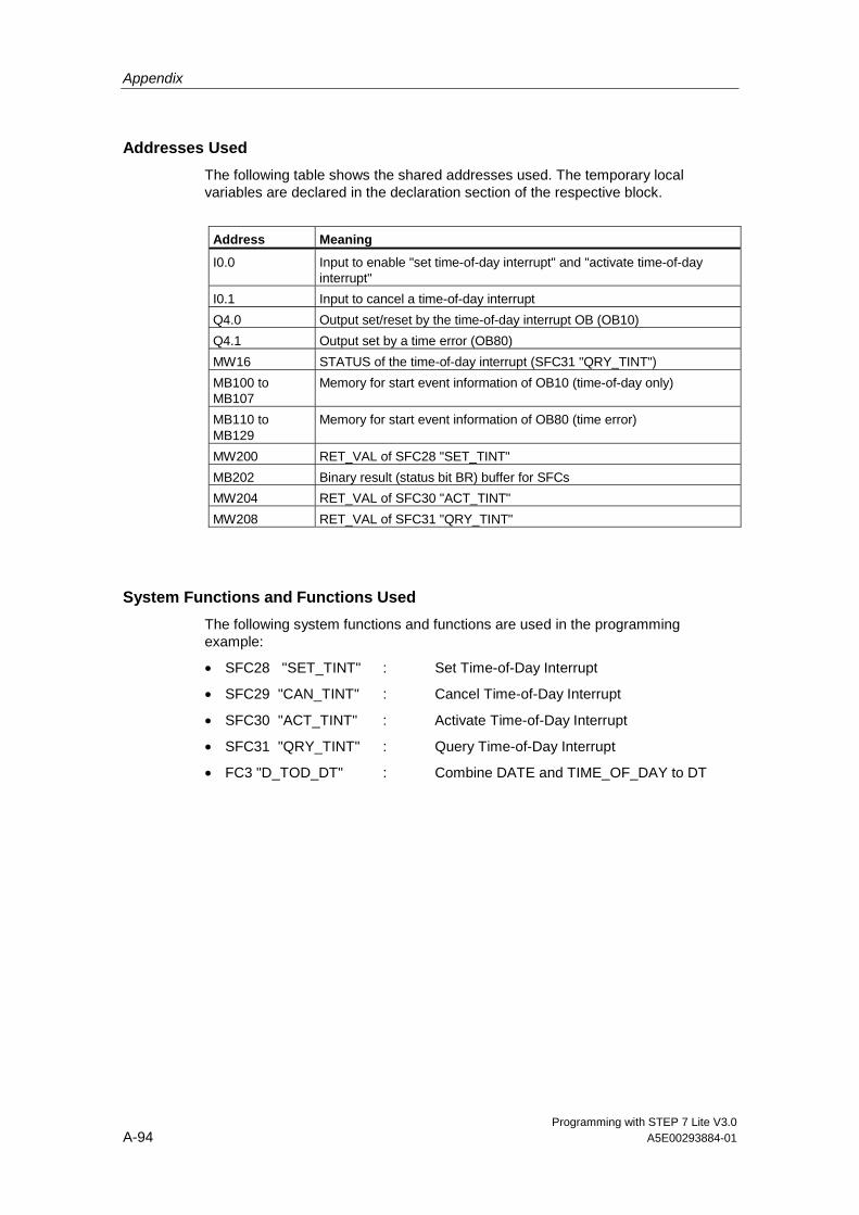
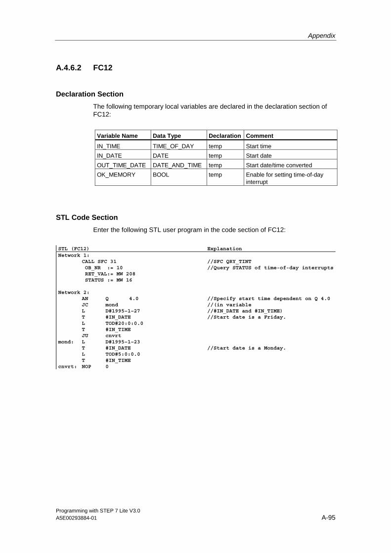
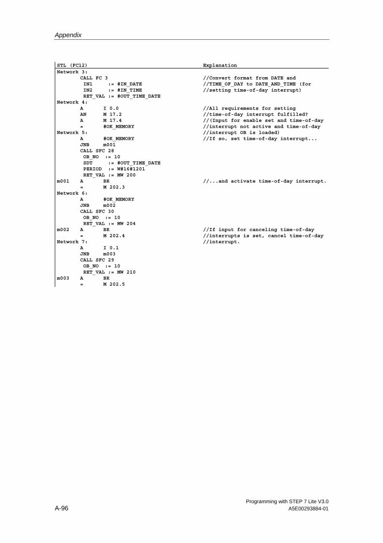
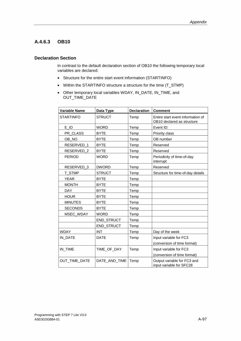
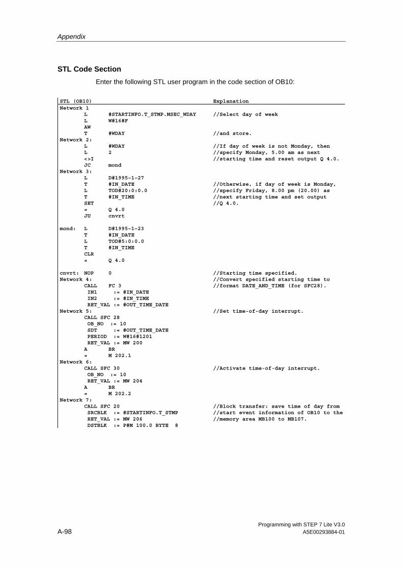
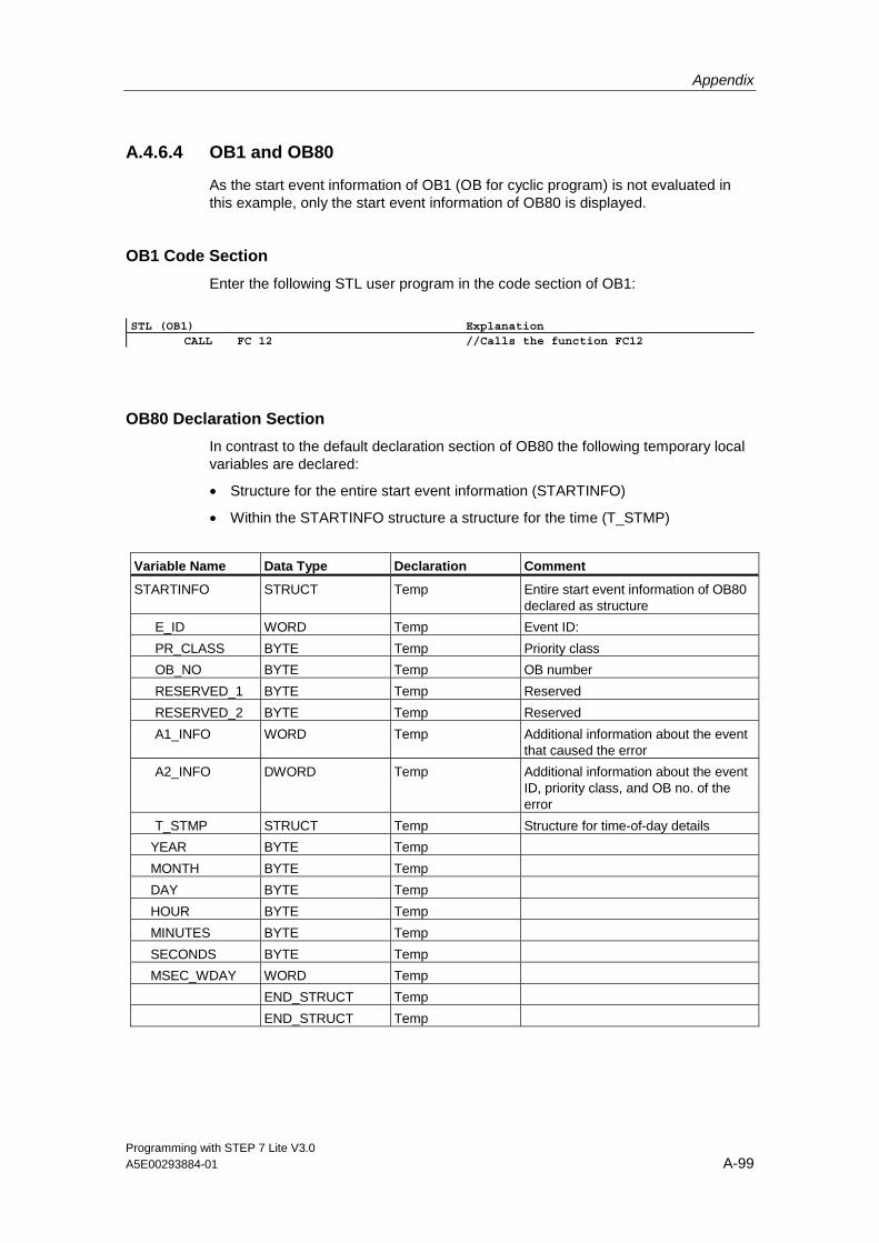
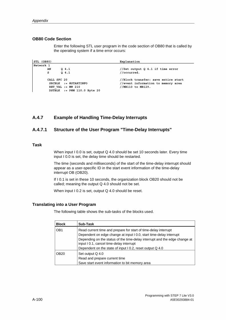
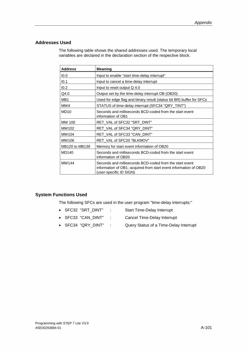
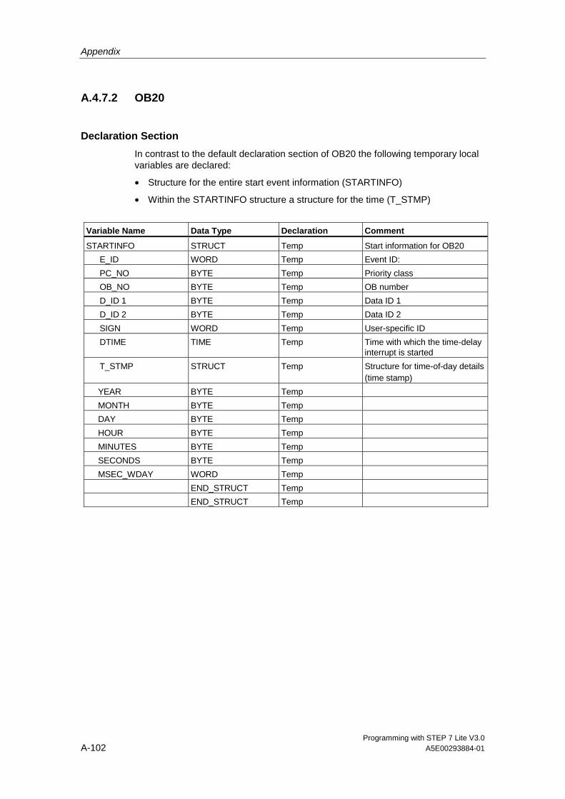
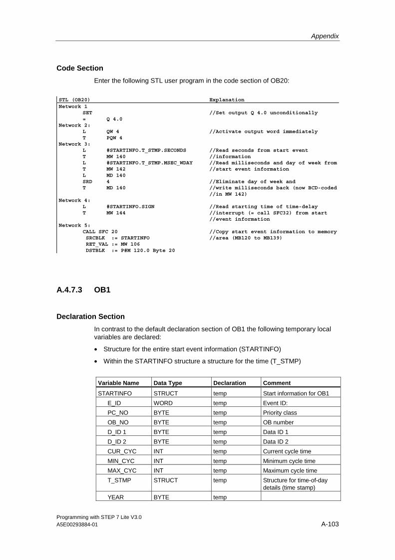
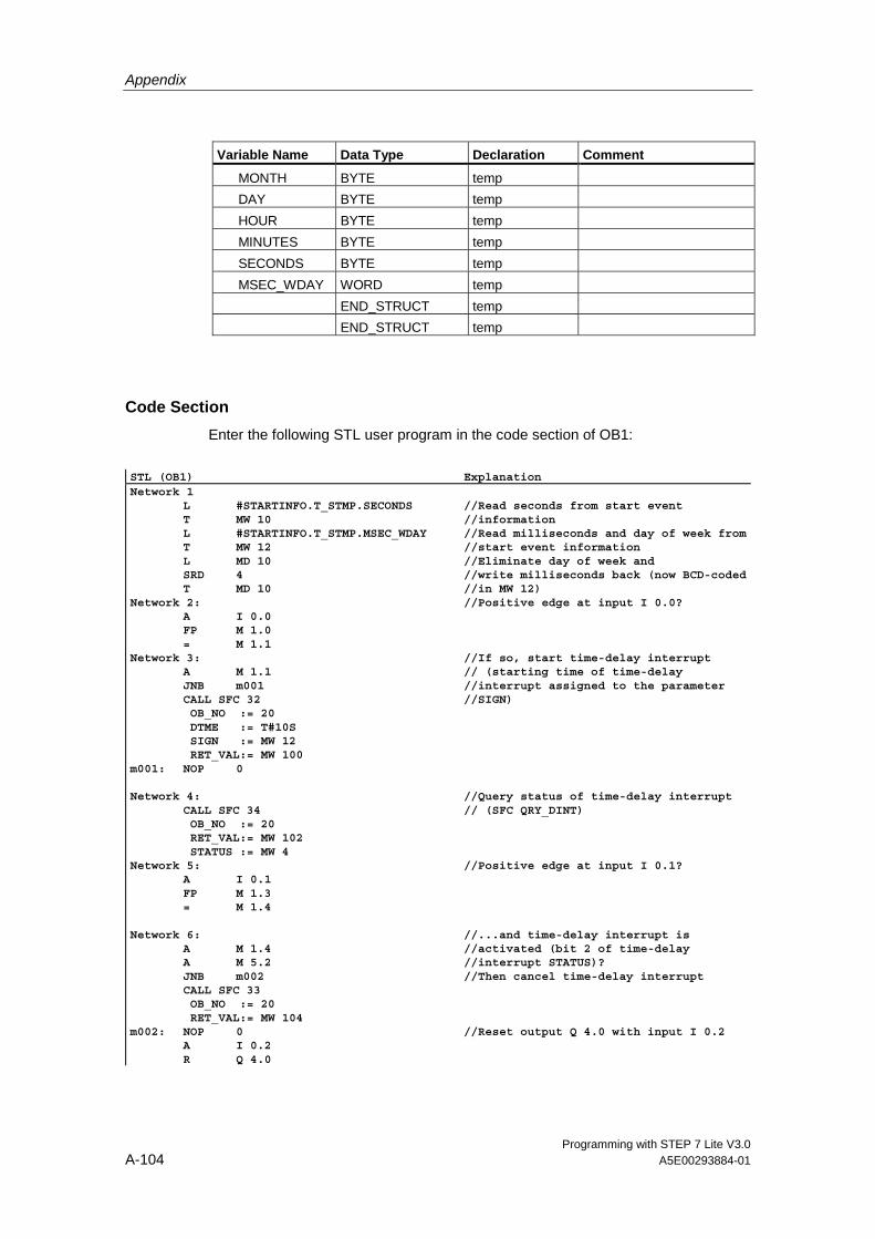
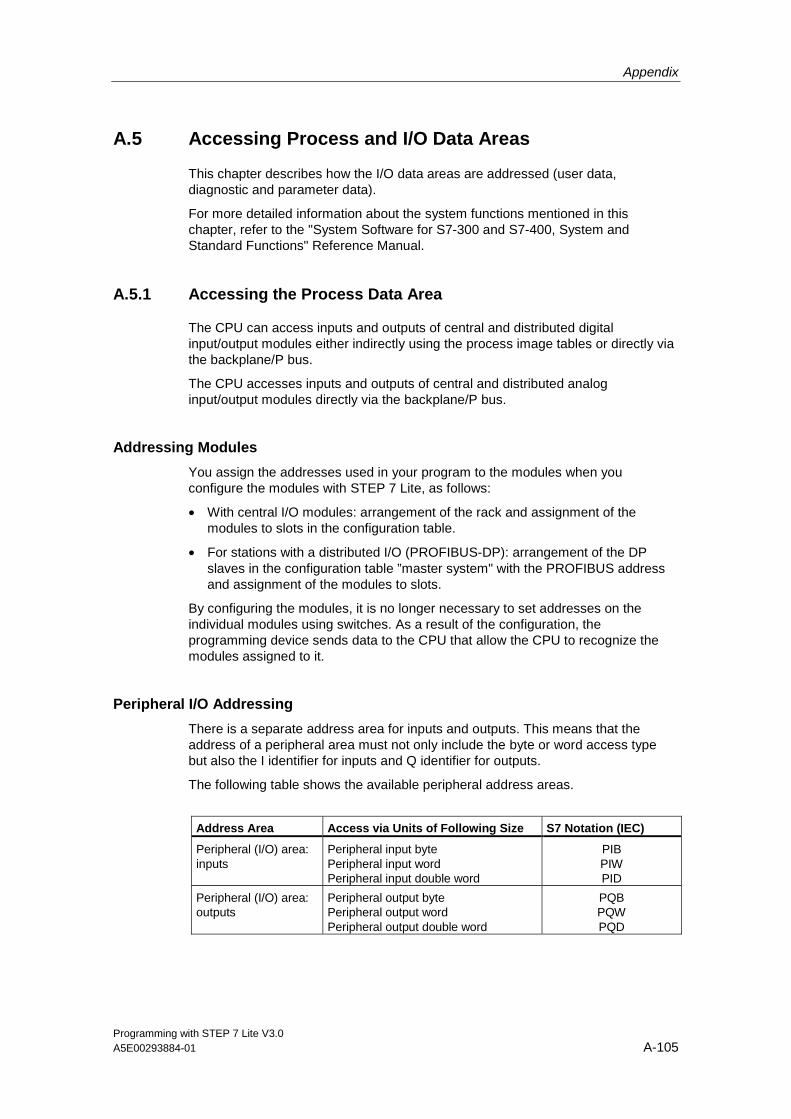
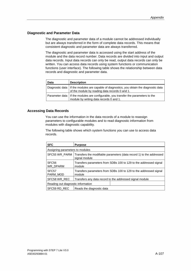
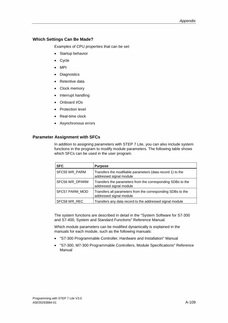
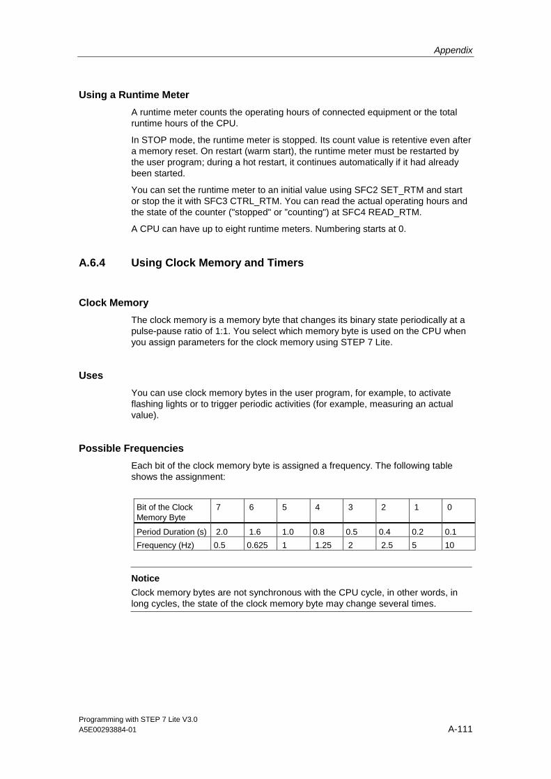


![Simatic Step 7 Lite [v3.0]](https://static.documents.pub/doc/80x56/55256fda5503468e6e8b4824/simatic-step-7-lite-v30.jpg)


