51
Applikationen & Tools Answers for industry. Cover Print Standard Add-On TM41 SIMOTION & SINAMICS Application description January 2016

Applikationen & Tools
Answers for industry.
Cover
Print Standard Add-On TM41
SIMOTION & SINAMICS
Application description � January 2016

2Print Standard Add-On TM41
V3.0.1, Item-ID: SIOS-ID: 48956841
Cop
yrig
htã
Sie
men
sA
G20
16A
llrig
hts
rese
rved
Siemens Industry Online SupportThis article is taken from the Siemens Industry Online Support. The following linktakes you directly to the download page of this document:http://support.automation.siemens.com/WW/view/en/48956841
CautionThe functions and solutions described in this article confine themselves to therealization of the automation task predominantly. Please take into accountfurthermore that corresponding protective measures have to be taken up in thecontext of Industrial Security when connecting your equipment to other parts of theplant, the enterprise network or the Internet. Further information can be foundunder the Item-ID 50203404.http://support.automation.siemens.com/WW/view/en/50203404
You can also actively use our Technical Forum from the Siemens Industry OnlineSupport regarding this subject. Add your questions, suggestions and problems anddiscuss them together in our strong forum community:http://www.siemens.com/forum-applications

Print Standard Add-On TM41V3.0.1, Item-ID: SIOS-ID: 48956841 3
Cop
yrig
htã
Sie
men
sA
G20
16A
llrig
hts
rese
rved
s
SIMOTIONPrint Standard Add-On TM41V3.0.1
Application description 1
Application structure 2
Integration 3
Function description 4
Commissioning 5Use of the exampleapplication 6
Abbreviations 7
Related Literature 8
Version History 9
Contact 10

Warranty and liability
4Print Standard Add-On TM41
V3.0.1, Item-ID: SIOS-ID: 48956841
Cop
yrig
htã
Sie
men
sA
G20
16A
llrig
hts
rese
rved
Warranty and liabilityNote The Application Examples are not binding and do not claim to be complete
regarding the circuits shown, equipping and any eventuality. The ApplicationExamples do not represent customer-specific solutions. They are only intendedto provide support for typical applications. You are responsible for ensuring thatthe described products are used correctly. These application examples do notrelieve you of the responsibility to use safe practices in application, installation,operation and maintenance. When using these Application Examples, yourecognize that we cannot be made liable for any damage/claims beyond theliability clause described. We reserve the right to make changes to theseApplication Examples at any time without prior notice.If there are any deviations between the recommendations provided in theseapplication examples and other Siemens publications – e.g. Catalogs – thecontents of the other documents have priority.
We do not accept any liability for the information contained in this document.
Any claims against us – based on whatever legal reason – resulting from the use ofthe examples, information, programs, engineering and performance data etc.,described in this Application Example shall be excluded. Such an exclusion shallnot apply in the case of mandatory liability, e.g. under the German Product LiabilityAct (“Produkthaftungsgesetz”), in case of intent, gross negligence, or injury of life,body or health, guarantee for the quality of a product, fraudulent concealment of adeficiency or breach of a condition which goes to the root of the contract(“wesentliche Vertragspflichten”). The damages for a breach of a substantialcontractual obligation are, however, limited to the foreseeable damage, typical forthe type of contract, except in the event of intent or gross negligence or injury tolife, body or health. The above provisions do not imply a change of the burden ofproof to your detriment.
Any form of duplication or distribution of these Application Examples or excerptshereof is prohibited without the expressed consent of Siemens Industry Sector.

Preface
Print Standard Add-On TM41V3.0.1, Item-ID: SIOS-ID: 48956841 5
Cop
yrig
htã
Sie
men
sA
G20
16A
llrig
hts
rese
rved
PrefaceTarget
This document describes the use and the parameterization of the SINAMICSdevice TM41 in SIMOTION mode in combination with the SIMOTION standardapplication Print Standard.It shows the user in an easy way how to use the TM41 especially for solutionswithin printing presses.
Target ReadersThis document applies to programmers and application engineers.
Main ContentsThe main purpose of this application is to describe the basic functionality andparameterization of the TM41. It shows exemplary how to integrate the TM41 in theright way in an existing machine set point concept.
LimitationsThis document does not include a description of SIMOTION and SINAMICS ingeneral. General knowledge of· SCOUT· SIMOTION· SINAMICS· Application Print StandardAnd the available standard product documentation is necessary
Scope of supplyPrint Standard Add-On TM41 is available for download on the customer supportwebsite at applications. The scope of supply contains:- Scout Project: Print Standard Add-On TM41 V3.0.0.zip- Documentation Print Standard Add-On TM41 V3.0.0_en.pdf (this document)

Table of contents
6Print Standard Add-On TM41
V3.0.1, Item-ID: SIOS-ID: 48956841
Cop
yrig
htã
Sie
men
sA
G20
16A
llrig
hts
rese
rved
Table of contentsWarranty and liability ............................................................................................... 4Preface ...................................................................................................................... 5
Target Readers .................................................................................. 5Main Contents ................................................................................... 5Limitations ......................................................................................... 5Scope of supply ................................................................................. 5
1 Application description .................................................................................. 7
1.1 Basic information and data................................................................. 71.1.1 System requirements ......................................................................... 71.1.2 SINAMICS TM41 device basic information ......................................... 71.1.3 SINAMICS and SIMOTION mode ...................................................... 81.2 Concept of Print Standard Add-On TM41 ........................................... 81.2.1 Overview ........................................................................................... 81.2.2 Different use cases of TM41 in printing machine concepts ................. 8
2 Application structure.................................................................................... 103 Integration..................................................................................................... 12
3.1 Integration to a machine project ....................................................... 123.2 Integration of the SINAMICS DO ...................................................... 133.3 Integration of the SIMOTION Axis TO .............................................. 173.4 Integration of software functionality .................................................. 21
4 Function description .................................................................................... 25
4.1 Overview ......................................................................................... 254.2 Unit fTM41 “FBTM41Backgr” ........................................................... 264.3 Unit pRA_TM41_Infeed ................................................................... 32
5 Commissioning ............................................................................................ 33
5.1 General information about TM41 ...................................................... 335.2 Basic settings of TM41 in SINAMICS mode (P4400=1) .................... 355.3 Basic settings of the TM41 in SIMOTION mode (p4400=0) .............. 365.3.1 Use Case 1 SIMOTION Mode .......................................................... 365.3.2 Use Case 2 SIMOTION Mode .......................................................... 375.3.3 Application/use case depending parameters .................................... 385.3.4 Check of SIMOTION parameterization in use case 1........................ 39
6 Use the example application ........................................................................ 447 Abbreviations ............................................................................................... 488 Related literature .......................................................................................... 49
8.1 Bibliography..................................................................................... 498.2 Internet link specifications ................................................................ 49
9 Version History ............................................................................................. 5010 Contact.......................................................................................................... 51

1 Application description
Print Standard Add-On TM41V3.0.1, Item-ID: SIOS-ID: 48956841 7
Cop
yrig
htã
Sie
men
sA
G20
16A
llrig
hts
rese
rved
1 Application descriptionThis application could be used in every printing press application with TM41 pulseencoder emulation for a register control system or a separate machine modulewhich gets the encoder signal as real master leading value.
1.1 Basic information and data
1.1.1 System requirements
This application was developed and tested using:
● SIMOTION SCOUT 4.4 HF 6
● SIMOTION CF card Firmware V4.4.0.6: D4x5_2_V47
d4x5_2_v47.zip [This Firmware includes for Sinamics Integrated: SINAMICSV4.7.x.x (Int. Identifier 79.11.22.00) for Sinamics integrated]
● SIMATIC STEP 7 V5.5 + SP4 + HF5
● SIMOTION D435 training case TK-SIM-D435 built by SITRAIN
(MLFB: 6ZB2470-0AE00) to be connected to 1 AC 230 V or 1AC 115 Vwith transformer, equipped with:Additional SIMOTON D435-2 DP/PN (MFLB: 6AU1 435-2AD00-0AA0)SLM 5kW, Double Motor Module 3A, 2 Synchronous Motors:1FK7022-5AK71-1AG0 (2048 sin/cos incremental with SMC20)1FK7022-5AK71-1LG0 (512 multi turn absolute with DRIVE-CLiQ)
● TM41 device (MFLB : 6SL3055-0AA00-3PA1)
1.1.2 SINAMICS TM41 device basic information
With the TM41 machine module a master position (set value) can be given as anincremental encoder signal to another controller or to a register control system.To realize the coupling to the respective reference axis the TM41 can be used inSINAMICS or SIMOTION mode.In SINAMICS mode the TM41 works as an actual value coupling to a referenceaxis (P4400=1). If using it in SINAMICS pay special attention to chapter 3.1In SIMOTION mode the TM41 works as a set point coupling to another SIMOTIONaxis. The position set value of the reference axis will be issued on the incrementalencoder interface. The axis can be used as a gearing axis, the movement will besynchronized to the motion of the set value.The incremental encoder interface X520 is shown on picture 1-1.
NOTE General information about the TM41 is available in the SINAMICS manual (GH1)04/2014.

1 Application description
8Print Standard Add-On TM41
V3.0.1, Item-ID: SIOS-ID: 48956841
Cop
yrig
htã
Sie
men
sA
G20
16A
llrig
hts
rese
rved
Figure 1-1 Incremental encoder interface
1.1.3 SINAMICS and SIMOTION mode
Generally the TM41 could be used in SIMOTION or SINAMICS mode. In printingapplications it will be used mostly in the SIMOTION mode.If only the encoder signal of a real axis is necessary without influencing this valuein any way the SINAMICS mode is sufficient. The TM41 will be coupled fix to theactual value of the respective axis. This requires that the real axis drive object andthe TM41 are placed on the same SINAMICS control unit.The SIMOTION mode offers a more flexible use of the TM41. The extendedfunctionalities are:
● Synchronization to different masters on different controllers (same behavior asa standard gearing axis)
● Synchronization to the master with gearing functionality
● Synchronization to virtual axis to provide an optimal leading value for othermachine modules
1.2 Concept of Print Standard Add-On TM41
1.2.1 Overview
The application should give a clear and easy overview how to integrate the TM41to a Print Standard based machine software concept. The main points are· Integration to the SINAMICS and SIMOTION part of the project· Parameterization of SINAMICS· Setting of configuration data and system variables in SIMOTION· Control the TM41 by the software· Check the outgoing signals
1.2.2 Different use cases of TM41 in printing machine concepts
In standard machine concepts the TM41 can be integrated in two different ways:
● Response value for a register control system

1 Application description
Print Standard Add-On TM41V3.0.1, Item-ID: SIOS-ID: 48956841 9
Cop
yrig
htã
Sie
men
sA
G20
16A
llrig
hts
rese
rved
● Leading value for third party machine modules (outside the Simotion/Sinamicssystem)
In earlier machine concepts both use cases were often realized by a mechanicalcoupling with an external encoder on the reference axis.Picture 1-2 shows both use cases exemplarily on a printing machine. On one handthe TM41 gives the response of the printing cylinder set position to a registercontrol system (use case 1) and on the other hand it could work as the supplier ofthe leading value for following machine module which is not integrated in thepresent machine project.
Figure 1-2 Use cases TM41
The TM41 provides the leading value in an electronical way which has someadvantages in comparison to the mechanical solution.
● A mechanical encoder on the cylinder is not necessary
● Set point coupling is also possible as actual value coupling
● The leading value can be influenced by the project/program
– Gear reduction is possible– Resolution can be directly adapted to the necessary values of the
register control system– The value can be switched between different leading values during
operation (SIMOTION mode)
● No “mechanical wear”-less maintenance due to encoder hardware issues

2 Application structure
10Print Standard Add-On TM41
V3.0.1, Item-ID: SIOS-ID: 48956841
Cop
yrig
htã
Sie
men
sA
G20
16A
llrig
hts
rese
rved
2 Application structureThe example project Print Standard Add-On TM41 based, like all other Add-Onprojects, on the Print Standard basic application. This special Add-On projectcontains all necessary extensions (e.g. variables, function blocks, axis…) to showhow an SINAMICS TM41 hardware device can be integrated to an existing project.Mainly it is intended for projects based on Print Standard application but it is alsopossible to use the functionalities in other projects.The figure 2-1 shows the project axis concept. The functionality of TM41 is toprovide an encoder signal of a virtual master axis or a printing cylinder axis.On SIMOTION side the TM41 is working in the same way like a standardSINAMICS drive. It is coupled to an SIMOTION axis technology object by aPROVIDRIVE standard telegram. Because of that it will be used in the same waylike every other axis also.In the example project at SIMOTION ‘Servo’ the virtual axes VA_LM_WebS,VA_LM_FormatS or the real axis RA_Infeed can be used as master axis for theTM41 axis. It can be switched on the fly from one master to another by changingthe master number on the TM41 STDcIO master number.In most cases the TM41 axis is running stable in gearing on its master setpoint. Ifadditionally functionality like referencing or phase shifting is necessary it need to beprogrammed additionally in the TM41 function block or external.

2 Application structure
Print Standard Add-On TM41V3.0.1, Item-ID: SIOS-ID: 48956841 11
Cop
yrig
htã
Sie
men
sA
G20
16A
llrig
hts
rese
rved
Figure 2-1 Application structure demonstration project
GEARVA_LM_FormatS
Synchronize0 to 360˚
st
RFG
at
v
t
tvt
sPOS
0 to 360˚
st
xy
CAM
GEARRA_Infeed
0 to 360˚
st
RFG
at
v
t
Referencing
Pos.Ctrl.
Kv
0 to 360˚
st
Synchronize
tvt
sPOS
xy
CAM
Referencing
M
DO
Add
0 to 360˚
st
RFG
at
v
t
VA_LM_WebS
tvt
sPOS
0 to 360˚
st
Referencing
Velocity Ctrl.
TnKp
m1
IPO-syncUser Task
IPO System Task
SERVOSystem Task
SINAMICSDrive System
Group Operating Modes:Velocity + Positioning
SuperimposedMotion
Web based
SuperimposedMotion
Color Register
Axis Operating Modes:Velocity + Positioning
Machine Operating Modes:Velocity + Positioning
SuperimposedMotion
0 to 360˚
st
ABS_GEARRA_TM41_Infeed
DO
Pos.Ctrl.
Kv
Interpolator

3 Integration
12Print Standard Add-On TM41
V3.0.1, Item-ID: SIOS-ID: 48956841
Cop
yrig
htã
Sie
men
sA
G20
16A
llrig
hts
rese
rved
3 Integration
3.1 Integration to a machine project
The TM41 will be integrated to the machine project in the same way like a standardaxis. Generally 3 basic steps need to be done to integrate the TM41.
● Integration and parameterization of SINAMICS Drive Object
● Integration and parameterization of SIMOTION TM41 Axis-TO
● Integration of the software functionality to control the TM41 axis
The integration example is based on Print Standard V3.1.3. The TM41 is added tothe “Slave” SIMOTION.

3 Integration
Print Standard Add-On TM41V3.0.1, Item-ID: SIOS-ID: 48956841 13
Cop
yrig
htã
Sie
men
sA
G20
16A
llrig
hts
rese
rved
3.2 Integration of the SINAMICS DO
The TM41 has to be integrated to the SINAMICS part of the project like a standardSINAMIC component. The following table shows the different steps of integration:Figure 3-1 and figure 3-2 is showing the different configuration windows of TM41depending on the selected mode. In SINAMICS mode the setpoint value is directlyconnected to the position actual value of another drive object. In SIMOTION modethe master value is a speed setpoint coming from the PROFIDRIVE telegram.
Table 3-1 Integration of TM41 in SINAMICS
Description
1. Insert a new in/outputcomponent to the respectiveSinamics device.Select device object typeTM41.
2. If no symbolic assignment isused, in the ‘Telegramconfiguration’ the standardtelegram 3 for the TM41device must be chosen andtransfered to the HW-configwith the button ‘Set upaddresses’.
If symbolic assignment isused, this step can beignored.

3 Integration
14Print Standard Add-On TM41
V3.0.1, Item-ID: SIOS-ID: 48956841
Cop
yrig
htã
Sie
men
sA
G20
16A
llrig
hts
rese
rved
Description
3. Under configuration you’llfind the dialogue pulseencoder simulation for theinterface X520 of the TM41.Here the general settings forthe encoder simulationinterface can be done. Acomplete list of allparameters which need to bechange is included to thisdocument at the end of thischapter.
● Simotion/Sinamics mode
● Interpolator ON
● Set point filter
● Dead time
● Encoder data
4. Shift the TM41 device to theused interface of the DriveCLiQ topology in yourproject.If the TM41 should be usedin SINAMICS mode (actualvalue coupling) the basicconfiguration is done here.Last step is to couple therespective axis setpoint tothe position setpoint of TM41(s.figure 3-1)If the TM41 should be usedin SIMOTION mode go onwith further steps explainedin chapter 3.3.
NOTE In SINAMICS it is possible to calculate devices on different Drive CLiQ lines indifferent cycle times. The TM41 in SINAMICS mode need to be calculated in thesame cycle time as its reference axis.
NOTE Only two TM41 in line are permitted on Drive CLiQ

3 Integration
Print Standard Add-On TM41V3.0.1, Item-ID: SIOS-ID: 48956841 15
Cop
yrig
htã
Sie
men
sA
G20
16A
llrig
hts
rese
rved
The following parameters in the TM41 expert list need to be adopted from the basicsetting in the SINAMICS TM41 object.
Table 3-2 Parameterization of SINAMICS object
Parameter Value (in the example project) Description
p408 2048 (value of encoder axisTO RA_Infeed / DODrive_RA_Infeed)
Rotary encoder pulse no.Depending on the respective behavior. In the exampleproject the same value like the reference axis (Blueaxis of the demo case 2048 Inc./rot).Maximum resolution 8192 or 16384 depending on theTM41 hardware version.The TM41 supplies the best results with the highestresolution but this depends on the maximum velocity.More information s. chapter 5.
P418 11 (value of encoder axis TORA_Infeed / DODrive_RA_Infeed)
TM41 fine resolution. In Sinamics mode fine resolutionneed to be the value of the reference axis encoder. Incase of using a virtual axis use the maximumresolution.
P573 YES Inhibit automatic reference calculation
P2000 5000 1/min Reference speedMust be the same like the nominal speed of theSIMOTION axis.
P4400 [0]SIMOTION Incremental encoder operation mode[0]SIMOTION[1]SINAMICS
P4420 Position setpoint r479 (onlySINAMICS mode)
Signal source for incremental encoder emulation inSINAMICS mode (P4400 = 1) s. figure 3-1
P1155 Speed Setpoint r2060[1]Profidrive PZD2+3 (SIMOTIONmode)
Signal source of speed setpoint in SIMOTION mode(P4400 = 0) s. figure 3-2 (presetting by telegram)
NOTE If possible TM41 gives the best results with resolution p408 = 8192/16384Inc./rot and fine resolution p418 = 16Bit. These settings are only possible if thetarget velocity can be reached and the zero mark is not used.

3 Integration
16Print Standard Add-On TM41
V3.0.1, Item-ID: SIOS-ID: 48956841
Cop
yrig
htã
Sie
men
sA
G20
16A
llrig
hts
rese
rved
Figure 3-1 TM41 SINAMICS mode
Figure 3-2 TM41 SIMOTION mode

3 Integration
Print Standard Add-On TM41V3.0.1, Item-ID: SIOS-ID: 48956841 17
Cop
yrig
htã
Sie
men
sA
G20
16A
llrig
hts
rese
rved
3.3 Integration of the SIMOTION Axis TO
If the TM41 is used in SIMOTION mode it will be integrated like a standard axisand it is also working like a SIMOTION axis technology object. The following tableshows the integration steps of the SIMOTION TM41 axis:
Table 3-3 Integration of the SIMOTION axis
Description
1. Create a new SIMOTIONaxis with synchronousoperation functionality.
2. Print Standard settings:
· Axis TypeRotatory and electrical
· Configure unitsIncrements/position:1000000/unit

3 Integration
18Print Standard Add-On TM41
V3.0.1, Item-ID: SIOS-ID: 48956841
Cop
yrig
htã
Sie
men
sA
G20
16A
llrig
hts
rese
rved
Description
3. In the drive assignmentconfiguration connect theaxis to the respective driveobject.In SCOUT Versions > V4.3the alignment of the axis andset up of the drivenormalization parameterscan be done automatically byswitching the axisconfiguration data“TypeOfAxis.DriveControlConfig.dataAdoption” to YES.This parameter can be foundin the expert list.In earlier versions thenormalization has to be donemanually.Proceed until this wizardfinishes.
4. The interconnectionsoverview opens nowautomatically.Mark the possible masterconnections for the followingTO in this mask.Take care of the device (inthis example, use ’Slave’Simotion and not ‘Master’Simotion).

3 Integration
Print Standard Add-On TM41V3.0.1, Item-ID: SIOS-ID: 48956841 19
Cop
yrig
htã
Sie
men
sA
G20
16A
llrig
hts
rese
rved
Description
5. Mark the RA_TM41_Infeedas modulo axis in the‘Mechanics’ mask. (0° ..360°)
6. Save project and compilechanges. If the symbolicassignment is activated, theproper telegram for TM41will be added automaticallyto the Sinamics telegramconfiguration. Otherwise thetelegram (standard telegram3) must be added manually.(see step 2 in chapter 3.2)
The following table contains the configuration data which need to be changed fromthe standard configuration of the TM41 SIMOTION. In the example project a scriptfile with the necessary changes is available (TM41 script folder). Alternatively theconfiguration data can be changed by using the Expert list of the TO.
Table 3-4 TM41-TO configuration
Config-Data Value Description
TypeOfAxis
FineInterpolator [2]CUBIC_MODE Fine interpolator type
NumberOfDataSets.DataSet_1.ControllerStruct.PV_Controller.balanceFilterMode [2]MODE_2 Balancing filter type
NumberOfDataSets.DataSet_1.ControllerStruct.PV_Controller.enableDSC [91]NO DSC activation
NumberOfDataSets.DataSet_1.ControllerStruct.PV_Controller.kpc 100.0 Weighting factor for precontrol
NumberOfDataSets.DataSet_1.ControllerStruct.PV_Controller.kv 100.0 P controller gain
NumberOfDataSets.DataSet_1.ControllerStruct.PV_Controller.preControl [173]YES Activation of precontrol
NumberOfDataSets.DataSet_1.ControllerStruct.conType [PV] Controller type
NumberOfEncoders.Encoder_1.incEncoder.incResolution* 2048 Inc./rev
Number of increments per encoderrevolution. In the example project2048 Inc./rev of axis RA_Infeed

3 Integration
20Print Standard Add-On TM41
V3.0.1, Item-ID: SIOS-ID: 48956841
Cop
yrig
htã
Sie
men
sA
G20
16A
llrig
hts
rese
rved
Config-Data Value Description
NumberOfEncoders.Encoder_1.incEncoder.incResolutionMultiplierCyclic* 2048
Multiplication factor of the cyclicactual value.In the example project 2048 (11Bit)of axis RA_Infeed
NumberOfEncoders.Encoder_1.FrequencyLimit 1024000 HzFrequency limit of the measuringsystem. Depends on the TM41hardware version
SetPointDriverInfo.DriveData.nominalSpeed* 5000 1/minSpecification of the referencespeed. In the example project 50001/min (p2000 of the SINAMICS DO)
DriveControlConfig.dataAdaption YES
Activation of drive adaptionSIMOTION > V4.3 Automaticadaption of nominal values atSIMOTION TO Axis(e.g. nominal speed, encoderdata…)Note: for automatic data adoptionthe configuration dataSetPointDriverInfo.DriveData.torqueReference need to beNOMINAL_VALUE
*Adoption not necessary in case of using the automatic data adoption (SCOUTVersion >= V4.3)
NOTE To make the parameterization of the SIMOTION axis easier the TM41 axis in theexample project is equipped with an example script, which automatically sets allimportant parameters.

3 Integration
Print Standard Add-On TM41V3.0.1, Item-ID: SIOS-ID: 48956841 21
Cop
yrig
htã
Sie
men
sA
G20
16A
llrig
hts
rese
rved
3.4 Integration of software functionality
To use the TM41 in SIMOTION mode the integration of a software part isnecessary to control the TM41 axis. In the example project a function block with thebasic functionality is integrated. It contains gearing and e-stop functionality knownfrom Print Standard. The gearing functionality is working as an absolutesynchronism.The integration of the FB to a machine project is described in a few steps in thefollowing table:
Table 3-5 Integration of software functionality
Description
1. In the example project theTM41 depending softwareparts are completelyintegrated to the SIMOTIONcontroller program part.
fTM41 contains thenecessary data structuresand the motion functionblock.pRA_TM41_Infeedcontains the globalvariables and twoprograms. A start-upprogram for configurationsand a backgroundprogram with the fb call.To integrate the TM41functionality to an existingproject copy the two unitsto the project.
Open the sourcepRA_TM41_Infeed.
2. The interface ofpRA_TM41_Infeed containsthe interface variables, thepossible masters array andthe declaration of the start-up and background program.

3 Integration
22Print Standard Add-On TM41
V3.0.1, Item-ID: SIOS-ID: 48956841
Cop
yrig
htã
Sie
men
sA
G20
16A
llrig
hts
rese
rved
Description
3. In the start-up program thepossible masters array andsome interface variables areassigned.
The possible master array isoptional. It is also possible touse an already existing arraydefined in “dMGlobal” andpreallocate it in “pMStartUp”.
4. In the background programthe FB is defined and called.
5. In the execution systemassign the programpRA_TM41_InfeedStartUp tothe startup Task and thepRA_TM41_InfeedBackgr tothe background task.
6. Additional TM41:After the integration of anadditional SINAMICS DOand SIMOTION TO (seechapter 3.2 and 3.3),duplicate the“pRA_TM41_Infeed” unit andchange the name.The new TO shall be named“RA_TM41_New”. So thenew sources name is“pRA_TM41_New”. Open thenew source.
3 Integration
Print Standard Add-On TM41V3.0.1, Item-ID: SIOS-ID: 48956841 23
Cop
yrig
htã
Sie
men
sA
G20
16A
llrig
hts
rese
rved
Description
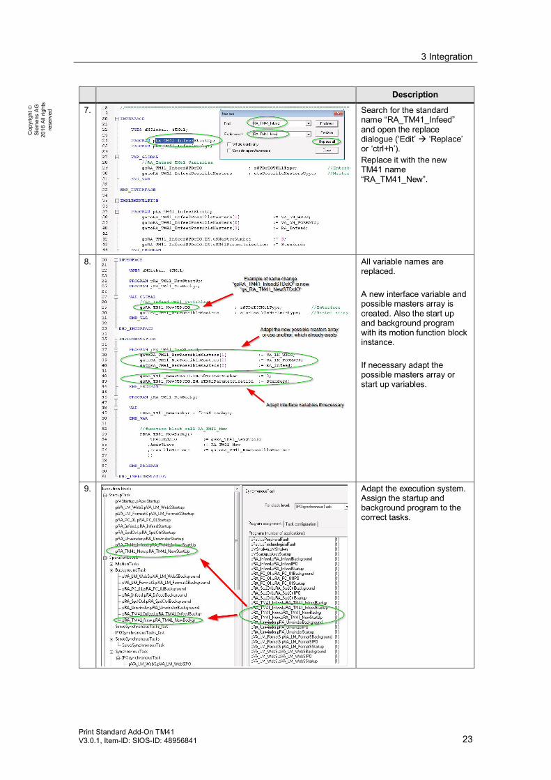
7. Search for the standardname “RA_TM41_Infeed”and open the replacedialogue (‘Edit’à ‘Replace’or ‘ctrl+h’).Replace it with the newTM41 name“RA_TM41_New”.
8. All variable names arereplaced.
A new interface variable andpossible masters array iscreated. Also the start upand background programwith its motion function blockinstance.
If necessary adapt thepossible masters array orstart up variables.
9. Adapt the execution system.Assign the startup andbackground program to thecorrect tasks.

3 Integration
24Print Standard Add-On TM41
V3.0.1, Item-ID: SIOS-ID: 48956841
Cop
yrig
htã
Sie
men
sA
G20
16A
llrig
hts
rese
rved
Description
10. If there are problems withcompiling the unit ‘fTM41’,the compiling setting mightbe adapted.
In this case open the settingsdialogue (‘Options’ à‘settings’ or ‘ctrl+alt+e’) andopen tab ‘Compiler’.
Activate ‘Permit languageextensions’ and save andcompile the project again.

4 Function description
Print Standard Add-On TM41V3.0.1, Item-ID: SIOS-ID: 48956841 25
Cop
yrig
htã
Sie
men
sA
G20
16A
llrig
hts
rese
rved
4 Function description4.1 Overview
The application project contains the necessary extension for the use of TM41device in combination with the Print Standard basic application. The main use caseis to run a SIMOTION axis TO in synchronization with a real or virtual axis.Basically it will be integrated and controlled in the same way like every other PrintStandard axis. The application contains a function block and an interface structurefor TM41.Instead of the Print Standard ‘FBLPrint_MotionAxis’ the TM41 function block dealsonly with two possible modes:
● E_stop [1]: The TM41 axis will be stopped and disabled.
● Gear_mode [60]: The TM41 will be coupled to the selected master axis of themaster array (in standard parametrization).
The following picture shows the TM41 project parts of the project. The axistechnology object, the unit fTM41 contains the function block and the unit pTM41contains the start up and background program.
Figure 4-1 TM41 project parts

4 Function description
26Print Standard Add-On TM41
V3.0.1, Item-ID: SIOS-ID: 48956841
Cop
yrig
htã
Sie
men
sA
G20
16A
llrig
hts
rese
rved
4.2 Unit fTM41 “FBTM41Backgr”
Schematic LAD – RepresentationTable 4-1 scheme of FBTM41Backgr
FBTM41Backgr
FollowingAxis AxisSlave Error BoolatoPossibleMastersType PossibleMasters ErrorID Word
sSTDcIOTM41Type TM41STDcIO
Table 4-2 In- and output parameters of FBTM41Backgr
Name P-Type Type Unit Description
AxisSlave IN FollowingAxis - TM41 TO axisPossibleMasters IN atoPossibleMastersType - Array contains all possible
masters for TM41 presetting instart up task
Error OUT Byte - FB has error. It resetsautomatically, when the causeof error is corrected. Fordetailed information see FBoutput ErrorID
ErrorID OUT WORD - ErrorIDBit 0:Input ‘AxisSlave’ not validBit 1:Following object not valid.Bit 2:‘TM41STDcIO.in.u8MasterNumber’ or‘PossibleMasters’ array not valid(PossibleMasters[u8MasterNumber] = TO#NIL)Bit3:‘TM41STDcIO.in.u8MasterNumber’ out of limitsof PossibleMasters arrayBit4:TO ‘AxisSlave.errorReaction’ <>NONEBit5:Following object of ‘AxisSlave’hast errorReaction <> NONE
TM41STDcIO IN/OUT sSTDcIOTM41Type - TM41 interface, contains masternumber, mode number andgearing settings

4 Function description
Print Standard Add-On TM41V3.0.1, Item-ID: SIOS-ID: 48956841 27
Cop
yrig
htã
Sie
men
sA
G20
16A
llrig
hts
rese
rved
Table 4-3 Structure sSTDcIOTM41Type
Name Type
INu8MasterNumber USINT TM41 Master number from aPossibleMasters arrayu16ModeNumber UINT TM41 motion FB mode number
1: E_Stop60: Gearing
i32Numerator DINT Gear numerator factor (100000)i32Denominator DINT Gear denominator factor (100000)eTM41Parametrization eTM41Para-
metrization-Type
Standard: Use input values for ‘_enableGearing’system function as in the old TM41-AddOnUserDefault: Additional user default input values for‘_enableGearing’ system function are used
boHomeBeforeGearing BOOL If true, the TM41 will be homed before_enableGearing function is called.
OUTu8ActualMasterNumber USINT Actual master numberu16ActualModeNumber UINT Actual mode number
The ‘FBTM41Backgr’ differs between two error types. Error ID bits 0..3 are configerrors. Those errors appear when the configuration is wrong (see errorID in table 4-2). The mode changes at once to ‘E_STOP’. If the error cause is corrected, theerror disappears automatically and the mode switches to‘TM41STDcIO.in.u16ModeNumber’ and the TM41 starts immediately withoperation.
The second error type is thrown by the axis or its following object. If the‘errorReaction’ of the TO is unequal to ‘NONE’, then the error ID bit 4 (axis) oder 5(following object) appears. Mode ‘60’ remains. The TO trys to reset automaticallyas long as a error is existing and the TM41 continues operation, when the errordisappears.
Additional a reset function for the TOs is called, when the internal mode numberchanges (for example due to a config error or the interface input variable‘TM41STDcIO.in.u16ModeNumber’).
CAUTION
If the TM41-TO is restarted, the position of the TO (Simotion) and DO (Sinamics)does not match anymore. This can also happen after a Simotion download. Toavoid this problem, the input ‘TM41STDcIO.in.boHomeBeforeGearing’ must betrue. This activates the homing function before gearing, which adapts the TO- tothe DO-position. This function is called after a mode change (E-Stop à Gearmode) or an axis error.The following settings are required:Number of enoder increments and fine resolution = 2n.
Modulo: 0°..360°Mechanical gear: 1:1

4 Function description
28Print Standard Add-On TM41
V3.0.1, Item-ID: SIOS-ID: 48956841
Cop
yrig
htã
Sie
men
sA
G20
16A
llrig
hts
rese
rved
CAUTION
If the function block input ‘AxisSlave’ will be changed during operation, the newassigned TO will start immediately. The control of the previously assigned TO islost.
If the ‘TM41STDcIO.in.u16ModeNumber’ equals the ‘GEAR_MODE’ the TM41could start anytime! The error reset is automatically!
A change of the master will start at once the synchronization, if the‘GEAR_MODE’ is activated!
If the ‘GEAR_MODE’ is activated and the gearing ratio is adapted(‘TM41STDcIO.in.i32Numerator’ or ‘TM41STDcIO.in.i32Denominator’), the TM41will enable the new factor at once.
The TM41 motion function block uses the ‘_enableGearing’ system function tosynchronize. The synchronization behavior of the axis is influenced much by theinput parameters. The used parameters are explained in the following description.The pre settings are depending on ‘TM41StdcIO.IN.eTM41Parametrization‘.‘Standard’ uses the traditional pre setting parameters as they are used beforeVersion ‘Print Standard AddOn TM41 V300’. ‘UserDefault’ enables additionalconfiguration for the application engineer.
The following list is just an overview of the _enableGearing system functionparameters, which are used and can be changed in this application. For detailedinformation for the system function ‘_enableGearing’ see the pdf‘RefList_SystemFunctions’.
Table 4-4 _enableGearing system function parameter pre setting
Input Value, depending onTM41StdcIO.IN.eTM41Parametrization
Description
direction BY_VALUE The gearing direction is determined from the sign ofthe gear ratio.
gearingType Standard:ABSOLUTE
Gearing is absolute relative to the axis zero for therelevant axes.
UserDefault:USER_DEFAULT
The default setting defined in system variable‘userdefault.gearingSettings.type’ is used.
gearingMode GEARING_WITH_FRACTION
The ratio is specified as a fraction of two integers.
gearingRatioType DIRECT The value set in the 'gearingNumerator' parameter isused as the numerator and the value set in‘gearingDenominator' is used as the denominator.
gearingNumerator Input variable:TM41StdcIO.IN.i32Numerator
Specifies the numerator of the gear ratio.

4 Function description
Print Standard Add-On TM41V3.0.1, Item-ID: SIOS-ID: 48956841 29
Cop
yrig
htã
Sie
men
sA
G20
16A
llrig
hts
rese
rved
Input Value, depending onTM41StdcIO.IN.eTM41Parametrization
Description
gearingDenominator Input variable:TM41StdcIO.IN.i32Denominator
Specifies the denominator of the gear ratio.
synchronizingMode IMMEDIATELY Synchronization takes place immediately.
syncProfileReference RELATE_SYNC_PROFILE_TO_TIME
A synchronization profile specified by the dynamicresponse data is used.
UserDefault:USER_DEFAULT
The default mode setting defined in system variable'userdefault.syncProfile.syncProfileReference' isused.
velocityProfile Standard:TRAPEZOIDAL
This value defines the velocity profiledirectly.
UserDefault:USER_DEFAULT
The default velocity profile defined in system variable'userDefault.syncDynamics.profile' is used.
synchronizingWithLookAhead
USER_DEFAULT The default setting defined in system variable'userDefault.gearingSettings.synchronizingWithLookAhead' is used
synchronizingDirection USER_DEFAULT The default setting defined in system variable'userDefault.gearingSettings.synchronizingDirection'is used.
mergeMode IMMEDIATELY The synchronous operation motion replaces all activeslave axis motions. In the event that there are alreadytwo commands to be processed, the waiting or lastprogrammed command as well as any command inthe command buffer are cancelled.
nextCommand WHEN_BUFFER_READY
The transition takes place after the command isentered in the command queue.
Parameters marked with ‘USER_DEFAULT’ can be configured in the default maskof the synchronous operation object.

4 Function description
30Print Standard Add-On TM41
V3.0.1, Item-ID: SIOS-ID: 48956841
Cop
yrig
htã
Sie
men
sA
G20
16A
llrig
hts
rese
rved
The next table shows which variables can be changed depending on thepreconfigured mode in interface variable ‘TM41StdcIO.IN.eTM41Parametrization‘.
All ‘_enableGearing’ input parameters, which are not in the list, are using theSimotion default parameters. For more information about the default adjustmentand the effects use the documentation ‘RefList_SystemFunctions’.
Table 4-5 Default parameters for synchronization
Description
1. To adapt default parameters,expand the respective TM41synchronous operationobject and double-click‘Default’.
2. In the tab ‘gearing’ twoparameters can be adapted.GearingType (valid for:eTM41Parametrization =UserDefault).synchronizingWithLookAhead’: (valid for:eTM41Parametrization =Standard or UserDefault).
3. In the tab ‘gearsynchronization’ oneparameter can be adapted.SynchronizingDirection (validfor:eTM41Parametrization =UserDefault).

4 Function description
Print Standard Add-On TM41V3.0.1, Item-ID: SIOS-ID: 48956841 31
Cop
yrig
htã
Sie
men
sA
G20
16A
llrig
hts
rese
rved
Description
4. In the tab ‘dynamicresponse’ the followingparameters can be adapted:VelocityProfile (valid for:eTM41Parametrization =UserDefault).syncProfileReference (validfor:eTM41Parametrization =UserDefault).
The ‘Time-relatedsynchronization’ or ‘Master-value-relatedsynchronization’-parametersare used for synchronizingprocess, depending on‘syncProfileReference’.If the trapezoidal velocityprofile is selected, the jerk isignored. (WitheTM41Parametrization =Standard the ‘Velocity profile’is pre-set with ‘trapezoidal’and the ‘Profile specification’with ‘relate sync profile totime’)

4 Function description
32Print Standard Add-On TM41
V3.0.1, Item-ID: SIOS-ID: 48956841
Cop
yrig
htã
Sie
men
sA
G20
16A
llrig
hts
rese
rved
4.3 Unit pRA_TM41_Infeed
The global variables of this source contains the STDc interface of the TM41 axisand a possible masters array. The last one is not necessary. Another one, whichalready exists in the ‘dMGlobal’ of print standard can also be used for the“fbTM41Backgr” function block. It has the same data type as the print standardfunction block.
Program “pRA_TM41_InfeedStartup” is called in the start up task. It contains initialvalues for the interface or the possible masters array.
Program “pRA_TM41_InfeedBackgr” for the function block call “FBTM41Backgr”need to be called in the Background Task.
Figure 4-2 pTM41Backgr

5 Commissioning
Print Standard Add-On TM41V3.0.1, Item-ID: SIOS-ID: 48956841 33
Cop
yrig
htã
Sie
men
sA
G20
16A
llrig
hts
rese
rved
5 Commissioning5.1 General information about TM41
The maximum resolution and the maximum frequency of the TM41 depend on thehardware version:Module 6SL3055-0AA00-3PA0:
● p408 max. value = 8192 bar/rot
● fmax.[kHz] = 256
Module 6SL3055-0AA00-3PA1:
● p408 max value = 16384 bar/rot
● fmax.[kHz] = 512 (1024kHz)
From hardware version C the maximum frequency can be increased to 750kHz or1024kHz by using parameter 4401.7.If the maximum frequency of the device will be reached the reaction of the DriveObject will be the fault F35220 the frequency is limited to fmax.Depending on fmax the maximum velocity nmax will be calculated to:nmax =f(numbers of bars)nmax =fmax /(Number of bars per rotation)*60*1/min
E.g. for the module 6SL3055-0AA00-3PA0:8192 bars/rotnmax =256000 / 8192 * 60 = 1875 1/min1875 1/min is the maximum velocity value of the TM41 if the highest resolution of8192 bars/rotation is used.This means for the SIMOTION axis a maximum velocity ofvmax SIMOTION = nmax * 360° / 60s = 11250°/s
A basic difference between SIMOTION and SINAMICS mode is that in SIMOTIONmode the TM41 gets a velocity set point from the SIMOTION position controllerfrom the internal PROFIBUS system. The position set point of SIMOTION will becalculated to a speed set point which will be send to the SINAMICS (closed loopcontrolled).In SINAMICS mode the TM41 gets the actual position of the reference axis asleading value (controlled operation).

5 Commissioning
34Print Standard Add-On TM41
V3.0.1, Item-ID: SIOS-ID: 48956841
Cop
yrig
htã
Sie
men
sA
G20
16A
llrig
hts
rese
rved
SINAMICS TM41 Parameter p4401Depending on hardware and SINAMICS version additional setting on theSINAMICS device can be used. From SINAMICS V4.5 additional functionalities onp4401 can be used. The following table explains these settings in detail.
Table 5-1 SINAMICS Parameter p4401
Bit Signal 1-Signal
0-Signal
Description
0 Zeromark enable Yes No When the TM41 is operated in theSINAMICS mode (p4400 = 1), thefollowing applies:A new zero mark search is initiatedby switching in the zero mark at theTM41 (p4401.0 = 1). The zero markis outputat the TM41 as soon as it wassynchronized with the zeroposition/zero mark of the leadingencoder.
1 Zero marks synchronized with zeropositionof absolute encoders
Yes No For p4401.1 = 1, the followingapplies:The zero pulse is only output viaX520 when the absolute encoderpasses the zero position of theabsolute position(modulo converted).For p4401.1 = 0, the followingapplies:The zero pulse is output via X520compatible with previous firmwareversions (< V4.3). The zero pulse isoutputwhen the TM41 (modulo converted)passes the position it was in whenthe 24 V supply was switched on.
4 Activate higher actual valueresolution
Yes No 32 Bit actual value resolution
5 Activate higher setpoint resolution Yes No 32 Bit setpoint resolution6 Deactivate residual value handling
in the setpoint channelYes No
7 Activate output frequencies greaterthan 750 kHz
Yes No For hardware versions A and B, this bithas no significance (output frequency =512 kHz).For p4401.7 = 0, the following applies:The maximum output frequency is 750kHz (from hardware version C).For p4401.7 = 1, the following applies:The maximum output frequency is 1024kHz (from hardware version C).

5 Commissioning
Print Standard Add-On TM41V3.0.1, Item-ID: SIOS-ID: 48956841 35
Cop
yrig
htã
Sie
men
sA
G20
16A
llrig
hts
rese
rved
5.2 Basic settings of TM41 in SINAMICS mode (P4400=1)
In SINAMICS mode a direct actual position value coupling to a SINAMICS DO willbe realized. The following picture shows how the TM41 will be coupled to themaster value.
Figure 5-1 Parameterization SINAMICS mode
The TM41 will take directly the position actual value from the reference axis. Incase of the example project this is the position actual value (r479) from theDrive_RA_Infeed (If the TM41 will be switched to SINAMICS mode).The parameter p408 should be the same like the reference axis. The p418(multiplier) has to be the same value like the connected encoder in p4420 of thereference axis. Otherwise the zero marks are not synchronized and the velocity willnot match the velocity of the connected encoder.The multiplied value is only an internal factor. On the interface –X521 of TM41 onlyincrements of p408 will be dispensed.
CAUTION
The SINAMICS mode is acting as an actual value coupling with thecorresponding effects.
Dead time compensationOn the encoder emulation of the TM41 a dead time compensation is available also(s. figure 5-1).The encoder set point will be shift with this multiplier (p4421) velocity depending.P4421 = 0: Dead time compensation switched offP4421 <> 0: Actual value = p4420 + Delta s *4421Delta s: Change of position per cycle (4099[3])

5 Commissioning
36Print Standard Add-On TM41
V3.0.1, Item-ID: SIOS-ID: 48956841
Cop
yrig
htã
Sie
men
sA
G20
16A
llrig
hts
rese
rved
5.3 Basic settings of the TM41 in SIMOTION mode(p4400=0)
The TM41 in SIMOTION mode will be considered like a real axis whose positionset point will be output on the incremental encoder emulation of the TM41.The output is synchronized to the movement of the leading value. As leadingvalues e.g. other technology objects like virtual master axis, real axis, externalencoders can be chosen.It works like a standard SIMOTION axis. To correct position differences a positioncontroller will be used on the return value.The TM41 in SIMOTION mode can act in two different use cases. Below both usecases are described separately.
5.3.1 Use Case 1 SIMOTION Mode
The figure 5-2 shows the functionality of the TM41 in use case 1. The positionshould be equal to the position of the reference axis. The figure below shows thisuse case. The TM41 is directly coupled to the real axis e.g. to supply the exactposition of a printing cylinder PC_02 to a register control system.The TM41_PC_02 axis is getting its command position from the RA_PC_02 axis.
Figure 5-2 Use case 1

5 Commissioning
Print Standard Add-On TM41V3.0.1, Item-ID: SIOS-ID: 48956841 37
Cop
yrig
htã
Sie
men
sA
G20
16A
llrig
hts
rese
rved
5.3.2 Use Case 2 SIMOTION Mode
Figure 5-3 shows the TM41 in use case 2. The TM41 is sending a leading valuefrom one machine module to another. In this case the leading value could be a realaxis or a virtual axis. The second controller could be a SIMOTION or anothersystem. In case of SIMOTION/SINAMICS the leading value from TM41 is receivedas an external encoder value and will be connected to an SMC30.If two machine modules are coupled it is important to extrapolate the leading valueto compensate dead times which come from the bus communication or internaltimes of the systems. Otherwise velocity depending position differences will occur.With extrapolation the position value will be calculated to a further positiondepending on the system and the actual velocity.For this case the actual value of TM41 needs to be delayed by one servo cycle ofcontroller 1:DynamicComp.DeadTime = TservoAlso the leading value (external encoder) of the axis on the second controllerneeds to be extrapolated (The time values need to be taken from the secondcontroller configuration):text = 2 x tipo + tdp + ti + to+ tel
This time need to be entered to the extrapolation time of the external encoder ofcontroller 2. Simotion: TypeOfAxis.extrapolation.extrapolationTime.
NOTE The calculation of the extrapolation time can also be done with the tool on theutilities and application DVD of SIMOTION.More information about extrapolation settings s. FAQ TM41
Figure 5-3 Use Case 2

5 Commissioning
38Print Standard Add-On TM41
V3.0.1, Item-ID: SIOS-ID: 48956841
Cop
yrig
htã
Sie
men
sA
G20
16A
llrig
hts
rese
rved
The general settings for the TM41 were explained in the integration part forSIMOTION in chapter 3. Some parameters need to be adapted to the respectiveapplication.
5.3.3 Application/use case depending parameters
Table 5-2 Use case depending parameters
Parameter/Config-Data
Value (Exampleproject)
Description
p408 2048 (value ofencoder axisDrive_RA_Infeed)
Rotary encoder pulse no.Depending on the respective behavior. In the exampleproject the same value like the reference axis (Blue axis ofthe demo case 2048 Inc. /rot).Maximum resolution 8192 or 16384 depending on the TM41device.The TM41 supplies the best results with the highestresolution but this depends on the maximum velocity.
P418 11 (value ofencoder axisDrive_RA_Infeed)
TM41 fine resolution. The fine resolution need to be thevalue of the reference axis encoder. In case of using a virtualaxis use the maximum resolution.
NumberOfEncoders.Encoder_1.incEncoder.incResolution
2048 Inc./rev Number of increments per encoder revolution. Need to bethe value of the respective reference axis. In the exampleproject 2048 Inc./rev of axis RA_Infeed
NumberOfEncoders.Encoder_1.incEncoder.incResolutionMultiplierCyclic
2048 Multiplication factor of the cyclic actual value. Need to be thevalue of the respective reference axis. In the example project2048 (11Bit) of axis RA_Infeed
NumberOfDataSets.DataSet_1.DynamicComp.Enable
[YES] Activation of dynamic response compensationOnly necessary in case of using SIMOTION < V4.2 to usethe dead time compensation.
NumberOfDataSets.DataSet_1.DynamicComp.DeadTime
0.000s In SIMOTION >= V4.2 value need to be 0.0ms, in earlierversion it need to be 1 DP-Cycle e.g. in the example project3ms
TypeOfAxis.extrapolation.extrapolationTime
- Extrapolation time on the external encoder on the secondcontroller. (Attention: this is not a parameter of the TM41)

5 Commissioning
Print Standard Add-On TM41V3.0.1, Item-ID: SIOS-ID: 48956841 39
Cop
yrig
htã
Sie
men
sA
G20
16A
llrig
hts
rese
rved
5.3.4 Check of SIMOTION parameterization in use case 1
To check the correct behavior of the TM41 device, an analysis with the SIMOTIONtrace is possible as well as an analysis with an external device like an oscilloscope.
SIMOTION Trace analysisFor the most applications an analysis of the actual values in SIMOTION issufficient.The picture 5-4 below shows the behavior of the TM41 following an ideal real axis.In this case the actual position of TM41 and the real axis are matching each other(s. curve TM41/referenceaxis.sensordata.position). Both values are two cycles laterthan the commandposition (curve positioningstate.commandposition). The pictureshows the modulo-change from 360° to 0°.The two cycles between command- and actualposition follow from the systeminternal processing behavior.
Figure 5-4 SIMOTION Trace analysis
In most cases the dynamic/mechatronic behavior of the real axis (e.g. printingcylinder) is not ideal. Because of that an adoption to the real mechanical behaviorsis necessary also on TM41 site.In SIMOTION < V4.2 additionally one DP-cycle dead time compensation isnecessary. (DynamicComp.DeadTime)
Table 5-3 Commissioning steps SIMOTION trace
1. If TM41 is integrated like described in chapter 2 adopt the Sinamics parameters (p408, p418,p573, p2000)
2. Adopt the following SIMOTION parameters of the script file to your project values:(NumberOfDataSets.DataSet_1.DynamicComp.deadTime - > 1 DP-cycle if SIMOTION < V4.2)NumberOfEncoders.Encoder_1.incEncoder.incResolutionNumberOfEncoders.Encoder_1.incEncoder.incResolutionMultiplierCyclicNumberOfEncoders.Encoder_1.FrequencyLimit -> Depending on deviceSetPointDriverInfo.DriveData.nominalSpeed -> = p2000 SINAMICS
3. Run reference axis with slow speed and make a trace of (TM41 need to be in synchronism):TM41.sensordata[1].position

5 Commissioning
40Print Standard Add-On TM41
V3.0.1, Item-ID: SIOS-ID: 48956841
Cop
yrig
htã
Sie
men
sA
G20
16A
llrig
hts
rese
rved
Axis.sensordata[1].position
4. Zoom deep In the position trace (same scaling) and check if positions match.Adopt the dead time that the positions will match as good as possible. (s.figure 5-4)
SINAMICS Trace analysisIt is also possible to check the TM41 zero mark and real axis zero mark with theSINAMICS trace.To do this it is necessary to integrate a SMC30 to read in the TM41 output.Furthermore the TM41 (SUB-D output) and SMC30 (Terminal input) need toconnect by a measuring cable.The following pictures show the interfaces of SMC30 and TM41. The pins A, A*, B,B*, R, R* and M needs to be connected.
Figure 5-5 SMC30 X521/X531 Interfaces

5 Commissioning
Print Standard Add-On TM41V3.0.1, Item-ID: SIOS-ID: 48956841 41
Cop
yrig
htã
Sie
men
sA
G20
16A
llrig
hts
rese
rved
Figure 5-6 TM41 X520 Interface
To trace the zero marks the following needs to be configured:
Zero mark of real axis encoder:- Set p496[0] in the expert list of the drive to [23] – r0497: Zero mark status
Zero mark of TM41:- Set p496 in the expert list of the SMC30 to [23] – r0497: Zero mark status
NOTE Parameter p496 is an access level 4 parameter!
NOTE The parameter p496 needs to be set again after power off.
After the settings above the zero mark status can be traced using the parameterr497.
Oscilloscope analysisIn case of using a real axis with encoder connection by SMC20 it is also possible tocheck the right TM41 configuration by comparing the zero marks of axis and TM41with an external measuring system e.g. an oscilloscope.To do this it is necessary to integrate a measuring cable between encoder andSMC20 – x520 to get the zero impulse from the real motor encoder and use anopen connector on the TM41 – x521 to get the zero pulses of TM41.The following pictures 5-7 and 5-8 show –X520 interface on SMC20 and on TM41.The zero mark pulses R need to be connected to the inputs of the oscilloscope.

5 Commissioning
42Print Standard Add-On TM41
V3.0.1, Item-ID: SIOS-ID: 48956841
Cop
yrig
htã
Sie
men
sA
G20
16A
llrig
hts
rese
rved
Figure 5-7 SMC20 X520 Interface
Figure 5-8 TM41 X520 Interface
If both signals were connected to the oscilloscope the trigger has to be set to thereference axis pulse.If the TM41 is directly coupled to the reference axis the zero marks will only matchif the reference axis was referenced on its zero mark before synchronizationcontroller otherwise a shift between the marks will be there.

5 Commissioning
Print Standard Add-On TM41V3.0.1, Item-ID: SIOS-ID: 48956841 43
Cop
yrig
htã
Sie
men
sA
G20
16A
llrig
hts
rese
rved
If the previous commissioning steps were done correctly (configuration of the axisTO) the zero marks should have a stable distance at different frequencies.Otherwise the configuration should be checked.The following table show again the important parameters and explains how tocompare the axis encoder zero mark and the TM41 zero mark.
Table 5-4 Commissioning of TM41 with oscilloscope
Step
1. If TM41 is integrated like described in chapter 3 adopt the Sinamics parameters (p408, p418,p573, p2000)
2. Adopt the following SIMOTION parameters of the script file to your project values:(NumberOfDataSets.DataSet_1.DynamicComp.deadTime - > 1 DP-cycle if SIMOTION <V4.2)NumberOfEncoders.Encoder_1.incEncoder.resolutionNumberOfEncoders.Encoder_1.incEncoder.resolutionMultiplierCyclicNumberOfEncoders.Encoder_1.FrequencyLimit -> Depending on deviceSetPointDriverInfo.DriveData.nominalSpeed -> = p2000 SINAMICS
3. Connect the measuring cables on SMC 20 and TM41 and connect them to an oscilloscope.
4. Do a referencing to encoder zero mark on the reference axis.
5. Start reference axis with slow speed (TM41 need to be in synchronism) and compare the zeromarks on the oscilloscope. They should be close to each other.
6. Enter different values for the dead time until the zero marks match exactly.
7. Try different speeds, signals should be stable.
Figure 5-9 shows an oscilloscope view of the zero marks. In the picture the zeromarks don’t match exactly. Triangle formed curve is the axis zero mark, pulseformed curve is the TM41 zero mark.
Figure 5-9 Zero marks

6 Use the example application
44Print Standard Add-On TM41
V3.0.1, Item-ID: SIOS-ID: 48956841
Cop
yrig
htã
Sie
men
sA
G20
16A
llrig
hts
rese
rved
6 Use the example applicationFor detailed description how to use the Print Standard axis see the Print Standardmaster documentation. With the described functionality in this document the TM41can be coupled to a Print Standard axis from the PossibleMastersArray. Thefollowing table shows how to synchronize the TM41 to a virtual or real master axis.
Table 6-1
Step Description
1. The TM41 Axis TO isable to synchronize toone of the mastersassigned to the possiblemasters array in thestartup task.In the example projectthe TM41 cansynchronize to theVA_LM_WebS, theVA_LM_FormatS and theRA_Infeed. If other axisare necessary they needto be adopted to thisarray in the startup task
2. For an optimizedoverview the importantvariables to control theapplication are separatedto the watchtable “TM41”.The STDcIO interfaces ofthe Print Standard axesVA_LM_WebS andRA_Infeed are on top ofthe watchtable.After that the statusvariables “syncstate” and“activemaster” of theTM41 following object.At the end the TM41STDcIO and the possiblemasters array

6 Use the example application
Print Standard Add-On TM41V3.0.1, Item-ID: SIOS-ID: 48956841 45
Cop
yrig
htã
Sie
men
sA
G20
16A
llrig
hts
rese
rved
Step Description
3. E.g. Synchronization toVA_LM_WebS:
4. Start VA_LM_WebS byPrint Standard interface
5. Trace analysis, Axisshould be angularsynchronous
6. If a new master axis willbe selected thesynchronization to thenew value starts directly.

6 Use the example application
46Print Standard Add-On TM41
V3.0.1, Item-ID: SIOS-ID: 48956841
Cop
yrig
htã
Sie
men
sA
G20
16A
llrig
hts
rese
rved
Step Description
7. Change synchronizingbehavior:Open ‘Default’ mask of‘RA_TM41_Infeed_SYNCHRONOUS_OPERATION’ and change followingparameters
Tab ‘Gearing’:‘Gear type’ = ‘Relativegear’‘Synchronization withlook ahead’ = ‘Lookahead with s and v’
(If you change theparameters offline, theparameters must bedownloaded first.):
8. Tab ‘Gearsynchronization’ =‘Compatibility mode’
9. Tab ‘Dynamic Response’:‘Profile specification’ =‘Time-relatedsynchronization’‘Velocity profile’ =‘Trapezoidal velocityprofile’
You also can change thesynchronization dynamicin this tab.
10. Change the interfaceparameter‘eTM41Parametrization’to ‘UserDefault’. Now theTM41 has differentsynchronization behavior.(For detailed information,which parameters can beadapted, see chapter 4.2)

6 Use the example application
Print Standard Add-On TM41V3.0.1, Item-ID: SIOS-ID: 48956841 47
Cop
yrig
htã
Sie
men
sA
G20
16A
llrig
hts
rese
rved
Step Description
11. Now the synchronizationis only relative.
CAUTION
If TM41 master value will be change the synchronization starts directly withthe TO RA_TM41_Infeed default values (mask dynamic response).Especially in case of using TM41 as master of real mechanical devices(axes) the following axis need to be decoupled before changing the TM41master. Also in case of using the TM41 as slave axis on a real master axisit should be considered, that the TM41 axis does the same movement as itsmaster.Critical cases are:
· Change of TM41 master axis· Set axis position (referencing)· Change master axis direction by configuration· Error correction in mode ‘60’

7 Abbreviations
48Print Standard Add-On TM41
V3.0.1, Item-ID: SIOS-ID: 48956841
Cop
yrig
htã
Sie
men
sA
G20
16A
llrig
hts
rese
rved
7 Abbreviations
Table 7-1 Abbreviations
Abbreviation Description
TO Simotion Technology objects: Modular motion control firmwaresoftware objects with specific motion functionalities
RA Real Axis: Motion control axis which is connected to a physical drive
VA Virtual Axis: Motion control axis without physical drive connection.
LM Local Master: Virtual Axis (e.g. used to group Real Axes)
GM Global Master: Virtual Axis (e.g. for all Real Axis of the completemachine)
MCC Motion Control Chart : One of the graphical programming languages ofSIMOTION
DO Sinamics Drive Object (e.g. Sinamics axis, TM41 device)

8 Related literature
Print Standard Add-On TM41V3.0.1, Item-ID: SIOS-ID: 48956841 49
Cop
yrig
htã
Sie
men
sA
G20
16A
llrig
hts
rese
rved
8 Related literature
8.1 Bibliography
This list is not complete and only represents a selection of relevant literature.Table 8-1 Related literature
Subject Title1 Print Standard V313 Print Standard V3132 Sinamics Manual
(GH1) 04/2014Sinamics Manual (GH1) 04/2014
3 FAQ TM41Released V1012/2007
FAQ TM41 Released V10 12/2007
8.2 Internet link specifications
This list is not complete and only represents a selection of relevant information.Table 8-2
Subject Title1 Reference to the
entryhttp://support.automation.siemens.com/WW/view/en/EntryID
2 Siemens IndustryOnline Support
http://support.automation.siemens.com
3 Siemens IndustryPrinting
http://www.siemens.com/printing
4 Siemens IndustryAPC
http://www.siemens.com/motioncontrol/apc
5 SIMOTION http://www.siemens.com/simotion
6 SINAMICS http://www.siemens.com/sinamics

9 Version History
50Print Standard Add-On TM41
V3.0.1, Item-ID: SIOS-ID: 48956841
Cop
yrig
htã
Sie
men
sA
G20
16A
llrig
hts
rese
rved
9 Version History
Table 9-1 Version History
Version Date Change
V2.2.1.1 12/2019 createdV2.2.1.2 06/2013 Update to SIMOTION V4.3, update of documentation to new
layoutV3.0.0 11/2015 Update to SIMOTION V4.4,
adaption to Print Standard V3.1.3, bugfixes of fTM41, updateof documentation
V3.0.1 01/2016 Bugfixes / new functions fTM41, update of documentation

10 Contact
Print Standard Add-On TM41V3.0.1, Item-ID: SIOS-ID: 48956841 51
Cop
yrig
htã
Sie
men
sA
G20
16A
llrig
hts
rese
rved
10 Contact
Application Center
SIEMENSSiemens AGDigital FactoryDF FA PMA APCFrauenauracher Str. 8091056 ErlangenFax: 09131-98-1297mailto: [email protected]


