72
SIMOVERT MASTER DRIVES Operating Instructions Part 1 Chassis units (Type K) AC-AC Edition: AB Order No.: 6SE7087-6AK70 www . ElectricalPartManuals . com

SIMOVERT MASTER DRIVES Operating InstructionsPart 1
Chassis units (Type K)AC-AC
Edition: AB Order No.: 6SE7087-6AK70www . El
ectric
alPar
tMan
uals
. com

General 08.97
The reproduction, transmission or use of this document or itscontents is not permitted without express written authority.Offenders will be liable for damages. All rights, including rightscreated by patent grant or registration of a utility model or design,are reserved.
We have checked the contents of this document to ensure thatthey coincide with the described hardware and software.However, differences cannot be completely excluded, so that wedo not accept any guarantee for complete conformance.However, the information in this document is regularly checkedand necessary corrections will included in subsequent editions.We are grateful for any recommendations for improvement. SIMOVERT Registered Trade Mark
Siemens AG 1997 All rights reserved
Overview of the MASTER DRIVES Operating Instructions:
Operating Instructions consists of
Part 1 Part 2
6SE708_-_AD10 6SE708_-_AD70 6SE708_-_XX10
6SE708_-_AD20 6SE708_-_AD70 6SE708_-_XX20
6SE708_-_AD30 6SE708_-_AD70 6SE708_-_XX30
6SE708_-_BD10 6SE708_-_BD70 6SE708_-_XX10
6SE708_-_BD20 6SE708_-_BD70 6SE708_-_XX20
6SE708_-_BD30 6SE708_-_BD70 6SE708_-_XX30
6SE708_-_AH10 6SE708_-_AH70 6SE708_-_XX10
6SE708_-_AH20 6SE708_-_AH70 6SE708_-_XX20
6SE708_-_AH30 6SE708_-_AH70 6SE708_-_XX30
6SE708_-_BH10 6SE708_-_BH70 6SE708_-_XX10
6SE708_-_BH20 6SE708_-_BH70 6SE708_-_XX20
6SE708_-_BH30 6SE708_-_BH70 6SE708_-_XX30
6SE708_-_BM20 6SE708_-_BM70 6SE708_-_XX20
You will receive Parts 1 and 2 of the Operating Instructions when you use this Order No. Parts 1and 2 can be individually ordered by specifying the particular Order No.
_-_ stands for the language code, e.g. 0-0 for German Editions.
The following foreign language Editions of these Operating Instructions are available:
Language German French Spanish Italian
Language code 0-0 7-7 7-8 7-2
These Operating Instructions are valid for software release V1.3.
www . El
ectric
alPar
tMan
uals
. com
08.97 General
Siemens AG 6SE7087-6AK70 0-3SIMOVERT MASTER DRIVES Operating Instructions
Contents
0 Definitions................................................................................................................................. 0-6
0.1 Safety and operating instructions for drive converters ............................................................... 0-8
1 Description................................................................................................................................ 1-1
1.1 Applications ................................................................................................................................ 1-1
1.2 Mode of operation ...................................................................................................................... 1-1
1.3 Operator control- and open-loop control possibilities ................................................................. 1-3
1.4 Block diagram............................................................................................................................. 1-3
2 Transport, Unpacking, Installation ......................................................................................... 2-1
2.1 Transport and unpacking............................................................................................................ 2-1
2.2 Storage....................................................................................................................................... 2-1
2.3 Mounting..................................................................................................................................... 2-2
2.4 Dimension drawing..................................................................................................................... 2-5
3 Connecting-up.......................................................................................................................... 3-1
3.1 Power connections ..................................................................................................................... 3-23.1.1 Protective conductor connection ................................................................................................ 3-43.1.2 DC link connection...................................................................................................................... 3-4
3.2 Auxiliary power supply/main contactor ....................................................................................... 3-4
3.3 Instructions for EMC-correct installation..................................................................................... 3-5
4 Operator control ....................................................................................................................... 4-1
4.1 Operator control elements.......................................................................................................... 4-1
4.2 Displays .................................................................................................................... 4-2
5 Maintenance.............................................................................................................................. 5-1
5.1 Maintenance requirements......................................................................................................... 5-1
www . El
ectric
alPar
tMan
uals
. com

General 08.97
0-4 Siemens AG 6SE7087-6AK70SIMOVERT MASTER DRIVES Operating Instructions
5.2 Replacing components ............................................................................................................... 5-25.2.1 Replacing the fan assembly........................................................................................................ 5-25.2.2 Replacing the fuses (-F101, -F102)............................................................................................ 5-25.2.3 Replacing the fan transformer fuses (-F3, -F4) .......................................................................... 5-35.2.4 Replacing the fan transformer (-T10) ......................................................................................... 5-35.2.5 Replacing the starting capacitor ................................................................................................. 5-35.2.6 Replacing the capacitor bank ..................................................................................................... 5-35.2.7 Replacing SML and SMU ........................................................................................................... 5-35.2.8 Removing and installing the module busbars ............................................................................. 5-45.2.8.1 Replacing the balancing resistor................................................................................................. 5-45.2.9 Replacing boards........................................................................................................................ 5-55.2.9.1 Replacing the IVI ........................................................................................................................ 5-55.2.9.2 Replacing the VDU and VDU resistor......................................................................................... 5-65.2.9.3 Replacing the PSU ..................................................................................................................... 5-65.2.9.4 Replacing the IGD ...................................................................................................................... 5-65.2.9.5 Replacing the TDB ..................................................................................................................... 5-75.2.10 Replacing the snubber resistor ................................................................................................... 5-75.2.10.1 Replacing the IGBT modules...................................................................................................... 5-75.2.11 Replacing pre-charging resistors (R1, R2) ................................................................................. 5-85.2.12 Replacing the thyristor modules (V1 to V3) ................................................................................ 5-85.2.12.1 Replacing boards in the electronics box..................................................................................... 5-95.2.12.2 Replacing the PMU (Parameterization Unit).............................................................................. 5-9
6 Options...................................................................................................................................... 6-1
6.1 Options which can be integrated into the electronics box........................................................... 6-1
6.2 Interface boards.......................................................................................................................... 6-3
6.3 Power supplies ........................................................................................................................... 6-3
6.4 Isolating amplifiers...................................................................................................................... 6-4
6.5 Power section ............................................................................................................................. 6-46.5.1 Output reactor, dv/dt filter ........................................................................................................... 6-56.5.1.1 Output reactor............................................................................................................................. 6-66.5.1.2 dv/dt filter .................................................................................................................................... 6-76.5.1.3 Selection criteria for the output reactor or dv/dt filter .................................................................. 6-86.5.2 Basic noise suppression (option L03)......................................................................................... 6-8
6.6 Operator control.......................................................................................................................... 6-9
7 Spare Parts................................................................................................................................ 7-1
7.1 Converter 380 V to 460 V 3 AC.................................................................................................. 7-1
7.2 Converter 500 V to 575 V 3AC................................................................................................... 7-2
7.3 Converter 660 V to 690 V 3 AC.................................................................................................. 7-4
8 Environmental friendliness ..................................................................................................... 8-1
9 Technical Data .......................................................................................................................... 9-1
www . El
ectric
alPar
tMan
uals
. com
08.97 General
Siemens AG 6SE7087-6AK70 0-5SIMOVERT MASTER DRIVES Operating Instructions
9.1 De-rating for an increased cooling medium temperature ........................................................... 9-5
9.2 De-rating at installation altitudes > 1000 m above sea level ...................................................... 9-5
9.3 De-rating as a function of the pulse frequency........................................................................... 9-6
10 Appendix ................................................................................................................................. 10-1
10.1 Index......................................................................................................................................... 10-1
10.2 List of abbreviations.................................................................................................................. 10-2
11 Addresses ............................................................................................................................... 11-1
12 Certificates.............................................................................................................................. 12-1
www . El
ectric
alPar
tMan
uals
. com
General 08.97
0-6 Siemens AG 6SE7087-6AK70SIMOVERT MASTER DRIVES Operating Instructions
0 Definitions
• QUALIFIED PERSONAL
For the purpose of these instructions and product labels, a "Qualified person" is someone who is familiar withthe installation, mounting, start-up and operation of the equipment and the hazards involved. He or she musthave the following qualifications:
1. Trained and authorized to energize, de-energize, clear, ground and tag circuits and equipment inaccordance with established safety procedures.
2. Trained in the proper care and use of protective equipment in accordance with established safetyprocedures.
3. Trained in rendering first aid.
• DANGER
For the purpose of these instructions and product labels, "Danger" indicates death, severe personal injury orsubstantial property damage will result if proper precautions are not taken.
• WARNING
For the purpose of these instructions and product labels, "Warning" indicates death, severe personal injury orproperty damage can result if proper precautions are not taken.
• CAUTION
For the purpose of these instructions and product labels, "Caution" indicates that minor personal injury ormaterial damage can result if proper precautions are not taken.
• NOTE
For the purpose of these instructions, "Note" indicates information about the product or the respective part ofthe Instruction Manual which is essential to highlight.
NOTE
These instructions do not purport to cover all details or variations in equipment, nor to provide for everypossible contingency to be met in connection with installation, operation or maintenance.
Should further information be desired or should particular problems arise which are not covered sufficiently forthe purchaser’s purposes, the matter should be referred to the local Siemens sales office.
The contents of this Instruction Manual shall not become part of or modify any prior or existing agreement,committment or relationship. The sales contract contains the entire obligation of Siemens. The warrantycontained in the contract between the parties is the sole warranty of Siemens. Any statements contained hereindo not create new warranties or modify the existing warranty.www .
Elec
tricalP
artM
anua
ls . c
om
08.97 General
Siemens AG 6SE7087-6AK70 0-7SIMOVERT MASTER DRIVES Operating Instructions
CAUTION
Components which can be destroyed by electrostatic discharge (ESD)
The converters contain components which can be destroyed by electrostatic discharge. These components canbe easily destroyed if not carefully handled. If you have to handle electronic boards please observe thefollowing:
♦ Electronic boards should only be touched when absolutely necessary.
♦ The human body must be electrically discharged before touching an electronic board
♦ Boards must not come into contact with highly insulating materials - e.g. plastic foils, insulated desktops,articles of clothing manufactured from man-made fibers
♦ Boards must only be placed on conductive surfaces
♦ When soldering, the soldering iron tip must be grounded
♦ Boards and components should only be stored and transported in conductive packaging (e.g. metalizedplastic boxes, metal containers)
♦ If the packing material is not conductive, the boards must be wrapped with a conductive packaging material,e.g. conductive foam rubber or household aluminum foil.
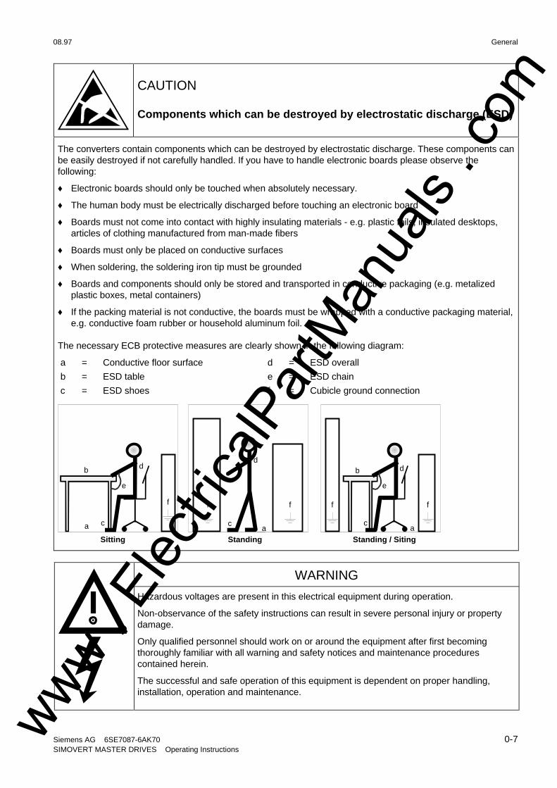
The necessary ECB protective measures are clearly shown in the following diagram:
a = Conductive floor surface d = ESD overall
b = ESD table e = ESD chain
c = ESD shoes f = Cubicle ground connection
StandingSitting Standing / Siting
a
b
e
d
c
d
ac
db
ca
e
ff f f f
WARNING
Hazardous voltages are present in this electrical equipment during operation.
Non-observance of the safety instructions can result in severe personal injury or propertydamage.
Only qualified personnel should work on or around the equipment after first becomingthoroughly familiar with all warning and safety notices and maintenance procedurescontained herein.
The successful and safe operation of this equipment is dependent on proper handling,installation, operation and maintenance.
www . El
ectric
alPar
tMan
uals
. com
General 08.97
0-8 Siemens AG 6SE7087-6AK70SIMOVERT MASTER DRIVES Operating Instructions
0.1 Safety and operating instructions for drive converters
Safety and operating instructionsfor drive converters
(in conformity with the low-voltage directive 73/23/EEC)
1. General
In operation, drive converters, depending on their degree of protection, may have live, uninsulated, andpossibly also moving or rotating parts, as well as hot surfaces.
In case of inadmissible removal of the required covers, of improper use, wrong installation or maloperation,there is the danger of serious personal injury and damage to property.
For further information, see documentation.
All operations serving transport, installation and commissioning as well as maintenance are to be carried outby skilled technical personnel (Observe IEC 364 or CENELEC HD 384 or DIN VDE 0100 and IEC 664 orDIN/VDE 0110 and national accident prevention rules!).
For the purposes of these basic safety instructions, "skilled technical personnel" means persons who arefamiliar with the installation, mounting, commissioning and operation of the product and have the qualificationsneeded for the performance of their functions.
2. Intended use
Drive converters are components designed for inclusion in electrical installations or machinery.
In case of installation in machinery, commissioning of the drive converter (i.e. the starting of normal operation)is prohibited until the machinery has been proved to conform to the provisions of the directive 89/392/EEC(Machinery Safety Directive - MSD). Account is to be taken of EN 60204.
Commissioning (i.e. the starting of normal opertion) is admissible only where conformity with the EMC directive(89/336/EEC) has been established.
The drive converters meet the requirements of the low-voltage directive 73/23/EEC. They are subject to theharmonized standards of the series prEN 50178/DIN VDE 0160 in conjunction with EN 60439-1/ VDE 0660,part 500, and EN 60146/ VDE 0558.
The technical data as well as information concerning the supply conditions shall be taken from the rating plateand from the documentation and shall be strictly observed.
3. Transport, storage
The instructions for transport, storage and proper use shall be complied with.
The climatic conditions shall be in conformity with prEN 50178.
4. Installation
The installation and cooling of the appliances shall be in accordance with the specifications in the pertinentdocumentation.
The drive converters shall be protected against excessive strains. In particular, no components must be bentor isolating distances altered in the course of transportation or handling. No contact shall be made withelectronic components and contacts.
Drive converters contain electrostatic sensitive components which are liable to damage through improper use.Electric components must not be mechanically damaged or destroyed (potential health risks).www .
Elec
tricalP
artM
anua
ls . c
om

08.97 General
Siemens AG 6SE7087-6AK70 0-9SIMOVERT MASTER DRIVES Operating Instructions
5. Electrical connection
When working on live drive converters, the applicable national accident prevention rules (e.g. VBG 4) must becomplied with.
The electrical installation shall be carried out in accordance with the relevant requirements (e.g. cross-sectionalareas of conductors, fusing, PE connection). For further information, see documentation.
Instructions for the installation in accordance with EMC requirements, like screening, earthing, location of filtersand wiring, are contained in the drive converter documentation. They must always be complied with, also fordrive converters bearing a CE marking. Observance of the limit values required by EMC law is theresponsibility of the manufacturer of the installation or machine.
6. Operation
Installations which include drive converters shall be equipped with additional control and protective devices inaccordance with the relevant applicable safety requirements, e.g. Act respecting technical equipment, accidentprevention rules etc. Changes to the drive converters by means of the operating software are admissible.
After disconnection of the drive converter from the voltage supply, live appliance parts and power terminalsmust not be touched immediately because of possibly energized capacitors. In this respect, the correspondingsigns and markings on the drive converter must be respected.
During operation, all covers and doors shall be kept closed.
7. Maintenance and servicing
The manufacturer’s documentation shall be followed.
Keep safety instructions in a safe place!
www . El
ectric
alPar
tMan
uals
. com

www . El
ectric
alPar
tMan
uals
. com

08.97 Description
Siemens AG 6SE7087-6AK70 1-1SIMOVERT MASTER DRIVES Operating Instructions
1 Description
SIMOVERT MASTER DRIVES are power electronic units. They are available as
♦ Compact units with three-phase- or DC current inputOutput range: 2.2 kW to 37 kW
♦ Chassis units with three-phase- or DC current inputOutput range: AC-AC: 45 kW to 400 kW
DC-AC: 45 kW to 1500 kW
♦ Cabinet units with three-phase- or DC current inputOutput range: 45 kW to 6.4 MW
The following control classes are available depending on the application conditions
♦ Vector control VC High demands on dynamic performance and accuracy
♦ Servo Control SC Servodrives
1.1 Applications
Drive converter with three-phase current input
The drive converter generates a variable-frequency three-phase system at the motor side from a fixed-frequencythree-phase supply (50/60 Hz). This variable-frequency three-phase system is used to continuously control thespeed of three-phase motors.
In the basic design, SIMOVERT MASTER DRIVES can be used for two-quadrant operation. Four-quadrantoperation is possible using the braking unit option. SIMOVERT MASTER DRIVES are suitable for single-motor-and multi-motor drives.
Technological functions and expansions can be realized via defined interfaces in the open-loop control section.
1.2 Mode of operation
The three-phase AC voltage, fed to the SIMOVERT MASTER DRIVES through the input terminals, is rectified ina B6 bridge rectifier and fed to the DC link through series resistors. The DC link is charged through two resistors,so that complete ground-fault proof operation is provided on the load side.
The converter is then ready for operation.
The inverter, configured using IGBT modules, generates a three-phase system from the DC link voltage to feedthe motor.
www . El
ectric
alPar
tMan
uals
. com

Description 08.97
1-2 Siemens AG 6SE7087-6AK70SIMOVERT MASTER DRIVES Operating Instructions
SIMOVERT VC
The inverter open-loop control uses a microprocessor and field-oriented vector control with an extremely fastclosed-loop current control. The drive can be precisely adapted to the demanded load torque as a result of thefield-oriented control, which in turn means that the drive has an extremely high dynamic performance.The pulsefrequency is preset to 2.5 kHz when the unit is shipped.
SIMOVERT VC is suitable for:
♦ Induction motors in both single-motor or multi-motor drives.For multi-motor drives, the motors within the group must be the same.
Some of the applications are, for example:
♦ Winder drives
♦ Rolling mill drives.
When the drive is shipped, closed-loop V/f control is preset. Closed-loop frequency control with field-orientedvector control must be parameterized.
The converter can be set, as a result of the precise motor simulation up to a maximum frequency of 300 Hz, withand without stall protection and with and without tachometer feedback.
SIMOVERT SC
The inverter open-loop control uses a microprocessor with field-oriented vector control, with a very fastsecondary closed-loop current control. High drive dynamic performance is achieved as a result of the fieldoriented vector control. When the unit is shipped, the pulse frequency is preset to 5 kHz.
SIMOVERT SC is suitable for:
♦ Single-motor drives with induction motors
Some of the applications are, for example
♦ Winder drives,
♦ Foil machines,
♦ Packaging machines
After power-up, only the motor must be selected and the drive can then be enabled. The drive can be matched tothe load moment of inertia and optimized by changing a closed-loop control parameter.
The converter operates with motor identification (MOTID). The maximum stator frequency is 400 Hz.The following operating modes can be selected:
♦ Closed-loop speed control
♦ Closed-loop torque control
The following encoders can be used:
♦ ERN 1387 encoders
♦ Encoders which are compatible to ERN 1387
♦ Resolvers
www . El
ectric
alPar
tMan
uals
. com

08.97 Description
Siemens AG 6SE7087-6AK70 1-3SIMOVERT MASTER DRIVES Operating Instructions
1.3 Operator control- and open-loop control possibilities
The unit can be controlled via
♦ the parameterization unit (PMU)
♦ an optional operator control panel (OP1)
♦ terminal strip
♦ a serial interface.
When networked with automation systems, the unit open-loop control is realized via optional interfaces andtechnology boards.
1.4 Block diagram
Motor-connection
U2/T1
V2/T2
W2/T3
PE2
Supply-connection
CU P
Connector for OP1(serial interface)
Terminal stripOption boards-in the elec-tronics box
DC link -connection
C / L+
D / L -
U1/L1
V1/L2
W1/L3
PE1
PMU
Fig. 1.1 Block diagram
www . El
ectric
alPar
tMan
uals
. com

www . El
ectric
alPar
tMan
uals
. com
08.97 Transport, Unpacking, Installation
Siemens AG 6SE7087-6AK70 2-1SIMOVERT MASTER DRIVES Operating Instructions
2 Transport, Unpacking, Installation
2.1 Transport and unpacking
The units are packed in the manufacturing plant corresponding to that specified when ordered. A product packinglabel is located on the outside of the packing.
Please observe the instructions on the packaging for transport, storage and professional handling.
For transportation with a fork-lift truck the converter is mounted on a wooden pallet.
Vibration and jolts must be avoided during transport, e.g. when setting the unit down.
The converter can be installed after it has been unpacked and checked to ensure that everything is completeand that the converter is not damaged.
If the converter is damaged you must inform your shipping company immediately.
The packaging consists of a wooden floor sectionand a PE foil to protect the equipment from humidity.It can be disposed of in accordance with local regulations.
Chassis units are supplied, as standard, with degree of protection IP00.
2.2 Storage
The converters must be stored in clean dry rooms.Temperatures between − 25 °C (−13 °F) and + 70 °C (158 °F)are permissible. Temperature fluctuations > 20 K per hour are not permissible.
WARNINGThe equipment should not be stored for longer than one year. If it is stored for longerperiods of time, the converter DC link capacitors must be formed at start-up.
Capacitor forming is described in Part 2 of the Operating Instructions.
www . El
ectric
alPar
tMan
uals
. com
Transport, Unpacking, Installation 08.97
2-2 Siemens AG 6SE7087-6AK70SIMOVERT MASTER DRIVES Operating Instructions
2.3 Mounting
The following are required for mounting:
♦ M8 bolt(s)
♦ Dimension drawing: Fehler! Verweisquelle konnte nicht gefunden werden. for type of construction K
WARNINGSafe converter operation requires that the equipment is mounted and commissioned byqualified personnel taking into account the warning information provided in this InstructionManual.
The general and domestic installation and safety regulations for work on electrical powerequipment (e.g. VDE) must be observed as well as the professional handling of tools andthe use of personnal protective equipment.
Death, severe bodily injury or significant material damage could result if these instructionsare not followed.
Chassis units do not provide any protection against direct contact. It is the usersresponsibility to ensure and provide the correct protection against contact according to therelevant accident prevention regulations VBG4, by appropriately designing the enclosure orenclosures around the chassis unit.
Remove shipping brace (marked).
Requirements at the point of installation:
The local guidelines and regulations must be observed when mounting and installing the equipment.
The unit is mounted corresponding to the dimension drawing in Section 2.4.
Equipment rooms must be dry and dust-free, moisture condensation is not permissible.
Ambient and cooling air must not contain any electrically conductive gases, vapors and dusts which coulddiminish the functionality. Dust-laden air must be filtered.
WARNING
When mounting in cabinets, a clearance of above and below must be provided so that thecooling air flow is not restricted (refer to dimension drawings, Section 2.4).
Dimension the cabinet cooling in line with the power loss and cooling air flow! (+ Section„Technical data“)
The converter ambient climate in operating rooms may not exceed the values of code F according to DIN 40040.For temperatures > 40 °C (104 °F) and installation altitudes > 1000 m, de-rating is required (+ Section„Technical data“).
www . El
ectric
alPar
tMan
uals
. com
08.97 Transport, Unpacking, Installation
Siemens AG 6SE7087-6AK70 2-3SIMOVERT MASTER DRIVES Operating Instructions
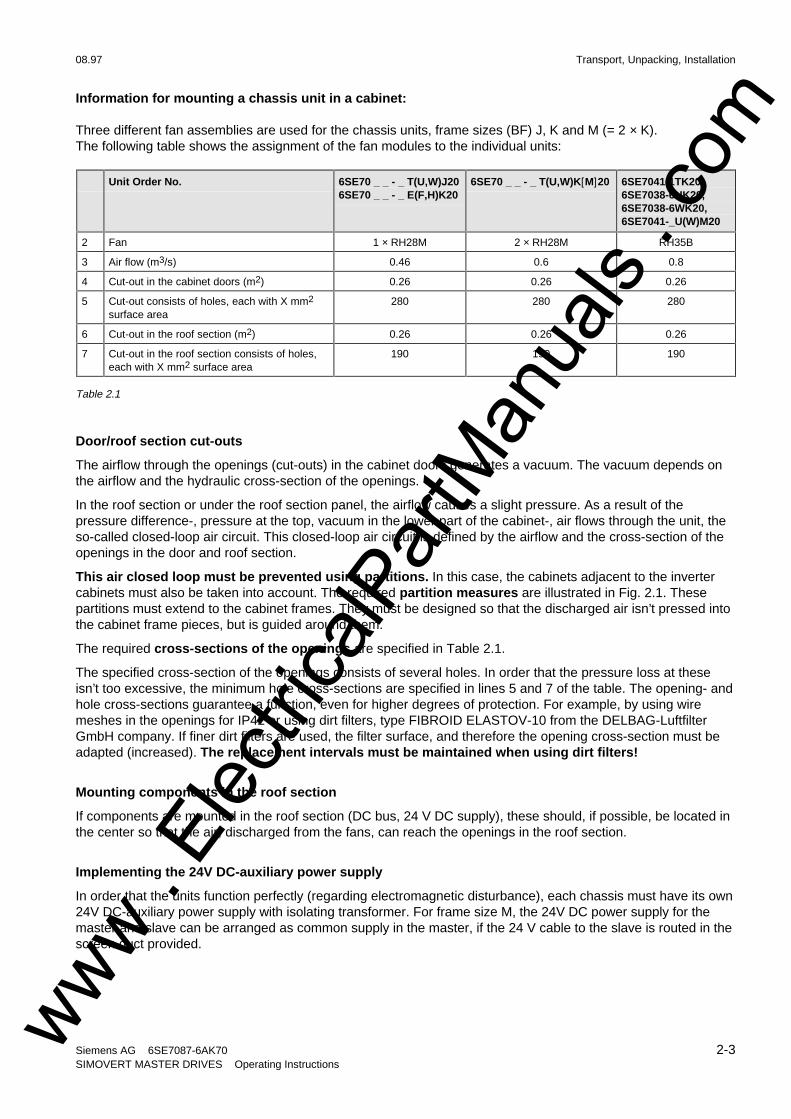
Information for mounting a chassis unit in a cabinet:
Three different fan assemblies are used for the chassis units, frame sizes (BF) J, K and M (= 2 × K).The following table shows the assignment of the fan modules to the individual units:
Unit Order No. 6SE70 _ _ - _ T(U,W)J206SE70 _ _ - _ E(F,H)K20
6SE70 _ _ - _ T(U,W)K[M]20 6SE7041-1TK20,6SE7038-6UK20,6SE7038-6WK20,6SE7041-_U(W)M20
2 Fan 1 × RH28M 2 × RH28M RH35B
3 Air flow (m3/s) 0.46 0.6 0.8
4 Cut-out in the cabinet doors (m2) 0.26 0.26 0.26
5 Cut-out consists of holes, each with X mm2
surface area280 280 280
6 Cut-out in the roof section (m2) 0.26 0.26 0.26
7 Cut-out in the roof section consists of holes,each with X mm2 surface area
190 190 190
Table 2.1
Door/roof section cut-outs
The airflow through the openings (cut-outs) in the cabinet doors generates a vacuum. The vacuum depends onthe airflow and the hydraulic cross-section of the openings.
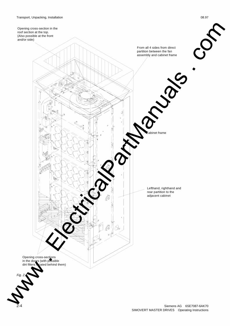
In the roof section or under the roof section panel, the airflow causes a slight pressure. As a result of thepressure difference-, pressure at the top, vacuum in the lower part of the cabinet-, air flows through the unit, theso-called closed-loop air circuit. This closed-loop air circuit is defined by the airflow and the cross-section of theopenings in the door and roof section.
This air closed loop must be prevented using partitions. In this case, the cabinets adjacent to the invertercabinets must also be taken into account. The required partition measures are illustrated in Fig. 2.1. Thesepartitions must extend to the cabinet frames. They must be designed so that the discharged air isn’t pressed intothe cabinet frame pieces, but is guided around them.
The required cross-sections of the openings are specified in Table 2.1.
The specified cross-section of the openings consists of several holes. In order that the pressure loss at theseisn’t too excessive, the minimum hole cross-sections are specified in lines 5 and 7 of the table. The opening- andhole cross-sections guarantee a function, even for higher degrees of protection. For example, by using wiremeshes in the openings for IP42 or using dirt filters, type FIBROID ELASTOV-10 from the DELBAG-LuftfilterGmbH company. If finer dirt filters are used, the filter surface, and therefore the opening cross-section must beadapted (increased). The replacement intervals must be maintained when using dirt filters!
Mounting components in the roof section
If components are mounted in the roof section (DC bus, 24 V DC supply), these should, if possible, be located inthe center so that the air, discharged from the fans, can reach the openings in the roof section.
Implementing the 24V DC-auxiliary power supply
In order that the units function perfectly (regarding electromagnetic disturbance), each chassis must have its own24V DC-auxiliary power supply with isolating transformer. For frame size M, the 24V DC power supply for themaster and slave can be arranged as common supply in the master, if the 24 V cable to the slave is routed in thescreen duct provided.
www . El
ectric
alPar
tMan
uals
. com
Transport, Unpacking, Installation 08.97
2-4 Siemens AG 6SE7087-6AK70SIMOVERT MASTER DRIVES Operating Instructions
From all 4 sides from directpartition between the fanassembly and cabinet frame
Cabinet frame
Lefthand, righthand and rear partition to the adjacent cabinet
Opening cross-sectionsin the doors (with possibledirt filters located behind them)
Opening cross-section in theroof section at the top.(Also possible at the front and/or side)
Fig. 2.1
www . El
ectric
alPar
tMan
uals
. com
08.97 Transport, Unpacking, Installation
Siemens AG 6SE7087-6AK70 2-5SIMOVERT MASTER DRIVES Operating Instructions
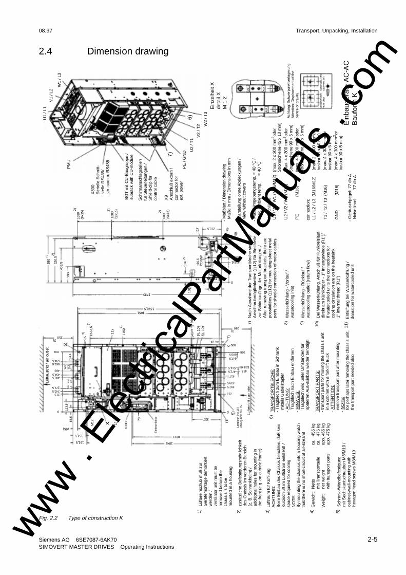
2.4 Dimension drawing
C/L
+D
/L-
AU
XA
UX
Ein
baug
erät
e A
C-A
CB
aufo
rm K
3) 4)G
ewic
ht:
1) 2)
Net
tom
it T
rans
port
teile
net w
eigh
tw
ith tr
ansp
ort p
arts
Wei
ght:
ca.
455
kg
ca.
475
kg
app.
455
kg
app.
475
kg
5)S
chra
nk-/
Wan
dbef
estig
ung
mit
Sec
hska
ntsc
hrau
ben
M8/
M10
/ca
bine
t-/w
all-m
ount
ing
with
hexa
gon
head
scr
ews
M8/
M10
6)T
RA
NS
PO
RT
BLE
CH
E:
- T
ragb
lech
zum
Ein
bau
in S
chra
nk m
ittel
s G
abel
stap
ler
- A
CH
TU
NG
: T
ragb
lech
nac
h E
inba
u en
tfern
en-
HIN
WE
IS:
Tra
gble
ch w
ird u
nter
Um
stän
den
für
spä
tere
n A
us-/
Ein
bau
wie
der
benö
tigt!
TR
AN
SP
OR
T P
AR
TS
:-
tran
spor
t par
ts fo
r m
ovin
g th
e ch
assi
s un
it i
n a
cabi
net w
ith a
fork
lift
truc
k-
AT
TE
NT
ION
: r
emov
e tr
ansp
ort p
art a
fter
mou
ntin
g-
NO
TE
: f
or p
erha
ps la
ter
rem
ovin
g th
e ch
assi
s un
it, t
he tr
ansp
ort p
art n
eede
d al
so
U1
/ L1
V1
/ L2
W1
/ L3
PM
U
BG
T m
it C
U-B
augr
uppe
/su
brac
k w
ith C
U-m
odul
e
Sch
irman
schl
agst
elle
nfü
r S
teue
rleitu
ngen
/S
hiel
d-cl
ip fo
rco
ntro
l cab
le
X9
Ans
chlu
ß e
xter
n /
conn
ecto
r fo
rex
t. po
wer
PE
/ G
ND U
2 / T
1
V2
/ T2 W
2 / T
3
U1
/ V1
/ W1
(M16
/M12
)2
(max
. 2 x
300
mm
ode
rS
trom
schi
ene
45 x
10
mm
)
U2
/ V2
/ W2
(M16
)(m
ax. 4
x 3
00 m
m o
der
Str
omsc
hien
e 90
x 5
mm
)
2
PE
(M
16)
(max
. 4 x
300
mm
ode
rS
trom
schi
ene
90 x
5 m
m)
2 2(m
ax. 2
x 3
00 m
m o
rbu
sbar
45
x 10
mm
)(m
ax. 4
x 3
00 m
m o
rbu
sbar
90
x 5
mm
)2
conn
ectio
n:
- G
eräu
schp
egel
: 77
db A
Noi
se le
vel:
77 d
b A
7)
6)
Luftr
aum
für
Küh
lung
AC
HT
UN
G:
Bei
m E
inba
u de
s C
hass
is b
each
ten,
daß
kei
nK
urzs
chlu
ß im
Luf
tstr
om e
ntst
eht!
/sp
ace
requ
ired
for
cool
ing
NO
TE
:B
y m
ount
ing
the
chas
sis
into
a h
ousi
ng w
atch
that
ther
e is
no
shor
t-ci
rcui
t of a
ir-st
ream
!
Lüfte
rein
schu
b m
uß z
urG
erät
emon
tage
dem
ontie
rtw
erde
n /
vent
ilato
r un
it m
ust b
ere
mov
ed b
efor
e th
ech
assi
s is
to b
em
ount
ed in
a h
ousi
ng
zusä
tzlic
he B
efes
tigun
gsm
öglic
hkei
tde
s C
hass
is im
vor
dere
n B
erei
ch(z
. B. S
chra
nkho
lm)
/ ad
ditio
nal h
oles
for
mou
ntin
g in
the
fron
t (e.
g. o
n cu
bicl
e fra
me)
X30
0S
erie
lle S
chni
tt-st
elle
RS
485/
ser.
com
m. R
S48
5
Ein
zelh
eit X
deta
il X
M 1
:2
Ach
tung
: Sch
wer
punk
tver
lage
rung
Atte
ntio
n: D
ispl
acem
ent o
f the
cent
re o
f gra
vity
Vor
dera
nsic
htF
ront
vie
wS
eite
nan
s. li
nks
side
vie
w le
ft
- M
aßbl
att /
Dim
ensi
on d
raw
ing
Maß
e in
mm
/ D
imen
sion
s in
mm
- D
arst
ellu
ng o
hne
Abd
ecku
ngen
/ v
iew
with
out c
over
s
- M
ax. U
mge
bung
stem
p. =
40
°C /
max
. am
bien
t tem
p.
=
40
°C
- A
nsch
lüss
e:
L1 /
L2 /
L3 (
M16
/M12
)
T1
/ T2
/ T3
(M
16)
GN
D
(
M16
)(m
ax. 4
x 3
00 m
m o
rbu
sbar
90
x 5
mm
)2
7)N
ach
Abn
ahm
e de
r T
rans
port
blec
he s
ind
hier
Ans
chra
ubm
öglic
hkei
ten
( ∅12
) für
Ble
chte
ilezu
r S
chirm
aufla
ge d
er M
otor
leitu
ngen
. /A
fter
rem
ovin
g tr
ansp
ort b
rack
ets,
ther
e ar
epo
ssib
ilitie
s ( ∅
12)
for
mou
ntin
g sh
eet m
etal
part
s fo
r sh
eeld
con
nect
ion
of m
otor
cab
les.
8)W
asse
rküh
lung
- V
orla
uf /
wat
erco
olin
g in
let
9)W
asse
rküh
lung
- R
ückl
auf /
wat
erco
olin
g ou
tlet (
retu
rn fl
ow)
10)
Bei
Was
serk
ühlu
ng, A
nsch
luß
für
Küh
lkre
isla
ufdi
rekt
am
Küh
lkör
per
- 1"
Inne
ngew
inde
(R
1")/
If w
ater
cool
ed u
nits
the
conn
ectio
ns fo
rco
olin
g ci
rcul
atio
n ar
e on
the
heat
sink
1" in
tern
al th
read
(R
1")
11)
Lufte
intr
itt /
air
inle
t
Ent
lüftu
ng b
ei W
asse
rküh
lung
/de
arat
ion
for
wat
erco
oled
uni
t
Lufta
ustr
itt /
air
outle
t
Lan
gloc
h 9
x 15
/ob
long
hol
e 9
x 15
1)
5)
7)7)
2)
10)
9), 1
0)
8), 1
0)
1043
Ele
ktro
nik
box
2)
2)
1033
337
161,5
151,5
(55)
0
213243,5274,5
403,5434,5483
563,5594,5
708
350
1678,51651
350
800+5
708689,5647,5
514,5472,5
528±5483
0
417±5
339,5297,5
213
M12 X
X30
0
7053,5
123,
5U
1/L1
V1/
L2
W1/
L3 ∅17
∅13,
5
5)
9,5
2) 1533
,52)
11)
1150
340
±535
02)
24
1730
222,5
235,5
295,5
145,5
550
520,
5
408,
5
190
1680
(9x1
5)2)
1280
(9x1
5)2)
680
(9x1
5)
∅17 45
50
0
104
±5
∅16,
5P
E/G
ND
3)
3)
PE
/GN
D
+5
U2/
T1
V2/
T2W
2/T3
Fig. 2.2 Type of construction Kwww . El
ectric
alPar
tMan
uals
. com
www . El
ectric
alPar
tMan
uals
. com
08.97 Connecting-up
Siemens AG 6SE7087-6AK70 3-1SIMOVERT MASTER DRIVES Operating Instructions
3 Connecting-up
WARNINGSIMOVERT MASTER DRIVES are operated at high voltages.
The equipment must be in a no-voltage condition (disconnected from the supply) before anywork is carried-out!
Only professionally trained, qualified personnel must work on or with the unit.
Death, severe bodily injury or significant material damage could occur if these warninginstructions are not observed.
Extreme caution should be taken when working-on the unit when it is open, as externalpower supplies may be connected. The power terminals and control terminals can still be athazardous potentials even when the motor is stationary.
Hazardous voltages are still present in the unit up to 5 minutes after it has been powered-down due to the DC link capacitors. Thus, the appropriate delay time must be observedbefore opening-up the unit.
Forming the DC link capacitors:
The storage time should not exceed one year. The converter DC link capacitors must beformed at start-up if the unit has been stored for a longer period of time.
Forming is described in the Instruction Manual, Part 2.
The user is responsible, that the motor, converter and any other associated devices or unitsare installed and connected-up according to all of the recognized regulations in thatparticular country as well as other regionally valid regulations. Cable dimensioning, fusing,grounding, shutdown, isolation and overcurrent protection should be especially observed.
If a protective device trips in a current arm, then a fault current could have been interrupted.In order to reduce the danger of fire or electric shock, the live parts and over components ofthe converter should be checked and damaged components replaced.
INFORMATION
♦ Protection: Fuses must be incorporated in the equipment supply connection. For a list of therecommended fuses, refer to Table 3.1.
♦ Supply rating: The converter is suitable for connecting to supplies with a short-circuit rating (supply)≤ 100 × rated output (converter).
♦ The converter should be connected via a line reactor according to Table 3.1.
♦ Cabling/wiring: Connecting cables should be dimensioned according to the local regulations and accordingto section „Power connections“. The insulation should be suitable for 75°C.
www . El
ectric
alPar
tMan
uals
. com
Connecting-up 08.97
3-2 Siemens AG 6SE7087-6AK70SIMOVERT MASTER DRIVES Operating Instructions
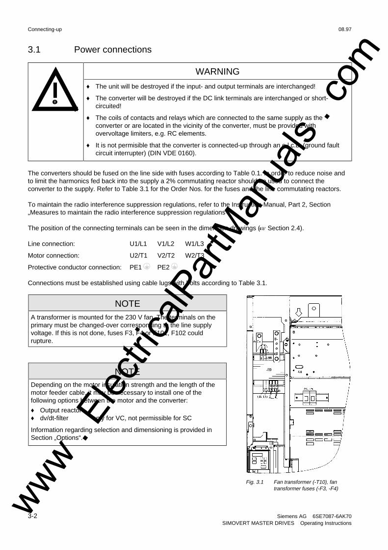
3.1 Power connections
WARNING
♦ The unit will be destroyed if the input- and output terminals are interchanged!
♦ The converter will be destroyed if the DC link terminals are interchanged or short-circuited!
♦ The coils of contacts and relays which are connected to the same supply as theconverter or are located in the vicinity of the converter, must be provided withovervoltage limiters, e.g. RC elements.
♦ It is not permisible that the converter is connected-up through an e.l.c.b. (ground faultcircuit interrupter) (DIN VDE 0160).
The converters should be fused on the line side with fuses according to Table 0.1. In order to reduce noise andto limit the harmonics fed back into the supply a 2% commutating reactor should be used to connect theconverter to the supply. Refer to Table 3.1 for the Order Nos. for the fuses and the line commutating reactors.
To maintain the radio interference suppression regulations, refer to the Instruction Manual, Part 2, Section„Measures to maintain the radio interference suppression regulations“.
The position of the connecting terminals can be seen in the dimension drawings (+ Section 2.4).
Line connection: U1/L1 V1/L2 W1/L3
Motor connection: U2/T1 V2/T2 W2/T3
Protective conductor connection: PE1 PE2
Connections must be established using cable lugs with bolts according to Table 3.1.
NOTEA transformer is mounted for the 230 V fan. The terminals on theprimary must be changed-over corresponding to the line supplyvoltage. If this is not done, fuses F3, F4 or F101, F102 couldrupture.
NOTEDepending on the motor insulation strength and the length of themotor feeder cable, it may be necessary to install one of thefollowing options between the motor and the converter:
♦ Output reactor♦ dv/dt-filter only for VC, not permissible for SC
Information regarding selection and dimensioning is provided inSection „Options“.
Fig. 3.1 Fan transformer (-T10), fantransformer fuses (-F3, -F4)
www . El
ectric
alPar
tMan
uals
. com
08.97 Connecting-up
Siemens AG 6SE7087-6AK70 3-3SIMOVERT MASTER DRIVES Operating Instructions
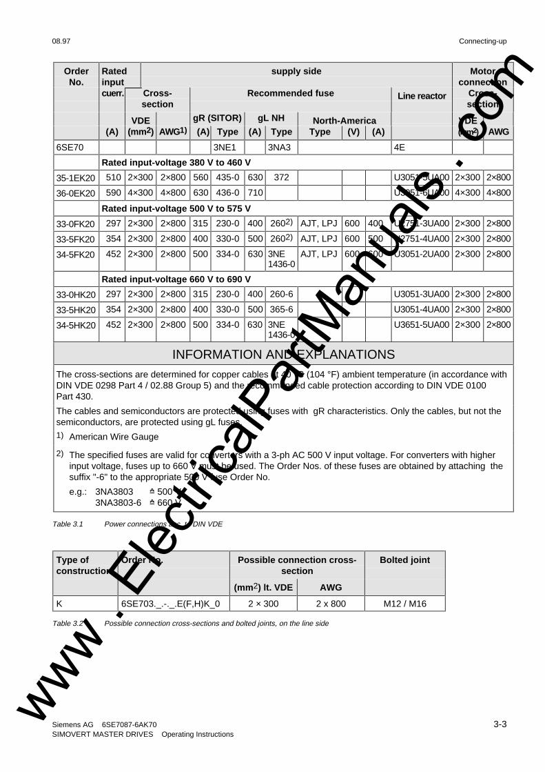
OrderNo.
Ratedinput
supply side Motorconnection
cuerr. Cross-section
Recommended fuse Line reactor Cross-section
VDE gR (SITOR) gL NH North-America VDE(A) (mm2) AWG1) (A) Type (A) Type Type (V) (A) (mm2) AWG
6SE70 3NE1 3NA3 4E
Rated input-voltage 380 V to 460 V
35-1EK20 510 2×300 2×800 560 435-0 630 372 U3051-5UA00 2×300 2×800
36-0EK20 590 4×300 4×800 630 436-0 710 U3051-6UA00 4×300 4×800
Rated input-voltage 500 V to 575 V
33-0FK20 297 2×300 2×800 315 230-0 400 2602) AJT, LPJ 600 400 U2751-3UA00 2×300 2×800
33-5FK20 354 2×300 2×800 400 330-0 500 2602) AJT, LPJ 600 500 U2751-4UA00 2×300 2×800
34-5FK20 452 2×300 2×800 500 334-0 630 3NE1436-0
AJT, LPJ 600 600 U3051-2UA00 2×300 2×800
Rated input-voltage 660 V to 690 V
33-0HK20 297 2×300 2×800 315 230-0 400 260-6 U3051-3UA00 2×300 2×800
33-5HK20 354 2×300 2×800 400 330-0 500 365-6 U3051-4UA00 2×300 2×800
34-5HK20 452 2×300 2×800 500 334-0 630 3NE1436-0
U3651-5UA00 2×300 2×800
INFORMATION AND EXPLANATIONS
The cross-sections are determined for copper cables at 40 °C (104 °F) ambient temperature (in accordance withDIN VDE 0298 Part 4 / 02.88 Group 5) and the recommended cable protection according to DIN VDE 0100Part 430.
The cables and semiconductors are protected using fuses with gR characteristics. Only the cables, but not thesemiconductors, are protected using gL fuses.1) American Wire Gauge
2) The specified fuses are valid for converters with a 3-ph AC 500 V input voltage. For converters with higherinput voltage, fuses up to 660 V must be used. The Order Nos. of these fuses are obtained by attaching thesuffix "-6" to the appropriate 500 V fuse Order No.
e.g.: 3NA3803 =̂ 500 V3NA3803-6 =̂ 660 V
Table 3.1 Power connections acc. to DIN VDE
Type ofconstruction
Order No. Possible connection cross-section
Bolted joint
(mm2) lt. VDE AWG
K 6SE703._.-._.E(F,H)K_0 2 × 300 2 x 800 M12 / M16
Table 3.2 Possible connection cross-sections and bolted joints, on the line side
www . El
ectric
alPar
tMan
uals
. com
Connecting-up 08.97
3-4 Siemens AG 6SE7087-6AK70SIMOVERT MASTER DRIVES Operating Instructions
3.1.1 Protective conductor connection
The protective conductor should be connected-up on both the supply- and motor sides. It should be dimensionedaccording to the power connections.
3.1.2 DC link connection
The "braking unit" (6SE7087-6CX87-2DA0) and "dv/dt filter" (6SE7087-6CX87-1FD0) options can be connectedat the DC link terminals C/L+ and D/L− (+ Fig. 5.5). They are not suitable for connecting other inverter units (e.g.DC drive converters).
This connection is not suitable for connecting a rectifier or rectifier/regenerative feedback unit.
Using option M65, it is possible to shift the DC link terminals C/L+ and D/L− towards the bottom.
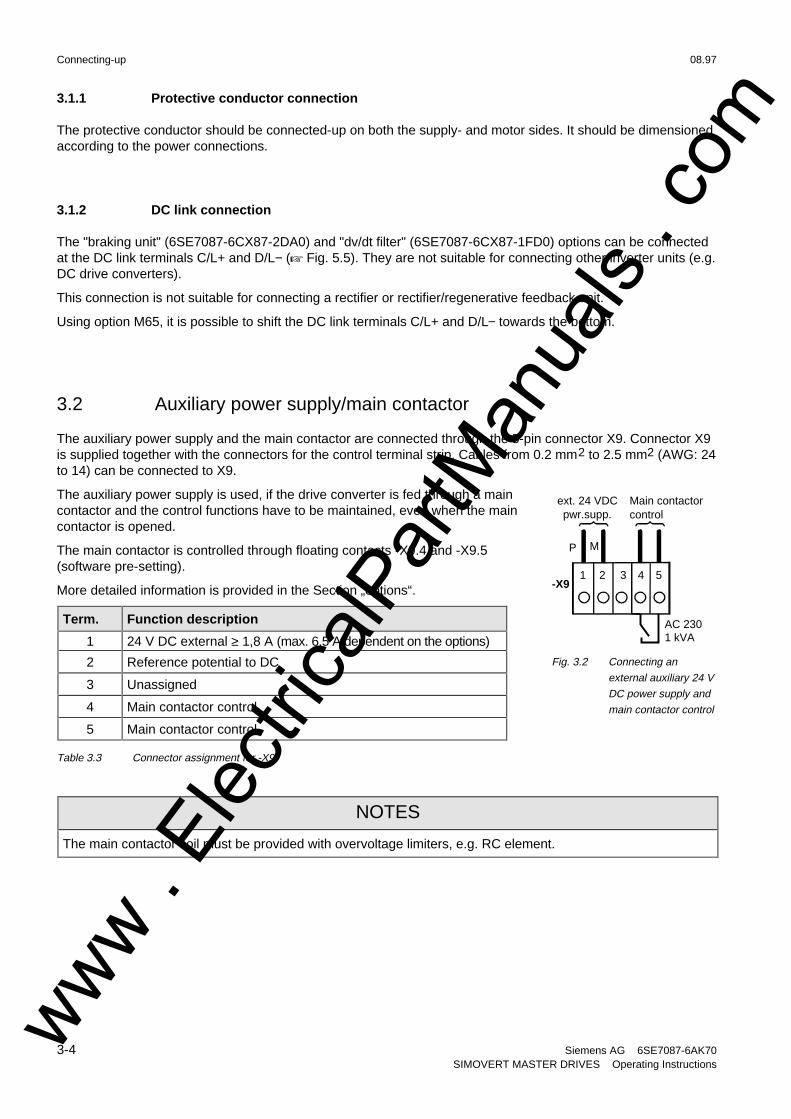
3.2 Auxiliary power supply/main contactor
The auxiliary power supply and the main contactor are connected through the 5-pin connector X9. Connector X9is supplied together with the connectors for the control terminal strip. Cables from 0.2 mm2 to 2.5 mm2 (AWG: 24to 14) can be connected to X9.
The auxiliary power supply is used, if the drive converter is fed through a maincontactor and the control functions have to be maintained, even when the maincontactor is opened.
The main contactor is controlled through floating contacts -X9.4 and -X9.5(software pre-setting).
More detailed information is provided in the Section „options“.
Term. Function description
1 24 V DC external ≥ 1,8 A (max. 6,5 A dependent on the options)
2 Reference potential to DC
3 Unassigned
4 Main contactor control
5 Main contactor control
Table 3.3 Connector assignment for -X9
NOTES
The main contactor coil must be provided with overvoltage limiters, e.g. RC element.
1 2 3 4 5-X9
P M
ext. 24 VDCpwr.supp.
AC 230 1 kVA
Main contactorcontrol
Fig. 3.2 Connecting an
external auxiliary 24 V
DC power supply and
main contactor control
www . El
ectric
alPar
tMan
uals
. com

08.97 Connecting-up
Siemens AG 6SE7087-6AK70 3-5SIMOVERT MASTER DRIVES Operating Instructions
3.3 Instructions for EMC-correct installation
EMC (Electromagnetic Compatibility) involves the noise emission and noise immunity of electrical equipment.
Optional radio interference suppression filters are available to limit the noise emission.
1U1
1V1
1W1
1U2
1V2
1W2
Radio interferencesuppression filter
Supply
Load
Supply
L1
L2
L3
PE
L1’
L2’
L3’
PE’
Line reactor SIMOVERTMASTER DRIVES
U1
V1
W1
PE1
Mounting panel
M3~
Screenedmotor cable
U2V2W2PE2
Fig. 3.3 Location of the components
The radio interference suppression filter and drive converter must beconnected through a large surface area. The most favorable method is tomount all of the components on a bare metal mounting panel (e.g.galvanized steel). A line reactor must be connected between the radiointerference suppression filter and the drive converter.
The cabling should be kept as short as possible. The line feeder cable tothe radio interference suppression filter should be routed separately awayfrom other cables.
The motor must be connected using a screened cable, e.g. SiemensPROTOFLEX-EMV-CY (cross-section up to 120 mm2) or SiemensPROTODUR NYCW (cross-section > 120 mm2). The screen must beconnected to the motor- and drive converter housing through the largestpossible surface area to keep inductances as low as possible.
Use screened control cables to increase the noise immunity. Connect thescreens of the control cables to the mounting positions provided. Screenclamps are provided with every SIMOVERT MASTER DRIVES to connectthe screens of the control cables (+ Fig. 3.4.1). Otherwise, cable ties canbe used to connect the screen (+ Fig. 3.4.2).
♦ Do not interrupt the screens, e.g. when installing intermediateterminals.
♦ Control cables and power cables (= line feeder cable, motor cable)must be routed separately away from one another.
You will find more detailed information in the brochure (Installationinstructions for EMC correct design of drives“(Order No.: 6SE7087-6CX87-8CE0).
Screenclamp
Fig. 3.4.1
Cable tie
Fig. 3.4.2
Fig. 3.4 Connecting the screens ofsignal cables for SIMOVERTMASTER DRIVESwww .
Elec
tricalP
artM
anua
ls . c
om

www . El
ectric
alPar
tMan
uals
. com
08.97 Operator control
Siemens AG 6SE7087-6AK70 4-1SIMOVERT MASTER DRIVES Operating Instructions
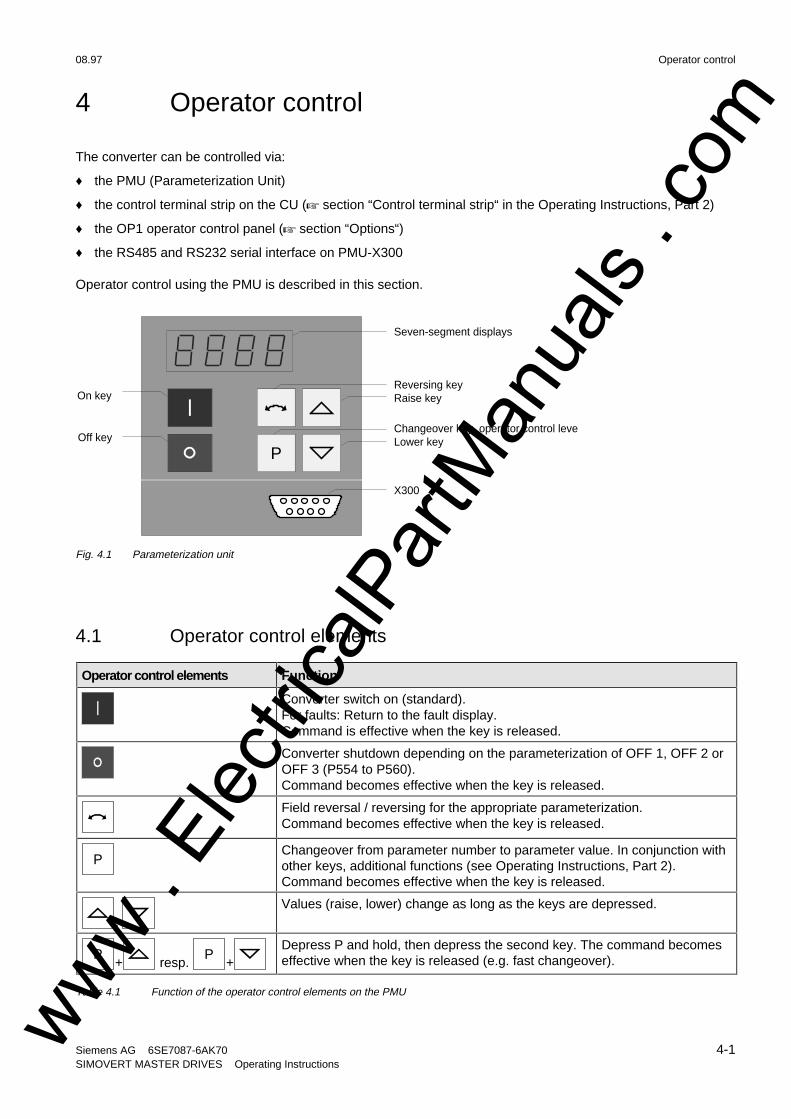
4 Operator control
The converter can be controlled via:
♦ the PMU (Parameterization Unit)
♦ the control terminal strip on the CU (+ section “Control terminal strip“ in the Operating Instructions, Part 2)
♦ the OP1 operator control panel (+ section “Options“)
♦ the RS485 and RS232 serial interface on PMU-X300
Operator control using the PMU is described in this section.
P
On key
Off key
Reversing keyRaise key
Changeover key, operator control leveLower key
Seven-segment displays
X300
Fig. 4.1 Parameterization unit
4.1 Operator control elements
Operator control elements Function
Converter switch on (standard).For faults: Return to the fault display.Command is effective when the key is released.
Converter shutdown depending on the parameterization of OFF 1, OFF 2 orOFF 3 (P554 to P560).Command becomes effective when the key is released.
Field reversal / reversing for the appropriate parameterization.Command becomes effective when the key is released.
PChangeover from parameter number to parameter value. In conjunction withother keys, additional functions (see Operating Instructions, Part 2).Command becomes effective when the key is released.
, Values (raise, lower) change as long as the keys are depressed.
P+ resp.
P+
Depress P and hold, then depress the second key. The command becomeseffective when the key is released (e.g. fast changeover).
Table 4.1 Function of the operator control elements on the PMU
www . El
ectric
alPar
tMan
uals
. com
Operator control 08.97
4-2 Siemens AG 6SE7087-6AK70SIMOVERT MASTER DRIVES Operating Instructions
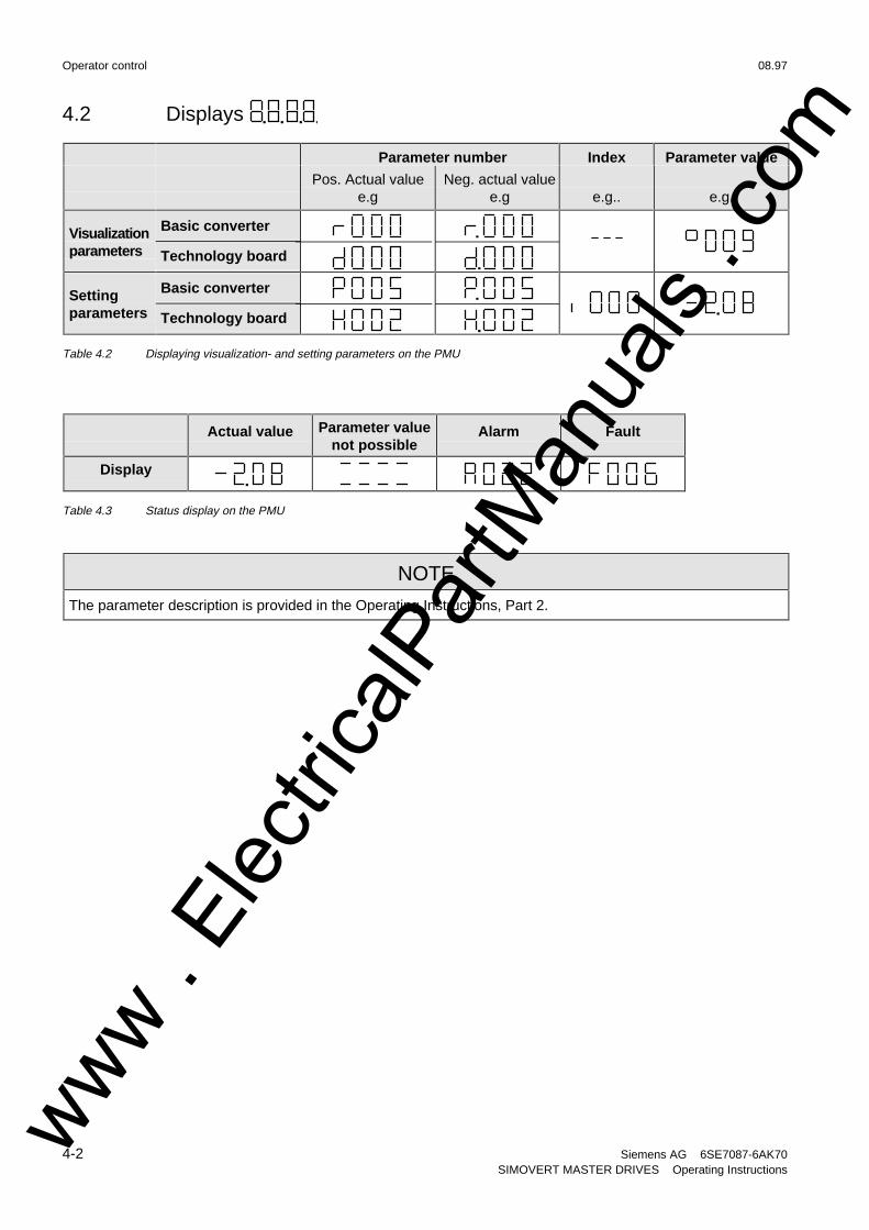
4.2 Displays
Parameter number Index Parameter value
Pos. Actual valuee.g
Neg. actual valuee.g e.g.. e.g.
Visualizationparameters
Basic converter
Technology board− − −
Settingparameters
Basic converter
Technology board
Table 4.2 Displaying visualization- and setting parameters on the PMU
Actual value Parameter valuenot possible
Alarm Fault
Display
Table 4.3 Status display on the PMU
NOTE
The parameter description is provided in the Operating Instructions, Part 2.
www . El
ectric
alPar
tMan
uals
. com
08.97 Maintenance
Siemens AG 6SE7087-6AK70 5-1SIMOVERT MASTER DRIVES Operating Instructions
5 Maintenance
WARNING
SIMOVERT MASTER DRIVES are operated at high voltages.
All work carried-out on or with the equipment must conform to all of the relevant nationalelectrical codes (VBG4 in Germany).
Maintenance and service work may only be executed by qualified personnel.
Only spare parts authorized by the manufacturer may be used.
The specified maintenance intervals and also the instructions for repair and replacementmust be adhered to.
The drive units have hazardous voltage levels up to 5 min after the converter has beenpowered-down due to the DC link capacitors so that the unit must only be opened after anappropriate delay time.
The power- and control terminals can still be at hazardous voltage levels even though themotor is at a standstill.
If it is absolutely necessary that the drive converter must be worked on when powered-up:♦ never touch any live components.
♦ only use the appropriate measuring and test equipment and protective clothing.
♦ always stand on an ungrounded, isolated and ESD-compatible pad.
If these warnings are not observed this can result in death, severe bodily injury or significantmaterial damage.
Always have your MASTER DRIVE converter Order No. and serial No. available when contacting the servicedepartment. These numbers and other important data are located on the drive converter rating plate.
5.1 Maintenance requirements
The fans are designed for a service life of 35000 hours at an ambient temperature of TU = 40 °C. They must bereplaced before their service life expires so that the drive converter availability is guaranteed.
www . El
ectric
alPar
tMan
uals
. com
Maintenance 08.97
5-2 Siemens AG 6SE7087-6AK70SIMOVERT MASTER DRIVES Operating Instructions
5.2 Replacing components
WARNING
The fan may only replaced by qualified personnel.
The drive converters are still at hazardous voltage levels up to 5 min. after theunit has been powered-down as a result of the DC link capacitors.If these warnings are not observed, death, severe bodily injury or considerablematerial damage could occur.
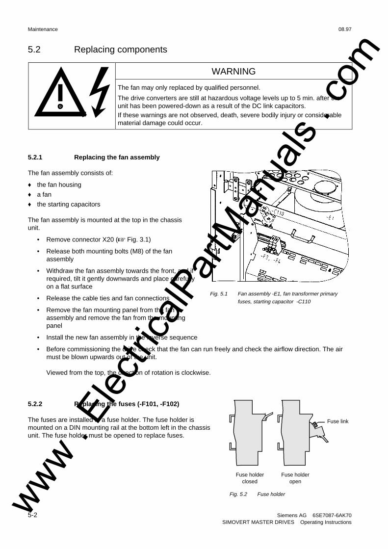
5.2.1 Replacing the fan assembly
The fan assembly consists of:
♦ the fan housing
♦ a fan
♦ the starting capacitors
The fan assembly is mounted at the top in the chassisunit.
• Remove connector X20 (+ Fig. 3.1)
• Release both mounting bolts (M8) of the fanassembly
• Withdraw the fan assembly towards the front, and ifrequired, tilt it gently downwards and place carefullyon a flat surface
• Release the cable ties and fan connections
• Remove the fan mounting panel from the fanassembly and remove the fan from the mountingpanel
• Install the new fan assembly in the inverse sequence
• Before commissioning the drive check that the fan can run freely and check the airflow direction. The airmust be blown upwards out of the unit.
Viewed from the top, the direction of rotation is clockwise.
5.2.2 Replacing the fuses (-F101, -F102)
The fuses are installed in a fuse holder. The fuse holder ismounted on a DIN mounting rail at the bottom left in the chassisunit. The fuse holder must be opened to replace fuses.
Fig. 5.1 Fan assembly -E1, fan transformer primary
fuses, starting capacitor -C110
Fuse link
Fuse holderclosed
Fuse holderopen
Fig. 5.2 Fuse holderwww . El
ectric
alPar
tMan
uals
. com
08.97 Maintenance
Siemens AG 6SE7087-6AK70 5-3SIMOVERT MASTER DRIVES Operating Instructions
5.2.3 Replacing the fan transformer fuses (-F3, -F4)
The fuses are located in fuse holders. These are located in front of the air deflection plate, below the fan.The fuse holder must be opened to replace the fuses (+ Fig. 3.1 / Fig. 5.1 / Fig. 5.2).
5.2.4 Replacing the fan transformer (-T10)
The fan transformer is mounted above the electronics box behind a protective cover (+ Fig. 3.1).
♦ Tag and remove the connecting cables at the transformer.
♦ Loosen the screws at the bottom at the transformer mounting panel, secure the transformer so that it cannotfall, and remove the transformer after having released all of the screws.
♦ Mount the new fan transformer in the inverse sequence.
5.2.5 Replacing the starting capacitor
The starting capacitor (-C110) is mounted within the fan housing (+ Fig. 5.1).
♦ Remove the plug connections from the starting capacitor.
♦ Unbolt the starting capacitor.
♦ Install a new starting capacitor in the inverse sequence (4,5 Nm).
5.2.6 Replacing the capacitor bank
The capacitor assembly consists of three boards. Each board has a capacitor mounting element and a DC linkbus connection.
• Remove the plug connections
• Release the mechanical retaining elements (three screws: two at the left, one at the right)
• Remove the capacitor by slightly raising them and withdrawing them from the drive converter towards thefront.
CAUTION
The capacitors weight up to 15 kg depending on the drive converter rating.
• Install a new capacitor bank in the inverse sequence.
5.2.7 Replacing SML and SMU
SML Snubber Module LowerSMU Snubber Module Upper
♦ Remove the capacitors
♦ Release the mounting screws (4 × M8 (torque: 8 - 10 Nm), 1 × M4 (max. 1.8 Nm))
♦ Remove the SML / SMU
Install the new board in the reverse sequence.
www . El
ectric
alPar
tMan
uals
. com
Maintenance 08.97
5-4 Siemens AG 6SE7087-6AK70SIMOVERT MASTER DRIVES Operating Instructions
5.2.8 Removing and installing the module busbars
♦ Removal
• remove the capacitors
• release the bolts holding the module busbarsBolts M8 power connections
M6 mounting and distance piecesM4 snubber circuitry
• remove the SMU / SML insulation
• lift out the module busbars
♦ Installation
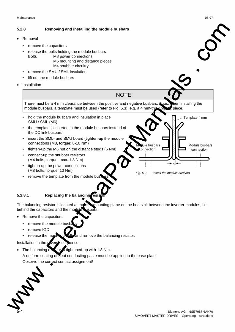
NOTE
There must be a 4 mm clearance between the positive and negative busbars. Thus, when installing themodule busbars, a template must be used (refer to Fig. 5.3), e.g. a 4 mm-thick plastic piece.
• hold the module busbars and insulation in placeSMU / SML (M6)
• the template is inserted in the module busbars instead ofthe DC link busbars
• insert the SML- and SMU board (tighten-up the moduleconnections (M8, torque: 8-10 Nm)
• tighten-up the M6 nut on the distance studs (6 Nm)
• connect-up the snubber resistors(M4 bolts, torque: max. 1.8 Nm)
• tighten-up the power connections(M8 bolts, torque: 13 Nm)
• remove the template from the module busbars.
5.2.8.1 Replacing the balancing resistor
The balancing resistor is located at the rear mounting plane on the heatsink between the inverter modules, i.e.behind the capacitors and the module busbars.
♦ Remove the capacitors
• remove the module busbars
• remove IGD
• release the mounting bolts and remove the balancing resistor.
Installation in the reverse sequence.
♦ The balancing resistor is tightened-up with 1.8 Nm.
A uniform coating of heat conducting paste must be applied to the base plate.
Observe the correct contact assignment!
Module busbars+ connection
Template 4 mm
4
Module busbars− connection
Fig. 5.3 Install the module busbars
www . El
ectric
alPar
tMan
uals
. com
08.97 Maintenance
Siemens AG 6SE7087-6AK70 5-5SIMOVERT MASTER DRIVES Operating Instructions
5.2.9 Replacing boards
WARNING
The boards may only be replaced by qualified personnel.
It is not permissible that the boards are withdrawn or inserted under voltage.Death, severe bodily injury or significant materal damage might result if theseinstructions are not observed.
CAUTION
Boards contain components which could be damaged by electrostatic discharge. Thehuman body must be discharged immediately before an electronics board is touched.This can be simply done by touching a conductive, grounded object immediately beforehand(e.g. bare metal cubicle components).
NOTE
When replacing the IVI board and (or) the IGD board, ensure that the fiber-optic cable is inserted up to its endstop!
5.2.9.1 Replacing the IVI
IVI Inverter-Value Interface
The IVI is bolted to the rear of the electronics box
♦ Remove the electronics module to the endstop
♦ Remove the ground connection at the electronics module
• Remove all of the boards from the electronics box and place them down on a suitable surface whichcannot be statically charged-up
• Remove both mounting bolts from the electronics box (Fig. 5.6)
• Release the electronics box and remove towards the front.
• Remove the ABO (Adaption Board)
• Release the fiber-optic cables
• Unbolt the IVI and remove
• Install the new IVI in the inverse sequence
www . El
ectric
alPar
tMan
uals
. com
Maintenance 08.97
5-6 Siemens AG 6SE7087-6AK70SIMOVERT MASTER DRIVES Operating Instructions
5.2.9.2 Replacing the VDU and VDU resistor
VDU Voltage-Dividing Unit
VDU and VDU resistor are only available for drive converters with higher supply voltages. The VDU mountingbracket is part of the electronic module assembly.
♦ VDU
• Remove the plug connectors
• Release the mounting bolt
• Remove the VDU
Install the new VDU in the inverse sequence.
♦ VDU resistor
• Release the cable ties
• Remove the plug connections
• Unbolt the VDU resistor
Install the new VDU resistor in the inverse sequence
5.2.9.3 Replacing the PSU
PSU Power-Supply Unit (Power Supply)
♦ Remove the VDU and VDU resistor (if available)
♦ Remove the VDU mounting panel
♦ Release the plug connections on the PSU
♦ Release the bolts ( six Torx M4) on the PSU
♦ Remove the PSU
Install the new PSU in the inverse sequence
5.2.9.4 Replacing the IGD
IGD IGBT-Gate Drive
The IGD is located behind the module busbars and consists of a board.
♦ Remove the capacitors
♦ Remove SML and SMU
♦ Remove the module busing
♦ Remove the nine fiber-optic cables from the top of the IGD(observe the note under the section "Replacing boards").
♦ Remove the P15 feeder cable.
♦ Release the retaining screws and remove the IGD.
♦ Install the new IGD in the inverse sequence.
www . El
ectric
alPar
tMan
uals
. com
08.97 Maintenance
Siemens AG 6SE7087-6AK70 5-7SIMOVERT MASTER DRIVES Operating Instructions
5.2.9.5 Replacing the TDB
TDB Thyristor Drive Board (thyristor gating and pre-charging circuit)
The TDB is located in front of the thyristor modules (Fig. 5.5). These are located between the fan assembly andinverter in the rectifier section.
♦ Remove the cover (release the screws, and then first release the righthand- and then the lefthand side).
♦ Remove connectors X246, X11, X12 and X13.
♦ Release the PUD and NUD connections of pre-charging resistors R1 and R2 (M4, Torx).
♦ Release the connections to phases U, V, W.
♦ Release connections NUD1, NUD2, NUD3.
♦ Remove the board.
♦ Insert the new TDB in the inverse sequence.
5.2.10 Replacing the snubber resistor
♦ Remove the capacitors
♦ Remove the SML- and SMU modules
♦ Remove the module busbars
♦ Release the mounting bolts (2 × M5, torque: max. 1.8 Nm) and remove the snubber resistor
♦ A uniform coating of heat conducting paste must be applied to the resistor
Install the new snubber resistor in the inverse sequence.
5.2.10.1 Replacing the IGBT modules
♦ Replace as for IGD, but additionally
♦ Remove the mounting bolts of the defective IGBT modules and removethe IGBT.
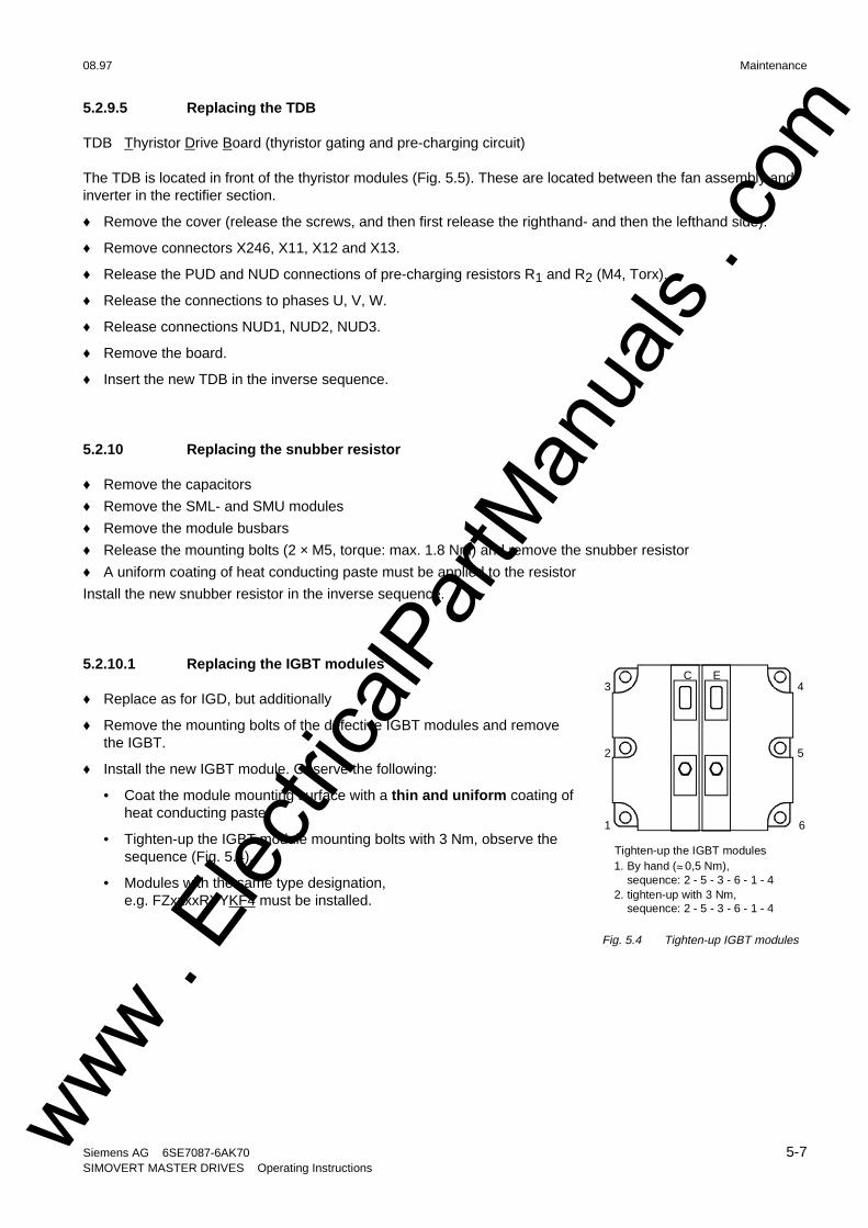
♦ Install the new IGBT module. Observe the following:
• Coat the module mounting surface with a thin and uniform coating ofheat conducting paste.
• Tighten-up the IGBT module mounting bolts with 3 Nm, observe thesequence (Fig. 5.4).
• Modules with the same type designation,e.g. FZxxxxRYYKF4 must be installed.
1
2
3 4
5
6
C E
Tighten-up the IGBT modules1. By hand (≈ 0,5 Nm), sequence: 2 - 5 - 3 - 6 - 1 - 42. tighten-up with 3 Nm, sequence: 2 - 5 - 3 - 6 - 1 - 4
Fig. 5.4 Tighten-up IGBT modules
www . El
ectric
alPar
tMan
uals
. com

Maintenance 08.97
5-8 Siemens AG 6SE7087-6AK70SIMOVERT MASTER DRIVES Operating Instructions
5.2.11 Replacing pre-charging resistors (R1, R2)
These are located to the right next to the TDB board in the rectifier section (Fig. 5.5).
♦ Remove the cover (lossen the screws, then release first the righthand- and then the lefthand side).
♦ Release the PUD and NUD connections of the pre-charging resistors (M4, Torx).
♦ Release and remove the pre-charging resistors.
♦ Install the new pre-charging resistor with a 20 Nm ± 10 % torque.
CAUTION
Don’t bend the pre-charging resistor!
♦ Mounting and connecting-up must be executed in the inverse sequence.
5.2.12 Replacing the thyristor modules (V1 to V3)
Replace as for the TDB, in addition Fig. 5.5
♦ Release C + D− connecting cable of theoptional terminals
♦ Release the C and D busbar connectionsbetween the rectifier and inverter
♦ Release connections U, V, W of themodules
♦ Release the connections between themodules and C(+) busbar
♦ Remove the C(+) connecting lug
♦ Release the connections between themodules and D(−) busbar
♦ Remove the D(−) connecting lug
♦ Release the module retaining bolts(M6, Torx)
♦ Remove the module (weight 500 g)
♦ Clean the contact surface
♦ Apply a thin uniform coating of heatconducting paste to the new module.Tightening torque of the retaining bolt:6 Nm ± 15 %
♦ Mount in the inverse sequence. Tighteningtorque of the electrical connections(C and D): 12 Nm (+ 5 %, − 10 %).
Fig. 5.5 TDB board, pre-charging resistors and thyristor modulesV1, V2, V3
www . El
ectric
alPar
tMan
uals
. com
08.97 Maintenance
Siemens AG 6SE7087-6AK70 5-9SIMOVERT MASTER DRIVES Operating Instructions
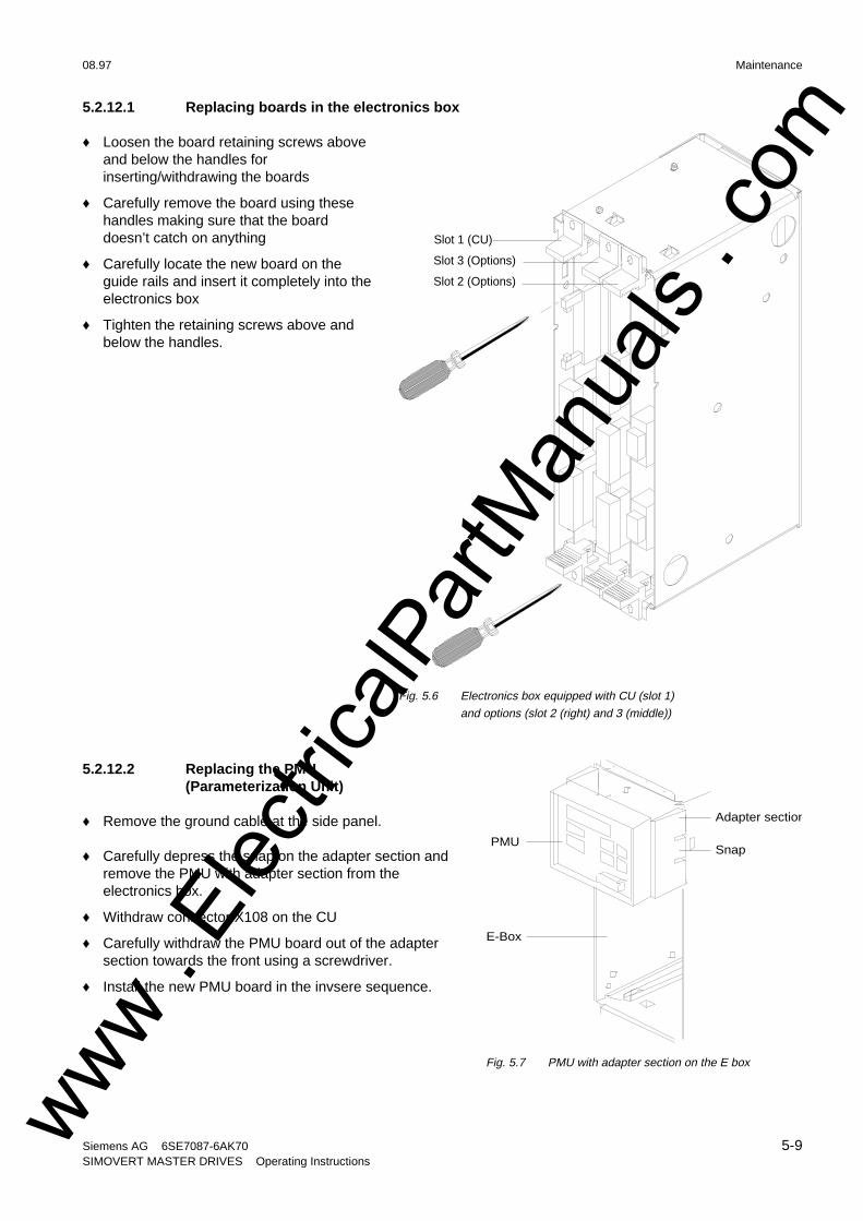
5.2.12.1 Replacing boards in the electronics box
♦ Loosen the board retaining screws aboveand below the handles forinserting/withdrawing the boards
♦ Carefully remove the board using thesehandles making sure that the boarddoesn’t catch on anything
♦ Carefully locate the new board on theguide rails and insert it completely into theelectronics box
♦ Tighten the retaining screws above andbelow the handles.
5.2.12.2 Replacing the PMU(Parameterization Unit)
♦ Remove the ground cable at the side panel.
♦ Carefully depress the snap on the adapter section andremove the PMU with adapter section from theelectronics box.
♦ Withdraw connector X108 on the CU
♦ Carefully withdraw the PMU board out of the adaptersection towards the front using a screwdriver.
♦ Install the new PMU board in the invsere sequence.
Slot 3 (Options)
Slot 1 (CU)
Slot 2 (Options)
Fig. 5.6 Electronics box equipped with CU (slot 1)
and options (slot 2 (right) and 3 (middle))
E-Box
Snap PMU
Adapter section
Fig. 5.7 PMU with adapter section on the E box
www . El
ectric
alPar
tMan
uals
. com

www . El
ectric
alPar
tMan
uals
. com

08.97 Options
Siemens AG 6SE7087-6AK70 6-1SIMOVERT MASTER DRIVES Operating Instructions
6 Options
6.1 Options which can be integrated into the electronics box
One or two option boards, listed in Table 6.1, can be inserted in the electronics box using the LBA option (localbus adapter).
Before installing option boards in the electronics box, theLBA (local Bus Adapter) has to be inserted.
Install the LBA bus expansion:
♦ Remove the CU (lefthand slot in the electronics box)using the handles after first removing the connectingcable to the PMU and both retaining screws.
♦ Insert the LBA bus expansion in the electronics box(position, refer to the diagram) so that it snaps intoplace.
♦ Re-insert the CU into the lefthand slot, screw theretaining screws on the handles tight, and insert theconnecting cable to the PMU.
♦ Insert the option board in slot 2 (right) or slot 3(center) of the electronics box, and screw into place.Each option board may only by inserted in theelectronics box. If only one option is used, it mustalways be inserted at slot 2 (right).
Slots in the electronics box Boards
Left Slot 1 (CU) CU
Center Slot 3 (options) CB1 / SCB1 / SCB2
Right Slots 2 (options) CB1 / SCB1 / SCB2 / TSY / TB
NOTES
♦ Only one of each option board type may inserted in the electronics box.
♦ TB (technology boards, e.g. T300) must always be inserted at slot 2. When a TB board is used, a TSYboard my not be inserted.
♦ If only one option board is used it must always be inserted at slot 2.
Table 6.1 Possible arrangements of boards in the electronics box
Fig. 6.1 Installing the Local Bus Adapter
www . El
ectric
alPar
tMan
uals
. com
Options 08.97
6-2 Siemens AG 6SE7087-6AK70SIMOVERT MASTER DRIVES Operating Instructions
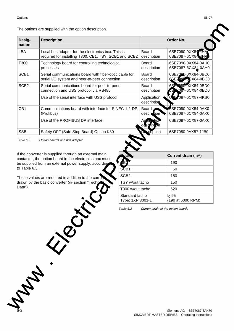
The options are supplied with the option description.
Desig-nation
Description Order No.
LBA Local bus adapter for the electronics box. This isrequired for installing T300, CB1, TSY, SCB1 and SCB2
Boarddescription
6SE7090-0XX84-4HA06SE7087-6CX84-4HA0
T300 Technology board for controlling technologicalprocesses
Boarddescription
6SE7090-0XX84-0AH06SE7087-6CX84-0AH0
SCB1 Serial communications board with fiber-optic cable forserial I/O system and peer-to-peer connection
Boarddescription
6SE7090-0XX84-0BC06SE7087-6CX84-0BC0
SCB2 Serial communications board for peer-to-peerconnection and USS protocol via RS485
Use of the serial interface with USS protocol
Boarddescription
Applicationdescription
6SE7090-0XX84-0BD06SE7087-6CX84-0BD0
6SE7087-6CX87-4KB0
CB1 Communications board with interface for SINEC- L2-DP,(Profibus)
Use of the PROFIBUS DP interface
Boarddescription
Applicationdescription
6SE7090-0XX84-0AK06SE7087-6CX84-0AK0
6SE7087-6CX87-0AK0
SSB Safety OFF (Safe Stop Board) Option K80 Description 6SE7080-0AX87-1JB0
Table 6.2 Option boards and bus adapter
If the converter is supplied through an external maincontactor, the option board in the electronics box mustbe supplied from an external power supply, accordingto Table 6.3.
These values are required in addition to the currentdrawn by the basic converter (+ section “TechnicalData“).
Board Current drain (mA)
CB1 190
SCB1 50
SCB2 150
TSY w/out tacho 150
T300 w/out tacho 620
Standard tachoType: 1XP 8001-1
I0 95(190 at 6000 RPM)
Table 6.3 Current drain of the option boards
www . El
ectric
alPar
tMan
uals
. com
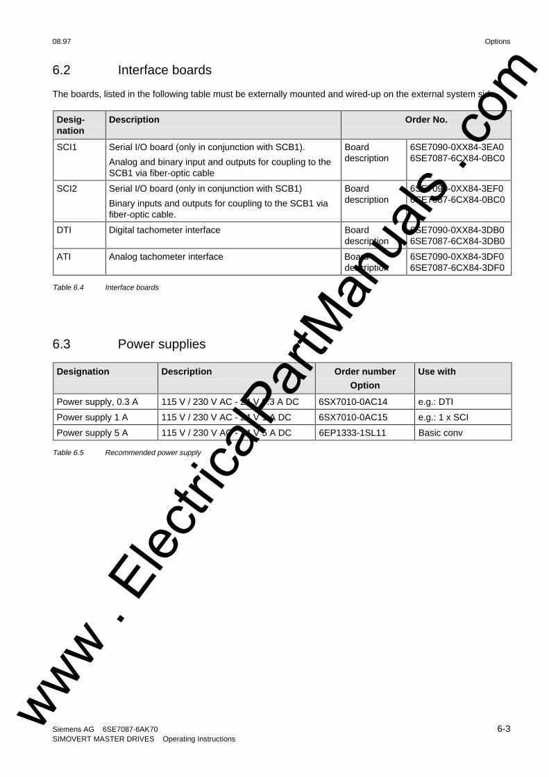
08.97 Options
Siemens AG 6SE7087-6AK70 6-3SIMOVERT MASTER DRIVES Operating Instructions
6.2 Interface boards
The boards, listed in the following table must be externally mounted and wired-up on the external system side.
Desig-nation
Description Order No.
SCI1 Serial I/O board (only in conjunction with SCB1).
Analog and binary input and outputs for coupling to theSCB1 via fiber-optic cable
Boarddescription
6SE7090-0XX84-3EA06SE7087-6CX84-0BC0
SCI2 Serial I/O board (only in conjunction with SCB1)
Binary inputs and outputs for coupling to the SCB1 viafiber-optic cable.
Boarddescription
6SE7090-0XX84-3EF06SE7087-6CX84-0BC0
DTI Digital tachometer interface Boarddescription
6SE7090-0XX84-3DB06SE7087-6CX84-3DB0
ATI Analog tachometer interface Boarddescription
6SE7090-0XX84-3DF06SE7087-6CX84-3DF0
Table 6.4 Interface boards
6.3 Power supplies
Designation Description Order number
Option
Use with
Power supply, 0.3 A 115 V / 230 V AC - 24 V 0.3 A DC 6SX7010-0AC14 e.g.: DTI
Power supply 1 A 115 V / 230 V AC - 24 V 1 A DC 6SX7010-0AC15 e.g.: 1 x SCI
Power supply 5 A 115 V / 230 V AC - 24 V 5 A DC 6EP1333-1SL11 Basic conv
Table 6.5 Recommended power supply
www . El
ectric
alPar
tMan
uals
. com
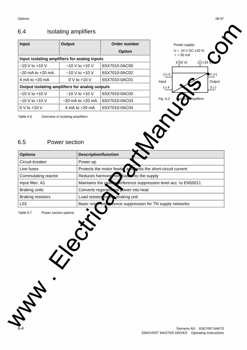
Options 08.97
6-4 Siemens AG 6SE7087-6AK70SIMOVERT MASTER DRIVES Operating Instructions
6.4 Isolating amplifiers
Input Output Order number
Option
Input isolating amplifiers for analog inputs
−10 V to +10 V −10 V to +10 V 6SX7010-0AC00
−20 mA to +20 mA −10 V to +10 V 6SX7010-0AC02
4 mA to +20 mA 0 V to +10 V 6SX7010-0AC01
Output isolating amplifiers for analog outputs
−10 V to +10 V −10 V to +10 V 6SX7010-0AC00
−10 V to +10 V −20 mA to +20 mA 6SX7010-0AC03
0 V to +10 V 4 mA to +20 mA 6SX7010-0AC04
Table 6.6 Overview of isolating amplifiers
6.5 Power section
Options Description/function
Circuit-breaker Power-up
Line fuses Protects the motor feeder and limits the short-circuit current
Commutating reactor Reduces harmonic feedback into the supply
Input filter, A1 Maintains the radio interference suppression level acc. to EN55011
Braking units Converts regenerative power into heat
Braking resistors Load resistor for the braking unit
L03 Basic noise interference suppression for TN supply networks
Table 6.7 Power section options
(+) 5
(-) 4
2 (+)
3 (-)
Input Output
6 (0 V) 1 (+24 V)
Power supply:
V = 24 V DC ±20 % I = 90 mA
Fig. 6.2 Isolating amplifiers
www . El
ectric
alPar
tMan
uals
. com
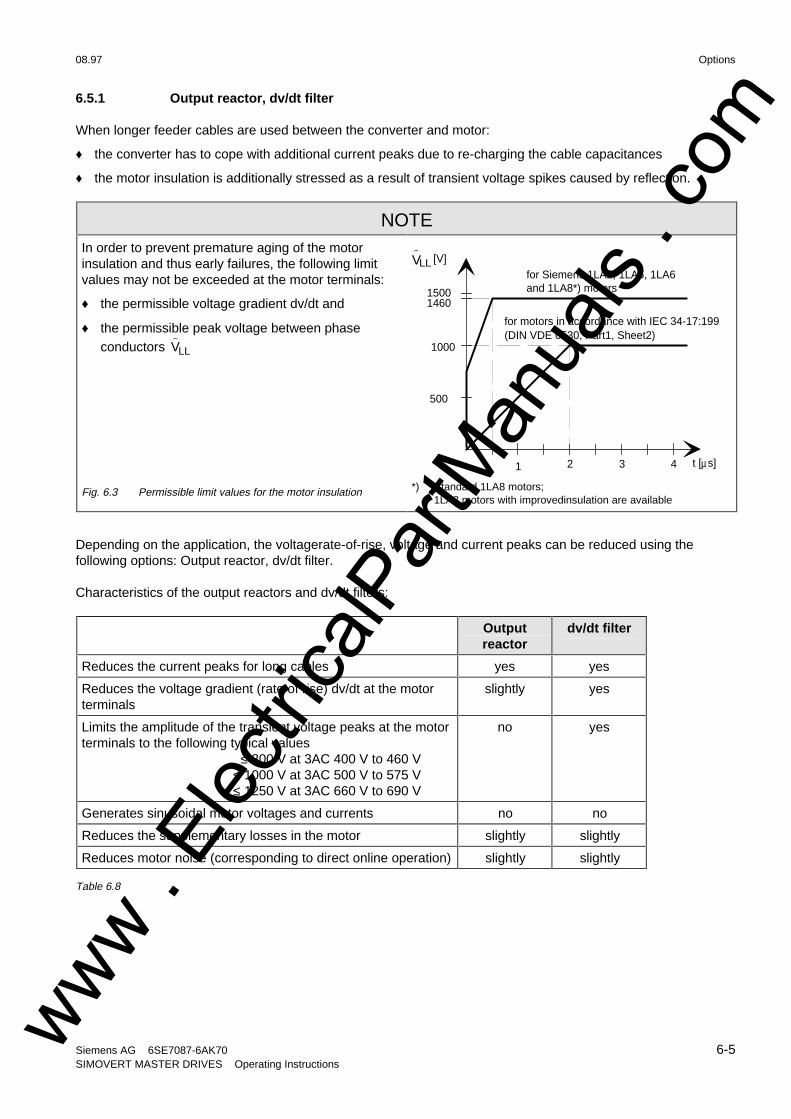
08.97 Options
Siemens AG 6SE7087-6AK70 6-5SIMOVERT MASTER DRIVES Operating Instructions
6.5.1 Output reactor, dv/dt filter
When longer feeder cables are used between the converter and motor:
♦ the converter has to cope with additional current peaks due to re-charging the cable capacitances
♦ the motor insulation is additionally stressed as a result of transient voltage spikes caused by reflection.
NOTEIn order to prevent premature aging of the motorinsulation and thus early failures, the following limitvalues may not be exceeded at the motor terminals:
♦ the permissible voltage gradient dv/dt and
♦ the permissible peak voltage between phaseconductors
)VLL
Fig. 6.3 Permissible limit values for the motor insulation
)VLL
1 2 3 4
500
1000
14601500
t [µ s]
for motors in accordance with IEC 34-17:1992(DIN VDE 0530, Part1, Sheet2)
[V]for Siemens 1LA2, 1LA5, 1LA6and 1LA8*) motors
*) Standard 1LA8 motors;1LA8 motors with improvedinsulation are available
Depending on the application, the voltagerate-of-rise, voltage and current peaks can be reduced using thefollowing options: Output reactor, dv/dt filter.
Characteristics of the output reactors and dv/dt filters:
Outputreactor
dv/dt filter
Reduces the current peaks for long cables yes yes
Reduces the voltage gradient (rate of rise) dv/dt at the motorterminals
slightly yes
Limits the amplitude of the transient voltage peaks at the motorterminals to the following typical values
≤ 800 V at 3AC 400 V to 460 V≤ 1000 V at 3AC 500 V to 575 V≤ 1250 V at 3AC 660 V to 690 V
no yes
Generates sinusoidal motor voltages and currents no no
Reduces the supplementary losses in the motor slightly slightly
Reduces motor noise (corresponding to direct online operation) slightly slightly
Table 6.8
www . El
ectric
alPar
tMan
uals
. com
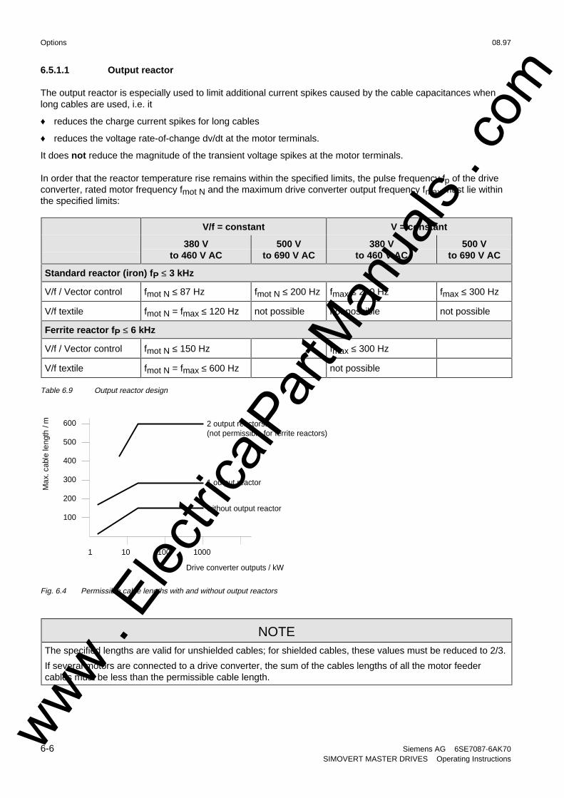
Options 08.97
6-6 Siemens AG 6SE7087-6AK70SIMOVERT MASTER DRIVES Operating Instructions
6.5.1.1 Output reactor
The output reactor is especially used to limit additional current spikes caused by the cable capacitances whenlong cables are used, i.e. it
♦ reduces the charge current spikes for long cables
♦ reduces the voltage rate-of-change dv/dt at the motor terminals.
It does not reduce the magnitude of the transient voltage spikes at the motor terminals.
In order that the reactor temperature rise remains within the specified limits, the pulse frequency fp of the driveconverter, rated motor frequency fmot N and the maximum drive converter output frequency fmax must lie withinthe specified limits:
V/f = constant V = constant
380 Vto 460 V AC
500 Vto 690 V AC
380 Vto 460 V AC
500 Vto 690 V AC
Standard reactor (iron) fP ≤ 3 kHz
V/f / Vector control fmot N ≤ 87 Hz fmot N ≤ 200 Hz fmax ≤ 200 Hz fmax ≤ 300 Hz
V/f textile fmot N = fmax ≤ 120 Hz not possible not possible not possible
Ferrite reactor fP ≤ 6 kHz
V/f / Vector control fmot N ≤ 150 Hz fmax ≤ 300 Hz
V/f textile fmot N = fmax ≤ 600 Hz not possible
Table 6.9 Output reactor design
1 output reactor
2 output reactorss(not permissible for ferrite reactors)
1000100101
100
200
300
400
500
600
Max
. cab
le le
ngth
/ m
Drive converter outputs / kW
without output reactor
Fig. 6.4 Permissible cable lengths with and without output reactors
NOTEThe specified lengths are valid for unshielded cables; for shielded cables, these values must be reduced to 2/3.
If several motors are connected to a drive converter, the sum of the cables lengths of all the motor feedercables must be less than the permissible cable length.
www . El
ectric
alPar
tMan
uals
. com
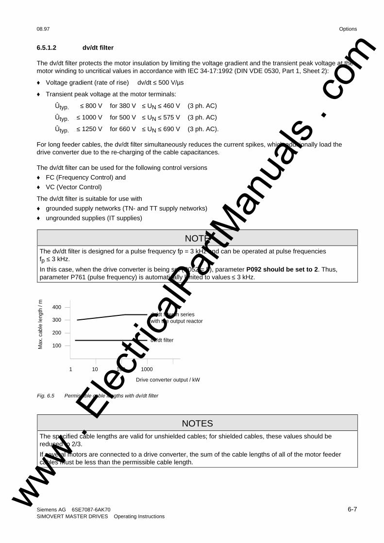
08.97 Options
Siemens AG 6SE7087-6AK70 6-7SIMOVERT MASTER DRIVES Operating Instructions
6.5.1.2 dv/dt filter
The dv/dt filter protects the motor insulation by limiting the voltage gradient and the transient peak voltage at themotor winding to uncritical values in accordance with IEC 34-17:1992 (DIN VDE 0530, Part 1, Sheet 2):
♦ Voltage gradient (rate of rise) dv/dt ≤ 500 V/µs
♦ Transient peak voltage at the motor terminals:
Ûtyp. ≤ 800 V for 380 V ≤ UN ≤ 460 V (3 ph. AC)
Ûtyp. ≤ 1000 V for 500 V ≤ UN ≤ 575 V (3 ph. AC)
Ûtyp. ≤ 1250 V for 660 V ≤ UN ≤ 690 V (3 ph. AC).
For long feeder cables, the dv/dt filter simultaneously reduces the current spikes, which additionally load thedrive converter due to the re-charging of the cable capacitances.
The dv/dt filter can be used for the following control versions
♦ FC (Frequency Control) and
♦ VC (Vector Control)
The dv/dt filter is suitable for use with
♦ grounded supply networks (TN- and TT supply networks)
♦ ungrounded supplies (IT supplies)
NOTEThe dv/dt filter is designed for a pulse frequency fp = 3 kHz and can be operated at pulse frequenciesfp ≤ 3 kHz.
In this case, when the drive converter is being set (P052 = 5), parameter P092 should be set to 2. Thus,parameter P761 (pulse frequency) is automatically limited to values ≤ 3 kHz.
dv/dt filter
1000100101
100
200
300
400
Max
. cab
le le
ngth
/ m
Drive converter output / kW
dv/dt filter in serieswith the output reactor
Fig. 6.5 Permissible cable lengths with dv/dt filter
NOTESThe specified cable lengths are valid for unshielded cables; for shielded cables, these values should bereduced to 2/3.
If several motors are connected to a drive converter, the sum of the cable lengths of all of the motor feedercables must be less than the permissible cable length.
www . El
ectric
alPar
tMan
uals
. com
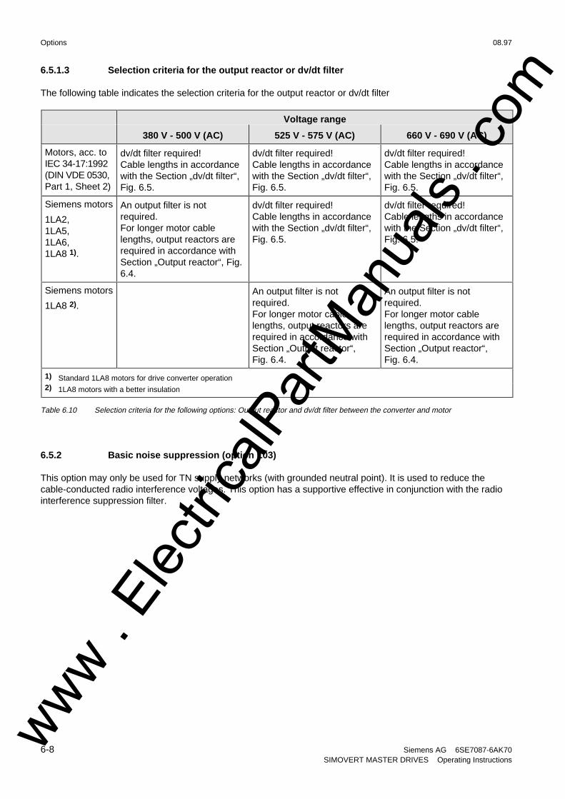
Options 08.97
6-8 Siemens AG 6SE7087-6AK70SIMOVERT MASTER DRIVES Operating Instructions
6.5.1.3 Selection criteria for the output reactor or dv/dt filter
The following table indicates the selection criteria for the output reactor or dv/dt filter
Voltage range
380 V - 500 V (AC) 525 V - 575 V (AC) 660 V - 690 V (AC)
Motors, acc. toIEC 34-17:1992(DIN VDE 0530,Part 1, Sheet 2)
dv/dt filter required!Cable lengths in accordancewith the Section „dv/dt filter“,Fig. 6.5.
dv/dt filter required!Cable lengths in accordancewith the Section „dv/dt filter“,Fig. 6.5.
dv/dt filter required!Cable lengths in accordancewith the Section „dv/dt filter“,Fig. 6.5.
Siemens motors
1LA2,1LA5,1LA6,1LA8 1).
An output filter is notrequired.For longer motor cablelengths, output reactors arerequired in accordance withSection „Output reactor“, Fig.6.4.
dv/dt filter required!Cable lengths in accordancewith the Section „dv/dt filter“,Fig. 6.5.
dv/dt filter required!Cable lengths in accordancewith the Section „dv/dt filter“,Fig. 6.5.
Siemens motors
1LA8 2).
An output filter is notrequired.For longer motor cablelengths, output reactors arerequired in accordance withSection „Output reactor“,Fig. 6.4.
An output filter is notrequired.For longer motor cablelengths, output reactors arerequired in accordance withSection „Output reactor“,Fig. 6.4.
1) Standard 1LA8 motors for drive converter operation2) 1LA8 motors with a better insulation
Table 6.10 Selection criteria for the following options: Output reactor and dv/dt filter between the converter and motor
6.5.2 Basic noise suppression (option L03)
This option may only be used for TN supply networks (with grounded neutral point). It is used to reduce thecable-conducted radio interference voltages. This option has a supportive effective in conjunction with the radiointerference suppression filter.
www . El
ectric
alPar
tMan
uals
. com
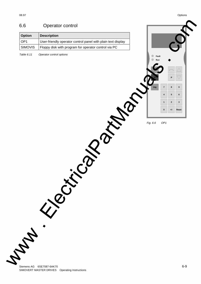
08.97 Options
Siemens AG 6SE7087-6AK70 6-9SIMOVERT MASTER DRIVES Operating Instructions
6.6 Operator control
Option Description
OP1 User-friendly operator control panel with plain text display
SIMOVIS Floppy disk with program for operator control via PC
Table 6.11 Operator control options
P
Fault
Run
0 +/- Reset
1 2 3
654
7 8 9Jog
O
I
Fig. 6.6 OP1
www . El
ectric
alPar
tMan
uals
. com

www . El
ectric
alPar
tMan
uals
. com

08.97 Spare Parts
Siemens AG 6SE7087-6AK70 7-1SIMOVERT MASTER DRIVES Operating Instructions
7 Spare Parts
7.1 Converter 380 V to 460 V 3 AC
Part code No. Designation Order number No. Used in
-G25 PSU2 power supplyboard
6SE7038-6GL84-1JA1 1 6SE7035-1EK206SE7036-0EK20
-A10 CU2 open- and closed-loop control board (VC)
6SE7090-0XX84-0AF0 1 6SE7035-1EK206SE7037-0EK20
-A100, -A110, -A200, -A210, -A300, -A310 IGBT transistor module 6SY7000-0AC77 6 6SE7035-1EK20
6SE7036-0EK20
-A109, -A209, -A309 SMU3 inverter snubberboard
6SE7038-6EK84-1GF0 3 6SE7035-1EK206SE7036-0EK20
-A119, -A219, -A319 SML3 inverter snubberboard
6SE7038-6EK84-1GG0
3 6SE7035-1EK206SE7036-0EK20
-A20 IVI inverter interfaceboard
6SE7038-6GL84-1BG2 1 6SE7035-1EK206SE7036-0EK20
-A26 ABO normalizationboard
6SE7035-1EJ84-1BH0 1 6SE7035-1EK20
-A26 ABO normalizationboard
6SE7036-0TK84-1BH0 1 6SE7036-0EK20
-A29 IGD7 inverter gatingboard
6SE7035-1EJ84-1JC1 1 6SE7035-1EK206SE7036-0EK20
-A30 PMU operatorcontrol/parameterizingunit
6SE7090-0XX84-2FA0 1 6SE7035-1EK06SE7036-0EK20
DC link capacitors,complete with mountingassembly
6SY7000-0AC31 3 6SE7035-1EK20
DC link capacitors,complete with mountingassembly
6SY7000-0AD07 3 6SE7036-0EK20
-C110 MKP capacitor for thefan
6SY7000-0AC35 1 6SE7035-1EK206SE7036-0EK20
-E1 Nozzle for the radial fan 6SY7000-0AB65 1 6SE7035-1EK206SE7036-0EK20
-E1 Radial fan 6SY7000-0AB68 1 6SE7035-1EK206SE7036-0EK20
-F101, -F102 Fused loaddisconnector
6SY7000-0AA26 2 6SE7035-1EK206SE7036-0EK20
-F3, -F4 Fused loaddisconnector
6SY7000-0AC24 2 6SE7035-1EK206SE7036-0EK20
-F3, -F4 Fuse insert 6SY7000-0AC23 2 6SE7035-1EK206SE7036-0EK20
-F101, -F102 Fuse insert 6SY7000-0AB62 2 6SE7035-1EK206SE7036-0EK20
-R100, -R200, -R300 Balancing resistor 6SY9705 3 6SE7035-1EK206SE7036-0EK20
-R100, -R200, -R300 Balancing resistor 6SY7000-0AA76 3 6SE7041-1TK20
-R109, -R119, -R209, -R219, -R309, -R319 Snubber resistor 6SY7000-0AB18 6 6SE7035-1EK206SE7036-0EK20
www . El
ectric
alPar
tMan
uals
. com
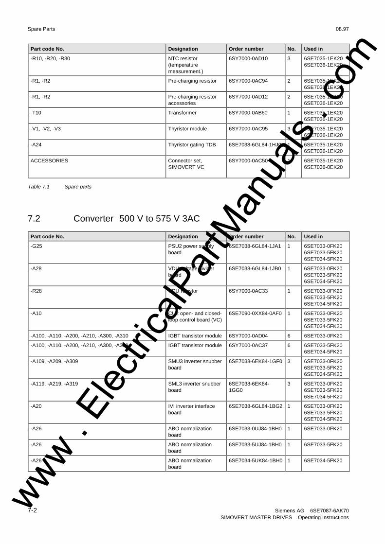
Spare Parts 08.97
7-2 Siemens AG 6SE7087-6AK70SIMOVERT MASTER DRIVES Operating Instructions
Part code No. Designation Order number No. Used in
-R10, -R20, -R30 NTC resistor(temperaturemeasurement.)
6SY7000-0AD10 3 6SE7035-1EK206SE7036-1EK20
-R1, -R2 Pre-charging resistor 6SY7000-0AC94 2 6SE7035-1EK206SE7036-1EK20
-R1, -R2 Pre-charging resistoraccessories
6SY7000-0AD12 2 6SE7035-1EK206SE7036-1EK20
-T10 Transformer 6SY7000-0AB60 1 6SE7035-1EK206SE7036-1EK20
-V1, -V2, -V3 Thyristor module 6SY7000-0AC95 3 6SE7035-1EK206SE7036-1EK20
-A24 Thyristor gating TDB 6SE7038-6GL84-1HJ0 1 6SE7035-1EK206SE7036-1EK20
ACCESSORIES Connector set,SIMOVERT VC
6SY7000-0AC50 1 6SE7035-1EK206SE7036-0EK20
Table 7.1 Spare parts
7.2 Converter 500 V to 575 V 3AC
Part code No. Designation Order number No. Used in
-G25 PSU2 power supplyboard
6SE7038-6GL84-1JA1 1 6SE7033-0FK206SE7033-5FK206SE7034-5FK20
-A28 VDU voltage dividerboard
6SE7038-6GL84-1JB0 1 6SE7033-0FK206SE7033-5FK206SE7034-5FK20
-R28 VDU resistor 6SY7000-0AC33 1 6SE7033-0FK206SE7033-5FK206SE7034-5FK20
-A10 CU2 open- and closed-loop control board (VC)
6SE7090-0XX84-0AF0 1 6SE7033-0FK206SE7033-5FK206SE7034-5FK20
-A100, -A110, -A200, -A210, -A300, -A310 IGBT transistor module 6SY7000-0AD04 6 6SE7033-0FK20
-A100, -A110, -A200, -A210, -A300, -A310 IGBT transistor module 6SY7000-0AC37 6 6SE7033-5FK206SE7034-5FK20
-A109, -A209, -A309 SMU3 inverter snubberboard
6SE7038-6EK84-1GF0 3 6SE7033-0FK206SE7033-5FK206SE7034-5FK20
-A119, -A219, -A319 SML3 inverter snubberboard
6SE7038-6EK84-1GG0
3 6SE7033-0FK206SE7033-5FK206SE7034-5FK20
-A20 IVI inverter interfaceboard
6SE7038-6GL84-1BG2 1 6SE7033-0FK206SE7033-5FK206SE7034-5FK20
-A26 ABO normalizationboard
6SE7033-0UJ84-1BH0 1 6SE7033-0FK20
-A26 ABO normalizationboard
6SE7033-5UJ84-1BH0 1 6SE7033-5FK20
-A26 ABO normalizationboard
6SE7034-5UK84-1BH0 1 6SE7034-5FK20
www . El
ectric
alPar
tMan
uals
. com

08.97 Spare Parts
Siemens AG 6SE7087-6AK70 7-3SIMOVERT MASTER DRIVES Operating Instructions
Part code No. Designation Order number No. Used in
-A29 IGD7 inverter gatingboard
6SE7033-5GJ84-1JC0 1 6SE7033-0FK20
-A29 IGD7 inverter gatingboard
6SE7034-5HK84-1JC0 1 6SE7033-5FK206SE7034-5FK20
-A30 PMU operatorcontrol/parameterizingunit
6SE7090-0XX84-2FA0 1 6SE7033-0FK206SE7033-5FK206SE7034-5FK20
DC link capacitors,complete with mountingassembly
6SY7000-0AD00 3 6SE7033-0FK20
DC link capacitors,complete with mountingassembly
6SY7000-0AC32 3 6SE7033-5FK20
DC link capacitors,complete with mountingassembly
6SY7000-0AD08 3 6SE7034-5FK20
-C110 MKP capacitor for thefan
6SY7000-0AC35 1 6SE7033-0FK206SE7033-5FK206SE7034-5FK20
-E1 Nozzle for the radial fan 6SY7000-0AB65 1 6SE7033-0FK206SE7033-5FK206SE7034-5FK20
-E1 Radial fan 6SY7000-0AB68 1 6SE7033-0FK206SE7033-5FK206SE7034-5FK20
-F101, -F102 Fused loaddisconnector
6SY7000-0AA26 2 6SE7033-0FK206SE7033-5FK206SE7034-5FK20
-F3, -F4 Fused loaddisconnector
6SY7000-0AC24 2 6SE7033-0FK206SE7033-5FK206SE7034-5FK20
-F3, -F4 Fuse insert 6SY7000-0AC23 2 6SE7033-0FK206SE7033-5FK206SE7034-5FK20
-F101, -F102 Fuse insert 6SY7000-0AB62 2 6SE7033-0FK206SE7033-5FK206SE7034-5FK20
-R100, -R200, -R300 Balancing resistor 6SY9705 3 6SE7033-0FK206SE7033-5FK206SE7034-5FK20
-R109, -R119, -R209, -R219, -R309, -R319 Snubber resistor 6SY7000-0AB18 6 6SE7033-0FK206SE7033-5FK206SE7034-5FK20
-R10, -R20, -R30 NTC resistor(temperaturemeasurement)
6SY7000-0AD10 3 6SE7033-0FK206SE7033-5FK206SE7034-5FK20
-R1, -R2 Pre-charging resistor 6SY7000-0AC94 2 6SE7033-0FK206SE7033-5FK206SE7034-5FK20
-R1, -R2 Pre-charging resistoraccessories
6SY7000-0AD12 2 6SE7033-0FK206SE7033-5FK206SE7034-5FK20
-T10 Transformer 6SY7000-0AB73 1 6SE7033-0FK206SE7033-5FK206SE7034-5FK20
-V1, -V2, -V3 Thyristor module 6SY7000-0AC96 3 6SE7033-0FK206SE7033-5FK20
www . El
ectric
alPar
tMan
uals
. com
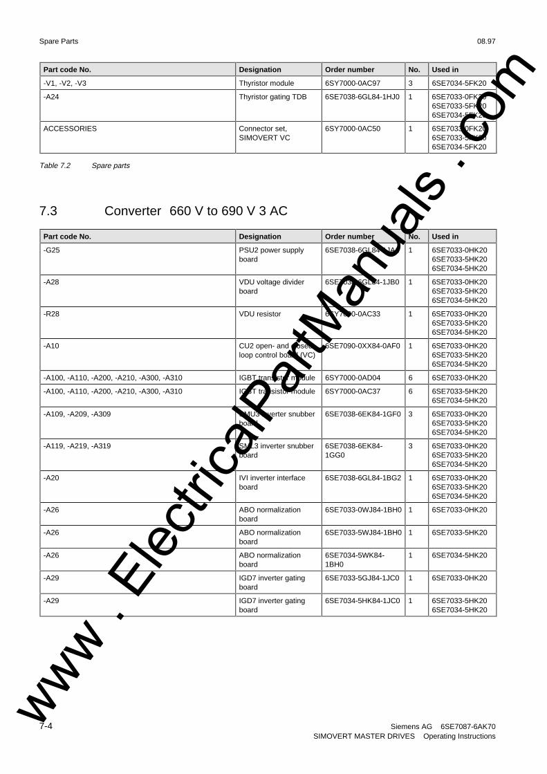
Spare Parts 08.97
7-4 Siemens AG 6SE7087-6AK70SIMOVERT MASTER DRIVES Operating Instructions
Part code No. Designation Order number No. Used in
-V1, -V2, -V3 Thyristor module 6SY7000-0AC97 3 6SE7034-5FK20
-A24 Thyristor gating TDB 6SE7038-6GL84-1HJ0 1 6SE7033-0FK206SE7033-5FK206SE7034-5FK20
ACCESSORIES Connector set,SIMOVERT VC
6SY7000-0AC50 1 6SE7033-0FK206SE7033-5FK206SE7034-5FK20
Table 7.2 Spare parts
7.3 Converter 660 V to 690 V 3 AC
Part code No. Designation Order number No. Used in
-G25 PSU2 power supplyboard
6SE7038-6GL84-1JA1 1 6SE7033-0HK206SE7033-5HK206SE7034-5HK20
-A28 VDU voltage dividerboard
6SE7038-6GL84-1JB0 1 6SE7033-0HK206SE7033-5HK206SE7034-5HK20
-R28 VDU resistor 6SY7000-0AC33 1 6SE7033-0HK206SE7033-5HK206SE7034-5HK20
-A10 CU2 open- and closed-loop control board (VC)
6SE7090-0XX84-0AF0 1 6SE7033-0HK206SE7033-5HK206SE7034-5HK20
-A100, -A110, -A200, -A210, -A300, -A310 IGBT transistor module 6SY7000-0AD04 6 6SE7033-0HK20
-A100, -A110, -A200, -A210, -A300, -A310 IGBT transistor module 6SY7000-0AC37 6 6SE7033-5HK206SE7034-5HK20
-A109, -A209, -A309 SMU3 inverter snubberboard
6SE7038-6EK84-1GF0 3 6SE7033-0HK206SE7033-5HK206SE7034-5HK20
-A119, -A219, -A319 SML3 inverter snubberboard
6SE7038-6EK84-1GG0
3 6SE7033-0HK206SE7033-5HK206SE7034-5HK20
-A20 IVI inverter interfaceboard
6SE7038-6GL84-1BG2 1 6SE7033-0HK206SE7033-5HK206SE7034-5HK20
-A26 ABO normalizationboard
6SE7033-0WJ84-1BH0 1 6SE7033-0HK20
-A26 ABO normalizationboard
6SE7033-5WJ84-1BH0 1 6SE7033-5HK20
-A26 ABO normalizationboard
6SE7034-5WK84-1BH0
1 6SE7034-5HK20
-A29 IGD7 inverter gatingboard
6SE7033-5GJ84-1JC0 1 6SE7033-0HK20
-A29 IGD7 inverter gatingboard
6SE7034-5HK84-1JC0 1 6SE7033-5HK206SE7034-5HK20
www . El
ectric
alPar
tMan
uals
. com
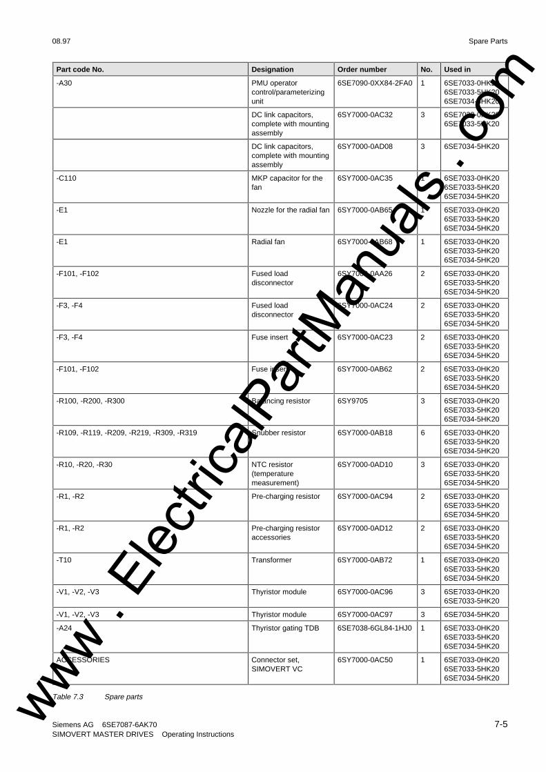
08.97 Spare Parts
Siemens AG 6SE7087-6AK70 7-5SIMOVERT MASTER DRIVES Operating Instructions
Part code No. Designation Order number No. Used in
-A30 PMU operatorcontrol/parameterizingunit
6SE7090-0XX84-2FA0 1 6SE7033-0HK206SE7033-5HK206SE7034-5HK20
DC link capacitors,complete with mountingassembly
6SY7000-0AC32 3 6SE7033-0HK206SE7033-5HK20
DC link capacitors,complete with mountingassembly
6SY7000-0AD08 3 6SE7034-5HK20
-C110 MKP capacitor for thefan
6SY7000-0AC35 1 6SE7033-0HK206SE7033-5HK206SE7034-5HK20
-E1 Nozzle for the radial fan 6SY7000-0AB65 1 6SE7033-0HK206SE7033-5HK206SE7034-5HK20
-E1 Radial fan 6SY7000-0AB68 1 6SE7033-0HK206SE7033-5HK206SE7034-5HK20
-F101, -F102 Fused loaddisconnector
6SY7000-0AA26 2 6SE7033-0HK206SE7033-5HK206SE7034-5HK20
-F3, -F4 Fused loaddisconnector
6SY7000-0AC24 2 6SE7033-0HK206SE7033-5HK206SE7034-5HK20
-F3, -F4 Fuse insert 6SY7000-0AC23 2 6SE7033-0HK206SE7033-5HK206SE7034-5HK20
-F101, -F102 Fuse insert 6SY7000-0AB62 2 6SE7033-0HK206SE7033-5HK206SE7034-5HK20
-R100, -R200, -R300 Balancing resistor 6SY9705 3 6SE7033-0HK206SE7033-5HK206SE7034-5HK20
-R109, -R119, -R209, -R219, -R309, -R319 Snubber resistor 6SY7000-0AB18 6 6SE7033-0HK206SE7033-5HK206SE7034-5HK20
-R10, -R20, -R30 NTC resistor(temperaturemeasurement)
6SY7000-0AD10 3 6SE7033-0HK206SE7033-5HK206SE7034-5HK20
-R1, -R2 Pre-charging resistor 6SY7000-0AC94 2 6SE7033-0HK206SE7033-5HK206SE7034-5HK20
-R1, -R2 Pre-charging resistoraccessories
6SY7000-0AD12 2 6SE7033-0HK206SE7033-5HK206SE7034-5HK20
-T10 Transformer 6SY7000-0AB72 1 6SE7033-0HK206SE7033-5HK206SE7034-5HK20
-V1, -V2, -V3 Thyristor module 6SY7000-0AC96 3 6SE7033-0HK206SE7033-5HK20
-V1, -V2, -V3 Thyristor module 6SY7000-0AC97 3 6SE7034-5HK20
-A24 Thyristor gating TDB 6SE7038-6GL84-1HJ0 1 6SE7033-0HK206SE7033-5HK206SE7034-5HK20
ACCESSORIES Connector set,SIMOVERT VC
6SY7000-0AC50 1 6SE7033-0HK206SE7033-5HK206SE7034-5HK20
Table 7.3 Spare partswww . El
ectric
alPar
tMan
uals
. com

www . El
ectric
alPar
tMan
uals
. com

08.97 Environmental friendliness
Siemens AG 6SE7087-6AK70 8-1SIMOVERT MASTER DRIVES Operating Instructions
8 Environmental friendliness
Environmental aspects during the development
The number of components has been significantly reduced over earlier converter series by the use of highlyintegrated components and the modular design of the complete series. Thus, the energy requirement duringproduction has been reduced.
Special significance was placed on the reduction of the volume, weight and variety of metal and plasticcomponents.
Plastic components:
ABS: PMU support panelLOGO
LDPE: Capacitor ring
PA6.6: Fuse holders, mounting rail, capacitor holder, cableretainer, connecting strips, terminal strip, supports, PMUadapter, covers
PC: Covers
PP: Insulating boardsbus retrofit
PS: Fan housing
UP: Tensioning profileretaining bolts
Halogen-containing flame retardants were, for all essential components, replaced by environmentally-friendlyflame retardants.
Environmental compatibility was an important criterium when selecting the supplied components.
Environmental aspects during production
Purchased components are generally supplied in recyclable packaging materials (board).
Surface finishes and coatings were eliminated with the exception of the galvanized sheet steel side panels.
ASIC devices and SMD devices were used on the boards.
The product is emission-free.
Environmental aspects for disposal
The unit can be broken-down into recyclable mechanical components as a result of the easily releasable screw-and snap connections.
The plastic components and moulded housing are to DIN 54840 and have a recycling symbol.
Units can be disposed of through certified disposal companies. Addresses are available from your local Siemenspartner.
www . El
ectric
alPar
tMan
uals
. com

www . El
ectric
alPar
tMan
uals
. com
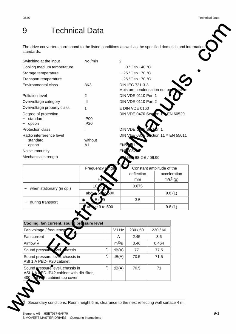
08.97 Technical Data
Siemens AG 6SE7087-6AK70 9-1SIMOVERT MASTER DRIVES Operating Instructions
9 Technical Data
The drive converters correspond to the listed conditions as well as the specified domestic and internationalstandards.
Switching at the input No./min 2
Cooling medium temperature 0 °C to +40 °C
Storage temperature − 25 °C to +70 °C
Transport temperature − 25 °C to +70 °C
Environmental class 3K3 DIN IEC 721-3-3Moisture condensation not permissible
Pollution level 2 DIN VDE 0110 Pert 1
Overvoltage category III DIN VDE 0110 Part 2
Overvoltage property class 1 E DIN VDE 0160Degree of protection− standard− option
IP00IP20
DIN VDE 0470 Section 1 =̂ EN 60529
Protection class I DIN VDE 0106 Section 1
Radio interference level− standard without
DIN VDE 0875 Section 11 =̂ EN 55011
− option A1 EN55011
Noise immunity EN50082-2
Mechanical strength DIN IEC 68-2-6 / 06.90
Frequency range Constant amplitude of thedeflection acceleration
Hz mm m/s2 (g)
− when stationary (in op.)10 to 58
above 58 to 500
0.075
9.8 (1)
− during transport5 to 9
above 9 to 500
3.5
9.8 (1)
Cooling, fan current, sound pressure level
Fan voltage / frequency V / Hz 230 / 50 230 / 60
Fan current A 2.45 3.6
Airflow V m3/s 0.46 0.464
Sound pressure level, chassis *) dB(A) 77 77.5
Sound pressure level, chassis inASI 1 A PED-IP20 cabinet
*) dB(A) 70.5 71.5
Sound pressure level, chassis inASI 1 A PED-IP42 cabinet with dirt filter,400 mm high cabinet top cover
*) dB(A) 70.5 71
*) Secondary conditions: Room height 6 m, clearance to the next reflecting wall surface 4 m.www . El
ectric
alPar
tMan
uals
. com

Technical Data 08.97
9-2 Siemens AG 6SE7087-6AK70SIMOVERT MASTER DRIVES Operating Instructions
Drive converter types
VC 6SE70... 35-1EK20 36-0EK20
Rated voltage, rated frequency, rated current, rated output
Rated voltage in VnInputOutput
V3 AC 380 ... 460 ± 15 %3 AC 0 ... Rated input voltage
Rated frequency fnInputOutput
Hz50/60 ± 6 %VC U/f = const 0 ... 600
U = const 8 ... 300
Rated current InInputOutput
A510510
590590
DC link voltage Vdn V 510...620
Rated output kVA 335...406 388...470
Auxiliary power supply V DC 24 (20-30) (1,8 A without Options; with Options refer to Section 6.1)
Loading Class II acc. to EN 60146-1-1
Rated current A 464 536
Base load time s 240
Overcurrent A 694 802
Overcurrent time s 60
Losses, power factor
Power factorSupply cosϕ1NConverter cosϕU
> 0,98< 0,92 ind.
> 0,98< 0,92 ind.
Efficiency η− Pulse frequency 2,5 kHz 0,980 0,980
Power loss− Pulse frequency 2,5 kHz
kW7.1 at 400 V7.5 at 460 V
8.2 at 400 V8.7 at 460 V
Dimensions, weights
Type K K
WidthHeightDepth
mm 8001750550
8001750550
Weight− IP00
kg455 455
www . El
ectric
alPar
tMan
uals
. com
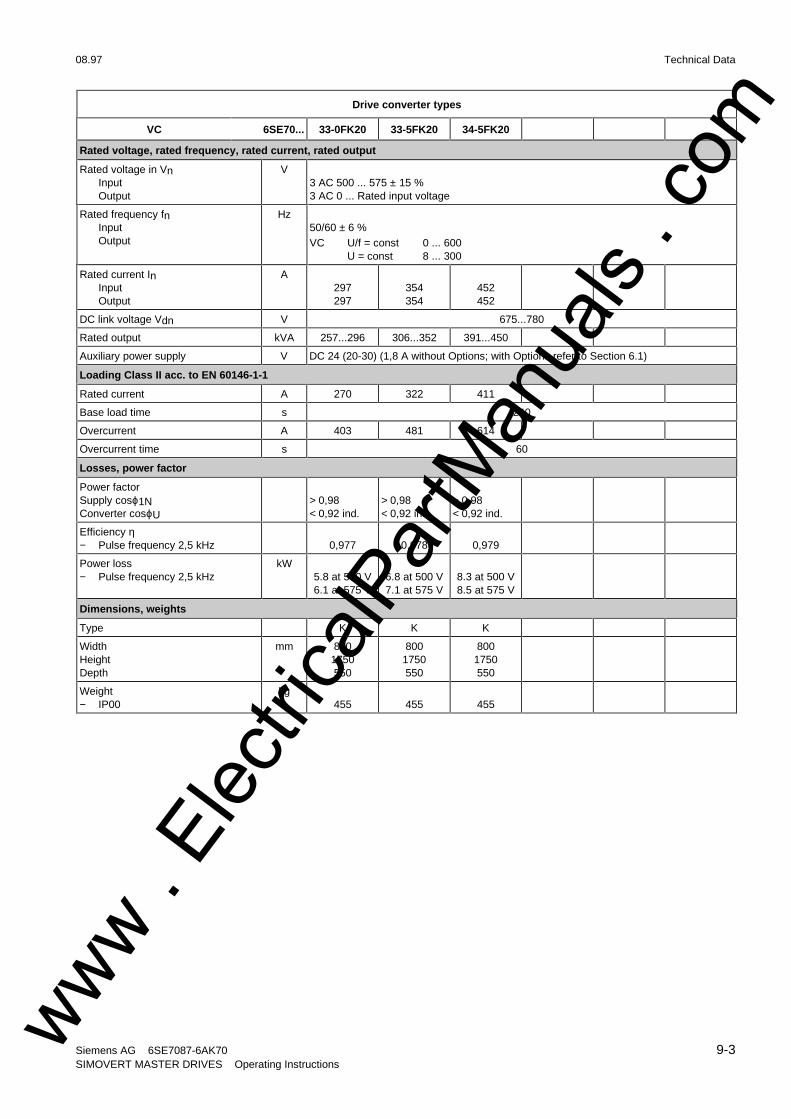
08.97 Technical Data
Siemens AG 6SE7087-6AK70 9-3SIMOVERT MASTER DRIVES Operating Instructions
Drive converter types
VC 6SE70... 33-0FK20 33-5FK20 34-5FK20
Rated voltage, rated frequency, rated current, rated output
Rated voltage in VnInputOutput
V3 AC 500 ... 575 ± 15 %3 AC 0 ... Rated input voltage
Rated frequency fnInputOutput
Hz50/60 ± 6 %VC U/f = const 0 ... 600
U = const 8 ... 300
Rated current InInputOutput
A297297
354354
452452
DC link voltage Vdn V 675...780
Rated output kVA 257...296 306...352 391...450
Auxiliary power supply V DC 24 (20-30) (1,8 A without Options; with Options refer to Section 6.1)
Loading Class II acc. to EN 60146-1-1
Rated current A 270 322 411
Base load time s 240
Overcurrent A 403 481 614
Overcurrent time s 60
Losses, power factor
Power factorSupply cosϕ1NConverter cosϕU
> 0,98< 0,92 ind.
> 0,98< 0,92 ind.
> 0,98< 0,92 ind.
Efficiency η− Pulse frequency 2,5 kHz 0,977 0,978 0,979
Power loss− Pulse frequency 2,5 kHz
kW5.8 at 500 V6.1 at 575 V
6.8 at 500 V7.1 at 575 V
8.3 at 500 V8.5 at 575 V
Dimensions, weights
Type K K K
WidthHeightDepth
mm 8001750550
8001750550
8001750550
Weight− IP00
kg455 455 455
www . El
ectric
alPar
tMan
uals
. com

Technical Data 08.97
9-4 Siemens AG 6SE7087-6AK70SIMOVERT MASTER DRIVES Operating Instructions
Drive converter types
VC 6SE70... 33-0HK20 33-5HK20 34-5HK20
Rated voltage, rated frequency, rated current, rated output
Rated voltage in VnInputOutput
V3 AC 660 ... 690 ±15 %3 AC 0 ... Rated input voltage
Rated frequency fnInputOutput:
Hz50/60 ± 6 %VC U/f = const 0 ... 600
U = const 8 ... 300
Rated current InInputOutput
A297297
354354
452452
DC link voltage Vdn V 890...930
Rated output kVA 339...355 404...423 516...540
Auxiliary power supply V DC 24 (20-30) (1,8 A without Options; with Options refer to Section 6.1)
Loading Class II acc. to EN 60146-1-1
Rated current A 270 322 411
Base load time s 240
Overcurrent A 403 481 614
Overcurrent time s 60
Losses, power factor
Power factorSupply cosϕ1NConverter cosϕU
> 0,98< 0,92 ind.
> 0,98< 0,92 ind.
> 0,98< 0,92 ind.
Efficiency η− Pulse frequency 2,5 kHz 0,980 0,980 0,981
Power loss− Pulse frequency 2,5 kHz
kW 6.6 at 660 V6.6 at 690 V
7.4 at 660 V7.5 at 690 V
8.9 at 660 V9.1 at 690 V
Dimensions, weights
Type K K K
WidthHeightDepth
mm 8001750550
8001750550
8001750550
Weight− IP00
kg455 455 455
www . El
ectric
alPar
tMan
uals
. com
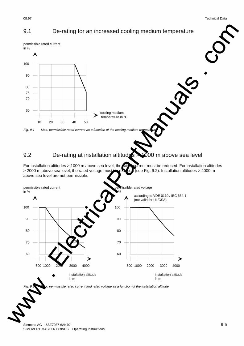
08.97 Technical Data
Siemens AG 6SE7087-6AK70 9-5SIMOVERT MASTER DRIVES Operating Instructions
9.1 De-rating for an increased cooling medium temperature
100
90
80
70
60
10 20 30 40 50
permissible rated current in %
cooling medium temperature in °C
75
Fig. 9.1 Max. permissible rated current as a function of the cooling medium temperature
9.2 De-rating at installation altitudes > 1000 m above sea level
For installation altitudes > 1000 m above sea level, the rated current must be reduced. For installation altitudes> 2000 m above sea level, the rated voltage must be reduced (see Fig. 9.2). Installation altitudes > 4000 mabove sea level are not permissible.
permissible rated currentin %
100
90
80
60
500 1000 2000
installation altitudein m
3000 4000
70
permissible rated voltagein %
100
90
80
60
500 1000 2000 3000 4000
70
installation altitudein m
according to VDE 0110 / IEC 664-1(not valid for UL/CSA)
Fig. 9.2 Max. permissible rated current and rated voltage as a function of the installation altitude
www . El
ectric
alPar
tMan
uals
. com
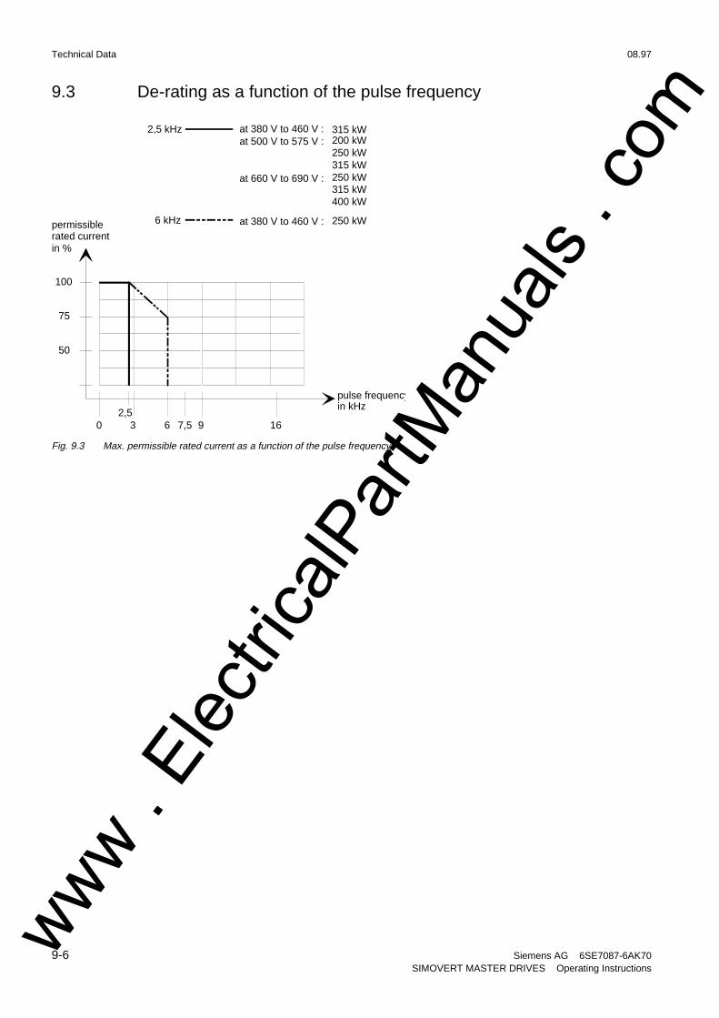
Technical Data 08.97
9-6 Siemens AG 6SE7087-6AK70SIMOVERT MASTER DRIVES Operating Instructions
9.3 De-rating as a function of the pulse frequency
permissiblerated currentin %
100
50
0 3 6 16
75
pulse frequencyin kHz
97,5
6 kHz
2,5 kHz at 380 V to 460 V :at 500 V to 575 V :
at 660 V to 690 V :
200 kW250 kW315 kW250 kW315 kW400 kW
at 380 V to 460 V :
2,5
315 kW
250 kW
Fig. 9.3 Max. permissible rated current as a function of the pulse frequency
www . El
ectric
alPar
tMan
uals
. com
08.97 Appendix
Siemens AG 6SE7087-6AK70 10-1SIMOVERT MASTER DRIVES Operating Instructions
10 Appendix
10.1 Index
− A −
Addresses .........................................................11-1
Applications.........................................................1-1
Auxiliary power supply/main contactor ................3-4
− B −
Basic noise suppression (option L03) .................6-8
− C −
Connecting-up.....................................................3-1
Converter 380 V to 460 V 3 AC...........................7-1
Converter 500 V to 575 V 3AC............................7-2
Converter 660 V to 690 V 3 AC...........................7-4
− D −
DC link connection ..............................................3-4
De-rating as a function of the pulse frequency....9-6
De-rating at installationaltitudes > 1000 m above sea level.....................9-5
De-rating for an increased cooling mediumtemperature.........................................................9-5
Description ..........................................................1-1
Dimension drawing..............................................2-5
Displays.............................................................. 4-2
dv/dt filter.............................................................6-7
− E −
Environmental friendliness ..................................8-1
− I −
Instructions for EMC-correct-installation .............3-5
Interface boards ..................................................6-3
Isolating amplifiers ..............................................6-4
− M −
Maintenance........................................................5-1
Maintenance requirements..................................5-1
Mode of operation ...............................................1-1
Mounting .............................................................2-2
− O −
Operator control.................................................. 4-1
Operator control.................................................. 6-9
Operator control elements .................................. 4-1
Options ............................................................... 6-1
Options which can be integratedinto the electronics box ....................................... 6-1
Output reactor..................................................... 6-6
Output reactor, dv/dt filter ................................... 6-5
− P −
Power connections ............................................. 3-2
Power section ..................................................... 6-4
Power supplies ................................................... 6-3
Protective conductor connection......................... 3-4
− R −
Removing and installing the module busbars ..... 5-4
Replacing boards................................................ 5-5
Replacing boards in the electronics box ............. 5-9
Replacing components ....................................... 5-2
Replacing pre-charging resistors (R1, R2) ......... 5-8
Replacing SML and SMU ................................... 5-3
Replacing the balancing resistor......................... 5-4
Replacing the capacitor bank ............................. 5-3
Replacing the fan assembly................................ 5-2
Replacing the fan transformer (-T10).................. 5-3
Replacing the fan transformer fuses (-F3, -F4)... 5-3
Replacing the fuses (-F101, -F102) .................... 5-2
Replacing the IGBT modules.............................. 5-7
Replacing the IGD .............................................. 5-6
Replacing the IVI ................................................ 5-5
Replacing the PMU (Parameterization Unit)....... 5-9
Replacing the PSU ............................................. 5-6
Replacing the snubber resistor ........................... 5-7
Replacing the starting capacitor ......................... 5-3www . El
ectric
alPar
tMan
uals
. com
Appendix 08.97
10-2 Siemens AG 6SE7087-6AK70SIMOVERT MASTER DRIVES Operating Instructions
Replacing the TDB ..............................................5-7
Replacing the thyristor modules (V1 to V3).........5-8
Replacing the VDU and VDU resistor .................5-6
− S −
Selection criteria for the outputreactor or du/dt filter ............................................6-8
Spare Parts......................................................... 7-1
Storage ............................................................... 2-1
− T −
Technical Data .................................................... 9-1
Transport and unpacking .................................... 2-1
Transport, Unpacking, Installation ...................... 2-1
10.2 List of abbreviations
A Alarm
AA Analog output
AC Alternating current
AE Analog input
AFE Active front end
AS Sequence control
ASIC Application specific integrated circuit
ASM Asynchronous motor
ATI Beliebig sinnvoll/sinnloser Kommentar
AWG American wire gauge
BA Binary output
BC Bypass contactor
BE Binary input
BF Type of construction
CAN Controller area network
CB Communication board (option)
CU Control unit
CUA Control unit AFE (control unit of AFE)
DC Direct current
DPR Dual-port-RAM
DPRAM Dual-port-RAM
EA First run-up
EEPROM Electrically erasable programmable read-only memory
EMC Electromagnetic compatibility
EMF Electromotive force
EPROM Erasable programmable read-only memory
ESD Electrostatic sensitive devices
F Fault
FC Frequency control (control version of SIMOVERT MASTER DRIVES)
FF Fatal fault
www . El
ectric
alPar
tMan
uals
. com
08.97 Appendix
Siemens AG 6SE7087-6AK70 10-3SIMOVERT MASTER DRIVES Operating Instructions
FI Fault current
FSW Fixed setpoint
G/R Basic/reserve
GSST(1/2) Basic drive converter serial interface (1/2)
H High (binary signal level)
HLG Ramp-function generator
HTL High-voltage transistor logic
HW Hardware
I/O Input/output
IGBT Insulated gate bipolar transistor
IGD IGBT gate drive
IVI Inverter interface
KIP Kinetic buffering
L Low (binary signal level)
LBA Local bus adapter (option)
LED Light emitting diode
LSB Least significant bit
MC Main contactor
MDS Motor data set
MLFB Machine-readable product designation (machine-readable designation)
MSB Most significant bit
NN Sea level
OP(1) Operation panel (1)
Par Parameter
PC Personal computer
PEU Power electronic unit
PG Programming unit (programmer)
PKW Parameter ID value
PMU Parameterization unit
PROFIBUS Process field bus
PS Power supply
PSU Power supply unit
PWE Parameter value
PZD Process data
Q Source
RC Combination, resistor ® and capacitor (C)
RDS Reserve data set
RFG Ramp-function generator
SC Servo control (control version of SIMOVERT MASTER DRIVES)
SCB(1/2) Serial communication board (option)
SCI(1/2) Serial communication Interface (1/2)www . El
ectric
alPar
tMan
uals
. com
Appendix 08.97
10-4 Siemens AG 6SE7087-6AK70SIMOVERT MASTER DRIVES Operating Instructions
SDS Setpoint data set
SL Slave
SM Synchronous motor
SMD Surface mounted device
SML Snubber module low
SMU Snubber module up
SST1/2 Serial interface 1/2
SW Software
TB Technology board (option)
TLG Telegram
TRC Trace
TSY Tacho and synchronization (option)
TTL Transistor-Transistor-Logic
UCE Voltage (V) collector->emitter (desaturation signal of the transistors)
UMR Drive converter
USS Universal serial interface
VC Vector control (control version of SIMOVERT MASTER DRIVES)
VDU Voltage-dividing-unit
VS Precharging contactor
Vsa Line supply voltage components in the a axis
Vsb Line supply voltage components in the b axis
VSB voltage sensing board (line supply voltage sensing board)
WEA Automatic restart function
WR Inverter
X9 Terminal strip on the PEU (types A to D), PSU1 (types E to H) and PSU2 (types J to M)
ZK DC link
www . El
ectric
alPar
tMan
uals
. com

08.97 Addresses
Siemens AG 6SE7087-6AK70 11-1SIMOVERT MASTER DRIVES Operating Instructions
11 Addresses
EuropeBELGIUMSiemens S. A.Bruxelles
BULGARIASiemens AG Vertretung inBulgarienSofia
DENMARKSiemens A/SKopenhagen, Ballerup
FINLANDSiemens OsakeyhtiöHelsinki
FRANCESiemens S. A.Paris, Saint-DenisLille, SeclinLyon, Caluire-et-CuireMarseilleMetzStrasbourg
GREECESiemens A. E.Athen, AmaroussioThessalonikiSiemens Industrie A. E.Athen, AmaroussioEviop-Tempo A. E.Vassiliko Evias
GREAT BRITAINSiemens plcLondon, Sunbury-on-ThamesAberdeenBirmingham, WalsallBristol, ClevedonEdinburghGlasgowManchesterBelfast
IRELANDSiemens Ltd.Dublin
ICELANDSmith & Norland H/FReykjavik
ITALYSiemens S. p. A.MilanoBariBolognaBresciaCasoriaFirenzeGenovaPadovaRomaTorino
CROATIASiemens d.o.o.Zagreb
LUXEMBOURGSiemens S. A.Luxembourg
MALTAJ. R. Darmanin & Co., Ltd.Valletta
NETHERLANDSSiemens Nederland N. V.Den Haag
NORWAYSiemens A/SOsloBergen-FyllingsdalenStavangerTrondheim
AUSTRIASiemens AG ÖsterreichWienBregenzEisenstadtGraz-StraßgangInnsbruckKlagenfurtLinzSalzburgSt. Pölten
POLANDSiemens Sp.z.o.o.WarszawaGdanskKatowiceKraków
LódzPoznanWroclaw
PORTUGALSiemens S. A.Lisboa, AmadoraGuia , AlbufeiraCoimbraPorto
ROMANIASiemens birou de consultatiitehniceBucuresti
RUSSIAN FERDERATIONVertretung der Siemens AGMoskau
SWEDENSiemens ABStockholmGöteborgJönköpingMalmöSundsvall
SWITZERLANDSiemens-Albis AGZürichBaselRenens , Lausanne
SLOWAKIAN REP.Siemens s.r.o.Bratislava
SLOVENIASiemens d.o.o.Ljubljana
SPAINSiemens S. A.Madrid
CZECHIA REP.Siemens s.r.o.PrahaBrno
TURKEYSIMKO Ticaret ve Sanayi A.S.IstanbulAdanaAnkaraBursaIzmirSamsun
UKRAINEVertretung der Siemens AGKiew
HUNGARIANSiemens kftBudapest
CYPRUSJolali Ltd.
Nicosia
World
Africa
EGYPTSiemens Technical OfficeCairo-MohandessinAlexandriaELETECHCairo-Zamalek
ETHIOPIAAddis Electrical EngineeringLtd.Addis Abeba
ALGERIASiemens Bureau d’AlgerAlger-Hydra
ANGOLASiemens RepresentativeOfficeLuanda
CÔTE D'IVOIRESiemens AGSuccursalleAbidjan
GHANAINTEL Merchants Ltd.Accra
KENYAInternational CommunicationSystems Ltd.(ICS)Nairobi
LIBYASiemens AGTripoli
MOROCCOSETELSoci‚te Electrotechnique et deTélécommunications S. A.Casablanca
MOZAMBIQUESiemens Liaison OfficeMaputo
NAMIBIASiemens (Pty.) Ltd.Windhoek
NIGERIAElectro Technologies NigeriaLtd. (ELTEC)Lagos
ZAMBIAElectrical Maintenance LusakaLtd. (EML)Lusaka
ZIMBABWEElectro TechnologiesCorporation (Pvt.) Ltd.Harare
SUDANNational Electrical &Commercial Company(NECC)Khartoum
SOUTH AFRICASiemens Ltd.JohannesburgCape TownNewcastlePinetownPort Elizabeth
SWAZILANDSiemens (Pty.) Ltd.Mbabane
TANSANIATanzania Electrical ServicesLtd.Dar-es-Salaam
TUNISIASiemens Bureau de LiaisonTunisSitelec S. A.Ariana
ZAIRESOFAMATEL S. P. R. L.Kinshasa
America
ARGENTINIASiemens S. A.Buenos Aires<F208D>Siemens S.A.SucursalBahia BlancaCórdobaLa PlataLas HerasMar del PlataRosarioTucumán
BOLIVIASociedad Comercial ‚Industrial Hansa Ltda.La Paz
www . El
ectric
alPar
tMan
uals
. com

Addresses 08.97
11-2 Siemens AG 6SE7087-6AK70SIMOVERT MASTER DRIVES Operating Instructions
BRAZILSiemens S. A.São PauloBelémBelo HorizonteBrasiliaCampinasCuritibaFortalezaManausPôrto AlegreRecifeRibeirão Prêto
CHILEINGELSACSantiago de Chile
COSTA RICASiemens S.A.San José
ECUADORSiemens S. A.QuitoOTESA S. A.Guayaquil<F208D>
EL SALVADORSiemens S. A.San Salvador
GUATEMALASiemens S. A.Giudad de Guatemala
HONDURASRepresentaciones Electro-industriales S. de R. L.Tegucigalpa
CANADASiemens Electric Ltd.Montreal, QuébecToronto , Mississauga, Ontario
COLOMBIASiemens S. A.BogotáBarranquillaCali , YumboCartagenaMedellín
MEXICOSiemens S. A. de CVMexico, D.F.AguascalientesChihuahuaCuliacánGómez PalacioGuadalajaraHermosilloLeónMéridaMonterreyPueblaQuerétaroTijuanaVeracruz
NICARAGUASiemens S. A.Managua
PARAGUAYRieder & Cia. S. A. C. I.Asunción
PERUSiemsaLima
URUGUAYConatel S. A.Montevideo
VENEZUELASiemens S. A.CaracasBarquisimetoMaracaiboMaracayMaturinMéridaPorlamarPuerto la CruzPuerto OrdazSan CristobalValencia
UNITED STATES OFAMERICASiemens Energy & AutomationInc.Alpharetta, Georgia
Asia
BAHRAINTransitec GulfManamaoderSiemens Resident EngineersDubai
BANGLADESCHSiemens Bangladesh Ltd.Dhaka
PEOPLE’S REP. OF CHINASiemens AG RepresentationBeijingGuangzhouShanghaiShenyangSiemens Electrical ApparatusLtd.Suzhou
HONGKONGSiemens Ltd.Hong Kong
INDIASiemens LimitedBombayAhmedabadBangaloreCalcuttaMadrasNew DelhiSecunderabadThane
INDONESIARepresentative Siemens AGJakartaP. T. Dian-Graha ElektrikaJakarta
IRANSiemens S.S.K.Teheran
JAPANSiemens K. K.Tokyo
JEMENTihama Tractors &Engineering Co. Ltd.SanaaAviation & EngineeringAgencyAden
JORDANA.R. Kevorkian Co.AmmanF.A. Kettaneh & Co. Ltd.Amman
SOUTH KOREASiemens Ltd.Seoul
KUWAITNational & German Electricaland Electronic Service Co.(NGEECO)Kuwait , Hawalli
LEBANONEts. F. A. Kettaneh S. A.Beyrouth
MALAYSIASiemens ElectricalEngineering Sdn. Bhd.Kuala Lumpur
NEPALAmatya Enterprises (Pvt.) Ltd.Kathmandu
OMANWaleed AssociatesMuscatoderSiemens Resident EngineersDubai
PAKISTANSiemens PakistanEngineering Co. Ltd.KarachiFaisalabadIslamabadLahorePeshawarQuetta
PHILIPPINNESSiemens Inc.Metro ManilaMaschinen + Technik Inc.(MATEC)Metro Manila
QATARTrags Electrical Engineeringand Air Conditioning Co.DohaoderSiemens Resident EngineersDubai
SAUDI ARABIAArabia Electric Ltd.(Equipment)JeddahAl KhobarRiyadh
SINGAPORESiemens (Pte.) Ltd.SingaporeGuthrie Engineering (S) Pte.Ltd.Singapore
SRI LANKADimo LimitedColombo
SYRIAAl-Shatta for TechnicalEngineering (A.S.T.E.)Damascus
TAIWANSiemens Ltd.Taipei
THAILANDAdvanced ElectricalEngineering Systems Ltd.(AEES)-Bangkok
UNITED ARAB EMIRATESElectro Mechanical Est.Abu DhabioderSiemens Resident EngineersAbu DhabiScientechnicDubaioderSiemens Resident EngineersDubai
Australia
Siemens Ltd.MelbourneAdelaideBrisbanePerthSydney
NEW ZEALANDSiemens Limited
Auckland
www . El
ectric
alPar
tMan
uals
. com

08.97 Certificates
Siemens AG 6SE7087-6AK70 12-1SIMOVERT MASTER DRIVES Operating Instructions
12 Certificates
Erlangen, 01.07.1995
• Type
•
AC drive converter
SIMOVERTMASTER DRIVES
6SE70... 1)
475 100.9000.00 QP for size A - D476 100.9000.00 QP for size E - H476 200.9000.00 QP for size J - M
Tests performed: I. Product check
II. Isolation test DIN VDE 0160 draft 04.91, par. 7.6.1CSA 22.2-14.M91, par. 6.8
III. Functional testacc. to DIN VDE 0558,part1
IV. RUN-IN Ambient temperatureDurationScampling
55 °C cycled24 up to 72 hours10 % to 100 %
Test results are documented within the production data file.
ASI 1 PE D F
Schlögel
ASI 1
Drive Technology
•
•
••••
•
•••
Drive and Standard Products Group
Test certificate
Equipment
Order No.:
The routine testing according to these testinstructions
checking of presence of all components acc. toparts list
power supplycustomer terminals and interfacespower conversion sectionprotective and monitoring functions
The equipment complied with the test requirements.
1) For complete type, serial number and technical data please see rating plate.
System-Based
www . El
ectric
alPar
tMan
uals
. com
Certificates 08.97
12-2 Siemens AG 6SE7087-6AK70SIMOVERT MASTER DRIVES Operating Instructions
Drive and Standard Products Group
Confirmation Erlangen, 01.07.1995
This confirms that
Equipment AC drive converter
• Type SIMOVERTMASTER DRIVES
• Order No.: 6SE70...
• Service work in operation is only permissible at the electronics box
• The converter must be switched into a no-voltage condition and isolated from the supply whenreplacing any part/component
• All panels must be closed during operation.
is manufactured in conformance with DIN VDE 0558 Part 2and DIN VDE 0113 Part 6.2.
This equipment fulfills the shock hazard protection requirements according to DIN VDE 0106Part 100 when the following safety rules are observed:
Thus, this equipment conforms to the appropriate regulations in Germany according to VBG 4 §2(2) (VBG is a German regulatory body for safety-related issues).
The local operating regulations (e.g. DIN VDE 0105) must be observed when operatingthe equipment.
ASI 1 PE D T
Dr. Link
ASI 1System-BasedDrive Technology
www . El
ectric
alPar
tMan
uals
. com
08.97 Certificates
Siemens AG 6SE7087-6AK70 12-3SIMOVERT MASTER DRIVES Operating Instructions
ASI 1 D/U 4102x Page 1 of 1
*) acc. to EN 10204 (DIN 50049)
Copyright ( ) SIEMENS AG 1995 All rights reserved
Drives and Standard Products Group
We confirm the conformance of the above designated product with the relevant Standards:
This declaration does not guarantee specific equipment characteristics and features.
Factory certificate *
regarding electromagnetic compatability
4SE.476 000 0001.00 WB EMC
Manufacturer: Siemens Aktiengesellschaft
Business Division Variable-speed drives
Sub-Division Drive systems
Address: Postfach 3269
D-91050 Erlangen
Product name: SIMOVERT
Type 6SE70 chassis units AC-AC and DC-AC
When correctly used, the designated product fulfills all the requirements ofDirective 89/336/EEC regarding electromagnetic compatibility.
Note:
The instrucions relating to EMC-correct installation, correct operation, connecting-upconditions and associated instructions in the product documentation suppliedmust be observed.
Erlangen, 20. 01. 1997
H. Mickal
i. V.
Head of the Drive System Production Unit
EN 61800-3 10-1996
EN 61000-4-2 (old IEC 801-2 )
EN 61000-4-4 (old IEC 801-4 )
EN 61000-4-5 (old IEC 801-5 )
IEC 1000-4-3 (old IEC 801-3 )
EN 55011 (DIN VDE 0875 Part 11)
www . El
ectric
alPar
tMan
uals
. com
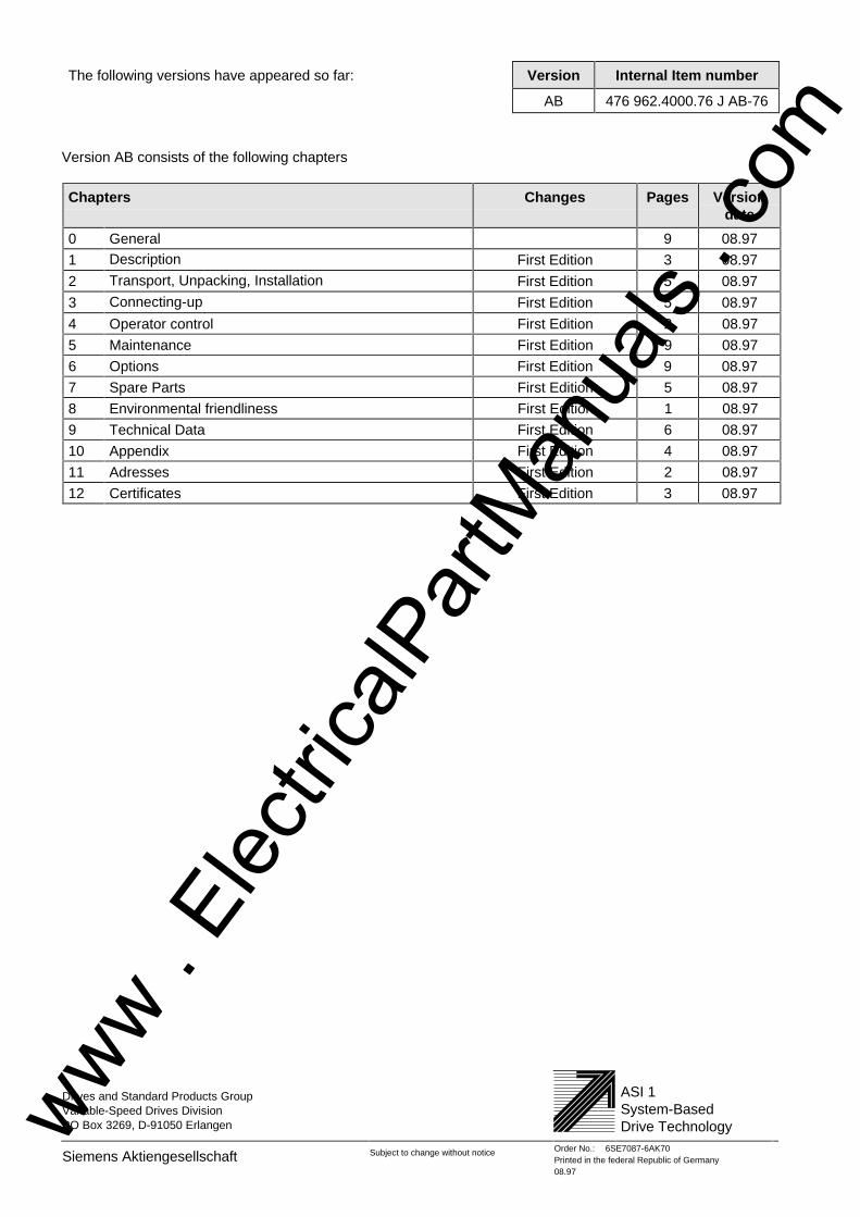
Drives and Standard Products GroupVariable-Speed Drives DivisionPO Box 3269, D-91050 Erlangen
ASI 1System-BasedDrive Technology
Siemens Aktiengesellschaft Subject to change without notice Order No.: 6SE7087-6AK70Printed in the federal Republic of Germany08.97
The following versions have appeared so far: Version Internal Item number
AB 476 962.4000.76 J AB-76
Version AB consists of the following chapters
Chapters Changes Pages Versiondate
0 General 9 08.97
1 Description First Edition 3 08.97
2 Transport, Unpacking, Installation First Edition 5 08.97
3 Connecting-up First Edition 5 08.97
4 Operator control First Edition 2 08.97
5 Maintenance First Edition 9 08.97
6 Options First Edition 9 08.97
7 Spare Parts First Edition 5 08.97
8 Environmental friendliness First Edition 1 08.97
9 Technical Data First Edition 6 08.97
10 Appendix First Edition 4 08.97
11 Adresses First Edition 2 08.97
12 Certificates First Edition 3 08.97
www . El
ectric
alPar
tMan
uals
. com


