Page 1
3-Stage Heat Pump Manual Changeover
Battery or HardwiredSC 2210Non-Programmable Electronic Thermostat
Installation, Operation & Application GuideFor more information on our complete range of American-made products – plus wiring diagrams, troubleshooting tips and more, visit us at www.icmcontrols.com
•Configurable
•ThreeStageHeatPumpSystems
•BacklitDisplay
•FieldCalibrationFeature
•FilterCheck
•RelayOutputs(minimumvoltagedropinthermostat)
•IdeallySuitedfor:–Residential(NewConstruction/Replacement)–LightCommercial
Page 2
Table of ContentsPartsDiagram....................................................................................................................................................... 1Specifications........................................................................................................................................................ 2ImportantSafetyInformation............................................................................................................................... 2PackageContents/ToolsRequired......................................................................................................................... 2ToRemoveExistingThermostat.......................................................................................................................... 3ToInstallThermostat............................................................................................................................................ 3WiringDiagramConversions................................................................................................................................. 5 CarrierSplitStreamCondensersandHeatPumpSystems............................................................................... 5 Coleman3000SeriesHeatPumpSystems....................................................................................................... 6 ComfortMakerCYCSeriesHeatPumpSystems............................................................................................... 7 Heil-Quaker867.814SeriesandPH50SeriesHeatPumpSystems.................................................................. 8 PayneReliantandEnduraModelHeatPumpSystems..................................................................................... 9 Rheem/Ruud:-PGB,-PFA,-PCB,-PLA,and-PKASeriesHeatPumpSystems................................................. 10 Goodman,Janitrol,Trane/AmericanStandardHeatPumps.............................................................................. 11 York-E1CS,-E1FB,-E1FHHeatPumpSystems............................................................................................... 12 LennoxCB19HeatPumpSystems................................................................................................................... 13 LennoxHP19andHP20HeatPumpSystems................................................................................................... 14 LennoxHP21WithCB21PCBHeatPumpSystems.......................................................................................... 15 LennoxHP22WithCB19PCBHeatPumpSystems.......................................................................................... 16 FHP1HeatPumpSystems............................................................................................................................... 17 FHP2HeatPumpSystems............................................................................................................................... 18ConfigurationMode............................................................................................................................................... 19TerminalDesignatorDescriptions.......................................................................................................................... 21SC2210OutputChart............................................................................................................................................ 21StartingtheThermostat....................................................................................................................................... 21LEDIndicators....................................................................................................................................................... 22TestingtheThermostat........................................................................................................................................ 22ModeofOperation................................................................................................................................................ 24Troubleshooting.................................................................................................................................................... 25
Page 4
�
Package Contents/Tools Required
SpecificationsElectricalrating: •24VAC(18-30VAC) • DCPower:3.0VDC(2“AA”batteriesincluded) •1ampmaximumperterminal • 4ampmaximumtotalloadTemperaturecontrolrange:45°Fto90°F(7°Cto32°C)Accuracy:±1°F(±0.5°C)Systemconfigurations:3-stageheat,2-stagecoolheatpumpTiming:Anti-shortCycle:5minutes BacklightOperation:Batteryfor5seconds,hardwiredfor10secondsTerminations:C,L,R,B,O,W2,G,E,Y1,Y2,W3
Important Safety Information
WARNING!:Alwaysturnoffpoweratthemainpowersupplybeforeinstalling,cleaning,orremovingthermostat.
•Thisthermostatisfor24VACapplicationsonly;donotuseonvoltagesover30VAC•Allwiringmustconformtolocalandnationalelectricalandbuildingcodes•Donotuseairconditioningwhentheoutdoortemperatureisbelow50degrees;thiscandamageyour
A/Csystemandcausepersonalinjuries•Usethisthermostatonlyasdescribedinthismanual
Packageincludes: SimpleComfort®2210thermostatonbase,thermostatcover,wiringlabels,screwsandwallanchors,Installation,OperationandApplicationGuide
Toolsrequiredforinstallation:Drillwith3/16”bit,hammer,screwdriver
Page 5
�
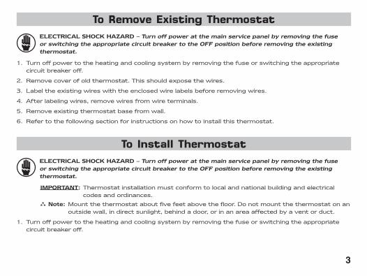
To Remove Existing ThermostatELECTRICALSHOCKHAZARD–TurnoffpoweratthemainservicepanelbyremovingthefuseorswitchingtheappropriatecircuitbreakertotheOFFpositionbeforeremovingtheexistingthermostat.
1. Turnoffpowertotheheatingandcoolingsystembyremovingthefuseorswitchingtheappropriatecircuitbreakeroff.
2. Removecoverofoldthermostat.Thisshouldexposethewires.
3. Labeltheexistingwireswiththeenclosedwirelabelsbeforeremovingwires.
4. Afterlabelingwires,removewiresfromwireterminals.
5. Removeexistingthermostatbasefromwall.
6. Refertothefollowingsectionforinstructionsonhowtoinstallthisthermostat.
To Install ThermostatELECTRICALSHOCKHAZARD–TurnoffpoweratthemainservicepanelbyremovingthefuseorswitchingtheappropriatecircuitbreakertotheOFFpositionbeforeremovingtheexistingthermostat.
IMPORTANT:Thermostatinstallationmustconformtolocalandnationalbuildingandelectricalcodesandordinances.
Note:Mountthethermostataboutfivefeetabovethefloor.Donotmountthethermostatonanoutsidewall,indirectsunlight,behindadoor,orinanareaaffectedbyaventorduct.
1. Turnoffpowertotheheatingandcoolingsystembyremovingthefuseorswitchingtheappropriatecircuitbreakeroff.
Page 6
�
To Install Thermostat (continued)2. Toremovecover,insertandtwistacoinorscrewdriverintheslotsonthesidesofthethermostat.
3. Putthermostatbaseagainstthewallwhereyouplantomountit(Besurewireswillfeedthroughthewireopeninginthebaseofthethermostat).
4. Marktheplacementofthemountingholes.
5. Setthermostatbaseandcoverawayfromworkingarea.
6. Usinga3/16”drillbit,drillholesintheplacesyouhavemarkedformounting.
7. Useahammertotapsuppliedanchorsinmountingholes.
8. Alignthermostatbasewithmountingholesandfeedthecontrolwiresthroughwireopening.
9. Usesuppliedscrewstomountthermostatbasetowall.
10. Insertstripped,labeledwiresinmatchingwireterminals.See“WiringDiagrams”sectionofthismanual(Pages5-18).
CAUTION!:Besureexposedportionofwiresdoesnottouchotherwires.
11. Tightenscrewsonterminalblock.Gentlytugwiretobesureofproperconnection.Doublecheckthateachwireisconnectedtotheproperterminal.
12. Sealholeforwiresbehindthermostatwithnon-flammableinsulationorputty,oruseanICMinsulatedwallplate(ACC-WP01).
13. Replacecoveronthermostatbysnappingitinplace.
14. Turnonpowertothesystematthemainservicepanel.
15. Testthermostatoperationasdescribedin“TestingtheThermostat”(Pages22-24).
Page 7
�
SimpleComfort®2210ElectronicThermostatConversionto:Carrier Split Stream Condensers and Heat Pump Systems
24 VAC, Return
Compressor Contactor
Reversing Valve (Cooling Mode)
Fan Contactor Circuit
Emergency Heating Circuit
2nd Stage Heating Circuit
System Monitor LED
24 VAC, Common
3rd Stage Heating Circuit
R
Y
O
G
E
W2
L
C
W3
Car
rier
Sp
lit S
trea
mL
ow
Vo
ltag
e Te
rmin
al B
oar
d
SC 2210 Electronic Thermostat
Wiring Diagram Conversions
Page 8
�
SC 2210 Electronic Thermostat
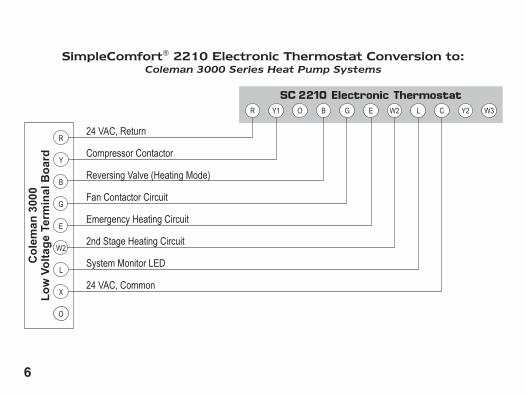
SimpleComfort®2210ElectronicThermostatConversionto:Coleman 3000 Series Heat Pump Systems
24 VAC, Return
Compressor Contactor
Reversing Valve (Heating Mode)
Fan Contactor Circuit
Emergency Heating Circuit
2nd Stage Heating Circuit
System Monitor LED
24 VAC, Common
R
Y
B
G
E
W2
L
X
O
Co
lem
an 3
000
Lo
w V
olt
age
Term
inal
Bo
ard
Page 9
�
SC 2210 Electronic Thermostat
R
Y
O
G
W1
W2
X
C
SimpleComfort®2210ElectronicThermostatConversionto:ComfortMaker CYC Series Heat Pump Systems
24 VAC, Return
Compressor Contactor
Reversing Valve (Cooling Mode)
Fan Contactor Circuit
2nd Stage Heating Circuit
Outdoor Thermostat (Capped)
Defrost Sensor (Capped)
24 VAC, Common
Co
mfo
rtm
aker
CY
CL
ow
Vo
ltag
e Te
rmin
al B
oar
d
Note1:EandW2terminalsjumperedatthermostat. Note2:W2terminalonComfortmakercappedatPCB. Note3:XterminalonComfortmakercappedatPCB.
(capped)
(capped)
Page 10
�
SC 2210 Electronic Thermostat
SimpleComfort®2210ElectronicThermostatConversionto:Heil-Quaker 867.814 Series and PH50 Series Heat Pump Systems
R
Y
O
G
W1
W2
C
24 VAC, Return
Compressor Contactor
Reversing Valve (Cooling Mode)
Fan Contactor Circuit
2nd Stage Heating Circuit (Sequencer 1)
3rd Stage Heating Circuit (Sequencer 2)
24 VAC, Common
Hei
l-Q
uak
er 8
67.8
14 a
nd
PH
50L
ow
Vo
ltag
e Te
rmin
al B
oar
d
Note1:EandW2terminalsjumperedatthermostat.
Page 11
�
SC 2210 Electronic Thermostat
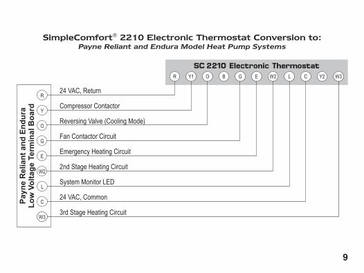
24 VAC, Return
Compressor Contactor
Reversing Valve (Cooling Mode)
Fan Contactor Circuit
Emergency Heating Circuit
2nd Stage Heating Circuit
System Monitor LED
24 VAC, Common
3rd Stage Heating Circuit
R
Y
O
G
E
W2
L
C
W3
Pay
ne
Rel
ian
t an
d E
nd
ura
Lo
w V
olt
age
Term
inal
Bo
ard
SimpleComfort®2210ElectronicThermostatConversionto:Payne Reliant and Endura Model Heat Pump Systems
Page 12
�0
SC 2210 Electronic Thermostat
24 VAC, Return
Compressor Contactor
Reversing Valve (Heating Mode)
Fan Contactor Circuit
2nd Stage Heating Circuit
System Monitor LED
24 VAC, Common
R
Y
B
G
W2
L
X
ORhe
em/R
uud
PG
B, P
FA, P
CB
, PLA
, PK
AL
ow
Vo
ltag
e Te
rmin
al B
oar
dSimpleComfort®2210ElectronicThermostatConversionto:
Rheem/Ruud: -PGB, -PFA, -PCB, -PLA, and -PKA Series Heat Pump Systems
Page 13
��
SC 2210 Electronic Thermostat
R
Y
O
G
X2
W-U
B
T
SimpleComfort®2210ElectronicThermostatConversionto:Goodman, Janitrol, Trane/American Standard Heat Pumps
24 VAC, Return
Compressor Contactor
Reversing Valve (Cooling Mode)
Fan Contactor Circuit
2nd Stage Heating Circuit
24 VAC, Common
Goo
dman
, Jan
itrol
, Tra
ne/A
mer
ican
Sta
ndar
dL
ow
Vo
ltag
e Te
rmin
al B
oar
d
Note1:EandW2terminalsjumperedatthermostat. Note2:X2terminalcappedatPCB. Note3:TterminalcappedatPCB.
(capped)
(capped)
Page 14
��
SC 2210 Electronic Thermostat
SimpleComfort®2210ElectronicThermostatConversionto:York -E1CS, -E1FB, -E1FH Heat Pump Systems
R
Y
O
G
W
X
B
24 VAC, Return
Compressor Contactor
Reversing Valve (Cooling Mode)
Fan Contactor Circuit
2nd Stage Heating Circuit
System Monitor LED
24 VAC, CommonYo
rk -
E1C
S, -
E1F
B, -
E1F
HL
ow
Vo
ltag
e Te
rmin
al B
oar
d
Note1:EandW2terminalsjumperedatthermostat.
Page 15
��
SC 2210 Electronic Thermostat
R
Y
O
G
E
W1
L
C
T
SimpleComfort®2210ElectronicThermostatConversionto:Lennox CB19 Heat Pump Systems
24 VAC, Return
Compressor Contactor
Reversing Valve (Cooling Mode)
Fan Contactor Circuit
Emergency Heating Circuit
2nd Stage Heating Circuit
System Monitor LED
24 VAC, Common
Len
no
x C
B19
Lo
w V
olt
age
Term
inal
Bo
ard
(capped)
Page 16
��
SC 2210 Electronic Thermostat
V-VR
M
R
F
E
Y
X
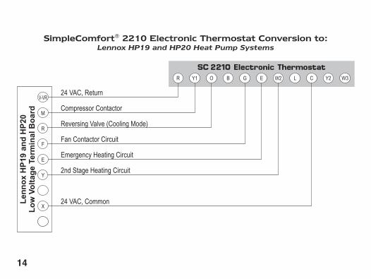
SimpleComfort®2210ElectronicThermostatConversionto:Lennox HP19 and HP20 Heat Pump Systems
24 VAC, Return
Compressor Contactor
Reversing Valve (Cooling Mode)
Fan Contactor Circuit
Emergency Heating Circuit
2nd Stage Heating Circuit
24 VAC, CommonLen
no
x H
P19
an
d H
P20
Lo
w V
olt
age
Term
inal
Bo
ard
Page 17
��
SC 2210 Electronic Thermostat
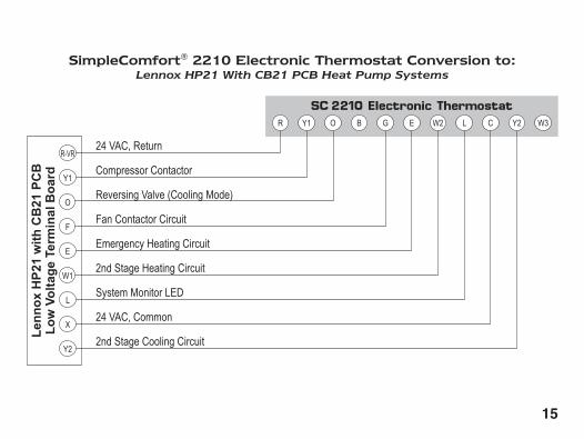
SimpleComfort®2210ElectronicThermostatConversionto:Lennox HP21 With CB21 PCB Heat Pump Systems
R-VR
Y1
O
F
E
W1
L
X
Y2
24 VAC, Return
Compressor Contactor
Reversing Valve (Cooling Mode)
Fan Contactor Circuit
Emergency Heating Circuit
2nd Stage Heating Circuit
System Monitor LED
24 VAC, Common
2nd Stage Cooling Circuit
Len
no
x H
P21
wit
h C
B21
PC
BL
ow
Vo
ltag
e Te
rmin
al B
oar
d
Page 18
��
SC 2210 Electronic Thermostat
R-VR
M
R
F
E
Y
L
X
Y2
Len
no
x H
P22
wit
h C
B19
PC
BL
ow
Vo
ltag
e Te
rmin
al B
oar
dSimpleComfort®2210ElectronicThermostatConversionto:
Lennox HP22 With CB19 PCB Heat Pump Systems
24 VAC, Return
Compressor Contactor
Reversing Valve (Cooling Mode)
Fan Contactor Circuit
Emergency Heating Circuit
2nd Stage Heating Circuit
System Monitor LED
24 VAC, Common
2nd Stage Cooling Circuit
Page 19
��
SC 2210 Electronic Thermostat
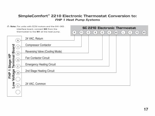
SimpleComfort®2210ElectronicThermostatConversionto:FHP 1 Heat Pump Systems
R
Y
O
G
E
W
C
24 VAC, Return
Compressor Contactor
Reversing Valve (Cooling Mode)
Fan Contactor Circuit
Emergency Heating Circuit
2nd Stage Heating Circuit
24 VAC, Common
FH
P 1
Sta
ge
HP
Lo
w V
olt
age
Term
inal
Bo
ard
Note:ForunitswithECMmotorsandthe641-065interfaceboard,connectW2fromthethermostattotheW1attheheatpump.
Page 20
��
SC 2210 Electronic Thermostat
R
Y
O
G
C
Y2
FH
P 2
Sta
ge
HP
Lo
w V
olt
age
Term
inal
Bo
ard
SimpleComfort®2210ElectronicThermostatConversionto:FHP 2 Heat Pump Systems
24 VAC, Return
Compressor 1 Contactor
Reversing Valve (Cooling Mode)
Fan Contactor Circuit
24 VAC, Common
Compressor 2 Contactor
Note1: JumperfromW2toY2for2compressorsystemswithoutelectricheat.
Page 21
��
TheconfigurationmodeisusedtosettheSC2210tomatchyourheating/coolingsystem.TheSC2210functionswithupto3-stageheatpumpsystems.
ToconfiguretheSC2210,performthefollowingsteps:1. SlidetheModeswitchtotheOFFposition.2. Removethecoverofthethermostatbygentlypullingononeofthecorners.3. SimultaneouslyholdtheSW5andSW6buttonsinfor5secondswhiletheSC2210isinOFFmode.4. Pressthe or buttontochangesettingswithineachscreen.5. PresstheSW6buttontoadvancetothenextscreen. Note:TheSW5buttonwillreturnyoutothepreviousscreen.6. Toexitconfigurationmode,slidetheModeswitchtoHeatorCool.
ConfigurationModeSettingsThesetupscreensforConfigurationModeareasfollows:
1. TemperatureScale(ForC)–ChooseFahrenheitorCelsius. Pressthe or buttontoselect. PresstheSW6buttontoadvancetothenextscreen. FILTER
DIFFROOM
SET REMOTE
FILTERDIFF
ROOMSET REMOTE
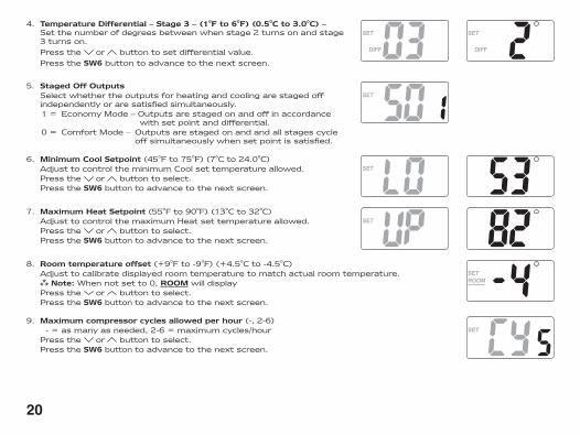
3. TemperatureDifferential–Stage2–(1°Fto6°F)(0.5°Cto3.0°C)–Setthenumberofdegreesbetweenwhenstage1turnsonandstage2turnson.
Pressthe or buttontosetdifferentialvalue. PresstheSW6buttontoadvancetothenextscreen.
FILTERDIFF
ROOMSET REMOTE
FILTERDIFF
ROOMSET REMOTE
2. TemperatureDifferential–Stage1–(1°Fto3°F)(0.5°Cto1.5°C)–Setthenumberofdegreesbetweenyour“setpoint”temperatureandyour“turnon”temperatureforfirststage.
Pressthe or buttontosetdifferentialvalue. PresstheSW6buttontoadvancetothenextscreen.
FILTERDIFF
ROOMSET REMOTE
Configuration Mode
Page 22
�0
FILTERDIFF
ROOMSET REMOTE
9. Maximumcompressorcyclesallowedperhour(-,2-6) -=asmanyasneeded,2-6=maximumcycles/hour Pressthe or buttontoselect. PresstheSW6buttontoadvancetothenextscreen.
FILTERDIFF
ROOMSET REMOTE
8. Roomtemperatureoffset(+9°Fto-9°F)(+4.5°Cto-4.5°C) Adjusttocalibratedisplayedroomtemperaturetomatchactualroomtemperature. Note:Whennotsetto0,ROOMwilldisplay Pressthe or buttontoselect. PresstheSW6buttontoadvancetothenextscreen.
FILTERDIFF
ROOMSET REMOTE
FILTERDIFF
ROOMSET REMOTE
7. MaximumHeatSetpoint(55°Fto90°F)(13°Cto32°C) AdjusttocontrolthemaximumHeatsettemperatureallowed. Pressthe or buttontoselect. PresstheSW6buttontoadvancetothenextscreen.
FILTERDIFF
ROOMSET REMOTE
FILTERDIFF
ROOMSET REMOTE
6. MinimumCoolSetpoint(45°Fto75°F)(7°Cto24.0°C) AdjusttocontroltheminimumCoolsettemperatureallowed. Pressthe or buttontoselect. PresstheSW6buttontoadvancetothenextscreen.
FILTERDIFF
ROOMSET REMOTE
4. TemperatureDifferential–Stage3–(1°Fto6°F)(0.5°Cto3.0°C)–Setthenumberofdegreesbetweenwhenstage2turnsonandstage3turnson.
Pressthe or buttontosetdifferentialvalue. PresstheSW6buttontoadvancetothenextscreen.
5. StagedOffOutputs Selectwhethertheoutputsforheatingandcoolingarestagedoff
independentlyoraresatisfiedsimultaneously. 1= EconomyMode–Outputsarestagedonandoffinaccordance
withsetpointanddifferential. 0= ComfortMode– Outputsarestagedonandandallstagescycle
offsimultaneouslywhensetpointissatisfied.
FILTERDIFF
ROOMSET REMOTE
FILTERDIFF
ROOMSET REMOTE
Page 23
��
10. FilterChecktime(300-800,–––) SetFanRunTime(inhours)whenCheckFilterisdisplayedorsetto–––todisable. Pressthe or buttontoselect. Note: Afterexitingconfigurationmode,toresetfiltercountertozeroandclear filter
warning,pressthe and buttonsimultaneouslyfor5seconds. PresstheSW6buttontoreviewsettings. SlidetheModeswitchtoHeatorCooltoexitconfiguration.
FILTERDIFF
ROOMSET REMOTE
(800Hours)
CAUTION!: Donotuseairconditioningwhentheoutdoortemperatureisbelow50degrees.Thiscandamageyourairconditioningsystemandcausepersonalinjuries.
1. MovetheFanAuto/OnswitchtotheAutoposition.2. MovetheCool/Off/Heat/EmerswitchtoCoolorHeat,
dependingontheseason.FILTER
DIFFROOMSET REMOTE
Starting the Thermostat
R – 24VAChot C – 24VACcommon O – coolactivereversingvalve B – heatactivereversingvalve Y1 – 1ststagecool,1ststageheat W2 – 2ndstageheat
Y2 – 2ndstagecoolfor2compressorsystems G – Fan W3 – 3rdstageheat L – Checkindicator E – 1ststageemergency
Terminal Designator Descriptions
1ST Cool 2ND Cool 1ST Heat 2ND Heat 3RD HeatHeatPump Y1,G,O Y1,Y2,G,O Y1,G,B Y1,W2,G,B Y1,W2,W3,G,B
EmergencyHeatHP N/A N/A E,G E,W2,G E,W2,W3,G
SC2210 Output Chart
Page 24
��
TherearethreeLEDindicatorslocatedonthefrontofthethermostat.Theyaredesignedtoinformyouaboutthefollowing:
LED Color Function
AUX Green •Thisturnsonwhentheauxiliary(secondstage)heatingisinoperation•Itturnson1-6°Fbelowfirststageandisuseradjustable(see
Configuration,Step3,Page19)
CHECK Red •Whenthisturnson,amalfunctionhasoccurredsomewhereintheheatpumpsystem
•Pleasecontactaqualifiedservicetechnicianassoonaspossibletocheckyoursystem
EMER Red •Thislightturnsonwhenevertheemergencyheatismanuallyselected(ModeswitchisintheEMERposition)
•WhileintheemergencyHeatmode,theheatpumpcompressorisoff,andtheemergencyheat(sameastheauxiliaryheat)maintainsthesetpointtemperature
Oncethethermostatisinstalled,itshouldbethoroughlytested.
CAUTION!:Donotenergizetheairconditioningsystemwhentheoutdoortemperatureisbelow50degrees.Itcanresultinequipmentdamageorpersonalinjury.
Testing the Thermostat
LED Indicators
Page 25
��
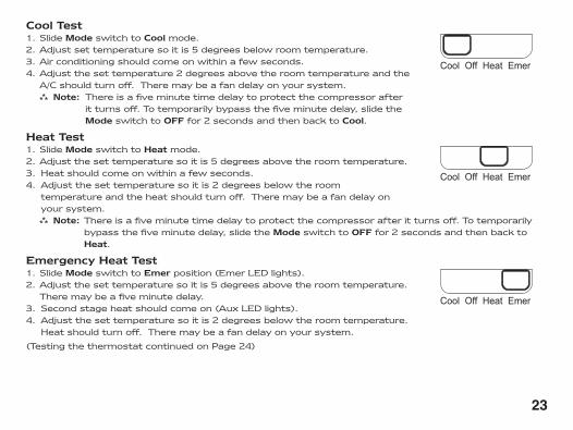
CoolTest1.SlideModeswitchtoCoolmode.2.Adjustsettemperaturesoitis5degreesbelowroomtemperature.3.Airconditioningshouldcomeonwithinafewseconds.4.Adjustthesettemperature2degreesabovetheroomtemperatureandthe
A/Cshouldturnoff.Theremaybeafandelayonyoursystem. Note: Thereisafiveminutetimedelaytoprotectthecompressorafter
itturnsoff.Totemporarilybypassthefiveminutedelay,slidetheModeswitchtoOFFfor2secondsandthenbacktoCool.
HeatTest1.SlideModeswitchtoHeatmode.2.Adjustthesettemperaturesoitis5degreesabovetheroomtemperature.3. Heatshouldcomeonwithinafewseconds.4. Adjustthesettemperaturesoitis2degreesbelowtheroom
temperatureandtheheatshouldturnoff.Theremaybeafandelayonyoursystem.
Note:Thereisafiveminutetimedelaytoprotectthecompressorafteritturnsoff.Totemporarilybypassthefiveminutedelay,slidetheModeswitchtoOFFfor2secondsandthenbacktoHeat.
EmergencyHeatTest1.SlideModeswitchtoEmerposition(EmerLEDlights).2.Adjustthesettemperaturesoitis5degreesabovetheroomtemperature.
Theremaybeafiveminutedelay.3. Secondstageheatshouldcomeon(AuxLEDlights).4. Adjustthesettemperaturesoitis2degreesbelowtheroomtemperature.
Heatshouldturnoff.Theremaybeafandelayonyoursystem.
(TestingthethermostatcontinuedonPage24)
Cool Off Heat Emer
Cool Off Heat Emer
Cool Off Heat Emer
Page 26
��
FanTest1.SlideFanswitchtoOnposition.
2. Indoorfanturnson.Auto OnAuto On
3. SlideFanswitchtoAutoposition.
4. Indoorfanturnsoff.
(TestingthethermostatcontinuedfromPage23)
TheSC2210isamulti-stage,heatpumpthermostat.TheSC2210canuse24VACorbatteriesasapowersupply.TheSC2210canbehardwiredandhavenobatteriesinstalledinthebatterycompartment.Itcanalsorunonbatterypoweronly.Whenbatteriesareinstalledandthethermostatishardwired,thebatterieswillrunthethermostatduringapoweroutage.Whenoperatingonbatterypower,thebacklightwillbeonfor5secondintervals.Whenhardwired,thebacklightwillbeonfor10secondintervals.Thethermostatactivatestheheatpumpwhentheroomtemperatureisbelowtheheatsettemperature(bythedifferentialtemperature).Auxiliaryheatwillbeactivatediftheroomtemperaturecontinuestodrop.Thirdstageheatisactivated(onsomesystems)ifthetemperaturedropsfurther.Theheatoutputsarestagedoff(configurable,setting5,Page20)astheroomtemperatureincreases.Thethermostatwillnotletthecompressorcomeonforfiveminutesafteritturnsoff.Thisprotectsyourcompressor.Whentheroomtemperatureisgreaterthanthecoolsettemperature(bythedifferentialtemperature),thecoolingdeviceisactivated.Second-stagecoolingwillbeactivatediftheroomtemperaturecontinuestorise.Thecooloutputsarestagedoff(configurable,setting5,Page20)astheroomtemperaturedecreases.Thethermostatwillnotletthecompressorcomeonforfiveminutesafteritturnsoff.Thisprotectsyourcompressor.TheSC2210hasthefollowingoperatingmodes:OFF,Heat,EmergencyHeatandCool.InOFFmode,thethermostatwillnotturnonheatingorcoolingdevices.IntheHeatmode,thethermostatcontrolstheheatpumpsystem.IntheEmergencyHeatmode,theheatpumpisbypassedandauxiliarybecomestheprimaryheatsource.IntheCoolmode,thethermostatcontrolsthecoolingsystem.TheindoorfancanbeturnedoninalloperatingmodesusingtheFanswitch.
TheSC2210hasanairfiltercheckoptionalso.Whenthefanruntimeexceedsthetimesetintheconfig-uration(step10,page21),the filterreminderwillbedisplayed.Toresetthe filtercountertozeroandclearthe filterreminderfromthedisplay,pressthe and buttonsinsimultaneouslyfor5seconds.
Mode of Operation
Page 27
��
Symptom RemedyNodisplay ForHardwiredInstallation
Checkfor24VACatthermostat;displayisblankwhen24VACisnotpresentForBatteryInstallationDisplayisblankwhenbatteriesaredrainedorinstalledincorrectly
Systemfandoesnotcomeonproperly
Verifywiringiscorrect
Thermostatturnsonandofftoofrequently
Adjusttemperaturedifferential(see“TemperatureDifferential,”Stage1,Step2,Page19)
Fanrunscontinuously CheckfanOn/Autoswitch,ONpositionrunsindoorfancontinuously
Roomtemperatureisnotcorrect Verifywallholeispluggedwithputtyorinsulation;calibratethermostat(see“Configuration,”Step8,Page20)
ROOMdisplays Roomtemperatureoffsetisnotzero(see“Configuration,”Step8,Page20)
filterdisplays Fanruntimehasexceededfilterchecktimesetinconfiguration(see“Configuration,”Step10,Page21)
Toresetcountertozeroandclear filterwarning,pressthe and buttonsimultaneouslyfor5seconds
Auxiliaryheatnotonsoonenough
Adjustdifferentialfor2ndand3rdstageheatingifrequired(seeConfiguration,Steps3and4,Pages19-20)
Problemnotlistedabove PresstheResetbuttononce;displaywillberefreshedandanti-shortcycletimingwillberesettozero
Troubleshooting
Page 28
ONE-YEAR LIMITED WARRANTYTheSellerwarrantsitsproductsagainstdefectsinmaterialorworkmanshipforaperiodofone(1)yearfromthedateofmanufacture.TheliabilityoftheSellerislimited,atitsoption,torepair,replaceorissueanon-casecreditforthepurchasepricesofthegoodswhichareprovidedtobedefective.ThewarrantyandremediessetforthhereindonotapplytoanygoodsorpartsthereofwhichhavebeensubjectedtomisuseincludinganyuseorapplicationinviolationoftheSeller’sinstructions,neglect,tampering,improperstorage,incorrectinstallationorservicingnotperformedbytheSeller.InordertopermittheSellertoproperlyadministerthewarranty,theBuyershall:1)NotifytheSellerpromptlyofanyclaim,submittingdatecodeinformationoranyotherpertinentdataasrequestedbytheSeller.2)PermittheSellertoinspectandtesttheproductclaimedtobedefective.ItemsclaimedtobedefectiveandaredeterminedbySellertobenon-defectivearesubjecttoa$30.00perhourinspectionfee.ThiswarrantyconstitutestheSeller’ssoleliabilityhereunderandisinlieuofanyotherwarrantyexpressed,impliedorstatutory.Unlessotherwisestatedinwriting,Sellermakesnowarrantythatthegoodsdepictedordescribedhereinarefitforanyparticularpurpose.
LIA200-2
Patent No. ���,������� William Barry Blvd., North Syracuse, NY �����
(Toll Free) 800-365-5525 (Phone) 315-233-5266 (Fax) 315-233-5276
www.icmcontrols.com