27
SIMPLE SAVER SYSTEM ® INSTALL INSTRUCTIONS Call Toll-free: 1-800-255-0776 Fax: 1-402-454-2708 E-mail us at: [email protected] NEW CONSTRUCTION ROOF DETAILS

SIMPLE SAVER SYSTEM®
INSTALL INSTRUCTIONSCall Toll-free: 1-800-255-0776 Fax: 1-402-454-2708E-mail us at: [email protected]
NEW CONSTRUCTION ROOF DETAILS

2 Copyright © 2009 Thermal Design, Inc. All Rights Reserved. SSS_InstallInstructions.indd AK 4/18/09 1-800-255-0776
SIMPLE SAVER SYSTEM® INSTALL INSTRUCTIONSBY THERMAL DESIGN
Thermal Design is the nation’s leader in the ongoing development of thermal insulation technologies for pre-engineered and other non-residential buildings.
Born out of a successful contracting business, Thermal Design brought together practical methodology and cost efficient materials to solve the problems of insulating pre-engineered buildings. With well over 35,000 installations to date, the Simple Saver System is still being improved with superior quality control of materials and installation procedures. A new United States Patent was issued cov-ering the use of the Simple Saver System as a means of providing fall protection for insulation and roofing work-men. Because of the life saving importance, Thermal Design has included this recently patented feature in the standard Simple Saver System without any extra charge. Due to the critical, life-dependent importance of the materials and installation, only legitimate, quality controlled Simple Saver System materials, installation drawings and instructions should be used. By rights granted under U.S. patent law, only authorized licensed distributors will be allowed to sell the products used in the patented systems and marketed under the Simple Saver System service mark.
The content of this manual contains proprietary infor-mation, drawings and instructions which are copyrighted and made available for use under the shrink wrap license agreement on the cover wrapper of this manual. This manual and associated video tapes, CD’s, software and other documents covered under the license agreements remain property of Thermal Design, Inc. and are solely intended for the exclusive use with the legitimate materi-als and systems of Thermal Design.
We request that all designers and users only allow the purchase of legitimate materials from authorized sources and follow installation drawings and instructions to assure satisfactory performance of the products. We take job site safety very seriously and we expect that no exceptions will be allowed that breaches the integrity of our quality control processes. A life could depend on it!
Technical information, support and quotations may be obtained by calling Thermal Design at (800) 255-0776 or an authorized Simple Saver System distributor.
Thermal Design is dedicated to improving the qual-ity and performance of these multipurpose systems for insulating pre-engineered buildings and providing an economically desirable means of building energy efficient buildings.
INTRODUCTION
CAUTION-CAUTION-CAUTION!Lab testing has shown that systems that use only "a single" fastener in the ends of steels support straps (bands) routinely fail the OSHA 400-pound drop test and that two spaced apart end fasteners are required to pass this severe test and assure worker safety. Counterfeit products are an unethical and greed-driven attempt to circumvent patent claims at the expense of our company and more importantly, the safety of workers. We ask that you do not patronize any unethical companies offering such look-a-like products and call us to assure you get the legitimate licensed, high quality Simple Saver System products without any financial penalty. Would you trust your life to depend on one #12 tek type screw in a severe 42-inch free fall drop? Please report any such counterfeit product offerings to Thermal Design at 800-255-0776 or e-mail details to [email protected]. The life you save could be someone on your projects. Two fasteners are twice as strong as one and the likelydifference between life and death.
Don't expose your workers or customers to hazardous formaldehyde emissions!All Simple Saver Systems purchased from Thermal Design have JM formaldehyde-free insulation which is white in color, has quick thickness recovery and very low dusting. If it is not white JM fiberglass, it likely had formaldehyde added to prevent mold, etc. Formaldehyde is a compound known to cause cancer in animals and use should be avoided in any handled materials and use in building materials.
Copyright © 2009 Thermal Design, Inc. All Rights Reserved. SSS_InstallInstructions.indd AK 4/18/09 1-800-255-0776 3
SIMPLE SAVER SYSTEM® INSTALL INSTRUCTIONSBY THERMAL DESIGN
ACTUAL R-VALUES
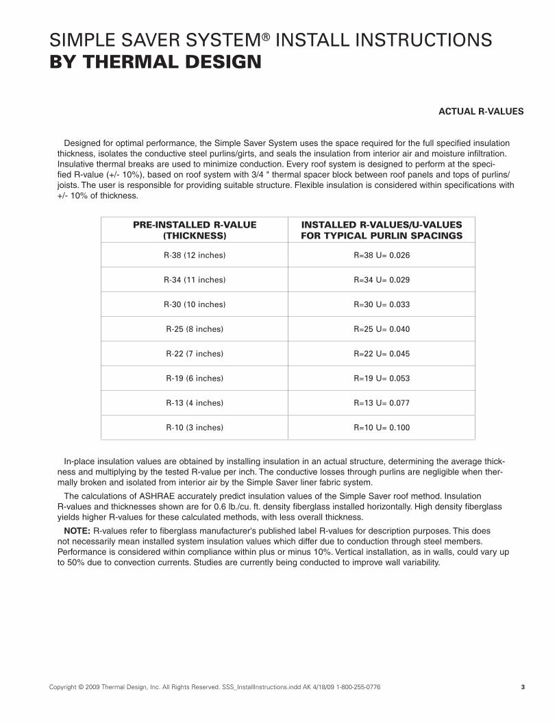
Designed for optimal performance, the Simple Saver System uses the space required for the full specified insulation thickness, isolates the conductive steel purlins/girts, and seals the insulation from interior air and moisture infiltration. Insulative thermal breaks are used to minimize conduction. Every roof system is designed to perform at the speci-fied R-value (+/- 10%), based on roof system with 3/4 " thermal spacer block between roof panels and tops of purlins/ joists. The user is responsible for providing suitable structure. Flexible insulation is considered within specifications with +/- 10% of thickness.
In-place insulation values are obtained by installing insulation in an actual structure, determining the average thick-ness and multiplying by the tested R-value per inch. The conductive losses through purlins are negligible when ther-mally broken and isolated from interior air by the Simple Saver liner fabric system.
The calculations of ASHRAE accurately predict insulation values of the Simple Saver roof method. Insulation R-values and thicknesses shown are for 0.6 lb./cu. ft. density fiberglass installed horizontally. High density fiberglass yields higher R-values for these calculated methods, with less overall thickness.
NOTE: R-values refer to fiberglass manufacturer's published label R-values for description purposes. This does not necessarily mean installed system insulation values which differ due to conduction through steel members. Performance is considered within compliance within plus or minus 10%. Vertical installation, as in walls, could vary up to 50% due to convection currents. Studies are currently being conducted to improve wall variability.
PRE-INSTALLED R-VALUE (THICKNESS)
INSTALLED R-VALUES/U-VALUES FOR TYPICAL PURLIN SPACINGS
R-38 (12 inches) R=38 U= 0.026
R-34 (11 inches) R=34 U= 0.029
R-30 (10 inches) R=30 U= 0.033
R-25 (8 inches) R=25 U= 0.040
R-22 (7 inches) R=22 U= 0.045
R-19 (6 inches) R=19 U= 0.053
R-13 (4 inches) R=13 U= 0.077
R-10 (3 inches) R=10 U= 0.100

4 Copyright © 2009 Thermal Design, Inc. All Rights Reserved. SSS_InstallInstructions.indd AK 4/18/09 1-800-255-0776
SIMPLE SAVER SYSTEM® INSTALL INSTRUCTIONSBY THERMAL DESIGN
Outdated insulation methods are often represented as the pre-installed R-values when they actually perform at far less. This table reveals the truth about the traditional over the purlin/girt method.
Based on NAIMA Formula: U=.012 + [0.255 / (.31Rf +t) ] (1-N / L) + (.198 + .065n) / L
Variables:Rf = The sum of inside and outside air films R-value of .78 used for all calculations.t = Pre-installed insulation thickness = see below.N = Number of purlins or girts in the L dimension = (L/spacing) +2.L = Dimension of the building section in linear feet = 100 foot width used.n = Fastener population per linear foot of purlin = one per linear foot used.U = Heat loss in BTU per square foot- hour- degree Fahrenheit.
Notes: In-place insulation values shown above are for white vinyl laminated installed in traditional over-the-purlin method based on published NAIMA Formula. The NAIMA Formula has been verified to be accurate in a study conducted by the BROOKHAVEN NATIONAL LABORATORY for the DEPARTMENT of ENERGY and NAIMA claims accuracy within 3%. In-place insulation values actually contained in a new building must be disclosed at the point of sale for the customer’s information and energy code compliance. Representation of insulation values greater than those indicated may be misrepresentation and in most states constitutes fraud.
Formula was derived from test data of non-reinforced vinyl faced insulation. Reinforced facings commonly in use are more resilient and are generally installed more tightly, resulting in greater compression of the insulation and less actual insulation performance than the above formula would indicate. Actual independent tests of the effects of reinforced facings on actual performance have not been made available to the general public. No valid representation of the in-place insulation performance with the reinforced facings can be made.
TIMA was an abbreviation for the Thermal Insulation Manufacturers Association, 1420 King St. #410, Alexandria, VA. 22314, (703) 684-0474. The formula for determining in-place R-value was published in the July issue of the Metal Construction News, in the letter to the editor. (Since this analysis was published, TIMA has changed its name to North American Insulation Manufacturers Association, or NAIMA.)
The Brookhaven National Laboratory, Upton, Long Island, NY 11973, issued a final report of the study entitled: Metal Building Study: Performance of Materials and Field Validation dated December 1987 by W. Loss. The study was supported by the United States Department of Energy. BNL 52134
This information is published as a public service by Thermal Design, Inc. Madison, NE. 68748, 402-454-6591. It may be reproduced for use in educating consumers and exposing misrepresentation of insulation values in metal building sales, specification compliance and energy code compliance. 11/91
ACTUAL R-VALUES OFOUTDATED INSULATION METHODS
PRE-INSTALLED R-VALUE
(THICKNESS)
INSTALLED R-VALUES AND U-VALUES*Add 1 to 2 R-values for standing seam roof with 1” standoff
Purlin/Girt Spacings and Percentage of Compression Loss
Five Ft./Pct. Loss Four Ft./Pct. Loss Three Ft./Pct. Loss Two Ft./Pct. Loss
R-19 (6 inches) R=10.05/47.2% R=9.04/52.5% R=7.74/59.3% R=6.02/68.4% U=0.10 U=0.11 U=0.13 U=0.17
R-16 (5 inches) R=9.46/40.9% R=8.60/46.2% R=7.45/53.4% R=5.89/63.2% U=0.11 U=0.12 U=0.13 U=0.17
R-13 (4 inches) R=8.72/32.9% R=8.01/38.4 R=7.05/45.8% R=5.70/56.2% U=0.11 U=0.12 U=0.14 U=0.18
R-10 (3 inches) R=7.73/22.7% R=7.22/27.8% R=6.50/35.0% R=5.41/45.9% U=0.13 U=0.14 U=0.15 U=0.18
R-6 (2 inches) R=6.37/106% R=6.08/101% R=5.65/94.1% R=4.95/82.5% U=0.16 U=0.16 U=0.18 U=0.20
Over the Purlin/Girt
Method (O-T-P)

Copyright © 2009 Thermal Design, Inc. All Rights Reserved. SSS_InstallInstructions.indd AK 4/18/09 1-800-255-0776 5
SIMPLE SAVER SYSTEM® INSTALL INSTRUCTIONSBY THERMAL DESIGN
NEW PRE-ENGINEERED BUILDING INSULATION INSTRUCTIONS WITH FREE
OSHA-ACCEPTED FALL PROTECTION
The Simple Saver System is a multi-purpose system that performs many functions with minor variations such as strap patterns, color, insulation thicknesses and types, layers, thermal break options, vented systems, etc. The system can also be used in many different types of structures, thus it is important to read the project instructions carefully and call Thermal Design (800-255-0776) or your distributor if there are any questions regarding installation procedures.
We have attempted to cover each type of installation in sufficient detail; however it is impossible to cover every cir-cumstance. Common sense and experience with the system will answer most questions. The basic concept of the Simple Saver System is:
1. Create a platform with tensioned steel straps (installed in the entire area to be insulated).2. Position and pull out the specially folded fabric liner on the strap platform and clamp it squarely in posi-
tion (generally a bay at a time).3. Fasten the steel strap platform supporting the fabric liner to the bottom of the purlin flanges with the self-
drilling washer head screws provided for that purpose.4. Seal the fabric liner perimeter edges to the abutting main frames and eave struts with the special con-
tact adhesive provided for that purpose. Syseal® Tape by Thermal Design will be used at any fabric liner splices. Inspect the fabric liner for any holes, patch and seal so that it is air tight. As an option, Syseal® Tape may also be used to seal the fabric liner to the bottom of the eave struts.
5. Unroll and position the insulation in the purlin cavity. It is recommended to thermally break the roof panels from the top of the purlins with a second layer of insulation and/or a thermal spacer block, typically pro-vided by the roof system manufacturer as a tested component.
Production rates for an R-30 two-layer roof insulation system are generally in the range of 150-200 sq. ft. per man-hour for the complete system installation in a typical pre-engineered metal building. Upwards to 300 sq. ft. per man-hour have been reported in larger buildings with experienced installers. The labor is approximately 1/2 strapping, 1/4 fabric liner and 1/4 insulation placement. Poor site conditions will affect the production rates. The fall protection feature can dramatically increase production rates by allowing workers to insulate and roof safely without being restrained by lanyards.
Installation training is available to contractors for a fee and is highly recommended. Video taped instructions are avail-able free of charge. Written instructions and project detail drawings take precedence over video instructions which are general in nature and intended to show technique.

6 Copyright © 2009 Thermal Design, Inc. All Rights Reserved. SSS_InstallInstructions.indd AK 4/18/09 1-800-255-0776
SIMPLE SAVER SYSTEM® INSTALL INSTRUCTIONSBY THERMAL DESIGN
Call (800) 255-0776 or your distributor for assistance if you have questions or if a stand-off bracket system is required to create added insulation space.
DEGREE OF DIFFICULTY AND PRODUCTION RATES
Installation of the Simple Saver System during the roof sheeting operation is much faster than retrofit installation, which is completely installed from the underside of the structure. The chart below gives ranges of production rates for use in estimating labor costs for installation.
There are many factors that affect production rates on every type of construction. Insulation systems are no excep-tion, therefore judgement is required in considering variables such as experience of the crew, available equipment, building height, weather likely during installation period, etc. The production rates below are ranges normally encoun-tered under average conditions with an experienced erection crew properly equipped to perform the work. We have timed many installations and find it fairly easy to achieve 150 square feet per man-hour on first time new construction installations. Experienced crews are known to achieve nearly 300 square feet per man-hour under ideal new construc-tion conditions. We suggest close observation of production rates to obtain experience rates for your own crew as being the best method of determining production rates.
*These rates are for typical metal buildings with eave height up to 30 feet. Add for additional height costs.
TOPSIDE INSTALLATION IN NEW BUILDINGS
Description Production Rates
Installing a single- or double-layer Simple Saver System during sheeting process (includes labor to install Quik-Stop™ Thermal Block in single-layer sys-tems)
Roof: 150-200 sq. ft./man-hour
Walls: 120-170 sq. ft./man-hour
Installation of thermal blocks alone to top side of structure located 5’ on-center
600 to 800 sq. ft./man-hour
Copyright © 2009 Thermal Design, Inc. All Rights Reserved. SSS_InstallInstructions.indd AK 4/18/09 1-800-255-0776 7
SIMPLE SAVER SYSTEM® INSTALL INSTRUCTIONSBY THERMAL DESIGN
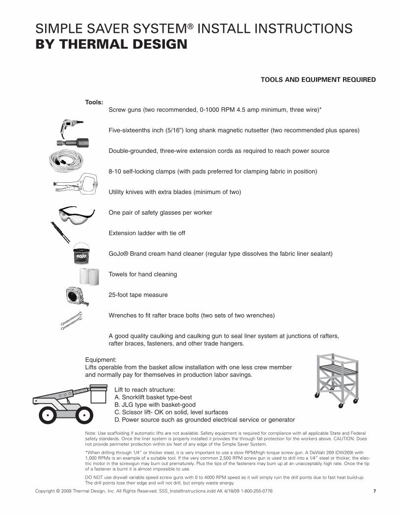
Tools:Screw guns (two recommended, 0-1000 RPM 4.5 amp minimum, three wire)*
Five-sixteenths inch (5/16”) long shank magnetic nutsetter (two recommended plus spares)
Double-grounded, three-wire extension cords as required to reach power source
8-10 self-locking clamps (with pads preferred for clamping fabric in position)
Utility knives with extra blades (minimum of two)
One pair of safety glasses per worker
Extension ladder with tie off
GoJo® Brand cream hand cleaner (regular type dissolves the fabric liner sealant)
Towels for hand cleaning
25-foot tape measure
Wrenches to fit rafter brace bolts (two sets of two wrenches)
A good quality caulking and caulking gun to seal liner system at junctions of rafters, rafter braces, fasteners, and other trade hangers.
Equipment:Lifts operable from the basket allow installation with one less crew member and normally pay for themselves in production labor savings.
Lift to reach structure: A. Snorklift basket type-bestB. JLG type with basket-goodC. Scissor lift- OK on solid, level surfacesD. Power source such as grounded electrical service or generator
Note: Use scaffolding if automatic lifts are not available. Safety equipment is required for compliance with all applicable State and Federal safety standards. Once the liner system is properly installed it provides the through fall protection for the workers above. CAUTION: Does not provide perimeter protection within six feet of any edge of the Simple Saver System.
*When drilling through 1/4” or thicker steel, it is very important to use a slow RPM/high torque screw gun. A DeWalt 269 (DW269) with 1,000 RPMs is an example of a suitable tool. If the very common 2,500 RPM screw gun is used to drill into a 1⁄4” steel or thicker, the elec-tric motor in the screwgun may burn out prematurely. Plus the tips of the fasteners may burn up at an unacceptably high rate. Once the tip of a fastener is burnt it is almost impossible to use.
DO NOT use drywall variable speed screw guns with 0 to 4000 RPM speed as it will simply ruin the drill points due to fast heat build-up. The drill points lose their edge and will not drill, but simply waste energy.
TOOLS AND EQUIPMENT REQUIRED
8 Copyright © 2009 Thermal Design, Inc. All Rights Reserved. SSS_InstallInstructions.indd AK 4/18/09 1-800-255-0776
SIMPLE SAVER SYSTEM® INSTALL INSTRUCTIONSBY THERMAL DESIGN
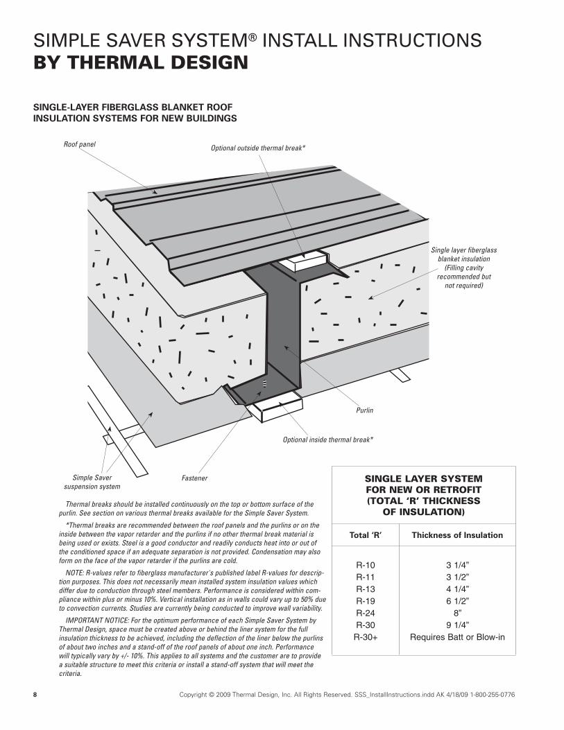
Thermal breaks should be installed continuously on the top or bottom surface of the purlin. See section on various thermal breaks available for the Simple Saver System.
*Thermal breaks are recommended between the roof panels and the purlins or on the inside between the vapor retarder and the purlins if no other thermal break material is being used or exists. Steel is a good conductor and readily conducts heat into or out of the conditioned space if an adequate separation is not provided. Condensation may also form on the face of the vapor retarder if the purlins are cold.
NOTE: R-values refer to fiberglass manufacturer's published label R-values for descrip-tion purposes. This does not necessarily mean installed system insulation values which differ due to conduction through steel members. Performance is considered within com-pliance within plus or minus 10%. Vertical installation as in walls could vary up to 50% due to convection currents. Studies are currently being conducted to improve wall variability.
IMPORTANT NOTICE: For the optimum performance of each Simple Saver System by Thermal Design, space must be created above or behind the liner system for the full insulation thickness to be achieved, including the deflection of the liner below the purlins of about two inches and a stand-off of the roof panels of about one inch. Performance will typically vary by +/- 10%. This applies to all systems and the customer are to provide a suitable structure to meet this criteria or install a stand-off system that will meet the criteria.
Optional outside thermal break*Roof panel
Single layer fiberglass blanket insulation
(Filling cavity recommended but
not required)
Purlin
Optional inside thermal break*
Simple Saver suspension system
Fastener
SINGLE-LAYER FIBERGLASS BLANKET ROOF INSULATION SYSTEMS FOR NEW BUILDINGS
SINGLE LAYER SYSTEM FOR NEW OR RETROFIT(TOTAL ‘R’ THICKNESS
OF INSULATION)
Total ‘R’ Thickness of Insulation
R-10R-11R-13R-19R-24R-30
R-30+
3 1/4”3 1/2”4 1/4”6 1/2”
8”9 1/4”
Requires Batt or Blow-in
© Thermal Design, Inc.

Copyright © 2009 Thermal Design, Inc. All Rights Reserved. SSS_InstallInstructions.indd AK 4/18/09 1-800-255-0776 9
SIMPLE SAVER SYSTEM® INSTALL INSTRUCTIONSBY THERMAL DESIGN
Roof panel
Purlin
Simple Saver suspension system
Fastener
Two layers of fiberglass
blanket insulation
DOUBLE-LAYER FIBERGLASS BLANKET INSULATION SYSTEMS FOR NEW BUILDINGS
Optional topside thermal blocks may be used in two layer systems to reduce conduction and create more space. Bottomside thermal breaks may be utilized for the same pur-pose.
NOTE: R-values refer to fiberglass manufacturer's pub-lished label R-values for description purposes. This does not necessarily mean installed system insulation values which differ due to conduction through steel members. Performance is considered within compliance within plus or minus 10%. Vertical installation as in walls could vary up to 50% due to convection currents. Studies are currently being conducted to improve wall variability.
IMPORTANT NOTICE: For the optimum performance of each Simple Saver System by Thermal Design, space must be cre-ated above or behind the liner system for the full insulation thickness to be achieved, including the deflection of the liner below the girts of about two inches and a stand-off of the roof panels of about one inch. Performance will typically vary by +/- 10%. This applies to all systems and the customer are to provide a suitable structure to meet this criteria or install a stand-off system that will meet the criteria.
DOUBLE-LAYER SIMPLE SAVER SYSTEM FOR NEW METAL BUILDINGS
First Layer Second Layer Total R-value
R-10 = 3 1/4”R-19 = 6 1/2”R-19 = 6 1/2”R-19 = 6 1/2”R-30 = 9 1/4”R-30 = 9 1/4”
R-10 = 3 1/4”R-10 = 3 1/4”R-13 = 4 1/4”R-19 = 6 1/2”R-10 = 3 1/4”R-13 = 4 1/4”
R-20R-29R-32R-38R-40R-43
Note: Higher R-values and other combinations available
© Thermal Design, Inc.

10 Copyright © 2009 Thermal Design, Inc. All Rights Reserved. SSS_InstallInstructions.indd AK 4/18/09 1-800-255-0776
SIMPLE SAVER SYSTEM® INSTALL INSTRUCTIONSBY THERMAL DESIGN
Rigid foam insulation board (third party)Roof panel
Purlin
Simple Saver suspension system*
Fastener
Single layer fiberglass blanket insulation
Optional bottomside thermal blocks may be used in a single layer system to reduce conduction and create more space for additional insulation thickness. This would allow higher R-values to be achieved.
NOTE: R-values refer to fiberglass manufacturer's pub-lished label R-values for description purposes. This does not necessarily mean installed system insulation values which differ due to conduction through steel members. Performance is considered within compliance within plus or minus 10%. Vertical installation as in walls could vary up to 50% due to convection currents. Studies are cur-rently being conducted to improve wall variability.
IMPORTANT NOTICE: For the optimum performance of each Simple Saver System by Thermal Design, space must be created above or behind the liner system for the full insulation thickness to be achieved, including the deflec-tion of the liner below the purlins of about two inches and a stand-off of the roof panels of about one inch. Performance will typically vary by +/- 10%. This applies to all systems and the customer are to provide a suitable structure to meet this criteria or install a stand-off system that will meet the criteria.
SINGLE-LAYER FIBERGLASS BLANKET INSULATION SYSTEMS WITH RIGID FOAM INSULATION BOARD BETWEEN ROOF SHEET AND PURLIN
SINGLE-LAYER SIMPLE SAVER SYSTEM WITH 1” RIGID FOAM INSULATION BOARD
FOR NEW METAL BUILDINGS
Thickness of Insulation 1” Rigid Foam Total ‘R’
R-10 = 3 1⁄4”R-11 = 3 1/2”R-13 = 4 1⁄4”R-19 = 6 1/2”
R-24 = 8”R-30 = 9 1⁄4”
R-8R-8R-8R-8R-8R-8
R-18R-19R-21R-27R-32R-38
© Thermal Design, Inc.

Copyright © 2009 Thermal Design, Inc. All Rights Reserved. SSS_InstallInstructions.indd AK 4/18/09 1-800-255-0776 11
SIMPLE SAVER SYSTEM® INSTALL INSTRUCTIONSBY THERMAL DESIGN
Step 1. To begin the installation of the strap platform, open the package containing the packing list and project drawings. Check to be sure all materials are there and that they are not damaged. If something is missing or damaged, contact Thermal Design at (800) 255-0776 or your distributor. Any damages to materials from shipping must have claims filed directly with the carrier. Do not install damaged materials. Carefully review the project drawings and written instructions.
Step 2. Assemble the strap dispenser on the ground or floor at one end of the building. Cut a number of steel straps the length of the building plus two feet. Using a lift, feed several straps over the building rafters from one end of the building to the other. (Tip: Bend a sharp hook in the strap about four inches from the end to hook over the top rafter flanges to aid in installation.) Two straps per five foot purlin space are required. See the project drawings for exact spacings. Straps for two or three purlin spaces may be pulled in on each lengthwise pass to save time. (Tip: Always keep finished side down and avoid twisting the straps.)
Step 3. Pull all the longitudinal straps over the rafters with the finished side (normally white) down and hook them on the far end rafter. Once a number of straps are pulled into position, one crew person fastens the far end of each strap with two self-drilling washer head fasteners to the top of the far end rafter. Complete this process with all straps. Required: Maintain fasteners a minimum of 3” apart and centered on the strap when fasten-ing; also keep the fasteners 3” from the end of strap. Use the fine thread washer-head self-drilling screws for fastening to thicker steel or rake angle. Steel over 3/8” thick may require pre-drilling of holes with a drill bit (not provided).
Step 4. Hook the other end of the lengthwise straps to the near end rafter and fasten as follows: a) Drill a fastener partially into the rafter to start a hole, being careful to maintain proper spacing as shown in the drawings. b) Pull each strap tight by hand and fully drill a fastener through the strap about 3/8” to 1/2” short of the started hole. Drill the fastener all the way into the strap, then angle the fastener tip into the started hole and screw it in (see Figure 1). This method will tension the lengthwise strap as it screws in to the hole. c) Then install a second fastener through the same strap 3” away from the first and 3" away from the end of the strap.
Step 5. Repeat this process until all the longitudinal straps are installed.
INSTALLATION OF GRID STRAP PLATFORM
12 Copyright © 2009 Thermal Design, Inc. All Rights Reserved. SSS_InstallInstructions.indd AK 4/18/09 1-800-255-0776
SIMPLE SAVER SYSTEM® INSTALL INSTRUCTIONSBY THERMAL DESIGN
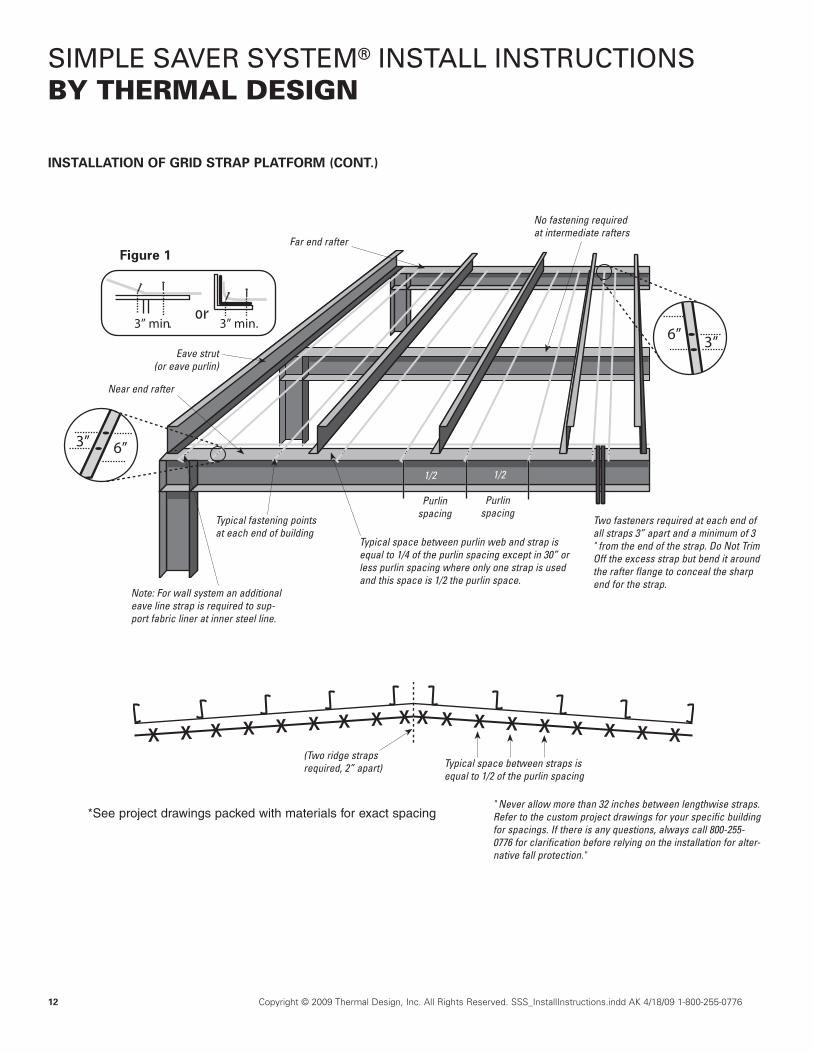
3”6”
3” 6”
3” min.3” min.
*See project drawings packed with materials for exact spacing
(Two ridge straps required, 2” apart)
Far end rafter
Near end rafter
Eave strut(or eave purlin)
Note: For wall system an additional eave line strap is required to sup-port fabric liner at inner steel line.
Typical space between purlin web and strap is equal to 1/4 of the purlin spacing except in 30” or less purlin spacing where only one strap is used and this space is 1/2 the purlin space.
Typical fastening points at each end of building
Two fasteners required at each end of all straps 3” apart and a minimum of 3 " from the end of the strap. Do Not Trim Off the excess strap but bend it around the rafter flange to conceal the sharp end for the strap.
1/2 1/2
Figure 1
No fastening required at intermediate rafters
or
Purlin spacing
Purlin spacing
Typical space between straps is equal to 1/2 of the purlin spacing
" Never allow more than 32 inches between lengthwise straps. Refer to the custom project drawings for your specific building for spacings. If there is any questions, always call 800-255-0776 for clarification before relying on the installation for alter-native fall protection."
INSTALLATION OF GRID STRAP PLATFORM (CONT.)
© Thermal Design, Inc.
Copyright © 2009 Thermal Design, Inc. All Rights Reserved. SSS_InstallInstructions.indd AK 4/18/09 1-800-255-0776 13
SIMPLE SAVER SYSTEM® INSTALL INSTRUCTIONSBY THERMAL DESIGN
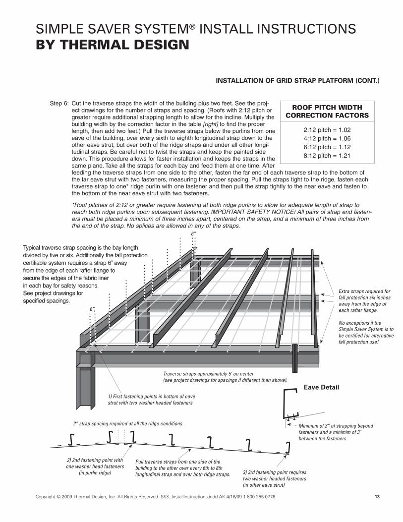
Pull traverse straps from one side of the building to the other over every 6th to 8th longitudinal strap and over both ridge straps.
2) 2nd fastening point with one washer head fasteners
(in purlin ridge) 3) 3rd fastening point requires two washer headed fasteners(in other eave strut)
2” strap spacing required at all the ridge conditions.
Extra straps required for fall protection six inches away from the edge of each rafter flange.
No exceptions if the Simple Saver System is to be certified for alternative fall protection use!
INSTALLATION OF GRID STRAP PLATFORM (CONT.)
Step 6: Cut the traverse straps the width of the building plus two feet. See the proj-ect drawings for the number of straps and spacing. (Roofs with 2:12 pitch or greater require additional strapping length to allow for the incline. Multiply the building width by the correction factor in the table [right] to find the proper length, then add two feet.) Pull the traverse straps below the purlins from one eave of the building, over every sixth to eighth longitudinal strap down to the other eave strut, but over both of the ridge straps and under all other longi-tudinal straps. Be careful not to twist the straps and keep the painted side down. This procedure allows for faster installation and keeps the straps in the same plane. Take all the straps for each bay and feed them at one time. After feeding the traverse straps from one side to the other, fasten the far end of each traverse strap to the bottom of the far eave strut with two fasteners, measuring the proper spacing. Pull the straps tight to the ridge, fasten each traverse strap to one* ridge purlin with one fastener and then pull the strap tightly to the near eave and fasten to the bottom of the near eave strut with two fasteners.
*Roof pitches of 2:12 or greater require fastening at both ridge purlins to allow for adequate length of strap to reach both ridge purlins upon subsequent fastening. IMPORTANT SAFETY NOTICE! All pairs of strap end fasten-ers must be placed a minimum of three inches apart, centered on the strap, and a minimum of three inches from the end of the strap. No splices are allowed in any of the straps.
Typical traverse strap spacing is the bay length divided by five or six. Additionally the fall protection certifiable system requires a strap 6” away from the edge of each rafter flange to secure the edges of the fabric liner in each bay for safety reasons. See project drawings for specified spacings.
1) First fastening points in bottom of eave strut with two washer headed fasteners
Traverse straps approximately 5’ on center (see project drawings for spacings if different than above).
6”
6”
ROOF PITCH WIDTH CORRECTION FACTORS
2:12 pitch = 1.024:12 pitch = 1.066:12 pitch = 1.128:12 pitch = 1.21
Minimum of 3” of strapping beyond fasteners and a minimim of 3" between the fasteners.
Eave Detail
© Thermal Design, Inc.

14 Copyright © 2009 Thermal Design, Inc. All Rights Reserved. SSS_InstallInstructions.indd AK 4/18/09 1-800-255-0776
SIMPLE SAVER SYSTEM® INSTALL INSTRUCTIONSBY THERMAL DESIGN
Bay with fabric shown installed
Self-locking clamps holding fabric in position
Pleat folded fabric liner
Position specially folded fabric liner between two purlins being careful to normally put white side down Eaveline strap
(wall system only)
Building Rafter
Fabric liner pulled over strap platform
under purlins
A
Step 1: Select the package clearly marked with the specified piece of fabric liner, which will be marked to match the cus-tom project drawing layout, and remove the protective packaging. Unroll the factory-folded fabric liner on the ten-sioned strap platform from one rafter to another. Position the fabric between any two purlins, normally at the ridge or eave. Be sure the correct color side will be down since the fabric can be reversed and be different colors.
Step 2: Pull the bottom edge of the fabric liner at least eight inches beyond the outside corner (A) of the eave strut and clamp one corner securely in position above the near rafter with a self-locking clamp. Then pull the other corner (B) above the other rafter plus eight inches, while keeping the fabric tight and square with the eave strut. Clamp the fabric in that position. Be sure to allow for the extra eight inches of fabric. Important! Keep the fabric square with the eave struts and centered on the bay. This will minimize potential wrin-kles. Due to the flexible nature of the fabric and the large sizes used, some wrinkles are inevitable. See project drawings for each bay’s fabric sizes.
Fabric liner
Position fabric over- lapping the top of the rafter flange to a point within 1” from the opposite rafter edge
Self-locking clamp holding fabric in place
Top rafter flange
Fabric
Arrows show direction fabric is pulled to unfold
Important!Keep fabric square with eave!
Platform of straps
Self-locking clamp
Eave Detail:
Minimum of 8” of extra fabric beyond the outside corner of the eave strut and securely clamp the fabric in the position. Always keep the fabric edge square with the eave line by keeping the dimensions of the vertical fabric edge eight inches up from the lower corner of the eave strut as shown. Clamp the fabric to in that position pending permanent fastening.
8”
B
Recommended type of self-locking clamps
A
A
FABRIC LINER INSTALLATION (APPROX. 600 SQ. FT./MAN-HOUR)
© Thermal Design, Inc.
Eave strut (or eave purlin)
Required extra fabric edge tab for certifiable fall protection systems.
Required extra fabric edge tab for certifiable fall protection systems.
8"
8"
Copyright © 2009 Thermal Design, Inc. All Rights Reserved. SSS_InstallInstructions.indd AK 4/18/09 1-800-255-0776 15
SIMPLE SAVER SYSTEM® INSTALL INSTRUCTIONSBY THERMAL DESIGN
FABRIC LINER INSTALLATION (CONT.)
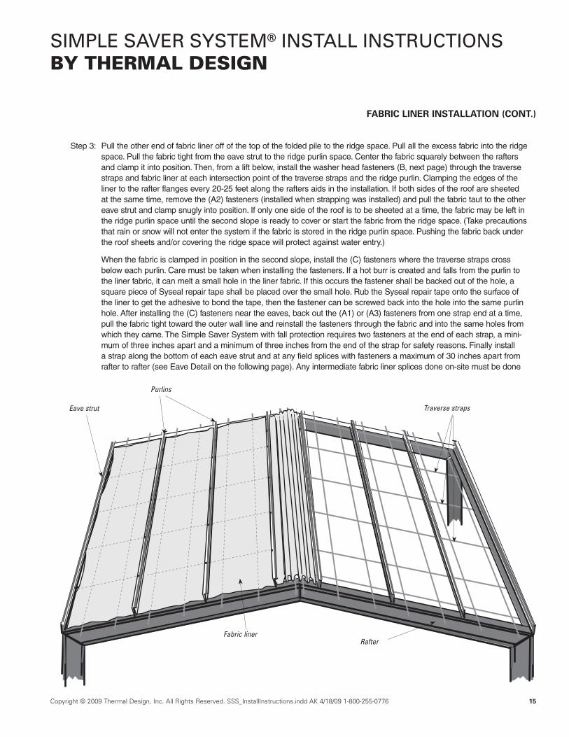
Step 3: Pull the other end of fabric liner off of the top of the folded pile to the ridge space. Pull all the excess fabric into the ridge space. Pull the fabric tight from the eave strut to the ridge purlin space. Center the fabric squarely between the rafters and clamp it into position. Then, from a lift below, install the washer head fasteners (B, next page) through the traverse straps and fabric liner at each intersection point of the traverse straps and the ridge purlin. Clamping the edges of the liner to the rafter flanges every 20-25 feet along the rafters aids in the installation. If both sides of the roof are sheeted at the same time, remove the (A2) fasteners (installed when strapping was installed) and pull the fabric taut to the other eave strut and clamp snugly into position. If only one side of the roof is to be sheeted at a time, the fabric may be left in the ridge purlin space until the second slope is ready to cover or start the fabric from the ridge space. (Take precautions that rain or snow will not enter the system if the fabric is stored in the ridge purlin space. Pushing the fabric back under the roof sheets and/or covering the ridge space will protect against water entry.)
When the fabric is clamped in position in the second slope, install the (C) fasteners where the traverse straps cross below each purlin. Care must be taken when installing the fasteners. If a hot burr is created and falls from the purlin to the liner fabric, it can melt a small hole in the liner fabric. If this occurs the fastener shall be backed out of the hole, a square piece of Syseal repair tape shall be placed over the small hole. Rub the Syseal repair tape onto the surface of the liner to get the adhesive to bond the tape, then the fastener can be screwed back into the hole into the same purlin hole. After installing the (C) fasteners near the eaves, back out the (A1) or (A3) fasteners from one strap end at a time, pull the fabric tight toward the outer wall line and reinstall the fasteners through the fabric and into the same holes from which they came. The Simple Saver System with fall protection requires two fasteners at the end of each strap, a mini-mum of three inches apart and a minimum of three inches from the end of the strap for safety reasons. Finally install a strap along the bottom of each eave strut and at any field splices with fasteners a maximum of 30 inches apart from rafter to rafter (see Eave Detail on the following page). Any intermediate fabric liner splices done on-site must be done
Traverse strapsEave strut
Purlins
Fabric linerRafter
© T
hermal D
esign, Inc.

16 Copyright © 2009 Thermal Design, Inc. All Rights Reserved. SSS_InstallInstructions.indd AK 4/18/09 1-800-255-0776
SIMPLE SAVER SYSTEM® INSTALL INSTRUCTIONSBY THERMAL DESIGN
FABRIC LINER INSTALLATION (CONT.)
�1� � � � � �
� �2�3
Typical fastener designation Strap platform
Fabric liner
Splice Detail at a Purlin
Minimum of 6” of fabric beyond fastening point
Minimum of 6” of fabric beyond fastening point
Adhered to purlin on uphill side
Tape sealant on edges*
Double ridge straps 2” apart
Install strap along any splices in fabric with fasteners a maximum of thirty inches apart through this strap from rafter to rafter.Fasteners on splices at
each strap end and amaximum of 30”on center
B
Edge strap fastened maximum of 30” on center along bottom of eave strut
Minimum of 3” of strapping beyond fastener1
Fabric liner must be sealed to eave strut*
Minimum of 6” of fabric beyond fastening point
Standard Eave Detail
A
Special Eave Detail
Eave strut
Fabric liner Roof strap
4" x 2" Angle(14-16 GA)
Wall girt8"
Strap fastener
Wall fabric liner
Vertical strap
For use if a more finished look is desired where the roof and wall systems adjoin each other. Recommended when roof and wall systems are different colors.
*Tape sealant must run continuous from along the edge of liner fabric from rafter to rafter to seal against any air infiltration.
*Make sure all holes in the eave strut are covered and sealing of the fabric is done between any hole and the wall of the building.
Copyright © 2009 Thermal Design, Inc. All Rights Reserved. SSS_InstallInstructions.indd AK 4/18/09 1-800-255-0776 17
SIMPLE SAVER SYSTEM® INSTALL INSTRUCTIONSBY THERMAL DESIGN
FABRIC LINER INSTALLATION (CONT.)
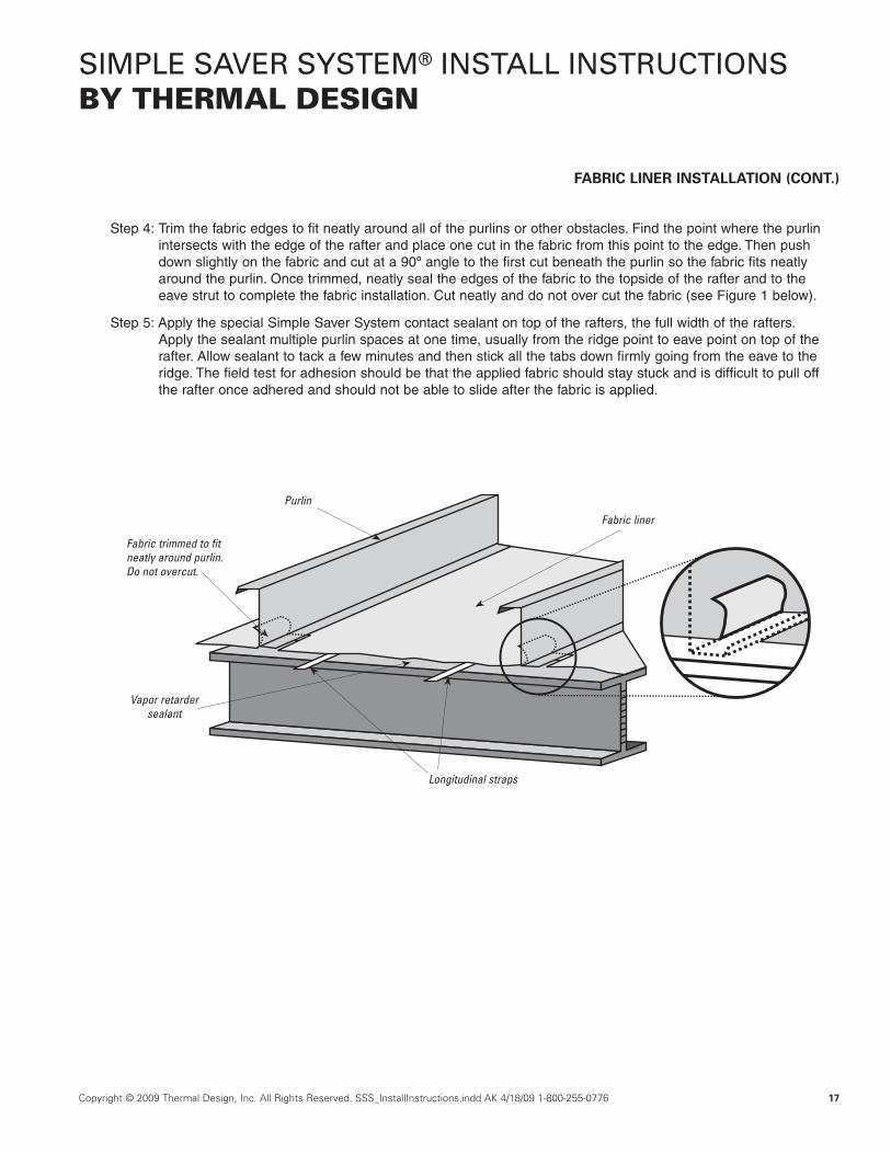
Step 4: Trim the fabric edges to fit neatly around all of the purlins or other obstacles. Find the point where the purlin intersects with the edge of the rafter and place one cut in the fabric from this point to the edge. Then push down slightly on the fabric and cut at a 90º angle to the first cut beneath the purlin so the fabric fits neatly around the purlin. Once trimmed, neatly seal the edges of the fabric to the topside of the rafter and to the eave strut to complete the fabric installation. Cut neatly and do not over cut the fabric (see Figure 1 below).
Step 5: Apply the special Simple Saver System contact sealant on top of the rafters, the full width of the rafters. Apply the sealant multiple purlin spaces at one time, usually from the ridge point to eave point on top of the rafter. Allow sealant to tack a few minutes and then stick all the tabs down firmly going from the eave to the ridge. The field test for adhesion should be that the applied fabric should stay stuck and is difficult to pull off the rafter once adhered and should not be able to slide after the fabric is applied.
Purlin
Fabric liner
Fabric trimmed to fit neatly around purlin. Do not overcut.
Vapor retarder sealant
Longitudinal straps
© Thermal Design, Inc.
18 Copyright © 2009 Thermal Design, Inc. All Rights Reserved. SSS_InstallInstructions.indd AK 4/18/09 1-800-255-0776
SIMPLE SAVER SYSTEM® INSTALL INSTRUCTIONSBY THERMAL DESIGN
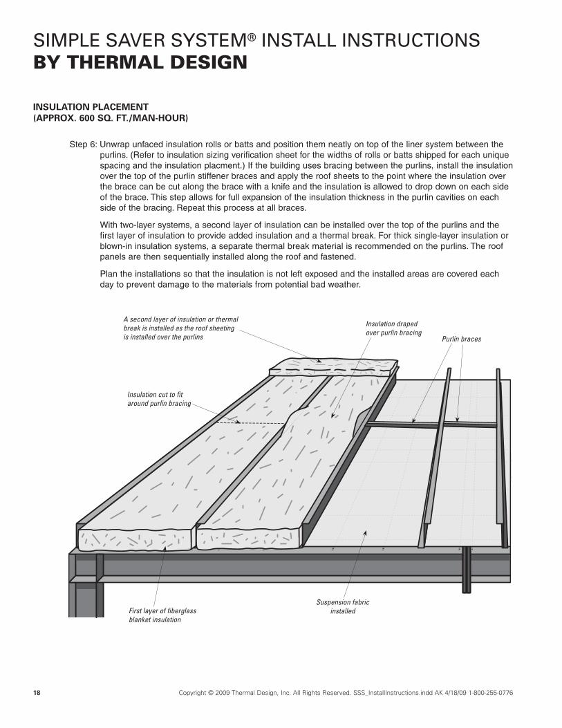
INSULATION PLACEMENT (APPROX. 600 SQ. FT./MAN-HOUR)
Step 6: Unwrap unfaced insulation rolls or batts and position them neatly on top of the liner system between the purlins. (Refer to insulation sizing verification sheet for the widths of rolls or batts shipped for each unique spacing and the insulation placment.) If the building uses bracing between the purlins, install the insulation over the top of the purlin stiffener braces and apply the roof sheets to the point where the insulation over the brace can be cut along the brace with a knife and the insulation is allowed to drop down on each side of the brace. This step allows for full expansion of the insulation thickness in the purlin cavities on each side of the bracing. Repeat this process at all braces.
With two-layer systems, a second layer of insulation can be installed over the top of the purlins and the first layer of insulation to provide added insulation and a thermal break. For thick single-layer insulation or blown-in insulation systems, a separate thermal break material is recommended on the purlins. The roof panels are then sequentially installed along the roof and fastened.
Plan the installations so that the insulation is not left exposed and the installed areas are covered each day to prevent damage to the materials from potential bad weather.
A second layer of insulation or thermal break is installed as the roof sheeting is installed over the purlins
First layer of fiberglass blanket insulation
Suspension fabric installed
Insulation cut to fit around purlin bracing
Insulation draped over purlin bracing
Purlin braces

Copyright © 2009 Thermal Design, Inc. All Rights Reserved. SSS_InstallInstructions.indd AK 4/18/09 1-800-255-0776 19
SIMPLE SAVER SYSTEM® INSTALL INSTRUCTIONSBY THERMAL DESIGN
Figure 2Neatly caulk along rafter flanges
Caulk gun
Step 7: In high humidity applications, it is recommended that the junction of the liner fabric along the rafter flanges and the fabric be caulked with a clear siliconized acrylic latex caulk (caulking is not provided with the system). See Figure 2 where it has been trimmed to fit around purlins, rafters, braces, etc. It is recom-mended that the installation be inspected and any cuts, pinholes or other such breaches in the fabric liner be sealed with caulking, tape or a flashing upon installation completion (see Figure 2). If no Simple Saver wall system will be installed, trim off any excess fabric and steel strapping at the eave lines, however not before all fall protection use of the Simple Saver liner fabric in the roof is finished.
Desired insulation position
Purlin stiffener brace Purlin
Knife
Former insulation position
Purlin
Purlin
Cut in insulation roll
INSULATION PLACEMENT (CONT.) AND CAULKING CUTS AND PENETRATIONS
20 Copyright © 2009 Thermal Design, Inc. All Rights Reserved. SSS_InstallInstructions.indd AK 4/18/09 1-800-255-0776
SIMPLE SAVER SYSTEM® INSTALL INSTRUCTIONSBY THERMAL DESIGN
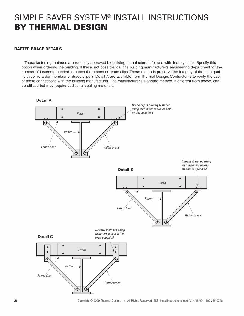
RAFTER BRACE DETAILS
These fastening methods are routinely approved by building manufacturers for use with liner systems. Specify this option when ordering the building. If this is not possible, call the building manufacturer’s engineering department for the number of fasteners needed to attach the braces or brace clips. These methods preserve the integrity of the high qual-ity vapor retarder membrane. Brace clips in Detail A are available from Thermal Design. Contractor is to verify the use of these connections with the building manufacturer. The manufacturer’s standard method, if different from above, can be utilized but may require additional sealing materials.
Detail B
Detail C
Rafter brace
Rafter
Purlin
Directly fastened using four fasteners unless otherwise specified
Fabric liner
Rafter brace
Rafter
Purlin
Directly fastened using fasteners unless other-wise specified
Fabric liner
Detail A
Rafter brace
Rafter
Brace clip is directly fastened using four fasteners unless oth-erwise specified
Fabric liner
Purlin
© Thermal Design, Inc.
© Thermal Design, Inc.

Copyright © 2009 Thermal Design, Inc. All Rights Reserved. SSS_InstallInstructions.indd AK 4/18/09 1-800-255-0776 21
SIMPLE SAVER SYSTEM® INSTALL INSTRUCTIONSBY THERMAL DESIGN
Brace clips are 14 GA. (stock item)
Material available in other gauges and in other lengths by special order. Standard finish color for brace clips is white. Drawings not to scale.
3”
1” 3”
2 1/2”
4”
3/4” 3/4”
1/4” Diameter holes (4)
2”
5/8”
5/8”
5/8” diameter hole
3/4”2 1/2”3/4”
RECOMMENDED MINIMUM BRACE CLIP DETAILS (CONSULT YOUR BUILDING MANUFACTURER)
© Thermal Design, Inc.
22 Copyright © 2009 Thermal Design, Inc. All Rights Reserved. SSS_InstallInstructions.indd AK 4/18/09 1-800-255-0776
SIMPLE SAVER SYSTEM® INSTALL INSTRUCTIONSBY THERMAL DESIGN
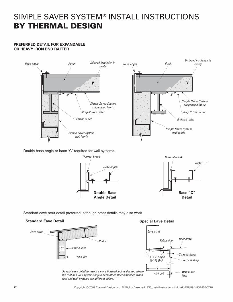
PREFERRED DETAIL FOR EXPANDABLE OR HEAVY IRON END RAFTER
Rake angle
Simple Saver System suspension fabric
Strap 6" from rafterStrap 6" from rafter
6"
Endwall rafter
Simple Saver System wall fabric
Simple Saver System wall fabric
Double base angle or base “C” required for wall systems.
Thermal break
Base angles
Double Base Angle Detail
Thermal break
Base “C”
Base “C” Detail
Standard eave strut detail preferred, although other details may also work.
Purlin Unfaced insulation in cavity
Endwall rafter
Rake angle PurlinUnfaced insulation in
cavity
Simple Saver System suspension fabric
8”
Eave strut
Purlin
Fabric liner
Wall girt
Special Eave Detail
Eave strut
Fabric liner Roof strap
4" x 2" Angle(14-16 GA)
Wall girt8"
Strap fastener
Wall fabric liner
Vertical strap
Special eave detail for use if a more finished look is desired where the roof and wall systems adjoin each other. Recommended when roof and wall systems are different colors.
Standard Eave Detail
© Thermal Design, Inc. © Thermal Design, Inc.
6"

Copyright © 2009 Thermal Design, Inc. All Rights Reserved. SSS_InstallInstructions.indd AK 4/18/09 1-800-255-0776 23
SIMPLE SAVER SYSTEM® INSTALL INSTRUCTIONSBY THERMAL DESIGN
Wall sheetingEnd wall frame
Seal edge of fabric to end wall frame
Simple Saver System suspension fabric
Unfaced insulation in cavity
Rake angle Purlin
Seal separate piece of suspension fabric two ft. or larger to end wall
and rake angle
Wall sheeting End wall “C” rafter
Seal edge of fabric to end “C”rafter
Unfaced insulation in cavity
Fasten longitudinal strap to end wall rafter with two self-drilling
fasteners, three in. apart
Seal suspension fabric to end wall and rake
angle
Min. 3" strap beyond last
fastener
Expandable End Wall or Heavy Iron Rafter
Traverse strapfastened to purlin
Non-Expandable End Wall
Optional thermal break
Optional thermal break
INSTALLATION OF TWO-FOOT WIDE (OR SIMILAR) INSET FABRIC LINER BETWEEN ENDWALL FRAME AND RAKE ANGLE
© Thermal Design, Inc.
© Thermal Design, Inc.
Min. 3" strap beyond last
fastener
Fasten longitudinal strap to end wall rafter with two self-drilling
fasteners, three in. apart

24 Copyright © 2009 Thermal Design, Inc. All Rights Reserved. SSS_InstallInstructions.indd AK 4/18/09 1-800-255-0776
SIMPLE SAVER SYSTEM® INSTALL INSTRUCTIONSBY THERMAL DESIGN
SNAP-R® THERMAL BLOCK AND QUICK-STOP™ TAPE THERMAL BREAK
To install, snap on with a twist motion then slide along the purlins. They won’t blow away!
Use on the inside, outside or both
Standard dimensions available in 3/8” or 1” thickness and 24” lengths. Other sizes are special order.
1”
3/8”
3/8”
3/8”
3/8”
3/8”
The adhesive foam tape thermal break adheres to the purlins and/or girts and won't blow away while sheeting is being applied. The Quick-Stop™ thermal break tape provides a thermal break between the conductive metal sheeting and purlins or girts. Use on the topside, bottomside or both.

Copyright © 2009 Thermal Design, Inc. All Rights Reserved. SSS_InstallInstructions.indd AK 4/18/09 1-800-255-0776 25
SIMPLE SAVER SYSTEM® INSTALL INSTRUCTIONSBY THERMAL DESIGN
Common Hanging Methods
Simple Fastener Hole Strap Channel Strut Angle Hanger Threaded Plate Hanger Threaded Hanger Bar Joist Hanger
COMMON FASTENERS, HANGERS AND METHODS
Pipe Style Hanger
Self-Drilling Fasteners
Lag Fastener
Wood Fastener
Double-threaded Nut for Threaded Rod
Wood, Steel or Masonry
Threaded ends for Threaded Rods or
Mounting Bolts
Cully "Jiffy Screw" (Acoustical Eye "Tek" Screw)
© Thermal Design, Inc.
© Thermal Design, Inc.

26 Copyright © 2009 Thermal Design, Inc. All Rights Reserved. SSS_InstallInstructions.indd AK 4/18/09 1-800-255-0776
SIMPLE SAVER SYSTEM® INSTALL INSTRUCTIONSBY THERMAL DESIGN
Third-party fasteners are available from Thermal Design for distinct fastening methods. These products specialize in hanging ductwork, pipes, and other items from ceiling without having to cut large holes in the vapor retarder. Ask your salesperson about these and other suspension methods. (Check with your building manufacturer for all applications to meet building requirements. Be sure to fasten optional angle irons or side beam connectors before installing the fabric.)
SPECIFIC THIRD-PARTY HANGERS AND METHODS
Steel Sammy: self-drilling and self-tapping double-threaded nut for threaded rods. (DSTR)
Purlin Purlin
Purlin Threaded Rod
Threaded RodThreaded Rod
HangerMate
Side Beam Connector
Angle Attached to Purlin
Steel Sidewinder: Self-drilling and self-tapping double-threaded nut for threaded rods. Install Sidewinder before insulation system. (SWDR)
Sammy X-Press™ before fastening
Sammy X-Press™
Purlin
Threaded Rod
Washer Washer
Washer
Lock nut
Copyright © 2009 Thermal Design, Inc.PO Box 468, Madison, NE 68748
All rights reserved, including the right of reproduction in whole or in parts in any form. Simple Saver System® is a registered trademark of Thermal Design, Inc.Syseal®, Fast-R™ and Snap-R® are trademarks of Thermal Design, Inc.SSS_InstallInstructions.indd AK
Thermal Performance Guarantee: Thermal Design, Inc. will guarantee to the building owner/user that the thermal performance of a Simple Saver System will perform at the average purchased insulation level, plus or minus 10%, when properly installed at the prescribed thickness and sealed against air and water vapor infiltration. Thermal Design shall, at its option, correct any deficien-cies of thermal performance or credit to the owner/user the percentage of the insulation material cost equal to the percentage of any deficiency if a valid claim is filed within one year after installation.
Ten-Year Limited Material Warranty: The Simple Saver System is warranted against manufacturing defects in materials that are provided by Thermal Design that may become evident within ten years after delivery. This warranty is spe-cifically limited to providing materials for replacement of specific areas affected and only to the extent that the defect is adversely affecting performance, and does not include any expense to remove or install materials, site workmanship or damages that may be caused by defective materials, installation, damage to materials caused by others, abuse and misuse of the product, or design. The warranty is pro-rated (e.g. 100% of the material replacement cost during the first year, 90% during the second year, 80% during the third year, etc.). Labor is typically covered by contractor's warranty for at least one year after installation completion. Thermal Design shall make the final decision as to the validity and extent of any defect claim. Valid claims will be limited to the pro-rated value of the purchased materials cost or the cost value thereof, as determined by Ther-mal Design. Any claims should be submitted in writing by US Mail to Thermal Design, Inc., P.O. Box 468, Madison, NE, 68748. There are no other expressed or implied warranties that extend beyond these limitations and these are a con-dition of the sale of these goods. The company shall not be held responsible for consequential, liquidated or other damages under any theory of law.
Notices: All customers will be charged Nebraska sales tax on all products unless sales and use tax certificates are provided. Point of sale and venue for all claims shall be Madison County, Nebraska. Any material not specifically included on a quotation is excluded although additional materials may be provided solely at the discretion of Thermal Design.
Unauthorized making, using or selling of this patented technology or trade-marks or service marks shall be each subject to a minimum royalty of ten dollars per square foot of surface insulated from such unauthorized acts. Sellers of any component with the knowledge or intent that such component is to be used to evade the purchase of legitimate materials from authorized sources shall be held liable as contributory infringes and otherwise as lawful. All costs of collection, including legal fees and costs, shall be sought as damages for unauthorized infringement.
The EnergyCraft units are factory run tested. Minor adjustment may have to be made on site. Installation of these appliances and framing kits normally do not require a license. Installation of gas piping and electric power to the appli-ance receptacles should be done by a qualified licensed installer. See Goodman manufacturing warranty documents for limitations and exclusions pertaining to the HVAC products. All sales are subject to the limitations and conditions set forth in those documents as well as the contract of sale.
Simple Saver System is not designed or intended to be walked or stood upon. Any such use will void the fall protection certification. The fall protection feature is strictly for accidental falls while insulating and roofing.
To obtain a project fall protection certificate, all system materials must be purchased from an authorized distributor of Thermal Design, Inc. The erec-tors/installers will be required to thoroughly read the installation instructions and sign the form provided that they have read, understood and agree to install the Simple Saver System in accordance with the instructions. A copy of the signed form must be received by Thermal Design, Inc. along with a current erec-tor/installer insurance certificate listing Thermal Design a certificate holder and show required coverages of liability, property damage and worker’s compensa-tion coverage for the project. The primary limits of the insurance coverage shall be those already provided by the erector/installer to cover their workers and liability. The secondary limits shall be that liability coverage carried by Thermal Design.
Safety lines along the rafters and a safety harness with shock absorbing lanyards must be used while installing the Simple Saver liner system for topside workers. A safety harness with lanyard in combination with a suitable lift must be used by bottom-side workers when installing the Simple Saver liner system. Once the Simple Saver System liner is properly installed in the affected building roof area, the through fall protection certificate will become effective for topside workers for subsequent insulation and roof sheeting work.
The Simple Saver liner system must be completely installed in each affected building area prior to reliance on the system as an alternative means of fall pro-tection for that area. Only one installation of the Simple Saver Systems materials will be allowed per certificate. A copy of the installation instructions and the “Certificate of Alternative Fall Protection” signed by the erector/installer must be prominently posted at the job site as notice to all contractors, workers and inspectors. Perimeter protection must be provided by guard-rail or other effec-tive system per OSHA regulations.


