Proceedings of the 9th International Conference on Structural Dynamics, EURODYN 2014 Porto, Portugal, 30 June - 2 July 2014 A. Cunha, E. Caetano, P. Ribeiro, G. Müller (eds.) ISSN: 2311-9020; ISBN: 978-972-752-165-4 3467 ABSTRACT: Modern building design code provisions for robustness are often linked to the hazard scenario of a sudden single column removal. A sufficient, homogeneous and measurable level of structural integrity can be achieved in most buildings by specific design for this scenario. Buildings subjected to this hazard exhibit a complex behaviour and require cumbersome analysis procedures to calculate their structural response. Alternatively, a simpler procedure, based on energy balance, has been introduced recently. This approach leads to the approximate maximum dynamic response of the structural system. The current paper presents a comprehensive study of this method. The theoretical background and the physical interpretation are illustrated, together with the assumed approximations. In addition, a numerical parameter study for simplified systems is performed in order to isolate the effect of these assumptions. This investigation shows that, although the energy balance method is sensitive to certain parameters, it yields accurate results and exhibits a high potential for analysing sudden column removal scenarios. KEY WORDS: Robustness; Progressive collapse; Energy balance method; Sudden column failure; Nonlinear dynamic response. 1 INTRODUCTION Structural robustness is broadly defined as the ability of a system to withstand local failure without suffering damage disproportionate to the event that caused it and being able to carry most of its original functions. Robustness of buildings has been one of the key research fields of structural engineers and scientist since 1968 after the Ronan Point case in London [1]. Over these four decades, many other progressive collapse cases have underlined the necessity of assessing and increasing structural robustness of buildings to unforeseen actions and unexpected events. However, preventing damage in buildings for any possible hazard is practically and economically unfeasible. Therefore, most efforts are currently focused in the creation of standardized methods for providing building structures an adequate, homogenous and measurable level of robustness. Different approaches have been suggested [2] [3] for increasing building robustness by design, providing specific local resistance for exceptional loads for stability-critical members or increasing continuity and structural redundancy in the structure to allow redistribution of loads and limit the damage in the structure. Design codes [4] [5] [6] [7] gather all the knowledge and experience acquired during the past years, abstracting these robustness enhancing approaches into few provisions for most common buildings. These recommendations for robustness are often related to the scenario of a notional vertical load-bearing element removal. The level of structural integrity is based on the building’s performance for this failure mode. The extent of damage in robust structures must not exceed prescribed limits, which vary between different standards. However, they do not establish an approach for accounting the impact of falling debris from such accepted damage, neither do they consider the fact that this damage in buildings with regular layouts will spread to all floors above the lost element. Moreover, design codes lack in defining at which structural level a building must be analysed for a column failure. Since all important effects are concentrated in the directly affected bay, the structural behaviour of a whole building (Figure 1 (a)) can effectively be represented by one simple bay with appropriate boundary conditions (Figure 1(b)). Besides, all connected floors above the lost column will undergo identical vertical displacements. For a building with regular layout where all floors are of identical strength and assuming equal gravity loads, then they will all stand or they will all collapse. Hence, no failure of the direct affected bay involves no further progressive collapse of the building and therefore the robustness of the whole structure can be linked to the robustness of an isolated single floor bay (Figure 1(c)). Figure 1. Structural idealization for robustness assessment a) b) c) Simplified approach for analysing building structures subjected to sudden column removal scenarios B. Herraiz 1 , T. Vogel 1 1 Institute of Structural Engineering, ETH Zürich, Stefano-Franscini-Platz 5, CH-8093 Zürich, Switzerland email: [email protected], [email protected]
Transcript
Proceedings of the 9th International Conference on Structural Dynamics, EURODYN 2014 Porto, Portugal, 30 June - 2 July 2014
A. Cunha, E. Caetano, P. Ribeiro, G. Müller (eds.) ISSN: 2311-9020; ISBN: 978-972-752-165-4
3467
ABSTRACT: Modern building design code provisions for robustness are often linked to the hazard scenario of a sudden single column removal. A sufficient, homogeneous and measurable level of structural integrity can be achieved in most buildings by specific design for this scenario. Buildings subjected to this hazard exhibit a complex behaviour and require cumbersome analysis procedures to calculate their structural response. Alternatively, a simpler procedure, based on energy balance, has been introduced recently. This approach leads to the approximate maximum dynamic response of the structural system. The current paper presents a comprehensive study of this method. The theoretical background and the physical interpretation are illustrated, together with the assumed approximations. In addition, a numerical parameter study for simplified systems is performed in order to isolate the effect of these assumptions. This investigation shows that, although the energy balance method is sensitive to certain parameters, it yields accurate results and exhibits a high potential for analysing sudden column removal scenarios.
1 INTRODUCTION Structural robustness is broadly defined as the ability of a system to withstand local failure without suffering damage disproportionate to the event that caused it and being able to carry most of its original functions. Robustness of buildings has been one of the key research fields of structural engineers and scientist since 1968 after the Ronan Point case in London [1]. Over these four decades, many other progressive collapse cases have underlined the necessity of assessing and increasing structural robustness of buildings to unforeseen actions and unexpected events. However, preventing damage in buildings for any possible hazard is practically and economically unfeasible. Therefore, most efforts are currently focused in the creation of standardized methods for providing building structures an adequate, homogenous and measurable level of robustness.
Different approaches have been suggested [2] [3] for increasing building robustness by design, providing specific local resistance for exceptional loads for stability-critical members or increasing continuity and structural redundancy in the structure to allow redistribution of loads and limit the damage in the structure.
Design codes [4] [5] [6] [7] gather all the knowledge and experience acquired during the past years, abstracting these robustness enhancing approaches into few provisions for most common buildings. These recommendations for robustness are often related to the scenario of a notional vertical load-bearing element removal. The level of structural integrity is based on the building’s performance for this failure mode. The extent of damage in robust structures must not exceed prescribed limits, which vary between different standards. However, they do not establish an approach for accounting the impact of falling debris from such accepted damage, neither do they consider the fact that this damage in buildings with regular layouts will spread to all floors above the lost element.
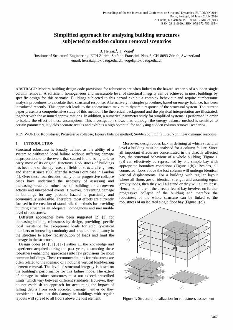
Moreover, design codes lack in defining at which structural level a building must be analysed for a column failure. Since all important effects are concentrated in the directly affected bay, the structural behaviour of a whole building (Figure 1 (a)) can effectively be represented by one simple bay with appropriate boundary conditions (Figure 1(b)). Besides, all connected floors above the lost column will undergo identical vertical displacements. For a building with regular layout where all floors are of identical strength and assuming equal gravity loads, then they will all stand or they will all collapse. Hence, no failure of the direct affected bay involves no further progressive collapse of the building and therefore the robustness of the whole structure can be linked to the robustness of an isolated single floor bay (Figure 1(c)).
Figure 1. Structural idealization for robustness assessment
a)
b) c)
Simplified approach for analysing building structures subjected to sudden column removal scenarios
B. Herraiz1, T. Vogel1
1Institute of Structural Engineering, ETH Zürich, Stefano-Franscini-Platz 5, CH-8093 Zürich, Switzerland email: [email protected], [email protected]
Proceedings of the 9th International Conference on Structural Dynamics, EURODYN 2014
3468
A further considerable shortcoming is that most of these standards do not give specific guidance about how the structural analysis for this hazard scenario should be performed. In this direction, different investigations and guidelines [5] [6] [8] have underlined the feasibility of an instantaneous column failure, which is a more appropriate design scenario. Hence, an upper bound of the dynamic component of the phenomenon is determined.
With that being said, sudden column removal presents relevant advantages in order to be the leading standard scenario when designing a building structure for robustness. It is hazard-independent, as the column is notionally removed; designing for this event provides the building a sufficient and homogeneous level of structural robustness; by assuming an instantaneous failure mode the dynamic effects are standardized; and the behaviour depends on the individual performance of the directly affected area and therefore it is independent of the overall scheme of the building.
2 SUDDEN COLUMN REMOVAL SCENARIOS When a column is instantaneously removed, compressive forces in all columns above the target column will vanish within few milliseconds and will be redistributed to the neighbouring supports. The redistribution of the dynamic gravity loads of each floor is carried out by the horizontal structural members, bridging over the lost column and deflecting until a new equilibrium position is reached. Collapse will take place if this equilibrium is not possible or if the vertical load bearing elements fail due to the supplementary compression forces. However, columns generally are capable to accommodate this increase and consequently only the behaviour of the horizontal structural components and their connexion with the supports are relevant for the collapse resistance of buildings.
On the other hand, the structural response of a building subjected to a sudden loss of a vertical load bearing element is highly complex, involving structural dynamics as well as material and geometrical nonlinearities due to the expected large strains and displacements [9].
Analysing and modelling this event through nonlinear time history approaches is not simple and requires expertise by qualified specialists with experience in nonlinear dynamic structural response and higher-order structural theory. It is therefore unsurprising that structural engineers prefer static approaches with simplified dynamic effects for ordinary building design and evaluation. However, linear analysis approaches with dynamic increase factors do not represent the structural behaviour in the inelastic range accurately.
Alternatively, a simplified method for the analysis of this hazard is available. This method was originally introduced for blast resistant design by Newmark [10] and further developed for sudden column failure scenarios by several authors [11] [12] [13]. The approach consists in a nonlinear static pushover and simplified dynamic response procedure based on energy balance, which is a compromise between accuracy and complexity. Approaches based on energy balance provide in general more precise structural robustness assessments than linear elastic approaches because they include energy absorption capacity, ductility supply and redundancy in the analysis [13].
3 ENERGY BALANCE METHOD
3.1 Description of the method and physical interpretation The energy balance method provides the approximate maximum dynamic deflection of a reference point from the considered substructure for a specific loading level. This parameter is enough to assess the robustness of the structure, as the main concern is to avoid its collapse and therefore just the overall maximum response is required.
This simplified approach assumes that a structure subjected to a column removal only experiments vertical deflection and no horizontal translation, which is quite realistic. Furthermore, the method is based upon the principle that sudden column removal is similar in effect to apply a step load of the gravity forces on the affected assembly. Immediately after the sudden application of these gravity forces, equilibrium is not satisfied and the deflections become larger in order to increase the strain energy of the system. The excess of external work done is transformed into kinetic energy, increasing the velocity of the structural system. As the structure deflects, the kinetic energy decreases, and the structure absorbs the potential energy of the gravity loads in form of elastic and inelastic energy. The maximum dynamic response is reached when the work done by the gravity loads is equal to the stored strain energy of the structure, and hence the kinetic energy is zero.
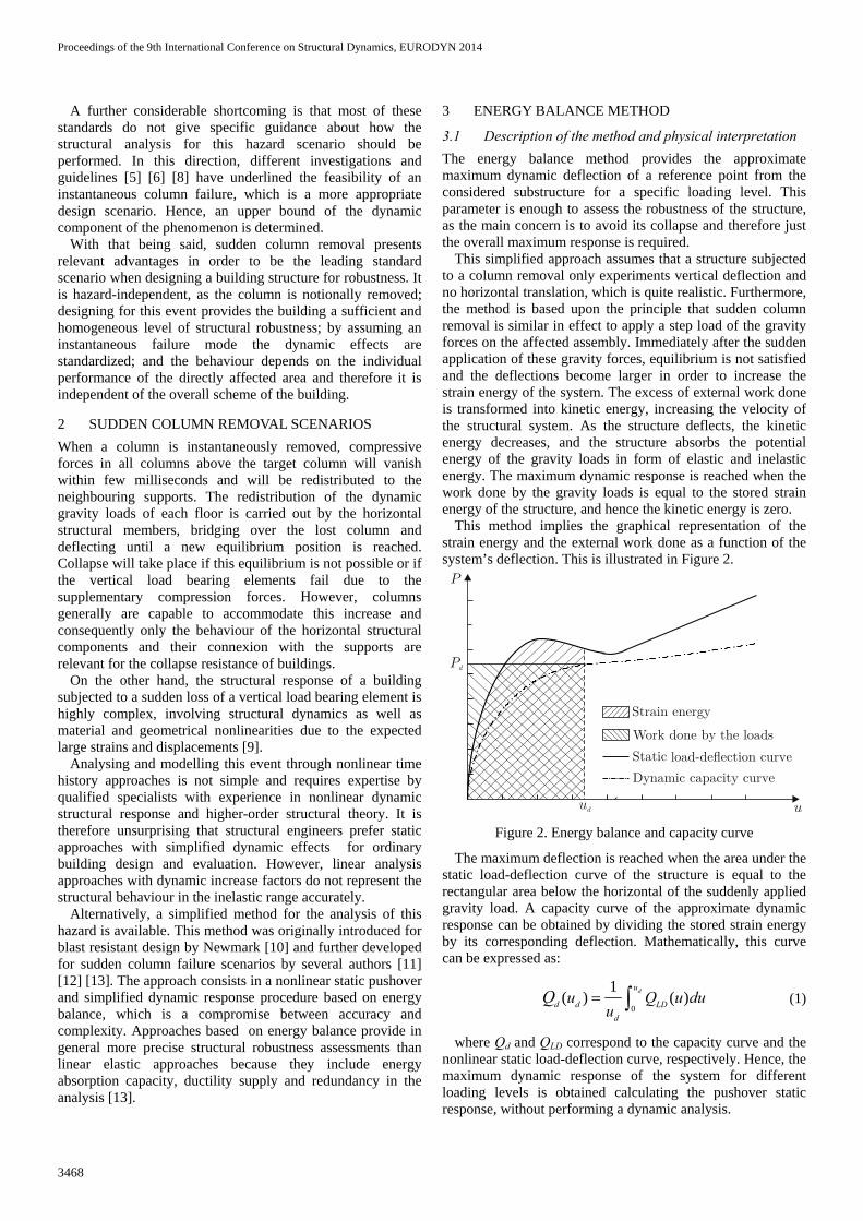
This method implies the graphical representation of the strain energy and the external work done as a function of the system’s deflection. This is illustrated in Figure 2.
Figure 2. Energy balance and capacity curve
The maximum deflection is reached when the area under the static load-deflection curve of the structure is equal to the rectangular area below the horizontal of the suddenly applied gravity load. A capacity curve of the approximate dynamic response can be obtained by dividing the stored strain energy by its corresponding deflection. Mathematically, this curve can be expressed as:
0
1( ) ( )du
d d LDd
u Q u duu
Q = ∫ (1)
where Qd and QLD correspond to the capacity curve and the nonlinear static load-deflection curve, respectively. Hence, the maximum dynamic response of the system for different loading levels is obtained calculating the pushover static response, without performing a dynamic analysis.
Pd
ud
P
u
l
Proceedings of the 9th International Conference on Structural Dynamics, EURODYN 2014
3469
Nevertheless, the energy balance method only yields exact results for structural models that have a single degree of freedom (SDOF) for the whole dynamic response. For real structures with infinite degrees of freedom, the simplified method yields approximate results and is based on the static pushover analysis. Furthermore, the method does not consider the energy dissipated by viscous damping and neither does directly take in account the effects that the strain rate can have in the structural response. All these points are further analysed in the following paragraphs.
3.2 Step gravity load as a sudden column removal The energy balance method assumes that the event of a sudden column failure is similar in effect to an instantaneous application of the gravity loads. The implicit error of this hypothesis arises from the fact that all the work done by the loads is considered to have a dynamic nature, when in reality a portion of this external work is static due to the primary deformations before the column is removed. This leads to overestimations in the maximum dynamic deflections. Besides, for structures subjected to an uniform step load these maximum deflections occur at their mid-point while for real column failure scenarios they do not always take place at that point. These approximations are, however, valid whenever the dynamic deflections originated by the step load are much larger than the static deflections caused by the gravity loads with the original configuration. In that case, the difference of the total external work and the dynamic deflection between the exact and the approximate solutions is negligible.
The larger errors occur when the structure remains in the elastic region under the step load. An inelastic behaviour leads to larger dynamic deflections and thus smaller relative errors.
For the purpose of analysing the relevance of this assumption in the accuracy of the results, a parameter study has been performed for simplified linear elastic systems.
Throughout this paper, the relative error between two deflections expressed in percentage terms is defined as:
100 a e
e
u ue
u−
= ⋅⎛ ⎞⎜ ⎟⎝ ⎠
(2)
being ua the approximate maximum deflection of the system given by the energy balance method and ue the maximum deflection given by a more rigorous analysis.
First, a linear elastic simply supported beam is analysed for a variable position of the removed column along the span as shown in Figure 3.
Figure 3. Outline of the beam configuration
In the following diagram (Figure 4), for a given specific gravity loading, the relative error between the maximum deflection along the beam for the rigorous solution as sudden column removal and the approximate solution as sudden application of the loads for different values of ψ is plotted. In addition, the ratio of the maximum deflection of the step load
to the maximum static deflection of the original configuration with the support, known as dynamic factor, is displayed.
Figure 4. Relative error of the deflection and dynamic factor
The relative error is substantially zero when the support is in the centre of the beam, and increases while decreasing the value of ψ, i.e. when approaching the removed column to the end supports and making the structural configuration less symmetric. However, for values of ψ around 0.3 and ratio of the long span to the short span around 2, the error remains around 5%, which is a typical uncertainty to assume in structural engineering. This shows that, for the most usual layouts of building’s beam frames, assuming a step load as a sudden column removal does not lead to large relative errors. Furthermore, there is a very good correlation between the dynamic factor and the relative error, highlighting the fact that a large value of this factor assures the accuracy of the method.
In a second stage, a linear elastic simply supported slab is investigated for different aspect ratios γ and for a variable position of the removed column along the reference span b with a fixed distance a/2 as presented in Figure 5:
Figure 5. Outline of the slab configuration
Again, for a given specific gravity load, the relative error of the maximum deflection along the slab between both approaches for different values of γ and ψ is calculated. The results of this analysis are plotted in Figure 6:
L
Sudden removed column
0.1 0.15 0.2 0.25 0.3 0.35 0.4 0.45 0.5
15
10
5
0
20
80
60
40
20
0
0.1 0.15 0.2 0.25 0.3 0.35 0.4 0.45 0.5
ψ
ψ
b
a
ψ b
Suddenremovedcolumn
a2
Aspect ratio
= ab
γ
Simplysupported
Proceedings of the 9th International Conference on Structural Dynamics, EURODYN 2014
3470
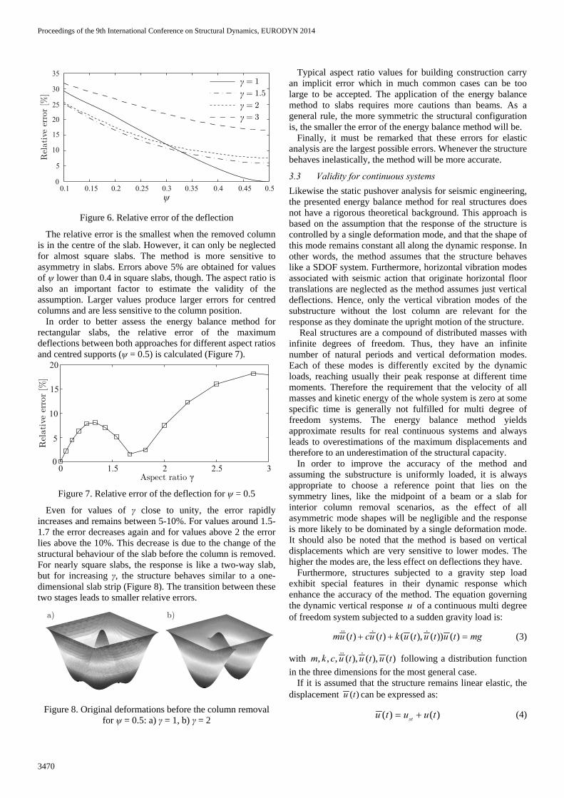
Figure 6. Relative error of the deflection
The relative error is the smallest when the removed column is in the centre of the slab. However, it can only be neglected for almost square slabs. The method is more sensitive to asymmetry in slabs. Errors above 5% are obtained for values of ψ lower than 0.4 in square slabs, though. The aspect ratio is also an important factor to estimate the validity of the assumption. Larger values produce larger errors for centred columns and are less sensitive to the column position.
In order to better assess the energy balance method for rectangular slabs, the relative error of the maximum deflections between both approaches for different aspect ratios and centred supports (ψ = 0.5) is calculated (Figure 7).
Figure 7. Relative error of the deflection for ψ = 0.5
Even for values of γ close to unity, the error rapidly increases and remains between 5-10%. For values around 1.5-1.7 the error decreases again and for values above 2 the error lies above the 10%. This decrease is due to the change of the structural behaviour of the slab before the column is removed. For nearly square slabs, the response is like a two-way slab, but for increasing γ, the structure behaves similar to a one-dimensional slab strip (Figure 8). The transition between these two stages leads to smaller relative errors.
Figure 8. Original deformations before the column removal
for ψ = 0.5: a) γ = 1, b) γ = 2
Typical aspect ratio values for building construction carry an implicit error which in much common cases can be too large to be accepted. The application of the energy balance method to slabs requires more cautions than beams. As a general rule, the more symmetric the structural configuration is, the smaller the error of the energy balance method will be.
Finally, it must be remarked that these errors for elastic analysis are the largest possible errors. Whenever the structure behaves inelastically, the method will be more accurate.
3.3 Validity for continuous systems Likewise the static pushover analysis for seismic engineering, the presented energy balance method for real structures does not have a rigorous theoretical background. This approach is based on the assumption that the response of the structure is controlled by a single deformation mode, and that the shape of this mode remains constant all along the dynamic response. In other words, the method assumes that the structure behaves like a SDOF system. Furthermore, horizontal vibration modes associated with seismic action that originate horizontal floor translations are neglected as the method assumes just vertical deflections. Hence, only the vertical vibration modes of the substructure without the lost column are relevant for the response as they dominate the upright motion of the structure.
Real structures are a compound of distributed masses with infinite degrees of freedom. Thus, they have an infinite number of natural periods and vertical deformation modes. Each of these modes is differently excited by the dynamic loads, reaching usually their peak response at different time moments. Therefore the requirement that the velocity of all masses and kinetic energy of the whole system is zero at some specific time is generally not fulfilled for multi degree of freedom systems. The energy balance method yields approximate results for real continuous systems and always leads to overestimations of the maximum displacements and therefore to an underestimation of the structural capacity.
In order to improve the accuracy of the method and assuming the substructure is uniformly loaded, it is always appropriate to choose a reference point that lies on the symmetry lines, like the midpoint of a beam or a slab for interior column removal scenarios, as the effect of all asymmetric mode shapes will be negligible and the response is more likely to be dominated by a single deformation mode. It should also be noted that the method is based on vertical displacements which are very sensitive to lower modes. The higher the modes are, the less effect on deflections they have.
Furthermore, structures subjected to a gravity step load exhibit special features in their dynamic response which enhance the accuracy of the method. The equation governing the dynamic vertical response u of a continuous multi degree of freedom system subjected to a sudden gravity load is:
( ) ( ) ( ( ), ( )) ( )+ + =&& & &mu t cu t k u t u t u t mg (3)
with , , , ( ), ( ), ( )m k c u t u t u t&& & following a distribution function in the three dimensions for the most general case.
If it is assumed that the structure remains linear elastic, the displacement ( )u t can be expressed as:
( ) ( )= +stu t u u t (4)
0.1 0.15 0.2 0.25 0.3 0.35 0.4 0.45 0.5
15
10
5
0
20
25
30
35
γ
γ
γ
γ
ψ
0 1.5 2 2.5 30
5
10
15
20
γ
a) b)
Proceedings of the 9th International Conference on Structural Dynamics, EURODYN 2014
3471
Being u the displacement measured from the static position and ust the static deflection of the structure subjected to the gravity step load. Hence, the equation can be rewritten as the free vibration problem:
( ) ( ) ( ) 0+ + =&& &mu t cu t ku t (5)
with the initial conditions:
(0) (0) 0= − =&stu u u (6)
Neglecting damping, the displacement u is given by:
( ) ( )( )1
( ) cos sinω ω φ∞
=
= +∑ n n n n nn
u t A t B t (7)
Substituting initial displacements and velocities for equation (7) yields:
1 1
(0) (0) 0φ φ∞ ∞
= =
= − = = =∑ ∑&st n n n nn n
u u A u B (8)
Assuming that the fundamental vibration mode is the static deflection shape under the uniform gravity step load and taking in consideration that, in linear elastic systems, the contribution of vibration modes to others is zero due to the orthogonality property lead to:
1 2... 1...1, 0 0= − = =n nA A B (9)
and therefore:
( )1( ) cos ω= − stu t t u (10)
Substituting equation (10) in equation (4) yields:
( )( )1( ) 1 cos ω= −stu t u t (11)
Hence, these structures exhibit a single deformation mode for uniform suddenly applied loads and the analysis leads to the commonly known result that the maximum displacement of a system under a step load is twice the static deflection. The same outcome is obtained by using force-dependent Ritz vectors as mode shapes [14]. The first Ritz vector is the static deflection corresponding to the step load. Further Ritz vectors do not excite any mass degree of freedom and are neglected. Thus, the structure has just one mode shape. This implies that, for linear elastic systems, the energy balance method is exact. However, for nonlinear dynamic responses these assumptions do not hold and the method leads to approximate results.
On the other hand, the response of inelastic systems is not totally different from the behaviour of elastic systems. Hence, it is reasonable to expect that the modes are weakly coupled [14] and that the first load-dependent Ritz vector, for each independent nonlinear deformation, dominates the response.
Assessing the implicit error of the energy balance method applied to a nonlinear dynamic response of a structure is not a straightforward task. This error depends on a broad number of variables like structural configuration, geometry, position and dimension of the plastic hinges or yield lines, nonlinear behaviour of the material, assumed level of loading, available ductility in the plastic regions, etc. Therefore, there is no
global algorithm which evaluates in a measurable way the error introduced in the displacement calculations when employing the energy balance method for inelastic systems.
In order to better illustrate the aforementioned problems, a simple example is proposed. The dynamic analysis of a fully clamped beam subjected to a step load for different loading levels is accomplished. The beam is considered to be massless (the dynamic mass is associated to the loads, as it would be in a real case), with a constant cross section and isotropic material. No damping or strain-rate effects are considered in this analysis. The material is assumed to be perfect linear elastic-plastic with formation of plastic hinges where all the plastic deformation is concentrated. The different stages and configurations of the structural system during the loading process are represented in Figure 9.
Figure 9. Different phases of the structural system during the
loading process: a) Fully clamped beam; b) Elastic-plastic beam; c) Collapse mechanism
The maximum displacements of the beam’s midpoint for different loading levels are obtained for the static and the time history dynamic response. Furthermore, the capacity curve is calculated. Only material nonlinearities are considered in the analyses, geometrical nonlinearities were neglected.
Both, static and time history dynamic analyses are calculated through the finite element software SAP 2000 [15]. This program allows modelling the formation of user-defined plastic hinges in specific regions of the structure. During the hinge unloading, the program was defined to apply local load redistribution for both analyses. When the hinge reaches its bearing capacity, a temporary, localized, self-equilibrating, internal load is applied on the hinge, unloading it. Once this process is done, the temporary load is reversed, redistributing the removed load to the neighbouring elements imitating the effect of local inertia forces balancing a rapidly unloading element. The static response has been calculated through a downwards pushover static analysis of the beam’s midpoint. For the analysis of the time history dynamic response, an implicit direct integration method has been chosen.
Once the nonlinear static response has been obtained, the dynamic capacity curve is calculated by applying equation (1).
The outcome of the above described analysis, together with the absolute and relative errors of the maximum deflections (as defined in equation (2)) for specific loading levels between the rigorous time history dynamic response and the approximate dynamic capacity curve, are displayed for the correspondent ductility values in Figure 10.
b)
c)
a)
P qL=
L
P qL=
P qL=
L
L
Proceedings of the 9th International Conference on Structural Dynamics, EURODYN 2014
3472
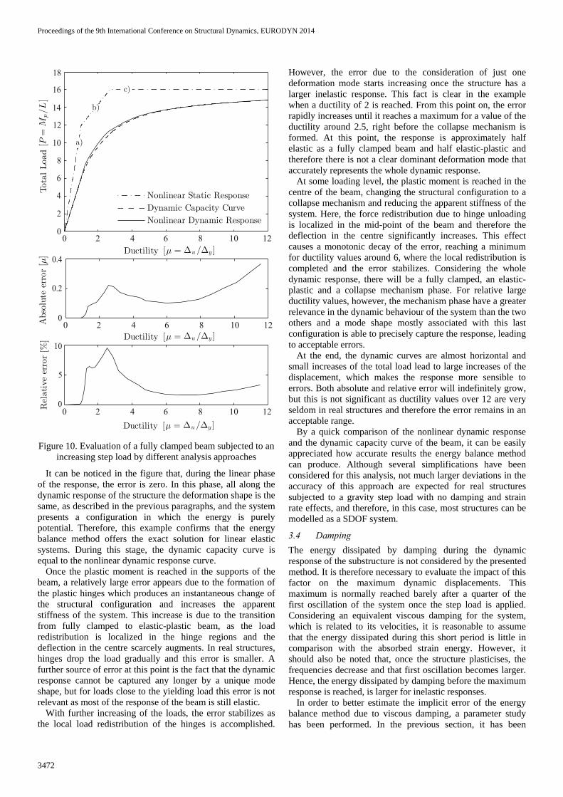
Figure 10. Evaluation of a fully clamped beam subjected to an
increasing step load by different analysis approaches
It can be noticed in the figure that, during the linear phase of the response, the error is zero. In this phase, all along the dynamic response of the structure the deformation shape is the same, as described in the previous paragraphs, and the system presents a configuration in which the energy is purely potential. Therefore, this example confirms that the energy balance method offers the exact solution for linear elastic systems. During this stage, the dynamic capacity curve is equal to the nonlinear dynamic response curve.
Once the plastic moment is reached in the supports of the beam, a relatively large error appears due to the formation of the plastic hinges which produces an instantaneous change of the structural configuration and increases the apparent stiffness of the system. This increase is due to the transition from fully clamped to elastic-plastic beam, as the load redistribution is localized in the hinge regions and the deflection in the centre scarcely augments. In real structures, hinges drop the load gradually and this error is smaller. A further source of error at this point is the fact that the dynamic response cannot be captured any longer by a unique mode shape, but for loads close to the yielding load this error is not relevant as most of the response of the beam is still elastic.
With further increasing of the loads, the error stabilizes as the local load redistribution of the hinges is accomplished.
However, the error due to the consideration of just one deformation mode starts increasing once the structure has a larger inelastic response. This fact is clear in the example when a ductility of 2 is reached. From this point on, the error rapidly increases until it reaches a maximum for a value of the ductility around 2.5, right before the collapse mechanism is formed. At this point, the response is approximately half elastic as a fully clamped beam and half elastic-plastic and therefore there is not a clear dominant deformation mode that accurately represents the whole dynamic response.
At some loading level, the plastic moment is reached in the centre of the beam, changing the structural configuration to a collapse mechanism and reducing the apparent stiffness of the system. Here, the force redistribution due to hinge unloading is localized in the mid-point of the beam and therefore the deflection in the centre significantly increases. This effect causes a monotonic decay of the error, reaching a minimum for ductility values around 6, where the local redistribution is completed and the error stabilizes. Considering the whole dynamic response, there will be a fully clamped, an elastic-plastic and a collapse mechanism phase. For relative large ductility values, however, the mechanism phase have a greater relevance in the dynamic behaviour of the system than the two others and a mode shape mostly associated with this last configuration is able to precisely capture the response, leading to acceptable errors.
At the end, the dynamic curves are almost horizontal and small increases of the total load lead to large increases of the displacement, which makes the response more sensible to errors. Both absolute and relative error will indefinitely grow, but this is not significant as ductility values over 12 are very seldom in real structures and therefore the error remains in an acceptable range.
By a quick comparison of the nonlinear dynamic response and the dynamic capacity curve of the beam, it can be easily appreciated how accurate results the energy balance method can produce. Although several simplifications have been considered for this analysis, not much larger deviations in the accuracy of this approach are expected for real structures subjected to a gravity step load with no damping and strain rate effects, and therefore, in this case, most structures can be modelled as a SDOF system.
3.4 Damping The energy dissipated by damping during the dynamic response of the substructure is not considered by the presented method. It is therefore necessary to evaluate the impact of this factor on the maximum dynamic displacements. This maximum is normally reached barely after a quarter of the first oscillation of the system once the step load is applied. Considering an equivalent viscous damping for the system, which is related to its velocities, it is reasonable to assume that the energy dissipated during this short period is little in comparison with the absorbed strain energy. However, it should also be noted that, once the structure plasticises, the frequencies decrease and that first oscillation becomes larger. Hence, the energy dissipated by damping before the maximum response is reached, is larger for inelastic responses.
In order to better estimate the implicit error of the energy balance method due to viscous damping, a parameter study has been performed. In the previous section, it has been
0 2 4 6 8 10 12
0 2 4 6 8 10 12
0 2 4 6 8 10 12
8
16
14
12
10
6
4
2
0
18
10
5
0
0
0.2
0.4
Proceedings of the 9th International Conference on Structural Dynamics, EURODYN 2014
3473
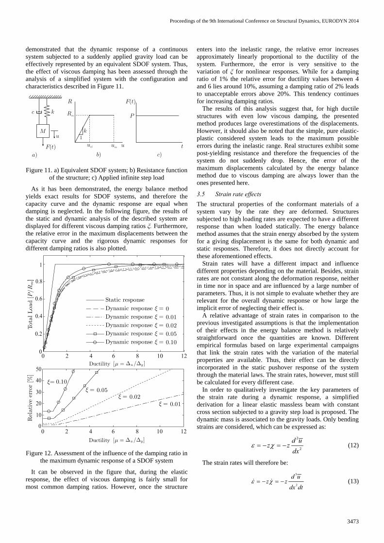
demonstrated that the dynamic response of a continuous system subjected to a suddenly applied gravity load can be effectively represented by an equivalent SDOF system. Thus, the effect of viscous damping has been assessed through the analysis of a simplified system with the configuration and characteristics described in Figure 11.
Figure 11. a) Equivalent SDOF system; b) Resistance function
of the structure; c) Applied infinite step load
As it has been demonstrated, the energy balance method yields exact results for SDOF systems, and therefore the capacity curve and the dynamic response are equal when damping is neglected. In the following figure, the results of the static and dynamic analysis of the described system are displayed for different viscous damping ratios ξ. Furthermore, the relative error in the maximum displacements between the capacity curve and the rigorous dynamic responses for different damping ratios is also plotted.
Figure 12. Assessment of the influence of the damping ratio in
the maximum dynamic response of a SDOF system
It can be observed in the figure that, during the elastic response, the effect of viscous damping is fairly small for most common damping ratios. However, once the structure
enters into the inelastic range, the relative error increases approximately linearly proportional to the ductility of the system. Furthermore, the error is very sensitive to the variation of ξ for nonlinear responses. While for a damping ratio of 1% the relative error for ductility values between 4 and 6 lies around 10%, assuming a damping ratio of 2% leads to unacceptable errors above 20%. This tendency continues for increasing damping ratios.
The results of this analysis suggest that, for high ductile structures with even low viscous damping, the presented method produces large overestimations of the displacements. However, it should also be noted that the simple, pure elastic-plastic considered system leads to the maximum possible errors during the inelastic range. Real structures exhibit some post-yielding resistance and therefore the frequencies of the system do not suddenly drop. Hence, the error of the maximum displacements calculated by the energy balance method due to viscous damping are always lower than the ones presented here.
3.5 Strain rate effects The structural properties of the conformant materials of a system vary by the rate they are deformed. Structures subjected to high loading rates are expected to have a different response than when loaded statically. The energy balance method assumes that the strain energy absorbed by the system for a giving displacement is the same for both dynamic and static responses. Therefore, it does not directly account for these aforementioned effects.
Strain rates will have a different impact and influence different properties depending on the material. Besides, strain rates are not constant along the deformation response, neither in time nor in space and are influenced by a large number of parameters. Thus, it is not simple to evaluate whether they are relevant for the overall dynamic response or how large the implicit error of neglecting their effect is.
A relative advantage of strain rates in comparison to the previous investigated assumptions is that the implementation of their effects in the energy balance method is relatively straightforward once the quantities are known. Different empirical formulas based on large experimental campaigns that link the strain rates with the variation of the material properties are available. Thus, their effect can be directly incorporated in the static pushover response of the system through the material laws. The strain rates, however, must still be calculated for every different case.
In order to qualitatively investigate the key parameters of the strain rate during a dynamic response, a simplified derivation for a linear elastic massless beam with constant cross section subjected to a gravity step load is proposed. The dynamic mass is associated to the gravity loads. Only bending strains are considered, which can be expressed as:
2
2
d uz z
dxε χ= − = − (12)
The strain rates will therefore be:
3
2
d uz z
dx dtε χ= − = −& & (13)
uM
k
F t( ) u
R
Rm
uel um t
P
F t( )
a) b) c)
c
k1
0 2 4 6 8 10 12
1
0.6
0.4
0.2
0
40
50
30
20
10
0
0.8
0 2 4 6 8 10 12
1
0.6
0.4
0.2
0
40
50
30
20
10
0
0.8
0 2 4 6 8 10 12
Proceedings of the 9th International Conference on Structural Dynamics, EURODYN 2014
3474
Substituting equation (11) in equation (13) yields:
( )3
2
2
1 12sinstd u
zdx dt
d uz t
dxε ω ω−= = −& (14)
Furthermore, the beam is reduced to a SDOF system and the strain rate in a specific point is analysed leading to the following simplifications:
2
12
1= st
st std umg mg k
uk dx k m
χ ωϕ
→ = = = (15)
with φ a constant relating the static curvatures and static displacements of a given point. Hence, equation (14) can be expressed as:
( ) ( )1 11
sin sinmg k gz
z t tk m
ε ω ωϕ ϕω
= − = −& (16)
From this derivation it can be observed that, for structures subjected to a sudden application of the standing gravity loads, the strain rates are inversely proportional to the frequency of the system. Considering a specific point of the structure, φ, z and g are all constant values and therefore this derivation suggests that, the greater or smaller the frequencies are, the smaller or larger the strain rates will be, respectively. Hence, for inelastic systems the strain rates are more significant than for elastic systems and therefore the error of the energy balance method is greater. Moreover, this error is also larger for nonlinear responses due to the fact that the accumulated strain energy, where the error lies, is larger for increasing ductility values.
Even though this derivation is not valid for generalized structures where further parameters influence the strain rates, it is reasonable to expect that this relationship holds for real structures and that, nonetheless, there is a link between strain rates and frequencies for sudden column removal scenarios.
Quantitatively, the influence of strain rates in the response of structures subjected to an instantaneous column failure has been estimated in different investigations for various materials and structural configurations. For reinforced concrete frame structures, a comprehensive study of the problem has been recently published [16]. The results of this investigation support the hypothesis that strain rates are larger for inelastic responses and underline the fact that their effects play a major role in the structural response by significantly enhancing the dynamic capacity and robustness of the building.
4 CONCLUSION Sudden column removal scenarios are currently the most widely and accepted procedure to assess the robustness of buildings. Most standards and design code provisions for robustness are linked to this hazard even though the information provided for the structural analysis of this failure is very limited due to its complexity. The energy balance method provides approximate but still fair accurate results and does not require cumbersome procedures.
The implicit error of the energy balance method arises mainly from assuming that sudden column failure is similar in effect to a step load, considering that the structural system has
a single deformation mode, which is maintained during all the deformation process and neglecting the energy dissipated by viscous damping and the effects of strain rate for the material properties. The errors due to these assumptions are very difficult to implement in the energy balance method as, in order to effectively compute them, the exact dynamic response for every particular case have to be calculated.
The results for the generic simplified systems presented in this paper can be employed to estimate the order of magnitude of the maximum displacements’ error when applying the energy balance method and, using the engineer’s judgement, assess whether or not this approach leads to acceptable results for a specific structural configuration.
A common property of all the described assumptions is that considering their effect the dynamic structural capacity is enhanced. Hence, the energy balance method always underestimates the strength of the system and therefore leads to conservative results. Furthermore, this approach contains fewer uncertainties when performing the calculation due to the reduced number of parameters necessary for the analysis. In this direction, the energy balance method is a promising approach with a high potential which, together with sudden column removal scenarios, can be proposed as the standard procedure to assess and design buildings for robustness.
REFERENCES [1] Griffith H., Pugsley A. and Saunders O., "Report of the inquiry into the
collapse of flats at Ronan Point, Canning Town," Her Majesty's Stationery Office (HMSO), London, United Kingdom, 1968.
[2] COST Action TU0601, Robustness of Structures: Final Deliverables and Report, 2011.
[3] Knoll F. and Vogel T., Design for robustness. International Association for Bridge and Structural Engineering, Zurich, Switzerland, 2009.
[4] European Committee for Standardization, EN 1991-1-7:2006. Actions on Structures, Part 1-7: General Actions — Accidental Actions, 2006.
[5] Department of Defense of the U.S.A., Unified Facilities Criteria (UFC). Design of Building to Resist Progressive Collapse, 2005.
[6] U.S. General Services Administration, Progressive Collapse Analysis and Design Guidelines, 2003.
[7] Schweizerischer Ingenieur- und Architektenverein, SIA 261:2003. Einwirkungen auf Tragwerke, Zurich, Switzerland, 2003.
[8] Müllers, I. and Vogel, T., "Column Failure as a Hazard Scenario for Flat Slab Structures," in IABSE Symposium, Lisbon, 2005, pp. 18-24(7).
[9] Müllers I., "Zur Robustheit im Hochbau — Stützenausfall als Gefährdungsbild für Stahlbetontragwerke," Institute of Structural Engineering IBK, ETH Zurich, PhD Thesis, Zurich, Switzerland, 2007.
[10] N. W. Newmark, "An Engineering Approach to Blast Resistant Design," in American Society of Civil Engineers. Structural division, vol. 79, New York City, USA, 1953.
[11] Powell G., "Progressive Collapse: Case Studies Using Nonlinear Analysis," in ASCE Structures Congress, New York City, USA, 2005.
[12] Dusenberry, D. O., and Hamburger, R. O. , "Practical Means for Energy-Based Analyses of Disproportionate Collapse Potential," Journal of Performance of Constructed Facilities, vol. 20(4), pp. 336-348, 2006.
[13] Izzuddin B.A., Vlassis A.G., Elghazouli A.Y. and Nethercot D.A., "Progressive collapse of multi-storey buildings due to sudden column loss — Part I: Simplified assessment framework," Engineering Structures, pp. 30(5): 1308-18, 2008.
[14] A. K. Chopra, Dynamics of Structures. Theory Applications to Earthquake Engineering, 3rd ed., Pearson Prentice Hall, Ed. New Jersey, USA, 2007.
[15] Computers and Structures Inc., CSI. SAP2000 V-15. Integrated finite element software for structural analysis and design. Analysis reference manual. Berkeley, USA, 2011.
[16] Santafé Iribarren B., "Progressive Collapse Simulation of Reinforced Concrete Structures: Influence of Design and Material Parameters and Investigation of the Strain Rate Effects," Université Libre de Bruxelles, Royal Military Academy, PhD Thesis, Brussels, Belgium, 2011.


![Evaluation of different automated operational modal analysis ...paginas.fe.up.pt/~eurodyn2014/CD/papers/312_MS13_ABS...monitoring approach presented in [5-7], the state-of-the-art](https://static.documents.pub/doc/80x56/60dd72570ee28946b90a49b7/evaluation-of-different-automated-operational-modal-analysis-eurodyn2014cdpapers312ms13abs.jpg)


