Technical Manual Hood Type Dishwasher Model: M-DH High Temperature with Built-in Booster April, 2003 Manual P/N 113512 Rev A Machine Serial No. www.championindustries.com P.O. Box 4183 2674 N. Service Road Winston-Salem, North Carolina 27115-4183 Jordan Station, Ontario, Canada L0R 1S0 336/661-1992 Fax: 336/661-1660 905/562-4195 Fax: 905/562-4618 Simply Engineered Better
Transcript
Technical Manual
Hood TypeDishwasher
Model:
M-DH High Temperature with Built-in Booster
April, 2003 Manual P/N 113512 Rev A
Machine Serial No.
www.championindustries.com
P.O. Box 4183 2674 N. Service RoadWinston-Salem, North Carolina 27115-4183 Jordan Station, Ontario, Canada L0R 1S0336/661-1992 Fax: 336/661-1660 905/562-4195 Fax: 905/562-4618
Simply Engineered Better
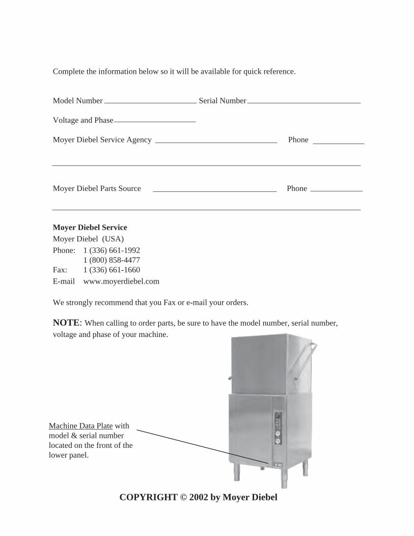
Complete the information below so it will be available for quick reference.
Model Number Serial Number
Voltage and Phase
Moyer Diebel Service Agency Phone
Moyer Diebel Parts Source Phone
Moyer Diebel ServiceMoyer Diebel (USA)
Phone: 1 (336) 661-19921 (800) 858-4477
Fax: 1 (336) 661-1660
E-mail www.moyerdiebel.com
We strongly recommend that you Fax or e-mail your orders.
NOTE: When calling to order parts, be sure to have the model number, serial number,
voltage and phase of your machine.
Machine Data Plate withmodel & serial numberlocated on the front of thelower panel.
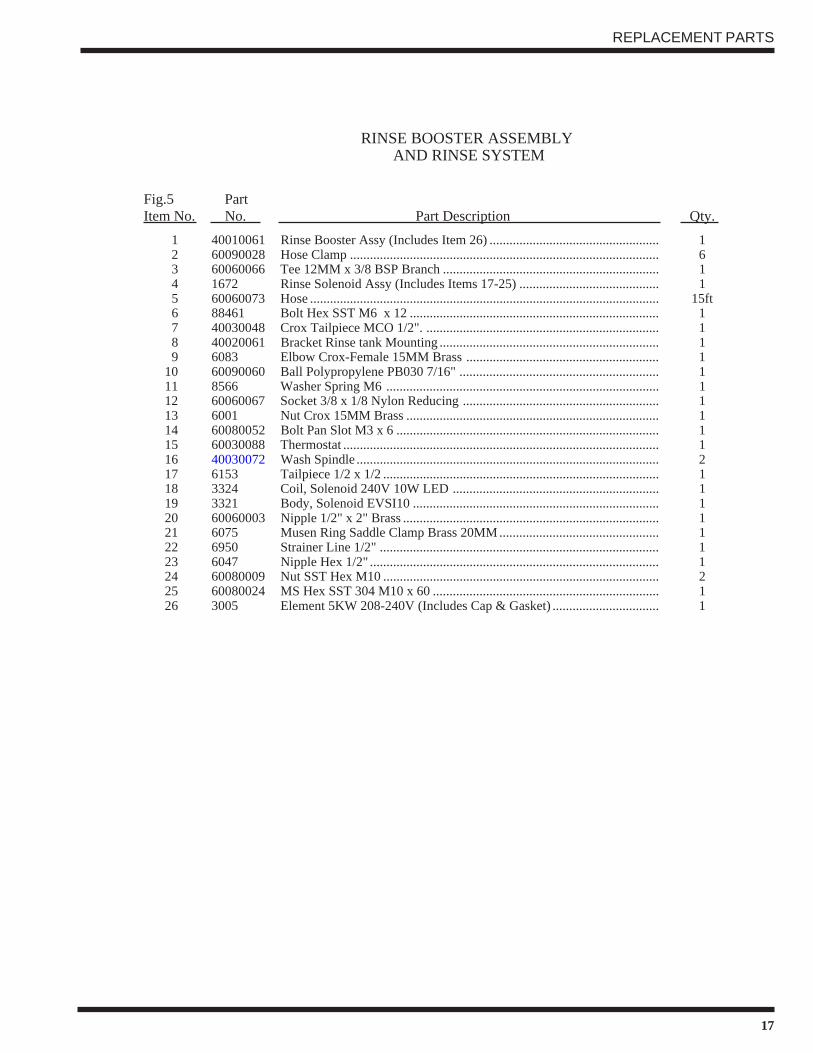
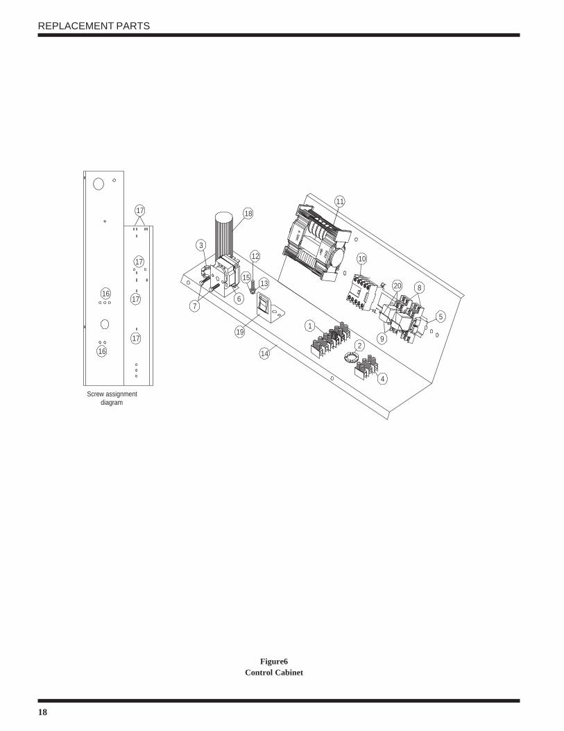
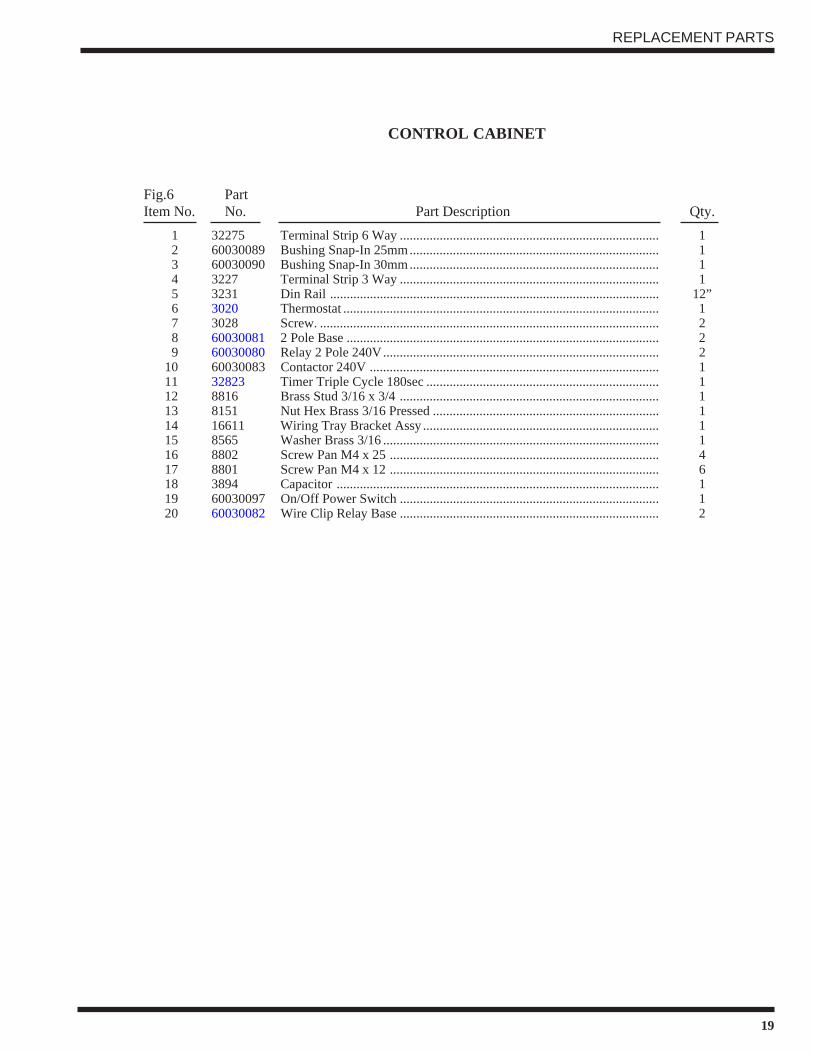
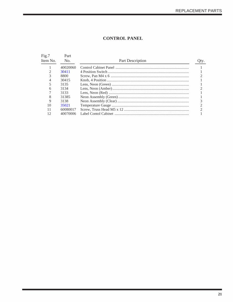
Figure 1— Front Panel ..................................................................................................................... 2Figure 2— Wiring Connection ........................................................................................................ 3Figure 2— Wash Tank Assembly .................................................................................................... 12Figure 3— Wash and Rinse Assemblies .......................................................................................... 14Figure 4— Rinse Booster Assembly and Rinse System .................................................................. 16Figure 5— Control Cabinet ............................................................................................................. 18Figure 6— Control Panel ................................................................................................................. 20
iv
THIS PAGEINTENTIONALLY
LEFT BLANK
1
GENERAL SPECIFICATION
GENERAL SPECIFICATIONS
About this manual
All information, illustrations and specifications contained in this manual are based upon thelatest product information available at the time of publication. Champion constantly improvesits products and reserves the right to make changes at any time or to change specifications ordesign without notice and without incurring any obligation.
Organization of ManualThis manual is divided into seven parts:
• General Specifications
• Installation
• Daily Operation
• Cleaning and Maintenance
• Troubleshooting
• Replacement Parts, contains parts diagrams and parts list.
• Electrical Schematics
NOTE:Unless noted otherwise, dimensions, capacities, temperatures, etc., given in this manualare U.S. Customary Measures and the Metric Equivalent of the U.S. Customary mea-sures.
ModelThe M-DH model is a high temperature (180F/82°C rinse) sanitizing model with booster.
Standard Equipment
• Automatic operation
• Built-in electric booster heater
• Field convertible to corner model
• Electric tank heat
• Extended wash/de-lime switch
• Low-water tank heat protection
• 1-hp drip-proof pump motor
• Splash-proof control console
• Door safety switch
• Common utility connections
• Detergent/chemical connectionprovisions
• Balanced door lift system
• Stainless steel front and side panels
• Interchangeable upper and lowerspray arms
• International symbols on controls
2
!
!
INSTALLATION
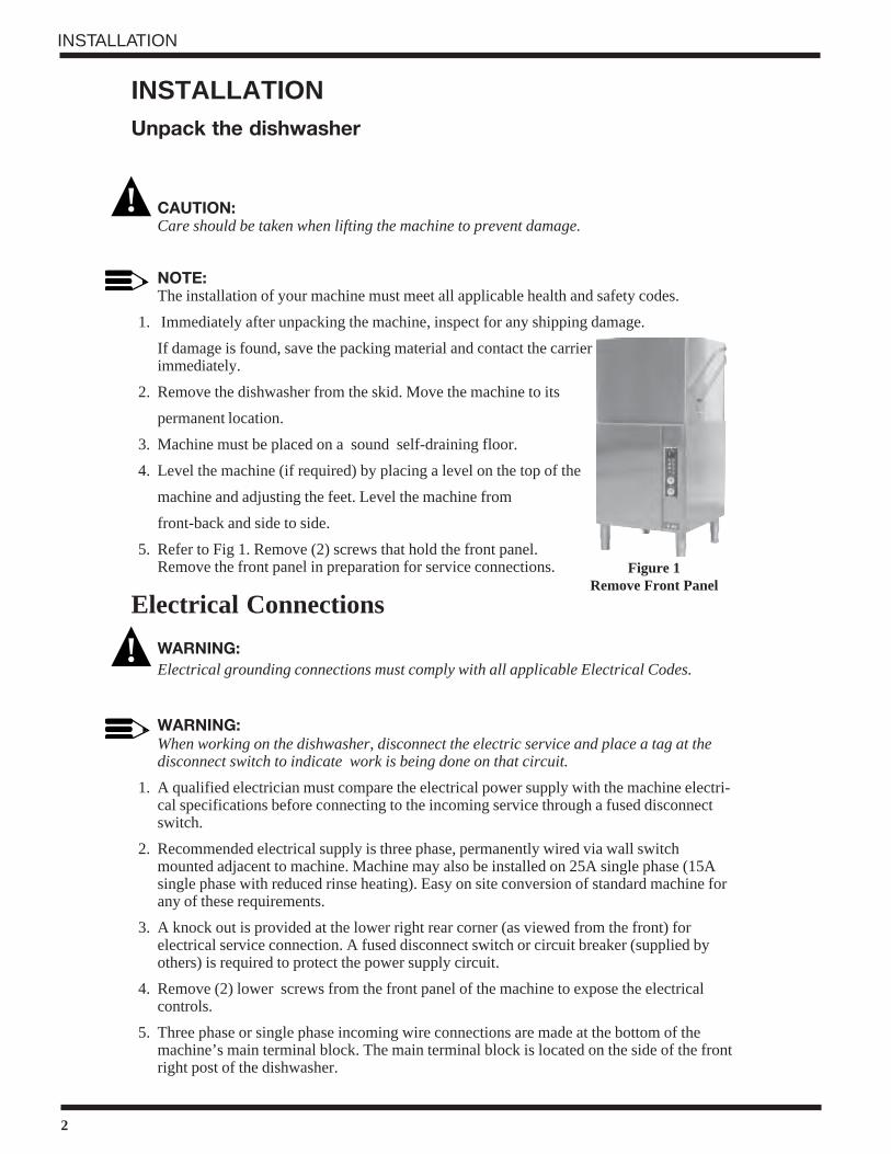
Figure 1Remove Front Panel
INSTALLATIONUnpack the dishwasher
CAUTION:Care should be taken when lifting the machine to prevent damage.
NOTE:The installation of your machine must meet all applicable health and safety codes.
1. Immediately after unpacking the machine, inspect for any shipping damage.
If damage is found, save the packing material and contact the carrierimmediately.
2. Remove the dishwasher from the skid. Move the machine to its
permanent location.
3. Machine must be placed on a sound self-draining floor.
4. Level the machine (if required) by placing a level on the top of the
machine and adjusting the feet. Level the machine from
front-back and side to side.
5. Refer to Fig 1. Remove (2) screws that hold the front panel.Remove the front panel in preparation for service connections.
Electrical Connections
WARNING:Electrical grounding connections must comply with all applicable Electrical Codes.
WARNING:When working on the dishwasher, disconnect the electric service and place a tag at thedisconnect switch to indicate work is being done on that circuit.
1. A qualified electrician must compare the electrical power supply with the machine electri-cal specifications before connecting to the incoming service through a fused disconnectswitch.
2. Recommended electrical supply is three phase, permanently wired via wall switchmounted adjacent to machine. Machine may also be installed on 25A single phase (15Asingle phase with reduced rinse heating). Easy on site conversion of standard machine forany of these requirements.
3. A knock out is provided at the lower right rear corner (as viewed from the front) forelectrical service connection. A fused disconnect switch or circuit breaker (supplied byothers) is required to protect the power supply circuit.
4. Remove (2) lower screws from the front panel of the machine to expose the electricalcontrols.
5. Three phase or single phase incoming wire connections are made at the bottom of themachine’s main terminal block. The main terminal block is located on the side of the frontright post of the dishwasher.
3
INSTALLATION
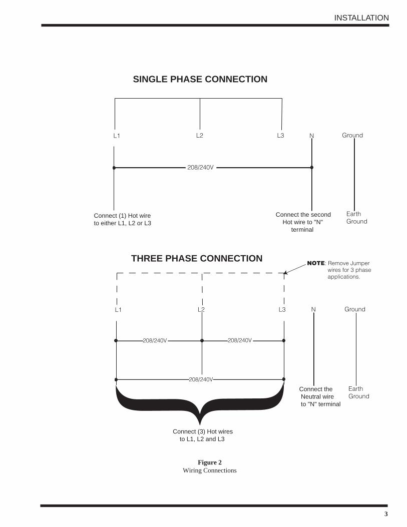
{L1 L2 L3
208/240V
N Ground
EarthGround
Connect (1) Hot wireto either L1, L2 or L3
Connect the second Hot wire to "N" terminal
SINGLE PHASE CONNECTION
L1 L2 L3 N Ground
EarthGround
Connect (3) Hot wires to L1, L2 and L3
Connect the Neutral wire to "N" terminal
THREE PHASE CONNECTIONNOTE: Remove Jumper wires for 3 phase applications.
208/240V 208/240V
208/240V
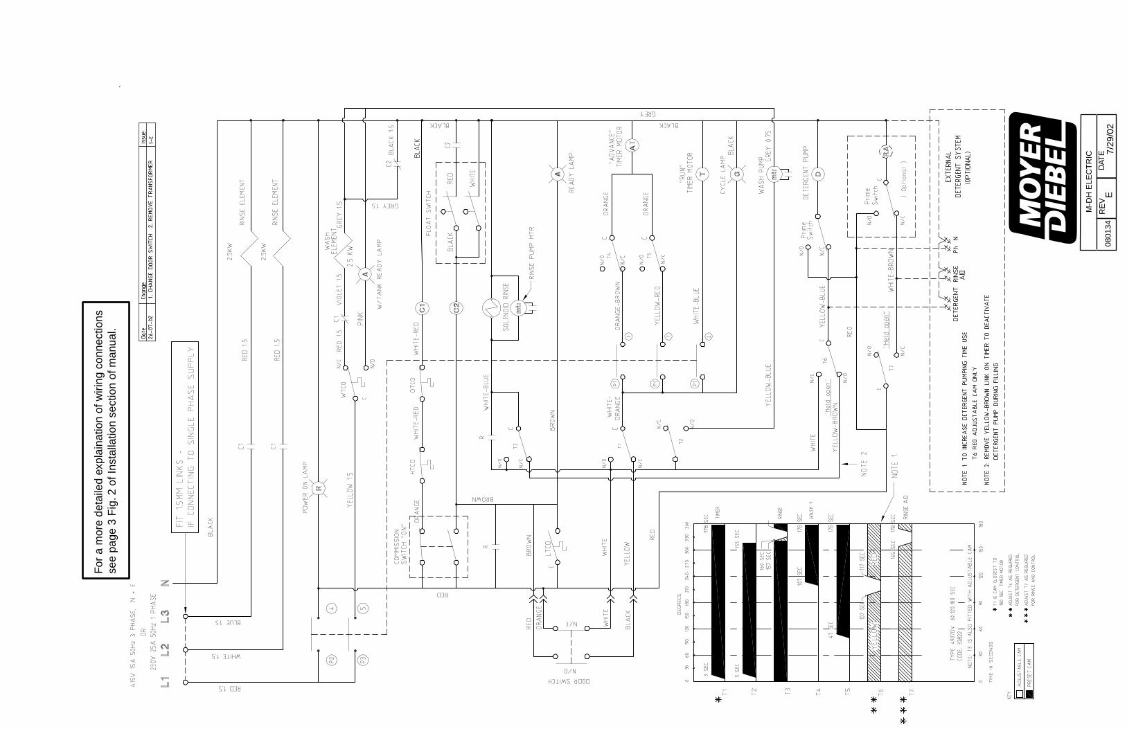
Figure 2Wiring Connections
4
!
INSTALLATION
INSTALLATION (CONT.)
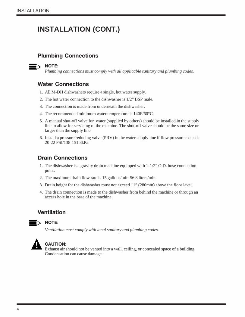
Plumbing Connections
NOTE:Plumbing connections must comply with all applicable sanitary and plumbing codes.
Water Connections1. All M-DH dishwashers require a single, hot water supply.
2. The hot water connection to the dishwasher is 1/2” BSP male.
3. The connection is made from underneath the dishwasher.
4. The recommended minimum water temperature is 140F/60°C.
5. A manual shut-off valve for water (supplied by others) should be installed in the supplyline to allow for servicing of the machine. The shut-off valve should be the same size orlarger than the supply line.
6. Install a pressure reducing valve (PRV) in the water supply line if flow pressure exceeds20-22 PSI/138-151.8kPa.
Drain Connections1. The dishwasher is a gravity drain machine equipped with 1-1/2” O.D. hose connection
point.
2. The maximum drain flow rate is 15 gallons/min-56.8 liters/min.
3. Drain height for the dishwasher must not exceed 11” (280mm) above the floor level.
4. The drain connection is made to the dishwasher from behind the machine or through anaccess hole in the base of the machine.
Ventilation
NOTE:
Ventilation must comply with local sanitary and plumbing codes.
CAUTION:Exhaust air should not be vented into a wall, ceiling, or concealed space of a building.Condensation can cause damage.
5
INSTALLATION (CONT.)
Chemical Connections
NOTE:
Consult a qualified chemical supplier for your chemical needs.
1. A chemical signal terminal block is supplied for chemical dispensing equipment.
2. The terminal block is located below the control panel fuse block.
3. The detergent signal is limited to a maximum load of 1 Amp. Signal voltage is 115VAC.
4. The Rinse aid signal is limited to a maximum load of 1 Amp. Signal voltage is 115VAC.
5. The feeder units must have separate neutrals for detergent and rinse aid connections.
6. A 1/2” detergent injection point is provided at the rear and left side of the dishwasher.
7. Detergent may be added manually, put in three tablespoons of powdered domestic deter-gent into the wash tank after the machine has been filled, then add another tablespoon fullafter every fourth or fifth cycle. This is not recommended except in a temporary situation,ex: dispensing equipment is down, out of chemical and awaiting supplier, etc.
8. Rinse aid injectors can be purchased separately. There is a 1/4” NPT rinse aid injectionpoint provided in the final rinse manifold. Use a liquid rinse aid. Contact your localchemical supplier about product type for factors such as water hardness etc.
Peristaltic Detergent Pump
To prime the peristaltic pump:
1. Insert pump inlet hose into the detergent container.
2. Close machine door and switch machine on.
3. Allow wash tank to fill up then press detergent pump prime switch to prime inlet andoutlet hose.
4. Stop priming when detergent reaches machine.
Machine will not fill unless READY light is on and door is shut. Turn power off beforeopening door as machine will cycle again when door is closed. Pump operates during the washcycle and is set to run for approximately 10 seconds. Use yellow adjusting tool, supplied withthe instructions, to adjust cam 6 to vary this time. Increase cam gap (away from 0 mark) toincrease pumping time.
INSTALLATION
6
OPERATION
INITIAL START-UPComplete the installationAfter the plumbing and electrical connections are made, follow the steps below to completethe installation of your dishwasher.
1. Remove the protective covering from the exterior of the machine.
2. Remove any foreign material from the inside of the machine.
3. Make sure dishwasher power is off.
4. Turn the main water supply on.
5. Turn main power on at the main power service disconnect switch.
6. Install the scrap screens.
7. Make sure that the overflow seats securely in the tank bottom.
8. Make sure doors are fully closed.
9. The control panel is located on the lower right side of machine. Select any cycle (1, 2, 3minutes).
10. The ON light will glow red and the machine will fill automatically.
11. When machine is full the tank heater and booster heater will begin to heat the water in thedishwasher. Wait approximately 10 minutes for the wash tank to reach operating tempera-ture. The temperature should be a minimum of 140F/60°C. The machine is ready for usewhen the READY light (tick symbol) glows amber.
OPERATIONOperation and Use1. Before washing make sure that:
• wall mounted on/off switch is switched on;
• water supply is open and water pressure is present;
• pump suction filters are installed in proper location;
• overflow tube is inserted in drain;
• rotating spray arms move freely;
• rinse and detergent containers are full;
2. Select required cycle. Try cycle 3 initially and switch to faster cycles only if necessary.
3. Scrap and preflush all items to be washed. Load items into the rack. Do not overload therack. Wash only one layer of silverware in a rack.
4. Open the door and insert the rack into machine. Close door.
NOTE:Machine will not operate unless the READY light is on. Wash temperature light (ther-mometer symbol) glows amber when wash temperature has been reached. After removingracks from machine, DO NOT shut door as machine will start up again.
7
DAILY CLEANING
1. Turn dishwasher and wall switch OFF.
2. Remove the overflow to drain wash tank.
3. Remove scrap screens and wash pump inlet screen. Rinse thoroughly to make sure thatthey are clean. Do not bang or beat them on the side of sink or other hard objects as thiswill eventually cause them to break or bend thus causing them to fit or work properly.
4. Reinstall the overflow, pump screen, and the scrap screens.
Frequently check and clean the nozzles. Blocked nozzles will prevent the machine fromcleaning properly. To clean the wash/rinse arms:
1. Undo the thumbscrew that holds the arms in place. Do not remove the retaining plate.
2. Twist and remove the end nozzle then withdraw the end cap.
3. Flush arms with water, use a toothpick or paperclip (if necessary) to clear the nozzles.
4. Do not beat the arms on anything to clean nozzles.
5. Replace end cap and end nozzle.
6. Replace arms back into position in machine.
To flush out dishwasher if needed:
1. Leave the overflow out of machine.
2. Close the door.
3. Turn power ON at the dishwasher.
4. Leave on machine on for about 20 seconds. DO NOT leave machine unattended duringthis process.
5. Shut power OFF to dishwasher.
MAINTENANCE
8
MAINTENANCE
MAINTENANCEBefore carrying out the cleaning and the maintenance operations, turn off the main disconnectswitch for the equipment.
Do not use corrosive products such as sodium hypochlorite (bleach), acids, steel wool or steelbrushes to clean the inside and the outside of machine.
The presence of calcium and magnesium salt in water can compromise machine performance.Asked a qualified chemical person to remove the deposits periodically.
Stainless steel surfaces should be cleaned well in order to avoid some oxidation risks, orchemical reactions.
Optimal Results:
Poor wash results can be noted when residue remains on the dishware. To guard against poor results,make sure of the following:
• Wash nozzles are clean.
• Rinse nozzles are clean and there is sufficient water supply pressure 20-22 PSI/138-151.8kPa.
• Water temperature is a minimum of 140F/60°C.
• Detergent is in the chemical container
• Pump suction filters are clean.
• Racks are suitable for the dishes and cutlery that are to be washed.
9
TROUBLESHOOTING
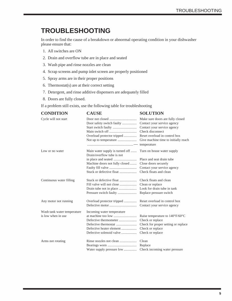
TROUBLESHOOTINGIn order to find the cause of a breakdown or abnormal operating condition in your dishwasherplease ensure that:
1. All switches are ON
2. Drain and overflow tube are in place and seated
3. Wash pipe and rinse nozzles are clean
4. Scrap screens and pump inlet screen are properly positioned
5. Spray arms are in their proper positions
6. Thermostat(s) are at their correct setting
7. Detergent, and rinse additive dispensers are adequately filled
8. Doors are fully closed.
If a problem still exists, use the following table for troubleshooting
CONDITION CAUSE SOLUTIONCycle will not start Door not closed ................................ Make sure doors are fully closed
Door safety switch faulty ................. Contact your service agencyStart switch faulty ............................ Contact your service agencyMain switch off ................................ Check disconnectOverload protector tripped ............... Reset overload in control boxNot up to temperature ...................... Give machine time to initially reach......................................................— temperature
Low or no water Main water supply is turned off ....... Turn on house water supplyDrain/overflow tube is notin place and seated ........................... Place and seat drain tubeMachine doors not fully closed ........ Close doors securelyFaulty fill valve ................................ Contact your service agencyStuck or defective float .................... Check floats and clean
Continuous water filling Stuck or defective float .................... Check floats and cleanFill valve will not close .................... Clean or replaceDrain tube not in place ..................... Look for drain tube in tankPressure switch faulty ...................... Replace pressure switch
Any motor not running Overload protector tripped ............... Reset overload in control boxDefective motor ................................ Contact your service agency
Wash tank water temperature Incoming water temperatureis low when in use at machine too low ........................... Raise temperature to 140°F/60°C
Defective thermometer ..................... Check or replaceDefective thermostat ........................ Check for proper setting or replaceDefective heater element .................. Check or replaceDefective solenoid valve .................. Check or replace
Arms not rotating Rinse nozzles not clean .................... CleanBearings worn .................................. ReplaceWater supply pressure low ............... Check incoming water pressure
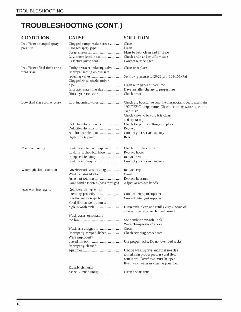
Scrap screen full ............................... Must be kept clean and in placeLow water level in tank .................... Check drain and overflow tubeDefective pump seal ......................... Contact service agent
Insufficient final rinse or no Faulty pressure reducing valve ........ Clean or replacefinal rinse Improper setting on pressure
reducing valve .................................. Set flow pressure to 20-22 psi [138-151kPa]Clogged rinse nozzle and/orpipe ................................................... Clean with paper clip/delimeImproper water line size ................... Have installer change to proper sizeRinse cycle too short ........................ Check timer
Low final rinse temperature Low incoming water ........................ Check the booster be sure the thermostat is set to maintain180°F/82°C temperature. Check incoming water is set min.
140°F/60°C.Check valve to be sure it is cleanand operating.
Defective thermometer ..................... Check for proper setting or replaceDefective thermostat ........................ ReplaceBad booster element ......................... Contact your service agencyHigh limit tripped ............................. Reset
Machine leaking Leaking at chemical injector ............ Check or replace injectorLeaking at chemical hose ................. Replace hosesPump seal leaking ............................ Replace sealLeaking at pump hose ...................... Contact your service agency
Water splashing out door Nozzles/End caps missing ................ Replace capsWash nozzles blocked ...................... CleanArms not rotating ............................. Replace bearingsDoor handle twisted (pass through) . Adjust or replace handle
Poor washing results Detergent dispenser notoperating properly ............................ Contact detergent supplierInsufficient detergents ...................... Contact detergent supplierFood Soil concentration toohigh in wash tank ............................. Drain tank, clean and refill every 2 hours of
operation or after each meal period.Wash water temperaturetoo low.............................................. See condition “Wash Tank
Water Temperature” aboveWash arm clogged ............................ CleanImproperly scraped dishes ............... Check scraping proceduresWare improperlyplaced in rack ................................... Use proper racks. Do not overload racksImproperly cleanedequipment ......................................... Unclog wash sprays and rinse nozzles
to maintain proper pressure and flowconditions. Overflows must be open.Keep wash water as clean as possible.
Electric elementshas soil/lime buildup ........................ Clean and delime
TROUBLESHOOTING
TROUBLESHOOTING (CONT.)
REPLACEMENT PARTS
11
REPLACEMENTPARTS
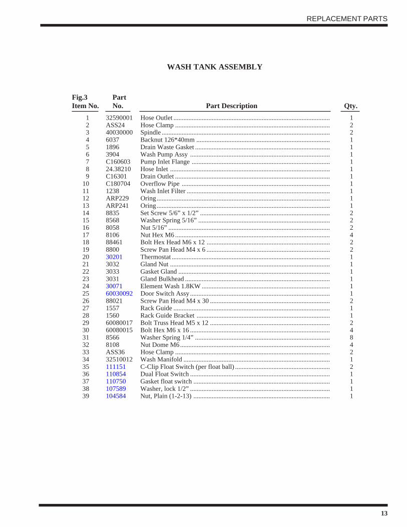
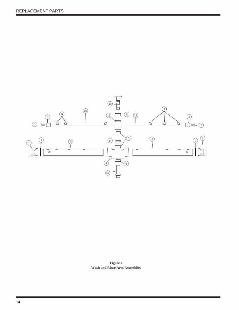
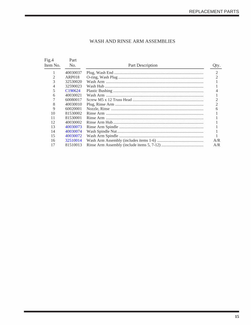
REPLACEMENT PARTS
12
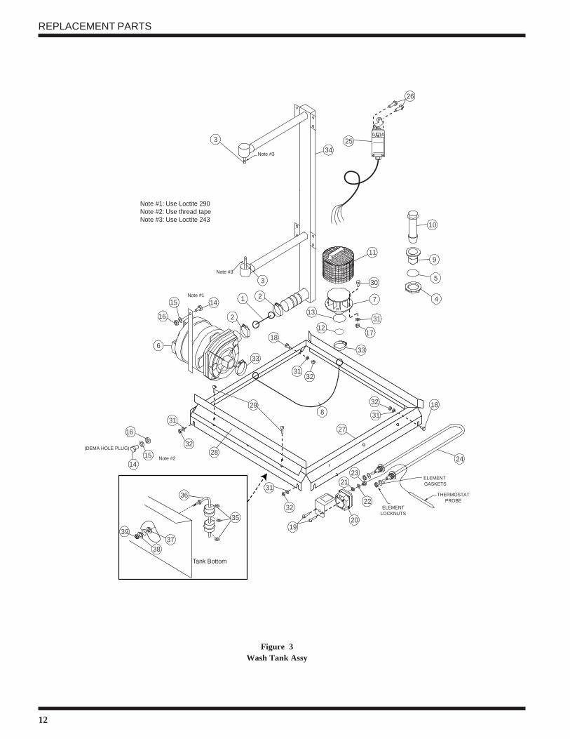
(DEMA HOLE PLUG)
Note #1: Use Loctite 290Note #2: Use thread tapeNote #3: Use Loctite 243
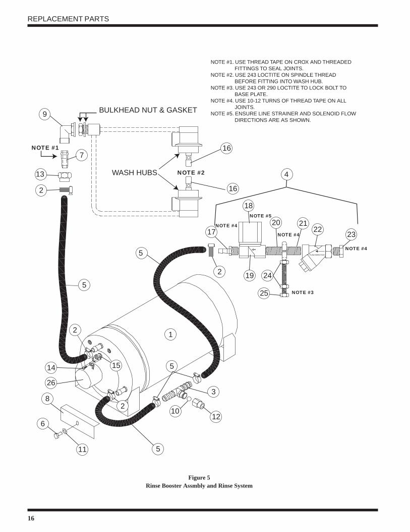
NOTE #1. USE THREAD TAPE ON CROX AND THREADED FITTINGS TO SEAL JOINTS.NOTE #2. USE 243 LOCTITE ON SPINDLE THREAD BEFORE FITTING INTO WASH HUB.NOTE #3. USE 243 OR 290 LOCTITE TO LOCK BOLT TO BASE PLATE.NOTE #4. USE 10-12 TURNS OF THREAD TAPE ON ALL JOINTS.NOTE #5. ENSURE LINE STRAINER AND SOLENOID FLOW DIRECTIONS ARE AS SHOWN.