Simulating Gnutella P2P Network Student Project (Studienarbeit) Final Report Wei Lu ([email protected]) Matrikel-Nr. 27462 Master of Information and Communication Systems Communication Networks Technical University of Hamburg-Harburg 25/02/2005
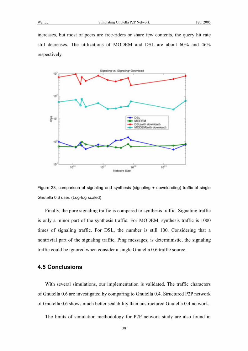
Figure 23, comparison of signaling and synthesis (signaling + download) traffic
of single Gnutella 0.6 user. (Log-log scaled) ...............................................38
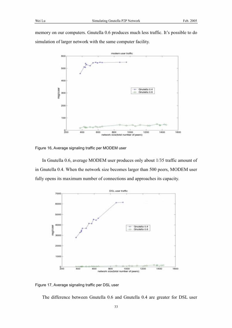
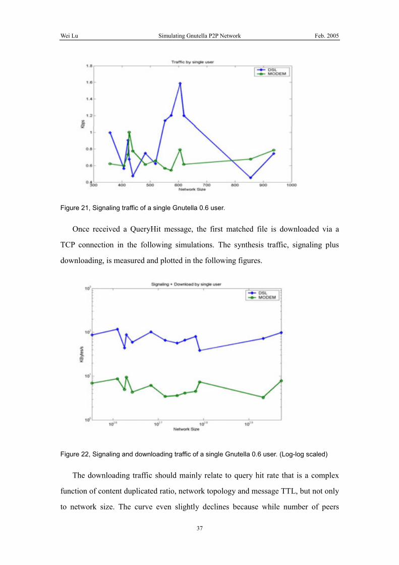
Wei Lu Simulating Gnutella P2P Network Feb. 2005
6
1 P2P network and Gnutella protocol
A Peer-to-Peer (P2P) network is an overlay network over the existing physical
internet in application layer. The main purposes include file sharing and media
content delivering.
Figure 1, general concept of P2P network
Since Napster music sharing network, many P2P networks are created, like
Gnutella, KaZaa, Freenet, JXTA, etc. Each network develops its own protocol.
Because of its open nature, the Gnutella network and protocol are frequently targeted
by academic research. Measurements and statistics are widely available as bases.
There are two versions of Gnutella protocol. The basic and widely deployed one is
version 0.4. Gnutella 0.4 is a Distributed Index Flooding Architecture (DIFA). When a
peer joins the network, it attempts to connect to Bootstrap servers to fetch initial peer
address list. Once knew other peers, PING messages are sent to each of them. The
latter relays PING messages to all known peers in a flooding manner. The flooding
scope is controlled by Time-To-Live (TTL). PONG messages are reversely routed to
the PING initiator. The initiator establishes connections to replied peers. When a user
wants to find shared files, Query messages carrying keywords are flooded to all
known-hosts. Once a peer has a matched file, a QUERYHIT message is reversely
routed to the query initiator. The matched file can be downloaded via HTTP/TCP
Wei Lu Simulating Gnutella P2P Network Feb. 2005
7
protocol from QueryHit sender by Query sender directly.
Figure 2, Schematic drawing of Gnutella 0.4
2 Gnutella protocol version 0.6
As the signaling message load in the Gnutella 0.4 network is very high and
doesn’t scale when network size increases, protocol enhancements to reduce the
signaling overhead have been proposed and resulted in a new version of the Gnutella
protocol, Gnutella 0.61.
The main solution is to create an additional hub-like network layer as follows.
Figure 3, Gnutella 0.6 network topology
Peers in Gnutella 0.6 are divided into Leaf and Ultrapeer roles to provide the hub
Wei Lu Simulating Gnutella P2P Network Feb. 2005
8
functionality. Ultrapeers establish a higher hierarchy level in which they form a pure
unstructured P2P network, i.e. are connected to each other directly via TCP
connections. Each leaf-node maintains in general only one connection to one
Ultrapeer, whereas one Ultrapeer is connected to several leaf nodes and several
Ultrapeers.
Besides the enhancements on Bootstrapping, Querying and Flow Control,
obviously, what could affect our interested merits most is the introduction of Ultrapeer
mode.
The ultrapeer extension is implemented based on Gnutella 0.4 for ns-2 simulator
referring to the Ultrapeer Proposal v1.02 discussed as follows.
2.1 Ultrapeer Election
Gnutella 0.6 peers regularly determine whether they are eligible to be ultrapeers
(“ultrapeer capable”) by looking at uptime, operating system functionality, bandwidth,
etc. Except uptime, other factors are not feasible to evaluate in our simulation. We
decide to ignore them to simplify the problem. Another solution is to ignore the
election protocol but assign peer role manually. The obstacle is that Gnutella 0.6 is not
deployed widely and lack of measurements and statistics as references. Analytical
model to derive a theoretical structure is not available either. So a simplified criteria is
used. Because every host is in an ON-OFF process except Bootstrap hosts with
bandwidth greater than 1000Mbps, the criteria is that the host who’s going to be ON
for longer than mean up-time (60 sec) is eligible to be ultrapeer.
In the beginning, the number of leaves of an ultrapeer is not limited. However, at
the first moment of a simulation, most hosts connect to few bootstraps for a start, then
they become the leaves of the bootstraps because it’s obviously that a bootstrap has
higher qualification to be ultrapeer than other hosts. It results that all bootstraps
become ultrapeers but none of other hosts. Of course, this doesn’t reflect the real
world. The reason is partly because of the small size of simulated network. However,
Wei Lu Simulating Gnutella P2P Network Feb. 2005
9
computer memory limits the size of simulated network, e.g. 2GB RAM supports
simulation of about 1000 hosts at most. In order to mimic the real world, the
maximum number of leaves of an ultrapeer is limited to 32 according to an empirical
suggestion3. I ever tried a number of 20. The simulation result looks similar to 32’s.
Further study on this could be interesting for no literature on this topic can be found
yet.
It is important to distinguish between hosts that are ultrapeer capable and hosts
that are actually ultrapeers:
Ultrapeer: hosts that are ultrapeer capable and not a shielded leaf node to an
ultrapeer. Note that an ultrapeer does not necessarily have leaf connections.
Leaf: hosts that have only a single, routed connection to an ultrapeer. Note
that leaves may actually be ultrapeer capable.
There are some header fields for Gnutella 0.6 hosts to indicate capabilities and
role intents when connect to each other. They are not implemented in the Gnutella
messages for ns-2 simulator. For efficiency, corresponding methods to enquire the
host status are instead. We use the header field name in the specification as
identifications in the following discussion.
Important header fields are:
X-Ultrapeer, tells whether a host plans on acting as an ultrapeer (if true)
or a shielded node (if false). It’s implemented as
Ultrapeer Capable (up time > mean up time) && not leave yet.
X-Ultrapeer-Needed, used to balance the number of ultrapeers. This is
discussed in detail in section “Ultrapeer to Ultrapeer, with Leaf
Guidance” below. It’s implemented as
if (X-Ultrapeer)
X-Ultrapeer-Needed = (number_of_leaves<=0);
else
Wei Lu Simulating Gnutella P2P Network Feb. 2005
10
X-Ultrapeer-Needed = is not leave.
When hosts connect, they express their capabilities and intents to negotiate the
mode of ultrapeer or leafnode. The various cases implemented are as follows.
Leaf to Ultrapeer
Client Server
iX-Ultrapeer: False
X-Ultrapeer: True
X-Ultrapeer-Needed: false
If client is already leaf node, stop the connection simply. If not, continue the
process like in Gnutella 0.4 and the server becomes ultrapeer of client. We say it that
client is shielded by server.
Leaf to Shielded Leaf
Client (A) Server (B)
X-Ultrapeer: False
X-Ultrapeer: False
[terminates connection]
B is a leaf node, the connection terminates. In future, an X-Try-Ultrapeers option
should be implemented for B to redirect A to B’s ultrapeer.
i Other fields are omitted.
Wei Lu Simulating Gnutella P2P Network Feb. 2005
11
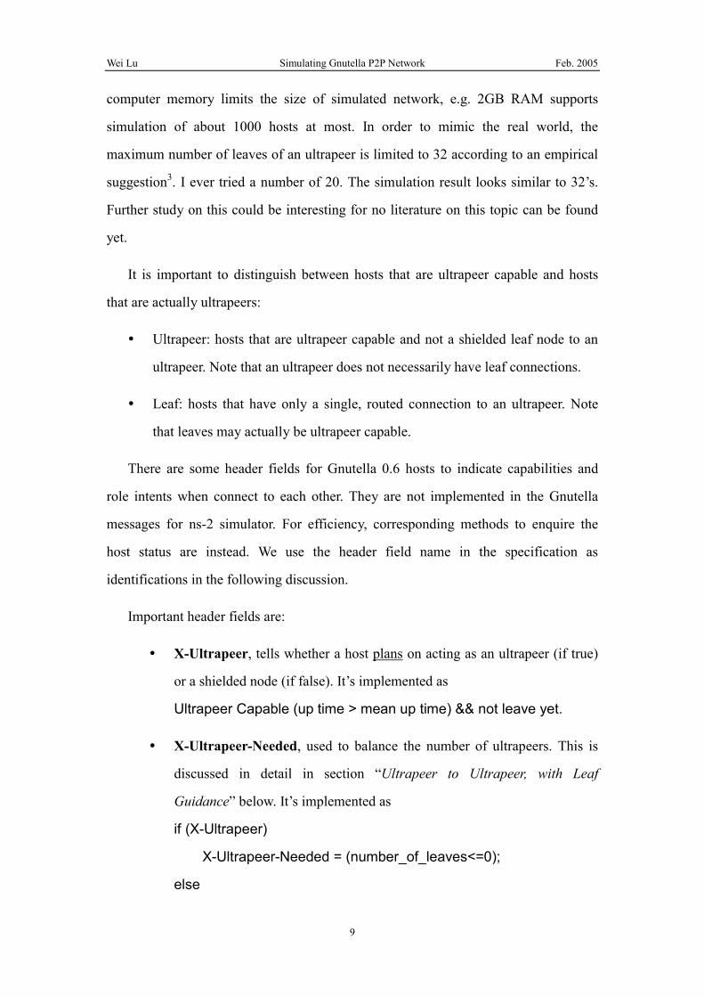
Leaf to Unshielded Leaf
Client Server
X-Ultrapeer: False
X-Ultrapeer: False
X-Ultrapeer-Needed: true
Sometimes nodes will be ultrapeer-incapable and unable to find an ultrapeer. In
this case, they behave exactly like old, unrouted Gnutella 0.4 connections.
Ultrapeer to Ultrapeer
Client Server
X-Ultrapeer: True
X-Ultrapeer-Needed: false
X-Ultrapeer: True
X-Ultrapeer-Needed: false
When two ultrapeers meet, both set X-Ultrapeer to true. If both have leaf nodes,
they will remain ultrapeer mode after the interaction.
Ultrapeer to Ultrapeer, with Leaf Guidance
Client (A) Server (B)
X-Ultrapeer: True
X-Ultrapeer-Needed: true
X-Ultrapeer: True
X-Ultrapeer-Needed: false
Consider the case of an ultrapeer, A connecting to an ultrapeer B, or the opposite.
A’s X-Ultrapeer-Needed is false, B’s X-Ultrapeer-Needed is true. X-Ultrapeer-Needed
Wei Lu Simulating Gnutella P2P Network Feb. 2005
12
indicates if host has no leaves currently. The one who has no leaves will become leaf
node of the other. When both already have leaves, the client becomes leaf of server
and drops original connections. Its previous leaves become unshielded nodes. When
the one chosen to be ultrapeer has already too many leaves, both peers remain
ultrapeer mode and the connection is established.
2.2 Message Dispatching
In Gnutella 0.4, Ping messages are flooded to every connected host. In Gnutella
0.6 implementation, leaf node will not send Ping message to other hosts except its
shielding ultrapeer. Ultrapeer only dispatches Ping message to other connected
ultrapeers.
2.3 Query Routing
In our Gnutella 0.6 implementation, leaf node will never spread Query message.
Ultrapeer only dispatches Query message to his leaf nodes that definitely have a
match to the query. This is a little different to the actual situation because the query
routing algorithm can never be 100% precise. And the simulation code checks the
database of leaf nodes to know if they have matched files. This process can be done
by C/C++ function invoking without actually generating network traffic. This part of
network traffic between ultrapeer and leaf nodes is ignored because it should be a
very little portion.
Wei Lu Simulating Gnutella P2P Network Feb. 2005
13
3 Implementation
We have implemented Gnutella 0.4 and Gnutella 0.6 protocol for ns-24 network
simulator and Ptolemy5 multi-purpose simulator framework. Both simulators provide
an open source Object-Oriented framework in C++ to be extended by sub-classing in
C++. Comparing to commercial simulation solutions like OPNET6, ns-2 and Ptolemy
are lack of ready-for-use result processing and analyzing functionalities. Quite a lot
post simulation processing scripts in Perl, Bash and Matlab are written in our work.
3.1 ns-2
3.1.1 ns-2 Introduction
Ns-2 simulator is a rich featured, well tuned and widely accepted discrete event
simulator for communication network research. It’s equipped with a well designed
heap based event scheduler that is very suitable for handling huge amount of events in
complex simulations. Its Object-Oriented architecture in C++ and scripting interface
in TCL make it easy to extend new functions. Further more, it includes a fully
implemented TCP/IP stack which is rarely seen in other simulation tools. This is of
great help for our work.
Figure 4, Runtime object layout of a simple simulation.
Wei Lu Simulating Gnutella P2P Network Feb. 2005
14
The internal structure of ns-2 is depicted as above. The bi-directional arrows
represent the flow of the control messages. The thick unilateral arrows are the data
flow between software objects. The thin unilateral arrows represent the virtual
simulated network transmission path.
In every simulation task, there is only one global Simulator object. It controls the
whole simulation. Class Application is the representation of the application layer of
the network. It generates the traffic and consumes it. Classes Agent is the
representation of the protocol stack. It can be understood as the protocol software in
the hosts. Class Node is the presentation of physical network nodes, e.g. networked
computer, switch, router, etc. Link presents the physical network link with packet
queues.
Simulation scenario is described by TCL scripts. Main program of ns-2 is
implemented as a TCL interpreter indeed. The interested metrics in the simulation can
be recorded by tracing packet events in Links and state variable changes in Agents
and saved to disk. Customer extensions can of course record their own information in
any ways. For example, our Gnutella protocol implementation outputs internal state
information to standard output and redirect to a text file for post analysis.
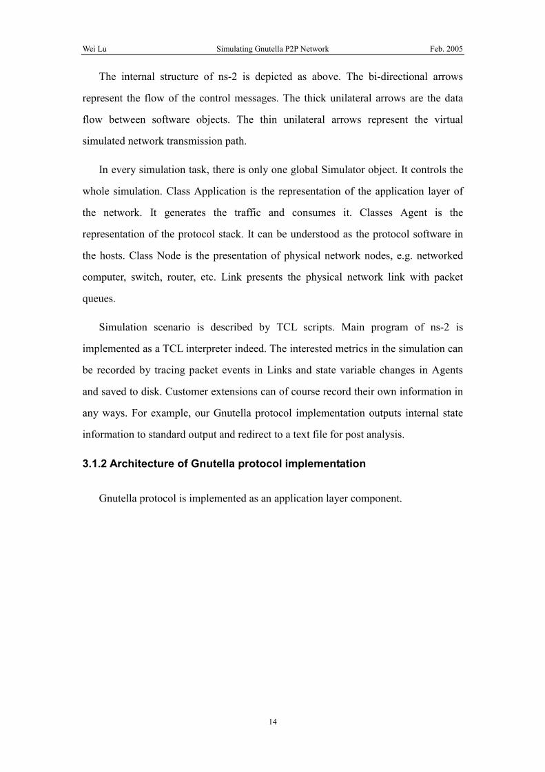
3.1.2 Architecture of Gnutella protocol implementation
Gnutella protocol is implemented as an application layer component.
Wei Lu Simulating Gnutella P2P Network Feb. 2005
15
Figure 5, UML of main classes of Gnutella protocol implementation
It’s a bit uncommon that GnutellaApp is not implemented as a child class of ns-2
Application class like what usual ns-2 extension does. The main reason is that the
TcpAgent is not created in TCL simulation setup script for each Application as usual.
Each GnutellaApp maintains multiple GnutellaConnection objects and the latter
maintains TcpAgent objects those are created dynamically in runtime to represent
multiple TCP connections. GnutellaApp still extends TclObject to be created in setup
scripts. GnutellaServent concretely implements the Gnutella protocol and invoked by
GnutellaApp when packet event is received. GnutellaGlobalRegisterationOffice is a
singleton helper class to generate shared file related random parameters.
Another unusual point is that Gnutella Message is not implemented as ns-2 Packet
and delivered in simulation events. Each GnutellaApp contains a local message list.
The message receiver can get the pointer of sender GnutellaApp via message
incoming GnutellaConnection and its Node pointer and then Node’s app_ pointer. The
receiver can access the sender GnutellaApp’s local message list to get the message
content directly. The original ns-2 Node class has to be modified to add pointer to
GnutellaApp object. This is not a neat solution but gives better performance. Another
disadvantage is that standard ns-2 tracing mechanism can not apply on Gnutella
Message statistic because message content is not transmitted in the simulation at all.
Wei Lu Simulating Gnutella P2P Network Feb. 2005
16
In GnutellaServent class, information about Gnutella protocol state and message
transmission is output to stdout with one second interval. We can execute the
simulation and redirect the output to a text file for post-processing. Some of the
post-processing scripts will be discussed later.
Differences between Gnutella 0.4 and Gnutella 0.6 mainly exist in message
receiving and relaying routines. Two versions can be selected by conditional
compiling option GNUTELLA_V06. Download traffic is injected by invoking TCL
scripts inside C++ codes after receive a QueryHit message.
3.2 Ptolemy
Ns-2 is very suitable for background the batch execution with a high efficient
scripting interface. However, there is a disadvantage that it has no interactive graphic
interface. Only an animation program for replaying finished simulation is provided.
This gives not much help for simulation scenario creation and debug.
Ptolemy is another simulation framework including discrete event scheme. An
interactive GUI is supported by Ptolemy. And the communication networks
department in TUHH developed a simple TCP/IP stack and other protocol
implementations for it. It’s valuable to port the Gnutella protocol to Ptolemy too.
With an adaptor pattern, Gnutella implementation can be compiled with Ptolemy
without modification to major part of the source code
The following figure depicts the over architecture of the Gnutella protocol in
Ptolemy.
Wei Lu Simulating Gnutella P2P Network Feb. 2005
17
Figure 6, Architecture of Gnutella on Ptolemy
There are some difficulties for the implementation.
Firstly, the scheduling and event mechanism is quite different between two
simulators. In ns-2, there is only one central schedule controlling the simulation. It’s a
Singleton pattern7 and can be accessed by static method like Scheduler::instance(). In
Ptolemy, every Star (basic simulation element in Ptolemy concept) may have a
scheduler because it may belong to different Domains in which the scheduling scheme
can be different. The current solution is to assign the pointer of the scheduler
belonging to current Star to a static variable to be accessed. This is just a temporal
solution before we find a better way.
Secondly, the timer required by the protocol is supported by scheduler in discrete
event simulation. We implement it in Ptolemy by sub-classing from DERepeatStar
that has a feedback wire to itself to implement a self-timer periodically. A sequence
diagram for this scenario can be represented as follows.
Wei Lu Simulating Gnutella P2P Network Feb. 2005
18
Figure 7, Sequence Diagram of Timer handling on Ptolemy port.
Figure 8, UML class diagram of main classes of Ptolemy port
DEGnutellaServent (DEGnutellaServent.pl) and DETCPMultiSocket
(DETCPMultiSocket.pl) are two new Ptolemy Stars. Every DETCPMultiSocket can
handle multiple active opened connections and multiple passive opened connections
at one server port. The connections_ is an array of TCPSocket class containing the
pointer of active opened TCP connections, except the last item points to a passively
opened server port listening for client connections. The array index is the local port of
the connection. The passively opened TCP connections are maintained in a map
serverConns as values. The keys are the remote address and remote port pairs. A 64
Wei Lu Simulating Gnutella P2P Network Feb. 2005
19
bit integer array remoteAddrPorts is used to allocate IDs for passive opened
connections. The index is the ID value. When the item value is 0, the ID is not
allocated, when the value is the remote address and remote port pair, the index is
allocated as the ID for corresponding connection. DEGnutellaServent is a Ptolemy
operational component (Star in Ptolemy concepts) as proxy of the concrete
implementation of Gnutella protocol, GnutellaServent (gnutella_protocol.cc/.h)
GnutellaApp (gnutella_app.cc/.h) is the interface connecting DEGnutellaServent
and GnutellaServent. In ns-2 simulator, it’s application layer representation and
attaches to Agent. The reason why this class still exists in Ptolemy implementation is
to provide an identical interface for GnutellaServent. Eventually, the
DEGnutellaServent Star will implement the interface of GnutellaApp and expose to
GnutellaServent. The GnutellaApp will be removed to save memory.
Main logic of Gnutella protocol exists in GnutellaServent. This class can be
compiled in both ns-2 and Ptolemy without specific modification. To achieve this, the
ns-2 classes those are used by GnutellaServent are re-implemented with the facility of
Ptolemy, e.g. Node, Scheduler, TimerHandler, etc.
3.3 Simulation setup and data process scripts
3.2.1 Simulation setup
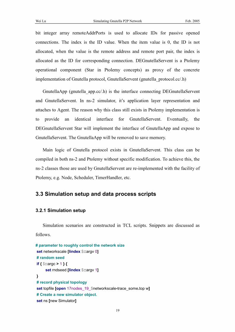
Simulation scenarios are constructed in TCL scripts. Snippets are discussed as
follows.
# parameter to roughly control the network size set networkscale [lindex $::argv 0] # random seed if { $::argc > 1 } { set rndseed [lindex $::argv 1] } # record physical topology set topfile [open 17nodes_19_$networkscale-trace_some.top w] # Create a new simulator object. set ns [new Simulator]
Wei Lu Simulating Gnutella P2P Network Feb. 2005
20
# Heap scheduler is high efficient in complex simulation $ns use-scheduler Heap # Create wired core nodes. set node(1) [$ns node] set node(2) [$ns node] #... set node(17) [$ns node] # Create links between nodes. $ns simplex-link $node(17) $node(16) 1000.000Mb 20.000000ms DropTail $ns simplex-link-op $node(17) $node(16) queuePos 0.5 $ns simplex-link-op $node(17) $node(16) color black $ns simplex-link-op $node(17) $node(16) orient 108.9deg # Set Queue Properties for link 17->16 [[$ns link $node(17) $node(16)] queue] set limit_ 500 $ns simplex-link $node(16) $node(17) 1000.000Mb 20.000000ms DropTail $ns simplex-link-op $node(16) $node(17) queuePos 0.5 $ns simplex-link-op $node(16) $node(17) color black $ns simplex-link-op $node(16) $node(17) orient 288.9deg # Set Queue Properties for link 16->17 [[$ns link $node(16) $node(17)] queue] set limit_ 500 # ... $ns simplex-link $node(2) $node(1) 1000.000Mb 20.000000ms DropTail $ns simplex-link-op $node(2) $node(1) queuePos 0.5 $ns simplex-link-op $node(2) $node(1) color black $ns simplex-link-op $node(2) $node(1) orient 87.9deg # Set Queue Properties for link 2->1 [[$ns link $node(2) $node(1)] queue] set limit_ 500 $ns simplex-link $node(1) $node(2) 1000.000Mb 20.000000ms DropTail $ns simplex-link-op $node(1) $node(2) queuePos 0.5 $ns simplex-link-op $node(1) $node(2) color black $ns simplex-link-op $node(1) $node(2) orient 267.9deg # Set Queue Properties for link 1->2 [[$ns link $node(1) $node(2)] queue] set limit_ 500 #setup trace on links set trfile25 [open 17nodes_19_$networkscale-trace_some_1-3.tr w] $ns trace-queue $node(1) $node(3) $trfile25 set trfile26 [open 17nodes_19_$networkscale-trace_some_1-2.tr w] $ns trace-queue $node(1) $node(2) $trfile26 set trfiler25 [open 17nodes_19_$networkscale-trace_some_r1-3.tr w] $ns trace-queue $node(3) $node(1) $trfiler25 set trfiler26 [open 17nodes_19_$networkscale-trace_some_r1-2.tr w] $ns trace-queue $node(2) $node(1) $trfiler26
Wei Lu Simulating Gnutella P2P Network Feb. 2005
21
# set up the Gnutella Global office set go [new GnutellaGlobalRegistrationOffice] if { $::argc > 1 } { $go seed $rndseed puts "\tINFO:set seed to $rndseed\n" } else { $go seed 32145 } # load emperical file size distribution $go readFile gnutella/gnutella.files # To implement the second layer of topology, implement power-law distribution set u [new RandomVariable/Pareto] $u set avg_ $networkscale $u set shape_ 1.5 # Initialize a general uniform variable to randomly select access link speed set uniform [new RandomVariable/Uniform] $uniform set min_ 0 $uniform set max_ 1 # The following loop implements the 2nd layer of the heirarchy. The number of nodes per core-node is power-law distributed, the power is controlled with the shape parameter set counter 18 set counter2 1 set appcounter 1 set numConnections 0 for {set x 1} {$x <= 17} {incr x} { puts "node([expr ($x) ]).[$node([expr ($x) ]) address?] link to:" set z [expr round([$u value])] for {set y 1} {$y <= $z} {incr y} { set node([expr ($counter)]) [$ns node] puts " node([expr ($counter)]).[$node([expr ($counter)]) address?]" set emp [expr [$uniform value]] # monitor specific MODEM and DSL user if {$counter == 18} { set userSpeed 100.000kb set numConnections 12 } else { if {$counter == 22} { set userSpeed 1.000Mb set numConnections 30 } else { if {$emp <= 0.70 } { set userSpeed 100.000kb
Wei Lu Simulating Gnutella P2P Network Feb. 2005
22
set numConnections 12 } else { if {$emp <= 0.94 } { set userSpeed 1.000Mb set numConnections 30 } else { if {$emp <= 0.985 } { set userSpeed 2.000Mb set numConnections 75 } else { if {$emp <= 0.996 } { set userSpeed 4.000Mb set numConnections 120 } else { if {$emp <= 1.000 } { set userSpeed 1000.000Mb set numConnections 800 } }}}}}} # set up the link $ns duplex-link $node($x) $node([expr ($counter)]) $userSpeed 20.000000ms DropTail puts " link node([expr ($x)]).[$node([expr ($x) ]) address?] and node([expr ($counter)]).[$node([expr ($counter)]) address?] with delay $userSpeed" # Set Queue Properties for the link with QueueSize = 500 [[$ns link $node($x) $node([expr ($counter)])] queue] set limit_ 500 # Attach GnutellaApp agent set app([expr ($appcounter)]) [new GnutellaApp $node([expr ($counter)]) $numConnections $go] if {$numConnections > 120} { $go regBootStrapServent $node([expr ($counter)]) puts " app([expr ($appcounter)]) registered for bootstrap" puts $topfile "[$node([expr ($counter)]) address?] 1 bootstrap [$node([expr ($x) ]) address?]" } else { if {$numConnections<=12} { puts $topfile "[$node([expr ($counter)]) address?] 3 modem [$node([expr ($x) ]) address?]" } else { puts $topfile "[$node([expr ($counter)]) address?] 2 DSL [$node([expr ($x) ]) address?]" } }
Wei Lu Simulating Gnutella P2P Network Feb. 2005
23
# monitor selected MODEM and DSL user if {$counter == 18} { set trmodem [open 17nodes_19_$networkscale-trace_some_r1-$counter-modem.tr w] $ns trace-queue $node($counter) $node(1) $trmodem $app($appcounter) monitor-this #$app($appcounter) set-min-on 100000 } else { if {$counter == 22} { set trdsl [open 17nodes_19_$networkscale-trace_some_r1-$counter-dsl.tr w] $ns trace-queue $node($counter) $node(1) $trdsl $app($appcounter) monitor-this #$app($appcounter) set-min-on 100000 } } incr counter incr appcounter } } close $topfile for {set a 1} {$a < $appcounter} {incr a} { # Traffic with download or singlaing only $app($a) enable-download # Start Gnutella protocol $ns at [expr (0)] "$app($a) start" } # clean up routine when simulation complete proc finish {} { $ns flush-trace close $trfile25 close $trfile26 close $trfiler25 close $trfiler26 exit 0 } # Run the simulation $ns at 500.00010 "finish" $ns run
List 1, Simulation setup script
Wei Lu Simulating Gnutella P2P Network Feb. 2005
24
3.3.2 Data processing
There are 3 sources of data to be processed after simulation to get interested
metrics. As we can see in List 1, Simulation setup script, physical topology
information including access speed, linkages, etc. is output to stdout by TCL
statements. GnutellaServent outputs the internal state information including counts of
sent messages, number of opened connections, etc., to stdout. We capture these two
sources into text file by output redirection in command line. The 3rd type of trace data
is recorded by Link trace supported by ns-2 build-in function, as we can see in above
“ $ns trace-queue” statements.
Physical topology information is used to calculate traffic rates of given access
type. Gnutella internal states can be used to calculate traffic metrics in message level.
Awk is used to filter the desired columns of data, like the following command: