Interview with Travis Hunter of Graham Packaging SIMULATION IN ACTION FINDING THE SOLUTION TO A NOISE PROBLEM VTT Technical Research Center Solves vibro-acoustic problems EXTENDING THE LIFE OF SUBSEA DRILLING EQUIPMENT 4Subsea AS relies on simulation for accurate part life predictions ACCURATE SIMULATION OF COMPLEX VEHICLE SYSTEM DYNAMICS Interview with Stefano Cassara, Navistar, Inc. MSC Software Magazine | Volume IV | Summer 2014 Issue
Transcript
Interview with Travis Hunter of Graham PackagingSIMULATION IN ACTION
FINDING THE SOLUTION TO A NOISE PROBLEMVTT Technical Research Center Solves vibro-acoustic problems
EXTENDING THE LIFE OF SUBSEA DRILLING EQUIPMENT4Subsea AS relies on simulation for accurate part life predictions
ACCURATE SIMULATION OF COMPLEX VEHICLE SYSTEM DYNAMICSInterview with Stefano Cassara, Navistar, Inc.
MSC Software Magazine | Volume IV | Summer 2014 Issue
NVIDIA® TESLA® K20ACCELERATE YOUR MSC APPLICATIONS WITH THE HP GPU STARTER KIT.
Need a GPU cluster but don’t know where to go? HP and NVIDIA have collaborated to develop the HP GPU Starter Kit, an entry-level, pre-configured GPU cluster bundle that is based on HP ProLiant SL250s Gen8 servers with integrated NVIDIA Tesla K20 GPUs. Everything you need to get started with a GPU cluster in one, easy-to-use package.
For more information on the HP GPU Starter Kit:Email: [email protected]
8Multibody Dynamics - A “Market Opportunity” For Higher Education
PRODUCT NEWS IN-BRIEF
10Manage Your Materials Data
MSC IN THE NEWS
12Simulation News & Media Coverage
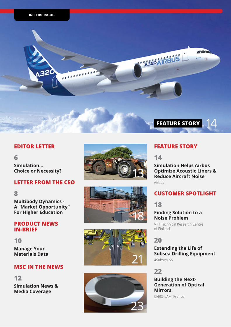
FEATURE STORY
14Simulation Helps Airbus Optimize Acoustic Liners & Reduce Aircraft NoiseAirbus
CUSTOMER SPOTLIGHT
18Finding Solution to a Noise ProblemVTT Technical Research Centre of Finland
20Extending the Life of Subsea Drilling Equipment4Subsea AS
22Building the Next-Generation of Optical MirrorsCNRS-LAM, France
FEATURE STORY
EC Engineering Sp. z o.o. from Poland is one of the fastest growing design and development office in Europe. The company gained a status of a Research and Development Centre in 2009. We employ over 250 well-‐trained engineers. They parCcipate in design and development of high-‐speed trains in Germany, Italy, China, as well as other vehicles in countries like Austria, Belgium, France, Netherlands, Czech Republic, Romania and Japan. Every year we increase our expansion on internaConal markets; currently our business is focused on the Asian area. Thanks to long-‐term cooperaCon with the leading company in producCon of rail vehicles, the Bombardier TransportaCon, we parCcipate in preparatory design works of ZEFIRO high-‐speed trains. Since 2004 we have also been involved in many projects related to aviaCon industry-‐including such engineering projects as – Airbus A380 and Airbus A350. Since 2010 we have been also engaged in manufacturing projects. Our first leading product is the 160EC pantograph, designed by the EC Engineering specialist. The breakthrough moment was merging of our capabiliCes with WSK PZL Mielec. The tooling company became a part of EC Grupa in May 2012 and now acCng as ProducCon Site – Mielec EC Engineering Company. Since then we have also been a major manufacturer of tooling and instrumentaCon, and we started batch producCon.
Your Bridge To The World Of Modern Technologies
Main departments of our company:
Railway AviaCon
AutomoCve So^ware
ProducCon
since 1998
EC Engineering Sp. z o.o.
is an authorized representaCve of CAE simulaCon so^ware vendors (Computer Aided Engineering) in
26Patran: Useful Group ToolsChristian Aparicio, MSC Software
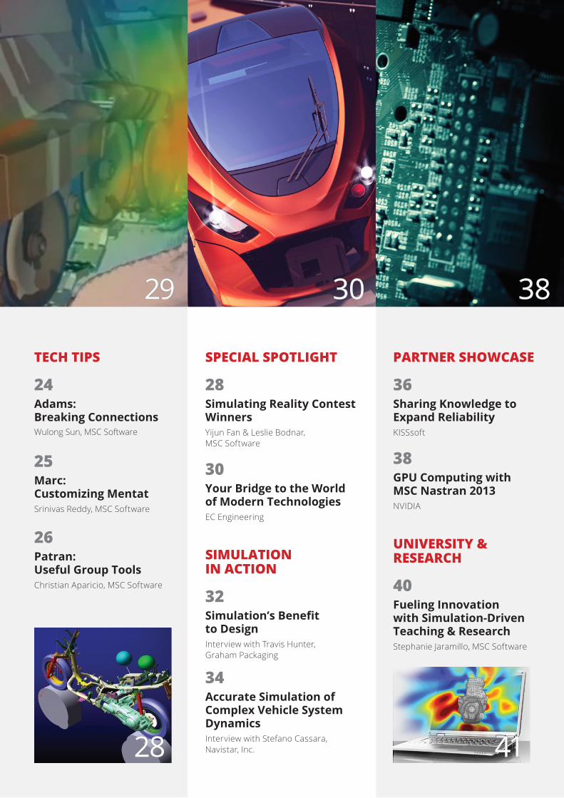
SPECIAL SPOTLIGHT
28Simulating Reality Contest WinnersYijun Fan & Leslie Bodnar,MSC Software
30Your Bridge to the World of Modern TechnologiesEC Engineering
SIMULATION IN ACTION
32Simulation’s Benefit to DesignInterview with Travis Hunter,Graham Packaging
34Accurate Simulation of Complex Vehicle System DynamicsInterview with Stefano Cassara,Navistar, Inc.
PARTNER SHOWCASE
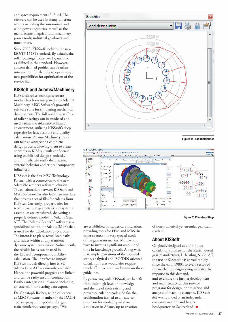
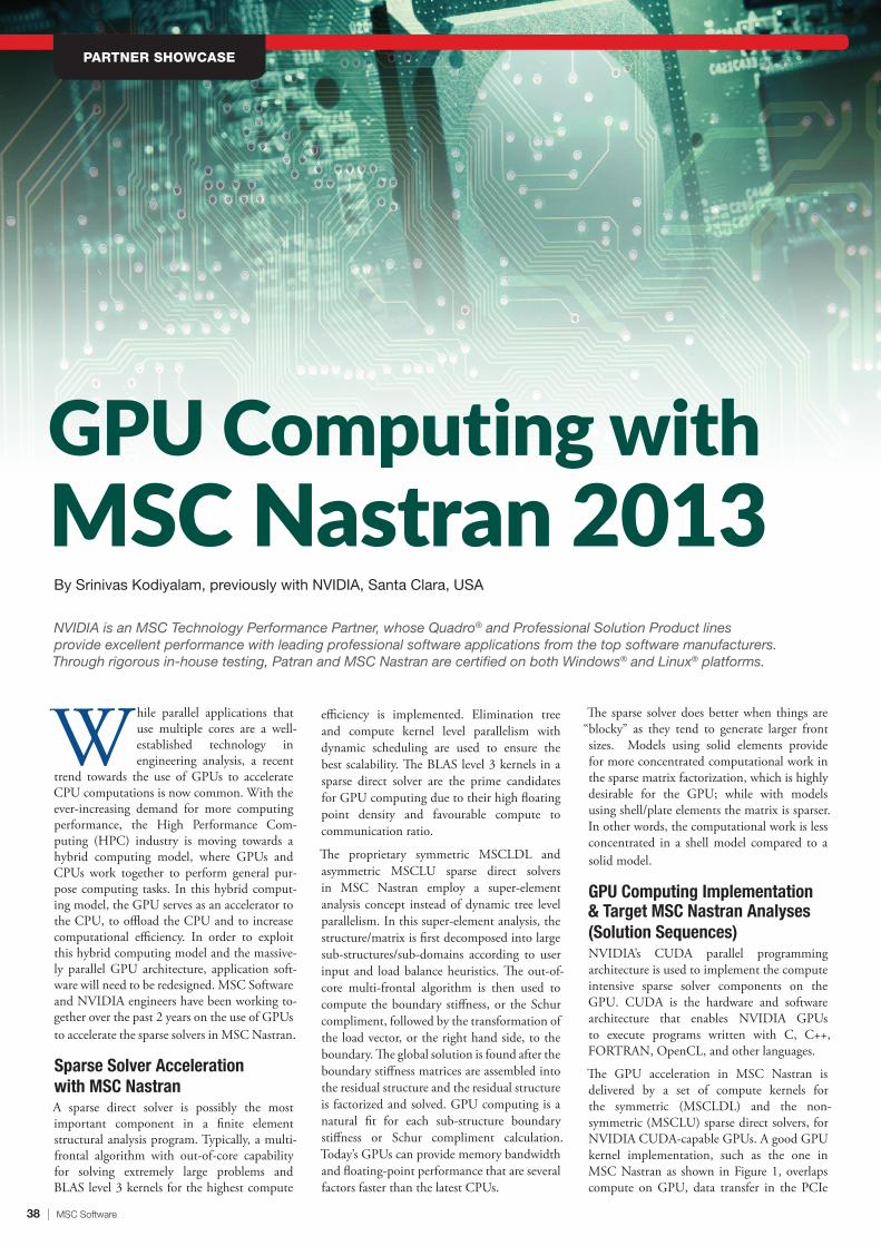
36Sharing Knowledge to Expand ReliabilityKISSsoft
38GPU Computing with MSC Nastran 2013NVIDIA
UNIVERSITY & RESEARCH
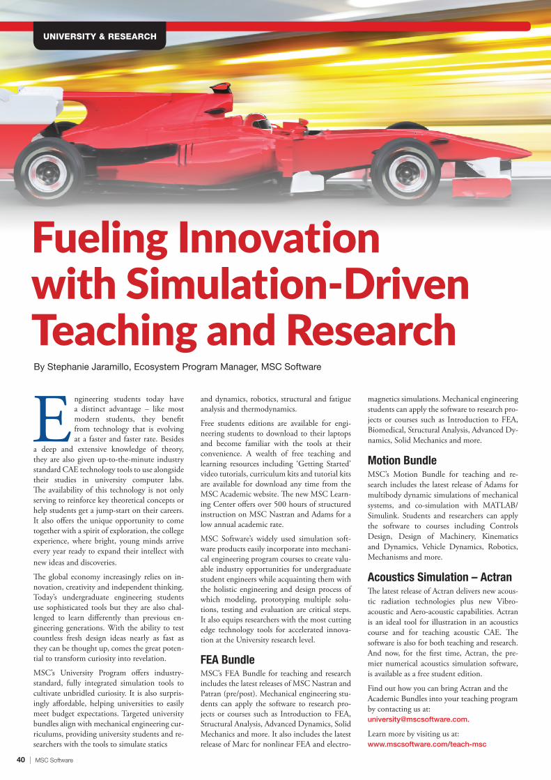
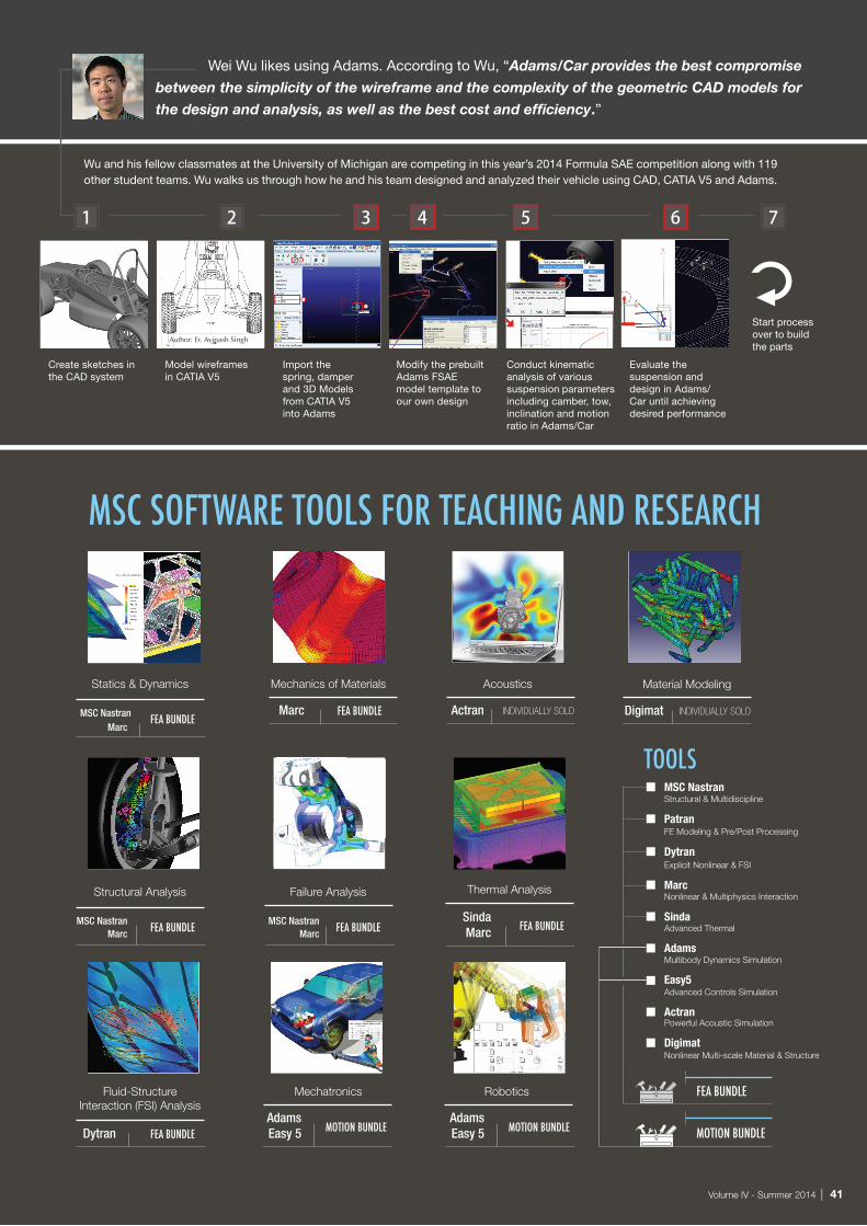
40Fueling Innovation with Simulation-Driven Teaching & ResearchStephanie Jaramillo, MSC Software
Best practice design teams use high performance file-based shared storage to optimize manufacturing research and maximize design time. Fast access to shared files makes the work of simulation experts, product analysts, design engineers and verification and certification teams more efficient.
Panasas® ActiveStor® scale-out NAS products with the integrated PanFS® parallel file system balance ease-of-use, extreme performance, scalable capacity and work-load flexibility to deliver an ideal solution for CAE environments. Panasas DataRunner™ high perfor-mance file transfer software accelerates file sharing between sites to boost collaboration.
PANA SA S ACTIVESTORTHE WORLD’S FASTEST PARALLEL STORAGE SOLUTION
E D A S I M U L AT I O N | T H E R M A L M E C H A N I C S | C F D | F E A | O P T I C A L C O R R E C T I O N | M O D E L I N G
1.888.PANASAS | www.panasas.com
Shared parallel data access
Linear scaling to 150GB/s, or 1.4M IOPS
SSD + SATA for best price/performance
Optimized for mixed file size workloads
Quick to install, easy to manage
By shortening time-to-design and eliminating expensive physical modeling with high fidelity, computer-aided simulation, Panasas customers realize compelling cost benefits. In addition, by delivering a highly reliable, high performance storage platform, Panasas ensures that engineers and scientists can focus on creating value, rather than on system administration.
• Only 30% are satisfied with the MBD education that university is providing.
So, what is going on in academia and what is required? Kinematics and dynamics courses are taught as part of core undergraduate engineering curriculum helping provide the required foundation in mechanics for the students. However, students are rarely exposed to the computational modeling and simulation software solutions used by practicing engineers, and are typically limited to simplified tools. Further, multibody system dynamics simulation is not hard once you know the basics of kinematics and dynamics. Schools need to have more emphasis on engineering math and classical dynamics, vibration and control theory course work to understand the theory. Of course, the best kind of training is on the job training with respect to products that matter to engineers, as opposed to generic classroom training. This offers a wonderful opportunity for universities to create internships with manufacturers that are starved for this skill.
Lett
er f
rom
the
CE
O In talking to many customers over the years, I could feel a real desperation in filling positions that require multibody dynamics (MBD) skills. Equally, I sensed the
same frustration from professors in higher education who have trouble attracting students to their dynamics classes. Why? Because there is an impression that Computer Aided Engineering (CAE) equals Finite Element Analysis (FEA). So, academia is producing a steady crop of graduates who are well versed in FEA but because of the lack of understanding of the market need, graduates skilled in MBD are scarce.
To better quantify the market need, we surveyed our users recently. 73% of the users were either from auto or aero OEMs or their suppliers. The results are not surprising.
• 40% said that the amount of multibody simulations will grow 2-5X in the next few years.
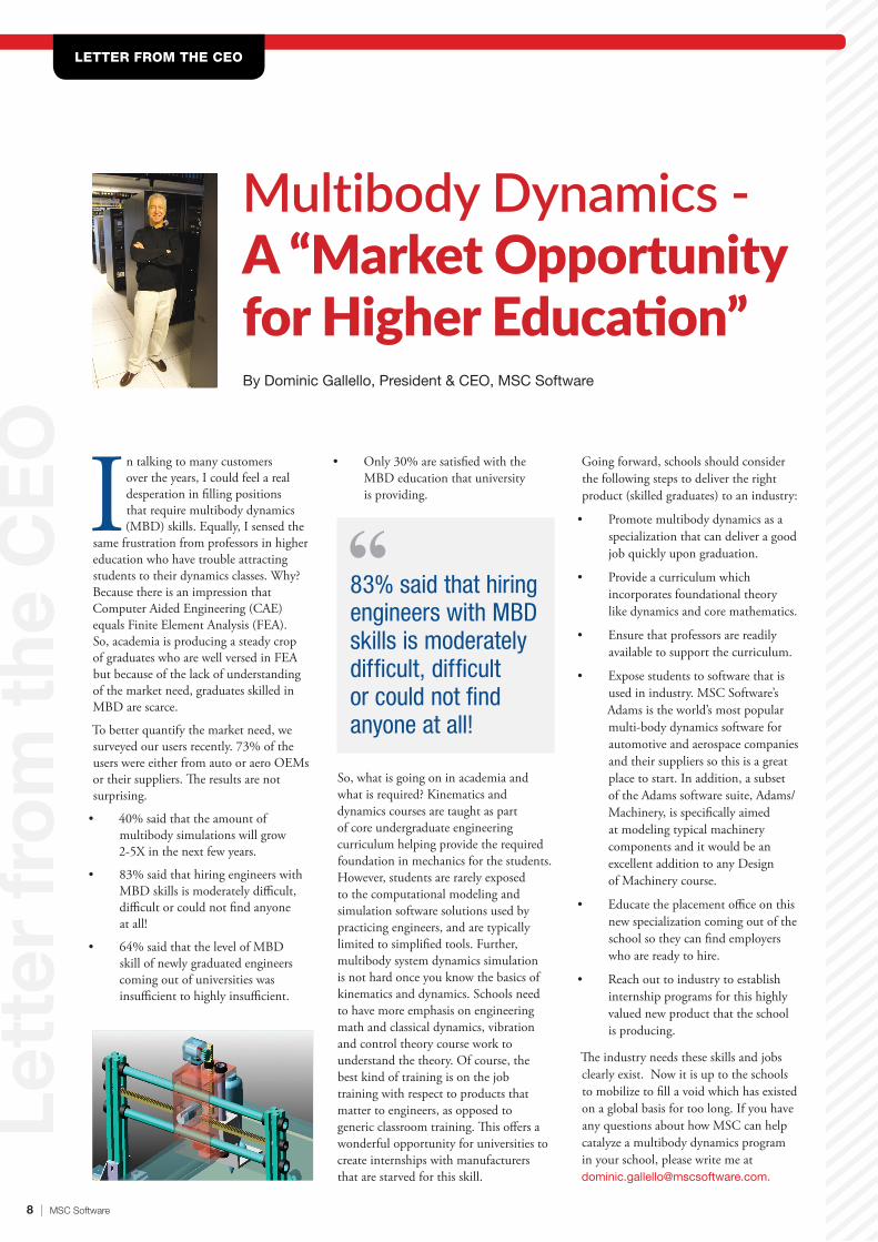
• 83% said that hiring engineers with MBD skills is moderately difficult, difficult or could not find anyone at all!
• 64% said that the level of MBD skill of newly graduated engineers coming out of universities was insufficient to highly insufficient.
Multibody Dynamics -A “Market Opportunity for Higher Education”By Dominic Gallello, President & CEO, MSC Software
Going forward, schools should consider the following steps to deliver the right product (skilled graduates) to an industry:
• Promote multibody dynamics as a specialization that can deliver a good job quickly upon graduation.
• Provide a curriculum which incorporates foundational theory like dynamics and core mathematics.
• Ensure that professors are readily available to support the curriculum.
• Expose students to software that is used in industry. MSC Software’s Adams is the world’s most popular multi-body dynamics software for automotive and aerospace companies and their suppliers so this is a great place to start. In addition, a subset of the Adams software suite, Adams/Machinery, is specifically aimed at modeling typical machinery components and it would be an excellent addition to any Design of Machinery course.
• Educate the placement office on this new specialization coming out of the school so they can find employers who are ready to hire.
• Reach out to industry to establish internship programs for this highly valued new product that the school is producing.
The industry needs these skills and jobs clearly exist. Now it is up to the schools to mobilize to fill a void which has existed on a global basis for too long. If you have any questions about how MSC can help catalyze a multibody dynamics program in your school, please write me at [email protected].
LETTER FROM THE CEO
83% said that hiring engineers with MBD skills is moderately difficult, difficult or could not find anyone at all!
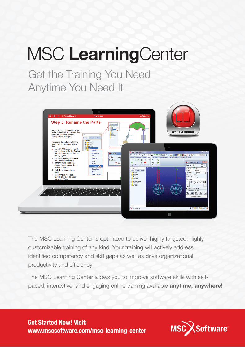
Get the Training You NeedAnytime You Need It
The MSC Learning Center is optimized to deliver highly targeted, highly
customizable training of any kind. Your training will actively address
identified competency and skill gaps as well as drive organizational
productivity and efficiency.
The MSC Learning Center allows you to improve software skills with self-
paced, interactive, and engaging online training available anytime, anywhere!
Get Started Now! Visit: www.mscsoftware.com/msc-learning-center
10 | MSC Software
MSC UPDATE & NEWSPRODUCT NEWS IN-BRIEF
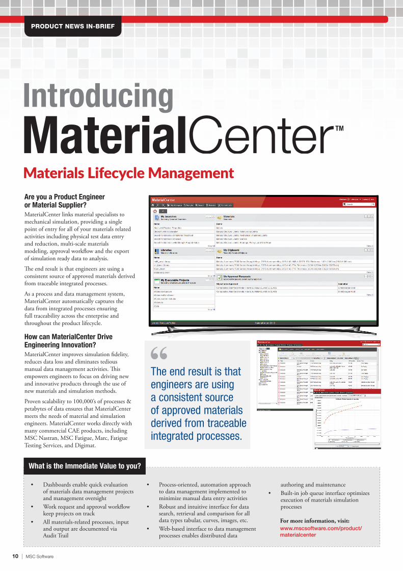
Introducing
Materials Lifecycle Management Are you a Product Engineer or Material Supplier?MaterialCenter links material specialists to mechanical simulation, providing a single point of entry for all of your materials related activities including physical test data entry and reduction, multi-scale materials modeling, approval workflow and the export of simulation ready data to analysis.
The end result is that engineers are using a consistent source of approved materials derived from traceable integrated processes.
As a process and data management system, MaterialCenter automatically captures the data from integrated processes ensuring full traceability across the enterprise and throughout the product lifecycle.
How can MaterialCenter Drive Engineering Innovation? MaterialCenter improves simulation fidelity, reduces data loss and eliminates tedious manual data management activities. This empowers engineers to focus on driving new and innovative products through the use of new materials and simulation methods.
Proven scalability to 100,000’s of processes & petabytes of data ensures that MaterialCenter meets the needs of material and simulation engineers. MaterialCenter works directly with many commercial CAE products, including MSC Nastran, MSC Fatigue, Marc, Fatigue Testing Services, and Digimat.
What is the Immediate Value to you?
• Dashboards enable quick evaluation of materials data management projects and management oversight
• Work request and approval workflow keep projects on track
• All materials-related processes, input and output are documented via Audit Trail
• Process-oriented, automation approach to data management implemented to minimize manual data entry activities
• Robust and intuitive interface for data search, retrieval and comparison for all data types tabular, curves, images, etc.
• Web-based interface to data management processes enables distributed data
authoring and maintenance• Built-in job queue interface optimizes
execution of materials simulation processes
For more information, visit: www.mscsoftware.com/product/materialcenter
The end result is that engineers are using a consistent source of approved materials derived from traceable integrated processes.
MSC IN THE NEWS
12 | MSC Software
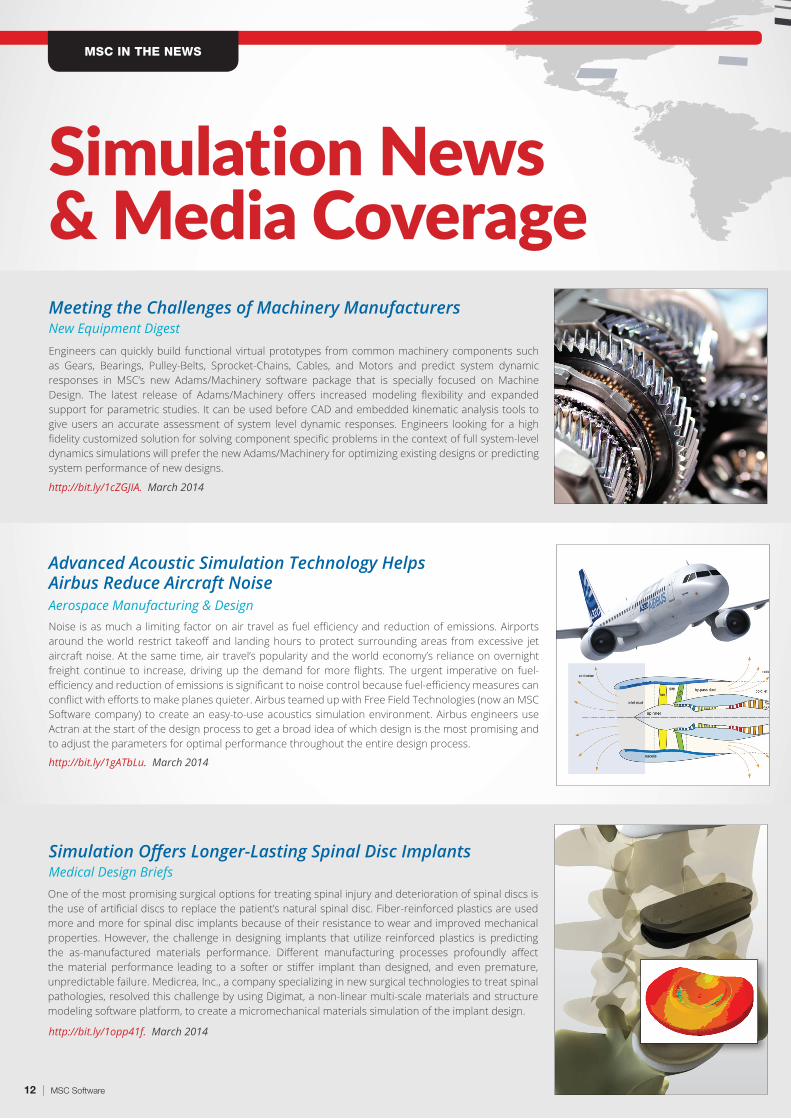
Engineers can quickly build functional virtual prototypes from common machinery components such as Gears, Bearings, Pulley-Belts, Sprocket-Chains, Cables, and Motors and predict system dynamic responses in MSC’s new Adams/Machinery software package that is specially focused on Machine Design. The latest release of Adams/Machinery offers increased modeling flexibility and expanded support for parametric studies. It can be used before CAD and embedded kinematic analysis tools to give users an accurate assessment of system level dynamic responses. Engineers looking for a high fidelity customized solution for solving component specific problems in the context of full system-level dynamics simulations will prefer the new Adams/Machinery for optimizing existing designs or predicting system performance of new designs.
Meeting the Challenges of Machinery ManufacturersNew Equipment Digest
http://bit.ly/1cZGJIA. March 2014
Noise is as much a limiting factor on air travel as fuel efficiency and reduction of emissions. Airports around the world restrict takeoff and landing hours to protect surrounding areas from excessive jet aircraft noise. At the same time, air travel’s popularity and the world economy’s reliance on overnight freight continue to increase, driving up the demand for more flights. The urgent imperative on fuel-efficiency and reduction of emissions is significant to noise control because fuel-efficiency measures can conflict with efforts to make planes quieter. Airbus teamed up with Free Field Technologies (now an MSC Software company) to create an easy-to-use acoustics simulation environment. Airbus engineers use Actran at the start of the design process to get a broad idea of which design is the most promising and to adjust the parameters for optimal performance throughout the entire design process.
One of the most promising surgical options for treating spinal injury and deterioration of spinal discs is the use of artificial discs to replace the patient’s natural spinal disc. Fiber-reinforced plastics are used more and more for spinal disc implants because of their resistance to wear and improved mechanical properties. However, the challenge in designing implants that utilize reinforced plastics is predicting the as-manufactured materials performance. Different manufacturing processes profoundly affect the material performance leading to a softer or stiffer implant than designed, and even premature, unpredictable failure. Medicrea, Inc., a company specializing in new surgical technologies to treat spinal pathologies, resolved this challenge by using Digimat, a non-linear multi-scale materials and structure modeling software platform, to create a micromechanical materials simulation of the implant design.
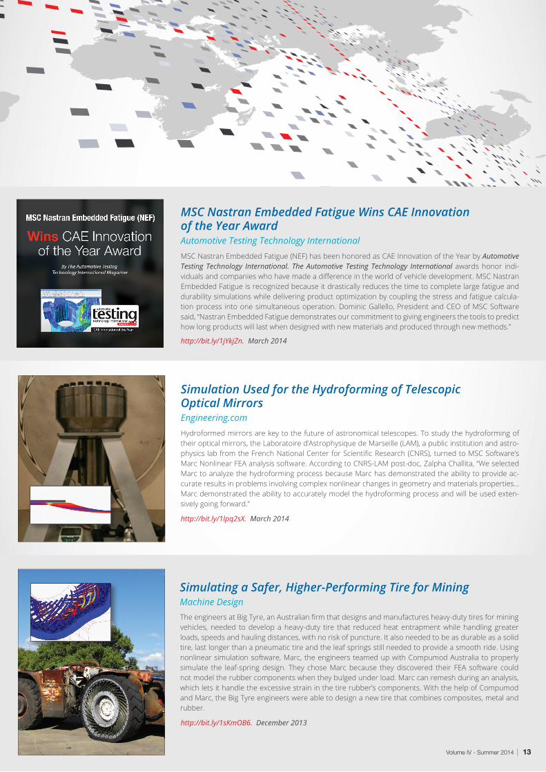
MSC Nastran Embedded Fatigue (NEF) has been honored as CAE Innovation of the Year by Automotive Testing Technology International. The Automotive Testing Technology International awards honor indi-viduals and companies who have made a difference in the world of vehicle development. MSC Nastran Embedded Fatigue is recognized because it drastically reduces the time to complete large fatigue and durability simulations while delivering product optimization by coupling the stress and fatigue calcula-tion process into one simultaneous operation. Dominic Gallello, President and CEO of MSC Software said, “Nastran Embedded Fatigue demonstrates our commitment to giving engineers the tools to predict how long products will last when designed with new materials and produced through new methods.”
MSC Nastran Embedded Fatigue Wins CAE Innovation of the Year AwardAutomotive Testing Technology International
http://bit.ly/1jYkjZn. March 2014
Hydroformed mirrors are key to the future of astronomical telescopes. To study the hydroforming of their optical mirrors, the Laboratoire d’Astrophysique de Marseille (LAM), a public institution and astro-physics lab from the French National Center for Scientific Research (CNRS), turned to MSC Software’s Marc Nonlinear FEA analysis software. According to CNRS-LAM post-doc, Zalpha Challita, “We selected Marc to analyze the hydroforming process because Marc has demonstrated the ability to provide ac-curate results in problems involving complex nonlinear changes in geometry and materials properties... Marc demonstrated the ability to accurately model the hydroforming process and will be used exten-sively going forward.”
Simulation Used for the Hydroforming of Telescopic Optical MirrorsEngineering.com
http://bit.ly/1lpq2sX. March 2014
The engineers at Big Tyre, an Australian firm that designs and manufactures heavy-duty tires for mining vehicles, needed to develop a heavy-duty tire that reduced heat entrapment while handling greater loads, speeds and hauling distances, with no risk of puncture. It also needed to be as durable as a solid tire, last longer than a pneumatic tire and the leaf springs still needed to provide a smooth ride. Using nonlinear simulation software, Marc, the engineers teamed up with Compumod Australia to properly simulate the leaf-spring design. They chose Marc because they discovered their FEA software could not model the rubber components when they bulged under load. Marc can remesh during an analysis, which lets it handle the excessive strain in the tire rubber’s components. With the help of Compumod and Marc, the Big Tyre engineers were able to design a new tire that combines composites, metal and rubber.
Simulating a Safer, Higher-Performing Tire for MiningMachine Design
http://bit.ly/1sKmOB6. December 2013
14 | MSC Software
Simulation Helps Airbus Optimize Acoustic Liners & Reduce Aircraft NoiseAirbus | Based on an interview with Jean-Yves Suratteau, Airbus
FEATURE STORY
QUIET, PLEASE.
Volume IV - Summer 2014 | 15
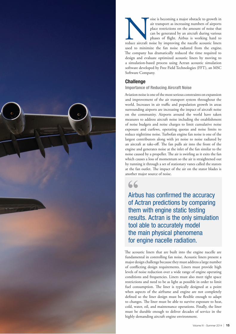
Noise is becoming a major obstacle to growth in air transport as increasing numbers of airports place restrictions on the amount of noise that can be generated by an aircraft during various phases of flight. Airbus is working hard to
reduce aircraft noise by improving the nacelle acoustic liners used to minimize the fan noise radiated from the engine. The company has dramatically reduced the time required to design and evaluate optimized acoustic liners by moving to a simulation-based process using Actran acoustic simulation software developed by Free Field Technologies (FFT), an MSC Software Company.
ChallengeImportance of Reducing Aircraft Noise
Aviation noise is one of the most serious constraints on expansion and improvement of the air transport system throughout the world. Increases in air traffic and population growth in areas surrounding airports are increasing the impact of aircraft noise on the community. Airports around the world have taken measures to address aircraft noise including the establishment of noise budgets and noise charges to limit cumulative noise exposure and curfews, operating quotas and noise limits to reduce nighttime noise. Turbofan engine fan noise is one of the largest contributors along with jet noise to noise radiated by an aircraft at take-off. The fan pulls air into the front of the engine and generates noise at the inlet of the fan similar to the noise caused by a propeller. The air is swirling as it exits the fan which causes a loss of momentum so the air is straightened out by running it through a set of stationary vanes called the stators at the fan outlet. The impact of the air on the stator blades is another major source of noise.
The acoustic liners that are built into the engine nacelle are fundamental in controlling fan noise. Acoustic liners present a major design challenge because they must address a large number of conflicting design requirements. Liners must provide high levels of noise reduction over a wide range of engine operating conditions and frequencies. Liners must also meet tight space restrictions and need to be as light as possible in order to limit fuel consumption. The liner is typically designed at a point when aspects of the airframe and engine are not completely defined so the liner design must be flexible enough to adapt to changes. The liner must be able to survive exposure to heat, cold, water, oil, and maintenance operations. Finally, the liner must be durable enough to deliver decades of service in the highly demanding aircraft engine environment.
Airbus has confirmed the accuracy of Actran predictions by comparing them with engine static testing results. Actran is the only simulation tool able to accurately model the main physical phenomena for engine nacelle radiation.
16 | MSC Software
SolutionImproving Acoustic Liner Design
Originally, the design of acoustic liners was based on static tests performed by running the engine on a test rig and measuring the radiated noise with an array of microphones. This approach was very expensive and design evaluation could not be initiated until a prototype engine was available for testing. To address this challenge, Airbus engineers used analytical tools that predicted noise radiation but these tools were only accurate when used with very simple geometries so their usefulness in modeling noise radiation from the nacelle was limited. Airbus has long been working to more accurately simulate noise radiation from the nacelle.
“When FFT created the Actran consortium in 1999, the Acoustic Department of Airbus-France decided to be part of it and to support the development of the first version of Actran software.
We are currently using it for design of nacelle liners in engine inlets and exhaust ducts, cockpit and cabin interior noise, air systems at ground, propellers and contra-rotating propellers,” Suratteau said. (Fig. 5) “Airbus has confirmed the accuracy of Actran predictions by comparing them with engine static testing results. Actran is the only simulation tool able to accurately model the main physical phenomena for engine nacelle radiation.”
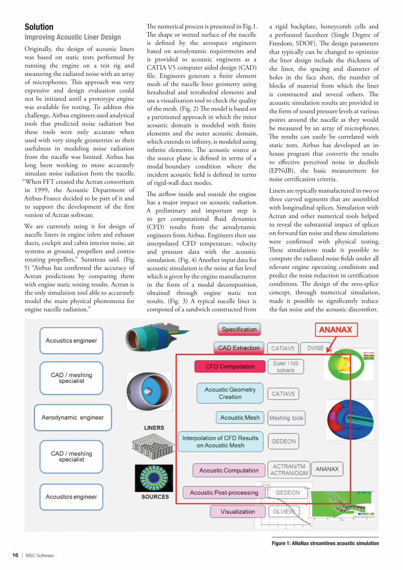
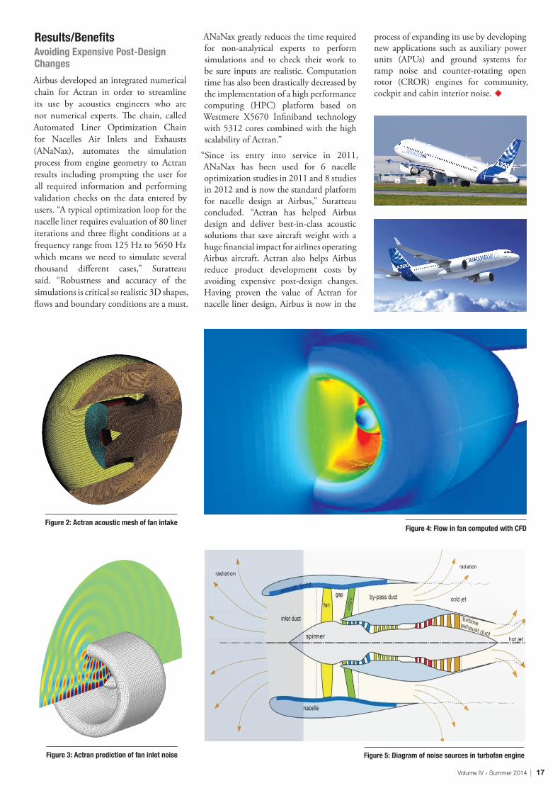
The numerical process is presented in Fig.1. The shape or wetted surface of the nacelle is defined by the aerospace engineers based on aerodynamic requirements and is provided to acoustic engineers as a CATIA V5 computer aided design (CAD) file. Engineers generate a finite element mesh of the nacelle liner geometry using hexahedral and tetrahedral elements and use a visualization tool to check the quality of the mesh. (Fig. 2) The model is based on a partitioned approach in which the inner acoustic domain is modeled with finite elements and the outer acoustic domain, which extends to infinity, is modeled using infinite elements. The acoustic source at the source plane is defined in terms of a modal boundary condition where the incident acoustic field is defined in terms of rigid-wall duct modes.
The airflow inside and outside the engine has a major impact on acoustic radiation. A preliminary and important step is to get computational fluid dynamics (CFD) results from the aerodynamic engineers from Airbus. Engineers then use interpolated CFD temperature, velocity and pressure data with the acoustic simulation. (Fig. 4) Another input data for acoustic simulation is the noise at fan level which is given by the engine manufacturers in the form of a modal decomposition, obtained through engine static test results. (Fig. 3) A typical nacelle liner is composed of a sandwich constructed from
a rigid backplate, honeycomb cells and a perforated facesheet (Single Degree of Freedom, SDOF). The design parameters that typically can be changed to optimize the liner design include the thickness of the liner, the spacing and diameter of holes in the face sheet, the number of blocks of material from which the liner is constructed and several others. The acoustic simulation results are provided in the form of sound pressure levels at various points around the nacelle as they would be measured by an array of microphones. The results can easily be correlated with static tests. Airbus has developed an in-house program that converts the results to effective perceived noise in decibels (EPNdB), the basic measurement for noise certification criteria.
Liners are typically manufactured in two or three curved segments that are assembled with longitudinal splices. Simulation with Actran and other numerical tools helped to reveal the substantial impact of splices on forward fan noise and these simulations were confirmed with physical testing. These simulations made it possible to compute the radiated noise fields under all relevant engine operating conditions and predict the noise reduction in certification conditions. The design of the zero-splice concept, through numerical simulation, made it possible to significantly reduce the fan noise and the acoustic discomfort.
Airbus developed an integrated numerical chain for Actran in order to streamline its use by acoustics engineers who are not numerical experts. The chain, called Automated Liner Optimization Chain for Nacelles Air Inlets and Exhausts (ANaNax), automates the simulation process from engine geometry to Actran results including prompting the user for all required information and performing validation checks on the data entered by users. “A typical optimization loop for the nacelle liner requires evaluation of 80 liner iterations and three flight conditions at a frequency range from 125 Hz to 5650 Hz which means we need to simulate several thousand different cases,” Suratteau said. “Robustness and accuracy of the simulations is critical so realistic 3D shapes, flows and boundary conditions are a must.
ANaNax greatly reduces the time required for non-analytical experts to perform simulations and to check their work to be sure inputs are realistic. Computation time has also been drastically decreased by the implementation of a high performance computing (HPC) platform based on Westmere X5670 Infiniband technology with 5312 cores combined with the high scalability of Actran.”
“Since its entry into service in 2011, ANaNax has been used for 6 nacelle optimization studies in 2011 and 8 studies in 2012 and is now the standard platform for nacelle design at Airbus,” Suratteau concluded. “Actran has helped Airbus design and deliver best-in-class acoustic solutions that save aircraft weight with a huge financial impact for airlines operating Airbus aircraft. Actran also helps Airbus reduce product development costs by avoiding expensive post-design changes. Having proven the value of Actran for nacelle liner design, Airbus is now in the
process of expanding its use by developing new applications such as auxiliary power units (APUs) and ground systems for ramp noise and counter-rotating open rotor (CROR) engines for community, cockpit and cabin interior noise. u
Figure 4: Flow in fan computed with CFD
Figure 3: Actran prediction of fan inlet noise Figure 5: Diagram of noise sources in turbofan engine
Figure 2: Actran acoustic mesh of fan intake
18 | MSC Software
Finding the Solution to a Noise ProblemVTT Technical Research Centre of Finland | Based on an interview with Erin Komi, VTT Technical Research Centre
CUSTOMER SPOTLIGHT
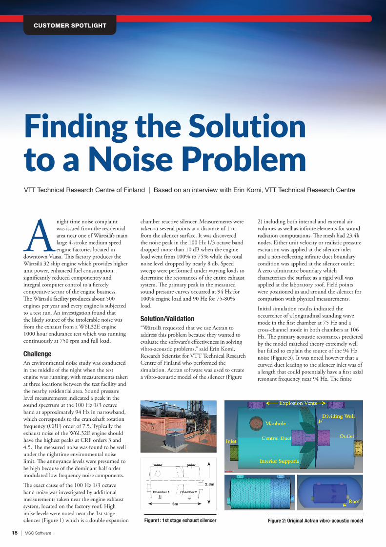
Figure1: 1st stage exhaust silencer Figure 2: Original Actran vibro-acoustic model
6m
Chamber 1 Chamber 2
2.8m
Anight time noise complaint was issued from the residential area near one of Wärtsilä’s main large 4-stroke medium speed engine factories located in
downtown Vaasa. This factory produces the Wärtsilä 32 ship engine which provides higher unit power, enhanced fuel consumption, significantly reduced componentry and integral computer control to a fiercely competitive sector of the engine business. The Wärtsilä facility produces about 500 engines per year and every engine is subjected to a test run. An investigation found that the likely source of the intolerable noise was from the exhaust from a W6L32E engine 1000 hour endurance test which was running continuously at 750 rpm and full load.
ChallengeAn environmental noise study was conducted in the middle of the night when the test engine was running, with measurements taken at three locations between the test facility and the nearby residential area. Sound pressure level measurements indicated a peak in the sound spectrum at the 100 Hz 1/3 octave band at approximately 94 Hz in narrowband, which corresponds to the crankshaft rotation frequency (CRF) order of 7.5. Typically the exhaust noise of the W6L32E engine should have the highest peaks at CRF orders 3 and 4.5. The measured noise was found to be well under the nighttime environmental noise limit. The annoyance levels were presumed to be high because of the dominant half order modulated low frequency noise components.
The exact cause of the 100 Hz 1/3 octave band noise was investigated by additional measurements taken near the engine exhaust system, located on the factory roof. High noise levels were noted near the 1st stage silencer (Figure 1) which is a double expansion
chamber reactive silencer. Measurements were taken at several points at a distance of 1 m from the silencer surface. It was discovered the noise peak in the 100 Hz 1/3 octave band dropped more than 10 dB when the engine load went from 100% to 75% while the total noise level dropped by nearly 8 db. Speed sweeps were performed under varying loads to determine the resonances of the entire exhaust system. The primary peak in the measured sound pressure curves occurred at 94 Hz for 100% engine load and 90 Hz for 75-80% load.
Solution/Validation“Wärtsilä requested that we use Actran to address this problem because they wanted to evaluate the software’s effectiveness in solving vibro-acoustic problems,” said Erin Komi, Research Scientist for VTT Technical Research Centre of Finland who performed the simulation. Actran software was used to create a vibro-acoustic model of the silencer (Figure
2) including both internal and external air volumes as well as infinite elements for sound radiation computations. The mesh had 23.4k nodes. Either unit velocity or realistic pressure excitation was applied at the silencer inlet and a non-reflecting infinite duct boundary condition was applied at the silencer outlet. A zero admittance boundary which characterizes the surface as a rigid wall was applied at the laboratory roof. Field points were positioned in and around the silencer for comparison with physical measurements.
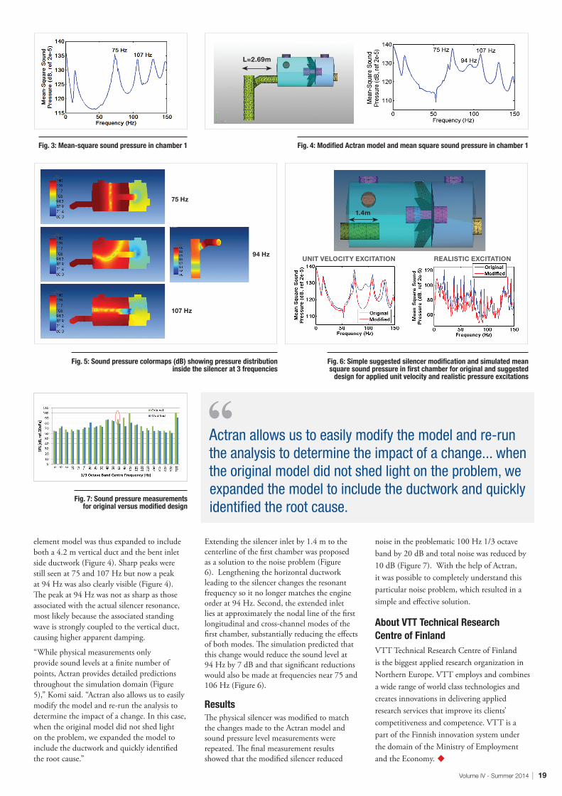
Initial simulation results indicated the occurrence of a longitudinal standing wave mode in the first chamber at 75 Hz and a cross-channel mode in both chambers at 106 Hz. The primary acoustic resonances predicted by the model matched theory extremely well but failed to explain the source of the 94 Hz noise (Figure 3). It was noted however that a curved duct leading to the silencer inlet was of a length that could potentially have a first axial resonant frequency near 94 Hz. The finite
Volume IV - Summer 2014 | 19
Fig. 3: Mean-square sound pressure in chamber 1
Fig. 5: Sound pressure colormaps (dB) showing pressure distribution inside the silencer at 3 frequencies
Fig. 6: Simple suggested silencer modification and simulated mean square sound pressure in first chamber for original and suggested
design for applied unit velocity and realistic pressure excitations
Fig. 4: Modified Actran model and mean square sound pressure in chamber 1
Fig. 7: Sound pressure measurements for original versus modified design
UNIT VELOCITY EXCITATION
L=2.69m
75 Hz
107 Hz
94 Hz
1.4m
REALISTIC EXCITATION
Actran allows us to easily modify the model and re-run the analysis to determine the impact of a change... when the original model did not shed light on the problem, we expanded the model to include the ductwork and quickly identified the root cause.
element model was thus expanded to include both a 4.2 m vertical duct and the bent inlet side ductwork (Figure 4). Sharp peaks were still seen at 75 and 107 Hz but now a peak at 94 Hz was also clearly visible (Figure 4). The peak at 94 Hz was not as sharp as those associated with the actual silencer resonance, most likely because the associated standing wave is strongly coupled to the vertical duct, causing higher apparent damping.
“While physical measurements only provide sound levels at a finite number of points, Actran provides detailed predictions throughout the simulation domain (Figure 5),” Komi said. “Actran also allows us to easily modify the model and re-run the analysis to determine the impact of a change. In this case, when the original model did not shed light on the problem, we expanded the model to include the ductwork and quickly identified the root cause.”
Extending the silencer inlet by 1.4 m to the centerline of the first chamber was proposed as a solution to the noise problem (Figure 6). Lengthening the horizontal ductwork leading to the silencer changes the resonant frequency so it no longer matches the engine order at 94 Hz. Second, the extended inlet lies at approximately the nodal line of the first longitudinal and cross-channel modes of the first chamber, substantially reducing the effects of both modes. The simulation predicted that this change would reduce the sound level at 94 Hz by 7 dB and that significant reductions would also be made at frequencies near 75 and 106 Hz (Figure 6).
ResultsThe physical silencer was modified to match the changes made to the Actran model and sound pressure level measurements were repeated. The final measurement results showed that the modified silencer reduced
noise in the problematic 100 Hz 1/3 octave band by 20 dB and total noise was reduced by 10 dB (Figure 7). With the help of Actran, it was possible to completely understand this particular noise problem, which resulted in a simple and effective solution.
About VTT Technical Research Centre of FinlandVTT Technical Research Centre of Finland is the biggest applied research organization in Northern Europe. VTT employs and combines a wide range of world class technologies and creates innovations in delivering applied research services that improve its clients’ competitiveness and competence. VTT is a part of the Finnish innovation system under the domain of the Ministry of Employment and the Economy. u
20 | MSC Software
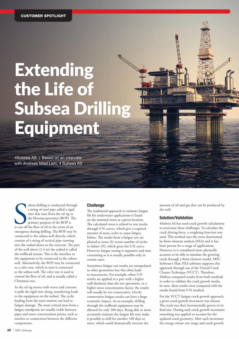
Extending the Life of Subsea Drilling Equipment
CUSTOMER SPOTLIGHT
4Subsea AS | Based on an interviewwith Andreas Istad Lem, 4 Subsea AS
Subsea drilling is conducted through a string of steel pipe called a rigid riser that runs from the oil rig to the blowout preventer (BOP). The primary purpose of the BOP is
to cut off the flow of oil in the event of an emergency during drilling. The BOP may be connected to the subsea well directly, which consists of a string of vertical pipe running into the seabed down to the reservoir. The part of the well above (2-5 m) the seabed is called the wellhead system. This is the interface to the equipment to be connected to the subsea well. Alternatively, the BOP may be connected to a valve tree, which in turn is connected to the subsea well. The valve tree is used to control the flow of oil, and is usually called a Christmas tree.
As the oil rig moves with waves and currents it pulls the rigid riser along, transferring loads to the equipment on the seabed. The cyclic loading from the wave motion can lead to fatigue damage. The most critical areas from a fatigue standpoint are usually welds between pipes and stress concentration points, such as notches or connections between the different components.
ChallengeThe traditional approach to estimate fatigue life for underwater applications is based on the nominal stress at a given location. The calculated stress is related to test results through S-N curves, which give a required amount of stress cycles to cause fatigue failure. The results from a fatigue test are plotted as stress (S) versus number of cycles to failure (N), which gives the S-N curve. However, fatigue testing is expensive and time consuming so it is usually possible only in certain cases.
Sometimes fatigue test results are extrapolated to other geometries but this often leads to inaccuracies. For example, when S-N results are applied to a part with a higher wall thickness than the test specimens, or a higher stress concentration factor, the results will usually be too conservative. Overly conservative fatigue results can have a huge economic impact. As an example, drilling through the wellhead equipment may be allowed for only 200 days. Being able to more accurately estimate the fatigue life may make it possible to drill for another 100 days or more, which could dramatically increase the
amount of oil and gas that can be produced by the well.
Solution/Validation4Subsea AS has used crack growth calculations to overcome these challenges. To calculate the crack driving force, a weighting function was used. This method uses the stress determined by finite element analysis (FEA) and it has been proven for a range of applications. However, it is considered more physically accurate to be able to simulate the growing crack through a finite element model. MSC Software’s Marc FEA software supports this approach through use of the Virtual Crack Closure Technique (VCCT). Therefore, 4Subsea compared results from both methods in order to validate the crack growth results. In turn, these results were compared with the results found from S-N method.
For the VCCT fatigue crack growth approach, a given crack growth increment was chosen. The crack was then incrementally grown to its final size. During each crack growth increment remeshing was applied to account for the updated crack geometry. After each increment the energy release rate range and crack growth
Volume IV - Summer 2014 | 21
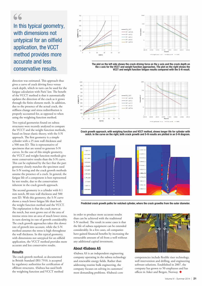
Predicted crack growth paths for notched cylinder, where the crack growths from the outer diameter.
The plot on the left side shows the crack driving force on the y axis and the crack depth on the x axis for the VCCT and weight function approaches. The plot on the right shows the
VCCT and weight function fatigue results compared with the S-N result.
Crack growth approach, with weighing function and VCCT method, shows longer life for cylinder with notch. In the curve on the right, both crack growth and S-N results are plotted in an S-N diagram.
direction was estimated. This approach thus gives a curve of crack driving force versus crack depth, which in turn can be used for the fatigue calculation with Paris’ law. The benefit of the VCCT method is that it automatically updates the direction of the crack as it grows through the finite element mesh. In addition, due to the presence of the actual crack, the stiffness change and stress redistribution is properly accounted for, as opposed to when using the weighting function method.
Two typical geometries found on subsea structures were recently analyzed to compare the VCCT and the weight function methods, based on linear elastic theory, with the S-N approach. The first geometry is a simple cylinder with a 25 mm wall thickness and a 500 mm ID. This is representative of specimens that are tested to generate S-N curves. In the case of this simple geometry, the VCCT and weight function methods give more conservative results than the S-N curve. This can be explained by the fact that the part geometry closely matches the specimen used for S-N testing and the crack growth methods assume the presence of a crack. In general, the fatigue life of a component is best represented by test results, due to the conservatism inherent in the crack growth approach.
The second geometry is a cylinder with 0.1 mm notch, 80 mm wall thickness and 500 mm ID. With this geometry, the S-N curve shows a much lower fatigue life than both the weight function method and the VCCT. The explanation is that the crack starts at the notch, but soon grows out of the area of intense stress into an area of much lower stress, in turn slowing its rate of growth considerably. The crack growth approaches takes this slower rate of growth into account, while the S-N method assumes the stress is high throughout the wall thickness. In this typical geometry, with dimensions not untypical for an oilfield application, the VCCT method provides more accurate and less conservative results.
ResultsThe crack growth method, as documented in British Standard (BS) 7910, is accepted by regulatory authorities for certification of offshore structures. 4Subsea has used both the weighting function and VCCT method
in order to produce more accurate results than can be achieved with the traditional S-N method. The result in some cases is that the life of subsea equipment can be extended considerably. In a few cases, oil companies have gained financial benefits by increasing the extractable amount of oil from a well without any additional capital investment.
About 4Subsea AS4Subsea AS is an independent engineering company operating in the subsea technology and renewable energy fields. Rather than addressing routine bulk engineering, the company focuses on solving its customers’ most demanding problems. 4Subsea’s core
competencies include flexible riser technology, well intervention and drilling, and engineering software solutions. Established in 2007, the company has grown to 50 employees and has offices in Asker and Bergen, Norway. u
In this typical geometry, with dimensions not untypical for an oilfield application, the VCCT method provides more accurate and less conservative results.
22 | MSC Software
Building the Next-Generation of Optical MirrorsCNRS-LAM, France | Based on an interview with Zalpha Challita, CNRS-LAM
CUSTOMER SPOTLIGHT
Figure 1: Overview of the principle
Astronomical telescopes and instruments enable astronomers to see into deep space and unravel the mysteries of the universe. Freeform mirror
surfaces – surfaces with a shape more complex than a symmetrical conventional mirror surface (as for example, sphere, parabola, hyperbola, etc.) - offer substantial benefits by providing additional degrees of freedom that make it possible to improve the optical performances of the instrument, reducing the overall instrument mass and size.
Freeform optical mirror surfaces must be constructed with nano-scale accuracy to produce clear images. For example, an error of only 2.2 microns on the surface of the primary mirror of the Hubble Space Telescope required one of the most complex space missions in history to correct.
Currently, freeform mirrors are usually produced by computer control optical surfacing and single-point diamond turning, which is expensive and requires long leadtimes. Researchers at the Laboratoire d’Astrophysique de Marseille (one of the public institute in astrophysics of the French National Center for Scientific Research, CNRS-LAM) are developing an innovative manufacturing process based on the plastic deformation of materials and the hydroforming process. Such a technique has the potential to reach these kind of extreme optical shapes and to substantially reduce the time and cost required for manufacturing to demanding tolerance levels. The hydroforming technique deforms the material to its final form thanks to the contact with a specific mold shape in a single step, by applying a fluid at high pressure directly on the optical surface. This method also has the potential to produce a higher quality surface because it eliminates the need for a mechanical tool to contact the mirror surface.
ChallengeThe hydroforming process is difficult to design and optimize because the mirror undergoes plastic deformation to provide a freeform optical surface. While the elastic behavior of materials is well known and frequently modeled in optical manufacturing, the analysis of materials under stress in the plastic domain is much more difficult because it involves both material and geometric nonlinearities. One particular importance is the quantifying of the springback effect, in order to control the final shape of the mirror.
In a typical case, the objective is to produce an optical diameter from 100 mm to 300 mm with residual form errors of few micrometers and roughness less than few nanometers rms. Achieving these goals requires analyzing the global structural behavior of the substrate while taking into account work-hardening, anisotropy, contact conditions, boundary conditions and load cases applied during the hydroforming process.
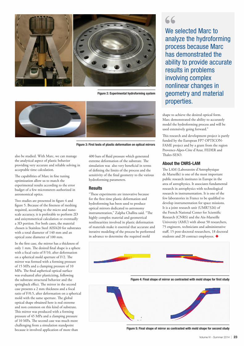
Solution/ValidationWe selected Marc to analyze the hydroforming process because Marc has demonstrated the ability to provide accurate results in problems involving complex nonlinear changes in geometry and materials properties,” said Zalpha Challita, in post-doctoral position at CNRS-LAM. An overview of the hydroforming process is shown in Figure 1. As shown the substrate is divided into three zones. The edge zone maintains the mirror in position and centered within the mold during the hydroforming process. The flange zone is in line with the mold flange to partition the stresses inside the substrate and improve the conservation of plastic deformation after the process. The optical zone is deformed to the freeform shape required by the optical design. A homogenous pressure is applied on the substrate optical zone while a clamping
pressure is applied on the edge zone. Materials used include stainless steel, aluminum, and titanium because they possess a large plastic domain, good elastic behavior and the ability to be optically polished.
FEA was performed with Marc to quantify the residual errors after the hydroforming process and to optimize the system. The first step consisted in a coarse model of the system and then refined on the more sensitive parameters which were deduced from real hydroforming tests. The optimized parameters are, for example, hydroforming parameters such as clamping and forming pressures and optical parameters concerning the overall geometry of the initial mirror and of the mold shape. Contact analysis between the mold and the back of the mirror is also performed. The final shape of the deformed substrate after the conclusion of the hydroforming process is then extracted from Marc and treated optically.
Marc can take into account different sets of macroscopic and microscopic material parameters and effects as for example the evolution of the strain and the Young Modulus during the work-hardening and the micro-structural composition of the material. FEA is used to study the springback effect, the accuracy of which depends on the material data and the meshing fineness, according to acceptable time calculation. The main zones of roughness evolution on the mirror surface can
Volume IV - Summer 2014 | 23
Figure 4: Final shape of mirror as contrasted with mold shape for first study
Figure 5: Final shape of mirror as contrasted with mold shape for second study
Figure 2: Experimental hydroforming system
Figure 3: First tests of plastic deformation on optical mirrors
also be studied. With Marc, we can manage the analytical aspect of plastic behavior providing very accurate and reliable solving in acceptable time calculation.
The capabilities of Marc in fine tuning optimization allow us to match the experimental results according to the error budget of a few micrometers authorized in astronomical optics.
Two studies are presented in figure 4 and figure 5. Because of the fineness of meshing required, according to the micro and nano-scale accuracy, it is preferable to perform 2D and axisymmetrical calculation or eventually a 3D portion. For both cases, the material chosen is Stainless Steel AISI420 for substrates with a total diameter of 140 mm and an optical zone diameter of 100 mm.
In the first case, the mirror has a thickness of only 1 mm. The desired final shape is a sphere with a focal ratio of F/10, after deformation on a spherical mold aperture of F/2. The mirror was formed with a forming pressure of 15 MPa and a clamping pressure of 10 MPa. The final aspherical optical surface was evaluated after plasticizing, following the substrate structural behavior and the springback effect. The mirror in the second case presents a 2 mm thickness and a focal ratio of F/0.5, after deformation on a spherical mold with the same aperture. The global optical shape obtained here is real extreme and non common on this kind of substrate. This mirror was produced with a forming pressure of 45 MPa and a clamping pressure of 10 MPa. The second case was much more challenging from a simulation standpoint because it involved application of more than
400 bars of fluid pressure which generated extreme deformation of the substrate. The simulation was also very beneficial in terms of defining the limits of the process and the sensitivity of the final geometry to the various hydroforming parameters.
Results“These experiments are innovative because for the first time plastic deformation and hydroforming has been used to produce optical mirrors dedicated to astronomy instrumentation,” Zalpha Challita said. “The highly complex material and geometrical nonlinearities involved in plastic deformation of materials make it essential that accurate and iterative modeling of the process be performed in advance to determine the required mold
shape to achieve the desired optical form. Marc demonstrated the ability to accurately model the hydroforming process and will be used extensively going forward.”
This research and development project is partly funded by the European FP7 OPTICON-FAME project and by a grant from the region Provence-Alpes-Côte d’Azur, FEDER and Thales-SESO.
About the CNRS-LAMThe LAM (Laboratoire d’Astrophysique de Marseille) is one of the most important public research institutes in Europe in the area of astrophysics. It associates fundamental research in astrophysics with technological research in instrumentation. It is one of the few laboratories in France to be qualified to develop instrumentation for space missions. It is a joint research unit (UMR7326) of the French National Center for Scientific Research (CNRS) and the Aix-Marseille University (AMU) with about 50 researchers, 75 engineers, technicians and administrative staff, 15 post-doctoral researchers, 18 doctoral students and 20 contract employees. u
We selected Marc to analyze the hydroforming process because Marc has demonstrated the ability to provide accurate results in problems involving complex nonlinear changes in geometry and material properties.
24 | MSC Software
TWO WAYS TO DEACTIVATE A JOINT DURING AN ADAMS SIMULATION
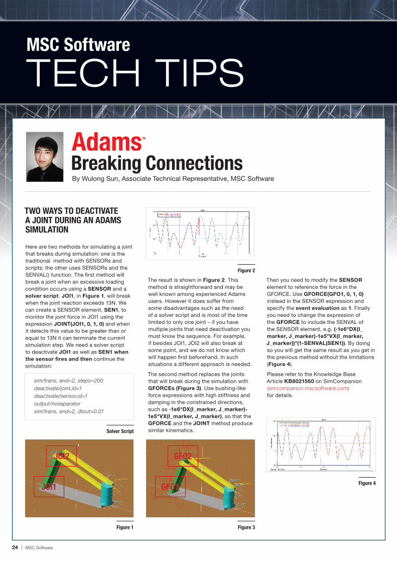
Here are two methods for simulating a joint that breaks during simulation: one is the traditional method with SENSORs and scripts; the other uses SENSORs and the SENVAL() function. The first method will break a joint when an excessive loading condition occurs using a SENSOR and a solver script. JOI1, in Figure 1, will break when the joint reaction exceeds 13N. We can create a SENSOR element, SEN1, to monitor the joint force in JOI1 using the expression JOINT(JOI1, 0, 1, 0) and when it detects this value to be greater than or equal to 13N it can terminate the current simulation step. We need a solver script to deactivate JOI1 as well as SEN1 when the sensor fires and then continue the simulation:
Then you need to modify the SENSOR element to reference the force in the GFORCE. Use GFORCE(GFO1, 0, 1, 0) instead in the SENSOR expression and specify the event evaluation as 1. Finally you need to change the expression of the GFORCE to include the SENVAL of the SENSOR element, e.g. (-1e6*DX(I_marker, J_marker)-1e5*VX(I_marker, J_marker))*(1-SENVAL(SEN1)). By doing so you will get the same result as you get in the previous method without the limitations (Figure 4).
Please refer to the Knowledge Base Article KB8021560 on SimCompanion (simcompanion.mscsoftware.com) for details.
The result is shown in Figure 2. This method is straightforward and may be well known among experienced Adams users. However it does suffer from some disadvantages such as the need of a solver script and is most of the time limited to only one joint – if you have multiple joints that need deactivation you must know the sequence. For example, if besides JOI1, JOI2 will also break at some point, and we do not know which will happen first beforehand. In such situations a different approach is needed.
The second method replaces the joints that will break during the simulation with GFORCEs (Figure 3). Use bushing-like force expressions with high stiffness and damping in the constrained directions, such as -1e6*DX(I_marker, J_marker)-1e5*VX(I_marker, J_marker), so that the GFORCE and the JOINT method produce similar kinematics.
Mentat starts with certain default fonts, colors and window size. It is quite easy to change these settings so that it always opens up with your preferences loaded. Multiple options and layers of customiza-tion are available in this regard.
Using Mentat Menus
To change the Graphics Font, i.e. the text you see in the graphics window, go to View
-> Graphics Font and choose the desired font name and size. To change the Menu Font, you would go to Tools -> Set Menu Font and choose the desired font. You can also open up any pop-up windows that you would like access to when Mentat is started, and then save these settings with Tools -> Popup menu settings -> Save popup menu settings. You can also adjust the window size (full screen, half-screen size etc.). Once you are satisfied with these settings, you can save them with Tools -> Windows Settings -> Save Window Set-tings. The next time you start Mentat, these new settings are used. If you would like to remove all the changes you have made, you can use Restore Window settings.
Using Command Prompt
Although Mentat is generally started without any options, there are several command options available. Assuming Mentat installation directory is in your path, if you type ‘mentat –help’ in a command window, you will get a host of options you can use, including options to change fonts, window size, menu visibility, gradient color view for graphics window and more. If you have never looked at this list, this would be something to be familiar with.
One of the options available, “- pr filename”, can be quite useful if you want to custom-ize Mentat’s appearance further. This option allows you to read in any additional set-up commands you would like to run
when you start Mentat. The steps are as follows.
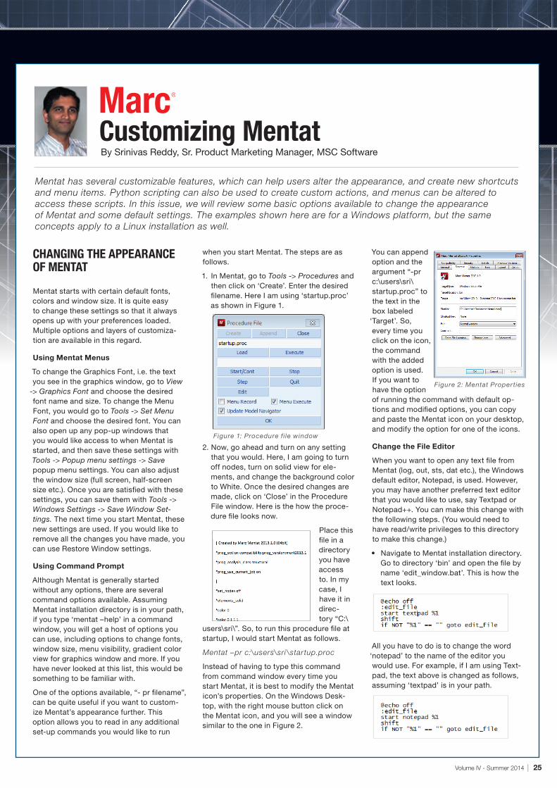
1. In Mentat, go to Tools -> Procedures and then click on ‘Create’. Enter the desired filename. Here I am using ‘startup.proc’ as shown in Figure 1.
2. Now, go ahead and turn on any setting that you would. Here, I am going to turn off nodes, turn on solid view for ele-ments, and change the background color to White. Once the desired changes are made, click on ‘Close’ in the Procedure File window. Here is the how the proce-dure file looks now.
Place this file in a directory you have access to. In my case, I have it in direc-tory “C:\
users\sri\”. So, to run this procedure file at startup, I would start Mentat as follows.
Mentat –pr c:\users\sri \startup.proc
Instead of having to type this command from command window every time you start Mentat, it is best to modify the Mentat icon’s properties. On the Windows Desk-top, with the right mouse button click on the Mentat icon, and you will see a window similar to the one in Figure 2.
You can append option and the argument “-pr c:\users\sri\startup.proc” to the text in the box labeled
‘Target’. So, every time you click on the icon, the command with the added option is used. If you want to have the option of running the command with default op-tions and modified options, you can copy and paste the Mentat icon on your desktop, and modify the option for one of the icons.
Change the File Editor
When you want to open any text file from Mentat (log, out, sts, dat etc.), the Windows default editor, Notepad, is used. However, you may have another preferred text editor that you would like to use, say Textpad or Notepad++. You can make this change with the following steps. (You would need to have read/write privileges to this directory to make this change.)
• Navigate to Mentat installation directory. Go to directory ‘bin’ and open the file by name ‘edit_window.bat’. This is how the text looks.
All you have to do is to change the word ‘notepad’ to the name of the editor you would use. For example, if I am using Text-pad, the text above is changed as follows, assuming ‘textpad’ is in your path.
Mentat has several customizable features, which can help users alter the appearance, and create new shortcuts and menu items. Python scripting can also be used to create custom actions, and menus can be altered to access these scripts. In this issue, we will review some basic options available to change the appearance of Mentat and some default settings. The examples shown here are for a Windows platform, but the same concepts apply to a Linux installation as well.
Figure 1: Procedure file window
Figure 2: Mentat Properties
26 | MSC Software
Useful Group ToolsBy Christian Aparicio, Product Marketing Manager, MSC Software
HOW TO QUICKLY FIND ELEMENTS WITH NO PROPERTY ASSIGNMENTS:
There may be that point in your finite element modeling when Patran or MSC Nastran indicates some of your finite elements have no properties assigned to them.
Patran has a useful tool that will search, find, and collect in one group every element that has not been assigned properties.
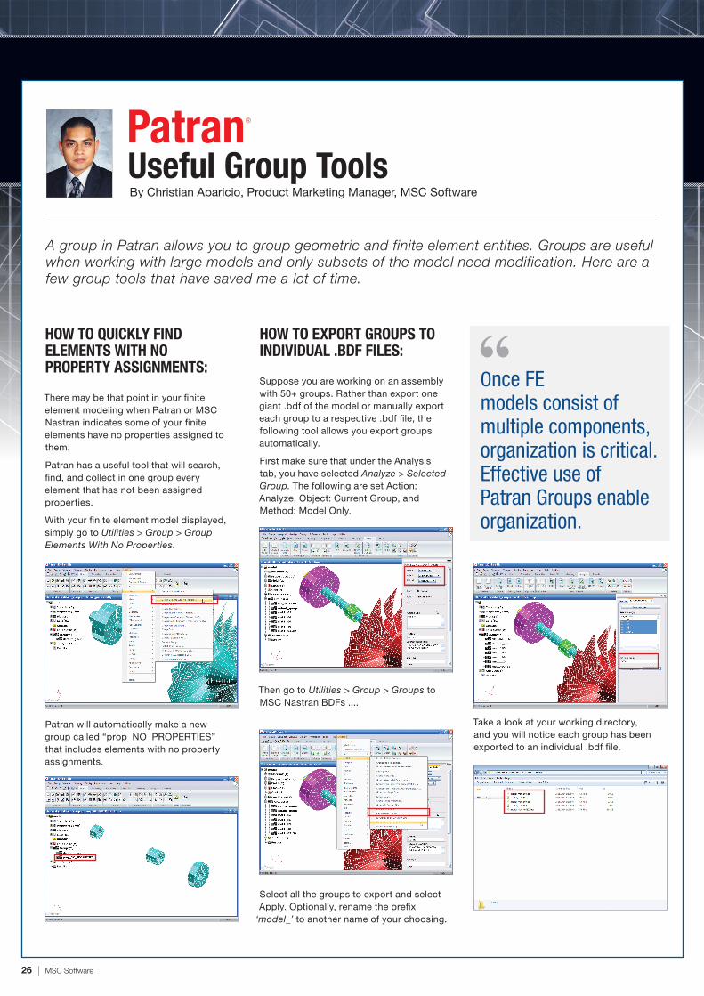
With your finite element model displayed, simply go to Utilities > Group > Group Elements With No Properties.
Patran will automatically make a new group called “prop_NO_PROPERTIES” that includes elements with no property assignments.
HOW TO EXPORT GROUPS TO INDIVIDUAL .BDF FILES:
Suppose you are working on an assembly with 50+ groups. Rather than export one giant .bdf of the model or manually export each group to a respective .bdf file, the following tool allows you export groups automatically.
First make sure that under the Analysis tab, you have selected Analyze > Selected Group. The following are set Action: Analyze, Object: Current Group, and Method: Model Only.
Then go to Utilities > Group > Groups to MSC Nastran BDFs ....
Select all the groups to export and select Apply. Optionally, rename the prefix
‘model_’ to another name of your choosing.
Take a look at your working directory, and you will notice each group has been exported to an individual .bdf file.
A group in Patran allows you to group geometric and finite element entities. Groups are useful when working with large models and only subsets of the model need modification. Here are a few group tools that have saved me a lot of time.
Once FE models consist of multiple components, organization is critical. Effective use of Patran Groups enable organization.
Volume IV - Spring 2014 | 50
MSC Software
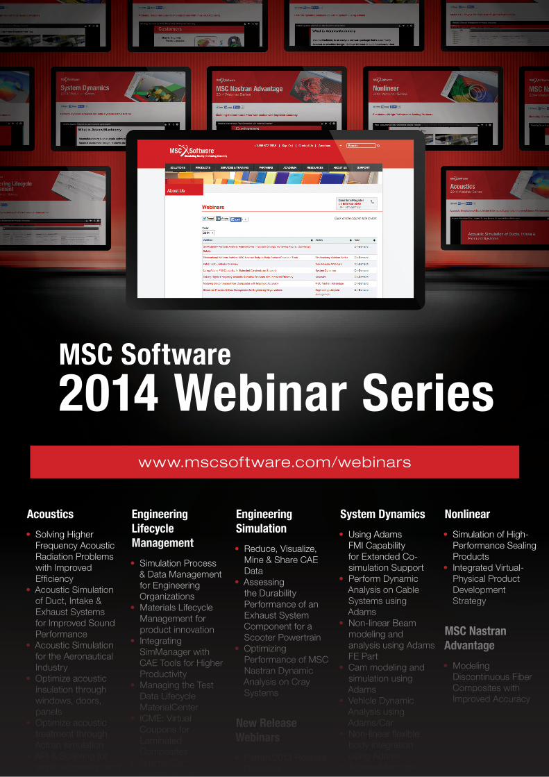
2014 Webinar Serieswww.mscsoftware.com/webinars
Acoustics
• Solving Higher Frequency Acoustic Radiation Problems with Improved Efficiency
• Acoustic Simulation of Duct, Intake & Exhaust Systems for Improved Sound Performance
• Acoustic Simulation for the Aeronautical Industry
• Optimize acoustic insulation through windows, doors, panels
• Optimize acoustic treatment through Actran simulation
• API & Scripting for work automation and design optimization for acoustic analysis
Engineering Lifecycle Management
• Simulation Process & Data Management for Engineering Organizations
• Materials Lifecycle Management for product innovation
• Integrating SimManager with CAE Tools for Higher Productivity
• Managing the Test Data Lifecycle MaterialCenter
• ICME: Virtual Coupons for Laminated Composites
• Adams/Car integration with SimManager
Engineering Simulation
• Reduce, Visualize, Mine & Share CAE Data
• Assessing the Durability Performance of an Exhaust System Component for a Scooter Powertrain
• Optimizing Performance of MSC Nastran Dynamic Analysis on Cray Systems
New Release Webinars
• Patran 2013 Release Overview
System Dynamics
• Using Adams FMI Capability for Extended Co-simulation Support
• Perform Dynamic Analysis on Cable Systems using Adams
• Non-linear Beam modeling and analysis using Adams FE Part
• Cam modeling and simulation using Adams
• Vehicle Dynamic Analysis using Adams/Car
• Non-linear flexible body integration using Adams
• Adams-Marc co-simulation for higher accuracy simulation
Nonlinear
• Simulation of High-Performance Sealing Products
• Integrated Virtual-Physical Product Development Strategy
MSC Nastran Advantage
• Modeling Discontinuous Fiber Composites with Improved Accuracy
12_Ads.indd 50 5/2/14 1:36 PM
28 | MSC Software
SPECIAL SPOTLIGHT
2014 CONTEST WINNERS
Top 3 University Winners
About the Contest
Top 3 Industrial Winners
Control Integrated Dynamic analysis of a Cable-Driven 6-DOF Loading Simulator
MSC Products Illustrated: Adams
Individuals from industry and academia were invited to participate in the 2014 “Simulating Reality” contest by submitting a video or image demonstrating how they used MSC Software technology to develop interesting products and future design innovations.
We are proud to announce the Winners:
Evaluating new and existing orthopedic implants using FEA method
MSC Products Illustrated: Marc
Modeling and simulation impact on development and testing phases of an assistive robotic device.
MSC Products Illustrated: Adams
Welding simulation of nozzles for the WWER nuclear pressure vessel.
MSC Products Illustrated: Marc
Virtual test of NASA’s Morpheus vehicle to examine and analyze flight trajectory as well as observe vehicle motion from any angle and at any playback speed.
MSC Products Illustrated: Adams
Performing two wheelers bump rig simulation and two poster rig simulation on Motorcycle.
MSC Products Illustrated: Adams
Yousef B. Bedoustani, Ecole de technologie superieure (ETS), Canada
Zoltan Bezi, Bay Zoltán Nonprofit Ltd. for Applied Research, Hungary
Michael Burlone, NASA Johnson Space Center, USA
Mihir Bhambri and R. Pradeepak, Mahindra Two Wheelers, India
The images or videos, and related descriptions submitted by participants were to meet one or more of the following criteria in connection with use of MSC technology:
• Showcase innovative industry applications• Demonstrate resulting business benefits• Showcase great impact on society or industry• Demonstrate leading edge product design
Volume IV - Summer 2014 | 29
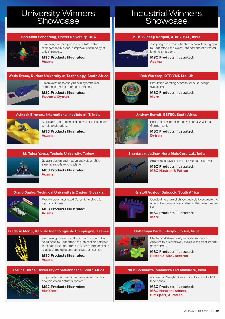
Evaluating surface geometry of total ankle replacement in order to improve functionality of ankle implants.
MSC Products Illustrated: Adams
Benjamin Senderling, Drexel University, USA
Crashworthiness analysis of a hypothetical composite aircraft impacting into soil.
MSC Products Illustrated: Patran & Dytran
Wade Evans, Durban University of Technology, South Africa
Modular robot design and analysis for the uneven terrain exploration.
MSC Products Illustrated: Adams
Avinash Siravuru, International Institute of IT, India
System design and motion analysis on Skid-steering mobile robotic platform.
MSC Products Illustrated: Adams
M. Tolga Yavuz, Technic University, Turkey
Flexible body integrated Dynamic analysis for Hydraulic Crane.
MSC Products Illustrated: Adams
Brano Danko, Technical University in Zvolen, Slovakia
Performing fusion of a 3D-reconstruction of the hand bone to understand the interaction between the anatomical structures in order to present hand related pathologies and anticipate outcomes.
MSC Products Illustrated: Adams
Frédéric Marin, Univ. de technologie de Compiègne, France
Large deflection non-linear analysis and motion analysis on an Actuator system.
MSC Products Illustrated: SimXpert
Theuns Botha, University of Stellenbosch, South Africa
Analyzing the arrestor hook of a naval landing gear to understand the overall phenomena of arrested landing on a deck.
MSC Products Illustrated: Adams
K. B. Sudeep Karipali, ARDC, HAL, India
Simulation of rating process for bush design evaluation.
MSC Products Illustrated: Marc
Rob Wardrop, DTR VMS Ltd. UK
Performing mine blast analysis on a WWII era German tank.
MSC Products Illustrated: Dytran
Andrew Berndt, ESTEQ, South Africa
Structural analysis of front fork on a motorcycle.
MSC Products Illustrated: MSC Nastran & Patran
Shantaram Jadhav, Hero MotoCorp Ltd., India
Conducting thermal stress analysis to estimate the effect of excessive ramp rates on the boiler header life.
MSC Products Illustrated: Marc
Kristoff Vosloo, Babcock. South Africa
Mechanical stress analysis of osteoporosis vertebra to quantitatively evaluate the fracture risk of vertebrae.
MSC Products Illustrated: Patran & MSC Nastran
Dattatraya Parle, Infosys Limited, India
Automating Weight Optimization Process for NVH load cases.
EC Engineering Sp. z o.o. of Poland, is one of the fastest growing design and development offices in Europe. The company achieved the status of Research and Development Centre in 2009, and employs over 250 engineers.
Our SpecialtyWe participate in the design and development of high-speed trains in Germany, Italy, China, as well as other vehicles in countries like Austria, Belgium, France, Netherlands, Czech Republic, Romania and Japan. Every year, the company expands in international markets; and now services the Asian region.
Our HistoryThanks to a long-term cooperation with a leading company in the production of rail vehicles, Bombardier Transportation, we participate in preparatory design works of ZEFIRO high-speed trains. Since 2004, we have also been involved in many aviation-related projects including Airbus A380 and Airbus A350. Since 2010, we have also been engaged in several manufacturing projects. Our first product is the 160EC pantograph, designed by the EC Engineering specialist. We are also a major manufacturer of tooling and instrumentation.
Company Departments Include:• Railway• Aviation• Automotive• Software
• Production
Software Solutions
EC Engineering Sp. z o.o. is an authorized representative of CAE (Computer Aided Engineering) simulation software vendors in Poland, Czech Republic and Slovakia.
MSC Software (only in Poland), Simufact, DYNAmore, Vi-Grade, Simulent
We offer: CAE software, Support, Training
By EC Engineering, an MSC Software Business Partner
SPECIAL SPOTLIGHT
Volume IV - Summer 2014 | 31
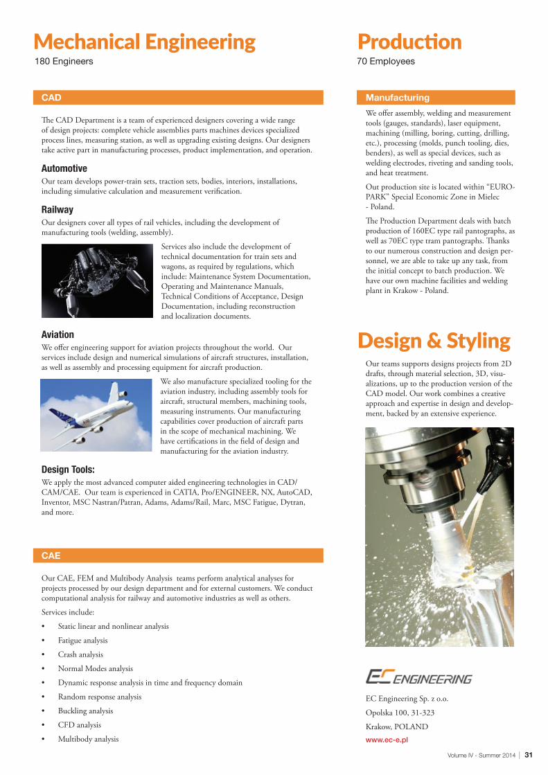
Manufacturing
We offer assembly, welding and measurement tools (gauges, standards), laser equipment, machining (milling, boring, cutting, drilling, etc.), processing (molds, punch tooling, dies, benders), as well as special devices, such as welding electrodes, riveting and sanding tools, and heat treatment.
Out production site is located within “EURO-PARK” Special Economic Zone in Mielec - Poland.
The Production Department deals with batch production of 160EC type rail pantographs, as well as 70EC type tram pantographs. Thanks to our numerous construction and design per-sonnel, we are able to take up any task, from the initial concept to batch production. We have our own machine facilities and welding plant in Krakow - Poland.
Our teams supports designs projects from 2D drafts, through material selection, 3D, visu-alizations, up to the production version of the CAD model. Our work combines a creative approach and expertise in design and develop-ment, backed by an extensive experience.
EC Engineering Sp. z o.o.
Opolska 100, 31-323
Krakow, POLANDwww.ec-e.pl
CAD The CAD Department is a team of experienced designers covering a wide range of design projects: complete vehicle assemblies parts machines devices specialized process lines, measuring station, as well as upgrading existing designs. Our designers take active part in manufacturing processes, product implementation, and operation.
Automotive Our team develops power-train sets, traction sets, bodies, interiors, installations, including simulative calculation and measurement verification.
Railway Our designers cover all types of rail vehicles, including the development of manufacturing tools (welding, assembly).
Services also include the development of technical documentation for train sets and wagons, as required by regulations, which include: Maintenance System Documentation, Operating and Maintenance Manuals, Technical Conditions of Acceptance, Design Documentation, including reconstruction and localization documents.
Aviation We offer engineering support for aviation projects throughout the world. Our services include design and numerical simulations of aircraft structures, installation, as well as assembly and processing equipment for aircraft production.
We also manufacture specialized tooling for the aviation industry, including assembly tools for aircraft, structural members, machining tools, measuring instruments. Our manufacturing capabilities cover production of aircraft parts in the scope of mechanical machining. We have certifications in the field of design and manufacturing for the aviation industry.
Design Tools: We apply the most advanced computer aided engineering technologies in CAD/CAM/CAE. Our team is experienced in CATIA, Pro/ENGINEER, NX, AutoCAD, Inventor, MSC Nastran/Patran, Adams, Adams/Rail, Marc, MSC Fatigue, Dytran, and more.
CAE Our CAE, FEM and Multibody Analysis teams perform analytical analyses for projects processed by our design department and for external customers. We conduct computational analysis for railway and automotive industries as well as others.
Services include:
• Static linear and nonlinear analysis
• Fatigue analysis
• Crash analysis
• Normal Modes analysis
• Dynamic response analysis in time and frequency domain
• Random response analysis
• Buckling analysis
• CFD analysis
• Multibody analysis
Mechanical Engineering Production
Design & Styling
180 Engineers 70 Employees
SIMULATION IN ACTION
32 | MSC Software
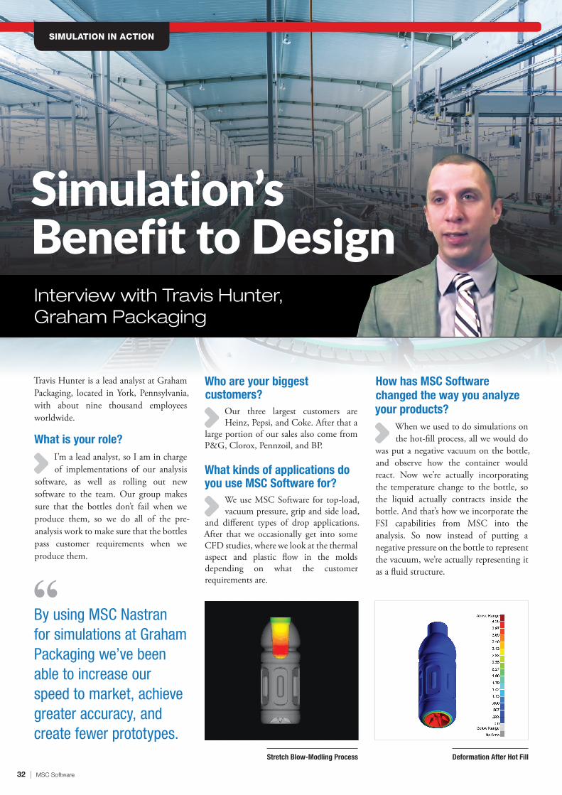
Interview with Travis Hunter, Graham Packaging
Simulation’s Benefit to Design
Stretch Blow-Modling Process Deformation After Hot Fill
By using MSC Nastran for simulations at Graham Packaging we’ve been able to increase our speed to market, achieve greater accuracy, and create fewer prototypes.
Travis Hunter is a lead analyst at Graham Packaging, located in York, Pennsylvania, with about nine thousand employees worldwide.
What is your role?I’m a lead analyst, so I am in charge of implementations of our analysis
software, as well as rolling out new software to the team. Our group makes sure that the bottles don’t fail when we produce them, so we do all of the pre-analysis work to make sure that the bottles pass customer requirements when we produce them.
Who are your biggest customers?
Our three largest customers are Heinz, Pepsi, and Coke. After that a
large portion of our sales also come from P&G, Clorox, Pennzoil, and BP.
What kinds of applications do you use MSC Software for?
We use MSC Software for top-load, vacuum pressure, grip and side load,
and different types of drop applications. After that we occasionally get into some CFD studies, where we look at the thermal aspect and plastic flow in the molds depending on what the customer requirements are.
How has MSC Software changed the way you analyze your products?
When we used to do simulations on the hot-fill process, all we would do
was put a negative vacuum on the bottle, and observe how the container would react. Now we’re actually incorporating the temperature change to the bottle, so the liquid actually contracts inside the bottle. And that’s how we incorporate the FSI capabilities from MSC into the analysis. So now instead of putting a negative pressure on the bottle to represent the vacuum, we’re actually representing it as a fluid structure.
Volume IV - Summer 2014 | 33
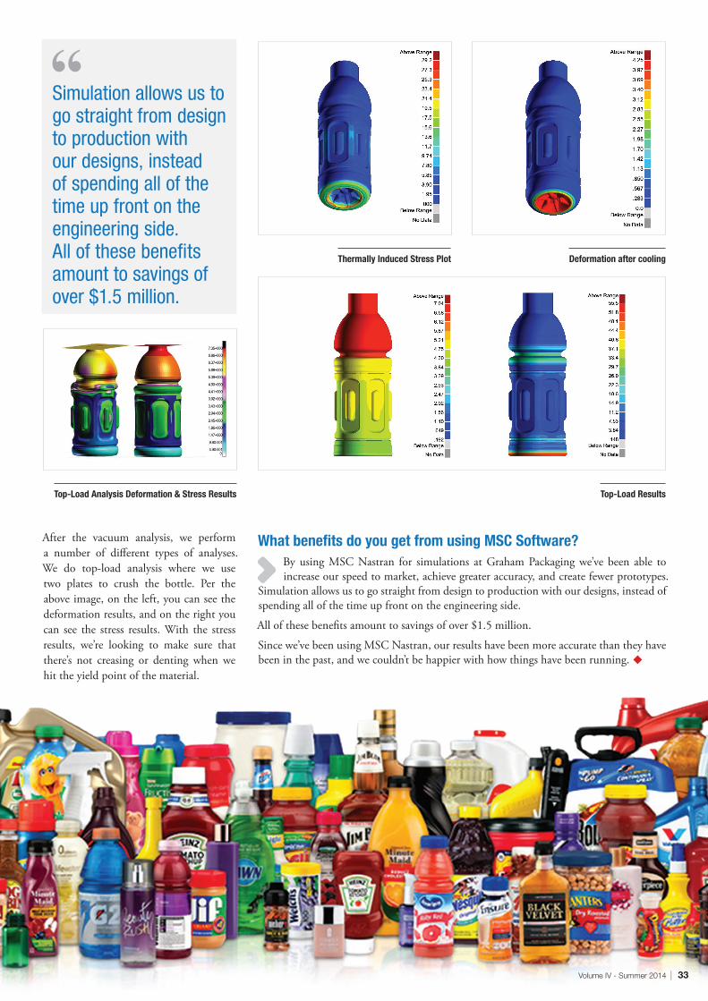
Thermally Induced Stress Plot Deformation after cooling
Simulation allows us to go straight from design to production with our designs, instead of spending all of the time up front on the engineering side. All of these benefits amount to savings of over $1.5 million.
After the vacuum analysis, we perform a number of different types of analyses. We do top-load analysis where we use two plates to crush the bottle. Per the above image, on the left, you can see the deformation results, and on the right you can see the stress results. With the stress results, we’re looking to make sure that there’s not creasing or denting when we hit the yield point of the material.
What benefits do you get from using MSC Software?By using MSC Nastran for simulations at Graham Packaging we’ve been able to increase our speed to market, achieve greater accuracy, and create fewer prototypes.
Simulation allows us to go straight from design to production with our designs, instead of spending all of the time up front on the engineering side.
All of these benefits amount to savings of over $1.5 million.
Since we’ve been using MSC Nastran, our results have been more accurate than they have been in the past, and we couldn’t be happier with how things have been running. u
34 | MSC Software
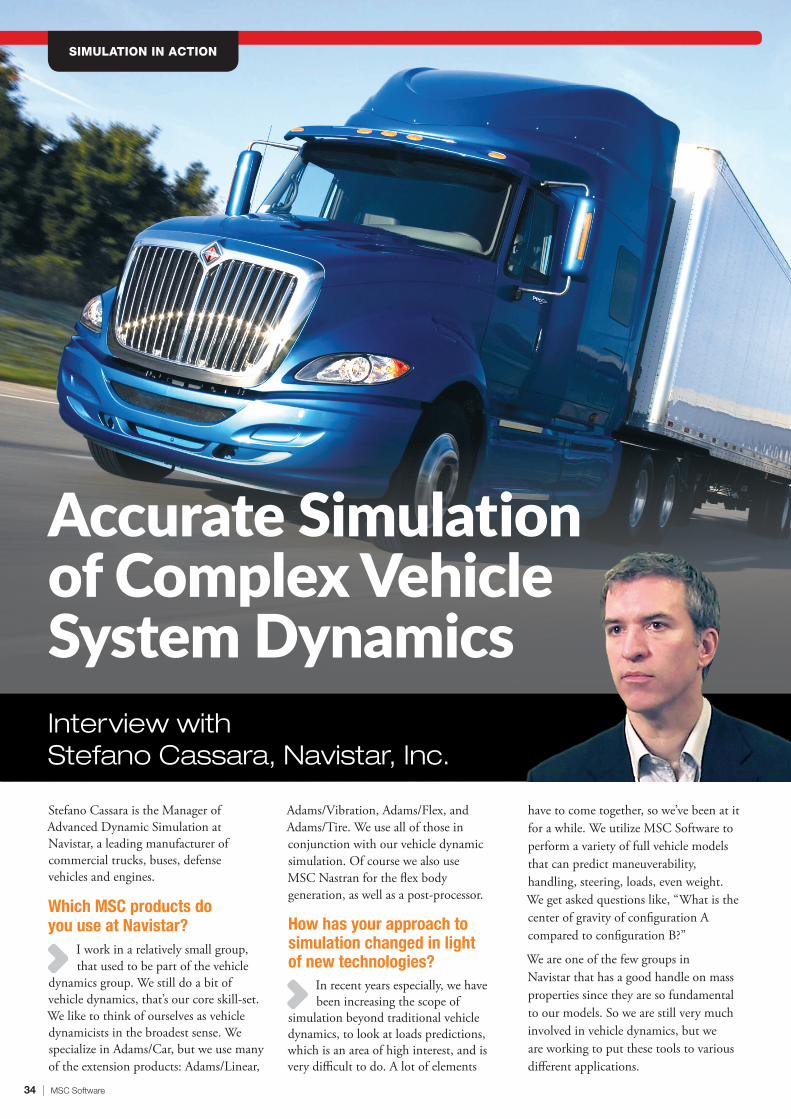
Stefano Cassara is the Manager of Advanced Dynamic Simulation at Navistar, a leading manufacturer of commercial trucks, buses, defense vehicles and engines.
Which MSC products do you use at Navistar?
I work in a relatively small group, that used to be part of the vehicle
dynamics group. We still do a bit of vehicle dynamics, that’s our core skill-set. We like to think of ourselves as vehicle dynamicists in the broadest sense. We specialize in Adams/Car, but we use many of the extension products: Adams/Linear,
Adams/Vibration, Adams/Flex, and Adams/Tire. We use all of those in conjunction with our vehicle dynamic simulation. Of course we also use MSC Nastran for the flex body generation, as well as a post-processor.
How has your approach to simulation changed in light of new technologies?
In recent years especially, we have been increasing the scope of
simulation beyond traditional vehicle dynamics, to look at loads predictions, which is an area of high interest, and is very difficult to do. A lot of elements
have to come together, so we’ve been at it for a while. We utilize MSC Software to perform a variety of full vehicle models that can predict maneuverability, handling, steering, loads, even weight. We get asked questions like, “What is the center of gravity of configuration A compared to configuration B?”
We are one of the few groups in Navistar that has a good handle on mass properties since they are so fundamental to our models. So we are still very much involved in vehicle dynamics, but we are working to put these tools to various different applications.
SIMULATION IN ACTION
Accurate Simulation of Complex Vehicle System DynamicsInterview with Stefano Cassara, Navistar, Inc.
Volume IV - Summer 2014 | 35
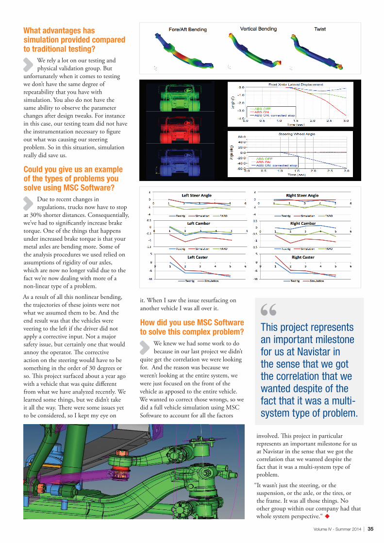
What advantages has simulation provided compared to traditional testing?
We rely a lot on our testing and physical validation group. But
unfortunately when it comes to testing we don’t have the same degree of repeatability that you have with simulation. You also do not have the same ability to observe the parameter changes after design tweaks. For instance in this case, our testing team did not have the instrumentation necessary to figure out what was causing our steering problem. So in this situation, simulation really did save us.
Could you give us an example of the types of problems you solve using MSC Software?
Due to recent changes in regulations, trucks now have to stop
at 30% shorter distances. Consequentially, we’ve had to significantly increase brake torque. One of the things that happens under increased brake torque is that your metal axles are bending more. Some of the analysis procedures we used relied on assumptions of rigidity of our axles, which are now no longer valid due to the fact we’re now dealing with more of a non-linear type of a problem.
As a result of all this nonlinear bending, the trajectories of these joints were not what we assumed them to be. And the end result was that the vehicles were veering to the left if the driver did not apply a corrective input. Not a major safety issue, but certainly one that would annoy the operator. The corrective action on the steering would have to be something in the order of 30 degrees or so. This project surfaced about a year ago with a vehicle that was quite different from what we have analyzed recently. We learned some things, but we didn’t take it all the way. There were some issues yet to be considered, so I kept my eye on
it. When I saw the issue resurfacing on another vehicle I was all over it.
How did you use MSC Software to solve this complex problem?
We knew we had some work to do because in our last project we didn’t
quite get the correlation we were looking for. And the reason was because we weren’t looking at the entire system, we were just focused on the front of the vehicle as apposed to the entire vehicle. We wanted to correct those wrongs, so we did a full vehicle simulation using MSC Software to account for all the factors
involved. This project in particular represents an important milestone for us at Navistar in the sense that we got the correlation that we wanted despite the fact that it was a multi-system type of problem.
“It wasn’t just the steering, or the suspension, or the axle, or the tires, or the frame. It was all those things. No other group within our company had that whole system perspective.“ u
This project represents an important milestone for us at Navistar in the sense that we got the correlation that we wanted despite of the fact that it was a multi-system type of problem.
36 | MSC Software
By Dr. Stefan Beermann, CEO of KISSsoft
KISSsoft is an MSC Technology Partner, whose roller bearing technology is incorporated into Adams/Machinery, allowing full non-linear stiffness of roller bearings to be modeled and used within the Adams/Machinery environment.
Sharing Knowledge to Expand Reliability
PARTNER SHOWCASE
When it comes to calculating lifetime and stiffness of bearings, engineers have several
methods to choose from. The simplest method is defined in the standard DIN/ISO 281 as the L10 calculation; the number 10 referring to the percentage of bearings that have failed before the calculated lifetime. While it is simple to use, since many effects are not considered, this method only provides a very rough idea of the actual life of the bearing.
An improved method has been available for a few years. It is defined in the ISO/TS 16281 standards as the reference method, designating it as the method an engineer would choose if they wish to compare calculations (and quotations) from different manufacturers. Since the reference method models the Hertzian contact of rolling elements and races, it is beyond manual calculation. When a computer program performs the calculations according to this standard, the resulting model closely resembles the actual physics of the bearing. This is because all effects that will influence the contact and clearance are automatically taken into account. Of the many factors
taken into account are various types of translations and rotations of the rings, deformations of the rings i.e. interference fits, thermal effects, profiles of rolls and so on. An additional benefit the reference method delivers is the stiffness of the bearing while taking the same factors into account. Therefore, the stiffness of the bearing can be calculated in accordance to its unique, factual situation.
KISSsoft and KISSsysKISSsoft is a software package, developed as a modular calculation system for the design, optimization and analysis of machine elements. Calculations ranging from a single machine element to the automatic sizing of complete gearboxes can be performed. KISSsys, available as an add-on, enables the modeling of complete gear units and drivetrains, empowering the user to analyze a machine’s gears, shafts and bearings at the same time. KISSsys can be used to calculate any type of driven kinematic. Custom calculations and designs can be implemented with its integrated programming language. In addition, the
“Gearbox variant generator” automatically generates numerous gearbox variants, all with the same required reduction and
performance, but with different numbers of stages and reduction distributions over those stages. The strength can be verified according to ISO or other standards,
By partnering with KISSsoft, we benefit from their high level of knowledge and the use of their existing and proven calculation codes. So far, the collaboration has led to an easy-to-use chain for modeling via dynamic simulation in Adams, up to creation of non-numerical yet essential gear train results.
Volume IV - Summer 2014 | 37
Figure 1: Load Distribution
Figure 2: Planetary Stage
and space requirements fulfilled. The software can be used in many different sectors including the automotive and wind power industries, as well as the manufacture of agricultural machinery, power tools, industrial gearboxes and much more.
Since 2008, KISSsoft includes the new ISO/TS 16281 standard. By default, the roller bearings’ rollers are logarithmic as defined in the standard. However, custom-defined profiles can be taken into account for the rollers, opening up new possibilities for optimization of the service life.
KISSoft and Adams/MachineryKISSsoft’s roller bearings software module has been integrated into Adams/Machinery, MSC Software’s powerful software suite for simulating mechanical drive systems. The full nonlinear stiffness of roller bearings can be modeled and used within the Adams/Machinery environment, utilizing KISSsoft’s deep expertise for fast, accurate and quality calculations. Adams/Machinery users can take advantage of a complete design process, allowing them to create concepts in KISSsys, with confidence using established design standards, and immediately verify the dynamic system’s behavior and critical component influences.
KISSsoft is the first MSC Technology Partner with a connection to the new Adams/Machinery software solution. The collaboration between KISSsoft and MSC Software has also led to an interface that creates a set of files for Adams from KISSsys. Currently, property files for teeth, structural geometries and systems assemblies are transferred, delivering a properly defined model in “Adams Gear AT”. The “Adams Gear AT” software is a specialized toolkit for Adams (MBS) that is used for the calculation of gearboxes. The intent is to place actual load paths and values within a fully transient dynamic system simulation. Subsequently, the reliable loads can be used in the KISSsoft component durability calculation. The interface to import KISSsys models directly into MSC
“Adams Gear AT” is currently available. Hence, the powerful programs are linked and can be easily used in conjunction. Further integration is planned including an extension for bearing data export.
Dr. Christoph Rachor, technical expert at MSC Software, member of the DACH Toolkit group and specialist for gear train simulation concepts says, “We
are established in numerical simulation, providing tools for FEM and MBS. In order to meet the very special needs of the gear train market, MSC would have to invest a significant amount of time in knowledge growth. Along with that, implementations of the required static, analytical and ISO/DIN oriented calculation rules would also require much effort to create and maintain these guidelines.
By partnering with KISSsoft, we benefit from their high level of knowledge and the use of their existing and proven calculation codes. So far, the collaboration has led to an easy-to-use chain for modeling via dynamic simulation in Adams, up to creation
of non-numerical yet essential gear train results.”
About KISSoftOriginally designed as an in-house calculation software for the Zurich-based gear manufacturer, L. Kissling & Co. AG, the use of KISSsoft has spread rapidly since the early 1980’s to every sector of the mechanical engineering industry. In response to this demand, and to ensure the further development and maintenance of this suite of programs for design, optimization and analysis of machine elements, KISSsoft AG was founded as an independent company in 1998 and has its headquarters in Switzerland. u
38 | MSC Software
By Srinivas Kodiyalam, previously with NVIDIA, Santa Clara, USA
PARTNER SHOWCASE
GPU Computing with MSC Nastran 2013
While parallel applications that use multiple cores are a well-established technology in engineering analysis, a recent
trend towards the use of GPUs to accelerate CPU computations is now common. With the ever-increasing demand for more computing performance, the High Performance Com-puting (HPC) industry is moving towards a hybrid computing model, where GPUs and CPUs work together to perform general pur-pose computing tasks. In this hybrid comput-ing model, the GPU serves as an accelerator to the CPU, to offload the CPU and to increase computational efficiency. In order to exploit this hybrid computing model and the massive-ly parallel GPU architecture, application soft-ware will need to be redesigned. MSC Software and NVIDIA engineers have been working to-gether over the past 2 years on the use of GPUs to accelerate the sparse solvers in MSC Nastran.
Sparse Solver Acceleration with MSC Nastran A sparse direct solver is possibly the most important component in a finite element structural analysis program. Typically, a multi-frontal algorithm with out-of-core capability for solving extremely large problems and BLAS level 3 kernels for the highest compute
efficiency is implemented. Elimination tree and compute kernel level parallelism with dynamic scheduling are used to ensure the best scalability. The BLAS level 3 kernels in a sparse direct solver are the prime candidates for GPU computing due to their high floating point density and favourable compute to communication ratio.
The proprietary symmetric MSCLDL and asymmetric MSCLU sparse direct solvers in MSC Nastran employ a super-element analysis concept instead of dynamic tree level parallelism. In this super-element analysis, the structure/matrix is first decomposed into large sub-structures/sub-domains according to user input and load balance heuristics. The out-of-core multi-frontal algorithm is then used to compute the boundary stiffness, or the Schur compliment, followed by the transformation of the load vector, or the right hand side, to the boundary. The global solution is found after the boundary stiffness matrices are assembled into the residual structure and the residual structure is factorized and solved. GPU computing is a natural fit for each sub-structure boundary stiffness or Schur compliment calculation. Today’s GPUs can provide memory bandwidth and floating-point performance that are several factors faster than the latest CPUs.
The sparse solver does better when things are “blocky” as they tend to generate larger front sizes. Models using solid elements provide for more concentrated computational work in the sparse matrix factorization, which is highly desirable for the GPU; while with models using shell/plate elements the matrix is sparser. In other words, the computational work is less concentrated in a shell model compared to a solid model.
GPU Computing Implementation & Target MSC Nastran Analyses (Solution Sequences) NVIDIA’s CUDA parallel programming architecture is used to implement the compute intensive sparse solver components on the GPU. CUDA is the hardware and software architecture that enables NVIDIA GPUs to execute programs written with C, C++, FORTRAN, OpenCL, and other languages.
The GPU acceleration in MSC Nastran is delivered by a set of compute kernels for the symmetric (MSCLDL) and the non-symmetric (MSCLU) sparse direct solvers, for NVIDIA CUDA-capable GPUs. A good GPU kernel implementation, such as the one in MSC Nastran as shown in Figure 1, overlaps compute on GPU, data transfer in the PCIe
NVIDIA is an MSC Technology Performance Partner, whose Quadro® and Professional Solution Product lines provide excellent performance with leading professional software applications from the top software manufacturers. Through rigorous in-house testing, Patran and MSC Nastran are certified on both Windows® and Linux® platforms.
Volume IV - Summer 2014 | 39
Figure 1: Sparse direct solver GPU kernel implementation
Figure 2: NVIDIA Kepler GPUs (Tesla K20, Tesla K20X)
Figure 3: Trimmed Car Body NVH model Figure 4: MSC Nastran SOL108 NVH analysis speed-up
bus, and compute on CPU, with multiple CUDA streams. To have enough floating point computations, such that these overlaps can occur, the front size, i.e. nfront, has to be sufficiently large. In addition, to make the task more compute bound instead of PCIe communication bound, the rank update size, i.e. nrank also needs to be sufficiently large since PCIe limits the GPU performance for small ranks for Schur complement calculation with small inner dimension.
Therefore, improved performance occurs for relatively large models. In particular, only matrices whose front sizes are larger than a certain threshold benefit. To get good performance the GPU capability works in conjunction with the Nastran system cell (sys653), so that rank update sizes greater than 320 can be used effectively with MSCLDL and MSCLU. The three options, ie.sys653=0, 1 and 3, offer different levels of computational efficiency, numeric accuracy, and hardware resource requirement. In general, sys653=0 provides the most numerically stable solution and the least memory consumption, but also the lowest performance. For slightly more memory consumption, a positive definite, or diagonally dominant, model can be solved by sys653=1; since sys653=1 does not do numeric pivoting, the performance is typically the best among these three options. With sys653=3, the user can expect improved performance at the possibility of larger memory requirement and less stable numeric pivoting results. The user is advised to select the one option that is most appropriate for the particular MSC Nastran analysis model.
Vastly reduced use of pinned host memory and the ability to handle arbitrarily large fronts, for large models (~15M DOF) on a single GPU with 6GB device memory, are some strengths of the GPU implementation in MSC Nastran 2013. It is also the lowest granularity GPU implementation of a sparse direct solver that solves very large sparse matrix sizes.
The MSC Nastran implementation also
supports multiple GPU computing capability for DMP (Distributed Memory Parallel) runs. In such cases of DMP>1, multiple fronts are factorized concurrently on multiple GPUs. The matrix is decomposed into two domains, and each domain is computed by a MPI process.
Any ‘fat’ BLAS3 code path would be a potential candidate for GPU computing. In MSC Nastran, several solution sequences are impacted to varying levels by the sparse solver acceleration using GPUs - SOL101 (linear statics), SOL103 (normal modes), SOL108 (direct frequency), SOL111 (modal frequency), SOL200 (design sensitivity and optimization) and SOL400 (nonlinear) fall into this category. It is noteworthy that with SOL101 and SOL108, the sparse matrix factorization and solver times are a higher percentage of the overall job time (> 50%) and hence higher speed-ups can be realized with GPU acceleration while with SOL103 and SOL111, it is much less. With a SOL103 normal modes analysis, say, using a Lanczos algroithm, there are multiple compute intensive parts including sparse matrix factorization, iteration on a block of vectors (solve) and orthogonalization of vectors. Only the sparse matrix factorization is performed on the GPU and hence the lesser speedup.
The GPUs supported with MSC Nastran are the Fermi and Kepler architecture GPUs including the Tesla K20 and K20X GPUs shown in Figure 2. Any GPU supporting CUDA compute level 2.0 or better will run. However, device memory will be the most limiting factor for other GPUs. Linux and Windows 64-bit platforms are supported.
Performance Analysis on NVH Trimmed Car Body Model An automotive industry SOL108 model for NVH analysis is used to demonstrate the benefits of GPU computing. The trimmed car body shown in Figure 3 consists of 1.2M nodes with over 7.4M degrees of freedom and is
modeled with 1M+ CQUAD4 shell elements and around 100K CTETRA solid elements. A total of 100 frequency increments are defined with the FREQ1 entry. Single and multi-GPU performance acceleration are reported in Figure 4, relative to multi-core SMP and DMP runs across multiple compute nodes. In general, we observe a speedup of ~2X with GPU acceleration relative to multi-core Sandy Bridge CPU performance for this model across multiple compute nodes.
The hardware configuration used with the performance analysis consists of NVIDIA PSG cluster wherein each server node includes 2x Sandy Bridge CPUs (2.9 GHz), 2x Tesla K20X GPUs, 128GB memory, and a single SATA disk with FDR IB interconnect.
Summary Current trends in HPC (High Performance Computing) are moving towards the use of many core processor architectures in order to achieve speed-up through the extraction of a high degree of fine-grained parallelism from the applications. This hybrid computing trend is led by GPUs (Graphics Processing Units), which have been developed exclusively for computational tasks as massively-parallel co-processors to the CPU. Today’s GPUs can provide memory bandwidth and floating-point performance that are several factors faster than the latest CPUs. Vastly reduced use of pinned memory; the ability to handle arbitrarily large front sizes for very large models, as well as support for the various data types (real, complex, symmetric, unsymmetric) are some of the strengths of the GPU computing implementation in MSC Nastran. The performance speed-ups enabled by GPU computing will facilitate MSC Nastran users to add more realism to their models thus improving the quality of the simulations. A rapid CAE simulation capability from GPUs has the potential to transform current practices in engineering analysis and design optimization procedures. u
The performance speed-ups enabled by GPU computing will facilitate MSC Nastran users to add more realism to their models thus improving the quality of the simulations.
40 | MSC Software
UNIVERSITY & RESEARCH
Fueling Innovation with Simulation-Driven Teaching and Research
Engineering students today have a distinct advantage – like most modern students, they benefit from technology that is evolving at a faster and faster rate. Besides
a deep and extensive knowledge of theory, they are also given up-to-the-minute industry standard CAE technology tools to use alongside their studies in university computer labs. The availability of this technology is not only serving to reinforce key theoretical concepts or help students get a jump-start on their careers. It also offers the unique opportunity to come together with a spirit of exploration, the college experience, where bright, young minds arrive every year ready to expand their intellect with new ideas and discoveries.
The global economy increasingly relies on in-novation, creativity and independent thinking. Today’s undergraduate engineering students use sophisticated tools but they are also chal-lenged to learn differently than previous en-gineering generations. With the ability to test countless fresh design ideas nearly as fast as they can be thought up, comes the great poten-tial to transform curiosity into revelation.
MSC’s University Program offers industry-standard, fully integrated simulation tools to cultivate unbridled curiosity. It is also surpris-ingly affordable, helping universities to easily meet budget expectations. Targeted university bundles align with mechanical engineering cur-riculums, providing university students and re-searchers with the tools to simulate statics
and dynamics, robotics, structural and fatigue analysis and thermodynamics.
Free students editions are available for engi-neering students to download to their laptops and become familiar with the tools at their convenience. A wealth of free teaching and learning resources including ‘Getting Started’ video tutorials, curriculum kits and tutorial kits are available for download any time from the MSC Academic website. The new MSC Learn-ing Center offers over 500 hours of structured instruction on MSC Nastran and Adams for a low annual academic rate.
MSC Software’s widely used simulation soft-ware products easily incorporate into mechani-cal engineering program courses to create valu-able industry opportunities for undergraduate student engineers while acquainting them with the holistic engineering and design process of which modeling, prototyping multiple solu-tions, testing and evaluation are critical steps. It also equips researchers with the most cutting edge technology tools for accelerated innova-tion at the University research level.
FEA BundleMSC’s FEA Bundle for teaching and research includes the latest releases of MSC Nastran and Patran (pre/post). Mechanical engineering stu-dents can apply the software to research pro-jects or courses such as Introduction to FEA, Structural Analysis, Advanced Dynamics, Solid Mechanics and more. It also includes the latest release of Marc for nonlinear FEA and electro-
magnetics simulations. Mechanical engineering students can apply the software to research pro-jects or courses such as Introduction to FEA, Biomedical, Structural Analysis, Advanced Dy-namics, Solid Mechanics and more.
Motion BundleMSC’s Motion Bundle for teaching and re-search includes the latest release of Adams for multibody dynamic simulations of mechanical systems, and co-simulation with MATLAB/Simulink. Students and researchers can apply the software to courses including Controls Design, Design of Machinery, Kinematics and Dynamics, Vehicle Dynamics, Robotics, Mechanisms and more.
Acoustics Simulation – ActranThe latest release of Actran delivers new acous-tic radiation technologies plus new Vibro-acoustic and Aero-acoustic capabilities. Actran is an ideal tool for illustration in an acoustics course and for teaching acoustic CAE. The software is also for both teaching and research. And now, for the first time, Actran, the pre-mier numerical acoustics simulation software, is available as a free student edition.
Find out how you can bring Actran and the Academic Bundles into your teaching program by contacting us at: [email protected].
Learn more by visiting us at: www.mscsoftware.com/teach-msc
By Stephanie Jaramillo, Ecosystem Program Manager, MSC Software
Wei Wu likes using Adams. According to Wu, “Adams/Car provides the best compromise between the simplicity of the wireframe and the complexity of the geometric CAD models for the design and analysis, as well as the best cost and efficiency.”
4321 5 6 7
Statics & Dynamics
MSC Nastran FEA BUNDLE
FEA BUNDLE
FEA BUNDLE MOTION BUNDLE
FEA BUNDLE
Structural Analysis
MSC NastranMarc
Marc
FEA BUNDLEMSC NastranMarc
Failure Analysis Thermal Analysis
SindaMarc
Fluid-Structure Interaction (FSI) Analysis
DytranAdamsEasy 5MOTION BUNDLE
Mechatronics
AdamsEasy 5
Robotics
Wu and his fellow classmates at the University of Michigan are competing in this year’s 2014 Formula SAE competition along with 119 other student teams. Wu walks us through how he and his team designed and analyzed their vehicle using CAD, CATIA V5 and Adams.
Create sketches in the CAD system
Model wireframes in CATIA V5
Import the spring, damper and 3D Models from CATIA V5 into Adams
Modify the prebuilt Adams FSAE model template to our own design
Conduct kinematic analysis of various suspension parameters including camber, tow, inclination and motion ratio in Adams/Car
Evaluate the suspension and design in Adams/Car until achieving desired performance
Start process over to build the parts
Author: Er. Avinash Singh
TOOLS
MSC SOFTWARE TOOLS FOR TEACHING AND RESEARCH
MOTION BUNDLE
FEA BUNDLE
Structural & MultidisciplineMSC Nastran
FE Modeling & Pre/Post ProcessingPatran
Explicit Nonlinear & FSIDytran
Nonlinear & Multiphysics InteractionMarc
Advanced ThermalSinda
Multibody Dynamics Simulation Adams
Advanced Controls SimulationEasy5
Powerful Acoustic Simulation Actran
Nonlinear Multi-scale Material & Structure Digimat
Mechanics of Materials
Marc FEA BUNDLE
Acoustics
Actran INDIVIDUALLY SOLD
Material Modeling
Digimat INDIVIDUALLY SOLD
Volume IV - Summer 2014 | 41
Comprehensive support provided for various MSC solution products through ANSA and µETAPost
Process automation Data management CAD data translators Geometry clean up Shell & Volume meshing Batch meshing Assembly Complete pre-processing Morphing Coupling with Optimizers 3D & 2D post-processing Correlation studies Reporting
On-hand resources to offer a wide range of services such as on-site modeling, analysis & consulting, training, and help in academia
29800 Middlebelt RoadSuite 100Farmington Hills, MI 48334