18
© MAHLE Simulation and Optimisation of a Variable Valvetrain System for a Compression Ignition Engine David Gurney 25/10/10 GT-Suite 2010 European Conference

© MAHLE
Simulation and Optimisation of a Variable Valvetrain System for a Compression Ignition Engine
David Gurney
25/10/10
GT-Suite 2010 European Conference

2MAHLE Powertrain Ltd., David Gurney, 25 October 2010
Simulation of VVT for a Compression Ignition Engine
© MAHLE
Introduction
� There are several potential benefits of applying Variable Valve Timing (VVT) to a diesel engine:
– Optimisation of charge motion to increase swirl
– Reduced pumping work by eliminating the need for a swirl flap
– Increased cycle efficiency from over-expanded cycle
– Reduced NOx emissions through reduced in-cylinder temperatures with an over-expanded cycle
– Increased low speed performance is also possible with increased valve overlap. However, this requires modification to the pistons and so was not considered for this work
� GT-Power has been used to investigate the application of VVT using MAHLE CamInCam®
technology to independently vary the timing of the intake valves of a four valve passenger car diesel engine
� The aim of this work was to improve part load fuel economy and emissions. Full load performance was checked to ensure the baseline peak power was maintained

Simulation of VVT for a Compression Ignition Engine
3MAHLE Powertrain Ltd., David Gurney, 25 October 2010 © MAHLE
Introduction to CamInCam®
� CamInCam® consists of two main components,
the concentric outer and inner shafts
� The variable lobes are attached to the inner shaft,
the fixed lobes to the outer shaft. 60 crank
degrees of phasing is available with the current
design
� This can be used to enable VVT on a single cam
engine or, as in this case, to alter the effective
inlet duration by fixing one inlet cam and phasing
the other
� Phasing the variable cam relative to the fixed cam
gives a longer effective duration, allowing Late
Inlet Valve Closing (LIVC)
� A shorter cam duration gives Early Inlet Valve
Closing (EIVC) with the cams in phase and
CamInCam® can be used to increase the
effective duration when the cams are phased
� For this application, the exhaust cam was left
unchanged
IV1 IV2
Inta
ke
Valv
e L
ift
Valv
e A
rea
Crank Angle
IV1
Fixed Cam
IV2
Adjustable Cam
IV1 IV2
Inta
ke
Valv
e L
ift
Valv
e A
rea
Crank Angle
IV1
Fixed Cam
IV2
Adjustable Cam

Simulation of VVT for a Compression Ignition Engine
4MAHLE Powertrain Ltd., David Gurney, 25 October 2010 © MAHLE
Description of the Baseline Model
� Baseline engine:
– 2.0l common rail direct injection, with variable geometry turbine and exhaust gas recirculation
– 4 valve head has separate swirl and flow intake ports and fully variable swirl flap to control the charge motion
� A GT-Power model of the baseline engine was built and correlated to a full load power curve and fourteen part load minimap points
� The engine was tested at MAHLE Stuttgart, with test data including high speed pressure transducer measurements of the intake, exhaust and EGR systems
� Port flow testing was performed by MAHLE Powertrain and turbocharger maps were provided by Bosch Mahle TurboSystems
0
50
100
150
200
250
300
350
1 2 3 4 5 6 7 8 9 10 11 12 13 14
Minimap Operating Point [-]
To
rqu
e [
Nm
]
Test Data
GTPower
Torque
Correlation
Minimap
Operating
Points
Pressure
Correlation
Part Load

5MAHLE Powertrain Ltd., David Gurney, 25 October 2010
Simulation of VVT for a Compression Ignition Engine
© MAHLE
Diagram of the Baseline GT-Power model
Airbox and Compressor
Inlet Duct
Intercooler
Exhaust Manifold
EGR Cooler
EGR Valve
Plenum
Catalyst and exhaust system
Turbocharger
Intake Ports and Swirl
Valve

Simulation of VVT for a Compression Ignition Engine
6MAHLE Powertrain Ltd., David Gurney, 25 October 2010 © MAHLE
Port and Valve Modelling for Variable Cam Timing
� The baseline engine has two intake valves, with 2
different intake port characteristics. Modelling
these ports and valves using flow coefficients
from a standard flow test would not distinguish
between the two ports
� Because CamInCam® allows the cam timing of
each inlet valve to be varied individually this
method is not adequate
� The model was also required to investigate the
effect of CamInCam® on charge motion which will
vary with the offset in cam timing
� To achieve these aims, a matrix of port flow tests
was developed to test every combination of valve
lifts for the flow and swirl ports
– 3D maps were generated for flow, swirl and
tumble coefficients
– The flow coefficient map is shown, right,
with the locus of different degrees of cam
phasing on the map
Flow Port Swirl Port
Exhaust Port
Flow Valve Swirl Valve
Sw
irl
Po
rt L
ift
[mm
]
0
1
2
3
4
5
6
7
8
Flow Port Lift [mm]
0 1 2 3 4 5 6 7 8
0
0.1
0.2
0.3
0.4
0.5
0.6
0.7
0.8
0.9
1Normalised Flow
Coefficient Map

Simulation of VVT for a Compression Ignition Engine
7MAHLE Powertrain Ltd., David Gurney, 25 October 2010 © MAHLE
Evaluation of Swirl and Tumble with CamInCam®
� Swirl and tumble coefficient maps were also
measured and added into the model
� The swirl coefficient map (right) shows very
strong asymmetry due to the different port
characteristics
� Swirl and tumble coefficients were evaluated in
the model using the EngCylFlow object. This
calculates the in-cylinder swirl and tumble ratios
at each timestep based on the massflow and
data taken from the 3D maps
� Detailed cylinder geometry objects were not
used, so the predicted swirl ratio will not be
directly comparable with other predictions
– Target swirl ratios were determined by
calculating the swirl ratio generated by the
baseline engine with different positions of
the swirlflap
Sw
irl
Po
rt L
ift
[mm
]0
1
2
3
4
5
6
7
8
Flow Port Lift [mm]
0 1 2 3 4 5 6 7 8
0
0.1
0.2
0.3
0.4
0.5
0.6
0.7
0.8
Swirl Coefficient Map

Simulation of VVT for a Compression Ignition Engine
8MAHLE Powertrain Ltd., David Gurney, 25 October 2010 © MAHLE
Entering the 3D maps into GT-Power
� The 3D maps of flow, swirl and tumble coefficients were entered into GT-Power using the Lookup2D and XYZmap objects
� The valve lift is sampled at each timestep and the appropriate coefficients for these lift values looked up from the maps
� These values are entered back into the models using the flow area multiplier and swirl and tumble coefficient multipliers added to GT-Power for this work (from V7 build 4)
Sensors
lookup
valve lift
Maps of
Flow, Swirl,
Tumble
Actuators to
impose correct
coefficients
Simulation of VVT for a Compression Ignition Engine
9MAHLE Powertrain Ltd., David Gurney, 25 October 2010 © MAHLE
Cam Optimisation – Introduction to the DOE’s
� CamInCam® was investigated and optimised using Design of Experiments (DOE) techniques
� DOE’s were set up using GT-Power’s DOE tool
– The plots shown in the following slides are full factorial 2 factor DOE’s of inlet valve opening point for the flow and swirl cams
� The results were processed using GTPost, not the DOE postprocessor
– Only linear interpolation between points, no statistics on DOE fit
– More advanced fit not required due to large number of points
� Runs were performed at peak power and a range of part load operating points
� The swirl flap was set to be open for all points
� The DOE’s were repeated with different cam durations, obtained by scaling the baseline profile
� Note CamInCam® only allows operation on a single line either across or up the DOE, depending on which cam is phased (see over the page)
– DOE used as a useful way of showing trends
– Also allows the effect of dual VVT CamInCam® or variation of fixed cam operating point to be shown

Simulation of VVT for a Compression Ignition Engine
10MAHLE Powertrain Ltd., David Gurney, 25 October 2010 © MAHLE
Cam Optimisation – Explanation of DOE Plot
Data
Points
Locus of
Operation of
CamInCam on
Flow Port
Locus of
Operation of
CamInCam
on Swirl Port
Standard
Valve
Timing

Simulation of VVT for a Compression Ignition Engine
11MAHLE Powertrain Ltd., David Gurney, 25 October 2010 © MAHLE
DOE Results – Part Load, Cam Duration 80% of BaselineVariation of Massflow through Flow and Swirl Ports
Flow Port Massflow Swirl Port Massflow
� Retarding the timing of either cam reduces the massflow through that port
– Retarding the flow cam increases massflow through the swirl port and vice versa
� A large variation possible: Minimum – maximum flow varies by a factor of 3
� Total massflow is relatively constant, with a variation of 10% over the map range
Simulation of VVT for a Compression Ignition Engine
12MAHLE Powertrain Ltd., David Gurney, 25 October 2010 © MAHLE
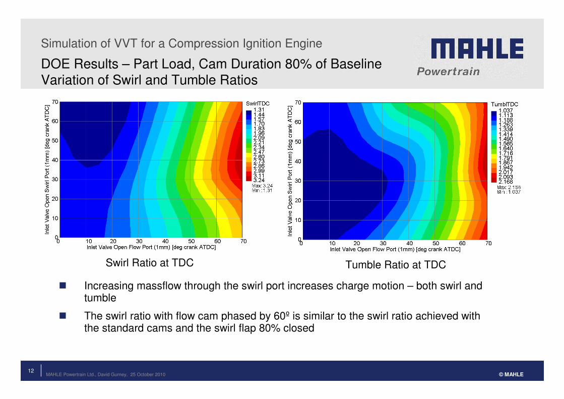
DOE Results – Part Load, Cam Duration 80% of Baseline Variation of Swirl and Tumble Ratios
Swirl Ratio at TDC Tumble Ratio at TDC
� Increasing massflow through the swirl port increases charge motion – both swirl and tumble
� The swirl ratio with flow cam phased by 60º is similar to the swirl ratio achieved with the standard cams and the swirl flap 80% closed

Simulation of VVT for a Compression Ignition Engine
13MAHLE Powertrain Ltd., David Gurney, 25 October 2010 © MAHLE
Part Load, Cam Duration 80% of Baseline Comparison of Massflow Through Valves
� The previous plots can be explained by
looking at the massflow through the valves
� Retarding either cam causes a large
increase in massflow through the fixed cam
earlier in the cycle
� The massflow through the port with the
retarded cam is greatly reduced
� At maximum phase angle, backflow does
occur through the retarded cam but, due to
the reduced duration, the massflow involved
is relatively small
� Longer cam durations give increasing levels
of backflow when phased
Expansion Exhaust Induction Comp
TDCNF TDCF
Swirl Port 60deg phase
Flow Port 60deg phaseFlow Port 60deg phase
Cams in Phase
Mas
sfl
ow
[k
g/s
]
-0.01
0.01
0.03
0.05
Lif
t [m
m]
0
2
4
6
8
10
Mas
sfl
ow
[k
g/s
]
-0.01
0.01
0.03
0.05
Lif
t [
mm
]
0
2
4
6
8
10
Lif
t [
mm
]
0
2
4
6
8
10
Ma
ss
flo
w
[kg
/s]
-0.01
0.01
0.03
0.05
CrankAngle [deg]
0 180 360 540 720
Exhaust Massflow Flow Port Massflow Swirl Port Massflow Exhaust Valve Lift Flow Valve Lift Swirl Valve Lift
Simulation of VVT for a Compression Ignition Engine
14MAHLE Powertrain Ltd., David Gurney, 25 October 2010 © MAHLE
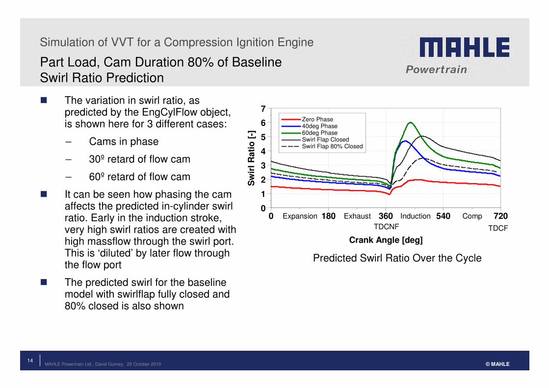
Part Load, Cam Duration 80% of Baseline Swirl Ratio Prediction
� The variation in swirl ratio, as predicted by the EngCylFlow object, is shown here for 3 different cases:
– Cams in phase
– 30º retard of flow cam
– 60º retard of flow cam
� It can be seen how phasing the cam affects the predicted in-cylinder swirl ratio. Early in the induction stroke, very high swirl ratios are created with high massflow through the swirl port. This is ‘diluted’ by later flow through the flow port
� The predicted swirl for the baseline model with swirlflap fully closed and 80% closed is also shown
Expansion Exhaust Induction Comp
TDCNF TDCF
Sw
irl
Ra
tio
[-]
0
1
2
3
4
5
6
7
Crank Angle [deg]
0 180 360 540 720
Zero Phase 40deg Phase 60deg Phase Swirl Flap Closed Swirl Flap 80% Closed
Predicted Swirl Ratio Over the Cycle

Simulation of VVT for a Compression Ignition Engine
15MAHLE Powertrain Ltd., David Gurney, 25 October 2010 © MAHLE
Peak Power, Scaled Durations from 80% to 100% of BaselineVolumetric Efficiency
� The aim of this work was to match the full load performance of the baseline engine with a valve lift profile that gave a benefit at the part load operating points
� Due to limitations of the compressor match and fuelling, this required the full load volumetric efficiency with CamInCam® to be similar to that of the baseline engine
� Reducing the cam duration does give reduced volumetric efficiency, but it can be increased with shorter durations by phasing CamInCam®. The 80% profile with 40º phasing gives a reduction in volumetric efficiency of just 3% from the baseline, which was considered acceptable
� The optimum cam timing moves closer to zero phasing with cams closer to the standard duration
Increasing Duration
Simulation of VVT for a Compression Ignition Engine
16MAHLE Powertrain Ltd., David Gurney, 25 October 2010 © MAHLE
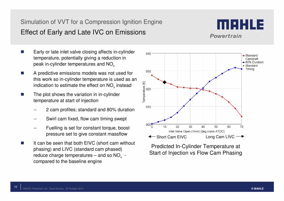
Effect of Early and Late IVC on Emissions
� Early or late inlet valve closing affects in-cylinder
temperature, potentially giving a reduction in
peak in-cylinder temperatures and NOx
� A predictive emissions models was not used for
this work so in-cylinder temperature is used as an
indication to estimate the effect on NOx instead
� The plot shows the variation in in-cylinder
temperature at start of injection
– 2 cam profiles; standard and 80% duration
– Swirl cam fixed, flow cam timing swept
– Fuelling is set for constant torque, boost
pressure set to give constant massflow
� It can be seen that both EIVC (short cam without
phasing) and LIVC (standard cam phased)
reduce charge temperatures – and so NOx -
compared to the baseline engine
Predicted In-Cylinder Temperature at
Start of Injection vs Flow Cam Phasing
Short Cam EIVC Long Cam LIVC

Simulation of VVT for a Compression Ignition Engine
17MAHLE Powertrain Ltd., David Gurney, 25 October 2010 © MAHLE
Effect of Early and Late IVC on Pumping Work
� The pumping work for a sweep of flow cam timing with standard and 80% duration cams is shown here. Again, EIVC is achieved with a reduced duration and no phasing, LIVC by standard duration with phasing
� The turbo match has been adjusted to compensate for the change in volumetric efficiency with different valve timings and this affects the pumping work. It can be seen how pumping losses are reduced, and even turned into positive work, with both EIVC and LIVC
� As with the in-cylinder temperature prediction, the optimum configuration varies with different speed and load points. At some EIVC gives the best results, at some LIVC, and no benefit was seen at others
Predicted PMEP vs Flow Cam Phasing
Short Cam EIVC Long Cam LIVC

18MAHLE Powertrain Ltd., David Gurney, 25 October 2010
Simulation of VVT for a Compression Ignition Engine
© MAHLE
Summary and Conclusions
� GT-Power has been used to investigate the application of CamInCam® to a passenger car diesel engine
– The model was correlated to full load and part load test data
– Swirl and tumble numbers have been calculated from flow bench tests and added in to the model as 3D maps to enable prediction of the effect of cam in cam on charge motion
� DOE’s were performed for variations of cam phasing and for different cam durations at full load and part load points
� CamInCam® is able to alter the proportion of massflow through the two inlet valves
– This allows the swirl and tumble characteristics to be altered
– Retarding the flow cam increases the flow through the swirl port. A 60º phase shift gives an in-cylinder swirl ratio greater than the standard cam with swirl flap 80% closed
� Variable cam duration allows the use of early or late inlet valve closing with the potential for reductions in both pumping work and NOx
� If CamInCam® is used with reduced duration cams, at full load the cams can be phased tominimise any reduction in airflow, allowing the cam profile to be optimised for part load


