Analysis and Tuning of Discrete MPFM Concept Thomas Hillman Lead Mechanical Engineer Aramco Americas Houston-Boston-Detroit, HRC2 Sensors Development Team November 17 th , 2021 Piston Capture Meter (PCM)
Transcript
Analysis and Tuning of Discrete MPFM Concept
Thomas Hillman
Lead Mechanical Engineer
Aramco Americas Houston-Boston-Detroit, HRC2 Sensors Development Team
November 17th, 2021
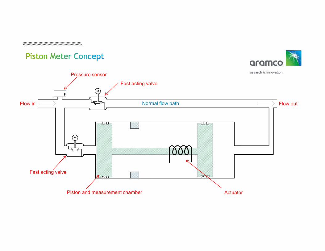
Piston Capture Meter (PCM)
• Coriolis meter brought to market in 1977.
• O&G industry investing in MPFM tech in early 80’s
• No meters in use until early 90’s
• Development by Schlumberger, Roxar/Emerson,
MPM, Framo, Pietro Fiorentini, and others
• Introduction of radioactive measurement methods
• Over 8000 MPFM’s in use worldwide today
Falcone, Gioia & Hewitt, G.F. & Alimonti, Claudio & Harrison, B.. (2013). Multiphase Flow Metering: Current Trends and Future Developments. Journal of Petroleum Technology. 54.
10.2118/71474-MS.
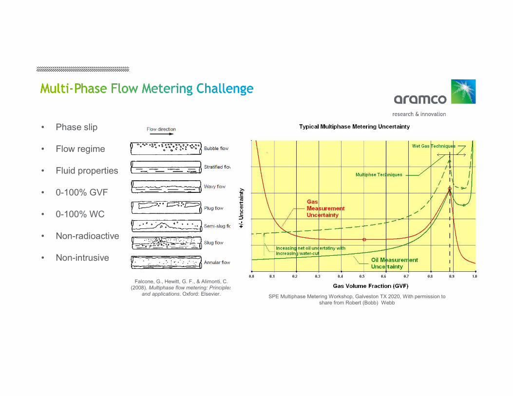
• Phase slip
• Flow regime
• Fluid properties
• 0-100% GVF
• 0-100% WC
• Non-radioactive
• Non-intrusive
Falcone, G., Hewitt, G. F., & Alimonti, C. (2008). Multiphase flow metering: Principles
and applications. Oxford: Elsevier. SPE Multiphase Metering Workshop, Galveston TX 2020, With permission to share from Robert (Bobb) Webb
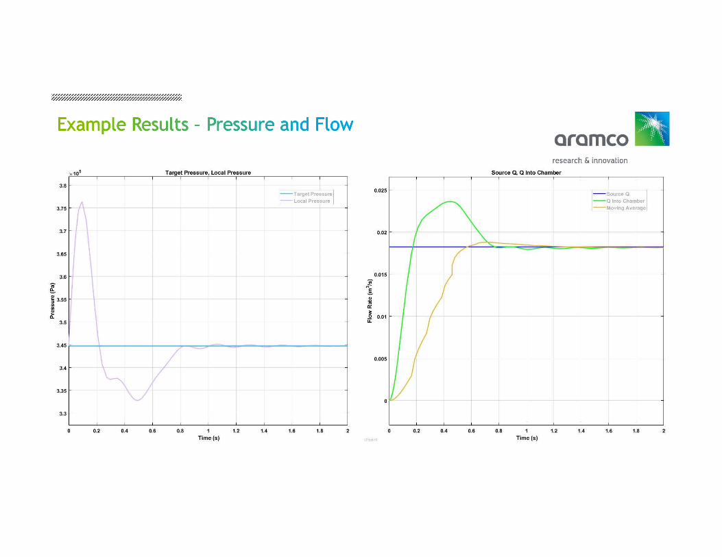
• Power of iteration with state space modelling in MATLAB
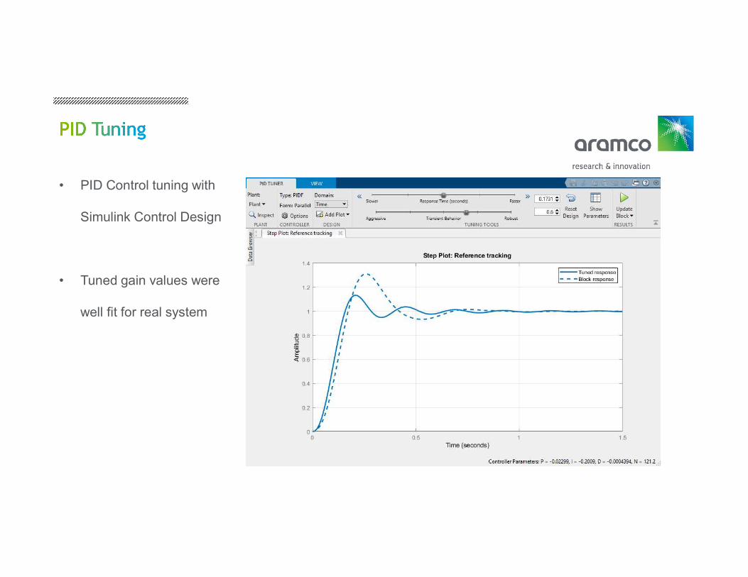
• Ability to tune PID system with Simulink Control Design
• Simulated results match expectations, validates concept
MathWorks products and toolboxes used: MATLAB R2019b Simulink V10.0 Simulink Control Design V5.4 Signal Processing Toolbox V8.3 DSP System Toolbox V9.9 Control System Toolbox V10.7