Simulation of Car Impact to Pedestrian Lower Extremity Influence of Different Car-Front Shapes and Dummy Parameters on Test Results Hirotoshi lshikawa( 1 ), Janusz Kajzer(2), Koshiro Ono( 1 ), Minoru Sakurai( 1) ( 1) Japan Automobile Research Institute, lnc., Kamira, Tsukuba, lbaraki 305, Japan. (2) Dept. of lnjury Prevention, Chalmers University of Technology, 41 2 96 Göteborg, Sweden. ABSTRACT Sled impact tests on mechanical substitutes of a pedestrian were conducted as a preliminary study for the purpose of developing a subsystem 1 test procedure for the assessment of car-front aggressiveness to pedestrian legs. Four mechanical substitutes of a pedestrian were used in the tests: the leg of a Rotationally Symmetrical Pedestrian Dummy (RSPD) as the representation of a subsystem, a HYBRID-II pedestrian dummy, a modified HYBRID-II pedestrian dummy equipped with a steel bar serving as knee joint, and a RSPD - HYBRID-HP combined dummy in which the lower part of the RSPD and the upper part of the HYBRID-HP were connected by a joint in such a way that the movements of the upper part were similar to those in cadaver tests. In the tests the following were evaluated: - Tue influence of vehicle shape on knee response and on vehicle impact forces; - Tue influence of the upper body mass on knee response and on vehicle impact forces; - The influence of bumper system on knee response, kinematics of pedestrian mechanical substitute and on vehicle impact forces; - Tue influence of pedestrian mechanical substitute characteristics on its kinematics, knee response and on vehicle impact forces. This paper describes a primary concept when subsystem test methods for the assessment of car- front aggressiveness to pedestrian legs in a car-pedestrian collision are considered. 1. INTRODUCTION A standardized test method for the evaluation of car-front aggressiveness to pedestrians in a car- pedestrian collision is being promoted by the EEVC ( 1 ), the NHTSA (2)(3) and the ISO. Currently. the ISO/TC22/SC10/WG2 (Pedestrian Impact Test Procedure) is considering a procedure for testing of car-front aggressiveness to pedestrian legs. Subsystems and full pedestrian dummies have been considered for a leg-to-bumper impact test. Tue test procedure should enable the evaJuation of the risk to pedestrian knee injuries, which very often cause permanent disability, the risk to bone fractures, and the risk to soft tissue injuries. A mechanical representation of the lower limb in form of an impactor with deformable knee joint developed by INRETS (Institut National de Recherche sur les Transports et leur Securite) in France is representative of a subsystem (4). The Rotationally Symmetrical Pedestrian Dummy (RSPD) developed at Department of lnjury Prevention, Chalmers University of Technology in Sweden and INRETS in France is probably the only pedestrian dummy equipped with a system for measuring the moments and forces in the lower extremities, esפcially at the knee joint (5). Mathematical simulations to compare a mechanical leg subsystem and dummy responses were conducted by INRETS. The capability of this subsystem to measure differences in the shape and the stiffness of car fronts which affect the risk to lower limb injuries was presented ( 4 ). In this report, the main criteria used for evaluating this risk were the knee bending moment and the knee 1 A subsystem is the mechanical representation of apart of the human body. Ishikawa et . - 1 -
Transcript
Simulation of Car Impact to Pedestrian Lower Extremity
Influence of Different Car-Front Shapes and Dummy Parameters on Test Results
( 1) Japan Automobile Research Institute, lnc., Kamira, Tsukuba, lbaraki 305, Japan. (2) Dept. of lnjury Prevention, Chalmers University of Technology, 41 2 96 Göteborg, Sweden.
ABSTRACT
Sled impact tests on mechanical substitutes of a pedestrian were conducted as a preliminary study for the purpose of developing a subsystem 1 test procedure for the assessment of car-front aggressiveness to pedestrian legs. Four mechanical substitutes of a pedestrian were used in the tests: the leg of a Rotationally Symmetrical Pedestrian Dummy (RSPD) as the representation of a subsystem, a HYBRID-II pedestrian dummy, a modified HYBRID-II pedestrian dummy equipped with a steel bar serving as knee joint, and a RSPD - HYBRID-HP combined dummy in which the lower part of the RSPD and the upper part of the HYBRID-HP were connected by a joint in such a way that the movements of the upper part were similar to those in cadaver tests. In the tests the following were evaluated:
- Tue influence of vehicle shape on knee response and on vehicle impact forces; - Tue influence of the upper body mass on knee response and on vehicle impact forces; - The influence of bumper system on knee response, kinematics of pedestrian mechanical
substitute and on vehicle impact forces; - Tue influence of pedestrian mechanical substitute characteristics on its kinematics, knee
response and on vehicle impact forces.
This paper describes a primary concept when subsystem test methods for the assessment of carfront aggressiveness to pedestrian legs in a car-pedestrian collision are considered.
1. INTRODUCTION
A standardized test method for the evaluation of car-front aggressiveness to pedestrians in a carpedestrian collision is being promoted by the EEVC ( 1 ), the NHTSA (2)(3) and the ISO. Currently. the ISO/TC22/SC 1 0/WG2 (Pedestrian Impact Test Procedure) is considering a procedure for testing of car-front aggressiveness to pedestrian legs. Subsystems and full pedestrian dummies have been considered for a leg-to-bumper impact test.
Tue test procedure should enable the evaJuation of the risk to pedestrian knee injuries, which very often cause permanent disability, the risk to bone fractures, and the risk to soft tissue injuries. A mechanical representation of the lower limb in form of an impactor with deformable knee joint developed by INRETS (Institut National de Recherche sur les Transports et leur Securite) in France is representative of a subsystem (4). The Rotationally Symmetrical Pedestrian Dummy (RSPD) developed at Department of lnjury Prevention, Chalmers University of Technology in Sweden and INRETS in France is probably the only pedestrian dummy equipped with a system for measuring the moments and forces in the lower extremities, especially at the knee joint (5).
Mathematical simulations to compare a mechanical leg subsystem and dummy responses were conducted by INRETS. The capability of this subsystem to measure differences in the shape and the stiffness of car fronts which affect the risk to lower limb injuries was presented ( 4 ). In this report, the main criteria used for evaluating this risk were the knee bending moment and the knee
1 A subsystem is the mechanical representation of a part of the human body.
Ishikawa et al. - 1 -
lateral bending angle. Tue knee shear force was excluded and the vehicle shapes only varied by means of four bumper heights, without changing the hood edge height and the bumper lead.
The setting up of standardized subsystem test methods for the assessment of car-front aggressiveness to pedestrian legs requires certain primary data obtained from experiments with subsystems and whole pedestrian dummies. Unfortunately, such data are not sufficiently available.
The purpose of our work has been to investigate primary data for the purpose of developing a subsystem test procedure for the assessment of car-front aggressiveness to pedestrian legs. Consequently, sied impact tests on mechanical substitutes of a pedestrian were carried out with the sied of varying vehicle shapes and with different bumper systems. This paper discusses the test methods for the assessment of car-front aggressiveness to pedestrian legs in a car-pedestrian accident.
2. METHODOLOGY
2.1 Test Conditions
Twenty-one tests were conducted in all. Tue test conditions are shown in Table 1. Four different mechanical substitutes of a pedestrian, four different front shapes of the sied, four different bumper systems, and two different impact velocities of the sied were used. Tue characteristics of the knee joint of the mechanical substitutes of a pedestrian were considered when impact velocities were chosen. Figure 1 shows a typical test setup.
2.2 Mechanical Substitutes of a Pedestrian
Four different mechanical substitutes of a pedestrian were used: 1) RSPD leg - the lower part of the RSPD (5), as the representation of a subsystem. 2) RSPD-HYB - the lower part of the RSPD and the upper part of the HYBRID-HP were connected by a ball joint in such a way that the movements of the upper body were similar to those of subjects in cadaver tests, 3) HYBRID-HP - conventional HYBRID-II pedestrian dumrny, 4) HYBRID-IIP-M - HYBRID-IIP modified and equipped with a steel bar serving as knee joint.
Cylindrical steel bars were used to represent the knee joint of the RSPD leg and the HYBRID-IIPM. These bars were chosen to undergo plastic deforrnation at a bending moment of 100 Nm.
Impact occurred on the right side of the dummy (for HYBRID-IIP-M, it occurred on the left side), which had been suspended and was released shortly before the impact. For HYBRID-HP and HYBRID-IIP-M, the first impacted leg was adjusted to support the whole body with the knee joint in an extended position and the remaining leg off the ground. Tue ground contact friction of the leg was considered to be the same as on a asphalt road.
2.3 Impact Sied and Bumper
Tue sied with variations in bumper height, hood edge height and bumper lead simulated the shape of the front of the car which referred to the average vehicle shape derived from accident analyses (6). Tue sied surfaces were covered with hard foam (polyethylene foam) which reproduced approximately the force deformation characteristics of a mass produced car. In all tests the hoodtop sloped down at a 5° angle to the horizontal plane.
Four different bumpers were attached to the sied as shown in Figure 2:
400 700 1nn STD BCH: Bumper center height HCH: Hood edge center height
Figure 1. Typical Test.
1) STD 2) D840 3) DB90
!!
(H)
1) STD :Standard bumper, currently used for a mass produced car.
Impact velocity (km/h)
1 5 & 24 24 24
15 & 24 24 24 24
15 & 24 24 24
1 5 15 & 24 1 5
B/L: Bumper lead
4)SFf
OOI
1
i !!! 1 1 i i O• 1 1 i
2) DB40 :Double bumper system, a 40 mm protruding structure added below the Standard bumper. 3) DB90 :Double bumper system, a 90 mm protruding structure added below the standard bumper. 4) SFr :Soft bumper made of polyethylene foam.
Figure 2. Bumper Systems.
Ishi.kawa et al.
- 3 -
!!j
§
2.4 Measurini Systems The data was acquired with an on-board digital recording system, and processed with filter class 180. The bending moment, shear force, and tensile force at the knee joint were calculated from the strain gauge signals. Tue resultant acceleration at the upper tibia (100 mm below the center of the knee joint) was measured by a three-axial accelerometer.
The impact force transducers were installed on the bumper and hood edge, and the force components were measured horizontally for the bumper and both horizontally and vertically for the hood edge. The hood edge impact angle was calculated from the horizontal and vertical impact force components when the hood edge impact force reached a maximum.
One high-speed camera (500 or 1000 frames/s) and two high-speed video cameras (one of 200 frames/s and the other of 500 frames/s) registered the movements of the mechanical substitutes of a pedestrian. During the high-speed film and video evaluation, the position of markers attached to the sled and mechanical substitutes of pedestrian were determined by means of a digitizer and an analyzing program. Knee lateral bending angle and head impact velocity were calculated during the impact sequence.
By means of an electric device able to calibrate the color density on the pressure-sensitive foil with the contact pressure, a Fuji film was used for calculation of the contact pressure at the bumper and the hood edge impact areas.
3. RESULTS
In five of the twenty-one tests made, the time at which the dummy was released was delayed, and thus the data from these tests may be used only for the analysis of a time window within 20 ms after impact. Therefore, the kinematics of the whole body in those five tests was not analyzed.
3.1 Influence of Vehicle Shape and Upper Body Mass on Knee Response
Figure 3 shows how the vehicle shape and upper body mass effect the knee response. Tue 3 ms peak bending moment, shear force, tensile force, and the peak lateral bending angle at the knee joint and the 3 ms peak acceleration at the upper tibia are plotted for various vehicle shapes. Results from the tests in which the upper body mass was included or excluded are presented in the same figure.
3.1.1 lnfluence of Vehicle Shape on Knee Response
The influence of the vehicle shape on knee response was analyzed from the test results obtained from the RSPD-HYB where upper body mass was represented.
When the bumper center height was lowered from 400 mm to 300 mm (nearer the center of gravity of the lower leg) the knee bending moment was reduced by 20 %. The influence of bumper lead and hood edge center height on the knee bending moment was slight.
When the bumper center height was lowered from 400 mm to 300 mm or when the hood edge center height was raised from 700 mm to 800 mm the knee shear force was reduced by more than 30 %. Tue increase of the bumper lead from 100 mm to 200 mm caused a 10 % increase of the knee shear force.
When the bumper center height was lowered from 400 mm to 300 mm, the knee tensile force was reduced by 45 % at a 15 km/h impact, and was increased by 25 % at a 24 km/h impact. When the bumper lead was increased from 100 mm to 200 mm or when the hood edge height was raised from 700 mm to 800 mm the knee tensile force was increased by more than 30 %.
Ishikawa et al. - 4 -
Upper body mass
24km/h -e--Yes · 0 - No Nm ISkm/h ....-ves - -6- · No
Hood edge center height Jlc.(lllll)j ( Bc.=4000Jn ) B/L= !OOIIlll
31 1nf1 uence of hood edge he i gh t
Figure 3. Influence of Vehicle Shape and Upper Body Mass on Knee Response.
When the bumper center height was lowered from 400 mm to 300 mm the knee lateral bending angle was reduced by more than 40 %. An increase of the bumper lead from 100 mm to 200 mm caused a 15 % reduction of the knee lateral bending angle, whereas an increase of the hood edge center height from 700 mm to 800 mm caused a 10 % increase of the knee lateral bending angle.
Tue influence of the vehicle shape on the tibia acceleration was slight.
3.1.2 Influence of Upper Body Mass on Knee Response
Tue influence of the upper body mass on knee response was analyzed by comparing the results from tests performed on mechanical substitutes of a pedestrian including the upper body mass to
Ishikawa et al. - 5 -
those in which the upper body mass was excluded.
When the upper body mass was excluded the knee-bending moment was decreased. This tendency became predominant at a 24 km/h impact when the bumper lead was increased from 100 mm to 200 mm and the hood edge center height was increased from 700 mm to 800 mm.
At a 15 km/h impact, with a bumper center height of 300 mm or 400 mm, the knee shear force, when the upper body mass was excluded, was 20 % lower than when the upper body mass was included. At a 24 km/h impact when the upper body mass was excluded, the knee-shear force was stable even when the bumper lead and hood edge height were varied. These results differ from those obtained when the upper body mass was included.
When the upper body mass was excluded, the knee tensile force showed the same tendency as the knee shear force. Namely when the upper body mass was excluded, the knee tensile force varied when the bumper height varied, but was stable for different bumper leads and hood edge heights.
The influence of the upper body mass on the knee lateral bending angle and tibia acceleration was also crucial.
3.2 Influence of Vehicle Shape and Upper Body Mass on Vehicle Impact Forces
Figure 4 shows how the vehicle shape and upper body mass effect the vehicle impact forces and impact angle. The peak bumper force, the peak hood edge force, and the hood edge impact angle are expressed for different vehicle shapes. Results from the tests in which the upper body mass was included or excluded are presented in the same figure.
„ u
Upper body mass
24km/h --e--ves · 0 · No kN 15km/h -.-ves • -6· · No
15 ..--------
� 10 ------·· 0 ... „
� 5 .. " ""
�----o�-�-�-� 200 kN
300 400 500
15 ,----------, „ u � 10
„ „ ..., „ '8 �··· � O '-
--�-�----'
200 deg.
300 400 500
� 90.----------, „ c "' - 60 u ::g_ Ei ·- 30 - -„ „ ...,
Figure 4. Influence of Vehicle Shape and Upper Body Mass on Vehicle Impact Forces.
lshikawa et al. - 6 -
3.2.1 Influence of Vehicle Shape on Vehicle Impact Forces Tue influence of the vehicle shape on the impact forces and impact angle was analyzed from the test results when the upper body mass was included.
At a 24 km/h impact, when the bumper center height was lowered from 400 mm to 300 mm, the bumper force was increased by 5 %. At the same impact velocity, when the hood edge height was raised from 700 mm to 800 mm, the bumper force was decreased by l 0 %. The influence of the bumper lead on the bumper force was slight.
At a 24 km/h impact, when the bumper center height was lowered from 400 mm to 300 mm, the hood edge force was increased by 45 %, when the bumper lead was increased from l 00 mm to 200 mm by 20 %, and when the hood edge center height was raised from 700 mm to 800 mm by 200 %.
At a 1 5 km/h impact, when the bumper center height was lowered from 400 mm t o 300 mm, the hood edge impact angle was increased by 15 %. At a 24 km/h impact, when the bumper center height was lowered from 400 mm to 300 mm, the hood edge impact angle was decreased by 45 %, when the bumper lead was increased from 100 mm to 200 mm by 10 %, and when the hood edge center height was raised from 700 mm to 800 mm by 45 %.
3.2.2 Influence of Upper Body Mass on Vehicle Impact Forces
The influence of the upper body mass on the impact force and impact angle was analyzed by comparing the results from tests performed on mechanical substitutes of a pedestrian including the upper body mass to those in which the upper body mass was excluded.
At a 24 km/h impact, when the upper body mass was excluded, the bumper force was reduced by 15 to 20 %. Note, at a 24 km/h impact, when the upper body mass was excluded, the bumper force was stable even when the bumper lead and hood edge height differed.
At a 24 km/h impact, when the upper body mass was excluded, the hood edge force varied according to the variations in the bumper lead and hood edge height. This tendency was almost the same as in tests when the upper body mass was included, but at a 700 mm hood edge height the force value was increased by 40 % and at an 800 mm hood edge height decreased by 20 % when the upper body mass was excluded.
For different bumper heights at a 15 km/h impact, the influence of the upper body mass on the hood edge impact angle was distinguished.
3.3 Influence of Bumper System on Knee Response. Pedestrian Dummy Kinematics and Vehicle Impact Forces
Figure 5 shows the influence of the bumper system on knee response, pedestrian dummy kinematics and vehicle impact forces at speed of 24 km/h.
For the double bumper system (DB90) compared to the standard bumper, the bending moment and tensile force about the knee were approximately 20 % lower, the shear force and the lateral bending angle at the knee and the tibia acceleration were more than 50 % lower.
For both double bumper systems (DB40 and DB90) compared to the Standard bumper, WAD (Wrap Around Distance), the bumper force and the hood edge impact angle tended to decrease, whereas the head impact velocity and the hood edge force tended to increase. These tendencies become predominant as the protrusion of the structure added below the Standard bumper was increased. Tue stiffness of this structure was estimated to be about 30 % of the standard bumper stiffness.
lshikawa et aJ. - 7 -
The soft bumper (SFT) highly decreased the knee shear force, the knee tensile force, the knee lateral bending angle and the tibia acceleration, but caused no remarkable decrease in the knee bending moment. The stiffness of the soft bumper was estimated to be about 65 % of the standard bumper stiffness, and thus did not comply with the low speed collision requirements for the bumper.
'
"' 50 c „ „
„ „ ::2 0 Slll 0040 0090
kN
„ "' � 0 � i � „ „ c "'
Slll CßlO 0090
„ "' � 0 .! � c „
„ „ c "' STD 0040 0090
deg. „90 -J. „ c „
_:60 - - · „.-�"' !! : �,Q30 „ „ c ""
Slll 0040 0090
SFT
SFT
SFT
SFT
Slll CßlO 0090 SFT
.21.s�----� i! � 1.0
.f o.s
j Slll CßlO 0090 SFT
ll!PaCt voloci IY : 24 km/h
131 Vehicle ---kN
15.------� „ "' � JO
STD 0040 0090 SFT kN 9 ,------�
Slll 0040 0090 SFT deg .
.! 90 ,-------, „ c „ ü 60 ;g_ .!
�30 „
STD 0040 0090 SFT
Vehiclo shapo: Bc.;400 nm Hc.;700 nm ß/I.; 100 nm
DJmri : RSl'l>-ffYB CRSPO 1 eg + H'lllR 10-11 P LR>er bodv) • : r;.., at llhich ciJmr>' roleased was delayed.
(Hoad ini>act volocity) llead ini>act velocity ratio ; ------
(Vehiclo ini>act volocity)
Figure 5. Influence of Bumper System on Knee Response, Pedestrian Kinematics and Vehicle Impact Forces.
3.4 Influence of Dummy Characteristics on Knee response. Pedestrian Dummy Kinematics and Vehicle Impact Forces. Figure 6 shows the influence of dummy characteristics on knee response, pedestrian dummy kinematics and vehicle impact forces.
At an impact velocity of 15 km/h, the knee lateral bending angle for the RSPD-HYB was approximately 20 % lower than that of the HYBRID-IIP-M, although these two dummies were provided with the same steel bar for the knee joint. This difference may be explained by the difference in the hip joint characteristics. The hip joint of the RSPD-HYB allowed for a 30-degree pendulum angle with low friction, whereas that of the HYBRID-IIP-M caused much more friction when struck from the side. The reaction force at the hip joint may cause a difference in the knee lateral bending angle.
The HYBRID-IIP and the HYBRID-IIP-M had the same type of leg, but not the same type of knee joint. The test results at an impact velocity of 15 km/h showed that the characteristics of the knee
lshikawa et al. - 8 -
joint affected the tibia acceleration.
The HYBRID-IIP and the HYBRIDIIP-M had the same type of hip joint but a different type of knee joint. These two dummies showed almost the same WAD. The WAD of the RSPD-HYB was greater than that of the HYBRID-IIP-M. These two dummies had a different type of hip joint and the same type of knee joint. These test results indicated that the influence of the hip joint characteristics on the pedestrian upper body kinematics was more crucial, compared with the influence of the knee joint characteristics.
The variations of the head impact velocity appear to be mainly due to the difference in hip JOint characteristics. Even the behavior of the dummy arms at hood top impact may influence the head impact velocity. Although in our tests, the influence of the dummy arms on the head impact velocity was minimized by constraining the wrists with a rope at the posterior side of the dummy.
--- III Pedostrian Leg-----.
RSl'!Hf18 Hll!RI0-1 IP HYllRIO-l IP-11
g ' 150 ,----------,
I� j � 100 ---
1; 50.--
l� i RSl'!Hf18 Hll!R 1 0-II P HYllR 1 0-11 P-11
..--- 121 Pedostrian Head ---. 1 m l 2.5 .---------1 2. 0 1�1.5 1 ;:: � 1.0 1 � 0. s l 1 g 1. 5
� 1.0 �
RSl'!Hf18 H1l!R 1 0-1 1 P HYllR 1 0-11 P-11
RSFIHflB H1l!R 10-11 P H'lm 10-11 P-11
...----- 131 Vehicle kN
15 ,----------, u � 10
u
RSl'!Hf18 HYllRIO-llP Hll!RIO-llP-11
kN 9,----------,
.!: 6 � � � � 3 -] ";::;·
RSFIHflB H1l!R 1 0-11 P H1l!R 1 0-1 1 P-11
doll . �00.----------,
� 60 --·· .!! �30
RSFIHflB HYllRID-1 IP HYBRI0-1 IP-M
lnpact velocitv: 15 Wh 1:1 24 km/h
Vehicle sr..>e: Sc"='OO m Hc" ... 700 m B!l�lOO nn
8uToe r : Standard buiiler
Head illl8Ct velocitv ratio
(Head iirpact velocity)
(VehicJe ilrll8Ct veloci tY}
Figure 6. Influence of dummy Characteristics on Knee Response, Pedestrian Kinematics and Vehicle Impact Forces.
The bumper force and the hood edge force varied according to the configuration of the pedestrian substitutes. The stiffness at the point of impact of the segment represented the leg, and the knee joint characteristics, may be the causes of these differences.
The hood edge impact angle also varied according to the configuration of the pedestrian substitutes. The essential parameter affecting the hood edge impact angle seems to be the knee joint characteristics. The RSPD-HYB and the HYBRID-IIP-M with the same type of knee joint and a different type of hip joint showed almost the same hood edge impact angle at a 15 km/h impact.
3.5 Relationship between Impact Forces. Tibia Acceleration and Contact Pressure
Figure 7 shows the relationship between the peak bumper force and the 3 ms peak tibia acceleration. If the same bumper system was used, there was a correlation between the bumper force and the tibia acceleration. If the bumper system was different, a different relationship seemed to obtain.
Figure 8 shows the relationship
Ishikawa et al.
�
(G) Q STD DSFf b. DB40 & DB90
150 ,-----------, AT =9.7 Fs R: 0.82
0
0 �--�-����� 0 5 10 15 Bumper force Fs (kN)
Figure 7. Relationship between Bumper
Force (Fs) and Tibia Acceleration (AT)
- 9 -
between the peak impact force and the contact pressure on the bumper. There was a good correlation between the bumper force and the contact pressure with different bumper systems. The contact pressure force increased remarkably when the bumper force exceeded 10 kN.
At the hood edge, the correlation between the impact force and the contact pressure was poor, this was probably due to the fact that the Fuji pressure sensitive film was pushed away from the hood edge by the tangential impact force at the hood edge, and thus failed to measure the contact pressure.
4. DISCUSSION
Q STD DSFT o..a::i (kgf/cm2 ) t:::. DB40 & DB90
80 � ::::1 Cll 60 Cll Cl) ..... 0..
ü 40 � E 0 u ..... 20 Cl) 0.. E ::::1 0 ro 0
Pa =0 .1 9 e 0.50F B R : 0.92
10 Bumper force Fs
15 (kN)
Figure 8. Relationship between Bumper
Force (fs) and Bumper Contact Pressure (iji)
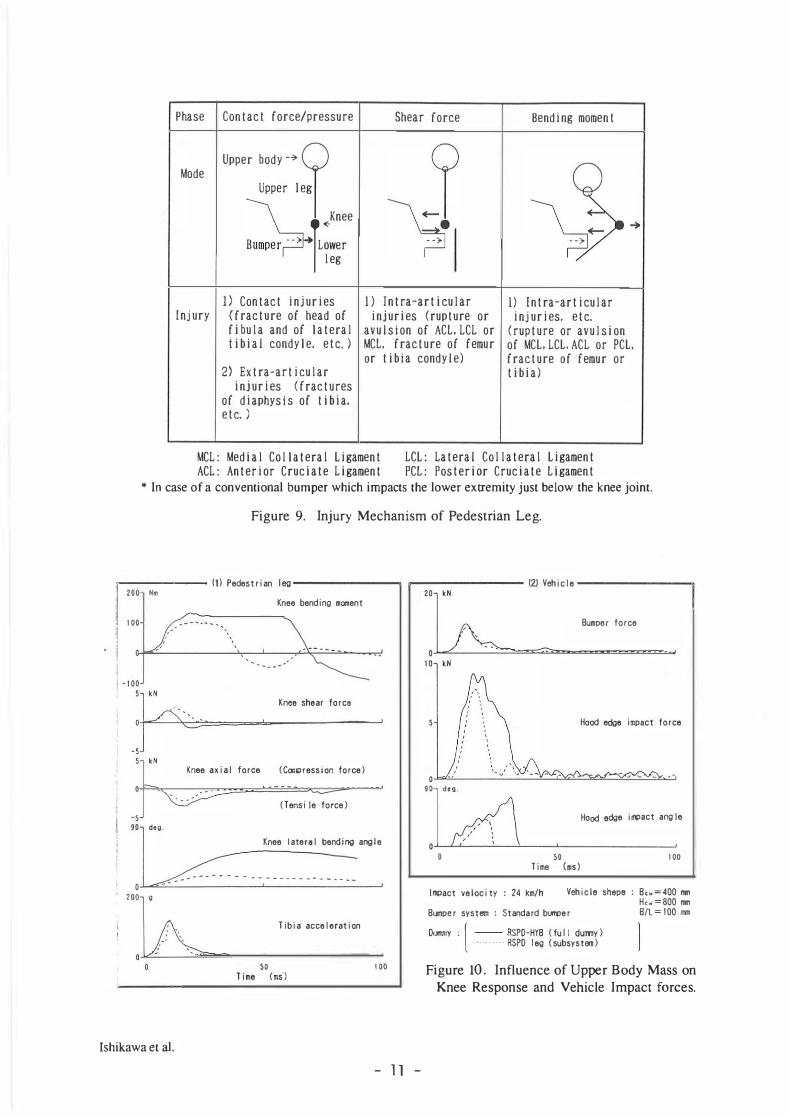
Figure 9 shows the injury mechanism of the lower leg in a pedestrian configuration after impact. There are three stages in the leg injury mechanism. The first stage is related to the impact phase, when contact force or contact pressure may generate injuries. The consequences of this force/pressure are injuries at the contact point (contact injuries) and extra-articular injuries (7). The second stage corresponds with the force transferred through the knee joint after the impact. The consequences of this force (shear force) are intra-articular injuries (7). The third stage is related to the bending moment transferred through the knee joint after the impact, which may cause knee injuries, especially injuries to the medial collateral ligament.
Figure 10 shows the time history of those parameters obtained from the two mechanical substitutes of pedestrian, one is the subsystem and the other the full dummy. Even the time window is limited to 0 - 30 ms after the impact, as all injuries occur during this time window (4)(7), the waveforms from these two substitutes differ in most of the parameters.
Within the scope of the present analysis it seems that the influence of the upper body mass on knee response is important. The influence of the upper body mass on the development of the impact forces is also obvious.
In a subsystem or dummy tests, it is necessary to measure injury related parameters simultaneously, and to date none of the substitutes used give an adequate description of the risks of lower leg and knee injuries.
With regard to the risk of leg injuries, a new subsystem test procedure should be developed. This subsystem should be able to measure essential injury related biomechanical parameters, such as forces and moments, under various test conditions.
Our test results show the necessity of discussing the influence of the upper body mass on the knee response. In order to develop a practical subsystem test procedure for the assessment of car-front aggressiveness to pedestrian legs, the influence of the upper body mass on the knee response should be further analyzed mathematically and experimentally by means of mechanical dumrnies or biological materials, with possible variations of test conditions, such as the vehicle shape, stiffness, impact velocity and so on.
lshikawa et al. - 10 -
Phase Contact force/pressure Shear force Bending moment
Upper body-> � Mode
Upper leg � Knee �-·F�, ...
leg
1) Contact injuries 1) Intra-articular 1) lntra-articular Injury (fracture of head of injuries (rupture or injuries, etc.
fibula and of lateral avulsion of ACL.LCL or (rupture or avulsion tibial condyle, etc.) MCL, fracture of f emur of MCL. LCL. ACL or PCL.
or tibia condyle) fracture of femur or 2) Extra-articular tibia)
ll!l>act veloci ty : 24 km/h Vehiclo shepo: Bcw=400 mm
Bllllper system : Standard bUl1'Cler
DllMlY : [ -- RSPD-HYB ( fu II dummy) .„ ...... RSPD leg (subsystem)
H,. =800 mm B/L=100m
Figure 10. Influence of Upper Body Mass on Knee Response and Vehicle Impact forces.
5. CONCLUSIONS
To obtain primary data for the construction of a subsystem test procedure for the assessment of car-front aggressiveness to pedestrian legs, twenty-one impact tests were conducted with different vehicle shapes, different bumper systems and different mechanical substitutes of pedestrian, at impact velocities of 1 5 km/h and 24 km/h. Tue results are summarized as follows.
1) Vehicle front shapes affected knee response. A subsystem test procedure should enable evaluation of the influence of the vehicle shape on knee response.
2) The upper body mass affected knee response of the mechanical substitutes of pedestrian. This tendency became predominant in particular with an increase in hood edge height. Tue test results show the necessity of discussing the influence of the upper body mass on knee response.
3 ) The double bumper (protruding structure added below the standard bumper) effectively decreased the bending moment and shear force about the knee joint.
4) The soft bumper decreased the knee shear force, but it was not effective for decreasing the bending moment about the knee.
5 ) The influence of the hip joint characteristics on the pedestrian substitutes upper body kinematics was distinguished, compared with the influence of the knee joint characteristics.
6) The hood edge impact force and hood edge impact angle were varied by the knee joint characteristics.
7) There was an good correlation between the bumper force and the contact pressure of different bumper systems.
8) There appeared to be a different relationship between the bumper force and the tibia acceleration when different bumper systems were used.
Our s ied impact tests were conducted as a preliminary study for the purpose of developing a subsystem test procedure for the assessment of car-front aggressiveness to pedestrian legs, and a further study will be necessary.
REFERENCES
!/ Harris J., A Study of Test Methods to Evaluate Pedestrian Protection for Cars, Proceedings of the 1 2th International Technical Conference on Experimental Safety Vehicles, Göteborg, May 1989, pp. 1217-1226.
2/ Kessler J., Monk M., NHTSA Pedestrian Head Injury Mitigation Research Program - Status Report, Proceedings of the l 2th International Technical Conference on Experimental Safety Vehicles, Göteborg, May 1989, pp. 1226-1237.
3/ Elias J., Monk M., NHTSA Pedestrian Thoracic Injury Mitigation Program - Status Report, Proceedings of the l 2th International Technical Conference on Experimental Safety Vehicles, Göteborg, May 1989, pp.1237-1244.
4/ Cesari D., Alonzo F., Matyjeski M., Subsystem Test for Pedestrian Lower Leg and Knee protection, The 13th International Technical Conference on Experimental Safety Vehicles, Paris, France, November 199 1 .
5 / Aldman B . , Kajzer J., Cesari D . , Bouquet R . , Zac R., A New Dummy for Pedestrian Test, The lOth International Technical Conference on Experimental Safety Vehicles, Oxford, Englan� July 1985, pp.176-185.
6/ Ishikawa H., Yamazaki K., Ono K. and Sasaki A., Current Situation of Pedestrian Accidents and Research into Pedestrian Protection in Japan, The 1 3th International Technical Conference on Experimental Safety Vehicles, Paris, France, November 199 1 .
7/ Kajzer J., Cavallero C., Ghanouchi S . , Bonnoit J., Ghorbel A., Response o f the Knee Joint i n Lateral Impact: Effect of Shearing Loads, IRCOBI International Conference, Bron, France, September 1990, pp.293-304.