SIMULATION OF LNAPL MIGRATION AND REMEDITION AT A PETROLEUM REFINERY SITE NOR FARINA NADZIF A project report submitted in partial fulfillment of the requirement for the award of the degree of Master of Engineering (Civil - Hydrology and Water Resources) Faculty of Civil Engineering UniversitiTeknologi Malaysia JUNE 2015
Transcript
SIMULATION OF LNAPL MIGRATION AND REMEDITION AT A PETROLEUM REFINERY SITE
NOR FARINA NADZIF
A project report submitted in partial fulfillment of the
requirement for the award of the degree of
Master of Engineering (Civil - Hydrology and Water Resources)
Faculty of Civil Engineering
UniversitiTeknologi Malaysia
JUNE 2015
iii
Dedicated to my beloved family
iv
ACKNOWLEDGEMENTS
Foremost, I would like to express my deepest gratitude to my fellow
postgraduate research partner, Nor AsniAzizan, and my technical supervisor, Dr.
Samira AlbatiKamaruddin, for their time, motivation andtechnical advice in the
preparation of this project report especially for the application of the T2VOC
numerical model used for this study. This study is under the support of the Ministry
of Education (MOE) and UniversitiTeknologi Malaysia (UTM) sponsorship through
the research university grant (GUP) for the Project No. 00K47 and 10J93 awarded to
Dr. Samira AlbatiKamaruddin. Concurrently, my sincere gratitude goes to my main
supervisor, Dr. Zulhilmi Ismail, for the continuous support and understanding in the
deliverable of this study.
I am also grateful and indebted to all of my course lecturers, in the
Department of Civil Engineeringwhose expertise, immense knowledge and advice,
added considerably to my graduate experience.
Last but not least, my sincere appreciation also extends to my
familyespecially my parents, Nadzif Ismail and Faridah Adam, who have provided
assistance at various occasions. Without their continuous support and interest, this
project report would not have been the same as presented here.
v
ABSTRACT
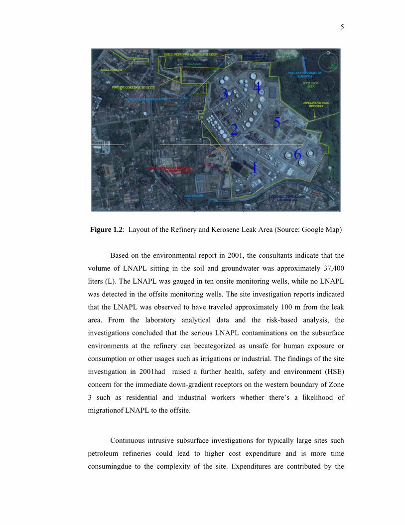
This study presents the results of simulation for the migration of light non-
aqueous phase liquid (LNAPL) contamination at Port Dickson petroleum refinery
and a remediation by steam injection using T2VOC numerical model. A kerosene
leak of 20 years period from the distributing pipelines has caused a serious LNAPL
contamination in the subsurface environments. Site investigations were conducted to
identify the source of leak and to delineate the contaminations plumes. The concern
raised was whether the LNAPL has travelled offsite and has reached the subsurface
environments of the down-gradient residential areas. The support tools considered in
this study for delineation and remedial solution are based on theexisting site
investigations and the application of the numerical model. Numerical simulation will
investigate the distribution of LNAPL and remediation within economical and
shorter timeline, in response to management decision. In this study, T2VOC is used
to simulate a ‘three-phase non-isothermal single component flow’ in a partially
saturated homogeneous media for the injection of 876.5 kg of o-xylene (component
of kerosene) in a two-dimensionalmodel. The model generated a distribution of
LNAPLat a distance of 10 m for 5 years of injection period, while site investigation
showed a migration plume of 100 m for 20 years of leak period. Verification with the
formulation computed a plume length of 19.9 m. The numerical simulation results
are underestimated compared to the site investigation data, although the distribution
showed the same behavior for both of methods with time.Based on the results of the
numerical simulation and validation with site investigation data, the LNAPL
distribution in the subsurface of the refinery was unlikely to migrate offsite to the
residential area. While, the simulation of remediation with steam injection showed
that 90% of the LNAPL saturation was removed in 20 days of treatment. The result
has therefore demonstrated the effectiveness of steam injection process for this study.
vi
ABSTRAK
Kajian ini membentangkan hasil simulasi pencemaran minyak atau cecair
bukan akues ringan (LNAPL) di kilang penapisan petroleum Port Dickson dan
kaedah pemulihan pencemaran melalui suntikan stim menggunakan model T2VOC.
Kebocoran saluran paip penghantaran minyak tanah (kerosene) yang berlaku selama
20 tahun telah menyebabkan pencemaran yang serius kepada tanah dan air tanah.
Siasatan persekitarantelah dijalankan untuk mengenalpasti punca kebocoran dan
menyiasat pergerakan pencemaran air tanah. Persoalan adalah sama ada
LNAPLdalam air tanah telah mengalirdi bawah kawasan perumahan bersebelahan
kilang. Dalam kajian ini, model T2VOC beserta kerja siasatan persekitaran
digunakan sebagai alat sokongan untuk memilih kaedah pemulihan yang sesuai bagi
kawasan yang tercemar. Kajian simulasi menyiasat pengaliran LNAPL dan
pemulihan dalam tempoh lebih pendek dan jimat berbanding kerja siasatan lanjutan.
Model simulasi dua-dimensi menggunakan T2VOC telahmenghasilkan pergerakan
minyak dalam sistem ‘satu komponen tiga-fasa tanpa sesuhu’bagi permukaan tanah
sejenis bagi suntikan 876.5 kg o-xylene (komponen minyak tanah). Pergerakan
LNAPL telah dilihat pada jarak 10 m selama 5 tahun tempoh suntikan, manakala
siasatan persekitaran sedia ada menunjukkan pergerakan LNAPL pada jarak 100 m
selama 20 tahun tempoh kebocoran. Pengiraan formula menunjukkan LNAPL
mengalir pada jarak 19.9 m. Keputusan simulasi adalah kurang berbanding dengan
data penyiasatan sedia ada. Walau bagimanapun, pengerakan LNAPLadalah dalam
tingkah yang sama untuk kedua-dua kaedah. Berdasarkan keputusan simulasi
dansiasatan persekitaran, LNAPL di dalam tanah dan air tanahtidak mengalir keluar
dari kilang ke kawasan perumahan. Simulasi pemulihan dengan suntikan stim
menunjukkan 90% daripadaLNAPL telah dirawat dalam tempoh 20 hari. Ini telah
menunjukkan keberkesanan proses suntikan stim dalam kajian ini.
vii
TABLE OF CONTENTS
CHAPTER TITLE PAGE
DECLARATION ii
DEDICATION iii
ACKNOWLEDGEMENTS iv
ABSTRACT v
ABSTRAK vi
TABLE OF CONTENTS vii
LIST OF TABLES x
LIST OF FIGURES xi
LIST OF ABBREVIATIONS xii
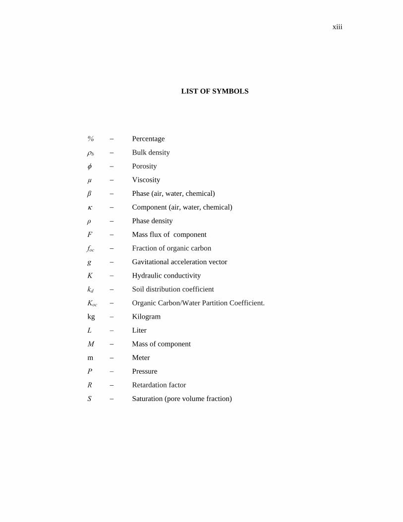
LIST OF SYMBOLS xiii
LIST OF APPENDICES xiv
1 INTRODUCTION 1
1.1 General 1
1.2 Statement of the Problem 4
1.3 Aim and Objectives of the Study 7
1.4 Scope of the Study 7
1.5 Significance of the Study 9
2 LITERATURE REVIEW 10
2.1 LNAPL Distribution in the Subsurface Environment 10
viii
2.1 LNAPL Distribution in the Subsurface Environment 10
2.2 Remediation Technology for LNAPL-Contaminated
Sites
14
2.3 Numerical Model and Its Application 21
2.4 Previous Studies using T2VOC Model 22
2.5 T2VOC Model Development 24
2.5.1 Physical Processes, Assumptions and
Limitations of T2VOC
26
2.5.2 Governing Equations 29
2.5.3 The Initial and Boundary Conditions 32
2.5.4 The Primary and Secondary Variables 33
3 RESEARCH METHODOLOGY 38
3.1 General 38
3.2 Collection of Site Investigation Data 39
3.2.1 Site Geology and Hydrogeology 43
3.2.2 Site Investigation Finding 45
3.3 Simulation of LNAPL Distribution and
Remediation
4
3.3.1 T2VOC Input Formats 46
3.3.2 T2VOC Output Formats 49
3.3.3 Simulation Process 49
4 RESULTS AND DISCUSSIONS 52
4.1 Simulation of LNAPL Distribution (Step 1 - 3) 52
4.2 Simulation of Remediation with Steam Injection
(Step 4)
54
4.3 Validation and Verification of Simulation Model 57
4.3.1 Validation 57
4.3.2 Formula Verification 59
5 CONCLUSION AND RECOMMENDATION 62
5.1 Conclusion 62
ix
5.2 Recommendation 64
REFERENCES
APPENDICES
66
73
x
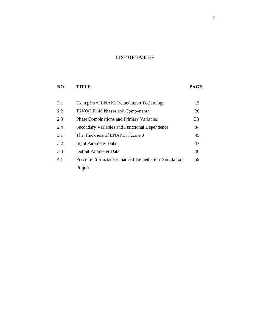
LIST OF TABLES
NO. TITLE PAGE
2.1 Examples of LNAPL Remediation Technology 15
2.2 T2VOC Fluid Phases and Components 26
2.3 Phase Combinations and Primary Variables 33
2.4 Secondary Variables and Functional Dependence 34
and Site Investigation Reports for Port Dickson Refinery. Adegbola, A. A., Dare, A. A., Ajayi, J. P., Alimi, A.A., Popoola, O. O And Afolabi.,
J. K. (2014). Numerical and Experimental Investigation of Steam Stripping Of LNAPL-Contaminated Soils.International. Journal of Engineering Research And Applications. 4: 01-10
Agency for Toxic Substances and Disease Registry (ATSDR) (2005).Toxicological
Profile for Jet Fuels JP-4 and JP-7.Report submitted to USEPA. Alvarez, J. and Han, S. (2013). Current Overview of Cyclic Steam Injection
Process.Journal of Petroleum Science Research. 2 (3): 116-127. American Petroleum Institute (API), Petroleum HPV Testing Group (2010).
Kerosene/Jet Fuel Category Assessment Document. American Petroleum Institute (API) (2007). LNAPL Distribution and Recovery
Model (LDRM). Volume 1: Distribution and Recovery of Petroleum Hydrocarbon Liquids in Porous Media. API Publication 4670.
American Society for Testing and Materials (ASTM) (2007).Standard Guide for
Development of Conceptual Site Models and Remediation Strategies for Light Non-Aqueous Phase Liquids Released to the Subsurface. Designation: E2531– 06. ASTM Committee E50 on Environmental Assessment, Risk Management and Corrective Action, DOI: 10.1520/E2531-06E01.
Asadollahfard, G., Khodadi, A. and Javadifar, N. (2013).UTCHEM Model
Application For Prediction Of Crude Oil Removal From Contaminated Sand Columns. Journal of theGeological Society of India. 82(6): 712-718.
Beller HR, Ding W-H, Reinhard M (1995).By-Products of Anaerobic Alkylbenzene
Metabolism Useful as Indicators of in Situ Bioremediation. Environ Sci Technology 29: 2864-2870.
Brost, E.J., and DeVaull, G.E., (2000).Non-Aqueous Phase Liquid (NAPL) Mobility
Limits in Soil.Soil and Groundwater Research Bulletin (9).
67
Center for Petroleum and Geosystem Engineering (2000).Volume II: Technical Documentation for UTCHEM-9.2, A Three-Dimensional Chemical Flood Simulator. Texas: The University Of Texas Austin.
Charbaneau, R. J. (2000). Groundwater Hydraulics and Pollutant Transport. Upper
Saddle River, New Jersey. Prentice-Hall Inc. Class, H., Helmig, R. (2002).Numerical Simulation of Non-Isothermal Multiphase
Multicomponent Processes in Porous Media.Applications for the Injection of Steam and Air. Advances in Water Resources 25: 551–564.
Coffey Partners International Pty Ltd (1997). Groundwater Investigations for Port
Dickson Refinery. Committee on Ground Water Cleanup Alternatives (CGWCA) (1994).Alternatives
for Ground Water Cleanup.National Academy Press, Washington, DC. Dunlap L.E. and Beckman, D.D. (1988).Soluble Hydrocarbon Analysis from
Kerosene/Diesel Type Hydrocarbon.Proceedings of Association of Ground Water Scientist and Engineers and American Petroleum Institute.Amoco Corporation, Tulsa Oklahoma.Conference on Petroleum Hydrocarbon and Organic Chemicals in Groundwater. Pp. 37 – 45.
Environmental Resources Management (M) Sdn. Bhd. (2001).On and Off-Site
Delineation Investigation of Kerosene Spill, and Completion of the Groundwater Quality Monitoring Well System and Kerosene Spill Assessment for Port Dickson Refinery.
Eugene, R. (2012). Application of Environmental Aquatic Chemistry: A Practical
Guide. Third Edition.CRC Press, Taylor and Francis Group. Fagerlund, F., Niemi, A. (2003).Multi-Constituent Modelling of a Gasoline Spill
Using the T2VOC Numerical Stimulator.Department of Earth Sciences, Uppsala University, Sweden.
Fagerlund, F. (2006).Experimental and Modeling Studies on the Spreading on Non-
Aqueous Phase Liquids in Heterogenous Media. Digital Comprehensive Summaries of Uppsala Dissertations from the Faculty of Science and Technology 259:6.
Fagerlund, F., Niemi, A. and Illangasekare, T.H. (2008).Modelingof Nonaqueous
Phase Liquid (NAPL) Migration in Heterogeneous Saturated Media: Effects of Hysteresis and Fluid Immobility in Constitutive Relations. Water Resources Research.44(3).
Falta, R. W. (1990). Multiphase Transport of Organic Chemical Contaminants in the Subsurface.University of California, Berkeley.
Falta, R. W., Pruess, K., Finsterle, S., and Battistelli, A. (1995).T2VOC User’s Guide, Report LBL-36400, UC- 400, Lawrence Berkeley National Laboratory, Berkeley. California.
68
Feenstra, S., Mackay, D.M., and Cherry, J.A. (1991).A Method for Assessing Residual NAPL based on Organic Chemical Concentrations in Soil Samples Groundwater Monitoring. Rev. 11(2): 128-136.
of DNAPLS during Steam Enhanced Extraction. Proceedings of First International Conference on Remediation of Chlorinated and Recalcitrant Compounds, Monterey, USA. Battelle Press, Columbus, Ohio, pp. 31–36.
Golder Associates (2008).Guidance on Assessment of Light Non-Aqueous Phase
Liquid Mobility for Site Classification Purposes in British Columbia, Report Submitted to BC Ministry of Environment, 45 p.
Gudbjerg J., Sonnenborg, T.O., and Jensen, K.H. (2004).Remediation of NAPL below
the Water Table by Steam-Induced Heat Conduction. Journal of Contaminant Hydrology 72[1- 4]: 207-25.
Ho, C.K. and Udell, K.S. (1992). An Experimental Investigation of Air Venting of
Volatile Liquid Hydrocarbon Mixtures from Homogeneous and Heterogeneous Porous Media.Journal of Contaminant Hydrology 11: 291– 316.
Huntley, D. (2000). Analytic Determination of Hydrocarbon Transmissivityfrom
Baildown Tests. Ground Water, Vol. 38, No. 1, Pp.46-52. Jeongkon, K., and Corapcioglu, M.Y. (2003).Modeling Dissolution and
Volatilization of LNAPLSources Migrating on the Groundwater Table. Journal of Contaminant Hydrology 65: 137– 158
Johnson, R.L., Bagby,W., Perrott, M., and Chen, C. (1992a).Experimental
Examination of Integrated Soil Vapor Extraction Techniques Conference.on Petroleum Hydrocarbons and Organic Chemicals in Ground Water: Prevention, Detection, and Restoration, National. Ground Water Association, Dublin, OH, 441-452.
Katyal, A. K., Kaluarachchi, J.J., Parker, J.C., Cho, J.S. and Swaby, L.G.
(1991).MOFAT: A Two Dimensional Finite Element Program for Multiphase Flow and Multicomponent Transport (No. EPA/600/2-91/020). Ada, Oklahoma: RSKERL USEPA
Karapanagioti, H.K., Gaganis, P., and Burganos, V.N (2003).Modeling Attenuation
of Volatile Organic Mixtures in the Unsaturated Zone: Code and Usages. Environmental Modelling and Software, 18(4), 329-337
Kempa, T., Marschalko, M., Yilmaz, I., Lacková, E., Kubečka, K., Stalmachová, B.,
Bouchal, T., Bednárik, M., Drusa, M., and Bendová M. (2013).In-Situ Remediation of the Contaminated Soils in Ostrava City (Czech Republic) by Steam Curing/Vapor.Engineering Geology 154: 42–55.
69
Kling, T., Korkealaaksoa, J., and Saarenpääb, J. (2004).Application of Nonisothermal Multiphase Modeling to In Situ Soil Remediation in Söderkulla.Vadose Zone Journal 3:901-908
Letícia, A., Bernardez, R.T., René, L., and Richard, M. (2009).Simulating the
Injection of MicellarSolutions to Recover Diesel in a Sand Column. Journal of Contaminant Hydrology 103: 99–108
MDH Engineered Solutions (2005). Evaluation of Computer Models For Predicting
the Fate And Transport Of Hydrocarbons in Soil and Groundwater. MDH Engineered Solutions Corporation.
Mendoza, C.A., and McAlary, T.A. (1989).Modeling of Groundwater Contamination
Caused by Organic Solvent Vapors. Ground Water, 28(2): 199-206. Mortensen, A.P., Jensen, K.H., Sonnenborg, T.O., and Arvin, E. (2000).Laboratory
and Numerical Investigation of Air Sparging using MTBE as a Tracer. Ground Water Monitoring and Remediation 20[4]: 87-95.
Naidu, R. (2013).Recent Advances in Contaminated Site Remediation. Water Air Soil
Pollution 224:1705 Newell, C.J., Steven D.A., Randall R.R., and Scott G.H. (1995).Light Non-Aqueous
Phase Liquid. Groundwater Issue.Superfund Technology Support Center forGround Water.U.S. Environmental Protection Agency.
Schmidt, R., Gudbjerg, J., Sonnenborg, T.O., Jensen, K.H. (2002). Removal of NAPLs from the Unsaturated Zone using Steam: Prevention of Downward Migration by Injecting Mixtures of Steam and Air. Journal of Contaminant Hydrology 55: 233– 260.
Sims, R.C., (1990). Soil Remediation Techniques at Uncontrolled Hazardous Waste
Sites, J. Air Waste Manage. Assoc., 40(5): 704-730. Tzovolou, D. N., Aggelopoulos, C.A, Theodoropoulou, M.A., Tsakiroglou, C.D.
(2011). Remediation of The Unsaturated Zone Of NAPL-Polluted Low Permeability Soils with Steam Injection: An Experimental Study. J Soils Sediments 11:72–81
U.S. Environmental Protection Agency (USEPA) (1992a).Dense Nonaqueous Phase
Liquids – A Workshop Summary, Dallas, Texas, April 16-18, 1991, EPA/ 600/R-92/030, U.S.EPA, R.S. Kerr Environ. Res. Lab., Ada, OK, 81 pp.
U.S. Environmental Protection Agency (USEPA) (1995).In Situ Steam Enhanced
U.S. Environmental Protection Agency (USEPA) (1996).Soil Screening Guidelines.
User Guide EPA/140/R-96/018 U.S. Environmental Protection Agency (USEPA) (1988).Guidance on Remedial
Actions for Contaminated Ground Water at Superfund Sites.
U.S. Environmental Protection Agency (USEPA) (2000).Engineered Approaches to In Situ Bioremediation of Chlorinated Solvents: Fundamentals and Field Applications.
U.S. Environmental Protection Agency (USEPA) (2004).Cleaning Up the Nation’s Waste Sites: Markets and Technology Trends. Office of Soild Waste and Emergency Response.EPA 542-R-04-015.
Waduge, W.A.P., Soga, K., and Kawabata, J. (2004).Effect of NAPL Entrapment Conditions on Air Sparging Remediation Efficiency. Journal of Hazardous Materials, 110 (1-3), 173-183.
Weiner, E.R. (2000). Applications of Environmental Chemistry: A Practical Guide For Environmental Professionals. CRC Press LLC, Florida.
Yeh, G.T., Hansen, S.S., Lester, B., Strobl, R., and Scarbrough, J.
(1992).3DFEMWATER/3DLEWASTE: Numerical Codes for Delineation
71
Wellhead Protection Areas in Agricultural Regions Based on the Assimilative Capacity Criterion USEPA.