Research ArticleSimulation Study of the Roof Fracture Pattern of a HorizontalSublevel Caving in a Steeply Inclined Thick Coal Seam
Xin Kang ,1 Sheng-li Yang,2 Ping Zhan,3 and Liang-hui Li2
1College of Civil Engineering, Tongji University, Shanghai 200092, China2School of Energy and Mining Engineering, Ching University of Mining and Technology-Beijing, Beijing 100083, China3Shanxi Lu’an (mining) Group Co., Ltd., Changzhi 046204, China
Application of a horizontal section top-coal caving in a steeply inclined thick coal seam not only effectively resolves the problem ofthe large dip angle of the coal seam and slipping and dumping of mining equipment but also significantly reduces the tunneldrivage ratio and improves the extraction yield. In addition, it allows for a safe and efficient mining from a steeply inclined thickcoal seam. In this paper, the roof fracture pattern of a steeply inclined thick coal seam has been studied by a similar simulationexperiment.-e results of the simulation are consistent with those of the numerical calculations, thus verifying the accuracy of thesimulation. -e experimental simulation results show that the roof can form a step-like toppling failure pattern after drawing thecoal, and it is difficult to release a triangular coal mass near the floor, which is the main concentration area of coal loss. -enumerical simulation results show that, with the excavation of the coal seam, the rock mass around the goaf produces plasticfailure, and the damage is mainly concentrated in the roof area. -e upper part of the goaf mainly shows a tensile failure, while theother areas mainly show yield failure.
1. Introduction
A steeply inclined coal seam refers to a coal seam that has aninclination angle between 45° and 90°. Such a large anglearises due to a series of complex geological structures, suchas folds or faults, which have been formed by violent crustalmovements over a long period of time. Although the overallproportion of coal seams in such conditions is small, movingtoward west will be the focus of coal resource developmentin our country for quite a long time to come as the coalreserves in eastern China are running out and coal mining incentral China has led to environmental degradation. Due tothe special geological conditions in western China, more andmore mines will inevitably face the problem of miningsteeply inclined thick coal seams. -us, it is of great sig-nificance for rational development and utilization of re-sources to study the mining methods of coal seams underthis condition.
For steeply inclined thick coal seams having thicknessabove 10m, the horizontal sublevel caving method hassignificant advantages: it not only greatly reduces the tun-neling rate but also improves the production and benefits. Itis more suitable than other methods and should be adoptedwhenever possible [1]. However, the method will repeatedlydisturb the overlying strata and goaf, aggravating theirdamage, seriously threatening the safety of undergroundlaborers, and making it increasingly difficult to ensure safemining. In addition, because of the large dip angle of the coalseam and a large concentration of closely located miningsites, the method will aggravate surface movement anddeformation, and surface subsidence will become severe.Moreover, water bodies, railways, and other structures lo-cated on the surface will be seriously damaged due to theimpact of subsidence areas.
Scholars from the country and abroad have done a lot ofresearch in this field. Toke proposed the cantilever beam
HindawiAdvances in Civil EngineeringVolume 2020, Article ID 8370634, 10 pageshttps://doi.org/10.1155/2020/8370634
hypothesis in 1916, in which, as a continuous medium, theroof layer above the working face and goaf could be regardedas a beam with one end fixed in the rock mass and the otherend in the overhanging state. Qian Minggao [2] put forwarda mechanical model of “masonry beam,” which provides atheoretical basis for controlling the pressure in the stope andthe design of the support. Song Zhenqi put forward thehypothesis of “transfer rock beam,” according to which, onlya part of the force, generated during the movement of therocking beam, acts on the support and the force is deter-mined by the control requirements of its movement. Jiachenet al. [3, 4] have done a lot of work on the roof fracturepattern of steeply inclined thick coal seams and put forwardthe “toppling-slumping” failure mode. Yang et al. [5]havealso done a lot of work in this regard, believing that thesliding phenomenon will occur on the floor and thedownward displacement will increase after the failure ofoverburden, which will impact the top coal and residualwaste rock in the goaf.
After studying the roof structure of a fully mechanizedcaving face, Wu [6]pointed out that the caving character-istics of the top coal and direct roof are such that, for acomplicated coal seam structure and a thick layer of top coal,an arch balanced structure, namely, a coal-coal structure,can be formed between the caving top coal in the goaf andthe uncaving top coal above the support, which is not easy tobe destroyed by humans.
Based on the theory of stress arch shell, Wang et al. [7]put forward an evolutionary discriminant coefficient todetermine the evolution characteristics of stress arch shell inthe overlying rock. Yin et al. [8]found that the position of themiddle and bottom portion of the goaf is the maximumdeflection point of the inclined thin plate on four sides, andbased on this, they established the mechanical model of theoverlying rock deformation for a high-dip coal seam. Usingthe thin plate theory, Zhang [9]analyzed the stress distri-bution characteristics and fracture mechanism of the basicroof strata when the roof of a high-dip coal seam caves in.
Zhou et al. [10]further analyzed overlying stratamovement under the gob after close multiseam being minedout by means of physical simulation and field measurementmethods: with the coal seam under the goaf beingmined out,the overlying strata constituted a “block-discrete-block” ofthe complex main roof structure. In the law of overburdenrock fracture, Hu [11] analyzed the failure characteristics ofoverlying rock in horizontal sublevel caving mining ofsteeply inclined extra thick coal seam through similarsimulation test and found that the fracture form of overlyingrock was “inclined trapezoid”; it is concluded that the overalltrend of overburden rock fracture migration in horizontalsublevel caving mining in steep coal seam is that the rockstrata move down along the strata and the maximumsubsidence value is located in the middle and upper part ofthe working surface.
A comprehensive analysis of the existing investigationsindicates that it is of great significance to further study theroof fracture of a horizontal sublevel fully mechanizedcaving mining in a steeply inclined thick coal seam forfurther revealing the disaster mechanism in the case of rock
fracture. Based on the previous work, an in-depth study onthe roof fracture pattern with the help of a similar simulationexperiment and numerical simulation software has beendone in the present work.
-e main work of this paper is similarity simulationexperiment and numerical simulation experiment. In thesimilar simulation experiment, we designed a new experi-ment table, which is a great innovation, and it helps toachieve more realistic experimental results; in addition, thesimilarity ratio was determined by observing and comparingthe crushing effects of different stones. In the process ofsimilar simulation experiment, we can see a significant step-like failure section; this is a new research result, which is ofgreat significance to the study of steeply inclined and thickcoal seam, and in order to verify the experimental results,numerical simulation experiments were carried out.
2. Engineering Background
-is paper takes a mine in Qinghai as an engineeringbackground. -e field area of the mine is 3.31 km2 havingrecoverable reserves of 73.0916 million tons. Its designedannual output capacity is 900,000 t, and its service life is 58years. Coal seam 20# is the main mining coal seam. Itspans between 85-110° from west to east, showing an arcprotruding slightly to the north, with an average thicknessof 20m and an inclination angle of 55°. -e 20# coal seamhas mostly bright coal, black, bituminous luster, half darkand half bright. -e coal seam grade is weak bond coal,and the coal seam is relatively stable and has a bulk densityof 1.33 t/m3. -e histogram of coal seam is shown inFigure 1.
-e whole mine is divided into two levels and fivemining areas and each mining area adopts plate mining. -evertical height of each plate is 50m and it is divided into twosections. A similar simulation and numerical simulation canbe done to study the roof fracture during mining.
3. Similar Simulation Experiment
3.1. Introduction to the Similar Simulation Experiment. Asimilar simulation experiment is a kind of physical simu-lation method, based on certain similitude principles usedfor studying specific engineering geological problems, whichis the reproduction of a real physical entity. As per the basicrequirement of the similarity principle, it can reflect thespatial space relationship between a geological and an en-gineering structure, accurately simulate the constructionprocess of rock and soil, grasp the mechanical deformationcharacteristics of rock and soil media, simulate complexengineering construction processes and the effect of load andtemporal effect, etc. well, and accurately reflect the force thatcan destroy the whole process of engineering [12]. Menget al. [13] carried out an overall similar materials simulationtest within a 1aboratory, contrast to actual measured study ofworkface with technique parameters selection on fullymechanized top-coal caving in workface 3237 of ZhaoGezhuang coal mine in Kailuan with greater inclined anddeep mining situation. -is technique’s studies have
2 Advances in Civil Engineering
indicated that it is reliable to prove through practicing inmining of workface and similar materials simulation inlaboratory. -is method can be used as an importantmeasure of technique parameters selection on fully mech-anized top-coal caving.
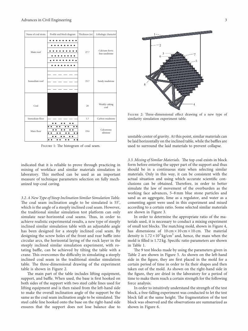
3.2. ANewType of Steep Inclination Similar Simulation Table.-e coal seam inclination angle to be simulated is 55°,which is the angle of a steeply inclined coal seam. However,the traditional similar simulation test platform can onlysimulate near-horizontal coal seams. -us, in order toachieve realistic experimental results, a new type of steeplyinclined similar simulation table with an adjustable anglehas been designed for a steeply inclined coal seam. Bydesigning the screw holes of the front and rear baffle intocircular arcs, the horizontal laying of the rock layer in thesteeply inclined similar simulation experiment, with ro-tating baffle, can be achieved by tilting the table with acrane. -is overcomes the difficulty in simulating a steeplyinclined coal seam in the traditional similar simulationtable. -e three-dimensional drawing of the experimenttable is shown in Figure 2.
-e main part of the table includes lifting equipment,support, and baffle. When used, the base is first hooked onboth sides of the support with two steel cable lines used forlifting equipment and is then raised from the left-hand sideto make the overall inclination angle of the support be thesame as the coal seam inclination angle to be simulated. -esteel cable line hooked onto the base on the right-hand sideensures that the support does not lose balance due to
unstable center of gravity. At this point, similar materials canbe laid horizontally on the inclined table, while the baffles areused to surround the laid materials to prevent collapse.
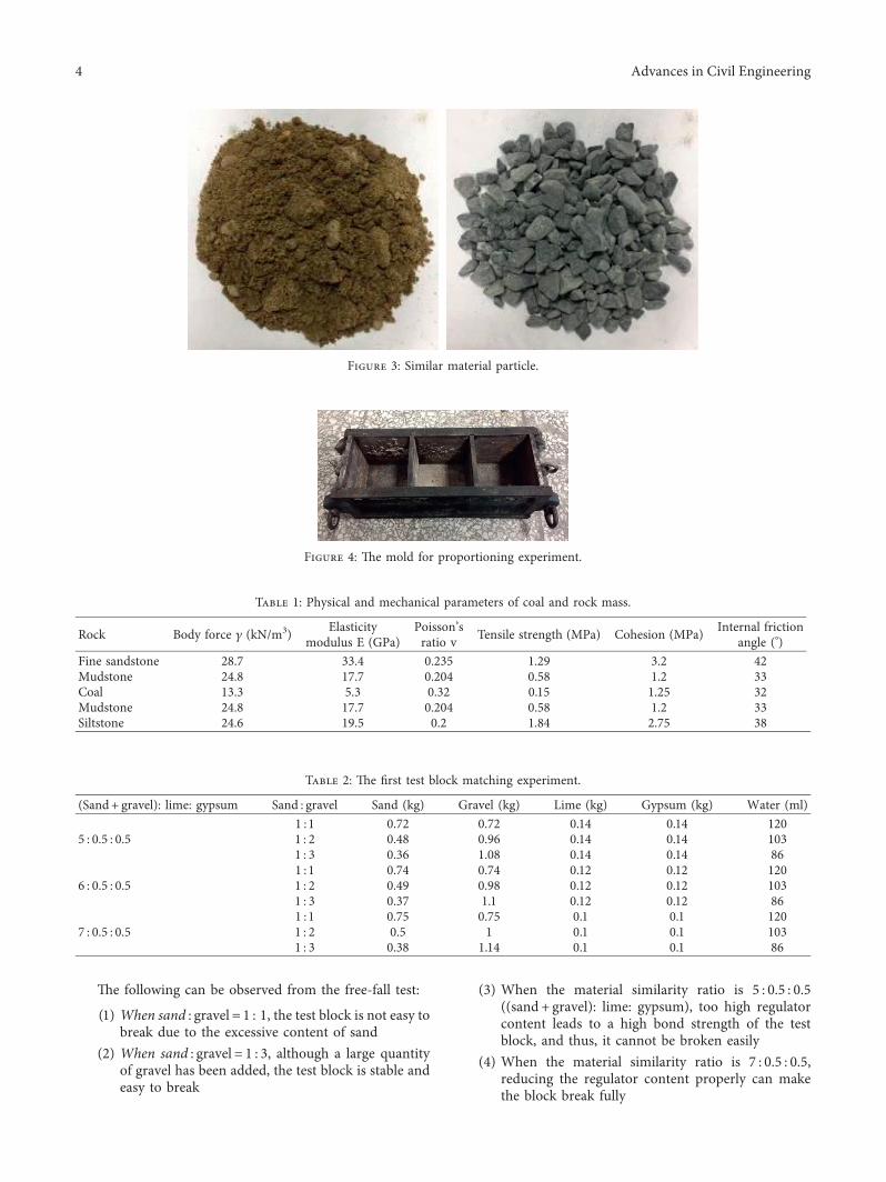
3.3. Mixing of SimilarMaterials. -e top coal exists in blockform before entering the upper part of the support and thusshould be in a continuous state when selecting similarmaterials. Only in this way, it can be consistent with theactual situation and using which accurate scientific con-clusions can be obtained. -erefore, in order to bettersimulate the law of movement of the overburden as theworking face advances, 5–8mm blue stone particles andsand as an aggregate, lime as a regulator, and water as acementing agent were used in this experiment and mixedaccording to a certain ratio. Some selected similar materialsare shown in Figure 3.
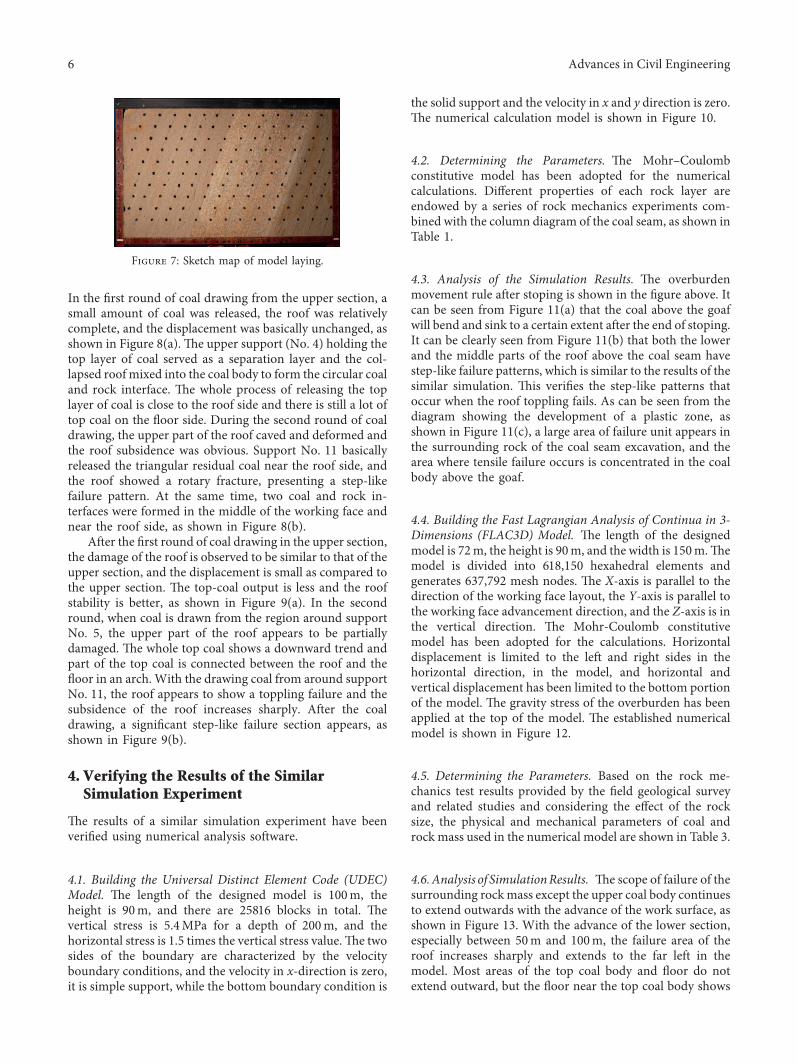
In order to determine the appropriate ratio of the ma-terials used, it is necessary to conduct a mixing experimentof small test blocks. -e matching mold, shown in Figure 4,has dimensions of 10 cm× 10 cm× 10 cm. -e materialdensity is 1.72×10³ kg/cm3 and, hence, the mass when themold is filled is 1.72 kg. Specific ratio parameters are shownin Table 1.
-e 9 test blocks made by using the parameters given inTable 2 are shown in Figure 5. As shown on the left-handside in the figure, they are first placed in the mold for acertain period of time in order to fix their shapes and thentaken out of the mold. As shown on the right-hand side inthe figure, they are dried in the laboratory for a period oftime to make them reach a certain strength for the followingforce analysis.
In order to intuitively understand the strength of the testblock, a free-falling experiment was conducted to let the testblock fall at the same height. -e fragmentation of the testblock was observed and the observations are summarized asshown in Figure 6.
1
2
3 7
5
4
8
6
Figure 2: -ree-dimensional effect drawing of a new type ofsimilarity simulation experiment table.
Name of coal strata
Main roof
Immediate roof
Coal
Immediate floor
Main floor
Profile and block diagram Thickness (m) Lithologic character
Calcium-ferricfine sandstone
Sandy mudstone
Weakly cakingcoal
Carbon mudstone
Calcareoussiltstone
27.7
25.7
20
1.7
19.6
Figure 1: -e histogram of coal seam.
Advances in Civil Engineering 3
-e following can be observed from the free-fall test:
(1) When sand : gravel� 1 : 1, the test block is not easy tobreak due to the excessive content of sand
(2) When sand : gravel� 1 : 3, although a large quantityof gravel has been added, the test block is stable andeasy to break
(3) When the material similarity ratio is 5 : 0.5 : 0.5((sand + gravel): lime: gypsum), too high regulatorcontent leads to a high bond strength of the testblock, and thus, it cannot be broken easily
(4) When the material similarity ratio is 7 : 0.5 : 0.5,reducing the regulator content properly can makethe block break fully
Figure 3: Similar material particle.
Figure 4: -e mold for proportioning experiment.
Table 1: Physical and mechanical parameters of coal and rock mass.
Rock Body force c (kN/m3) Elasticitymodulus E (GPa)
Poisson’sratio v Tensile strength (MPa) Cohesion (MPa) Internal friction
To sum up, in order to ensure that the similar simulationmaterials can reach a stable state and break sufficiently afterlaying, the similarity ratio chosen is (sand + gravel): lime:gypsum� 7 : 0.5 : 0.5, where sand: gravel� 1 : 3.
3.4. Experimental Design. According to the actual geologicaldata of the working face, it is known that the vertical height ofeach plate is 50m and is divided into two sections. Each sectionhas a height of 25m, out of which, the machine mining heightis 2.8m while the top-coal caving height is 22.2m. -e miningand caving ratio is close to 1 : 8. -e average length of theworking face is 17m, and the dip angle of the coal seam is 55°.
-e width of the table is 1.8m, and the overall height is1.4m. In order to present the complete mining condition ofthe two sections, the geometric similarity ratio is set asαL � 40 :1. According to the geometric similarity ratio, the
coal seam area has a thickness of 50 cm. Sand, lime, andgypsum were used for mixing on both sides of the roof andfloor as per the ratio mentioned above and the pressure fromthe overburden was simulated by placing heavy blocks. -eoverall effect after the experimental model is constructed isshown in Figure 7. In order to simulate the coal drawingprocess, 11 wooden boards with a thickness of 7 cm wereselected to simulate supports (numbered 1–11 from right toleft in Figure 7). Multiple rounds, intervals, and sequences ofcoal drawing from the floor of the coal seam to the roof havebeen adopted to discharge coal. -e upper section is minedfirst followed by the lower section.
3.5. Analysis of the Experimental Simulation. After thestrength of the experimental material reached its pre-determined value, excavation was carried out to draw coal.
Figure 5: Test block of different proportions.
1:3
1:2
1:1
7:0.5 :05 6:0.5 :05 5:0.5 :05
Figure 6: Free-falling experiment.
Advances in Civil Engineering 5
In the first round of coal drawing from the upper section, asmall amount of coal was released, the roof was relativelycomplete, and the displacement was basically unchanged, asshown in Figure 8(a). -e upper support (No. 4) holding thetop layer of coal served as a separation layer and the col-lapsed roof mixed into the coal body to form the circular coaland rock interface. -e whole process of releasing the toplayer of coal is close to the roof side and there is still a lot oftop coal on the floor side. During the second round of coaldrawing, the upper part of the roof caved and deformed andthe roof subsidence was obvious. Support No. 11 basicallyreleased the triangular residual coal near the roof side, andthe roof showed a rotary fracture, presenting a step-likefailure pattern. At the same time, two coal and rock in-terfaces were formed in the middle of the working face andnear the roof side, as shown in Figure 8(b).
After the first round of coal drawing in the upper section,the damage of the roof is observed to be similar to that of theupper section, and the displacement is small as compared tothe upper section. -e top-coal output is less and the roofstability is better, as shown in Figure 9(a). In the secondround, when coal is drawn from the region around supportNo. 5, the upper part of the roof appears to be partiallydamaged. -e whole top coal shows a downward trend andpart of the top coal is connected between the roof and thefloor in an arch. With the drawing coal from around supportNo. 11, the roof appears to show a toppling failure and thesubsidence of the roof increases sharply. After the coaldrawing, a significant step-like failure section appears, asshown in Figure 9(b).
4. Verifying the Results of the SimilarSimulation Experiment
-e results of a similar simulation experiment have beenverified using numerical analysis software.
4.1. Building the Universal Distinct Element Code (UDEC)Model. -e length of the designed model is 100m, theheight is 90m, and there are 25816 blocks in total. -evertical stress is 5.4MPa for a depth of 200m, and thehorizontal stress is 1.5 times the vertical stress value.-e twosides of the boundary are characterized by the velocityboundary conditions, and the velocity in x-direction is zero,it is simple support, while the bottom boundary condition is
the solid support and the velocity in x and y direction is zero.-e numerical calculation model is shown in Figure 10.
4.2. Determining the Parameters. -e Mohr–Coulombconstitutive model has been adopted for the numericalcalculations. Different properties of each rock layer areendowed by a series of rock mechanics experiments com-bined with the column diagram of the coal seam, as shown inTable 1.
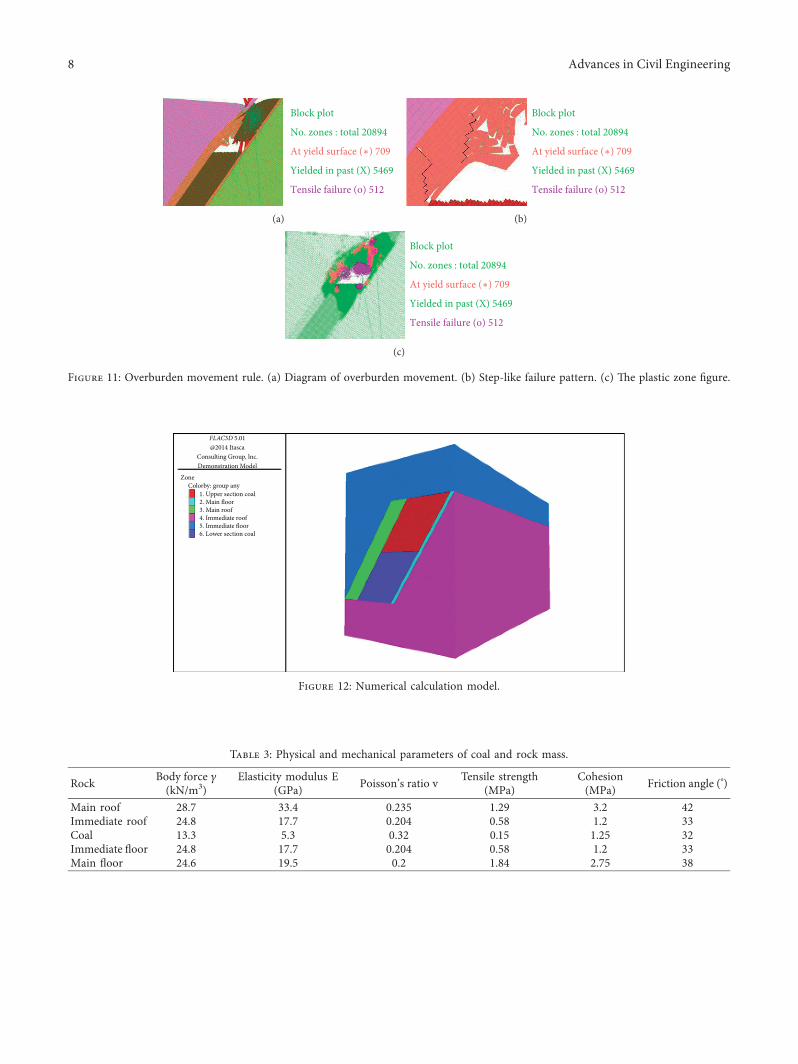
4.3. Analysis of the Simulation Results. -e overburdenmovement rule after stoping is shown in the figure above. Itcan be seen from Figure 11(a) that the coal above the goafwill bend and sink to a certain extent after the end of stoping.It can be clearly seen from Figure 11(b) that both the lowerand the middle parts of the roof above the coal seam havestep-like failure patterns, which is similar to the results of thesimilar simulation. -is verifies the step-like patterns thatoccur when the roof toppling fails. As can be seen from thediagram showing the development of a plastic zone, asshown in Figure 11(c), a large area of failure unit appears inthe surrounding rock of the coal seam excavation, and thearea where tensile failure occurs is concentrated in the coalbody above the goaf.
4.4. Building the Fast Lagrangian Analysis of Continua in 3-Dimensions (FLAC3D) Model. -e length of the designedmodel is 72m, the height is 90m, and the width is 150m.-emodel is divided into 618,150 hexahedral elements andgenerates 637,792 mesh nodes. -e X-axis is parallel to thedirection of the working face layout, the Y-axis is parallel tothe working face advancement direction, and the Z-axis is inthe vertical direction. -e Mohr-Coulomb constitutivemodel has been adopted for the calculations. Horizontaldisplacement is limited to the left and right sides in thehorizontal direction, in the model, and horizontal andvertical displacement has been limited to the bottom portionof the model. -e gravity stress of the overburden has beenapplied at the top of the model. -e established numericalmodel is shown in Figure 12.
4.5. Determining the Parameters. Based on the rock me-chanics test results provided by the field geological surveyand related studies and considering the effect of the rocksize, the physical and mechanical parameters of coal androck mass used in the numerical model are shown in Table 3.
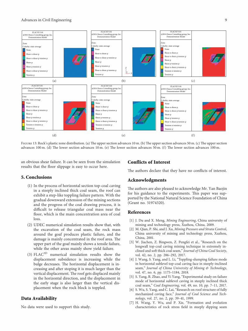
4.6.Analysis of SimulationResults. -e scope of failure of thesurrounding rockmass except the upper coal body continuesto extend outwards with the advance of the work surface, asshown in Figure 13. With the advance of the lower section,especially between 50m and 100m, the failure area of theroof increases sharply and extends to the far left in themodel. Most areas of the top coal body and floor do notextend outward, but the floor near the top coal body shows
Figure 7: Sketch map of model laying.
6 Advances in Civil Engineering
(a) (b)
Figure 9: Lower section coal drawing process. (a) Before lower section coal drawing. (b) After lower section coal drawing.
Figure 11: Overburden movement rule. (a) Diagram of overburden movement. (b) Step-like failure pattern. (c) -e plastic zone figure.
8 Advances in Civil Engineering
an obvious shear failure. It can be seen from the simulationresults that the floor slippage is easy to occur here.
5. Conclusions
(1) In the process of horizontal section top-coal cavingin a steeply inclined thick coal seam, the roof canexhibit a step-like toppling failure pattern. With thegradual downward extension of the mining sectionsand the progress of the coal drawing process, it isdifficult to release triangular coal mass near thefloor, which is the main concentration area of coalloss.
(2) UDEC numerical simulation results show that, withthe excavation of the coal seam, the rock massaround the goaf produces plastic failure, and thedamage is mainly concentrated in the roof area. -eupper part of the goaf mainly shows a tensile failure,while the other areas mainly show yield failure.
(3) FLAC3D numerical simulation results show thedisplacement subsidence is increasing while thebulge decreases. -e horizontal displacement is in-creasing and after stoping it is much larger than thevertical displacement. -e roof gets displaced mainlyin the horizontal direction, and the displacement inthe early stage is also larger than the vertical dis-placement when the rock block is toppled.
Data Availability
No data were used to support this study.
Conflicts of Interest
-e authors declare that they have no conflicts of interest.
Acknowledgments
-e authors are also pleased to acknowledge Mr. Yan Baojinfor his guidance to the experiments. -is paper was sup-ported by the National Natural Science Foundation of China(Grant no. 51974320).
References
[1] J. Du and X. Meng, Mining Engineering, China university ofmining and technology press, Xuzhou, China, 2009.
[2] M. Qian, P. Shi, and J. Xu,Mining Pressure and Strata Control,China university of mining and technology press, Xuzhou,China, 2001.
[3] W. Jiachen, Z. Bingwen, Z. Pengfei et al., “Research on thelongwall top-coal caving mining technique in extremely in-clined and soft thick coal seam,” Journal of China Coal Society,vol. 42, no. 2, pp. 286–292, 2017.
[4] J. Wang, S. Yang, and L. Li, “Toppling-slumping failure modein horizontal sublevel top-coal caving face in steeply-inclinedseam,” Journal of China University of Mining & Technology,vol. 47, no. 6, pp. 1175–1184, 2018.
[5] S. Yang, B. Zhao, and Yi Yang, “Experimental study on failuremode of horizontal sublevel caving in steeply inclined thickcoal seam,” Coal Engineering, vol. 49, no. 10, pp. 7–11, 2017.
[6] S. Wu, S. Yang, and C. Lai, “Research on roof structure of fullymechanized caving face,” Journal of Coal Science and Tech-nology, vol. 27, no. 2, pp. 39–41, 1999.
[7] H. Wang, Y. Wu, and P. Xie, “Formation and evolutioncharacteristics of rock stress field in steeply dipping seam
FLAC3D 5.01@2014 Itasca Consulting group, lnc.
Demonstration Model
ZoneColorby: state-average
None
Shear-n shear-p
Shear-n shear-p tension-p
Shear-p
Shear-p tension-p
Shear-n shear-p tension-p
Tension-p
(a)
FLAC3D 5.01@2014 Itasca Consulting group, lnc.
Demonstration Model
ZoneColorby: state-average
None
Shear-n shear-p
Shear-n shear-p tension-p
Shear-p
Shear-p tension-p
Shear-n shear-p tension-p
Tension-p
Z
XY
(b)
FLAC3D 5.01@2014 Itasca Consulting group, lnc.
Demonstration Model
ZoneColorby: state-average
None
Shear-n shear-p
Shear-n shear-p tension-p
Shear-p
Shear-p tension-p
Shear-n shear-p tension-p
Tension-p
Tension-n tension-p
(c)FLAC3D 5.01
@2014 Itasca Consulting group, lnc.Demonstration Model
mining,” Journal of Lliaoning Technical University (NaturalScience), vol. 32, no. 8, pp. 1022–1026, 2013.
[8] G. Yin, D. Wang, and W. Zhang, “Mechanical model andapplication of overburden deformation in deep mining ofsteeply inclined coal seam,” Journal of Chongqing University(Natural Science Edition), vol. 29, no. 2, pp. 79–82, 2006.
[9] Y. Zhang, J. Cheng, X. Wang et al., “-in plate model analysison roof break of up-dip or down-dip mining stope,” Journal ofMining & Safety Engineering, vol. 27, no. 4, pp. 487–493, 2010.
[10] N. Zhou, Q. Zhang, B. An, and S. Nie, “Strata behavior belowthe gobs of close upper seams [J],” China Coal, vol. 37, no. 2,pp. 48–51+96, 2011.
[11] H. Hu, “Failure characteristics of overburden rock in hori-zontal sublevel fully mechanized caving in steeply inclinedextra-thick coal seam,” Inner Mongolia Coal Economy, no. 11,pp. 104–119, 2015.
[12] Q. Zhang, S. Li, and Y. Li, New Method, New Technology andEngineering Application of Underground Engineering ModelTest, Science Press, Beijing, China, 2012.
[13] X. Meng, Y. Zhang, L. Chaohui, Z. Li, and Y. Guo, “Study oftechnique simulating test on fully mechanized top-coal cavingwork face in greater inclined and thick coal seams,” ChinaMining Magazine, vol. 18, no. 3, pp. 72–76, 2009.


![Case Report of a Tibial Plateau Fracture Extending Through the … · describes tibia plateau fracture patterns and serves to guide operative treatment [5]. This fracture pattern](https://static.documents.pub/doc/80x56/5d1e74de88c99335368d6437/case-report-of-a-tibial-plateau-fracture-extending-through-the-describes-tibia.jpg)


