1 of 12 MATLAB-Simulink Model of a Stand-Alone Induction Generator 1 Gheorghe Scutaru, 2 Constantin Apostoaia 1 “Transilvania” University of Brasov - Romania, Faculty of Electrical Engineering and Computer Science, Department of Electrotechnics, 500039 Brasov - Romania, Tel., Fax: 00 40-268-474718, E-mail: [email protected]2 Member, IEEE, Purdue University Calumet-USA, Department of Electrical and Computer Engineering, Tel. 001 219-989-2472, Fax: 001 219-989-2898, E-mail: [email protected]Abstract ─ This paper presents modeling, simulation and optimization of an induction generator. The induction machine is represented with a saturation adaptive induction machine dynamic model having state variables expressed in terms of fluxes and reactances. Transients of machine self-excitation under a three-phase load application are simulated using a Simulink block diagram. The magnetization reactance and generated frequency are computed by constrained minimization method for generator operating mode by using the function fmincon from Matlab Optimization Toolbox. Index Terms ─ Induction generator, state-space model, constrained minimization method. I. INTRODUCTION There is no doubt that so called the problem of “exhaustion of planet classical energy resources” is now very well known. Some practical realizations and numerous scientific papers insisted on the key solution of increasing the efficiency of so called renewable energies of biomass, wind, seas and oceans, earth heat, solar energy, small rivers, etc. Wind turbine based power generation systems are the fastest growing source of renewable energy. During a recent year, the market for small wind systems in the U.S., those with less than 100kW of generating capacity, grew more than 35%. American Wind Energy Association (AWEA) expects continued growth in this market [1]. In the field of electric generators driven by wind turbines the research and development of new control techniques can increase the system efficiency based on variable speed operation mode. An alternative for operation of energetic groups at variable speed may be the use of the induction generator. In numerous studies the induction machines are frequently modeled by means of the space phasors theory applied on the d – q axis models [2] – [8]. Self excited induction generators are today frequently considered as the most economical solution for powering costumers isolated from the utility grid. At the present time self excited induction generator technology is replacing conventional generators based on permanent magnet technology because of their low unit cost, robustness, ease of operation and maintenance. Various dynamic operation regimes of the stand-alone induction generator (i.e., the self excitation process) require advanced new models. Main flux saturation
Transcript
1 of 8
MATLAB-Simulink Model of a Stand-Alone Induction Generator
1Gheorghe Scutaru, 2Constantin Apostoaia 1“Transilvania” University of Brasov - Romania, Faculty of Electrical Engineering and Computer Science,
Department of Electrotechnics, 500039 Brasov - Romania, Tel., Fax: 00 40-268-474718, E-mail: [email protected]
2 Member, IEEE, Purdue University Calumet-USA, Department of Electrical and Computer Engineering, Tel. 001 219-989-2472, Fax: 001 219-989-2898, E-mail: [email protected]
Abstract ─ This paper presents modeling, simulation and optimization of an induction generator. The induction machine is represented with a saturation adaptive induction machine dynamic model having state variables expressed in terms of fluxes and reactances. Transients of machine self-excitation under a three-phase load application are simulated using a Simulink block diagram. The magnetization reactance and generated frequency are computed by constrained minimization method for generator operating mode by using the function fmincon from Matlab Optimization Toolbox.
Index Terms ─ Induction generator, state-space model, constrained minimization method.
I. INTRODUCTION
There is no doubt that so called the problem of “exhaustion of planet classical energy resources” is now very well known. Some practical realizations and numerous scientific papers insisted on the key solution of increasing the efficiency of so called renewable energies of biomass, wind, seas and oceans, earth heat, solar energy, small rivers, etc. Wind turbine based power generation systems are the fastest growing source of renewable energy. During a recent year, the market for small wind systems in the U.S., those with less than 100kW of generating capacity, grew more than 35%. American Wind Energy Association (AWEA) expects continued growth in this market [1].
In the field of electric generators driven by wind turbines the research and development of new control techniques can increase the system efficiency based on variable speed operation mode. An alternative for operation of energetic groups at variable speed may be the use of the induction generator. In numerous studies the induction machines are frequently modeled by means of the space phasors theory applied on the d – q axis models [2] – [8].
Self excited induction generators are today frequently considered as the most economical solution for powering costumers isolated from the utility grid. At the present time self excited induction generator
technology is replacing conventional generators based on permanent magnet technology because of their low unit cost, robustness, ease of operation and maintenance. Various dynamic operation regimes of the stand-alone induction generator (i.e., the self excitation process) require advanced new models. Main flux saturation adaptive models have been a subject of great interest in recent years [3], [7], [9] – [13].
In many scientific papers models of the induction machine based on parameters identification algorithms and estimation techniques were reported [13], [14].
Based on adaptive models to parameters variation, different studies of the transients of the induction machine were performed [3], [4], [7], [11], [15] – [18].
The analysis of the steady state regime of the induction generator and the optimization of the machine design were the subject of some studies [19] – [22].
The progress in power electronics reduces the cost of implementing induction generator control, a past disadvantage associated with the use of an induction machine. Secondarily, the electronic power converters can ease integration of wind turbines working in groups.
In the last two or three decades, we have seen extensive research and development efforts for variable-frequency, variable-speed ac machine drive technology. In most cases, new applications use ac drives replacing progressively variable-speed dc drives. Various strategies for induction generator control of power, voltage, frequency, or current, were proposed and some DSP-based systems have been implemented, [4], [6], [7], [11], [12], [18], [23] – [29].
Since the induction generator operating frequency and output voltage are determined by the speed of the generator, the load, and the value of the excitation capacitor, fixed capacitor values can result in unstable power output under changing load conditions. An isolated induction generator can operate in a stable
2 of 8
manner with an appropriate control strategy and the use of solid state power switching devices to regulate the amount of self excitation.
Among all types of ac machines (induction machines, synchronous machines, and variable reluctance machines), the induction machine, particularly the cage type, is very economical, reliable, and is available in the ranges of fractional horse power to multi-megawatt capacity. Low-power machines are available in single-phase, but three-phase machines are used most often in variable-speed drives.
We are interested in this paper to study the generator operating mode of the three-phase induction machine. We perform modeling and simulation studies of a self excited induction generator, the most economical solution for powering costumers isolated from the utility grid [1].
Finally, the aim of this paper is to optimize the design of the induction generator and to describe the simulation results in Matlab-Simulink environment.
II. STAND-ALONE INDUCTION GENERATOR MODEL
A. Induction machine dynamic model
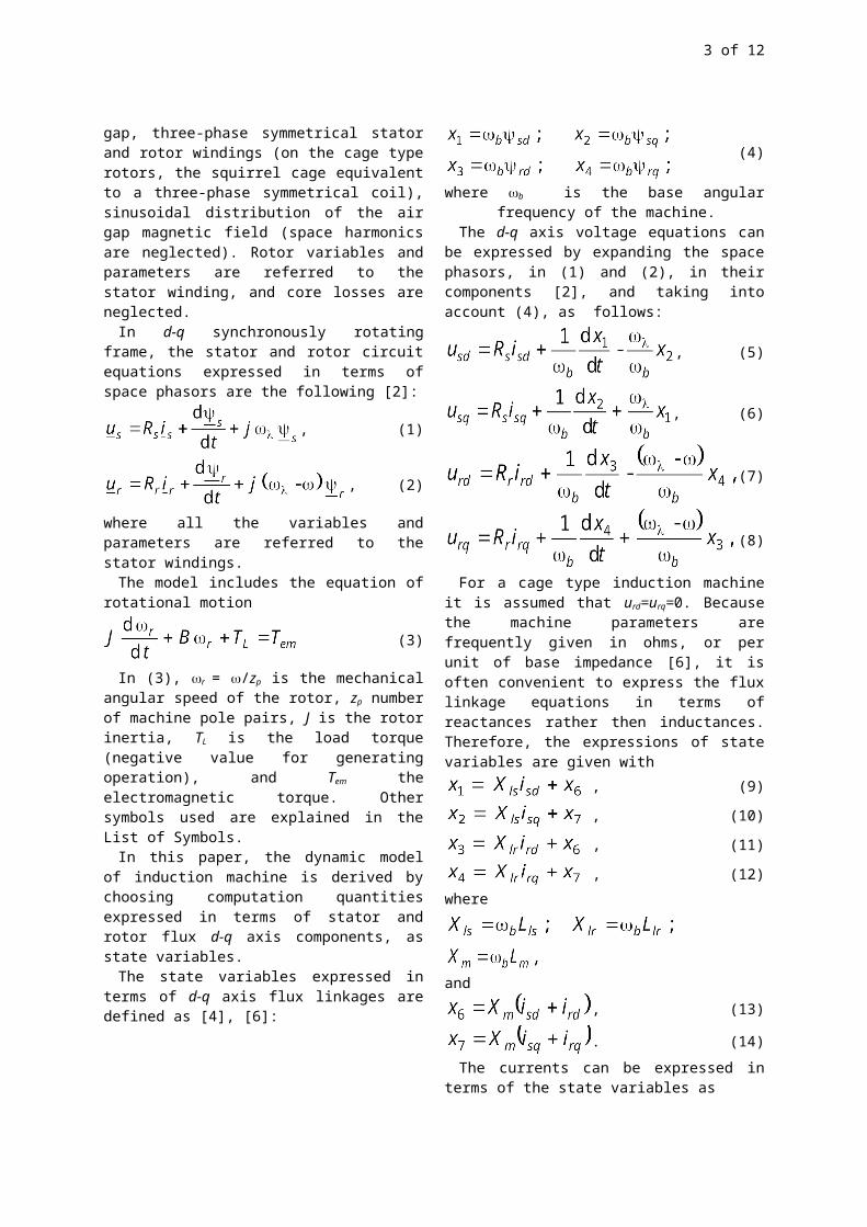
The dynamic d-q model of the induction machine derived in this paper is based on some assumptions: cylinder type rotor, constant air gap, three-phase symmetrical stator and rotor windings (on the cage type rotors, the squirrel cage equivalent to a three-phase symmetrical coil), sinusoidal distribution of the air gap magnetic field (space harmonics are neglected). Rotor variables and parameters are referred to the stator winding, and core losses are neglected.
In d-q synchronously rotating frame, the stator and rotor circuit equations expressed in terms of space phasors are the following [2]:
, (1)
, (2)
where all the variables and parameters are referred to the stator windings.
The model includes the equation of rotational motion
(3)
In (3), r = /zp is the mechanical angular speed of the rotor, zp number of machine pole pairs, J is the rotor inertia, TL is the load torque (negative value for
generating operation), and Tem the electromagnetic torque. Other symbols used are explained in the List of Symbols.
In this paper, the dynamic model of induction machine is derived by choosing computation quantities expressed in terms of stator and rotor flux d-q axis components, as state variables.
The state variables expressed in terms of d-q axis flux linkages are defined as [4], [6]:
(4)
where b is the base angular frequency of the machine.
The d-q axis voltage equations can be expressed by expanding the space phasors, in (1) and (2), in their components [2], and taking into account (4), as follows:
, (5)
, (6)
(7)
(8)
For a cage type induction machine it is assumed that urd=urq=0. Because the machine parameters are frequently given in ohms, or per unit of base impedance [6], it is often convenient to express the flux linkage equations in terms of reactances rather then inductances. Therefore, the expressions of state variables are given with
, (9)
, (10)
, (11)
, (12)where
and
, (13)
. (14)
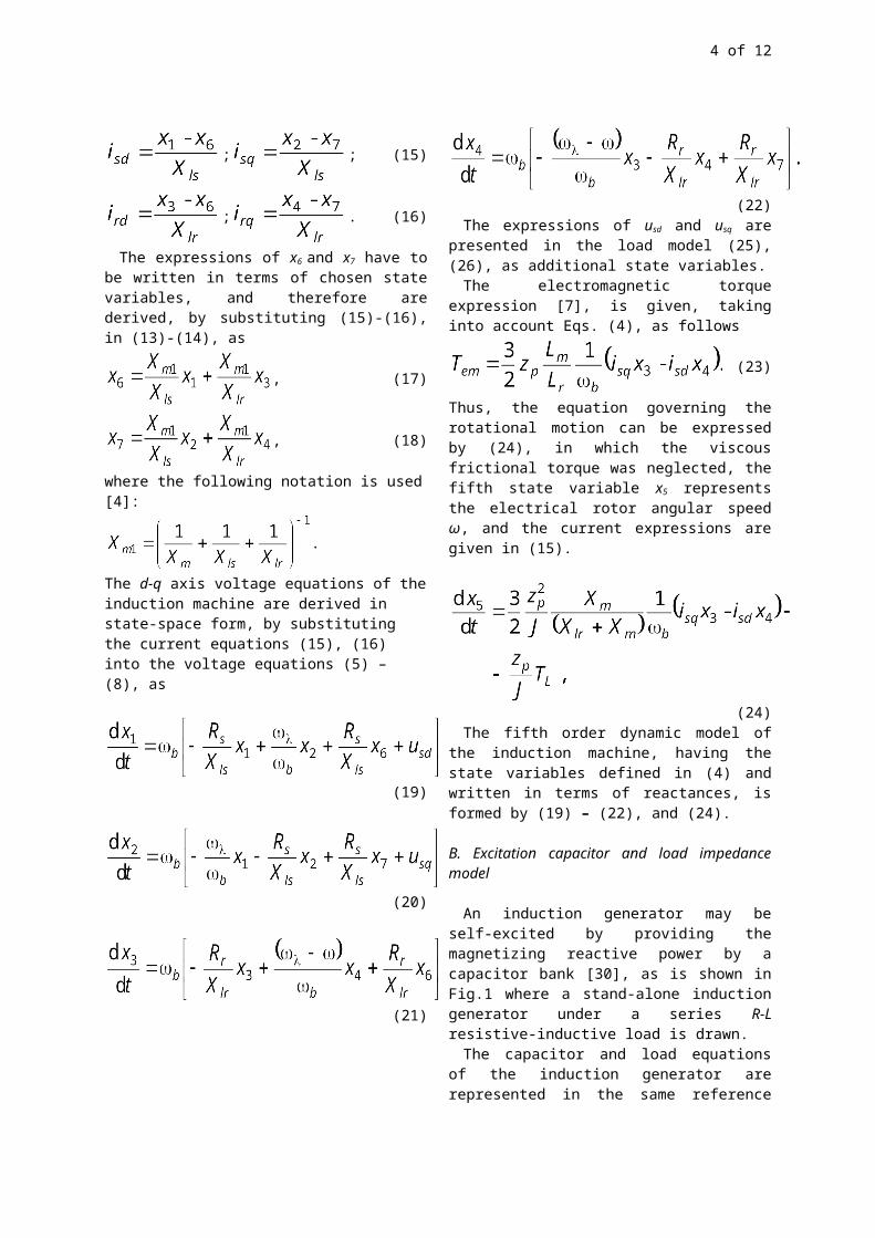
The currents can be expressed in terms of the state variables as
; ; (15)
; . (16)
3 of 8
The expressions of x6 and x7 have to be written in terms of chosen state variables, and therefore are derived, by substituting (15)-(16), in (13)-(14), as
, (17)
, (18)
where the following notation is used [4]:
.
The d-q axis voltage equations of the induction machine are derived in state-space form, by substituting the current equations (15), (16) into the voltage equations (5) – (8), as
(19)
(20)
(21)
(22)
The expressions of usd and usq are presented in the load model (25), (26), as additional state variables.
The electromagnetic torque expression [7], is given, taking into account Eqs. (4), as follows
(23)
Thus, the equation governing the rotational motion can be expressed by (24), in which the viscous frictional torque was neglected, the fifth state variable x5 represents the electrical rotor angular speed ω, and the current expressions are given in (15).
(24)The fifth order dynamic model of the induction
machine, having the state variables defined in (4) and written in terms of reactances, is formed by (19) – (22), and (24).
B. Excitation capacitor and load impedance model
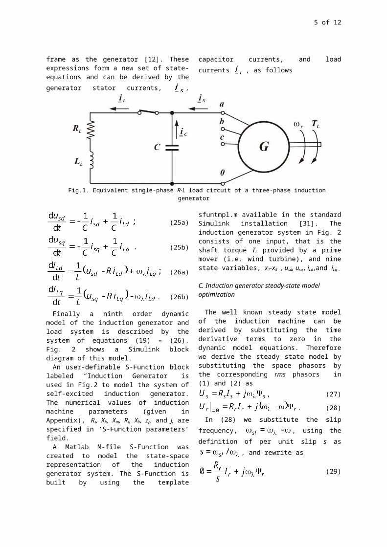
An induction generator may be self-excited by providing the magnetizing reactive power by a capacitor bank [30], as is shown in Fig.1 where a stand-alone induction generator under a series R-L resistive-inductive load is drawn.
The capacitor and load equations of the induction generator are represented in the same reference frame as the generator [12]. These expressions form a new set of state-equations and can be derived by the generator stator currents, , capacitor currents, and
load currents , as follows
Fig.1. Equivalent single-phase R-L load circuit of a three-phase induction generator
(25a) (25b)
4 of 8
(26a)
. (26b)
Finally a ninth order dynamic model of the induction generator and load system is described by the system of equations (19) – (26). Fig. 2 shows a Simulink block diagram of this model.
An user-definable S-Function block labeled “Induction Generator” is used in Fig.2 to model the system of self-excited induction generator. The numerical values of induction machine parameters (given in Appendix), Rs, Xls, Xm, Rr, Xlr, zp, and J, are specified in ‘S-Function parameters’ field.
A Matlab M-file S-Function was created to model the state-space representation of the induction generator system. The S-Function is built by using the template sfuntmpl.m available in the standard Simulink installation [31]. The induction generator system in Fig. 2 consists of one input, that is the shaft torque TL provided by a prime mover (i.e. wind turbine), and nine state variables, x1-x5 , usd, usq , iLd
,and iLq .
C. Induction generator steady-state model optimization
The well known steady state model of the induction machine can be derived by substituting the time derivative terms to zero in the dynamic model equations. Therefore we derive the steady state model by substituting the space phasors by the corresponding rms phasors in (1) and (2) as
, (27)
. (28)
In (28) we substitute the slip frequency, , using the definition of per unit slip s
as , and rewrite as
(29)
The model expressed by (27) and (29) satisfy the well known steady state equivalent circuit of an induction machine, if the parameter Rm of equivalent resistance for core loss is neglected.
We consider a three-phase self-excited induction generator to which a prime mover is coupled
mechanically and operating in parallel with a three-phase capacitor bank capable of supplying the necessary magnetizing current. The generator operating frequency and voltage are determined by the speed of the generator, its load, and the capacitor rating. As for the dc shunt generator, for the induction generator to self-excite, its rotor must have sufficient remnant flux. Since the machine is driven at variable speed, and thus operates at a variable stator frequency f = ω /2π, it is convenient to use in analysis the machine equivalent circuit where all the parameters are referred to rated frequency, assuming that all inductive reactances are proportional to the frequency. The per-phase steady-state equivalent circuit of a self-excited induction generator supplying a balanced R-L load is shown in Fig. 3.
Defining the base impedance in ohms, , all resistances and reactances of the
equivalent circuit in Fig. 3 are expressed in per units
(e.g. stator resistance, ), and Vg,
Vo are the air gap and output voltages respectively.The symbols F and u, in Fig. 3, have the following
significance:F, is the ratio of the generated frequency to base
frequency, F=f / fb;u, is the ratio of the actual rotor speed to the
synchronous speed corresponding to base frequency, u = r /ω.
If n is the actual rotor speed in rpm, the slip s can be expressed as .
For the machine to operate, Xm must have a value in the saturated region of the magnetization characteristic. That is the bound , and X0 is the (p.u.) unsaturated magnetizing reactance.
Because the value of slip is negative for generator action this gives the bound , on the range of generated frequency.
D. Analysis by Constrained Minimization Method
The steady state analysis of three phase self-excited induction generator can be formulated as a numerical multidimensional optimization problem, where no detailed derivation of analytical equations is needed [19]. An efficient method, using several-variable constrained minimization, solves the problem directly. This method returns the parameters of interest by minimizing a cost function.
5 of 8
Fig.2. Simulink block diagram of the dynamic model of induction generator system
Fig. 3. Per unit steady-state equivalent circuit of self-excited induction generator under R-L load.
In Fig. 3 all the circuit parameters are assumed to be constant and are independent of saturation except the magnetizing reactance Xm. Core loss and effect of harmonics in the machine are neglected.
Under steady state conditions, KVL applied in Fig.3 gives .
The total impedance Ztotal is computed considering the following impedance definitions
; ;
;
; ;
;
; ;
Since , it implies that in equation
, or
As a consequence, the total impedance will be considered as an objective function and the equations Re(Ztotal)=0 and Im(Ztotal)=0 can be solved simultaneously for two unknowns[19].
In this paper the constrained minimization method is applied to find simultaneously the values of the frequency F, and of the magnetization reactance Xm by minimizing the total impedance, Ztotal. Gradient optimizers, such as those built in the Optimization Toolbox from Matlab, can be used for this purpose. In our analysis, the function fmincon available in Matlab 6.x versions is used.
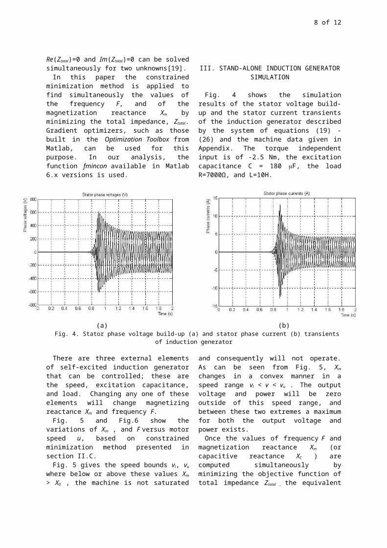
III. STAND-ALONE INDUCTION GENERATOR SIMULATION
Fig. 4 shows the simulation results of the stator voltage build-up and the stator current transients of the induction generator described by the system of
6 of 8
equations (19) - (26) and the machine data given in Appendix. The torque independent input is of -2.5
Nm, the excitation capacitance C = 180 F, the load R=7000Ω, and L=10H.
(a) (b)Fig. 4. Stator phase voltage build-up (a) and stator phase current (b) transients of induction generator
There are three external elements of self-excited induction generator that can be controlled; these are the speed, excitation capacitance, and load. Changing any one of these elements will change magnetizing reactance Xm and frequency F.
Fig. 5 and Fig.6 show the variations of Xm , and F versus motor speed u, based on constrained minimization method presented in section II.C.
Fig. 5 gives the speed bounds vl, vu where below or above these values Xm > X0 , the machine is not saturated and consequently will not operate. As can be seen from Fig. 5, Xm changes in a convex manner in a speed range vl < v < vu . The output voltage and power will be zero outside of this speed range, and between
these two extremes a maximum for both the output voltage and power exists.
Once the values of frequency F and magnetization reactance Xm (or capacitive reactance XC ) are computed simultaneously by minimizing the objective function of total impedance Ztotal , the equivalent circuit in Fig. 3 is to be solved to determine the generator performance [21]. This can be obtained from the magnetization characteristic of the machine. Typically the function m =f(im) has the general shape shown in Fig. 7 which was obtained by cubic spline experimental data interpolation considering the induction machine in Appendix.
Fig.5. Variation of Xm (p.u) .) versus speed Fig. 6. Variation of frequency (p.u.) F versus speed
7 of 8
Fig.7. The magnetization curve m versus im Fig. 8. Magnetization inductance Lm versus im
IV. CONCLUSION
In this paper, two approaches were used in order to achieve the proposed goal of the study, that is, to add a contribution to the design optimization of the induction generator. On one hand, a flexible dynamic model is designed for transients simulation purposes. On the other hand, a numerical constraint minimization method is applied with the aim of machine’s parameter design optimization. For the dynamic model, the contribution of this study is the creation of the induction generator subsystem in the Simulink block diagram (Fig. 2). This subsystem is based on an original Matlab source code written to build an m.file S-Function which models the state space model of the induction generator. The transients of the stator phase voltages build-up and stator phase currents were simulated and presented in Fig. 4. The subsystem block of the induction generator is flexible and easy to be inserted in future control systems of the induction machine.
In order to determine optimum values of some parameters an objective function, based on the steady state model shown in Fig. 3, is minimized. In this study, a new Matlab script file was created by using the function fmincon available in the Optimization Toolbox of Matlab 6.x versions.
The results of this study will be used in future research to design a prototype model of an isolated induction generator, to design a vector control system of a stand-alone induction generator system, and to model and simulate the overall energy conversion system containing a cluster of machines “turbine-induction generator-controller-grid”.
APPENDIX
A. List of Symbols
: subscripts, denoting stator and rotor quantities: transient voltages, currents, and fluxes
space phasors (e.g., )
: steady-state voltage, current, and flux
: electrical (mechanical) rotor
angular speed, d-q rotating reference frame speed, base frequency of the machine, slip frequency
: stator, rotor, ohmic resistances
: rotor inertia, coefficient of viscous friction, number of machine pole pairs
[1] American Wind Energy Association website: www.awea.org.
[2] A.Kelemen, Maria Imecs, “Vector Control of AC Drives”, Vol. 1, pp.22, OMIKK Publisher, Budapest, 1992.
[3] E. Levi, “A Unified Approach to Main Flux Saturation Modelling in D-Q Axis Models of Induction Machines”, IEEE Transactions on Energy Conversion, Vol. 10, No. 3, September 1995, pp. 455-461.
[4] B.K. Bose, „Modern power electronics and ac drives”, Prentice Hall, 2002.
[5] I., Boldea, “The Parameters of Electric Machines”, (Romanian), Romanian Academy Publishing Company, Bucharest, 1991.
[6] P.C. Krause, O. Wasynczuk, S.D. Sudhoff, „Analysis of Electric Machinery and Drive Systems”, J. Wiley&Sons Inc., 2002.
[7] C. Apostoaia, „Research on the Control of Asynchronous Machine Based on the Field Orientation Principle”, Doctoral Thesis, Brasov, Romania, 1998.
[8] Olorunfemi Ojo, „Minimum airgap flux linkage requirement foe self-excitation in stand-alone induction generators”, IEEE Trans. on Energy Conversion, Vol. 10, No. 3, September 1995, pp.484-492.
[9] Gh., Scutaru, C., Apostoaia, “Magnetization Characteristics on Three-Phase Asynchronous Motors, in Proc. OPTIM’91, “Transilvania” University of Brasov, Romania, October 10-12, 1991, vol. I, pp.79-84.
[10] E. Levi, “Impact of Cross-Saturation on Accuracy of Saturated Induction Machine Models”, IEEE Transactions on Energy Conversion, Vol. 12, No. 3, September 1997, pp. 211-216.
[11] E., Levi, V., Vuckovic, “Field-Oriented Control of Induction Machines in the Presence of Magnetic Saturation”, in Electric Machines and Power Systems, 1989, 16, p.p. 133-147.
[12] Y.W. Liao, E. Levi, “Modelling and simulation of a stand-alone induction generator with rotor flux oriented control”, Electric Power Systems Research, 46, 1998, pp. 141-152.
[13] E.Levi, “Online Identification of the Mutual Inductance for Vector Controlled Induction Motor Drives”, IEEE Transactions on Energy Conversion, Vol. 18, No. 2, June 2003, pp. 299-305.
[14] H.A. Toliyat, E. Levi, M. Raina, “A Review of RFO Induction Motor Parameter Estimation Techniques”, IEEE Transactions on Energy Conversion, Vol. 18, No. 2, June 2003, pp. 271-283.
[15] Li Wang, Jian-Yi Su, „Dynamic performances of an isolated self-excited induction generator under various loading conditions”, IEEE Trans. on Energy Conversion, Vol. 14, No. 1, March 1999, pp.93-100.
[16] Li Wang, R-Y. Deng, “Transient Performance of an Isolated Induction Generator Under Unbalanced Excitation Capacitors”, IEEE Transactions on Energy Conversion, Vol. 14, No. 4, December 1999, pp. 887-893.
[17] C.S. Demoulias, P.S. Dokopoulos, “Transient Behavior and Self-Excitation of Wind-Driven Induction Generator after its Disconnection from the Power Grid”, IEEE Transactions on Energy Conversion, Vol. 5, No. 2, June 1990, pp. 272-278.
[18] E. Suarez, G. Bortolotto, “Voltage-Frequency Control of a Self Excited Induction Generator”, IEEE Transactions on Energy Conversion, Vol. 14, No. 3, September 1999, pp. 394-401.
[19] A.I. Alolah and M.A. Alkanhal, „Optimization-based steady state analysis of three phase self-excited induction generator”, IEEE Trans. on Energy Conversion, Vol. 15, No. 1, March 2000.
[20] N.H. Malik and S.E. Haque, “Steady state analysis and performance of an isolated self-excited induction generator”, IEEE Trans. on Energy Conversion, Vol. EC-1, No. 3, September 1986.
[21] A.Kh. Al Jabri and A.I. Alolah, „Limits on the performance of the three-phase self-excited induction generators”, IEEE Trans. on Energy Conversion, Vol. 5, No. 2, June 1990.
[22] T.F. Chan, “Analysis of Self-Excited Induction Generators Using an Iterative Method”, IEEE Transactions on Energy Conversion, Vol. 10, No. 3, September 1995, pp. 502-507.
[23] Gh., Scutaru, C., Apostoaia, “Study of Control Channels Interaction within a Field Oriented System of an Induction Machine”, in Scientific Bulletin of “Transilvania” University of Brasov, Romania, 1994, vol. 1 (36)-New Series, Series A, pp. 133-140.
[24] I.T. Wallace, D.W. Novotny, R.D. Lorenz, D.M. Divan, “Verification of Enhanced Dynamic Torque per Ampere Capability in Saturated Induction Machines”, IEEE Transactions on Industry Applications, Vol. 30, No. 5, September/October 1994, pp. 1193-1201.
[25] Yang Ye, M. Kazerani, V.H. Quintana, “Modeling, Control, and Implementation of Three-Phase PWM Converters”, IEEE Transactions on Power Electronics, Vol. 18, No. 3, May 2003, pp. 857-864.
[26] A. Tapia, J.X. Ostolaza, J.R. Saenz, “Modeling and Control of a Wind Turbine Driven Doubly Fed Induction Generator”, IEEE Transactions on Energy Conversion, Vol. 18, No. 2, June 2003, pp. 194-204.
[27] W. Hofmann, A. Thieme, “Control of a Double-Fed Induction Generator for Wind-Power Plants”, PCIM’98, May 1998 Nurnberg, Power Quality Proceedings pp. 275-282.
[28] S. Corsi, M. Pozzi, G. Tagliabue, “A new Real-Time Digital Simulator of the Turbine-Alternator-Grid System (STAR) for Control Apparatus Closed0Loop Tests”, IEEE Transactions on Energy Conversion, Vol. 13, No. 3, September 1998, pp. 282-291.
[29] R. Datta, V.T. Ranganathan, “A Method of Tracking the Peak Power Points for a Variable Speed Wind Energy Conversion System”, IEEE Transactions on Energy Conversion, Vol. 18, No. 1, March 2003, pp. 163-168.