57
Dipl.Ing.Gartner Corrugated Web Beam documentation, Page 1 SINBEAM (CORRUGATED WEB BEAM)
| Date post: | 23-May-2018 |
| Category: |
Documents |
| Upload: | duongnguyet |
| View: | 225 times |
| Download: | 1 times |

Dipl.Ing.Gartner Corrugated Web Beam documentation, Page 1
SINBEAM
(CORRUGATED WEB BEAM)

Dipl.Ing.Gartner Corrugated Web Beam documentation, Page 2
TECHNICAL DOCUMENTATION
Zeman & Co Gesellschaft mbH
A-1120 Vienna, Austria, Schönbrunner Straße 213-215
Phone: (+43) 01 / 814 14-0, Fax: 01 / 812 27 13
http://www.zeman-steel.com, e-mail: [email protected]
Table of Contents:
A. GENERAL
1. General description and application 4
2. Basis for calculation 6
3. Product range and designation 7
4. Material 11
5. Corrosion protection 11
6. Tolerances 11
7. Quality monitoring 12
B. TECHNICAL
8. Load bearing capacity of webs and flanges 13
9. Dimensioning of beams 23
10. Dimensioning of columns 25
11. Verification of local load introduction 25
12. Section properties for corrugated web beams 26
13. Standards and Expert Opinions 27
Dipl.Ing.Gartner Corrugated Web Beam documentation, Page 3
C. TABLES
14. Section properties 29
15. Transverse load bearing capacity 37
16. Concentrated load introduction 39
17. Flange load bearing capacity 41
D. ANNEXURES
18. Practical examples 43
Version: December 2012
Dipl.Ing.Gartner Corrugated Web Beam documentation, Page 4
A. GENERAL SECTION
1. General description and application
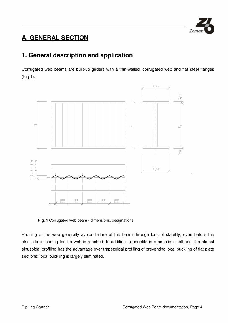
Corrugated web beams are built-up girders with a thin-walled, corrugated web and flat steel flanges
(Fig 1).
Fig. 1 Corrugated web beam - dimensions, designations
Profiling of the web generally avoids failure of the beam through loss of stability, even before the
plastic limit loading for the web is reached. In addition to benefits in production methods, the almost
sinusoidal profiling has the advantage over trapezoidal profiling of preventing local buckling of flat plate
sections; local buckling is largely eliminated.
Dipl.Ing.Gartner Corrugated Web Beam documentation, Page 5
Corrugated web beams may be used as beams (roof or slab beams, frame transoms) or as
components subjected to axial forces (columns or frame stanchions) virtually without limitations in
terms of construction. The optimal area of application is in steel structural engineering wherever rolled
profiles with greater than 300 mm structural height or low lattice girders of structural height below
approx. 1 800 mm were formerly used.
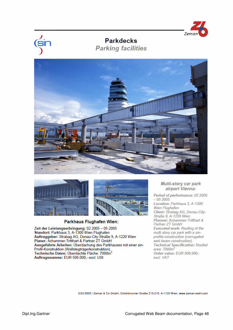
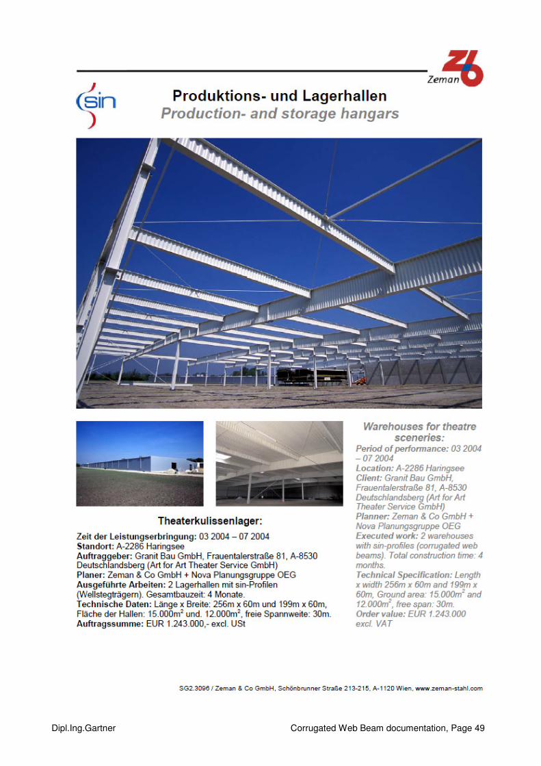
Practical examples – see Section 19

Dipl.Ing.Gartner Corrugated Web Beam documentation, Page 6
2. Basis for calculation
As a result of the profiling, the web largely does not participate in the transfer of axial normal bending
stresses. This means that,
in static terms, the corrugated web beam corresponds to a lattice girder
in which the bending moments and normal forces are transferred via the flanges only, whilst the
transverse forces are transferred only through the diagonals and verticals of the lattice girder - in this
case the corrugated web.
Dimensioning and verification is based on this static model and carried out in accordance with
EN 1993-1-1 and EN 1993-1-5 Annex D, according to the E-P (E-E) method. Accordingly, verification
of the load bearing capacity is best performed based on internal forces and the cross section
resistances of the individual components of the cross section - flange and web.
Alternatively, calculations may of course also be based on any national regulatory standards for lattice
girders or open web columns and for transverse buckling of orthotropic plates.
The determination of the resistance values for the corrugated web beam is described in detail in
Section 8, based essentially on the verification formats in EN 1993-1-5 Annex and dealing specifically
with corrugated web beams. The procedure is furthermore backed up by a number of experimental
results ([8]...[10]) and expert opinions [6] and [7]*).
*) Since these expert opinions were written before the publication of EN 1993-1-1 (5), the formulae for bearing
loads of the flanges (Section 4) referred to therein do not agree exactly with those of the aforementioned standards. However, comparative calculations have shown that the results in the relevant areas of dimensioning and application are in good agreement.
Dipl.Ing.Gartner Corrugated Web Beam documentation, Page 7
3. Product range and designation
Standard girders comprise the selected webs and flat steel flanges, usually with identically
dimensioned upper and lower flanges.
Web dimensions:
The standard coil widths are 1 000 mm / 1 250 mm / 1 500 mm. Splitting the standard coil widths
produces the following standard web heights:
Web heights: 333, 500, 625, 750, 1 000, 1 250, 1 500 mm
Web thickness: 1.50; 2.00; 2.50; 3.00; 4.00; 5.00; 6.00 mm
With material quality S235 and S355.
0 … 1.5mm / A … 2.0mm / B … 2.5mm / C … 3.0mm / D … 4.0mm / E … 5.0mm / F … 6.0mm
Flanges:
min. w = 120 mm max. w = 450 mm
min. t = 6 mm max. t = 30 mm
With material quality S235 and S355.

Dipl.Ing.Gartner Corrugated Web Beam documentation, Page 8
Parallel flange corrugated web beam
Lengths supplied:
These depend on the available machines, which varies from one supplier to the next.
min. 4 000 mm
max. 20 000 mm
Maximum dimensions for construction elements:
see Construction details, Sheets 1.3 and 1.4 (Appendix C).
Designations:
WT [web] [height] / [width] x [thickness]
Example: WT A 1000 / 300x15
Different upper flanges (UF) and lower flanges (LF) are possible. For manufacturing reasons, the
flange widths should be the same.
wUP = wLF ; tUF ≠≠≠≠ tLF
By exception, however, wUF = wLF ± 50 mm is possible, with the same flange thickness.
Example: WT B 1 250 / 300x15 / 300x12

Dipl.Ing.Gartner Corrugated Web Beam documentation, Page 9
Conical corrugated web beam
Manufacture
Two conical beams can be manufactured from one standard height beam. Using a cutting torch, the
web is cut at an angle to the flanges, such that the heights are the same on both sides.
Lengths supplied + dimension:
min. 4 000 mm
max. 12 000 mm
For reasons of manageability, the following standard combinations are defined:
Based on the 1 500 mm original beam, the combinations are:
1 250+250 / 1 200+300 / 1 150+350 / 1 100+400 / 1 050+450 / 1 000+500
Based on the 1 250 mm original beam, the combinations are:
1 000+250 / 950+300 / 900+350 / 850+400 / 800+450
Based on the 1 000 mm original beam, the combinations are:
750+250 / 700+300 / 650+350 /
Any other combinations can in principle be produced, provided they meet the limiting conditions.
Dipl.Ing.Gartner Corrugated Web Beam documentation, Page 10
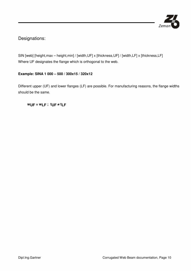
Designations:
SIN [web] [height,max – height,min] / [width,UF] x [thickness,UF] / [width,LF] x [thickness,LF]
Where UF designates the flange which is orthogonal to the web.
Example: SINA 1 000 – 500 / 300x15 / 320x12
Different upper (UF) and lower flanges (LF) are possible. For manufacturing reasons, the flange widths
should be the same.
wUF = wLF ; tUF ≠≠≠≠ tLF

Dipl.Ing.Gartner Corrugated Web Beam documentation, Page 11
4. Material
Standard product range:
Flange: wide flat steel or steel lamellas
S235J0 or JR in accordance with EN 10 025-2
S355J2 in accordance with EN 10 025-2
Web: cold- or hot-rolled sheet in accordance with EN 10 025-2
Special qualities:
For the purposes of material procurement, all other qualities of steel are deemed special qualities.
Sheet material with higher yield strengths up to 320 N/mm² (StE 320) can also be utilized for the web.
Longer delivery times due to material procurement time and minimum order quantities would apply,
however.
5. Tolerances
For the completed construction: EN 1090-2
6. Corrosion protection
Corrosion protection through coatings:
The finished beam is factory coated approximately 40 µm thick. Any other or additional primers or top
coatings which may be required must be separately agreed to in the order. Standard colors are
indicated in the price list as amended.
In the standard design, the web plate is welded to the flanges using a continuous fillet weld on one
side. An additional zinc primer coating is applied on the non-welded side of the web, in the throat
region.
Corrosion protection by hot galvanizing:
The corrugated web beam is easy to hot-galvanize.

Dipl.Ing.Gartner Corrugated Web Beam documentation, Page 12
7. Quality monitoring
The manufacture is subject to constant and documented internal monitoring.
The quality of the original material is verified through factory certificates pursuant to
EN 10 204 Clause 2.2. Any additional factory certificates must be agreed on at the time the material is
reserved.
The factory is EN 3834 certified and has the “Großer Eignungsnachweis” [Certificate for Manufacturer
Qualification for Welding Steel Structures] pursuant to DIN 18 800, Part 7, Section 6.2, DIN 4132 and
DIN 8563 Part 10 (issued by SLV, Berlin) for welding techniques (E) and (MAG). Procedural tests are
furthermore available for welding of the flanges using the MAG protective gas welding method and for
stud welding.
All the tests are in respect of basic materials of quality classes S235 and S355.
The current certificates can be presented on request.

Dipl.Ing.Gartner Corrugated Web Beam documentation, Page 13
B. TECHNICAL SECTION
8. Load bearing capacity of webs and flanges
Transverse force load bearing capacity of the webs (EN 1993-1-5 Annex D)
The shear load bearing capacity RdV is defined as follows acc. to EN 1993-1-5:
ww
M
yw
cRd fhf
V31γ
χ=
cχ ... is the smaller of the reduction factor for local buckling of plates lc ,χ and for buckling gc,χ .
The reduction factor for local buckling of plates gc,χ is determined as follows:
0,19,0
15,1
,
, ≤+
=lc
lcλ
χ
with
3,
,
lcr
y
lc
f
τλ =
lcr ,τ is for sinusoidal webs
( )
2
2
23
,112
34,5
−
+=
s
tE
th
sa w
ww
lcrν
πτ
Tests have shown that local buckling is not significant.

Dipl.Ing.Gartner Corrugated Web Beam documentation, Page 14
s half the developed length of the length of the corrugation wave
w half the projected length of a corrugation wavelength mmw 155=
3a the height of the projected amplitude
Fig. 2 Significant web dimensions
s is determined by numerical integration over the actual profiling form
dxw
x
w
as
w
∫
+=
0
2
3 2sin1
ππ
for mmtw 5.25.1 −= ⇒ mma 403 =
for mmtw 3= ⇒ mma 433 =
The reduction factor for buckling of the web is calculated as follows:
The corrugated web is considered an orthotropic plate with rigidities Dx and Dz. The following therefore
applies to the corrugated web:
s
w.
tEx
)1(12
.2
3
ν−=D ;
w
IE zz
.=D for Dx << Dy
with the second moment of inertia of a profiled section of length w
dxw
xattI
w
wwz ∫
+=
0
2
33 2sin
212
1 π
Dipl.Ing.Gartner Corrugated Web Beam documentation, Page 15
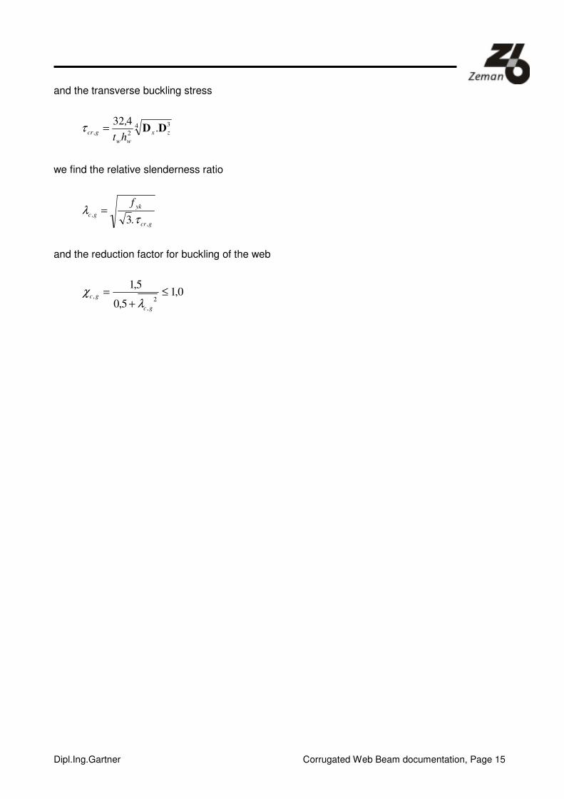
and the transverse buckling stress
4 3
2, .432
zx
ww
gcrht
,DD=τ
we find the relative slenderness ratio
gcr
yk
gc.
f
,
,3 τ
λ =
and the reduction factor for buckling of the web
0,15,0
5,1
2
,
, ≤+
=
gc
gc
λχ

Dipl.Ing.Gartner Corrugated Web Beam documentation, Page 16
Normal force load bearing capacity of flanges
In determining the normal load bearing capacity of the flanges, the tensile and compressive stresses
are considered separately.
In the case of tensile stress, the load bearing capacity of the flange is derived as follows:
g, .t.bfgykRkg
=N ; MRkgRdgγ,, NN =
The stability of the flange must be considered under compressive stress. A distinction must be made
here between local buckling of the flanges and the overall stability (buckling transverse to the axis of
the beam = torsional-flexural buckling).
For local buckling, the actually effective area of the flange under compressive stress is determined
(EN 1993-1-5 Clause 4.4).
ceffcAA ⋅= ρ,
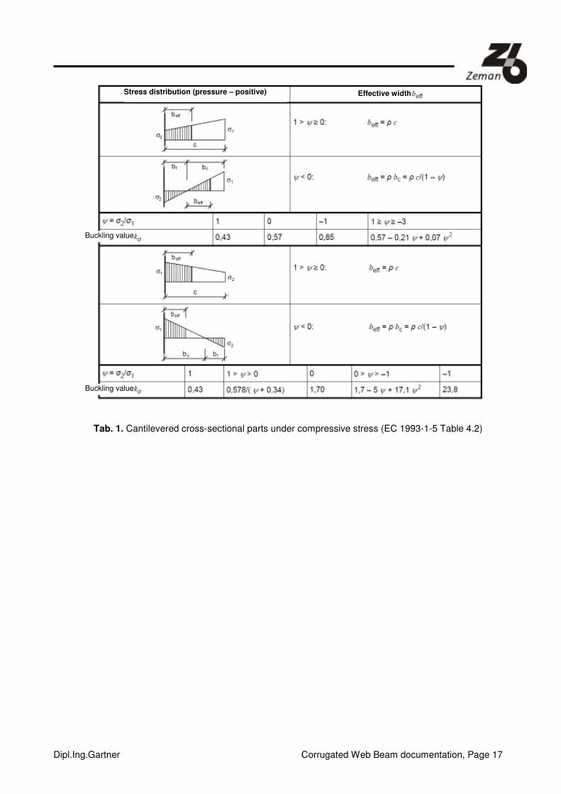
The following table gives the effective areas for cantilevered cross-sectional parts:
Dipl.Ing.Gartner Corrugated Web Beam documentation, Page 17
Tab. 1. Cantilevered cross-sectional parts under compressive stress (EC 1993-1-5 Table 4.2)
Stress distribution (pressure – positive) Effective width
Buckling value
Buckling value
Dipl.Ing.Gartner Corrugated Web Beam documentation, Page 18
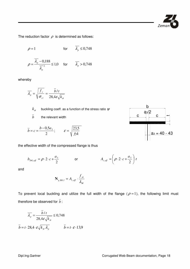
The reduction factor ρ is determined as follows:
1=ρ for 748,0≤pλ
0,1188,0
2≤
−=
p
p
λ
λρ for 748,0>pλ
whereby
σεσλ
k
tbf
cr
y
p4,28
/==
σk buckling coeff. as a function of the stress ratio ψ
b the relevant width
2
5,0 3abcb
−== ;
fyk
5,23=ε
the effective width of the compressed flange is thus
22 3
,
acb effDG +⋅⋅= ρ or t
acA effc ⋅
+⋅⋅=
22 3
, ρ
and
M
yk
effclRdg
fA
λ⋅= ,,,N
To prevent local buckling and utilize the full width of the flange ( 1=ρ ), the following limit must
therefore be observed for b :
748,04,28
/≤=
σελ
k
tbp
pktb λε σ⋅⋅= 4,28 9,13⋅⋅= εtb
a3 = 40 - 43
cca3/2
b
t
Dipl.Ing.Gartner Corrugated Web Beam documentation, Page 19
9,132
5,0 3 ⋅⋅=−
== εtab
cb
3lim 5,09,132 atb +⋅⋅⋅= ε
Dipl.Ing.Gartner Corrugated Web Beam documentation, Page 20
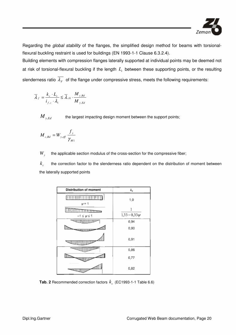
Regarding the global stability of the flanges, the simplified design method for beams with torsional-
flexural buckling restraint is used for buildings (EN 1993-1-1 Clause 6.3.2.4).
Building elements with compression flanges laterally supported at individual points may be deemed not
at risk of torsional-flexural buckling if the length cL between these supporting points, or the resulting
slenderness ratio Fλ of the flange under compressive stress, meets the following requirements:
Edy
Rdcc
zf
ccf
M
M
i
Lk
,
,0
1,
⋅≤⋅
⋅= λ
λλ
EdyM , the largest impacting design moment between the support points;
1
,,
M
y
effyRdc
fWM
γ=
yW the applicable section modulus of the cross-section for the compressive fiber;
ck the correction factor to the slenderness ratio dependent on the distribution of moment between
the laterally supported points
Tab. 2 Recommended correction factors ck (EC1993-1-1 Table 6.6)
Distribution of moment

Dipl.Ing.Gartner Corrugated Web Beam documentation, Page 21
zfi , the radius of gyration of the flange under compressive stress around the weak cross-sectional
axis.
0cλ the limiting slenderness ratio for the above element under compressive stress;
επλ 9,931 ==yf
E
yf
235=ε ( yf in N/mm²)
1,00,0 += LTc λλ 4,00, =LTλ (max. value acc. to EN1993-1-1 6.3.2.3)
For Class 4 cross sections, zfi , may be calculated as follows:
feff
feff
zfA
Ii
,
,
, =
whereby
feffI , the effective second moment of inertia of the flange under compressive stress around
the weak cross-sectional axis;
feffA , the effective area of the flange under compressive stress
The contribution of a third of the web plate section under compressive stress ( cweffA ,,3
1+ ) is ignored in
the case of the corrugated web beam.
Using the formula for the slenderness ratio of the flange, a lim,cL value can be determined above which
a global stability problem may occur.
Edy
Rdcc
zf
ccf
M
M
i
Lk
,
,0
1,
⋅≤⋅
⋅= λ
λλ EdyRdc MM ,, =
c
zfc
ck
iL
1,0
lim,
λλ ⋅⋅=
Global stability becomes important when lim,cc LL >

Dipl.Ing.Gartner Corrugated Web Beam documentation, Page 22
h
MN
Rdc
Rdc
,
, = ; h
MN
Edy
Edy
,
, =
Edy
Rdcc
zf
ccf
N
N
i
Lk
,
,0
1,
⋅≤⋅
⋅= λ
λλ
cc
zfRdcc
gRdgLk
iNN
⋅
⋅⋅⋅=
1,,0
,,
λλ
The load bearing capacity of the flange under compressive stress is therefore
( )gRdglRdgRdgrdg NNN ,,,,,, ;; min=N
Table 2 lists the load bearing capacities of the flanges for steel quality S235, as a function of the
spacing of the lateral supports for a constant normal force (kc = 1).
The local buckling limits applicable to the shown flange cross-sections are shown in Table 13. Other
application limits are:
� Clim
the spacing between lateral supports up to which the compressed flange can be
designed for the full elastic limiting load NgRk, without reduction, and
� cmax maximum spacing between lateral supports as given by a maximum slenderness
(transverse to the beam axis) ratio of 250.
Dipl.Ing.Gartner Corrugated Web Beam documentation, Page 23
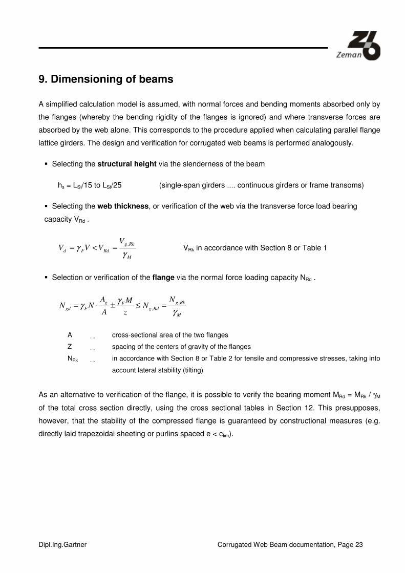
9. Dimensioning of beams
A simplified calculation model is assumed, with normal forces and bending moments absorbed only by
the flanges (whereby the bending rigidity of the flanges is ignored) and where transverse forces are
absorbed by the web alone. This corresponds to the procedure applied when calculating parallel flange
lattice girders. The design and verification for corrugated web beams is performed analogously.
� Selecting the structural height via the slenderness of the beam
hs = LSt/15 to LSt/25 (single-span girders .... continuous girders or frame transoms)
� Selecting the web thickness, or verification of the web via the transverse force load bearing
capacity VRd .
M
Rkg
RdFd
VVVV
γγ
,=<= VRk in accordance with Section 8 or Table 1
� Selection or verification of the flange via the normal force loading capacity NRd .
M
Rkg
RdgFg
Fgd
NN
z
M
A
ANN
γ
γγ ,
, =≤±⋅=
A .... cross-sectional area of the two flanges
Z .... spacing of the centers of gravity of the flanges
NRk .... in accordance with Section 8 or Table 2 for tensile and compressive stresses, taking into
account lateral stability (tilting)
As an alternative to verification of the flange, it is possible to verify the bearing moment MRd = MRk / γM
of the total cross section directly, using the cross sectional tables in Section 12. This presupposes,
however, that the stability of the compressed flange is guaranteed by constructional measures (e.g.
directly laid trapezoidal sheeting or purlins spaced e < clim).
Dipl.Ing.Gartner Corrugated Web Beam documentation, Page 24
� Verification of serviceability
This must be provided by verification of deflections. Shear deformation must be taken into account in
this respect. The cross sectional tables in Section 12 give details of the “transverse force area” AQ,
and/or the ratio A/AQ, as required by many computation programs, to allow the shear flexibility to be
included when determining deformations and cross sectional forces.
� Verification of the load introduction points
See Section 11

Dipl.Ing.Gartner Corrugated Web Beam documentation, Page 25
10. Dimensioning of columns
When dimensioning columns, the static model of a multi-part compression member of the lattice or
frame-stanchion type is assumed. As with bending girders, the normal force is distributed only to the
flanges and the corrugated web serves to transfer only shear forces between flanges. Allowance must
therefore be made for the shear flexibility of the web when verifying buckling in the direction of the
“strong” axis (equivalent to the non-material axis in the case of multi-part compression members), e.g.
by introducing ideal slenderness.
λ λ λid y= +212 with λy
ky
y
=s
i and
λπ π
12
2 2
25 9= = =. .
. .
. .
., .
E A
G t h
E A
G A
A
As s s s Q Q
The buckling verification around the “weak” axis, or the torsional-flexural buckling verification may be
carried out, to be on the safe side, on the “isolated“ flange by referring to Table 2.
11. Verification of local load introduction
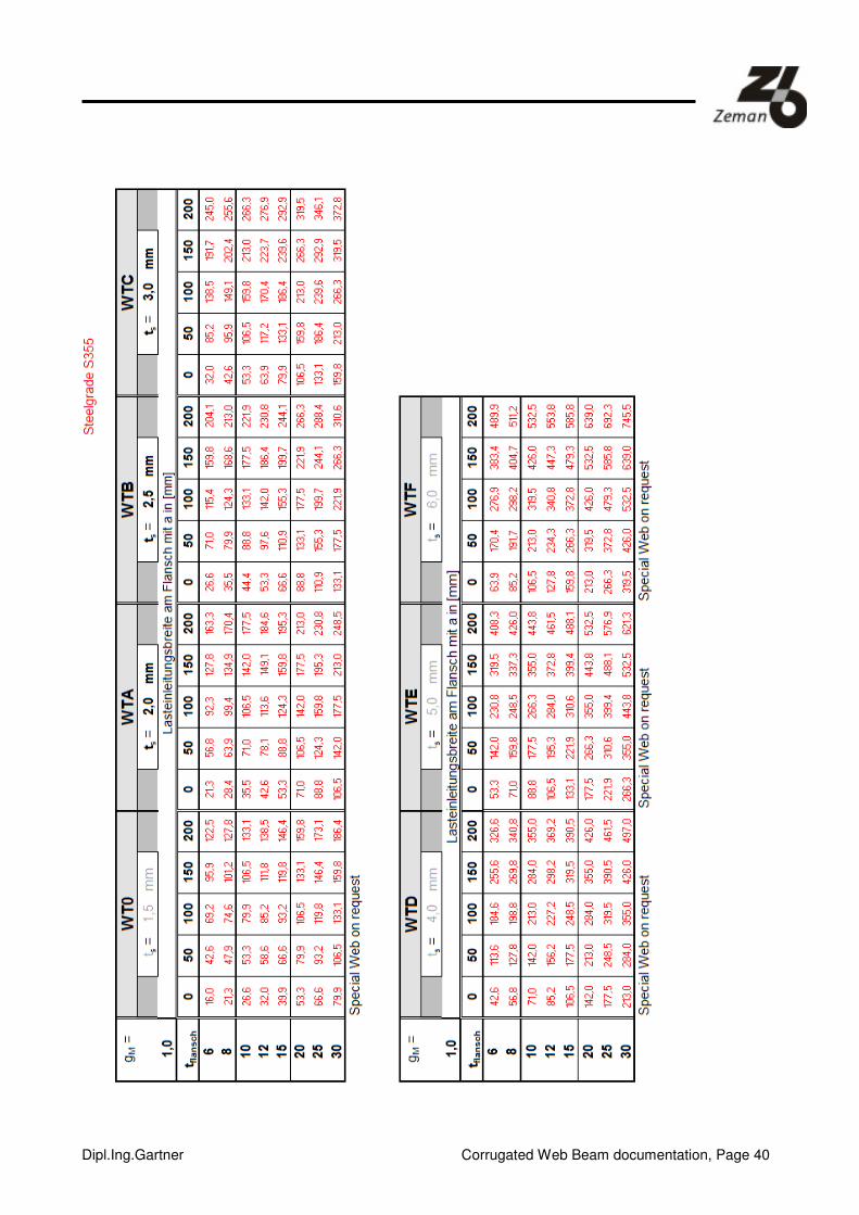
Tests have shown that the assumption of
( )ykgsRk ftat ..5+=P
is the safe side.
Fig. 2: Load introduction into the corrugated web without stiffener
Load distribution width
Web plate thickness ts
Dipl.Ing.Gartner Corrugated Web Beam documentation, Page 26
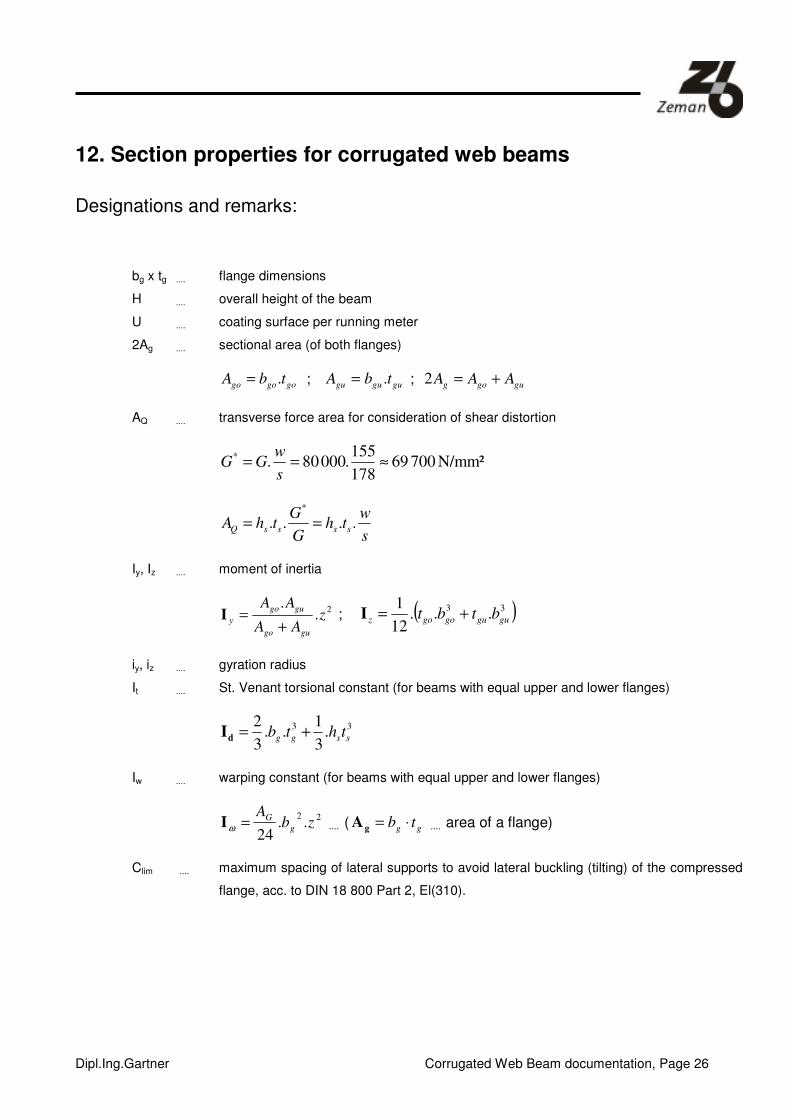
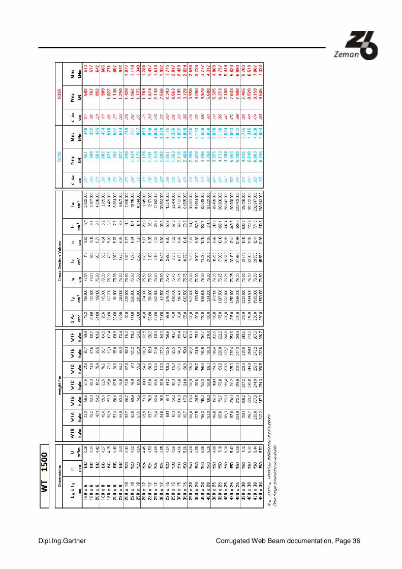
12. Section properties for corrugated web beams
Designations and remarks:
bg x tg .... flange dimensions
H .... overall height of the beam
U .... coating surface per running meter
2Ag .... sectional area (of both flanges)
gogogo tbA .= ; gugugu tbA .= ; gugog AAA +=2
AQ .... transverse force area for consideration of shear distortion
N/mm² 700 69178
155.000 80.
* ≈==s
wGG
s
wth
G
GthA ssssQ ....
*
==
Iy, Iz .... moment of inertia
2.
.z
AA
AA
gugo
gugo
y+
=I ; ( )33...
12
1gugugogoz btbt +=I
iy, iz .... gyration radius
It .... St. Venant torsional constant (for beams with equal upper and lower flanges)
33.
3
1..
3
2ssgg thtb +=dI
Iw .... warping constant (for beams with equal upper and lower flanges)
22..
24zb
Ag
G=ωI .... ( gg tb ⋅=gA .... area of a flange)
Clim .... maximum spacing of lateral supports to avoid lateral buckling (tilting) of the compressed
flange, acc. to DIN 18 800 Part 2, El(310).

Dipl.Ing.Gartner Corrugated Web Beam documentation, Page 27
13. Standards and Expert Opinions:
[1] EN 1993 -1 -1
[2] EN 1993 -1- 5
[3] EN 1993 -1 – 5, Annex D
[4] O.Univ. Prof. D.I. Dr. Günter Ramberger, Gutachten über die Berechnung von geschweißten I-
Trägern mit Stegen aus gewellten Blechen, Wien 20.12.1989.
[Expert Opinion on the calculation of welded I-beams with corrugated webs, Vienna 12.20.1989]
[5] O.Univ. Prof. D.I. Dr. Günter Ramberger, 2. Gutachten über die Berechnung von geschweißten I-
Trägern mit Stegen aus gewellten Blechen, Wien 16.11.1990.
[2nd Expert Opinion on the calculation of welded I-beams with corrugated webs, Vienna
11.16.1990]
[6] Test reports on experiments carried out on I-beams with corrugated web plates, Vienna
University of Technology, Institute for Steel Construction, Dept of Applied Model Statics in Steel
Construction, August 1990. [in German]
[7] Report no. 943040: Untersuchung zur Einleitung dynamischer Lasten in Wellstegträger WTB 750
- 300x12, Versuchsanstalt für Stahl, Holz und Steine (Amtl. Materialprüfanstalt) Universität
Karlsruhe, 1995.
[Investigation into the introduction of dynamic loads into corrugated web beams WTB 750 –
300x12, Experimental Institute for Steel, Timber and Brick (official testing institute), University of
Karlsruhe, 1995]
[8] Fire tests on corrugated web beams, Institute for Fire Prevention Technology and Safety
Research (officially authorized testing and experimental institute), Linz 1995. [in German]
[9] Final report on the bearing performance of corrugated web beams; Brandenburg University of
Technology, Chair of Steel Construction, Cottbus 1996. [in German]
[10] Gutachterliche Stellungnahme zur Querkrafttragfähigkeit von Wellstegträgern; Univ. Prof. Dr.-Ing.
habil. Hartmut Pasternak, Braunschweig/Cottbus 1996.
[Expert statement on the transverse force load bearing capacity of corrugated web beams]

Dipl.Ing.Gartner Corrugated Web Beam documentation, Page 28
References:
[13] Easley: Buckling Formulas for Corrugated Metal Shear Diaphragms. Journal of the Structural
Division, ASCE, No. ST 7, July 1975, pp. 1403-1417.
[14] Commentary to EN 1993-1-5
[15] Stahlbaukalender 2004 „Träger mit profilierten Stegen“
Dipl.Ing.Gartner Corrugated Web Beam documentation, Page 29
C. TABLES
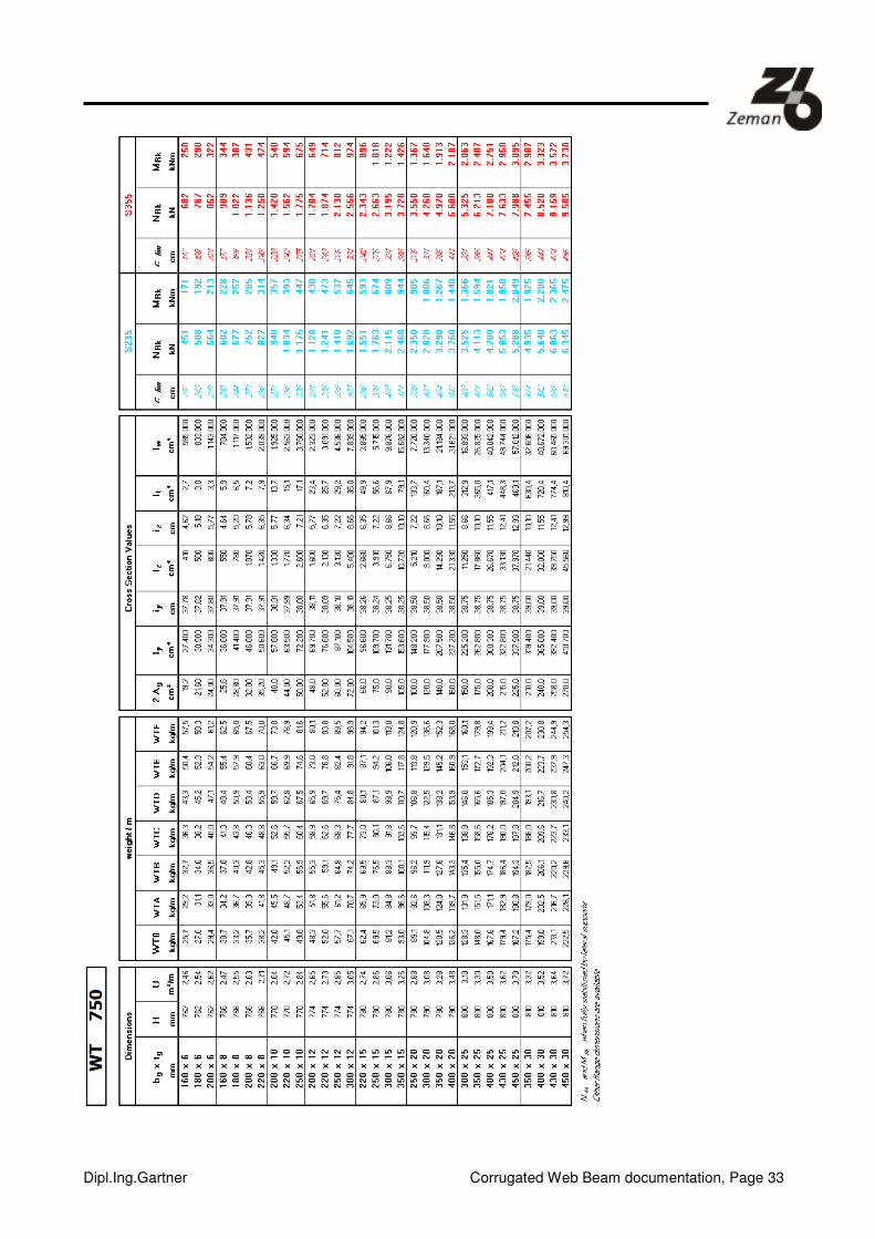
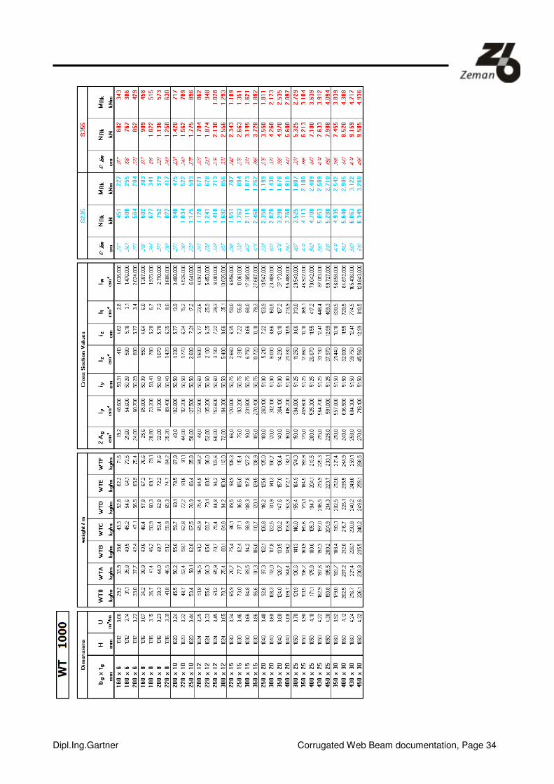
14. Section properties

Dipl.Ing.Gartner Corrugated Web Beam documentation, Page 30

Dipl.Ing.Gartner Corrugated Web Beam documentation, Page 31

Dipl.Ing.Gartner Corrugated Web Beam documentation, Page 32
Dipl.Ing.Gartner Corrugated Web Beam documentation, Page 33
Dipl.Ing.Gartner Corrugated Web Beam documentation, Page 34

Dipl.Ing.Gartner Corrugated Web Beam documentation, Page 35
Dipl.Ing.Gartner Corrugated Web Beam documentation, Page 36

Dipl.Ing.Gartner Corrugated Web Beam documentation, Page 37
15. Transverse load bearing capacity

Dipl.Ing.Gartner Corrugated Web Beam documentation, Page 38
Pale beams are normally discarded, since their web does not have the plastic load bearing capacity.

Dipl.Ing.Gartner Corrugated Web Beam documentation, Page 39
16. Concentrated load introduction
Dipl.Ing.Gartner Corrugated Web Beam documentation, Page 40

Dipl.Ing.Gartner Corrugated Web Beam documentation, Page 41
17. Flange load bearing capacity
Steel quality: S235

Dipl.Ing.Gartner Corrugated Web Beam documentation, Page 42
Steel quality: S355

Dipl.Ing.Gartner Corrugated Web Beam documentation, Page 43
18. Practical examples

Dipl.Ing.Gartner Corrugated Web Beam documentation, Page 44

Dipl.Ing.Gartner Corrugated Web Beam documentation, Page 45

Dipl.Ing.Gartner Corrugated Web Beam documentation, Page 46

Dipl.Ing.Gartner Corrugated Web Beam documentation, Page 47
Dipl.Ing.Gartner Corrugated Web Beam documentation, Page 48
Dipl.Ing.Gartner Corrugated Web Beam documentation, Page 49
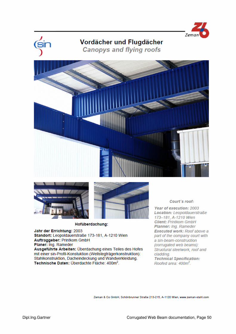
Dipl.Ing.Gartner Corrugated Web Beam documentation, Page 50

Dipl.Ing.Gartner Corrugated Web Beam documentation, Page 51

Dipl.Ing.Gartner Corrugated Web Beam documentation, Page 52
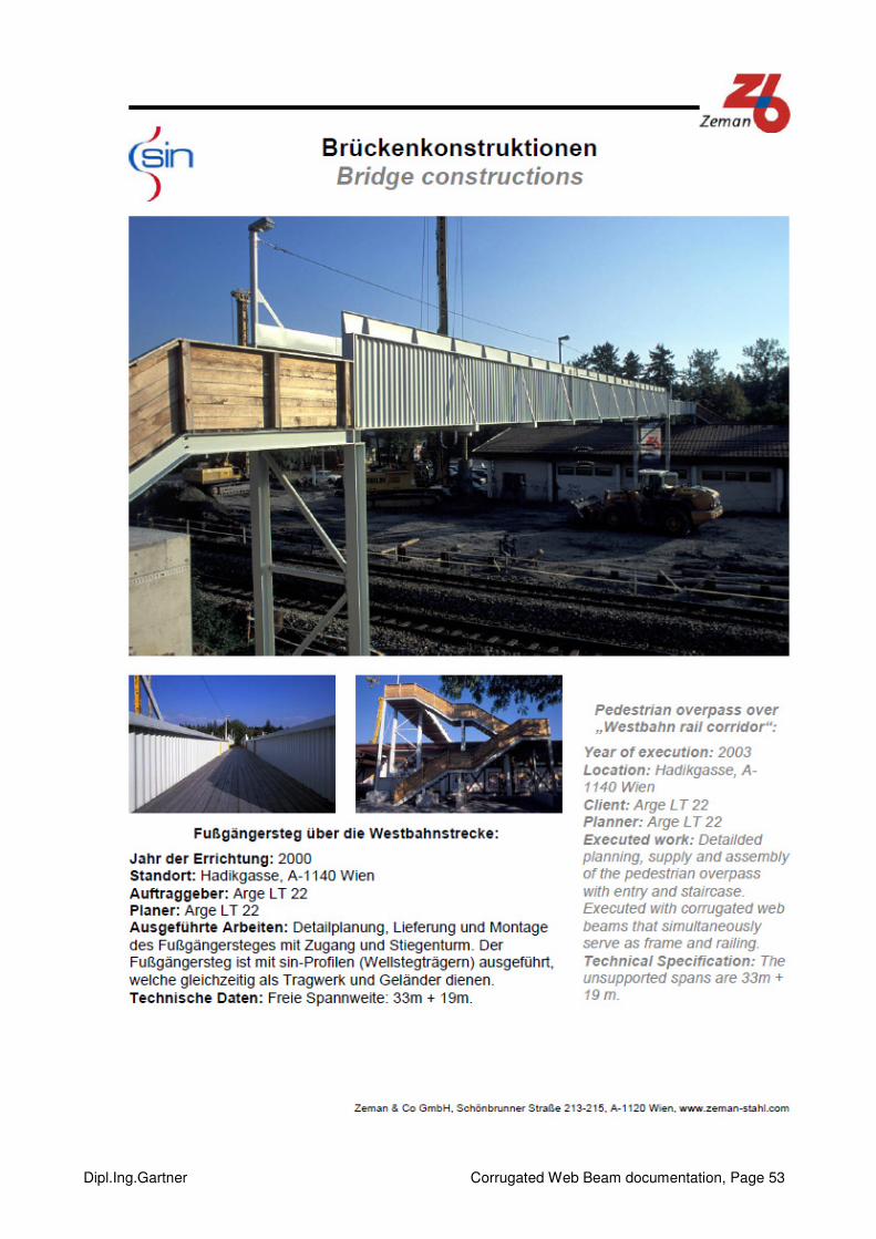
Dipl.Ing.Gartner Corrugated Web Beam documentation, Page 53
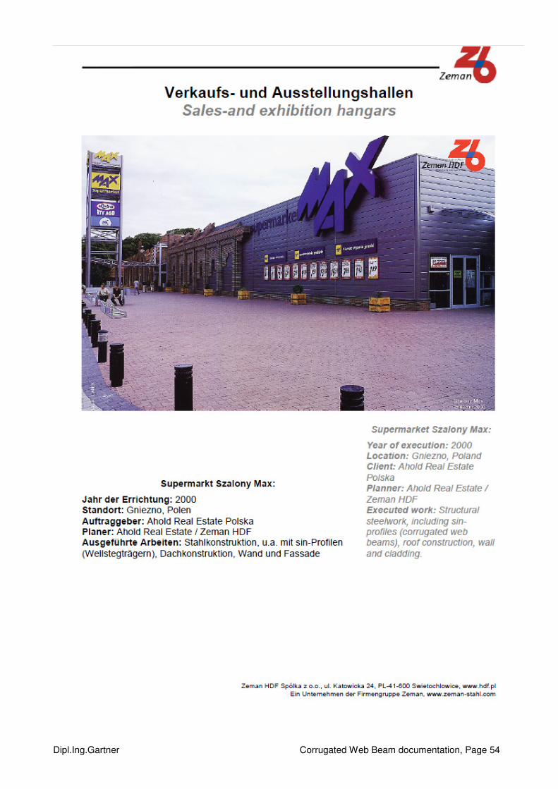
Dipl.Ing.Gartner Corrugated Web Beam documentation, Page 54
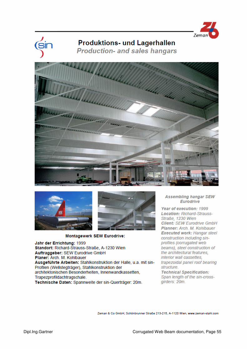
Dipl.Ing.Gartner Corrugated Web Beam documentation, Page 55

Dipl.Ing.Gartner Corrugated Web Beam documentation, Page 56
Dipl.Ing.Gartner Corrugated Web Beam documentation, Page 57


