16
PRODUCT INFORMATION Single- and multistage submersible pumps with canned motor Model series TCN / TCAM
P R O D U C T I N F O R M A T I O N
Single- and multistage submersible pumps with canned motor
Model series TCN / TCAM
General
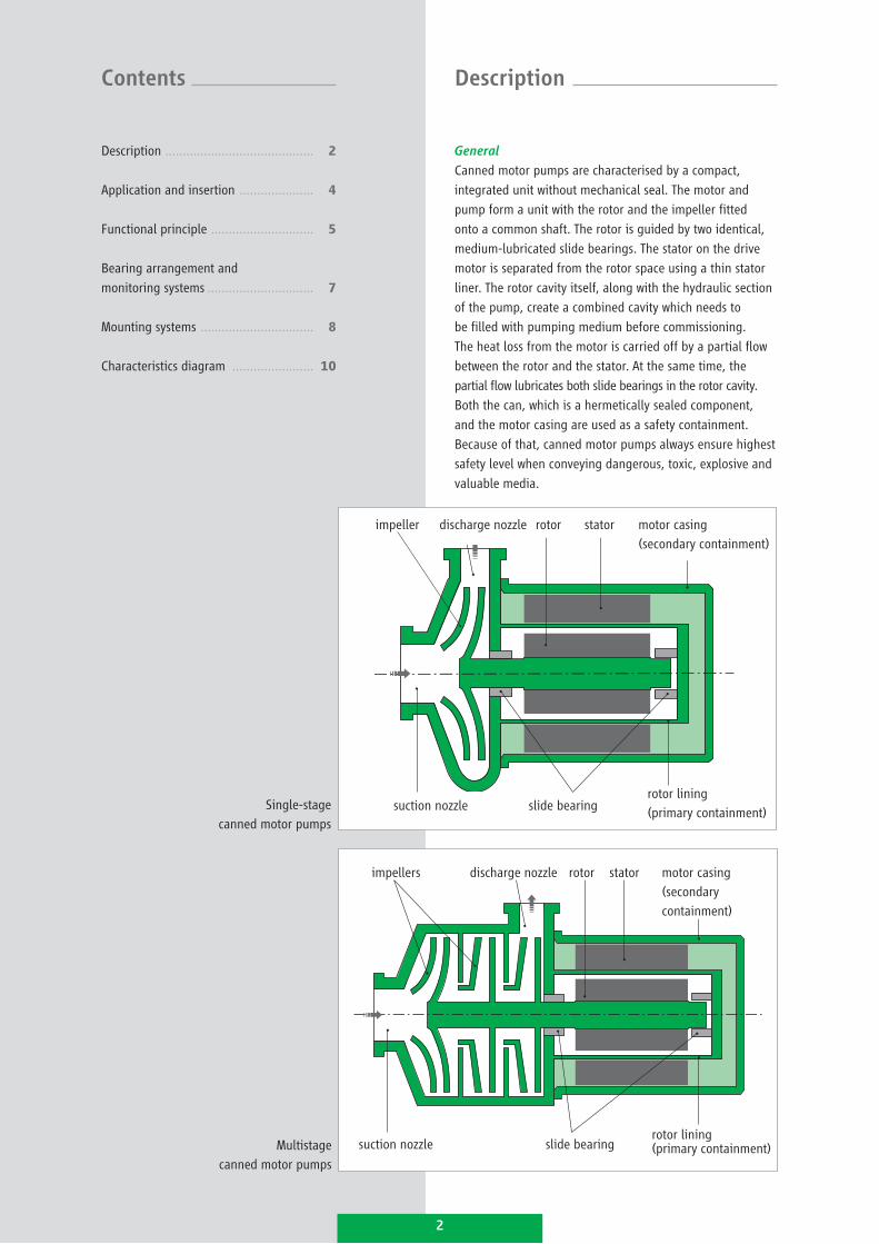
Canned motor pumps are characterised by a compact,
integrated unit without mechanical seal. The motor and
pump form a unit with the rotor and the impeller fitted
onto a common shaft. The rotor is guided by two identical,
medium-lubricated slide bearings. The stator on the drive
motor is separated from the rotor space using a thin stator
liner. The rotor cavity itself, along with the hydraulic section
of the pump, create a combined cavity which needs to
be filled with pumping medium before commissioning.
The heat loss from the motor is carried off by a partial flow
between the rotor and the stator. At the same time, the
partial flow lubricates both slide bearings in the rotor cavity.
Both the can, which is a hermetically sealed component,
and the motor casing are used as a safety containment.
Because of that, canned motor pumps always ensure highest
safety level when conveying dangerous, toxic, explosive and
valuable media.
Description
Description .......................................... 2
Application and insertion ..................... 4
Functional principle ............................. 5
Bearing arrangement and
monitoring systems .............................. 7
Mounting systems ................................ 8
Characteristics diagram ....................... 10
Contents
impeller discharge nozzle rotor stator motor casing(secondary containment)
suction nozzle slide bearingrotor lining(primary containment)
impellers discharge nozzle rotor stator motor casing (secondary containment)
suction nozzle slide bearing rotor lining(primary containment)
Single-stagecanned motor pumps
Multistagecanned motor pumps
2
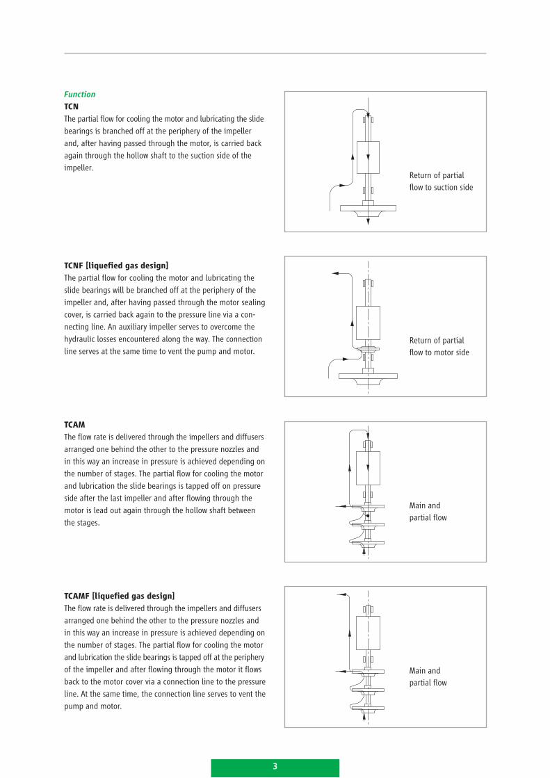
Function
TCN
The partial flow for cooling the motor and lubricating the slide
bearings is branched off at the periphery of the impeller
and, after having passed through the motor, is carried back
again through the hollow shaft to the suction side of the
impeller.
TCNF [liquefied gas design]
The partial flow for cooling the motor and lubricating the
slide bearings will be branched off at the periphery of the
impeller and, after having passed through the motor sealing
cover, is carried back again to the pressure line via a con-
necting line. An auxiliary impeller serves to overcome the
hydraulic losses encountered along the way. The connection
line serves at the same time to vent the pump and motor.
TCAM
The flow rate is delivered through the impellers and diffusers
arranged one behind the other to the pressure nozzles and
in this way an increase in pressure is achieved depending on
the number of stages. The partial flow for cooling the motor
and lubrication the slide bearings is tapped off on pressure
side after the last impeller and after flowing through the
motor is lead out again through the hollow shaft between
the stages.
TCAMF [liquefied gas design]
The flow rate is delivered through the impellers and diffusers
arranged one behind the other to the pressure nozzles and
in this way an increase in pressure is achieved depending on
the number of stages. The partial flow for cooling the motor
and lubrication the slide bearings is tapped off at the periphery
of the impeller and after flowing through the motor it flows
back to the motor cover via a connection line to the pressure
line. At the same time, the connection line serves to vent the
pump and motor.
Return of partial flow to suction side
Return of partial flow to motor side
Main and partial flow
Main and partial flow
3
Model series TCN / TCAM
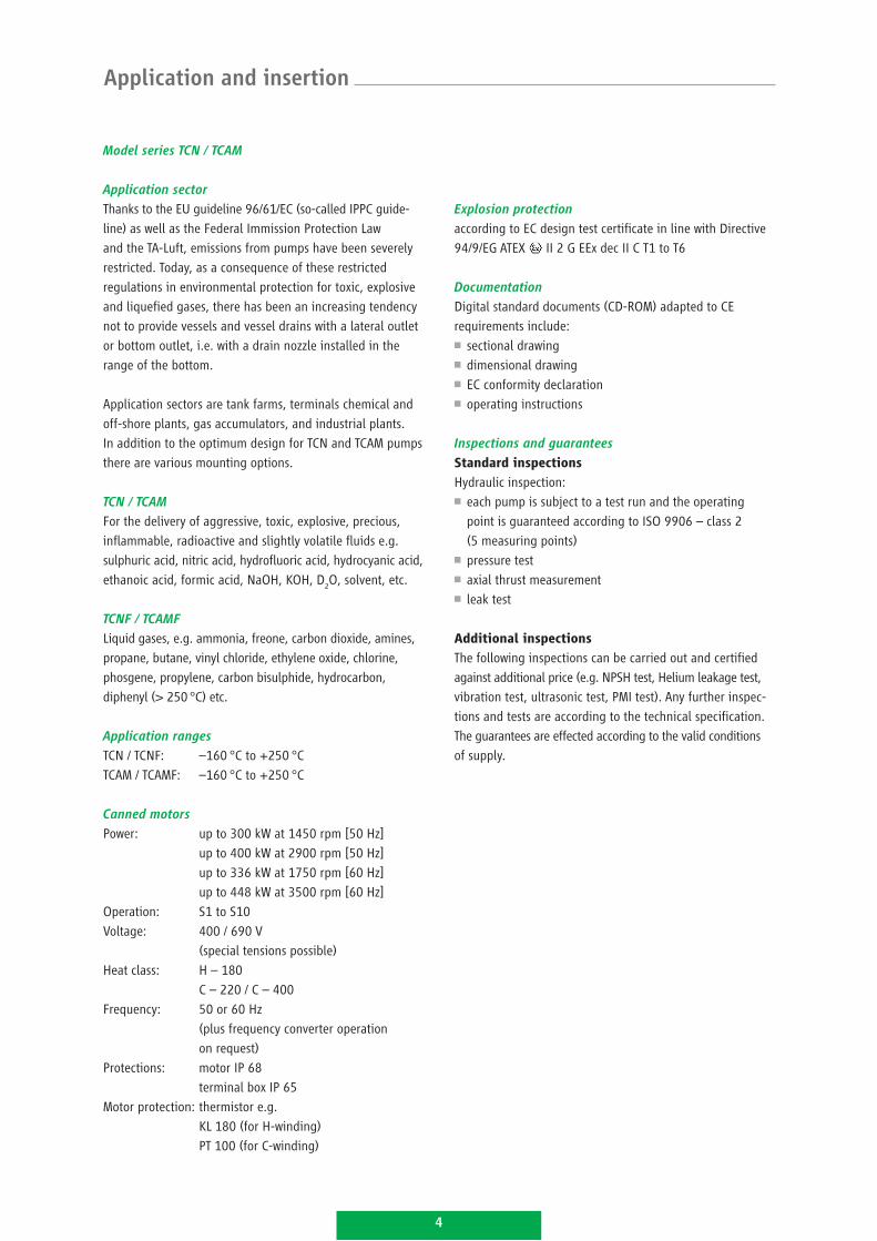
Application sector
Thanks to the EU guideline 96/61/EC (so-called IPPC guide-
line) as well as the Federal Immission Protection Law
and the TA-Luft, emissions from pumps have been severely
restricted. Today, as a consequence of these restricted
regulations in environmental protection for toxic, explosive
and liquefied gases, there has been an increasing tendency
not to provide vessels and vessel drains with a lateral outlet
or bottom outlet, i.e. with a drain nozzle installed in the
range of the bottom.
Application sectors are tank farms, terminals chemical and
off-shore plants, gas accumulators, and industrial plants.
In addition to the optimum design for TCN and TCAM pumps
there are various mounting options.
TCN / TCAM
For the delivery of aggressive, toxic, explosive, precious,
inflammable, radioactive and slightly volatile fluids e.g.
sulphuric acid, nitric acid, hydrofluoric acid, hydrocyanic acid,
ethanoic acid, formic acid, NaOH, KOH, D2O, solvent, etc.
TCNF / TCAMF
Liquid gases, e.g. ammonia, freone, carbon dioxide, amines,
propane, butane, vinyl chloride, ethylene oxide, chlorine,
phosgene, propylene, carbon bisulphide, hydrocarbon,
diphenyl (> 250 °C) etc.
Application ranges
TCN / TCNF: –160 °C to +250 °C
TCAM / TCAMF: –160 °C to +250 °C
Canned motors
Power: up to 300 kW at 1450 rpm [50 Hz]
up to 400 kW at 2900 rpm [50 Hz]
up to 336 kW at 1750 rpm [60 Hz]
up to 448 kW at 3500 rpm [60 Hz]
Operation: S1 to S10
Voltage: 400 / 690 V
(special tensions possible)
Heat class: H – 180
C – 220 / C – 400
Frequency: 50 or 60 Hz
(plus frequency converter operation
on request)
Protections: motor IP 68
terminal box IP 65
Motor protection: thermistor e.g.
KL 180 (for H-winding)
PT 100 (for C-winding)
Explosion protection
according to EC design test certificate in line with Directive
94/9/EG ATEX II 2 G EEx dec II C T1 to T6
Documentation
Digital standard documents (CD-ROM) adapted to CE
requirements include:
sectional drawing■■
dimensional drawing■■
EC conformity declaration■■
operating instructions■■
Inspections and guarantees
Standard inspections
Hydraulic inspection:
each pump is subject to a test run and the operating ■■
point is guaranteed according to ISO 9906 – class 2
(5 measuring points)
pressure test■■
axial thrust measurement■■
leak test ■■
Additional inspections
The following inspections can be carried out and certified
against additional price (e.g. NPSH test, Helium leakage test,
vibration test, ultrasonic test, PMI test). Any further inspec-
tions and tests are according to the technical specification.
The guarantees are effected according to the valid conditions
of supply.
Application and insertion
4
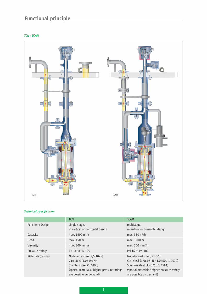
TCN / TCAM
TCN
Functional principle
TCAM
Technical specification
TCN TCAM
Function / Design single-stage, in vertical or horizontal design
multistage, in vertical or horizontal design
Capacity max. 1600 m3/h max. 350 m3/h
Head max. 150 m max. 1200 m
Viscosity max. 300 mm2/s max. 300 mm2/s
Pressure ratings PN 16 to PN 100 PN 16 to PN 100
Materials (casing) Nodular cast iron (JS 1025)Cast steel (1.0619+N)Stainless steel (1.4408) (special materials / higher pressure ratingsare possible on demand)
Nodular cast iron (JS 1025)Cast steel (1.0619+N / 1.0460 / 1.0570)Stainless steel (1.4571 / 1.4581)(special materials / higher pressure ratingsare possible on demand)
5
Advantages of hermetically sealed motor-driven
submersible pumps
The hydraulic part is arranged above close to the vessel bot-
tom. The pressure line is placed in parallel to the pump drive
shaft via manhole door to the outside. The impeller is arranged
at the shaft which is fixed by medium-lubricated guide bear-
ings. Depending on the immersion depth several bearings will
be required. The following reference value will apply: accord-
ing to the pump size, one guide bearing per 1,2 m to 1,6 m
is required. The bearings are installed in a support pipe that
is fixed to the manhole door. The sealing to the atmosphere
is effected by using a mechanical seal. The conventional drive
motor is installed outside the vessel and can be used for every
protection type according to the explosion requirements.
The basic and outer construction of a conventional pump with
mechanical seal can be compared with the design of a
submersible pump with magnetic drive. The difference of
sealing to the atmosphere is the containment shell of the
magnetic coupling that is directly installed to the pump
component. The containment shell ensures an absolute
leakage-free pump operation and can also be installed on
the outside of the vessel.
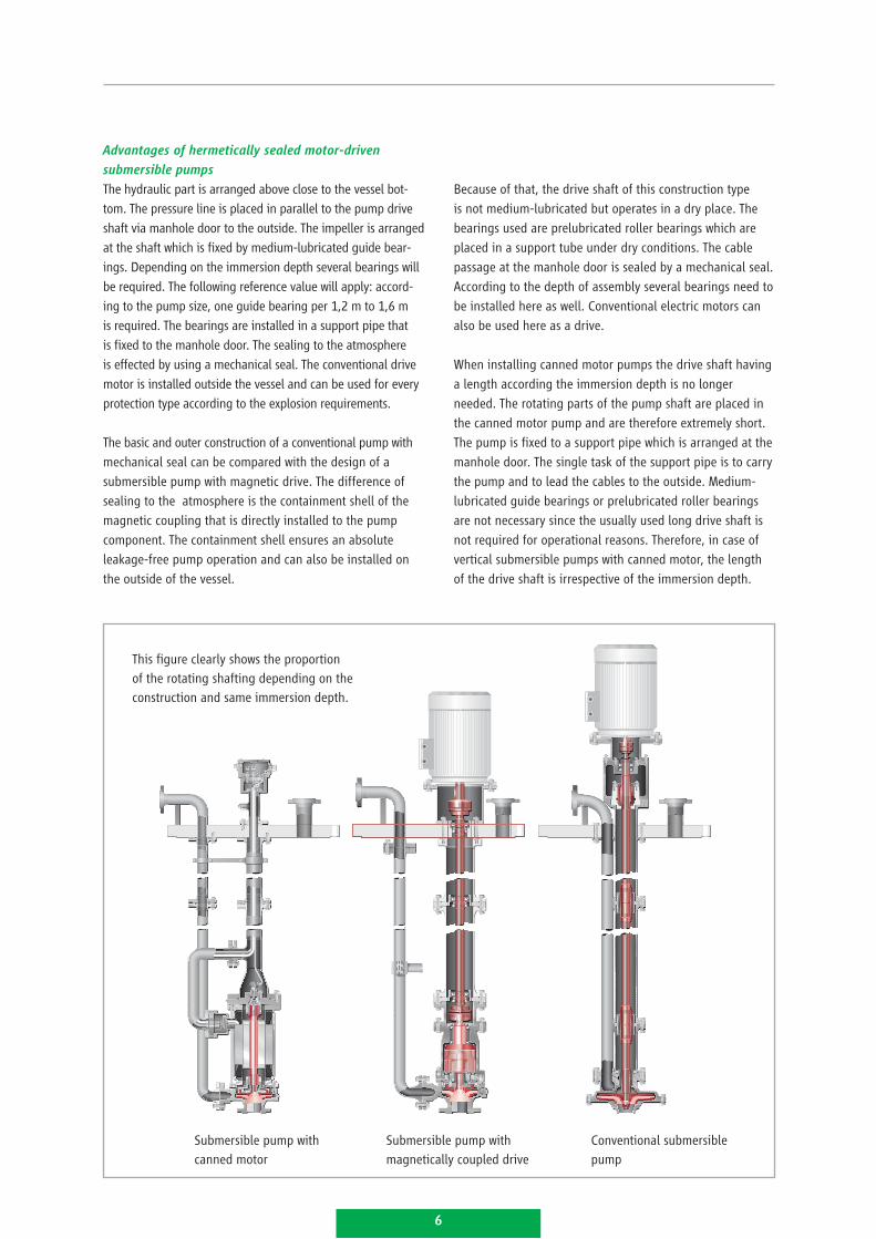
This figure clearly shows the proportion of the rotating shafting depending on the construction and same immersion depth.
Submersible pump with canned motor
Submersible pump with magnetically coupled drive
Conventional submersible pump
6
Because of that, the drive shaft of this construction type
is not medium-lubricated but operates in a dry place. The
bearings used are prelubricated roller bearings which are
placed in a support tube under dry conditions. The cable
passage at the manhole door is sealed by a mechanical seal.
According to the depth of assembly several bearings need to
be installed here as well. Conventional electric motors can
also be used here as a drive.
When installing canned motor pumps the drive shaft having
a length according the immersion depth is no longer
needed. The rotating parts of the pump shaft are placed in
the canned motor pump and are therefore extremely short.
The pump is fixed to a support pipe which is arranged at the
manhole door. The single task of the support pipe is to carry
the pump and to lead the cables to the outside. Medium-
lubricated guide bearings or prelubricated roller bearings
are not necessary since the usually used long drive shaft is
not required for operational reasons. Therefore, in case of
vertical submersible pumps with canned motor, the length
of the drive shaft is irrespective of the immersion depth.
Bearing arrangement
The bearing in hermetically designed pumps must be located
and immersed in the operating liquid. Therefore, in most
cases, only the use of hydrodynamic slide bearings is required.
The correct operating method ensures the advantage that
no contact may be created between the bearing lining. Thus,
they are constantly running free from wear and maintenance.
Service life of 8 to 10 years can be easily achieved by using
HERMETIC pumps.
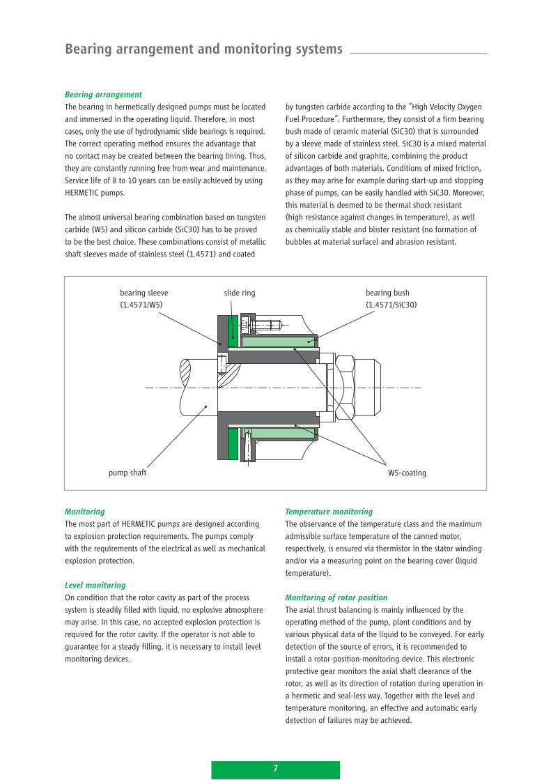
The almost universal bearing combination based on tungsten
carbide (W5) and silicon carbide (SiC30) has to be proved
to be the best choice. These combinations consist of metallic
shaft sleeves made of stainless steel (1.4571) and coated
bearing sleeve(1.4571/W5)
bearing bush(1.4571/SiC30)
slide ring
pump shaft
by tungsten carbide according to the “High Velocity Oxygen
Fuel Procedure“. Furthermore, they consist of a firm bearing
bush made of ceramic material (SiC30) that is surrounded
by a sleeve made of stainless steel. SiC30 is a mixed material
of silicon carbide and graphite, combining the product
advantages of both materials. Conditions of mixed friction,
as they may arise for example during start-up and stopping
phase of pumps, can be easily handled with SiC30. Moreover,
this material is deemed to be thermal shock resistant
(high resistance against changes in temperature), as well
as chemically stable and blister resistant (no formation of
bubbles at material surface) and abrasion resistant.
W5-coating
Monitoring
The most part of HERMETIC pumps are designed according
to explosion protection requirements. The pumps comply
with the requirements of the electrical as well as mechanical
explosion protection.
Level monitoring
On condition that the rotor cavity as part of the process
system is steadily filled with liquid, no explosive atmosphere
may arise. In this case, no accepted explosion protection is
required for the rotor cavity. If the operator is not able to
guarantee for a steady filling, it is necessary to install level
monitoring devices.
Temperature monitoring
The observance of the temperature class and the maximum
admissible surface temperature of the canned motor,
respectively, is ensured via thermistor in the stator winding
and/or via a measuring point on the bearing cover (liquid
temperature).
Monitoring of rotor position
The axial thrust balancing is mainly influenced by the
operating method of the pump, plant conditions and by
various physical data of the liquid to be conveyed. For early
detection of the source of errors, it is recommended to
install a rotor-position-monitoring device. This electronic
protective gear monitors the axial shaft clearance of the
rotor, as well as its direction of rotation during operation in
a hermetic and seal-less way. Together with the level and
temperature monitoring, an effective and automatic early
detection of failures may be achieved.
Bearing arrangement and monitoring systems
7
Mounting systems
The HERMETIC canned motor submersible pump provides the
optimum solution for difficult installations. Essentially there
are two different installations in the tank and in the vessel:
a) direct placing in the tank (figure 1)
b) installation of the pump with the opportunity to separate
the pump from the liquid in the vessel (figure 2)
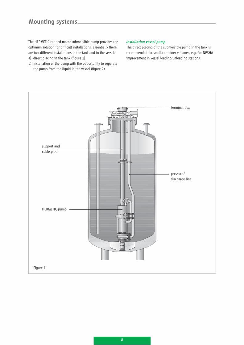
Figure 1
support andcable pipe
HERMETIC-pump
pressure / discharge line
terminal box
Installation vessel pump
The direct placing of the submersible pump in the tank is
recommended for small container volumes, e.g. for NPSHA
improvement in vessel loading/unloading stations.
8
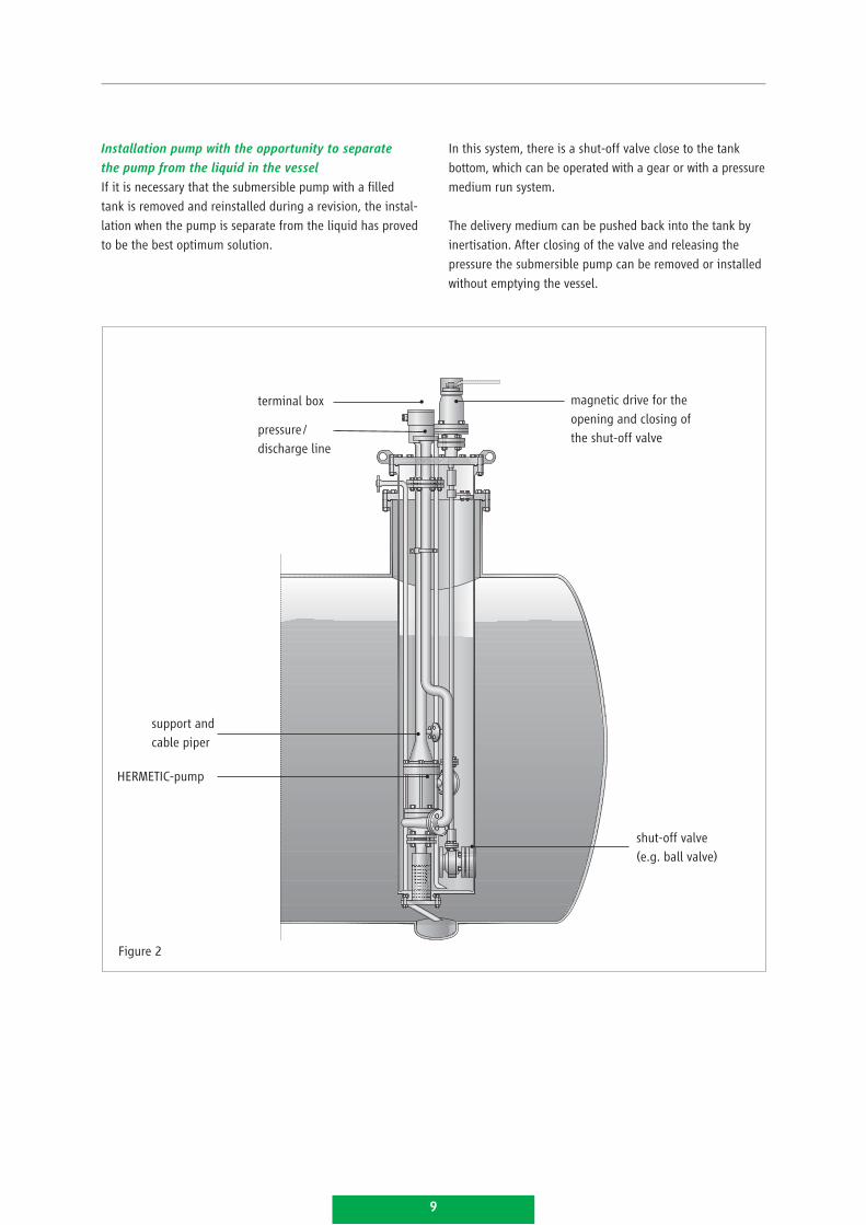
Installation pump with the opportunity to separate
the pump from the liquid in the vessel
If it is necessary that the submersible pump with a filled
tank is removed and reinstalled during a revision, the instal-
lation when the pump is separate from the liquid has proved
to be the best optimum solution.
In this system, there is a shut-off valve close to the tank
bottom, which can be operated with a gear or with a pressure
medium run system.
The delivery medium can be pushed back into the tank by
inertisation. After closing of the valve and releasing the
pressure the submersible pump can be removed or installed
without emptying the vessel.
Figure 2
support and cable piper
HERMETIC-pump
pressure / discharge line
terminal box magnetic drive for the opening and closing of the shut-off valve
shut-off valve (e.g. ball valve)
9
Characteristics diagram
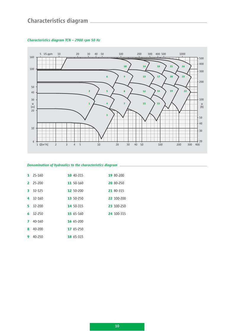
Characteristics diagram TCN – 2900 rpm 50 Hz
H[m]
H[ft]
1 25-160
2 25-200
3 32-125
4 32-160
5 32-200
6 32-250
7 40-160
8 40-200
9 40-250
10 40-315
11 50-160
12 50-200
13 50-250
14 50-315
15 65-160
16 65-200
17 65-250
18 65-315
19 80-200
20 80-250
21 80-315
22 100-200
23 100-250
24 100-315
Denomination of hydraulics to the characteristics diagram
1
2
3
4
5
6
7
8
9
10
11
12
13
14
15
16
17
18
19
20
21
22
23
24
50010 10020 30 40 50 200 300 400 1000
500
400
300
200
100
50
40
30
20Q[m3/h] 40030020010050403020105421
6
US.gpm5160
100
50
40
30
20
10
3
10
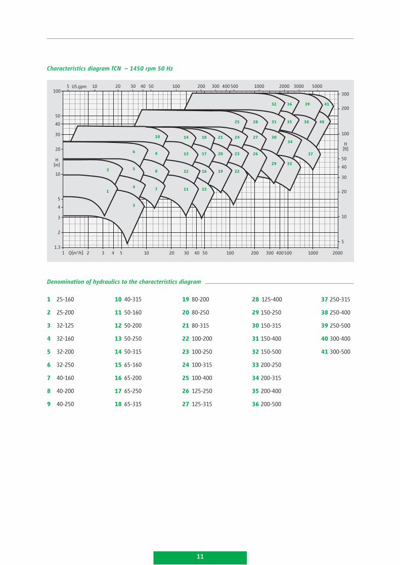
Characteristics diagram TCN – 1450 rpm 50 Hz
H[m]
H[ft]
US.gpm
1
2
3
4
5
6
7
8
9
10
11
12
13
14
15
16
17
18
19
20
21
22
23
24
25
26
27
28
29
30
31
32
33
34
35
36
38
39
40
41
37
1 25-160
2 25-200
3 32-125
4 32-160
5 32-200
6 32-250
7 40-160
8 40-200
9 40-250
10 40-315
11 50-160
12 50-200
13 50-250
14 50-315
15 65-160
16 65-200
17 65-250
18 65-315
19 80-200
20 80-250
21 80-315
22 100-200
23 100-250
24 100-315
25 100-400
26 125-250
27 125-315
28 125-400
29 150-250
30 150-315
31 150-400
32 150-500
33 200-250
34 200-315
35 200-400
36 200-500
37 250-315
38 250-400
39 250-500
40 300-400
41 300-500
10
Q[m3/h] 21 3 4 5 10 20 30 40 50 100 200 300 400500 1000 2000
2
1.3
3
4
5
10
20
30
40
50
1005 20 30 40 50 100 200 300 400 500 1000 2000
300
5000
200
100
50
40
30
20
10
5
3000
11
Denomination of hydraulics to the characteristics diagram
12
H[m]
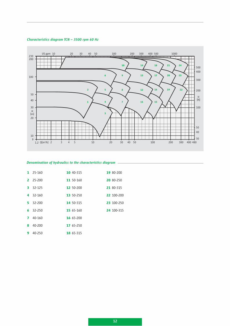
Characteristics diagram TCN – 3500 rpm 60 Hz
US.gpm
H[ft]
1 25-160
2 25-200
3 32-125
4 32-160
5 32-200
6 32-250
7 40-160
8 40-200
9 40-250
10 40-315
11 50-160
12 50-200
13 50-250
14 50-315
15 65-160
16 65-200
17 65-250
18 65-315
19 80-200
20 80-250
21 80-315
22 100-200
23 100-250
24 100-315
1
2
3
4
5
6
7
8
9
10
11
12
13
14
15
16
17
18
19
20
21
22
23
24
Q[m3/h] 21.2 3 4 5 10 20 30 40 50 100 200 300 400 48030
40
50
200
300
400
500
10005004003002001005040302010230200
100
50
40
30
20
109
100
Denomination of hydraulics to the characteristics diagram
13
H[m]
US.gpm
Q[m3/h] 21.2 3 4 5 10 20 30 40 50 100 200 300 400 500 1000 2000
10
100
50
40
30
20
10
5
4
3
2
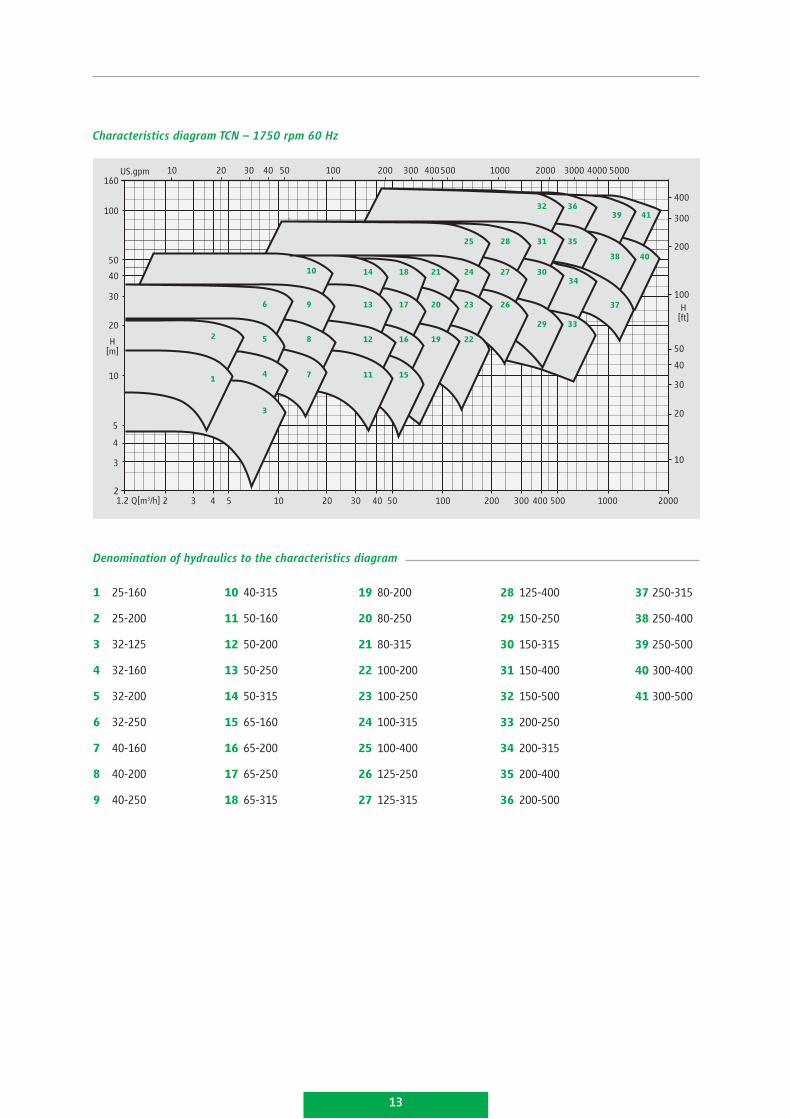
Characteristics diagram TCN – 1750 rpm 60 Hz
H[ft]
1
2
3
4
5
6
7
8
9
10
11
12
13
14
15
16
17
18
19
20
21
22
23
24
25
26
27
28
29
30
31
32
33
34
35
36
38
39
40
41
37
1 25-160
2 25-200
3 32-125
4 32-160
5 32-200
6 32-250
7 40-160
8 40-200
9 40-250
10 40-315
11 50-160
12 50-200
13 50-250
14 50-315
15 65-160
16 65-200
17 65-250
18 65-315
19 80-200
20 80-250
21 80-315
22 100-200
23 100-250
24 100-315
25 100-400
26 125-250
27 125-315
28 125-400
29 150-250
30 150-315
31 150-400
32 150-500
33 200-250
34 200-315
35 200-400
36 200-500
37 250-315
38 250-400
39 250-500
40 300-400
41 300-500
200010004003002001005020
300
200
100
50
40
30
20
10
50030 40160
400
3000 4000 5000
Denomination of hydraulics to the characteristics diagram
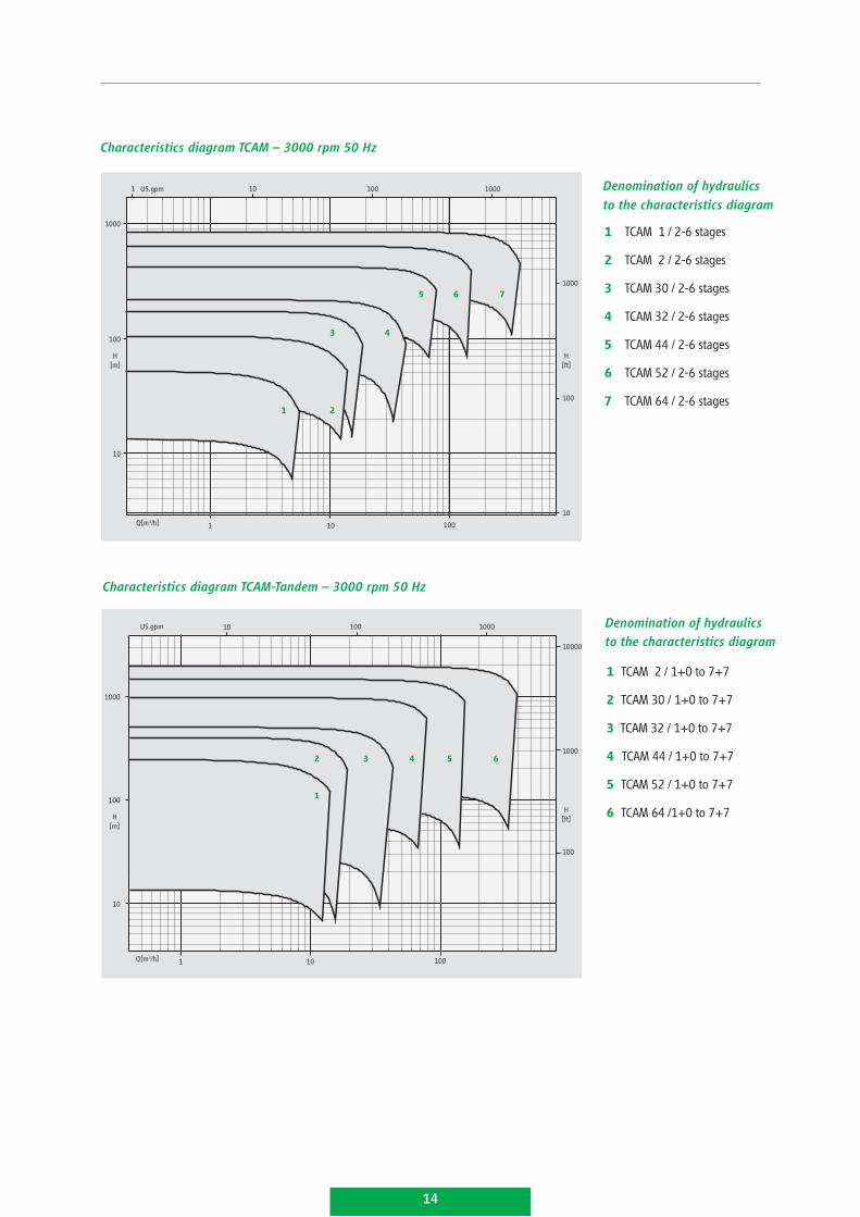
Characteristics diagram TCAM – 3000 rpm 50 Hz
1 TCAM 1 / 2-6 stages
2 TCAM 2 / 2-6 stages
3 TCAM 30 / 2-6 stages
4 TCAM 32 / 2-6 stages
5 TCAM 44 / 2-6 stages
6 TCAM 52 / 2-6 stages
7 TCAM 64 / 2-6 stages
Denomination of hydraulics
to the characteristics diagramUS.gpm
H[m]
H[ft]
10
10
1
1
100
100
1000
1000
1000
100
100
10
10
1
3 4
5
2
7 6
Q[m3/h]
Characteristics diagram TCAM-Tandem – 3000 rpm 50 Hz
1 TCAM 2 / 1+0 to 7+7
2 TCAM 30 / 1+0 to 7+7
3 TCAM 32 / 1+0 to 7+7
4 TCAM 44 / 1+0 to 7+7
5 TCAM 52 / 1+0 to 7+7
6 TCAM 64 /1+0 to 7+7
Denomination of hydraulics to the characteristics diagram
US.gpm
H[m]
H[ft]
10
101
100
100
1000
1000
10000
1000
100
100
10
Q[m3/h]
1
3 2 5 6 4
14
Denomination of hydraulics
to the characteristics diagram
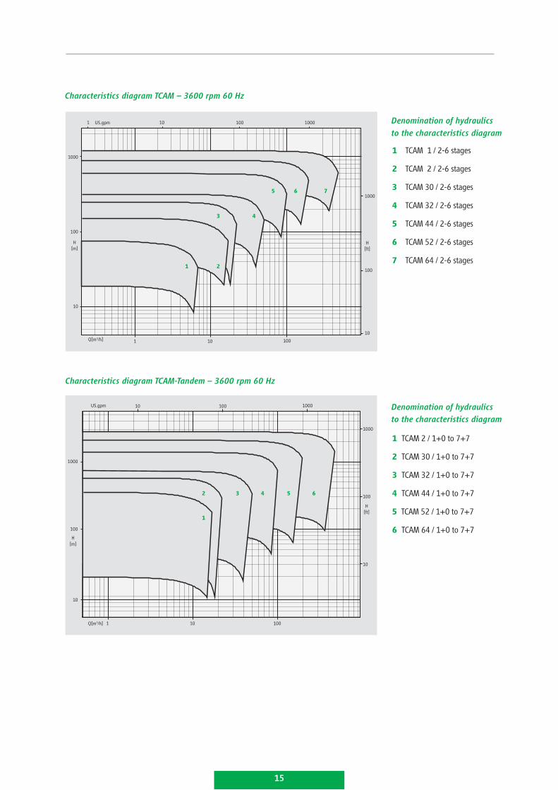
1 TCAM 1 / 2-6 stages
2 TCAM 2 / 2-6 stages
3 TCAM 30 / 2-6 stages
4 TCAM 32 / 2-6 stages
5 TCAM 44 / 2-6 stages
6 TCAM 52 / 2-6 stages
7 TCAM 64 / 2-6 stages
Denomination of hydraulics
to the characteristics diagram
Characteristics diagram TCAM – 3600 rpm 60 Hz
US.gpm
H[m]
H[ft]
10
10
1
1
100
100
1000
1000
1000
100
100
10
10
1
3 4
5
2
7 6
Q[m3/h]
Characteristics diagram TCAM-Tandem – 3600 rpm 60 Hz
1 TCAM 2 / 1+0 to 7+7
2 TCAM 30 / 1+0 to 7+7
3 TCAM 32 / 1+0 to 7+7
4 TCAM 44 / 1+0 to 7+7
5 TCAM 52 / 1+0 to 7+7
6 TCAM 64 / 1+0 to 7+7
Denomination of hydraulics to the characteristics diagram
H[ft]
US.gpm
H[m]
10
10
1
1000
100
1000
1000
100
100
10
10
Q[m3/h]
1
2 3 4 5 6
100
15
Our products comply with:
Explosion protection acc. to ■■
ATEX / UL / CQST / CSA
VOC directive 1999/13/EC■■
TA-Luft■■
IPPC directive■■
CE■■
RCCM, level 2■■
Rosgortechnazdor■■
HERMETIC-Pumpen GmbH is certified acc. to:
ISO 9001:2000■■
GOST “R”■■
ATEX 94/9/EC■■
AD HP 0 / TRD 201■■
DIN EN 729-2■■
KTA 1401, QSP 4a■■
Convincing service.
Important features are readiness, mobility, flexibility, availability and reliability.
We are anxious to ensure a pump operation at best availability and efficiency
to our customers.
Installation and commissioning
service effected on site by own ■■
service technicians
Spare part servicing
prompt and longstanding ■■
availability
customized assistance in spare ■■
part stockkeeping
Repair and overhauling
professional repairs including test ■■
run executed by the parent factory
or executed by one of our service ■■
stations worldwide
Maintenance and service
agreement
concepts individually worked ■■
out to increase the availability ■■
of your production facilities
Training and workshopsextra qualification of your ■■
staff to ensure the course of
your manufacture
HERMETIC-Pumpen GmbHGewerbestrasse 51 · D-79194 Gundelfingenphone +49-761-5830-0 · fax [email protected]://www.lederle-hermetic.com
PRODUKTINFOTCN-TCAM/E/02/2009


