62
SMC100CC & SMC100PP Single-Axis Motion Controller/Driver for DC or Stepper Motor LabVIEW Drivers Manual V2.0.x For Motion, Think Newport ™ For Motion, Think Newport ™
SMC100CC & SMC100PP
Single-Axis Motion Controller/Driver for DC or Stepper Motor
LabVIEW Drivers Manual
V2.0.x
For Motion, Think Newport™ For Motion, Think Newport™
SMC100CC & SMC100PP Single-Axis Motion Controller/Driver for DC or Stepper Motor
Preface
Confidentiality & Proprietary Rights
Reservation of Title
The Newport Programs and all materials furnished or produced in connection with them ("Related Materials") contain trade secrets of Newport and are for use only in the manner expressly permitted. Newport claims and reserves all rights and benefits afforded under law in the Programs provided by Newport Corporation.
Newport shall retain full ownership of Intellectual Property Rights in and to all development, process, align or assembly technologies developed and other derivative work that may be developed by Newport. Customer shall not challenge, or cause any third party to challenge, the rights of Newport.
Preservation of Secrecy and Confidentiality and Restrictions to Access
Customer shall protect the Newport Programs and Related Materials as trade secrets of Newport, and shall devote its best efforts to ensure that all its personnel protect the Newport Programs as trade secrets of Newport Corporation. Customer shall not at any time disclose Newport's trade secrets to any other person, firm, organization, or employee that does not need (consistent with Customer's right of use hereunder) to obtain access to the Newport Programs and Related Materials. These restrictions shall not apply to information (1) generally known to the public or obtainable from public sources; (2) readily apparent from the keyboard operations, visual display, or output reports of the Programs; (3) previously in the possession of Customer or subsequently developed or acquired without reliance on the Newport Programs; or (4) approved by Newport for release without restriction.
©2013 Newport Corporation 1791 Deere Ave. Irvine, CA 92606, USA (949) 863-3144
EDH0209En2020 – 04/13 ii
SMC100CC & SMC100PP Single-Axis Motion Controller/Driver for DC or Stepper Motor
Table of Contents
Preface ..............................................................................................................................ii
1.0 SMC100 Drivers ........................................................................................... 1
2.0 VIs Description ............................................................................................. 4 2.1 Serial Communication .............................................................................................................4
2.1.1 Port Init.vi ...........................................................................................................4
2.1.2 Read Write.vi.......................................................................................................4
2.1.3 Close.vi ................................................................................................................5
2.1.4 Get driver version.vi............................................................................................5
2.2 SMC Configuration .................................................................................................................5
2.2.1 Enter/Leave Configuration state.vi.......................................................................6
2.2.2 Get acceleration.vi................................................................................................6
2.2.3 Set acceleration.vi ................................................................................................7
2.2.4 Get backlash compensation.vi..............................................................................7
2.2.5 Set backlash compensation.vi ..............................................................................8
2.2.6 Get base velocity.vi..............................................................................................8
2.2.7 Set base velocity.vi ..............................................................................................9
2.2.8 Get controller's axis number.vi ............................................................................9
2.2.9 Set controller's axis number.vi ...........................................................................10
2.2.10 Get control loop state.vi ...................................................................................10
2.2.11 Set control loop state.vi....................................................................................11
2.2.12 Get cut off frequency.vi ...................................................................................11
2.2.13 Set cut off frequency.vi....................................................................................12
2.2.14 Get driver voltage.vi ........................................................................................12
2.2.15 Set driver voltage.vi .........................................................................................12
2.2.16 Get encoder increment.vi .................................................................................13
2.2.17 Set encoder increment.vi..................................................................................13
2.2.18 Get following error limit.vi..............................................................................13
2.2.19 Set following error limit.vi ..............................................................................14
2.2.20 Get friction compensation.vi............................................................................14
2.2.21 Set friction compensation.vi ............................................................................15
2.2.22 Get HOME high velocity.vi .............................................................................15
2.2.23 Set HOME high velocity.vi..............................................................................16
2.2.24 Get HOME time-out.vi ....................................................................................16
2.2.25 Set HOME time-out.vi .....................................................................................16
2.2.26 Get HOME type.vi ...........................................................................................17
2.2.27 Set HOME type.vi............................................................................................17
iii EDH0209En2020 – 04/13
SMC100CC & SMC100PP Single-Axis Motion Controller/Driver for DC or Stepper Motor
2.2.28 Get jerk time.vi ................................................................................................18
2.2.29 Set jerk time.vi .................................................................................................18
2.2.30 Get KD.vi.........................................................................................................18
2.2.31 Set KD.vi .........................................................................................................19
2.2.32 Get KI.vi ..........................................................................................................19
2.2.33 Set KI.vi ...........................................................................................................19
2.2.34 Get KP.vi .........................................................................................................20
2.2.35 Set KP.vi ..........................................................................................................20
2.2.36 Get motor's peak current limit.vi......................................................................20
2.2.37 Set motor's peak current limit.vi ......................................................................21
2.2.38 Get motor's rms current.vi................................................................................21
2.2.39 Set motor's rms current.vi ................................................................................21
2.2.40 Get motor's rms current average time.vi ..........................................................22
2.2.41 Set motor's rms current average time.vi...........................................................22
2.2.42 Get negative position limit.vi...........................................................................22
2.2.43 Set negative position limit.vi ...........................................................................23
2.2.44 Get positive position limit.vi............................................................................23
2.2.45 Set positive position limit.vi ............................................................................24
2.2.46 Get stage reference.vi.......................................................................................24
2.2.47 Set parameters from SmartStage.vi..................................................................25
2.2.48 Get stepper motor configuration (full step).vi..................................................25
2.2.49 Set stepper motor configuration (full step).vi ..................................................26
2.2.50 Get stepper motor configuration (micro-step factor).vi ...................................26
2.2.51 Set stepper motor configuration (micro-step factor).vi ....................................27
2.2.52 Get velocity.vi..................................................................................................27
2.2.53 Set velocity.vi ..................................................................................................28
2.2.54 Get velocity feed forward.vi ............................................................................28
2.2.55 Set velocity feed forward.vi .............................................................................29
2.2.56 Tell all configuration parameters.vi .................................................................29
2.2.57 Get stage identifier.vi.......................................................................................30
2.2.58 Set stage identifier.vi .......................................................................................30
2.2.59 Enable/disable keypad.vi .................................................................................31
2.3 Motion Setup .........................................................................................................................31
2.3.1 Enter/Leave disable state.vi ...............................................................................32
2.3.2 Get acceleration.vi .............................................................................................32
2.3.3 Set acceleration.vi ..............................................................................................33
2.3.4 Get cut off frequency.vi .....................................................................................33
2.3.5 Set cut off frequency.vi......................................................................................34
2.3.6 Get following error limit.vi................................................................................34
2.3.7 Set following error limit.vi ................................................................................35
2.3.8 Get friction compensation.vi..............................................................................35
2.3.9 Set friction compensation.vi ..............................................................................36
2.3.10 Get jerk time.vi ................................................................................................36
2.3.11 Set jerk time.vi .................................................................................................37
EDH0209En2020 – 04/13 iv
SMC100CC & SMC100PP Single-Axis Motion Controller/Driver for DC or Stepper Motor
2.3.12 Get KD.vi.........................................................................................................37
2.3.13 Set KD.vi .........................................................................................................38
2.3.14 Get KI.vi ..........................................................................................................38
2.3.15 Set KI.vi ...........................................................................................................38
2.3.16 Get KP.vi .........................................................................................................39
2.3.17 Set KP.vi ..........................................................................................................39
2.3.18 Get negative position limit.vi...........................................................................39
2.3.19 Set negative position limit.vi ...........................................................................40
2.3.20 Get positive position limit.vi............................................................................40
2.3.21 Set positive position limit.vi ............................................................................41
2.3.22 Get velocity.vi..................................................................................................41
2.3.23 Set velocity.vi ..................................................................................................42
2.3.24 Get velocity feed forward.vi ............................................................................42
2.3.25 Set velocity feed forward.vi .............................................................................43
2.4 Motion ...................................................................................................................................43
2.4.1 Home.vi .............................................................................................................43
2.4.2 Get absolute position.vi .....................................................................................44
2.4.3 Move absolute.vi................................................................................................44
2.4.4 Get target relative position.vi.............................................................................44
2.4.5 Move relative.vi .................................................................................................45
2.4.6 Record a new target position.vi..........................................................................45
2.4.7 Get target position recorded.vi...........................................................................45
2.4.8 Execute the move recorded.vi ............................................................................46
2.4.9 Stop.vi................................................................................................................46
2.4.10 Leave jogging state.vi ......................................................................................46
2.5 General...................................................................................................................................47
2.5.1 Reset.vi ..............................................................................................................47
2.5.2 Tell controller status.vi ......................................................................................48
2.5.3 Tell current position.vi.......................................................................................49
2.5.4 Tell error string.vi ..............................................................................................49
2.5.5 Tell last error.vi..................................................................................................50
2.5.6 Tell set point position.vi ....................................................................................50
2.5.7 Tell target position.vi .........................................................................................51
2.5.8 Tell time for a relative motion.vi .......................................................................51
2.5.9 Get version.vi.....................................................................................................51
2.6 GPIO......................................................................................................................................52
2.6.1 Tell analog input value.vi ..................................................................................52
2.6.2 Tell TTL inputs value.vi ....................................................................................52
2.6.3 Get TTL outputs value.vi ...................................................................................53
2.6.4 Set TTL outputs value.vi....................................................................................53
2.7 Examples ...............................................................................................................................54
2.7.1 Wait for stop 1 axis.vi........................................................................................54
2.7.2 Wait for stop 3 axis.vi........................................................................................54
v EDH0209En2020 – 04/13
SMC100CC & SMC100PP Single-Axis Motion Controller/Driver for DC or Stepper Motor
EDH0209En2020 – 04/13 vi
Service Form ........................................................................................................ 55
SMC100CC & SMC100PP Single-Axis Motion Controller/Driver for DC or Stepper Motor
SMC100 LabVIEW Drivers
1.0 SMC100 Drivers
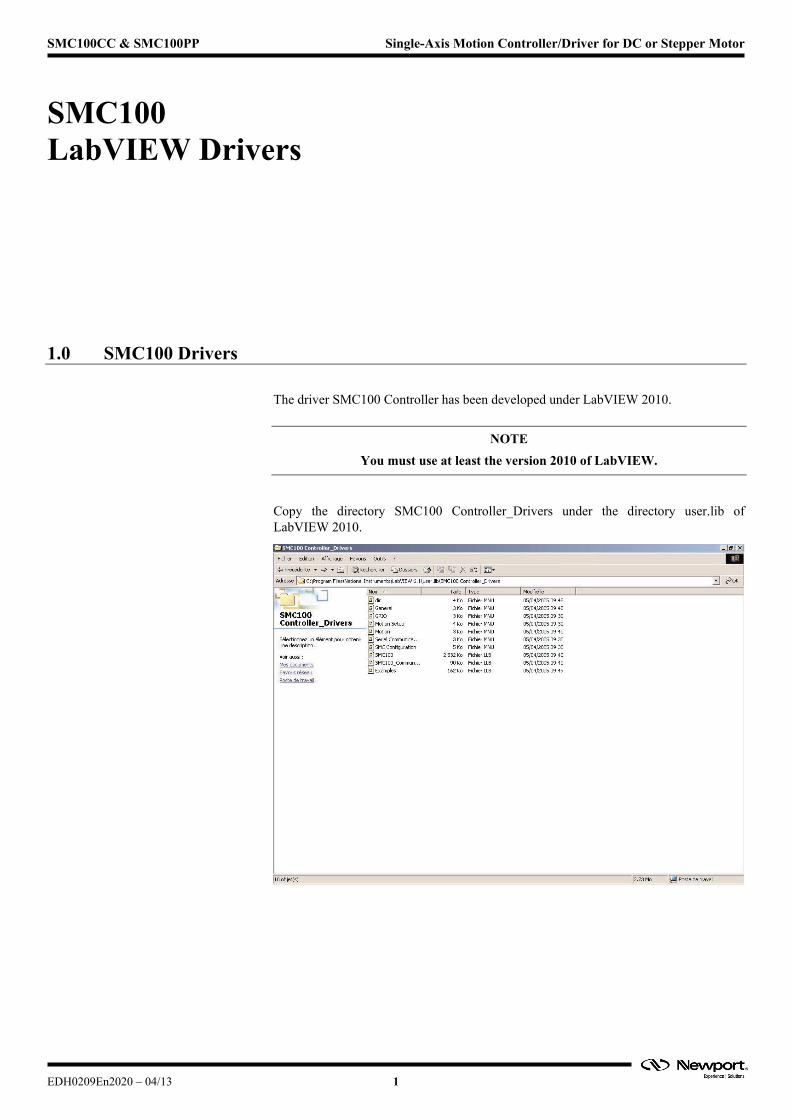
The driver SMC100 Controller has been developed under LabVIEW 2010.
NOTE
You must use at least the version 2010 of LabVIEW.
Copy the directory SMC100 Controller_Drivers under the directory user.lib of LabVIEW 2010.
EDH0209En2020 – 04/13 1
SMC100CC & SMC100PP Single-Axis Motion Controller/Driver for DC or Stepper Motor
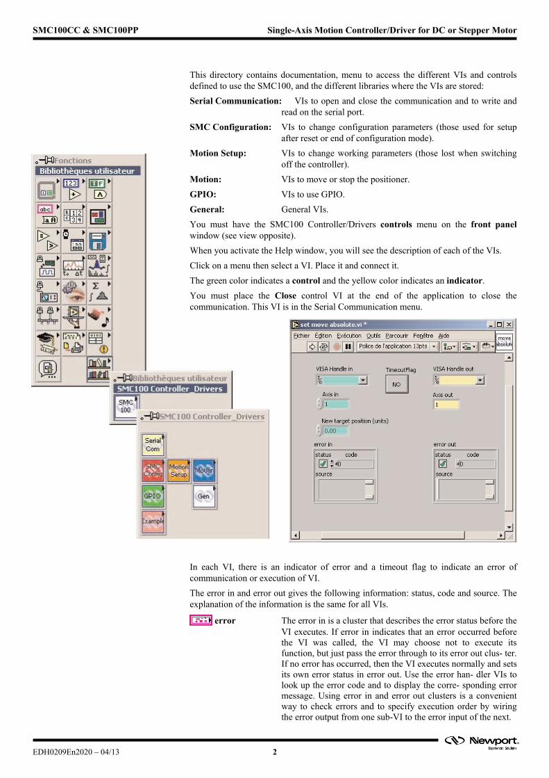
This directory contains documentation, menu to access the different VIs and controls defined to use the SMC100, and the different libraries where the VIs are stored:
Serial Communication: VIs to open and close the communication and to write and read on the serial port.
SMC Configuration: VIs to change configuration parameters (those used for setup after reset or end of configuration mode).
Motion Setup: VIs to change working parameters (those lost when switching off the controller).
Motion: VIs to move or stop the positioner.
GPIO: VIs to use GPIO.
General: General VIs.
You must have the SMC100 Controller/Drivers controls menu on the front panel window (see view opposite).
When you activate the Help window, you will see the description of each of the VIs.
Click on a menu then select a VI. Place it and connect it.
The green color indicates a control and the yellow color indicates an indicator.
You must place the Close control VI at the end of the application to close the communication. This VI is in the Serial Communication menu.
In each VI, there is an indicator of error and a timeout flag to indicate an error of communication or execution of VI.
The error in and error out gives the following information: status, code and source. The explanation of the information is the same for all VIs.
error The error in is a cluster that describes the error status before the VI executes. If error in indicates that an error occurred before the VI was called, the VI may choose not to execute its function, but just pass the error through to its error out clus- ter. If no error has occurred, then the VI executes normally and sets its own error status in error out. Use the error han- dler VIs to look up the error code and to display the corre- sponding error message. Using error in and error out clusters is a convenient way to check errors and to specify execution order by wiring the error output from one sub-VI to the error input of the next.
EDH0209En2020 – 04/13 2
SMC100CC & SMC100PP Single-Axis Motion Controller/Driver for DC or Stepper Motor
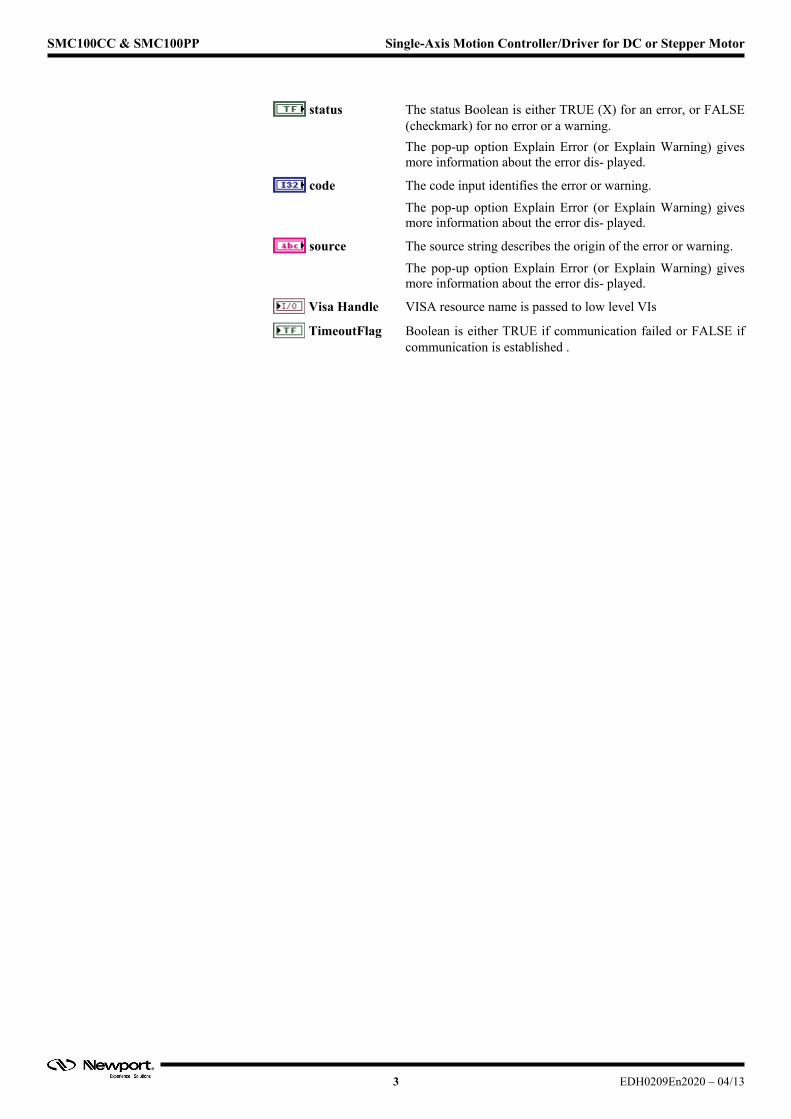
status The status Boolean is either TRUE (X) for an error, or FALSE (checkmark) for no error or a warning.
The pop-up option Explain Error (or Explain Warning) gives more information about the error dis- played.
code The code input identifies the error or warning.
The pop-up option Explain Error (or Explain Warning) gives more information about the error dis- played.
source The source string describes the origin of the error or warning.
The pop-up option Explain Error (or Explain Warning) gives more information about the error dis- played.
Visa Handle VISA resource name is passed to low level VIs
TimeoutFlag Boolean is either TRUE if communication failed or FALSE if communication is established .
3 EDH0209En2020 – 04/13
SMC100CC & SMC100PP Single-Axis Motion Controller/Driver for DC or Stepper Motor
2.0 VIs Description
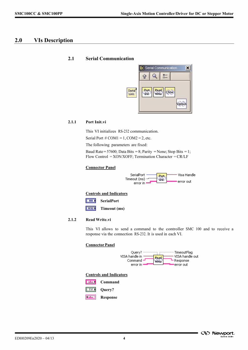
2.1 Serial Communication
2.1.1 Port Init.vi
This VI initializes RS-232 communication.
Serial Port # COM1 = 1, COM2 = 2, etc.
The following parameters are fixed:
Baud Rate = 57600; Data Bits = 8; Parity = None; Stop Bits = 1; Flow Control = XON/XOFF; Termination Character = CR/LF
Connector Panel
Controls and Indicators
SerialPort
Timeout (ms)
2.1.2 Read Write.vi
This VI allows to send a command to the controller SMC 100 and to receive a response via the connection RS-232. It is used in each VI.
Connector Panel
Controls and Indicators
Command
Query?
Response
EDH0209En2020 – 04/13 4

SMC100CC & SMC100PP Single-Axis Motion Controller/Driver for DC or Stepper Motor
2.1.3 Close.vi
This VI closes the opened serial port of communication.
Connector Panel
2.1.4 Get driver version.vi
This VI returns the SMC100 LabVIEW driver version.
Connector Panel
Controls and Indicators
Version
2.2 SMC Configuration
5 EDH0209En2020 – 04/13
SMC100CC & SMC100PP Single-Axis Motion Controller/Driver for DC or Stepper Motor
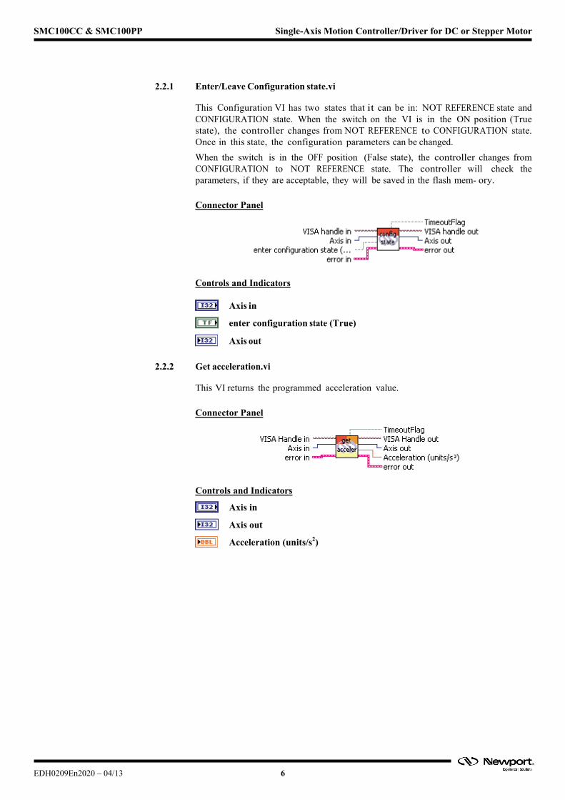
2.2.1 Enter/Leave Configuration state.vi
This Configuration VI has two states that it can be in: NOT REFERENCE state and CONFIGURATION state. When the switch on the VI is in the ON position (True state), the controller changes from NOT REFERENCE to CONFIGURATION state. Once in this state, the configuration parameters can be changed.
When the switch is in the OFF position (False state), the controller changes from CONFIGURATION to NOT REFERENCE state. The controller will check the parameters, if they are acceptable, they will be saved in the flash mem- ory.
Connector Panel
Controls and Indicators
Axis in
enter configuration state (True)
Axis out
2.2.2 Get acceleration.vi
This VI returns the programmed acceleration value.
Connector Panel
Controls and Indicators
Axis in
Axis out
Acceleration (units/s2)
EDH0209En2020 – 04/13 6
SMC100CC & SMC100PP Single-Axis Motion Controller/Driver for DC or Stepper Motor
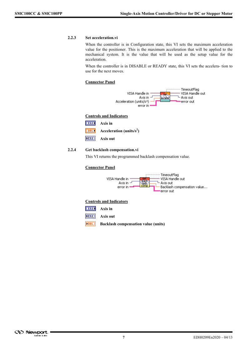
2.2.3 Set acceleration.vi
When the controller is in Configuration state, this VI sets the maximum acceleration value for the positioner. This is the maximum acceleration that will be applied to the mechanical system. It is the value that will be used as the setup value for the acceleration.
When the controller is in DISABLE or READY state, this VI sets the accelera- tion to use for the next moves.
Connector Panel
Controls and Indicators
Axis in
Acceleration (units/s2)
Axis out
2.2.4 Get backlash compensation.vi
This VI returns the programmed backlash compensation value.
Connector Panel
Controls and Indicators
Axis in
Axis out
Backlash compensation value (units)
7 EDH0209En2020 – 04/13
SMC100CC & SMC100PP Single-Axis Motion Controller/Driver for DC or Stepper Motor
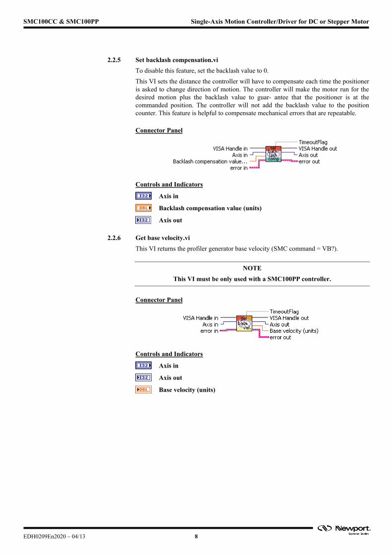
2.2.5 Set backlash compensation.vi
To disable this feature, set the backlash value to 0.
This VI sets the distance the controller will have to compensate each time the positioner is asked to change direction of motion. The controller will make the motor run for the desired motion plus the backlash value to guar- antee that the positioner is at the commanded position. The controller will not add the backlash value to the position counter. This feature is helpful to compensate mechanical errors that are repeatable.
Connector Panel
Controls and Indicators
Axis in
Backlash compensation value (units)
Axis out
2.2.6 Get base velocity.vi
This VI returns the profiler generator base velocity (SMC command = VB?).
NOTE
This VI must be only used with a SMC100PP controller.
Connector Panel
Controls and Indicators
Axis in
Axis out
Base velocity (units)
EDH0209En2020 – 04/13 8
SMC100CC & SMC100PP Single-Axis Motion Controller/Driver for DC or Stepper Motor
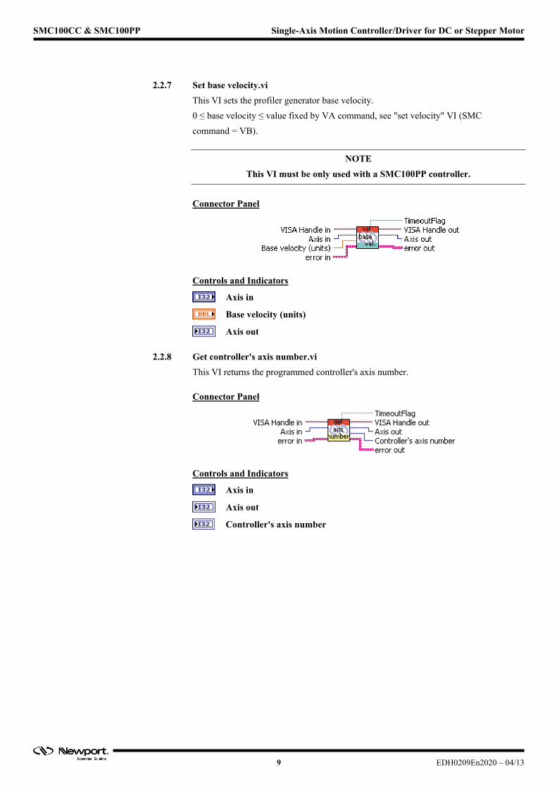
2.2.7 Set base velocity.vi
This VI sets the profiler generator base velocity.
0 ≤ base velocity ≤ value fixed by VA command, see "set velocity" VI (SMC
command = VB).
NOTE
This VI must be only used with a SMC100PP controller.
Connector Panel
Controls and Indicators
Axis in
Base velocity (units)
Axis out
2.2.8 Get controller's axis number.vi
This VI returns the programmed controller's axis number.
Connector Panel
Controls and Indicators
Axis in
Axis out
Controller's axis number
9 EDH0209En2020 – 04/13
SMC100CC & SMC100PP Single-Axis Motion Controller/Driver for DC or Stepper Motor
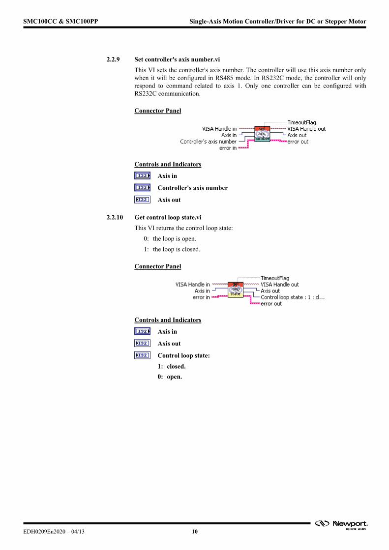
2.2.9 Set controller's axis number.vi
This VI sets the controller's axis number. The controller will use this axis number only when it will be configured in RS485 mode. In RS232C mode, the controller will only respond to command related to axis 1. Only one controller can be configured with RS232C communication.
Connector Panel
Controls and Indicators
Axis in
Controller's axis number
Axis out
2.2.10 Get control loop state.vi
This VI returns the control loop state:
0: the loop is open.
1: the loop is closed.
Connector Panel
Controls and Indicators
Axis in
Axis out
Control loop state:
1: closed.
0: open.
EDH0209En2020 – 04/13 10

SMC100CC & SMC100PP Single-Axis Motion Controller/Driver for DC or Stepper Motor
2.2.11 Set control loop state.vi
1 makes the controller to change the control loop from OPEN to CLOSED
state.
0 makes the controller to change the control loop from CLOSED to OPEN
state.
Connector Panel
Controls and Indicators
Axis in
Control loop state:
1: change to closed,
0: change to open,
Axis out
2.2.12 Get cut off frequency.vi
This VI returns the programmed low pass filter cut off frequency value for
Kd.
Connector Panel
Controls and Indicators
Axis in
Axis out
Cut off frequency value (Hertz)
11 EDH0209En2020 – 04/13
SMC100CC & SMC100PP Single-Axis Motion Controller/Driver for DC or Stepper Motor
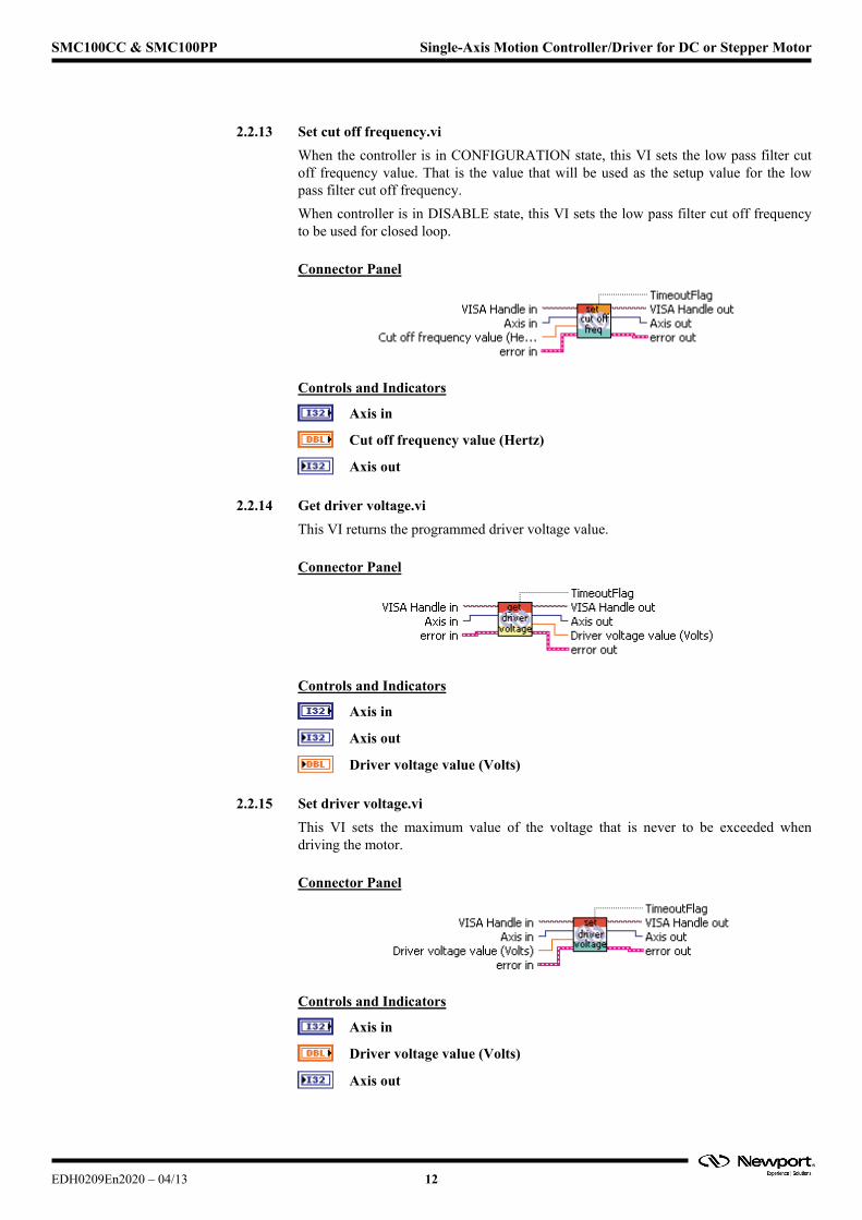
2.2.13 Set cut off frequency.vi
When the controller is in CONFIGURATION state, this VI sets the low pass filter cut off frequency value. That is the value that will be used as the setup value for the low pass filter cut off frequency.
When controller is in DISABLE state, this VI sets the low pass filter cut off frequency to be used for closed loop.
Connector Panel
Controls and Indicators
Axis in
Cut off frequency value (Hertz)
Axis out
2.2.14 Get driver voltage.vi
This VI returns the programmed driver voltage value.
Connector Panel
Controls and Indicators
Axis in
Axis out
Driver voltage value (Volts)
2.2.15 Set driver voltage.vi
This VI sets the maximum value of the voltage that is never to be exceeded when driving the motor.
Connector Panel
Controls and Indicators
Axis in
Driver voltage value (Volts)
Axis out
EDH0209En2020 – 04/13 12
SMC100CC & SMC100PP Single-Axis Motion Controller/Driver for DC or Stepper Motor
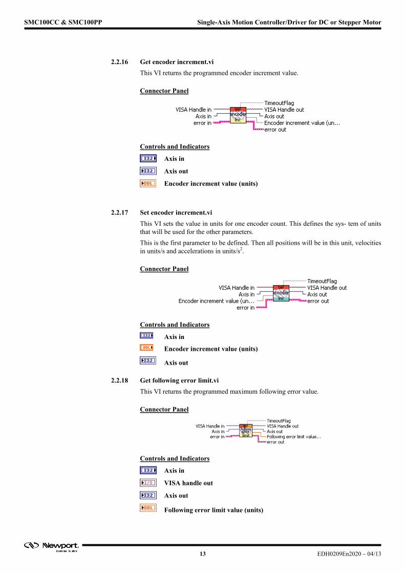
2.2.16 Get encoder increment.vi
This VI returns the programmed encoder increment value.
Connector Panel
Controls and Indicators
Axis in
Axis out
Encoder increment value (units)
2.2.17 Set encoder increment.vi
This VI sets the value in units for one encoder count. This defines the sys- tem of units that will be used for the other parameters.
This is the first parameter to be defined. Then all positions will be in this unit, velocities in units/s and accelerations in units/s2.
Connector Panel
Controls and Indicators
Axis in
Encoder increment value (units)
Axis out
2.2.18 Get following error limit.vi
This VI returns the programmed maximum following error value.
Connector Panel
Controls and Indicators
Axis in
VISA handle out
Axis out
Following error limit value (units)
13 EDH0209En2020 – 04/13
SMC100CC & SMC100PP Single-Axis Motion Controller/Driver for DC or Stepper Motor
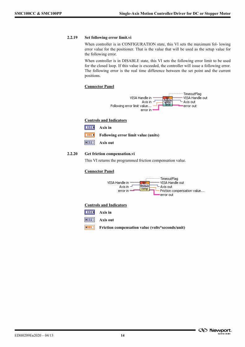
2.2.19 Set following error limit.vi
When controller is in CONFIGURATION state, this VI sets the maximum fol- lowing error value for the positioner. That is the value that will be used as the setup value for the following error.
When controller is in DISABLE state, this VI sets the following error limit to be used for the closed loop. If this value is exceeded, the controller will issue a following error. The following error is the real time difference between the set point and the current positions.
Connector Panel
Controls and Indicators
Axis in
Following error limit value (units)
Axis out
2.2.20 Get friction compensation.vi
This VI returns the programmed friction compensation value.
Connector Panel
Controls and Indicators
Axis in
Axis out
Friction compensation value (volts*seconds/unit)
EDH0209En2020 – 04/13 14
SMC100CC & SMC100PP Single-Axis Motion Controller/Driver for DC or Stepper Motor
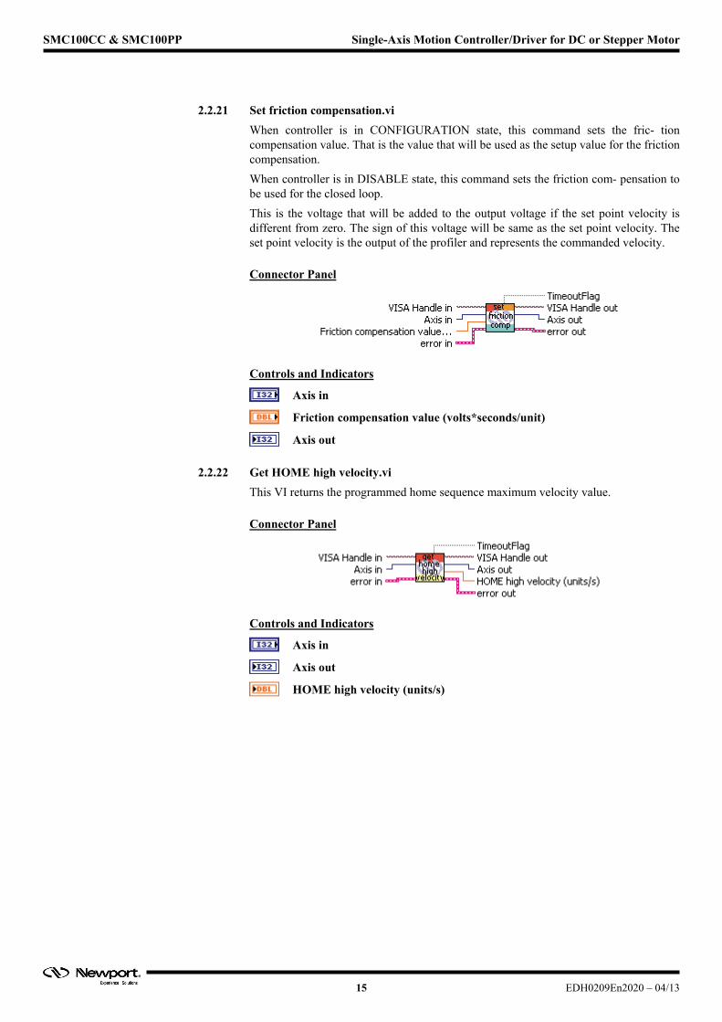
2.2.21 Set friction compensation.vi
When controller is in CONFIGURATION state, this command sets the fric- tion compensation value. That is the value that will be used as the setup value for the friction compensation.
When controller is in DISABLE state, this command sets the friction com- pensation to be used for the closed loop.
This is the voltage that will be added to the output voltage if the set point velocity is different from zero. The sign of this voltage will be same as the set point velocity. The set point velocity is the output of the profiler and represents the commanded velocity.
Connector Panel
Controls and Indicators
Axis in
Friction compensation value (volts*seconds/unit)
Axis out
2.2.22 Get HOME high velocity.vi
This VI returns the programmed home sequence maximum velocity value.
Connector Panel
Controls and Indicators
Axis in
Axis out
HOME high velocity (units/s)
15 EDH0209En2020 – 04/13
SMC100CC & SMC100PP Single-Axis Motion Controller/Driver for DC or Stepper Motor
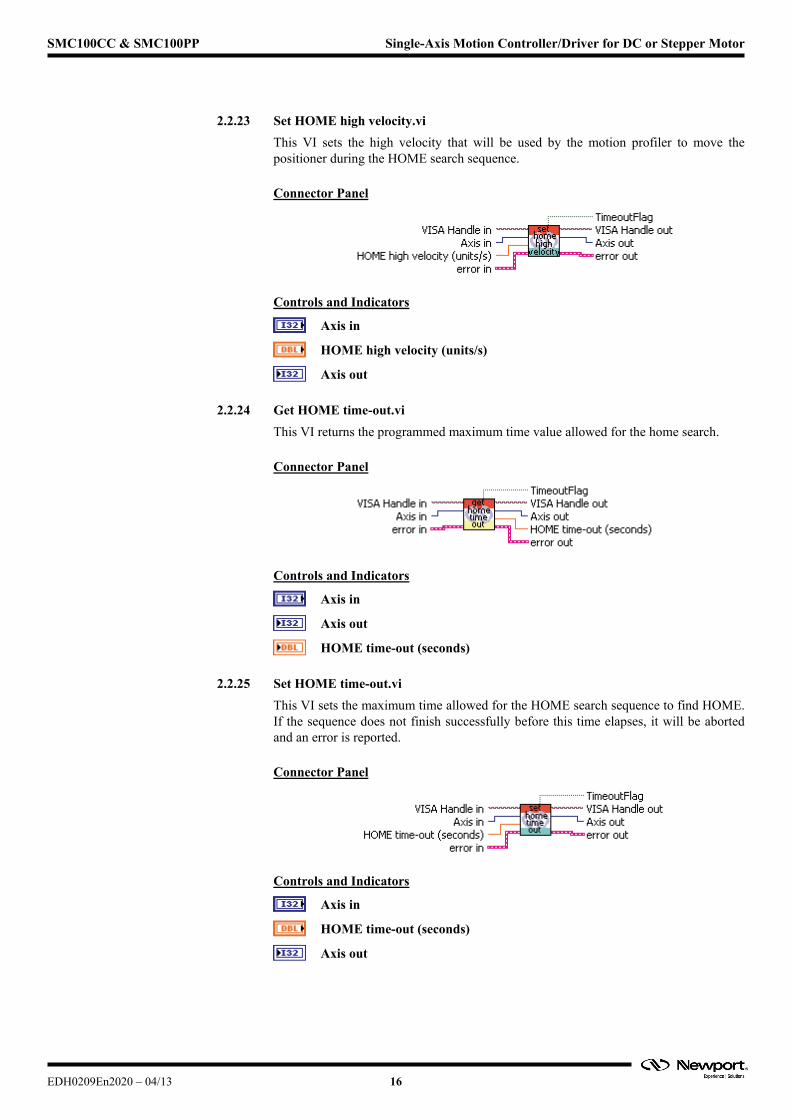
2.2.23 Set HOME high velocity.vi
This VI sets the high velocity that will be used by the motion profiler to move the positioner during the HOME search sequence.
Connector Panel
Controls and Indicators
Axis in
HOME high velocity (units/s)
Axis out
2.2.24 Get HOME time-out.vi
This VI returns the programmed maximum time value allowed for the home search.
Connector Panel
Controls and Indicators
Axis in
Axis out
HOME time-out (seconds)
2.2.25 Set HOME time-out.vi
This VI sets the maximum time allowed for the HOME search sequence to find HOME. If the sequence does not finish successfully before this time elapses, it will be aborted and an error is reported.
Connector Panel
Controls and Indicators
Axis in
HOME time-out (seconds)
Axis out
EDH0209En2020 – 04/13 16

17 EDH0209En2020 – 04/13
SMC100CC & SMC100PP Single-Axis Motion Controller/Driver for DC or Stepper Motor
2.2.26 Get HOME type.vi
This VI returns the programmed home type:
0: use MZ (Home) switch and encoder Index.
1: use current position as home.
2: use MZ (Home) switch only.
3: use EoR(Neg. Limit) switch and encoder Index.
4: use EoR(Neg. Limit) switch only.
Connector Panel
Controls and Indicators
Axis in
Axis out
Home type:
0: use MZ switch and encoder Index.
1: use current position as HOME.
2: use MZ switch only.
3: use EoR- switch and encoder Index.
4: use EoR- switch only.
2.2.27 Set HOME type.vi
This VI sets the HOME type that will be used when the HOME command is executed.
0: use MZ (Home) switch and encoder Index.
1: use current position as home.
2: use MZ (Home) switch only.
3: use EoR (Neg. Limit) switch and encoder Index.
4: use EoR (Neg. Limit) switch only.
Connector Panel
Controls and Indicators
Axis in
Home type value:
0: use MZ switch and encoder Index.
1: use current position as HOME.
2: use MZ switch only.
3: use EoR- switch and encoder Index.
4: use EoR- switch only.
Axis out
EDH0209En2020 – 04/13 18
SMC100CC & SMC100PP Single-Axis Motion Controller/Driver for DC or Stepper Motor
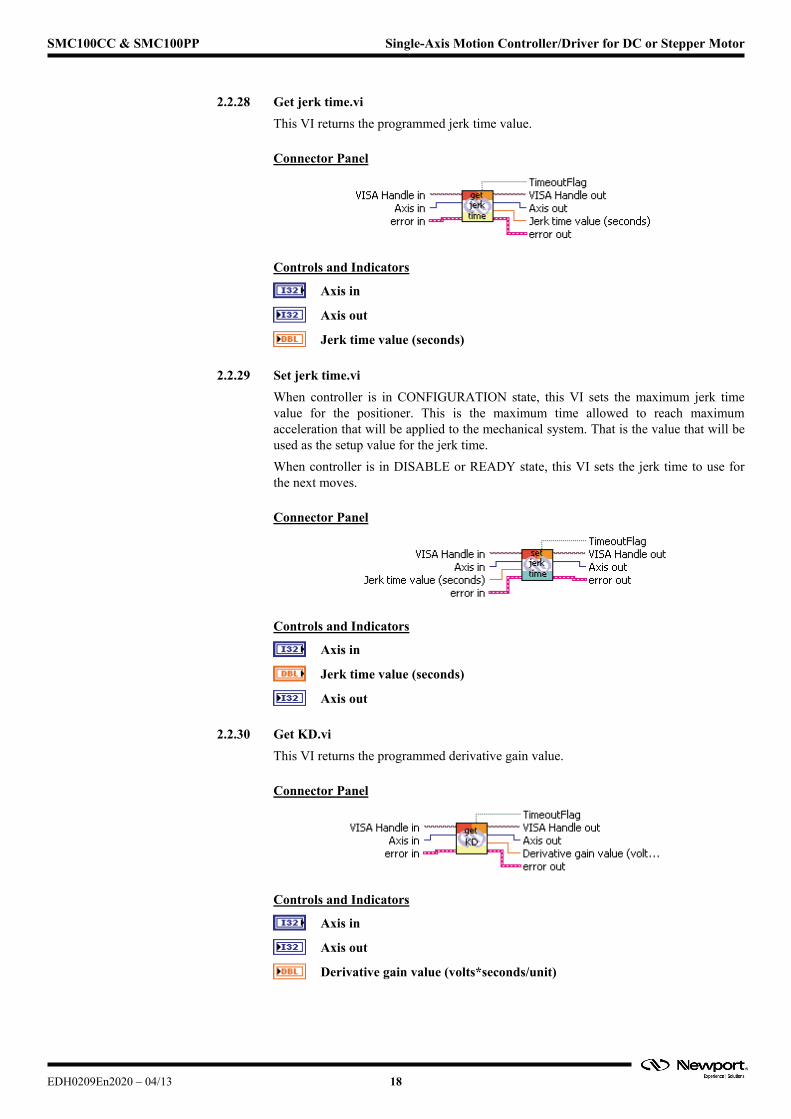
2.2.28 Get je
This VI returns the programmed jerk time value.
rk time.vi
Connector Panel
Controls and Indicators
Axis in
Axis out
Jerk time value (seconds)
2.2.29 Set je
When controller is in CONFIGURATION state, this VI sets the maximum jerk time sitioner. This is the maximum time allowed to reach maximum
l
rk time.vi
value for the poacceleration that will be applied to the mechanical system. That is the value that will be used as the setup value for the jerk time.
When controller is in DISABLE or READY state, this VI sets the jerk time to use for the next moves.
Connector Pane
Controls and Indicators
Axis in
Jerk time value (seconds)
Axis out
2.2.30 Get K
This VI returns the programmed derivative gain value.
D.vi
Connector Panel
Controls and Indicators
Axis in
Axis out
Derivative gain value (volts*seconds/unit)
SMC100CC & SMC100PP Single-Axis Motion Controller/Driver for DC or Stepper Motor
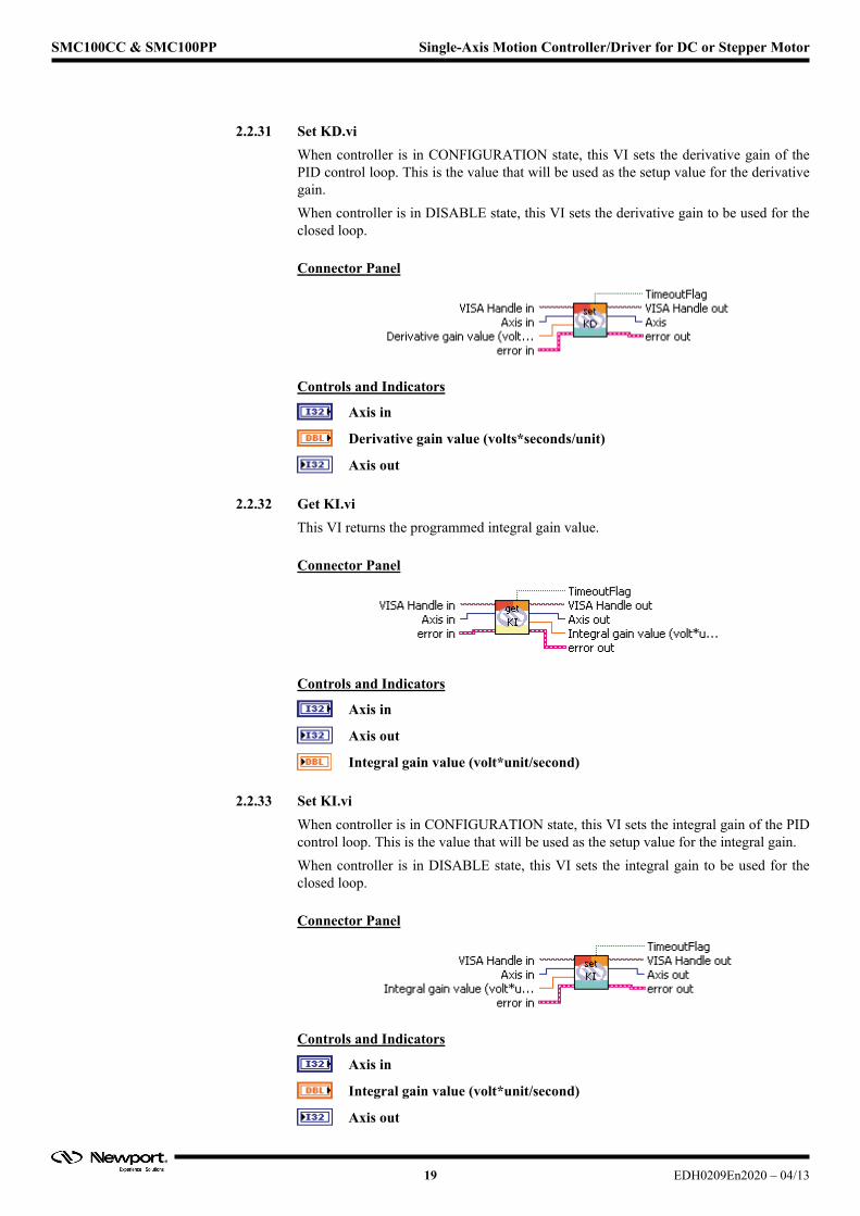
2.2.31 Set KD.vi
When controller is in CONFIGURATION state, this VI sets the derivative gain of the PID control loop. This is the value that will be used as the setup value for the derivative gain.
When controller is in DISABLE state, this VI sets the derivative gain to be used for the closed loop.
Connector Panel
Controls and Indicators
Axis in
Derivative gain value (volts*seconds/unit)
Axis out
2.2.32 Get KI.vi
This VI returns the programmed integral gain value.
Connector Panel
Controls and Indicators
Axis in
Axis out
Integral gain value (volt*unit/second)
2.2.33 Set KI.vi
When controller is in CONFIGURATION state, this VI sets the integral gain of the PID control loop. This is the value that will be used as the setup value for the integral gain.
When controller is in DISABLE state, this VI sets the integral gain to be used for the closed loop.
Connector Panel
Controls and Indicators
Axis in
Integral gain value (volt*unit/second)
Axis out
19 EDH0209En2020 – 04/13
SMC100CC & SMC100PP Single-Axis Motion Controller/Driver for DC or Stepper Motor
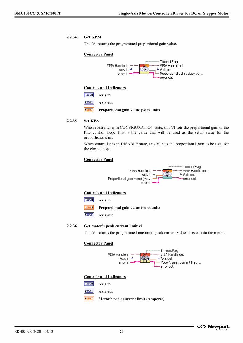
2.2.34 Get KP.vi
This VI returns the programmed proportional gain value.
Connector Panel
Controls and Indicators
Axis in
Axis out
Proportional gain value (volts/unit)
2.2.35 Set KP.vi
When controller is in CONFIGURATION state, this VI sets the proportional gain of the PID control loop. This is the value that will be used as the setup value for the proportional gain.
When controller is in DISABLE state, this VI sets the proportional gain to be used for the closed loop.
Connector Panel
Controls and Indicators
Axis in
Proportional gain value (volts/unit)
Axis out
2.2.36 Get motor's peak current limit.vi
This VI returns the programmed maximum peak current value allowed into the motor.
Connector Panel
Controls and Indicators
Axis in
Axis out
Motor's peak current limit (Amperes)
EDH0209En2020 – 04/13 20
SMC100CC & SMC100PP Single-Axis Motion Controller/Driver for DC or Stepper Motor
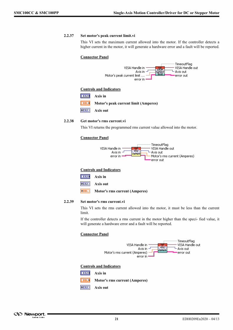
2.2.37 Set motor's peak current limit.vi
This VI sets the maximum current allowed into the motor. If the controller detects a higher current in the motor, it will generate a hardware error and a fault will be reported.
Connector Panel
Controls and Indicators
Axis in
Motor's peak current limit (Amperes)
Axis out
2.2.38 Get motor's rms current.vi
This VI returns the programmed rms current value allowed into the motor.
Connector Panel
Controls and Indicators
Axis in
Axis out
Motor's rms current (Amperes)
2.2.39 Set motor's rms current.vi
This VI sets the rms current allowed into the motor, it must be less than the current limit.
If the controller detects a rms current in the motor higher than the speci- fied value, it will generate a hardware error and a fault will be reported.
Connector Panel
Controls and Indicators
Axis in
Motor's rms current (Amperes)
Axis out
21 EDH0209En2020 – 04/13

SMC100CC & SMC100PP Single-Axis Motion Controller/Driver for DC or Stepper Motor
2.2.40 Get motor's rms current average time.vi
This VI returns the programmed average period value for the calculation of the rms current.
Connector Panel
Controls and Indicators
Axis in
Axis out
Motor's rms current average time (seconds)
2.2.41 Set motor's rms current average time.vi
This VI sets the averaging period for the calculation of the rms current.
Connector Panel
Controls and Indicators
Axis in
Motor's rms current average time (seconds)
Axis out
2.2.42 Get negative position limit.vi
This VI returns the programmed negative software position limit value for the positioner.
Connector Panel
Controls and Indicators
Axis in
Axis out
Negative software position limit (units)
EDH0209En2020 – 04/13 22
SMC100CC & SMC100PP Single-Axis Motion Controller/Driver for DC or Stepper Motor
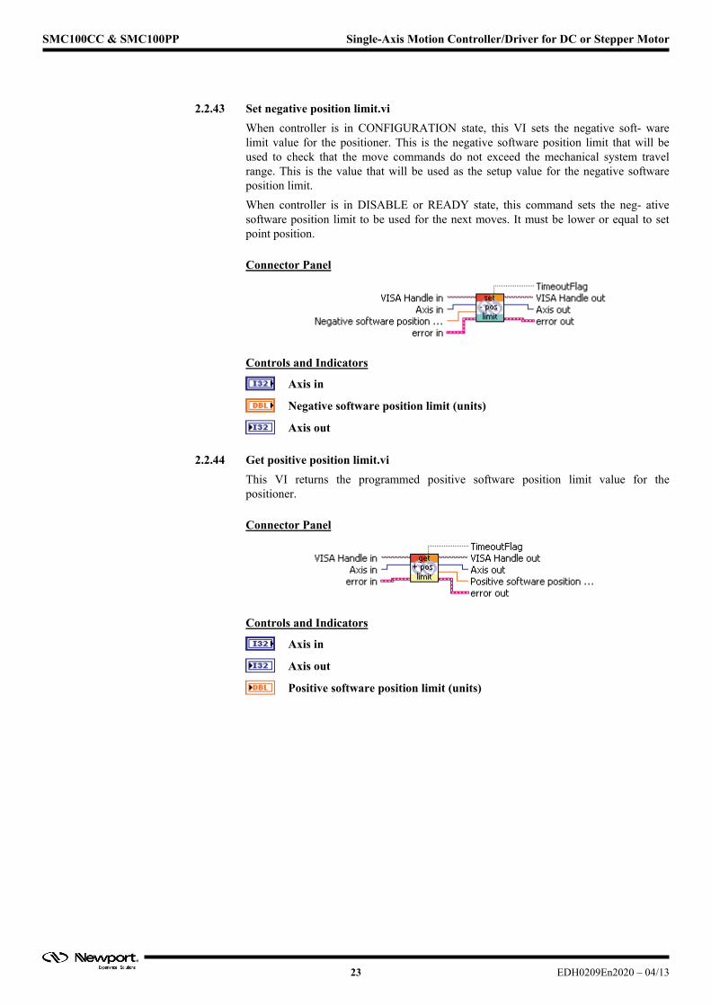
2.2.43 Set negative position limit.vi
When controller is in CONFIGURATION state, this VI sets the negative soft- ware limit value for the positioner. This is the negative software position limit that will be used to check that the move commands do not exceed the mechanical system travel range. This is the value that will be used as the setup value for the negative software position limit.
When controller is in DISABLE or READY state, this command sets the neg- ative software position limit to be used for the next moves. It must be lower or equal to set point position.
Connector Panel
Controls and Indicators
Axis in
Negative software position limit (units)
Axis out
2.2.44 Get positive position limit.vi
This VI returns the programmed positive software position limit value for the positioner.
Connector Panel
Controls and Indicators
Axis in
Axis out
Positive software position limit (units)
23 EDH0209En2020 – 04/13
SMC100CC & SMC100PP Single-Axis Motion Controller/Driver for DC or Stepper Motor
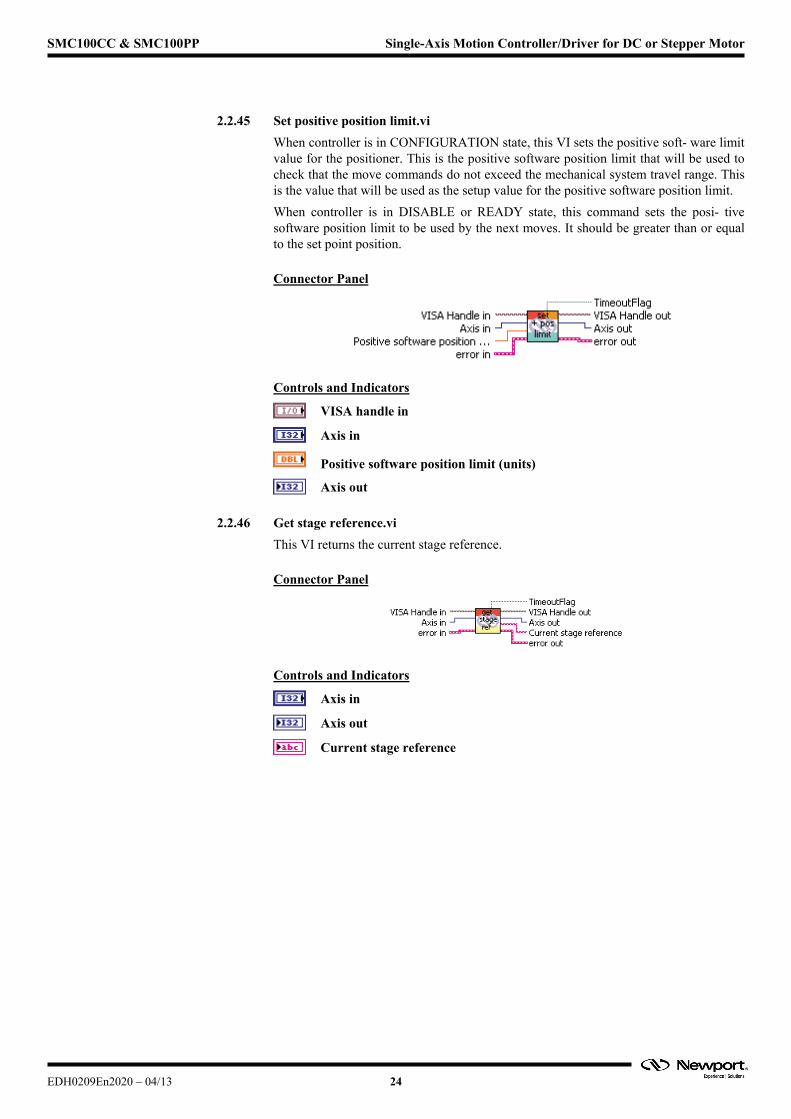
2.2.45 Set positive position limit.vi
When controller is in CONFIGURATION state, this VI sets the positive soft- ware limit value for the positioner. This is the positive software position limit that will be used to check that the move commands do not exceed the mechanical system travel range. This is the value that will be used as the setup value for the positive software position limit.
When controller is in DISABLE or READY state, this command sets the posi- tive software position limit to be used by the next moves. It should be greater than or equal to the set point position.
Connector Panel
Controls and Indicators
VISA handle in
Axis in
Positive software position limit (units)
Axis out
2.2.46 Get stage reference.vi
This VI returns the current stage reference.
Connector Panel
Controls and Indicators
Axis in
Axis out
Current stage reference
EDH0209En2020 – 04/13 24
SMC100CC & SMC100PP Single-Axis Motion Controller/Driver for DC or Stepper Motor
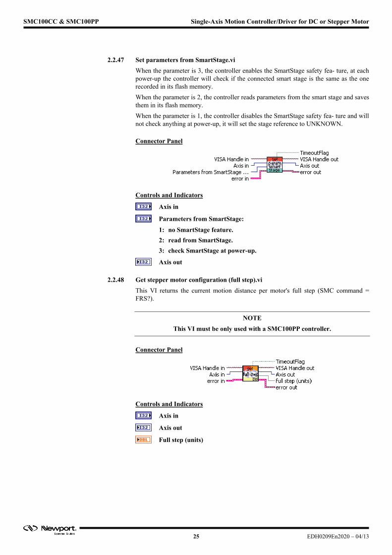
2.2.47 Set parameters from SmartStage.vi
When the parameter is 3, the controller enables the SmartStage safety fea- ture, at each power-up the controller will check if the connected smart stage is the same as the one recorded in its flash memory.
When the parameter is 2, the controller reads parameters from the smart stage and saves them in its flash memory.
When the parameter is 1, the controller disables the SmartStage safety fea- ture and will not check anything at power-up, it will set the stage reference to UNKNOWN.
Connector Panel
Controls and Indicators
Axis in
Parameters from SmartStage:
1: no SmartStage feature.
2: read from SmartStage.
3: check SmartStage at power-up.
Axis out
2.2.48 Get stepper motor configuration (full step).vi
This VI returns the current motion distance per motor's full step (SMC command = FRS?).
NOTE
This VI must be only used with a SMC100PP controller.
Connector Panel
Controls and Indicators
Axis in
Axis out
Full step (units)
25 EDH0209En2020 – 04/13
SMC100CC & SMC100PP Single-Axis Motion Controller/Driver for DC or Stepper Motor
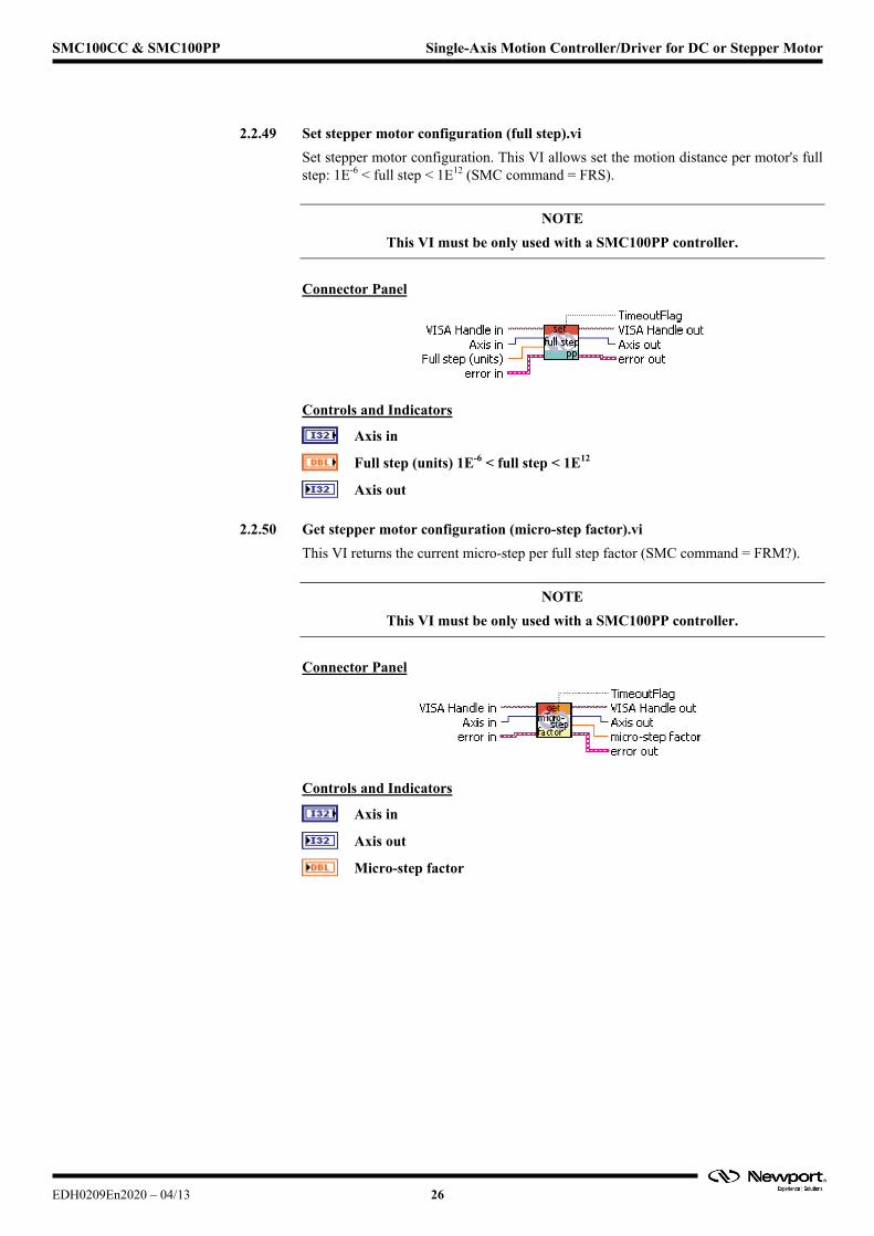
2.2.49 Set stepper motor configuration (full step).vi
Set stepper motor configuration. This VI allows set the motion distance per motor's full step: 1E-6 < full step < 1E12 (SMC command = FRS).
NOTE
This VI must be only used with a SMC100PP controller.
Connector Panel
Controls and Indicators
Axis in
Full step (units) 1E-6 < full step < 1E12
Axis out
2.2.50 Get stepper motor configuration (micro-step factor).vi
This VI returns the current micro-step per full step factor (SMC command = FRM?).
NOTE
This VI must be only used with a SMC100PP controller.
Connector Panel
Controls and Indicators
Axis in
Axis out
Micro-step factor
EDH0209En2020 – 04/13 26
SMC100CC & SMC100PP Single-Axis Motion Controller/Driver for DC or Stepper Motor
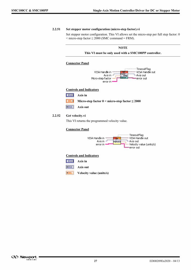
2.2.51 Set stepper motor configuration (micro-step factor).vi
Set stepper motor configuration. This VI allows set the micro-step per full step factor: 0 < micro-step factor ≤ 2000 (SMC command = FRM).
NOTE
This VI must be only used with a SMC100PP controller.
Connector Panel
Controls and Indicators
Axis in
Micro-step factor 0 < micro-step factor ≤ 2000
Axis out
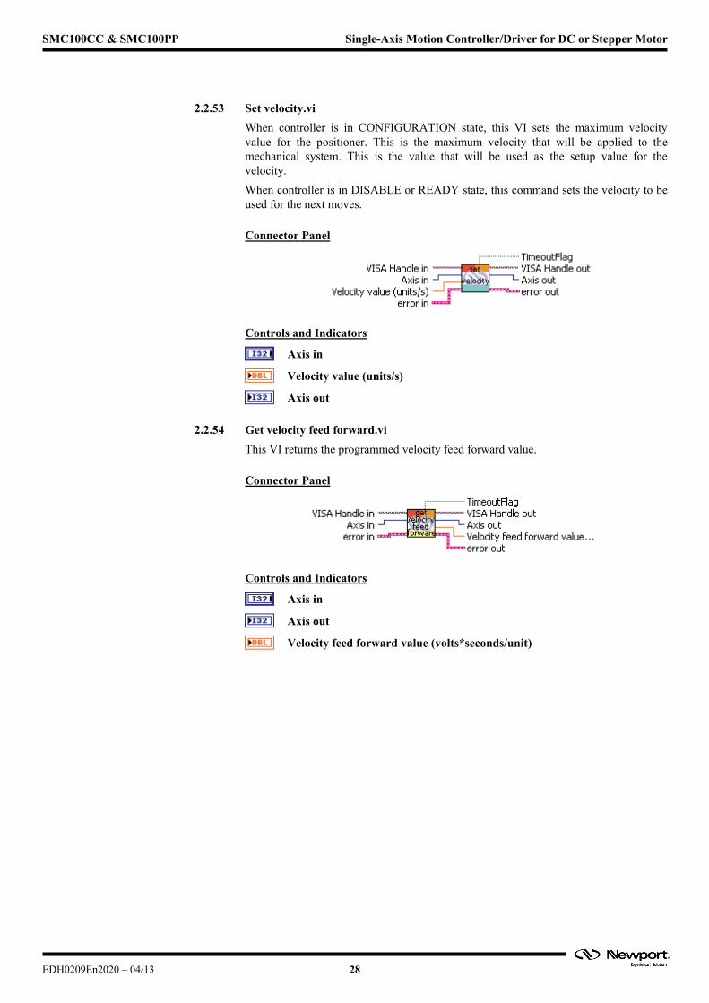
2.2.52 Get velocity.vi
This VI returns the programmed velocity value.
Connector Panel
Controls and Indicators
Axis in
Axis out
Velocity value (units/s)
27 EDH0209En2020 – 04/13
SMC100CC & SMC100PP Single-Axis Motion Controller/Driver for DC or Stepper Motor
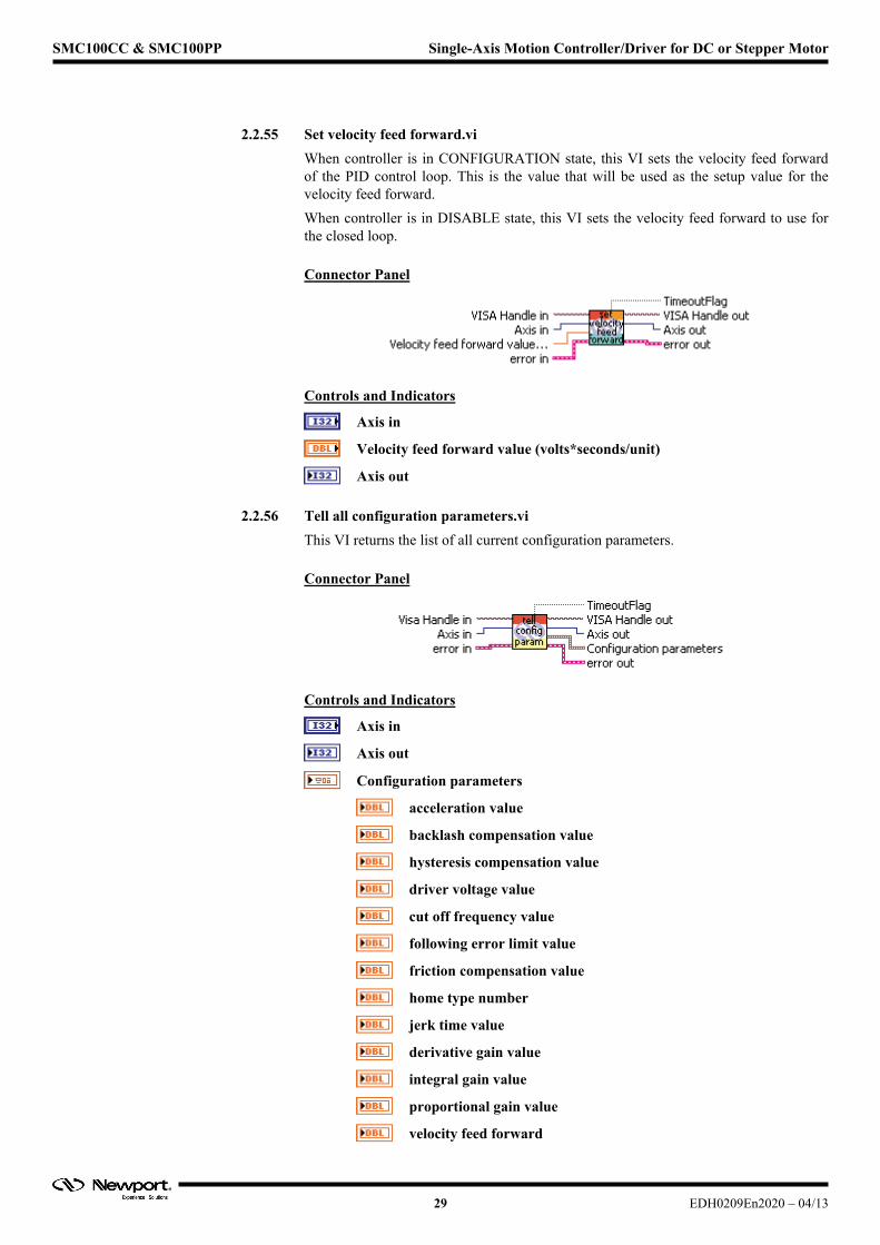
2.2.53 Set velocity.vi
When controller is in CONFIGURATION state, this VI sets the maximum velocity value for the positioner. This is the maximum velocity that will be applied to the mechanical system. This is the value that will be used as the setup value for the velocity.
When controller is in DISABLE or READY state, this command sets the velocity to be used for the next moves.
Connector Panel
Controls and Indicators
Axis in
Velocity value (units/s)
Axis out
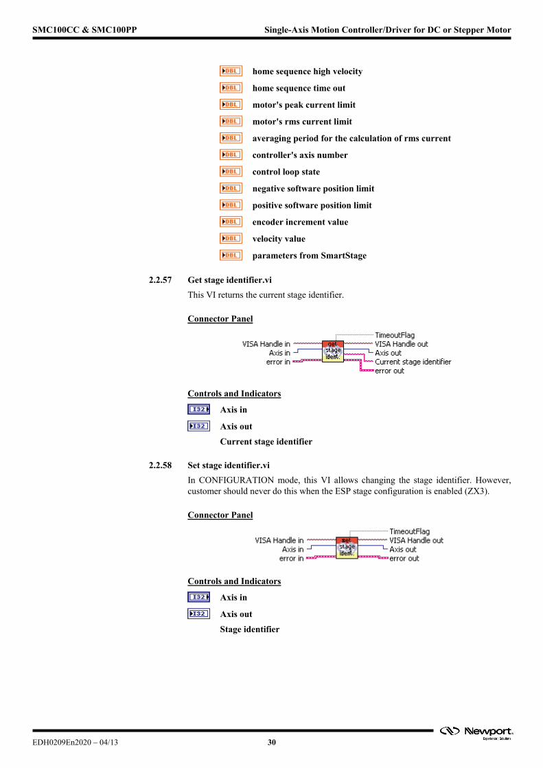
2.2.54 Get velocity feed forward.vi
This VI returns the programmed velocity feed forward value.
Connector Panel
Controls and Indicators
Axis in
Axis out
Velocity feed forward value (volts*seconds/unit)
EDH0209En2020 – 04/13 28
SMC100CC & SMC100PP Single-Axis Motion Controller/Driver for DC or Stepper Motor
2.2.55 Set velocity feed forward.vi
When controller is in CONFIGURATION state, this VI sets the velocity feed forward of the PID control loop. This is the value that will be used as the setup value for the velocity feed forward.
When controller is in DISABLE state, this VI sets the velocity feed forward to use for the closed loop.
Connector Panel
Controls and Indicators
Axis in
Velocity feed forward value (volts*seconds/unit)
Axis out
2.2.56 Tell all configuration parameters.vi
This VI returns the list of all current configuration parameters.
Connector Panel
Controls and Indicators
Axis in
Axis out
Configuration parameters
acceleration value
backlash compensation value
hysteresis compensation value
driver voltage value
cut off frequency value
following error limit value
friction compensation value
home type number
jerk time value
derivative gain value
integral gain value
proportional gain value
velocity feed forward
29 EDH0209En2020 – 04/13
SMC100CC & SMC100PP Single-Axis Motion Controller/Driver for DC or Stepper Motor
home sequence high velocity
home sequence time out
motor's peak current limit
motor's rms current limit
averaging period for the calculation of rms current
controller's axis number
control loop state
negative software position limit
positive software position limit
encoder increment value
velocity value
parameters from SmartStage
2.2.57 Get stage identifier.vi
This VI returns the current stage identifier.
Connector Panel
Controls and Indicators
Axis in
Axis out
Current stage identifier
2.2.58 Set stage identifier.vi
In CONFIGURATION mode, this VI allows changing the stage identifier. However, customer should never do this when the ESP stage configuration is enabled (ZX3).
Connector Panel
Controls and Indicators
Axis in
Axis out
Stage identifier
EDH0209En2020 – 04/13 30
SMC100CC & SMC100PP Single-Axis Motion Controller/Driver for DC or Stepper Motor
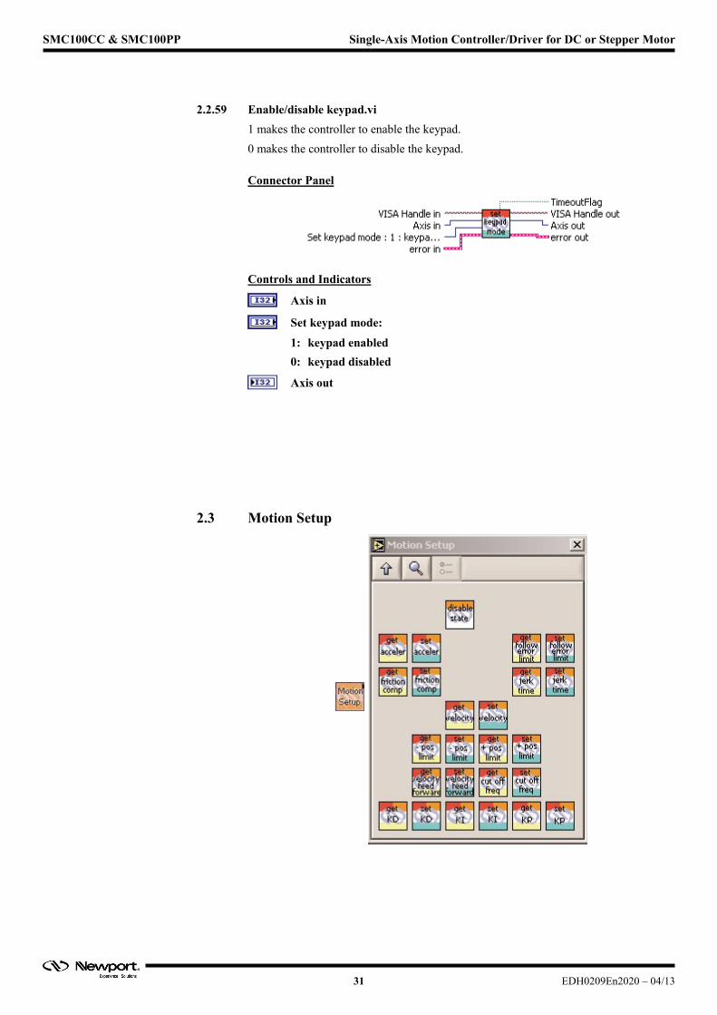
2.2.59 Enable/disable keypad.vi
1 makes the controller to enable the keypad.
0 makes the controller to disable the keypad.
Connector Panel
Controls and Indicators
Axis in
Set keypad mode:
1: keypad enabled
0: keypad disabled
Axis out
2.3 Motion Setup
31 EDH0209En2020 – 04/13

SMC100CC & SMC100PP Single-Axis Motion Controller/Driver for DC or Stepper Motor
2.3.1 Enter/Leave disable state.vi
When the VI switch is in the ON position (True state), the controller changes from READY to DISABLE state. The controller will open the control loop and de-energize the motor.
When the VI switch is in the OFF position, the controller changes from DIS- ABLE to READY state. The controller will set the set point position equal to the current position, clean-up the PID, energize the motor and close the control loop.
Connector Panel
Controls and Indicators
Enter disable state (True)
Axis in
Axis out
2.3.2 Get acceleration.vi
This VI returns the programmed acceleration value.
Connector Panel
Controls and Indicators
Axis in
Axis out
Acceleration (units/s2)
EDH0209En2020 – 04/13 32
SMC100CC & SMC100PP Single-Axis Motion Controller/Driver for DC or Stepper Motor
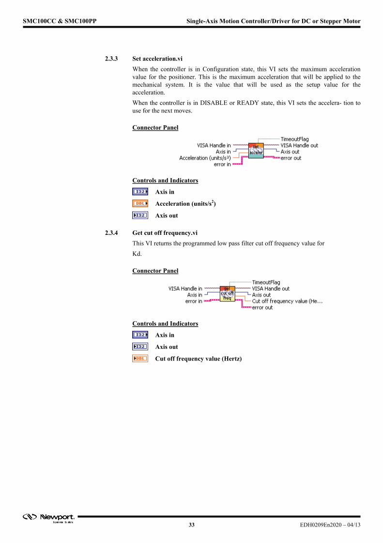
2.3.3 Set acceleration.vi
When the controller is in Configuration state, this VI sets the maximum acceleration value for the positioner. This is the maximum acceleration that will be applied to the mechanical system. It is the value that will be used as the setup value for the acceleration.
When the controller is in DISABLE or READY state, this VI sets the accelera- tion to use for the next moves.
Connector Panel
Controls and Indicators
Axis in
Acceleration (units/s2)
Axis out
2.3.4 Get cut off frequency.vi
This VI returns the programmed low pass filter cut off frequency value for
Kd.
Connector Panel
Controls and Indicators
Axis in
Axis out
Cut off frequency value (Hertz)
33 EDH0209En2020 – 04/13
SMC100CC & SMC100PP Single-Axis Motion Controller/Driver for DC or Stepper Motor
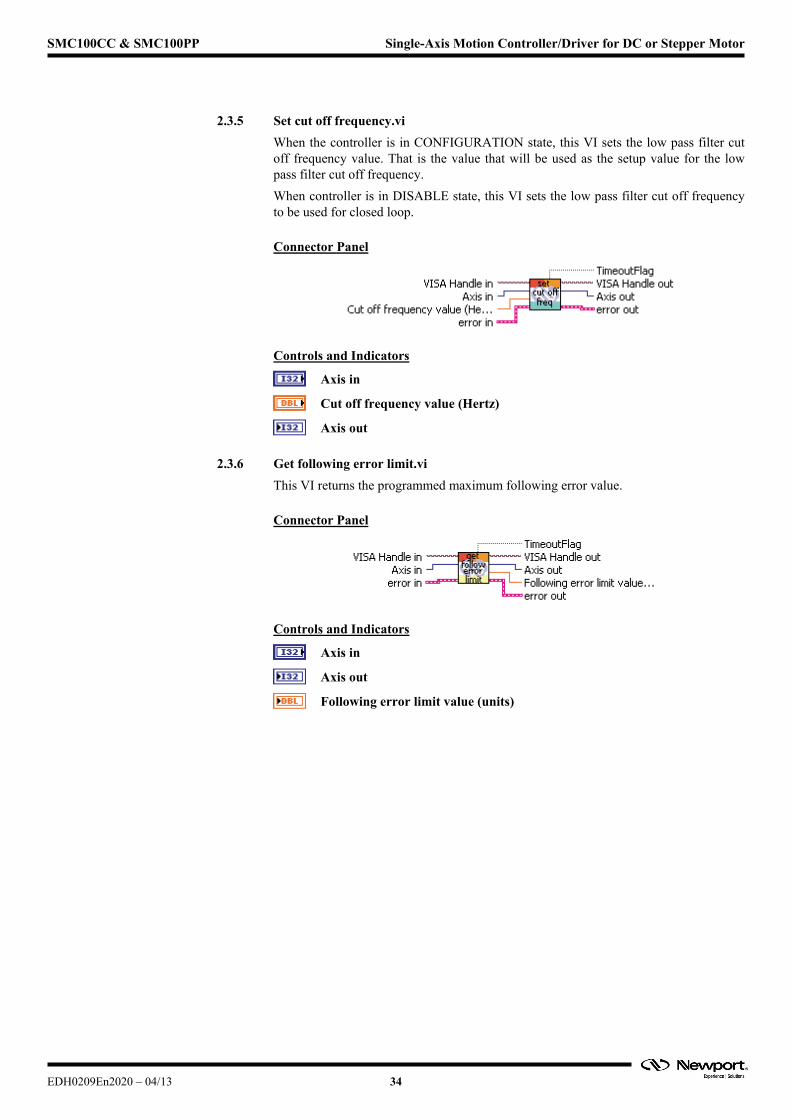
2.3.5 Set cut off frequency.vi
When the controller is in CONFIGURATION state, this VI sets the low pass filter cut off frequency value. That is the value that will be used as the setup value for the low pass filter cut off frequency.
When controller is in DISABLE state, this VI sets the low pass filter cut off frequency to be used for closed loop.
Connector Panel
Controls and Indicators
Axis in
Cut off frequency value (Hertz)
Axis out
2.3.6 Get following error limit.vi
This VI returns the programmed maximum following error value.
Connector Panel
Controls and Indicators
Axis in
Axis out
Following error limit value (units)
EDH0209En2020 – 04/13 34
SMC100CC & SMC100PP Single-Axis Motion Controller/Driver for DC or Stepper Motor
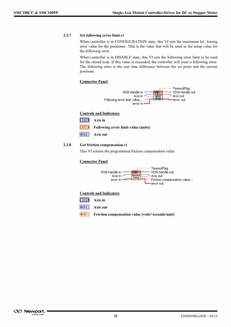
2.3.7 Set following error limit.vi
When controller is in CONFIGURATION state, this VI sets the maximum fol- lowing error value for the positioner. That is the value that will be used as the setup value for the following error.
When controller is in DISABLE state, this VI sets the following error limit to be used for the closed loop. If this value is exceeded, the controller will issue a following error. The following error is the real time difference between the set point and the current positions.
Connector Panel
Controls and Indicators
Axis in
Following error limit value (units)
Axis out
2.3.8 Get friction compensation.vi
This VI returns the programmed friction compensation value.
Connector Panel
Controls and Indicators
Axis in
Axis out
Friction compensation value (volts*seconds/unit)
35 EDH0209En2020 – 04/13
SMC100CC & SMC100PP Single-Axis Motion Controller/Driver for DC or Stepper Motor
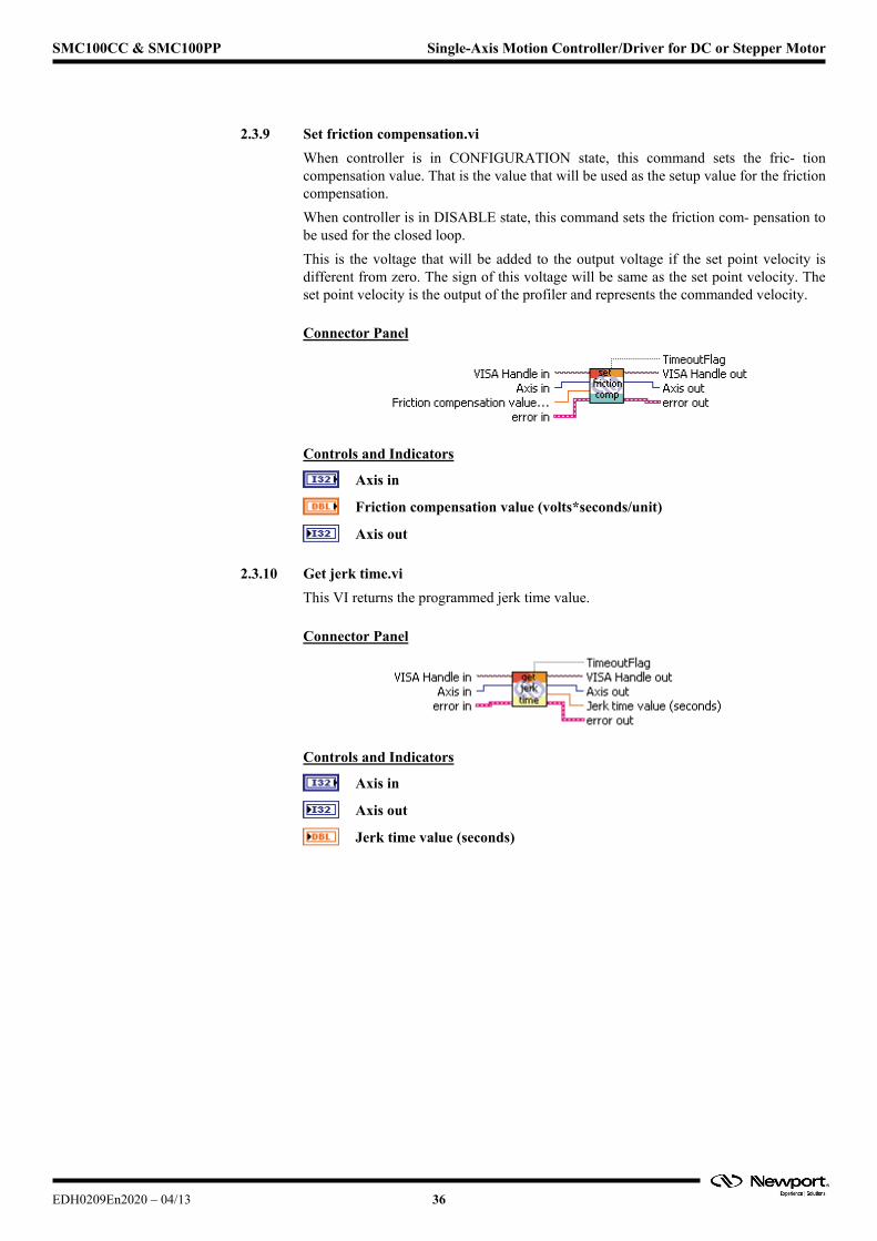
2.3.9 Set friction compensation.vi
When controller is in CONFIGURATION state, this command sets the fric- tion compensation value. That is the value that will be used as the setup value for the friction compensation.
When controller is in DISABLE state, this command sets the friction com- pensation to be used for the closed loop.
This is the voltage that will be added to the output voltage if the set point velocity is different from zero. The sign of this voltage will be same as the set point velocity. The set point velocity is the output of the profiler and represents the commanded velocity.
Connector Panel
Controls and Indicators
Axis in
Friction compensation value (volts*seconds/unit)
Axis out
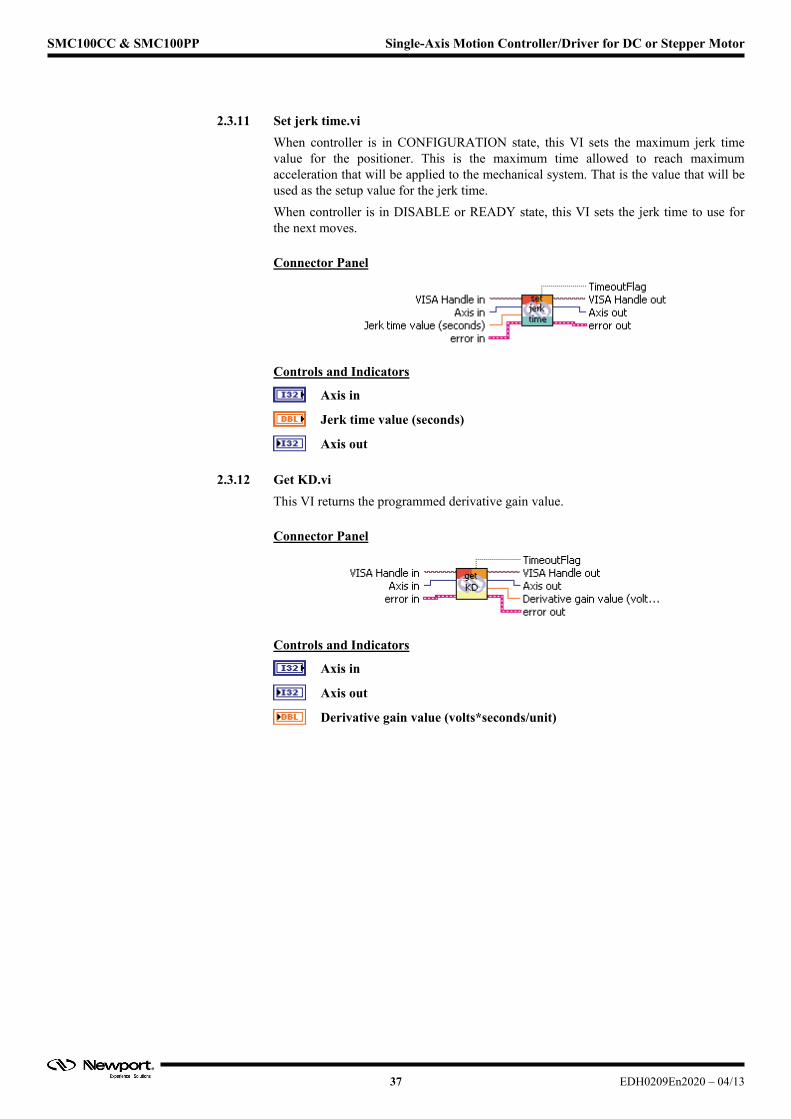
2.3.10 Get jerk time.vi
This VI returns the programmed jerk time value.
Connector Panel
Controls and Indicators
Axis in
Axis out
Jerk time value (seconds)
EDH0209En2020 – 04/13 36
SMC100CC & SMC100PP Single-Axis Motion Controller/Driver for DC or Stepper Motor
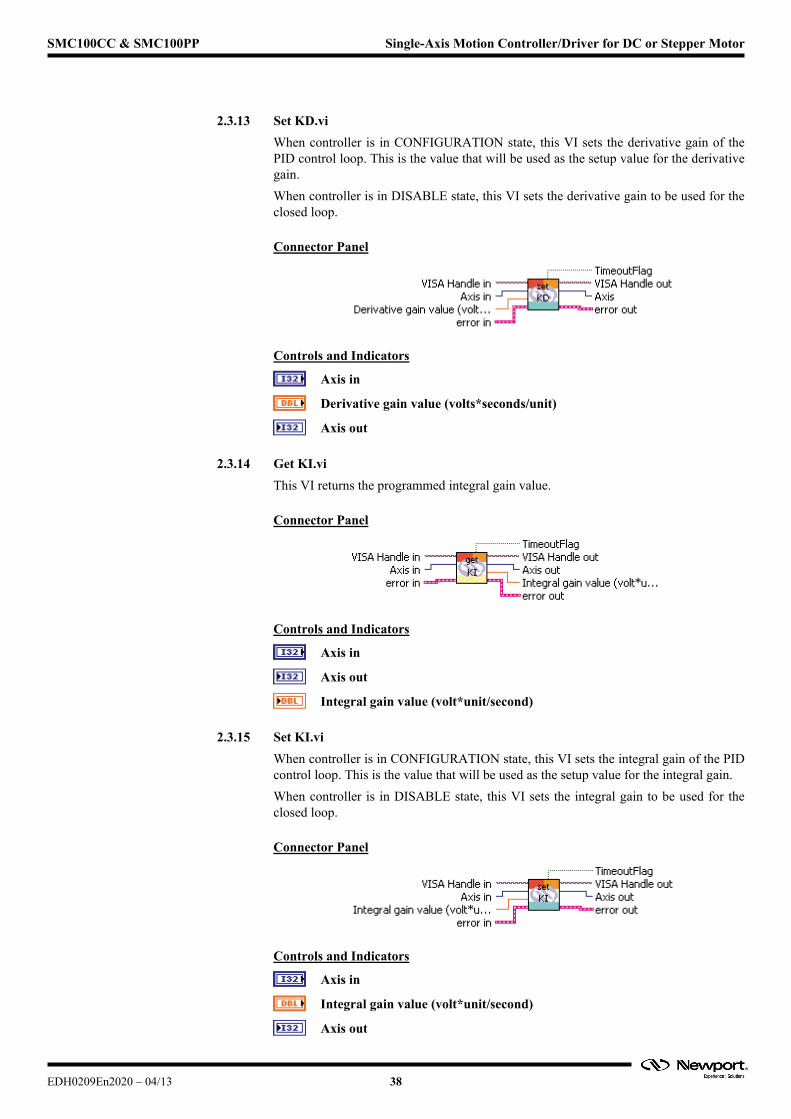
2.3.11 Set jerk time.vi
When controller is in CONFIGURATION state, this VI sets the maximum jerk time value for the positioner. This is the maximum time allowed to reach maximum acceleration that will be applied to the mechanical system. That is the value that will be used as the setup value for the jerk time.
When controller is in DISABLE or READY state, this VI sets the jerk time to use for the next moves.
Connector Panel
Controls and Indicators
Axis in
Jerk time value (seconds)
Axis out
2.3.12 Get KD.vi
This VI returns the programmed derivative gain value.
Connector Panel
Controls and Indicators
Axis in
Axis out
Derivative gain value (volts*seconds/unit)
37 EDH0209En2020 – 04/13
SMC100CC & SMC100PP Single-Axis Motion Controller/Driver for DC or Stepper Motor
2.3.13 Set KD.vi
When controller is in CONFIGURATION state, this VI sets the derivative gain of the PID control loop. This is the value that will be used as the setup value for the derivative gain.
When controller is in DISABLE state, this VI sets the derivative gain to be used for the closed loop.
Connector Panel
Controls and Indicators
Axis in
Derivative gain value (volts*seconds/unit)
Axis out
2.3.14 Get KI.vi
This VI returns the programmed integral gain value.
Connector Panel
Controls and Indicators
Axis in
Axis out
Integral gain value (volt*unit/second)
2.3.15 Set KI.vi
When controller is in CONFIGURATION state, this VI sets the integral gain of the PID control loop. This is the value that will be used as the setup value for the integral gain.
When controller is in DISABLE state, this VI sets the integral gain to be used for the closed loop.
Connector Panel
Controls and Indicators
Axis in
Integral gain value (volt*unit/second)
Axis out
EDH0209En2020 – 04/13 38

SMC100CC & SMC100PP Single-Axis Motion Controller/Driver for DC or Stepper Motor
2.3.16 Get KP.vi
This VI returns the programmed proportional gain value.
Connector Panel
Controls and Indicators
Axis in
Axis out
Proportional gain value (volts/unit)
2.3.17 Set KP.vi
When controller is in CONFIGURATION state, this VI sets the proportional gain of the PID control loop. This is the value that will be used as the setup value for the proportional gain.
When controller is in DISABLE state, this VI sets the proportional gain to be used for the closed loop.
Connector Panel
Controls and Indicators
Axis in
Proportional gain value (volts/unit)
Axis out
2.3.18 Get negative position limit.vi
This VI returns the programmed negative software position limit value for the positioner.
Connector Panel
Controls and Indicators
Axis in
Axis out
Negative software position limit (units)
39 EDH0209En2020 – 04/13
SMC100CC & SMC100PP Single-Axis Motion Controller/Driver for DC or Stepper Motor
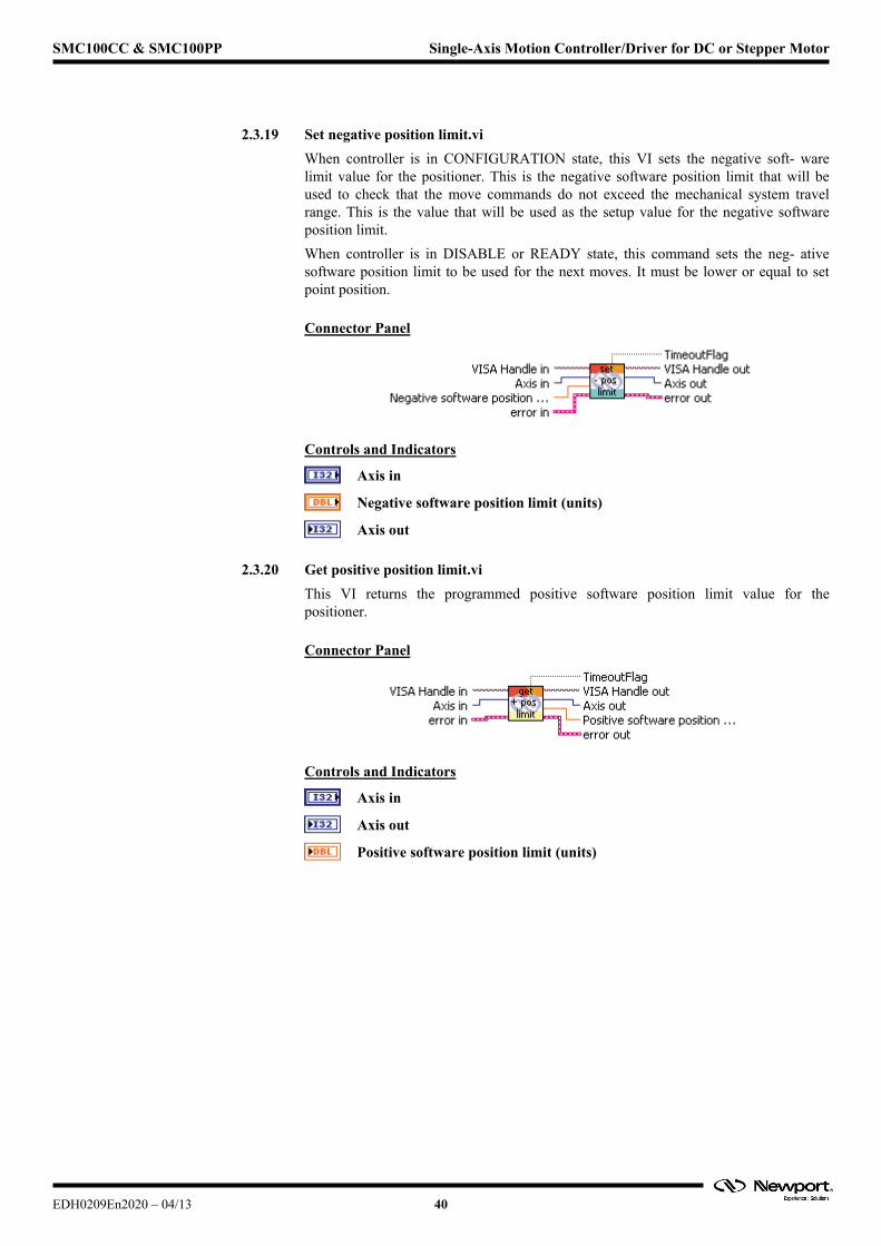
2.3.19 Set negative position limit.vi
When controller is in CONFIGURATION state, this VI sets the negative soft- ware limit value for the positioner. This is the negative software position limit that will be used to check that the move commands do not exceed the mechanical system travel range. This is the value that will be used as the setup value for the negative software position limit.
When controller is in DISABLE or READY state, this command sets the neg- ative software position limit to be used for the next moves. It must be lower or equal to set point position.
Connector Panel
Controls and Indicators
Axis in
Negative software position limit (units)
Axis out
2.3.20 Get positive position limit.vi
This VI returns the programmed positive software position limit value for the positioner.
Connector Panel
Controls and Indicators
Axis in
Axis out
Positive software position limit (units)
EDH0209En2020 – 04/13 40
SMC100CC & SMC100PP Single-Axis Motion Controller/Driver for DC or Stepper Motor
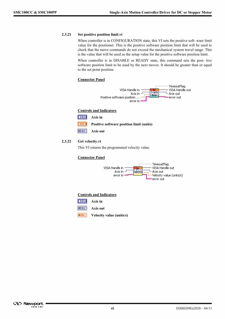
2.3.21 Set positive position limit.vi
When controller is in CONFIGURATION state, this VI sets the positive soft- ware limit value for the positioner. This is the positive software position limit that will be used to check that the move commands do not exceed the mechanical system travel range. This is the value that will be used as the setup value for the positive software position limit.
When controller is in DISABLE or READY state, this command sets the posi- tive software position limit to be used by the next moves. It should be greater than or equal to the set point position.
Connector Panel
Controls and Indicators
Axis in
Positive software position limit (units)
Axis out
2.3.22 Get velocity.vi
This VI returns the programmed velocity value.
Connector Panel
Controls and Indicators
Axis in
Axis out
Velocity value (units/s)
41 EDH0209En2020 – 04/13

SMC100CC & SMC100PP Single-Axis Motion Controller/Driver for DC or Stepper Motor
2.3.23 Set velocity.vi
When controller is in CONFIGURATION state, this VI sets the maximum velocity value for the positioner. This is the maximum velocity that will be applied to the mechanical system. This is the value that will be used as the setup value for the velocity.
When controller is in DISABLE or READY state, this command sets the velocity to be used for the next moves.
Connector Panel
Controls and Indicators
Axis in
Velocity value (units/s)
Axis out
2.3.24 Get velocity feed forward.vi
This VI returns the programmed velocity feed forward value.
Connector Panel
Controls and Indicators
Axis in
Axis out
Velocity feed forward value (volts*seconds/unit)
EDH0209En2020 – 04/13 42
SMC100CC & SMC100PP Single-Axis Motion Controller/Driver for DC or Stepper Motor
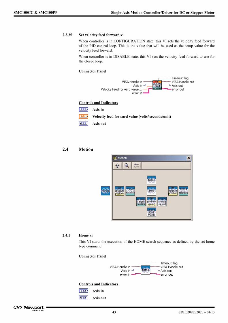
2.3.25 Set velocity feed forward.vi
When controller is in CONFIGURATION state, this VI sets the velocity feed forward of the PID control loop. This is the value that will be used as the setup value for the velocity feed forward.
When controller is in DISABLE state, this VI sets the velocity feed forward to use for the closed loop.
Connector Panel
Controls and Indicators
Axis in
Velocity feed forward value (volts*seconds/unit)
Axis out
2.4 Motion
2.4.1 Home.vi
This VI starts the execution of the HOME search sequence as defined by the set home type command.
Connector Panel
Controls and Indicators
Axis in
Axis out
43 EDH0209En2020 – 04/13
SMC100CC & SMC100PP Single-Axis Motion Controller/Driver for DC or Stepper Motor
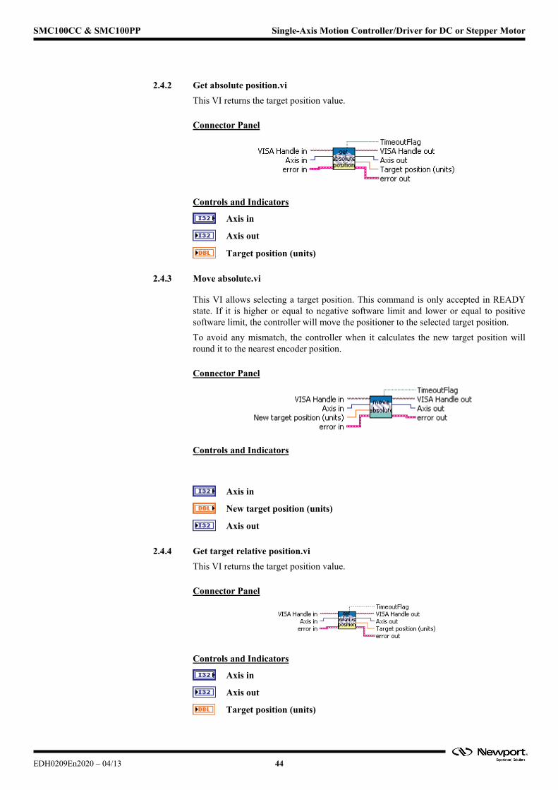
2.4.2 Get absolute position.vi
This VI returns the target position value.
Connector Panel
Controls and Indicators
Axis in
Axis out
Target position (units)
2.4.3 Move absolute.vi
This VI allows selecting a target position. This command is only accepted in READY state. If it is higher or equal to negative software limit and lower or equal to positive software limit, the controller will move the positioner to the selected target position.
To avoid any mismatch, the controller when it calculates the new target position will round it to the nearest encoder position.
Connector Panel
Controls and Indicators
Axis in
New target position (units)
Axis out
2.4.4 Get target relative position.vi
This VI returns the target position value.
Connector Panel
Controls and Indicators
Axis in
Axis out
Target position (units)
EDH0209En2020 – 04/13 44
SMC100CC & SMC100PP Single-Axis Motion Controller/Driver for DC or Stepper Motor
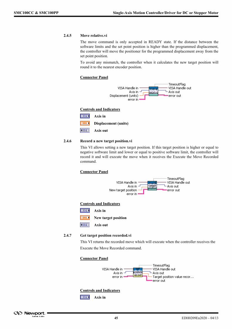
2.4.5 Move relative.vi
The move command is only accepted in READY state. If the distance between the software limits and the set point position is higher than the programmed displacement, the controller will move the positioner for the programmed displacement away from the set point position.
To avoid any mismatch, the controller when it calculates the new target position will round it to the nearest encoder position.
Connector Panel
Controls and Indicators
Axis in
Displacement (units)
Axis out
2.4.6 Record a new target position.vi
This VI allows setting a new target position. If this target position is higher or equal to negative software limit and lower or equal to positive software limit, the controller will record it and will execute the move when it receives the Execute the Move Recorded command.
Connector Panel
Controls and Indicators
Axis in
New target position
Axis out
2.4.7 Get target position recorded.vi
This VI returns the recorded move which will execute when the controller receives the
Execute the Move Recorded command.
Connector Panel
Controls and Indicators
Axis in
45 EDH0209En2020 – 04/13
SMC100CC & SMC100PP Single-Axis Motion Controller/Driver for DC or Stepper Motor
Axis out
Target position value recorded (units)
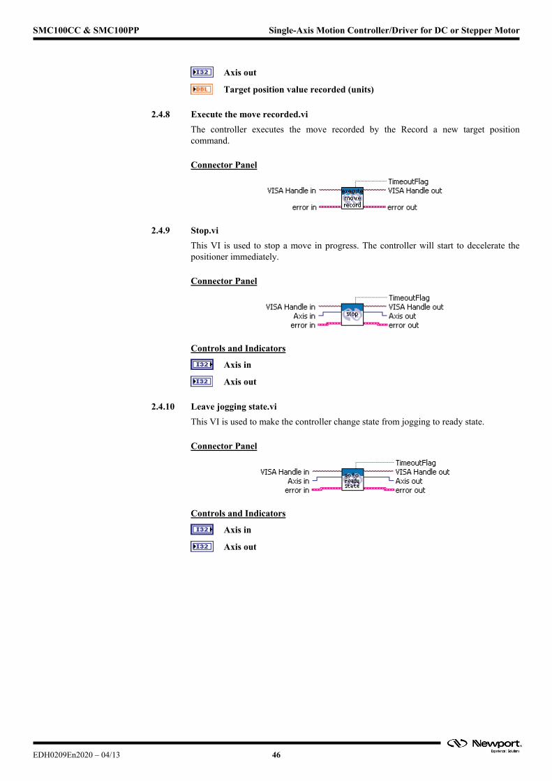
2.4.8 Execute the move recorded.vi
The controller executes the move recorded by the Record a new target position command.
Connector Panel
2.4.9 Stop.vi
This VI is used to stop a move in progress. The controller will start to decelerate the positioner immediately.
Connector Panel
Controls and Indicators
Axis in
Axis out
2.4.10 Leave jogging state.vi
This VI is used to make the controller change state from jogging to ready state.
Connector Panel
Controls and Indicators
Axis in
Axis out
EDH0209En2020 – 04/13 46
SMC100CC & SMC100PP Single-Axis Motion Controller/Driver for DC or Stepper Motor
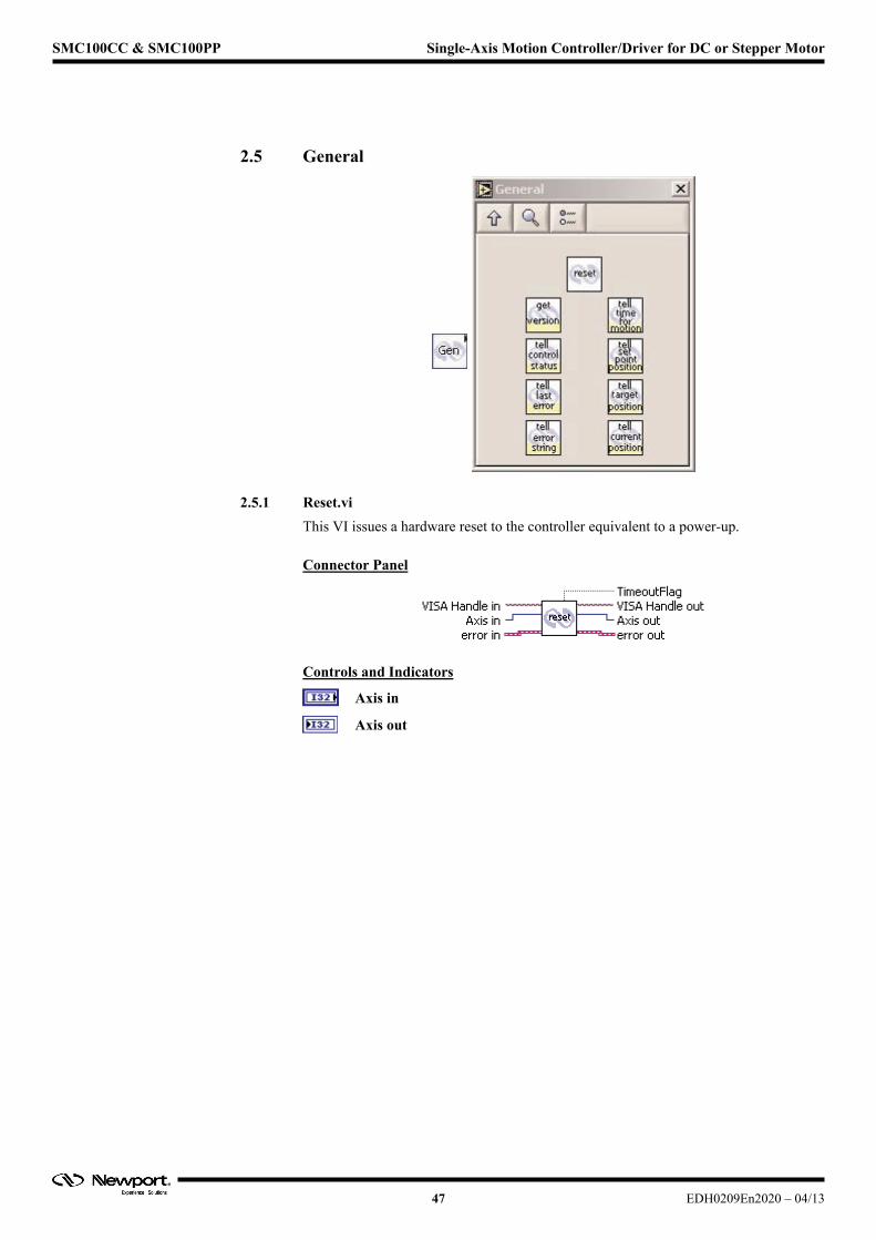
2.5 General
2.5.1 Reset.vi
This VI issues a hardware reset to the controller equivalent to a power-up.
Connector Panel
Controls and Indicators
Axis in
Axis out
47 EDH0209En2020 – 04/13
SMC100CC & SMC100PP Single-Axis Motion Controller/Driver for DC or Stepper Motor
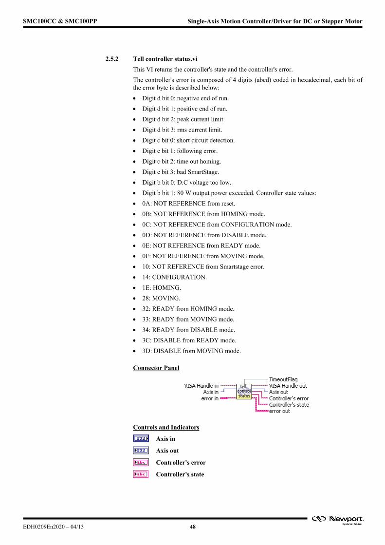
2.5.2 Tell controller status.vi
This VI returns the controller's state and the controller's error.
The controller's error is composed of 4 digits (abcd) coded in hexadecimal, each bit of the error byte is described below:
Digit d bit 0: negative end of run.
Digit d bit 1: positive end of run.
Digit d bit 2: peak current limit.
Digit d bit 3: rms current limit.
Digit c bit 0: short circuit detection.
Digit c bit 1: following error.
Digit c bit 2: time out homing.
Digit c bit 3: bad SmartStage.
Digit b bit 0: D.C voltage too low.
Digit b bit 1: 80 W output power exceeded. Controller state values:
0A: NOT REFERENCE from reset.
0B: NOT REFERENCE from HOMING mode.
0C: NOT REFERENCE from CONFIGURATION mode.
0D: NOT REFERENCE from DISABLE mode.
0E: NOT REFERENCE from READY mode.
0F: NOT REFERENCE from MOVING mode.
10: NOT REFERENCE from Smartstage error.
14: CONFIGURATION.
1E: HOMING.
28: MOVING.
32: READY from HOMING mode.
33: READY from MOVING mode.
34: READY from DISABLE mode.
3C: DISABLE from READY mode.
3D: DISABLE from MOVING mode.
Connector Panel
Controls and Indicators
Axis in
Axis out
Controller's error
Controller's state
EDH0209En2020 – 04/13 48
SMC100CC & SMC100PP Single-Axis Motion Controller/Driver for DC or Stepper Motor
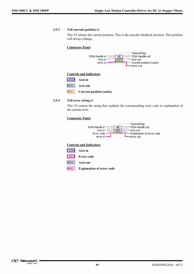
2.5.3 Tell current position.vi
This VI returns the current position. This is the encoder feedback position. This position will always change.
Connector Panel
Controls and Indicators
Axis in
Axis out
Current position (units)
2.5.4 Tell error string.vi
This VI returns the string that explains the corresponding error code or explanation of the current error.
Connector Panel
Controls and Indicators
Axis in
Error code
Axis out
Explanation of error code
49 EDH0209En2020 – 04/13
SMC100CC & SMC100PP Single-Axis Motion Controller/Driver for DC or Stepper Motor
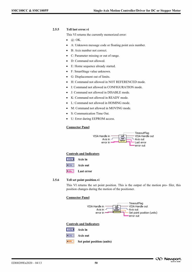
2.5.5 Tell last error.vi
This VI returns the currently memorized error:
@: OK.
A: Unknown message code or floating point axis number.
B: Axis number not correct.
C: Parameter missing or out of range.
D: Command not allowed.
E: Home sequence already started.
F: SmartStage value unknown.
G: Displacement out of limits.
H: Command not allowed in NOT REFERENCED mode.
I: Command not allowed in CONFIGURATION mode.
J: Command not allowed in DISABLE mode.
K: Command not allowed in READY mode.
L: Command not allowed in HOMING mode.
M: Command not allowed in MOVING mode.
S: Communication Time Out.
U: Error during EEPROM access.
Connector Panel
Controls and Indicators
Axis in
Axis out
Last error
2.5.6 Tell set point position.vi
This VI returns the set point position. This is the output of the motion pro- filer, this position changes during the motion of the positioner.
Connector Panel
Controls and Indicators
Axis in
Axis out
Set point position (units)
EDH0209En2020 – 04/13 50

SMC100CC & SMC100PP Single-Axis Motion Controller/Driver for DC or Stepper Motor
2.5.7 Tell target position.vi
This VI returns the target position. This is the final position the positioner will reach.
Connector Panel
Controls and Indicators
Axis in
Axis out
Current position (units)
2.5.8 Tell time for a relative motion.vi
The controller will not execute any motion, it will return the time, in sec- onds, necessary to execute the displacement with the current setup para- meters.
Connector Panel
Controls and Indicators
Axis in
Displacement (units)
Axis out
Time to move (seconds)
2.5.9 Get version.vi
This VI returns the controller's revision information.
Connector Panel
Controls and Indicators
Axis in
Axis out
Version
51 EDH0209En2020 – 04/13
SMC100CC & SMC100PP Single-Axis Motion Controller/Driver for DC or Stepper Motor
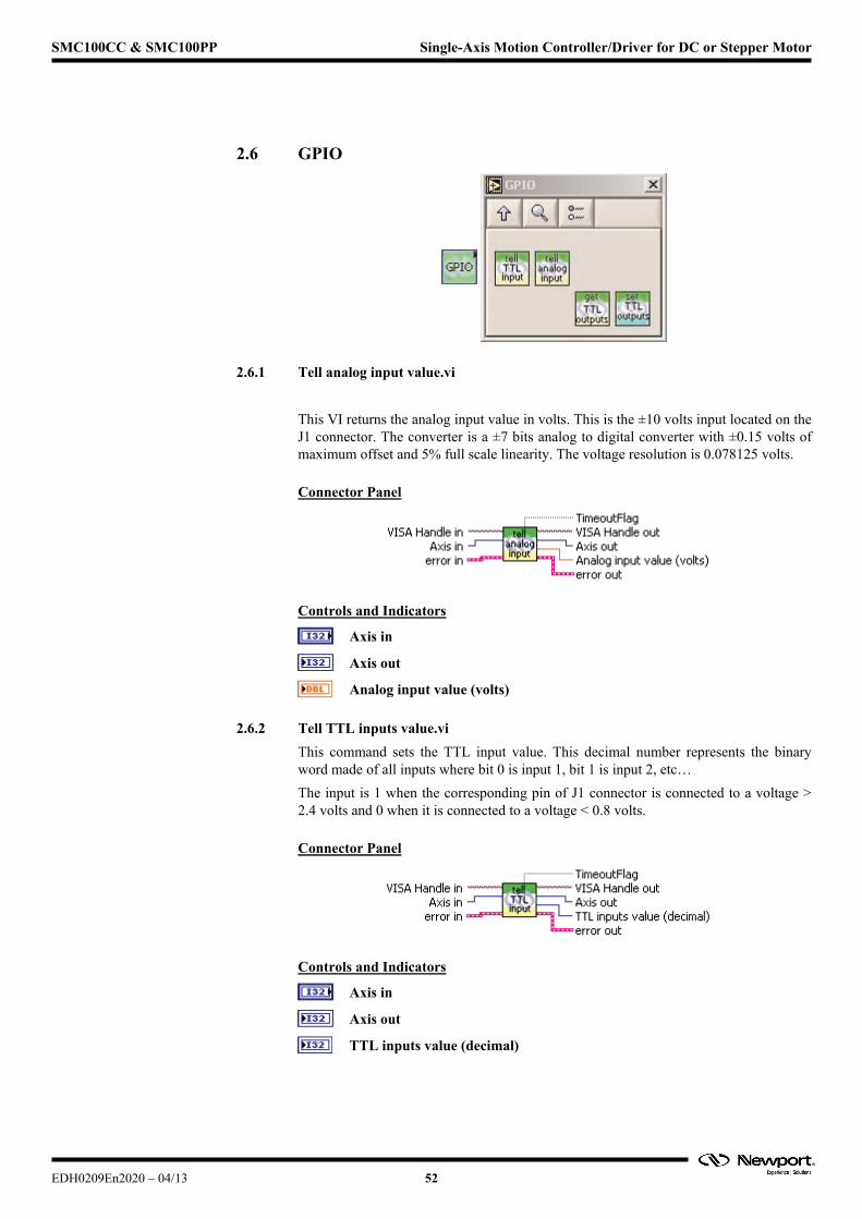
2.6 GPIO
2.6.1 Tell analog input value.vi
This VI returns the analog input value in volts. This is the ±10 volts input located on the J1 connector. The converter is a ±7 bits analog to digital converter with ±0.15 volts of maximum offset and 5% full scale linearity. The voltage resolution is 0.078125 volts.
Connector Panel
Controls and Indicators
Axis in
Axis out
Analog input value (volts)
2.6.2 Tell TTL inputs value.vi
This command sets the TTL input value. This decimal number represents the binary word made of all inputs where bit 0 is input 1, bit 1 is input 2, etc…
The input is 1 when the corresponding pin of J1 connector is connected to a voltage > 2.4 volts and 0 when it is connected to a voltage < 0.8 volts.
Connector Panel
Controls and Indicators
Axis in
Axis out
TTL inputs value (decimal)
EDH0209En2020 – 04/13 52
SMC100CC & SMC100PP Single-Axis Motion Controller/Driver for DC or Stepper Motor
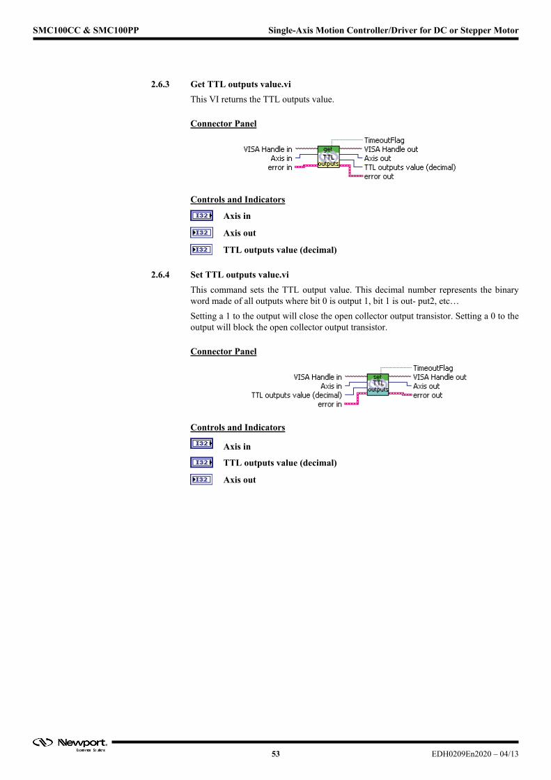
2.6.3 Get TTL outputs value.vi
This VI returns the TTL outputs value.
Connector Panel
Controls and Indicators
Axis in
Axis out
TTL outputs value (decimal)
2.6.4 Set TTL outputs value.vi
This command sets the TTL output value. This decimal number represents the binary word made of all outputs where bit 0 is output 1, bit 1 is out- put2, etc…
Setting a 1 to the output will close the open collector output transistor. Setting a 0 to the output will block the open collector output transistor.
Connector Panel
Controls and Indicators
Axis in
TTL outputs value (decimal)
Axis out
53 EDH0209En2020 – 04/13
SMC100CC & SMC100PP Single-Axis Motion Controller/Driver for DC or Stepper Motor
EDH0209En2020 – 04/13 54
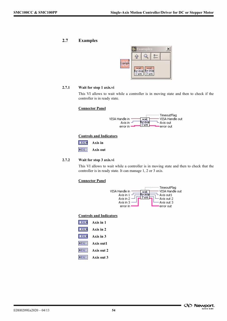
2.7 Examples
2.7.1 Wait for stop 1 axis.vi
This VI allows to wait while a controller is in moving state and then to check if the controller is in ready state.
Connector Panel
Controls and Indicators
Axis in
Axis out
2.7.2 Wait for stop 3 axis.vi
This VI allows to wait while a controller is in moving state and then to check that the controller is in ready state. It can manage 1, 2 or 3 axis.
Connector Panel
Controls and Indicators
Axis in 1
Axis in 2
Axis in 3
Axis out1
Axis out 2
Axis out 3
SMC100CC & SMC100PP Single-Axis Motion Controller/Driver for DC or Stepper Motor
Service Form Your Local Representative
Tel.: ___________________
Fax: ___________________
Name: __________________________________________________ Return authorization #: _____________________________________
Company: _______________________________________________ (Please obtain prior to return of item)
Address:_________________________________________________ Date: ___________________________________________________
Country:_________________________________________________ Phone Number: ___________________________________________
P.O. Number: ____________________________________________ Fax Number: _____________________________________________
Item(s) Being Returned: ____________________________________
Model#: _________________________________________________ Serial #: _________________________________________________
Description:__________________________________________________________________________________________________________
Reasons of return of goods (please list any specific problems):__________________________________________________________________
____________________________________________________________________________________________________________________
____________________________________________________________________________________________________________________
____________________________________________________________________________________________________________________
____________________________________________________________________________________________________________________
____________________________________________________________________________________________________________________
____________________________________________________________________________________________________________________
____________________________________________________________________________________________________________________
____________________________________________________________________________________________________________________
____________________________________________________________________________________________________________________
____________________________________________________________________________________________________________________
____________________________________________________________________________________________________________________
____________________________________________________________________________________________________________________
____________________________________________________________________________________________________________________
____________________________________________________________________________________________________________________
____________________________________________________________________________________________________________________
____________________________________________________________________________________________________________________
____________________________________________________________________________________________________________________
____________________________________________________________________________________________________________________
____________________________________________________________________________________________________________________
____________________________________________________________________________________________________________________
____________________________________________________________________________________________________________________
____________________________________________________________________________________________________________________
____________________________________________________________________________________________________________________
____________________________________________________________________________________________________________________
____________________________________________________________________________________________________________________
____________________________________________________________________________________________________________________
____________________________________________________________________________________________________________________
____________________________________________________________________________________________________________________
EDH0209En2020 – 04/13 55

Visit Newport Online at:www.newport.com
North America & Asia Newport Corporation 1791 Deere Ave. Irvine, CA 92606, USA
Sales Tel.: (800) 222-6440 e-mail: [email protected]
Technical Support Tel.: (800) 222-6440 e-mail: [email protected]
Service, RMAs & Returns Tel.: (800) 222-6440 e-mail: [email protected]
Europe MICRO-CONTROLE Spectra-Physics S.A.S9, rue du Bois Sauvage 91055 Évry CEDEX France
Sales Tel.: +33 (0)1.60.91.68.68 e-mail: [email protected]
Technical Support e-mail: [email protected]
Service & Returns Tel.: +33 (0)2.38.40.51.55


