Single Bidirectional Infrared LED Communication Port Reference Design
TI DesignsSingle Bidirectional Infrared LED Communication PortReference Design
DescriptionInfrared (IR) optical ports are still very popular in ultra-low-power metering and sub-metering applicationssuch as heat cost allocators, gas, water, and heatmeters. Typical use cases are configuring andactivating the meters during manufacturing or fieldinstallation as well as manual readout of billing datausing handheld readers. Bidirectional communicationper IrDA PHY specification with a 9600-bps data rateis quite common. This very low-cost and ultra-low-power implementation is using a single IR LED fortransmitting and receiving data with the algorithmimplemented inside the sensor controller engine of aCC1350 Wireless MCU.
Features• CC1350 SimpleLink™ Wireless MCU• Only Two I/Os Required for Bidirectional IR Port
Communication With Internal Fixed 1.27-VReference
• Four I/Os Required (if External Voltage Divider as aFixed Reference is Used)
• Sensor Controller Engine Controls IR LED toReceive and Transmit IR Data at 9600 bps
• Average Current of 1.73 µA at 3.0 V WithCapTouchButton and IR LED Polling Every1 Second
Applications• Heat Cost Allocators• Water Meter• Heat Meter• Gas Meter• Any Metering and Sub-Metering Systems With IrDA
9600-bps Communication Port
An IMPORTANT NOTICE at the end of this TI reference design addresses authorized use, intellectual property matters and otherimportant disclaimers and information.
Single Bidirectional Infrared LED Communication Port Reference Design
1 System OverviewMany, if not all, metering and sub-metering applications require support for bi-directional infrared (IR) LEDcommunication, which is the dominant low-cost common interface used during manufacturing and later asa maintenance, configuration interface, or for reading out sub-metering data or internal system parameterswith a handheld or a mobile device. Some EU standards like EN1434-3 for heat meters require opticalinterface as per EN62056-21, where two separate IR LEDs are used (one for receive and one fortransmit). The IEC62056-21 (also known as EN62056-21 in Europe) IR communication is quite popularwith electricity meters throughout the world.
Near field communications (NFC) and Bluetooth® Low Energy (BLE) technologies are becoming more andmore popular through the integration into smart phones and tablets and can be considered as a possibleIR replacement solution; however, the higher component cost, the missing directivity of the RFtransmission, and the associated RF certification efforts for these RF technologies limit their mass marketdeployment as a configuration and maintenance interface in smart metering and sub-metering products sofar.
The majority of metering applications (except E-meters) are often powered by primary batteries and thusneed a lowest power implementation of IR and RF communications. Gas, water, and heat meters as wellas heat cost allocator (HCA) products are widely deployed battery-operated metering and sub-meteringproducts.
There are no fixed requirements for supporting an IR port neither in the EN4064-1 through EN4064-5(water meter normative documents) nor in EN1434-1 through EN1434-6 (heat meter specifications).Nevertheless, almost all existing water and heat meter products and HCAs provide some type of IRinterface, enabling the setup and configuration in the field as well as the readout of the application data,using a handheld unit (HHU). The TIDA-01212 adds an IrDA serial infrared (SIR) optical portimplementation inside the sensor controller engine of a CC1350 Wireless MCU. In fact, both CC1350 andCC1310 devices have been tested, so this reference design applies to both (even if only CC1350 ismentioned in this design guide).
1.1 System DescriptionThere are various solutions for IR communications such as integrated TX/RX IR LED modules with twoLEDs, one for TX and one for RX operation, similar to the one described in the TFBS4650 IRDA ModuleSIR Transceiver product page[10]. The IrDA PHY specification defines multiple data rates, with 9600 bpsbeing the mandatory one. Much faster data rates of up to 16Mbps have been defined, though these arerelevant to other applications such as PCs, notebooks, and mobile phones.
Dual LED IR modules are easy to integrate and shorten the development time because they handle theamplification and demodulation of the IR signal. However, this functionality comes at a cost premium. Analternative approach is to handle the modulation and the demodulation within a MCU device, especially forthe slower IrDA SIR data rates of up to 115.2 kbps. The few MCU resources such as an ultra-low-powertimer and a comparator, which are required for supporting the IR protocol in both transmit and receive, areusually freely available in many MCUs, and having a dedicated LED for each direction makes softwareimplementation easier.
The TIDA-01212 introduces a simpler solution by using a single TSPF6200[7] IR LED instead of the dualLED approach. This is more software demanding, but at the same time the lowest component costsolution. The MCU handles the IR LED control for transmit and receive as well as the proper timings forthe bi-directional IR serial port communication. Note that a single IR LED in a smart meter device mayalso require a single IR LED in the reader (or HHU) to support both transmit and receive modes if the twoseparate IR LEDs are not sufficiently aligned with the single LED in the sub-metering device. Maximumspectral intensity in transmit is achieved along the axis of the LED. Any misalignment between transmitand receive IR LED reduces the spectral intensity and thus the range of the IR optical link.
Single Bidirectional Infrared LED Communication Port Reference Design
The capability of any IR LED to function as a receiver has been known since the 1970s due to Forrest W.Mims publications. Although being primarily a transmitter, an IR LED is sensitive typically to wavelengthsslightly below its own peak radiant power wavelength[5]. This fact enables the use of a single IR LED as abi-directional IR communication port. The TIDA-01212 represents such a bi-directional IR communicationsubsystem, supporting the mandatory 9600 bps data rate of the IrDA PHY1.4 specification. The TIDA-01212 solution can be integrated in any metering application and due to its simplicity and low-powerconsumption is aimed at smart gas, water, and heat meters and HCAs. A higher data rate than 9600 bpsis possible but has not been tested.
The main components of TIDA-01212 are:• CC1350 Wireless SoC (includes the sensor controller engine for ultra-low-power implementation)• TSPF6200 IR LED with 890-nm peak transmit wavelength and maximum spectral sensitivity at 860 to
870 nm
NOTE: TIDA-01212 has been also tested with the NEC infrared protocol for TV remote controls,example software and hardware setup is also documented.
1.2 Key System Specifications
Table 1. Key System Specifications
PARAMETER SPECIFICATIONS DETAILSOperating ambient temperature –40°C to 85°C (for CC1350/CC1310 and Vishay TSPF6200 IR LED) Section 1.4.1IR link data rate 9600 bps Section 2.5Current consumption(IrDA 9600 polling 1 per second) 1.7 µA at 3 V Section 3.6
IR NEC protocol for TV remote Example RX and TX code provided Section 3.4
1.3 Block Diagram
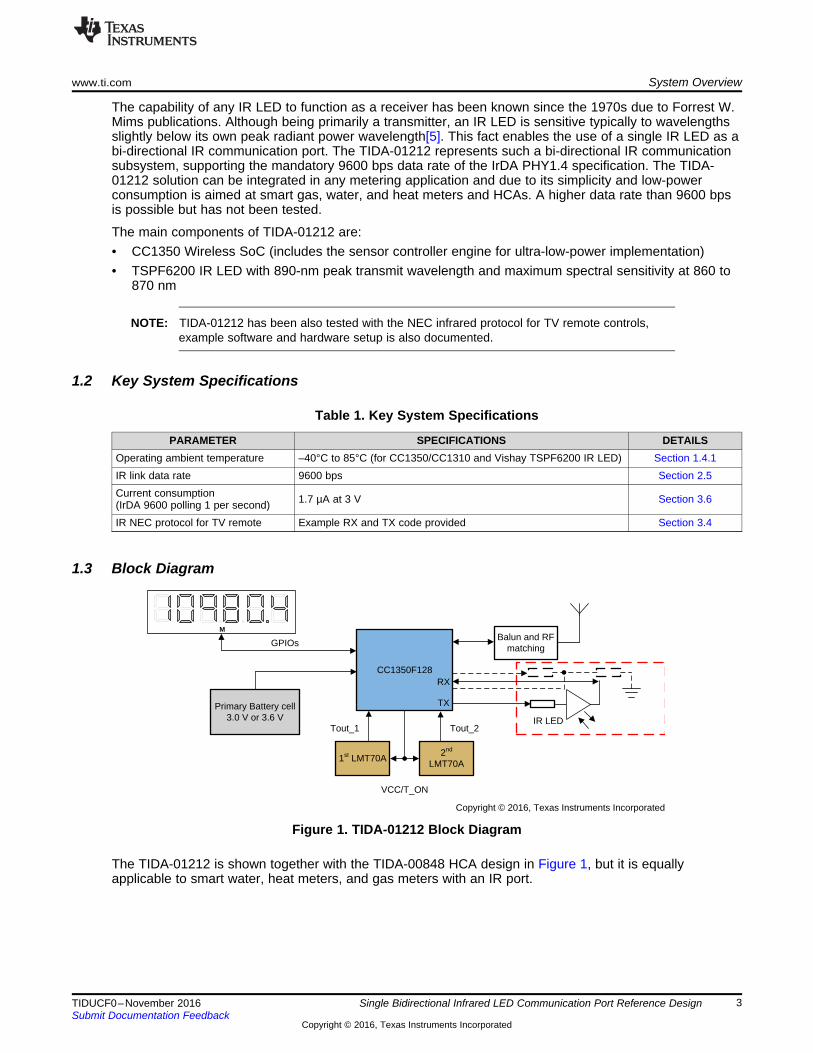
Figure 1. TIDA-01212 Block Diagram
The TIDA-01212 is shown together with the TIDA-00848 HCA design in Figure 1, but it is equallyapplicable to smart water, heat meters, and gas meters with an IR port.
Single Bidirectional Infrared LED Communication Port Reference Design
1.4 Highlighted Products
1.4.1 CC1350The CC1350 is the first device in the CC13xx and CC26xx family of cost-effective, ultra-low-powerwireless MCUs capable of handling both Sub-1 GHz and 2.4-GHz RF frequencies. The CC1350 devicecombines a flexible, very low-power RF transceiver with a powerful 48-MHz ARM® Cortex®-M3 MCU in aplatform supporting multiple physical layers and RF standards. A dedicated radio controller (Cortex-M0)handles low-level RF protocol commands that are stored in ROM or RAM, thus ensuring ultra-low powerand flexibility to handle both Sub-1 GHz protocols and 2.4-GHz protocols (for example, BLE; seeFigure 2).
Figure 2. CC1350 Block Diagram
The ARM Cortex-M3 runs with up to 48 MHz, and there is also 128KB of in-system programmable Flash,8KB of SRAM for cache (or as general-purpose RAM), and 20 KB of ultra-low leakage SRAM in thedevice. The sensor controller has been optimized for ultra-low power and can run autonomously from therest of the system at 24 MHz, using only 0.4 mA + 8.2 μA/MHz. The sensor controller has a 16-bitarchitecture, controls the 12-bit ADC hardware block, and has its dedicated 2KB of ultra-low leakageSRAM for code and data. The CC1310 standby current is typically 0.8 µA at 3.6 V when using XOSC_LF(with RTC running and RAM and data CPU retention). The sensor controller seamlessly interfaces to theIR LED and uses its internal TDC and COMPA (Comparator A) hardware blocks to deliver outstandinglow-power consumption while executing various tasks.
Single Bidirectional Infrared LED Communication Port Reference Design
2 Getting Started Hardware and Software
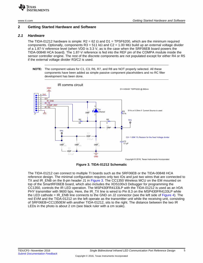
2.1 HardwareThe TIDA-01212 hardware is simple: R2 = 62 Ω and D1 = TPSF6200, which are the minimum requiredcomponents. Optionally, components R3 = 511 kΩ and C2 = 1.00 MΩ build up an external voltage dividerof a 1.87-V reference level (when VDD is 3.3 V, as is the case when the SRF06EB board powers theTIDA-00848 HCA board). The 1.87-V reference is fed into the REF pin of the COMPA module inside thesensor controller engine. The rest of the discrete components are not populated except for either R4 or R5if the external voltage divider R3/C2 is used.
NOTE: The component values for C1, C3, R6, R7, and R8 are NOT properly selected. All thesecomponents have been added as simple passive component placeholders and no RC filterdevelopment has been done.
Figure 3. TIDA-01212 Schematic
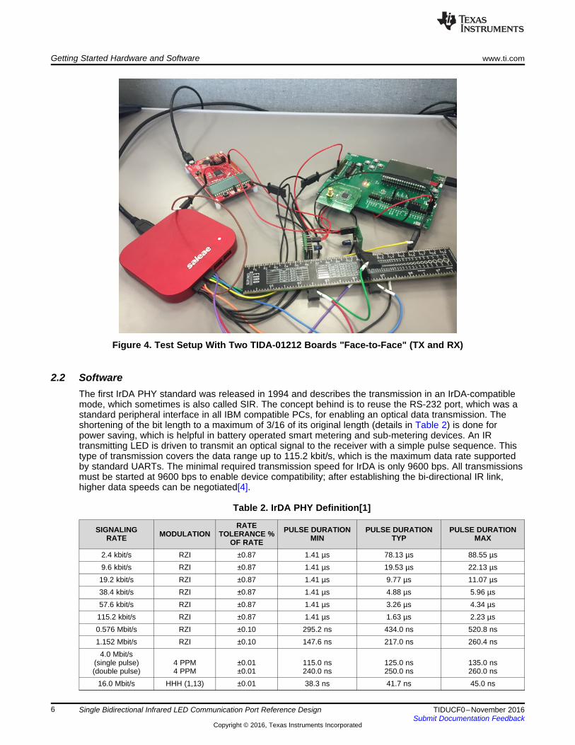
The TIDA-01212 can connect to multiple TI boards such as the SRF06EB or the TIDA-00848 HCAreference design. The minimal configuration requires only two IOs and just two wires that are connected toTX and IR_ENB on the 8-pin header J1 in Figure 3. The CC1350 Wireless MCU on the EM mounted ontop of the SmartRF06EB board, which also includes the XDS100v3 Debugger for programming theCC1350, controls the IR LED operation. The MSP430FR4133LP with the TIDA-01212 is used as an IrDAPHY transmitter with 9600 bps. Here, the IR_TX line is wired to Pin 8.3 on the MSP430FR4133LP whilethe LED cathode = IR_ENB line connects to the GND on J2 connector (see the left side of Figure 4). Thered EVM and the TIDA-01212 on the left operate as the transmitter unit while the receiving unit, consistingof SRF06EB+CC1350EM with another TIDA-01212, sits to the right. The distance between the two IRLEDs in the photo is about 2 cm (see black ruler with a cm scale).
Single Bidirectional Infrared LED Communication Port Reference Design
Figure 4. Test Setup With Two TIDA-01212 Boards "Face-to-Face" (TX and RX)
2.2 SoftwareThe first IrDA PHY standard was released in 1994 and describes the transmission in an IrDA-compatiblemode, which sometimes is also called SIR. The concept behind is to reuse the RS-232 port, which was astandard peripheral interface in all IBM compatible PCs, for enabling an optical data transmission. Theshortening of the bit length to a maximum of 3/16 of its original length (details in Table 2) is done forpower saving, which is helpful in battery operated smart metering and sub-metering devices. An IRtransmitting LED is driven to transmit an optical signal to the receiver with a simple pulse sequence. Thistype of transmission covers the data range up to 115.2 kbit/s, which is the maximum data rate supportedby standard UARTs. The minimal required transmission speed for IrDA is only 9600 bps. All transmissionsmust be started at 9600 bps to enable device compatibility; after establishing the bi-directional IR link,higher data speeds can be negotiated[4].
Single Bidirectional Infrared LED Communication Port Reference Design
2.3 IrDA PHY With 9600-bps ImplementationThe ultra-low-power software implementation of the IrDA receive and transmit operations is handled insidethe sensor controller engine (SCE) of the CC1350. The latter periodically enables and checks the IR LEDfor incoming signal when in receive mode. Typically, this is the default operational mode, where themetering node (for example, a water meter or HCA device) will be polling the IR LED for incoming wake-up command bytes. The polling period can be adjusted through the CCS open source code project bymodifying the TI RTOS period of the TRXIRLED task or by using a different tick sleep period in the SCEcommand: fwScheduleTask(1); //reschedule the task in 1 TI RTOS tick.
Typically, this polling period will be no longer than 2 to 3 seconds; in order to avoid such a long wake-upperiod, the TIDA-01212 example code uses 1 second for realistic duty cycle and power consumptionestimation. The 1-second period is also used for the CapTouchButton task (copied from the TIDA-00848design guide[2]) and allows the SCE to execute both tasks sequentially every second as a compromisebetween low-power consumption and acceptable IR response delay and CapTouch detection delay.
In addition, a separate SCE example code project additionally supports the popular NEC IR protocol,widely used in consumer electronic products such as TVs, SAT receivers, and so on. A short summary ofthis NEC IR protocol is found in the NEC Infrared Transmission Protocol[7].
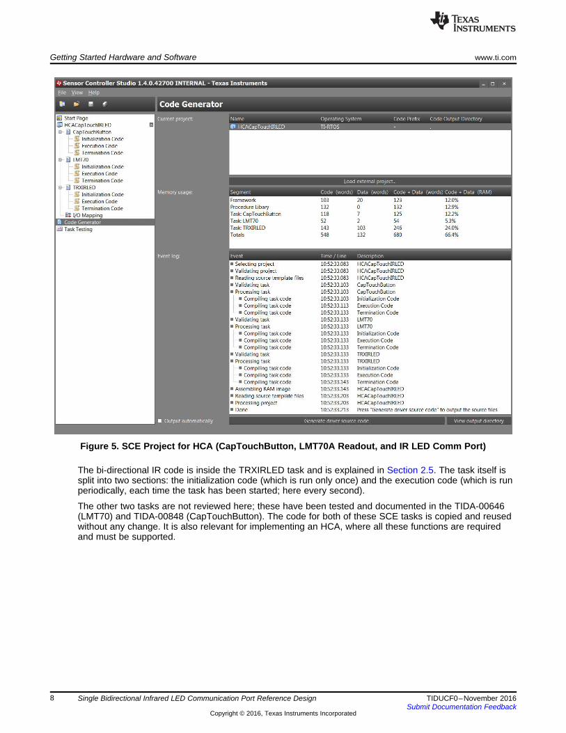
2.4 Sensor Controller Code ProjectThe SCE example code in the file "HCACapTouch_IRLED.scp" consists of three tasks required in an HCAdevice. Figure 5 shows that in total 66.4% of the 2KB RAM resources are used, which leaves someheadroom for adding code or some data buffering for the IR port communication in both transmit andreceive directions.
Single Bidirectional Infrared LED Communication Port Reference Design
Figure 5. SCE Project for HCA (CapTouchButton, LMT70A Readout, and IR LED Comm Port)
The bi-directional IR code is inside the TRXIRLED task and is explained in Section 2.5. The task itself issplit into two sections: the initialization code (which is run only once) and the execution code (which is runperiodically, each time the task has been started; here every second).
The other two tasks are not reviewed here; these have been tested and documented in the TIDA-00646(LMT70) and TIDA-00848 (CapTouchButton). The code for both of these SCE tasks is copied and reusedwithout any change. It is also relevant for implementing an HCA, where all these functions are requiredand must be supported.
Single Bidirectional Infrared LED Communication Port Reference Design
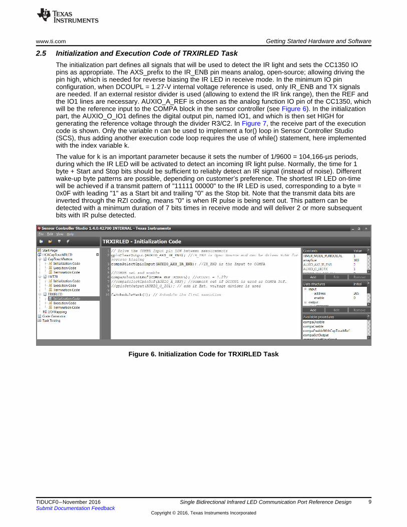
2.5 Initialization and Execution Code of TRXIRLED TaskThe initialization part defines all signals that will be used to detect the IR light and sets the CC1350 IOpins as appropriate. The AXS_prefix to the IR_ENB pin means analog, open-source; allowing driving thepin high, which is needed for reverse biasing the IR LED in receive mode. In the minimum IO pinconfiguration, when DCOUPL = 1.27-V internal voltage reference is used, only IR_ENB and TX signalsare needed. If an external resistor divider is used (allowing to extend the IR link range), then the REF andthe IO1 lines are necessary. AUXIO_A_REF is chosen as the analog function IO pin of the CC1350, whichwill be the reference input to the COMPA block in the sensor controller (see Figure 6). In the initializationpart, the AUXIO_O_IO1 defines the digital output pin, named IO1, and which is then set HIGH forgenerating the reference voltage through the divider R3/C2. In Figure 7, the receive part of the executioncode is shown. Only the variable n can be used to implement a for() loop in Sensor Controller Studio(SCS), thus adding another execution code loop requires the use of while() statement, here implementedwith the index variable k.
The value for k is an important parameter because it sets the number of 1/9600 = 104,166-µs periods,during which the IR LED will be activated to detect an incoming IR light pulse. Normally, the time for 1byte + Start and Stop bits should be sufficient to reliably detect an IR signal (instead of noise). Differentwake-up byte patterns are possible, depending on customer’s preference. The shortest IR LED on-timewill be achieved if a transmit pattern of "11111 00000" to the IR LED is used, corresponding to a byte =0x0F with leading "1" as a Start bit and trailing "0" as the Stop bit. Note that the transmit data bits areinverted through the RZI coding, means "0" is when IR pulse is being sent out. This pattern can bedetected with a minimum duration of 7 bits times in receive mode and will deliver 2 or more subsequentbits with IR pulse detected.
Single Bidirectional Infrared LED Communication Port Reference Design
In the code in Figure 7, k < 20 is an example to show the functionality of the implementation. For lowestaverage current consumption in the HCA or any other sub-metering device, depending on the transmitwake-up pattern, the shortest possible IR LED detection period is selected. In the measurement inSection 3.6, k < 7 has been used.
Figure 7. Execution Code for TRXIRLED Task (Receive Polling Example)
Single Bidirectional Infrared LED Communication Port Reference Design
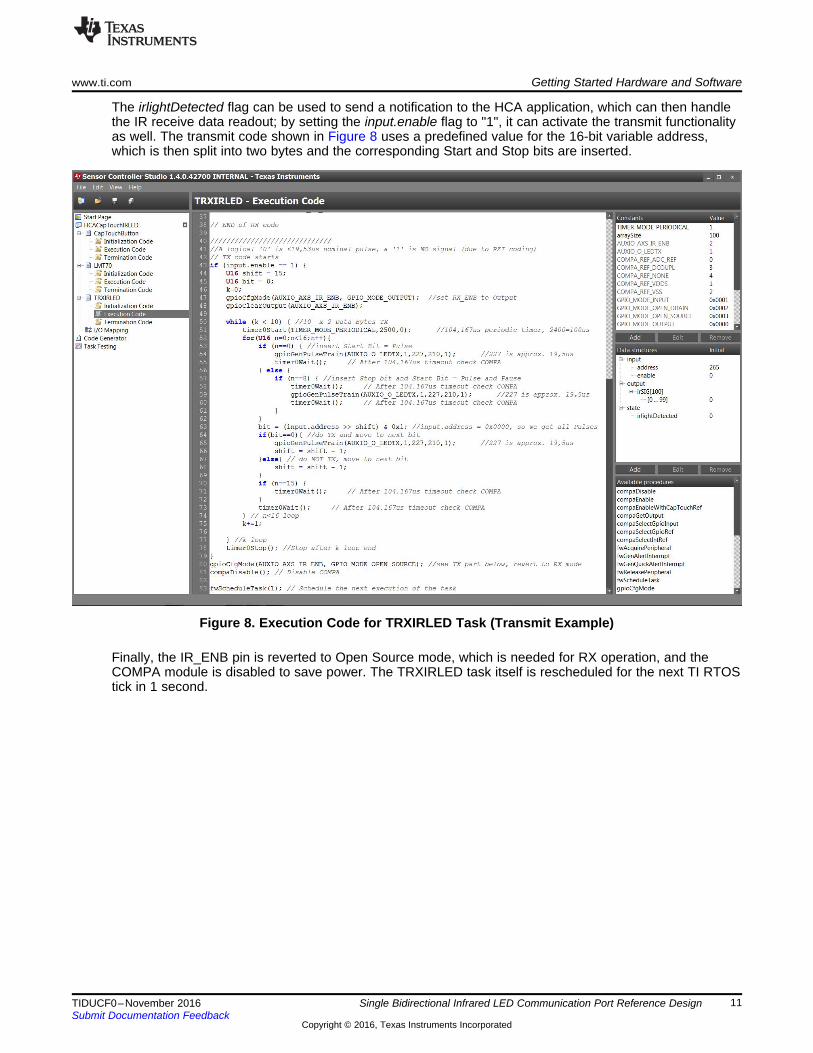
The irlightDetected flag can be used to send a notification to the HCA application, which can then handlethe IR receive data readout; by setting the input.enable flag to "1", it can activate the transmit functionalityas well. The transmit code shown in Figure 8 uses a predefined value for the 16-bit variable address,which is then split into two bytes and the corresponding Start and Stop bits are inserted.
Figure 8. Execution Code for TRXIRLED Task (Transmit Example)
Finally, the IR_ENB pin is reverted to Open Source mode, which is needed for RX operation, and theCOMPA module is disabled to save power. The TRXIRLED task itself is rescheduled for the next TI RTOStick in 1 second.
Single Bidirectional Infrared LED Communication Port Reference Design
2.6 Adapting TRXIRLED Task to Another IR LEDIf a different IR LED is to be used (other than TSPF6200), adjusting the code to support the LED will benecessary.
Here are some considerations:1. The LED specification drives the resistor value to adjust the maximum current through the LED.
NOTE: The CC1350 limits the maximum drive capability to 8 mA on pins DIO 5, 6, or 7; all otherDIOs have a 4-mA or lower driving capability.
2. Precise timing for the LED waveform must follow the IrDA PHY specification.
Timings for high and low pulses in transmit mode can be adjusted by modifying the SCS code project(TRXIRLED task) to implement another data rate. Using a faster data rate reduces the duration of thetransmit IR pulse, which then reduces the sensitivity in the receive direction. Higher data rates may requirea different COMPA reference level, which can be implemented using the external voltage divider with R3and C2 (used as R).
NOTE: The source code example for the TIDA-01212 is based on the TI RTOS operating systemand has been developed to show the IR LED transmit and receive functionality only at roomtemperature and a nominal 3.3-V supply. It is the user’s responsibility to ensure that the IRLED communication in his or her application operates properly over the full temperature andvoltage range.
Single Bidirectional Infrared LED Communication Port Reference Design
3 Testing and ResultsThe TI SCS 1.3.1.x or later version—a TI-provided tool chain—is needed to generate the binary code forthe sensor controller; SCS can be downloaded at its product page[3]. The firmware code projects for SCSand CCS are provided as a single source code deliverable (TIDA-01212_firmware.zip). There is one CCSsource code project provided, which includes a SCS sub-project, found in the install path /TIDA-01212_RTOS/sce and named "HCACapTouch_IRLED.scp", which handles the IrDA data rate of 9600 bps.A separate SCS and CCS project for the NEC IR protocol is also included, using the SRF06EB and TIDA-01212 combination. The firmware will set the CC1350 into receive mode and the IR LED will be polledperiodically to detect IR light. If so, the duration of every signal level (high or low) is calculated andrecorded in an array as a number of ticks. The duration of one such tick is 1/5 of 562.5 µs or 112.5 µs, asthe shortest duration as per the NEC protocol is 562.5 µs of a high or low level. Five time oversampling inthe IR NEC protocol delivers the required precision to detect these signal phases, even though there willbe offset for the start of each bit time between the transmitting IR and the receive IR LED. The offsetcould result in one full tick more or less so that sometimes 4 or 6 ticks will be reported.
A full version of the TI CCS Version: 6.2.0.x (or later) together with the TI RTOS version 2.20.00.08 isrequired to compile and debug the TIDA-01212 firmware for both HCA and SRF06EB projects.
3.1 Sensor Controller Engine Code Test ProcedureFor evaluating the IR LED task performance, a IR LED transmitter device is required and has beenimplemented using TIDA-01212 and a MSP430FR4133 LaunchPad evaluation board.
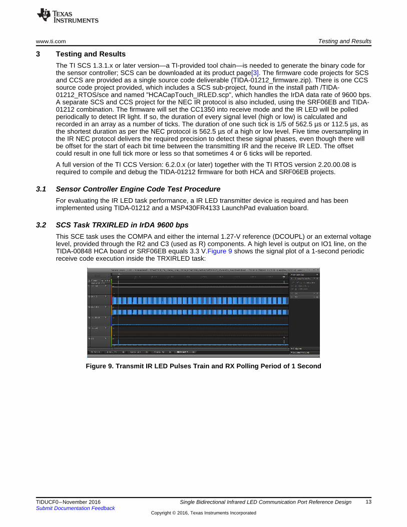
3.2 SCS Task TRXIRLED in IrDA 9600 bpsThis SCE task uses the COMPA and either the internal 1.27-V reference (DCOUPL) or an external voltagelevel, provided through the R2 and C3 (used as R) components. A high level is output on IO1 line, on theTIDA-00848 HCA board or SRF06EB equals 3.3 V.Figure 9 shows the signal plot of a 1-second periodicreceive code execution inside the TRXIRLED task:
Figure 9. Transmit IR LED Pulses Train and RX Polling Period of 1 Second
Single Bidirectional Infrared LED Communication Port Reference Design
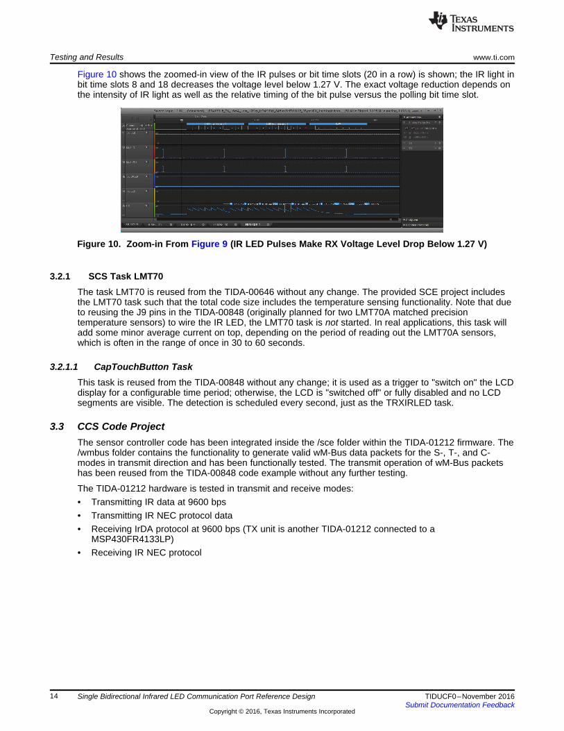
Figure 10 shows the zoomed-in view of the IR pulses or bit time slots (20 in a row) is shown; the IR light inbit time slots 8 and 18 decreases the voltage level below 1.27 V. The exact voltage reduction depends onthe intensity of IR light as well as the relative timing of the bit pulse versus the polling bit time slot.
Figure 10. Zoom-in From Figure 9 (IR LED Pulses Make RX Voltage Level Drop Below 1.27 V)
3.2.1 SCS Task LMT70The task LMT70 is reused from the TIDA-00646 without any change. The provided SCE project includesthe LMT70 task such that the total code size includes the temperature sensing functionality. Note that dueto reusing the J9 pins in the TIDA-00848 (originally planned for two LMT70A matched precisiontemperature sensors) to wire the IR LED, the LMT70 task is not started. In real applications, this task willadd some minor average current on top, depending on the period of reading out the LMT70A sensors,which is often in the range of once in 30 to 60 seconds.
3.2.1.1 CapTouchButton TaskThis task is reused from the TIDA-00848 without any change; it is used as a trigger to "switch on" the LCDdisplay for a configurable time period; otherwise, the LCD is "switched off" or fully disabled and no LCDsegments are visible. The detection is scheduled every second, just as the TRXIRLED task.
3.3 CCS Code ProjectThe sensor controller code has been integrated inside the /sce folder within the TIDA-01212 firmware. The/wmbus folder contains the functionality to generate valid wM-Bus data packets for the S-, T-, and C-modes in transmit direction and has been functionally tested. The transmit operation of wM-Bus packetshas been reused from the TIDA-00848 code example without any further testing.
The TIDA-01212 hardware is tested in transmit and receive modes:• Transmitting IR data at 9600 bps• Transmitting IR NEC protocol data• Receiving IrDA protocol at 9600 bps (TX unit is another TIDA-01212 connected to a
Single Bidirectional Infrared LED Communication Port Reference Design
3.4 Sensor Controller Task for NEC IR Protocol DetectionThe state.irlightDetected variable at the bottom graph is representing the IR LED incoming event.
Figure 11. IR Input Signal From TV RC Using NEC IR Protocol
The IR transmitted signal from an off the shelf Tevion remote control (RC) has been captured in Figure 11,where the Key "1" of the Tevion RC gets detected and decoded as 32 bits in irSIG[2-33]. The initial twoirSIG[0:1] array elements hold the 79 timer ticks of 112.5 µs for the HIGH period (preamble of 9 ms) andthe 41 ticks each for the LOW period of 4.5 ms following the preamble. Note that due to phase differencebetween the RC (transmitter) and the receiver (device under test), the number of ticks for the preambleand LOW phase afterwards will vary around 79 and 40 with ±1 tick mostly. The RC Key "1" is coded in thethird byte irSIG[18-25] as "1000 0000", and the same value is transmitted inverted, as seen in irSIG[26-33]as "0111 1111". Here a plot of Key 1 with two I/Os (TX and RX_ENB) is shown; note also that the lastpulse to the right is the "end of message" burst.
Figure 12. RX_ENB is the Analog Signal Input to COMPA (Using an Internal Reference ofDCOUPL = 1.27 V)
Single Bidirectional Infrared LED Communication Port Reference Design
The preamble and the following low level phase can be easily recognized within the RX_ENB (blue line inFigure 13) with the time measured at approximately 4.5 ms.
Figure 13. Timings for IR From TVR Using NEC IR Protocol, Preamble, Low Phase, and First Bits
In Figure 14, the timing of the logical "0" as per the NEC IR protocol has been captured and measured.
Figure 14. Timing of Logical "0" as per NEC IR Protocol
Finally, the logical "1" of the protocol is shown in Figure 15, consisting of a HIGH phase and three timeslonger LOW phase with a total duration of 2.25 ms.
Figure 15. Logical "1" Timing as per NEC IR Protocol
Single Bidirectional Infrared LED Communication Port Reference Design
3.5 IR LED Transmission in NEC IR ProtocolThe transmit operation of the TIDA-01212 has been tested using the CCS project. Only DIO5, DIO6, andDIO7 have the high driving strength of 8 mA, which must be set in the application code immediately afterthe scifInit() function call with this CC13xx DriverLib function:• IOCIODrvStrengthSet(IOID_6, IOC_CURRENT_8MA, PIN_DRVSTR_MAX);
The effect of this driverLib function call was successfully verified on one TIDA-01212, where almost 0.5 Vof higher output voltage at the DIO5 pin during IR LED transmission was measured.
3.6 TIDA-01212 Current ConsumptionThe power consumption of the TIDA-01212 was measured with an Agilent N6781A 2 quadrant source ormeasure unit for battery drain analysis. The average current drawn is 1.731 µA, as reported in the field"Avg" in Figure 16.
Single Bidirectional Infrared LED Communication Port Reference Design
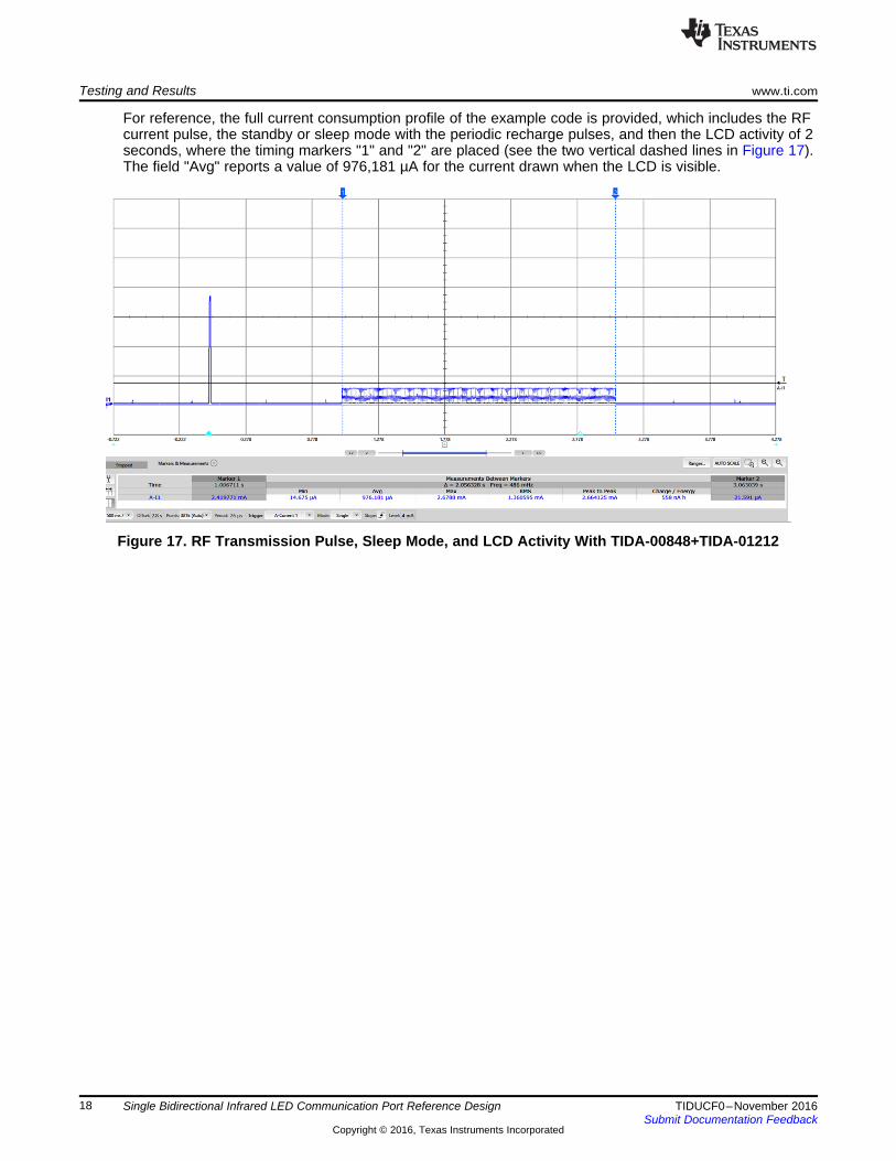
For reference, the full current consumption profile of the example code is provided, which includes the RFcurrent pulse, the standby or sleep mode with the periodic recharge pulses, and then the LCD activity of 2seconds, where the timing markers "1" and "2" are placed (see the two vertical dashed lines in Figure 17).The field "Avg" reports a value of 976,181 µA for the current drawn when the LCD is visible.
Figure 17. RF Transmission Pulse, Sleep Mode, and LCD Activity With TIDA-00848+TIDA-01212
Single Bidirectional Infrared LED Communication Port Reference Design
4 Design Files
4.1 SchematicsTo download the schematics, see the design files at TIDA-01212.
4.2 Bill of MaterialsTo download the bill of materials (BOM), see the design files at TIDA-01212.
4.3 PCB Layout Recommendations
4.3.1 Layout PrintsTo download the layer plots, see the design files at TIDA-01212.
4.4 Altium ProjectTo download the Altium project files, see the design files at TIDA-01212.
4.5 Gerber FilesTo download the Gerber files, see the design files at TIDA-01212.
4.6 Assembly DrawingsTo download the assembly drawings, see the design files at TIDA-01212.
5 Software FilesTo download the software files, see the design files at TIDA-01212.
6 Related Documentation
1. Infrared Data Association Serial Infrared Physical Layer Specification version 1.4 (May 30th, 2001)2. Texas Instruments, Reference Design for Segment LCD Control Using GPIO Pins to Increase System
Flexibility, TIDA-00848 Design Guide (TIDUBQ7)3. Texas Instruments, Sensor Controller Studio (http://www.ti.com/tool/sensor-controller-studio)4. Vishay Semiconductors, Infrared Data Communication According to IrDA® Standard Part 1: Physical
Layer, Doc.#: 82513, Rev 1.4, 20-Sep-065. Vishay Semiconductors, High Power Infrared Emitting Diode, 890 nm, GaAlAs / Double Hetero,
TSPF6200 Datasheet, Doc.#: 82425, Rev. 1.26. Mitsubishi Electric Research Laboratories, TR2003-35, July 2003 (http://www.merl.com)7. Altium, NEC Infrared Transmission Protocol, NEC IR protocol8. IEC 62056-21 Specification, Electricity metering – Data exchange for meter reading, tariff and load
control – Part 21: Direct local data exchange9. Texas Instruments, MSP430FR4133LP Product Page (http://www.ti.com/tool/msp-exp430fr4133)10. Vishay Semiconductors, TFBS4650 IRDA Module SIR Transceiver Product Page
(http://www.vishay.com/product?docid=84672)
6.1 TrademarksAll trademarks are the property of their respective owners.
Single Bidirectional Infrared LED Communication Port Reference Design
7 Terminology
HCA— Heat cost allocatorsBattery-powered electronic devices, used to capture the proportionate thermal output of radiators inconsumer units, popular or mandatory in many European countries
IrDA PHY— Infrared Data Association Serial Infrared Physical Layer Specification
8 About the AuthorMILEN STEFANOV (M.Sc.E.E) is a system engineer at TI, working in the Grid Infrastructure field and anexpert in RF communication technologies and metering applications. After graduating, he spent 5 years asa research assistant at the University of Chemnitz (TUC) and 3.5 years in the semiconductor industry inhigh-speed optical and wired communications as a system engineer. He joined TI in 2003 to become aWi-Fi expert and support TI’s Wi-Fi products at major OEMs; since 2010, he has focused on metering andsub-1GHz RF solutions for the European Grid Infrastructure market. Mr. Stefanov has published multiplearticles on wM-Bus technology in Europe and presented technical papers at the Wireless Congress andSmart Home & Metering summits in Munich.
Texas Instruments Incorporated (‘TI”) reference designs are solely intended to assist designers (“Designer(s)”) who are developing systemsthat incorporate TI products. TI has not conducted any testing other than that specifically described in the published documentation for aparticular reference design.TI’s provision of reference designs and any other technical, applications or design advice, quality characterization, reliability data or otherinformation or services does not expand or otherwise alter TI’s applicable published warranties or warranty disclaimers for TI products, andno additional obligations or liabilities arise from TI providing such reference designs or other items.TI reserves the right to make corrections, enhancements, improvements and other changes to its reference designs and other items.Designer understands and agrees that Designer remains responsible for using its independent analysis, evaluation and judgment indesigning Designer’s systems and products, and has full and exclusive responsibility to assure the safety of its products and compliance ofits products (and of all TI products used in or for such Designer’s products) with all applicable regulations, laws and other applicablerequirements. Designer represents that, with respect to its applications, it has all the necessary expertise to create and implementsafeguards that (1) anticipate dangerous consequences of failures, (2) monitor failures and their consequences, and (3) lessen thelikelihood of failures that might cause harm and take appropriate actions. Designer agrees that prior to using or distributing any systemsthat include TI products, Designer will thoroughly test such systems and the functionality of such TI products as used in such systems.Designer may not use any TI products in life-critical medical equipment unless authorized officers of the parties have executed a specialcontract specifically governing such use. Life-critical medical equipment is medical equipment where failure of such equipment would causeserious bodily injury or death (e.g., life support, pacemakers, defibrillators, heart pumps, neurostimulators, and implantables). Suchequipment includes, without limitation, all medical devices identified by the U.S. Food and Drug Administration as Class III devices andequivalent classifications outside the U.S.Designers are authorized to use, copy and modify any individual TI reference design only in connection with the development of endproducts that include the TI product(s) identified in that reference design. HOWEVER, NO OTHER LICENSE, EXPRESS OR IMPLIED, BYESTOPPEL OR OTHERWISE TO ANY OTHER TI INTELLECTUAL PROPERTY RIGHT, AND NO LICENSE TO ANY TECHNOLOGY ORINTELLECTUAL PROPERTY RIGHT OF TI OR ANY THIRD PARTY IS GRANTED HEREIN, including but not limited to any patent right,copyright, mask work right, or other intellectual property right relating to any combination, machine, or process in which TI products orservices are used. Information published by TI regarding third-party products or services does not constitute a license to use such productsor services, or a warranty or endorsement thereof. Use of the reference design or other items described above may require a license from athird party under the patents or other intellectual property of the third party, or a license from TI under the patents or other intellectualproperty of TI.TI REFERENCE DESIGNS AND OTHER ITEMS DESCRIBED ABOVE ARE PROVIDED “AS IS” AND WITH ALL FAULTS. TI DISCLAIMSALL OTHER WARRANTIES OR REPRESENTATIONS, EXPRESS OR IMPLIED, REGARDING THE REFERENCE DESIGNS OR USE OFTHE REFERENCE DESIGNS, INCLUDING BUT NOT LIMITED TO ACCURACY OR COMPLETENESS, TITLE, ANY EPIDEMIC FAILUREWARRANTY AND ANY IMPLIED WARRANTIES OF MERCHANTABILITY, FITNESS FOR A PARTICULAR PURPOSE, AND NON-INFRINGEMENT OF ANY THIRD PARTY INTELLECTUAL PROPERTY RIGHTS.TI SHALL NOT BE LIABLE FOR AND SHALL NOT DEFEND OR INDEMNIFY DESIGNERS AGAINST ANY CLAIM, INCLUDING BUT NOTLIMITED TO ANY INFRINGEMENT CLAIM THAT RELATES TO OR IS BASED ON ANY COMBINATION OF PRODUCTS ASDESCRIBED IN A TI REFERENCE DESIGN OR OTHERWISE. IN NO EVENT SHALL TI BE LIABLE FOR ANY ACTUAL, DIRECT,SPECIAL, COLLATERAL, INDIRECT, PUNITIVE, INCIDENTAL, CONSEQUENTIAL OR EXEMPLARY DAMAGES IN CONNECTION WITHOR ARISING OUT OF THE REFERENCE DESIGNS OR USE OF THE REFERENCE DESIGNS, AND REGARDLESS OF WHETHER TIHAS BEEN ADVISED OF THE POSSIBILITY OF SUCH DAMAGES.TI’s standard terms of sale for semiconductor products (http://www.ti.com/sc/docs/stdterms.htm) apply to the sale of packaged integratedcircuit products. Additional terms may apply to the use or sale of other types of TI products and services.Designer will fully indemnify TI and its representatives against any damages, costs, losses, and/or liabilities arising out of Designer’s non-compliance with the terms and provisions of this Notice.IMPORTANT NOTICE


![Arca LED Gen5 [ACL] selux...Project: Type: Qty: Date: Customer: Date: Series ACL Arca LED Light Engine 5G1350 Single LED 24W/2520lm 5G2800 2 Double LED 100W/9900lm 5G1800 2 Single](https://static.documents.pub/doc/80x56/5f92c223e2beb91e807add15/arca-led-gen5-acl-selux-project-type-qty-date-customer-date-series-acl.jpg)

