Rev. 12-10 Installation Instructions SERIES 360 Single Hung Windows Page 2: Opening Preparation and Wood Buck Installation and Figure 1 Page 3-5: Installation Instructions for Series 360 WINDOWS Page 6: Figure 2: Installation type “A” Page 7: Figure 3: Installation type “B” Page 8: Figure 4: Installation type “C” Page 9: Figure 5: Installation type “D” and Figure 6 Page 10-12: Operable Sash Removal Page 12: Fixed Sash Removable Page 13: Figures 8 and 9 NOTE: Read instructions completely before attempting any installation. These instructions are provided as a general guide in the installation of our Series 360 products. Applicable Miami-Dade County Product Approvals (or TDI Approvals in Texas) should be used in conjunction with these instructions. Only experienced installers familiar with these or similar products should attempt to install these units. Refer to CGI Series 360 Design Guide for further information & details pertaining to these products. Incorrect installations could void the warranty. Technical support is available by contacting CGI at 305-593-6590 (Miami) or 1-800-442-9042 www.cgiwindows.com
Transcript
Rev. 12-10
I n s t a l l a t i o n I n s t r u c t i o n s
S E R I E S 3 6 0
Single Hung Windows
Page 2: Opening Preparation and Wood Buck Installation and Figure 1
Page 3-5: Installation Instructions for Series 360 WINDOWS Page 6: Figure 2: Installation type “A” Page 7: Figure 3: Installation type “B” Page 8: Figure 4: Installation type “C” Page 9: Figure 5: Installation type “D” and Figure 6 Page 10-12: Operable Sash Removal Page 12: Fixed Sash Removable Page 13: Figures 8 and 9
NOTE: Read instructions completely before attempting any installation.
These instructions are provided as a general guide in the installation of our Series 360 products. Applicable Miami-Dade County Product Approvals (or TDI Approvals in Texas) should be used in
conjunction with these instructions. Only experienced installers familiar with these or similar products should attempt to install these units. Refer to CGI Series 360 Design Guide for further
information & details pertaining to these products. Incorrect installations could void the warranty.
Technical support is available by contacting CGI at 305-593-6590 (Miami) or 1-800-442-9042
www.cgiwindows.com
2
OPENING PREPARATION AND WOOD BUCK INSTALLATION
1. Make sure that masonry opening (or rough opening on stud construction) is made to within tolerance, level and plumb. Verify by measuring at each end and every 24” (vertically and horizontally). Make any corrections required to openings. Bucks must be set on a smooth and flat surface. Remove or chip away any concrete, which protrudes from the face of the opening prior to setting bucks. Make sure ends of masonry opening are square and not rounded at corners. Chip concrete if necessary.
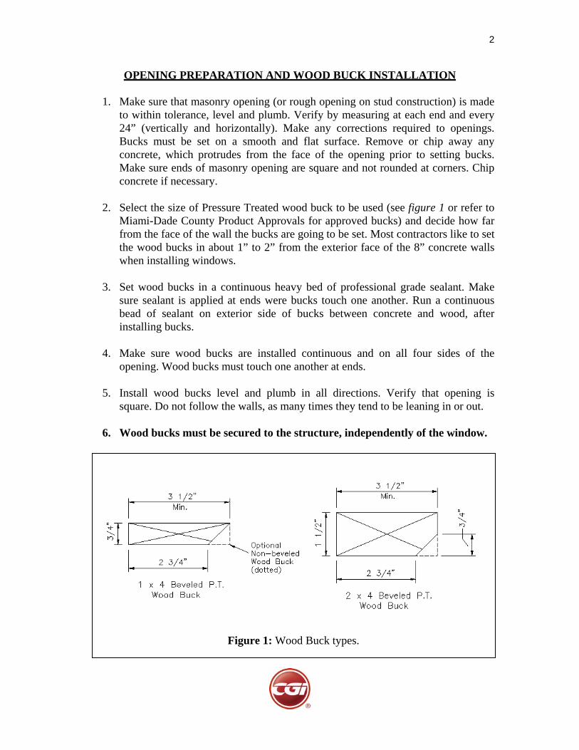
2. Select the size of Pressure Treated wood buck to be used (see figure 1 or refer to
Miami-Dade County Product Approvals for approved bucks) and decide how far from the face of the wall the bucks are going to be set. Most contractors like to set the wood bucks in about 1” to 2” from the exterior face of the 8” concrete walls when installing windows.
3. Set wood bucks in a continuous heavy bed of professional grade sealant. Make
sure sealant is applied at ends were bucks touch one another. Run a continuous bead of sealant on exterior side of bucks between concrete and wood, after installing bucks.
4. Make sure wood bucks are installed continuous and on all four sides of the
opening. Wood bucks must touch one another at ends.
5. Install wood bucks level and plumb in all directions. Verify that opening is square. Do not follow the walls, as many times they tend to be leaning in or out.
6. Wood bucks must be secured to the structure, independently of the window.
Figure 1: Wood Buck types.
3
SERIES 360 S/H WINDOWS - INSTALLATION INSTRUCTIONS
1. Check window opening for correct size. If the opening is incorrect, have it fixed. Never attempt to force a window into a small opening or install a window into an oversized opening.
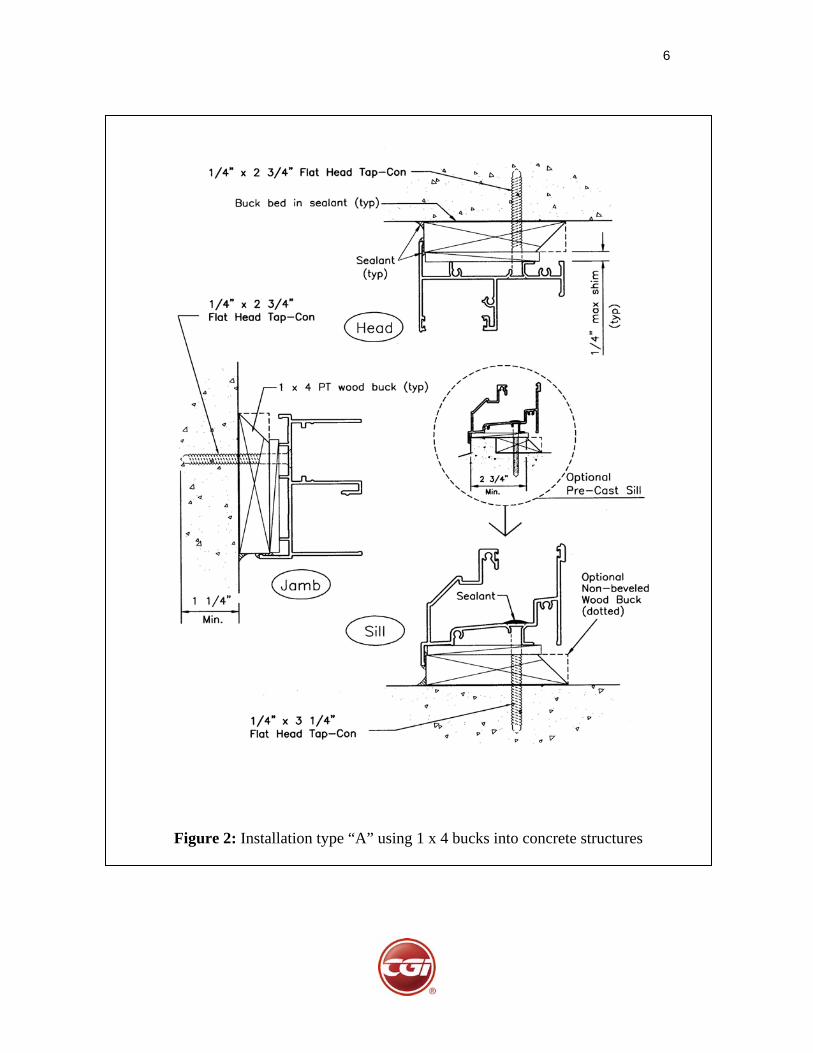
2. Make sure wood bucks are of the correct size and type for the installation method being used (see figures 2, 3, 4 or 5 - Installations Types A, B, C or D). The bucks must be properly bed in sealant and securely attached to structure. Wood bucks should not be separated at corners. Verify that wood bucks are plumb, level and square.
3. Clean window flange and apply a generous amount of professional grade sealant / caulking material to flange at full perimeter. Make sure the sealant is compatible and will adhere to aluminum and wood.
4. Stand window upright and open sash. Make sure the window is standing upright, as if it were installed. If the window is lying flat, upside down or on its side, the balance will not have enough counterweight from the sash and the sash will open very quickly. This may cause injury or damage to the window. Once the window is properly opened, install window from the outside on to the wood bucks.
5. Temporarily secure window frame using installation screws as selected from the Miami-Dade County Product Approvals (TDI Approvals in Texas) for your specific application (see figures 2 – 5). To simplify the pre-installation process, you may want to use a smaller temporary screw such as a #12 Flat Head Sheet Metal Screw and only penetrate the wood. Shim every installation screw snugly (shim space should not exceed ¼”). Temporarily secure the window with one screw at each end of the head member and one screw on each jamb (use the bottom most screw hole on the jambs). Make sure window operate correctly. Make sure window is plumb, level and square. Caution: Any window, which is forced into an opening and racked or twisted, can eventually cause glass breakage.
6. Once the window is correctly set, finish installing with the proper installation screws. If temporary #12 screws were used, replace those with the correct screws. Every hole must have a screw. In order to access the installation holes on the jamb above the vent, you will need to remove the balance covers. To do this, close and lock the window. Gently remove the vinyl balance covers starting from the top and pull out of the jamb towards the opposite jamb (see figure 6). These covers have a slight snap engagement with the jamb that allows them to be easily removed. Install the installation screws at this area, and replace the balance covers. To replace the balance covers, repeat the same operation as when removing, but in reverse order. This is done by inserting the cover at the bottom of the jamb first and tucking the cover behind and below the sash about 1/2".
4
You may need to pinch the cover snap legs in when you first start to insert the cover into the jamb. Slowly snap the cover all the way up the jamb until the top snaps in. Make sure the covers are pulled tight up on the jamb and touch the head frame member.
7. In some very rare cases, where very large windows are used or when windows are installed into very high windload area (high PSF requirements), additional installation screws may be required. CGI only provides a standard installation hole pattern, called “CGI Standard Hole Pattern”. Refer to the Anchor Charts found in the Miami-Dade County product approvals to see if the window being installed meets the PSF requirement with the standard hole pattern. If it does not meet it, additional anchor holes need to be drilled in the field as per the Product Approval.
8. Seal the screw heads on the sill with 100% silicone rubber. You may want to slightly back out the screws, apply some silicone all around under the screw head and then reinsert the screws.
9. If installing mullion tubes between S/H windows, make sure tubes are properly aligned on the window. The standard Series 360 S/H Mullions (1” x 4” x 1/8” thk.) do not require end clips. The proper mullion length is 1” smaller than the outside window dimension, or the same size as the interior window dimension. If you are mulling the Single Hung window to a Series 238 Window (Fixed, Designer Fixed or Casement), the mullions will require end clips that attach to the structure. Refer to the Series 238 installation instructions for the attachment of these mullions.
10. If the mullion being installed is long or the windows being mulled are large or the opening is located in a high windload area, additional installation holes may be required on each side of mullion, at the window sill and head member. Remember that these mullions do not have independent clips, so their anchorage is transferred to the window frames. The CGI Standard Hole Pattern includes one installation hole at each end of the sill and head members. Certain installations will require two or three screws on each side of the mullion. Refer to the Mullion Design Load Capacity Charts and the Mullion details in the Product Approvals to see if additional screws are required. These additional screw holes must be field drilled.
11. Make sure there is no daylight between wood buck and window flange. If any exist or as a precautionary step, apply additional sealant from the outside at this joint.
12. Check window for leakage, especially on the frame joints. Although not normal, it may be necessary to reseal frame corners after installing. The factory applied sealant may get damaged during transport of the window due to racking.
5
13. Perform a last check of the window operation. If the window is not opening properly, make sure the heads of the jamb installation screws are tight against the aluminum and not sticking out. Also, make sure there is no debris along the jambs (where the sash slides on) or inside the sill. Lastly, make sure the frame sill is not bowed/twisted and preventing the egress locks from self-locking when closing.
INSTALLATION HINT: If the window does not close properly and evenly, then re-check plumbness, level and squareness. Also make sure that the sill is not bowed at the center and the frame members are not twisted. RECOMMENDED INSTALLATION SCREWS (refer to Product Approvals) : Window attachment to structure
Based on installation type used. Refer to figures 2, 3, 4 or 5 in these instructions for the minimum screw size recommended in installations type A, B, C or D. Also, refer to Miami-Dade County product Approvals.
Window to mullion screws #14 x 1” Lg. Flat Head Teks Stainless Steel or #14 x 3/4" “B” Point SMS Stainless Steel
6
Figure 2: Installation type “A” using 1 x 4 bucks into concrete structures
7
Figure 3: Installation type “B” using 2 x 4 bucks into concrete structures
8
Figure 4: Installation type “C” using 1 x 4 bucks into wood structures
9
Figure 5: Installation type “D” using 2 x 4 bucks into wood structures
Figure 6: Removal of balance cover from jambs
10
SERIES 360 S/H WINDOWS – OPERABLE SASH REMOVAL Removal of the operable sash is rarely required on S/H windows. The sash is sometimes removed to replace the balances, to clean the exterior face of the sash or in the case of the CGI Series 360 S/H, the operable sash needs to be taken out in order to remove the fixed upper sash. There are two different types of balances attachment methods used on the Series 360 S/H windows and the removal of the sash depends on the balance attachment method used. Most windows use the patented CGI sash carrier system along with a Block & Tackle Tilt balance or sometimes a Spiral Balance (on very heavy sash). This system allows the balance to be attached to the carrier and the sash can be removed without disconnecting the balance. Although rare, extremely larger and heavy vent windows may use a Heavy Duty spiral balance, attached directly to the sash. This system requires the balance to be disconnected when removing the sash. To determine the balance attachment method of a specific window, open the sash about 12” and look under the sash at the jambs (ends). If you see a zinc (silver) part with a hole that sticks out from under the sash (see figure 7 below), then this window uses the CGI sash carrier system. Following are instructions for removal of sash using each type of balance attachment method: CGI patented sash carrier system
1. Open the sash about 8 inches. Look under the sash and you will see the zinc carrier system sticking out about 1/2" from the bottom of the sash on each jamb. You will also see a round hole on each carrier and an oval hole on each frame jamb. Once you are familiar with these holes and their location, close the window.
2. With the window closed, remove the balance covers on each jamb (see figure 6). To do this, gently remove the plastic balance covers starting from the top and pull out of the jamb towards the opposite jamb.
3. Slowly lift the sash open until the round holes on the carrier and the oval hole in the jamb align. Be careful not to rack the sash at the top. Remember that the balance covers, which also serve as top guides, are no longer there.
4. Insert a 3/16” positive locking pin (or similar pin) from the carrier hole into the jamb hole. If a locking pin is not available, insert a #10 Sheet Metal Screw
Figure 7: CGI Sash Carrier
11
through both holes and screw it into the wood buck. As a last solution, insert a screwdriver through the holes. Be careful if using a screwdriver because it can fall out and release the carrier. This can cause injury or damage to the window.
5. At this point the carrier is locked in place. You will need to lift the sash up by hand, without the benefit of the balance. If the sash is heavy, get assistance from someone else. Lift the sash up about another 4 to 6 inches from this point. Remove the sash by inserting the sash all the way into one jamb, swinging the opposite side towards you and removing from the frame.
6. If you are replacing the balance, do so now. Carefully, disengage the balance from the carrier. This is done by grasping the end of the balance with locking pliers or a hook, lowering the balance away from the carrier and slowly allowing the balance to retract. Be very careful, because if the balance slips away from the pliers or hook, it may retract violently and could cause injury. Unscrew the balance, replace and reattach the balance to the carrier.
7. To reinstall the sash, reinsert the sash into one jamb (above the carrier location), swing the other side to align with the opposite jamb and center the sash on the jambs. Slowly lower the sash until both sides engage the carrier. Look from below and make sure that the distance between the carriers and sash is the same on both sides.
8. Remove the locking pins from the carrier, slowly lower the sash until closed and reinstall the balance covers.
Heavy Duty Spiral balance connected directly to sash
1. With the window closed, remove the bottom guides located inside the operable sash. Also remove the balance covers on each jamb. To do this, gently remove the balance covers starting from the top and pull out of the jamb towards the opposite jamb (see figure 6).
2. Slowly, open sash up about 80%.
3. Have someone hold the sash in place. Using a Spiral balance removal tool, disconnect each spiral balance from the sash clips. Be careful when doing this, as the balance will want to rotate, pull up and retract.
4. Slowly, remove the sash by inserting the sash all the way into one jamb, swinging the opposite side towards you and removing from the frame.
12
5. To reinstall the sash, reinsert the sash (at the same upper most point as removed) into one jamb, swing the other side to align with the opposite jamb and center the sash on the jambs.
6. Using the balance tool, grab the balance rod, rotate as required (consult CGI for turns necessary depending on balance length and sash weight) and reattach to the sash clips.
7. Lower sash slowly, reinstall balance covers and reattach the bottom guides.
SERIES 360 S/H WINDOWS – FIXED SASH REMOVAL Removal of the fixed sash is only required when replacing the fixed sash or when reglazing the fixed sash on a worktable or sawhorses. Although the sash can be reglazed while in place, proper reglazing should be done with the sash flat on a work surface.
1. First, you will need to remove the operable sash. Refer to instructions for “Operable Sash Removal” beginning on page 10. Once the operable sash is removed, go on to step 2.
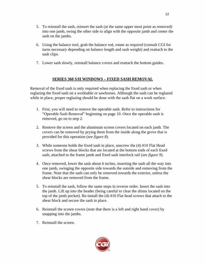
2. Remove the screen and the aluminum screen covers located on each jamb. The covers can be removed by prying them from the inside along the grove that is provided for this operation (see figure 8).
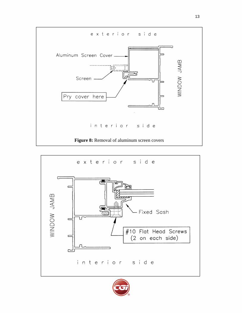
3. While someone holds the fixed sash in place, unscrew the (4) #10 Flat Head screws from the shear blocks that are located at the bottom ends of each fixed sash, attached to the frame jamb and fixed sash interlock rail (see figure 9).
4. Once removed, lower the sash about 6 inches, inserting the sash all the way into one jamb, swinging the opposite side towards the outside and removing from the frame. Note that the sash can only be removed towards the exterior, unless the shear blocks are removed from the frame.
5. To reinstall the sash, follow the same steps in reverse order. Insert the sash into the jamb. Lift up into the header (being careful to clear the shims located on the top of the jamb pocket). Re-install the (4) #10 Flat head screws that attach to the shear block and secure the sash in place.
6. Reinstall the screen covers (note that there is a left and right hand cover) by snapping into the jambs.