ARTICLE Received 9 Mar 2016 | Accepted 22 Jun 2016 | Published 25 Jul 2016 Single microwave-photon detector using an artificial L-type three-level system Kunihiro Inomata 1, *, Zhirong Lin 1, *, Kazuki Koshino 2 , William D. Oliver 3,4 , Jaw-Shen Tsai 1,5 , Tsuyoshi Yamamoto 6 & Yasunobu Nakamura 1,7 Single-photon detection is a requisite technique in quantum-optics experiments in both the optical and the microwave domains. However, the energy of microwave quanta are four to five orders of magnitude less than their optical counterpart, making the efficient detection of single microwave photons extremely challenging. Here we demonstrate the detection of a single microwave photon propagating through a waveguide. The detector is implemented with an impedance-matched artificial L system comprising the dressed states of a driven superconducting qubit coupled to a microwave resonator. Each signal photon deterministi- cally induces a Raman transition in the L system and excites the qubit. The subsequent dispersive readout of the qubit produces a discrete ‘click’. We attain a high single-photon- detection efficiency of 0.66 ± 0.06 with a low dark-count probability of 0.014 ± 0.001 and a reset time of B400 ns. This detector can be exploited for various applications in quantum sensing, quantum communication and quantum information processing. DOI: 10.1038/ncomms12303 OPEN 1 RIKEN Center for Emergent Matter Science (CEMS), Wako 351-0198, Saitama, Japan. 2 College of Liberal Arts and Sciences, Tokyo Medical and Dental University, Ichikawa 272-0827, Chiba, Japan. 3 MIT Lincoln Laboratory, Lexington, Massachusetts 02420, USA. 4 Departent of Physics, Massachusetts Institute of Technology, Cambridge, Massachusetts 02139, USA. 5 Department of Physics, Tokyo University of Science, Shinjuku-ku, Tokyo 162-8601, Japan. 6 NEC IoT Device Research Laboratories, Tsukuba 305-8501, Ibaraki, Japan. 7 Research Center for Advanced Science and Technology (RCAST), The University of Tokyo, Meguro-ku, Tokyo 153-8904, Japan. *These authors contributed equally to this work. Correspondence and requests for materials should be addressed to K.I. (email: [email protected]). NATURE COMMUNICATIONS | 7:12303 | DOI: 10.1038/ncomms12303 | www.nature.com/naturecommunications 1
Transcript
ARTICLE
Received 9 Mar 2016 | Accepted 22 Jun 2016 | Published 25 Jul 2016
Single microwave-photon detector using anartificial L-type three-level systemKunihiro Inomata1,*, Zhirong Lin1,*, Kazuki Koshino2, William D. Oliver3,4, Jaw-Shen Tsai1,5, Tsuyoshi Yamamoto6
& Yasunobu Nakamura1,7
Single-photon detection is a requisite technique in quantum-optics experiments in both the
optical and the microwave domains. However, the energy of microwave quanta are four to five
orders of magnitude less than their optical counterpart, making the efficient detection of
single microwave photons extremely challenging. Here we demonstrate the detection of a
single microwave photon propagating through a waveguide. The detector is implemented
with an impedance-matched artificial L system comprising the dressed states of a driven
superconducting qubit coupled to a microwave resonator. Each signal photon deterministi-
cally induces a Raman transition in the L system and excites the qubit. The subsequent
dispersive readout of the qubit produces a discrete ‘click’. We attain a high single-photon-
detection efficiency of 0.66±0.06 with a low dark-count probability of 0.014±0.001 and a
reset time of B400 ns. This detector can be exploited for various applications in quantum
sensing, quantum communication and quantum information processing.
DOI: 10.1038/ncomms12303 OPEN
1 RIKEN Center for Emergent Matter Science (CEMS), Wako 351-0198, Saitama, Japan. 2 College of Liberal Arts and Sciences, Tokyo Medical and DentalUniversity, Ichikawa 272-0827, Chiba, Japan. 3 MIT Lincoln Laboratory, Lexington, Massachusetts 02420, USA. 4 Departent of Physics, MassachusettsInstitute of Technology, Cambridge, Massachusetts 02139, USA. 5 Department of Physics, Tokyo University of Science, Shinjuku-ku, Tokyo 162-8601, Japan.6 NEC IoT Device Research Laboratories, Tsukuba 305-8501, Ibaraki, Japan. 7 Research Center for Advanced Science and Technology (RCAST), The Universityof Tokyo, Meguro-ku, Tokyo 153-8904, Japan. * These authors contributed equally to this work. Correspondence and requests for materials should beaddressed to K.I. (email: [email protected]).
Single-photon detection is essential to many quantum-opticsexperiments, enabling photon counting and its statisticaland correlational analyses1. It is also an indispensable tool
in many protocols for quantum communication and quantuminformation processing2–5. In the optical domain, various kindsof single-photon detectors are commercially available andcommonly used1,6. However, despite the latest developments innearly-quantum-limited amplification7,8 and homodynemeasurement for extracting microwave photon statistics9, thedetection of a single microwave photon in an itinerant moderemains a challenging task due to its correspondingly smallenergy. Meanwhile, the demand for such detectors is rapidlyincreasing, driven by applications involving both microwave andhybrid optical-microwave quantum systems. In this article wedemonstrate an efficient and practical single microwave-photondetector based on the deterministic switching in an artificialL-type three-level system implemented using the dressed states of adriven superconducting quantum circuit. The detector operates in atime-gated mode and features a high quantum efficiency 0.66±0.06,a low dark-count probability 0.014±0.001, a bandwidthB2p� 16 MHz, and a fast reset time B400 ns. It can be readilyintegrated with other components for microwave quantum optics.
Our detection scheme carries several advantages compared withprevious proposals. It uses coherent quantum dynamics, whichminimizes energy dissipation on detection and allows for rapidresetting with a resonant drive, in contrast to schemes that involveswitching from metastable states of a current-biased Josephsonjunction into the finite voltage state10–12. Moreover, our detection
scheme does not require any temporal shaping of the inputphotons, nor precise time-dependent control of system parametersadapted to the temporal mode of the input photons, in contrast tothe photon-capturing experiments13–15. Temporal mode mismatchof the photons also limits the maximum efficiency in the recentlydemonstrated single-photon detection using a transmon qubit in athree-dimensional (3D) cavity16. Finally, our scheme also achievesa high efficiency without cascading many devices10,17.
The operating principle of the detector fully employs theelegance of waveguide quantum electrodynamics, which hasrecently attracted significant attention in various contextssurrounding photonic quantum information processing18–21.When electromagnetic waves are confined and propagate in aone-dimensional (1D) mode, their interaction with a quantumemitter/scatterer is substantially simplified and enhancedcompared with 3D cases. These advantages result from thenatural spatial-mode matching of the emitter/scatterer with a 1Dmode and its resulting enhancement of quantum interferenceeffects. Remarkable examples are the perfect extinction ofmicrowave transmission for an artificial atom coupled to a 1Dtransmission line22,23, the photon-mediated interaction betweentwo remote atoms coupled to a 1D transmission line24, and theperfect absorption— and thus ‘impedance matching’— of a L-typethree-level system terminating a 1D transmission line25,26. In thelatter system, the incident photon deterministically induces aRaman transition, which switches the state of the L system25,27.This effect has recently been demonstrated in both the microwaveand optical domains26,28, indicating its potential for photon
Drive port
Signal port
Pump port
a
b
Drive
Signal
Signal
ReadoutDetectionInitialization
c
|e,0⟩
|g,1⟩ |e,1⟩
ωr
ωge
ωr– 2χ|4⟩~
|2⟩~
|1⟩~
~|3⟩
td
Pd
trisetrd
ts
~ ~~ ~
~ ~
tpump
ωd
ωs
ωrd
ωpump
|g,0⟩|e,0⟩
|g,1⟩ |e,1⟩
tdelay1
tdelay2
ns
Ppum
p
nrd
|g,0⟩
λ/2 re
sonator + flu
x qubit
Impedance matched Λ system Drive
Sample chip
Parametric phase-locked oscilla
tor
Pump
Circulators
Figure 1 | Experimental set-up and pulse sequence. (a) Image of the sample chip containing a flux qubit and a superconducting microwave resonator
coupled capacitively and operated in the dispersive regime. For certain proper conditions of the qubit drive, the coupled system functions as an impedance-
matched L-type three-level system. (b) Schematic of the itinerant microwave-photon detector consisting of the coupled system and connected to a
parametric phase-locked oscillator (PPLO) via three circulators in series. The circuit has three input ports: signal, qubit drive, and pump for the PPLO.
(c) Energy-level diagram of the coupled system and the pulse sequence for single-photon detection. The system is first prepared in the ground state.
During the detection stage, we concurrently apply the drive and signal pulses. The drive is parameterized to fulfil the impedance-matched condition such
that a signal photon (blue arrow) induces a deterministic Raman transition. A downconverted photon (green arrow) is emitted in the process and
discarded. In the readout stage, we detect the qubit excited state nondestructively by sending a qubit readout pulse. The qubit-state-dependent phase shift
in the reflected pulse is discriminated by the PPLO. Detailed parameters of the pulse sequence are provided in Methods.
detection29 as well as for implementing deterministic entanglinggates with photonic qubits30.
ResultsImplementation of a single microwave-photon detector. Ourdevice consists of a superconducting flux qubit capacitively and
dispersively coupled to a microwave resonator (Fig. 1b andref. 31; also see Supplementary Note 1 and Supplementary Fig. 1for the details of the device). With a proper choice of the qubitdrive frequency od and power Pd, the system functions as animpedance-matched L system with identical radiative decay ratesfrom its upper state to its two lower states (Fig. 1a)25,26. Thequbit–resonator coupled system is connected to a parametric
10.30
10.28
10.26
–85 –80 –75 –70 –85 –80 –75 –70
–85 –80 –75 –70
–85 –80 –75 –70
–85 –80 –75 –70
ωs/
2π (
GH
z)
Pd (dBm)
Pd (dBm)
0.5
0
η
1.0
0.60η
Pd (dBm)
10.30
10.28
10.26
e
–20 0| r | (dB)
10.30
10.25
10.20
10.30
10.25
10.20–70–75–80–85 –70–75–80–85
a
ωs/
2π (
GH
z)
10.30
10.28
10.26
Pd (dBm)
Pd (dBm)
10.30
10.28
10.26
Exp.
Calc.
b
–20 0| r | (dB)
0.60η
d
c
Figure 2 | Impedance matching and itinerant microwave-photon detection. (a) Amplitude of the reflection coefficient |r| of the input signal pulse with
mean photon number �ns�0:1 as a function of the qubit drive power Pd and the signal frequency os. The PPLO is not activated during this measurement.
The impedance-matched region is resolved (dark-blue point), where the input microwave photon is absorbed almost completely. In the inset, we also
observe another dip in |r|, corresponding to the Raman transition of j~1i ! j~3i ! j~2i. Microwave power levels stated in this article are referred to the value
at the corresponding ports on the sample chip. (b) Detection efficiency Z of an itinerant microwave photon. The efficiency reaches its maximum at the
impedance-matched point, where the Raman transition of j~1i ! j~4i ! j~2i takes place. (c,d) Theoretical predictions corresponding to a and b. (e) Cross-
sections of (b) (blue dots) and (d) (red dashed line) at os/2p¼ 10.268 GHz. The error bars are due to the uncertainty in the input power calibration (see
Supplementary Note 5 and Supplementary Fig. 5 for the details of the input power calibration).
phase-locked oscillator (PPLO), which enables fast andnon-destructive qubit readout (ref. 32; also see SupplementaryNotes 1 and 2, and Supplementary Fig. 2 for the details of thedevice and the experimental set-up).
Figure 1c shows the level structure of the qubit–resonatorsystem and the protocol for the single-photon detection. We labelthe energy levels |q, ni and their eigenfrequencies o|q,ni, whereq¼ {g, e} and n¼ {0, 1, ?}, respectively, denote the qubit stateand the photon number in the resonator. In the dispersivecoupling regime, the qubit–resonator interaction renormalizes theeigenfrequencies to yield o|g,ni ¼ nor and o|e,ni ¼ogeþ n(or� 2w),where oge and or are the renormalized frequencies of thequbit and the resonator, respectively, and w is the dispersivefrequency shift of the resonator due to its interaction with thequbit. Only the lowest four levels with n¼ 0 or 1 are relevanthere.
We prepare the system in its ground state |g, 0i (Fig. 1c,Initialization) and apply a drive pulse to the qubit (Fig. 1c,Detection). In a frame rotating at od, the level structure becomesnested, that is, o|g,0ioo|e,0ioo|e,1ioo|g,1i, for od in the rangeoge� 2woodooge (refs 25, 26). On the plateau of the drivepulse, the lower-two levels |g, 0i and |e, 0i (higher-two levels |g, 1iand |e, 1i) hybridize to form dressed states j~1i and j~2i (j~3i andj~4i). Under a proper choice of Pd, the two radiative decay ratesfrom j~4i (or j~3i) to the lowest-two levels become identical. Thus,an impedance-matched L system comprising j~1i, j~2i and j~4i(alternatively, j~1i, j~2i and j~3i) is realized. An incident singlemicrowave photon (Gaussian envelope, length ts), synchronouslyapplied with the drive pulse through the signal port and inresonance with the j~1i ! j~4i transition, deterministically inducesa Raman transition, j~1i ! j~4i ! j~2i, and is downconverted to aphoton at the j~4i ! j~2i transition frequency. This process isnecessarily accompanied by an excitation of the qubit.
Finally, we adiabatically switch off the qubit drive anddispersively read out the qubit state (Fig. 1c, Readout). We applya readout pulse with the frequency ord¼or� 2w¼o|e,1i �o|e,0ithrough the signal port, which, on reflection at the resonator,acquires a qubit-state-dependent phase shift of 0 or p. This phaseshift is detected by the PPLO with high fidelity: in the present set-up, the readout fidelity of the qubit is B0.9, which is primarilylimited by qubit relaxation before readout32.
Demonstration of single microwave-photon detection. We firstdetermine the operating point where the L system deterministi-cally absorbs a signal photon. We simultaneously apply a drivepulse of length td¼ 178 ns and a signal pulse of length ts¼ 85 ns,and proceed to measure the reflection coefficient |r| of the signalpulse as a function of the drive power Pd and the signal frequencyos (Fig. 2a). The signal pulse is in a weak coherent state withmean photon number �ns� 0:1. A pronounced dip with a depth ofo� 25 dB is observed in |r| at (Pd, os/2p)¼ (� 76 dBm,10.268 GHz), in close agreement with theory (Fig. 2c). The dipindicates a near-perfect absorption condition, that is, impedancematching, where the reflection of the input microwave photonvanishes due to destructive self-interference. Correspondingly, adeterministic Raman transition of j~1i ! j~4i ! j~2i is induced,and the qubit state is flipped.
To obtain a ‘click’ corresponding to single-photon detection,we read out the qubit state by using the PPLO immediately afterthe Raman transition. Before initiating readout, the drive pulse isturned off to suppress unwanted Raman transitions induced bythe readout pulse, for example, j~2i ! j~3i ! j~1i. We repeatedlyapply the pulse sequence in Fig. 1c 104 times and evaluate thesingle-photon-detection efficiency Z�P(|ei)/[1�P(0)], whereP(|ei) and P(0)� exp(� �ns) are the probabilities for the qubitbeing in the excited state and the signal pulse being in the vacuumstate, respectively. We emphasize that the detection efficiencyhere is defined with respect to the mean photon number in the
ts (ns)100
0200
0.5
1
η
0
0.5η
1.0
ns
0.01 0.1 1
3000
a
Exp.
Calc.
ts=34 ns
ts=85 ns
ts=189 ns
c
ns
0.01 0.1 1
10–1
1b
P (
|e⟩)
ts=34 ns
ts=85 ns
ts=189 ns
10–2
10–3
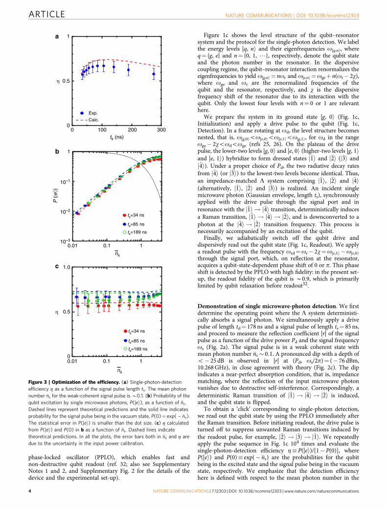
Figure 3 | Optimization of the efficiency. (a) Single-photon-detection
efficiency Z as a function of the signal pulse length ts. The mean photon
number �ns for the weak-coherent signal pulse is B0.1. (b) Probability of the
qubit excitation by single microwave photons, P(|ei), as a function of �ns.
Dashed lines represent theoretical predictions and the solid line indicates
probability for the signal pulse being in the vacuum state, P(0)¼ exp(� �ns).
The statistical error in P(|ei) is smaller than the dot size. (c) Z calculated
from P(|ei) and P(0) in b as a function of �ns. Dashed lines indicate
theoretical predictions. In all the plots, the error bars both in �ns and Z are
due to the uncertainty in the input power calibration.
propagating signal pulses. Figure 2b depicts Z as a function of Pd
and os. The dark-count probability of the detector—mainlycaused by the nonadiabatic qubit excitation due to the drive pulseand the imperfect initialization—is subtracted when evaluating Z(see Supplementary Note 3 and Supplementary Fig. 3 for thedetails of the dark count in the detector). We observe that Z ismaximized at the dip position in Fig. 2a in accordance with theimpedance-matching condition. We also confirm that the resultagrees with numerical calculations based on the parametersdetermined independently (Fig. 2d). The maximum value,Z¼ 0.66±0.06, is obtained at (Pd, os/2p)¼ (� 75.5 dBm,10.268 GHz; Fig. 2e). The efficiency exceeds 0.5 over a signal-frequency range of B20 MHz, which is comparable to thebandwidth of the detector, k/2pB16 MHz (see SupplementaryNote 4 and Supplementary Fig. 4 for the details of the timeconstant of the impedance-matched L system). �ns is maintainednear 0.1 in the measurement, implying that B0.5% of theweak-coherent signal pulses contain multiple photons. Ourdetector also responds to multi-photon pulses, as do manyphotodetectors, but it cannot discriminate them from single-photon pulses. The efficiency Z includes those counts. Wetheoretically confirm that our detector also works for othersignal-pulse shapes such as rectangular and exponential decay29.
Optimization of detection efficiency. In Fig. 3a, we plot effi-ciency Z as a function of the signal pulse length ts. Here, we fix os
and Pd at the values which maximize Z in Fig. 2e. The drive pulse
duration td is set to be td¼ 1.5tsþ 50 ns, which empiricallymaximizes Z at each ts. We observe that Z is a non-monotonicfunction of ts and attains a maximum at ts¼ 85 ns. The initialincrease of Z at short ts is due to the narrowing of the signalbandwidth resulting in an improved overlap with the detectionbandwidth. The characteristic response time of the impedance-matched L system is estimated to be 2/k¼ 20 ns in terms of thevoltage amplitude. The shortest signal pulse length 34 ns in Fig. 3ais comparable to this. For longer ts, the qubit relaxation limits Z(ref. 29). Next, we examine how the photon detector behaveswhen �ns in the signal pulse is varied. Figure 3b shows P(|ei) as afunction of �ns for fixed signal pulse lengths at ts¼ 34, 85, and189 ns. P(|ei) increases linearly with �ns as expected. Moreover, theobserved P(|ei) agree very well with the theoretically predictedvalues (dashed lines) based on the independently calibrated qubitlifetime and input signal power (Supplementary Note 5).Figure 3c shows the photon detection efficiency Z calculated fromP(|ei) and P(0) in Fig. 3b. The detection efficiencies stay constantfor �nst1 regardless of the pulse lengths. This validates thedetermination of Z in our measurements using signal pulses inweak coherent states. For �ns41, Z slightly depends on �ns becauseof the possibility to drive multiple Raman transitions.
Demonstration of a fast reset protocol. After a single-photon-detection event, the qubit remains in the excited state until itspontaneously relaxes to the ground state, which leads to arelatively long dead time of the detector. However, our coherent
–75 –7010.14
10.16
10.18
ωrs
t / 2π
(GH
z)
0.02 0.10P (|e ⟩)
P (|e ⟩)
b
Pdr (dBm)–75 –70
10.14
10.16
10.18
~ ~~ ~
~ ~
ωrs
t / 2π
(GH
z)
–75 –700
0.05
0.10
0.15
a
P (
|e⟩)
ωpump
ωrd
ωrst
ωdr
tpump
tdr=380 ns
Pdr
trise
trst=250 ns
trdnrst~43
π pulse
Drive
Signal
Pump
0.02 0.10
dExp.
Calc.
Pdr (dBm)
tdelay1
c
tdelay2
nrd
Ppum
p
Figure 4 | Demonstration of the fast reset protocol. (a) Pulse sequence used to evaluate the reset efficiency. The initial p-pulse mimics a single-photon
detection and excites the qubit. During the reset stage, a drive pulse and a reset pulse with the mean photon number of �nrst�43 are concurrently applied,
inducing an inverse Raman transition: j~2i ! j~3i ! j~1i. The remaining population in the |ei state is then detected. (b) Population of the qubit excited state
after the reset operation P(|ei), as a function of the reset-pulse frequency orst and the drive-pulse power Pdr. (c) Theoretical prediction for (b) with no free
parameters. (d) Cross sections of (b) (blue dots) and (c) (red dashed line) at orst/2p¼ 10.162 GHz.
approach allows us to implement a fast reset protocol (Fig. 4a): inconjunction with the drive pulse that forms the L system, weapply a relatively strong reset pulse through the signal port, whichinduces an inverse Raman transition, j~2i ! j~3i ! j~1i. We opti-mize the drive-pulse power Pdr and the reset-pulse frequency orst
(see Methods section) such that the resulting qubit excitationprobability P(|ei) is minimized (Fig. 4b). At the optimal resetpoint (Pdr, orst/2p)¼ (� 72.1 dBm, 10.162 GHz), P(|ei) attains aminimum value 0.017±0.002, equivalent to the value0.016±0.001 obtained in the absence of the initial p-pulse used tomimic a photon absorption event. Without a reset pulse, weobtain P(|ei)¼ 0.490±0.010. A comparison of the two resultsindicates that the reset pulse is highly efficient. However, the resetpulse results in a twice-larger occupation of the qubit excited statecompared with the value 0.008±0.001 obtained through equili-bration. This indicates a small probability of unwanted non-adiabatic excitation due to the drive pulse during the resetprotocol. Finally, we demonstrate microwave photon detectioncombined with the fast reset protocol. We apply the drive and thesignal pulses (the same conditions as in the measurement inFig. 2b) after the reset protocol and readout the qubit. We achieveZ¼ 0.67±0.06, consistent with the maximum value of Z inFig. 2e. This indicates that the reset protocol does not affectsubsequent detection efficiency. The time-gated operation withthe reset protocol can be repeated at a rate exceeding 1 MHz (seeMethods section).
DiscussionFor the moment, the detection efficiency of this detector is limitedby the relatively short qubit relaxation time T1B0.7 ms. None-theless, our theoretical work indicates that efficiencies reachingB0.9 are readily achievable with only a modest improvement ofthe qubit lifetime29. An extension from time-gated-mode tocontinuous-mode operation is also possible33.
MethodsProtocol for the single-photon detection. The drive frequency is set atod¼oge� do, where do¼ 2p� 49 MHz (o2w) is the detuning from the qubitenergy and is fixed through all the experiments. The drive pulse is synchronizedwith the signal pulse, which has a Gaussian envelope with a length ts correspondingto its full width at half maximum in its voltage amplitude (Fig. 1c). The duration td
of the drive pulse is optimized as td¼ 1.5tsþ 50 ns so that the signal pulse iscompletely covered by the drive pulse and is efficiently absorbed by the L system.To suppress unwanted nonadiabatic qubit excitations, the rising and falling edgesof the drive-pulse envelope are smoothed by a Gaussian function with full width athalf maximum of 2trise¼ 30 ns in its voltage amplitude.
The readout pulse (with frequency ord¼or� 2w¼ 2p� 10.187 GHz, lengthtrd¼ 60 ns, and mean photon number �nrd � 10) is applied after a delay oftdelay1¼ td/2þ trise from the centre of the drive and signal pulses. The reflectedreadout pulse works as a locking signal for the PPLO output phase, and the pumppulse (with frequency opump¼ 2ord, length tpump¼ 400 ns, and powerPpumpB� 60 dBm) is applied after tdelay2¼ 40 ns. The parametric oscillation signalwith either 0 or p phase is output from the PPLO during the application of thepump pulse, and a data acquisition time of B100 ns is required to extract thephase.
Optimization of the reset protocol. We first apply a p pulse of length 6 ns todirectly excite the qubit from the |g, 0i to the |e, 0i state (Fig. 4a). Then, we applythe drive and reset pulses to induce the j~2i ! j~3i ! j~1i transition. To find theoperating point which maximizes the reset efficiency, we swept the frequency orst
of the reset pulse and the drive power Pdr. After fixing orst and Pdr, we adjust thedrive pulse length tdr, and the mean photon number in the reset pulse �nrst tominimize P(|ei). Finally we measure P(|ei) as a function of orst and Pdr using thereset protocol with optimized parameters. Parameters for the readout and pumppulses are the same as the ones in Fig. 1c.
It takes 410 ns to reset the system and 208 ns to detect a single photon forts¼ 85 ns. Both of the durations are determined by the drive pulse widths including2trise¼ 30 ns. The qubit readout is completed by accumulating data for 100 ns aftertdelay2¼ 40 ns. The period of the single-photon detection including the resetprotocol is B760 ns, which allows a photon counting rate of B1.3 MHz.
Data availability. The data that support the findings of this study are availablefrom the corresponding author upon request.
References1. Hadfield, R. H. Single-photon detectors for optical quantum information
applications. Nat. Photon. 3, 696–705 (2009).2. Gisin, N., Ribordy, G., Tittel, W. & Zbinden, H. Quantum cryptography. Rev.
Mod. Phys. 74, 145–195 (2002).3. Knill, E., Laflamme, R. & Milburn, G. J. A scheme for efficient quantum
computation with linear optics. Nature 409, 46–52 (2001).4. O’Brien, J. L. Optical quantum computing. Science 318, 1567–1570 (2007).5. Aaronson, S. A linear-optical proof that the permanent is #P-hard. Proc. R. Soc.
A 467, 3393–3405 (2011).6. Eisaman, M. D., Fan, J., Migdall, A. & Polyakov, S. V. Single-photon sources
and detectors. Rev. Sci. Instrum. 82, 071101 (2011).7. Bergeal, N. et al. Analog information processing at the quantum limit with a
Josephson ring modulator. Nat. Phys. 6, 296–302 (2010).8. Macklin, C. et al. A near-quantum-limited Josephson traveling-wave
parametric amplifier. Science 350, 307–310 (2015).9. Lang, C. et al. Correlations, indistinguishability and entanglement in Hong-Ou-
Mandel experiments at microwave frequencies. Nat. Phys. 9, 345–348 (2013).10. Romero, G., Garcı́a-Ripoll, J. J. & Solano, E. Microwave photon detector in
circuit QED. Phys. Rev. Lett. 102, 173602 (2009).11. Peropadre, B. et al. Approaching perfect microwave photodetection in circuit
QED. Phys. Rev. A 84, 063834 (2011).12. Chen, Y.-F. et al. Microwave photon counter based on Josephson junctions.
Phys. Rev. Lett. 107, 217401 (2011).13. Yin, Y. et al. Catch and release of microwave photon states. Phys. Rev. Lett. 110,
107001 (2013).14. Palomaki, T. A., Harlow, J. W., Teufel, J. D., Simmonds, R. W. & Lehnert, K. W.
Coherent state transfer between itinerant microwave fields and a mechanicaloscillator. Nature 495, 210–214 (2013).
15. Wenner, J. et al. Catching time-reversed microwave coherent state photonswith 99.4% absorption efficiency. Phys. Rev. Lett. 112, 210501 (2014).
16. Narla, A. et al. Robust concurrent remote entanglement between twosuperconducting qubits. Preprint at https://arxiv.org/abs/1603.03742 (2016).
17. Sathyamoorthy, S. R. et al. Quantum nondemolition detection of a propagatingmicrowave photon. Phys. Rev. Lett. 112, 093601 (2014).
18. Duan, L.-M. & Kimble, H. J. Scalable photon quantum computation throughcavity-assisted interactions. Phys. Rev. Lett. 92, 127902 (2004).
19. Chang, D. E., Sørensen, A. S., Demler, E. A. & Lukin, M. D. A single-photontransistor using nanoscale surface plasmons. Nat. Phys. 3, 807–812 (2007).
20. Witthaut, D. & Sørensen, A. S. Photon scattering by three-level emitter in aone-dimensional waveguide. New J. Phys. 12, 043052 (2010).
21. Zheng, H., Gauthier, D. J. & Baranger, H. U. Waveguide-QED-based photonicquantum computation. Phys. Rev. Lett. 111, 090502 (2013).
22. Astafiev, O. et al. Resonance fluorescence of a single artificial atom. Science 327,840–843 (2010).
23. Hoi, I.-C. et al. Demonstration of a single-photon router in the microwaveregime. Phys. Rev. Lett. 107, 073601 (2011).
24. van Loo, A. F. et al. Photon-mediated interactions between distant artificialatoms. Science 342, 1494–1496 (2013).
25. Koshino, K., Inomata, K., Yamamoto, T. & Nakamura, Y. Implementation of animpedance-matched L system by dressed state engineering. Phys. Rev. Lett.111, 153601 (2013).
26. Inomata, K. et al. Microwave down-conversion with an impedance-matched Lsystem in driven circuit QED. Phys. Rev. Lett. 113, 063604 (2014).
27. Pinotsi, D. & Imamoglu, A. Single photon absorption by a single quantumemitter. Phys. Rev. Lett. 100, 093603 (2008).
28. Shomroni, I. et al. All-optical routing of single photons by a one-atom switchcontrolled by a single photon. Science 345, 903–906 (2014).
29. Koshino, K., Inomata, K., Lin, Z., Nakamura, Y. & Yamamoto, T. Theory ofmicrowave single-photon detection using an impedance-matched L system.Phys. Rev. A 91, 043805 (2015).
30. Koshino, K., Ishizaka, S. & Nakamura, Y. Deterministic photon-photonffiffiffiffiffiffiffiffiffiffiffiffiffi
SWAPp
gate using a L system. Phys. Rev. A 82, 010301 (R) (2010).31. Inomata, K., Yamamoto, T., Billangeon, P. M., Nakamura, Y. & Tsai, J. S. Large
dispersive shift of cavity resonance induced by a superconducting flux qubit inthe straddling regime. Phys. Rev. B 86, 140508 (R) (2012).
32. Lin, Z. R. et al. Josephson parametric phase-locked oscillator and its applicationto dispersive readout of superconducting qubits. Nat. Commun. 5, 4480 (2014).
33. Koshino, K., Lin, Z., Inomata, K., Yamamoto, T. & Nakamura, Y. Dressed-stateengineering for continuous detection of itinerant microwave photons. Phys.Rev. A 93, 023824 (2016).
AcknowledgementsThis work was partially supported by JSPS KAKENHI (Grant Number 25400417,26220601, 15K17731), ImPACT Program of Council for Science and the NICTCommissioned Research.
Author contributionsK.K., T.Y., Y.N., K.I. and Z.R.L. conceived the experiment. K.I. designed and fabricatedthe qubit device. T.Y. designed PPLO, which was fabricated at the group of W.D.O. Z.R.Lcharacterized the PPLO. K.I. and Z.R.L performed the measurement and data analysis.K.K. developed the theory and performed the numerical simulations. K.I. prepared themanuscript. All authors contributed to the discussion of the results and helped in editingthe manuscript.
Additional informationSupplementary Information accompanies this paper at http://www.nature.com/naturecommunications
Competing financial interests: The authors declare no competing financial interests.
Reprints and permission information is available online at http://npg.nature.com/reprintsandpermissions/
How to cite this article: Inomata, K. et al. Single microwave-photon detector using anartificial L-type three-level system. Nat. Commun. 7:12303 doi: 10.1038/ncomms12303(2016).
This work is licensed under a Creative Commons Attribution 4.0International License. The images or other third party material in this
article are included in the article’s Creative Commons license, unless indicated otherwisein the credit line; if the material is not included under the Creative Commons license,users will need to obtain permission from the license holder to reproduce the material.To view a copy of this license, visit http://creativecommons.org/licenses/by/4.0/


![Single Photon Detectors - viXravixra.org/pdf/1910.0623v1.pdf · practical application of photon upconversion technology. [24] Considerable interest in new single-photon detector technologies](https://static.documents.pub/doc/80x56/5f71f70b5cd47d2b1b7523e5/single-photon-detectors-practical-application-of-photon-upconversion-technology.jpg)


