4
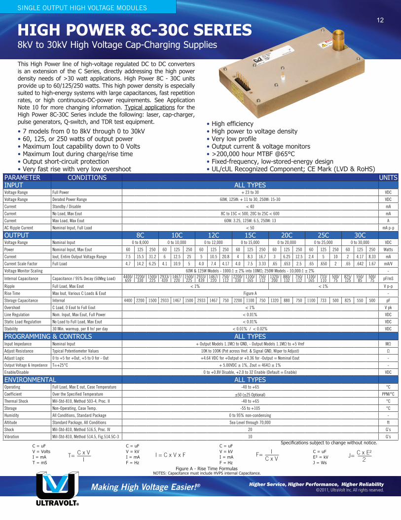
HIGH POWER 8C-30C SERIES This High Power line of high-voltage regulated DC to DC converters is an extension of the C Series, directly addressing the high power density needs of >30 watt applications. High Power 8C - 30C units provide up to 60/125/250 watts. This high power density is especially suited to high-energy systems with large capacitances, fast repetition rates, or high continuous-DC-power requirements. See Application Note 10 for more changing information. Typical applications for the High Power 8C-30C Series include the following: laser, cap-charger, pulse generators, Q-switch, and TDR test equipment. • 7 models from 0 to 8kV through 0 to 30kV • 60, 125, or 250 watts of output power • Maximum Iout capability down to 0 Volts • Maximum Iout during charge/rise time • Output short-circuit protection • Very fast rise with very low overshoot • High efficiency • High power to voltage density • Very low profile • Output current & voltage monitors • >200,000 hour MTBF @65°C • Fixed-frequency, low-stored-energy design • UL/cUL Recognized Component; CE Mark (LVD & RoHS) 8kV to 30kV High Voltage Cap-Charging Supplies SINGLE OUTPUT HIGH VOLTAGE MODULES PARAMETER CONDITIONS UNITS INPUT ALL TYPES Voltage Range Full Power + 23 to 30 VDC Voltage Range Derated Power Range 60W, 125W: + 11 to 30, 250W: 15-30 VDC Current Standby / Disable < 40 mA Current No Load, Max Eout 8C to 15C < 500, 20C to 25C < 600 mA Current Max Load, Max Eout 60W: 3.25, 125W: 6.5, 250W: 13 A AC Ripple Current Nominal Input, Full Load < 50 mA p-p OUTPUT 8C 10C 12C 15C 20C 25C 30C Voltage Range Nominal Input 0 to 8,000 0 to 10,000 0 to 12,000 0 to 15,000 0 to 20,000 0 to 25,000 0 to 30,000 VDC Power Nominal Input, Max Eout 60 125 250 60 125 250 60 125 250 60 125 250 60 125 250 60 125 250 60 125 250 Watts Current Iout, Entire Output Voltage Range 7.5 15.5 31.2 6 12.5 25 5 10.5 20.8 4 8.3 16.7 3 6.25 12.5 2.4 5 10 2 4.17 8.33 mA Current Scale Factor Full Load 4.7 14.2 6.25 4.1 10.9 5 4.0 7.4 4.17 4.0 7.5 3.33 .65 .653 2.5 .65 .650 2 .65 .642 1.67 mA/V Voltage Monitor Scaling 60W & 125W Models - 1000:1 ± 2% into 10MΩ; 250W Models - 10,000:1 ± 2% - Internal Capacitance Capacitance / 95% Decay (50Meg Load) 4400/ 659 2200/ 330 1500/ 225 2933/ 439 1467/ 220 1500/ 225 2933/ 439 1467/ 220 750/ 112 2200/ 330 1100/ 165 750/ 112 1320/ 200 880/ 132 750/ 112 1100/ 165 733/ 110 500/ 75 825/ 125 550/ 85 500/ 75 pF/mS Ripple Full Load, Max Eout < 1% < 1% V p-p Rise Time Max Iout, Various C Loads & Eout Figure A - Storage Capacitance Internal 4400 2200 1500 2933 1467 1500 2933 1467 750 2200 1100 750 1320 880 750 1100 733 500 825 550 500 pF Overshoot C Load, 0 Eout to Full Eout < 1% V pk Line Regulation Nom. Input, Max Eout, Full Power < 0.01% VDC Static Load Regulation No Load to Full Load, Max Eout < 0.01% VDC Stability 30 Min. warmup, per 8 hr/ per day < 0.01% / < 0.02% VDC PROGRAMMING & CONTROLS ALL TYPES Input Impedance Nominal Input + Output Models 1.1MΩ to GND, - Output Models 1.1MΩ to +5 Vref MΩ Adjust Resistance Typical Potentiometer Values 10K to 100K (Pot across Vref. & Signal GND, Wiper to Adjust) Ω Adjust Logic 0 to +5 for +Out, +5 to 0 for - Out +4.64 VDC for +Output or +0.36 for -Output = Nominal Eout - Output Voltage & Impedance T=+25°C + 5.00VDC ± 1%, Zout = 464Ω ± 1% - Enable/Disable 0 to +0.8V Disable, +2.0 to 32 Enable (Default = Enable) VDC ENVIRONMENTAL ALL TYPES Operating Full Load, Max E out, Case Temperature -40 to +65 °C Coefficient Over the Specified Temperature ±50 (±25 Optional) PPM/°C Thermal Shock Mil-Std-810, Method 503-4, Proc. II -40 to +65 °C Storage Non-Operating, Case Temp. -55 to +105 °C Humidity All Conditions, Standard Package 0 to 95% non-condensing - Altitude Standard Package, All Conditions Sea Level through 70,000 ft Shock Mil-Std-810, Method 516.5, Proc. IV 20 G’s Vibration Mil-Std-810, Method 514.5, Fig.514.5C-3 10 G’s Making High Voltage Easier! ® ULTRAVOLT® Higher Service, Higher Performance, Higher Reliability ©2011, UltraVolt Inc. All rights reserved. Specifications subject to change without notice. Figure A - Rise Time Formulas C = uF V = Volts I = mA T = mS C = uF V = kV I = mA F = Hz C = uF V = kV I = mA F = Hz C = uF E² = kV J = Ws NOTES: Capacitance must include HVPS internal Capacitance. T= C x V I I = C x V x F J= C x E² 2 F= I C x V 12