STARTING WITH PERMANENT CAPACITOR (PC)
Single phase induction motorsSelection tables
Version "P" Version "PR"
Main phase (PP)+ Auxiliary phase (Pa)+ PC
In
Nn
Pa PC
PP
N
min-1
Mn
N.m AIM
Id = 4 ln
Md = 0.6 Mn
Mn
Md = 2.5 Mn Main phase (PP)+ Auxiliary phase (Pa)+ PC
Main phase (PP)+ Auxiliary phase (Pa)+ PC + SC
In
Nn
Pa PC
SC
SC cut-off
PP
N
min-1
N.m AIM
Id = 6 ln
SINGLE PHASE INDUCTION MOTORSWITH SHORT-CIRCUIT ROTOR
STARTING WITH PERMANENT CAPACITOR (PC)AND STARTING CAPACITOR (SC)
1
Rated Rated Rated Power E�ciency Starting current / Starting torque / Max. torque / PC SC Weightspeed torque current factor* * Rated current** Rated torque** Rated torque 400 V 250 V
Type P N NN C N IN Cos � η ID / I N MD / MN MM / MN MF MF IM B3kW min -1 Nm %A kg
LS 56 P 0.09 2790 0.31 0.90 0.85 50 3.2 0.8 2.4 4 - 3.5
LS 56 P 0.12 2810 0.42 1.15 0.85 54 3.5 0.7 2.4 5 - 4
LS 63 P 0.12 2820 0.42 1.00 0.90 57 4 1 2.5 6 - 4
LS 63 P 0.18 2820 0.61 1.40 0.90 62 4.5 0.9 2.3 8 - 4.5
LS 63 P 0.25 2830 0.84 2.00 0.90 62 4.5 0.9 2.5 10 - 5
LS 71 P 0.25 2780 0.86 1.95 0.90 61 3.5 0.6 2 8 - 5.5
LS 71 P 0.37 2850 1.24 2.70 0.85 70 4.7 0.5 2.3 10 - 7
LS 71 P 0.55 2770 1.90 3.50 0.95 72 4.5 0.6 2.2 16 - 7.5
LS 80 P 0.55 2730 1.93 3.80 0.98 64 4 0.5 2 16 - 8.5
LS 80 P 0.75 2780 2.60 4.85 0.95 70 4.2 0.6 2.2 25 - 9
LS 80 P 1.10 2760 3.80 6.60 0.98 73 4.1 0.5 2 32 - 11
LS 90 P 1.10 2700 3.90 7.50 0.90 73 4.6 0.5 2.2 25 - 14
LS 90 P 1.50 2780 5.15 9.10 0.95 76 4.8 0.7 2.8 50 - 16.5
LS 63 PR 0.18 2900 0.60 1.40 0.85 66 6.3 3.2 2.8 6 30 5
LS 63 PR 0.25 2890 0.83 1.80 0.95 66 6 3 2.6 10 30 5.5
LS 71 PR 0.25 2900 0.83 2.00 0.85 65 5.5 2.4 3 8 30 6
LS 71 PR 0.37 2920 1.20 2.80 0.85 68 6.6 2.3 3.2 12 40 7.5
LS 71 PR 0.55 2900 1.80 3.70 0.85 74 6.6 2.5 2.9 16 60 8
LS 80 PR 0.55 2860 1.83 3.80 0.98 67 5.4 2 2.5 16 60 9
LS 80 PR 0.75 2880 2.50 4.90 0.90 74 6 2.7 2.8 20 100 9.5
LS 80 PR 1.10 2860 3.70 6.60 0.90 77 5.8 1.8 2.6 25 100 11
LS 90 PR 1.50 2860 5.00 8.60 0.98 76 6 2.2 2.4 32 160 14.5
LS 90 PR 1.80 2870 6.00 10.50 0.98 76 6.3 1.9 2.4 40 160 17
LS 100 LPR 2.20 2900 7.50 14.20 0.92 74 6.4 2 2.1 30/450V 200/290V -
LS 112 MPR 3.00 2870 10.00 16.80 0.98 77 6 1.6 1.8 40/450V 200/290V -
LS 112 MGPR 4.00 2940 13.20 22.00 0.98 80 6.1 1.4 2.1 60/450V 400/290V -
LS 132 MPR 5.50 2900 18.70 33.00 0.93 78 5.5 1.9 1.8 60/450V 600/290V -
Ratedpower
at 50 Hz
MAINS SUPPLY 230 V 50 Hz
2Poles3000 min -1
E1 - Selection data : SINGLE SPEEDIP 55 - S1Cl. FMULTIVOLTAGE
Single phase induction motorsSelection tables
2
Rated Rated Rated Power E�ciency Starting current / Starting torque / Max. torque / PC SC Weightspeed torque current factor* * Rated current** Rated torque** Rated torque 400 V 250 V
Type P N NN C N IN Cos � η ID / I N MD / MN MM / MN MF MF IM B3kW min -1 Nm %A kg
LS 56 P 0.06 1420 0.40 0.72 0.90 39 2.7 1.3 2.3 6 - 3.5
LS 63 P 0.09 1380 0.62 0.75 0.95 55 2.4 0.7 1.4 6 - 4
LS 63 P 0.12 1400 0.82 1.00 0.95 55 2.9 0.9 1.8 8 - 4.5
LS 63 P 0.18 1370 1.25 1.30 0.95 61 2.7 0.7 1.5 10 - 5
LS 71 P 0.18 1430 1.20 1.80 0.75 57 3.9 0.6 2.6 8 - 6
LS 71 P 0.25 1430 1.66 2.10 0.80 63 4.3 0.6 2.3 10 - 6.5
LS 71 P 0.37 1410 2.50 2.80 0.85 66 4 0.5 1.9 12 - 7.5
LS 80 P 0.37 1340 2.66 2.90 0.85 63 3.1 0.4 1.5 10 - 8
LS 80 P 0.55 1370 3.90 4.20 0.85 67 3.6 0.4 1.6 16 - 8.5
LS 80 P 0.75 1370 5.20 5.40 0.85 69 3.9 0.4 1.7 20 - 10.5
LS 90 P 0.75 1370 5.20 4.80 0.90 72 3.9 0.4 1.7 20 - 14.5
LS 90 P 1.10 1420 7.45 7.00 0.95 71 5 0.6 2.4 40 - 16
LS 63 PR 0.12 1430 0.82 1.05 0.90 57 4.2 2.2 1.9 5 16 5
LS 63 PR 0.18 1410 1.22 1.50 0.85 60 3.7 1.7 1.7 5 16 5.5
LS 71 PR 0.18 1460 1.20 1.70 0.75 59 5 2.7 2.8 8 30 6
LS 71 PR 0.25 1460 1.65 2.20 0.75 66 4.9 2.3 2.5 8 30 7
LS 71 PR 0.37 1440 2.45 2.80 0.85 68 4.7 2.1 2.2 12 40 8
LS 80 PR 0.37 1420 2.45 2.80 0.85 65 4.2 2 1.8 10 40 8.5
LS 80 PR 0.55 1420 3.70 4.20 0.90 65 4.5 1.9 1.9 16 60 9
LS 80 PR 0.75 1430 5.00 5.20 0.85 73 5 2.7 1.9 20 80 10.5
LS 90 PR 0.75 1440 5.00 4.70 0.90 73 5.3 2 2.3 20 80 13
LS 90 PR 1.10 1420 7.36 6.90 0.95 71 4.9 1.9 1.9 25 120 14
LS 90 PR 1.50 1430 10.00 8.60 0.98 76 5.5 1.8 2 40 160 17
LS 100 LPR 2.20 1445 15.00 14.00 0.93 74 5 1.4 1.7 50/450V 200/290V -
LS 112 MPR 3.00 1430 20.00 19.30 0.90 74 4 1.3 1.6 50/450V 200/290V -
LS 132 SMPR 4.00 1455 27.00 22.00 0.97 81 7 1.8 2.1 120/450V 600/290V -
LS 132 MPR 5.50 1455 37.00 33.20 0.90 80 7 1.8 1.8 120/450V 800/290V -
Ratedpower
at 50 Hz
MAINS SUPPLY 230 V 50 Hz
4Poles1500 min -1
IP 55 - S1Cl. FMULTIVOLTAGE
Single phase induction motorsSelection tables
IP 55 - S1Cl. FMULTIVOLTAGE
Rated Rated Rated Power E�ciency Starting current / Starting torque / Max. torque / PC SC Weightspeed torque current factor* * Rated current** Rated torque** Rated torque** 400 V 250 V
Type P N NN C N IN Cos � η ID / I N MD / MN MM / MN MF MF IM B3kW min -1 Nm %A kg
LS 71 P 0.12 900 1.26 1.00 0.95 52 2.5 0.8 1.4 8 - 7
LS 80 P 0.37 920 3.81 3.00 0.98 53 2.8 0.9 1.9 25 - 10
Ratedpower
at 50 Hz
MAINS SUPPLY 230 V 50 Hz
6Poles1000 min -1
3
F1 - Dimensions of shaft extensions
E
D
M.O x p
EA
DA
MOA x pA
F
GD G
FA
GF GB
2, 4 and 6 poles
F GD D E G O p
LS 56 3 3 9j6 20 7 4 10
LS 63 4 4 11j6 23 8.5 4 10
LS 71 5 5 14j6 30 11 5 15
LS 80 6 6 19j6 40 15.5 6 16
LS 90 8 7 24j6 50 20 8 19
LS 100 L PR 8 7 28j6 60 24 10 22
LS 112 M/MG PR 8 7 28j6 60 24 10 22
LS 132 S/M PR 10 8 38k6 80 33 12 28
Main shaft extensions
Type
2, 4 and 6 poles
FA GF DA GB EA OA pA
LS 56 3 3 9j6 7 20 4 10
LS 63 4 4 11j6 8.5 23 4 10
LS 71 5 5 14j6 11 30 5 15
LS 80 5 5 14j6 11 30 5 15
LS 90 6 6 19j6 15.5 40 6 16
LS 100 L PR 8 7 24j6 20 50 8 19
LS 112 M/MG PR 8 7 24j6 20 50 8 19
LS 132 S/M PR 8 7 28j6 24 60 10 22
Secondary shaft extensions
Type
Dimensions in millimetres
Single phase induction motorsDimensions
4
A AB B BB C AA S HD Z max. H LJ HA x LB AC J I F GD D E G O p
LS 56 P 90 104 71 87 36 24 6 148 90 56 8 7 8 156 110 86 88 3 3 9 j6 20 7.2 4 10
LS 63 P1 100 115 80 97 40 24.5 7 160 90 63 18 8 8.5 172 126 86 88 4 4 11 j6 23 8.5 4 10
LS 63 PR1 100 115 80 97 40 24.5 7 182 100 63 21.5 8 8.5 172 126 138 105 4 4 11 j6 23 8.5 4 10
LS 71 P2 112 126 90 106 45 23 7 178 90 71 18 9 8 185 140 86 88 5 5 14 j6 30 11 5 12.5
LS 71 PR2 112 126 90 106 45 23 7 200 100 71 21.5 9 8 185 140 138 105 5 5 14 j6 30 11 5 12.5
LS 80 P 125 157 100 120 50 37 9 201 100 80 24.5 10 10 215 162 86 88 6 6 19 j6 40 15.5 6 15
LS 80 PR 125 157 100 120 50 37 9 223 115 80 24.5 10 10 215 162 138 105 6 6 19 j6 40 15.5 6 15
LS 90 P 140 172 125 162 56 30 9 221 108 90 24.5 11 27.5 245 182 86 88 8 7 24 j6 50 20 8 20
LS 90 PR 140 172 125 162 56 30 9 243 115 90 24.5 11 27.5 245 182 138 105 8 7 24 j6 50 20 8 20
LS 100 LPR 160 196 140 165 63 40 12 259 100 100 26 13 12 290 200 138 104 8 7 28 j6 60 24 10 22
LS 112 MPR 190 220 140 165 70 45 12 271 100 112 26 14 12 290 200 138 104 8 7 28 j6 60 24 10 22
LS 112 MGPR 190 220 140 165 70 52 12 280 140 112 36 14 12 315 235 138 104 8 7 28 j6 60 24 10 22
LS 132 SM/MPR3 216 250 178 208 89 59 12 307 - 132 25 18 16 387 280 110 130 10 8 38 k6 80 33 12 28
MotorsType
F2 - Foot mounted IM B3 (IM 1001)
PE n°
A
HD
H HA
AB
AA4 Ø K
I
Z
J LJ
LB E
Ø AC
x
B C
BB
D
M.O x p
F
GD G
Dimensions in millimetres
Single phase induction motorsDimensions
Dimensions of LS single phase TEFV induction motors - IP 55Cage rotor
- foot mounted
The permanent capacitor is mounted on the outside of the terminal box.The starting capacitor is located inside the terminal box.
Shaft extension
- symbol on housing : not identified for frame sizes 56 to 90 mm.
1. LS 63 motors are also fitted with a shaft extension Ø14 x 30 (non-standard). Motors LS 63 P, 2 P, 0.25 kW and LS 63 P, 4 P, 0.18 kW : change to dimension LB = 187 Motors LS 63 PR, 2 P, 0.25 kW and LS 63 PR, 4 P, 0.18 kW : change to dimension LB = 1872. Motors LS 71 P, 2 P, 0.55 kW and LS 71 P, 4 P, 0.37 kW : change to dimension LB = 193.3. Motors supplied with separate electrical cabinet.
5
F3 - Foot and flange mounted IM B35 (IM 2001)
A
HD
H
I
HA
AB
AA
M
n Ø S
4 Ø K
α
Z
LA
J LJ
LB
T
x
B C
N PJ6
Ø AC
BB
E
D
M.O x p
F
GD G
Single phase induction motorsDimensions
Dimensions in millimetres- foot and flange mounted (FF)
The permanent capacitor is mounted on the outside of the terminal box.The starting capacitor is located inside the terminal box.
A AA AB C B BB H HA x HD K HJ Z max LJ LB AC J I
LS 56 P 90 24 104 36 71 87 56 7 8 148 6 92 90 8 156 110 86 88
LS 63 P1 100 24.5 115 40 80 97 63 8 8.5 160 7 97 90 18 172 126 86 88
LS 63 PR1 100 24.5 115 40 80 97 63 8 8.5 182 7 119 100 21.5 172 126 138 105
LS 71 P2 112 23 126 45 90 106 71 9 8 178 7 107 90 18 185 140 86 88
LS 71 PR2 112 23 126 45 90 106 71 9 8 200 7 129 100 21.5 185 140 138 105
LS 80 P 125 37 157 50 100 120 80 10 10 201 9 121 100 24.5 215 162 86 88
LS 80 PR 125 37 157 50 100 120 80 10 10 223 9 143 115 24.5 215 162 138 105
LS 90 P 140 30 172 56 125 162 90 11 27.5 221 9 131 108 24.5 265 182 86 88
LS 90 PR 140 30 172 56 125 162 90 11 27.5 243 9 153 115 24.5 265 182 138 105
LS 100 LPR 160 40 196 63 140 165 100 13 12 259 12 159 100 26 290 200 138 104
LS 112 MPR 190 45 220 70 140 165 112 14 12 271 12 159 100 26 290 200 138 104
LS 112 MGPR 190 52 220 70 140 165 112 14 12 280 12 168 140 36 315 235 138 104
LS 132 SM/MPR3 216 59 250 89 178 208 132 18 16 307 12 175 - 25 387 280 110 130
MotorsType
Dimensions of LS single phase TEFV induction motors - IP 55Cage rotor
1. LS 63 motors are also fitted with a shaft extension Ø14 x 30 (non-standard). Motors LS 63 P, 2 P, 0.25 kW and LS 63 P, 4 P, 0.18 kW : change to dimension LB = 187 Motors LS 63 PR, 2 P, 0.25 kW and LS 63 PR, 4 P, 0.18 kW : change to dimension LB = 1872. Motors LS 71 P, 2 P, 0.55 kW and LS 71 P, 4 P, 0.37 kW : change to dimension LB = 193.3. Motors supplied with separate electrical cabinet.
6
F4 - Flange mounted IM B5 (IM 3001)
HJ
M
α
PE n°
n Ø S
I
Z
LA
J LJ
LB
T
N PJ6
Ø AC
E
D
M.O x p
F
GD G
Single phase induction motorsDimensions
Dimensions in millimetres- flange mounted (FF)
The permanent capacitor is mounted on the outside of the terminal box.The starting capacitor is located inside the terminal box.
Symb. M N P LA α T S F GD D E G O p
LS 56 P FF 100 100 80 120 8 45 ° 3 7 3 3 9 j6 20 7.2 4 10
LS 63 P1 FF 115 115 95 140 10 45 ° 3 9 4 4 11 j6 23 8.5 4 10
LS 63 PR1 FF 115 115 95 140 10 45 ° 3 9 4 4 11 j6 23 8.5 4 10
LS 71 P2 FF 130 130 110 160 8 45 ° 3.5 9 5 5 14 j6 30 11 5 12.5
LS 71 PR2 FF 130 130 110 160 8 45 ° 3.5 9 5 5 14 j6 30 11 5 12.5
LS 80 P FF 165 165 130 200 10 45 ° 3.5 11 6 6 19 j6 40 15.5 6 15
LS 80 PR FF 165 165 130 200 10 45 ° 3.5 11 6 6 19 j6 40 15.5 6 15
LS 90 P FF 165 165 130 200 10 45 ° 3.5 11 8 7 24 j6 50 20 8 20
LS 90 PR FF 165 165 130 200 10 45 ° 3.5 11 8 7 24 j6 50 20 8 20
LS 100 LPR FF 215 215 180 250 12 45 ° 4 14.5 8 7 28 j6 60 24 10 22
LS 112 MPR FF 215 215 180 250 12 45 ° 4 14.5 8 7 28 j6 60 24 10 22
LS 112 MGPR FF 215 215 180 250 12 45 ° 4 14.5 8 7 28 j6 60 24 10 22
LS 132 SM/MPR3 FF 265 265 230 300 14 45 ° 4 14.5 10 8 38 k6 80 33 12 28
FlangesType
Shaft extension
Dimensions of LS single phase TEFV induction motors - IP 55Cage rotor
1. LS 63 motors are also fitted with a shaft extension Ø14 x 30 (non-standard). Motors LS 63 P, 2 P, 0.25 kW and LS 63 P, 4 P, 0.18 kW : change to dimension LB = 187 Motors LS 63 PR, 2 P, 0.25 kW and LS 63 PR, 4 P, 0.18 kW : change to dimension LB = 1872. Motors LS 71 P, 2 P, 0.55 kW and LS 71 P, 4 P, 0.37 kW : change to dimension LB = 193.3. Motors supplied with separate electrical cabinet.
7
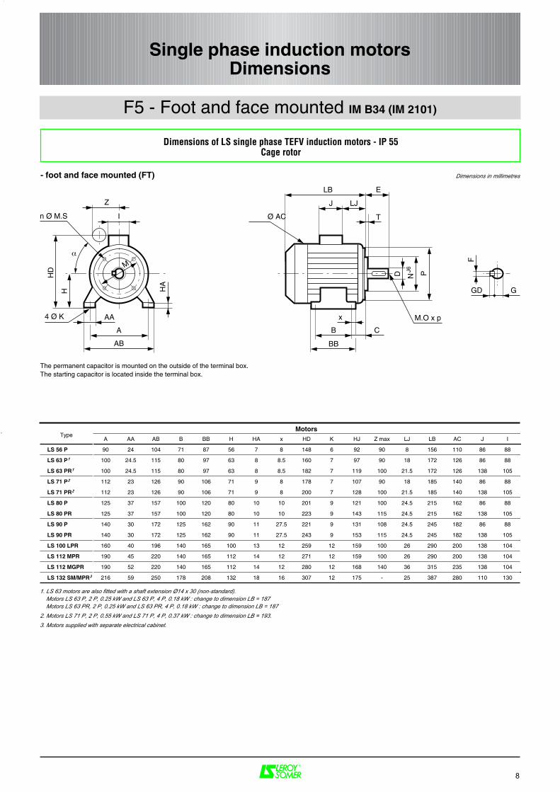
F5 - Foot and face mounted IM B34 (IM 2101)
A
HD
H HA
AB
AA4 Ø K
M
n Ø M.S
α
I
Z J LJ
LB
T
N PJ6
Ø AC
x
B C
BB
E
D
M.O x p
F
GD G
Single phase induction motorsDimensions
Dimensions in millimetres- foot and face mounted (FT)
The permanent capacitor is mounted on the outside of the terminal box.The starting capacitor is located inside the terminal box.
A AA AB B BB H HA x HD K HJ Z max LJ LB AC J I
LS 56 P 90 24 104 71 87 56 7 8 148 6 92 90 8 156 110 86 88
LS 63 P1 100 24.5 115 80 97 63 8 8.5 160 7 97 90 18 172 126 86 88
LS 63 PR1 100 24.5 115 80 97 63 8 8.5 182 7 119 100 21.5 172 126 138 105
LS 71 P2 112 23 126 90 106 71 9 8 178 7 107 90 18 185 140 86 88
LS 71 PR2 112 23 126 90 106 71 9 8 200 7 128 100 21.5 185 140 138 105
LS 80 P 125 37 157 100 120 80 10 10 201 9 121 100 24.5 215 162 86 88
LS 80 PR 125 37 157 100 120 80 10 10 223 9 143 115 24.5 215 162 138 105
LS 90 P 140 30 172 125 162 90 11 27.5 221 9 131 108 24.5 245 182 86 88
LS 90 PR 140 30 172 125 162 90 11 27.5 243 9 153 115 24.5 245 182 138 105
LS 100 LPR 160 40 196 140 165 100 13 12 259 12 159 100 26 290 200 138 104
LS 112 MPR 190 45 220 140 165 112 14 12 271 12 159 100 26 290 200 138 104
LS 112 MGPR 190 52 220 140 165 112 14 12 280 12 168 140 36 315 235 138 104
LS 132 SM/MPR3 216 59 250 178 208 132 18 16 307 12 175 - 25 387 280 110 130
MotorsType
Dimensions of LS single phase TEFV induction motors - IP 55Cage rotor
1. LS 63 motors are also fitted with a shaft extension Ø14 x 30 (non-standard). Motors LS 63 P, 2 P, 0.25 kW and LS 63 P, 4 P, 0.18 kW : change to dimension LB = 187 Motors LS 63 PR, 2 P, 0.25 kW and LS 63 PR, 4 P, 0.18 kW : change to dimension LB = 1872. Motors LS 71 P, 2 P, 0.55 kW and LS 71 P, 4 P, 0.37 kW : change to dimension LB = 193.3. Motors supplied with separate electrical cabinet.
8
F6 - Face mounted IM B14 (IM 3601)
HJ
AC
M
Ø M.S
α
PE n°I
Z J LJ
LB
T
N PJ6
E
D
M.O x p
F
GD G
Single phase induction motorsDimensions
Dimensions in millimetres- face mounted (FT)
The permanent capacitor is mounted on the outside of the terminal box.The starting capacitor is located inside the terminal box.
Symb. M N P α T M-S F GD D E G O p
LS 56 P FT 65 65 50 80 45 ° 2.5 5 3 3 9 j6 20 7.2 4 10
LS 63 P1 FT 75 75 60 90 45 ° 2.5 5 4 4 11 j6 23 8.5 4 10
LS 63 PR1 FT 75 75 60 90 45 ° 2.5 5 4 4 11 j6 23 8.5 4 10
LS 71 P2 FT 85 85 70 105 45 ° 2.5 6 5 5 14 j6 30 11 5 12.5
LS 71 PR2 FT 85 85 70 105 45 ° 2.5 6 5 5 14 j6 30 11 5 12.5
LS 80 P FT 100 100 80 120 45 ° 3 6 6 6 19 j6 40 15.5 6 15
LS 80 PR FT 100 100 80 120 45 ° 3 6 6 6 19 j6 40 15.5 6 15
LS 90 P FT 115 115 95 140 45 ° 3 8 8 7 24 j6 50 20 8 20
LS 90 PR FT 115 115 95 140 45 ° 3 8 8 7 24 j6 50 20 8 20
LS 100 LPR FT 130 130 110 160 45 ° 3.5 8 8 7 28 j6 6 24 10 22
LS 112 MPR FT 130 130 110 160 45 ° 3.5 8 8 7 28 j6 6 24 10 22
LS 112 MGPR FT 130 130 110 160 45 ° 3.5 8 8 7 28 j6 60 24 10 22
LS 132 SM/MPR3 FT 215 215 180 250 45 ° 4 10 10 8 38 k6 80 33 12 28
FlangesType
Shaft extension
Dimensions of LS single phase TEFV induction motors - IP 55Cage rotor
F7 - Electrical cabinet for LS 132G
H1
H2
P
L
L P H1 H2 G Max. weight in kg
250 150 400 325 175 12
Dimensions in millimetres
1. LS 63 motors are also fitted with a shaft extension Ø14 x 30 (non-standard). Motors LS 63 P, 2 P, 0.25 kW and LS 63 P, 4 P, 0.18 kW : change to dimension LB = 187 Motors LS 63 PR, 2 P, 0.25 kW and LS 63 PR, 4 P, 0.18 kW : change to dimension LB = 1872. Motors LS 71 P, 2 P, 0.55 kW and LS 71 P, 4 P, 0.37 kW : change to dimension LB = 193.3. Motors supplied with separate electrical cabinet.
9
Optionally, LEROY-SOMER motors can be�tted with �anges and faceplates that arelarger or smaller than standard. This meansthat motors can be adapted to all types ofsituation without the need for costly andtime-consuming modi�cations.
G1 - Non-standard �anges
LA T
N PJ6
M
n Ø S
LA T
N PJ6
M
n Ø S
M N P T n S LA
FF 100 100 80 120 3 4 7 5
FF 115 115 95 140 3 4 10 10
FF 130 130 110 160 3.5 4 10 10
FF 165 165 130 200 3.5 4 12 10
FF 215 215 180 250 4 4 14.5 12
FF 265 265 230 300 4 4 14.5 14
FF 300 300 250 350 5 4 18.5 14
The tables below give �ange and faceplatedimensions and �ange/motor compatibility.The bearing and shaft extension for eachframe size remain standard.
IECsymbol
M
n x MST
N PJ6
T
N PJ6
M
n x MS
M N P T n M.S
FT 65 65 50 80 2.5 4 M5
FT 75 75 60 90 2.5 4 M5
FT 85 85 70 105 2.5 4 M6
FT 100 100 80 120 3 4 M6
FT 115 115 95 140 3 4 M8
FT 130 130 110 160 3.5 4 M8
FT 165 165 130 200 3.5 4 M10
FT 215 215 180 250 4 4 M12
FT 265 265 230 300 4 4 M12
Flange dimensionsIECsymbol
Flange mounted (FF)
Face mounted (FT)
MAIN FLANGE DIMENSIONS
Flange dimensions
Dimensions in millimetres
Single phase induction motorsOptional features
10