Design Guide for Single Ply Roofing Single Ply Roofing Association To ensure that clients obtain high quality polymer-based single ply roofing, through a partnership of quality assured manufacturers & contractors.
Transcript
Design Guidefor Single Ply Roofing
Single Ply Roofing Association
To ensure that clients obtain high quality polymer-based singleply roofing, through a partnership of qualityassured manufacturers & contractors.
1. OBJECTIVES AND
SCOPE
2. PERFORMANCE
TARGETS AND
CONSTRAINTS2.1 Introduction p 4
2.2 Durability p 4
2.3 Appearance p 5
2.4 Thermal performance p 5
2.5 Resistance to solar
radiation p 5
2.6 Control of condensation p 5
2.7 Control of air leakage p 5
2.8 Acoustic performance p 5
2.9 Resistance to loading p 5
2.10 External fire
performance p 5
2.11 Transmission of daylight p 6
2.12 Lightning protection p 6
2.13 Environmental impact p 6
2.14 Security p 6
2.15 Supplementary uses p 6
2.16 Maintenance frequency
and cost p 6
2.17 Safety during
construction and use p 6
3. DESIGN
CONSIDERATIONS3.1 Introduction p 7
3.2 Types of roof system p 7
3.2.1 The warm roof p 7
3.2.2 The inverted warm roof p 7
3.2.3 The cold roof p 8
3.2.4 Roof gardens or ‘green’
roofs p 8
3.3 Falls p 8-9
3.4 Drainage p 9
3.5 Thermal insulation p 9
3.5.1 Selection criteria p 9
3.6 Solar radiation p 9
3.7 Control of condensation p 9-10
3.8 Control of air leakage p 10
3.9 Acoustic insulation p 10
3.10 Compatibility p 10
3.11 Loads p 10
3.11.1 Wind p 10
3.11.2 Foot traffic p 11
3.11.3 Plant and equipment p 11
3.12 External fire
performance p 11
3.13 Lightning protection p 11
3.14 Methods of attachment p 12
3.14.1 Introduction p 12
3.14.2 Mechanical fastening p 12-13
3.14.3 Adhesion p 13
3.14.4 Ballast p 13
3.15 Detailing p 14-15
3.16 Safety during
construction and use p 15
4. MATERIALS4.1 Deck p 15
4.1.1 Introduction p 15
4.1.2 Profiled metal sheet p 15-16
4.1.3 Timber p 16
4.1.4 Concrete p 16
4.2 Vapour control layer p 16
4.3 Thermal insulation p 16
4.3.1 Classification p 16
4.3.2 Cellular materials p 17
4.3.3 Fibrous materials p 17
4.4 Waterproof membrane p 17
4.4.1 Introduction p 17
4.4.2 Product certification p 17
4.4.3 Product standards p 17-18
4.4.4 Generic types of
membrane p 18
4.5 Ancillary components p 18
4.5.1 Introduction p 18
4.5.2 Mechanical fasteners p 18
4.5.3 Adhesives p 19
4.5.4 Pre-formed details p 19
4.5.5 Rainwater outlets p 19
4.5.6 Fall-arrest anchorages p 19
4.5.7 Lightning conductor pads p 19
5. WORKMANSHIP5.1 Training certification p 19
5.2 Programme p 19
5.3 Storage and handling of
materials p 19
5.4 Health and Safety;
COSHH Regulations p 20
5.5 Existing substrate
(refurbishment only) p 20
5.6 Deck p 20
5.7 Vapour control layer p 20
5.8 Thermal insulation p 20
5.8.1 Mechanical fastening p 20
5.8.2 Adhesion p 21
5.9 Waterproof membrane p 21
5.9.1 Mechanical fastening p 21
5.9.2 Adhesion p 21
5.9.3 Ballast p 22
5.10 Temporary protection
of roof system p 22
5.11 Inspection p 22
5.12 Integrity testing p 22-23
6. MAINTENANCE
7. REFURBISHMENT7.1 Introduction p 23
7.2 Removal or overlay of
existing system p 23
7.3 Change of use p 23
7.4 Existing deck p 23
7.5 Insulation p 23
8. REFERENCES8.1 Regulations p 24
8.2 Normative references p 24
8.3 Informative references p 24
8.4 Other references p 24
Design Guide for Single Ply Roofing
CONTENTS
3
1. OBJECTIVES AND
SCOPEThis Guide is intended to:
• Assist the decision-making process
in the design of a roof system
based upon polymeric single ply
water-proofing membranes.
• Provide the designer with technical
information which, together
with manufacturers’ advice and
published Regulations and
Standards will be sufficient for
the design of a single ply roof.
Section 5 ‘Workmanship’ is intended
to inform the designer of those
aspects which will be of relevance to
the design and supervision functions;
it is not an installation manual for
the contractor.
The recommendations given in
this Guide are applicable to all
roof forms in both new construction
and refurbishment. They do not
cover all aspects of single ply roofing
but feature those design aspects
believed to be important for
optimum performance.
In all instances it has been assumed
in drafting this Guide that
construction will be carried out
by operatives who have passed
the relevant SPRA manufacturers’
certified training course, under
the direction of qualified supervisors
as required by the SPRA criteria
for membership.
This document takes the form of
guidance and recommendations.
It should not be quoted as if it were
a specification and particular care
should be taken to ensure that claims
of compliance are not misleading.
Compliance with this Guide does
not in itself confer immunity from
legal obligations.
2. PERFORMANCE
TARGETS AND
CONSTRAINTS2.1 IntroductionFundamentally, a single ply roof
system must provide protection from
all weather conditions likely to be
experienced during its design life.
Such protection may be required
before building completion to
facilitate rapid fit-out of the interior.
In addition, the roof system must
perform satisfactorily against a wide
range of constraints and targets
required by legislation, by the client
and by the design of the substructure
and services.
At the earliest possible stage and
with the early involvement of the
membrane manufacturer, these
targets and constraints should be
identified by the client and designer,
together with the priority of each.
This will enable effective review and
modification as the design develops.
Since performance priorities are
unique to each design, the following
performance criteria are not ranked
in order of importance.
2.2 DurabilityDurability is expressed in terms of
anticipated life to renewal. In
financial terms, it is the period over
which the depreciated initial capital
cost and annual maintenance cost
does not exceed the annual cost
of a replacement roof.
The British Board of Agrément (BBA)
assesses the durability of single ply
roofing membranes as part of the
Agrément Certification process.
Single ply membranes are typically
given a life expectancy of between
"at least 20 years" and "in excess
of 25 years".
This Design Guide has been
prepared by the Technical
Committee of the Single Ply
Roofing Association (SPRA)
which comprises
representation from all
membership categories.
As such it represents the
current industry view of
best practice in the design,
installation and maintenance
of single ply roofing systems
and includes reference to
all relevant European and
British Standards as
appropriate. Since European
and British Standards and
Regulations are under
continuous review, the
reader should confirm their
status with the appropriate
institutions before referring
to them in specifications.
In the absence of a British
Standard for single ply
roofing, a British Board
of Agrément or WIMLAS
Certificate is required
to satisfy The Building
Regulations in respect
of fitness for purpose.
In addition, certain projects
may be subject to material
approvals to Factory Mutual
Research (FM - an affiliate of
FM Global) standards, which
set loss prevention standards
specified world-wide.
Design
Guide
for
Single
Ply
Roofing
4
2.3 Aesthetic appearanceThe overall appearance of the finished
roof with its necessary details, plus
any decorative surface finish. The
durability of the appearance should
also be considered.
2.4 Thermal performanceWherever possible, targets should
exceed those required by current
legislation in anticipation of higher
standards being set during the life
of the building. Initial investment
in high standards will be readily
offset by reduced heating and cooling
loads and by the building’s capacity
for adaptation to future change or
intensity of use. Such targets should
consider heat loss, heat gain, and
the impact of change (for example,
increased use of IT equipment
internally). The roofs of all heated
buildings are required by building
legislation to be thermally insulated.
The Approved Document Part L (2001
Edition) of the Building Regulations
(England & Wales), and Part J
(Scotland) implemented in 2002,
define the maximum permitted
Elemental U-value of flat roofs as:
Dwellings, commercial, industrial
& retail
• 0.25 W/m2.K
Alternative methods of compliance
with the Building Regulations include:
Dwellings
• Target U-value approach.• Carbon index method (dwellings).
Commercial, industrial & retail
• Whole building method.• Carbon emissions calculation
method.
Further guidance on these methods
is provided within the Approved
Document Parts L1 (Dwellings)
and L2, (England & Wales), and
Part J (Scotland).
2.5 Resistance to solar
radiationResistance to solar radiation concerns
issues of durability and of heat
absorption and radiation. Infrared
solar radiation has the potential to
increase significantly Summer cooling
loads, even on well-insulated roofs.
Its ultra-violet component is also a
major determinant in the ageing of
construction materials.
Heat absorption is a function of
colour and texture. Dark membranes
not only absorb more solar radiation
and transmit it to the rest of the roof
system; they also radiate heat at night
at a greater rate thereby cooling the
roof surface.
2.6 Control of
condensationSatisfactory performance in respect
of the control of condensation both
on the surface of and within the roof
system is essential if thermal and
durability targets are to be realised.
All designs should be checked in
terms of condensation risk for the
intended building function (and any
future change of use).
The Building Regulations Approved
Document sets mandatory
requirements in respect of the
control of condensation.
2.7 Control of air leakage Approved Document L of the Building
Regulations has introduced the
requirement that the roof and
those elements which penetrate
it, should be suitably airtight. It is
anticipated that with effect from
October 2003, the roof of a building
with a gross floor area in excess of
1000m2 will comply with the
requirement if the permeability to
air of the roof is tested to the
procedures defined in CIBSE TM23.
It should achieve permeability to
air not exceeding 10m2/h/m2 at a
reference pressure of 50Pa.
Buildings of less than 1000m2
gross floor area require a certificate
of conformity indicating that
appropriate design details and
building techniques have been used.
2.8 Acoustic performanceAll likely sources of external and
internal noise should be identified
in order to establish the degree of
attenuation required to suit the
building function. Because acoustic
performance is heavily dependent
upon the selection of materials
(especially the deck and thermal
insulation) early identification of the
requirement may assist the design
selection process.
On lightweight, wide-span structures,
noise from heavy rain is often
overlooked in design. However,
the inherent flexibility of single
ply membranes provides for good
attenuation when compared with
rigid sheet systems.
Advice with regards to individual
constructions is available from SPRA
insulation manufacturer members
(see 3.9).
2.9 Resistance to loading2.9.1 Resistance to wind loadWind load is established by
calculation in which site topography
and location are major determinants
but its level is also influenced by the
building design as a whole. It is
therefore advisable to estimate wind
load at an early stage. Detailed
calculation can then follow when
the design is more developed
(see 3.11.1).
2.9.2 Roof trafficConsideration should be given to the
suitability for roof traffic both during
and after construction. Areas that
will sustain heavy foot traffic after
installation but prior to completion
should be adequately protected.
Suitable provision should be made
for maintenance access to plant
and any other areas requiring
regular access. SPRA manufacturers
offer guidance in the treatment
of such areas including, in some
cases, materials for walkways and
load spreading.
2.10 External fire
performanceThe Building Regulations Approved
Document B: 2000 requires that roofs
of certain buildings meet specified
performance levels for exposure to
fire from external sources. This is
expressed as a requirement for the
whole roof construction, including
deck and covering, characterised by
penetration of fire and spread of
flame. Classification ranges from Ext.
FAA (External, Flat, Penetration rating
A, spread of flame rating A) to Ext.
FCD (lowest) when tested in
accordance with BS 476 Part 3: 1958.
Approved document B is under
review pending the confirmation of
a new classification system based on
a new European test for resistance to
fire. BS476 Part 3 will be withdrawn
following a transition period. Further
information should be obtained from
British Standards Institution and the
Department of Trade and Industry.
Performance in excess of the
mandatory requirement may be
specified by insurance loss
prevention consortia such as Loss
Prevention Council (LPC) or Factory
Mutual (FM). Currently, certification
to LPC is by testing to the British
Standard; to FM it is by testing
to an American standard.
5
2.11 Transmission of
daylightRooflights can provide very durable
and effective glare-free natural
lighting in deep plan buildings.
Since their size and position has
a significant effect upon drainage
and thermal design it is important
to establish the performance
requirement at an early stage.
2.12 Lightning protectionLightning protection is a function of
building location, design, materials
and internal use. Since lightning
protection works are usually part of
the electrical contract package,
effective integration of the roofing
and electrical design is important at
an early stage.
2.13 Environmental impactEnvironmental impact ranges from
consumption of natural resources
and energy during manufacture
and installation to removal, recycling
and disposal. Realistic durability and
maintenance input estimates are
an essential pre-requisite of
impact studies.
Thermal insulation performance
also has a major positive effect on
the environmental impact of any
roofing proposal.
The environmental impact of a
particular design is specific to that
design. Many simplistic impact
ratings for individual materials are
available, but in reality, the impact
of a design is dependent upon the
complete system and the client’s
selection of which environmental
issues are most important.
Therefore, it is recommended that the
client’s priorities for environmental
assessment be established at an
early stage.
SPRA members can provide a
variety of information regarding
the environmental profiles of the
materials they supply, including
the provision of recycled products.
The Association will base these
profiles upon agreed national
and international protocols,
as they develop.
2.14 SecurityRequired performance in respect of
security against access to and through
the roof should be established at an
early stage as this can influence the
selection of roof type and detailing.
2.15 Supplementary usesMechanical and electrical services are often subject to location and capacity
change during a building project and during service. Single ply roof systems are
unique in their adaptability to such change. However, the extent of design
flexibility likely to be required should be established, to avoid complex detailing
or difficult sequencing during construction.
2.16 Maintenance frequency and costSingle ply roofing systems require no maintenance in themselves but it is
established good practice to check roofs at least once per year and preferably
in early Spring and late Autumn (see 6.0 Maintenance).
2.17 Safety during construction and use In addition to safe methods of working with materials there is a requirement
to protect workers from falls.
The Construction Safety and Welfare Regulations 1966, statutory no.1592
Regulation 6, states that it is the responsibility of the employer to ensure that
any employee required to work at a height of 2 metres or more must be suitably
protected from any potential fall hazards.
The Construction Design and Management Regulations 1994 (CDM) extend the
responsibility for Health & Safety to the designer. The designer must ensure that
the design is such that it minimises risk during construction, maintenance and
repair. Failure to comply with these requirements could ultimately lead to
criminal as well as civil prosecution.
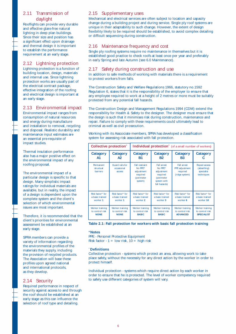
Working with its Asscociate members, SPRA has developed a classification
system for assessing risk associated with fall protection.
Table 2.1: Fall protection for workers with basic fall protection training
*NotesPPE - Personel Protective Equipment
Risk factor - 1 = low risk, 10 = high risk
+DefinitionsCollective protection - systems which protect an area, allowing work to take
place safely, without the necessity for any direct action by the worker in order to
protect himself.
Individual protection - systems which require direct action by each worker in
order to ensure that he is protected. The level of worker competency required
to safely use different categories of system will vary.
Permanent
structual
barriers
Risk factor* for
a basic trained
worker 1
Catagory A1
Collective protection+ Individual protection+(of a small number of workers)
Worker training
to control risk
NONE
Guard rails for
occasional
access
Risk factor* for
a basic trained
worker 1
Catagory A2
Worker training
to control risk
NONE
Fall restraint
No PPE*
adjustment
required
(perimeter
system)
Risk factor* for
a basic trained
worker 2
Catagory B1
Worker training
to control risk
BASIC
Fall arrest
No PPE*
adjustment
required
(perimeter
system with
fall hazards)
Risk factor* for
a basic trained
worker 3
Catagory B2
Worker training
to control risk
BASIC
Fall arrest
PPE adjustment
required
(ridge system)
Risk factor* for
a basic trained
worker 6
Catagory B3
Worker training
to control risk
ADVANCED
Roped access
(abseilling)
specialist
techniques
Risk factor* for
a basic trained
worker 10
Catagory C
Worker training
to control risk
SPECIALIST
6
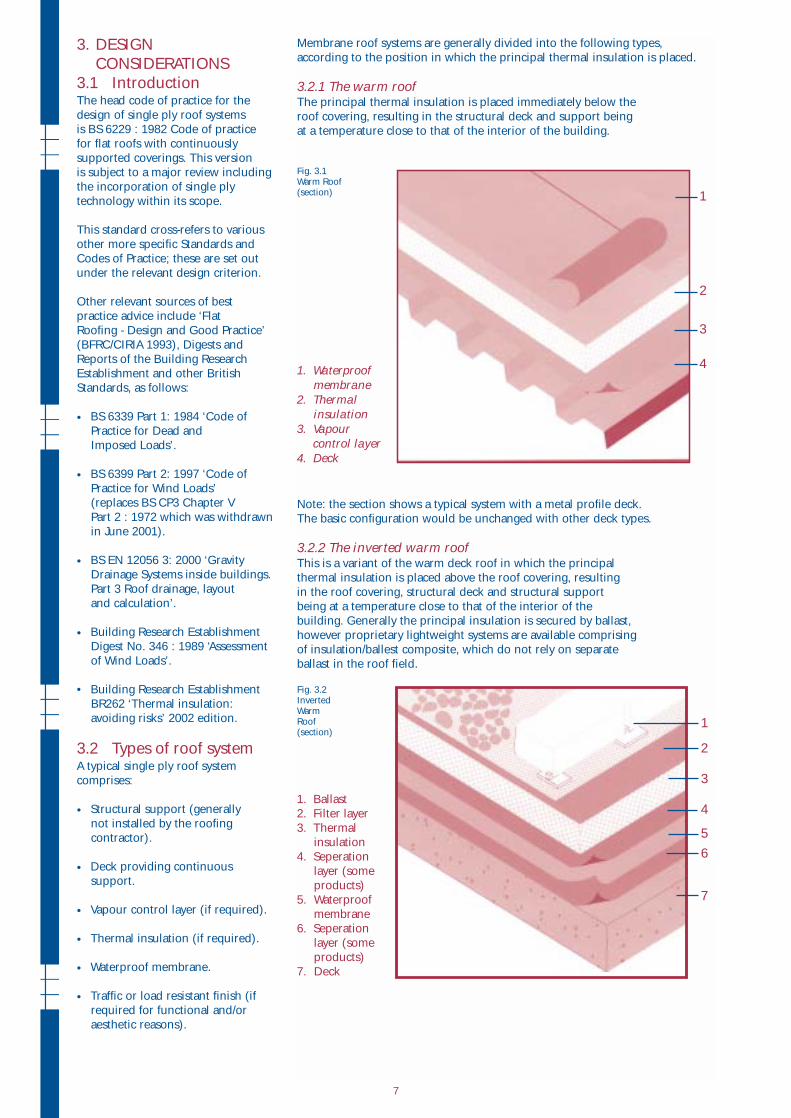
Membrane roof systems are generally divided into the following types,
according to the position in which the principal thermal insulation is placed.
3.2.1 The warm roof The principal thermal insulation is placed immediately below the
roof covering, resulting in the structural deck and support being
at a temperature close to that of the interior of the building.
Fig. 3.1 Warm Roof (section)
Note: the section shows a typical system with a metal profile deck.
The basic configuration would be unchanged with other deck types.
3.2.2 The inverted warm roofThis is a variant of the warm deck roof in which the principal
thermal insulation is placed above the roof covering, resulting
in the roof covering, structural deck and structural support
being at a temperature close to that of the interior of the
building. Generally the principal insulation is secured by ballast,
however proprietary lightweight systems are available comprising
of insulation/ballest composite, which do not rely on separate
ballast in the roof field.
Fig. 3.2 Inverted Warm Roof (section)
1
2
3
4
1
2
3
4
5
6
7
3. DESIGN
CONSIDERATIONS
3.1 IntroductionThe head code of practice for the
design of single ply roof systems
is BS 6229 : 1982 Code of practice
for flat roofs with continuously
supported coverings. This version
is subject to a major review including
the incorporation of single ply
technology within its scope.
This standard cross-refers to various
other more specific Standards and
Codes of Practice; these are set out
under the relevant design criterion.
Other relevant sources of best
practice advice include ‘Flat
Roofing - Design and Good Practice’
(BFRC/CIRIA 1993), Digests and
Reports of the Building Research
Establishment and other British
Standards, as follows:
• BS 6339 Part 1: 1984 ‘Code of
Practice for Dead and
Imposed Loads’.
• BS 6399 Part 2: 1997 ‘Code of
Practice for Wind Loads’
(replaces BS CP3 Chapter V
Part 2 : 1972 which was withdrawn
in June 2001).
• BS EN 12056 3: 2000 ‘Gravity
Drainage Systems inside buildings.
Part 3 Roof drainage, layout
and calculation’.
• Building Research Establishment
Digest No. 346 : 1989 ‘Assessment
of Wind Loads’.
• Building Research Establishment
BR262 ‘Thermal insulation:
avoiding risks’ 2002 edition.
3.2 Types of roof systemA typical single ply roof system
comprises:
• Structural support (generally
not installed by the roofing
contractor).
• Deck providing continuous
support.
• Vapour control layer (if required).
• Thermal insulation (if required).
• Waterproof membrane.
• Traffic or load resistant finish (if
required for functional and/or
aesthetic reasons).
1. Waterproof membrane
2. Thermal insulation
3. Vapourcontrol layer
4. Deck
1. Ballast
2. Filter layer
3. Thermal
insulation
4. Seperation
layer (some
products)
5. Waterproof
membrane
6. Seperation
layer (some
products)
7. Deck
7
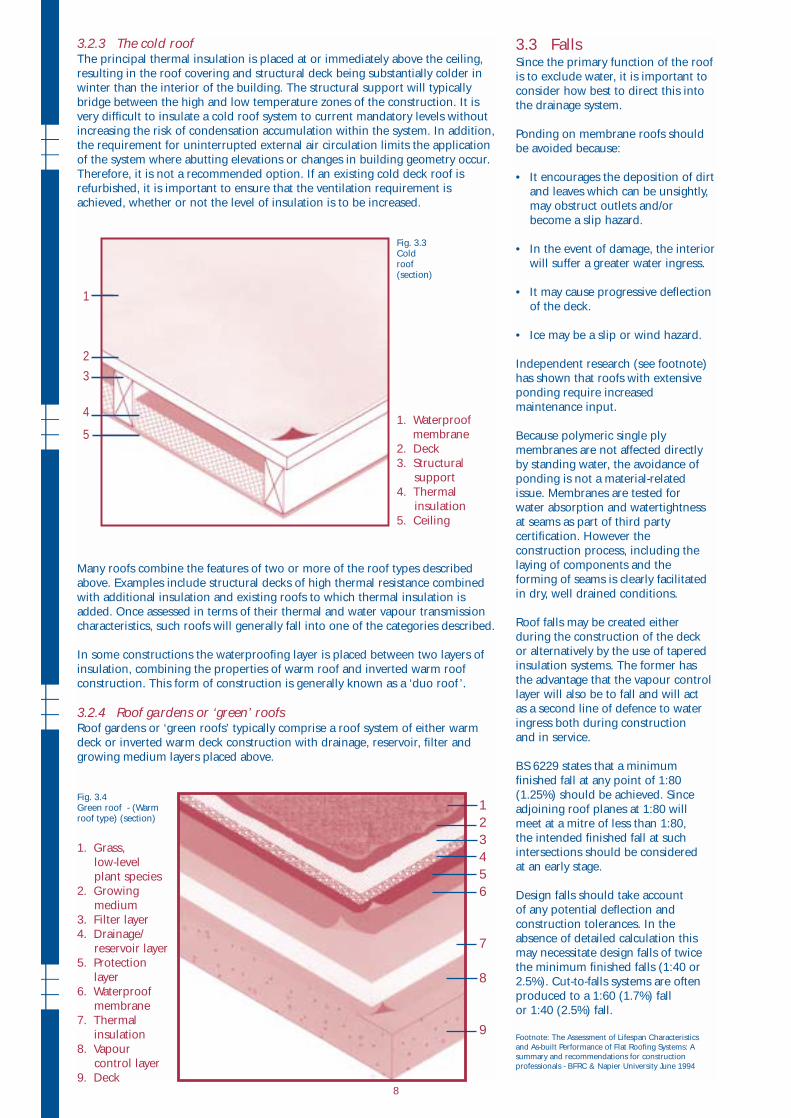
3.2.3 The cold roof The principal thermal insulation is placed at or immediately above the ceiling,
resulting in the roof covering and structural deck being substantially colder in
winter than the interior of the building. The structural support will typically
bridge between the high and low temperature zones of the construction. It is
very difficult to insulate a cold roof system to current mandatory levels without
increasing the risk of condensation accumulation within the system. In addition,
the requirement for uninterrupted external air circulation limits the application
of the system where abutting elevations or changes in building geometry occur.
Therefore, it is not a recommended option. If an existing cold deck roof is
refurbished, it is important to ensure that the ventilation requirement is
achieved, whether or not the level of insulation is to be increased.
Fig. 3.3 Cold roof (section)
Many roofs combine the features of two or more of the roof types described
above. Examples include structural decks of high thermal resistance combined
with additional insulation and existing roofs to which thermal insulation is
added. Once assessed in terms of their thermal and water vapour transmission
characteristics, such roofs will generally fall into one of the categories described.
In some constructions the waterproofing layer is placed between two layers of
insulation, combining the properties of warm roof and inverted warm roof
construction. This form of construction is generally known as a ‘duo roof ’.
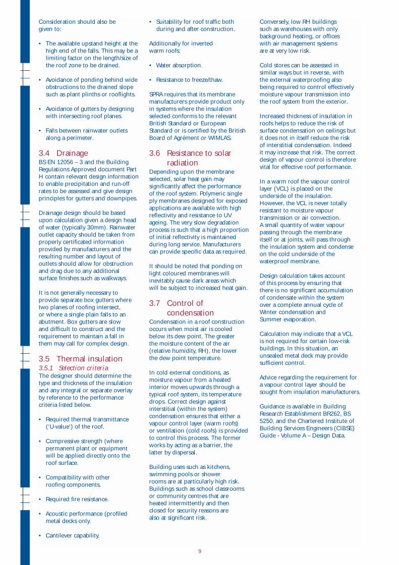
3.2.4 Roof gardens or ‘green’ roofsRoof gardens or ‘green roofs’ typically comprise a roof system of either warm
deck or inverted warm deck construction with drainage, reservoir, filter and
growing medium layers placed above.
Fig. 3.4Green roof - (Warmroof type) (section)
3.3 FallsSince the primary function of the roof
is to exclude water, it is important to
consider how best to direct this into
the drainage system.
Ponding on membrane roofs should
be avoided because:
• It encourages the deposition of dirt
and leaves which can be unsightly,
may obstruct outlets and/or
become a slip hazard.
• In the event of damage, the interior
will suffer a greater water ingress.
• It may cause progressive deflection
of the deck.
• Ice may be a slip or wind hazard.
Independent research (see footnote)
has shown that roofs with extensive
ponding require increased
maintenance input.
Because polymeric single ply
membranes are not affected directly
by standing water, the avoidance of
ponding is not a material-related
issue. Membranes are tested for
water absorption and watertightness
at seams as part of third party
certification. However the
construction process, including the
laying of components and the
forming of seams is clearly facilitated
in dry, well drained conditions.
Roof falls may be created either
during the construction of the deck
or alternatively by the use of tapered
insulation systems. The former has
the advantage that the vapour control
layer will also be to fall and will act
as a second line of defence to water
ingress both during construction
and in service.
BS 6229 states that a minimum
finished fall at any point of 1:80
(1.25%) should be achieved. Since
adjoining roof planes at 1:80 will
meet at a mitre of less than 1:80,
the intended finished fall at such
intersections should be considered
at an early stage.
Design falls should take account
of any potential deflection and
construction tolerances. In the
absence of detailed calculation this
may necessitate design falls of twice
the minimum finished falls (1:40 or
2.5%). Cut-to-falls systems are often
produced to a 1:60 (1.7%) fall
or 1:40 (2.5%) fall.
Footnote: The Assessment of Lifespan Characteristics
and As-built Performance of Flat Roofing Systems: A
summary and recommendations for construction
professionals - BFRC & Napier University June 1994
1
2
3
4
5
6
7
8
9
1
2
3
4
51. Waterproof
membrane
2. Deck
3. Structural
support
4. Thermal
insulation
5. Ceiling
1. Grass,
low-level
plant species
2. Growing
medium
3. Filter layer
4. Drainage/
reservoir layer
5. Protection
layer
6. Waterproof
membrane
7. Thermal
insulation
8. Vapour
control layer
9. Deck8
Consideration should also be
given to:
• The available upstand height at the
high end of the falls. This may be a
limiting factor on the length/size of
the roof zone to be drained.
• Avoidance of ponding behind wide
obstructions to the drained slope
such as plant plinths or rooflights.
• Avoidance of gutters by designing
with intersecting roof planes.
• Falls between rainwater outlets
along a perimeter.
3.4 Drainage BS EN 12056 – 3 and the Building
Regulations Approved document Part
H contain relevant design information
to enable precipitation and run-off
rates to be assessed and give design
principles for gutters and downpipes.
Drainage design should be based
upon calculation given a design head
of water (typically 30mm). Rainwater
outlet capacity should be taken from
properly certificated information
provided by manufacturers and the
resulting number and layout of
outlets should allow for obstruction
and drag due to any additional
surface finishes such as walkways.
It is not generally necessary to
provide separate box gutters where
two planes of roofing intersect,
or where a single plain falls to an
abutment. Box gutters are slow
and difficult to construct and the
requirement to maintain a fall in
them may call for complex design.
3.5 Thermal insulation3.5.1 Selection criteriaThe designer should determine the
type and thickness of the insulation
and any integral or separate overlay
by reference to the performance
criteria listed below.
• Required thermal transmittance
(‘U-value’) of the roof.
• Compressive strength (where
permanent plant or equipment
will be applied directly onto the
roof surface.
• Compatibility with other
roofing components.
• Required fire resistance.
• Acoustic performance (profiled
metal decks only.
• Cantilever capability.
• Suitability for roof traffic both
during and after construction.
Additionally for inverted
warm roofs:
• Water absorption.
• Resistance to freeze/thaw.
SPRA requires that its membrane
manufacturers provide product only
in systems where the insulation
selected conforms to the relevant
British Standard or European
Standard or is certified by the British
Board of Agrément or WIMLAS.
3.6 Resistance to solar
radiationDepending upon the membrane
selected, solar heat gain may
significantly affect the performance
of the roof system. Polymeric single
ply membranes designed for exposed
applications are available with high
reflectivity and resistance to UV
ageing. The very slow degradation
process is such that a high proportion
of initial reflectivity is maintained
during long service. Manufacturers
can provide specific data as required.
It should be noted that ponding on
light coloured membranes will
inevitably cause dark areas which
will be subject to increased heat gain.
3.7 Control of
condensationCondensation in a roof construction
occurs when moist air is cooled
below its dew point. The greater
the moisture content of the air
(relative humidity, RH), the lower
the dew point temperature.
In cold external conditions, as
moisture vapour from a heated
interior moves upwards through a
typical roof system, its temperature
drops. Correct design against
interstitial (within the system)
condensation ensures that either a
vapour control layer (warm roofs)
or ventilation (cold roofs) is provided
to control this process. The former
works by acting as a barrier, the
latter by dispersal.
Building uses such as kitchens,
swimming pools or shower
rooms are at particularly high risk.
Buildings such as school classrooms
or community centres that are
heated intermittently and then
closed for security reasons are
also at significant risk.
Conversely, low RH buildings
such as warehouses with only
background heating, or offices
with air management systems
are at very low risk.
Cold stores can be assessed in
similar ways but in reverse, with
the external waterproofing also
being required to control effectively
moisture vapour transmission into
the roof system from the exterior.
Increased thickness of insulation in
roofs helps to reduce the risk of
surface condensation on ceilings but
it does not in itself reduce the risk
of interstitial condensation. Indeed
it may increase that risk. The correct
design of vapour control is therefore
vital for effective roof performance.
In a warm roof the vapour control
layer (VCL) is placed on the
underside of the insulation.
However, the VCL is never totally
resistant to moisture vapour
transmission or air convection.
A small quantity of water vapour
passing through the membrane
itself or at joints, will pass through
the insulation system and condense
on the cold underside of the
waterproof membrane.
Design calculation takes account
of this process by ensuring that
there is no significant accumulation
of condensate within the system
over a complete annual cycle of
Winter condensation and
Summer evaporation.
Calculation may indicate that a VCL
is not required for certain low-risk
buildings. In this situation, an
unsealed metal deck may provide
sufficient control.
Advice regarding the requirement for
a vapour control layer should be
sought from insulation manufacturers.
Guidance is available in Building
Research Establishment BR262, BS
5250, and the Chartered Institute of
Building Services Engineers (CIBSE)
Guide - Volume A – Design Data.
9
BS 5250 describes a method of
quantifying the accumulation and
removal of condensate during
hypothetical Winter and Summer
conditions respectively. This method
of calculation has also been adopted
for all roof coverings within the
scope of BS6229, which additionally
advises maximum levels of annual
accumulation in Kg.m-2.
All SPRA insulation manufacturer
members offer a calculation service
in respect of both U-values and
condensation risk. However such
calculation is theoretical because it
is based upon steady state conditions
and nominal performance data for
roof components.
Particular consideration should be
given to the following:
Warm roofs
• Avoidance of cold-bridging
across components with high
thermal resistance.
• Avoidance of areas with
reduced thermal resistence
(e.g box gutters).
• Avoidance of air movement
through and across the
roof system.
• Continuity of vapour control layer
at upstands and details generally.
• The effect of penetrations through
the vapour control layer.
Inverted warm roofs
• Avoidance of surface condensation
on lightweight decks.
• Maximum possible drainage
above insulation.
• Avoidance of cold bridging due to
gaps in loose-laid insulation.
Cold deck roofs
• Clear routes for
through-ventilation.
• A minimum 50mm gap between
the underside of the deck and the
top of the insulation.
• Adequate openings for ventilation
at each end of the roof.
3.8 Control of air leakageIn a single ply roofing system,
effective sealing against air leakage
is achieved by either:
• A sealed deck (concrete or steel,
with appropriate sealing at
perimeters and penetrations
by incorporating sealant in the
side and head stitching of the
steel decks).
or (more commonly and easily)
• A vapour control layer which, if
properly sealed to the building
perimeter and all penetrations
should provide a satisfactory seal.
It is anticipated that mechanical
fasteners driven through the
vapour control layer will not affect
permeability significantly because
the insulation is compressed onto
the vapour control layer at each
fastening point.
It is anticipated that whilst the current
requirement is not onerous and is
easy to achieve, it will become steadily
more onerous with each revision of
the Building Regulations.
3.9 Acoustic insulationAcoustic insulation may be achieved
using a combination of insulation
boards in conjunction with perforated
decking, acoustic ceilings or other
sound reduction measures.
The roof structure may alternatively
be required to provide sound
reduction from external sources such
as, heavy traffic or aircraft, which can
be accommodated through the use
of insulation boards in combination
with increasing the unit mass of the
roof construction.
Advice with regards individual
constructions is available from SPRA
insulation manufacturer members.
A single ply membrane will not
itself provide significant acoustic
performance; however, when used
in the correct roof construction
almost any acoustic requirements
can be met without compromising the
integrity of the waterproofing system.
It is generally not advisable to place
external air handling plant directly
on the roof surface for reasons of
satisfactory weatherproofing
(see section 3.15). In lightweight
construction this may also contribute
to sound transmission. However the
ease with which single ply membranes
can be detailed around vibration -
absorbent mountings should
eliminate the need for such practices.
3.10 Compatibility of
componentsThe selection of components within
the roofing system should be
discussed in detail with the
manufacturer of the membrane
to ensure complete compatibility
between components as the incorrect
specification of incompatible
components will lead to premature
failure of the roofing system.
The correct choice of insulation
(where applicable) is important
when fully adhering the
waterproofing, especially when
solvent based adhesives are being
used and the membrane and
insulation manufacturer should
always be consulted when selecting
the insulation.
3.11 Loads3.11.1 WindAt the earliest possible stage, the
wind load acting on the roof should
be calculated as recommended in
BS 6399 : Part 2 1997. Calculation
should be based upon building
height, site elevation above sea
level, site topography, distance
from hills and urban areas, building
design life and roof design. Separate
calculations for different wind
directions may be necessary.
The effect of openings in the building
such as warehouse doors must also
be considered.
The roof and membrane attachment
design will respond to this design
load with appropriate safety factors.
Once design wind load has been
established, the attachment method
for each impermeable layer in the
roof system must be selected to
exceed this load (see 3.14).
It has been established from
experience and confirmed in relevant
British and industry standards that a
partial bond of bitumen, applied
consistently, can resist a maximum
design load of 2.4kN.m-2. The
equivalent for a full bond is taken
as 3.6kN.m-2. However, caution
must be applied where a nominally
full bond is used to secure a
semi-rigid sheet such an insulation
board because a full bond is rarely
achievable in practice.
In designs with high wind load,
supplementary mechanical fasteners
may be required. Special
consideration of design against
wind load should also be applied
where a bitumen sheet vapour control
layer is bonded to the crowns of a
metal deck in a fully-adhered design.
10
3.11.2 Foot traffic and construction process
All materials developed for single ply
roofs are capable of withstanding
occasional, light, foot traffic for
inspection purposes.
Where walkways are to be provided
for servicing roof top equipment or
maintenance, a handrail or fall arrest
system may be a requirement.
Even on non-access roofs, the
construction process itself places
demands upon the resistance of the
system to repeated loads.
Considerations include:
• The distribution of roof access
points and the effect of repeated
loads on the system nearby;
load-spreading protection will
usually be required.
• The location of plant and
the provision of heavy-duty
walkway sheets to protect the
waterproof membrane.
• Provision of load-spreading sheets
below the waterproof membrane
in situations where materials may
be stored or heavy equipment
used, for example to service
roof-mounted equipment.
During construction, the most
effective protection is timber panels
such as plywood or oriented strand
board with taped or linked joints.
The construction sequence should
be reviewed to ensure that heavy
deliveries (for example, a pallet of
coping stones or atrium glazing units)
are not placed on the roof without
special bearers to transfer their load
to the structure. Membrane and
insulation manufacturers should be
consulted in such cases.
3.11.3 Plant and equipmentThe design objective should be the
transfer of loads from permanent
plant and equipment directly to
structure either through a bridging
structure taken to elevations or by
piers penetrating the roof system.
In the latter case, the pier section
must facilitate the waterproofing
process or be constructed with an
integral flashing. For example, it is
very difficult and therefore costly,
to waterproof an I - section
effectively. If equipment dead load
is to be applied to the roof system
the advice of the membrane
manufacturer should be sought
regarding compression resistance
of insulation, and requirements for
separating layers.
3.12 External fire
performanceExternal fire performance of roof
systems is assessed according to BS
476 Part 3 : 1958, where the roofing
system is subjected to fire exposure
from a simulated external burning
brand comprising a gas flame. The
external fire performance is expressed
as a requirement for the whole roof
construction including deck and
covering, characterised by penetration
of fire and spread of flame.
Classification ranges from (highest)
Ext. FAA (external flat, penetration
rating A, spread of flame rating A)
to Ext. FCD (lowest). Note that the
minimum guidance of the Approved
Document still relates to the 1958
test, and not the 1975 version,
which has not been adopted by
the regulators.
Note 2. European tests and fire
classification systems are expected
to be introduced as supplements to
Approved Document B, and
Technical Standards in Scotland,
from 2002 – 2003.
It is anticipated that the new
European Standard (ENV
1187 : 2002) for external fire
exposure of roofs will be
implemented during the life of
this Guide. This test is in three
parts as follows:
• Part 1 To simulate a burning brand
without wind.
• Part 2 To simulate a burning brand
with wind.
• Part 3 To simulate a burning brand
with wind and radiation from an
adjoining burning building.
The Building Regulations will be
amended to incorporate one or more
of these tests based on a new
European classification document
for extenal fire performance, currently
EN 13501-2 (expected 2002).
The existing BS476 reference will
then be withdrawn. A ‘transitional
period’ during which fire test
certificates for existing products
based upon BS476 will be allowed
but all new systems are likely to
require assessment to the new
tests with immediate effect.
The Building Regulations Approved
Document B also makes fire
resistance provisions for where fire
exposure to the underside of the
roof needs to be considered. These
are listed in Table A1 of the approved
document and apply: -
• When the roof and its support
structure are part of an escape
route, including any opening
within 3m of the escape route.
• When the roof performs the
function of a floor.
Building designers should ensure
that the client is aware of the Fire
precautions (Workplace)
Regulations:1997 (As amended),
wherein the employer is required
to undertake the continually review
a risk assessment to ensure that
employees are not placed at risk
from fire. It is recommended that
a fire expert be consulted as part
of this process.
3.13 Lightning protectionThe installation of a well-designed
lightning protection system on a
structure will collect the strike
itself and dissipate it safely to earth.
The design of a lightning protection
system for installation in the
United Kingdom should be in
accordance with BS6651 : 1991.
A harmonised European Standard
is anticipated shortly.
The design process uses a defined
formula to establish the need for
protection based on building location,
structural materials and building use.
If protection is required, early
communication to the lightning
protection supplier and/or contractor
of the roof system components and
method of attachment will avoid
sequencing difficulties as the job
proceeds. Care should be taken
to ensure that
• The detailing of waterproofing at
entry points of the conductor(s)
into the roof is weatherproof
and durable.
• The conductor is visible for
inspection purposes and
not hidden by details or
plant installations.
Note: the ‘Consultants Handbook’was available free of charge fromW.J. Furse, Wilford Road, Nottingham NG2 1EB at the time this Guide went to press.
11
3.14 Methods of
attachment3.14.1 IntroductionThe means of attaching the
waterproof membrane and
thermal insulation to the
substrate must be selected only
after calculation of wind uplift
forces as recommended in
BS 6399: Part 2 1997. If using
this documentation for projects
outside the UK, national codes
of practice must be taken
into consideration.
The three principal options
for attachment of single ply
membranes are:
• Mechanical fastening.
• Adhesion.
• Ballast.
In warm roofs, the thermal insulation
may be attached by the same or by
a different method from the
waterproof membrane. Insulation
for inverted warm roofs is restrained
by the ballast overlay.
The selection of the appropriate
method should be on the basis of
the following criteria:
• Calculated wind load.
• The suitability of the deck to
receive mechanical fasteners.
• The internal relative humidity.
• The extent and complexity of
roof detailing.
• Aesthetic considerations.
• (refurbishment) The condition
of the existing system.
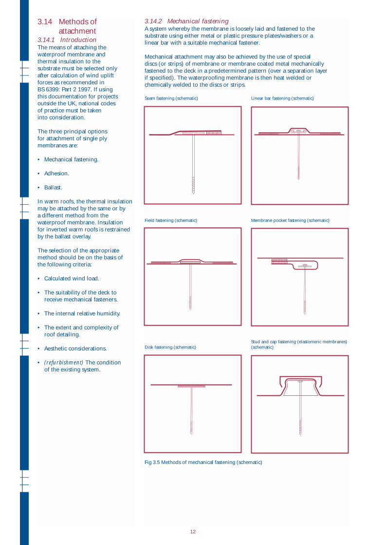
3.14.2 Mechanical fasteningA system whereby the membrane is loosely laid and fastened to the
substrate using either metal or plastic pressure plates/washers or a
linear bar with a suitable mechanical fastener.
Mechanical attachment may also be achieved by the use of special
discs (or strips) of membrane or membrane coated metal mechanically
fastened to the deck in a predetermined pattern (over a separation layer
if specified). The waterproofing membrane is then heat welded or
chemically welded to the discs or strips.
Seam fastening (schematic) Linear bar fastening (schematic)
Field fastening (schematic) Membrane pocket fastening (schematic)
Stud and cap fastening (elastomeric membranes)
Disk fastening (schematic) (schematic)
Fig 3.5 Methods of mechanical fastening (schematic)
12
Mechanical fasteners should not
create significant cold bridge effects
and should be compatible with
other components.
If the remainder of the roof system
is to be bonded it is essential that
the design resistance to wind load
is achieved.
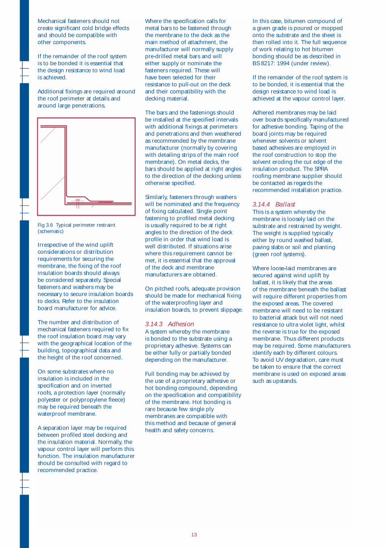
Additional fixings are required around
the roof perimeter at details and
around large penetrations.
Fig 3.6 Typical perimeter restraint
(schematic)
Irrespective of the wind uplift
considerations or distribution
requirements for securing the
membrane, the fixing of the roof
insulation boards should always
be considered separately. Special
fasteners and washers may be
necessary to secure insulation boards
to decks. Refer to the insulation
board manufacturer for advice.
The number and distribution of
mechanical fasteners required to fix
the roof insulation board may vary
with the geographical location of the
building, topographical data and
the height of the roof concerned.
On some substrates where no
insulation is included in the
specification and on inverted
roofs, a protection layer (normally
polyester or polypropylene fleece)
may be required beneath the
waterproof membrane.
A separation layer may be required
between profiled steel decking and
the insulation material. Normally, the
vapour control layer will perform this
function. The insulation manufacturer
should be consulted with regard to
recommended practice.
Where the specification calls for
metal bars to be fastened through
the membrane to the deck as the
main method of attachment, the
manufacturer will normally supply
pre-drilled metal bars and will
either supply or nominate the
fasteners required. These will
have been selected for their
resistance to pull-out on the deck
and their compatibility with the
decking material.
The bars and the fastenings should
be installed at the specified intervals
with additional fixings at perimeters
and penetrations and then weathered
as recommended by the membrane
manufacturer (normally by covering
with detailing strips of the main roof
membrane). On metal decks, the
bars should be applied at right angles
to the direction of the decking unless
otherwise specified.
Similarly, fasteners through washers
will be nominated and the frequency
of fixing calculated. Single point
fastening to profiled metal decking
is usually required to be at right
angles to the direction of the deck
profile in order that wind load is
well distributed. If situations arise
where this requirement cannot be
met, it is essential that the approval
of the deck and membrane
manufacturers are obtained.
On pitched roofs, adequate provision
should be made for mechanical fixing
of the waterproofing layer and
insulation boards, to prevent slippage.
3.14.3 AdhesionA system whereby the membrane
is bonded to the substrate using a
proprietary adhesive. Systems can
be either fully or partially bonded
depending on the manufacturer.
Full bonding may be achieved by
the use of a proprietary adhesive or
hot bonding compound, depending
on the specification and compatibility
of the membrane. Hot bonding is
rare because few single ply
membranes are compatible with
this method and because of general
health and safety concerns.
In this case, bitumen compound of
a given grade is poured or mopped
onto the substrate and the sheet is
then rolled into it. The full sequence
of work relating to hot bitumen
bonding should be as described in
BS 8217: 1994 (under review).
If the remainder of the roof system is
to be bonded, it is essential that the
design resistance to wind load is
achieved at the vapour control layer.
Adhered membranes may be laid
over boards specifically manufactured
for adhesive bonding. Taping of the
board joints may be required
whenever solvents or solvent
based adhesives are employed in
the roof construction to stop the
solvent eroding the cut edge of the
insulation product. The SPRA
roofing membrane supplier should
be contacted as regards the
recommended installation practice.
3.14.4 BallastThis is a system whereby the
membrane is loosely laid on the
substrate and restrained by weight.
The weight is supplied typically
either by round washed ballast,
paving slabs or soil and planting
(green roof systems).
Where loose-laid membranes are
secured against wind uplift by
ballast, it is likely that the areas
of the membrane beneath the ballast
will require different properties from
the exposed areas. The covered
membrane will need to be resistant
to bacterial attack but will not need
resistance to ultra violet light, whilst
the reverse is true for the exposed
membrane. Thus different products
may be required. Some manufacturers
identify each by different colours.
To avoid UV degradation, care must
be taken to ensure that the correct
membrane is used on exposed areas
such as upstands.
13
3.15 DetailingAt an early stage in the design process
an audit of roof geometry should be
carried out to establish what types of
details will be required and whether
they are to be weatherproof
(incorporating an upstand/cover
flashing arrangement) or waterproof
(providing continuous waterproofing
across the detail).
Wherever possible, thermal
performance should be maintained
across a detail to avoid creation of a
cold bridge. Restraint against wind
load and design fire resistance must
also be maintained across details.
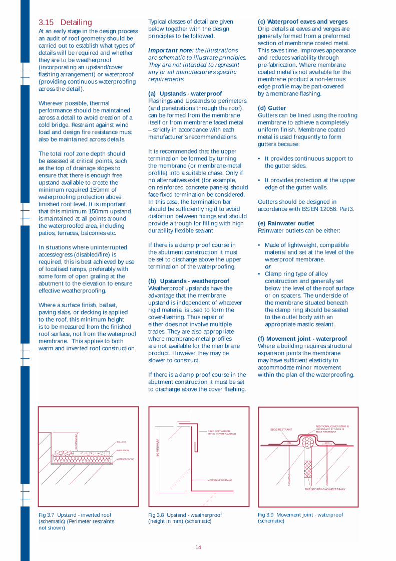
The total roof zone depth should
be assessed at critical points, such
as the top of drainage slopes to
ensure that there is enough free
upstand available to create the
minimum required 150mm of
waterproofing protection above
finished roof level. It is important
that this minimum 150mm upstand
is maintained at all points around
the waterproofed area, including
patios, terraces, balconies etc.
In situations where uninterrupted
access/egress (disabled/fire) is
required, this is best achieved by use
of localised ramps, preferably with
some form of open grating at the
abutment to the elevation to ensure
effective weatherproofing.
Where a surface finish, ballast,
paving slabs, or decking is applied
to the roof, this minimum height
is to be measured from the finished
roof surface, not from the waterproof
membrane. This applies to both
warm and inverted roof construction.
Fig 3.7 Upstand - inverted roof
(schematic) (Perimeter restraints
not shown)
Typical classes of detail are given
below together with the design
principles to be followed.
Important note: the illustrations are schematic to illustrate principles.They are not intended to representany or all manufacturers specificrequirements.
(a) Upstands - waterproofFlashings and Upstands to perimeters,
(and penetrations through the roof),
can be formed from the membrane
itself or from membrane faced metal
– strictly in accordance with each
manufacturer’s recommendations.
It is recommended that the upper
termination be formed by turning
the membrane (or membrane-metal
profile) into a suitable chase. Only if
no alternatives exist (for example,
on reinforced concrete panels) should
face-fixed termination be considered.
In this case, the termination bar
should be sufficiently rigid to avoid
distortion between fixings and should
provide a trough for filling with high
durability flexible sealant.
If there is a damp proof course in
the abutment construction it must
be set to discharge above the upper
termination of the waterproofing.
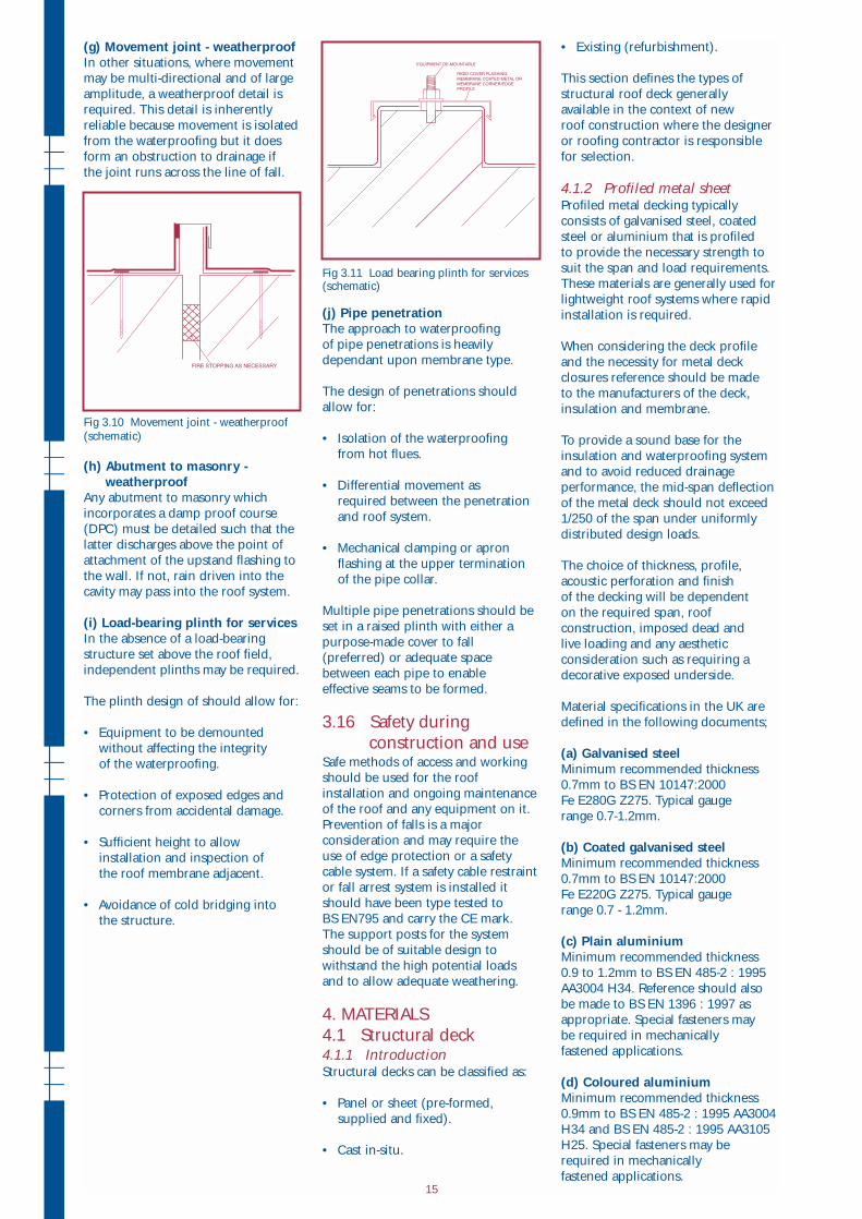
(b) Upstands - weatherproofWeatherproof upstands have the
advantage that the membrane
upstand is independent of whatever
rigid material is used to form the
cover-flashing. Thus repair of
either does not involve multiple
trades. They are also appropriate
where membrane-metal profiles
are not available for the membrane
product. However they may be
slower to construct.
If there is a damp proof course in the
abutment construction it must be set
to discharge above the cover flashing.
Fig 3.8 Upstand - weatherproof (height in mm) (schematic)
(c) Waterproof eaves and vergesDrip details at eaves and verges are
generally formed from a preformed
section of membrane coated metal.
This saves time, improves appearance
and reduces variability through
pre-fabrication. Where membrane
coated metal is not available for the
membrane product a non-ferrous
edge profile may be part-covered
by a membrane flashing.
(d) GutterGutters can be lined using the roofing
membrane to achieve a completely
uniform finish. Membrane coated
metal is used frequently to form
gutters because:
• It provides continuous support to
the gutter sides.
• It provides protection at the upper
edge of the gutter walls.
Gutters should be designed in
accordance with BS EN 12056: Part3.
(e) Rainwater outletRainwater outlets can be either:
• Made of lightweight, compatible
material and set at the level of the
waterproof membrane.
or
• Clamp ring type of alloy
construction and generally set
below the level of the roof surface
or on spacers. The underside of
the membrane situated beneath
the clamp ring should be sealed
to the outlet body with an
appropriate mastic sealant.
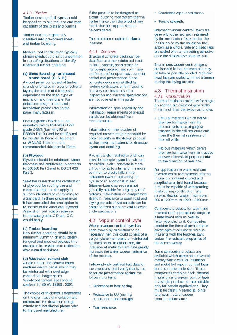
(f) Movement joint - waterproofWhere a building requires structural
expansion joints the membrane
may have sufficient elasticity to
accommodate minor movement
within the plan of the waterproofing.
Fig 3.9 Movement joint - waterproof(schematic)
14
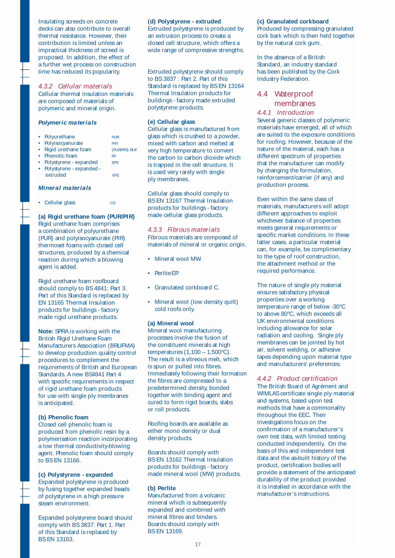
(g) Movement joint - weatherproofIn other situations, where movement
may be multi-directional and of large
amplitude, a weatherproof detail is
required. This detail is inherently
reliable because movement is isolated
from the waterproofing but it does
form an obstruction to drainage if
the joint runs across the line of fall.
Fig 3.10 Movement joint - weatherproof
(schematic)
(h) Abutment to masonry - weatherproof
Any abutment to masonry which
incorporates a damp proof course
(DPC) must be detailed such that the
latter discharges above the point of
attachment of the upstand flashing to
the wall. If not, rain driven into the
cavity may pass into the roof system.
(i) Load-bearing plinth for servicesIn the absence of a load-bearing
structure set above the roof field,
independent plinths may be required.
The plinth design of should allow for:
• Equipment to be demounted
without affecting the integrity
of the waterproofing.
• Protection of exposed edges and
corners from accidental damage.
• Sufficient height to allow
installation and inspection of
the roof membrane adjacent.
• Avoidance of cold bridging into
the structure.
Fig 3.11 Load bearing plinth for services (schematic)
(j) Pipe penetrationThe approach to waterproofing
of pipe penetrations is heavily
dependant upon membrane type.
The design of penetrations should
allow for:
• Isolation of the waterproofing
from hot flues.
• Differential movement as
required between the penetration
and roof system.
• Mechanical clamping or apron
flashing at the upper termination
of the pipe collar.
Multiple pipe penetrations should be
set in a raised plinth with either a
purpose-made cover to fall
(preferred) or adequate space
between each pipe to enable
effective seams to be formed.
3.16 Safety during
construction and useSafe methods of access and working
should be used for the roof
installation and ongoing maintenance
of the roof and any equipment on it.
Prevention of falls is a major
consideration and may require the
use of edge protection or a safety
cable system. If a safety cable restraint
or fall arrest system is installed it
should have been type tested to
BS EN795 and carry the CE mark.
The support posts for the system
should be of suitable design to
withstand the high potential loads
and to allow adequate weathering.
4. MATERIALS
4.1 Structural deck4.1.1 IntroductionStructural decks can be classified as:
• Panel or sheet (pre-formed,
supplied and fixed).
• Cast in-situ.
• Existing (refurbishment).
This section defines the types of
structural roof deck generally
available in the context of new
roof construction where the designer
or roofing contractor is responsible
for selection.
4.1.2 Profiled metal sheetProfiled metal decking typically