A company of MARECHAL ELECTRIC GROUP 4765 W. Oakwood Park Drive • Franklin, WI 53132 • 800.433.7642 • Fax 414.433.2701 • meltric.com PIA CS1000 A CS1000 devices are safe, easy to use, and provide excellent performance and durability. Safety Features • A finger guard provides IP2X protection against accidental contact with live parts. • A locking pin prevents unwanted disconnection. • Five mechanical keying positions with color coding prevent electrically incompatible mating • Advanced Safety Testing: The CS1000 successfully passed Abnormal Overload Tests consisting of making and breaking the devices three times at rated voltage and 150% of full load current. Performance and Durability • Solid silver-nickel contact material provides superior performance and corrosion resistance. • Spring-loaded, butt-style contact technology ensures optimal contact pressure and withstands over 2000 operations. • IP66/IP67 environmental protection for wet, corrosive environments. A company of MARECHAL ELECTRIC GROUP product improvement description Product Improvement Announcement Issue date: 27 April 2016 CS1000 Single Pole Plugs & Connectors Now UL Listed Finger Guard (IP2X) Locking Pawl 1 Removable Unlocking Tool CS1000 plugs and receptacles are now UL listed in accordance with UL1691. CS1000 devices are for use in Non-Load Break applications up to 400A at 600VAC, 600VDC (in North America) and 1000V AC, 1500 VDC (in Europe –CE RATED). NEW Ratings 1002001 Meltric CS1000 400A, 600V 45-34001-P80 RECEPTACLE/CONNECTOR IP66/67 USE WITH 90 DEG C CABLES LISTED E483247 Silver-Nickel Butt-Style Contacts
Transcript
A company of MARECHAL ELECTRIC GROUP 4765 W. Oakwood Park Drive • Franklin, WI 53132 • 800.433.7642 • Fax 414.433.2701 • meltric.comPIA CS1000 A
CS1000 devices are safe, easy to use, and provide excellent performance and durability.
Safety Features
• A finger guard provides IP2X protection against accidental contact with live parts.
• A locking pin prevents unwanted disconnection.
• Five mechanical keying positions with color coding prevent electrically incompatible mating
• Advanced Safety Testing: The CS1000 successfully passed Abnormal Overload Tests consisting of making and breaking the devices three times at rated voltage and 150% of full load current.
Performance and Durability
• Solid silver-nickel contact material provides superior performance and corrosion resistance.
• Spring-loaded, butt-style contact technology ensures optimal contact pressure and withstands over 2000 operations.
• IP66/IP67 environmental protection for wet, corrosive environments.
A company of MARECHAL ELECTRIC GROUP
product improvement description
Product Improvement AnnouncementIssue date: 27 April 2016
CS1000
Single Pole Plugs & Connectors Now UL Listed
Finger Guard (IP2X)
Locking Pawl
1
Removable Unlocking Tool
CS1000 plugs and receptacles are now UL listed in accordance with UL1691. CS1000 devices are for use in Non-Load Break applications up to 400A at 600VAC, 600VDC (in North America) and 1000V AC, 1500 VDC (in Europe –CE RATED).
NEWRating
s
1002001
Meltric CS1000400A, 600V
45-34001-P80RECEPTACLE/CONNECTOR IP66/67USE WITH 90 DEG C CABLES
LISTED E483247Silver-Nickel
Butt-Style Contacts
operating instructions
CS1000
1
Insert the plug partially into amatching receptacle.
2
Slide the key back to retract the locking pin.
Connection Disconnection
3
Apply insertion pressure and rotate the plug a quarter turn clockwise to seat the contacts and engage the locking pin.
Insert the key into the groove on the locking pin.
3
Twist the plug a quarter turn counter clockwise and withdraw it.
Unlocking key and key ring included.
Rotate the plug counterclockwise as needed to position the locking pin 90° from its latch.
2
Locking Pin Latch
2
A company of MARECHAL ELECTRIC GROUP 4765 W. Oakwood Park Drive • Franklin, WI 53132 • 800.433.7642 • Fax 414.433.2701 • meltric.comPIA CS1000 A
1
CS1000
MELTRIC CS1000 Competitive Device
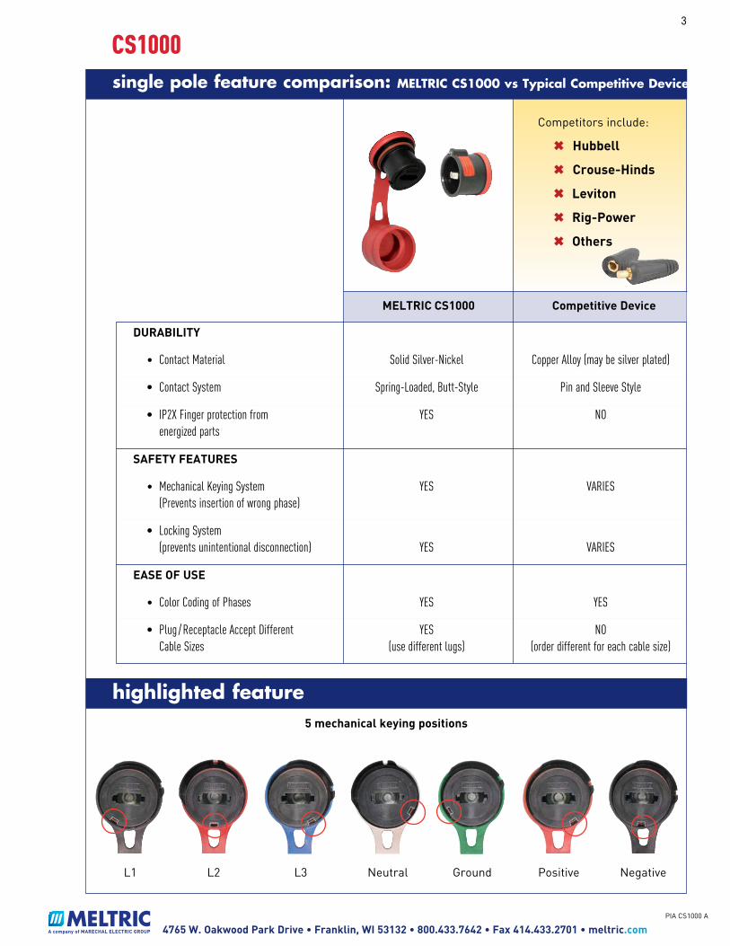
highlighted feature
L1 L2 L3 Neutral Ground Positive Negative
5 mechanical keying positions
Competitors include:
✖ Hubbell
✖ Crouse-Hinds
✖ Leviton
✖ Rig-Power
✖ Others
DURABILITY
• Contact Material Solid Silver-Nickel Copper Alloy (may be silver plated)
• Contact System Spring-Loaded, Butt-Style Pin and Sleeve Style
• IP2X Finger protection from YES NO energized parts
SAFETY FEATURES
• Mechanical Keying System YES VARIES (Prevents insertion of wrong phase)
• Locking System (prevents unintentional disconnection) YES VARIES
EASE OF USE
• Color Coding of Phases YES YES
• Plug / Receptacle Accept Different YES NO Cable Sizes (use different lugs) (order different for each cable size)
3
A company of MARECHAL ELECTRIC GROUP 4765 W. Oakwood Park Drive • Franklin, WI 53132 • 800.433.7642 • Fax 414.433.2701 • meltric.comPIA CS1000 A
single pole feature comparison: MELTRIC CS1000 vs Typical Competitive Device
faq
CS1000
What makes the CS1000 different and better than other single pole devices? CS1000’s offer safety features that competitive single pole devices do not:
1. A finger guard provides IP2X protection from live receptacle parts.
2. Mechanical keying prevents the insertion of plugs with the wrong phasing.
3. A locking pin prevents accidental disconnection.
4. Advanced Safety Testing: The CS1000 successfully passed Abnormal Overload Tests consisting of making and breaking the devices three times at rated voltage and 150% of full load current.
CS1000’s also offer durability advantages because:
1. Solid silver-nickel contacts offer superior conductivity and corrosion resistance.
2. Butt-style contact system ensures optimal contact pressure even after numerous operations.
3. The standard receptacle cap and optional inlet/plug cap keep out contaminants and maintain IP66/67 protection. Where should I sell the CS1000? There are many high amperage applications where the CS1000 is ideal; for example, portable power distribution, backup power generation and OEM skid equipment. We expect the mining, oil, steel, marine/military and entertainment industries to be heavy users. Is the CS1000 CSA listed? The CS1000 is not CSA listed but it is UL listed in accordance with UL 1691. At some time in the future MELTRIC may obtain a CSA listing for the CS1000 but right now we do not have a timeline for that.
Which handle should I order and why? MELTRIC offers two handle options. The standard handle is intended for normal duty and withstands pull out forces up to 100 lbs - this is the lowest cost alternative. The handle with cord grip (mesh) is intended for heavy duty applications and meets UL 1691 require-ments for withstanding a 300 lb pull test.
Why is a key ring included with the unlocking tool? MELTRIC felt that the unlocking tool by itself would be too easy to lose or misplace, so we provide it on a handy “valet” style separable key ring to help the user keep track of it and ensure it is available when needed. We did not feel that it was a good idea to tether the unlocking tool to the plug because it might allow unwanted disconnection by unauthorized personnel.
Can I get a sample for a sales demo?
CS1000 devices are available on a limited basis for sales demonstrations. Please contact your regional manager to request a sales sample when you need one. Is there CS1000 literature available? The CS1000 is in the 2015 catalog but the ratings do not reflect the new UL ratings recently obtained. The 2017 MELTRIC catalog (due to be released in August 2016) will show the new UL ratings. At this point we do not have a flyer available.
StandardHandle
Handle w/Cord Grip (Mesh)
4
A company of MARECHAL ELECTRIC GROUP 4765 W. Oakwood Park Drive • Franklin, WI 53132 • 800.433.7642 • Fax 414.433.2701 • meltric.comPIA CS1000 A
147
CS1000
Ratings – UL
• Amperage 400A Not for Current Interrupting
• Voltage 600 VAC, 600 VDC
• Short Circuit Rating 10kA Withstand Testing was performed with RK1 current limiting fuses sized at at least 100% of the devices ampacity rating.
• Environmental Ratings IP66/IP67
• Temperature Range Min -40°F / Max 140°F
• Wiring Capacity Min 1 / 0 AWG / Max 450 MCM 90°C rated wire must be used
• Listings UL 1691, (CSA pending*)* Contact Customer Service
International Ratings – CE
• Amperage 400A
• Voltage 1000 VAC, 1500 VDC
• Environmental Ratings IP66/IP67
• Temperature Range Min -40°F / Max 140°F • Wiring Capacity Min 1 / 0 AWG / Max 450 MCM
w/Adapter PlateRequired for mountingon panels, walls, etc.
Angles
* One unlocking tool on a “valet” style separable key ring is included with each male inlet.
Installation Accessories
part numbering / pricing – receptacles & inlets
CS10005
A company of MARECHAL ELECTRIC GROUP 4765 W. Oakwood Park Drive • Franklin, WI 53132 • 800.433.7642 • Fax 414.433.2701 • meltric.comPIA CS1000 A
148
HIGH
AM
PACI
TY
CS1000
Dimensions Provided in inches
plug/receptacle
M40
9.09"4.41"
2.68"
1.81"
30° receptacle/angle with plug
Diamètre de perçage
.24"
2.36"
3.03" 1.73" 10.20"
3.7
4"
2.36
"
.28"
4.25
"4.
72"
2.36"
3.98
"
3.86
"
30° inclined receptacle/angle
receptacle
2.20"1.81"4.41"
6.30
"
M40
2.68"
2.32"
1.81"
3.03"
4.25"
2.13"
.20"
3.90"
3.98"
.63"
4.41"
3.74"
2.52"
2.36"
2.36"
.23"
.28"
Dimensions are for reference only and may change depending on accessories used. For precise dimensions contact MELTRIC Engineering.
Crimping lug
CableOutside Diameter Part #
.500 - .625 45-3A753-A
.562 - .688 45-3A753-B
.625 - .750 45-3A753-C
.688 - .812 45-3A753-D
.750 - .875 45-3A753-E
.875 - 1.000 45-3A783-A
1.000 - 1.125 45-3A783-B
1.125 - 1.250 45-3A783-C
1.250 - 1.375 45-3A783-D
CableOutside Diameter Part #
Handle Handle w/Cord Grip (Mesh)
.550 - 1.000 45-3A753
.700 - 1.260 45-3A783
Normal Duty100 lb grip
Heavy Duty300 lb grip
Installation Accessories
Use with angle 30°or direct mount
Use with handleor angle
16.10”
inline connector
Conductor Size
AllowableCurrent (A)
InternalDiameter (in)
Straightw/Terminal
Straight Threaded
1/02 200 .43 45-3A50C 45-3A50D
2/0 250.52 45-3A70C 45-3A70D
3/0 275
4/0 300.58 45-3A95C 45-3A95D
.63 45-3A12C 45-3A12D250 325
350 350 .80 45-4A18C 45-4A18D
450 400 .90 45-4A24C 45-4A24D
1 Lugs to be crimped with Greenlee EK6IDL11 Crimping Tool Dieless 120V CHRG.2 The ground conductor for the CS1000 series devices shall be limited to a maximum size of 1/0 AWG.
part numbering / pricing – accessories
CS10006
A company of MARECHAL ELECTRIC GROUP 4765 W. Oakwood Park Drive • Franklin, WI 53132 • 800.433.7642 • Fax 414.433.2701 • meltric.comPIA CS1000 A
A company of MARECHAL ELECTRIC GROUP 4765 W. Oakwood Park Drive • Franklin, WI 53132 • 800.433.7642 • Fax 414.433.2701 • meltric.comPIA CS1000 A
The color-coded rings of receptacles and connectors include a cap. The color-coded rings of plugs and inlets do not include a cap.
Rated current and voltage markings
It is essential to indicate the current and voltage of the main circuit on the supplied stickers. Apply the stickers on or adjacent to the product so they can easily be seen.
OPERATION
To ensure safe and reliable operation, Meltric plugs and receptacles must be used in accordance with their assigned ratings.
They can only be used in conjunction with mating receptacles or plugs manufactured by Meltric or another licensed producer of products bearing the ™ technology trademark.
Connection
First check to see that the power source is de-energized. DO NOT ENGAGE ON AN ENERGIZED CIRCUIT.
Orient the plug so the contact will fit into the recepta-cle figure 1 . Push the plug partially into the recepta-cle and rotate the plug counterclockwise until it hits a stop figure 2 . Then insert plug fully into receptacle and rotate clockwise about one quarter turn until the locking pin engages into the slot on the receptacle figure 3 .
Disconnection
First check to see that the power source is de-energized. DO NOT DISCONNECT ON AN ENERGIZED CIRCUIT.
Insert unlocking key onto locking pin as shown in figure 4 . Disengage locking pin by sliding unlocking key as shown in figure 5 . When locking pin is re-leased, hold unlocking key in position and twist plug counterclockwise about 30° as shown in figure 6 . After turning, withdraw plug.
PADLOCKING OPTION
Assembly
Place the locking ring as shown:
Operation
Connect the product equipped with the locking ring, insert the shaft and padlock it.
MAINTENANCE
Before inspecting, repairing, or maintaining Meltric products,disconnect electrical power to
the receptacle to eliminate the risk of electrical shock.
Meltric products require little on-going maintenance. However, it is a good practice to periodically perform the following general inspections:
• Check the mounting screws for tightness.
• Verify that the weight of the cable is supported by the strain relief mechanism and not by the ter-minal connections.
• Check the IP gaskets for wear and resiliency. Replace as required.
• Verify the electrical continuity of the ground circuit.
• Check the contact surfaces for cleanliness and pitting.
Deposits of dust or similar foreign materials can be rubbed off the contacts with a clean cloth. Sprays should not be used, as they tend to collect dirt. If any significant pitting of the contacts or other serious damage is observed, the device should be replaced.
Receptacle contacts may be inspected by a qualified electrician. This should only be done with the power off.
MANUFACTURER’S RESPONSIBILITY
Meltric’s responsibility is strictly limited to the repair or replacement of any product that does not conform to the warranty specified in the purchase contract. Meltric shall not be liable for any penalties or conse-quential damages associated with the loss of produc-tion, work, profit or any financial loss incurred by the customer.
Meltric Corporation shall not be held liable when its products are used in conjunction with products not bearing the ™ technology trademark. The use of Meltric products in conjunction with mating devices that are not marked with the ™ technology trademark shall void all warranties on the product.
Meltric Corporation is an ISO 9001 certified company. Its products are designed, manufactured and rated in accordance with applicable UL, CSA and IEC stan-dards. Meltric designs and manufactures its products in accordance with Marechal keying standards established to ensure intermateablility with similarly rated products manufactured by Marechal Electric Group.
INSCS1000 E
5
4
6
3
2
1
Insert
Twist then insert
Twist until pin locks
Retract locking pin
Twist & Remove
Insert un-lock tool
Color-coded ring
Watertightness gasket
Lug
Locking ring
WARNINGDANGERCAUTION
NOTICEADVERTENCIA
DANGERCAUTIONAVISO
WARNINGDANGERCAUTION
NOTICEADVERTENCIA
DANGERCAUTIONAVISO
WARNINGDANGERCAUTION
NOTICEADVERTENCIA
DANGERCAUTIONAVISO
WARNINGDANGERCAUTION
NOTICEADVERTENCIA
DANGERCAUTIONAVISO
Color-coded ring on plug side
Cap with color-coded ring on receptacle side
GENERAL
CS1000 single pole plugs and connectors are de-signed with safety and durability in mind. A finger guard on the receptacle provides IP2X protection from live parts. A locking pin prevents unwanted dis-connection. Each of the phases as well as the neutral and ground are color coded and keyed to prevent improper connection. Please follow the instructions below to ensure the proper installation and use of the product.
There are inherent dangers associated with electrical prod-ucts. Failure to follow safety
precautions can result in serious injury or death. These instructions must be followed to ensure the safe and proper installation, operation and mainte-nance of the Meltric devices. Before installation, dis-connect all sources of power to the circuit to eliminate the risk of electrical shock.
RATINGS
CS1000 plugs and receptacles are UL listed in accor-dance with UL 1691. CS1000 devices are for use in Non-Load Break applications up to 400A at 600VAC, 600VDC (in North America) or 1000VAC, 1500VDC (in Europe – CE rated).
The CS1000 devices are NOT designed or listed for current interruption.
INSTALLATION
These products should be installed by qualified personnel in accordance with all applicable local and national electrical codes.
Before starting, verify that the power is off, that the product ratings are appropriate for the application, and that the conductors meet code requirements and are within the capacities of the lugs noted in Table 1. NOTICE: Connect only copper or copper-clad wire to this device.NOTICE: For correct operation, the power cable must not exert significant force on the product.
Wiring of the main conductor
Strip the conductor by approximately 1-1/8" depending on the lug used. Lugs to be crimped with Greenlee EK6IDL11 Crimping Tool, Dieless 120V CHRG.
Tighten small (through 45-3A12D) Straight Threaded Lugs (Type D) with a 21 mm wrench and large (45-3A18D and up) with a 24 mm wrench. Tighten Straight With Terminal Lug (Type C) screw and washer with a 19 mm socket.
The tightening torque must not be transmitted to the insulated casing. To avoid transmitting
torque to the device when securing the lugs, hold the terminal in place with a 20 mm wrench. Torque both Type C and Type D style lugs to 30 ft-lb. Assembly of the handle
Screw handle onto the product and tighten the cable gland with an appropriate tool. Block the rotation of the handle with the supplied screw. Assemble as shown below.
Assembly with adapter plate
Assemble the adaptor plate on the product and tighten the M40 nut with an appropriate tool. Align tabs and assemble as shown below.
Hole pattern for adapter plate
NOTICE: In order to maintain IP66/67 protection in custom installations, watertight seals must be used under the heads of the four mounting fasteners and they must be retained by a lock washer and nut on the inside of the box or panel. Alternatively, four blind holes can be drilled and threaded to accommodate #8-32 x 5/8" mounting screws. The hole depth must be sufficient to achieve adequate gasket compres-sion.
Assembly on an inclined sleeve (with adapter plate)
Assemble the adapter plate on the inclined sleeve. Do not forget the gasket between the adaptor plate and the inclined sleeve, and between the inclined sleeve and the panel. Assemble as shown below.
When mounting on a wall or panel, position the inlet orreceptacle so that the locking pin or latch is at the top.
Assembly on a panel board
Direct assembly
Assemble the product on the panel board and tighten the M40 nut supplied, with an appropriate tool.The watertightness is achieved by the color-coded ring.
Color coded ring and color-coded ring for the lid
In order to achieve watertightness, do not forget the color-coded ring at the rear of the inlet or receptacle and the panel.
5 Mechanical Keying Postions(North America color codes shown.)
M40 nut
Color-coded ring
Adapter plate
Cap (partial view)
M40 nut Cap with Color-coded ring
Adapter plate
Inclined sleeve
M40 nut
Watertightness gaskets
Color-coded ring
1.89"
.19Ø mount holes
2.25"
1.89"
OPERATING INSTRUCTIONS
A company of MARECHAL ELECTRIC GROUP
Meltric Corporation / 4765 W. Oakwood Park Drive Franklin, WI 53132Tel. : 800 433 7642 / Fax : 414 433 2701 / e-mail : [email protected]
INSCS1000 E
A manufacturer of products using Marechal technology
1. Lugs to be crimped with Greenlee EK6IDL11 Crimping Tool, Dieless 120V CHRG.2. Type W or Compact Cable.3. Intended to be wired with conductors rated 90°C or higher.4. The ground conductor for the CS1000 series devices shall be
limited to a maximum size of 1/0 AWG.5. 444 Locomotive or Diesel Cable to 500MCM Compact Cable.
WARNINGDANGERCAUTION
NOTICEADVERTENCIA
DANGERCAUTIONAVISO
Screw to block rotation
Watertightness gasket
ENGLISH
instructions
CS1000
A company of MARECHAL ELECTRIC GROUP 4765 W. Oakwood Park Drive • Franklin, WI 53132 • 800.433.7642 • Fax 414.433.2701 • meltric.comPIA CS1000 A
The color-coded rings of receptacles and connectors include a cap. The color-coded rings of plugs and inlets do not include a cap.
Rated current and voltage markings
It is essential to indicate the current and voltage of the main circuit on the supplied stickers. Apply the stickers on or adjacent to the product so they can easily be seen.
OPERATION
To ensure safe and reliable operation, Meltric plugs and receptacles must be used in accordance with their assigned ratings.
They can only be used in conjunction with mating receptacles or plugs manufactured by Meltric or another licensed producer of products bearing the ™ technology trademark.
Connection
First check to see that the power source is de-energized. DO NOT ENGAGE ON AN ENERGIZED CIRCUIT.
Orient the plug so the contact will fit into the recepta-cle figure 1 . Push the plug partially into the recepta-cle and rotate the plug counterclockwise until it hits a stop figure 2 . Then insert plug fully into receptacle and rotate clockwise about one quarter turn until the locking pin engages into the slot on the receptacle figure 3 .
Disconnection
First check to see that the power source is de-energized. DO NOT DISCONNECT ON AN ENERGIZED CIRCUIT.
Insert unlocking key onto locking pin as shown in figure 4 . Disengage locking pin by sliding unlocking key as shown in figure 5 . When locking pin is re-leased, hold unlocking key in position and twist plug counterclockwise about 30° as shown in figure 6 . After turning, withdraw plug.
PADLOCKING OPTION
Assembly
Place the locking ring as shown:
Operation
Connect the product equipped with the locking ring, insert the shaft and padlock it.
MAINTENANCE
Before inspecting, repairing, or maintaining Meltric products,disconnect electrical power to
the receptacle to eliminate the risk of electrical shock.
Meltric products require little on-going maintenance. However, it is a good practice to periodically perform the following general inspections:
• Check the mounting screws for tightness.
• Verify that the weight of the cable is supported by the strain relief mechanism and not by the ter-minal connections.
• Check the IP gaskets for wear and resiliency. Replace as required.
• Verify the electrical continuity of the ground circuit.
• Check the contact surfaces for cleanliness and pitting.
Deposits of dust or similar foreign materials can be rubbed off the contacts with a clean cloth. Sprays should not be used, as they tend to collect dirt. If any significant pitting of the contacts or other serious damage is observed, the device should be replaced.
Receptacle contacts may be inspected by a qualified electrician. This should only be done with the power off.
MANUFACTURER’S RESPONSIBILITY
Meltric’s responsibility is strictly limited to the repair or replacement of any product that does not conform to the warranty specified in the purchase contract. Meltric shall not be liable for any penalties or conse-quential damages associated with the loss of produc-tion, work, profit or any financial loss incurred by the customer.
Meltric Corporation shall not be held liable when its products are used in conjunction with products not bearing the ™ technology trademark. The use of Meltric products in conjunction with mating devices that are not marked with the ™ technology trademark shall void all warranties on the product.
Meltric Corporation is an ISO 9001 certified company. Its products are designed, manufactured and rated in accordance with applicable UL, CSA and IEC stan-dards. Meltric designs and manufactures its products in accordance with Marechal keying standards established to ensure intermateablility with similarly rated products manufactured by Marechal Electric Group.
INSCS1000 E
5
4
6
3
2
1
Insert
Twist then insert
Twist until pin locks
Retract locking pin
Twist & Remove
Insert un-lock tool
Color-coded ring
Watertightness gasket
Lug
Locking ring
WARNINGDANGERCAUTION
NOTICEADVERTENCIA
DANGERCAUTIONAVISO
WARNINGDANGERCAUTION
NOTICEADVERTENCIA
DANGERCAUTIONAVISO
WARNINGDANGERCAUTION
NOTICEADVERTENCIA
DANGERCAUTIONAVISO
WARNINGDANGERCAUTION
NOTICEADVERTENCIA
DANGERCAUTIONAVISO
Color-coded ring on plug side
Cap with color-coded ring on receptacle side
GENERAL
CS1000 single pole plugs and connectors are de-signed with safety and durability in mind. A finger guard on the receptacle provides IP2X protection from live parts. A locking pin prevents unwanted dis-connection. Each of the phases as well as the neutral and ground are color coded and keyed to prevent improper connection. Please follow the instructions below to ensure the proper installation and use of the product.
There are inherent dangers associated with electrical prod-ucts. Failure to follow safety
precautions can result in serious injury or death. These instructions must be followed to ensure the safe and proper installation, operation and mainte-nance of the Meltric devices. Before installation, dis-connect all sources of power to the circuit to eliminate the risk of electrical shock.
RATINGS
CS1000 plugs and receptacles are UL listed in accor-dance with UL 1691. CS1000 devices are for use in Non-Load Break applications up to 400A at 600VAC, 600VDC (in North America) or 1000VAC, 1500VDC (in Europe – CE rated).
The CS1000 devices are NOT designed or listed for current interruption.
INSTALLATION
These products should be installed by qualified personnel in accordance with all applicable local and national electrical codes.
Before starting, verify that the power is off, that the product ratings are appropriate for the application, and that the conductors meet code requirements and are within the capacities of the lugs noted in Table 1. NOTICE: Connect only copper or copper-clad wire to this device.NOTICE: For correct operation, the power cable must not exert significant force on the product.
Wiring of the main conductor
Strip the conductor by approximately 1-1/8" depending on the lug used. Lugs to be crimped with Greenlee EK6IDL11 Crimping Tool, Dieless 120V CHRG.
Tighten small (through 45-3A12D) Straight Threaded Lugs (Type D) with a 21 mm wrench and large (45-3A18D and up) with a 24 mm wrench. Tighten Straight With Terminal Lug (Type C) screw and washer with a 19 mm socket.
The tightening torque must not be transmitted to the insulated casing. To avoid transmitting
torque to the device when securing the lugs, hold the terminal in place with a 20 mm wrench. Torque both Type C and Type D style lugs to 30 ft-lb. Assembly of the handle
Screw handle onto the product and tighten the cable gland with an appropriate tool. Block the rotation of the handle with the supplied screw. Assemble as shown below.
Assembly with adapter plate
Assemble the adaptor plate on the product and tighten the M40 nut with an appropriate tool. Align tabs and assemble as shown below.
Hole pattern for adapter plate
NOTICE: In order to maintain IP66/67 protection in custom installations, watertight seals must be used under the heads of the four mounting fasteners and they must be retained by a lock washer and nut on the inside of the box or panel. Alternatively, four blind holes can be drilled and threaded to accommodate #8-32 x 5/8" mounting screws. The hole depth must be sufficient to achieve adequate gasket compres-sion.
Assembly on an inclined sleeve (with adapter plate)
Assemble the adapter plate on the inclined sleeve. Do not forget the gasket between the adaptor plate and the inclined sleeve, and between the inclined sleeve and the panel. Assemble as shown below.
When mounting on a wall or panel, position the inlet orreceptacle so that the locking pin or latch is at the top.
Assembly on a panel board
Direct assembly
Assemble the product on the panel board and tighten the M40 nut supplied, with an appropriate tool.The watertightness is achieved by the color-coded ring.
Color coded ring and color-coded ring for the lid
In order to achieve watertightness, do not forget the color-coded ring at the rear of the inlet or receptacle and the panel.
5 Mechanical Keying Postions(North America color codes shown.)
M40 nut
Color-coded ring
Adapter plate
Cap (partial view)
M40 nut Cap with Color-coded ring
Adapter plate
Inclined sleeve
M40 nut
Watertightness gaskets
Color-coded ring
1.89"
.19Ø mount holes
2.25"
1.89"
OPERATING INSTRUCTIONS
A company of MARECHAL ELECTRIC GROUP
Meltric Corporation / 4765 W. Oakwood Park Drive Franklin, WI 53132Tel. : 800 433 7642 / Fax : 414 433 2701 / e-mail : [email protected]
INSCS1000 E
A manufacturer of products using Marechal technology
1. Lugs to be crimped with Greenlee EK6IDL11 Crimping Tool, Dieless 120V CHRG.2. Type W or Compact Cable.3. Intended to be wired with conductors rated 90°C or higher.4. The ground conductor for the CS1000 series devices shall be
limited to a maximum size of 1/0 AWG.5. 444 Locomotive or Diesel Cable to 500MCM Compact Cable.