OPERATION MANUAL VENTO Ergo A50 Pro VENTO Ergo A50 S Pro VENTO Ergo A50-1 Pro VENTO Ergo A50-1 S Pro SINGLE-ROOM REVERSIBLE UNIT WITH HEAT AND HUMIDITY RECOVERY VENTO_Ergo_A50_Pro_v3(5)_EN.indd 1 10.08.2015 8:22:06
Transcript
OPERATION MANUAL
VENTO Ergo A50 ProVENTO Ergo A50 S ProVENTO Ergo A50-1 ProVENTO Ergo A50-1 S Pro
SINGLE-ROOM REVERSIBLE UNIT WITH HEAT AND HUMIDITY RECOVERY
VENTO Ergo A50/50-1 ProBLAUBERG Company is happy to offer your attention a new high-quality
single-room reversible unit with heat and humidity recovery VENTO Ergo A50 Pro. The solid team of high-qualified professionals with many years of working experience, technological innovations in design and production, high-quality components and materials from the top worldwide producers have become the precondition for the best energy saving unit in its class.
data sheets, operation and mounting guidelines, safety precautions and warnings for safe and correct operation of the unit.
GENERALThe single-room unit is designed for efficient energy saving supply and
exhaust ventilation of flats, houses, cottages and other small premises. The heat recovery technology is used to minimize ventilation heat losses.The unit is equipped with a high-tech ceramic heat exchanger that
provides the utilization of extract air heat energy for warming up of filtered supply air flow. The heat recovery efficiency of the heat exchanger is up to 91%.
The unit is designed for indoor application with the ambient temperature ranging from -20 °C up to +50 °C and relative humidity up to 80%.
The unit is designed for external through-the-wall installation. The unit is designed for continuous operation always connected to power mains.
The unit is allowed for operation only after final mounting, that includes installation of protecting devices in compliance with DIN EN ISO 13875 (DIN EN ISO 12100) as well as other construction safety equipment.
The unit design is regularly improved, so some models may slightly differ from those ones described in this operation manual.
SAFETY RULESThe unit complies with the requirements according to the EU norms
and directives, to the relevant EU-Low Voltage Equipment Directives, EU-Directives on Electromagnetic Compatibility.
All operations related to the unit electrical connections, servicing and repair works are allowed only after the fan disconnection from power mains.
All mounting and servicing operations are allowed for duly qualified electricians with valid electrical work permit for electric operations at the units up to 1000 V after careful study of the present operation manual.
The unit must be grounded! Please follow the safety regulations and working instructions (DIN EN 50
110, IEC 364).Make sure the impeller and the casing are not damaged before
connecting the unit to power mains. The casing internals must be free of any foreign objects which can damage the impeller blades.
Disconnect the unit from power mains prior to any operations related to the unit servicing and repair works.
Misuse of the product or any unauthorized modification are not allowed. The unit is designed for connection to AC single-phase power mains, see
«Technical Data». The unit is rated for permanent operation during non-stop power supply.
Take steps to prevent ingress of smoke, carbon monoxide and other combustion products into the room through open chimney flues or other
fire-protection devices. Sufficient air supply must be provided for proper combustion and exhaust of gases through the chimney of fuel burning equipment to prevent back drafting. The maximum permitted pressure difference per living units is 4 Pa.
The air must not contain any dust or other solid impurities, sticky substances or fibrous materials. The unit is not designed for use in an inflammable and explosive medium.
Do not close or block the unit intake or exhaust vent not to disturb the normal air passage. Do not sit on the unit and do not put objects on the unit.
In case of unusual sounds, smoke disconnect the unit from power supply and contact the service centre.
Follow the operation manual guidelines to ensure trouble-free operation and long service life of the unit.
Hazardous parts access and water ingress protection standard IP24.
STORAGE AND TRANSPORTATION RULESTransportation of the unit is allowed by any vehicle provided the unit is
transported in the original package and is protected against weather and mechanical damages.
Use hoist machinery for handling and transportation to prevent possible mechanical damages of the unit. Fulfil the requirements for transportation of the specified cargo type during cargo-handling operations.
Store the unit in a dry and cool place in the original packing.The storage environment must not be subjected to any aggressive and/
or chemical evaporations, admixtures, foreign objects that may provoke corrosion and damage connection tightness.
Store the unit in an environment with minimized risk of mechanical damages, temperature and humidity fluctuations.
Do not expose the unit to the temperatures below +10 °C and above +40 °C .
Connection of the unit to power mains is allowed after the unit has been kept indoor for minimum two hours.
MANUFACTURER’S WARRANTYThe product complies with the requirements according to the EU norms
and directives, to the relevant EU-Low Voltage Equipment Directives, EU-Directives on Electromagnetic Compatibility.
We hereby declare that the following product complies with the essential protection requirements of Electromagnetic Council Directive 2004/108/EC, 89/336/EEC and Low Voltage Directive 2006/95/EC, 73/23/EEC and CE-marking Directive 93/68/EEC on the approximation of the laws of the Member States relating to electromagnetic compatibility.
The manufacturer hereby warrants normal operation of the product over the period of 2 years from the retail sale date provided observance of the installation and operation regulations.
In case of failure due to manufacturing fault during the warranty period the consumer has the right to exchange it.
If case of no confirmation of the sale date, the warranty period shall be calculated from the manufacturing date.
The replacement is offered by the Seller. The manufacturer shall not be liable for any damage resulting from any
misuse of or gross mechanical interference with the unit.Fulfil the operation manual requirements to ensure a trouble-free and
long service life of the unit.
WARNINGDo not dispose in domestic waste. The unit contains in part material that can be
recycled and in part substances that should not end up as domestic waste.
Dispose of the unit once it has reached the end of its working life according to the regulations valid where you are.
ATTENTIONThe product is not allowed for use by children and persons with reduced
physical, mental or sensory capacities, without proper practical experience or expertise, unless they are controlled or instructed on the product opera-tion by the person(s) responsible for their safety. Supervise the children and do not let them play with the product.
www.blaubergventilatoren.deVENTO Ergo A50/50-1 Pro
DESIGN AND OPERATING LOGIC
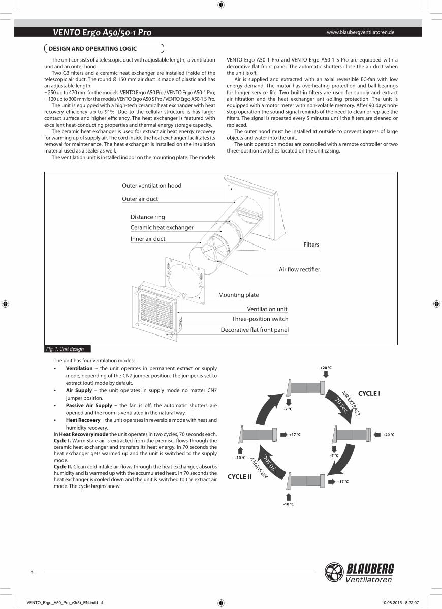
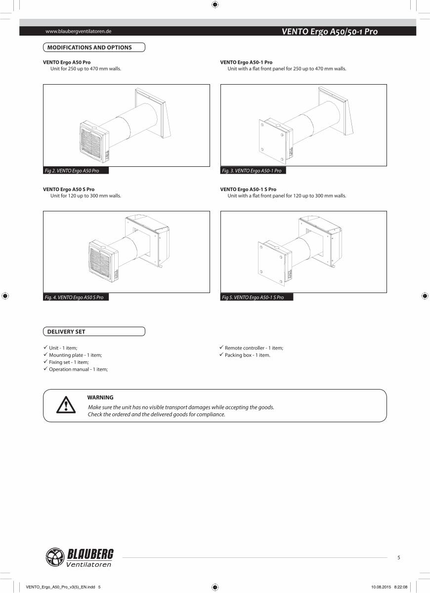
The unit consists of a telescopic duct with adjustable length, a ventilation unit and an outer hood.
Two G3 filters and a ceramic heat exchanger are installed inside of the telescopic air duct. The round Ø 150 mm air duct is made of plastic and has an adjustable length:– 250 up to 470 mm for the models VENTO Ergo A50 Pro / VENTO Ergo A50-1 Pro;– 120 up to 300 mm for the models VENTO Ergo A50 S Pro / VENTO Ergo A50-1 S Pro.
The unit is equipped with a high-tech ceramic heat exchanger with heat recovery efficiency up to 91%. Due to the cellular structure is has larger contact surface and higher efficiency. The heat exchanger is featured with excellent heat-conducting properties and thermal energy storage capacity.
The ceramic heat exchanger is used for extract air heat energy recovery for warming up of supply air. The cord inside the heat exchanger facilitates its removal for maintenance. The heat exchanger is installed on the insulation material used as a sealer as well.
The ventilation unit is installed indoor on the mounting plate. The models
VENTO Ergo A50-1 Pro and VENTO Ergo A50-1 S Pro are equipped with a decorative flat front panel. The automatic shutters close the air duct when the unit is off.
Air is supplied and extracted with an axial reversible EC-fan with low energy demand. The motor has overheating protection and ball bearings for longer service life. Two built-in filters are used for supply and extract air filtration and the heat exchanger anti-soiling protection. The unit is equipped with a motor meter with non-volatile memory. After 90 days non-stop operation the sound signal reminds of the need to clean or replace the filters. The signal is repeated every 5 minutes until the filters are cleaned or replaced.
The outer hood must be installed at outside to prevent ingress of large objects and water into the unit.
The unit operation modes are controlled with a remote controller or two three-position switches located on the unit casing.
Outer ventilation hood
Outer air duct
Inner air duct
Ceramic heat exchanger
Distance ring
Filters
Air �ow recti�er
Ventilation unit
Decorative �at front panel
Three-position switch
Mounting plate
Fig. 1. Unit design
The unit has four ventilation modes:• Ventilation – the unit operates in permanent extract or supply
mode, depending of the CN7 jumper position. The jumper is set to extract (out) mode by default.
• Air Supply – the unit operates in supply mode no matter CN7 jumper position.
• Passive Air Supply – the fan is off, the automatic shutters are opened and the room is ventilated in the natural way.
• Heat Recovery – the unit operates in reversible mode with heat and humidity recovery.
In Heat Recovery mode the unit operates in two cycles, 70 seconds each. Cycle I. Warm stale air is extracted from the premise, flows through the ceramic heat exchanger and transfers its heat energy. In 70 seconds the heat exchanger gets warmed up and the unit is switched to the supply mode.Cycle II. Clean cold intake air flows through the heat exchanger, absorbs humidity and is warmed up with the accumulated heat. In 70 seconds the heat exchanger is cooled down and the unit is switched to the extract air mode. The cycle begins anew.
ATTENTIONRead the operation manual prior to any electric installations. Connection of the unit to power mains is allowed by qualified professionals.
4. Connect the mounting plate according to the wiring diagram, refer to the section Connection to Power Mains, page 10. Prepare four fastening holes and fix the mounting plate on the wall with fours 4x40 screws and 6x40 dowels (included into the delivery set). Align the telescopic air duct with respect to the mounting plate and fill the gaps between the wall and the telescopic air duct with a mounting foam. The telescopic air duct must not protrude beyond the surface of the mounting plate.
The unit is designed for through-the-wall mounting in the building outer wall. Mounting sequence:1. Prepare a round core hole through the outer wall. The size is shown in the figure 7. 2. After the core hole is ready cut out a 25 mm deep recess for laying of the cables and the contact sockets connected to the mounting plate. The recess
shape is shown in fig. 8.While mounting several connected in series units provide a recess for the cable layout during the hole preparation to enable series connection of several
units.
170
Fig. 7. Size of the core hole
max 200
max 90
R100
Fig. 8. Recess size and shape
3. Install the telescopic air duct in the wall. The protruding telescopic air duct section on outer wall side must be equal to the distance A, fig. 9:
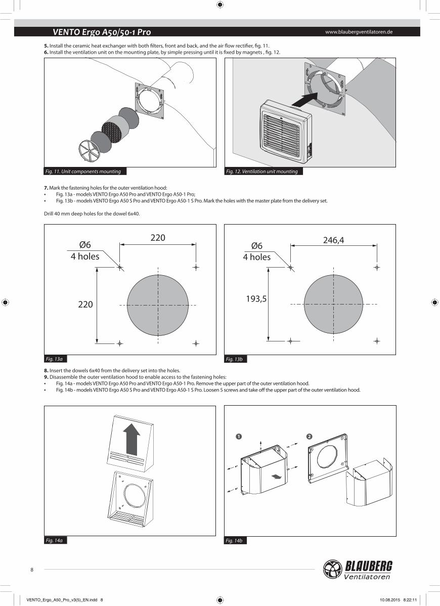
www.blaubergventilatoren.deVENTO Ergo A50/50-1 Pro5. Install the ceramic heat exchanger with both filters, front and back, and the air flow rectifier, fig. 11. 6. Install the ventilation unit on the mounting plate, by simple pressing until it is fixed by magnets , fig. 12.
7. Mark the fastening holes for the outer ventilation hood:• Fig. 13a - models VENTO Ergo A50 Pro and VENTO Ergo A50-1 Pro;• Fig. 13b - models VENTO Ergo A50 S Pro and VENTO Ergo A50-1 S Pro. Mark the holes with the master plate from the delivery set.
Drill 40 mm deep holes for the dowel 6x40.
8. Insert the dowels 6x40 from the delivery set into the holes. 9. Disassemble the outer ventilation hood to enable access to the fastening holes:• Fig. 14a - models VENTO Ergo A50 Pro and VENTO Ergo A50-1 Pro. Remove the upper part of the outer ventilation hood. • Fig. 14b - models VENTO Ergo A50 S Pro and VENTO Ergo A50-1 S Pro. Loosen 5 screws and take off the upper part of the outer ventilation hood.
10. Fix the back part of the outer hood on the wall:• Fig. 15a - models VENTO Ergo A50 Pro and VENTO Ergo A50-1 Pro. Fix the back part of the outer ventilation hood to the wall with the screws 4x40 from the delivery
set. • Fig. 15b -models VENTO Ergo A50 S Pro and VENTO Ergo A50-1 S Pro. Fix the back part of the outer ventilation hood to the wall with the screws 4x40 from the
delivery set.
11. Install the upper part of the outer ventilation hood:• Fig. 16a − models VENTO Ergo A50 Pro and VENTO Ergo A50-1 Pro;• Fig. 16b − models VENTO Ergo A50 S Pro and VENTO Ergo A50-1 S Pro.
www.blaubergventilatoren.deVENTO Ergo A50/50-1 Pro
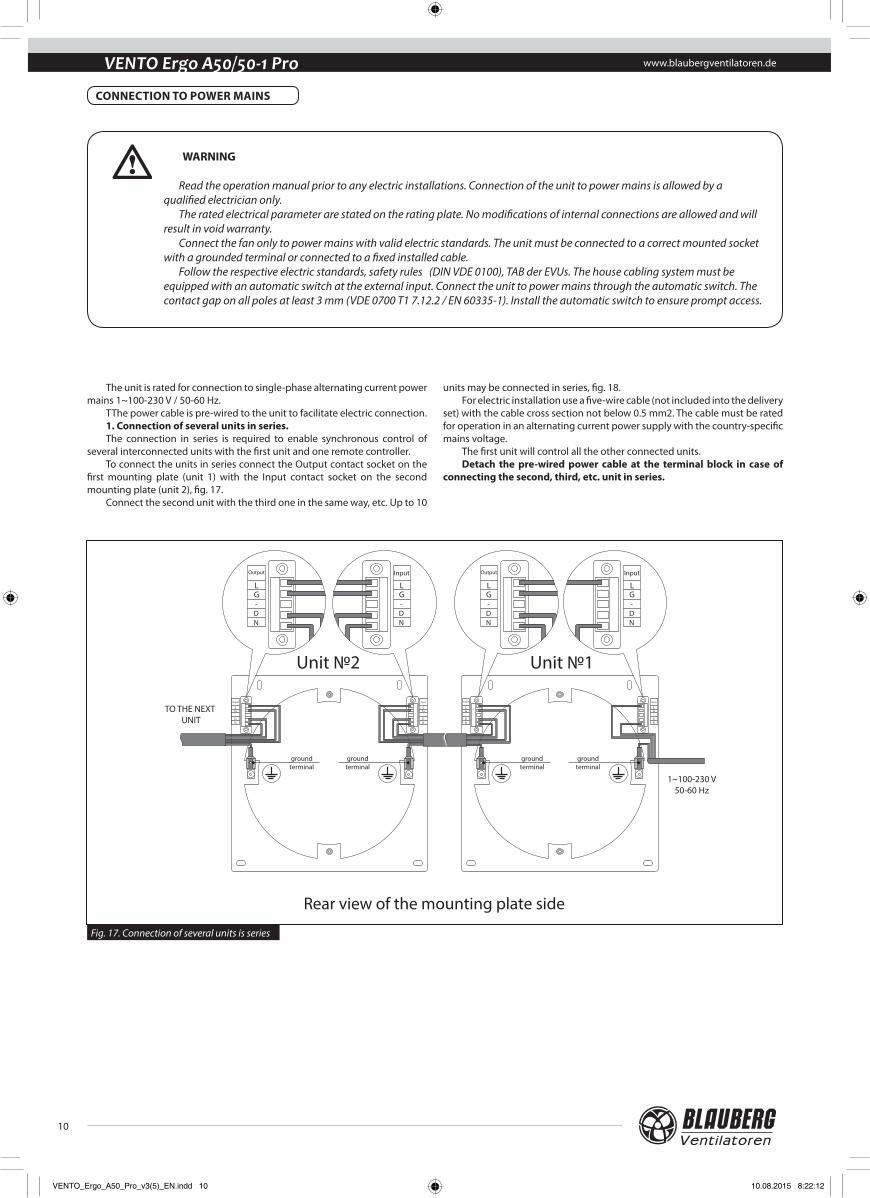
The unit is rated for connection to single-phase alternating current power mains 1~100-230 V / 50-60 Hz.
TThe power cable is pre-wired to the unit to facilitate electric connection. 1. Connection of several units in series.The connection in series is required to enable synchronous control of
several interconnected units with the first unit and one remote controller. To connect the units in series connect the Output contact socket on the
first mounting plate (unit 1) with the Input contact socket on the second mounting plate (unit 2), fig. 17.
Connect the second unit with the third one in the same way, etc. Up to 10
units may be connected in series, fig. 18. For electric installation use a five-wire cable (not included into the delivery
set) with the cable cross section not below 0.5 mm2. The cable must be rated for operation in an alternating current power supply with the country-specific mains voltage.
The first unit will control all the other connected units. Detach the pre-wired power cable at the terminal block in case of
connecting the second, third, etc. unit in series.
Unit №2 Unit №1
ground terminal
ground terminal
ground terminal
ground terminal
1~100-230 V50-60 Hz
TO THE NEXT UNIT
Rear view of the mounting plate side
Input
LG-DN
Output
LG-DN
Input
LG-DN
Output
LG-DN
Output
LG-DN
Input
LG-DN
Input
LG-DN
Output
LG-DN
CONNECTION TO POWER MAINS
WARNING
Read the operation manual prior to any electric installations. Connection of the unit to power mains is allowed by a qualified electrician only.
The rated electrical parameter are stated on the rating plate. No modifications of internal connections are allowed and will result in void warranty.
Connect the fan only to power mains with valid electric standards. The unit must be connected to a correct mounted socket with a grounded terminal or connected to a fixed installed cable.
Follow the respective electric standards, safety rules (DIN VDE 0100), TAB der EVUs. The house cabling system must be equipped with an automatic switch at the external input. Connect the unit to power mains through the automatic switch. The contact gap on all poles at least 3 mm (VDE 0700 T1 7.12.2 / EN 60335-1). Install the automatic switch to ensure prompt access.
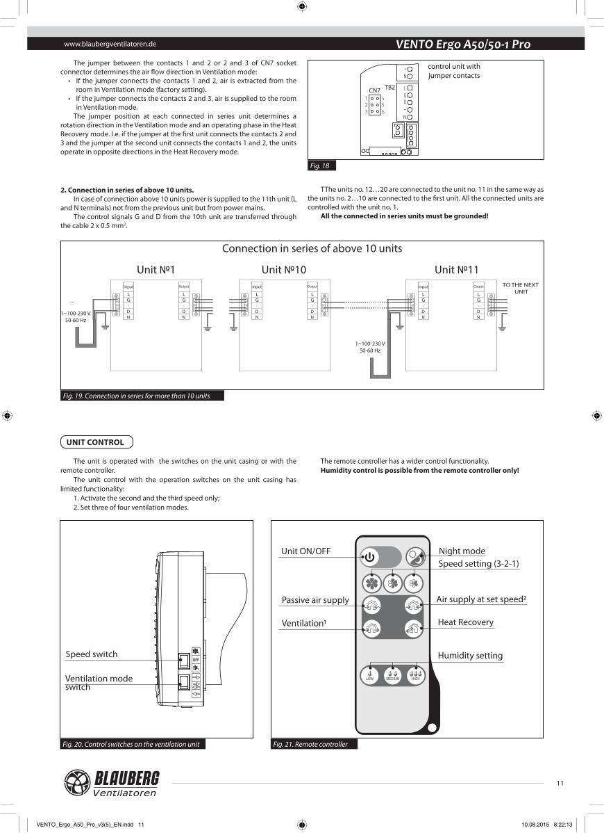
VENTO Ergo A50/50-1 ProThe jumper between the contacts 1 and 2 or 2 and 3 of CN7 socket
connector determines the air flow direction in Ventilation mode:• If the jumper connects the contacts 1 and 2, air is extracted from the
room in Ventilation mode (factory setting). • If the jumper connects the contacts 2 and 3, air is supplied to the room
in Ventilation mode.The jumper position at each connected in series unit determines a
rotation direction in the Ventilation mode and an operating phase in the Heat Recovery mode. I.e. if the jumper at the first unit connects the contacts 2 and 3 and the jumper at the second unit connects the contacts 1 and 2, the units operate in opposite directions in the Heat Recovery mode.
L
N
GD+
+
N
L
N
GD+
+
N
control unit with jumper contacts
TB2CN7123
456
Output
LG-DN
Input
LG-DN
Output
LG-DN
Input
LG-DN
Output
LG-DN
Input
LG-DN
1~100-230 V50-60 Hz
1~100-230 V50-60 Hz
Unit №10
Connection in series of above 10 units
Unit №11Unit №1TO THE NEXT
UNIT
2. Connection in series of above 10 units.In case of connection above 10 units power is supplied to the 11th unit (L
and N terminals) not from the previous unit but from power mains.The control signals G and D from the 10th unit are transferred through
the cable 2 x 0.5 mm2.
TThe units no. 12…20 are connected to the unit no. 11 in the same way as the units no. 2…10 are connected to the first unit. All the connected units are controlled with the unit no. 1.
All the connected in series units must be grounded!
Fig. 18
Fig. 19. Connection in series for more than 10 units
Fig. 20. Control switches on the ventilation unit Fig. 21. Remote controller
The unit is operated with the switches on the unit casing or with the remote controller.
The unit control with the operation switches on the unit casing has limited functionality:
1. Activate the second and the third speed only;2. Set three of four ventilation modes.
The remote controller has a wider control functionality. Humidity control is possible from the remote controller only!
www.blaubergventilatoren.deVENTO Ergo A50/50-1 Pro
Function Button
1 Unit ON/OFF
2 Night mode
ActivationActivation of the Night Mode is confirmed with a long sound signal. If the Night Mode function is activated the unit is switched to first speed when the light is off in the night.
DeactivationExit from the Night Mode is confirmed by a short sound signal.
3 Speed setting
First speed - slow
Second speed
Third speed - maximum speed
4 Operation mode setting
Changeover to Passive Supply.Natural ventilation of a room when the fan is off.
Changeover to Air Supply Mode.Air is supplied to the room at the set speed. All the connected in series units operate in Air Supply Mode no matter of the CN7 jumper position.
Changeover to the Ventilation Mode.All the connected in series units operate either in Air Extract or Air Supply Mode depending on the CN7 jumper position. By default the jumper is set to Air Extract mode.
Changeover to Heat Recovery Mode.The unit operates 70 seconds in Air Supply Mode, then 70 seconds in Air Extract Mode with heat and humidity recovery.
5Humidity control (available only for Heat Recovery mode).If the indoor humidity exceeds the set point, the unit switches to the third speed. If the humidity is within ±5%, the unit operates at the second speed. If the indoor humidity is below the set point, the unit is switched to the minimum speed.
45%
55%
65%
Operation with the remote controller
Turn the switches on the ventilation unit to OFF position prior to using the remote controller.
Speed switch positions: − third speed. The unit operates with maximum air flow.
− the fan is off. The unit does not operate. The shutters are closed.
− second speed. The unit operates with 50% air capacity.
Ventilation mode switch positions: − Ventilation mode. All the connected in series units operate either
in extract or supply mode with no reference to the CN7 jumper position. By default the jumper is set to extract mode.
− Heat Recovery mode. The unit operates in cycles in reversible mode with heat and humidity recovery. The unit operates 70 seconds in air supply mode and then switches to air extract mode. − Supply mode. All the connected in series units operate in supply
mode with no reference to the CN7 jumper position.
1 - operation mode of all the connected in series units is determined by the CN7 jumper position.
2 - all the connected in series units operate in supply mode with no reference to the CN7 jumper position.
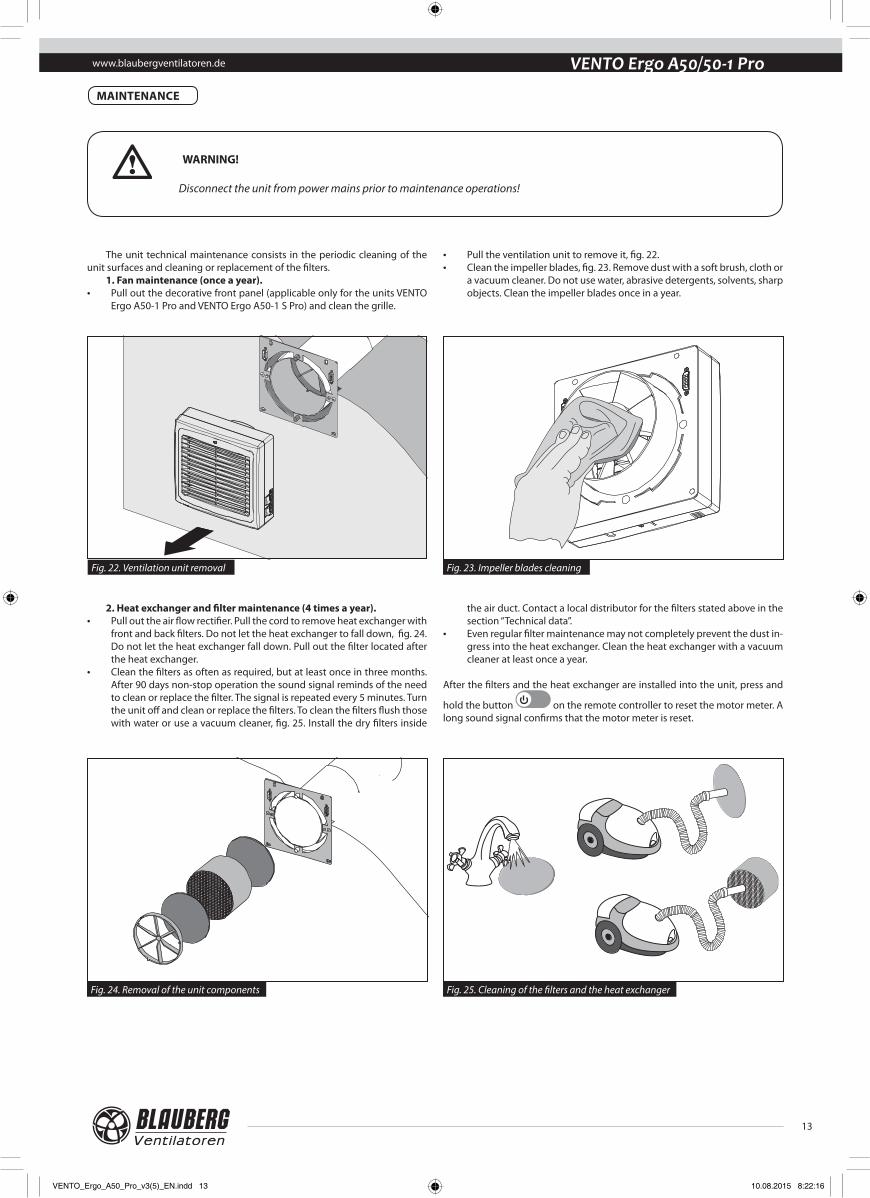
The unit technical maintenance consists in the periodic cleaning of the unit surfaces and cleaning or replacement of the filters.
1. Fan maintenance (once a year).• Pull out the decorative front panel (applicable only for the units VENTO
Ergo A50-1 Pro and VENTO Ergo A50-1 S Pro) and clean the grille.
• Pull the ventilation unit to remove it, fig. 22. • Clean the impeller blades, fig. 23. Remove dust with a soft brush, cloth or
a vacuum cleaner. Do not use water, abrasive detergents, solvents, sharp objects. Clean the impeller blades once in a year.
2. Heat exchanger and filter maintenance (4 times a year).• Pull out the air flow rectifier. Pull the cord to remove heat exchanger with
front and back filters. Do not let the heat exchanger to fall down, fig. 24. Do not let the heat exchanger fall down. Pull out the filter located after the heat exchanger.
• Clean the filters as often as required, but at least once in three months. After 90 days non-stop operation the sound signal reminds of the need to clean or replace the filter. The signal is repeated every 5 minutes. Turn the unit off and clean or replace the filters. To clean the filters flush those with water or use a vacuum cleaner, fig. 25. Install the dry filters inside
the air duct. Contact a local distributor for the filters stated above in the section “Technical data”.
• Even regular filter maintenance may not completely prevent the dust in-gress into the heat exchanger. Clean the heat exchanger with a vacuum cleaner at least once a year.
After the filters and the heat exchanger are installed into the unit, press and
hold the button on the remote controller to reset the motor meter. A long sound signal confirms that the motor meter is reset.
WARNING!
Disconnect the unit from power mains prior to maintenance operations!
Fig. 22. Ventilation unit removal
Fig. 24. Removal of the unit components
Fig. 23. Impeller blades cleaning
Fig. 25. Cleaning of the filters and the heat exchanger
www.blaubergventilatoren.deVENTO Ergo A50/50-1 Pro3. Outer ventilation hood maintenance (once a year).The outer ventilation hood grill may get clogged with leaves and other
objects that reduce the unit performance. Check the outer ventilation hood twice a year and clean it as often as
required.Cleaning of the outer ventilation hood:
• remove the upper part of the outer ventilation hood:Fig. 26 - the models VENTO Ergo A50 Pro and VENTO Ergo A50-1 Pro;Fig. 27 - the models VENTO Ergo A50 S Pro and VENTO Ergo A50-1 S Pro.• clean the outer ventilation hood and the air duct.
Fig. 26. Fig. 27.
Fault Possible reasons Fault handling
The fan does not start when the unit is on.
No power supply. • Make sure of correct power supply, otherwise troubleshoot the connection error.
Jammed motor, soiled impeller blades.
• Turn the unit off. • Troubleshoot the motor jam and the impeller clogging.
Clean the blades. • Restart the unit.
Automatic switch tripping during the unit start. Short circuit in power grid as a result of short circuit. • Turn the unit off.
• Contact the seller.
Low air flow.
Low set fan speed. • Set higher speed.
The filters, the fan or the heat exchanger are soiled.
• Clean or replace the filter. • Clean the fan and the heat exchanger.• For the heat exchanger and the filter maintenance, refer
page 13.
Sound signals. The motor meter signals about the need to replace the filters.
• For the heat exchanger and the filter maintenance, refer page 13.
Noise, vibration.The impeller is soiled. • Clean the impeller.
Loose screw connection of the unit casing or the outer ventilation hood.
• Tighten the screws of the unit or the outer ventilation hood.
Single-room reversible unit with heat and humidity recovery
is recognizes as serviceable.
The unit complies with the requirements according to the EU norms and directives, to the relevant EU-Low Voltage Equipment Directives, EU-Directives on Electromagnetic Compatibility. We hereby declare that the following product complies with the essential protection requirements of Electromagnetic Council Directive 2004/108/EC, 89/336/EEC and Low Voltage Directive 2006/95/EC, 73/23/EEC and CE-marking Directive 93/68/EEC on the approximation of the laws of the Member States relating to electromagnetic compatibility.
This certificate is issued following test carried out on samples of the product referred to above.
Approval mark Manufacturing date____________________
Company:
Name:
Date Signature
The single-room reversible unit with heat and humidity recovery
VENTO Ergo A50 Pro VENTO Ergo A50-1 ProVENTO Ergo A50 S Pro VENTO Ergo A50-1 S Pro
is connected to power mains in compliance with the operation manual requirements by the professional:
SELLER
SALES DATE
REPRESENTATIVE IN EU
Blauberg Ventilatoren GmbHAidenbachstr. 52a,D-81379 München, Deutschland
ACCEPTANCE CERTIFICATE
CONNECTION CERTIFICATE
WARRANTY CARD
VENTO Ergo A50 Pro VENTO Ergo A50-1 ProVENTO Ergo A50 S Pro VENTO Ergo A50-1 S Pro
VENTO Ergo A50 Pro VENTO Ergo A50-1 ProVENTO Ergo A50 S Pro VENTO Ergo A50-1 S Pro