Over time, a well’s gas production declines but a plunger lift system can increase a well’s productivity and life span. The natural pressure that lifts the gas from the well to the surface declines. Liquids collect in the wellbore or tubing and reduce the gas flow. If the liquids remain in the well, they eventually stop the gas flow. A plunger system lifts the liquids out of the well. Deliquification optimizes gas production and increases the life span of the well.
This chapter describes basic components of a plunger lift system, plunger lift functions, and your role in the operations. For more information about configuring a well program.
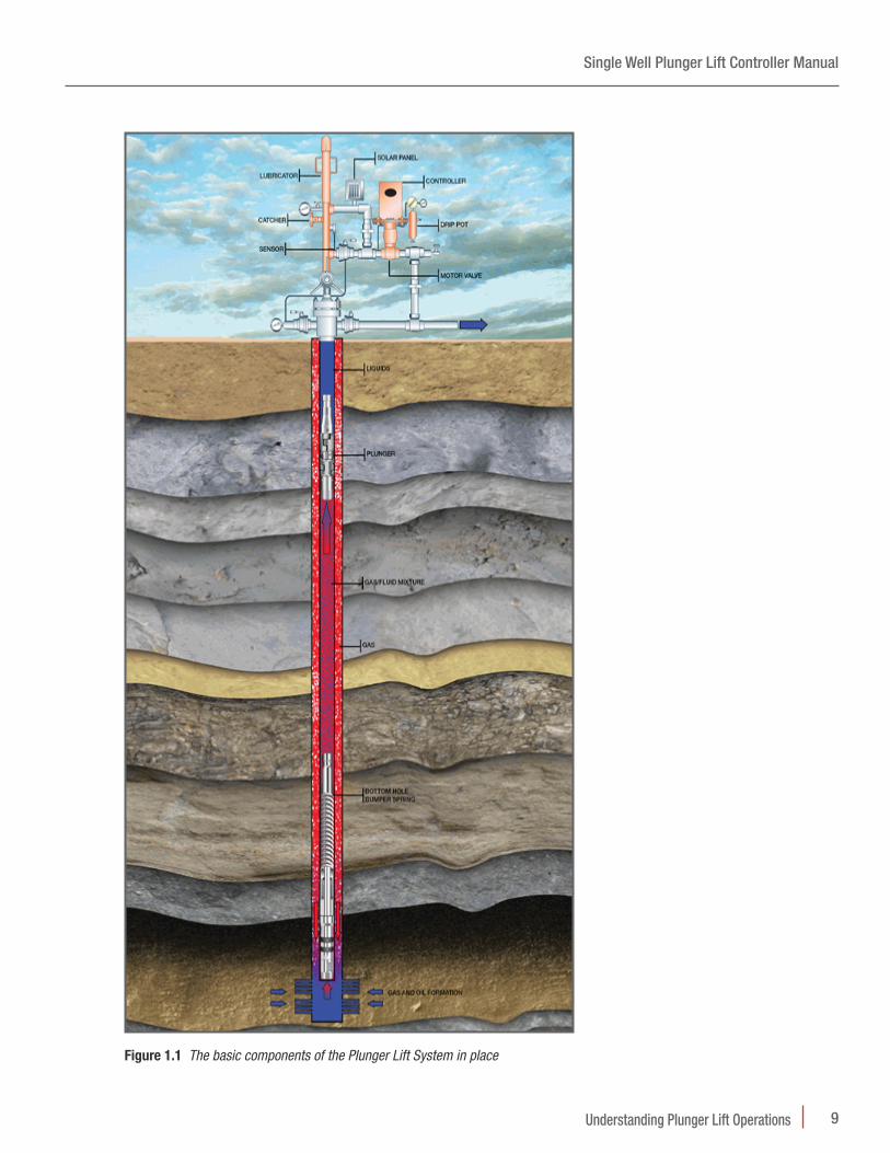
1.1 ComponentsThe well system components of plunger lift operations are:
Plunger Components• Plunger that acts as a well-bore swab
• Lubricator that catches the plunger when it surfaces and provides access for maintenance
• Arrival sensor that indicates when the plunger has surfaced
• Bottom hole bumper spring that cushions the plunger’s fall
Plunger Cycle Control• Motor valve, a pneumatic valve, that controls gas flow
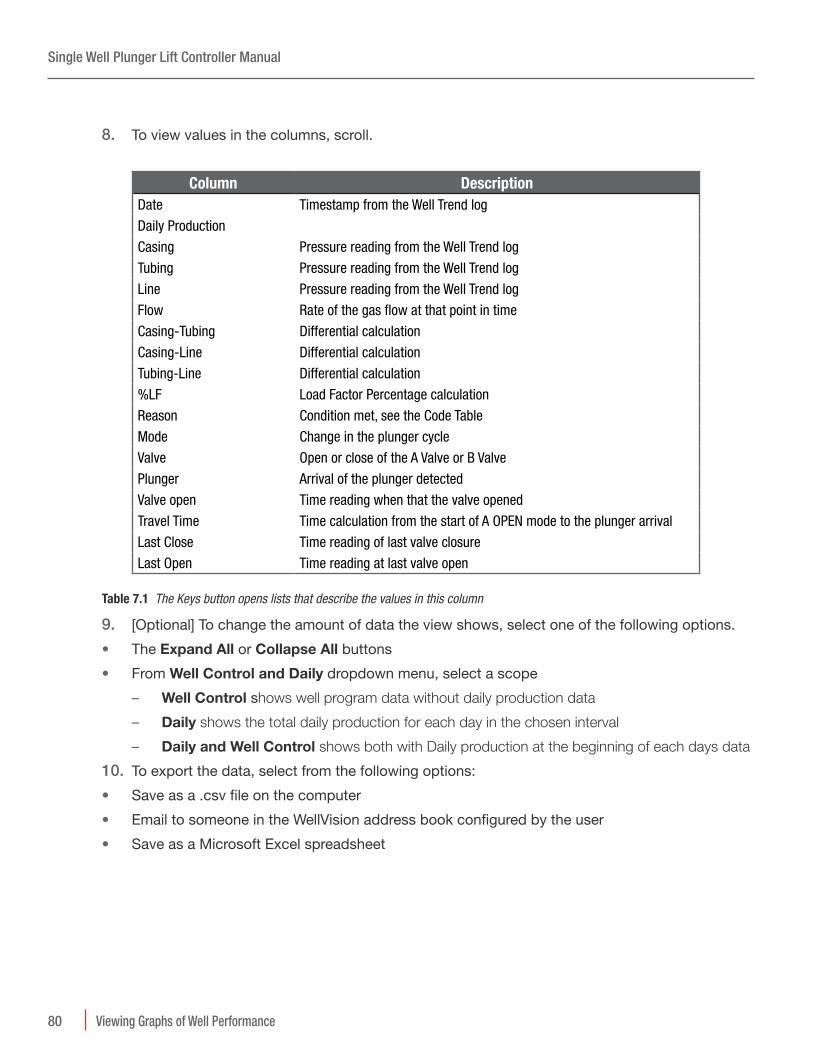
• Production valve , a solenoid valve, that controls the motor valve
• Controller that uses a Well Program to control the production valve
• User interface such as the WellVision™ application, the WellTrekker™ application, or the Walk Up Display to direct the controller
– Analog and digital devices that provide data inputs the controller monitors
– Sales line pressure sensor
– Tubing pressure sensor
– Casing pressure sensor
– Other devices
• [Optional] Tank valve a solenoid valve for a vent that can relieve backpressure on the Sales Line and assist the plunger cycle
Production on Site (provided by the site owner)• Sales line
• Separator that separates gas, oil, and water
• Tank that stores the liquids removed by the plunger
Single Well Plunger Lift Controller Manual
9Understanding Plunger Lift Operations
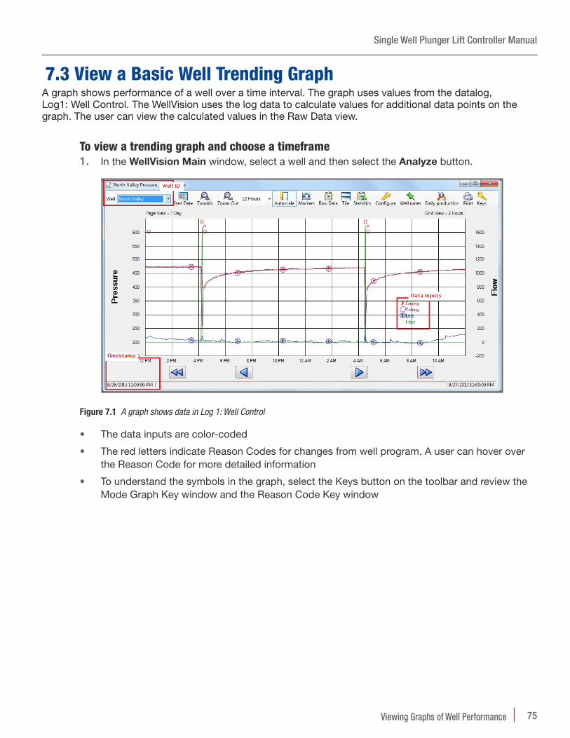
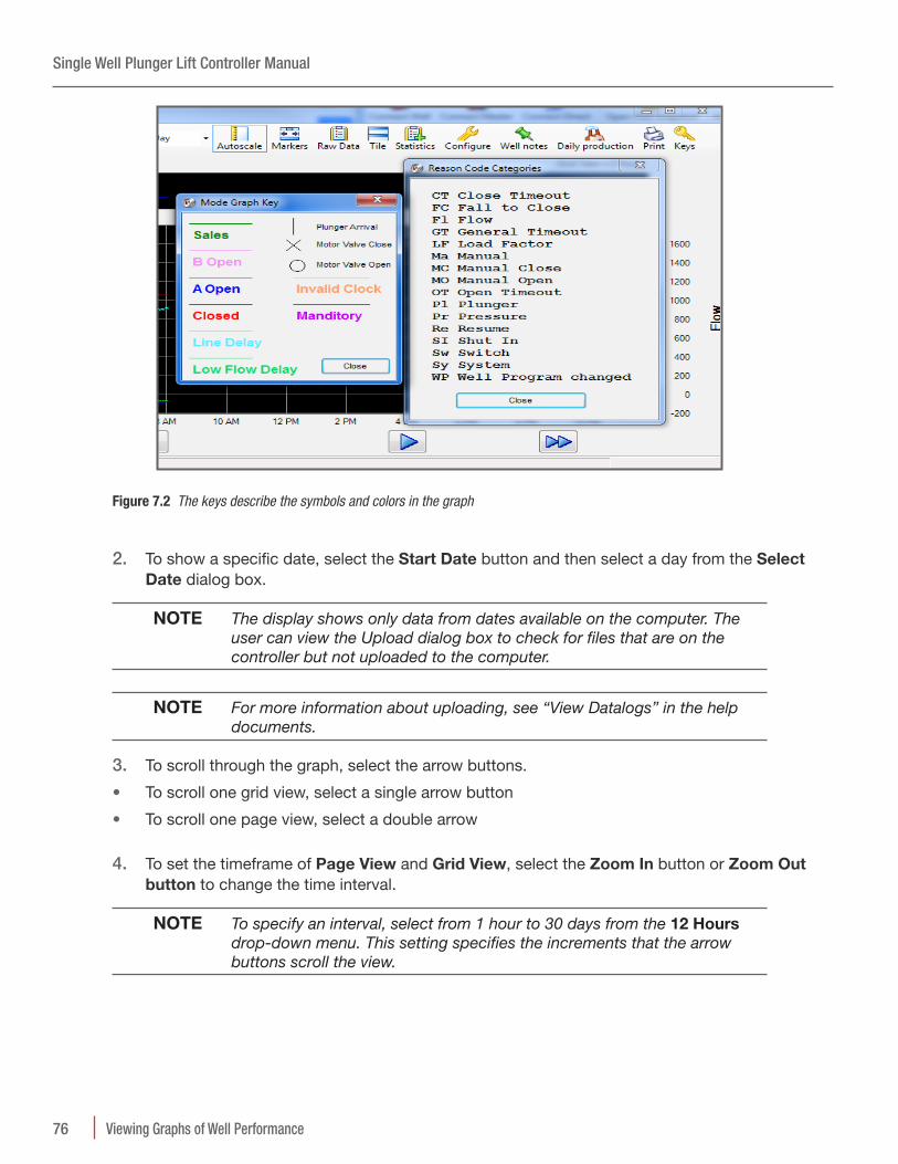
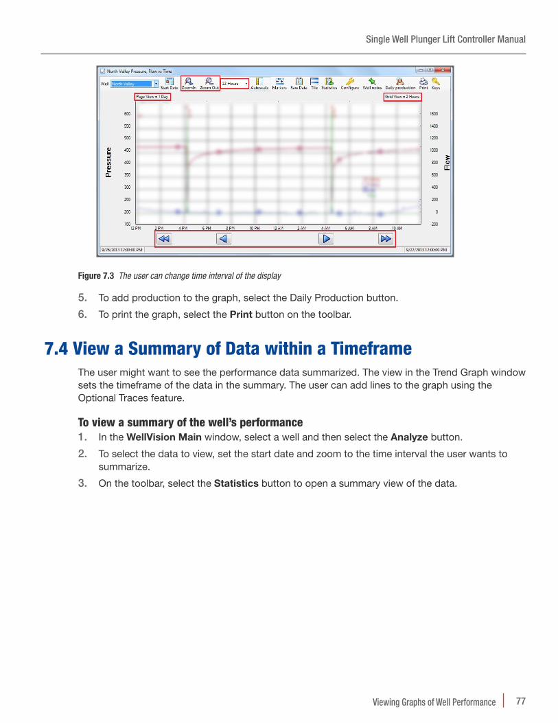
Figure 1.1 The basic components of the Plunger Lift System in place
Single Well Plunger Lift Controller Manual
10 Understanding Plunger Lift Operations
1.2 Plunger Lift CycleThe plunger system lifts the liquids using pressure from the gas flow. The plunger moves between the bottom hole bumper spring and the lubricator at the top of the well. The Motor Valve controls physical flow of the gas. The production valve controls when the Motor Valve is open and closed. When the production valve is closed, the gas flow is off. The plunger falls down the well, through the liquid, and to the bottom hole bumper spring. When the production valve is open, the gas flow is on. The natural pressure from the gas flow lifts the plunger. The liquids move ahead of the plunger, out of the well, and into a separator or directly into the tanks. The separator directs gas into the Sales line, oil to an oil tank, and water to a water tank.
The controller uses a Well Program to direct the components through the plunger cycle. The plunger cycle has modes. The Well Program specifies the modes used during the cycle. Using the Well Program, the controller optimizes production in response to the well conditions. The Well Program has production methods to simplify configuration of optimization. The user chooses a production method and enters set points to create a Well Program.
The following paragraphs describe the modes and production methods that the Well Program uses to optimize production.
1 .2 .1 Basic Modes of the Plunger Cycle
The plunger cycle has basic modes: FALL, CLOSE, A OPEN, and SALES. During FALL mode, the plunger returns to the bottom of the well. During CLOSE mode, the pressures build in the well. The well is not producing gas. During A OPEN mode, the plunger rises to the top with the liquids. After the plunger arrives, the Well Program uses SALES mode to produce gas.
The modes that the Well Program uses depend on the arrival of the plunger, on the production method, and set points. An arrival sensor detects the surfacing of the plunger. The controller monitors this sensor and other input devices. The controller compares the data inputs with the set points specified by the user in the Well Program. In the basic scenario for the Time method, after the plunger arrives, the controller directs the Well Program into SALES mode.
Each mode has primary set points and a group of secondary set points. The basic set points are periods of time or pressure values. Additional set points are values used in a calculation. The production method determines which set points the Well Program uses to exit and enter modes. For a basic example, the primary set points for the Time Method are Fall Time, Close Time, A Open Time, and Sales Time.
1 .2 .2 Conditional Modes of the Plunger Cycle
The controller and Well Program can respond automatically to well conditions. The well conditions affect the arrival of the plunger. A Well Program has a group of secondary set points that specify conditional modes: Line Delay, Mandatory Shut-In, B Open, and B Delay. These set points allow the plunger lift system to respond to the conditions of the well. The production method specifies which set points the controller uses to respond to well conditions.
To optimize production in response to well conditions, the Well Program has modes for using delay, shut-in, and the Tank Valve. Not all well systems have a Tank Valve, but a Well Program can use it to optimize production.
For an example of a delay, the basic mode, A OPEN, is a fixed time, A Open Time. However, well conditions can slow the arrival of the plunger. If the Well Program specifies the set point, Delay Close, the controller can allow production beyond the time set for A OPEN mode. The plunger does not arrive but gas continues to flow and the plunger continues to rise.
To close production in response to conditions, the system has a MANDATORY SHUT-IN mode.
Single Well Plunger Lift Controller Manual
11Understanding Plunger Lift Operations
The primary set point for this mode is a time setting. However, the controller can use a pressure setting on the Casing to enter this mode. For example, if the plunger does not arrive during the time specified for the set point, A Open, the controller counts down the time interval specified by the set point and detects that the pressure on the casing is lower. After that time, the Well Program enters Mandatory Shut-in mode and production stops so that pressure can build to raise the plunger on the next plunger cycle.
1.3 Optimization Programs, Production Methods, and Set Points
The user can specify a Well Program in the WellVision application. Using the information unique to the well, the user chooses a production method and specifies the set points. The controller uses this Well Program to evaluate the data inputs and direct operations.
The Well Program can include the following factors to adjust production. These factors apply to every production method.
Constant factors• Tubing depth
• Tubing diameter
• Plunger type or style
Variable factors• Sales line pressure
• Production ratio of gas-to-liquid
Some set points are common to all of the methods. These set points close the well to protect the gas lines from damage or can respond to possible damage.
For example, to monitor backpressure and protect the sales line, each method includes the following set points for that line:
• High Line Shut-in Pressure: The maximum pressure that the program allows on the line before automatically closing. To prevent shut-in due to momentary spikes in pressure, the user can specify a delay time.
• High Line Pressure Shut-in Delay time: A period of time the controller samples the pressure. The controller uses the samples to decide if a high reading is temporary or steady. If temporary, production can continue. If steady, the program closes the well.
• Low Line Shut-in Pressure: The minimum pressure the program allows on the line before automatically closing the well.
NOTE Best Practice Always enter values for these set points to protect the Sales Line. These settings can prevent ruptures or close the well in the case of a rupture. Also, set the Notifications tool to send a text or an email in response to alarms. For more information about the Notifications tool.
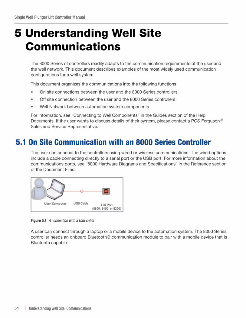
Single Well Plunger Lift Controller Manual
12 Understanding Plunger Lift Operations
The user can choose from several production methods. Each method employs specific primary set points and a group of associated set points. These set points allow the user to customize movement between the modes in response to well conditions.
The user can disable any set point by entering zero or a value too high to occur. (Zero time is 00:00:00: zero pressure is 0: high time is 99:59:59: and high pressure depends on the gauge).
The WellVision and WellTrekker applications offer the following production methods to optimize a well with the Plunger Lift System:
• Time method
• AutoCycle™
• Casing pressure minus Tubing pressure
• Casing pressure minus Line pressure
• Tubing pressure minus Line pressure
The following paragraphs describe the methods and their set points.
1.4 Time MethodUsing the Time method, the controller manages the well using set points of time. The times for FALL, A OPEN, CLOSE, and SALES modes repeat for every plunger cycle. The Well Program offers additional set points to respond to well conditions. The following sections describe how the controller and the Well Program work together through the basic and conditional modes of the plunger cycle.
1 .4 .1 Time Set Points and the Basic Plunger Cycle
A basic Well Program, that uses the time method, moves through the following modes using plunger arrival and time countdowns.
The controller closes the production valve and the Well Program enters the FALL mode. During FALL mode, the plunger drops. The controller counts down the time specified for Fall Time. The Well Program enters CLOSE mode. The controller counts down the time specified for Close Time. During the CLOSE mode, pressure builds in the well. The Controller monitors the data coming from the pressure sensors. However, the Well Program using a Time method does not use pressure readings to change modes. The controller continues to monitor pressures and the Well Program can use pressure settings to override the time settings.
After the Close Time expires, the Well Program enters A OPEN mode and opens the production valve. The controller counts down the time set in A Open Time. This setting should match the time the plunger usually takes to come up the wellbore and remove the liquids. The arrival sensor detects the surfacing of the plunger. The controller directs the Well Program to enter SALES mode. The controller counts down the time set in Sales Time. After the Sales Time expires, the controller directs the Well Program to enter FALL mode and closes the production valve. The process repeats. If the Sales Time is zero (00:00:00), the Well Program enters FALL mode. The user can turn off any set point for time with a value of zero (00:00:00).
1 .4 .2 Pressure Set Points and the Time Method
If the user specifies the set points for high and low line pressure, the Well Program responds to the pressure settings by entering DELAY CLOSE mode. The sequence of the modes depends on when
Single Well Plunger Lift Controller Manual
13Understanding Plunger Lift Operations
the controller detected the High Line Shut-In pressure and the results of the sampling during the time set in High Line Pressure Shut-in Delay.
If the pressure sampling reveals the pressure temporarily spiked and then fell, the Well Program returns to the previous mode. The controller continues to count down the time set for that mode during the delay. The delay does not change the duration of A OPEN mode or SALES mode. If the sampling reveals a possible problem, the Well Program closes the well and enters FALL mode. Well conditions change and the changes affect the plunger arrival. To respond to variations in the plunger’s arrival, the user can specify additional set points in the Well Program.
1 .4 .3 Other Conditional Modes and Set Points
The plunger might not surface as expected during A OPEN mode. The flow might be too low to raise the plunger or excessive backpressure might be the issue. To raise the plunger, the program must close the production valve for a time to build pressure or the system must relieve excessive backpressure through a Tank valve.
Respond to no plunger by closing Production ValveTo close the production valve, the Well Program offers a set point, Mandatory Shut-in Time. After the A Open time expires, the controller checks for data from the arrival sensor. If the controller cannot verify arrival and the program provides a Mandatory Shut-In time, the controller directs the program into MANDATORY mode and counts down the time. After the time expires, the Well Program enters FALL mode.
Respond to no plunger by opening Tank ValveIf the system has a Tank valve, the controller can direct the valve to open and vent the backpressure. With the backpressure relieved, the flow might raise the plunger and the sensor can detect the arrival.
NOTE To add this response to the program, the user specifies a B Open Time. After the plunger arrives and the time expires, the Well Program enters B DELAY mode. The program uses the B Delay Time before entering SALES mode. The controller counts down the Sales Time. The program enters FALL mode. The cycle repeats.
If the flow cannot raise the plunger with the backpressure released, then the program enters MANDATORY SHUT-IN mode. The controller counts down the Mandatory Shut-In time. When the controller detects the required pressure, the program enters OPEN mode. The cycle repeats.
1.5 Pressure MethodsA well analysis might indicate that pressures instead of time would optimize production more effectively. The user can choose a production method that uses pressure differentials. The WellVision and WellTrekker applications offer the following calculations as methods.
• Casing pressure minus Tubing pressure
• Casing pressure minus Line pressure
• Tubing pressure minus Line pressure
Single Well Plunger Lift Controller Manual
14 Understanding Plunger Lift Operations
For each of these methods, the user specifies a differential in pressure based on the well’s conditions. The primary set point is Differential Open Pressure. The set point answers the question: “At what pressure difference, does the user want the Well Program to enter A OPEN mode?” Time still plays a role as the controller counts down Fall Time before evaluating the pressure differential. After the Fall Time expires, the controller evaluates the pressures. If the difference meets pressure criteria specified by the set points shown as a delta p (∆p), then the Well Program enters A OPEN mode.
Basis for differential Well opens if: Well exampleCasing pressure – Line pressure
Difference in pressure is greater than (>) the setting
Most well configurations
Tubing pressure – Line pressure
Difference in pressure is greater than (>) the setting
Well with a packer and no annular pressure
Casing Pressure – Tubing pressure
Difference in pressure is less than (<) the setting
Well with slow building casing pressures
Table 1.1 Production Methods and Pressure Differential
NOTE For more information about the pressure methods, see “Configuring a Single Well” section.
1.6 Automatic Adjustment for Plunger ArrivalThe AutoCycle program provides automatic adjustments using the plunger arrival and number of arrivals. Using the AutoCycle program, a Well Program uses initial settings, monitors the arrival of the plunger, and adjusts time or pressure settings. These adjustments fine-tune the production cycle for optimum plunger speed, liquid removal, and well performance.
For this method, the controller monitors and records data about the arrival of the plunger. The Well Program uses the AutoCycle program to respond with adjustments immediately.
1 .6 .1 AutoCycle Program
The AutoCycle program uses the plunger speed to optimize production. The user provides values for a set of arrival times. These values depend on the specific well. The arrival times indicate to the AutoCycle program the speed of the plunger. Given the depth of the well and the arrival time, the AutoCycle program calculates the speed by dividing the depth by the arrival time.
Maintaining an appropriate speed is critical to the production and safety of the well. Plungers that arrive too fast can damage wellhead components at the surface. This damage might lead to failure. Plungers that arrive too slowly might indicate that pressures are falling. The pressure might be too low to raise the plunger. To optimize production, the AutoCycle program uses a set of arrival windows. Each window type has a set of counters and a set of adjustments.
Single Well Plunger Lift Controller Manual
15Understanding Plunger Lift Operations
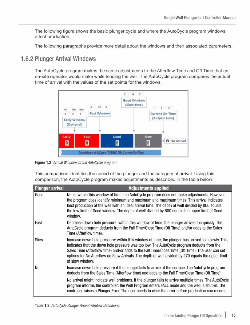
The following figure shows the basic plunger cycle and where the AutoCycle program windows affect production.
The following paragraphs provide more detail about the windows and their associated parameters.
1 .6 .2 Plunger Arrival Windows
The AutoCycle program makes the same adjustments to the Afterflow Time and Off Time that an on-site operator would make while tending the well. The AutoCycle program compares the actual time of arrival with the values of the set points for the windows.
Figure 1.2 Arrival Windows of the AutoCycle program
This comparison identifies the speed of the plunger and the category of arrival. Using this comparison, the AutoCycle program makes adjustments as described in the table below:
Plunger arrival Adjustments appliedGood None, within this window of time, the AutoCycle program does not make adjustments. However,
the program does identify minimum and maximum and maximum times. This arrival indicates best production of the well with an ideal arrival time. The depth of well divided by 800 equals the low limit of Good window. The depth of well divided by 600 equals the upper limit of Good window.
Fast Decrease down hole pressure: within this window of time, the plunger arrives too quickly. The AutoCycle program deducts from the Fall Time/Close Time (Off Time) and/or adds to the Sales Time (Afterflow time).
Slow Increase down hole pressure: within this window of time, the plunger has arrived too slowly. This indicates that the down hole pressure was too low. The AutoCycle program deducts from the Sales Time (Afterflow time) and/or adds to the Fall Time/Close Time (Off Time). The user can set options for No Afterflow on Slow Arrivals. The depth of well divided by 270 equals the upper limit of slow window.
No Increase down hole pressure if the plunger fails to arrive at the surface. The AutoCycle program deducts from the Sales Time (Afterflow time) and adds to the Fall Time/Close Time (Off Time).
No arrival might indicate well problems. If the plunger fails to arrive multiple times, The AutoCycle program informs the controller: the Well Program enters FALL mode and the well is shut-in. The controller raises a Plunger Error. The user needs to clear the error before production can resume.
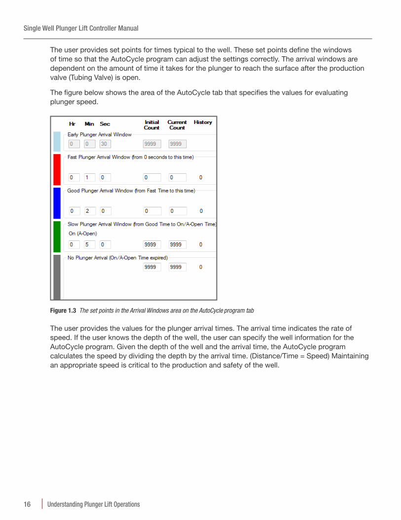
The user provides set points for times typical to the well. These set points define the windows of time so that the AutoCycle program can adjust the settings correctly. The arrival windows are dependent on the amount of time it takes for the plunger to reach the surface after the production valve (Tubing Valve) is open.
The figure below shows the area of the AutoCycle tab that specifies the values for evaluating plunger speed.
Figure 1.3 The set points in the Arrival Windows area on the AutoCycle program tab
The user provides the values for the plunger arrival times. The arrival time indicates the rate of speed. If the user knows the depth of the well, the user can specify the well information for the AutoCycle program. Given the depth of the well and the arrival time, the AutoCycle program calculates the speed by dividing the depth by the arrival time. (Distance/Time = Speed) Maintaining an appropriate speed is critical to the production and safety of the well.
Single Well Plunger Lift Controller Manual
17Understanding Plunger Lift Operations
The figure below shows the AutoCycle tab. The user can accept default values that are based on a depth of 8000 feet. The program can meet any level of control the user might want to apply. The user can supply an initial set of times specific to the well and allow the AutoCycle program to adjust automatically. Or the user can enter adjustments.
Figure 1.4 The AutoCycle Tab
To tailor the program to the well, the program has counters the user can change to match the characteristics of the well. The following section describes the counters and the section after that describes the adjustments.
1 .6 .3 Plunger Arrival Counts
The user can adjust the AutoCycle program by providing arrival counts that are associated with each window. Each window has an initial and a current counter.
• The Initial specifies the number of arrivals to match before the program responds. This count remains at the default value until the user changes it. The program does not adjust this number.
• The Current counter displays the number of remaining arrivals required to trigger a mode change. This counter reduces the value by one for each arrival in the window. When this counter equals zero (0), the program changes to the mode appropriate for the type of arrival.
The counts that close the well require the arrivals to be consecutive such as Early, Slow, or No Plunger. Requiring consecutive arrivals keeps the well open despite occasional plunger errors but triggers a shut-in for a pattern of errors. The counts that move the well program from A OPEN to SALES (AFTERFLOW) are nonconsecutive such as Fast and Good. The nonconsecutive counts allow the well to produce for Fast or Good arrivals without interruption.
Single Well Plunger Lift Controller Manual
18 Understanding Plunger Lift Operations
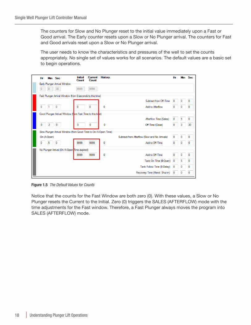
The counters for Slow and No Plunger reset to the initial value immediately upon a Fast or Good arrival. The Early counter resets upon a Slow or No Plunger arrival. The counters for Fast and Good arrivals reset upon a Slow or No Plunger arrival.
The user needs to know the characteristics and pressures of the well to set the counts appropriately. No single set of values works for all scenarios. The default values are a basic set to begin operations.
Figure 1.5 The Default Values for Counts
Notice that the counts for the Fast Window are both zero (0). With these values, a Slow or No Plunger resets the Current to the Initial. Zero (0) triggers the SALES (AFTERFLOW) mode with the time adjustments for the Fast window. Therefore, a Fast Plunger always moves the program into SALES (AFTERFLOW) mode.
Single Well Plunger Lift Controller Manual
19Understanding Plunger Lift Operations
The same is true for the Good window default values. Notice that good arrivals have associated set points and not adjustments.
• Current Afterflow (Sales Time)
• Current Off-Time (Close Time)
• Min Off-Time (Fall Time)
• Max and Min limits on Afterflow
Notice that the counts for the Slow window are equal at five (5). After five (5) consecutive Slow arrivals, the Current count is zero (0) and the program enters CLOSE mode. The program applies the time adjustments to influence the next cycle toward a Good arrival.
As long as the arrivals are in the Slow window, the program adds to the Off-Time (Close Time) and deducts from the Afterflow time (Sales Time) of the next cycle. The program continues to adjust the times until the plunger arrives in either a Good or Fast window. This change resets the Slow Count from zero (0) to the Initial count of five (5). The program continues to evaluate the arrivals and apply adjustments based on the arrival type and the counts.
The following table summarizes the description of the counts:
For the window…
Current shows # that are… Current Resets to Initial on…
Mode triggered when Current = 0
Early Consecutive Any other arrival type CLOSE
Fast Nonconsecutive Any Slow or No arrival SALES
Good Nonconsecutive Any Slow or No arrival SALES
Slow Consecutive Nonconsecutive and Fast or Good arrival
CLOSE*
No Plunger Consecutive Any Fast or Good arrival CLOSE
* Unless the Enable Afterflow on Slow is selected on the AutoCycle tab
Table 1.3 Plunger Counts and Arrival Windows
Single Well Plunger Lift Controller Manual
20 Understanding Plunger Lift Operations
The following section describes the adjustments for the arrival windows and the set points of the Good Window.
1 .6 .4 Automatic Time Adjustments
The AutoCycle program compares the actual time of arrival with the values of the window set points. This comparison identifies the speed of the plunger and the category of arrival. The program applies the adjustments to the Afterflow (Sales) time or the Off-Time (Close) if the plunger arrival is outside the Good Arrival window and the count for the window is zero (0). The adjustments can increase or decrease pressure to control the plunger speed. The Fast, Slow, and No Plunger windows have adjustment set points the user can specify.
• Afterflow (Sales) Afterflow (Sales) relieves pressure after the plunger arrives. Shorter Afterflow (Sales) relieves less pressure for the next Tubing On (Open) mode while longer Afterflow cycles relieve more pressure. Less pressure slows speed and increases time it takes for the plunger to arrive.
• Current Nff-Oime Adjustments Tubing Off cycles allow pressure to build in order to lift the plunger and liquids to the surface. Longer Tubing Off (Close) modes result in more pressure buildup: shorter Tubing Off (Close) modes result in less pressure buildup. More pressure increase speed of the plunger and decreases the time it takes for the plunger to arrive.
Figure 1.6 Section of the AutoCycle tab for reading or specifying adjustments
Smaller Time AdjustmentsThe user can set the AutoCycle program to make proportional adjustments. Proportional adjustments are partial adjustments based on how far the plunger arrival is from the Good Arrival time.
Single Well Plunger Lift Controller Manual
21Understanding Plunger Lift Operations
NOTE Best Practice If the arrival time is very close to the Good Arrival window use the option for proportional adjustment.
1 .6 .5 AutoCycle Pressure Set Points
The user can set the program to respond to pressure readings by using the Pressure Overrides feature. The user can specify pressure set points or differentials that move the program from A OPEN mode to AFTERFLOW (SALES) mode or to CLOSE mode.
The adjustments for the Casing Pressure, Tubing Pressure, and Differential Pressure Overrides on Fast, Slow, and No Arrivals are available.
The user can specify pressure set points that change the mode of the AutoCycle program under certain conditions. The following lists summarize the pressure conditions that trigger the production value (Tubing Valve) to open or close.
Open Production Valve (Tubing Valve) Overrides• If Casing pressure is greater than or equal to the set point
– Casing Pressure >=
• If Tubing pressure is greater than or equal to the set point
– Tubing Pressure >=
– If the differential of Tubing pressure and Line pressure is greater than or equal to the set point
Close Production Valve (Tubing Valve) Overrides• If Casing pressure is less than or equal to the set point
– Casing Pressure <=
• If Tubing pressure is less than or equal to the set point
– Tubing Pressure <=
• If Line pressure is greater than or equal to the set point
– Line Pressure >=
– A delay time is optional
– Shuts in the well until the condition is no longer met
– High Line Delay Clear <Casing - Tubing <= (during afterflow)
– Flow Rate <= (during afterflow)
Safety Shut-Down – Casing Pressure >=
– Tubing Pressure >=
– Tubing Pressure >=
Single Well Plunger Lift Controller Manual
22 Understanding Plunger Lift Operations
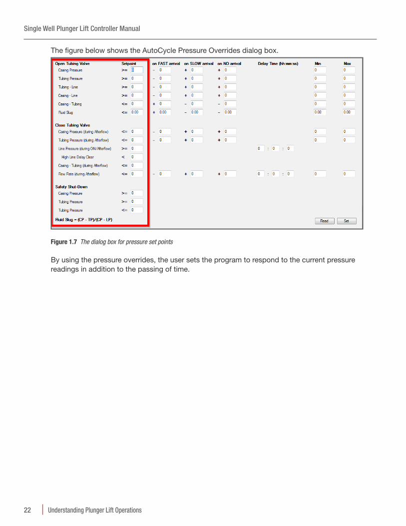
The figure below shows the AutoCycle Pressure Overrides dialog box.
Figure 1.7 The dialog box for pressure set points
By using the pressure overrides, the user sets the program to respond to the current pressure readings in addition to the passing of time.
Single Well Plunger Lift Controller Manual
23Understanding Plunger Lift Operations
1 .6 .6 Automatic Adjustment of Pressure Set Points
The user can set the program to adjust the pressure set points for the next cycle based on the plunger arrival.
Figure 1.8 Adjustments to Pressures for the Arrival Windows
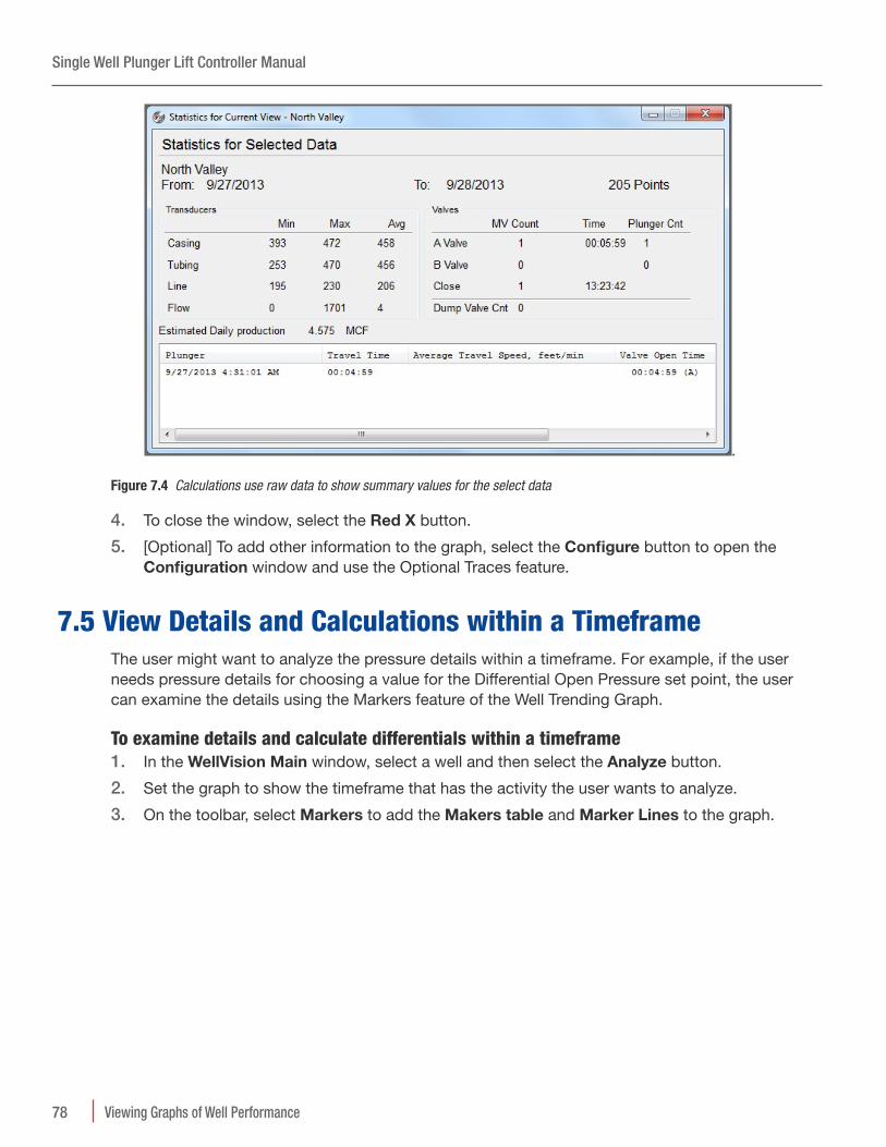
After the user has enabled the program, the user can analyze the results of the optimization program.
NOTE For more information, see “Well Program Set Points for AutoCycle” in the Reference section of the Help Documents.
Single Well Plunger Lift Controller Manual
24 Set Points for Plunger Lift Operations
2 Set Points for Plunger Lift Operations
The user can analyze the well’s performance over time and fine-tune the production method based on trending data. A user examines a current analysis of a well’s performance to set and adjust the frequency of the plunger cycles based on conditions of the well. The rate of liquid accumulation is unique to each well. Changes to the production valve state control the plunger cycle. An electronic controller at the surface automates the state of the production valve.
NOTE For more information about plunger cycles, see “Understanding Plunger Lift Operations” in this manual.
NOTE For information about specifying a Well Program, see “Configuring Single Well Production” in the Guides section of the Help Documents.
This document organizes the set points into control and adjustment categories:
Control Production Modes
Adjustments to Open Pressure Values
Adjustments for Plunger Misses
Control Exit of SALES Mode
Control Shut-in
Control Alarms
The user can specify the following set points to adjust when and how the controller directs the Well Program to respond to well conditions.
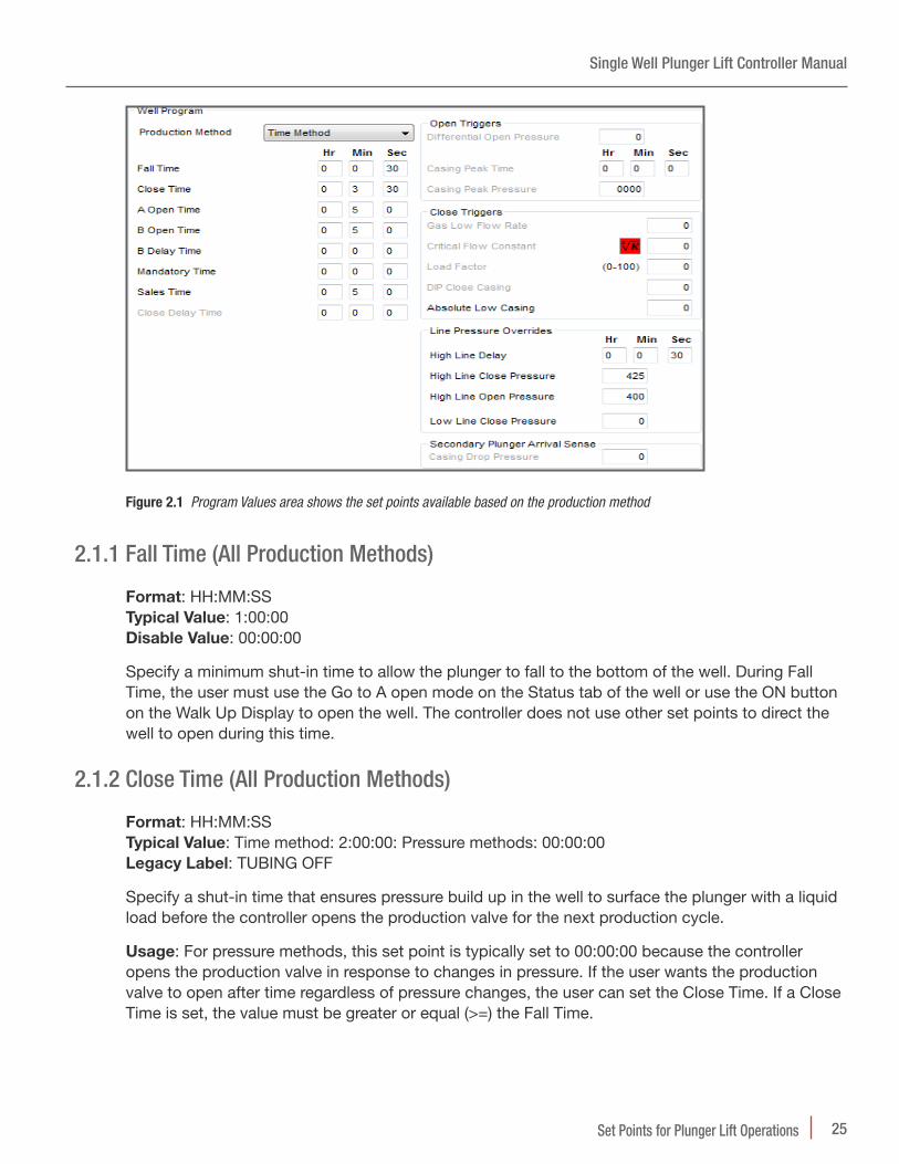
2.1 Control Production ModesThe user chooses the set points depending on the well conditions and the production method. For the Time method, if Well Program’s value for sales time is 00:00:00, the controller closes the production valve when the plunger arrives. For a pressure method, the controller opens the production valve in response to wellhead pressures. On the Well Program tab, the WellVision
application offers only the set points appropriate for the method. The other set points are visible but gray.
Single Well Plunger Lift Controller Manual
25Set Points for Plunger Lift Operations
Figure 2.1 Program Values area shows the set points available based on the production method
Specify a minimum shut-in time to allow the plunger to fall to the bottom of the well. During Fall Time, the user must use the Go to A open mode on the Status tab of the well or use the ON button on the Walk Up Display to open the well. The controller does not use other set points to direct the well to open during this time.
2 .1 .2 Close Time (All Production Methods)
Format: HH:MM:SS Oypical Value: Time method: 2:00:00: Pressure methods: 00:00:00 Legacy Label: TUBING OFF
Specify a shut-in time that ensures pressure build up in the well to surface the plunger with a liquid load before the controller opens the production valve for the next production cycle.
Usage: For pressure methods, this set point is typically set to 00:00:00 because the controller opens the production valve in response to changes in pressure. If the user wants the production valve to open after time regardless of pressure changes, the user can set the Close Time. If a Close Time is set, the value must be greater or equal (>=) the Fall Time.
Single Well Plunger Lift Controller Manual
26 Set Points for Plunger Lift Operations
2 .1 .3 A Open Time (All Production Methods)
Format: HH:MM:SS Oypical Value: Time method: 1:00:00 Legacy Label: Open Time, TUBING ON for the Sales valve
Specify the time that the well is open and gas is flowing through the production valve. During Open Time, the plunger starts to surface and the well produces its initial head gas. Allow enough timing for the plunger to surface with the liquid load. A zero time setting (00:00:00) leaves the well open indefinitely or until a plunger arrival triggers Sales Mode.
2 .1 .4 Sales Time (All Production Methods)
Format: HH:MM:SS Disable Value: 00:00:00 to close the A Valve on plunger arrival Legacy Label: DELAY TIME, Afterflow Time
Specify additional time the controller allows gas flow after the plunger arrival. The countdown starts after the plunger sensor detects the plunger at the wellhead surface.
Usage: Typically, the user sets this value as a backup to close the well if the well conditions do not meet other set points within an appropriate time.
For example, the well’s production might be highest when based on meeting a certain pressure, rate, or other value. Typical set points might be one of the following:
• D.I.P Close Pressure
• Low Gas Flow Rate
• Critical Flow K Factor
NOTE Set the Sales Time higher than the normal time the well is able to sell gas.
2 .1 .5 Delay Close Time (Pressure methods)
Format: HH:MM:SS Disable Value: Use 00:00:00
Specify the time to wait and evaluate whether an increase in the casing pressure is a brief spike or an actual, sustained increase. This set point is evaluated and effective during SALES MODE only. The user can set this to work with Low Gas Flow Rate also.
NOTE For more information about this set point and the modes, see “Pressure Set Points and the Oime Method” in the “Understanding Plunger Lift Operations” document of the Concepts section.
Single Well Plunger Lift Controller Manual
27Set Points for Plunger Lift Operations
NOTE If the D.I.P. Close Pressure is set to 1, 2, or 3 psi, set Delay Close Time to 10, 20, or 30 seconds. Under most conditions, this set point provides time for gas to clear remaining liquids out of the line into the separator. This practice can prevent water from freezing and damaging the line in cold temperatures.
2 .1 .6 Mandatory Shut-In Time (All Production Methods)
Format: HH:MM:SS Oypical Value: Double the typical Close Time Disable Value: 00:00:00 Legacy Label: Recovery Time
Specify the time to countdown when a plunger does not surface.
Usage: If the production valve and tank valve are open and the plunger does not surface, the well probably needs more time to build pressure. The user might set the Mandatory Shut-In Time to double or more than the time required to build enough pressure to surface the plunger.
For example, if a well takes two (2) hours to build enough pressure to surface the plunger, set Mandatory Shut-In Time to at least four (4) hours or more.
NOTE The Mandatory Shut-In Time must be double or more than double the Close Time. If the plunger does not surface, Mandatory Shut-In Time replaces Fall Time. Mandatory Shut-In Time is not in addition to Fall Time.
2 .1 .7 Casing Peak Pressure Time (Pressure methods)
Format: HH:MM:SS Oypical Value: For a well that builds pressure quickly: 00:10:00 – 00:12:00 minutes: for a well that builds pressure slowly: 00:30:00 minutes Disable Value: 00:00:00 Legacy Label: Casing Peak Time
Specify the time that the controller opens the production valve after the casing pressure meets a high value and does not increase in this specified time period. The controller monitors the casing pressure independently of the Differential Open Pressure. The controller counts down the Casing Peak Pressure Time. The counter restarts if the casing pressure increases by 1 psi.
Single Well Plunger Lift Controller Manual
28 Set Points for Plunger Lift Operations
Usage: For example, assume that the value for Casing Peak Pressure Time is 10 minutes. After the production valve closes, the controller counts down the Casing Peak Pressure Time. If the pressure builds 1 psi after 7 minutes and the counter for Fall Time reaches zero, the controller restarts the countdown of Casing Peak Pressure Time. If the casing pressure increases less than (<) 1 psi within 10 minutes, the controller counts down the Casing Peak Pressure Time to zero. The controller checks the current value of the Fall Time countdown. If both the Casing Peak Pressure Time and Fall Time countdowns are at zero, the controller opens the production valve.
NOTE The user can use both Differential Open Pressure and Casing Peak Pressure Time to control the well program. If the user wants to use only the Casing Peak Pressure Time, the user should set the Differential Open Pressure to an extremely high value.
2 .1 .8 High Line Pressure Shut-In Delay (All Production Methods)
Specify a time to wait after detecting a shut-in condition on the line to allow for normal spikes in pressure.
Usage: If the user sets the High Line Pressure, the user can set High Line Pressure Shut-in Delay to keep a brief spike or drop from closing the well. Spikes in pressure often occur when the controller opens the well after an extended shut-in period. After opening the production valve, the controller briefly ignores the sales line pressure during the High Line Pressure Shut-in Delay period. The High Line condition is re-evaluated at the end of the High Line Pressure Shut-In Delay period. If the High Line condition is still valid, the well is shut-in.
For example, the user might set the High Line Pressure Shut-in Delay to six minutes (00:06:00). When the controller opens the well, it starts to count down the Open Time. The pressure might spike for 3 to 5 minutes after opening. For the first six (6) minutes of the A Open Time countdown, the controller keeps the well open even if the High Line Close Pressure is met. If the pressure still meets the shut-in pressure after six (6) minutes, the controller shuts in the well.
2 .1 .9 B Open Time (All Production Methods)
Format: HH:MM:SS Disable Value: 00:00:00 Legacy Label: TANK ON for the Vent valve
Specify the duration to open the vent, if the well system has one.
Usage: This period is after sales of its initial head gas, but before plunger arrival. During B Open Time, the plunger surfaces with its liquid load. Typically, the controller vents gas during B Open Time to the low side of the separator or to a tank.
Single Well Plunger Lift Controller Manual
29Set Points for Plunger Lift Operations
2 .1 .10 B Delay Time (All Production Methods)
NOTE Format: HH.MM.SS Disable Value: 00:00:00 Legacy Label: TANK DELAY for the Vent valve
Specify additional time to keep the tank valve open after a plunger arrival.
Usage: This period is after the arrival of the plunger and before the close of the tank valve. Typically, the user sets B Delay Time to 00:00:00 to close the tank valve immediately when the plunger arrives. A System Engineer can use a delay to allow liquids that follow the plunger to drain out of the dump valve on the Separator.
If the user sets the B Delay Time and the plunger arrives during the B Open Time countdown, the controller delays closing the B valve by starting the B Delay Time countdown. When the countdown reaches zero, the controller closes the B valve and starts the Sales Time countdown by opening the production valve.
2 .1 .11 Differential Open Pressure (Pressure methods)
Format: Pressure value (psi) Disable Value: 0
Specify a difference in pressures that that triggers the controller to open the production valve and the Well Program to enter OPEN mode. The two pressures that determine the Differential Open Pressure depend on the production method the user selects:
• Tubing pressure minus sales line pressure must be greater than the Differential Open Pressure to start well production
• Casing pressure minus tubing pressure must be less than the Differential Open Pressure to start well production
• Casing pressure minus sales line pressure must be greater than the Differential Open Pressure to start well production
Usage: The user considers the typical plunger arrival time to choose an appropriate value for the well. The optimal plunger speed is between 500 and 1000 feet per minute.
• If the plunger is running fast, > 1000 feet per minute, lower the Differential Open Pressure
• If the plunger is running slowly, < 500 feet per minute, increase the Differential Open Pressure
Specify a percentage value for the ratio between two differential pressures. These two differentials are Casing Pressure minus Tubing Pressure to Casing Pressure minus Line Pressure.
Usage: (Not commonly used) Ratio of fluid in the well to energy available to raise the fluid. Must meet the differential and load factor to open.
Single Well Plunger Lift Controller Manual
30 Set Points for Plunger Lift Operations
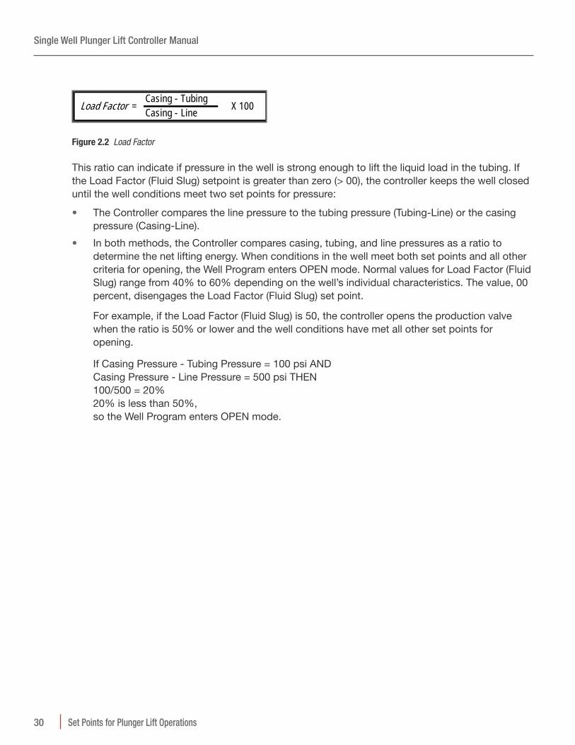
Casing - Tubing
Casing - LineLoad Factor = X 100
Figure 2.2 Load Factor
This ratio can indicate if pressure in the well is strong enough to lift the liquid load in the tubing. If the Load Factor (Fluid Slug) setpoint is greater than zero (> 00), the controller keeps the well closed until the well conditions meet two set points for pressure:
• The Controller compares the line pressure to the tubing pressure (Tubing-Line) or the casing pressure (Casing-Line).
• In both methods, the Controller compares casing, tubing, and line pressures as a ratio to determine the net lifting energy. When conditions in the well meet both set points and all other criteria for opening, the Well Program enters OPEN mode. Normal values for Load Factor (Fluid Slug) range from 40% to 60% depending on the well’s individual characteristics. The value, 00 percent, disengages the Load Factor (Fluid Slug) set point.
For example, if the Load Factor (Fluid Slug) is 50, the controller opens the production valve when the ratio is 50% or lower and the well conditions have met all other set points for opening.
If Casing Pressure - Tubing Pressure = 100 psi AND Casing Pressure - Line Pressure = 500 psi THEN 100/500 = 20% 20% is less than 50%, so the Well Program enters OPEN mode.
Single Well Plunger Lift Controller Manual
31Set Points for Plunger Lift Operations
2 .1 .13 Casing Drop Pressure (Pressure Methods)
Format: Pressure value (psi) Disable Value: 0
Specify the drop in the casing pressure that can initiate the Sales Time countdown without input from the Arrival Sensor.
Usage: Specify this set point as a backup in the following cases:
The Arrival Sensor fails to detect a plunger arrival
The sensor malfunctions
The well does not have a plunger installed
The wellhead configuration affects the plunger travel into the lubricator. The plunger can arrive but the plunger arrival sensor might not detect the plunger every time. Use Casing Drop Pressure as a backup. A drop in pressure on the casing can indicate that the well is unloading and can allow gas flow.
The user can let the well run without a plunger. Casing Drop Pressure allows the well to enter SALES mode without plunger detection.
Apply as a temporary fix for a faulty arrival sensorIf the plunger arrival sensor malfunctions, the user can apply the Casing Drop Pressure as a backup for the sensor temporarily. Setting the Casing Drop Pressure can prevent the tank valve from opening if the well is unloading. This set point can prevent abrasion on the plunger.
The user needs the value for casing pressure at the time that the production valve opens and from the moment the plunger surfaces. The user can get this information from the datalogs. For more information about viewing datalogs, see “Monitoring Well Performance” in the Guides section of the Help Documents.
Single Well Plunger Lift Controller Manual
32 Set Points for Plunger Lift Operations
To use Casing Drop Pressure as a backup arrival sensor1. From the raw data in the data logs, note the Casing pressure the moment the production valve
opens and when the plunger surfaces. The figure below shows the two values: 472 and 405.
Figure 2.3 The datalog shows the pressure values
2. Calculate the difference and add 10-15 psi.
The 10-15 psi provides a buffer that ensures that the plunger surfaces before the casing pressure reaches the set point for Casing Drop Pressure.
For example, Casing pressure A Open reading is 472 psi minus (–) arrival reading of 405 psi = 67 psi. The difference, 67 psi, plus (+) the buffer, 15 psi, equals (=) 82 psi. Without a buffer, the Casing Drop Pressure might indicate a plunger arrival too closely and initiate a change by the controller before the plunger actually surfaces.
3. In the Casing Drop Pressure box, enter the calculated value.
2.2 Control Exit of SALES Mode (Pressure Methods Only)The user can configure the Well Program to use pressure values to exit the SALES mode immediately.
Figure 2.4 Some set points initiate the end of SALES mode
Single Well Plunger Lift Controller Manual
33Set Points for Plunger Lift Operations
2 .2 .1 D .I .P . Close Pressure (Pressure Methods)
Format: Pressure value (psi) Oypical Value: 1, 2, or 3 psi for many wells Disable Value: 0 Legacy Label: Differential Close Pressure
Specify the minimum pressure difference that causes the controller to close the well and the Well Program to exit SALES mode.
Usage: After the plunger surfaces, the casing pressure falls and levels off. The liquids begin to accumulate and the casing pressure starts to increase. The higher the user sets the D.I.P Close Pressure, the longer the well attempts to sell gas.
For example, if the user sets the D.I.P. Close Pressure to 3 psi, the controller stops the sale of gas and closes the well when the Casing Pressure rises to 153 psi. 153-150 = 3.
For example, if the user sets the D.I.P. Close Pressure to 10 psi, the Controller stops the sale of gas and closes the well when the casing pressure rises to 160 psi. 160-150 = 10.
NOTE Best Practice To keep the controller from closing the well too soon, the user can set the Delay Close Time. This delay can account for fluctuations as the casing pressure falls.
Typically, the user might set the minimum D.I.P. Close Pressure to 1 psi. If the user disables the Delay Close Time with the value 00:00:00, the controller immediately closes the well when the casing pressure increases. Because the casing pressure is still falling, the controller might close the well too soon.
2 .2 .2 Gas Low Flow Close Rate (Pressure Methods)Format: numeric Disable Value: 0 Legacy Label: Low Flow Rate
Specify a minimum rate of flow to trigger the controller to close the production valve and the Well Program to exit SALES mode. Gas Low Flow Close Rate works with Delay Close Time to ensure the Flow Rate is actually low and not a brief gas flow fluctuation from the EFM. The well program evaluates this condition only during SALES MODE.
Usage: The user might set this by itself or with the Critical Flow Constant. If the Flow Units on the EFM is set to metric (E3M3), the flow rate unit of measurement is one thousand cubic meters.
For example, if the Gas Low Flow Close Rate is set to 300, the Controller closes the production valve when the flow rate falls below 300 mcf. This function keeps the flow rate from dropping to the point where liquids fall back into the tubing.
Specify a gas constant to compensate for pressure fluctuations on the Sales Line and to prevent liquids from returning into the tubing. The Well Program can use this set point along with the Gas Low Flow Close Rate to prevent low pressure on the Sales Line.
If the user specifies a well program that closes the production valve when the flow rate of the sales line is less than a critical flow rate computed with Turner’s equation, set both the Gas Low Flow Close Rate and the Critical Flow Constant. The constant is K factor that allows for fluctuating pressures on the Sales Line. Using these two set points, the well program keeps the flow rate, in combination with fluctuating sales line pressure, from dropping low enough for liquids to flow back into the tubing.
For example, if the user sets Critical Flow Constant to 65506 and sets Low Flow Rate to 300 mcf, the Controller closes the production valve when the flow rate falls below 300 mcf or the Critical Flow Constant falls below 65506. A Critical Flow calculator is included with WellVision to help the user enter the correct setpoint.
2.3 Control Shut-InThe user can specify pressure values that initiate a shut-in. The user can specify set points that delay the Well Program’s response to these pressures.
Figure 2.5 The user can specify values that immediately shut-in the well
2 .3 .1 Low Line Pressure (All Production Methods)
Format: Pressure value (psi) Disable Value: 0
Specify the lowest value for pressure on the Sales Line that the controller should use to close the production valve and direct the Well Program to enter CLOSE mode or to prevent the well from opening. A very low line pressure can indicate a rupture in the line.
2 .3 .2 High Line Pressure (All Production Methods)
Format: Pressure value (psi) Disable Value: 0
Specify the highest value for pressure on the Sales Line that the controller uses to close the production valve or prevent it from opening. The user can set this value to respond to backpressure that prevents the plunger from surfacing.
Venting If the well system has a tank valve and the Well Program includes settings for B Open Time and B Delay Time, the High Line Close Pressure does not close the tank valve.
Single Well Plunger Lift Controller Manual
35Set Points for the AutoCycle™ Program
3 Set Points for the AutoCycle™ Program
The user can configure the AutoCycle program to analyze the well's performance over time and fine-tune the production method based on the speed of the plunger. The user enters a set of time values that categorizes the arrivals. Using the categories and number of plunger arrivals, the program applies adjustment values to the primary set points that control the plunger's speed.
For more information about plunger cycles, see "Understanding Plunger Lift Operations" in the Concepts section of the Help Documents. For information about specifying a Well Program, see "Configuring a Single Well" or "Configuring Production of Multiple Wells" in the Guides section of the Help Documents.
This document organizes the set points into control and adjustment categories:
• Arrival Window Times and Adjustment Set Points
• Pressure Overrides
The user can specify the following set points to adjust when and how the controller directs the Well Program to respond to well conditions.
3.1 Overview of Arrival Windows
Figure 3.1 Set points the user enters to specify the limits on the arrival windows
• TEarly Window (Optional) Plunger runtime between the start of Tubing ON Time and the value for the Early Window.
Single Well Plunger Lift Controller Manual
36 Set Points for the AutoCycle™ Program
• Fast Window Plunger runtime between the values for Early Window and Fast Window. Without the Early Window enabled, the Fast Window is between the start of Tubing ON Time and the value for Fast Window.
• Good Window Plunger runtime between the values for Fast Window and Good Window. The Good Window value in the user interface is the same as the AutoCycle keypad value for Slow Time or on the Well Program tab, Tubing ON Time. The user might also find it referred to at TUBING ON time in legacy documents.
• Slow Window Plunger Runtime is between the value for Good Window and Current On-Time (A Open Time).
• o Plunger Any time after Tubing ON Time expires.
3 .1 .1 Reset Defaults Button
Resets the set points in the windows to the default values and clears the totals and counts.
3.2 Early Window AreaThe user might want the program to shut in the well for arrivals that are dangerously fast. For these conditions, the AutoCycle program offers an optional Early Window.
3 .2 .1 Enable Early Arrival Option
Adds or disables the Early Arrival Window to the AutoCycle program. Allows the user to configure the program to shut in the well if conditions cause the plunger to travel at dangerous speeds.
3 .2 .2 Hr Min Sec in the Early Window area
Format: HH:MM:SS Oypical Value: 00:00:08 Legacy Keypad Command: 27 Legacy Label: EARLY TIME
Specify the time that sets the limit between the start of Tubing ON time and the Fast Window.
Specify the number of arrivals within the Early Window before the controller closes the well. This value provides a delay to shut in for a single dangerously fast plunger arrival. The user can accept the default of two (2) or specify a new value. The value does not change automatically.
Single Well Plunger Lift Controller Manual
37Set Points for the AutoCycle™ Program
3 .2 .4 Current Count in the Early Window area
Format: ## Oypical Value: 2 Legacy Keypad Command: 29 Legacy Label: CURRENT EARLY
After the initial setting by the user, this counter indicates the number of consecutive arrivals that have occurred within the Early Window. The AutoCycle program reduces this count for each arrival in the Early Window. When this counter reaches zero (0), the controller shuts in the well. The AutoCycle program resets this counter to the initial value if plunger arrives within the Fast or Good windows.
3.3 Fast Window AreaThis area provides the limits and values for adjusting the set points to influence the plunger arrival toward a good arrival.
3 .3 .1 (Fast Plunger Time) (Hr Min Sec)
Format: HH:MM:SS Oypical Value: Tubing depth/800 Legacy Keypad Command: 01 Legacy Label: FAST TIME
Specify the time that sets the limit between Fast Window and Good Window. The user can calculate a good initial value using this equation:
Fast Window = Depth of Tubing / 800TEquation 27 1: Fast Time
Specify the number of arrivals in the Fast Window before the controller starts to adjust Current Off Time and Current Afterflow. Fast Arrivals the plunger must make before allowing Afterflow to commence. The user can accept the default or specify a new value. The value does not change automatically.
Single Well Plunger Lift Controller Manual
38 Set Points for the AutoCycle™ Program
3 .3 .3 Current in the Fast Window area
Format: ## Oypical Value: Equal to the Initial value for the Fast Window Legacy Keypad Command: 16 Legacy Label: CURRENT FAST
After the initial setting by the user, this counter indicates the number of arrivals that have occurred within the Fast Window. The AutoCycle program reduces this count for each arrival in the Fast Window. When this counter reaches zero (0), the controller applies the adjustments specified in the Fast Window area. After this counter reaches zero (0), the controller enters Afterflow (SALES mode). The AutoCycle program resets this counter to the initial value if plunger arrives within the Slow Window or in the No Plunger Window.
3 .3 .4 History (Read Only)
Format: ## Legacy Keypad Command: 52 Legacy Label: ARRIVAL HISTORY
Indicates the number of plunger arrivals within this window since the user selected the Clear Totals button.
Specify the amount of time to deduct from the Current Off-Time if the arrivals are within the Fast Window. If the Current Off-Time reaches the set point for Minimum Off Time, the controller ignores this value. A low value, such as the typical values, allows the controller to make small changes.
Specify the amount of time to add to the Current Afterflow if the arrivals are within the Fast Window. If the Current Afterflow time reaches the set point for Maximum Afterflow, the controller ignores this value. "A low value as specified in the typical values of 1-5 minutes allows the controller to make small changes.
Single Well Plunger Lift Controller Manual
39Set Points for the AutoCycle™ Program
3.4 Good Window AreaThis area provides the limits for the window and the set points that define a good arrival.
Specify the time that sets the limit between Good Window and Slow Window. A plunger arrival time that is greater (>) than the Slow Time is in the Slow Window. An arrival time that is greater (>) than the Current On-Time is in the No Plunger window. The user can calculate a good initial value using this equation:
Specify the number of arrivals in the Good Window before allowing the well to enter SALES mode (AFTERFLOW) This counter is the initial setting for the Good Window. The user can accept the default or specify a new value. The value does not change automatically.
3 .4 .3 Current in the Good Window area
Format: ## Oypical Value: 5 Legacy Keypad Command: 18 Legacy Label: CURRENT GOOD
After the initial setting by the user, this counter indicates the number of plunger arrivals within the Good Window. The AutoCycle program reduces this count for each arrival in the Good Window. When this counter reaches zero (0), the controller enters SALES (Afterflow) mode. The program resets this counter to the initial value for a No Arrival or the plunger arriving in the Slow Window.
Single Well Plunger Lift Controller Manual
40 Set Points for the AutoCycle™ Program
3 .4 .4 (History Read Only)
Format: ## Legacy Keypad Command: 52 Legacy Label: ARRIVAL HISTORY
Indicates the number of plunger arrivals within this window. This value accumulates from the time the user selected the Clear Totals button.
Specify the time period that the well is open after a plunger arrival.
If the user begins by shutting in on plunger arrival, the afterflow might initially be set at zero (0). The user might want to the program to enter Afterflow (SALES mode) immediately. The user needs to set the time and the well enters Afterflow on the first cycle. The first cycle occurs after the initial counts are satisfied. The limits on this value are the Minimum Afterflow Time and Maximum Afterflow Time. In either case, the Afterflow Time can change as plunger cycles progress.
3 .4 .6 Current Off-Time
Format: HH:MM:SS Oypical Value: Legacy Keypad Command: 04 Legacy Label: Total Off
Specify the total amount of time the well is off or shut in. The AutoCycle program adjusts this set point and the set point, Current Afterflow, in response to arrival times. Limits: This value cannot be set or adjusted to a value less than (<) than Minimum Off Time or greater than (>) the Maximum Off Time.
Single Well Plunger Lift Controller Manual
41Set Points for the AutoCycle™ Program
3 .4 .7 Min Off-Time
Format: HH:MM:SS Oypical Value: Tubing Depth / 200 Legacy Keypad Command: 05 Legacy Label: MIN OFF
Specify the lowest value that the program can reduce the Current Off-Time. This value ensures that the plunger has time to reach the bottom of the tubing before the well opens. The user can calculate a good initial value using this equation:
Specify the highest value the Current Afterflow Time can reach. This setting allows for pressure draw down and can aid in gas measurement and fluid entry problems.
Specify the maximum amount of time the well is open and waiting for the plunger to arrive. This value sets the boundary between the Slow Window and No Plunger. The user can calculate a good initial value using this equation:
Specify the number of arrivals within the Slow Window before the controller closes the well and applies adjustments to Current Afterflow and Current Off-Time. This counter is the initial setting for the Slow Window. This number determines how many consecutive Slow Arrivals the plunger makes before the controller shuts in the well. The user can accept the default of five (5) or specify a new value. The value does not change automatically. To disable shut in, set valve to 9999.
After the initial setting by the user, this counter indicates the number of plunger arrivals within the Slow Window. The AutoCycle program reduces this count for each arrival in the Slow Window. When this counter reaches zero (0), the well enters CLOSE (TUBING OFF) mode. The program resets this counter to the initial value if a plunger arrival is within the Fast or Good Windows.To disable shut in, set valve to 9999.
Single Well Plunger Lift Controller Manual
43Set Points for the AutoCycle™ Program
3 .5 .4 (History Read-Only)
Format: ## Legacy Keypad Command: 52 Legacy Label
Indicates the number of plunger arrivals within this window. This value accumulates from the time the user selected the Clear Totals button.
Specify the amount of time to reduce Current Afterflow if arrivals are in the Slow Window or No Plunger and the Count is zero. The controller adjusts the Afterflow Time for every arrival in the slow arrival or No Arrival after the initial count is met. If Current Afterflow reaches the set point for the Minimum Afterflow Time, the controller ignores this value. A medium time value, such as 5-15 minutes, allows the controller to respond and adjust the plunger speed more appropriately.
Specify amount of time to increase Current Afterflow if arrivals are in the Slow Window and the Count is zero (0). If Current Off Time reaches the set point for Maximum off Time, this value is ignored. A medium time, such as default of 15-30 minutes, allows the controller to respond and influence the plunger speed more appropriately.
Specify the number of arrivals that occur after Current Afterflow expires before the well enters CLOSE (TUBING OFF) mode and the controller applies the adjustment to Current Off-Time. This counter is the initial setting for the No Plunger arrival. This set point determines how many consecutive No Arrivals the well makes before the controller enters CLOSE model. The user can accept the default of three (3) or specify a new value. The value does not change automatically.
After the initial setting by the user, this counter indicates the number of times the plunger either did not arrive or arrived after Current On Time expired. The AutoCycle program reduces this count for missed arrival. When this counter reaches zero (0), the well enters CLOSE (TUBING OFF) mode. The program resets this counter to the initial value if a plunger arrival is within the Fast or Good Windows.
3 .6 .3 (History Read-Only)
3 .6 .4 Add to Off-Time in the No Plunger area
Format: HH:MM:SS Oypical Value: 30-60 minutes, 1 hour is the default Legacy Keypad Command: 13 Legacy Label: OFF N/A (+):
Specify the amount of time to increase Current Off Time if arrivals are longer than the set point for Current On Time. The controller adjusts the Current Off Time for every No Arrival. If the Current Off Time reaches the set point for Maximum Off Time, the controller ignores this value. A high value, such as the default of 60 minutes, allows the controller to respond and influence the plunger speed more appropriately.
Specify the highest value that the controller can increase the Off Time using adjustments. A high value, such as the default of 99:59:59 allows the controller to make unlimited adjustments but does set a limit should the well conditions require it.
3.7 Pressure OverridesThe following table summarizes the set points available on the Pressure Overrides dialog box. The user can open this dialog box by selecting the Pressure Overrides button on the AutoCycle tab.
3 .7 .1 Open Tubing Valve (Production Valve) If Area
Label UsageCP >= Open the Tubing Valve if the Casing Pressure is greater than or equal-to the PSIG setting and the
Minimum Off Time has expired.
TP >= Open the Tubing Valve if the Tubing Pressure is greater than or equal to the PSIG setting and the Minimum Off Time has expired.
TP-LP >= Open the Tubing Valve if the Tubing Pressure - Line Pressure is greater than the PSIG setting and the Minimum Off Time has expired.
CP-LP >= Open the Tubing Valve if the Casing Pressure - Line Pressure is greater than the PSIG setting and the Minimum Off Time has expired.
CP-TP <= Open the Tubing Valve if the Casing Pressure - Line Pressure is less than the PSIG setting and the Minimum Off Time has expired.
Fluid Slug <= Open the Tubing Valve if the Fluid Slug setting is less than or equal to the PSIG setting and the Minimum Off Time has expired.
Table 3.1 Open Tubing Valve (Production Valve) If Area
3 .7 .2 Close Tubing Valve (Production Valve) If AreaThis area offers pressure set points that direct the controller to apply Casing Pressure Off Overrides only during Afterflow if on (YES).
Label PurposeCP <= Close the Tubing Valve if the Casing Pressure is less-than or equal-to the PSIG setting.
TP <= Close the Tubing Valve if the Tubing Pressure is less-than or equal-to the PSIG setting.
LP >= Close the Tubing Valve if the Line Pressure is greater-than or equal-to the PSIG setting.
HLDC < Clear High Line Pressure condition when Line Pressure falls below this setting.
CP-TP <= Close the Tubing Valve if the Casing Pressure - Tubing Pressure is less than the PSIG setting and the Minimum On Time has expired.
Flow Rate <= Close the tubing valve if the Flow Rate is less than or equal to the setting in MSCF.
Table 3.2 Close Tubing Valve (Production Valve) If Area
Single Well Plunger Lift Controller Manual
46 Set Points for the AutoCycle™ Program
3 .7 .3 Plunger Open Adjustments
Label PurposeCP (-) for Fast Open if CP >= decrease adjustment for Fast Arrival.
CP (+) for Slow Open if CP >= increase adjustment for Slow Arrival.
CP (+) for None Open if CP >= increase adjustment for No Arrival.
TP (-) for Fast Open if TP >= decrease adjustment for Fast Arrival.
TP (+) for Slow Open if TP >= increase adjustment for Slow Arrival.
TP (+) for None: Open if TP >= increase adjustment for No Arrival.
TP-LP (-) for Fast Open if TP-LP > decrease adjustment for Fast Arrival.
TP-LP (+) for Slow Open if TP-LP > increase adjustment for Slow Arrival.
TP-LP (+) for None Open if TP-LP > increase adjustment for No Arrival.
CP-LP (-) for Fast Open if CP-LP > decrease adjustment for Fast Arrival.
CP-LP (+) for Slow Open if CP-LP > increase adjustment for Slow Arrival.
CP-LP (+) for None Open if CP-LP > increase adjustment for No Arrival.
CP-TP (+) for Fast Open if CP-TP < increase adjustment for Fast Arrival.
CP-TP (-) for Slow Open if CP-TP < decrease adjustment for Slow Arrival.
CP-TP (-) for None Open if CP-TP < decrease adjustment for No Arrival.
Fluid Slug (+) for Fast Open if FSLUG >= increase adjustment for Fast Arrival.
Fluid Slug (-) for Slow Open if FSLUG >= decrease adjustment for Slow Arrival.
Fluid Slug (-) for None Open if FSLUG >= decrease adjustment for No Arrival.
Table 3.3 Plunger Open Adjustments
3 .7 .4 Plunger Close Adjustments Area
Label PurposeCP (-) for Fast Close if CP <= decrease adjustment for Fast Arrival.
CP (+) for Slow Close if CP <= increase adjustment for Slow Arrival.
CP (+) for None Close if CP <= increase adjustment for Slow Arrival.
TP (-) for Fast Close if TP <= decrease adjustment for Fast Arrival.
TP (+) for Slow Close if TP <= increase adjustment for Slow Arrival.
TP (+) for None Close if TP <= increase adjustment for No Arrival.
Flow Rate (-) for Fast Close if Flow Rate <= decrease adjustment for Fast Arrival
Flow Rate (+) for Slow Close if Flow Rate <= increase for Slow Arrival
Flow Rate (+) for None Close if Flow Rate <= increase for No Arrival
Table 3.4 Plunger Close Adjustments Area
Single Well Plunger Lift Controller Manual
47Set Points for the AutoCycle™ Program
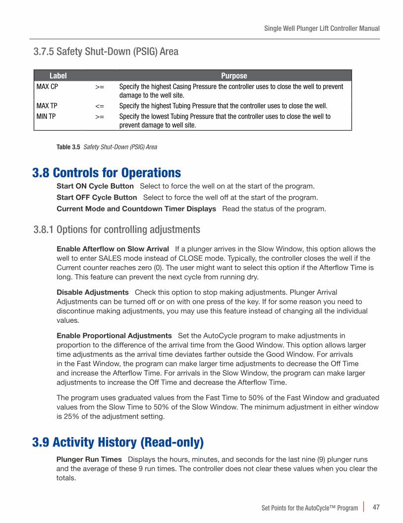
3 .7 .5 Safety Shut-Down (PSIG) Area
Label PurposeMAX CP >= Specify the highest Casing Pressure the controller uses to close the well to prevent
damage to the well site.
MAX TP <= Specify the highest Tubing Pressure that the controller uses to close the well.
MIN TP >= Specify the lowest Tubing Pressure that the controller uses to close the well to prevent damage to well site.
Table 3.5 Safety Shut-Down (PSIG) Area
3.8 Controls for OperationsStart N Cycle Button Select to force the well on at the start of the program.
Start NFF Cycle Button Select to force the well off at the start of the program.
Current Mode and Countdown Oimer Displays Read the status of the program.
3 .8 .1 Options for controlling adjustments
TEnable Afterflow on Slow Arrival If a plunger arrives in the Slow Window, this option allows the well to enter SALES mode instead of CLOSE mode. Typically, the controller closes the well if the Current counter reaches zero (0). The user might want to select this option if the Afterflow Time is long. This feature can prevent the next cycle from running dry.
Disable Adjustments Check this option to stop making adjustments. Plunger Arrival Adjustments can be turned off or on with one press of the key. If for some reason you need to discontinue making adjustments, you may use this feature instead of changing all the individual values.
TEnable Proportional Adjustments Set the AutoCycle program to make adjustments in proportion to the difference of the arrival time from the Good Window. This option allows larger time adjustments as the arrival time deviates farther outside the Good Window. For arrivals in the Fast Window, the program can make larger time adjustments to decrease the Off Time and increase the Afterflow Time. For arrivals in the Slow Window, the program can make larger adjustments to increase the Off Time and decrease the Afterflow Time.
The program uses graduated values from the Fast Time to 50% of the Fast Window and graduated values from the Slow Time to 50% of the Slow Window. The minimum adjustment in either window is 25% of the adjustment setting.
3.9 Activity History (Read-only)Plunger Run Oimes Displays the hours, minutes, and seconds for the last nine (9) plunger runs and the average of these 9 run times. The controller does not clear these values when you clear the totals.
Single Well Plunger Lift Controller Manual
48 8000 Series Walkup Display and Keypad Commands
4 8000 Series Walkup Display and Keypad Commands
The 8000 Series master controllers have a Walk Up display in a case at the site. This display provides the user with a keypad interface to the well automation system. This keypad interface connects directly to the controller. The user can monitor basic well data and configure a basic well program for plunger lift operations. This document describes the functions and commands the user can perform using the keypad.
Figure 4.1 The Walk Up Display is the manual interface to the well controller
4.1 Basic Key SequencesIn general, the user wants to complete one of the following tasks. The keypad has a key for each task.
• View the value of a current setting such as the battery voltage: READ
• Enter a new value such as a set point: SET
• View a report of events such as plunger arrivals: READ
• Enable or disable a feature
Single Well Plunger Lift Controller Manual
498000 Series Walkup Display and Keypad Commands
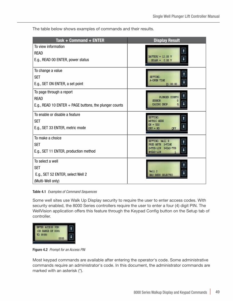
The table below shows examples of commands and their results.
Task + Command + ENTER Display ResultTo view information
READ
E.g., READ 00 ENTER, power status
To change a value
SET
E.g., SET ON ENTER, a set point
To page through a report
READ
E.g., READ 10 ENTER + PAGE buttons, the plunger counts
To enable or disable a feature
SET
E.g., SET 33 ENTER, metric mode
To make a choice
SET
E.g., SET 11 ENTER, production method
To select a well
SET
E.g., SET 52 ENTER, select Well 2
(Multi-Well only)
Table 4.1 Examples of Command Sequences
Some well sites use Walk Up Display security to require the user to enter access codes. With security enabled, the 8000 Series controllers require the user to enter a four (4) digit PIN. The WellVision application offers this feature through the Keypad Config button on the Setup tab of controller.
Figure 4.2 Prompt for an Access PIN
Most keypad commands are available after entering the operator's code. Some administrative commands require an administrator's code. In this document, the administrator commands are marked with an asterisk (*).
Single Well Plunger Lift Controller Manual
50 8000 Series Walkup Display and Keypad Commands
4.2 The Single-Well™ Application Keypad CommandsThe following table is a list of commonly used commands. The user needs to press the Enter key after each command sequence.
8000 Series Single-Well ApplicationCommand +
ENTERTo perform the following Command +
ENTERTo perform the following
ON Turn ON Well/Force A-Open READ/SET 16* Casing Transducer (#1) State, Locality, & Scaling
OFF Turn OFF Well/Force A-Close READ/SET 17* Tubing Transducer (#2) State, Locality, & Scaling
B ON Force B-Open READ/SET 18* Line Transducer (#3) State, Locality, & Scaling
READ Firmware Version READ 19 Read Last A-Open/Close Times
READ/SET ON A-Open Time Interval SET 19 Clear Last A-Open/Close Times
READ/SET OFF Close Time Interval READ/SET 20 Casing Drop Pressure
READ/SET B ON B-Open Time Interval READ/SET 21 Casing Peak Time
READ/SET B 0 A-Open with B READ/SET 22* Modbus Address
READ/SET B 2 B-Delay Time Interval READ/SET 23 Minimum Flow Rate
SET B 9* Reset to Factory Defaults READ/SET 24 Load Factor
READ 00 Battery and Solar Voltages READ/SET 25 Critical Flow K Factor
READ/SET 01 Default Timeouts READ/SET 26 Line Delay Time Interval
READ/SET 02 Sales Time Interval READ/SET 27 Plunger Bottom Depth
READ/SET 03 Mandatory Shut-in Time Interval READ/SET 29 Equalize Mode Status
READ 04 Current Pressures READ/SET 30 Equalize Mode Settings
READ/SET 05 Fall Time Interval READ/SET 31* EFM State and Settings
READ 06 Plunger Travel History READ 32* SD Card File System Status
SET 06 Clear Plunger Travel History SET 32* Prepare SD Card for Removal
READ 07 Current Flow & Accum READ/SET 33* Metric Mode
READ/SET 08 Delay Close Time Interval READ/SET 34* Host Radio Baud Rate
READ/SET 09* Sensor State and Location READ/SET 35 Plunger Hold and Status
READ 10 Totals-Counts, Time, Flows, History
READ 39 Alarm Status
SET 10 Clear Totals READ 40 Well Name
READ/SET 11 Production Method READ/SET 60* A Valve State & Locality
READ/SET 12 Differential A-Open Pressure READ/SET 61* B Valve State & Locality
READ/SET 13 Differential A-Close Pressure (DIP)
READ/SET 62* C Valve State & Locality
READ/SET 14 High Line Close Pressure READ/SET 89 Fast Plunger Time, Count, Too Fast Time
READ/SET 15 Low Line Close Pressure
* Indicates commands that require an administrator PIN if the keypad is using the Walk Up Display security feature
Table 4.2 Commonly Used Commands for the Single-Well Application
Single Well Plunger Lift Controller Manual
518000 Series Walkup Display and Keypad Commands
4.3 The AutoCycle™ Program Keypad Commands (Single-Well only)
The following table is a list of commands to monitor and configure the AutoCycle program using the keypad on a single-well controller.
To configure the AutoCycle program for wells using the Multi-Well application, the user needs to use the WellVision application or the WellTrekker application.
For most of the ACiC Hot Keys, the user can add 100 to the legacy command. Some hot keys have replacement commands for the same feature or function.
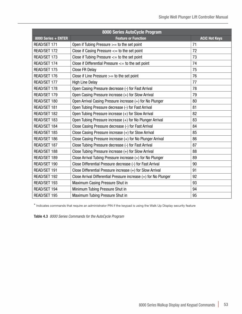
8000 Series AutoCycle Program8000 Series + ENTER Feature or Function ACiC Hot Keys
READ Firmware Version 60
READ/SET B ON Tank On (B Open Time) 31
READ/SET B 2 Tank Delay (B Delay Time) 30
READ 00 System Status (battery/solar voltages) 61
READ 10 Report Pages 1: Plunger Count and Tubing Cycles 2: Valve Counts and Tank Cycles 3-4: Time Totals 5: Accumulations
6-11: Plunger Run Times and History
51-58
SET 10 Clear the Totals 56
READ/SET 26 High Line Shut In Delay 77
READ/SET 100 Auto-Cycle Status: enabled/disabled n/aREAD/SET 101 Fast Time 01
READ/SET 102 Slow Time 02
READ/SET 103 Current On Time (A Open Time, Tubing On Time) 03
READ/SET 104 Current Off Time (Tubing Off Time, Close Time) 04
READ/SET 105 Minimum Off Time (Close Time) 05
READ/SET 106 Afterflow Time (Sales Time) 06
READ/SET 107 Minimum Afterflow Time (Sales Time) 07
READ/SET 108 Maximum Afterflow Time (Sales Time) 08
READ/SET 109 Off Time Decrease (-) for Fast Arrival 09
READ/SET 110 Afterflow Time (Sales Time) Increase (+) for Fast Arrival 10
READ/SET 111 Off Time increase (+) for Slow Arrival 11
READ/SET 112 Afterflow Time (Sales Time) decrease (-) for Slow Arrival 12
READ/SET 113 Off Time increase (+) for No Plunger Arrival 13
READ/SET 114 High Line Delay Clear < Setpoint 14
READ/SET 115 Initial Fast Plunger Arrival Count 15
READ/SET 116 Current Fast Plunger Arrival Count 16
READ/SET 117 Initial Good Plunger Arrival Count 17
READ/SET 118 Current Good Plunger Arrival Count 18
8000 Series AutoCycle Program8000 Series + ENTER Feature or Function ACiC Hot Keys
READ/SET 120 Current Slow Plunger Arrival Count 20
READ/SET 121 Initial No Plunger Arrival Count 21
READ/SET 122 Current No Plunger Arrival Count 22
READ/SET 126 Maximum Off Time 26
READ/SET 127 Early Arrival Time 27
READ/SET 128 Initial Early Plunger Arrival Count 28
READ/SET 129 Current Early Plunger Arrival Count 29
READ/SET 130 Tank Follow Time 30
READ/SET 131 Tank On Time 31
READ/SET 132 Recovery Time 32
READ/SET 138 Open Casing Pressure-Tubing Pressure Increase on Fast Plunger Arrival 38
READ/SET 139 Open Casing Pressure-Tubing Pressure Decrease on Slow Plunger Arrival 39
READ/SET 140 Open Casing Pressure-Tubing Pressure Decrease on No Plunger Arrival 40
READ/SET 141 Open Casing Pressure-Line Pressure Decrease on Fast Plunger Arrival 41
READ/SET 142 Open Casing Pressure-Line Pressure Increase on Slow Plunger Arrival 42
READ/SET 143 Open Casing Pressure-Line Pressure Increase on No Plunger Arrival 43
READ/SET 144 Tubing Pressure-Line Pressure Adjustment for Fast Arrival 44
READ/SET 145 Tubing Pressure-Line Pressure Adjustment for Slow Arrival 45
READ/SET 146 Tubing Pressure-Line Pressure Adjustment for No Arrival 46
READ/SET 147 Fluid Slug Adjustment for Fast Arrival 47
READ/SET 148 Fluid Slug Adjustment for Slow Arrival 48
READ/SET 149 Fluid Slug Adjustment for No Arrival 49
READ 150 Tubing Cycles 50
READ 151 Plunger Counts 51
READ 152 Arrival History 52
READ 153 Plunger Run Times 53
READ 154 Total Tubing ON Time 54
READ 155 Total Tubing OFF Time 55
SET 156 Clear Totals 56
READ 161 System Status 61
READ/SET 162 Control Option Pages: 1: Afterflow on Slow Arrival: enable/disable 2: Plunger Arrival Adjustments: enable/disable 3: Proportional Adjustments: enable/disable 4: Early Plunger Arrival: enable/disable (120)
62
READ/SET 165 Open If Casing Pressure - Line Pressure > = Setpoint 65
READ/SET 166 Open If Casing Pressure - Tubbing Pressure < = Setpoint 66
READ/SET 167 Close If Casing Pressure - Tubbing Pressure < = Setpoint 67
READ/SET 168 Open if Tubing Pressure-Line Pressure > than the set point 100
READ/SET 169 Open if Fluid Slug >= to the set point 101
READ/SET 170 Open if Casing Pressure >= to the set point 70
Single Well Plunger Lift Controller Manual
538000 Series Walkup Display and Keypad Commands
8000 Series AutoCycle Program8000 Series + ENTER Feature or Function ACiC Hot Keys
READ/SET 171 Open if Tubing Pressure >= to the set point 71
READ/SET 172 Close if Casing Pressure <= to the set point 72
READ/SET 173 Close if Tubing Pressure <= to the set point 73
READ/SET 174 Close if Differential Pressure <= to the set point 74
READ/SET 175 Close FR Delay 75
READ/SET 176 Close if Line Pressure >= to the set point 76
READ/SET 177 High Line Delay 77
READ/SET 178 Open Casing Pressure decrease (-) for Fast Arrival 78
READ/SET 179 Open Casing Pressure increase (+) for Slow Arrival 79
READ/SET 180 Open Arrival Casing Pressure increase (+) for No Plunger 80
READ/SET 181 Open Tubing Pressure decrease (-) for Fast Arrival 81
READ/SET 182 Open Tubing Pressure increase (+) for Slow Arrival 82
READ/SET 183 Open Tubing Pressure increase (+) for No Plunger Arrival 83
READ/SET 184 Close Casing Pressure decrease (-) for Fast Arrival 84
READ/SET 185 Close Casing Pressure increase (+) for Slow Arrival 85
READ/SET 186 Close Casing Pressure increase (+) for No Plunger Arrival 86
READ/SET 187 Close Tubing Pressure decrease (-) for Fast Arrival 87
READ/SET 188 Close Tubing Pressure increase (+) for Slow Arrival 88
READ/SET 189 Close Arrival Tubing Pressure increase (+) for No Plunger 89
READ/SET 190 Close Differential Pressure decrease (-) for Fast Arrival 90
READ/SET 191 Close Differential Pressure increase (+) for Slow Arrival 91
READ/SET 192 Close Arrival Differential Pressure increase (+) for No Plunger 92
READ/SET 193 Maximum Casing Pressure Shut in 93
READ/SET 194 Minimum Tubing Pressure Shut in 94
READ/SET 195 Maximum Tubing Pressure Shut in 95
* Indicates commands that require an administrator PIN if the keypad is using the Walk Up Display security feature
Table 4.3 8000 Series Commands for the AutoCycle Program
Single Well Plunger Lift Controller Manual
54 Understanding Well Site Communications
5 Understanding Well Site Communications
The 8000 Series of controllers readily adapts to the communication requirements of the user and the well network. This document describes examples of the most widely used communication configurations for a well system.
This document organizes the communications into the following functions
• On site connections between the user and the 8000 Series controllers
• Off site connection between the user and the 8000 Series controllers
• Well Network between automation system components
For information, see “Connecting to Well Components” in the Guides section of the Help Documents. If the user wants to discuss details of their system, please contact a PCS Ferguson® Sales and Service Representative.
5.1 On Site Communication with an 8000 Series ControllerThe user can connect to the controllers using wired or wireless communications. The wired options include a cable connecting directly to a serial port or the USB port. For more information about the communications ports, see “8000 Hardware Diagrams and Specifications” in the Reference section of the Document Files.
Figure 5.1 A connection with a USB cable
A user can connect through a laptop or a mobile device to the automation system. The 8000 Series controller needs an onboard Bluetooth® communication module to pair with a mobile device that is Bluetooth capable.
Single Well Plunger Lift Controller Manual
55Understanding Well Site Communications
Figure 5.2 Connection with Bluetooth
5.2 Off Site Communication with an 8000 Series ControllerThe user can connect through the internet. The user’s computer needs internet access. The 8000 Series Controller is capable of internet access through a modem. The following figures show the commonly used configurations.
Figure 5.3 A connection with TCP/IP
Setup of this communications network is outside the scope of this document. For more information about customizing the 8000 Series controllers to an existing system or a designing a new system, contact a PCS Ferguson sales and service representative.
Single Well Plunger Lift Controller Manual
56 Understanding Well Site Communications
5.3 Well NetworksThe well network handles the communications between well components. The controllers use the Modbus protocol.
To enable communications, the user needs the following information about the device.
Modbus address Each well component must use the Modbus RTU protocol or have a wire to a Modbus RTU-enabled device. A Translator or 8200 Remote IO are examples of Modbus-enabled devices. Each device must also have a unique address. The user can find worksheets in the Help Files to plan and note the devices and Modbus addresses specific to the well system.
Baud Rate The baud rate set for the device must match that of the well system. The default baud rate for the well network is 9600 baud.
This section provides an overview of the commonly used well components and then a description of the well network between them.
5 .3 .1 Well System Components
A Well Site SCADA design is unique to every site but does have commonly used components. The following list shows the typical components the user might connect to and configure. PCS Ferguson continues to add to Well Site SCADA. Please visit the Web site for more information.
• Single-Well Controller: An 8800 Site Manager or 8400 with the Single-Well application
• Translator
• Remote IO
Typically, the user connects directly to a component to setup the automation system. After the initial setup, the user can connect, monitor, and configure all of the components through the Single-Well Controller. For more information about setup, see “Configuring a Single Well” in the Guides section of the Help Documents.
5 .3 .2 The 8000 Series Controllers on a Well Network
The 8000 Series Controllers are capable of wired and/or wireless communication. The following figure is a basic example of one well using automation to monitor devices and to optimize production with a plunger lift system.
Single Well Plunger Lift Controller Manual
57Understanding Well Site Communications
Figure 5.4 A Single-Well controller showing wireless and wired options
The following sections show the wireless and wired options for the 8000 Series Controllers.
5 .3 .3 Wireless Communications
The well network can use a variety of radios for communicating.
To communicate, the user must configure the radios to use the same Preamble (HP) and Network ID (ID) as the well network. To prevent interference, each well network in the area needs unique values for the Preamble and Network ID.
Figure 5.5 An example of a radio
Single Well Plunger Lift Controller Manual
58 Understanding Well Site Communications
5 .3 .4 Wired Communications
Site conditions might require a wired network for communications. The 8000 Series Controllers have a communication port that supports RS-485.
Figure 5.6 RS-485 ports on a circuit board
5.4 Security Access CodesThe PCS Ferguson 8000 Series components have two areas that the user can implement security access codes.
Remote Access Security The user can add a security code to a wellhead controller. After enabling this feature, the WellVision application requests the code if the user connects with a remote connection. The user must enter this code to change the configuration on the controllers. Without entering the code, the user can view the controller’s tabs, but cannot set any changes. This feature is available in the Settings area of the controller’s Setup tab. This code is four (4) digits.
Walk Up Display Security The user might want to prevent or limit the types of changes a user can make with the Walk Up Display. Configuration of this feature is only available using the WellVision application.
The figure below shows the limitations before and after the user configures the feature in the WellVision application.
Single Well Plunger Lift Controller Manual
59Understanding Well Site Communications
Figure 5.7 Access Codes Limit the Available Commands on the Walk Up Display
The user can configure ten (10) unique administrator codes and ten (10) unique operator codes. Code assignments and policy decisions are not within the scope of this document. Operator access allows the user to complete most operations and settings for well operations. The administrator has access to commands for completing system level operations such as changing the Modbus address for the controller. The data log includes the access PIN for entries noting changes to the configuration.
NOTE New PIN (1111) Read Only.
Single Well Plunger Lift Controller Manual
60 Monitoring Tank Levels
6 Monitoring Tank LevelsThe 8800™ Site Manager or 8400™ controllers can monitor and respond to devices that measure levels in the tanks of a well system. The tank management devices can connect directly to the master control-ler, a slave controller, or a remote IO device. The location depends on the well site and the needs of the well system.
Figure 6.1 The WellVision™ application includes Tank Level Management
6.1 Understanding the Tank Management SystemThe Tank Management System requires two types of configuration: the system and the tank. For the system, the user specifies the frequency the controller polls for information about the tanks and the values in the information that initiate warnings or shut-in of the well. For the tanks, the user specifies the Modbus addresses for the devices that provide the tank information, identifies the dimensions of the tanks, and specifies the values that initiate a warning or shut in.
6 .1 .1 System Settings
The controller’s communications with the tanks are critical to managing the tanks and preventing accidents. The user specifies the polling interval that set the frequency that the controller queries the devices. This interval is unique to the well site. The user needs to set this value at a level that can detect and respond to the warning and shut-in values before the tanks are too full. The rate of production determines the interval. If the interval is too short, the controller fills the logs with unnecessary entries that can hide significant trends. The extra entries also use memory unnecessarily. If the interval is too long, the controller might get data too late to respond to a shut-in condition. The delay might cause damage to equipment.
The System Setup tab, shown below, specifies the settings that apply to the management of all of the tanks. The following options are available in this tab:
• The Modbus address of the monitoring device
• The measuring system the user wants the controller to use for displaying and logging data
• How often the controller polls for data from the input devices
• The voltage at which the unit alarm or shut-in for low battery and communication errors
Single Well Plunger Lift Controller Manual
61Monitoring Tank Levels
• [Optional] Memory use estimate for determining how often to poll the device. Memory is a secondary factor: gas production rate is the primary
• [Optional] Creating a sniff file to examine the RS-485 communications for troubleshooting
Figure 6.2 The System Setup for Tank Management
6 .1 .2 Tank Settings
The PCS Ferguson Tank Management system can manage up to 24 tanks. Each row in the figure below represents one tank configuration. For each tank, the user identifies the communications for each device that provides input to the controller. On the Tank Setup tab, column 1 configures a name for the tank. Columns 2-6 configure the Modbus addresses to devices. Columns 7 and 8 identify the dimensions of the tank. Column 9 and 10 specify the levels raise an alarm or shut-in the well.
Figure 6.3 The system can manage up to 24 tanks
Single Well Plunger Lift Controller Manual
62 Monitoring Tank Levels
6 .1 .3 Alarms and Shut-Ins
The user can set alarm and automatic shut in conditions based on the tank level readings. For example, the figure below indicates that both the level of the tank and the number of communications error can raise a warning or shut-in the well.
Figure 6.4 Figure indicating that both the level of the tank and the number of communications error can raise a warning or shut-in the well
Single Well Plunger Lift Controller Manual
63Monitoring Tank Levels
The manager uses the values in the system settings and tank settings to calculate automatically the percentage of the tank that is full when the fluid level reaches the specified height. Based on the settings, the manager can initiate a warning or shut-in the well. The user can decide the source of the command to resume operations.
Allow only a host command Limits the ability to restart operations to commands from the host port. This option disallows the ability to use the keypad on the controller to start operations. The user must connect directly through the host port or remotely through the host port. This connection could be through the radio network or a cellular modem. The user needs to use the Resume Well Operation button available on the Status tab of PCS Ferguson Tank Management System.
Allow the command from the host or the keypad The user can start operations using a connection to the host port or keypad of the Walk Up Display.
Allow the manager to resume operations automatically when the controller detects that the shut-in conditions have cleared The user can choose this option to let the controller evaluate conditions and start operations when the conditions have returned to normal.
6 .1 .4 Polling Interval
The Polling Interval is specific to the well site. The user must set the interval to insure that the controller detects warnings or shut-ins promptly. An incorrect interval can result in delays in appropriate responses and possible safety or equipment issues.
However, the interval also affects the content of the data logs and the memory usage. The system uses datalogs 32 thru 55 for tanks 1 through 24. When the memory buffer is full, the controller writes over the oldest data. The number of data points is constant, but the number of days stored depends on the polling interval. The more frequent the polling rate, the log shows fewer days. This setting affects the history and the data available for monitoring trends.
If the system has a high number of tanks, a short poll interval can cause Modbus communication errors. A short poll interval might not allow enough time to poll the tanks before the next poll begins. If the user sets an interval of less than (<) five (5) minutes, a yellow warning appears to alert the user to possible Modbus communication errors.
6 .1 .5 The Tank Configuration File
After setting up the Tank Level Management system, the user can save the configuration to a .csv file. This file saves the values for both the system settings and for the individual tanks. The user can recover the configuration using this file. If the Modbus address has changed, the user must update that setting in the System Setup tab in order to read the tank information.
Single Well Plunger Lift Controller Manual
64 Monitoring Tank Levels
6.2 PreparationTo successfully setup and configure tank management, the well system needs the following in place and operational:
• Tanks piped to the wells
• Tank level measurement system such as OleumTech™ or iLevel
• A configuration file (.csv) to import or manufacturer’s documentation
– Modbus information for
• Register
• Data type
• Function
• Tank height, diameter, and the maximum and minimum fluid levels
• PCS Ferguson 8000 Series Well Site SCADA™ Controllers
6.3 Task List for Tank ManagementThe user needs to complete the following tasks to configure the master controller to monitor and respond to tank levels.
Setup Tasks• Import an existing configuration file or configure communications and alarms for each tank
• For the Tank Management system, configure the communications and alarms
Monitoring Tasks• Check the status of the configuration
• Respond to warnings and shut in events
6.4 Configure TanksThe user needs to add the information for the tank to the PCS Ferguson Tank Management system. The system is available from the Status tab.
The system provides the user with features to complete the following tasks:
• Set up the configuration of the tanks
– By entering tank values directly
– By opening a WellVision file for tank configurations
– By importing from OleumTech or iTank Level
• Save the tank configurations to a file
• Clear the tank configurations
Single Well Plunger Lift Controller Manual
65Monitoring Tank Levels
6 .4 .1 Importing an OleumTech or iLevel Tank configuration file
The manufacturer for the base unit might offer an existing configuration file. The user can import certain manufacturer’s files directly into the PCS Ferguson Tank Management system.
To import a tank system configuration1. In WellVision, connect to the controller.
2. On the Status tab, select the Oank Level button.
3. On the Oank Setup tab of the PCS Ferguson Oank Management System window, select the Import iLevel or Nleum settings button.
4. In the Import dialog box, locate and select the .csv file for the tank configuration and then select the Npen button.
The values in the Tank Setup tab fill and remain highlighted in yellow. The user might need to complete the row for each tank if the .csv does not contain the dimension or alarm information. For more information, see the tank dimensions step in the procedure, “Configuring Tanks in the WellVision Application” for completing those columns.
5. Verify that the values are appropriate and then select the Set button.
6. [Optional] To save the configuration, select Save to File on the Oank Setup tab and complete the Save Settings dialog box.
6 .4 .2 Configuring Tanks in the WellVision Application
If the user does not have a configuration file to import, the user can add the tanks and communication information directly into the WellVision application.
To configure a tank, the user needs the following information:
• Tank name
• From the base unit documentation: Modbus registers for the gauges and probes in the tank
• Tank dimensions: height and diameter
• Values for warnings and shut-ins
If the user knows the percentages for when to warn and when to shut-in, the application calculates the values for the level and the margin. If not, the user can enter the level or the margin to fill the percentage automatically.
To configure a tank manually in the WellVision application1. In WellVision, connect to the controller.
2. On the Status tab, select the Tank Level button.
3. In the PCS Ferguson Tank Management System window, select the Tank Setup tab.
Single Well Plunger Lift Controller Manual
66 Monitoring Tank Levels
Figure 6.5 Each row represents a tank and associated inputs, dimensions, and alarm values
4. On the Tank Setup tab, enter a name in the Tank Name column.
5. In the columns, Top Fluid Level – COMMS Errors, select the cell in the column to open the Modbus Setup dialog box and enter the Modbus Register information from the base unit for the probes and then select the OK button. Complete this step for each column.
Figure 6.6 The base unit documentation has the Modbus Register values
6. In the Tank Height and Tank Diameter columns, select the cell and enter the dimensions of the tank to open the dialog box for the column and then select the OK button.
NOTE The application uses these values to calculate the warning and shut-in values.
Single Well Plunger Lift Controller Manual
67Monitoring Tank Levels
Figure 6.7 Tank Height
7. In the Warning and Shut-in columns, select the cell and enter the values for the maximum and minimum levels, and then select the OK button.
NOTE For the maximum values, the application automatically updates the other values the user enters a percentage or feet and inches.
Figure 6.8 The set up dialog box for a Warning and Shut-in are the same
8. After configuring the tanks, select the Set button to commit the changes.
6.5 Tank System ConfigurationThe user can configure the system settings before or after configuring the tank settings. The System Setup tab, shown below, offers the following features:
• The Modbus address of the monitoring device
• The measuring system the user wants the controller to use for displaying and logging data
• How often the controller polls data from the devices
• The voltage value that initiates an warning or shut-in for low battery
• The number of communication errors that initiate a warning or shut-in because the communications have become unreliable
Single Well Plunger Lift Controller Manual
68 Monitoring Tank Levels
• [Optional] Memory use estimate for determining how often the unit should be polled
• [Optional] Create a sniff file for the polling device to test
Figure 6.9 The System Setup tab offers configuration features
To configure the tank system1. On the System Setup tab, enter the Modbus address for the base unit.
2. Examine the remaining defaults for communications, warnings, and shut-in and then adjust to meet the needs of the well system.
3. [Optional] To use the Modbus Analyzer to examine the communications, select the number of test polls and then select Start the Oest Poll and Sniff button.
[Optional] If memory is a concern, select Memory Use TEstimate. For more information, see the section on Polling Interval earlier in this document.
6.6 Monitoring Levels in the TanksThe user can configure and monitor tank level devices in WellVision such as PCS Ferguson’s iTank or OleumTech.
6 .6 .1 Review Current Status
The user might want to review the status of the tanks. For example, the controller might be set to shut in a well in response to a tank level reading. The user can review the status of the tanks and resume operations, if appropriate.
Single Well Plunger Lift Controller Manual
69Monitoring Tank Levels
To review the status of the tanks1. Open WellVision and connect to the controller.
2. On the Status tab, select the Oank Level button.
Figure 6.10 The Status tab
3. Examine the information.
4. To update the display, select the Refresh button.
5. If appropriate, select Resume Well Nperation button.
6 .6 .2 Review Tank Trends
The user can view a summary of the tanks the system is monitoring.
The Orend tab allows the user to complete the following tasks:
Clear the trend data for all tank levels
• Upload the trend data from the tank level monitor
Single Well Plunger Lift Controller Manual
70 Monitoring Tank Levels
Figure 6.11 The Trend Tab
To view trend data for the tanks1. On the Orend tab, select Upload Orend Data.
2. In the Upload dialog box, select the box next to the dates the user wants to view and then select the Upload button.
The Status box displays the progress of the upload. Then the operation is complete, the user sees “DONE:” and a count of data points.
Single Well Plunger Lift Controller Manual
71Monitoring Tank Levels
Figure 6.12 Upload window displays the available log files
3. Select the View data button to open the View Datalogs window with tabs for each log.
4. To close the window, select the Red X button.
Single Well Plunger Lift Controller Manual
72 Monitoring Tank Levels
6 .6 .3 Respond to Tank Level AlarmsIf the controller detected levels that match the warning or shut-in values set in the configuration, the application raises a warning or closes the wells.
To respond to a tank level alarm1. Open WellVision and connect to the 8800 Site Manager or 8400 controller.
2. On the controller’s Status tab, select the Oank Level button to open to the Status tab of the Oank Management window.
Figure 6.13 The user can select in the column, Warning & Shut in, for the details
Single Well Plunger Lift Controller Manual
73Monitoring Tank Levels
3. On the Status tab, select the alarm to open the Warning and Shut-in dialog box.
Figure 6.14 Warnings and Shut-ins Window
4. Examine the information and select Acknowledge, and then select the Close button.
For example, in the figure above, the controller detected that the tank’s fluid level matched the maximum in the configuration settings.
Single Well Plunger Lift Controller Manual
74 Viewing Graphs of Well Performance
7 Viewing Graphs of Well Performance
To make optimization decisions, the user can examine graphs showing well performance over time. The controller uses the raw data from the input and output devices to generate a trend graph. A graph provides the user with practical information to make decisions about adjustments to the well program.
A few of the questions the user might have are:
• When did the well last open and how often has the well turned on in a day?
• Is the plunger arriving consistently?
• What are the basic flow rates?
• What are the pressures for casing, tubing, and line when the well opens?
• What setting for differential open pressure might improve production?
The user can get a quick view of performance and do an in-depth analysis with a Well Trending Graph.
7.1 PreparationThe user needs the following items to view a graph:
• Connection to a well or import of a Well Export File (.wxf) from a well
• Datalog uploaded to the computer
7.2 General Task ListA graph shows performance of a well over a time interval. The graph uses values from the datalog, Log1: Well Control. The WellVision application uses the log data to calculate values for additional data points on the graph. The following list describes the tasks the user might want to perform.
• View a basic graph of a well’s data
• View a summary of the data within a timeframe
• View the details within a timeframe
• View the raw data behind the graph and statistics
• Export the data to other formats
• Customize the graph window
• Configure the colors and content of the graph
Single Well Plunger Lift Controller Manual
75Viewing Graphs of Well Performance
7.3 View a Basic Well Trending GraphA graph shows performance of a well over a time interval. The graph uses values from the datalog, Log1: Well Control. The WellVision uses the log data to calculate values for additional data points on the graph. The user can view the calculated values in the Raw Data view.
To view a trending graph and choose a timeframe1. In the WellVision Main window, select a well and then select the Analyze button.
Figure 7.1 A graph shows data in Log 1: Well Control
• The data inputs are color-coded
• The red letters indicate Reason Codes for changes from well program. A user can hover over the Reason Code for more detailed information
• To understand the symbols in the graph, select the Keys button on the toolbar and review the Mode Graph Key window and the Reason Code Key window
Single Well Plunger Lift Controller Manual
76 Viewing Graphs of Well Performance
Figure 7.2 The keys describe the symbols and colors in the graph
2. To show a specific date, select the Start Date button and then select a day from the Select Date dialog box.
NOTE The display shows only data from dates available on the computer. The user can view the Upload dialog box to check for files that are on the controller but not uploaded to the computer.
NOTE For more information about uploading, see “View Datalogs” in the help documents.
3. To scroll through the graph, select the arrow buttons.
• To scroll one grid view, select a single arrow button
• To scroll one page view, select a double arrow
4. To set the timeframe of Page View and Grid View, select the Zoom In button or Zoom Nut button to change the time interval.
NOTE To specify an interval, select from 1 hour to 30 days from the 12 Hours drop-down menu. This setting specifies the increments that the arrow buttons scroll the view.
Single Well Plunger Lift Controller Manual
77Viewing Graphs of Well Performance
Figure 7.3 The user can change time interval of the display
5. To add production to the graph, select the Daily Production button.
6. To print the graph, select the Print button on the toolbar.
7.4 View a Summary of Data within a TimeframeThe user might want to see the performance data summarized. The view in the Trend Graph window sets the timeframe of the data in the summary. The user can add lines to the graph using the Optional Traces feature.
To view a summary of the well’s performance1. In the WellVision Main window, select a well and then select the Analyze button.
2. To select the data to view, set the start date and zoom to the time interval the user wants to summarize.
3. On the toolbar, select the Statistics button to open a summary view of the data.
Single Well Plunger Lift Controller Manual
78 Viewing Graphs of Well Performance
.
Figure 7.4 Calculations use raw data to show summary values for the select data
4. To close the window, select the Red X button.
5. [Optional] To add other information to the graph, select the Configure button to open the Configuration window and use the Optional Traces feature.
7.5 View Details and Calculations within a TimeframeThe user might want to analyze the pressure details within a timeframe. For example, if the user needs pressure details for choosing a value for the Differential Open Pressure set point, the user can examine the details using the Markers feature of the Well Trending Graph.
To examine details and calculate differentials within a timeframe1. In the WellVision Main window, select a well and then select the Analyze button.
2. Set the graph to show the timeframe that has the activity the user wants to analyze.
3. On the toolbar, select Markers to add the Makers table and Marker Lines to the graph.
Single Well Plunger Lift Controller Manual
79Viewing Graphs of Well Performance
Figure 7.5 The Markers table shows calculations using the marked data points
4. Select and position the markers around a pressure event.
5. Move the cursor to examine a specific position on the graph.
6. Examine the table and adjust the lines and cursor to change the results.
7. To examine the corresponding raw data, select the Oile button or Raw Data button.
Figure 7.6 Raw Data window shows a text version of the data points
Single Well Plunger Lift Controller Manual
80 Viewing Graphs of Well Performance
8. To view values in the columns, scroll.
Column DescriptionDate Timestamp from the Well Trend log
Daily Production
Casing Pressure reading from the Well Trend log
Tubing Pressure reading from the Well Trend log
Line Pressure reading from the Well Trend log
Flow Rate of the gas flow at that point in time
Casing-Tubing Differential calculation
Casing-Line Differential calculation
Tubing-Line Differential calculation
%LF Load Factor Percentage calculation
Reason Condition met, see the Code Table
Mode Change in the plunger cycle
Valve Open or close of the A Valve or B Valve
Plunger Arrival of the plunger detected
Valve open Time reading when that the valve opened
Travel Time Time calculation from the start of A OPEN mode to the plunger arrival
Last Close Time reading of last valve closure
Last Open Time reading at last valve open
Table 7.1 The Keys button opens lists that describe the values in this column
9. [Optional] To change the amount of data the view shows, select one of the following options.
• The TExpand All or Collapse All buttons
• From Well Control and Daily dropdown menu, select a scope
– Well Control shows well program data without daily production data
– Daily shows the total daily production for each day in the chosen interval
– Daily and Well Control shows both with Daily production at the beginning of each days data
10. To export the data, select from the following options:
• Save as a .csv file on the computer
• Email to someone in the WellVision address book configured by the user
• Save as a Microsoft Excel spreadsheet
Single Well Plunger Lift Controller Manual
81Viewing Graphs of Well Performance
Appendix A: Single Well I/O Worksheet
The user can complete the following worksheet to verify that the well system has the components needed to set up plunger lift operations on their well. For more information about well program configuration, see "Configuring a Single Well" in the Guides section of the Help Documents.
SINGLE WELL SITE INVENTORY AND CONFIGURATION WORKSHEET
COMPONENT MODBUS ADDRESS (1-254) OR LOCAL MODBUS ADDRESS AND CONFIGURATION NOTES
Master Controller
8800 Site Manager
The factory default is 5.
8400 The factory default is 5.
I/O Devices
8200 Remote I/O The factory default is 5.
RM100 The factory default is 5.
Peripheral Devices
Pressure Transducers
Translators The factory default device is a 249-0 Total Flow 6213 EFM.
Meters The addresses depend on the make and model. If using a translator, use the address for that peripheral device.
EFM
Oil
Water
Sensors
Casing pressure
Tubing pressure
Surface casing
Gas temperature
Separator temperature
Line pressure
Table A.1 Single Well I/O Worksheet
Single Well Plunger Lift Controller Manual
82 Viewing Graphs of Well Performance
Appendix B: 8000 Series® Agency Approval
Refer to details below regarding hazardous locations certification:
Manufactured by: PCS Ferguson
3771 Eureka Way Frederick, CO 80516
(720) 407-3550
www.pcsferguson.com
Electrical Rating : 12Vdc, 100ah
Ambient temperature rating: -40°C ≤ Ta ≤ 70°C
Enclosure material: 5052-H32 Aluminum
Paint: Cardinal RD030
Table B.1 Hazardous locations certification
CAUOIN This equipment is suitable for installation in Class I, Division 2, Group C and D hazardous locations or nonhazardous locations only.
WAR I G Explosion Hazard. Do not connect or disconnect this equipment unless power has been removed or the area is known to be nonhazardous.
WAR I G Explosion Hazard. Substitution of components may impair suitability for Class I, Division 2 hazardous areas.
NOTE PCS Ferguson 8800 Series components must be connected to a power source (i.e. solar panel) rated 12V dc nominal, 26V dc maximum, open circuit: 8A nominal, 10.5A maximum short circuit and appropriately certified for the location. Power source is subject to investigation by the Local Authority Having Jurisdiction at the time of the installation.
NOTE Wiring to or from this equipment, which enters or leaves the system enclosure, must utilize wiring methods suitable for Class I, Division 2 Hazardous Locations as appropriate for the installation.