Singularities in parametric meshing R. Aubry 1 , K. Karamete 1 , E. Mestreau 1 , and S. Dey 2 1 Sotera Defense Solutions, 1501 Farm Credit Drive, Suite 2300, McLean, VA 22102-5011 2 US Naval Research Laboratory, code 7130, 4555 Overlook Ave SW, Washington DC 20375, USA Summary. A parametric meshing technique is presented with special emphasis to singularities in the parametric mapping. Singularities are locations where the parametric mapping is highly distorted or even singular. In a NURBS context, this arises when control points are clustered into the same location in three dimensions. Limitations of parametric plane meshing in this context are highlighted, and zero- and first-order surface approximations are commented. In the context of the DOD CREATE-MG project, different CAD kernels and mesh generators communicate as plugins through application programming interfaces (API) . The parametric mesh generator is coupled to the CAD through the Capstone APIs and is independent of a particular CAD kernel. Some CAD kernels do not allow these geometrical construc- tions while some tolerate it. It is therefore a necessity to handle these degenerate cases properly. Examples illustrate the method ’s capabilities. Keywords: Parametric mesher, singular mapping, degeneracies, surface triangu- lation, advancing front method. 1 Introduction It is often argued that two-dimensional parametric meshers are more robust and faster than their three dimensional counterparts. In a two dimensional parametric mesher, the three dimensional informations are brought back to two dimensions through a metric. Therefore, the three dimensional length computation is traded for a metric evaluation, which represents roughly the same computational effort. However, we have met various difficulties with this approach compared to a three dimensional vision, and propose therefore to rely on the three dimensional information as much as possible. Regarding parametric meshing in the literature, two main categories can be identified, whether the information is purely two dimensional or not. In the first category, Peraire et al. [21] propose a parametric approach with an anisotropic advancing front where stretching is taken into account through coordinate rotations aligned with the stretching interpolated from the back- ground grid. A regular element is then generated in that space and mapped
Transcript
Singularities in parametric meshing
R. Aubry1, K. Karamete1, E. Mestreau1, and S. Dey2
2 US Naval Research Laboratory, code 7130, 4555 Overlook Ave SW, WashingtonDC 20375, USA
Summary. A parametric meshing technique is presented with special emphasisto singularities in the parametric mapping. Singularities are locations where theparametric mapping is highly distorted or even singular. In a NURBS context, thisarises when control points are clustered into the same location in three dimensions.Limitations of parametric plane meshing in this context are highlighted, and zero-and first-order surface approximations are commented. In the context of the DODCREATE-MG project, different CAD kernels and mesh generators communicate asplugins through application programming interfaces (API) . The parametric meshgenerator is coupled to the CAD through the Capstone APIs and is independent of aparticular CAD kernel. Some CAD kernels do not allow these geometrical construc-tions while some tolerate it. It is therefore a necessity to handle these degeneratecases properly. Examples illustrate the method ’s capabilities.
It is often argued that two-dimensional parametric meshers are more robustand faster than their three dimensional counterparts. In a two dimensionalparametric mesher, the three dimensional informations are brought back totwo dimensions through a metric. Therefore, the three dimensional lengthcomputation is traded for a metric evaluation, which represents roughly thesame computational effort. However, we have met various difficulties with thisapproach compared to a three dimensional vision, and propose therefore torely on the three dimensional information as much as possible.
Regarding parametric meshing in the literature, two main categories canbe identified, whether the information is purely two dimensional or not. Inthe first category, Peraire et al. [21] propose a parametric approach with ananisotropic advancing front where stretching is taken into account throughcoordinate rotations aligned with the stretching interpolated from the back-ground grid. A regular element is then generated in that space and mapped
2 R. Aubry1, K. Karamete1, E. Mestreau1, and S. Dey2
back to the parametric plane thereafter. Guan et al. [10] extend the advancingfront technique to take into account parametric surfaces through a point andedge shift operator to locally simulate the three dimensional proximity in thetwo dimensional space. Cuilliere [8] also mentions briefly the difficulty associ-ated with closed surfaces. An advancing front technique is also proposed thattakes into account the metric of the first fundamental form. Reliance on threedimensional information is not reported. The INRIA gamma project has pro-posed an original approach for parametric surfaces that rely on an anisotropicDelaunay insertion [5]. In [7], the anisotropic Delaunay kernel is coupled withan advancing front point placement. The notion of geometric mesh is em-phasized in [12]. Finally, [6] try to remove the strong constrains introducedby the geometry in case of small geometry entitites. In Lee [13], a pure two-dimensional anisotropic advancing front is used without any reference to thethree dimensional space.
In the second category, [24] proposes an anisotropic advancing frontmethod in the parametric plane. However, the information is not purely planaras a three dimensional size is stored and used for local queries, complement-ing the two-dimensional metric. Angles are evaluated in the three dimensionalspace. The computation of the optimal point in the Riemanian space is alsoprovided without relying on the spectral decomposition of the metric and re-lies on the first fundamental form. The front strategy relies on sorting the frontedges with respect to their three dimensional size. In [23], geometry is rep-resented through bicubic Bezier patches. Singularities in the parametrizationare tackled through evaluation in the vicinity of purely singular points, wherethe tangent plane is not well defined. An advancing front technique is per-formed only in the parametric space. However, some part of the optimizationprocess takes place in the three dimensional space.
As far as singularities in the parametric plane are considered, the literatureis rather scarce. In Rypl et al. [23], the case of repeated control points hasbeen considered on the boundary, where multiplicity appears either along onedirection due to a bad parametrization, or in both directions at the pole of anoctant of a sphere. As the main assumption is to consider singularities at theboundary of the patch, an interpolation from the boundary towards the insideof the surface is performed to recover meaningful informations. In Lee [13],a secondary mapping is considered along a degenerated line. A compositionof both mappings is taken into account in the metric field. Therefore, linesingularity has been moved to point singularity where a treatment such asreference [23] may be considered. In Lee et al. [14], offset layers of elementsare added around line degeneracies. However, no details are given to detectthese line singularities in a general setting. Singularities are also expected onthe boundaries of the patch.
In the context of the DOD CREATE-MG project, different CAD kernelsand meshers communicate as plugins through application programming inter-faces (API). The mesh generator is therefore independent of a particular kernelas long as these APIs are implemented for a given kernel. Some CAD kernels
Singularities in parametric meshing 3
rely entirely on NURBS engines. In a bottom-up geometrical construction,vertices, edges and surfaces are constructed explicitly as opposed to simpleshapes being modified through geometrical operations such as booleans, loft-ing or sweeping. Therefore, control points, weights and knots may be preciselychosen to control the shape of the geometry. Sometimes, it might be of in-terest to lump the control vertices of the NURBS surface definition in orderto create cones, or three or less sided surfaces, as shown in this work. It istherefore a necessity to be able to handle these cases properly.
Regarding the organisation of the present work, Section 2 recalls the basicsof parametric surfaces. Section 3 recalls the method proposed in the presentwork. Section 4 concentrates on the the treatment applied to singularities.Finally, Section 5 illustrates the capabilities of the method.
2 Parametric surfaces
In this section, parametric surfaces are reviewed, and necessary results arereminded succinctly in order to prepare to the practical application of theparametric mesh generators.
Let Σ ∈ R3 be a parametric surface, representing the image of a domainΩ ∈ R2 as:
σ : Ω ∈ R2 → Σ ∈ R3 (1)
(u, v)→ σ(u, v)
In a surface mesh generation context, two classical requirements would beto respect a size provided in the three dimensional space, and possibly at thesame time, to refine areas where curvature is high to capture accurately thegeometry. The way to transfer a three dimensional information to the para-metric plane is to rely on the first fundamental form of the surface. Similarly,the way to capture the surface variation is to rely on the second fundamentalform of the surface as described now.
For the first case, the first fundamental form of the surface [11, 4] reads:
I(du, dv) = Edu2 + 2F du dv +Gdv2 (2)
Given the tangent plane vectors (τu, τv), the previous coefficients read:
E = τu · τu (3)
F = τu · τv (4)
G = τv · τv (5)
The first fundamental form relates how distances in the three dimensionalspace are perceived from the two dimensional space [9]. For the second re-quirement, principal curvature evaluation is necessary through the Weingarten
4 R. Aubry1, K. Karamete1, E. Mestreau1, and S. Dey2
map, which relies on the first and second fundamental form. The second fun-damental form is given by:
II(du, dv) = Ldu2 + 2M dudv +Ndv2 (6)
Given the normal vector n, the previous coefficients read:
L = −τu · nu (7)
M = −τu · nu − τv · nv (8)
N = −τv · nv (9)
Finally, the principal curvature radii and principal directions are the eigen-values and eigenvectors of the Weingarten map:
−W =
(L MM N
) (E FF G
)−1
(10)
Therefore, the relevant metrics in the parametric plane are given in thefirst case, where the mesh wants to obey a given size distribution by:
M1 =
(τTuτTv
)M3D
(τu τv
)(11)
where M3D is a provided metric in the three dimensional space, and in thesecond case, where a geometry approximation is sought, by:
M2 =
(τTuτTv
)(v1 v2 n
)λ1 0 00 λ2 00 0 α
vT1vT2nT
( τu τv ) (12)
where λi are the principal eigenvalues, vi are the principal eigenvectors andα an arbitrary number as the expression simplifies due to orthogonality be-tween the normal and the eigenvectors of the Weingarten operator. Metricintersection [17] allows to generate a final metric which takes into accountboth requirements.
3 Surface mesh generation
In this section, a comparison between a pure two dimensional and a threedimensional mesh generator is conducted first. Then, the main steps of themeshing strategy advocated in this paper are recalled. It is assumed that theboundary edges have been unfolded in the parametric domain and a valid twodimensional mesh has been obtained.
Singularities in parametric meshing 5
3.1 Comparison between pure parametric and three dimensionalmeshing.
During the implementation of the present mesh generator, numerous difficul-ties have been met when geometry is seen through a lumped metric evaluation:
• When a sizing field is provided to the mesh generator, it is expected thatthe final three dimensional straight mesh edges will conform to this sizedistribution. However, the two dimensional mesh generator only evaluatescurved edges on the surface as the first fundamental form is used to transferthe information. Even though both should be very close for a very finemesh, practical considerations such as time and memory requirements maycreate a significant difference for relatively coarse meshes. Assuming thatthe metric evaluation is infinitely precise, a length on a curve is measuredwhile ultimately the mesh edge length is the relevant quantity.
• As noted in [24], the CAD parametrization is most of the time not uniform.For a very accurate method such as the advancing front, an inaccuracyin the metric evaluation gives rise to the wrong three dimensional size,and added noise in the final three dimensional mesh. Three dimensionalinformations will require a couple of iterations, which may be worth toavoid a subsequent intense optimization stage.
• The geometric approximation is most of the time embedded in the met-ric, without explicitly verifying the relevancy of the information on thethree dimensional geometry. There is therefore no guarantee that a validtwo dimensional mesh based on some kind of appropriate metric will pro-duce a valid three dimensional surface mesh. As noted in [12], the metricguarantees a zero order approximation of the surface while a triangulationrequires implicitly a first order approximation, where the discrete tangentplane approximates reasonably well the analytic one.
• The various three dimensional curves representing the boundaries of thesurfaces may have been obtained through complex geometrical operationssuch as boolean, sweeping or filleting. A representation of these curves isthen sought in the parametric domain. This operation adds another layerof approximation to the numerical precision of these curves. Therefore, theevaluation of a curve from the parametric domain to the three dimensionaldomain may give locations noticeably different from the original threedimensional curve.
• Along the lack of guarantee to create optimal three dimensional trianglesfrom two dimensional triangles, the opposite case is extremely annoyingfor highly non linear but real mappings. The mesh is only a linear repre-sentation of the mapping. Therefore the validity of a linear triangle in theplane may hinder the creation of its valid and optimal three dimensionalcounterpart.
• Necessary technicalities such as periodicities and degeneracies are com-pletely removed in the three dimensional space.
6 R. Aubry1, K. Karamete1, E. Mestreau1, and S. Dey2
Summing up, it is really not clear even on a pure efficiency basis if two di-mensional parametric mesh generators are faster than their three dimensionalcounterparts, particularly when no quality argument has been taken into ac-count.
3.2 Algorithm
Once a mesh respecting the boundary has been obtained, the next step isto generate an appropriate surface mesh for analysis. This task is subdividedinto two subtasks. The first part generates a mesh in the parametric domainwith pure two dimensional information. Edges are sorted in a binary tree andthe longest and shortest edge are extracted at each iteration. These edges arepossible candidates for split and collapse. Local operators are illustrated inFigure 1. The second part generates a high quality mesh through an advancingfront point placement. Compared to previous methods that couple advancingfront with global methods [18, 19], the creation of the element generated byan advancing front method is strictly enforced, as described in [1]. The hybridadvancing front strategy proposed in [1] is used. A valid mesh is availableat each iteration as only local operations are applied to the mesh. The mainalgorithmic steps for a parametric mesh generator read:
As long as the front is not empty:
• Select an edge (ip1,ip2) in the front• Compute the three dimensional size, normal and coordinates at the three
dimensional mid point.• Based on the previous size, iteratively compute a three dimensional point
ipnew such that the new triangle to be well shaped in three dimensions• March from each end point of the current edge towards ipnew :
– If there are points of the front too close to the new point, put them ina stack and stop the progression
– If there are points of the front too close to the newly formed edges(ip1,ipnew) and (ip2,ipnew), put them in a stack and stop the pro-gression
– If the front is topologically crossed, put the local points belonging tothe front in a stack and stop the progression
• If the progression has not been stopped, check for close points not belong-ing to the front that could be used in lieu of ipnew.
• Else sort the current points of the stack with respect to the quality of thetriangle they form with the new edge. Set ipnew to this point and comeback to the beginning.
• If ipnew is not already in the mesh, insert it by splitting the face containingit
• Recover edges (ip1,ipnew) and (ip2,ipnew)
• Update the front• Swap in front of the newly created element
Singularities in parametric meshing 7
Fig. 1. Illustration of local operators.
Regarding the front strategy, different options are possible. If the threedimensional size is isotropic, then the sorting of the front based on the shortestthree dimensional length seems to be an attractive choice, as advocated in [24].The main reason of using a priority queue for the advancing front strategy isto avoid large elements overlapping small elements [16]. It furthermore allowsfor a denser point distribution as the small edges will fill less space. However,based on experience, it was found that sorting the front based on layers fromthe boundaries while locally correcting the size during an iteration processwas giving the most regular meshes.
If the three dimensional size is anisotropic, the discussion is more com-plex, and has not received much attention in the literature. The shortest edgelength strategy does not imply in the anisotropic context that the smallestelement will be created. It however gives priority to elements with small an-gles compared to elements with large angles, which are well known to providebetter interpolation properties [22, 3]. This deserves further investigation.
4 Singularities
As commented before, geometric degeneracies appear in a NURBS contextwhen control points are repeated. This may be useful for different reasons:
• Create simple shapes such as a cone, a sphere or part of it with NURBS.• Remove from the basic four sided NURBS patch a side to obtain a three
sided surface in the three dimensional space.• Create discontinuities in the geometric model, either on the boundaries or
inside. For example, trailing edges of wings may be created without topo-logical entities by defining discontinuities inside the geometrical surface.
• Create complex shapes with few surfaces in order to avoid intersectioncomputations and approximate reparametrization of curves into the para-metric plane.
8 R. Aubry1, K. Karamete1, E. Mestreau1, and S. Dey2
• Create complex shapes with few surfaces in order to drive a shape opti-mization and being able to continuously deform the CAD surface.
From a meshing viewpoint, the downside of using repeated control pointsarises when derivatives of the parametric mapping are to be asked. Repeatedcontrol points give null derivative vectors in the direction of the repetition.Therefore, the tangent plane, the normal vector, or the principal curvatures,and all computations relying on derivatives of the parametric mapping are illdefined. As seen in Section 2, the parametric plane transfers the three dimen-sional sizing information through the use of the tangent plane and the firstfundamental form. The singularity of the tangent plane will give rise to nulleigenvalues in the metric, and equivalently an infinite size in the parametricdomain. Even though numerical cut offs may be used for a safe implementa-tion, a two dimensional mesher becomes blind around these points. Further-more, this phenomenon only worsens as the mesh is refined, as the singularityis not confined locally, but spreads at least up to the next row of controlpoints. This drawback is solely due to derivatives of the mapping. Therefore,only zeroth order information may be used, as the geometry is neverthelessvalid.
From a geometric viewpoint, normal evaluation is extremely important toevaluate the validity of the three dimensional surface mesh. The normal vectoris typically normed so that only its direction is relevant. At the opposite, thetangent plane contains directions and parametric mapping informations. Wefirst devised a regularization method which is able to provide relevant normalcomputations around singularities. This will be describe in the first part.However, this does not remove the degeneracies of the parametric mappingand special techniques have been therefore sought. This is presented in thenext part.
4.1 Tangent plane and normal evaluation
In this part, only normal direction is sought. Note that, regarding the nor-mal computation, a unique discrete normal may always exist [2] in the threedimensional space, as long as there is enough visibility around it. Once a nor-mal becomes available, the advancing front procedure may be defined [15, 20].Based on this remark, a three dimensional evaluation of the normal is pro-posed to treat theses cases in a uniform approach. Singularities are seldomin the whole patch. Even though a fast detection should be designed to treatthem, the cost of the treatment is not really relevant due to the very lowprobability of hitting a singularity. The idea proposed in this paper is to reg-ularize the parametrization in a discrete and local manner. If a singularityis identified by a collinear or incomplete tangent plane, the normal at thesingularity may still be computed relying on relevant neighboring normals inthe three dimensional space. The difficulty is due to the fact that the relevantthree dimensional values may define a complex parametric bounding box in
Singularities in parametric meshing 9
the parametric plane. Neighboring relevant values may be close in the para-metric domain but still the average may require a large extent such as thetip of a cone, as illustrated on Figure 2, in order to obtain a well balancednormal. Therefore, two criteria must be taken into account, namely the nonsingularity of the tangent plane and the three dimensional proximity. A rel-evant axis aligned box is hence sought iteratively in the parametric domainaround the singular point by iteratively looking for a non singular tangentplane in the u and v direction. A small parametric value is initially set, and isprogressively increased if no complete tangent plane is found, or a close threedimensional distance to the singular point is found. As a relevant boundingbox is found, a regular grid of points is created and the tangent plane at thesepoints is queried. If they are valid, the normals are computed, accumulatedand averaged in an appropriate form [2] to provide the final normal.
Fig. 2. The normal and tangent plane evaluation is averaged through various pointsclose to the singularity. The first row of points in the parametric domain collapsesto the cone tip. Various rows may be used to average the normal.
4.2 Meshing singularities
The main idea here consists in always relying on zeroth order computation,namely point location evaluations in order to avoid the drawbacks evokedbefore. As noticed in the introduction, some ideas were presented in the lit-erature. They do not however treat the generality of cases met in practice.
10 R. Aubry1, K. Karamete1, E. Mestreau1, and S. Dey2
In this work, two main steps are involved in meshing around a singular-ity. The first consists in obtaining well positioned points, the second consistsin creating the connectivities between these points. A singular edge in theparametric domain implies that one of the parametric directions is singular atsome location and will surround the singularity for values close to the singularparametric values, while the other direction goes into the singularity. In thethree dimensional space, this is very close to the geodesic polar map on thesurface [11]. The idea consists therefore in meshing layers of elements aroundthe singularity until the mapping becomes reasonable. In the parametric planehowever, these layers do not match a u- or v-isoline. In the three dimensionalspace, edges abut on this singularity. Therefore, the average size of these edgesis given for each layer generated.
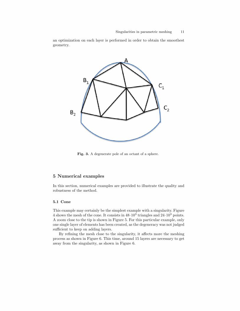
In order to generate the points, the middle point of the singular edge inthe parametric domain is first computed. The direction normal and tangentialto the singular edge are computed. This middle point is the initial guess ofa zeroth order smoothing where the smoothing is applied independently inboth directions. The normal direction allows the current point to be closeror further to the singularity. The tangential direction controls roughly theorthoradial direction close to the singularity only. Beginning from both endpoints of the edges that abut on the singularity, which may be the same pointin the three dimensional space, the point that is at a given distance of thelayer from the singularity and at equidistance from the two edge points issought. If no distance is violated, the point is stored and the same approach isperformed recursively. In Figure 3, an octant of a sphere is represented with asingular pole. Relying on the first two edges AB1 and AC1 an average size iscomputed . The parametric edge B1C1 is split and the point equidistant fromB1 and C1 at the correct distance from the singularity is sought. The sameprocedure is repeated for both edges B1B2 and C1C2. The main difficultycomes from the fact that the mapping is highly distorted. A small change inthe parametric plane does not produce a small change in the three dimensionalspace. A local scale in the three dimensional space should be first found andall candidates points are created with this local length. The smoothing in thedirection towards the singularity is driven by the three dimensional distanceto the singularity. The distance in the direction tangential to the singularityis driven by the distance to the plane equidistant to the two ancestor points.
The connection of these points relies on the hierarchical character of theprevious point creation. A point is created from two ancestors and hencereceives a level number in this process corresponding to the depth of therecurrence. For the creation of each new stripe, a stack of new points is created.The goal is therefore to find the best way to connect these two stripes of points.For each two stripes of points, both stripes are scanned concurrently until amatch is obtained on the recurrence level. Once a match has been found, eachsubstripe is meshed with a local one dimensional advancing front procedureas it boils down to choosing a diagonal to connect both sub stripes. Finally,
Singularities in parametric meshing 11
an optimization on each layer is performed in order to obtain the smoothestgeometry.
Fig. 3. A degenerate pole of an octant of a sphere.
5 Numerical examples
In this section, numerical examples are provided to illustrate the quality androbustness of the method.
5.1 Cone
This example may certainly be the simplest example with a singularity. Figure4 shows the mesh of the cone. It consists in 48·103 triangles and 24·103 points.A zoom close to the tip is shown in Figure 5. For this particular example, onlyone single layer of elements has been created, as the degeneracy was not judgedsufficient to keep on adding layers.
By refining the mesh close to the singularity, it affects more the meshingprocess as shown in Figure 6. This time, around 15 layers are necessary to getaway from the singularity, as shown in Figure 6.
12 R. Aubry1, K. Karamete1, E. Mestreau1, and S. Dey2
Fig. 4. Cone example.
Fig. 5. Zoom on the cone tip.
5.2 Propeller wing
For this example, a highly twisted propeller wing has been chosen. The topol-ogy of the wing is complicated as only the trailing edge and the edge from thejunction with the body are present. The wing surface is therefore completelywrapped over the trailing edge. Furthermore, a singular point arises at the tipof the wing. The mesh is displayed in Figure 8. The mesh contains 24 · 103
points and 73 · 103 triangles and has been refined with regard to curvature. Azoom close to the tip of the wing is displayed on Figure 9 and another zoomshows the singularity on Figure 10. It is clearly seen that no artifacts in themesh appear, and a high quality mesh has been obtained close to the singular
Singularities in parametric meshing 13
Fig. 6. Refined cone.
Fig. 7. Zoom on the refined cone tip.
14 R. Aubry1, K. Karamete1, E. Mestreau1, and S. Dey2
point location. In this example, five layers have been needed to get away fromthe singularity.
Fig. 8. Mesh for a propeller wing.
Fig. 9. Zoom close to the tip of the propeller wing.
5.3 Generic fighter
This example illustrates the geometry of a generic fighter. It is composed of14 faces. The wing tips on the back are composed with one NURBS surfaceeach. The mesh is composed of 68 · 103 points and 137 · 103 triangles. Thewing and stabilizer of the fighter are displayed in Figures 12 and 13. Each ofthe wings and stabilizers have a singular point. Again, singularities have beenhandled properly.
Singularities in parametric meshing 15
Fig. 10. Tip of the singularity on the propeller wing.
Fig. 11. Mesh for a generic fighter.
Fig. 12. Close up of the wing fighter near the wing tip.
16 R. Aubry1, K. Karamete1, E. Mestreau1, and S. Dey2
Fig. 13. Close up of the wing fighter near the back of the fighter.
6 Conclusion
A new parametric meshing technique has been presented. Parts of the meshgeneration have been highlighted. Particular emphasis has been given to thetreatment of singularities in the parametric mapping, which cause havoc toparametric meshers. The main idea consists in relying only on zeroth orderinformation and creating semi structured layers of meshes around the singu-larities. Examples have been shown that illustrate the quality and robustnessof the method.
Acknowledgments
This work was partly supported by the DoD HPCMP CREATE Program. Wewould like to thank John Livingston from the CREATE AV-DaVinci team forproviding the geometries for the twisted wing and the fighter.
References
1. R. Aubry, G. Houzeaux, and M. Vazquez. A surface remeshing approach. Int.J. Num. Meth. Eng., 85(12):1475–1498, 2011.
2. R. Aubry and R Lohner. On the ’most normal’ normal. Comm. Num. Meth.Eng., 24(12):1641–1652, 2008.
3. I. Babuska and A.K. Aziz. On the angle condition in the finite element method.SIAM J. Num. Anal., 13:214–226, 1976.
4. T. Banchoff and S. Lovett. Differential geometry of curves and surfaces. Natick,MA, A.K. Peters, 2010.
5. H. Borouchaki and P. L. George. Maillage de surfaces parametriques. partie Iaspects theoriques. C. R. Acad. Sci., 7(34):833–837, 1997.
Singularities in parametric meshing 17
6. H. Borouchaki and P. Laug. Simplification of composite parametric surfacemeshes. Eng. Comput. (Lond.), 20(3):176–183, 2004.
7. H. Borouchaki, P. Laug, and P. L. George. Parametric surface meshing using acombined advancing-front generalized Delaunay approach. Int. J. Num. Meth.Eng., 49:233–259, 2000.
8. J. C. Cuilliere. An adaptive method for the automatic triangulation of 3Dparametric surfaces. Computer-Aided Design, 30(2):139–149, 1998.
9. P.L. George and H. Borouchaki. Triangulation de Delaunay et maillage. Hermes,Paris, 1998.
10. Z. Guan, J. Shan, Y. Zheng, and Y. Gu. An extended advancing front techniquefor closed surfaces mesh generation. Int. J. Num. Meth., 74(1):642–667, 2007.
11. W. Kuhnel. Differential Geometry, Curves – Surfaces – Manifolds. AMS StudentMathematical Library Series Vol. 16, American Math. Society, 2nd edition 2006,1998.
12. P. Laug. Some aspects of parametric surface meshing. Finite Element in Anal-ysis and Design., 46:216–226, 2010.
13. C.K. Lee. Automatic metric advancing front triangulation over curved surfaces.Eng. Comp., 17(1):48–74, 2000.
14. C.K. Lee and R.E. Hobbs. Automatic adaptive finite element mesh generationover rational b-spline surfaces. Comput. Struct., 69:577–608, 1998.
15. R. Lohner. Regridding surface triangulations. J. Comput. Phys., 126:1–10, 1996.16. R. Lohner. Applied Computational Fluid Dynamics Techniques: An Introduction
Based on Finite Element Methods. Wiley, 2008. Second edition.17. A. Loseille and R. Lohner. On 3D anisotropic local remeshing for surface, vol-
ume, and boundary layers. In Proc. in 18th International Meshing Roundtable,pages 611–630, 2009.
18. D.L. Marcum and N.P. Weatherill. Unstructured grid generation using iterativepoint insertion and local reconnection. AIAA J., 33(9):619–1625, 1995.
19. M.L. Merriam. An efficient advancing front algorithm for Delaunay triangula-tion. AIAA-1991-792, 1995.
20. K. Nakahashi and D. Sharov. Direct surface triangulation using the advancingfront method. AIAA-95-1686-CP, 1995.
21. J. Peraire, J. Peiro, and K. Morgan. Adaptive remeshing for three-dimensionalcompressible flow computations. J. Comput. Phys., 103:269–285, 1992.
22. S. Rippa. Long and thin triangles can be good for linear interpolation. SIAMJ. Numer. Anal., 29(1):257–270, 1992.
23. D. Rypl and P. Krysl. Triangulation of 3D surfaces. Engineering with Comput-ers, 13:87–98, 1997.
24. J.R. Tristano, S.J. Owen, and S.A. Canann. Advancing front surface meshgeneration in parametric space using a Riemannian surface definition. In IMR,pages 429–445, 1998.