41


1

2

3
DESIGN AND PERFORMANCE PARAMETERS
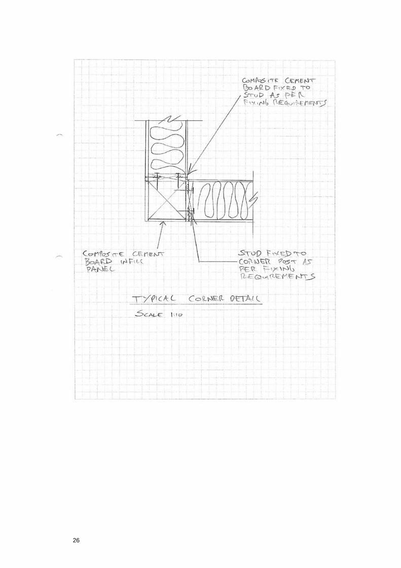
The construction process involves a prefabricated SIPS panel system. The panels are fixed to vertical
studs at 1200mm c/c. The studs are fixed down to a bottom rail and sole plate which is fixed down to a reinforced concrete base. The floors are formed in posi-joists spanning between the load-bearing walls.
2.1 Headbinders
At all floor levels a single C24 headbinder, lapped over wall panel junctions, is required in addition to the wall panel top rail. The headbinder is to be 50 x 250 for internal walls and 38 x 100 for external walls.
2.2 External and internal wall studs
External and internal SIPS wall are to have 47x250 C16 studs @1200c/c to form the permiter of each
panel. The studs are doubled up at each location with one stud per edge of each panel. All as shown on the engineer's drawings.
2.3 External and internal lintels
All external lintels dry graded members nailed together with dry graded C24 cripple studs under each end.
2.4 Non-loadbearing internal walls
Non loadbearing walls to be single 38x89 C16 studs @ 600 c/c. No plywood sheathing is required on these walls unless shown otherwise on engineer's drawings.
2.5 Stability
Stability is achieved by the external an internal walls acting as racking panels and from by connection
into the existing adjacent masonry building. The internal panels have 9mm MgO board fixed to both
faces of the prefabricated panels. The external panels have 12.5mm cement composite board fixed to
the external face and a 12.55 MgO board fixed to the internal face of the panel. For fixing requirements of the boards to the timber panel framing see below.
2.6 Plasterboard contribution to racking

4
Contribution of any plasterboard on all walls has been ignored.
2.7 Temporary support and bracing
Because plasterboard lining materials are generally fixed at a later date in the construction sequence,
checks have been made for short-term wind loads when no lining materials have been fixed. Wall
panels require temporary propping in the form of diagonal timbers nailed to the walls and fixed to the
decking/substructure to keep the walls vertical and in place until the horizontal diaphragm (floor or
roof) is in place and sheathed. The temporary bracing is to be in accordance with good timber frame
erecting practice (UKTFA guidance) and should be included in the timber frame erectors method statement.
2.8 Fire Resistance
The minimum required period of fire resistance for the building is 30 mins. It is therefore acceptable to allow the for full utilisation ratio on the internal studs in calculating their capacity.
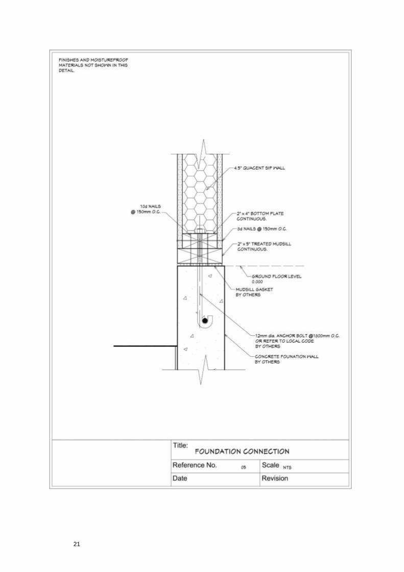
2.9 Soleplate
Soleplates are 50 x 250 C24 treated timber located a minimum of 150mm above external finished
ground level on the concrete foundation, fixed using shot fired pins, framing anchors or screws – refer to
fixings schedule attached.
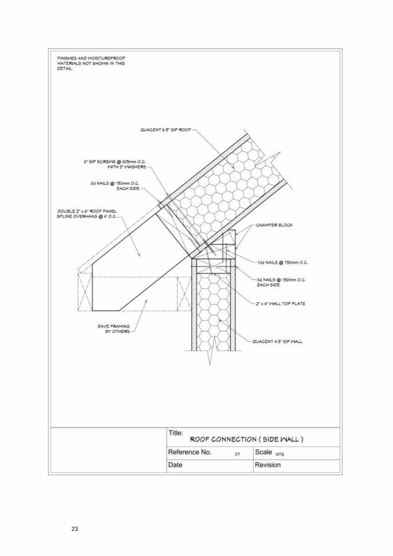
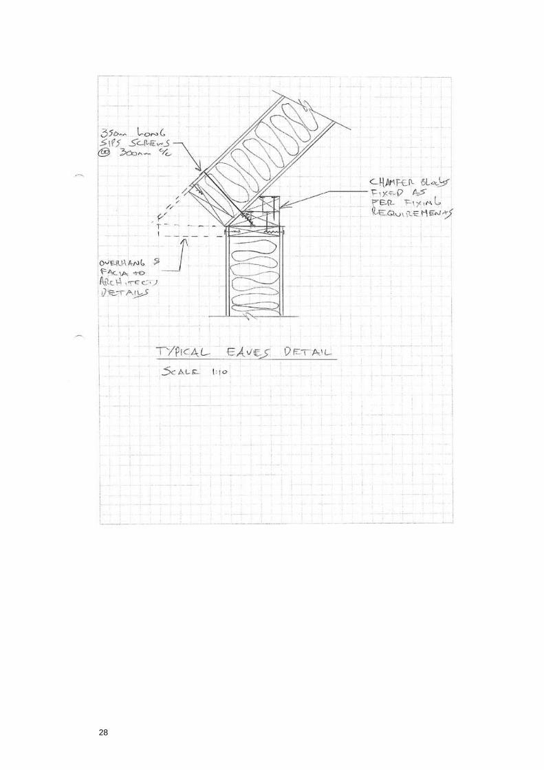
2.10 Roof
Roof joists have been designed by RISE and are shown on the drawings. Roof uplift resistance is to be
provided by 2.5mm thick restraint straps over headbinder/wallplate at 1200mm spacing fixed with a
minimum of 8 No. 3.1x90 long plain wire nails or 3.75 x 30 long square twist nails per strap to wall studs.
Note that the fixing design of all battens/firings and finishes against wind uplift is by others. The designs
are to be sent to RISE for their comments prior to construction of the roof and 5 working days should be allowed for the comments to be returned to the fabricators.
2.11 Cladding and Cavity Items
Coursing, setting-out & details, vertical movement joints, lintels, masonry tie specification, reinforcement are all by others.
Timber cavity barriers/closers and pinch battens to suit width of cavity at each cladding type for all openings, floor level firebreaks and compartment firebreaks, all to Architect’s Specification.
The cladding has been considered as render directly onto the external cement particle board supported by
the timber frame structure, should the load applied be any different, then the structural design will be affected and RISE should be notified immediately.
2.12 Disproportionate Collapse to Part A Building Regulations
The building is classed under Class 1. The building has been designed in accordance with Section 1 of The Building Regulations Approved Document A. Therefore no additional measures are required.
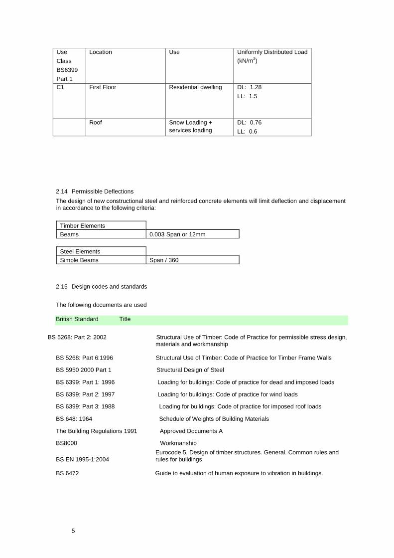
2.13 Occupancy Loads
The new construction will be designed in accordance with current British Standards, Codes of Practice
and Building Regulations, as listed in Section 2.1.4, in addition to specific requirements the occupier may request. The general design imposed loads for the buildings are as follows:
5
Use
Class
BS6399
Part 1
Location Use Uniformly Distributed Load
(kN/m2)
C1 First Floor Residential dwelling
DL: 1.28
LL: 1.5
Roof Snow Loading +
services loading
DL: 0.76
LL: 0.6
2.14 Permissible Deflections
The design of new constructional steel and reinforced concrete elements will limit deflection and displacement in accordance to the following criteria:
2.15 Design codes and standards
The following documents are used
British Standard Title
BS 5268: Part 2: 2002 Structural Use of Timber: Code of Practice for permissible stress design, materials and workmanship
BS 5268: Part 6:1996 Structural Use of Timber: Code of Practice for Timber Frame Walls
BS 5950 2000 Part 1 Structural Design of Steel
BS 6399: Part 1: 1996 Loading for buildings: Code of practice for dead and imposed loads
BS 6399: Part 2: 1997 Loading for buildings: Code of practice for wind loads
BS 6399: Part 3: 1988 Loading for buildings: Code of practice for imposed roof loads
BS 648: 1964 Schedule of Weights of Building Materials
The Building Regulations 1991 Approved Documents A
BS8000 Workmanship
Eurocode 5. Design of timber structures. General. Common rules and
BS EN 1995-1:2004 rules for buildings
BS 6472 Guide to evaluation of human exposure to vibration in buildings.
Timber Elements
Span or 12mm 0.003 Beams
Steel Elements
Simple Beams Span / 360

6
Other References
TRADA Timber Frame Book ‘Timber Frame Construction’ 3rd Edition 2001. British Steel corrosion protection
guide for building interiors and perimeter walls.
3.0 MATERIAL SPECIFICATIONS & WORKMANSHIP
3.1 Timber
All structural timbers are to be installed dry at moisture content of 18% with a variation of +2, -4% and to be graded in accordance with BS 4978 and BS 5268.
Timber is to be obtained from a managed, regulated and sustainable source. Tropical rainforest hardwoods will not be used.
3.2 Workmanship
Shall be in accordance with the relevant British Standards and specific references made in the NHBC Standards and the publication by TRADA, ‘Timber Frame Construction’ 3rd Edition 2001.
All members should be accurately cut to ensure firm contact along the abutting faces, and should be accurately cut to length to within a tolerance of± 1mm. No gaps over 2mm between abutting faces of timber.
Timber frame wall panels are to be fabricated so that horizontal and vertical dimensions are within +0, 3 mm of the size specified by the design.
All mechanical fasteners should be of the type and sizes specified and should be located so that the
specified spacing, end and edge distances are maintained. Nails or screws should be fully driven home
without undue damage to the surface of the materials being joined. No nail heads to penetrate the surface of the timber.
3.3 Preservative Treatment
Unless otherwise stated in this report, preservative treatment is required to the following members in accordance with the technical requirements of the NHBC standards and BS8417: 2003.
Hazard Classes 1-2:
• Ground Floor soleplates above DPC
• Pitched roofs: rafters, purlins, joists, and wallplates.
• Flat roofs: joists, decking, battens, firings, valley boards.
• External wall studs and rails.
• Ground Floor joists.
The following preservative treatments comply with these requirements: Organic Solvent (OS) Double Vacuum Treatment ref V4 (Ref BS5268 Part 5 – tables 4, 6 & 9) e.g. Protim Clearchoice by Osmose.
Hazard Classes 3-4:
• Balcony decking.
• Soleplates below DPC
• Barge boards and fascia boards
• External cladding
• External joinery
7
The following preservative treatments comply with these requirements: Copper-based preservative e.g. Osmose Naturewood.
Treat any cut ends with an appropriate cut end preservative.
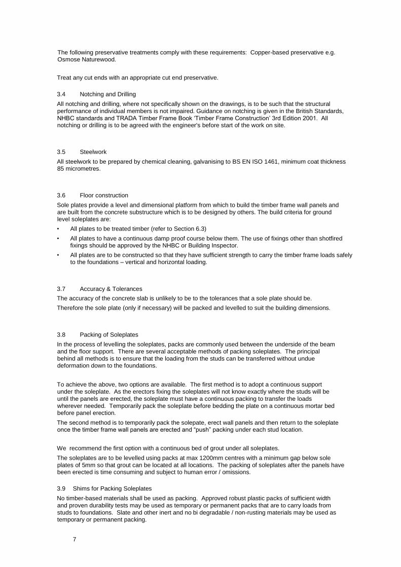
3.4 Notching and Drilling
All notching and drilling, where not specifically shown on the drawings, is to be such that the structural
performance of individual members is not impaired. Guidance on notching is given in the British Standards,
NHBC standards and TRADA Timber Frame Book ‘Timber Frame Construction’ 3rd Edition 2001. All notching or drilling is to be agreed with the engineer's before start of the work on site.
3.5 Steelwork
All steelwork to be prepared by chemical cleaning, galvanising to BS EN ISO 1461, minimum coat thickness 85 micrometres.
3.6 Floor construction
Sole plates provide a level and dimensional platform from which to build the timber frame wall panels and
are built from the concrete substructure which is to be designed by others. The build criteria for ground level soleplates are:
• All plates to be treated timber (refer to Section 6.3)
• All plates to have a continuous damp proof course below them. The use of fixings other than shotfired fixings should be approved by the NHBC or Building Inspector.
• All plates are to be constructed so that they have sufficient strength to carry the timber frame loads safely to the foundations – vertical and horizontal loading.
3.7 Accuracy & Tolerances
The accuracy of the concrete slab is unlikely to be to the tolerances that a sole plate should be.
Therefore the sole plate (only if necessary) will be packed and levelled to suit the building dimensions.
3.8 Packing of Soleplates
In the process of levelling the soleplates, packs are commonly used between the underside of the beam
and the floor support. There are several acceptable methods of packing soleplates. The principal
behind all methods is to ensure that the loading from the studs can be transferred without undue deformation down to the foundations.
To achieve the above, two options are available. The first method is to adopt a continuous support
under the soleplate. As the erectors fixing the soleplates will not know exactly where the studs will be
until the panels are erected, the soleplate must have a continuous packing to transfer the loads
wherever needed. Temporarily pack the soleplate before bedding the plate on a continuous mortar bed before panel erection.
The second method is to temporarily pack the solepate, erect wall panels and then return to the soleplate once the timber frame wall panels are erected and “push” packing under each stud location.
We recommend the first option with a continuous bed of grout under all soleplates.
The soleplates are to be levelled using packs at max 1200mm centres with a minimum gap below sole
plates of 5mm so that grout can be located at all locations. The packing of soleplates after the panels have been erected is time consuming and subject to human error / omissions.
3.9 Shims for Packing Soleplates
No timber-based materials shall be used as packing. Approved robust plastic packs of sufficient width
and proven durability tests may be used as temporary or permanent packs that are to carry loads from
studs to foundations. Slate and other inert and no bi degradable / non-rusting materials may be used as temporary or permanent packing.
8
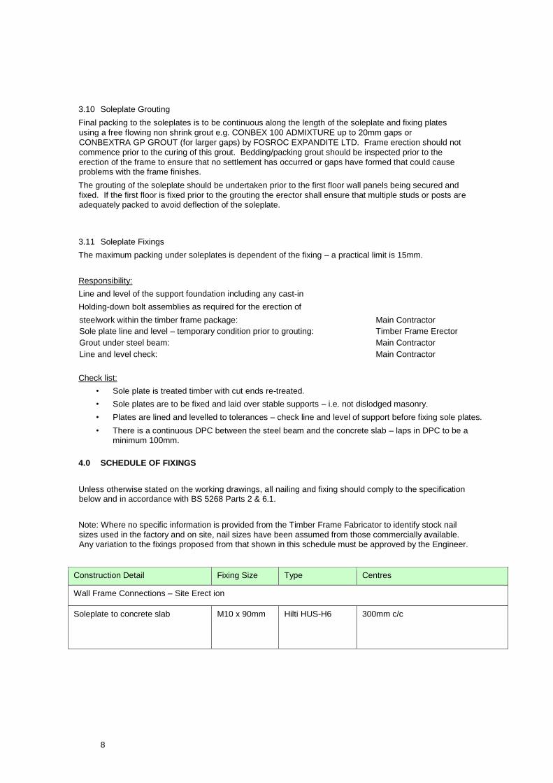
3.10 Soleplate Grouting
Final packing to the soleplates is to be continuous along the length of the soleplate and fixing plates
using a free flowing non shrink grout e.g. CONBEX 100 ADMIXTURE up to 20mm gaps or
CONBEXTRA GP GROUT (for larger gaps) by FOSROC EXPANDITE LTD. Frame erection should not
commence prior to the curing of this grout. Bedding/packing grout should be inspected prior to the
erection of the frame to ensure that no settlement has occurred or gaps have formed that could cause problems with the frame finishes.
The grouting of the soleplate should be undertaken prior to the first floor wall panels being secured and
fixed. If the first floor is fixed prior to the grouting the erector shall ensure that multiple studs or posts are adequately packed to avoid deflection of the soleplate.
3.11 Soleplate Fixings
The maximum packing under soleplates is dependent of the fixing – a practical limit is 15mm.
Responsibility:
Line and level of the support foundation including any cast-in
Holding-down bolt assemblies as required for the erection of
steelwork within the timber frame package: Main Contractor
Sole plate line and level – temporary condition prior to grouting: Timber Frame Erector
Grout under steel beam: Main Contractor
Line and level check: Main Contractor
Check list:
• Sole plate is treated timber with cut ends re-treated.
• Sole plates are to be fixed and laid over stable supports – i.e. not dislodged masonry.
• Plates are lined and levelled to tolerances – check line and level of support before fixing sole plates.
• There is a continuous DPC between the steel beam and the concrete slab – laps in DPC to be a minimum 100mm.
4.0 SCHEDULE OF FIXINGS
Unless otherwise stated on the working drawings, all nailing and fixing should comply to the specification below and in accordance with BS 5268 Parts 2 & 6.1.
Note: Where no specific information is provided from the Timber Frame Fabricator to identify stock nail
sizes used in the factory and on site, nail sizes have been assumed from those commercially available. Any variation to the fixings proposed from that shown in this schedule must be approved by the Engineer.
Construction Detail Fixing Size Type Centres
Wall Frame Connections – Site Erect ion
Soleplate to concrete slab
M10 x 90mm
Hilti HUS-H6
300mm c/c

9
Bottom panel rail to soleplate and
headbinder to top rail panel
Chamfer blocks to top rail
Chamfer Blocks to ridge beams
3.1x 75
3.1 x 90
Ring shank
annular
galvanised nails
200mm c/c
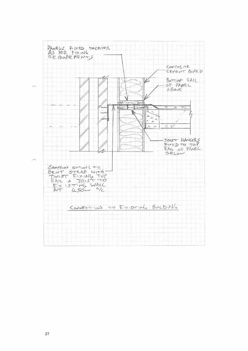
Panel to panel nailing, single stud
to single stud
Panel to panel nailing, multiple
studs to multiple studs
Panel to corner post
3.1x 75 at
300c/c
3.35x 75 at
300c/c
(BS5268-
6.1:1996
Cl4.9.2)
Ring shank
annular –
galvanised
Galv round wire
nails
300mm c/c
Skew nailed from alternate accessible
faces at 600mm c/c
Staircase Ledger Cullen Ledgerlo ck 82 long to be fixed to noggins behind top and bottom at
200c/c alternativ ely 45mm min edge distance per manufacturer’s
specification.
Wall Panels – Site fabrication
Stud to noggin 3.1x75 Galv round wire
nails
Ring shank
annular - galv
2 No. skew nailed.
Stud to top or bottom rail 4.0 x 75
3.1 x 75
Galv round wire
nails
Ring shank
annular - galv
2 No. End nailed.
Cripple studs / Multiple studs to
stud
3.1x75 Ring shank
annular - galv
at 300mm c/c
Stud to lintel end 4.0 x 75 3.1 x
75
Ring shank
annular - galv
4 No. Face nailed through stud.
Lintel to underside of top rail 4.0 x 75
3.1 x 75
Galv round wire
nails
Ring shank
annular - galv
At 300mm c/c through top rail.
Plate above and below openings. 4.0 x 75 Galv round wire 2 No. End/face nailed.
Construction Detail Fixing Size Type Centres
3.1 x 75
nails
Ring shank
annular - galv
Nailing together of 2/3 ply lintels. 4.0 x 75
3.1 x 75
Galv round wire
nails
Ring shank
annular - galv
at 300 centres staggered (face
nailed)

10
Composite cement board to timber
framing
4.0mm x
60mm
minimum
Stainless steel
screws
At 200mm centres on perimeter
framing members and 300mm
centres on internal framing members.
MgO board to timber framing 4.0mm x
60mm
minimum
Stainless steel
screws
At 200mm centres on perimeter
framing members and 300mm
centres on internal framing members
Nailed Plasterboard to frame.
(2nd fix site)
2.65 x 50 & 65
(outer layer)
Galv plasterboard
nails
At 150mm centres on all framing
members.
Screwed Plasterboard to frame.
(2nd fix site)
3.5min x
38mm (inner
layer)
3.5 x 60mm
(outer layer)
drywall screws At 300mm centres on all framing
members.
Floor Structure Connections – Site E rection
Joist blocking to internal wallplate/
headbinder*
3.1 x 90 Ring shank
annular – galv
Skew nailed at 150c/c in pairs.
Posijoist attachment at bearing
where no rim board or blocking
(Loose joists)*
3.35 x 75 Ring shank
annular – galv
2 nails (1 either side of joist) at
bearing, 40mm from end of joist
skewed into headbinder.
* An alternative fixing to skewed nail s from floor deck t o headbinder is to use Cullen Timberlok or Simpson SDS
self-drill coachscrews from the under side of the top pa nel rail upwards into the soffit of the floor
structure/beam/rimboard @ 600c/c. ADEQUATE FIXING OF FLOOR STRU CTURES TO WALLS IS ESSENTIAL
FOR BUILDING STABILITY – refer t o drawings.
Floors – Site Erection
Decking/Boarding to joists,
rimboards and blocking pieces.
Composite beams and trimmers
nailed together in-situ
3.1 x 50
3.1 x 90/3.75 x
95
Ring shank
annular - galv
Nailed and Glued
with Structural
PU Adhesive.
Ring shank
annular – galv
150 mm around perimeter and
300mm internal nail centres. All
boards to be to BS5268: Pt 2
orientated to suit the structural
direction. Decking to be fitted to suit
expansion (typically 1-2mm) per
panel and edge butting as
recommended by the manufacturer.
Free edges on noggins.
3 rows @ 300 c/c into face of
narrower beam. See details on
drawings.
Solid bridging or blocking and
Herringbone strutting
3.35 x 90 Ring shank
annular – galv
2: toe nailed, each end
1: face nailed, each end
Construction Detail Fixing Size Type Centres
Roof Construction (these are typical f ixing requirements only and must be read in conjunction with Roof drawings
and joist designer’s drawings/specific ation)

11
Wall plate to studs Cullen VRS 700-100 vertical restraint straps to provided around full roof
perimeter at1200c/c with 8No. 3.75 x 30mm nails to vertical studs and 2No.
3.75 x 30mm nails to wallplate.
12
5.0 CONSTRUCTION
5.1 Site constraints
If the new building is to be constructed in a residential area with narrow roads, space for storage of materials must be made available on site.
5.2 Crane
If there are any proposals for a crane and its support are to be submitted by the Contractor for the main
engineer to check. The contractor is to design the support of the crane and should arrange for check for any underground services on site.
5.3 Temporary works
When temporary bracing is required to members and assemblies and must be considered in the construction planning by the contractor especially due to the position of the building to be erected.
Bracing is used in broad sense and includes struts, ties, stabilising guys, shoring etc.
The contractor is to propose a sequence of works that includes their assessment and proposals for
temporary works. The main Engineer will make comment on these proposals before any works are carried out and these should be incorporated in the contractor’s proposals.
The building is stable only when all the shear walls and floors are built and fully connected.
If temporary propping is required (i.e. diagonal timbers nailed to the walls and fixed to the decking) to
keep the walls vertical and in place until the horizontal diaphragm (floor or roof) is fully in place and
sheathed. Temporary bracing is to be in accordance with good timber frame erecting practice (UKTFA
guidance) and should be included in the contractor method statement.
In addition, vertical restraint is to be provided at the staircase walls until the stairs are fully nailed tight to both sides of the wall.
All wall panels should be temporary propped horizontally at the toe of the panel until another wall panel perpendicular and fully connected to the latest provides stability.
No erection is to be carried out during strong winds and temporary propping are to be checked, strengthened at the beginning and ends of each shifts and at least a couple of times a day during week-ends.
The above is to be read in conjunction with the Design Safety Assessment in Appendix A.
It is assumed that the project is to be undertaken by experienced and competent contractors who are
aware of the common risks associated with construction processes within the prefabricated timber platform frame industry.
5.4 Fire
Timber frame is vulnerable to fire by vandalism or tradesmen causing over heating of timber, for example
use of blowtorches, blunt drills. Precautions should be made to minimise the risk. (Refer to UKTFA Fire Risk Members Briefing).
5.5 Rain/Flooding
Timber frame is installed at moisture contents of about 18% although some pieces may be at 20% during
the winter months. Sole plates can become saturated if standing water is allowed. The timber should be protected from getting wet as is reasonably practical and standing water avoided.

13
Plaster boarding and closing in of timber frame should be carried out only when the moisture content of
the timber is below 16%. Closing-in of damp timber may lead to mould growth and in some instances
decay.
Saturated timber-based deck boards (e.g. OSB, Chipboard and Plywood) are to be replaced as they will not shrink back to shape and they will lose strength.
Saturated I joists, Glulam, Kerto, Timber strand, Parallam and other proprietary engineered timber
products are to be replaced. All these products require protection from driving rain. Drying-down of these products will create problems with performance.
The use of taped joints on chipboard/OSB board decking will not guarantee that water will not seep into
joints but may reduce the chances. Taped joints are to be maintained and standing water avoided. Open
windows, gaps are sources of water ingress and the use of Visqueen should be made to protect openings before windows are installed.
5.6 Storage of Materials
Storage of timber frame panels, truss rafters, loose timber, engineered timber etc is to be carried out so that members are not in contact with the ground and are covered against driving rain (ventilated covers).
5.7 Gantries and scaffold
Gantries and scaffolds might be required and tied back to the timber structure once it is fully erected.
Connection details should be agreed with Engineer prior start work on site. All gantries and scaffold should be fully inspected and approved before their usage.
5.8 Envisaged sequence of works
The contractor is to submit a Sequence of Work with his safety assessment before work start on site.
5.9 General Construction issues
Drained and ventilated cavities for the timber frame are essential for good timber frame performance. In
no circumstances is timber frame to be erected in horizontal contact with masonry/concrete, even with DPM membranes. All cavities are to be checked and approved before closing up.
It is the responsibility of the Architect and Substructure Engineer to ensure that all structural timber,
irrespective of its preservative treatment or detailing, should be located a minimum of 150mm above
finished ground level as recommended by TRADA and insuring bodies such as NHBC and CRL. This
can have a number of effects on the detailing of the lower storey of timber frame wall panels, often
requiring ‘durable’ plinths of concrete or blockwork to be provided around the full external perimeter of the building to lift the timber frame elements 150mm above FGL.

14
6.0 BUILD TOLERANCES
Full guidance on tolerances for timber frame construction is given in the TRADA Technology “Timber frame construction”. Additional considerations that are presented as follows:
Support structure/
foundation
Tolerances Lengths of support structure beneath the timber frame sole plate to
be within +/- 10 mm.
Diagonals should be equal. Acceptable deviation is up to 10 m: +/-
5mm more than 10 m: +/- 10 mm
Walls/beams or slab supporting sole plates are levelled to +/- 5 mm.
Construction
Notes
Underground ducts for plumbing stacks to rise clear of floor joists,
columns/beams, and trussed rafters.
Position and secure metal fixing plates and baseplates to
foundations or slab as specified, check that they are adequately
protected by hot dip galvanizing or bitumen paint, or have equal
corrosion resistance.
Check in advance if Main Contractor requires Timber Frame
Contractor to provide Holding-down bolt assemblies for casting-in.
Check on site that assemblies have been correctly installed by Main
Contractor.
Soleplates and
bottom rails of wall
panels
Tolerances Sole plates should be set out within +/- 10 mm in length or width
defined by the drawings. Diagonals should be equal. Acceptable
deviation is:
up to 10 m: +/- 5 mm; 10 -
20 m: +/- 10 mm.
Above 20m length - +/- 15 mm.
Diagonals should be equal. Acceptable deviation is up to 10 m: +/-
5mm more than 10 m: +/- 10 mm
The sole plates should not overhang the support structure/
foundation by more than 10 mm.
Sole plates must be level within +/- 5 mm.
Construction
Notes
Fully bed the plates on mortar (and structural shims if necessary) if
base is not level. For sole plates packing to be solid and NOT timber
off cuts, or board material (plywood etc). Maximum packing to be
20mm. Bedding and shims should be approved by the project
structural engineer. Non-biodegradable rigid plastic packs are an
example of acceptable packing – see Packing of Soleplates
Section 6.5
Sole plate/bottom rail should be surveyed and corrected for line and
level at each storey height
The sole plates are pressure treated with preservative where
specified and brush apply preservative to site cut ends and drilled
holes.
Where appropriate ensure that there is a DPC under sole plates
lapped 100 mm at joints and overlapping the DPM.
Fixings Type, number and centres of fixings as specified by The Fixing
Schedule.
If mild steel brackets, shoes, straps and/or if disproportionate
collapse plates have been specified, check that they are adequately
protected by hot dip galvanizing, or have equal corrosion resistance.
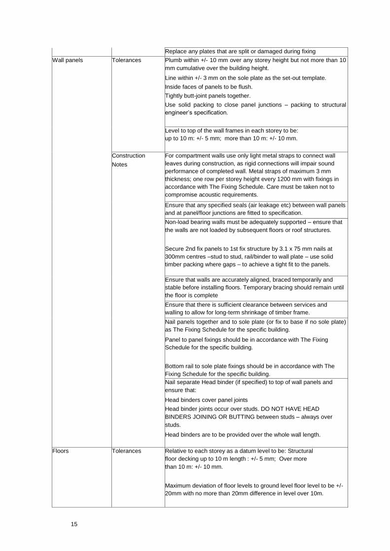
15
Replace any plates that are split or damaged during fixing
Wall panels Tolerances Plumb within +/- 10 mm over any storey height but not more than 10
mm cumulative over the building height.
Line within +/- 3 mm on the sole plate as the set-out template.
Inside faces of panels to be flush.
Tightly butt-joint panels together.
Use solid packing to close panel junctions – packing to structural
engineer’s specification.
Level to top of the wall frames in each storey to be:
up to 10 m: +/- 5 mm; more than 10 m: +/- 10 mm.
Construction
Notes
For compartment walls use only light metal straps to connect wall
leaves during construction, as rigid connections will impair sound
performance of completed wall. Metal straps of maximum 3 mm
thickness; one row per storey height every 1200 mm with fixings in
accordance with The Fixing Schedule. Care must be taken not to
compromise acoustic requirements.
Ensure that any specified seals (air leakage etc) between wall panels
and at panel/floor junctions are fitted to specification.
Non-load bearing walls must be adequately supported – ensure that
the walls are not loaded by subsequent floors or roof structures.
Secure 2nd fix panels to 1st fix structure by 3.1 x 75 mm nails at
300mm centres –stud to stud, rail/binder to wall plate – use solid
timber packing where gaps – to achieve a tight fit to the panels.
Ensure that walls are accurately aligned, braced temporarily and
stable before installing floors. Temporary bracing should remain until
the floor is complete
Ensure that there is sufficient clearance between services and
walling to allow for long-term shrinkage of timber frame.
Nail panels together and to sole plate (or fix to base if no sole plate)
as The Fixing Schedule for the specific building.
Panel to panel fixings should be in accordance with The Fixing
Schedule for the specific building.
Bottom rail to sole plate fixings should be in accordance with The
Fixing Schedule for the specific building.
Nail separate Head binder (if specified) to top of wall panels and
ensure that:
Head binders cover panel joints
Head binder joints occur over studs. DO NOT HAVE HEAD
BINDERS JOINING OR BUTTING between studs – always over
studs.
Head binders are to be provided over the whole wall length.
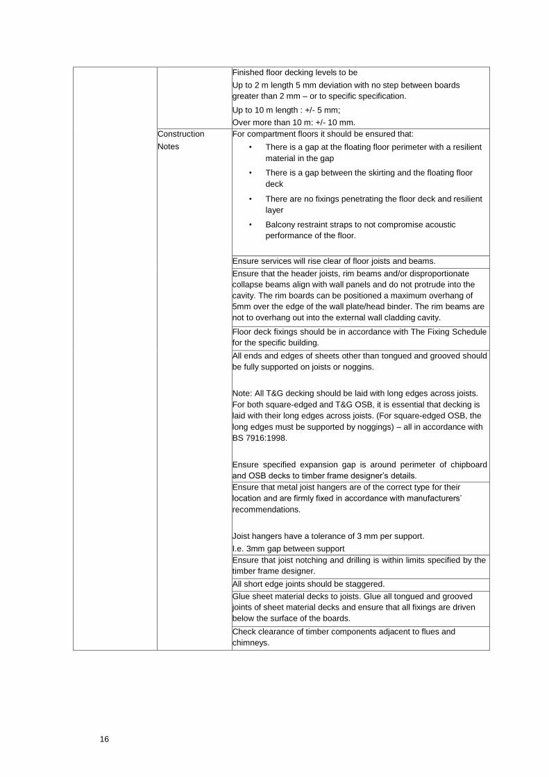
Floors Tolerances Relative to each storey as a datum level to be: Structural
floor decking up to 10 m length : +/- 5 mm; Over more
than 10 m: +/- 10 mm.
Maximum deviation of floor levels to ground level floor level to be +/-
20mm with no more than 20mm difference in level over 10m.
16
Finished floor decking levels to be
Up to 2 m length 5 mm deviation with no step between boards
greater than 2 mm – or to specific specification.
Up to 10 m length : +/- 5 mm;
Over more than 10 m: +/- 10 mm.
Construction
Notes
For compartment floors it should be ensured that:
• There is a gap at the floating floor perimeter with a resilient
material in the gap
• There is a gap between the skirting and the floating floor
deck
• There are no fixings penetrating the floor deck and resilient
layer
• Balcony restraint straps to not compromise acoustic
performance of the floor.
Ensure services will rise clear of floor joists and beams.
Ensure that the header joists, rim beams and/or disproportionate
collapse beams align with wall panels and do not protrude into the
cavity. The rim boards can be positioned a maximum overhang of
5mm over the edge of the wall plate/head binder. The rim beams are
not to overhang out into the external wall cladding cavity.
Floor deck fixings should be in accordance with The Fixing Schedule
for the specific building.
All ends and edges of sheets other than tongued and grooved should
be fully supported on joists or noggins.
Note: All T&G decking should be laid with long edges across joists.
For both square-edged and T&G OSB, it is essential that decking is
laid with their long edges across joists. (For square-edged OSB, the
long edges must be supported by noggings) – all in accordance with
BS 7916:1998.
Ensure specified expansion gap is around perimeter of chipboard
and OSB decks to timber frame designer’s details.
Ensure that metal joist hangers are of the correct type for their
location and are firmly fixed in accordance with manufacturers’
recommendations.
Joist hangers have a tolerance of 3 mm per support.
I.e. 3mm gap between support
Ensure that joist notching and drilling is within limits specified by the
timber frame designer.
All short edge joints should be staggered.
Glue sheet material decks to joists. Glue all tongued and grooved
joints of sheet material decks and ensure that all fixings are driven
below the surface of the boards.
Check clearance of timber components adjacent to flues and
chimneys.

17
Internal movement
joints
At stair case floor zones – ensure differential movement joint in
plasterboard at floor zone with fire-backed mastic joint.
At internal wall to external wall junctions – vertical plasterboard joint
to have mastic junction to allow small differential movement of
external panel relative to internal panel.
Delivery of
components
The wall frames, floor joists, decking, floor panels and trussed
rafters or loose rafters should be checked and recorded on delivery
for:
• Location identification labels (block number, floor number,
unit number, layout location, orientation of component).
• Quality of material, strength grading marks/stamping and
moisture resistance grade of decking, linings etc.
• Quality of assembly (correct nailing and jointing for the
specific building).
• Correctly dimensioned within stated tolerances.
• Moisture content and preservative treatment schedules
(where applicable)
Components to be stacked off ground in reverse order of use, on
level dry area to avoid soiling and distortion. Protect from rainwater
and ground moisture but allow adequate ventilation.
Erection Notes Sequence By timber frame fabricator. Programme of fabrication and erection
to be submitted.
A construction sequence that provides early handover of part of the
buildings for services and plasterboard fit out is to be adopted.
Temporary
bracing
The building does not require any temporary bracing once erected
as the design allows for Category 1 sheathed wall panels to provide
adequate stability both in the temporary and final condition.
Some panel stability bracing will be required during early panel
erection per floor level.
Scaffolding Safe scaffolding to be provided around building during construction and lifting of panels.
Ensure that scaffolding lateral restraint fixings to timber frame structure are approved. –
Details to be provided by Scaffolding erector/Main Contractor for approval of the
Structural Engineer prior to erection.
Plasterboard
Loading- Out
Contractor to submit loading out statement and location – Project is not designed for
loaded zones, extra studs or sheathing may be required.
Loaded areas to be a maximum of 200kg/sq.m or temporary props installed to support
material packs through all floors to a suitable foundation and adequate temporary
bracing provided. Proposals to be submitted to CCB for approval / instruction.

18
Protection Of
Works From Rain
Weather protection of the as-built framing is to be adopted.
The Erector and Main Contractor must make every provision for protecting the works
during erection, and until adequately covered from the effects of moisture during periods
of prolonged rainfall.
Correct site storage of all materials must be in accordance with Trada Technology
publication ‘Timber Frame Construction’ 3rd Edition 2001
In particular any Engineered Timber beams or posts (LSL or PSL) must be adequately
covered in breather membrane until the floor deck is in place and firmly fixed down.
Do not lay Floating Floors if sub base is wet/damp – check with a moisture meter. Fix
and lay to Architects specification
7.0 DIFFERENTIAL MOVEMENT
Timber frame buildings will significantly shrink across floor zones during construction and during the first 36 months of occupation.
The minimum movement joint sizes to allow for movements of the timber frame are to be as follows:
Level (mm)
Roof/Eaves 12.0
8th Floor window cill level 9.0
7th Floor window cill level 3.0
These estimates are for total downwards movement from the timber superstructure and are exclusive of brickwork movement and exclude for any upwards gain due to lack of fit.
7.1 Cladding Detailing
The shrinkage of the timber frame must be accommodated in the cladding and lining system by providing
horizontal movement joints between the cladding panels at suitable locations at floor levels. Battens for
cladding that are fixed to the timber frame are not to be fixed continuously over the full building height - a
10mm gap should be introduced at each floor zone.
Lower level movement – As the frame shrinks the supported elements of cladding will move with it.
Any abutment at the base of the cladding (e.g. at the junction with a terrace, low level roof or
groundsupported cladding) will also require sufficient movement capacity to take up this frame shrinkage. Cladding supported independently of the timber frame (e.g. Clay Masonry, blockwork).
The shrinkage of the timber frame must be accommodated by providing movement joints between the
cladding and the timber frame at suitable locations, usually at window cills, at eaves level and at the bottom
of any openings. Cladding wall ties must also be designed to accommodate the timber frame shrinkage.
Plasterboard within stair wells or continuous shafts should not be fixed in across floor zones. A minimum
10mm horizontal movement joint + suitable cover strip should be introduced at each floor zone. To maintain fire integrity, this MJ should occur on a solid floor edge member.

19
Examples of Fixing

20
21

22
23

24

25
SUPERIOR SIPs
26
27
28

29
30
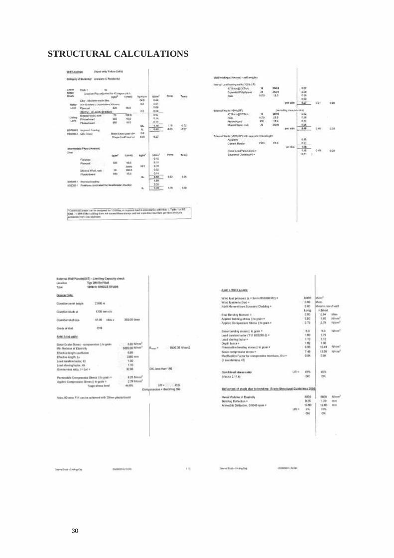
STRUCTURAL CALCULATIONS

31
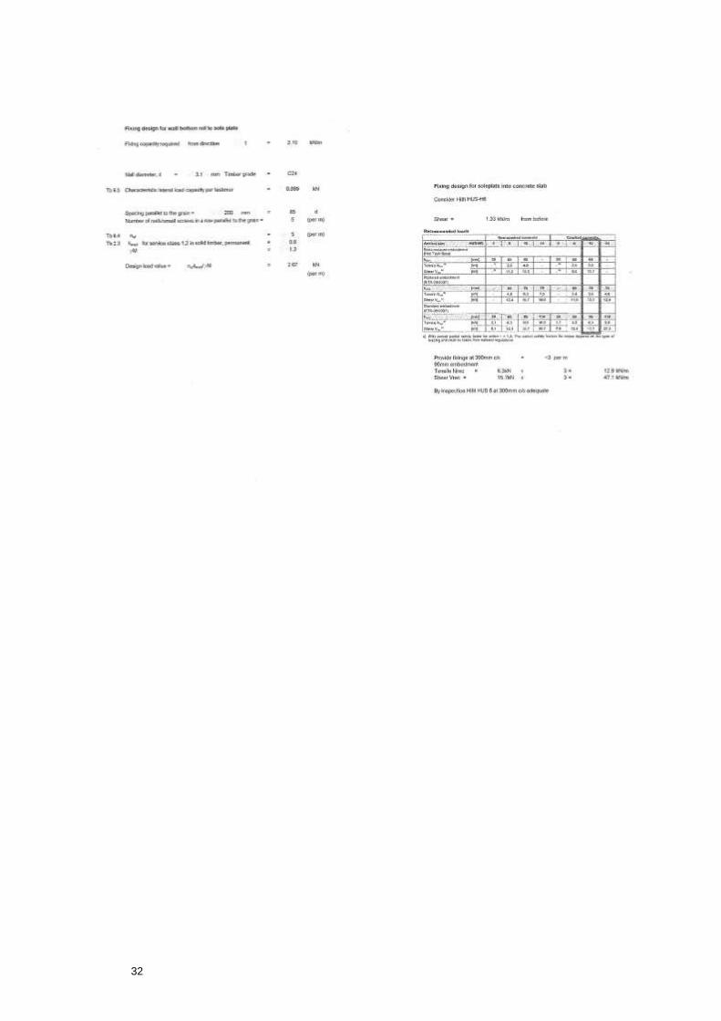
32
33
Melin Consultants Ltd, The Beacon, Dafen Business Park, Llanelli, SA14 8LQ
0845 094 1593 ; [email protected]
Documentation of the component 14 . October 2013
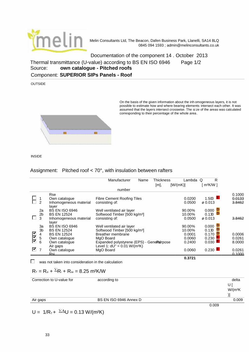
Thermal transmittance (U-value) according to BS EN ISO 6946 Page 1/2 Source: own catalogue - Pitched roofs
Assignment: Pitched roof < 70°, with insulation between rafters
Manufacturer Name Thickness Lambda Q R
[m], [W/(mK)] [ m²K/W ]
number
Correction to U-value for according to delta
U [
W/(m²K
)]
Air gaps BS EN ISO 6946 Annex D 0.009
0.009
U = 1/RT + U = 0.13 W/(m²K)
Rse 0.1000 1.50 0.0200 Fibre Cement Roofing Tiles Own catalogue 1 0 0.0133
Inhomogeneous material 2 layer
consisting of: 3.8462 ø 0.013 0.0500
BS EN ISO 6946 2 a Well ventilated air layer 90.00 % 0 .000 0.13 % 10.00 Softwood Timber [500 kg/m³] BS EN 12524 b 2 0
Inhomogeneous material 3 layer
consisting of: 0.0500 3.8462 ø 0.013
Well ventilated air layer 90.00 % 0 3 a BS EN ISO 6946 .000 % 0.13 3 b BS EN 12524 Softwood Timber [500 kg/m³] 10.00 0
4 BS EN 12524 Breather membrane 0.0001 0.170 0.0006 5 Own catalogue MgO Board 0.230 0.0060 0.0261 6 Own catalogue Expanded polystyrene (EPS) - General Purpose 0.2400 0.030 8.0000
Air gaps Level 1: dU'' = 0.01 W/(m²K) Own catalogue MgO Board 7 0.230 0.0060 0.0261 Rsi 0.1000
0.3721 was not taken into consideration in the calculation
R T = R si + R i R + se = 8.25 m²K/W
Component: SUPERIOR SIPs Panels - Roof
OUTSIDE
INSIDE
On the basis of the given information about the inh omogeneous layers, it is not possible to estimate how and where bearing elements intersect each other. It was assumed that the layers intersect crosswise. The si ze of the areas was calculated corresponding to their percentage of the whole area .

34
Q .. The physical values of the building materials has been graded by their level of
quality. These 5 levels are the following .. A: Data is entered and validated by the
manufacturer or supplier. Data is continuously tested by 3rd party. .. B: Data is entered and
validated by the manufacturer or supplier. Data is certified by 3rd party .. C: Data is entered and validated by the manufacturer or supplier.
.. D: Information is entered by BuildDesk without special agreement with the manufacturer, supplier or others.
.. E: Information is entered by the user of the BuildDesk software without special agreement with the manufacturer, supplier or others.
Calculated with BuildDesk 3.4.5
35
The Beacon, Dafen Business Park, Llanelli, SA14 8LQ
0845 094 1593 ; [email protected]
Documentation of the component 14 . October 2013
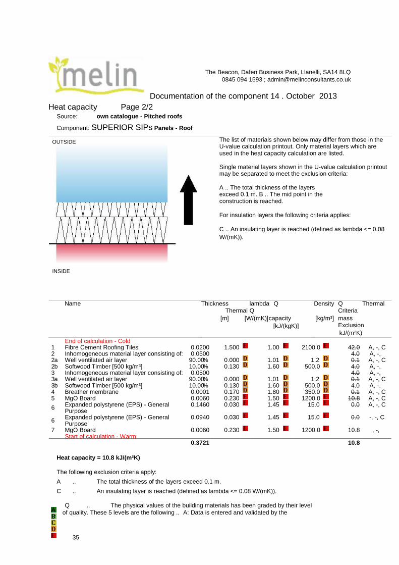
Heat capacity Page 2/2
Source: own catalogue - Pitched roofs
Component: SUPERIOR SIPs Panels - Roof
The list of materials shown below may differ from those in the U-value calculation printout. Only material layers which are used in the heat capacity calculation are listed.
Single material layers shown in the U-value calculation printout may be separated to meet the exclusion criteria:
A .. The total thickness of the layers exceed 0.1 m. B .. The mid point in the construction is reached.
For insulation layers the following criteria applies:
C .. An insulating layer is reached (defined as lambda <= 0.08
W/(mK)).
Name Thickness lambda Q Thermal Q
[m] [W/(mK)] capacity
[kJ/(kgK)]
Density Q Thermal Criteria
[kg/m³] mass Exclusion
kJ/(m²K)
Heat capacity = 10.8 kJ/(m²K)
The following exclusion criteria apply:
A .. The total thickness of the layers exceed 0.1 m.
C .. An insulating layer is reached (defined as lambda <= 0.08 W/(mK)).
Q .. The physical values of the building materials has been graded by their level
of quality. These 5 levels are the following .. A: Data is entered and validated by the
End of calculation - Cold 0.0200 1.500 Fibre Cement Roofing Tiles 1 1.00 2100.0 42.0 A, -, C
2 Inhomogeneous material layer consisting of: 0.0500 4.0 A, -, 2 a Well ventilated air layer 90.00 % 0.000 1.01 1.2 0.1 A, -, C 2 b Softwood Timber [500 kg/m³] 10.00 % 0.130 1.60 500.0 4.0 A, -,
0.0500 3 Inhomogeneous material layer consisting of: 4.0 A, -, 3 a Well ventilated air layer 90.00 % 0.000 1.01 1.2 0.1 A, -, C
0.130 3 b Softwood Timber [500 kg/m³] 10.00 % 1.60 500.0 4.0 A, -, 4 0.170 0.0001 Breather membrane 1.80 350.0 0.1 A, -, C
MgO Board 5 0.230 0.0060 1.50 1200.0 10.8 A, -, C
6 Expanded polystyrene (EPS) - General Purpose
0.1460 0.030 1.45 15.0 0.0 A, -, C
6 Expanded polystyrene (EPS) - General Purpose
0.0940 0.030 1.45 15.0 0.0 - , -, C
7 MgO Board 0.0060 0.230 1.50 1200.0 10.8 , -, Start of calculation - Warm
0.3721 10.8
OUTSIDE
INSIDE

36
manufacturer or supplier. Data is continuously tested by 3rd party. .. B: Data is entered
and validated by the manufacturer or supplier. Data is certified by 3rd party .. C: Data is entered and validated by the manufacturer or supplier.
.. D: Information is entered by BuildDesk without special agreement with the manufacturer, supplier or others.
.. E: Information is entered by the user of the BuildDesk software without special agreement with the manufacturer, supplier or others.
Calculated with BuildDesk 3.4.5
37
Melin Consultants Ltd, The Beacon, Dafen Business Park, Llanelli, SA14 8LQ
0845 094 1593 ; [email protected]
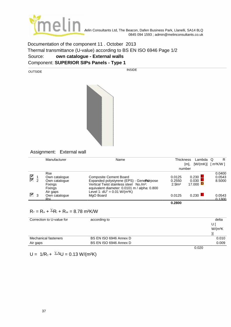
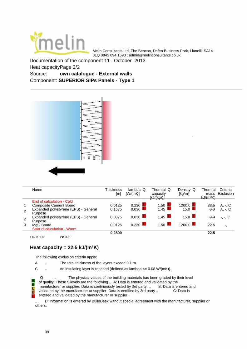
Documentation of the component 11 . October 2013
Thermal transmittance (U-value) according to BS EN ISO 6946 Page 1/2
Source: own catalogue - External walls
Component: SUPERIOR SIPs Panels - Type 1
OUTSIDE
INSIDE
Manufacturer Name Thickness
[m],
number
Lambda Q R
[W/(mK)] [ m²K/W ]
Correction to U-value for according to delta
U [
W/(m²K
)]
Mechanical fasteners BS EN ISO 6946 Annex D 0.010
Air gaps BS EN ISO 6946 Annex D 0.009
0.020
U = 1/RT + U = 0.13 W/(m²K)
Rse 0.0400 0.0125 0.230 1 Own catalogue Composite Cement Board 0.0543
2 Own catalogue Expanded polystyrene (EPS) - General Purpose 0.2550 0.030 8.5000 2.5 / Fixings Vertical Twist stainless steel No./m²: m² 17.000
Fixings equivalent diameter: 0.0101 m / alpha: 0.800 Air gaps Level 1: dU'' = 0.01 W/(m²K)
3 Own catalogue MgO Board 0.0125 0.230 0.0543 Rsi 0.1300
0.2800
R T = R si + R i + R se = 8.78 m²K/W
Assignment: External wall
38
Q .. The physical values of the building materials has been graded by their level
of quality. These 5 levels are the following .. A: Data is entered and validated by the
manufacturer or supplier. Data is continuously tested by 3rd party. .. B: Data is entered and
validated by the manufacturer or supplier. Data is certified by 3rd party .. C: Data is entered and validated by the manufacturer or supplier.
.. D: Information is entered by BuildDesk without special agreement with the manufacturer, supplier or
others.
.. E: Information is entered by the user of the BuildDesk software without special agreement with the manufacturer, supplier or others.
39
Melin Consultants Ltd, The Beacon, Dafen Business Park, Llanelli, SA14 8LQ 0845 094 1593 ; [email protected]
Documentation of the component 11 . October 2013
Heat capacityPage 2/2
Source: own catalogue - External walls
Component: SUPERIOR SIPs Panels - Type 1
OUTSIDE INSIDE
Heat capacity = 22.5 kJ/(m²K)
The following exclusion criteria apply:
A .. The total thickness of the layers exceed 0.1 m.
C .. An insulating layer is reached (defined as lambda <= 0.08 W/(mK)).
Q .. The physical values of the building materials has been graded by their level
of quality. These 5 levels are the following .. A: Data is entered and validated by the
manufacturer or supplier. Data is continuously tested by 3rd party. .. B: Data is entered and
validated by the manufacturer or supplier. Data is certified by 3rd party .. C: Data is entered and validated by the manufacturer or supplier.
.. D: Information is entered by BuildDesk without special agreement with the manufacturer, supplier or others.
.
Name Thickness [ ] m
lambda )] W/(mK [
Q Thermal capacity
)] kJ/(kgK [
Q Density [ ] kg/m³
Q Thermal mass
kJ/(m²K)
Criteria Exclusion
End of calculation - Cold Composite Cement Board 0.0125 0.230 1 1.50 1200.0 22.5 A, -, C
2 Expanded polystyrene (EPS) - General Purpose
0.1675 0.030 1.45 15.0 0.0 A, -, C
2 Expanded polystyrene (EPS) - General Purpose
0.030 0.0875 1.45 15.0 0.0 - , -, C
3 MgO Board 0.0125 0.230 1.50 1200.0 22.5 , -, Start of calculation - Warm
0.2800 22.5

40
.. E: Information is entered by the user of the BuildDesk software without special agreement with the manufacturer, supplier or others.
cCalculated with BuildDesk 3.4.5
N.B. Superior SIPs will arrange all Building Regulations with their LABC Partner, Powys Council, and supply Engineer’s Calculations and Reports.
10 Year CRL Structural Warranty is also included.
If required a complete project build from Ground Works to Finish Building can be arranged.
--------------------------------------------------


![WALLPLATES & HOUSINGS...4-Port Wallplate 43080-1S4 43080-2S4 3-Port Wallplate 43080-1S3 2-Port Wallplate 43080-1S2 43080-2S2 1-Port Wallplate 43080-1S1 [D] QUICKPORT STAINLESS STEEL](https://static.documents.pub/doc/80x56/5fe8532332ac636a9b7bbb72/wallplates-housings-4-port-wallplate-43080-1s4-43080-2s4-3-port-wallplate.jpg)