Americas Headquarters Cisco Systems, Inc. 170 West Tasman Drive San Jose, CA 95134-1706 USA http://www.cisco.com Tel: 408 526-4000 800 553-NETS (6387) Fax: 408 527-0883 Cisco BTS 10200 Softswitch SIP Feature and Provisioning Guide, Release 5.0 October 30, 2012 Customer Order Number: Text Part Number: OL-12397-18
Transcript
Cisco BTS 10200 Softswitch SIP Feature and Provisioning Guide, Release 5.0 October 30, 2012
Americas HeadquartersCisco Systems, Inc.170 West Tasman DriveSan Jose, CA 95134-1706 USAhttp://www.cisco.comTel: 408 526-4000
800 553-NETS (6387)Fax: 408 527-0883
Customer Order Number: Text Part Number: OL-12397-18
THE SPECIFICATIONS AND INFORMATION REGARDING THE PRODUCTS IN THIS MANUAL ARE SUBJECT TO CHANGE WITHOUT NOTICE. ALL STATEMENTS, INFORMATION, AND RECOMMENDATIONS IN THIS MANUAL ARE BELIEVED TO BE ACCURATE BUT ARE PRESENTED WITHOUT WARRANTY OF ANY KIND, EXPRESS OR IMPLIED. USERS MUST TAKE FULL RESPONSIBILITY FOR THEIR APPLICATION OF ANY PRODUCTS.
THE SOFTWARE LICENSE AND LIMITED WARRANTY FOR THE ACCOMPANYING PRODUCT ARE SET FORTH IN THE INFORMATION PACKET THAT SHIPPED WITH THE PRODUCT AND ARE INCORPORATED HEREIN BY THIS REFERENCE. IF YOU ARE UNABLE TO LOCATE THE SOFTWARE LICENSE OR LIMITED WARRANTY, CONTACT YOUR CISCO REPRESENTATIVE FOR A COPY.
NOTWITHSTANDING ANY OTHER WARRANTY HEREIN, ALL DOCUMENT FILES AND SOFTWARE OF THESE SUPPLIERS ARE PROVIDED “AS IS” WITH ALL FAULTS. CISCO AND THE ABOVE-NAMED SUPPLIERS DISCLAIM ALL WARRANTIES, EXPRESSED OR IMPLIED, INCLUDING, WITHOUT LIMITATION, THOSE OF MERCHANTABILITY, FITNESS FOR A PARTICULAR PURPOSE AND NONINFRINGEMENT OR ARISING FROM A COURSE OF DEALING, USAGE, OR TRADE PRACTICE.
IN NO EVENT SHALL CISCO OR ITS SUPPLIERS BE LIABLE FOR ANY INDIRECT, SPECIAL, CONSEQUENTIAL, OR INCIDENTAL DAMAGES, INCLUDING, WITHOUT LIMITATION, LOST PROFITS OR LOSS OR DAMAGE TO DATA ARISING OUT OF THE USE OR INABILITY TO USE THIS MANUAL, EVEN IF CISCO OR ITS SUPPLIERS HAVE BEEN ADVISED OF THE POSSIBILITY OF SUCH DAMAGES.
Cisco and the Cisco logo are trademarks or registered trademarks of Cisco and/or its affiliates in the U.S. and other countries. To view a list of Cisco trademarks, go to this URL: www.cisco.com/go/trademarks. Third-party trademarks mentioned are the property of their respective owners. The use of the word partner does not imply a partnership relationship between Cisco and any other company. (1110R)
Any Internet Protocol (IP) addresses used in this document are not intended to be actual addresses. Any examples, command display output, and figures included in the document are shown for illustrative purposes only. Any use of actual IP addresses in illustrative content is unintentional and coincidental.
This document describes the features applicable to Session Initiation Protocol (SIP) devices, subscribers, and trunks. It also provides the procedures necessary to provision these features.
Revision History for this DocumentThis document incorporates all of the information that was contained in the previous SIP Guides for Release 4.5.x—the Cisco BTS 10200 Softswitch SIP Protocol User Guide and the Cisco BTS 10200 Softswitch SIP Protocol Provisioning Guide. In addition, it provides information on all Release 5.0 features.
Release Changes
Release 5.0 In version OL-12397-18, the “Provisioning Session Timers for SIP Subscribers” was updated.
Release 5.0 In version OL-12397-17, the “Detailed Description of Timers” section on page 4-2 was updated.
Release 5.0 In version OL-12397-16, the “Call Redirection Provisioning” section on page 3-24 was updated.
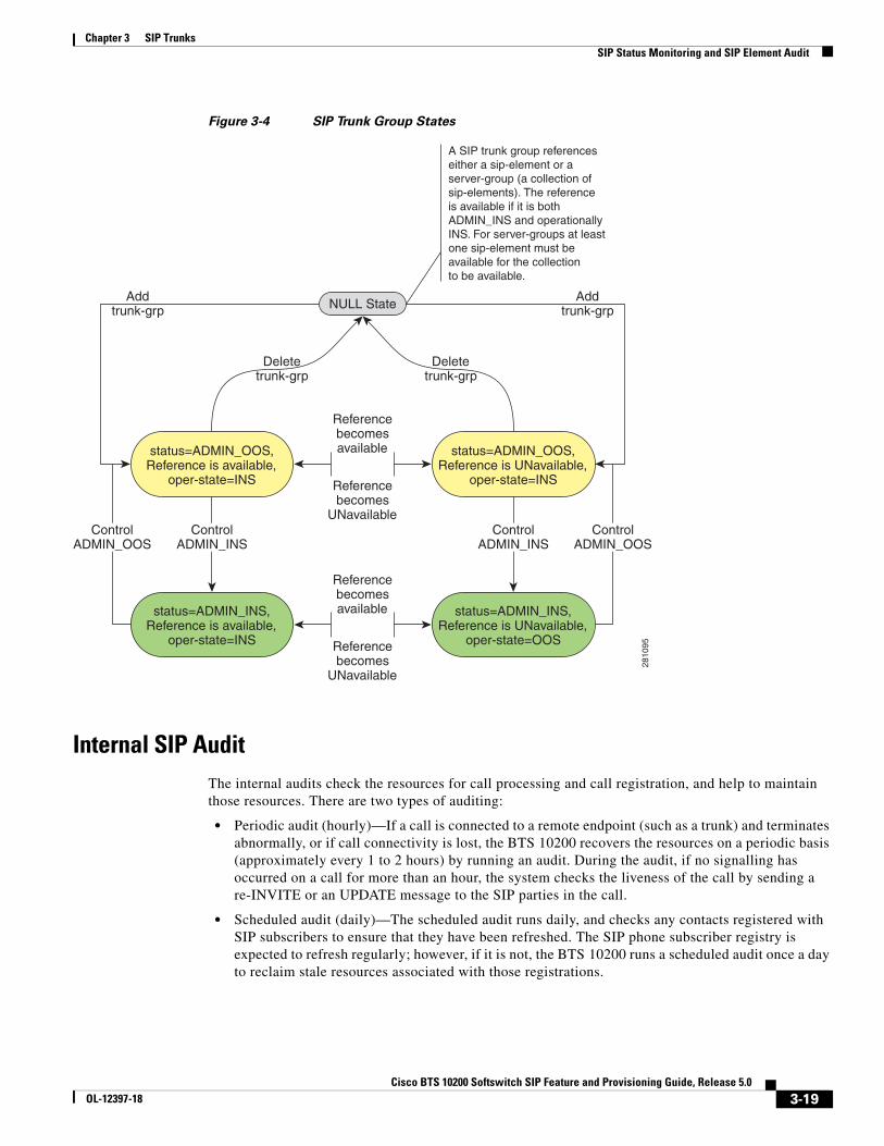
Release 5.0 In version OL-12397-15, the SIP Element State Diagram and the “SIP Trunk Group States” section on page 18 was added in the SIP Trunks chapter.
Release 5.0 In version OL-12397-14, the procedure to provision the ANI screening on incoming calls were added in the “ANI Screening on Incoming Calls” section on page 41.
Release 5.0 In version OL-12397-13, the following changes were made:
• The procedure for provisioning SIP subscribers was transferred to the Cisco BTS 10200 Softswitch Provisioning Guide. See “Provisioning a SIP Subscriber” section on page 2-2.
Release 5.0 In version OL-12397-12, the following changes were made:
• A list of IETF RFC publication references was added in the “General SIP Overview” section on page 1-1.
Release 5.0 In version OL-12397-11, the following changes were made:
• SIP trigger information was updated in the “SIP Triggers” section on page 3-22.
• References to cluster routing and CMS-to-MGC routing were added in Chapter 3, “SIP Trunks.”
• Telephony features were moved to Chapter 2, “SIP Subscribers.”
• The “Configuring the HTTP-FS, MBA, GUI-FS, and SIP Phone Services” section was deleted.
• Information on SIP voice-mail features was moved to Chapter 3, “SIP Trunks.”
• Information on SIP server groups was moved to Chapter 3, “SIP Trunks.”
• Information was added for the following features—Automatic DNS Monitoring and Congestion Control, page 4-13 and Automatic Fault Monitoring and Self-Healing, page 4-13.
• Several other technical clarifications were made (marked with change bars).
In version OL-12397-10, the following changes were made:
• Editorial clarifications were incorporated throughout the document, and some sections were reorganized.
• Chapter 4, “SIP System Features,” was expanded to include information on timers and other SIP system-wide features.
• A section on SIP Server Groups was added.
In version OL-12397-09, a section was added to describe the implementation of the SIP Content-Length header. See the “Message Handling Based On Content-Length Header” section on page 4-12.
In version OL-12397-08, several cross-references (links) were corrected or updated.
In version OL-12397-07, the following changes were made:
• Information regarding the use of vertical service codes (VSCs) was added in the “Vertical Service Code Features” section on page 2-23.
In version OL-12397-06, the following changes were made:
• A description of the SIA process restart capability was added in the “Automatic Fault Monitoring and Self-Healing” section on page 4-13.
In version OL-12397-05, the following changes were made:
• Information was added to clarify that the BTS 10200 validates the hostname of the ReqUri of every received request against the list of names provisioned in the Serving-Domain-Name table. See the “SIP User Authentication” section on page 2-9.
• A statement was added to the description of the Do Not Disturb (DND) feature to note that the reminder ring is not provided to SIP endpoints. See the “Comparison of SIP-Based Features and MGCP-Based Features” section on page 2-13.
• (Release 5.0, Maintenance Release 1) Information was added regarding the contents of the Diversion headers and presentation values. See the “Diversion Indication for SIP Subscribers” section on page 2-12 and the “Diversion Indication for SIP Trunks” section on page 3-26.
Release 5.0, continued
In version OL-12397-04, the following changes were made:
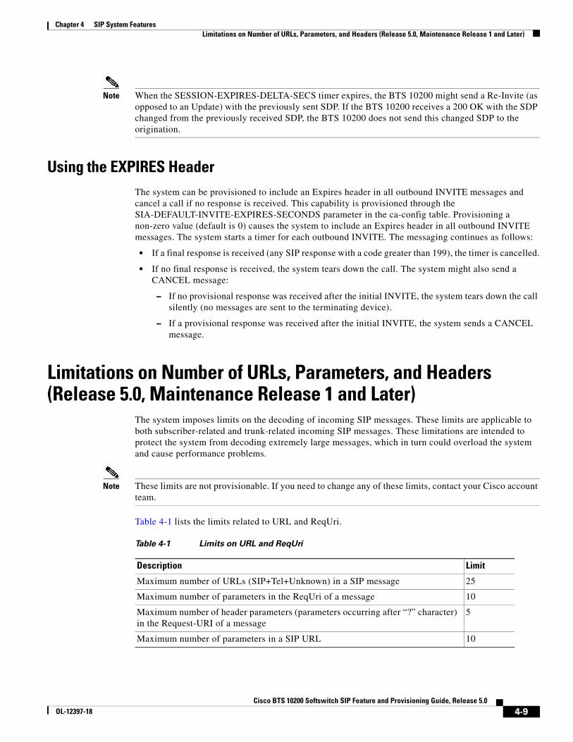
• (Release 5.0, Maintenance Release 1 and later) Information was added regarding the number of parameters in headers. See the “Limitations on Number of URLs, Parameters, and Headers (Release 5.0, Maintenance Release 1 and Later)” section on page 4-9.
In version OL-12397-03, the following changes were made:
• The procedures for installing the HTTP Feature Server (HTTP-FS) and Mini-Browser Adapter (MBA) were clarified. See the “Configuring the HTTP-FS, MBA, GUI-FS, and SIP Phone Services” section on page 2-13.
• A correction was made to the add-serving domain command (auth_reqd=y). See “Provisioning a SIP Subscriber” section on page 2-2.
AudienceThis guide is intended for use by service provider management and system administration personnel who are responsible for installing, provisioning, and maintaining networks that use the Cisco BTS 10200 Softswitch system.
OrganizationThis document is organized as follows:
Chapter 1, “SIP Network Overview”
Chapter 2, “SIP Subscribers”
Chapter 3, “SIP Trunks”
Chapter 4, “SIP System Features”
ConventionsNotes, cautions, and tips are used throughout the document where applicable.
Note Means reader take note. Notes contain helpful suggestions or references to material not covered in the manual.
Tip Means the following information will help you solve a problem. The tips information might not be troubleshooting or even an action, but could be useful information or information that might save time.
Caution Means reader be careful. In this situation, you might do something that could result in equipment damage or loss of data.
Release 5.0 In version OL-12397-02, the following changes were made:
• Clarification was added regarding changes to DSCP parameters in the ca-config table; changes provisioned to these parameters do not take effect until the CA platform restarts or switches over (Chapter 2, “SIP Subscribers” and Chapter 3, “SIP Trunks”).
• The limitation on attended transfer was lifted in the “Call Transfer (Blind and Attended) with REFER” section on page 2-31. Attended transfer can occur on independently placed SIP subscriber calls.
• Wording and formatting improvements were made to the “SIP Call Transfer with REFER and SIP INVITE with Replaces” section on page 3-44.
Obtaining Documentation, Obtaining Support, and Security Guidelines
For information on obtaining documentation, obtaining support, providing documentation feedback, security guidelines, and also recommended aliases and general Cisco documents, see the monthly What’s New in Cisco Product Documentation, which also lists all new and revised Cisco technical documentation, at:
This guide describes the Session Initiation Protocol (SIP) signaling features supported in Release 5.0 of the Cisco BTS 10200 Softswitch, and explains how to provision them.
Note In this document, the term “SIP devices” includes SIP phones and softclients that act as a SIP user agent (UA) to originate and terminate calls for an address of record (AOR) identity.
This chapter contains an overview of the SIP network and includes the following sections:
• General SIP Overview, page 1-1
• SIP Functions Performed by the BTS 10200, page 1-2
General SIP OverviewThe SIP support features are built on the existing BTS 10200 software and hardware platform. The BTS 10200 includes a Call Agent (CA), Feature Server (FS), Element Management System (EMS), and Bulk Data Management System (BDMS). In this book, use of the term “BTS 10200” indicates the Call Agent unless otherwise specified.
SIP support for subscriber features is provided by the Call Agent and the POTS Feature Server.
The BTS 10200 uses SIP and SIP for telephones (SIP-T) signaling to communicate with other SIP-based network elements. The implementation is based upon the evolving industry standards for SIP, including IETF document RFC 3261, SIP: Session Initiation Protocol. The BTS 10200 supports both SIP trunks and SIP-based subscriber lines (SIP devices), and provides the following SIP-related functions:
• Protocol conversion between SIP and several other protocols, including SS7, PRI, ISDN, H.323, MGCP, and CAS.
• Tandem back-to-back user agent for direct SIP-to-SIP calls (trunk to trunk, phone to phone, and trunk to/from phone), and SIP-to-SIP-T calls.
• SS7 bridging between softswitches using SIP-T methods.
• Native support of SIP endpoints such as SIP phones, including authentication and registration management. (For example, the BTS 10200 maintains the current location of SIP subscribers.)
1-1ch SIP Feature and Provisioning Guide, Release 5.0
Chapter 1 SIP Network OverviewSIP Functions Performed by the BTS 10200
The BTS 10200 provides billing data for SIP calls. Specific fields are supported in the call detail records for calls that originate or terminate on a SIP trunk or subscriber. For detailed information on these fields, including billing management and data, refer to the Cisco BTS 10200 Softswitch Billing Interface Guide.
The BTS 10200 SIP implementation is based on the evolving standards in the Internet Engineering Task Force (IETF) Request for Comments (RFC) publications, including the documents in the following list, and may not be fully compliant in all cases. The BTS 10200 is largely compliant with RFC 3261. For the level of compliance with all other RFC publications and drafts referenced in this document, see the specific feature descriptions.
• RFC 2617, HTTP Authentication
• RFC 2976, SIP INFO method
• RFC 3261, SIP: Session Initiation Protocol
• RFC 3262, Reliability of Provisional Responses in the Session Initiation Protocol (SIP)
• RFC 3311, The Session Initiation Protocol (SIP) UPDATE Method
• RFC 3372, Session Initiation Protocol for Telephones (SIP-T): Context and Architectures
• RFC 3398, Integrated Services Digital Network (ISDN) User Part (ISUP) to Session Initiation Protocol (SIP) Mapping
• RFC 3515, The Session Initiation Protocol (SIP) Refer Method
• RFC 3891, The Session Initiation Protocol (SIP) Replaces Header
• RFC 3892, The Session Initiation Protocol (SIP) Referred-By Mechanism
• RFC 4028, Session Timers in the Session Initiation Protocol (SIP)
SIP Functions Performed by the BTS 10200The BTS 10200 supports call processing for SIP trunks and phone users. As a result of native SIP subscriber support, SIP subscribers can use features similar to those available to MGCP subscribers.
Note For a comparison of the MGCP and SIP feature support, see the “Comparison of SIP-Based Features and MGCP-Based Features” section on page 2-13.
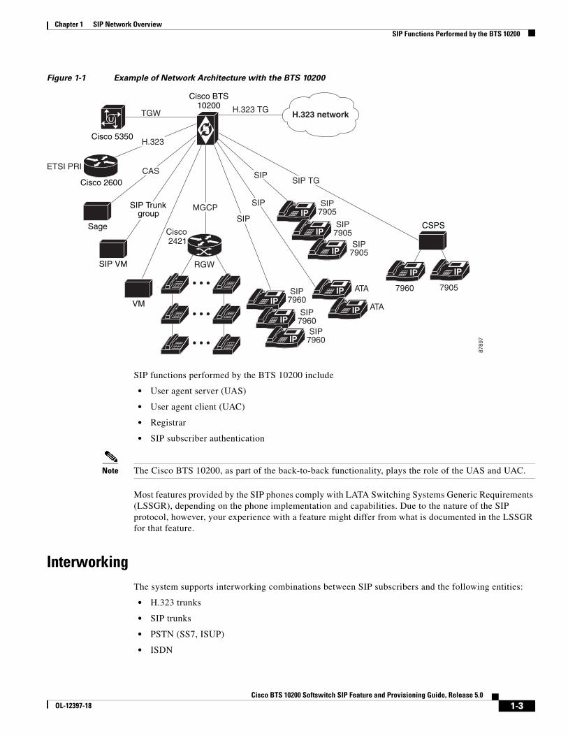
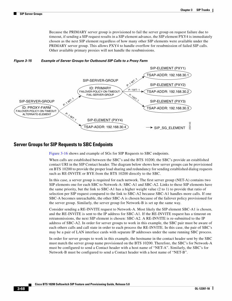
Figure 1-1 shows a network architecture example in which the BTS 10200 provides native support for SIP subscribers and SIP trunks. As shown in this drawing, the BTS 10200 can establish calls between networks with various protocols, including calls between SIP trunks and SIP subscribers. In the SIP network, the BTS 10200 provides Registrar services with SIP user authentication.
Chapter 1 SIP Network OverviewSIP Functions Performed by the BTS 10200
Figure 1-1 Example of Network Architecture with the BTS 10200
SIP functions performed by the BTS 10200 include
• User agent server (UAS)
• User agent client (UAC)
• Registrar
• SIP subscriber authentication
Note The Cisco BTS 10200, as part of the back-to-back functionality, plays the role of the UAS and UAC.
Most features provided by the SIP phones comply with LATA Switching Systems Generic Requirements (LSSGR), depending on the phone implementation and capabilities. Due to the nature of the SIP protocol, however, your experience with a feature might differ from what is documented in the LSSGR for that feature.
InterworkingThe system supports interworking combinations between SIP subscribers and the following entities:
Chapter 1 SIP Network OverviewSIP Functions Performed by the BTS 10200
• MGCP subscribers
For information on SIP cause codes and their relation to standard (Q.850) cause codes, see Appendix H, “SIP Cause Code Mapping” in the Provisioning Guide.
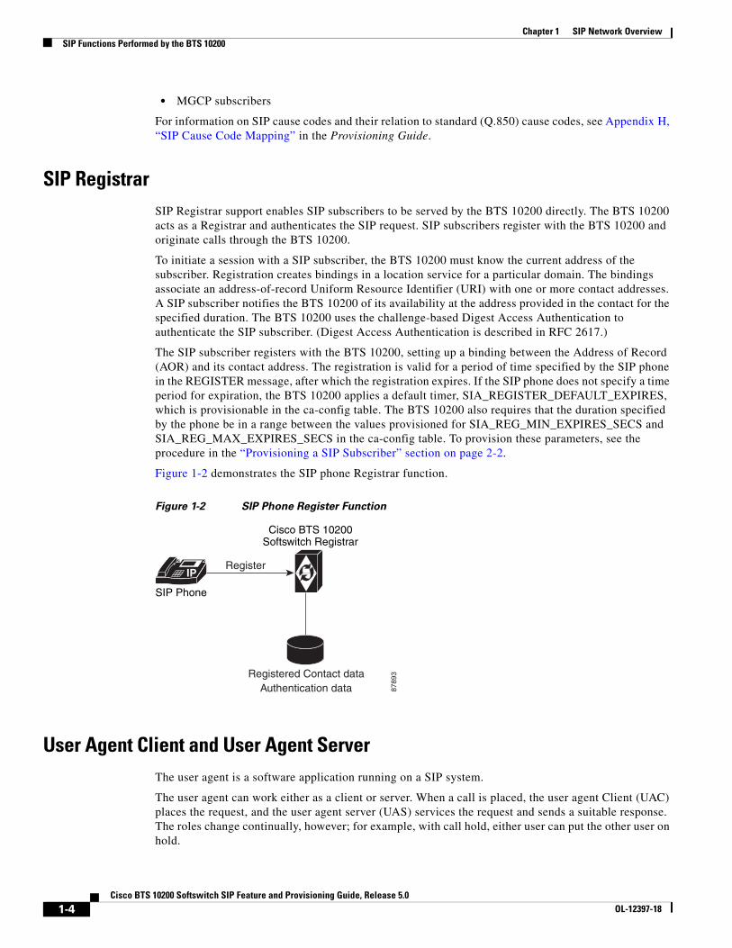
SIP RegistrarSIP Registrar support enables SIP subscribers to be served by the BTS 10200 directly. The BTS 10200 acts as a Registrar and authenticates the SIP request. SIP subscribers register with the BTS 10200 and originate calls through the BTS 10200.
To initiate a session with a SIP subscriber, the BTS 10200 must know the current address of the subscriber. Registration creates bindings in a location service for a particular domain. The bindings associate an address-of-record Uniform Resource Identifier (URI) with one or more contact addresses. A SIP subscriber notifies the BTS 10200 of its availability at the address provided in the contact for the specified duration. The BTS 10200 uses the challenge-based Digest Access Authentication to authenticate the SIP subscriber. (Digest Access Authentication is described in RFC 2617.)
The SIP subscriber registers with the BTS 10200, setting up a binding between the Address of Record (AOR) and its contact address. The registration is valid for a period of time specified by the SIP phone in the REGISTER message, after which the registration expires. If the SIP phone does not specify a time period for expiration, the BTS 10200 applies a default timer, SIA_REGISTER_DEFAULT_EXPIRES, which is provisionable in the ca-config table. The BTS 10200 also requires that the duration specified by the phone be in a range between the values provisioned for SIA_REG_MIN_EXPIRES_SECS and SIA_REG_MAX_EXPIRES_SECS in the ca-config table. To provision these parameters, see the procedure in the “Provisioning a SIP Subscriber” section on page 2-2.
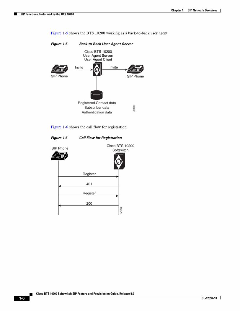
Figure 1-2 demonstrates the SIP phone Registrar function.
Figure 1-2 SIP Phone Register Function
User Agent Client and User Agent ServerThe user agent is a software application running on a SIP system.
The user agent can work either as a client or server. When a call is placed, the user agent Client (UAC) places the request, and the user agent server (UAS) services the request and sends a suitable response. The roles change continually, however; for example, with call hold, either user can put the other user on hold.
Chapter 1 SIP Network OverviewSIP Functions Performed by the BTS 10200
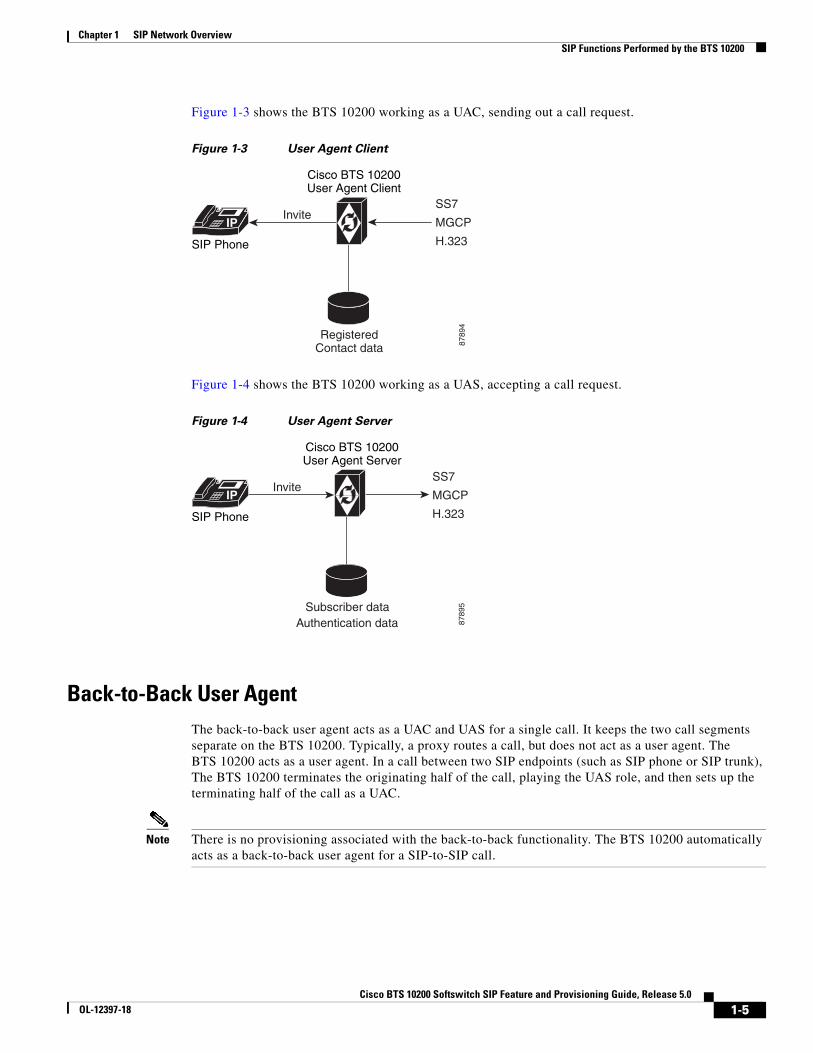
Figure 1-3 shows the BTS 10200 working as a UAC, sending out a call request.
Figure 1-3 User Agent Client
Figure 1-4 shows the BTS 10200 working as a UAS, accepting a call request.
Figure 1-4 User Agent Server
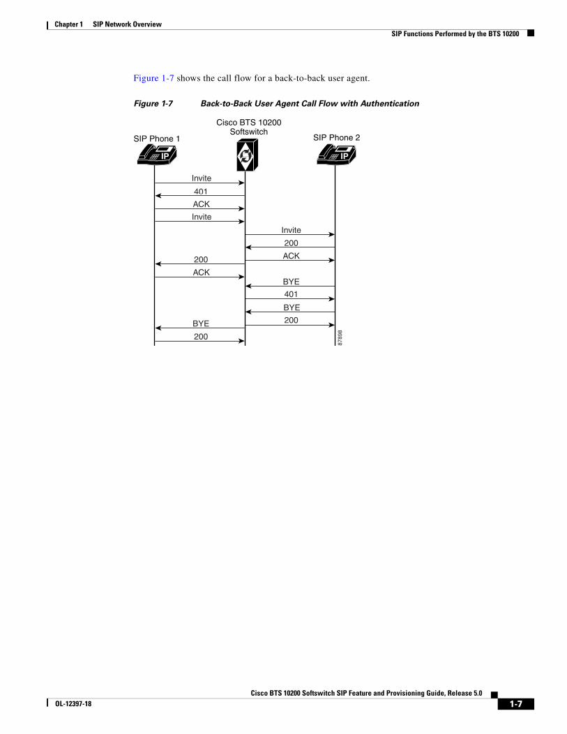
Back-to-Back User AgentThe back-to-back user agent acts as a UAC and UAS for a single call. It keeps the two call segments separate on the BTS 10200. Typically, a proxy routes a call, but does not act as a user agent. The BTS 10200 acts as a user agent. In a call between two SIP endpoints (such as SIP phone or SIP trunk), The BTS 10200 terminates the originating half of the call, playing the UAS role, and then sets up the terminating half of the call as a UAC.
Note There is no provisioning associated with the back-to-back functionality. The BTS 10200 automatically acts as a back-to-back user agent for a SIP-to-SIP call.
The Cisco BTS 10200 Softswitch supports SIP subscribers on SIP phones that are compliant with RFC 3261 or RFC 2543. This section describes the support for SIP subscribers and how to provision SIP subscriber features.
In this document
• SIP subscriber means a SIP phone that is registered directly to the BTS 10200 and for which the BTS 10200 maintains subscriber information.
• SIP ANI-based subscriber means a SIP phone that communicates with the BTS 10200 over a SIP trunk.
Note For quick-reference tables listing the subscriber features, see the “Comparison of SIP-Based Features and MGCP-Based Features” section on page 2-13.
This section covers the following topics:
• SIP Phone Initialization, page 2-2
• Provisioning a SIP Subscriber, page 2-2
• SIP Registration and Security, page 2-2
• SIP User Authentication, page 2-9
• SIP Subscriber Calls, page 2-10
• Provisioning Session Timers for SIP Subscribers, page 2-11
• SIP Timer Values for SIP Subscribers, page 2-11
• Diversion Indication for SIP Subscribers, page 2-12
• Comparison of SIP-Based Features and MGCP-Based Features, page 2-13
2-1ch SIP Feature and Provisioning Guide, Release 5.0
Chapter 2 SIP SubscribersSIP Phone Initialization
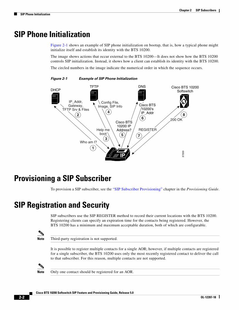
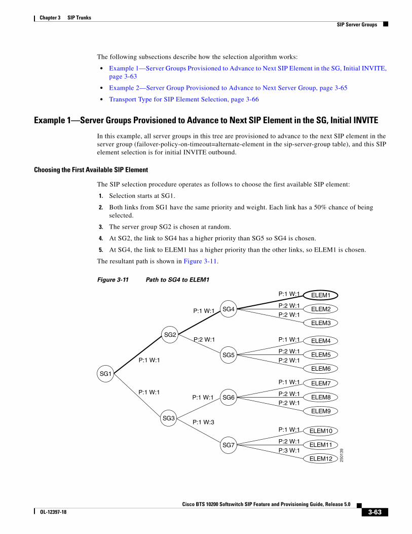
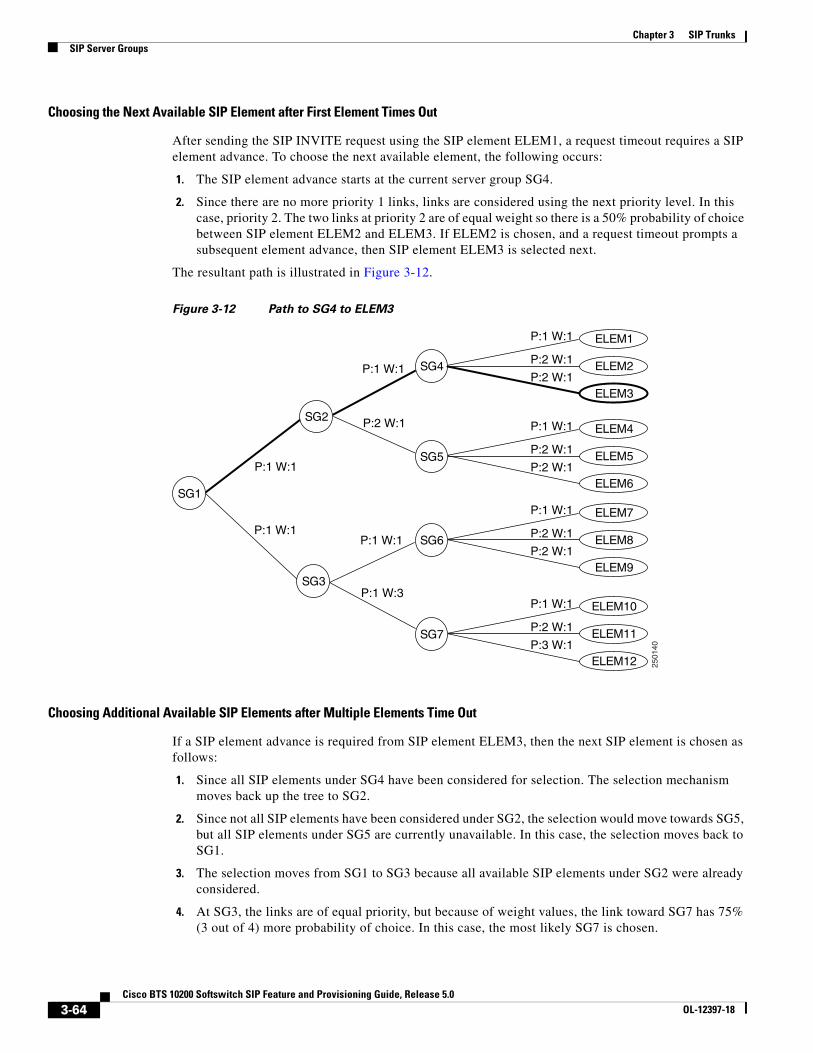
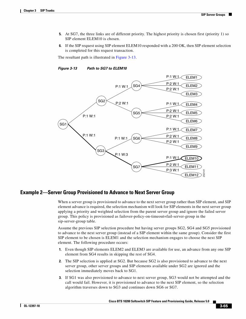
SIP Phone InitializationFigure 2-1 shows an example of SIP phone initialization on bootup, that is, how a typical phone might initialize itself and establish its identity with the BTS 10200.
The image shows actions that occur external to the BTS 10200—It does not show how the BTS 10200 controls SIP initialization. Instead, it shows how a client can establish its identity with the BTS 10200.
The circled numbers in the image indicate the numerical order in which the sequence occurs.
Figure 2-1 Example of SIP Phone Initialization
Provisioning a SIP SubscriberTo provision a SIP subscriber, see the “SIP Subscriber Provisioning” chapter in the Provisioning Guide.
SIP Registration and SecuritySIP subscribers use the SIP REGISTER method to record their current locations with the BTS 10200. Registering clients can specify an expiration time for the contacts being registered. However, the BTS 10200 has a minimum and maximum acceptable duration, both of which are configurable.
Note Third-party registration is not supported.
It is possible to register multiple contacts for a single AOR; however, if multiple contacts are registered for a single subscriber, the BTS 10200 uses only the most recently registered contact to deliver the call to that subscriber. For this reason, multiple contacts are not supported.
Note Only one contact should be registered for an AOR.
Chapter 2 SIP SubscribersSIP Registration and Security
When a SIP user attempts to register or set up a call, the BTS 10200 challenges the SIP subscriber based on provisioning in the Serving Domain Name table. If the Serving Domain Name table indicates that authentication is required, the BTS 10200 challenges the SIP request (Register/INVITE) according to the authentication procedures specified in the SIP Protocol RFC 3261. If the BTS 10200 receives valid credentials, the authenticated AOR from the User Authorization table identifies the subscriber based on the Address of Record to Subscriber table. (For specific provisioning parameters, see the applicable tables in the Cisco BTS 10200 Softswitch CLI Database.)
Registration creates bindings in the BTS 10200 that associate an AOR with one or more contact addresses.
The registration data is replicated on the standby BTS 10200. The BTS 10200 imposes a minimum registration interval as a provisionable value. If the expiration duration of the incoming registration request is lower than the provisioned minimum, a 423 (Interval Too Brief) response is sent to the registering SIP endpoint.
The BTS 10200 generates a warning event when a request from a client fails authentication. This can indicate a provisioning error or an attempt by an unauthorized client to communicate with the BTS 10200.
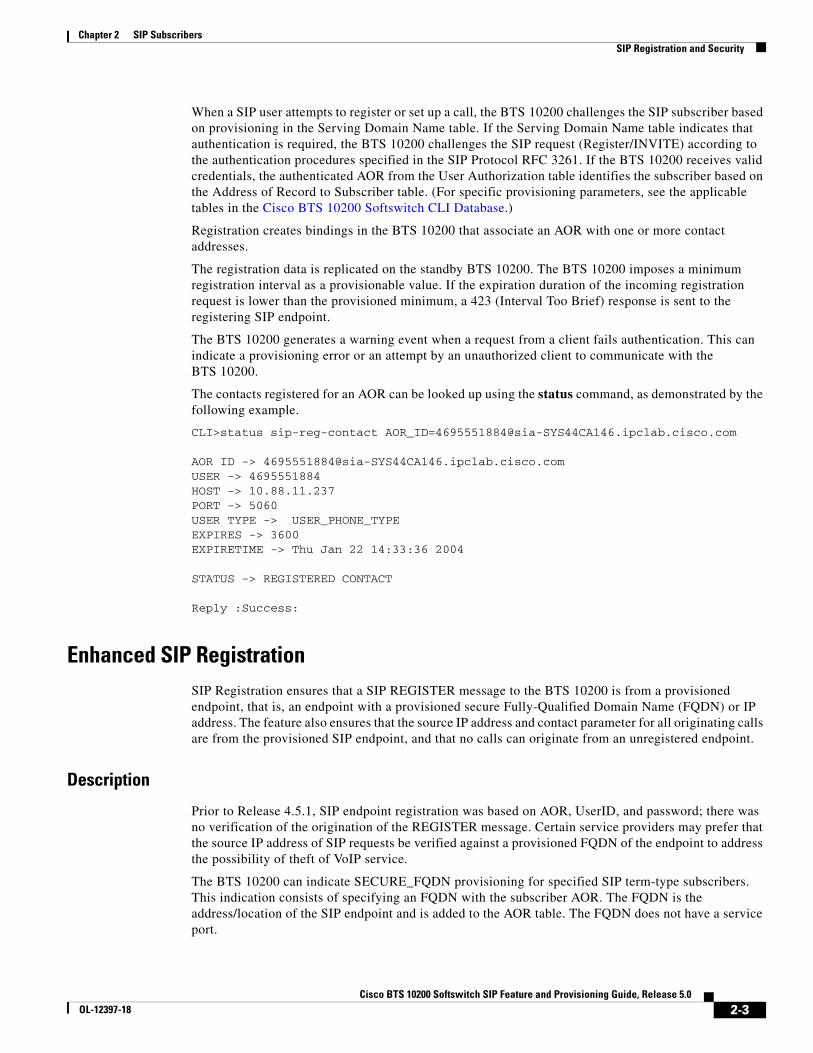
The contacts registered for an AOR can be looked up using the status command, as demonstrated by the following example.
AOR ID -> [email protected] -> 4695551884HOST -> 10.88.11.237PORT -> 5060USER TYPE -> USER_PHONE_TYPEEXPIRES -> 3600EXPIRETIME -> Thu Jan 22 14:33:36 2004
STATUS -> REGISTERED CONTACT
Reply :Success:
Enhanced SIP RegistrationSIP Registration ensures that a SIP REGISTER message to the BTS 10200 is from a provisioned endpoint, that is, an endpoint with a provisioned secure Fully-Qualified Domain Name (FQDN) or IP address. The feature also ensures that the source IP address and contact parameter for all originating calls are from the provisioned SIP endpoint, and that no calls can originate from an unregistered endpoint.
Description
Prior to Release 4.5.1, SIP endpoint registration was based on AOR, UserID, and password; there was no verification of the origination of the REGISTER message. Certain service providers may prefer that the source IP address of SIP requests be verified against a provisioned FQDN of the endpoint to address the possibility of theft of VoIP service.
The BTS 10200 can indicate SECURE_FQDN provisioning for specified SIP term-type subscribers. This indication consists of specifying an FQDN with the subscriber AOR. The FQDN is the address/location of the SIP endpoint and is added to the AOR table. The FQDN does not have a service port.
Chapter 2 SIP SubscribersSIP Registration and Security
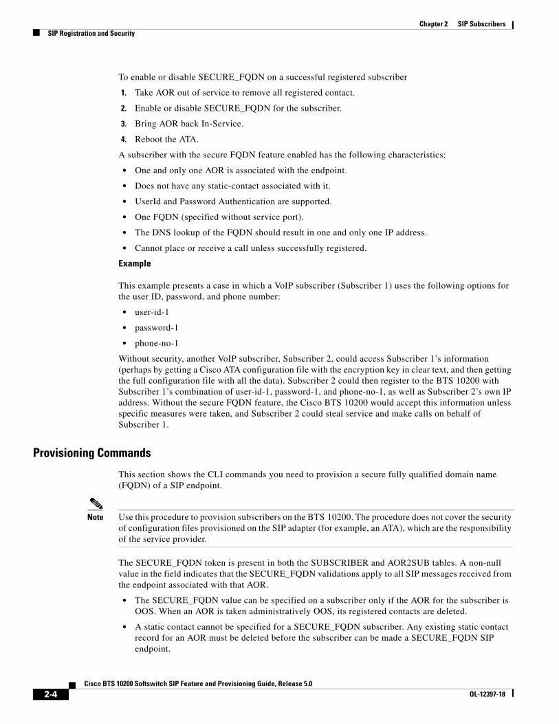
To enable or disable SECURE_FQDN on a successful registered subscriber
1. Take AOR out of service to remove all registered contact.
2. Enable or disable SECURE_FQDN for the subscriber.
3. Bring AOR back In-Service.
4. Reboot the ATA.
A subscriber with the secure FQDN feature enabled has the following characteristics:
• One and only one AOR is associated with the endpoint.
• Does not have any static-contact associated with it.
• UserId and Password Authentication are supported.
• One FQDN (specified without service port).
• The DNS lookup of the FQDN should result in one and only one IP address.
• Cannot place or receive a call unless successfully registered.
Example
This example presents a case in which a VoIP subscriber (Subscriber 1) uses the following options for the user ID, password, and phone number:
• user-id-1
• password-1
• phone-no-1
Without security, another VoIP subscriber, Subscriber 2, could access Subscriber 1’s information (perhaps by getting a Cisco ATA configuration file with the encryption key in clear text, and then getting the full configuration file with all the data). Subscriber 2 could then register to the BTS 10200 with Subscriber 1’s combination of user-id-1, password-1, and phone-no-1, as well as Subscriber 2’s own IP address. Without the secure FQDN feature, the Cisco BTS 10200 would accept this information unless specific measures were taken, and Subscriber 2 could steal service and make calls on behalf of Subscriber 1.
Provisioning Commands
This section shows the CLI commands you need to provision a secure fully qualified domain name (FQDN) of a SIP endpoint.
Note Use this procedure to provision subscribers on the BTS 10200. The procedure does not cover the security of configuration files provisioned on the SIP adapter (for example, an ATA), which are the responsibility of the service provider.
The SECURE_FQDN token is present in both the SUBSCRIBER and AOR2SUB tables. A non-null value in the field indicates that the SECURE_FQDN validations apply to all SIP messages received from the endpoint associated with that AOR.
• The SECURE_FQDN value can be specified on a subscriber only if the AOR for the subscriber is OOS. When an AOR is taken administratively OOS, its registered contacts are deleted.
• A static contact cannot be specified for a SECURE_FQDN subscriber. Any existing static contact record for an AOR must be deleted before the subscriber can be made a SECURE_FQDN SIP endpoint.
Chapter 2 SIP SubscribersSIP Registration and Security
• The SECURE_FQDN in the AOR2SUB table is stored both in the ORACLE database and the shared memory.
AOR2SUB records cannot be added or deleted directly. To add AOR2SUB records, you must specify specify the AOR ID on a subscriber record.
Provision a New SIP Subscriber
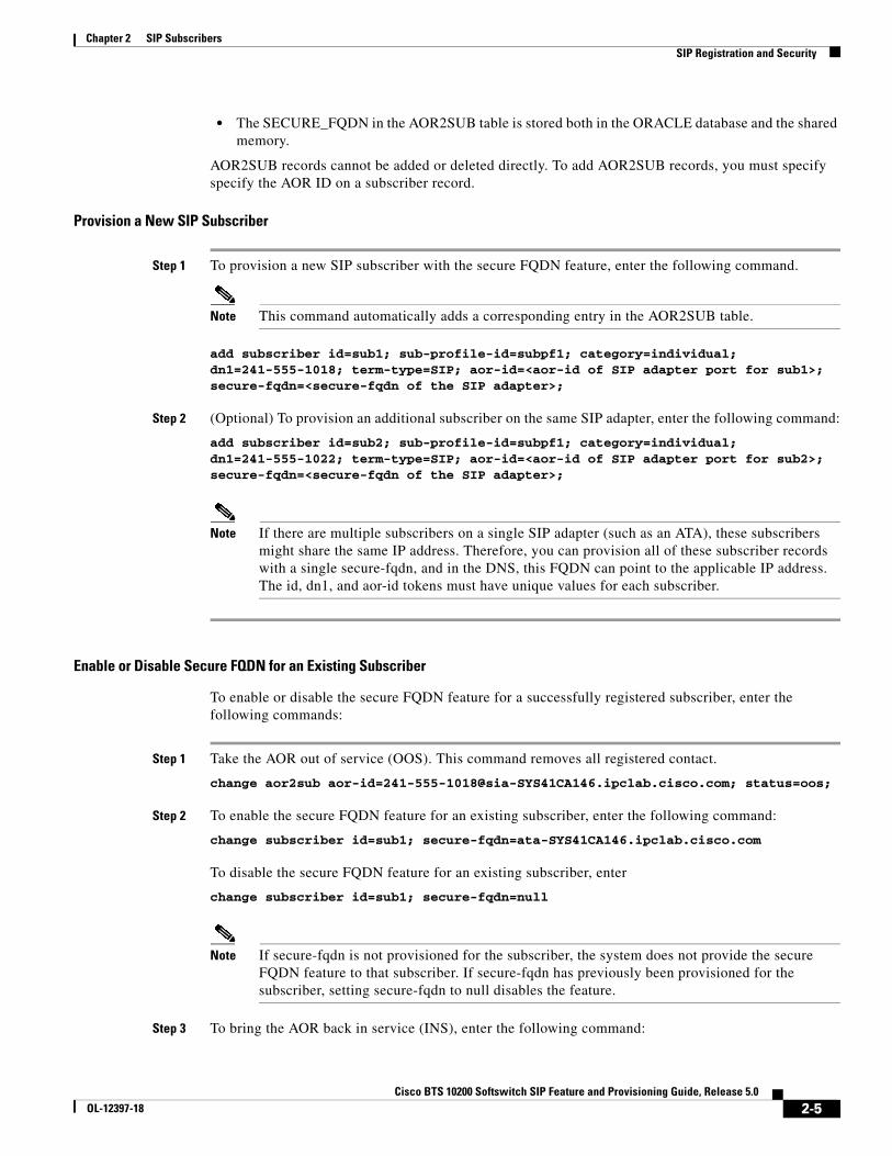
Step 1 To provision a new SIP subscriber with the secure FQDN feature, enter the following command.
Note This command automatically adds a corresponding entry in the AOR2SUB table.
add subscriber id=sub1; sub-profile-id=subpf1; category=individual; dn1=241-555-1018; term-type=SIP; aor-id=<aor-id of SIP adapter port for sub1>; secure-fqdn=<secure-fqdn of the SIP adapter>;
Step 2 (Optional) To provision an additional subscriber on the same SIP adapter, enter the following command:
add subscriber id=sub2; sub-profile-id=subpf1; category=individual; dn1=241-555-1022; term-type=SIP; aor-id=<aor-id of SIP adapter port for sub2>; secure-fqdn=<secure-fqdn of the SIP adapter>;
Note If there are multiple subscribers on a single SIP adapter (such as an ATA), these subscribers might share the same IP address. Therefore, you can provision all of these subscriber records with a single secure-fqdn, and in the DNS, this FQDN can point to the applicable IP address. The id, dn1, and aor-id tokens must have unique values for each subscriber.
Enable or Disable Secure FQDN for an Existing Subscriber
To enable or disable the secure FQDN feature for a successfully registered subscriber, enter the following commands:
Step 1 Take the AOR out of service (OOS). This command removes all registered contact.
To disable the secure FQDN feature for an existing subscriber, enter
change subscriber id=sub1; secure-fqdn=null
Note If secure-fqdn is not provisioned for the subscriber, the system does not provide the secure FQDN feature to that subscriber. If secure-fqdn has previously been provisioned for the subscriber, setting secure-fqdn to null disables the feature.
Step 3 To bring the AOR back in service (INS), enter the following command:
Step 4 Reboot the adapter device (such as ATA) for this subscriber.
OperationsThe system performs the following checks. If any of the following conditions are not met, the request is rejected, and an alarm is generated.
No Calls to or from an Unregistered Secure-Provision SIP Endpoint
An unregistered secure-provision SIP endpoint cannot originate or receive calls.
Third-Party Registrations for Secure FQDN Endpoint Not Allowed
Third-party registrations for secure FQDN endpoints are not allowed.
Cisco BTS 10200 Challenges Registration
On receiving a REGISTER message from a secure-provision SIP endpoint, the BTS 10200 challenges the registration, asking for authentication. Verification of the resend REGISTER message with UserId and Password is as follows, after the UserId and Password are authenticated:
• Ensure that there is only one contact in the contact header.
• Ensure that the source IP address of the REGISTER message is the same IP address of the provisioned FQDN for that endpoint.
• Ensure that the IP address or the FQDN of the contact is the same as the provisioned FQDN for that endpoint.
If any of these conditions are not met, registration is rejected and a security event and alarm is generated, indicating that the source of the registration is illegal.
The contact address can verify all subsequent SIP request source IP address of the request from the endpoint until the registration expired or is deregistered.
Registration Expires
If the registration expires or the end point de-registers, the registration process in the “Cisco BTS 10200 Challenges Registration” section on page 2-6 occurs before any new calls are accepted.
Call Originates From or Terminates to a Secure-Provision SIP Endpoint
When a call originates from or terminates to a secure-provision SIP endpoint
1. The system authenticates the user ID and password on all messages requiring authentication.
2. If the Contact header is available, the system ensures that only one contact is present, and that it has the same IP address or FDQN of the provisioned endpoint.
3. All messages sent by the endpoint and the source IP address of the message must be the same as the internal cache contact address (for example, the cache contact address is the contact obtained during registration).
4. Response from an endpoint that has a contact header must conform to the second item in this list.
Chapter 2 SIP SubscribersSIP Registration and Security
Call Processing
The SIP application in the BTS 10200 implements the secure provisioning feature for all incoming SIP messages (requests and responses) from SIP endpoints.
When a SIP request message is received from a SIP endpoint and Auth_Rqed=Y for the serving domain, the request is challenged. When the request is resubmitted with credentials, the AOR of the authenticated SIP endpoint is used to perform the SECURE_FQDN validation, provided a SECURE_FQDN value is provisioned in the AOR2SUB record. If Auth_Reqd=N, the SECURE_FQDN validation is performed without the request being challenged.
Validation
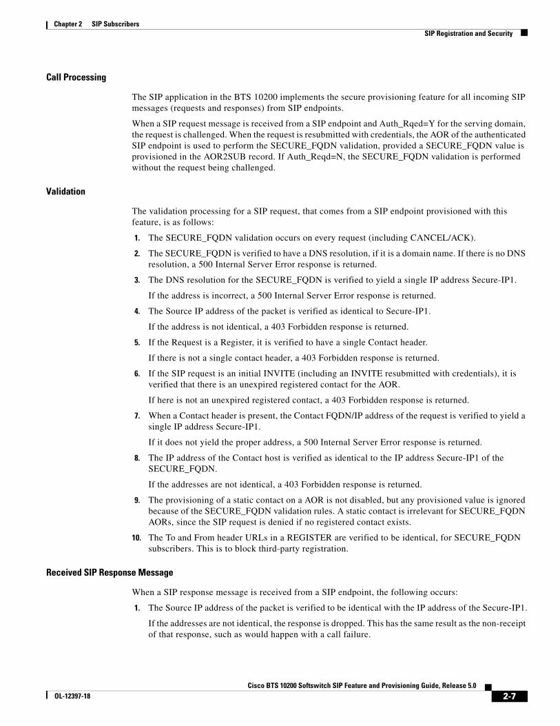
The validation processing for a SIP request, that comes from a SIP endpoint provisioned with this feature, is as follows:
1. The SECURE_FQDN validation occurs on every request (including CANCEL/ACK).
2. The SECURE_FQDN is verified to have a DNS resolution, if it is a domain name. If there is no DNS resolution, a 500 Internal Server Error response is returned.
3. The DNS resolution for the SECURE_FQDN is verified to yield a single IP address Secure-IP1.
If the address is incorrect, a 500 Internal Server Error response is returned.
4. The Source IP address of the packet is verified as identical to Secure-IP1.
If the address is not identical, a 403 Forbidden response is returned.
5. If the Request is a Register, it is verified to have a single Contact header.
If there is not a single contact header, a 403 Forbidden response is returned.
6. If the SIP request is an initial INVITE (including an INVITE resubmitted with credentials), it is verified that there is an unexpired registered contact for the AOR.
If here is not an unexpired registered contact, a 403 Forbidden response is returned.
7. When a Contact header is present, the Contact FQDN/IP address of the request is verified to yield a single IP address Secure-IP1.
If it does not yield the proper address, a 500 Internal Server Error response is returned.
8. The IP address of the Contact host is verified as identical to the IP address Secure-IP1 of the SECURE_FQDN.
If the addresses are not identical, a 403 Forbidden response is returned.
9. The provisioning of a static contact on a AOR is not disabled, but any provisioned value is ignored because of the SECURE_FQDN validation rules. A static contact is irrelevant for SECURE_FQDN AORs, since the SIP request is denied if no registered contact exists.
10. The To and From header URLs in a REGISTER are verified to be identical, for SECURE_FQDN subscribers. This is to block third-party registration.
Received SIP Response Message
When a SIP response message is received from a SIP endpoint, the following occurs:
1. The Source IP address of the packet is verified to be identical with the IP address of the Secure-IP1.
If the addresses are not identical, the response is dropped. This has the same result as the non-receipt of that response, such as would happen with a call failure.
Chapter 2 SIP SubscribersSIP Registration and Security
2. When a Contact header is present on a reliable 1xx or 2xx response, the Contact FQDN/IP address of the response is verified to resolve to the Secure-IP1.
If the address does not resolve properly, the response is dropped. This has the same result as the non-receipt of that response, such as would happen with a call failure.
3. The response for a BYE sent by Cisco BTS 10200 is not validated. This is the least likely point in a call for theft.
Rules for Sending a SIP INVITE Message from the BTS 10200
When a SIP INVITE message is sent to a SIP endpoint, the following occurs:
1. The INVITE is sent to the registered contact of the endpoint. If there is no registered contact or if the registered contact has expired, the INVITE is not sent and the call is declined.
2. Any static contact provisioned for the subscriber is ignored.
Note Provisioning of static contact is not allowed for secure SIP endpoints; therefore, this is merely due diligence.
Validation of ACK Request
When a SIP ACK message is received from a SIP endpoint, the following occurs:
1. The ACK for a 200-class response is validated like any other SIP request.
2. The ACK for a failure response (3xx or higher) is not validated.
MeasurementsThe following TMM counters are supported for secure FQDN violations:
• A SIA-SECURE_FQDN-VIOLATION-REQ counter is incremented when a SIP request fails the validation for secure SIP endpoints.
• A SIA-SECURE_FQDN-VIOLATION-RESP counter is incremented when a SIP response fails the validation for secure SIP endpoints.
Note For a full list of measurements, see the Cisco BTS 10200 Softswitch Operations and Maintenance Guide.
Events and AlarmsA Warning event is raised when a SIP request or response fails the validation for secure SIP endpoints. The alarm has the following attributes:
SIP User AuthenticationThe BTS 10200 can act as an authentication server. Authentication is enabled on the serving domain through provisioning.
Whenever a SIP request is received from a SIP subscriber, the request is authenticated to ensure it is indeed from an identified user. Authentication also enables request authorization, because users may be authorized to perform only specific requests.
The following examples are the functional scenarios in which authentication is required:
1. When a SIP user registers a contact with the BTS 10200 Registrar using a REGISTER request.
2. When a SIP user initiates a call using an INVITE request.
3. When a SIP user sends any request in an ongoing call. Examples include
– Re-negotiation of the call parameters using a re-INVITE
– Terminating the call using a BYE
– Initiating a call transfer using a REFER
4. When a SIP user sends a request outside a dialog. Example: OPTIONS.
The following tables affect authentication for SIP subscribers:
• AOR
• Serving Domain
• Auth-Realm
• User-Auth
See the Cisco BTS 10200 Softswitch CLI Database for more information about the tables.
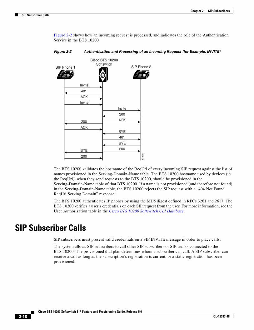
Figure 2-2 shows how an incoming request is processed, and indicates the role of the Authentication Service in the BTS 10200.
Figure 2-2 Authentication and Processing of an Incoming Request (for Example, INVITE)
The BTS 10200 validates the hostname of the ReqUri of every incoming SIP request against the list of names provisioned in the Serving-Domain-Name table. The BTS 10200 hostname used by devices (in the ReqUri), when they send requests to the BTS 10200, should be provisioned in the Serving-Domain-Name table of that BTS 10200. If a name is not provisioned (and therefore not found) in the Serving-Domain-Name table, the BTS 10200 rejects the SIP request with a “404 Not Found ReqUri Serving Domain” response.
The BTS 10200 authenticates IP phones by using the MD5 digest defined in RFCs 3261 and 2617. The BTS 10200 verifies a user’s credentials on each SIP request from the user. For more information, see the User Authorization table in the Cisco BTS 10200 Softswitch CLI Database.
SIP Subscriber CallsSIP subscribers must present valid credentials on a SIP INVITE message in order to place calls.
The system allows SIP subscribers to call other SIP subscribers or SIP trunks connected to the BTS 10200. The provisioned dial plan determines whom a subscriber can call. A SIP subscriber can receive a call as long as the subscription’s registration is current, or a static registration has been provisioned.
Chapter 2 SIP SubscribersProvisioning Session Timers for SIP Subscribers
Provisioning Session Timers for SIP SubscribersThe system uses session timers to periodically refresh SIP sessions during call processing or in-progress calls. You can enable or disable session timers for calls to and from all SIP subscribers on the BTS 10200 through the SUB_SESSION_TIMER_ALLOWED parameter in the ca-config table. They are disabled by default.
Use the commands in this section to provision session timers for SIP subscribers. Session timer defaults for subscribers are defined by internal defaults. They can be adjusted through the commands shown in this section.
Note For a detailed description of session timers, see “SIP Session Timers” section on page 4-7
Step 1 Adjust the session timer values in the sip-timer-profile table.
Note The session duration field value is in seconds with a range of 100 to 7200. The minimum session duration field value is in seconds with a range of 100 to 1800. We recommend a value of at least 1800 for each of these fields.
Note This section describes how to provision SIP timer values for SIP subscribers. For a comprehensive listing of SIP timers, see Chapter 4, “SIP System Features.”
You can customize SIP timers through the sip-timer-profile table. A record in this table can then be configured to apply to all subscribers switch-wide. The system operates with default SIP protocol timer values, as noted in the SIP specification. These default values are adequate for many installations. If customization is required, a sip-timer-profile table can be provisioned and associated with all calls.
Use the following steps to provision the SIP timer values.
Step 1 Adjust the SIP timer values in the sip-timer-profile table if necessary (example shown).
Diversion Indication for SIP SubscribersDiversion indication provides supplemental redirection information to the SIP entity receiving a call. The SIP entity uses this information to identify from whom the call was diverted, and why the call was diverted. It also provides information for each redirection if multiple redirections occurred. This is provided in the form of a SIP Diversion header.
Forwarding information allows applications such as SIP voice-mail servers to access the mailbox of the original called party for proper outgoing greeting and message deposit when a forwarded call is received. Billing systems also use the information to determine the charged party of the call where it is the last forwarding party that is billed.
The BTS 10200 supports the Diversion Indication feature according to the specifications in the IETF document draft-levy-sip-diversion-02.txt. For incoming calls, the BTS 10200 uses the party number information from the top-most and bottom-most diversion headers. The BTS 10200 reads the diversion count across all diversion headers to determine the total diversion count. For outgoing calls, The BTS 10200 sends 0, 1 or 2 diversion headers, depending on the forwarding information of the call.
Diversion header parameter support is limited to the diversion counter and the diversion reason. These two parameters in diversion headers are populated for outgoing calls and interpreted on incoming calls.
For INVITEs sent out by the BTS 10200, the following behavior applies:
• If no diversion information is available, no diversion headers are included.
• If there is an original called party, one diversion header is added to the outgoing INVITE message.
• If there is a last forwarding party, a second diversion header is added on top of the original called party diversion header.
• Each outgoing diversion header is populated with the party number, the diversion reason, and the diversion count.
• For Release 5.0, Maintenance Release 1 and later, privacy parameters are sent and received in the Diversion header.
• For Release 5.0, Maintenance Release 1 and later, If the original called number (OCN) and/or the redirected DN (RDN) are being sent in Diversion headers towards local SIP subscribers, and the presentation value is not allowed, the system applies anonymous to them as follows:
– If an OCN exists, it populates the URL as [email protected] in the To header.
– If a Diversion header is added, it populates the user part of the diversion header with anonymous.
Chapter 2 SIP SubscribersComparison of SIP-Based Features and MGCP-Based Features
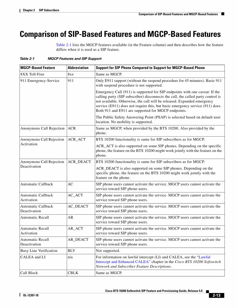
Comparison of SIP-Based Features and MGCP-Based FeaturesTable 2-1 lists the MGCP features available (in the Feature column) and then describes how the feature differs when it is used as a SIP feature.
Table 2-1 MGCP Features and SIP Support
MGCP-Based Feature Abbreviation Support for SIP Phone Compared to Support for MGCP-Based Phone
8XX Toll-Free 8xx Same as MGCP.
911 Emergency-Service 911 Only E911 support (without the suspend procedure for 45 minutes). Basic 911 with suspend procedure is not supported.
Emergency Call (911) is supported for SIP endpoints with one caveat: If the calling party (SIP subscriber) disconnects the call, the called party control is not available. Otherwise, the call will be released. Expanded emergency service (E911) does not require this, but basic emergency service (911) does. Both 911 and E911 are supported for MGCP endpoints.
The Public Safety Answering Point (PSAP) is selected based on default user location. No mobility is supported.
Anonymous Call Rejection ACR Same as MGCP, when provided by the BTS 10200. Also provided by the phone.
Anonymous Call Rejection Activation
ACR_ACT BTS 10200 functionality is same for SIP subscribers as for MGCP.
ACR_ACT is also supported on some SIP phones. Depending on the specific phone, the feature on the BTS 10200 might work jointly with the feature on the phone.
Anonymous Call Rejection Deactivation
ACR_DEACT BTS 10200 functionality is same for SIP subscribers as for MGCP.
ACR_DEACT is also supported on some SIP phones. Depending on the specific phone, the feature on the BTS 10200 might work jointly with the feature on the phone.
Automatic Callback AC SIP phone users cannot activate the service. MGCP users cannot activate the service toward SIP phone users.
Automatic Callback Activation
AC_ACT SIP phone users cannot activate the service. MGCP users cannot activate the service toward SIP phone users.
Automatic Callback Deactivation
AC_DEACT SIP phone users cannot activate the service. MGCP users cannot activate the service toward SIP phone users.
Automatic Recall AR SIP phone users cannot activate the service. MGCP users cannot activate the service toward SIP phone users.
Automatic Recall Activation
AR_ACT SIP phone users cannot activate the service. MGCP users cannot activate the service toward SIP phone users.
Automatic Recall Deactivation
AR_DEACT SIP phone users cannot activate the service. MGCP users cannot activate the service toward SIP phone users.
Busy Line Verification BLV Not supported.
CALEA and LI n/a For information on lawful intercept (LI) and CALEA, see the “Lawful Intercept and Enhanced CALEA” chapter in the Cisco BTS 10200 Softswitch Network and Subscriber Feature Descriptions.
Chapter 2 SIP SubscribersComparison of SIP-Based Features and MGCP-Based Features
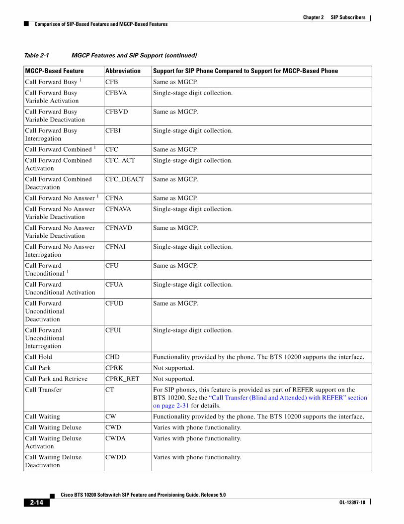
Call Forward Busy 1 CFB Same as MGCP.
Call Forward Busy Variable Activation
CFBVA Single-stage digit collection.
Call Forward Busy Variable Deactivation
CFBVD Same as MGCP.
Call Forward Busy Interrogation
CFBI Single-stage digit collection.
Call Forward Combined 1 CFC Same as MGCP.
Call Forward Combined Activation
CFC_ACT Single-stage digit collection.
Call Forward Combined Deactivation
CFC_DEACT Same as MGCP.
Call Forward No Answer 1 CFNA Same as MGCP.
Call Forward No Answer Variable Deactivation
CFNAVA Single-stage digit collection.
Call Forward No Answer Variable Deactivation
CFNAVD Same as MGCP.
Call Forward No Answer Interrogation
CFNAI Single-stage digit collection.
Call Forward Unconditional 1
CFU Same as MGCP.
Call Forward Unconditional Activation
CFUA Single-stage digit collection.
Call Forward Unconditional Deactivation
CFUD Same as MGCP.
Call Forward Unconditional Interrogation
CFUI Single-stage digit collection.
Call Hold CHD Functionality provided by the phone. The BTS 10200 supports the interface.
Call Park CPRK Not supported.
Call Park and Retrieve CPRK_RET Not supported.
Call Transfer CT For SIP phones, this feature is provided as part of REFER support on the BTS 10200. See the “Call Transfer (Blind and Attended) with REFER” section on page 2-31 for details.
Call Waiting CW Functionality provided by the phone. The BTS 10200 supports the interface.
Call Waiting Deluxe CWD Varies with phone functionality.
Call Waiting Deluxe Activation
CWDA Varies with phone functionality.
Call Waiting Deluxe Deactivation
CWDD Varies with phone functionality.
Table 2-1 MGCP Features and SIP Support (continued)
MGCP-Based Feature Abbreviation Support for SIP Phone Compared to Support for MGCP-Based Phone
Chapter 2 SIP SubscribersComparison of SIP-Based Features and MGCP-Based Features
Call Waiting Deluxe Interrogation
CWDI Varies with phone functionality.
Calling Identity Delivery and Suppression (Delivery) 2
CIDSD Presentation status from the phone, and single-stage digit collection.
Calling Identity Delivery and Suppression (Suppression) 2
CIDSS Presentation status from the phone, and single-stage digit collection.
Calling Identity Delivery on Call Waiting
CIDCW Functionality provided by the phone. Cisco BTS 10200 supports the interface.
Calling Name Delivery 3 CNAM Same as MGCP.
Calling Name Delivery Blocking
CNAB Presentation status from the phone, and single-stage digit collection.
Calling Number Delivery 3 CND The calling party number, if available, is delivered in the From header of the outgoing INVITE from the BTS 10200 to the terminating SIP phone. The number is delivered to the SIP phone even if the CND feature is not provisioned for the subscriber.
Calling Number Delivery Blocking
CNDB Presentation status from the phone, and single-stage digit collection.
Cancel Call Waiting CCW Functionality provided by the phone. Cisco BTS 10200 supports the interface.
Class of Service COS CoS Screening supported, without Auth/Account code collection.
Custom-Dial-Plan CDP Same as MGCP.
Customer Originated Trace COT Same as MGCP.
Directed Call Pickup without Barge-in
DPN Not supported.
Directed Call Pickup with Barge-in
DPU Not supported.
Distinctive Alerting Call Waiting Indication
DACWI This feature is provided to Centrex users only.
Provisioning for SIP does not differ from provisioning for MGCP. However, the delivery method for DACWI is different.
The Centrex administrator provisions a list of DNs that are to receive DACWI tones.
In MGCP, the phone plays the tone specified by the BTS 10200 in the protocol message. In SIP, the tone provisioned for the DN is specified by the BTS 10200 in the Alert-Info header of the INVITE as a file URL. A SIP phone, if capable, interprets this header and plays the specified distinctive ringing or call-waiting tone.
Table 2-1 MGCP Features and SIP Support (continued)
MGCP-Based Feature Abbreviation Support for SIP Phone Compared to Support for MGCP-Based Phone
Chapter 2 SIP SubscribersComparison of SIP-Based Features and MGCP-Based Features
Distinctive Ringing Call Waiting
DRCW Provisioning for SIP does not differ from provisioning for MGCP. However, the delivery method for DRCW is different.
The subscriber provisions a list of DNs to receive DRCW tones.
In MGCP, the phone plays the tone specified by the Cisco BTS 10200 in the protocol message. In SIP, the tone provisioned for the DN is specified by the Cisco BTS 10200 in the Alert-Info header of the INVITE as a file URL. A SIP phone, if capable, can interpret this header and play the specified distinctive ringing or call-waiting tone.
Distinctive Ringing Call Waiting
DRCW_ACT Same as MGCP.
Do Not Disturb DND Same as MGCP, except that the reminder ring cannot be used with SIP devices. For additional information on DND, see the “Do Not Disturb” section on page 2-22.
Do Not Disturb Activation DND_ACT Same as MGCP.
Do Not Disturb Deactivation
DND_DEACT Same as MGCP.
Group Speed Call—1 digit GSC1D Not supported.
Group Speed Call—2 digit GSC2D Not supported.
Hotline HOTLINE Not supported.
Hotline Variable HOTV Not supported.
Hotline Variable Activation HOTVA Not supported.
Hotline Variable Deactivation
HOTVD Not supported.
Hotline Variable Interrogation
HOTVI Not supported.
Incoming Simulated Facility Group
ISFG Same as MGCP.
Local Number Portability LNP Same as MGCP.
Multiline Hunt Group MLHG MLHG is not supported for SIP subscribers.
Multiple Directory Number MDN Provisioning for SIP does not differ from provisioning for MGCP. However, the delivery methods for distinctive -ringing (a distinctive ring tone for each line of the MDN subscriber), and the distinctive tone on call waiting are different.
You provision distinctive ringing and call waiting tones for each DN of the MDN subscriber in the same manner for MGCP and SIP. In MGCP, the phone plays the tone specified by the Cisco BTS 10200 in the protocol message. In SIP, the tone provisioned for the DN is specified by the Cisco BTS 10200 in the Alert-Info header of the INVITE as a file URL. A SIP phone, if capable, can interpret this header and play the specified distinctive ringing or call waiting tone.
Outgoing Call Barring OCB Same as MGCP.
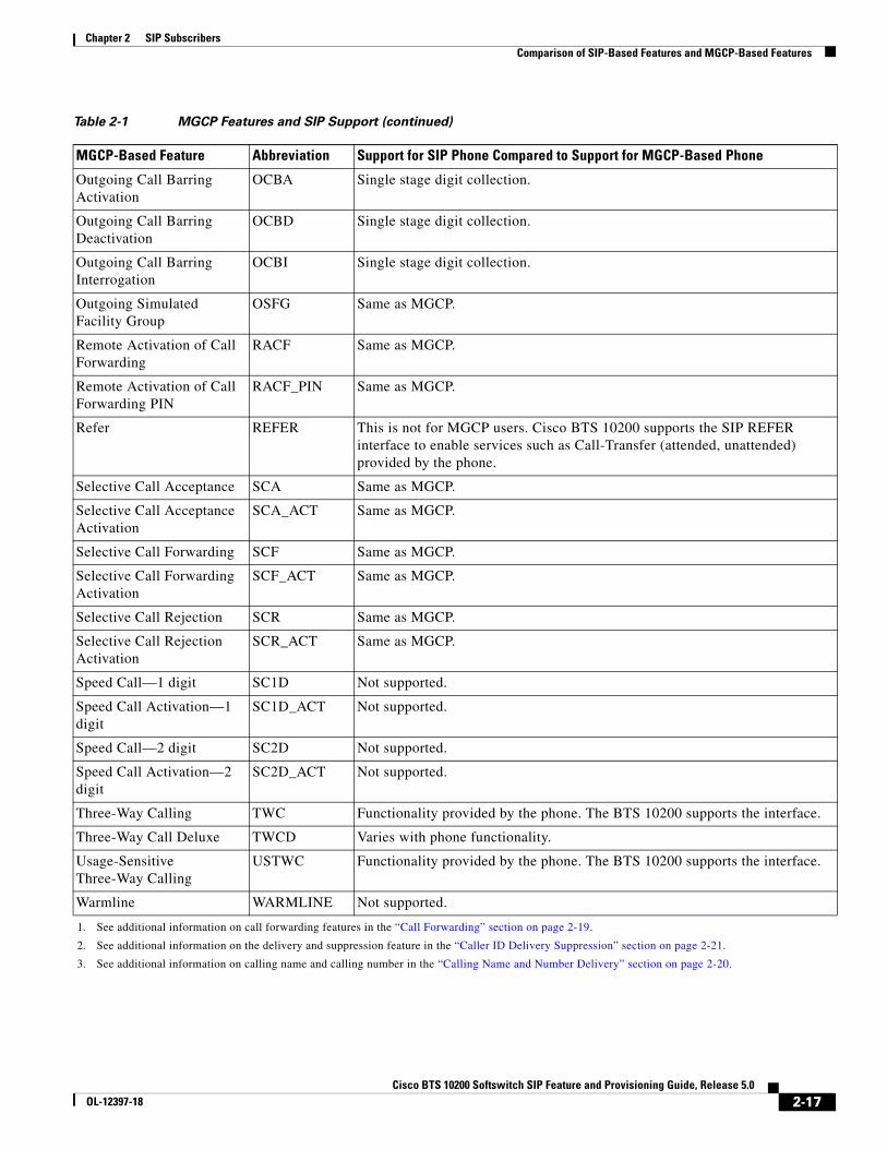
Table 2-1 MGCP Features and SIP Support (continued)
MGCP-Based Feature Abbreviation Support for SIP Phone Compared to Support for MGCP-Based Phone
Chapter 2 SIP SubscribersComparison of SIP-Based Features and MGCP-Based Features
Outgoing Call Barring Activation
OCBA Single stage digit collection.
Outgoing Call Barring Deactivation
OCBD Single stage digit collection.
Outgoing Call Barring Interrogation
OCBI Single stage digit collection.
Outgoing Simulated Facility Group
OSFG Same as MGCP.
Remote Activation of Call Forwarding
RACF Same as MGCP.
Remote Activation of Call Forwarding PIN
RACF_PIN Same as MGCP.
Refer REFER This is not for MGCP users. Cisco BTS 10200 supports the SIP REFER interface to enable services such as Call-Transfer (attended, unattended) provided by the phone.
Selective Call Acceptance SCA Same as MGCP.
Selective Call Acceptance Activation
SCA_ACT Same as MGCP.
Selective Call Forwarding SCF Same as MGCP.
Selective Call Forwarding Activation
SCF_ACT Same as MGCP.
Selective Call Rejection SCR Same as MGCP.
Selective Call Rejection Activation
SCR_ACT Same as MGCP.
Speed Call—1 digit SC1D Not supported.
Speed Call Activation—1 digit
SC1D_ACT Not supported.
Speed Call—2 digit SC2D Not supported.
Speed Call Activation—2 digit
SC2D_ACT Not supported.
Three-Way Calling TWC Functionality provided by the phone. The BTS 10200 supports the interface.
Three-Way Call Deluxe TWCD Varies with phone functionality.
Usage-Sensitive Three-Way Calling
USTWC Functionality provided by the phone. The BTS 10200 supports the interface.
Warmline WARMLINE Not supported.
1. See additional information on call forwarding features in the “Call Forwarding” section on page 2-19.
2. See additional information on the delivery and suppression feature in the “Caller ID Delivery Suppression” section on page 2-21.
3. See additional information on calling name and calling number in the “Calling Name and Number Delivery” section on page 2-20.
Table 2-1 MGCP Features and SIP Support (continued)
MGCP-Based Feature Abbreviation Support for SIP Phone Compared to Support for MGCP-Based Phone
Chapter 2 SIP SubscribersCisco BTS 10200 Softswitch-Based Features
Cisco BTS 10200 Softswitch-Based FeaturesSoftswitch-based features are directly provided by the BTS 10200. SIP phones can provide some features on their own; for information on the features provided by the different SIP phones, see the SIP phone administration guides.
This section describes Softswitch-based features entirely provided by the BTS 10200.
Note BTS 10200 announcements are customizable on a business group basis. If an announcement is not provisioned or cannot be played, a reorder tone is played.
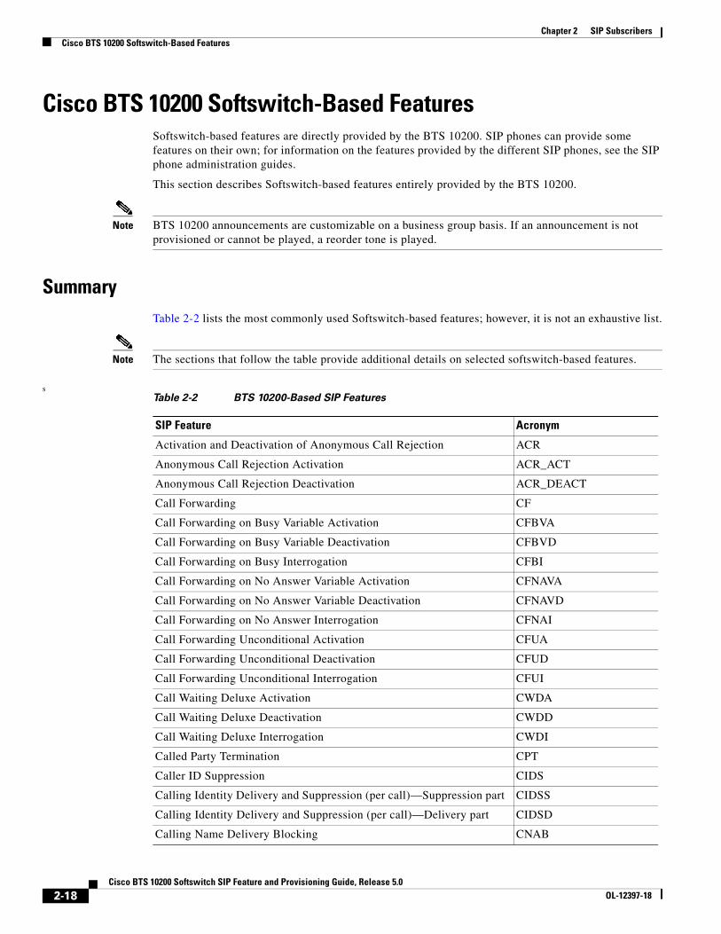
SummaryTable 2-2 lists the most commonly used Softswitch-based features; however, it is not an exhaustive list.
Note The sections that follow the table provide additional details on selected softswitch-based features.
sTable 2-2 BTS 10200-Based SIP Features
SIP Feature Acronym
Activation and Deactivation of Anonymous Call Rejection ACR
Anonymous Call Rejection Activation ACR_ACT
Anonymous Call Rejection Deactivation ACR_DEACT
Call Forwarding CF
Call Forwarding on Busy Variable Activation CFBVA
Call Forwarding on Busy Variable Deactivation CFBVD
Call Forwarding on Busy Interrogation CFBI
Call Forwarding on No Answer Variable Activation CFNAVA
Call Forwarding on No Answer Variable Deactivation CFNAVD
Call Forwarding on No Answer Interrogation CFNAI
Call Forwarding Unconditional Activation CFUA
Call Forwarding Unconditional Deactivation CFUD
Call Forwarding Unconditional Interrogation CFUI
Call Waiting Deluxe Activation CWDA
Call Waiting Deluxe Deactivation CWDD
Call Waiting Deluxe Interrogation CWDI
Called Party Termination CPT
Caller ID Suppression CIDS
Calling Identity Delivery and Suppression (per call)—Suppression part CIDSS
Calling Identity Delivery and Suppression (per call)—Delivery part CIDSD
Chapter 2 SIP SubscribersCisco BTS 10200 Softswitch-Based Features
Call ForwardingThe differences between the feature for SIP and the feature for MGCP are as follows:
• There is no tone provided for SIP users to prompt for forwarding digits. The SIP users enter the forwarding digits immediately after the VSC. This is called single-stage dialing.
• There is no dial tone played after the SIP user successfully activates or deactivates the Forwarding features. The SIP user always hears an announcement (if announcements are provisioned) or a re-order tone.
Call Forwarding Activation and Deactivation
Activation and deactivation of call forwarding features use the vertical service code (VSC), also known as a star code.
With SIP support, the call forwarded to number can be a Centrex extension number (only applicable for business users) or an E.164 number.
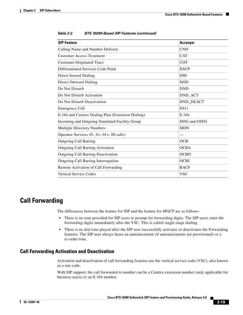
Calling Name and Number Delivery CND
Customer Access Treatment CAT
Customer-Originated Trace COT
Differentiated Services Code Point DSCP
Direct Inward Dialing DID
Direct Outward Dialing DOD
Do Not Disturb DND
Do Not Disturb Activation DND_ACT
Do Not Disturb Deactivation DND_DEACT
Emergency Call E911
E.164 and Centrex Dialing Plan (Extension Dialing) E.164
Incoming and Outgoing Simulated Facility Group ISFG and OSFG
Multiple Directory Numbers MDN
Operator Services (0-, 0+, 01+, 00 calls) —
Outgoing Call Barring OCB
Outgoing Call Barring Activation OCBA
Outgoing Call Barring Deactivation OCBD
Outgoing Call Barring Interrogation OCBI
Remote Activation of Call Forwarding RACF
Vertical Service Codes VSC
Table 2-2 BTS 10200-Based SIP Features (continued)
Chapter 2 SIP SubscribersCisco BTS 10200 Softswitch-Based Features
Note Forwarding to a URL address of record (AOR) is not supported.
SIP subscribers do not hear a final dial tone upon completing activation or deactivation. Instead, an announcement plays for the subscriber, indicating that the status of the forwarding feature is being activated or deactivated. This is irrespective of the Final Stage Dial Tone (FDT) flag (Y/N) provisioned for these features.
Call Forwarding to an E.164 Number or an Extension Number
Activation and deactivation are accomplished using single-stage dialing.
Detailed Provisioning Procedure and Feature Description
Additional information on this feature is provided at the following links.
Calling Name and Number DeliveryCalling number delivery (CND) provides the SIP subscriber endpoint with the calling number of an incoming call. Calling name delivery (CNAM) provides the endpoint with the name of the calling party.
CND
The calling party number, if available, is delivered in the From header of the outgoing INVITE from the BTS 10200 to the terminating SIP phone. The number is delivered to the SIP phone even if the CND feature is not provisioned for the subscriber. The delivered information is as follows:
• If the calling number is available and the presentation indication is not restricted, the number is inserted into the user information portion of the From header.
• If the calling number is available and the presentation indication is restricted, the user information portion of the From header is set as “Anonymous.”
• If the calling number is not available, the user information portion of the From header is left empty.
CNAM
The calling party name is delivered in the outgoing INVITE from the BTS 10200 to the terminating SIP phone only if the CNAM feature is provisioned for the SIP subscriber. The delivered information is as follows:
• If the calling number and name are available and the presentation indication of both the calling number and calling name are not restricted, the calling name is inserted into the display name field of the From header.
Provisioning ProcedureFeature Behavior (Feature Description and Handset Provisioning)
Call forwarding sections in the Cisco BTS 10200 Softswitch Provisioning Guide
“Call Forwarding Features” section in the Cisco BTS 10200 Softswitch Network and Subscriber Feature Descriptions document
Chapter 2 SIP SubscribersCisco BTS 10200 Softswitch-Based Features
• If the calling number and name are available and the presentation indication of either calling number or calling name is restricted, the display name field of the From header is set as “Anonymous.”
• If the calling name is not available, the display name field of the From header is left empty.
Additional information on this feature is provided at the following links.
Caller ID Delivery SuppressionThe treatment for caller’s identity is based on the presence of “anonymous” in the Display-Name field of the From header in the INVITE message. If the caller’s identity is restricted in the incoming SIP INVITE message, the presentation is suppressed.
Caller Identity presentation (allowed/restricted) information for SIP subscribers is not maintained in the the BTS 10200 database. This information is maintained on the individual phones and can be provisioned through the phone softkeys. Permanent restriction on the phone can be overridden if the caller dials a feature (*) code on a per-call basis. This is a single-stage dialing for SIP subscribers.
Additional information on this feature is provided at the following links.
Customer Access TreatmentProvisioning this feature for SIP is the same as provisioning it for MGCP. The provisioning commands for this feature are shown in Chapter 8, “Centrex Provisioning,” in the Cisco BTS 10200 Softswitch Provisioning Guide.
Direct Inward DialingProvisioning this feature for SIP is the same as provisioning it for MGCP.
Assign the DID number to the subscriber as DN1 in the Subscriber table.
For information about the operation of this feature, see the “Direct Inward Dialing” section in the Cisco BTS 10200 Softswitch Network and Subscriber Feature Descriptions guide.
Provisioning ProcedureFeature Behavior (Feature Description and Handset Provisioning)
CND, CNAM, CNDB, and CNAB sections in the Cisco BTS 10200 Softswitch Provisioning Guide
“Calling Identity Features” section in the Cisco BTS 10200 Softswitch Network and Subscriber Feature Descriptions document
Provisioning ProcedureFeature Behavior (Feature Description and Handset Provisioning)
“CND, CNAM, CNDB, and CNAB” sections in the Cisco BTS 10200 Softswitch Provisioning Guide
“Calling Identity Delivery and Suppression (CIDSD and CIDSS)” section in the Cisco BTS 10200 Softswitch Network and Subscriber Feature Descriptions document
Chapter 2 SIP SubscribersCisco BTS 10200 Softswitch-Based Features
Direct Outward DialingWith the Direct Outward Dialing (DOD) service, a station user can place external calls to the exchange network without attendant assistance by:
1. Dialing the DOD (public) access code (usually the digit 9)
2. Receiving a second dial tone
3. Dialing the external number (a number outside the customer group)
Access to the DOD feature is subject to station restrictions.
Note For IP phones, the second dial tone is provided by the phone itself. However, the prefix code is presented to the BTS 10200 along with the DDD number in the INVITE message. Secondary dial-tone capability is dependent on the SIP device used.
For information about the operation of this feature, see the DOD for PBX section in the Cisco BTS 10200 Softswitch Network and Subscriber Feature Descriptions guide.
Do Not DisturbThe Do Not Disturb (DND) feature enables a user to block incoming calls to the station on which the feature is activated. If no call forwarding features are activated, calls to the station are routed to busy treatment. This feature should be provisioned and activated on the BTS 10200 because of feature interaction with advanced features like executive override.
This is a single-stage dialing activation feature. The Alert-Info header plays the result of activation/deactivation—Success is a confirmation tone and failure is a failure message.
The reminder ring option (which is available with the DND feature on MGCP-based lines) cannot be used with SIP devices.
For features (such as DND) that can be fully provisioned on the BTS 10200 or on the phone, you can provision either one of the devices to enable the feature.
Caution Prior to provisioning your system, determine how you want to apply and configure features in your network to avoid conflicts between features provided by the BTS 10200 and features provided by the phones.
Additional information on this feature is provided at the following links.
Provisioning ProcedureFeature Behavior (Feature Description and Handset Provisioning)
“Do Not Disturb (DND)” section in the Cisco BTS 10200 Softswitch Provisioning Guide
“Do Not Disturb (DND)” section in the Cisco BTS 10200 Softswitch Network and Subscriber Feature Descriptions document
Chapter 2 SIP SubscribersCisco BTS 10200 Softswitch-Based Features
E.164 and Centrex Dialing Plan (Extension Dialing)The system supports E.164 and Centrex Dialing Plan (extension dialing) addressing from SIP subscribers served by the local BTS 10200.
The SIP phone’s dial plan must be configured so that it considers the number of digits in the Centrex group. Centrex dialing can be provisioned within a range of 1 through 7 digits. Each Centrex group should have its own separate dial plan.
Note The CDP feature should be assigned to every Centrex category user.
Additional information on this feature is provided at the following links.
Operator Services (0-, 0+, 01+, and 00 Calls)There is no Cisco BTS 10200 Softswitch subscriber-specific provisioning involved for Operator Services.
Additional information on this feature is provided in the “Operator Services” section in the Cisco BTS 10200 Softswitch Network and Subscriber Feature Descriptions document
User-Level PrivacyUser-level privacy is provisioned in the Subscriber table.
Setting the privacy parameter to user directs the system to apply the user-provided privacy information. This setting (privacy=user) applies only to SIP endpoints that are capable of including privacy information.
Vertical Service Code FeaturesThis section explains how to plan vertical service codes (VSCs) in a network with SIP subscribers, and lists the VSC-enabled features.
Provisioning ProcedureFeature Behavior (Feature Description and Handset Provisioning)
“Provisioning a Centrex Group” section in the Cisco BTS 10200 Softswitch Provisioning Guide
Cisco BTS 10200 Softswitch Dial Plan document
“Numbering Plans and Dialing Procedures” section in the Cisco BTS 10200 Softswitch Network and Subscriber Feature Descriptions document
“Features for Centrex Subscribers Only” section in the Cisco BTS 10200 Softswitch Network and Subscriber Feature Descriptions document
Chapter 2 SIP SubscribersCisco BTS 10200 Softswitch-Based Features
Planning VSCs In Networks with SIP Subscribers.
Some features require SIP subscriber to enter a series of numbers and characters on the SIP client or handset. Typically, the subscriber dials VSC digits followed by additional dialing keys representing the parameters for the feature call. For MGCP subscribers, the BTS 10200 sends a response tone or announcement between the VSC code and the additional digits. However, for SIP endpoints, all the digits are dialed at a stretch without waiting for an intervening response tone from the BTS 10200. The following paragraph explains how certain combinations of VSC can cause mismatches between the feature the subscriber is attempting to manage versus the response of the BTS 10200, and how to plan VSCs to avoid these mismatches.
You should not deploy certain combinations of VSCs on networks with SIP endpoints. If you deploy a VSC longer than 2 digits, make sure that the longer VSC does not begin with the same sequence of characters as one of the shorter VSCs. In some cases, the system might match the shorter string even if the subscriber dialed the longer string. Consider the following example, for which the subscriber is expected to dial a VSC followed by a DN.
A SIP subscriber is provisioned with *93 for Feature1 and *938 for Feature2, and dials *938+2135551801 to invoke Feature2. The BTS 10200 receives *9382135551801 in the INVITE message. By default, it takes the first six characters, in this case *93821, and uses this string to look up the feature in the VSC table. There is no match for *93821, therefore the BTS 10200 proceeds as follows. First, it uses *9 to look for a match in the VSC table and it cannot be found. Then it uses *93, finds a match, and delivers Feature1. This is incorrect. The user's intention was to invoke Feature2 and not Feature1. The solution is for the service provider to change one of the two VSCs (either *93 or *938) in the VSC table.
Supported VSC-Enabled Features for SIP Endpoints
The following BTS 10200 Vertical Service Code (VSC) features are supported on SIP endpoints:
• Calling identity delivery and suppression, suppression part (CIDSS)
• Calling identity delivery and suppression, delivery part (CIDSD)
Reminder ringback cannot be enabled for SIP subscribers. If you are turning on the Call Forward Unconditional (CFU) feature for a SIP subscriber, make sure that reminder ring capability is turned off. This should be done at a subscriber level.
Chapter 2 SIP SubscribersCisco BTS 10200 Softswitch-Based Features
• Call forwarding on no answer variable activation (CFNAVA), call forwarding on no answer variable deactivation (CFNAVD), call forwarding on no answer interrogation (CFNAI)
• Call forwarding on busy variable activation (CFBVA), call forwarding on busy variable deactivation (CFBVD), call forwarding on busy variable interrogation (CFBI)
• RACF Pin Change
Voice MailThe voice-mail (VM) feature on the BTS 10200 allows subscribers to retrieve waiting voice messages from a VM server. The BTS 10200 receives a message-waiting indication (MWI) from the VM server and forwards the MWI to the subscriber’s handset. The subscriber can then retrieve messages from the server. The VM feature is available to individual subscribers and Centrex subscribers.
SIP trunks interconnecting the BTS 10200 to an external VM server must be provisioned as SIP VM trunks. To do that, you set the VM flag (voice-mail-trunk-grp) for these trunks in the softsw-tg-profile table. (See the “SIP Trunk to Voice-Mail Server” section on page 3-49.)
Note For a description of the basic VM feature, see the “Voice Mail and Voice Mail Always” section in the Cisco BTS 10200 Softswitch Network and Subscriber Feature Descriptions document. For general VM provisioning details, see the “Provisioning Voice Mail” section in the Cisco BTS 10200 Softswitch Provisioning Guide.
VM Actions
The following voice mail-related actions are supported in the BTS 10200:
• VM Deposit
• MWI Notification
• Retrieving VM
• Calling Back a Message Depositor
VM Deposit
There are two methods for depositing voice mail. In the first, the subscriber dials the pilot number for the VM server, and the call terminates on the voice-mail trunk. The VM system then collects the message for a target mailbox, using Interactive Voice Response (IVR) prompts to guide the subscriber.
This method of depositing voice mail does not use any special BTS 10200 capabilities; it just requires that the VM SIP trunk is provisioned and the pilot number is added to the dial plan of the subscriber calling the VM system.
In the second (more common) method, the subscriber activates a call forwarding feature on the BTS 10200, such as CFNA, CFU, or CFB, and specifies the forwarding number as the pilot number of the VM server.
MWI Notification
When a SIP phone registers with the BTS 10200, the BTS 10200 sends an unsolicited SIP NOTIFY message to convey the MWI status to the phone. This occurs on every registration, including refreshes.
Chapter 2 SIP SubscribersCisco BTS 10200 Softswitch-Based Features
Whenever a change in VM status occurs for a subscriber (for example, when a VM message is deposited for the subscriber, or when all such messages have been retrieved), the VM server sends an update to the BTS 10200. If the subscriber is on a SIP phone, the BTS 10200 sends an unsolicited SIP Notify message to convey the MWI status to the phone. The number in the Notify message Request URL (which is the assigned subscriber number) identifies the subscriber.
When the BTS 10200 is congested by a flood of registrations (which might occur, for example, when power is restored to a region after an outage), it can automatically suppress the MWI indication to the registering phones, so that registration throughput is not adversely affected.
The BTS 10200 implements the draft-ietf-sipping-MWI-01.txt with the following caveat: It supports receiving unsolicited NOTIFYs from a VM system; however, it does not support subscribing to these notifications. Further, the BTS 10200 does not support subscriptions for MWI. It sends unsolicited NOTIFYs for MWI to SIP subscribers. No subscription is expected from the SIP phones for the purpose of receiving this notification.
The notification of MWI by the BTS 10200 is enabled by default (VMWI=Y in the Subscriber table). You can disable it by setting VMWI=N.
Tip For MGCP subscribers, the BTS 10200 sends the MGCP RQNT message to turn on MWI on the analog phone. This activates the MWI indicator on the subscriber phone. The indicator can be visual (a lamp, an envelope, or another icon on a display) or it can be auditory, such as a stutter dial tone that is provided when the user next goes off-hook.
For information on setting the MWI and VMWI parameters in the Subscriber table, see the “Message Waiting Indicator (MWI)—Audible and Visual” section in the Cisco BTS 10200 Softswitch Network and Feature Descriptions document.
Retrieving VM
To retrieve a VM message, subscribers dial the pilot number for the VM server. The BTS 10200 routes the call to the SIP trunk for VM, based on the provisioned dial plan for the subscriber and the route, destination, and trunk-group entries.
Once the VM message is retrieved, the VM server sends a Notify message to the BTS 10200 to turn off the MWI indicator.
Calling Back a Message Depositor
When subscribers call into a VM server, this feature allows for calling back the person who left the voice-mail message. The feature requires that a Softswitch trunk for the VM server be provisioned in the Cisco BTS 10200 Softswitch with the relevant routes, destination, and dial plans in order to admit VM-originated calls into the BTS 10200.
VM Implementation for Centrex Subscribers
For calls received on SIP VM trunks from the VM server, a subscriber is provisioned and associated as the main sub-ID for each trunk. The subscriber information represents properties of a specific Centrex group and does not represent any particular subscriber. No AOR is provisioned for this subscriber. This information is used for call processing.
Chapter 2 SIP SubscribersCisco BTS 10200 Softswitch-Based Features
Note For general VM provisioning details, see “Provisioning Voice Mail” in the Cisco BTS 10200 Softswitch Provisioning Guide.
VM Within a Single Centrex Group
The following examples show commands for provisioning Centrex VM. Before you perform the following steps, you must already have a Centrex group provisioned on your system. See the procedure in the “Provisioning a Centrex Group” section of the Cisco BTS 10200 Softswitch Provisioning Guide.
Step 1 Add the destination ID for the voice-mail main subscriber.
Note As an option, you can provision the diversion-header-supp token in the softsw-tg-profile table to Y. This instructs the VM server to select the target inbox based on the original called number in the Diversion header of the SIP message.
Step 4 Add the SIP trunk group.
Note This SIP trunk group serves several purposes. It is used (1) by the subscriber to access the VM server, (2) by the BTS 10200 to forward incoming calls to the VM server, and (3) by the VM server to notify the BTS 10200 that a message is waiting for the subscriber.
Chapter 2 SIP SubscribersCisco BTS 10200 Softswitch-Based Features
Step 8 If your VM server does not support FQDN hostnames, you must provision a serving-domain-name record in the BTS 10200 using the IP addresses resolved from the sia-xxxCAnnn.domain address. Otherwise, the VMWI status from SIP voice-mail platforms fails authentication with the BTS 10200. The details for this step are provided in Step 6 of the “SIP Trunk to Voice-Mail Server” section on page 3-49,
Provisioning Voice Mail Across Multiple Centrex Groups
A VM application server can provide VM service for Centrex subscribers from multiple Centrex groups on the BTS 10200. For the VM server to identify the subscriber and provide service configured for a Centrex group, the BTS 10200 must indicate the Centrex group with which the subscriber is associated,
When the BTS 10200 forwards a call from a Centrex extension to VM, the VM server identifies the Centrex group of the extension to deposit the message in the correct mailbox. Further, when the VM server sends a SIP Notify message to indicate that messages are waiting for a Centrex subscriber on the BTS 10200, it must identify the Centrex group in the request URI of the NOTIFY message sent to the BTS 10200.
For any INVITE sent out a SIP trunk by the BTS 10200 to the VM server, a BTS 10200 proprietary SIP URL parameter bgid is added to the From, To, Diversion, and Request URIs, if the user part of those URLs contains a Centrex extension number format in the user information field. The bgid value is provisioned as the trunk-subgroup-type on the SIP trunk, and identifies the Centrex group.
When the VM server notifies the BTS 10200 of a MWI for a Centrex subscriber, the VM server sends a Notify SIP request to the BTS 10200 with a Centrex number format in the Request URL, and an associated bgid parameter identifying the Centrex group associated with the subscriber. When the VM server initiates a call to a BTS 10200 Centrex subscriber for VM callback functionality, bgid is added to the request URL of the initial INVITE originating from the VM server. This identifies the Centrex group associated with the subscriber.
The BGID parameter in the ReqUri of an INVITE originated from the VM server identifies the called subscriber in the targeted Centrex group. For example, the BGID parameter in the ReqUri of a NOTIFY message from the VM server to the BTS 10200 identifies the subscriber in the targeted Centrex group whose MWI lamp is turned on or off.
The BTS 10200 does not support extension-dialed calls from one Centrex group to another. Therefore, the bgid parameter has an identical value if it is present in any of the URLs in the From, To, Diversion, and Request URL headers for a given INVITE message. The trunk group configuration includes a trunk subgroup field for specifying the bgid parameter value. One trunk group is provisioned for each Centrex group; the bgid parameter in the trunk group table is unique to the specific Centrex group. Routing tables are configured so that each trunk handles SIP calls to and from the VM server for a specific Centrex group. To qualify a specific trunk for bgid and VM, provision as follows:
• In the Trunk Group (trunk-grp) table, provision the bgid value in the trunk-sub-grp field.
• In the Softswitch Trunk Group Profile (softsw-tg-profile) table:
Chapter 2 SIP SubscribersJointly Provided Features
The following provisioning steps illustrate how to provide VM service for BTS 10200 Centrex subscribers across multiple Centrex groups.
Step 1 Add a SIP trunk profile for voice-mail trunks. Qualify voice-mail trunks by setting the voice-mail flag, and set the trunk sub-group type to indicate use of business group identifier:
Step 2 Add a SIP trunk for each business group identifier. Each trunk points to the address of the voice-mail sever.
In the following command, be sure to enter a unique business group identifier for each Centrex group, for example, bg1, bg2, and bg3, for the three Centrex groups in this example.
Also, be sure to specify the FQDN and port that the VM server uses for SIP message exchange, for example, vmserver:5060.
Step 3 Create a dial plan for calls received on the SIP trunks, so that they can be routed based on the called party number. For example, the identifier for the dial plan in this example is dp. (The dial plan provisioning details are not shown here.) The Centrex group routing and dial plan tables should be provisioned so that calls originating from a specific Centrex group subscriber are sent out the SIP trunk with the business group identifier representing that Centrex group.
Jointly Provided FeaturesSome features are provided jointly by the phone and by the BTS 10200. Here are some examples:
• Text-GUI Features
• Call Transfer (Blind and Attended) with REFER
• Distinctive Ringing
• Distinctive Ringing for Centrex DID Calls
The sections that follow provide information about these features.
Text-GUI FeaturesThe BTS 10200 supports SIP client/handset text-based user interface (UI) provisioning for a select set of features. This is in addition to numerous supplementary features supported natively by the SIP client/handset itself. Some of the features require updating the status on the network database. Cisco BTS 10200 provides complementary support to SIP clients/handsets to update end user feature access status on the switch network database.
Chapter 2 SIP SubscribersJointly Provided Features
Provisioning in this context refers to feature activation or deactivation, and setting any applicable directory numbers (DNs) associated with the feature. If a SIP handset is used, the phone’s LCD panel is used as a menu display area to guide the user toward feature provisioning. If a SIP software client is used, the UI display region in the client software is used to guide the user through feature provisioning.
There might be multiple lines on the SIP phone, but currently services configured by softkeys on the phone are available to only one of those lines. The subscriber for that line is provisioned in the BTS 10200 with the MAC address of the phone (see the MAC Address to Subscriber table in the Cisco BTS 10200 Softswitch CLI Database).
Supported Handsets
Cisco BTS 10200 supports any SIP client/handset that supports CallManager XML 3.0.
Supported Features
The following features have SIP client/handset-based provisioning support:
The following sections describe how to access the features.
SIP Handset
The SIP handset provides a button labeled “Services” or an icon indicating “Services.” Initial access to feature provisioning is through the Services button. After initial access, the UI display area provides a menu-driven interface and a feature-specific menu.
To navigate the menu, the end user presses the Up and Down arrow buttons or menu numbers. At any level of navigation, the end user presses the Exit softkey to go back one step in the menu hierarchy. The user selects menu items using the Select softkey button and uses the numeric dial to enter DN information.
Chapter 2 SIP SubscribersJointly Provided Features
Number:
Call-Fwd Unconditional
Activate/Deactivate Feature
Set/Change Forwarding Number
Number:
Call-Fwd No Answer
Activate/Deactivate Feature
Set/Change Forwarding Number
Number:
Anonymous Call Rejection
Activate/Deactivate Feature
Do Not Disturb
Activate/Deactivate Feature
SIP Software Clients
The user interface for applicable software clients is similar to a SIP handset user interface.
Call Transfer (Blind and Attended) with REFERThe SIP Call Transfer (CT) feature is supported for SIP subscribers. For SIP phones, this feature is provided as part of REFER support on the BTS 10200.
The CT feature requires phone support for sending the SIP REFER message. See the phone documentation for details on the user interface and procedures for effecting a call transfer. Both blind and attended transfers are supported. Attended transfer to a transfer-target is supported only after the target answers; that is, consultative attended transfer is supported. Attended transfer is not possible while the transfer-target is being alerted (ringing state).
The difference between provisioning the feature for SIP and provisioning it for MGCP is as follows:
• Call transfer on both the Cisco IP Phone 7905/7912 and the Cisco IP Phone 7940/7960 is done using softkeys. On the Cisco ATA 186/188, call transfer is done using the Flash key (or by pressing the on-hook button briefly) on the analog phone attached to the Cisco ATA 186/188.
• Call-transfer functionality for SIP-based systems is performed using the REFER feature, not the traditional call transfer (CT) feature. To enable CT for SIP subscribers, you must provision the REFER feature as an office trigger in the Cisco BTS 10200 Softswitch. See the “SIP Call Transfer with REFER and SIP INVITE with Replaces” section on page 3-44 for additional details and provisioning procedures.
Distinctive RingingDistinctive ringing uses a special ringing pattern to alert the called user of incoming calls from preselected telephone numbers. This is a CLASS feature and is offered to both business and residential users. There is no difference between provisioning the feature for SIP and provisioning it for MGCP.
You can edit the list of selected numbers though the Screening List Editing (SLE) feature, which requires the configuring of an IVR with the BTS 10200. Distinctive ringing can be assigned to a station and to the group, and it can be applied to users based on the call type/calling number. When assigned to a group, distinctive ringing is applied to users in the group based on the call type. When assigned to the line, distinctive ringing is applied to the user based on the calling number. The BTS 10200 sends an Alert-Info header in the outgoing INVITE message, instructing the SIP phone to play a specific ring tone.
Distinctive ringing depends on the SIP phone’s capability to support processing of the information received in an Alert-Info header.
Distinctive Ringing for Centrex DID CallsThe BTS 10200 sends an Alert-Info header in the outgoing INVITE message, instructing the SIP phone to play a specific ring tone. Distinctive ringing depends on the SIP phone’s capability to process the information received in the Alert-Info header. There are no differences between provisioning the feature for SIP and provisioning it for MGCP.
Phone-Based FeaturesThe phone provides some features standalone, without BTS 10200 support. If the SIP phone requires provisioning to provide this function, refer to the SIP phone documentation for instructions.
Table 2-3 lists the phone-based features.
.Table 2-3 SIP Phone-Based Features
Feature Acronym
Call Hold and Resume CHD
Call Waiting CW
Call Waiting Caller ID CWCID
Cancel Call Waiting CCW
CODEC Up-Speeding CODEC1
1. For feature calls between MGCP and SIP subscribers, the BTS 10200 supports the CODEC up-speeding capability. The SIP phone would also need to support this capability for the up-speeding capability to be fully supported in the call.
For features (such as DND) that are available independently on the phones and the BTS 10200, you can provision either device to enable the feature.
Caution Prior to provisioning your system, determine how you want to apply and configure features in your network to avoid conflicts between features provided by the BTS 10200 and features provided by the phones.
This chapter describes SIP trunk features on the Cisco BTS 10200 Softswitch, and how to use them. SIP trunks service SIP calls between the BTS 10200 and external SIP entities other than local SIP subscribers, such as voice-mail servers, remote call agents, and SIP proxies.
The information in this chapter includes
• General Characteristics and Usage of SIP Trunks, page 3-2
• SIP Trunk Provisioning Example, page 3-2
• Call Processing on SIP Trunks, page 3-3
• Validation of Source IP Address for Incoming SIP Messages, page 3-4
• Loop Detection, page 3-4
• Locating SIP Servers Using DNS Queries, page 3-5
• Reliable Provisional Responses, page 3-10
• Provisioning Session Timers for SIP Trunks, page 3-12
• SIP Timer Values for SIP Trunks, page 3-13
• SIP Route Advance, page 3-14
• SIP Status Monitoring and SIP Element Audit, page 3-14
• SIP Triggers, page 3-22
• Call Redirection, page 3-22
• Support for Sending 302 on Call Forwarding, page 3-24
• Diversion Indication for SIP Trunks, page 3-26
• Number Portability Information and Carrier Identification Code, page 3-27
• SIP Trunk Subgroups, page 3-29
• SIP-T, ISUP Version, ISUP Transparency, and GTD, page 3-33
• DTMF SIP Signaling, page 3-35
• Asserted Identity and User-Level Privacy, page 3-38
• Third-Party Call Control, page 3-40
• ANI-Based Routing, page 3-40
• T.38 Fax Relay CA Controlled Mode Across SIP Trunk Interface, page 3-43
3-1ch SIP Feature and Provisioning Guide, Release 5.0
Chapter 3 SIP TrunksGeneral Characteristics and Usage of SIP Trunks
• SIP Call Transfer with REFER and SIP INVITE with Replaces, page 3-44
• SIP Trunk to Voice-Mail Server, page 3-49
• Cluster Routing, page 50
• CMS-to-MGC Routing, page 51
• SIP Server Groups, page 51
General Characteristics and Usage of SIP TrunksThe BTS 10200 can be configured to use User Datagram Protocol (UDP) or Transmission Control Protocol (TCP) transport for communications over a SIP trunk. A SIP trunk is configured in the BTS 10200 with the following:
• IP address or Fully Qualified Domain Name (FQDN) and port for address information of external SIP entity
• Dial plan and dialed digit string entries for routing of calls received on the trunk
• Profile to define the feature set and SIP protocol properties for the trunk
Following are the general usage guidelines and limitations for SIP trunks:
• Typically, one trunk is defined for each external SIP entity communicating with the BTS 10200 over SIP.
• Multiple trunks can be associated with a provisioned route set providing route advance functionality.
• SIP trunks have OAM state and status, and can be set in service and out of service by the administrator.
• SIP trunks set themselves operationally out of service if the remote SIP entity does not respond. You can enable or disable the monitoring for this function through the status_monitoring field in the sip-element table.
• Trunks can be defined as trunk types SIP or SIP-T.
• External SIP entities are addressed as follows:
– SIP-T trunks must communicate with the BTS 10200 using the SIP-T protocol.
– SIP trunks must communicate with the BTS 10200 using the standard SIP protocol.
• A regular SIP call can be received on a SIP-T trunk.
• The system imposes limits on the decoding of incoming SIP messages. These limits are intended to protect the system from decoding extremely large messages, which in turn could overload the system and cause performance problems. See the “Limitations on Number of URLs, Parameters, and Headers (Release 5.0, Maintenance Release 1 and Later)” section on page 4-9.
SIP Trunk Provisioning ExampleThe following example, a local BTS 10200 subscriber makes a call out from a SIP trunk to a SIP proxy serving an NPA-NXX domain.
The example shows how to create a trunk group and associate it with the IP address of the proxy. It also shows how to provision the originator’s dial plan with the dialed digits associated with the trunk.
Note Before provisioning, identify the following: 1. The first 6 dial digits of the SIP proxy NPA-NXX domain: in this example, 469-555. 2. Provisioned dial plan ID of the originator in BTS 10200: in this example, dp1. 3. IP address of the SIP proxy: in this example, 192.168.3.3.
• You can provision the system to send the +CC (country code) format. See the note in the “Call Processing on SIP Trunks” section on page 3-3 for further details.
• The TSAP address in the outbound SIP trunk group can be provisioned with a static IP address. The inbound SIP trunk group must be provisioned to match the domain name in the incoming INVITE message top-most Via header. If you do not provision the TSAP address field this way, the call is rejected with 403 Forbidden message. If you prefer to avoid DNS lookups and use the static IP address, we suggest using at least three SIP trunk groups: two for outbound with the IP addresses of two remote softswitches, and one for inbound with the domain name of one remote softswitch.
Call Processing on SIP TrunksOutbound calls on the BTS 10200 are processed by the BTS 10200 routing system. The routing system selects an outbound SIP trunk based on the digits dialed and the dial plan of the originating entity. The SIP call is then transmitted out a TCP or UDP socket toward the IP address associated with the trunk selected by routing. SIP call features and characteristics are applied to the outbound call based on the feature selections in the trunk profile associated with the trunk.
Note RFC 3398 states that any outbound SIP number with NOA=NATIONAL must be prefixed with “+CCnumber” which is an international format, and any number with NOA=subscriber must be given an international format. The sending of the full E.164 format is enabled by a flag (send-full-e164) in the softsw-tg-profile table to enable interworking with downstream devices that require this number format.
Chapter 3 SIP TrunksValidation of Source IP Address for Incoming SIP Messages
For inbound calls, the SIP call is received on a TCP or UDP socket. To determine a SIP trunk associated with a the call, the BTS 10200 compares the address of the previous-hop SIP entity in the VIA header of a request with the IP addresses associated with the provisioned SIP trunks, looking for a match. The system uses the domain name or IP address of the top-most VIA header of the received INVITE to identify the inbound SIP trunk group, unless the sip-inbound-policy-profile table is provisioned.
If the previous-hop SIP entity is represented by an FQDN, the BTS 10200 compares it with SIP trunks associated with this FQDN. If the SIP call is not associated with any trunk, the call is refused, unless it is identified as coming from a local BTS 10200 subscriber. The SIP call is then sent to the routing system with the trunk identification. The routing system uses the dial plan associated with the inbound trunk and the dialed digits to make routing decisions for the outbound direction.
SIP inbound policy parameters are not defined by default, but if you provision them, these parameters enable the system to determine the incoming SIP trunk. The policy defines specific SIP message headers the system should look for to identify the incoming SIP trunk when a dialog-initiating request is received. The starting policy is normally specified in the SIP-INBOUND-POLICY-PROFILE-ID of the Call Agent Profile table. However, if this value is unspecified, the system applies the trunk-group identification technique of matching the sent-by in the VIA of a request to the TSAP address of a trunk group. Finally, if that does not identify a trunk group, the system attempts to route the call based on subscriber identification.
Validation of Source IP Address for Incoming SIP MessagesThe system can perform source IP address validation of incoming messages received on SIP trunks. This validation process is intended to reduce the risk of security attacks, which can occur if a packet is sniffed in the network and then sent from a different or rogue IP address, or domain (information that can be read from the Via header). By default, IP address validation is disabled on the Cisco BTS 10200 Softswitch. The service provider can enable this capability using the SIA-TG-VALIDATE-SOURCE-IP token in the ca-config table. This is a switch-wide parameter, and applies to all SIP trunk groups.
You can enable IP address validation using the following command:
Note By default, SIA-TG-VALIDATE-SOURCE-IP is set to N, and IP address validation is disabled.
Loop DetectionThe system supports provisionable parameters in the softsw-tg-table. The parameters, which allow control of the maximum-forwards and hop-counter fields of the SIP Invite message, are as follows:
• HOP-COUNTER-MAX
• HOP-COUNTER-SUPP
• MAX-FORWARDS
• SCALE-FACTOR
Note The hop count between SIP and SS7 networks is scaled appropriately in the BTS 10200 based on the provisioning of the SCALE-FACTOR token.
Chapter 3 SIP TrunksLocating SIP Servers Using DNS Queries
The description and relationship of these parameters are provided in the Softswitch Trunk Group Profile table in the Cisco BTS 10200 Softswitch CLI Database.
Locating SIP Servers Using DNS QueriesThis section explains how the system can locate SIP servers based on inbound and outbound requests.
Locating SIP Servers from an Incoming Request
The system can locate SIP servers based on information in the inbound request.
The BTS 10200 can request and accept TCP connections. The system provides for the selection of TCP or UDP on trunk groups with or without SRV support. When accepting connections, the BTS 10200 listens for and accepts TCP connection requests. It also listens for incoming requests on UDP. Once a request is received, the system sends SIP responses using the same transport type as the associated request. If this occurs over a TCP connection and the connection still exists, the system reuses that connection. If the connection is gone, the system attempts to establish a new connection to the same address.
Locating SIP Servers from an Outbound Request
The system can locate SIP servers based on SIP trunk provisioning applicable to the outbound request.
The NAPTR and SRV DNS functions allow the BTS 10200 SIP interface to correctly interoperate with proxy farms and find proxies and redirect servers. Operators can designate some service hosts as primary servers, and others as backup. When provisioned to support NAPTR and SRV functions, the BTS 10200 discovers the most preferred transport protocol of the locally supported destination, and obtains an SRV query string to locate a server supporting that protocol. The system follows the procedures described in RFC 2782 and RFC 3263 to determine the transport, IP address, and port for the next hop.
Note To provision NAPTR and SRV support, set the DNS-SRV-SUPP field in the SIP-ELEMENT table to RFC2782_LABELS, and provision the element ID as a NAPTR or SRV name.
The NAPTR lookup procedure depends on the size of the message compared to the path maximum transmission unit (MTU) size stated in RFC 3261 and RFC 3263 (typically 1300 bytes). The implementation in the Cisco BTS 10200 Softswitch is based on the SIP Working Group Document Issue 760 (http://bugs.sipit.net/show_bug.cgi?id=760). That document provides guidance regarding the conflicting directives between RFC 3261 and RFC 3263 when a message size exceeds the MTU limit and NAPTR lookups are involved. The system processes the lookup as described in this section.
Figure 3-1 shows the transport selection procedure for sending SIP requests based on NAPTR and SRV records, that is, when the value of the DNS-SRV-SUPP token is provisioned as RFC 2782_LABELS.
Chapter 3 SIP TrunksLocating SIP Servers Using DNS Queries
Figure 3-1 Transport Selection for Sending SIP Requests Based on NAPTR and SRV
Following is an explanation of the logic shown in Figure 3-1.
• If the message size is less than the path MTU limit (1300 bytes), the sequence is as follows:
a. The system looks up a NAPTR record, and chooses a transport protocol based on the priority of the NAPTR record. Only that chosen transport protocol is used to route the message, and servers associated with other protocols are not contacted.
b. If no NAPTR record is found, the system performs a best-effort lookup by assuming that an SRV record exists that has the same name as the NAPTR record. The procedure continues as follows:
– A UDP SRV record is looked up first, using the _sip._udp prefix. If it is resolved, the servers on the resulting list are contacted and the UDP transport is used to send the message.
1904
61
Look up UDPSRV record
Look up TCPSRV record
DNS-SRV-SUPP= RFC2782_LABELS
< 1300 MTU
> 1300 MTU
NAPTR recordfound
NAPTR recordnot found
Use only the transportmechanism found inthe NAPTR record
Chapter 3 SIP TrunksLocating SIP Servers Using DNS Queries
– If no UDP SRV record is found, a TCP SRV record is searched, using the _sip._tcp prefix. If it is resolved, the servers on the resulting list are contacted and TCP transport is used to send the message.
• If the message size is greater than the path MTU limit (1300 bytes), the sequence is as follows:
a. The system performs a NAPTR lookup for records supporting TCP transport only. The resulting query string from the NAPTR lookup is used to perform an SRV lookup. If it is resolved, the servers on the resulting list are contacted and TCP transport is used to send the message.
b. If no NAPTR record is found, the system performs a best-effort lookup by assuming that an SRV record exists. the procedure continues as follows:
– A locally generated query string is used to query SRV records, using TCP as preferred transport and the _sip._tcp prefix. If such a record is found, servers on the resulting list are contacted and TCP transport is used to send the message.
– If no TCP SRV record is found, a UDP SRV record for the same TSAP address (prefixed with _sip._udp) is searched. If such a record is found, all servers on the resulting list are contacted and UDP transport is used to send the message.
The following details apply to all DNS queries described above:
• The above procedure (selecting only a single transport) applies only to NAPTR or SRV provisioning, that is, when the following are both true:
– The SIP trunk profile is provisioned with SRV support enabled.
– The TSAP address is provisioned with either a NAPTR or SRV name.
• After the system selects a transport type, only that type is used for signaling. If the chosen transport does not work, the system does not attempt any other transport mechanism, and the call fails.
• If the NAPTR and SRV queries fail, the system attempts a best-effort A-record query and uses UDP to send the message.
Tip These steps add overhead to the process of resolving an address. Therefore, SRV should be enabled only if the benefits of the address resolution procedure are required. A an alternative, you can consider using SIP Server Groups, page 3-51, an efficient procedure that does not involve a DNS query.
Traversing the SRV List for Failure Responses and Retransmission Timeouts
This section describes how the BTS 10200 traverses the SRV list.
• 503 Response—When the BTS 10200 receives a 503 response (service unavailable) from the server in the SRV list that was last attempted, it resubmits the same request as a new transaction (with a new branch ID) to the next IP address in the SRV list.
• Retransmission timer expires—If an SRV server receiving the INVITE does not respond within the retransmission timer period, the BTS 10200 can send the next retransmission of the same request to the same server (as recommended in RFC 3263), or to the next server in the SRV list (legacy BTS 10200 behavior). This is controlled using a provisionable flag, DNS_SRV_ADV_ON_RETRANS_TIMEOUT on the SIP-ELEMENT table.
– If DNS_SRV_ADV_ON_RETRANS_TIMEOUT is set to N, all retransmissions of a message are exhausted sending to a single address before attempting to send to the next address. Keep in mind that some calls might not complete if one of the nodes in an SRV list returns a 503 message, even though other nodes in the list are capable of handling the request successfully.
Chapter 3 SIP TrunksLocating SIP Servers Using DNS Queries
– If the flag is set to Y (the default value), the system retransmits the same request as a new transaction (with a new branch ID) to the next IP address in the SRV list.
A-Record DNS Queries for Outgoing Messages
The system can use A-record DNS queries to locate SIP servers. The system selects the DNS query and the transport mechanism based on the value of the DNS-SRV-SUPP field in the SIP-ELEMENT table. If this field is set to NONE, the transport is selected based on the NON-SRV-TRANSPORT field of the SIP-ELEMENT table. Possible values for this field are as follows:
– UDP (default)—If the message size is less than 1300 bytes as described in RFC 3261 and RFC 3263, the system uses UDP. If the message size is greater than 1300 bytes, the system uses TCP; however, if TCP fails, the system attempts to use UDP.
– UDP-ONLY—The initial outbound request uses UDP regardless of the message size. However, the transport used for subsequent outbound requests is based on the negotiated transport type exchanged in the Contact header during dialog establishment.
– TCP—Use TCP only.
Note If the value of DNS-SRV-SUPP is set to RFC 2782_LABELS, the system ignores the NON-SRV-TRANSPORT field.
When performing an A-record DNS query, the system tries each IP address to which the FQDN resolves, (in succession) when there is a failure to communicate with the destination SIP endpoint. The system does this for both UDP and TCP transport mechanisms.
Figure 3-2 shows the transport selection procedure for sending SIP requests based on A-Record queries, that is, when the value of the DNS-SRV-SUPP token is provisioned as NONE.
Figure 3-2 Transport Selection for Sending SIP Requests Based on A-Record Lookup
Chapter 3 SIP TrunksLocating SIP Servers Using DNS Queries
Provisioning Commands
This section explains how to provision the system to locate SIP servers through NAPTR and SRV DNS queries, and through A-Record DNS queries.
Provisioning the System to Use NAPTR and SRV DNS Queries
Follow these steps to provision the system to use NAPTR and SRV DNS queries.
Step 1 Enable NAPTR and SRV DNS queries.
change sip-element tsap-addr=<TSAP address, such as host.server.com>; dns-srv-supp=RFC2782_LABELS;
Step 2 Provision the TSAP address in the trunk group for the SIP server.
change trunk_grp id=<trunk group id>; softsw_tsap_addr=<see list of values below>;
Either of the following can be provisioned for softsw-tsap-addr:
– NAPTR name
– SRV name
The use of either NAPTR or SRV names requires correctly configured DNS servers. We recommend the following options when you are provisioning NAPTR and SRV in the DNS servers:
• When you are using SRV, if a host name is provisioned in the TSAP address, include a port. This allows the application to identify the address as a host name and skip NAPTR and SRV queries.
• If an SRV name is required, provision NAPTR entries to provide SRV replacement strings instead of waiting for a failure on the NAPTR query to make an SRV query.
Provisioning the System to Use A-Record DNS Queries
Follow these steps to provision the system to use A-record DNS queries.
Step 1 Verify that NAPTR and SRV DNS queries are disabled. If necessary, disable NAPTR and SRV DNS queries.
show sip-element tsap-addr=<TSAP address, such as host.server.com>;
Note Read the system response to verify that dns-srv-supp is set to NONE (this is the default value).
If it is not already set to NONE, use the following command:
change sip-element tsap-addr=<TSAP address, such as host.server.com>; dns_srv_supp=NONE;
Step 2 Provision the transport type.
change sip-element tsap-addr=<TSAP address, such as host.server.com>; non-srv-transport=<see list of values below>;
Any one of the following can be provisioned for non-srv-transport:
– UDP (default)—If the message size is less than 1300 bytes as described in RFC 3261 and RFC 3263, the system uses UDP. If the message size is greater than 1300 bytes, the system uses TCP; however, if TCP fails, the system attempts to use UDP.
– UDP-ONLY—The initial outbound request uses UDP regardless of the message size. However, the transport used for subsequent outbound requests is based on the negotiated transport type exchanged in the Contact header during dialog establishment.
– TCP—Use TCP only.
Step 3 Provision the TSAP address in the trunk group for the SIP server.
change trunk-grp id=<trunk group id>; softsw_tsap_addr=<see list of values below>;
The value of softsw_tsap_addr must match the tsap_addr that is provisioned for an existing sip_element or sip_server_grp. Any one of the following can be provisioned for softsw-tsap-addr:
– Host name
– Host name and port
– IP address
– IP address and port
Note The use of host names requires correctly configured DNS servers.
Reliable Provisional ResponsesSIP defines two types of responses, provisional and final. Final responses convey the result of the request processing and are sent reliably. Provisional responses provide progress information about the request processing but are not sent reliably in the base SIP protocol. The reliable provisional responses feature provides end-to-end reliability of provisional responses across BTS 10200 SIP trunks.
Signaling for Reliable Provisionable Responses
Provisional responses in SIP telephony calls represent backward alerting and progress signaling messages, which are important for interoperation with PSTN networks. Therefore, for SIP-T calls on the Cisco BTS 10200, reliable provisional responses are mandatory. They are optional for regular SIP calls.
Cisco BTS 10200 support for this feature follows the specifications described in RFC 3262. A provisioning flag is provided to enable or disable this feature, and the feature is disabled by default. For SIP trunks provisioned as SIP-T trunk type, the system internally ignores the flag and always enables the feature. In such cases, the feature is mandatory. Therefore, the ability to enable or disable the feature applies to regular SIP trunks only. There is one exception: SIP-T trunks receiving SIP-T calls (calls with ISUP attachments) can also receive incoming regular SIP calls. In this case, the feature (enabled or disabled) for the regular SIP call is determined by the provisioning flag on that SIP-T trunk.
The provisioning flag (PRACK-FLAG) is a parameter in the Softswitch Trunk Group Profile table. For provisioning details, see the “ •If the remote endpoint does not support the feature, the remote endpoint refuses the call.” section on page 3-11.
For calls received on a BTS 10200 regular SIP trunk, or regular SIP (non-SIP-T) calls received on a SIP-T trunk, the following feature behavior applies:
• If the received INVITE indicates this feature is required, all provisional responses are sent reliably, regardless of the provisioned feature setting on the trunk.
• If the received INVITE indicates this feature is supported, all provisional responses are sent reliably if the feature is enabled on the trunk.
• If the received INVITE indicates the feature is not supported, the call is refused if the feature is enabled on the trunk.
• If the received INVITE indicates the feature is not supported, the call is accepted if the feature is disabled on the trunk. Provisional responses are not sent reliably.
For calls sent out a Cisco BTS 10200 regular SIP trunk, the following feature behavior applies:
• If the feature is enabled on the trunk, the SIP Invite message sent contains a Required header with a tag value of 100rel.
• If the feature is enabled on the trunk and the remote endpoint supports or requires the feature, all provisional responses are sent reliably to the BTS 10200.
• If the feature is enabled on the trunk, and the remote endpoint does not support the feature, the remote endpoint refuses the call.
• If the feature is disabled on the trunk, the SIP Invite message that is sent contains a Supported header with a tag value of 100rel.
• If the feature is disabled on the trunk and the remote endpoint supports the feature, the remote endpoint controls which provisional response sent requires reliability.
• If the feature is disabled on the trunk and the remote endpoint does not support the feature, provisional responses are not received reliably.
For SIP-T calls received on a BTS 10200 SIP trunk provisioned as SIP-T, the following feature behavior applies:
• If the received INVITE indicates this feature is required or supported, all provisional responses are sent reliably.
• If the received INVITE indicates the feature is not supported, the call is refused.
For all calls sent out a BTS 10200 SIP trunk provisioned as SIP-T, the following feature behavior applies:
• The SIP-T INVITE message sent contains a Required header with a tag value of 100rel.
• If the remote endpoint supports or requires the feature, all provisional responses are sent reliably to the BTS 10200.
• If the remote endpoint does not support the feature, the remote endpoint refuses the call.
Provisioning Procedure for Reliable Provisional Responses
The following commands control the Reliable Provisional Response feature for regular SIP calls on all trunks associated with the SIP trunk profile <profile_id>.
Step 1 The default for making reliable provisional responses not required for regular SIP calls sent or received over a SIP trunk is
Note When reliable provisional responses are not required, the BTS 10200 does not make them required on remote SIP entities. However, the reliable provisional responses might still occur if a remote SIP entity requires it of the BTS 10200.
The prack-flag parameter applies only to SIP calls on regular SIP trunks, and regular SIP calls received on SIP-T provisioned trunks.
Provisioning Session Timers for SIP TrunksUse the commands in the following procedure to provision session timers for SIP trunks. Session timers can be enabled or disabled for all SIP trunks (switch-wide) or for individual SIP trunks; they are disabled by default.
The session timer values are provisioned through the MIN-SE and SESSION-EXPIRES-DELTA-SECS tokens in the sip-timer-profile table. The id of the sip-timer-profile table record is then specified as the Value for the ca-config record of Type=sip_timer_profile_id. The id of the sip-timer-profile table can also be associated with a softsw-tg-profile record for SIP trunks. If you provision the timer values for a specific trunk, that overrides the ca-config default.
Note For a detailed description of session timers, see “SIP Session Timers” section on page 4-7
Step 1 Adjust the session timer values in the sip-timer-profile table if necessary.
Note The session duration field value is in seconds with a range of 100 to 7200. The minimum session duration field value is in seconds with a range of 100 to 1800. We recommend a value of at least 1800 for each of these fields.
Tip Session timers are disabled by default (session-timer-allowed=N), so you must enable them as shown in the above command if you want this capability.
Step 3 Assign a TSAP address in the sip-element table:
add sip-element tsap-addr=<TSAP address, such as host.server.com>;
Step 5 For a switch-wide default for SIP trunks (if the trunk is not specifically provisioned), add a default sip-timer-profile-id to the ca-config table as follows:
Tip If you provision the timer values for a specific trunk (by pointing to a sip-timer-profile in the softsw-tg-profile), that overrides the ca-config default.
SIP Timer Values for SIP Trunks
Note This section describes how to provision SIP timer values for SIP trunks. For a comprehensive listing of SIP timers, see Chapter 4, “SIP System Features.”
SIP timer values are provisioned in the sip-timer-profile table. The id of the sip-timer-profile table record is then specified as the Value for the ca-config record of Type=sip_timer_profile_id. The id of the sip-timer-profile table can also be associated with a softsw-tg-profile record for SIP trunks. If you provision the timer values for a specific trunk, that overrides the ca-config default. The default values are adequate for many installations. If customization is required, then a sip-timer-profile table can be provisioned and associated with all calls, or with calls on specific trunks.
The following steps provision the SIP timer values.
Step 1 Adjust the session timer values in the sip-timer-profile table if necessary (example shown).
Step 2 Enable session timers on the applicable softswitch trunk group profile and assign a sip-timer-profile-id that the system uses for call processing.
Step 5 For a switch-wide default for SIP trunks (if the trunk is not specifically provisioned), add a default sip-timer-profile-id to the ca-config table.
Note If you provision the timer values for a specific trunk (in the softsw-tg-profile table), this takes precedence over the switch-wide default value provisioned for sip-timer-profile-id in the ca-config table.
SIP Route AdvanceWhen a SIP trunk is marked operationally OOS by the SIP element audit feature, the system automatically performs a route advance for subsequent calls, provided that there are additional routes provisioned to the called party.
SIP Status Monitoring and SIP Element AuditThis section describes the status-monitoring process and two types of SIP audits performed by the BTS 10200. It includes the following topics:
• “Status Monitoring of SIP Elements” section on page 3-14
• “Internal SIP Audit” section on page 3-19
• “SIP Element Audit” section on page 3-20
Status Monitoring of SIP ElementsStatus monitoring is a feature of the SIP element that can be enabled or disabled on the element by provisioning the STATUS-MONITORING flag. When status monitoring is enabled (which is the default), the SIP element sends out SIP OPTIONS requests using the SIP element during quiet times (no SIP message activity on element) to check the operational status of the associated remote SIP endpoint.
The status monitoring feature of the SIP element is independent of the server groups feature. The status monitoring feature functions the same for a SIP element regardless if the element is provisioned under a server group, or rather under a SIP trunk, under both, or neither.
Figure 3-3 on page 3-15 shows the SIP element state diagram. It illustrates the SIP element states when the STATUS-MONITORING flag is enabled or disbaled.
Status Monitoring Functions
We recommend that you leave status monitoring enabled on SIP elements used in server groups. This allows a SIP element to be placed operationally out of service (OOS) on a SIP transaction timeout. In this case, subsequent SIP transactions and SIP calls avoid choosing this SIP element until the audit mechanism restores the element back into service. See Figure 3-3 on page 3-15 for details on the SIP element state when the STATUS-MONITORING flag is enabled (set to Y).
Chapter 3 SIP TrunksSIP Status Monitoring and SIP Element Audit
Figure 3-3 SIP Element States Diagram
2810
96
NULL State
status=ADMIN_OOS,status-monitoring=Y,
oper-state=INS
status=ADMIN_OOS,status-monitoring=N,
oper-state=INS
Change status-monitoring=N
Change status-monitoring=Y
Change status-monitoring=N
Change status-monitoring=Y
ControlADMIN_INS
ControlADMIN_INS
Deletesip-element
Deletesip-element
Addsip-element
Addsip-element
A Negative signaling eventincludes socket failures insoftware or a timeout at theSIP layer. A Positive event isa reception of a message atthe SIP layer. A Congestionevent is a SIP messageindication that the element iscongested. A Retry-Aftermessage header advises theBTS 10200 to avoid communicationfor some number of seconds.
Chapter 3 SIP TrunksSIP Status Monitoring and SIP Element Audit
If status monitoring is disabled on a SIP element, the SIP element operational state will not be placed operationally OOS due to a SIP request (sent) timeout (see Figure 3-3). If a SIP element is previously operational OOS when status monitoring is disabled, the operational state is forced automatically in service (INS). The 162 alarm for this SIP element is cleared.
If the SIP element is operational INS with status monitoring disabled when a SIP request timeout occurred, the SIP element remains operational INS. The 162 alarm is not raised. Although the SIP element remains in service, the SIP element is marked unavailable for the current SIP transaction and another SIP element is chosen if possible. Subsequent SIP transactions and calls may continue to select this SIP element. This may result in SIP messages and retransmissions towards this SIP endpoint.
The SIP element operational state of OOS due to transient congestion (indicated by a response with a Retry-After duration) is unaffected by the status monitoring feature (see Figure 3-3). In this case, the SIP element will be set operational OOS for the specified duration of the transient congestion and return back in service once the duration is complete regardless of the status monitoring feature setting. The 162 alarm will be cleared once the duration has ended.
When the administration state of the SIP element is OOS, the status monitoring feature is internally forced disabled regardless of the provisioning for the feature. The feature is controlled by the provisioned setting when the administration state of the SIP element is INS. When the SIP element is initially provisioned with default values, the administration state is OOS. Once placed into service, the status monitoring feature will automatically enable and OPTIONS messages may be sent since the default for status monitoring is enabled. If the administrator switched the administrative state of the SIP element to OOS, it also internally switches status monitoring to disabled (if enabled), and the behavior of this switch is the same as described previously in this section. Only the SIP element administration state changes can affect the status monitoring feature. Trunk group and Server group administration state changes do not affect the status monitoring feature provisioned setting.
Using the Status and Control Commands
Note All of the IP addresses used in this document are examples, and are used for illustration purposes only.
Status Commands
Enter the following CLI command to display the status of a SIP element:
status sip-element tsap-addr=10.10.10.1;
The following examples illustrate the system responses to this command:
• If the SIP element is operationally in service (INS):
SIP Element TSAP Addr : 10.10.10.1
Oper Status : INS
• If the SIP element is operationally out of service (OOS), that is, a SIP request sent through this SIP element occurred a timeout:
SIP Element TSAP Addr : 10.10.10.1
Oper Status : OOS
• The SIP element is operationally OOS. A SIP request was sent through this SIP element and a response was received with a Retry-After header containing a duration value. The SIP element is currently OOS for this duration. The timestamp indicates what time the SIP element will return into service.
Chapter 3 SIP TrunksSIP Status Monitoring and SIP Element Audit
SIP Element TSAP Addr : 10.10.10.1
Oper Status : OOS (Congested until 2006-04-05 12:05:32)
Control Commands
Enter the following CLI commands to control the administrative state of a SIP element of SIP SG:
control sip-element tsap-addr=10.10.10.1; target-state=<INS | OOS>;
control sip-server-group id=PROXY-FARM; target-state=<INS | OOS>;
When a server group is set administratively OOS, this server group and all SIP elements linked to it are not available for use even if these SIP elements are administratively and/or operationally INS. If a SIP element that is INS is linked under two different server groups, and one server group is administratively OOS, the SIP element is still available for use by the server group that is INS’.
An administrator may wish to set just an individual SIP element administratively OOS. When this is set, the SIP element is not available for use under any server group it is linked to. When a server group is selected to send a SIP message, SIP elements in the server group are available for selection except those that are administratively or operationally OOS.
Switching a server group or SIP element administrative state from INS to OOS is handled as a graceful shutdown. This means that current SIP calls remain active until they clear on their own. The BTS 10200 continues to send in-dialog requests such as RE-INVITE and BYE and response retransmissions. Subsequent SIP calls using server groups will not have these server groups or SIP elements available for selection. If these elements are the only ones possible for selection, the call is failed towards the originator.
When the administrative state of a SIP element is set OOS, it gracefully stops SIP call traffic sent from the BTS 10200 SIP interface towards the associated remote SIP endpoint. However, this also forces status monitoring to be internally disabled for that SIP element. This will immediately stop the issue of any SIP OPTIONS requests from the BTS 10200 SIP interface if the status monitoring feature was provisioned enabled.
Troubleshooting with Alarm Reports
Use the information in this section to help with troubleshooting procedures.
The specific fields for each signaling event and alarm are listed in the Cisco BTS 10200 Softswitch Troubleshooting Guide.
Signaling Alarm 162
The signaling alarm 162 is raised when a SIP element goes operationally OOS. The alarm is cleared when the SIP element goes operationally back INS. The SIP element goes OOS for one of two reasons:
• A SIP request sent using this element incurred a retransmission timeout.
• A SIP request sent using this element returned a SIP response with a Retry-After header indicating transient congestion for a given duration.
Alarm information contains the identification of the SIP element (the TSAP address field), and the reason why it is operationally OOS, either because of timeout or transient congestion.
The operational state and administrative state of a SIP element operate independently of each other. While the SIP trunk administrative state is OOS, the 162 alarm is never raised on this element regardless of operational state. The alarm might clear while its administrative state is OOS.
Chapter 3 SIP TrunksSIP Status Monitoring and SIP Element Audit
Signaling Alarm 142
The signaling alarm 142 is raised when a SIP trunk group goes operationally OOS. The alarm is cleared when the SIP trunk group goes operationally back INS.
If the SIP trunk group is provisioned with a single SIP element in the TSAP-ADDR address field, the SIP trunk operational state will follow the SIP element operational state. If a SIP trunk is provisioned with a server group, all SIP elements in that server group (and in sub-groups of this group) must all be operationally OOS for the 142 alarm to be issued for the trunk. If at least one SIP element in the server group (or sub-groups) becomes operationally INS, the 142 alarm is cleared.
Alarm information contains the identifier of the SIP element or server group provisioned for the trunk.
The operational state and administrative state of a SIP trunk group operate independently of each other. While the SIP trunk administrative state is OOS, the 142 alarm is never raised on this trunk regardless of operational state. The alarm might clear while its administrative state is OOS.
SIP Trunk Group StatesA SIP trunk group references either a SIP element or a server-group (collection of SIP elements). A reference for a SIP trunk group is said to be available, if the SIP trunk group is both administratively and operationally INS.
When a SIP trunk group is initially added, the administrative status is OOS. Once the references become available, the operational state becomes INS (see Figure 3-4). You can control the administrative status of the trunk group, once the operational state becomes INS. If the references are not available, due to a negative event in one of the SIP elements of the trunk group, the operational state remains in OOS. For server-groups, at least one SIP element must be available for the collection to be available.
Chapter 3 SIP TrunksSIP Status Monitoring and SIP Element Audit
Figure 3-4 SIP Trunk Group States
Internal SIP AuditThe internal audits check the resources for call processing and call registration, and help to maintain those resources. There are two types of auditing:
• Periodic audit (hourly)—If a call is connected to a remote endpoint (such as a trunk) and terminates abnormally, or if call connectivity is lost, the BTS 10200 recovers the resources on a periodic basis (approximately every 1 to 2 hours) by running an audit. During the audit, if no signalling has occurred on a call for more than an hour, the system checks the liveness of the call by sending a re-INVITE or an UPDATE message to the SIP parties in the call.
• Scheduled audit (daily)—The scheduled audit runs daily, and checks any contacts registered with SIP subscribers to ensure that they have been refreshed. The SIP phone subscriber registry is expected to refresh regularly; however, if it is not, the BTS 10200 runs a scheduled audit once a day to reclaim stale resources associated with those registrations.
2810
95
NULL State
status=ADMIN_OOS,Reference is available,
oper-state=INS
Referencebecomesavailable
Referencebecomes
UNavailable
status=ADMIN_OOS,Reference is UNavailable,
oper-state=INS
status=ADMIN_INS,Reference is available,
oper-state=INS
status=ADMIN_INS,Reference is UNavailable,
oper-state=OOS
Referencebecomesavailable
Referencebecomes
UNavailable
ControlADMIN_INS
ControlADMIN_OOS
ControlADMIN_OOS
ControlADMIN_INS
Deletetrunk-grp
Deletetrunk-grp
Addtrunk-grp
Addtrunk-grp
A SIP trunk group referenceseither a sip-element or aserver-group (a collection ofsip-elements). The referenceis available if it is bothADMIN_INS and operationallyINS. For server-groups at leastone sip-element must beavailable for the collectionto be available.
Chapter 3 SIP TrunksSIP Status Monitoring and SIP Element Audit
Note The feature requires no provisioning; use the audit default values. If you do want to change the values, consult with your Cisco representative before doing so.
SIP Element AuditThe SIP element audit mechanism verifies an element’s operational status on a periodic basis. The audit mechanism is also triggered if communication problems are detected for the element.
The feature is enabled through the STATUS-MONITORING parameter in the sip-element table. The number of failures needed to classify an element as operationally out of service (OOS) is configured through the AUDIT-THRESHOLD parameter in the sip-element table, and the quiet interval before an audit is launched is controlled by the TRUNK-AUDIT-INTERVAL in the CA-CONFIG table.
When not explicitly configured, the default values are as follows:
• STATUS-MONITORING flag (Y)
• AUDIT-THRESHOLD (3)
• TRUNK-AUDIT-INTERVAL (3 minutes)
The audit mechanism utilizes the SIP protocol. The SIP OPTIONS method, with a Max_Forwards header value of 1, detects whether a remote SIP end device is reachable. The response that the OPTIONS receives from the remote device might be an error message, but as long as a response is received, the element is deemed operationally in service (oper-INS).
An element is deemed operationally in service when any of the following occurs:
1. An initial INVITE message is received for the element.
2. A final response is received for an initial INVITE request that was sent to the element.
3. A final response is received for a SIP OPTIONS message sent to the element.
The first item, above restricts messages to initial INVITEs because RE-INVITEs may be sent directly to the BTS 10200 from an end-point proxied by a trunk. In the second item, unless the trunk end-point performs a Record-Route, responses to mid-dialog requests are sent directly from the remote user agent client (UAC), when the trunk is playing a proxy role. If the trunk is playing the role of a back-to-back user agent, every response indicates that the trunk is in service (INS). Because the role of the trunk is unknown, the restriction above is applied. In this way, the BTS 10200 monitors the next adjacent hop.
An element is marked operationally out of service (oper-OOS) when any of the following occurs:
1. An OPTIONS request sent for the purpose of audit yields no response (assuming the trunk is not provisioned SRV).
In this case, the OPTIONS message was transmitted to the hosts that the trunk’s TSAP resolved to 11 times in 32 seconds. There are probably only a few hosts, and the message was transmitted more than once to each host, which is enough for the trunk to be considered out of service.
SRV trunks are excluded from this because SRV potentially translates to more than 11 hosts, so a single OPTIONS message is not sufficient for the trunk to be considered out of service.
2. A communication failure increments the count of such failures over a provisioned AUDIT-THRESHOLD in the sip-element table. Possible communication failures include:
• A transport-level send failure (over UDP or TCP) for an initial INVITE, CANCEL of an initial INVITE, ACK of a failure response to an initial INVITE, or an OPTIONS sent to audit the element. This includes DNS resolution failures.
Chapter 3 SIP TrunksSIP Status Monitoring and SIP Element Audit
• A timeout on an initial INVITE, CANCEL of an initial INVITE, or OPTIONS.
• No ACK received for a failure response sent to an initial INVITE that was received.
A SIP trunk’s operational state is maintained in the trunk-group record and is based on communication between the BTS 10200 and the trunk. The trunk is monitored only when status-monitoring is enabled, through provisioning, on the sip-element record, and if the trunk is administratively in service.
When status-monitoring is turned on and the trunk is administratively in service, the BTS 10200 sends an OPTIONS message periodically on the trunk if it is operationally out of service, or has had a long quiet period while in service. When status-monitoring is turned off, an operationally out of service trunk is brought back into service only by the reception of a message on the trunk, or by the use of the command line interface (CLI) Control command to first put it administratively out of service and then put it back administratively in service.
The SIP element audit facilitates the route-advance function of the BTS 10200. When a SIP trunk is marked operationally OOS by the audit feature, a route advance is automatically performed for subsequent calls by the BTS 10200, provided that there are additional routes provisioned to the called party.
Audit Occurrence
If an element is both administratively INS and STATUS-MONITORING=Y in the sip-element table, an audit occurs under the following conditions:
• A communication error is reported on the trunk; for example, a request out a trunk yields no response, or a final error response to an INVITE sent on the trunk yields no ACK, and the number of failures has reached the provisioned threshold. The provisioned threshold is the AUDIT-THRESHOLD parameter in the sip-element table.
• No communication has occurred on the sip-element for the provisioned TRUNK-AUDIT-INTERVAL, specified in minutes, in the ca-config table.
• A previous audit failed to establish communication with the SIP element in the network.
Provisioning
When you are provisioning the Trunk Group audit mechanism, we recommend that you provision only the STATUS-MONITORING flag in the sip-element table.
The following fields should be left at the default settings:
• In the sip-element table, AUDIT-THRESHOLD
• In the ca-config table, TRUNK-AUDIT-INTERVAL
Alarms
The SIGNALLING (142) alarm, SIP Softswitch Trunk Out Of Service, is defined for the SIP element audit feature. The alarm is issued for one of two reasons:
1. The Cisco BTS 10200 is unable to communicate with a remote SIP party (Call-Agent or Proxy) over a SIP or SIP-T trunk.
2. A remote SIP party is not operational.
When the alarm is issued for the first reason and the TSAP address of the remote entity is a domain name, the BTS 10200 verifies that the DNS resolution exists. The BTS 10200 verifies that the remote entity is reachable by ICMP ping, using the Trunk TSAP address from the event report.
If the same alarm is reported on all Softswitch trunk groups, the BTS 10200 verifies that the network connection is operational.
If the remote SIP party is not operational and the ping is not successful, the BTS 10200 diagnoses the issue that prevents the TSAP address from being reached. It then verifies that the SIP application is running on the remote host and listening on the port specified in the TSAP address.
For a full list of events and alarms, see the Cisco BTS 10200 Softswitch Troubleshooting Guide.
OPTIONS Message
The following example shows a SIP OPTIONS message sent out to audit the liveness of a SIP trunk.
SIP TriggersThe SIP Triggers feature uses the SIP protocol, with some extensions, to enable the BTS 10200 to provide services from third-party application servers. The triggers can be used by these servers to provide originating services (such as TV caller ID, custom ringback, and voice dial) when a subscriber places a call, and enriched terminating services when a subscriber receives a call.
Note In the initial release of Release 5.0, SIP triggers are provided for MGCP and NCS subscribers only. In Maintenance Release 1 (MR1) of Release 5.0, SIP triggers are also provided for termination attempts to SIP subscribers when the incoming call is based on a directory number (DN).
For information on this feature, including limitations, see the following sections:
• For a description of the basic SIP triggers feature, see the “SIP Triggers” section in the Cisco BTS 10200 Softswitch Network and Subscriber Feature Descriptions document.
• For general SIP trigger provisioning details, see the “SIP Trigger Provisioning” section in the Cisco BTS 10200 Softswitch Provisioning Guide.
Call RedirectionThe Call Redirection feature allows a remote SIP endpoint receiving a call from the BTS 10200 to reroute the call at the BTS 10200, using one or more destinations provided by the endpoint. It also supports load sharing and redundancy solutions used by other switches or applications interworking with the BTS 10200 using SIP. These solutions typically involve a front-end SIP network management server that manages load sharing and redundancy for back-end servers.
The BTS 10200 honors the redirection (SIP 300 class) response to a SIP INVITE call request and redirects the call using the specifications outlined in RFC 3261.
When a redirection response is received with multiple contacts, multiple redirections are attempted in series in the order the contacts were received. This includes contacts received in subsequent redirection responses, in which case the contacts are appended to the serial list of redirections being attempted.
The BTS 10200 requires that redirection contacts have a SIP URI format. The user information field of the SIP URI must be present and must contain a phone number and a host name. The following example illustrates the SIP URI format:
Call redirection is not supported on SIP trunks provisioned with a business group. The BTS 10200 does not support an incoming 300 class response from a local BTS 10200 SIP subscriber.
Call redirection is not supported if the call is committed, that is, if the termination is alerting and media has been exchanged. See the “Support for Sending 302 on Call Forwarding” section on page 3-24.
When the BTS 10200 selects a contact from the 300 class redirection response to perform a call redirection, it decides how the redirection is done based on the number and host name in the contact’s SIP URI.
• If the host name is the same as the configured SIP contact, the BTS 10200 routes the call using the number in the user portion of the redirected contact URI.
• If this number also matches the called number in the redirected INVITE, the BTS 10200 routes by advancing to the next trunk in the provisioned route set of the originating trunk. This is called “route advance.”
• If this number does not match the previously called number, the BTS 10200 determines the next trunk to send the call out by performing routing on the new number based on the dial plan of the terminating trunk. This is called a “reroute.”
Note A provisionable parameter (SIP_3XX-REROUTE_ON_LOCAL_DOMAIN in the ca-config table) allows the service provider to force the system to use the reroute method regardless of whether the redirect number matches the number in the initial INVITE. This parameter affects all SIP trunks on the switch.
• If the host name field of the redirection contact selected for call redirection matches the provisioned TSAP address of a provisioned BTS 10200 SIP trunk, the BTS 10200 redirects the call out this trunk without going through the BTS 10200 routing system. The number in the contact is set as the called party number in the Request URI of the redirected INVITE.
• If the host name field does not match the SIP contact of the BTS 10200 or the TSAP address of any of the provisioned SIP trunks, the call is redirected toward the host identified in the contact URI. This contact URI is used as the request URI for the redirected call. The redirected call uses the properties of the SIP trunk in the previous call attempt, and the call does not go through the BTS 10200 routing system. However, if the profile of this SIP trunk restricts redirection to contacts having host names matching only SIP trunks or BTS 10200 contact, redirection is not performed for this contact. This restriction is the default.
• If the diversion feature is enabled for the BTS 10200 SIP trunk selected for call redirection, and the last redirection response received contained diversion headers, these headers are populated in the newly redirected call.
Chapter 3 SIP TrunksSupport for Sending 302 on Call Forwarding
Call Redirection Provisioning
The following command controls the call redirection on all trunks associated with a specified SIP trunk group:
add softsw-tg-profile id=<profile_id>; redirect-supported=<see list below>;
The allowed values for redirect-supported are as follows:
• valid-domains-only (default)—The trunk accepts redirection contacts only with host names of the BTS 10200 SIP contact, or the TSAP address of any provisioned SIP trunk.
• all-domains—The trunk accepts redirection contacts with any host name. A contact URI is used as the request URI for the redirected call. The redirected call uses the properties of the SIP trunk in the previous call attempt.
• none—Disables call redirection.
The parameters in the following steps are provisioned through the Call Agent Configuration (ca-config) table, and affect all SIP trunks on the switch. Additional details for the ca-config table are provided in Appendix A of the Cisco BTS 10200 Softswitch Call Processing Command Line Interface Reference. Cisco recommends that you leave these values at their default values unless you experience problems with the call redirection feature in your network. In that case, contact Cisco TAC to discuss the values to provision for these parameters.
Caution Provisioning changes in the ca-config table do not take effect until the platform switches over or restarts.
Step 1 If necessary, change the upper limit on the number of 300 class redirection responses the Cisco BTS 10200 Softswitch accepts while performing redirection on any given call attempt; the default is 1.
Step 2 If necessary, set the 3XX reroute parameter for call redirection.
add ca-config type=SIP-3XX-REROUTE-ON-LOCAL-DOMAIN; datatype=BOOLEAN; value=<see list below>;
• N (default)—Does not force the use of reroute. The system performs route advance when the redirection number is the same as the number in the original INVITE.
• Y—Forces the system to perform fresh routing (reroute) using the dial plan of the terminating trunk regardless of whether the redirect number matches the number in the initial INVITE.
Support for Sending 302 on Call ForwardingThe system supports sending the 302 message on call forwarding as described in this section. The SIP response code 302 requests that a call be redirected to a new IP address/phone number.
Sending 302 Feature Description
The following limitations apply to the Sending 302 feature:
Chapter 3 SIP TrunksSupport for Sending 302 on Call Forwarding
• Sending 302 is supported only for Call Forwarding No Answer (CFNA) on SIP trunks.
• CFNA sends 302 if it is the first call forwarding feature invoked after the call is received.
• Relaying SIP 302 is not supported.
• 302 tandeming through the BTS 10200 is supported on a limited basis—If both the originating and terminating sides are trunks, the call scenario is CFNA, the terminating side has recv_3xx_use_cf_method set to Y (yes) in the softsw_tg_profile table, and the originating side has send_302_on_cf set to Y, the 302 is passed through.
• Receiving 302 from SIP subscribers is not supported; sending 302 to local SIP subscribers is not supported.
• Receiving multiple contact lists in 302; the BTS 10200 uses the first and ignores the rest.
• Forwarding only the original called number (OCN) and redirecting number (RDN) when the BTS 10200 forwards an INVITE out on a SIP trunk (in-between or middle-hop diversion headers are dropped).
• Sending diversion headers (if enabled) in 302 only for OCN and RDN.
For the BTS 10200 to properly route the call, the 302 must have the following:
• Contact header URL with the host name of the local BTS 10200 SIP interface
• IP address/phone number different than the one initially entered by the calling party
The BTS performs SIP 302 redirection on its POTS Feature Server (FS) as several call forwarding features. When the BTS is the originating switch and it receives a 302, it takes one of the following actions:
• Reroutes the call using a network-based reroute mechanism
• Uses one of its call forwarding mechanisms (BTS default)
BTS implements SIP 302 as the Call Forward Redirection (CFR) feature. CFR does the following:
• Looks for the cause code and redirected number passed from the BTS CA
• Instructs the BTS CA to forward the call
The system provides billing and traffic data for the following call forwarding features on the BTS:
• Call Forwarding No Answer (CFNA)
• Call Forwarding Combined (CFC) when the called party does not answer
• Voice Mail (VM) when the called party does not answer
SIP 302 Provisioning
This section explains how to provision SIP 302 and call redirection support on the BTS 10200.
Note The send-3xx-domain-name field is applicable only if send-302-on-cf is set to Y and CFNA is locally invoked and configured to send a 3XX SIP response. In this case, this field is used to apply the domain name in the contact header in the sending 3XX response. This field is not applicable if this BTS proxies a received 3XX response. In that case, the domain name in the contact of the 3XX received is preserved. If the send-3xx-domain-name field is not provisioned, the BTS 10200 sends its own domain name.
Diversion Indication for SIP TrunksSIP Diversion headers provide supplemental forwarding information to the SIP entity receiving the call. The SIP entity uses this information to identify the party from whom the call was diverted, and to determine why the call was diverted. The header also provides information for each diversion if multiple forwardings occurred.
Forwarding information allows applications such as SIP voice-mail servers to access the mailbox of the original called party for proper outgoing greeting and message deposit when a forwarded call is received. Billing systems also use the information to determine the charged party of the call when it is the last forwarding party that is billed.
Signaling for Diversion Indication
The BTS 10200 supports this feature following the specifications described in the IETF draft draft-levy-sip-diversion-02.txt. For incoming calls, the BTS 10200 uses the party number information from the top-most and bottom-most diversion headers. The BTS 10200 reads the diversion counter across all diversion headers to determine the total diversion count. For outgoing calls, the BTS 10200 sends 0, 1, or 2 diversion entries, depending on the forwarding information of the call.
Diversion header parameter support is limited to the diversion counter and the diversion reason. These two parameters in diversion headers are populated for outgoing calls and interpreted on incoming calls.
For INVITEs sent out on a Cisco BTS 10200 SIP trunk with the diversion feature enabled, the following behavior applies:
• If no forwarding information is available, no diversion headers are included.
Chapter 3 SIP TrunksNumber Portability Information and Carrier Identification Code
• If there is an original called party, one diversion header is added to the outgoing INVITE message.
• If there is a last forwarding party, a second diversion header is added on top of the original called party diversion header.
• Each outgoing diversion header is populated with the party number, the diversion reason, and the diversion count. A BGID is added to a diversion header as a token parameter if the feature for business group identification is enabled, and the diversion number is in a Centrex format.
• For Release 5.0, Maintenance Release 1 and later—Privacy parameters are sent and received in the diversion header.
For INVITEs received on a SIP trunk, the following behavior applies:
• If no diversion headers are present in the incoming message, no forwarding information is identified.
• If exactly one diversion header is present in the incoming message, the number in the diversion header is identified as the original called party number. The diversion reason and count are also interpreted.
• If more than one diversion headers are present in the incoming message, the bottom-most diversion header determines the original called number. The top-most diversion header determines the last forwarding party and diversion reason. The total diversion count is determined by the summation of the diversion counter values across all the diversion headers received. The rest of the diversion information is ignored.
• If no diversion headers are present on a provisioned SIP-T trunk, and the trunk receives a call on that trunk with an INVITE number in the To field that differs from the Request URL number, then the To field number is interpreted as the original called number. Any diversion headers present are ignored.
Users can enable or disable diversion indication for a provisioned SIP trunk in the softswitch trunk group profile table; the feature is enabled by default.
Provisioning Procedure for Diversion Indication
The following command controls the diversion feature for outgoing calls on all trunks associated with the SIP trunk profile <profile_id>.
change softsw-tg-profile id=<profile_id>; diversion-header-supp=<see list below>;
• Y (default)—Enables diversion headers for calls sent out the trunk
• N—Disables diversion headers for calls sent out the trunk
Note This flag does not apply to incoming calls. If the diversion headers exists on an incoming call, the system interprets the information from the diversion header.
Number Portability Information and Carrier Identification CodeThis section explains how the BTS 10200 supports number portability (NP) and carrier identification codes (CICs) for incoming and outgoing calls on SIP trunks.
Chapter 3 SIP TrunksNumber Portability Information and Carrier Identification Code
Number Portability
NP allows a subscriber to move geographically within the network domain without requiring a change to the subscriber’s phone number. NP information is sent with the initial SIP INVITE message. The information indicates to the receiving switch whether a previous switch has performed a database query to get routing information for this subscriber. If the subscriber has moved, the NP information routing number (RN) indicates the destination switch to which the subscriber has moved.
BTS 10200 support for this feature follows the specifications described in the IETF document draft-yu-tel-url-07.
For calls sent out a BTS 10200 SIP trunk, the NP information is added as parameters in the user portion of the Request URL of the outgoing INVITE message. A number portability dip indication (NPDI) flag is added to indicate that a database query for NP information was performed, and the routing number (RN) parameter value pair is added to indicate the switch to which the subscriber has moved.
For calls received on a BTS 10200 SIP trunk, if the NPDI and RN parameters are present in the received SIP INVITE, this NP information is identified for call processing. The system can send NP information on SIP calls sent out a SIP trunk. This is useful when the next switch does not support NP. The local routing number (LRN) from the called party number is removed and the called party number parameter is filled with the called party number from GAP. The translated bit (M-bit) is also reset.
The signal-ported-number flag in the trunk-grp table enables or disables the population of NP information for SIP calls sent out a SIP trunk. Use the following command:
change trunk-grp id=<tg_id>; signal-ported-number=<see list below>;
• N (default)—Send NP information on the outgoing SIP call if the information is available. If NP information is included for an incoming call, the information is used in call processing regardless of the provisioned flag setting.
• Y—Disable the addition of number portability information to SIP calls sent out a SIP trunk group.
Note Number portability information received in a SIP call on an incoming SIP trunk is automatically interpreted. No provisioning control is available.
Carrier Identification Code over SIP
Support for the carrier identification code (CIC) over SIP allows a SIP-to-PSTN gateway receiving a call to indicate which long distance carrier the originator has subscribed to for call handling.
The BTS 10200 support for this feature follows the specifications described in the IETF document draft-yu-tel-url-07. Support for CIC is limited to local CIC formats. Global CIC formats, which use country codes, are not supported. If a global CIC is received, the global part is ignored and the call is processed using the local portion.
For calls sent out over a BTS 10200 SIP trunk, the CIC, when available, can be added as a parameter of the user portion of the Request URI of the outgoing INVITE message. The system determines the value of the CIC parameter as follows:
• If a call is received from a PSTN origination, the system uses the transit-network-select information to derive the CIC value.
• For calls received on a BTS 10200 SIP trunk, if the CIC parameter is present in the received SIP INVITE, the value of the CIC is identified for call processing. If the CIC was received in global format, the country code component of the CIC is ignored. A CIC received in a SIP call on an
incoming SIP trunk is automatically interpreted. The option to send the CIC parameter on the outbound SIP trunk is provisioned by means of the send-cic-param token in the softsw-tg-profile table.
See the CIC selection rules in the Trunk Group table and the send-cic-param token in the Softswitch Trunk Group Profile table in the Cisco BTS 10200 Softswitch CLI Database.
SIP Trunk SubgroupsMultiple SIP trunk groups can be provisioned toward a single SIP endpoint (same IP address and port destination) differing only by a trunk subgroup identifier. Calls sent or received on these SIP subgroups contain the trunk subgroup ID in the SIP request message identifying the trunk group. The subgroup ID identifies calls from a particular source for follow-on treatment, which might include, for example, billing and routing.
Description of SIP Trunk Subgroups Feature
Remote SIP servers or switches requiring additional network-specific or application-specific properties for calls to and from the BTS 10200 use the SIP trunk subgroups feature. A remote SIP entity can require the BTS 10200 to identify the call rate center from which a call originated. A SIP trunk subgroup can be provisioned to represent one of the rate centers. Each trunk has a unique subgroup identifier. Routing tables can be configured to select the trunk that represents, for example, a particular rate center, and the calls sent out that SIP trunk then include the unique rate center identifier.
Figure 3-5 shows an example of two BTS 10200 systems linked by two trunk groups (TGs).
Figure 3-5 Two BTS 10200 Softswitch Systems Linked by Trunk Groups
For each SIP trunk group, if you provision the trunk-sub-grp token, the BTS 10200 delivers the TGID information through one of the following methods:
• Proprietary TGID Parameter—A proprietary TGID parameter is delivered in the Request-URI header of the Invite message. This is the default behavior, and is the same as the behavior provided prior to Release 5.0.
• Standards-Based TGID Parameter—For Release 5.0 and later, a TGID parameter is sent in the Contact header of the Invite message according to the IETF document ietf-draft-iptel-trunk-group-08.txt.
These options are described in the sections that follow.
Tip You select the TGID delivery option through the SEND-STD-TRK-GRP-URI in the softsw-tg-profile table. The default value is N, which selects the proprietary delivery option.
Proprietary TGID Parameter
For any INVITE sent out a SIP trunk subgroup by a BTS 10200, a Cisco proprietary SIP URL parameter, tgid, is added to the request URI. The tgid value is retrieved from the SIP trunk subgroup on which the call is sent out.
When the Cisco BTS 10200 Softswitch receives a call on a SIP trunk subgroup from a remote SIP endpoint, the endpoint is required to send the tgid parameter to identify the trunk subgroup. The value must match one of the provisioned trunk subgroups. The tgid type is specified in the trunk-sub-grp-type field in the softsw-tg-profile table, and the tgid value is provisioned in the trunk-sub-grp field of the trunk-grp table.
Note The bgid and tgid parameters are mutually exclusive. Only one can be enabled on a trunk.
The following information is required at the time of provisioning:
• Associate a unique trunk group identifier for each subgroup.
• Identify the fully qualified domain name (FQDN) and port of the remote SIP server used for SIP message exchange. For example: sipserver:5060.
• Create a dial plan for calls received on the SIP trunks, to route the calls based on the called party number. For example: the identifier for this dial plan is dp.
The following steps show how to provide multiple trunks toward a remote SIP entity for additional network-specific or application-specific properties for calls to and from the BTS 10200. You use a procedure like this, for example, to identify the rate center where a call originated.
Step 1 Add a SIP trunk profile for the SIP trunks. Set the trunk sub-group type to indicate the trunk group identifier use:
Note Routing and dial plan tables are provisioned (not shown) so that calls originating from a specific source (such as a rate center) are sent out the SIP trunk with the subgroup identifier representing that source.
Standards-Based TGID Parameter
This section describes the TGID delivery option that is based on the IETF document ietf-draft-iptel-trunk-group-08.txt. This feature adds two SIP URL parameters in the Contact header of the outgoing INVITE message:
• trunk-context—Indicates the source of the originating server, which is the local BTS 10200 contact.
• tgrp—Indicates the specific subgroup provisioned in the trunk-grp on the BTS 10200. The tgrp values on both the originating and terminating BTS 10200 systems must be the same.
The receiving BTS 10200 uses the inbound-policy table to identify the incoming trunk that is associated with the remote server and subgroup.
The following steps show how to provide multiple trunks toward a remote SIP entity for additional network-specific or application-specific properties for calls to and from the BTS 10200. The TGs in these examples connect two BTS 10200 nodes (see Figure 3-5 on page 3-29).
BTS-A SIP Trunk Provisioning
Step 1 Add the SIP element for the destination node. The sip-element table on BTS-A is provisioned with the TSAP address of the destination node (BTS-B).
Step 2 The same Softswitch Trunk Group Profile table can be used for both trunks between the two BTS 10200 nodes. In addition to an ID, the parameters must be provisioned as shown for the feature to be enabled.
Step 3 For each trunk group (id=1 and id=2), the trunk-sub-grp value becomes the value in user portion of the Contact header. Note that the trunk group tables on BTS-A are provisioned with the TSAP address of the destination node (BTS-B).
Step 4 To determine the incoming SIP trunk, the system looks at the TRUNK-CONTEXT parameter, and it rejects the call if the field does not match any values in the SIP-INBOUND-POLICY table. The MISSING-ACTION parameter indicates that if the TRUNK-CONTEXT parameter does not exist in the Contact header, the system uses the legacy trunk-group identification technique (that is, the Via header matches the trunk group tsap address).
Step 5 Enable the inbound policy procedure to determine the incoming SIP trunk. The sip-inbound-policy-profile-id indicates the first inbound policy to check to determine the incoming SIP trunk.
Step 6 If the TRUNK-CONTEXT matches, the system looks for TGRP, and rejects the call if the field does not match any values in the SIP-INBOUND-POLICY table.
Step 8 Define the TGRP value for the first and second trunk groups. If the token string matches inter-cms-tg-1, the system uses tgn-id=1, and if it matches inter-cms-tg-2, the system uses tgn-id=2.
The provisioning for BTS-B is the same as in the “BTS-A SIP Trunk Provisioning” section on page 3-31, except for the following:
• The sip-element table on BTS-B is provisioned with the TSAP address of the destination node (BTS-A). For example, use sia-bts-a.serviceprovider.com:5060 instead of sia-bts-b.serviceprovider.com:5060.
• The trunk group IDs on BTS-B can be given different values than those on BTS-A (optional).
The tgrp values on the originating and terminating BTS 10200 systems must be the same.
Example of an INVITE Message
Following is an example of an INVITE from BTS-A to BTS-B on inter-cms-tg-1:
SIP-T, ISUP Version, ISUP Transparency, and GTDSIP-T is an IETF standard for SIP-to-PSTN interworking. It provides seamless bridging between two PSTN networks by encapsulating ISUP information as a binary (non-GTD) or textual (GTD) SIP attachment body. IETF also provides the standard for interworking a SIP network with the PSTN by specifying the SIP header translation for SIP-PSTN gateways.
Description of SIP-T, ISUP Version, ISUP Transparency, and GTD
BTS 10200 support for SIP-T follows the specifications described in RFC 3372, RFC 3398, and RFC 3204. For details on how call signaling information elements are mapped between a SIP-T message (headers and encapsulated ISUP) and an SS7/ISDN message, contact your Cisco account team.
SIP-T ISUP formats supported by the Cisco BTS 10200 include GTD, Q761_HONGKONG (ITU), and ANSI GR-317. The ISUP version is provisioned using the SIPT-ISUP-VER field in the softsw-tg-profile (SIP trunk group profile) table. When a SIP-T message is sent out from the BTS 10200, it always indicates to the receiver that handling the ISUP is optional using the SIP content disposition header. A SIP-T call is refused if an initial INVITE is received with an unsupported ISUP version attached, and the message indicates that ISUP handling is not optional. If the ISUP handling was optional, the call proceeds by ignoring the ISUP information.
A SIP-T trunk is provisioned by setting the protocol type to SIP-T, and specifying one of the supported ISUP versions in the SIP trunk profile. When the system sends a SIP-T message with encapsulated ISUP, the SIP-T trunk sends the ISUP version, and the version label is set to the one provisioned. If there is a custom alias name for that version, the alias name is used in the message instead of the version label. This is accomplished by provisioning of the SIPT-ISUP-VER-ALIAS table. The base parameter in the message is set according to RFC 3204 in line with the version chosen. Because the base is optional, it can be removed from the SIP INVITE message using provisioning. Note that the GTD type does not include a base parameter.
The provisioning system for defining a SIP-T trunk requires that the reliable provisional response feature is enabled. Therefore, the INVITE message that is sent will indicate PRACK as a requirement. The system supports ISUP versions applicable to SIP-T and SIP-GTD.
Note GTD parameters can be used to support ISUP transparency between the BTS 10200 and the Cisco PSTN Gateway (PGW) 2200. For more information on provisioning this feature, see the “ISUP Transparency on the BTS-PGW Interface” section in the Cisco BTS 10200 Softswitch Provisioning Guide. For a description of this feature, see the “ISUP Transparency with the Cisco PGW 2200” section in the Cisco BTS 10200 Softswitch System Description.
Chapter 3 SIP TrunksSIP-T, ISUP Version, ISUP Transparency, and GTD
Provisioning Procedures for SIP-T, ISUP Version, ISUP Transparency, and GTD
Use this procedure to provision SIP-T, ISUP version, and GTD parameters.
Note The values used in this section are examples. For a complete list of options, see the applicable tables in the Cisco BTS 10200 Softswitch CLI Database.
Step 1 Provision a SIP-T trunk by setting the protocol type to SIP-T in the SIP trunk profile <profile_id>.
Note You must set protocol-type=SIP_T if you want the system to use GTD.
a. If you want to review the valid SIP-T ISUP versions, enter the following command:
show sipt-isup-ver-base
b. For a SIP-T version of ANSI GR-317, provision as follows:
c. For a SIP-T version of GTD, provision as follows:
add softsw-tg-profile ID=<profile_id>; protocol-type=SIP_T; prack-flag=Y; sipt-isup-ver=GTD; gtd-mode=<COMPACT or VERBOSE>; gtd-parms=ALL;
Note The version field (SIPT_ISUP_VER) is a user-provisioned alphanumeric in the SIP trunk profile required for SIP-T trunk types. The label represents the version of the ISUP as it is understood by the remote SIP-T entity for interworking. It is one of the following values: GTD, ANSI_GR317, or Q761_HONGKONG. If the remote SIP entity is looking for these ISUP versions but under a different name, the SIPT-ISUP-VER-ALIAS table can be used to provide a custom version name in the SIP message. To omit the base parameter from the SIP message (as defined in RFC 3204) for the ISUP version provisioned, accept the default value (N) for the USE_SIPT_ISUP_BASE flag. The flag for controlling reliable provisionable responses (PRACK_FLAG) should be enabled, and is forced enabled internally.
Step 2 Add a SIP trunk group associating it to the SIP trunk profile above. The following example uses the dial plan identifier dp, and the fully qualified domain name of the remote SIP-T entity siptentity:5060.
DTMF SIP SignalingThis section provides the following information about DTMF SIP signaling:
• Feature Description, page 3-35
• Exceptions and Limitations, page 3-37
• Provisioning Procedure for DTMF SIP Signaling, page 3-37
Feature Description
DTMF SIP signaling allows a remote SIP server to receive SIP notifications from a BTS 10200 SIP trunk when a BTS 10200 local subscriber presses a DTMF digit on the handset during a SIP call. This notification identifies which digit was pressed and indicates how long it was pressed. DTMF SIP signaling is used when a remote SIP server requires DTMF notifications to drive interactive voice response (IVR) applications, and the DTMF notification information cannot be sent using the bearer path.
Note We recommend that you use the bearer-path solution (rather than the DTMF signaling solution) if possible. See IETF RFC 2833.
This feature sends DTMF notifications in SIP INFO or NOTIFY request messages from the BTS 10200 SIP trunk. The NOTIFY mechanism of delivering DTMF digits follows the mechanism described in draft-mahy-sip-signaled-digits-00.txt.
The remote SIP server generic uses the SUBSCRIBE/NOTIFY mechanism to subscribe to the BTS 10200 SIP interface for telephone-event notifications. The mechanism is described in draft-roach-sip-subscribe-notify-03. Alternatively, the SIP INFO method for notification of telephone events may be used for unsolicited notifications. The BTS 10200 only sends DTMF notifications out SIP trunks; it does not process incoming notifications. Users can enable or disable the DTMF SIP signaling feature for a provisioned SIP trunk. The feature is disabled by default.
DTMF notifications are sent using the SIP INFO or NOTIFY request method, depending on the provisioning selection for the feature. The notifications are sent only within an active SIP call dialog.
If the INFO method is selected, the BTS 10200 sends an INFO message once for each digit pressed. These messages are delivered to the contact address if the BTS 10200 received the original INVITE, or to the initial INVITE’s Request URI if the BTS 10200 originated the call. The remote SIP endpoint must answer with a 200 response. The INFO method is specified in RFC 2976.
The following is an example of an INFO message sent from the BTS 10200 when a subscriber has pressed the DTMF digit 1 for 250 milliseconds:
If the Notify method is selected for this feature, the BTS 10200 sends two Notify requests each time a DTMF button is pressed, once when the digit is pressed and once when the button is released. However, the feature does not send or buffer notifications during the SIP call unless the remote SIP endpoint has subscribed for these notifications during an active SIP call. DTMF notifications are sent over SIP during an active subscription until the subscription expires. A subscription expires if the call is released or if the subscription is not refreshed (resubscribed) before its specified subscription duration. Either side may send indication of subscription expiration if an error occurred.
The following is an example of a subscription received on a BTS 10200 SIP trunk. In the example, the subscriber requests information on all telephone events that occur longer than 2000 milliseconds. The duration of the subscription requested is 1 hour (3600 seconds):
A 200 OK response is immediately sent from the BTS 10200 for the SUBSCRIBE, indicating that the SUBSCRIBE message was received. The BTS 10200 sends an Expires header in this response to indicate the actual subscription duration, which could be less than the duration indicated in the original SUBSCRIBE request.
An initial NOTIFY is immediately sent to the remote endpoint, as soon as the subscription is created or refreshed. The following is an example this initial notify request:
When an event notification is sent to the endpoint by means of the Notify request method, two Notify requests are sent, indicating the beginning and end of the DTMF digit pressed. Each request contains the digit pressed and the duration in an encoded bit-mask. An example of this request follows. Consult the DTMF draft for the format of the bit-mask.
The following limitations apply to the implementation of this feature on the Cisco BTS 10200 Softswitch:
• The system does not support out-of-band (OOB) DTMF relay for local SIP subscribers (subscribers registered directly with the Cisco BTS 10200 Softswitch).
• The system does not support inbound DTMF messages and responds as follows when it receives an inbound DTMF message:
– If the system receives an incoming NOTIFY for an event name other than “message_summary” (voice mail notification), it rejects the NOTIFY with a 400 (Unknown Event Specified) response.
– If the system receives an incoming INFO with any content on a SIP trunk, it rejects the message with a 501 (Not Implemented) response.
– If the system receives an INFO with a DTMF attachment on a SIP-T trunk during a connected call, it rejects the message with a 415 (Unsupported media type) response. This is because the system accepts only ISUP attachments on a SIP-T trunk during a connected call, and rejects all other attachment types with a 415 response.
– If the system receives an INFO or NOTIFY message out of dialog, it rejects the message with a 481 (Call Leg/Transaction Does Not Exist) response.
– If the system receives an INFO before a call is in connected state, or from a subscriber, it rejects the message with a 501 (Not Implemented) response.
Provisioning Procedure for DTMF SIP Signaling
This section shows how to control the DTMF SIP signaling method on all SIP trunks associated with the SIP trunk profile <profile_id>.
You can disable DTMF SIP signaling, or set it to either INFO or NOTIFY method:
• To disable the DTMF SIP signaling feature, enter the following command. This is the default value.
• To enable the DTMF SIP signaling feature, enter the following command. You use the SIP INFO method to send unsolicited notification of telephone events (DTMF) toward the remote SIP entity provisioned in the trunk group.
• To enable the DTMF SIP signaling feature, enter the following command. You use the SIP NOTIFY method to send solicited notification of telephone events (DTMF) toward the remote SIP entity provisioned in the trunk group. In this case, the remote SIP entity must subscribe to the BTS 10200 for DTMF events.
Chapter 3 SIP TrunksAsserted Identity and User-Level Privacy
Asserted Identity and User-Level PrivacyThe Asserted Identity feature is described in RFC 3325 and enables a network of trusted SIP servers to assert the identity of authenticated users. According to RFC 3323, when privacy features are applied to SIP messages, the calling party information (ANI) is unavailable to network elements in a trusted network domain, and inhibits network features such as call trace. The asserted identity allows these features to work because the ANI is provided in an asserted identity header and is shared across all network nodes in the trust domain. When the SIP message is exiting a trust domain, the header can be removed for privacy requirements.
Asserted identity is limited in its usage to specialized networks with trust domains, as specified in RFC 3325. In the BTS 10200, it is provided only in a limited context. This feature is associated with a BTS 10200 SIP trunk. It maps calling party information from SS7 (or some other non-SIP network) into a SIP network, as defined by the PacketCable CMSS 1.5 specification.
Signaling for Asserted Identity and User-Level Privacy
The feature is enabled by setting the USE-PAI-HDR-FOR-ANI flag in the SIP trunk group profile. If this flag is set to Y, calling party information is derived exclusively from the PAI header on inbound calls. For outbound calls, a PAI header is sent with the calling party information if provided.
If this flag is set to N, calling party information is mapped, sent, and received by means of the From header. Details of mapping ANI using the SIP From header on the BTS 10200 can be obtained from your Cisco account team.
The SIP asserted identity header provides the calling name and number values. BTS 10200 support for the privacy specification RFC 3323 is limited to the use of the privacy header with value of id to indicate the calling number presentation indication when this feature is enabled. The presence of the SIP privacy header in the message with a value of id indicates that the calling number is restricted; otherwise, it is not restricted.
Note A separate flag in the BTS 10200 SIP trunk group profile provides user-level privacy to the outbound SIP INVITE message. This is separate from the Asserted Identity feature. You enable the privacy feature by setting the APPLY-USER-PRIVACY flag in the softsw-tg-profile table. If the flag is set to Y and if the originator requested privacy, aspects of the calling party information in the initial outbound SIP INVITE are hidden. Hidden items include calling name and number in the From header and Contact header. Privacy is applied only when either the calling party name or number has presentation restrictions and this flag is active. If the flag is set to N, user-level privacy is not applied.
The BTS 10200 does not evaluate the trusted network domain for calls in and out of the BTS 10200. The asserted identity header is honored if it is received on a SIP trunk, and it is sent if the feature is enabled (provided that ANI information is available). Therefore, with this feature the assumption is that all incoming and outgoing messages are trusted.
Note Do not rely on asserted identity to provide a trusted ANI if the BTS 10200 receives an ANI from nontrusted call sources.
An example of ANI information provided by the Asserted Identity and Privacy headers is shown below. In this case, the display name is Jim and the number is 4692551234. The number presentation is restricted.
Chapter 3 SIP TrunksAsserted Identity and User-Level Privacy
Privacy: id
If the privacy header does not exist, it means that the calling number presentation is allowed.
Provisioning Procedure for Asserted Identity and User-Level Privacy
This section shows how to control the p-asserted-id header and user-level privacy.
Step 1 You can set the use-pai-hdr-for-ani parameter to Y or N (N is the default value).
• To set the system to derive calling party information exclusively from the PAI header on inbound calls, and always send for outbound calls (assuming the calling information exists), enter the command as follows:
Step 2 You can set the apply-user-privacy parameter to Y or N (N is the default value) to control user-level privacy in the outbound SIP INVITE message.
• To instruct the system to apply user-level privacy, enter the command as follows:
Note If you set this parameter to Y and the originator requested privacy, aspects of the calling party information (such as the calling name and number in the From: header) in the initial outbound SIP INVITE are hidden. Privacy is requested when the calling party name or number has presentation restrictions.
• To instruct the system not to apply user-level privacy, enter the command as follows. (This is the default setting.)
This section describes how to provision the Calling Name Delivery (CNAM) feature on a terminating SIP trunk on the BTS 10200. When CNAM is enabled by provisioning on a SIP trunk, a local subscriber originating a call out a terminating SIP trunk will have the originator name in the SIP message for the CNAM feature.
In the following provisioning example, if subscriber sub1 calls 469-555-2222, the call is routed out a SIP trunk. The CNAM feature is invoked and adds john doe to the display name of outgoing SIP call. To associate CNAM to the trunk, CNAM is associated with a virtual subscriber, and the virtual subscriber is associated with the SIP trunk.
Third-Party Call ControlA third-party call control (3PCC) controller initiates a call, first to one endpoint and then to the other endpoint, and connects the two endpoints together in a two-party call. This allows applications to act like operator-placed calls, and it supports call features like click-to-dial, in which a user clicks a link on a Web browser to place a call.
Note The BTS 10200 handles calls sent and received from a 3PCC controller, but does not operate as a controller itself.
SIP call type of 3PCC has a property that the initial SIP Invite message sent does not include an SDP attachment. The BTS 10200 SIP trunk detects this message sequence and handles it dynamically (no provisioning is required). The system provides support for these calls by handling SDP exchange in 18x/PRACK.
Note Originating H.323 slow-start calls to SIP also result in an initial INVITE without SDP.
ANI-Based RoutingANI-based routing is used when incoming calls on a BTS 10200 SIP trunk require routing decisions based on more than simply the properties of the trunk the call was received. In this case, more information is required, including the properties of the originating business group which is not local to this Cisco BTS 10200. This information is required when the business groups are managed by another switch communicating with the BTS 10200 using a single SIP trunk, and each business group has carrier preferences managed by this BTS 10200.
In the BTS 10200, a subscriber is provisioned to represent each business group. Each of the subscribers is associated, by provisioning, to the SIP trunk toward the remote switch managing these groups. Each subscriber associated with the SIP trunk is assigned a range of numbers and properties specific to a
business group. When a call is received on the SIP trunk, the called party number from the SIP INVITE message is used to select a subscriber associated with the trunk based on the subscriber’s range of numbers. The selected subscriber provides the properties of the business group for routing.
The following rules apply when you are provisioning ANI-based routing for calls incoming on a SIP trunk:
• The softswitch trunk group on which the calls arrive must be have the ANI_BASED_ROUTING flag set to “Y.”
• Office codes (NPA-NXX) must be provisioned for the calling party numbers.
• DN2Subscriber table must have the range of calling party numbers provisioned in it.
• A subscriber must be provisioned for a given range of DNs in DN2Subscriber table. This subscriber’s dial-plan and POP are then used to make call-type and routing decisions.
You use commands similar to those shown in the example below to provision ANI-based routing.
ANI Screening on Incoming CallsYou use commands similar to those shown in the following example to provision ANI screening on incoming calls.
Step 1 Define the ANI-SCREENING-PROFILE ID. The default ANI-SCREENING-ACTION is set to ALLOW calls. The calls are routed using Dial Plan ID assigned to the incoming Trunk Group.
Add ANI-SCREENING-PROFILE ID=CHILATA;
Step 2 Define the Virtual Subscribers for each LATA / RC.
T.38 Fax Relay CA Controlled Mode Across SIP Trunk InterfaceThe BTS 10200 supports T.38 fax relay with Call Agent (CA) controlled mode across the SIP trunk interface.
Treatment of incoming and outgoing faxes occurs as follows:
• Incoming faxes—The BTS 10200 SIP interface supports switching from audio to T.38 fax when an incoming fax is detected from the SIP network. When the system switches from audio to fax, it sends an indication of the switch event in a SIP message to the remote endpoint.
• Outgoing faxes—When the BTS 10200 SIP interface sends T.38 capability attributes out the SIP interface, it uses the standard format of RFC 3407.
The BTS 10200 supports T.38 fax interworking among devices that use MGCP, SIP, and H.323 protocols. The interworking behavior is as follows:
• Several provisionable tokens in the BTS 10200 database (in the MGW-PROFILE, QOS, H323-TG-PROFILE, H323-TERM-PROFILE, and CA-CONFIG tables) affect the T.38 fax treatment on MGCP and H.323 interfaces, but they do not affect the SIP interface.
• For an MGCP-to-SIP call on the BTS 10200, if QoS is provisioned on the SIP interface and the FAX-T38-ENABLED field is set to N, the T.38 fax feature is disabled on the MGCP interface. The MGCP interface does not initiate T.38 procedures on fax detection, but it supports fax detection from the SIP network. The SIP interface is not affected by this provisioned value; it always supports T.38 procedures on the inbound and outbound directions.
Figure 3-6 shows an example of MGCP and SIP interworking.
Figure 3-6 Example of MGCP and SIP Interworking for T.38 Fax
MGW(MGCP)
CiscoBTS 10200Softswitch
1900
31
SIP network
Fax detection is signaled
to the SIP network
MGCP network
Fax signalingFax detected
on MGCP sideV
Provisioning on MGW
T.38 fax capabilities enabled
Provisioning onCisco BTS 10200 Softswitch
QoS table for MGCP interface:FAX-T38-ENABLED not provisioned,
or FAX-T38-ENABLED=Y
QoS table for SIP interface:FAX-T38-ENABLED not provisioned,
Chapter 3 SIP TrunksSIP Call Transfer with REFER and SIP INVITE with Replaces
For additional information about T.38 fax features on the Cisco BTS 10200 Softswitch, see the following documents:
• The “T.38 Fax Relay, Modem, and TDD Handling” section in the Cisco BTS 10200 Softswitch Network and Subscriber Feature Descriptions document
• The “T.38 Fax Relay” provisioning section in the Cisco BTS 10200 Softswitch Provisioning Guide
In cases where the T.38 media path switches back from fax mode to audio mode, either by an audio-restore message after a successful fax or by a failure to switch successfully to fax mode, the system sends a SIP Reinvite message to the remote endpoint. If the endpoint is capable of switching back to audio, the call can be restored to audio mode. This behavior is described in the IETF draft document draft-ietf-sipping-realtimefax-01.
SIP Call Transfer with REFER and SIP INVITE with ReplacesThe SIP call transfer with REFER and SIP INVITE with Replaces features provide call-transfer functions to transfer targets that have non-BTS serving-domain names in the “Refer-To” header. The implementation of this feature complies with the following standards:
• RFC 3515—SIP Refer Method
• RFC 3891—SIP “Replaces” Header
• RFC 3892—SIP Referred-By Mechanism
• RFC 342— Internet Media Type message
• RFC 3893—SIP Authenticated Identity Body (AIB) Format
Note The Cisco BTS 10200 Softswitch is not fully compliant with the ''early-only'' specification in RFC 3891. The BTS does not create or validate signed AIBs, but it does pass them along from a REFER to a referred INVITE.
The SIP REFER and SIP INVITE with Replaces features address cases in which the transfer targets specified in the Refer-To header of the REFER message are domains that are not BTS 10200 serving domains. The user part of the SIP URL in the Refer-To header can be a nonnumeric value. To manage non-BTS 10200 serving domains for attended transfers, an INVITE message with the Replaces Header might need to be sent, the message being addressed to the transfer target. The BTS 10200 can receive SIP INVITE messages with Replaces header, and it processes them according to RFC 3891.
The Referred-By header includes information you can use to identify the Transferrer by the transfer target. This information might need to be passed to the transfer target when necessary. Therefore, the SIP REFER and SIP INVITE with Replaces features must also process the Referred-By header according to RFC 3892.
The BTS 10200 supports the following processing scenarios:
• The BTS 10200 can process a REFER message received from a SIP subscriber or SIP trunk.
• The BTS 10200 can send an INVITE with Replaces to a SIP subscriber or SIP trunk; however, it can process a received INVITE with Replaces from a SIP trunk only.
Chapter 3 SIP TrunksSIP Call Transfer with REFER and SIP INVITE with Replaces
SIP REFER Message Processing
The system supports SIP REFER messages from subscribers and authorized trunks. You can provision a SIP trunk to enable or disable SIP REFER messages. It is possible to configure a SIP trunk to deny a SIP REFER message received on the trunk if it does not include the Referred-By header in the REFER message sent by a SIP subscriber.
For the provisioning procedure, see the “Call Transfer (Blind and Attended) with REFER” section on page 2-31.
REFER messages outside of an established INVITE dialog are not supported.
The BTS 10200 does not send or forward a REFER message to the transferee endpoint. As a back-to-back user agent (B2BUA) it would act on behalf of the transferee.
The BTS 10200 Release 5.0 processes a SIP REFER message according to the host part of the Refer-To URL as described in the following cases:
1. If the host indicates the BTS 10200 contact name or the name of a domain served by BTS 10200 (provisioned in the Serving Domain Name table), the processing logic is identical to that for the pre-Release 5.0 implementation. There is a blind transfer, which is accomplished by the setting up of a call to the number specified in the user part of the Refer-To URL. If that number represents a SIP entity, the BTS 10200 sends an INVITE message to that endpoint. This triggered INVITE does not contain the Referred-By header received in the INVITE. The billing record for this call will not contain any information indicating that it was triggered by a REFER. An attended transfer is produced by performing an SDP exchange between the call legs of the transferee and the transfer target. The call legs to the transferrer are released by the sending of a BYE.
2. If the host matches the tsap-addr of a softswitch type trunk in the trunk-group table, a SIP INVITE is sent to the specified URI using the provisioned properties of the softswitch trunk group profile associated with that trunk group. The Referred-By header from the REFER is copied to the INVITE. If a Replaces header parameter is present in the received Refer-To URL, a Replaces header is added to the INVITE. The billing record for the initiated call contains this data.
3. If the host does not match the preceding possibilities, the REFER is honored and a triggered INVITE is sent (as in the preceding Case 2), if the BTS is provisioned to allow a REFER to any arbitrary domain and a default SIP trunk group has been provisioned for this purpose.
Caution Usually, allowing transfers to arbitrary domains is not a preferred option. One should consider seriously the consequences of this option.
Replaces Header Processing
SIP INVITE messages that include a Replaces header are supported only for trunks. You can provision trunks to enable or disable support of Replaces header processing. You must also provision a feature-server trigger to enable the processing of the Replaces header. See the “Provisioning Procedure for SIP REFER and SIP INVITE with Replaces” section on page 3-46.
If a replaced call ID contained in the Replaces header of an INVITE message is not present on the BTS system, the INVITE is rejected. The replaced call ID must identify a valid call.
A call in active state (answered) is not replaced if the Replaces header consists of the early-only flag.
A transient call is not replaced even if the call is initiated by the transfer target.
A billing record with the Replaces feature identifier is generated. This record includes the Replaced Call ID. It might consist of the Referred-By field, if the Referred-By header is present in the INVITE message.
Chapter 3 SIP TrunksSIP Call Transfer with REFER and SIP INVITE with Replaces
Referred-By Header Processing
A Referred-By header includes information that identifies a Transferrer or transfer target.
A Referred-By header that is present in a REFER is forwarded in an INVITE message for both blind and attended transfers without any change. The system reads the SIP URL in the header for billing purposes only.
The system does not interpret a Referred-By header that is present in a received INVITE message with a Replaces header.
A Referred-By header in a SIP REFER message that specifies a SIP trunk in the Refer-To URL is copied to the triggered INVITE and also recorded in the billing record of the triggered call.
You can provision the system so that it does not accept a SIP REFER unless it has a Referred-By header. There is a flag for conditioning the acceptance of a REFER on a SIP trunk basis and another flag for acceptance of REFER from all SIP subscribers.
A REFER-triggered outgoing INVITE message that includes a Referred-By header and a Replaces header is forwarded to the terminating SIP endpoint or to a SIP trunk.
Provisioning Procedure for SIP REFER and SIP INVITE with Replaces
This section explains how to perform the following tasks:
• Configuring the SIP REFER Trigger, page 3-46
• Configuring the SIP REFER Feature, page 3-47
• (Optional) Provision Transfers to Arbitrary Domains as Specified in Refer-To URL, page 3-48
• Configuring the SIP INVITE with Replaces Feature, page 3-48
Note This section includes examples of CLI commands that illustrate how to provision the specific feature. Most of these tables have additional tokens that are not included in the examples. For a complete list of all CLI tables and tokens, see the Cisco BTS 10200 Softswitch Command Line Interface Reference Guide.
Configuring the SIP REFER Trigger
Before you configure the SIP REFER and SIP INVITE with Replaces features, configure the SIP REFER trigger in the Feature, Call Agent Configuration, and Service tables.
Step 1 Provision the SIP REFER trigger in the Feature table by entering the following command.
Step 2 Provision the SIP REFER service in the default office service by entering the following command. In this example, the default office service ID is 999, and <FNAMEx> is the next available feature for this service ID.
Caution The Service table supports the specification of 10 features (FNAME1 through FNAME10) for a single service. Before issuing a command that specifies an FNAME in the Service table, ensure that you are not overwriting a previously configured feature. For the example above, you can issue the command show service id=999 to identify any FNAMEs that might already be configured.
Chapter 3 SIP TrunksSIP Call Transfer with REFER and SIP INVITE with Replaces
show service id=999;add/change service id=999; <FNAMEx>=REFER;
Step 3 If you have not already done so, provision the ca-config table to support a default office service ID by entering the following command. In a deployed system, the default office service ID might already exist; check this using the show command. In this example, the default office service ID is 999.
show ca-config TYPE=DEFAULT-OFFICE-SERVICE-ID;add/change ca-config TYPE=DEFAULT-OFFICE-SERVICE-ID; DATATYPE=STRING; VALUE=999;
Step 4 If desired, provision specific POP tables to support an office service ID by entering the following command. In a deployed system, the office service ID might already exist; check this using the show command. In this example, the office service ID is 777.
show pop id=citypop;add/change pop id=citypop; office-service-id=777;
Configuring the SIP REFER Feature
For SIP subscribers, you do not need to perform any additional provisioning to support the SIP REFER feature.
To configure the SIP REFER feature for SIP trunks, you must set tokens in the Softswitch Trunk Group Profile (softsw-tg-profile) and Trunk Group (trunk-grp) tables.
Step 1 For a case in which Trunk A sends the BTS 10200 a REFER message that specifies the phone number for Trunk B in the Refer-To-URL, provision Trunk Group A as shown in the following command examples:
Step 2 Provision Trunk Group B, which receives the Invite-Referred message and may then hairpin it back to the BTS 10200, as shown in the following command examples:
Note The default values for the softsw-tg-profile table tokens set in the preceding command examples are REFER_ALLOWED=N; REPLACES_ALLOWED=N; REFERRED_BY_REQD_ON_REFER=N;
Chapter 3 SIP TrunksSIP Call Transfer with REFER and SIP INVITE with Replaces
(Optional) Provision Transfers to Arbitrary Domains as Specified in Refer-To URL
Step 1 You can support transfers to arbitrary domains as specified in a Refer-To URL. In the Call Agent Configuration (ca-config) table, set the TYPE token to ALLOW_REFER_TO_ANY_DOMAIN and the VALUE token to Y (yes). See the following command example:
Note The default setting for the VALUE token in the ca-config table is N (n).
Step 2 If you set VALUE token in the ca-config table to Y, you must also add a dummy trunk group that represents a SIP DNS route trunk group. See the following command example:
add ca_config datatype=INTEGER; type=SIP_REFER_DNS_TRUNK_ID; value=<dummy trunk group id>
Step 3 If you added a dummy trunk group in Step 2, you must provision the dummy trunk group. See the following command examples:
Step 2 Provision the SIP Replaces service in the default office service by entering the following command. In this example, the default office service ID is 999, and <FNAMEx> is the next available feature for this service ID.
Caution The Service table supports the specification of 10 features (FNAME1 through FNAME10) for a single service. Before issuing a command that specifies an FNAME in the Service table, ensure that you are not overwriting a previously configured feature. For the example above, you can issue the command show service id=999 to identify any FNAMEs that may already be configured.
show service id=999;add/change service id=999; <FNAMEx>=REPLACES;
Step 3 If you have not already done so, provision the ca-config table to support a default office service ID by entering the following command. In a deployed system, the default office service ID might already exist; check this using the show command. In this example, the default office service ID is 999.
Chapter 3 SIP TrunksSIP Trunk to Voice-Mail Server
show ca-config TYPE=DEFAULT-OFFICE-SERVICE-ID;add/change ca-config TYPE=DEFAULT-OFFICE-SERVICE-ID; DATATYPE=STRING; VALUE=999;
Step 4 You can provision specific POP tables to support an office service ID by entering the following command. In a deployed system, the office service ID might already exist; check this using the show command. In this example, the office service ID is 777.
show pop id=citypop;add/change pop id=citypop; office-service-id=777;
Step 5 For a case in which Trunk A sends an Invite-with-Replaces message to the BTS 10200, provision Trunk Group A as shown in the following command examples:
SIP Trunk to Voice-Mail ServerThe following example shows how to provision a SIP trunk to a VM server located at ‘vm.domainname.com:5060.’ Typically, local subscriber dial plans have a route defined to this trunk for the purpose of forwarding calls to the VM server.
Note For general VM provisioning details, see the VM provisioning section in the Cisco BTS 10200 Softswitch Provisioning Guide.
Step 1 Add the destination ID for the VM main subscriber.
Note You can set the diversion-header-supp token in the softsw-tg-profile table to Y. This instructs the VM server to select the target inbox based on the original called number in the Diversion header of the SIP message.
Note This SIP trunk group serves several purposes. It is used (1) by the subscriber to access the VM server, (2) by the Cisco BTS 10200 Softswitch to forward incoming calls to the VM server, and (3) by the VM server to notify the Cisco BTS 10200 Softswitch that a message is waiting for the subscriber.
Step 6 If your VM server does not support FQDN hostnames, you must provision a serving-domain-name record in the BTS 10200 through use of the IP addresses resolved from the sia-xxxCAnnn.domain address. Otherwise, the VMWI status from the SIP VM platforms fails authentication with the BTS 10200.
Note This step is not necessary if your VM server supports FQDN hostnames.
The address, sia-xxxCAnnn.domain, consists of the following parts:
• sia- is a required field.
• xxx = site ID.
• CAnnn = CA ID, such as CA146.
• domain = a FQDN such as cisco.area777.com.
Enter the serving-domain-name record as follows:
a. Determine the two IP addresses associated with the sia-xxxCAnnn.domain address. These are available in the NIDS DNS table that was supplied with your system. You can also query the system for these two IP addresses through the nslookup command on the EMS host machine.
b. Add the two sia-xxxCAnnn.domain IP addresses to the serving-domain-name table:
Cluster RoutingSIP trunks are used in the cluster routing scenario. A cluster is a group of CMS and MGC nodes that appear as a single logical CMS/MGC to the PSTN. For information on this scenario, see the “Cluster Routing” section in the Cisco BTS 10200 Softswitch Dial Plan Guide.
CMS-to-MGC RoutingSIP trunks are used for CMS-to-MGC routing. For information on this scenario, see the “LERG, TNS, and Additional SIP Extensions for CMS-MGC Separation” section in the Cisco BTS 10200 Softswitch Dial Plan Guide.
SIP Server GroupsThis section describes the SIP server groups feature for Release 5.0, Maintenance Release 1 (and later), and explains how to use it. It includes the following topics:
• Purpose of the SIP Server Groups Feature
• Provisionable Parameters Affecting SIP Server Groups
• Understanding SIP Server Group Operations
• Outbound SIP Messages That Apply to SIP Server Groups
• SIP Element Selection Algorithm
• Applications and Use Cases for SIP Server Groups
• Limitations on SIP Server Groups
• Provisioning SIP Server Groups
• Troubleshooting SIP Server Groups
Purpose of the SIP Server Groups FeatureThe SIP server groups feature provides the following system capabilities:
• Eliminates the need for the BTS 10200 SIP interface to perform DNS lookups for call processing. This can help avoid performance impacts on SIP call processing on the BTS 10200 as a result of DNS server latency. DNS server latency can occur due to transient network congestion.
• Provides an alternative to the DNS-SRV (RFC-3263) method for destination selection on the BTS 10200 SIP interface, while providing capabilities that extend beyond what DNS-SRV provides, The additional capabilities include:
– A tree model approach to SIP element selection
– Blacklisting of SIP endpoints that are unreachable
– SIP element advance on 5XX SIP responses
– Server groups for established dialog requests
Note This feature requires you to provision all of the applicable DNS and SRV entries (the DNS and SRV entries for which this feature applies) directly on the BTS 10200, rather than on a centralized network DNS server. Before provisioning SIP server groups, perform a network review to determine whether this is desirable for your network.
Provisionable Parameters Affecting SIP Server GroupsThe following provisionable parameters affect the behavior of this feature:
• SIP trunk—Defines an IP location in the SIP network with which the BTS 10200 SIP interface will communicate using SIP properties defined by the trunk profile. It associates to exactly one top provisioned Server Group or SIP Element for transport of outbound SIP messages.
• SIP element:
– In DNS-SRV—An SRV record (contains location properties of a remote SIP endpoint on the SIP network and is associated with a priority and weight).
– In server groups feature—A table in BTS 10200 EMS that represents a SIP contact point (endpoint) on the SIP network and contains destination and transport information (such as IP address, port and transport type).
• Server group—A table in BTS 10200 EMS used to define a collection of SIP element entries, and provides a means to build a server group tree hierarchy of priority and weight based server groups and SIP elements.
• Server group element—A table in BTS 10200 EMS used to link a server group to another server group or a server group to a SIP element. Each record is exactly one link. The link provides the connections in a server group tree hierarchy.
Understanding SIP Server Group OperationsPrior to Release 5.0, only a TSAP-ADDRESS field on a SIP Trunk Group record was available to determine the destination of a remote SIP endpoint. If this field was provisioned in an fully qualified domain name (FQDN) format, the BTS 10200 would perform a DNS lookup of the A-record for the FQDN. If DNS-SRV was enabled, the BTS 10200 would perform an SRV lookup and resolve the A-records for each server. Load balancing could be achieved by the use of the DNS-SRV feature.
Note The FQDN is a string of characters to which in doing a DNS lookup yields an IP address.
DNS-SRV for SIP networks is defined in RFC-3263. It provides a method for locating SIP servers by allowing a client to resolve a SIP Uniform Resource Identifier (URI) into the IP address, port, and transport protocol of the next hop-to contact. It also uses DNS to allow a server to send a response to a backup client if the primary client has failed. DNS lookups can impact the call processing performance of SIP calls on the BTS 10200 if transient network congestion causes periods of latency of these lookups.
The server groups feature provides an alternate method to DNS-SRV, removing the need for external queries to a DNS server. This would be of interest to customers that wish to avoid performance issues for outbound SIP trunk calls on the BTS 10200 SIP interface that might arise due to DNS latency.
Besides being an SRV alternative, this server groups feature provides capabilities beyond what DNS-SRV functionality provides, including:
• Tree Model Approach to SIP Element Selection, page 3-53
• Blacklisting SIP Endpoints That Are Not Reachable, page 3-54
• SIP Element Advance On 5XX SIP Responses, page 3-55
• Server Groups for Established Dialog Requests, page 3-55
The server groups feature incorporates the same priority and weight mechanisms as SRV to select the SIP destination for the call. In SRV, a list of SRV records is provided each with an associated priority and weight. Each record (or element) identifies the destination of a remote SIP endpoint. The example in Table 3-1 is a representation of three SRV records in a DNS server.
Note All of the IP addresses used in this document are examples, and are used for illustration purposes only.
The server group feature represents the same information in a different way. It separates the provisioning of the priority and weight parameters from the provisioning of the IP (TSAP) parameters. As described in this document, this separation allows for greater flexibility in the selection of destination elements.
The server groups feature provides the ability to provision a list of records as individual SIP elements. Figure 3-7 represents the SRV records above using the server groups feature. Because a collection of SIP elements is required, a server group (SG1) is defined to group SIP elements. SIP elements are defined and linked to a server group. The priority and weight value for each SIP element is a property of the link to the element. SIP elements can be linked under other server groups using other links with different priorities and weights.
Figure 3-7 Basic Server Group Concept
The following CLI database tables are used to define these server group components:
• Server groups—The SIP-SERVER-GROUP table
• SIP elements—The SIP-ELEMENT table
• Links—The SIP-SG-ELEMENT table
A server group can also be linked under another server group and can contain links to any number of server groups and SIP elements to form a server group tree. A SIP element is considered a leaf node because nothing can be linked under it. Figure 3-8 illustrates a server group tree with server group SG1
at the top of the tree having a collection of server group SG2, SG3 and SIP element X. Server groups SG2 and SG3 each have a collection of 3 SIP elements each. Each link has an associated a priority and weight value including links between server groups.
Figure 3-8 Tree Hierarchy of Server Groups
When a SIP request fails, the chosen SIP element is marked as failed, and an algorithm is used to advance to the next SIP element. Server groups may be provisioned to advance on the next SIP element in the current server group, or fail the current server group and advance to the next SIP element in the next server group. SIP element advance can also be provided for specific 5XX responses. This gives more flexibility in provisioning load sharing network models over DNS-SRV, for example N+1 failover models.
Blacklisting SIP Endpoints That Are Not Reachable
The server groups feature has the ability to blacklist (mark as failed) SIP elements that are not available for use. The server groups feature is used with the status monitoring feature to facilitate this. When a SIP endpoint is unreachable due to a request timeout, the associated SIP element is blacklisted and placed operationally out of service. The next SIP element chosen for the transaction will ignore this SIP element in its selection determination. In addition, the SIP element selection mechanism will not consider this SIP element for subsequent SIP transactions in this SIP call or other SIP calls until the audit mechanism restores the SIP element into service.
This feature includes support for the Retry-After header. When this header is received in a SIP response, the associated SIP element is placed operationally out of service for the duration identified in the Retry-After header. All subsequent SIP transactions for this call and other SIP calls will not select this SIP element until the SIP element is restored back into service at the end of the Retry duration.
In SRV, the SIP response code 503 triggers an advance to the next SRV record. The server groups feature can be provisioned to advance to the next SIP element for any 5XX class response. A set of 5XX responses can be provisioned for each server group.
Server Groups for Established Dialog Requests
DNS SRV provides remote SIP endpoint location information for the purpose of selecting a destination when creating and sending an initial outbound Invite request. The server groups feature can be provisioned for an established contact or top-most route received in a SIP response. This allows the BTS 10200 to send established dialog SIP requests using server groups.
Server groups can also be used for sending response retransmissions of an INVITE or REINVITE request. In this case, a server group is provisioned for the top-most Via header received in the initial INVITE request.
Note Dialog requests impose uncommon requirements on downstream SIP network servers, for example, the need for the server to be aware of each SIP transaction.
Outbound SIP Messages That Apply to SIP Server GroupsThe server groups feature can be applied to the following SIP messages from the BTS 10200 SIP interface:
• SIP requests sent using the established contact (or route) by the remote SIP device such as the PRACK, ACK, RE-INVITE, and BYE requests. Sending ACK on failed response to INVITE or RE-INVITE does not apply and sending CANCEL does not apply.
• Response retransmissions of a reliable 18X, or response retransmissions of a final response for INVITE or RE-INVITE. The first response transmission sent does not apply to server groups since the SIP rules state that it must be sent to the received IP address. The server groups feature uses the top-Via header FQDN of the request received.
The following subsections describe the application of server groups to each of these types of SIP messages:
• Server Groups for Sending Initial Invite Request, page 3-57
• Server Groups for Sending Established Dialog Requests, page 3-58
• Server Groups for Sending Response Retransmissions, page 3-60
Server Groups for Sending Initial Invite Request
Server groups may be provisioned for use when sending an initial INVITE request. To enable server groups in this case, the SIP trunk group used to route the outbound INVITE message for server groups is provisioned with its SIP-SERVER-GROUP-ID field set to the ID of a server group defined in the SIP-SERVER-GROUP table. When a server group is provisioned on this trunk group, the SOFTSW-TSAP-ADDR field in the trunk group is not set.
Before the initial INVITE is sent, the BTS 10200 SIP interface applies the element selection procedure to the server group and sub-groups in conjunction with weights, priorities and availability to choose a SIP element.
If no SIP elements are available, the call is released locally without any message sent out the SIP network. No SIP elements are available when the server group and sub-groups do not have links provisioned to SIP elements. A SIP element provisioned within the server group is also unavailable when the elements operational state is not in service.
When a SIP element is chosen, the information contained in the SIP element is used to send the INVITE request. This information includes the IP address, port, transport type and TOS values.
The hostname of the INVITE Request URL is set to the hostname provisioned in that trunk group defined by the REQURI-HOSTNAME field. If that field is not set, then the hostname is set to the SIP-SERVER-GROUP-ID.
If the initial INVITE request is retransmitted to its limit without a response causing a transaction timeout, the remote SIP endpoint is determined to be unreachable. The associated SIP element is then marked operationally ‘out of service’ (assuming status monitoring is enabled on the SIP element) so that subsequent SIP requests in this call or other calls do not choose it.
If the server group is provisioned to advance to the next SIP element in the server group (FAILOVER-POLICY-ON-TIMEOUT = ALTERNATE-ELEMENT), the next SIP element is chosen in the server group by re-applying the same SIP element selection but without including the previous SIP element in the list of possible selections.
If the server group is provisioned to advance to next server group (FAILOVER-POLICY-ON-TIMEOUT = FAIL_SERVER_GROUP), the next SIP element is chosen by re-applying the selection algorithm from the parent server group while ignoring this server group in the list of possible selections. This means that any SIP elements available in the server group are not used. A SIP element will be chosen from another server group.
The BTS 10200 SIP interface will advance to the next SIP element if the initial INVITE request sent results in a 5XX class response and that response is provisioned in the 5XX failover policy (SIP-SG-FAILOVER-POLICY) table. If so provisioned, the SIP Element is marked unavailable only for this INVITE request so the element is not out of service (assuming the 5XX response did not arrive with a Retry-After header). Other transactions or calls may select this SIP element. The ACTION field in the table has the values ALTERNATE-ELEMENT and FAIL-SERVER-GROUP. They apply the same logic discussed above for the request timeout case. The default handling of the 5XX class response is the same as other failure responses which in this case translates to a call release back to the originator.
A SIP element advance results in a re-submission of the initial INVITE request as a new INVITE transaction. A re-submitted INVITE request is identical to a previous request with the following exceptions:
• Sent using the IP address and port information of the next SIP element.
• Sent using the TOS values of the next SIP element.
• C-Sequence number is incremented.
• Via header branch ID is modified.
• The transport (UDP, TCP) indications on the message are modified (if changed) to reflect the setting of the next SIP element chosen.
If no more SIP elements are available in the server group tree to send or resubmit the request, the call is released back towards the originator.
Server Groups for Sending Established Dialog Requests
Established dialog requests include ACK, PRACK, RE-INVITE and BYE. In general, these requests use the SIP contact header sent by the remote SIP endpoint to target the destination. However, if a route is established in the dialog, then the top-most route header is used to target the destination.
To enable server groups for sending established dialog SIP requests from BTS 10200, the hostname of the contact header or top-most route header provided by the SIP network must match a server group ID in the SIP-SERVER-GROUP table (the matching is case insensitive). This requires matching provisioning of a server group on both the BTS 10200, and the remote SIP device for use in its contact or Route header. The top-most Route header takes precedence if it exists.
If a server group match is found, and sending a request is required, the SIP element selection algorithm will use that server group and its sub-groups to select a SIP element. This server group may be different than the one provisioned to send an initial INVITE request. Therefore, this server group need not be referenced by a SIP trunk group.
Once the SIP element is chosen for the request, the transmission-related information contained in the SIP element is used to send the request. This information includes the IP address, port, TOS values and transport type. The hostname of the Request URL of the request is set to the hostname provisioned in that trunk group defined by the REQURI-HOSTNAME field. If that field is not set, then the hostname is set to the SIP-SERVER-GROUP-ID.
A re-submitted request is identical to the previous request with the following exceptions:
• Sent using the IP address and port information of the next SIP element.
• C-Sequence number is incremented.
• VIA header branch ID is modified.
• Sent using the TOS values of the next SIP element.
The Server Groups feature is not used to send outbound established dialog requests in the following cases:
• A SIP Subscriber call.
• If the contact or top-most route received by a remote SIP device has hostname in IP address format.
• If the contact or top-most route received by a remote SIP device has hostname in FQDN format with an explicit port number postfix specified.
• If the contact or top-most route received by a remote SIP device has hostname in FQDN format (without port) but does not match a provisioned server group.
• Sending a CANCEL request.
• Sending an ACK for failed responses to INVITE or RE-INVITE.
• Subsequent INVITE requests sent in response to 3XX responses or REFER requests received do not apply to server groups.
When server groups do not apply and the SIP contact or route hostname received is an FQDN format, the BTS 10200 will perform DNS lookup on the hostname to send the request to its destination.
If the BTS 10200 sends an initial INVITE, the first SIP request sent using the established contact would be the ACK message in the case of an unreliable provisional response call, or the first PRACK in the case of a reliable provisional response call. If the first SIP request using established contact could not be sent because there was no SIP elements available in the server group or its sub-groups, the call is released locally without sending the SIP request. The remote SIP endpoint will retransmit the reliable 200 or 18X respectively, then release the call.
If the BTS 10200 receives an initial INVITE, and a server group is identified by the hostname from the contact or top-most route header of the INVITE, and that server group or sub-group does not have SIP elements available, a 500 response is sent with the reason phrase: “remote contact server group not available”. The call is released without being processed and no billing record is available.
When sending an established dialog request using server groups, if no SIP elements are available to send the request, the request will be forced out using a ‘best effort’ approach by applying the last SIP element used to send the previous established dialog request. This is used regardless of the current operational or administrative state of the SIP element. If this request is timed out, or receives a 5XX with failover policy, there is no SIP element advance provided and the request is declared failed.
The following are examples of how the last SIP element is used:
• An initial INVITE is sent and a 200 OK response is received with a remote contact. The contact hostname is found to be a server group and a SIP element is selected to send the ACK message. While the call is connected, the BTS 10200 SIP interface releases the call and prepares to send a BYE message but the server group has no SIP elements available. Since the BYE should be sent in at least one attempt, the last used SIP element (the one chosen to send the ACK) is used to send a BYE.
• An initial INVITE is received and a server group is identified by the hostname from the contact or top-most route header of the received INVITE, a SIP element is chosen from the server group and book-marked. While the call is connected, the BTS 10200 SIP interface releases the call and prepares to issue a BYE message but the server group has no SIP elements available. Since the BYE should be sent in at least one attempt, the SIP element book-marked from the received INVITE is used to send a BYE. However, if a SIP element was chosen to transmit a previous request such as a RE-INVITE, If the BTS 10200 SIP interface prepares to issue a RE-INVITE message but the server group has no SIP elements available, but a previous RE-INVITE sent selected and used a SIP element, then that last used SIP element is applied to send this RE-INVITE request.
• An initial INVITE is sent and a reliable 18X response is received with a remote contact. The contact is found to be a server group and a SIP element is used to send the PRACK message. Once the 200 OK is received for the call, the BTS 10200 SIP interface prepares to issue an ACK message but the server group has no SIP elements available. Since the ACK should be sent in at least one attempt, the last used SIP element (the one chosen to send the PRACK) is used to send the ACK. If in sending that initial PRACK failed because no SIP elements were available, the call would have been released locally.
For sending established dialog requests other than ACK, the remote SIP endpoint is determined to be unreachable if the request is retransmitted to its limit causing a transaction timeout. In that case, the associated SIP element is marked operationally out of service (assuming status monitoring is enabled on the SIP element) so that subsequent SIP requests in this call or other calls do not choose it.
If the server group is provisioned to advance to the next SIP element in the server group (FAILOVER-POLICY-ON-TIMEOUT = ALTERNATE-ELEMENT), the next SIP element is chosen in the server group re-applying the selection procedure. The failed SIP element is not included in the list of possible selections.
If the server group is provisioned to advance to next server group (FAILOVER-POLICY-ON-TIMEOUT = FAIL_SERVER_GROUP), the next SIP element is chosen by re-applying the selection from the parent server group (without including the failed server group) in the list of possible selections.
For the ACK request (for successful INVITE response), SIP element advance is applied to each ACK re-transmission. The rules of SIP require the ACK to be sent each time a final response to INVITE is received. Therefore, SIP elements chosen to send the ACK request are never marked as unreachable (or failed) for that request transaction. This allows re-use or rotation of the SIP elements in the server group as long as ACK re-transmissions are required.
The BTS 10200 SIP interface will advance to the next SIP element if the established dialog request sent results in a 5XX class response and that response is provisioned in the 5XX failover policy (SIP-SG-FAILOVER-POLICY) table. If so provisioned, the SIP Element is marked unavailable only for this request so the element is not out of service (assuming the 5XX response did not arrive with a Retry-After header). Other transactions or calls may select this SIP element. The ACTION field in the table has the values ALTERNATE-ELEMENT and FAIL-SERVER-GROUP. They apply the same logic discussed above for the request timeout case. The default handling of the 5XX class response is the same as other failure responses.
If a BYE request is sent using server groups and it results in a 5XX received, SIP element advance is not provided regardless of the provisioning of the 5XX server group failover policy (SIP-SG-FAILOVER-POLICY) table.
In the case of an established dialog request sent other than ACK, if the request results in a SIP element advance due to request timeout or provisioned failover policy of a 5XX response, and there are no more SIP elements available, the request fails. The BTS 10200 SIP interface applies the logic for that request and response transaction. For example, in the case of sending RE-INVITE for media change, if the request failed, only the media change request fails since the usual logic applies. The call remains active.
Server Groups for Sending Response Retransmissions
Server groups may be provisioned for sending reliable 18X response or final response retransmissions for INVITE or RE-INVITE request received. The first response transmission sent does not apply to server groups since the SIP rules state that it must be sent to the received IP address. Response retransmissions are sent using the top-most Via hostname received in the initial INVITE.
To enable the server groups feature for these responses, the hostname in the top-most Via header in the initial INVITE request received must be an FQDN format without a port specified. This hostname must match a server group ID in the SIP-SERVER-GROUP table. This requires matching provisioning of a server group on both the BTS 10200, and the remote SIP device sending the top-most Via header.
If a server group is not found, DNS lookup on the FQDN hostname is used to send the response retransmission.
If a server group is found, and SIP elements are available, the SIP element selection algorithm will use that server group and its sub-groups to select a SIP element and send a response re-transmission using the information of that chosen SIP element. That information includes IP address, port, TOS values and transport type.
If a server group is found, and there are no SIP elements available, the remaining retransmissions of the reliable 18X or 200 are sent using the destination IP address of the initial response transmission.
The SIP element advance is applied to each response re-transmission. The rules of SIP require the response retransmissions to be sent at configured time intervals for a configured duration. Therefore, SIP elements chosen are never marked as unreachable or failed for these set of response retransmissions. This allows re-use or rotation of the SIP elements in the server group for as long as response re-transmissions are required. For this reason, these SIP elements are never placed operational out of service.
If the server group is provisioned to advance to next server group (FAILOVER-POLICY-ON-TIMEOUT = FAIL_SERVER_GROUP), the next SIP element is chosen by re-applying the selection from the parent server group (without including the failed server group) in the list of possible selections.
SIP Element Selection AlgorithmWhen the system selects a SIP element from a server group, it chooses links of higher priority over links of lower priority for that server group. If the links are the same priority, the weight values are used to choose a link within the same priority. The higher the weight value relative to the other weight values in the link set, the more probability that link and associated SIP element is chosen. For example, if a link has a weight that represents 80% of the total sum of all weights in the group, then it is expected that the link and associated SIP element is chosen 80% of the time. If all weights are equal then an even distribution of element selections are applied across the link set.
Prior to sending a SIP message, a server group and SIP element are selected. Once the message is sent, conditions may require the BTS 10200 SIP interface to advance the next available SIP element. Each server group is provisioned for one of two modes: 1) advance to the next element in the server group, or 2) advance to the next server group.
If provisioned to advance to the next server group, the next selection will skip any remaining SIP elements and sub-groups in the current server group and look for SIP elements in the next server group using a priority and weighted selection from the parent server group.
If the server group is provisioned to advance to the next SIP element in the server group, all SIP elements linked under that server group or sub-groups are selected for SIP message transmission before any SIP elements are chosen from other server groups at the same level.
When a server group is selected, a SIP element under that server group is not eligible for selection if the SIP element operational state or the administrative state is out of service. A server group is ignored in the selection process if its administrative state is out of service. For more information on the OAM aspects of this feature, refer to the section titled Operations.
For SIP element advance, a SIP element is not eligible for selection if it was previously selected for that transaction. The exception is sending ACK and 18X reliable and 200 response re-transmissions because the SIP rules require those to be sent. In this case, previously selected SIP elements may be re-selected.
Figure 3-10 illustrates an example server group tree and is used to show how SIP element selection works. The tree contains 7 server groups and 12 SIP elements arranged with server group SG1 forming the top of the tree. Server groups from SG4 to SG7 each have 3 SIP elements (ELEM) each. The priority (P) and weight (W) values are defined and shown on each link of the tree. The SIP element selection algorithm starts from the top of the tree SG1.
Figure 3-10 Example Server Group Tree for SIP Selection
The following subsections describe how the selection algorithm works:
• Example 1—Server Groups Provisioned to Advance to Next SIP Element in the SG, Initial INVITE, page 3-63
• Example 2—Server Group Provisioned to Advance to Next Server Group, page 3-65
• Transport Type for SIP Element Selection, page 3-66
Example 1—Server Groups Provisioned to Advance to Next SIP Element in the SG, Initial INVITE
In this example, all server groups in this tree are provisioned to advance to the next SIP element in the server group (failover-policy-on-timeout=alternate-element in the sip-server-group table), and this SIP element selection is for initial INVITE outbound.
Choosing the First Available SIP Element
The SIP selection procedure operates as follows to choose the first available SIP element:
1. Selection starts at SG1.
2. Both links from SG1 have the same priority and weight. Each link has a 50% chance of being selected.
3. The server group SG2 is chosen at random.
4. At SG2, the link to SG4 has a higher priority than SG5 so SG4 is chosen.
5. At SG4, the link to ELEM1 has a higher priority than the other links, so ELEM1 is chosen.
Choosing the Next Available SIP Element after First Element Times Out
After sending the SIP INVITE request using the SIP element ELEM1, a request timeout requires a SIP element advance. To choose the next available element, the following occurs:
1. The SIP element advance starts at the current server group SG4.
2. Since there are no more priority 1 links, links are considered using the next priority level. In this case, priority 2. The two links at priority 2 are of equal weight so there is a 50% probability of choice between SIP element ELEM2 and ELEM3. If ELEM2 is chosen, and a request timeout prompts a subsequent element advance, then SIP element ELEM3 is selected next.
The resultant path is illustrated in Figure 3-12.
Figure 3-12 Path to SG4 to ELEM3
Choosing Additional Available SIP Elements after Multiple Elements Time Out
If a SIP element advance is required from SIP element ELEM3, then the next SIP element is chosen as follows:
1. Since all SIP elements under SG4 have been considered for selection. The selection mechanism moves back up the tree to SG2.
2. Since not all SIP elements have been considered under SG2, the selection would move towards SG5, but all SIP elements under SG5 are currently unavailable. In this case, the selection moves back to SG1.
3. The selection moves from SG1 to SG3 because all available SIP elements under SG2 were already considered.
4. At SG3, the links are of equal priority, but because of weight values, the link toward SG7 has 75% (3 out of 4) more probability of choice. In this case, the most likely SG7 is chosen.
5. At SG7, the three links are of different priority. The highest priority is chosen first (priority 1) so SIP element ELEM10 is chosen.
6. If the SIP request using SIP element ELEM10 responded with a 200 OK, then SIP element selection is completed for this request transaction.
The resultant path is illustrated in Figure 3-13.
Figure 3-13 Path to SG7 to ELEM10
Example 2—Server Group Provisioned to Advance to Next Server Group
When a server group is provisioned to advance to the next server group rather than SIP element, and SIP element advance is required, the selection mechanism will look for SIP elements in the next server group applying a priority and weighted selection from the parent server group and ignore the failed server group. This policy is provisioned as failover-policy-on-timeout=fail-server-group in the sip-server-group table.
Assume the previous SIP selection procedure but having server groups SG2, SG4 and SG5 provisioned to advance to the next server group (instead of a SIP element within the same group). Consider the first SIP element to be chosen is ELEM1 and the selection mechanism engages to choose the next SIP element. The following procedure occurs:
1. Even though SIP elements ELEM2 and ELEM3 are available for use, an advance from any one SIP element from SG4 results in skipping the rest of SG4.
2. The SIP selection is applied at SG2. But because SG2 is also provisioned to advance to the next server group, other server groups and SIP elements available under SG2 are ignored and the selection immediately moves back to SG1.
3. If SG1 was also provisioned to advance to next server group, SG3 would not be attempted and the call would fail. However, it is provisioned to advance to the next SIP element, so the selection algorithm traverses down to SG3 and continues down SG6 or SG7.
When an initial INVITE request is sent using server groups, a SIP element is selected and applied. The selection algorithm chooses a SIP element based on weight and priority regardless of the transport type (TCP/UDP) of a SIP element. Once a SIP element is selected, the provisioning setting for the transport is applied to the outbound INVITE request. The transport value is one of the following values: ‘TCP’, ‘UDP’ or ‘UDP only’. If a SIP element advance occurred, the subsequent INVITE request sent would apply the transport setting of the next SIP element. This setting may be different from the previous SIP element used.
The SIP element selection mechanism considers transport type when sending established dialog requests, or sending response re-transmissions using server groups.
The transport type for established dialog requests is specified by the remote SIP device during the initial INVITE request transaction either in the top-most Route header. If the Route header does not exist, then the transport is specified in the Contact header.
The transport type for response re-transmissions is specified in the top-most Via header of the received INVITE request.
The transport can be one of three values: UDP, TCP, or nothing (no transport) specified. The following considerations apply:
• If a UDP transport type is specified by the remote SIP endpoint, the SIP element selection mechanism for will not select any SIP elements in the server group tree that are provisioned with a TCP transport type. Only SIP elements provisioned UDP or ‘UDP only’ are eligible for selection.
• If a TCP transport type is specified, SIP elements are not selected unless provisioned with the TCP transport type. Once TCP is selected, no fallback to UDP is possible for this transaction.
• If the remote SIP endpoint did not specify a transport type, a SIP element is selected based on priority and weight regardless of transport provisioned. Either TCP or UDP may be selected.
If a transport type of TCP is specified by the remote SIP element, but all SIP elements in the server group tree are provisioned with transport types of UDP or ‘UDP only’, then the call will fail since no TCP SIP elements exist.
Applications and Use Cases for SIP Server GroupsThis section describes several applications and use cases. These examples are intended to provide some insight into the use of the SG feature. I you need additional details on any applications for your network, contact your Cisco account team.
The following applications are described in this section:
• Basic SIP Network Domain, page 3-66
• Server Groups for Outbound SIP Calls to a Proxy Farm, page 3-67
• Server Groups for SIP Requests to SBC Endpoints, page 3-68
• Server Groups for Response Retransmissions to a Proxy Farm, page 3-69
Basic SIP Network Domain
Figure 3-14 shows an example of BTS 10200 operating within a SIP network and trust domain. When a SIP call is originated by the BTS 10200 that is destined to another domain, the call is handled by one of the domains session border controllers (SBC) to exit the network. Before the call arrives to an SBC, it is first handled by a SIP proxy. In this case, a collection of proxies operate together as a farm. The proxies
provide load sharing and routing of SIP calls. In this example, there are exactly four proxies in the farm. Three of these proxies PXY1, PXY2 and PXY3 evenly distribute the calls across each other as primary proxies. The fourth proxy provides overflow redundancy. If all primary proxies become unreachable or simultaneously suffer transient congestion, calls will overflow to proxy 4 (PXY4) until at least one primary recovers. If any SIP call attempt towards a primary fails then the overflow proxy is chosen for the resubmit request.
Four SBC’s provide gateways to adjacent networks labeled A and B. Each network has 2 SBC’s assigned and provide load sharing between each other. If one goes down or suffers transient congestion, the other handles all the SIP calls. Each pair of SBC load shares the traffic on a 2 to 1 ratio because SBC1 is larger and can handle more calls than SBC2.
Figure 3-14 Example of a SIP Network Domain
Server Groups for Outbound SIP Calls to a Proxy Farm
Figure 3-15 shows an example of SGs for outbound SIP calls to a proxy farm. It shows how the proxy farm (shown in Figure 3-14) can be provisioned as server groups allowing the BTS 10200 to send SIP calls to the farm while applying the load sharing and overflow model. The top-most server group is provisioned with the ID of PROXY-FARM. This would be provisioned in the SIP-SERVER-GROUP-ID field of a SIP trunk group (TRUNK-GRP with TYPE: SOFTSW). This would be the SIP trunk group chosen by the BTS 10200 routing system when sending SIP calls to the proxy farm. Because server groups are provisioned, an operational SIP element would be chosen from this server group tree for each SIP call.
The link (SIP-SG-ELEMENT) to the server group named PRIMARY is set to a higher priority than the link to the SIP element PXY4 overflow proxy. This allows all SIP calls to select SIP elements (PXY1, PXY2, PXY3) under the PRIMARY server group if at least one or more primary proxies are available. Since the links to the three primary proxies from the PRIMARY server group are equal in priority and weight, the SIP elements are chosen with even distribution allowing for an even load sharing of calls across the proxies. If one proxy becomes unavailable, the other two primaries load share evenly across them. If all primary proxies become unreachable, the priority 2 link from the top server group PROXY-FARM and associated SIP element PXY4 is chosen.
Because the PRIMARY server group is provisioned to fail the server group on request failure due to timeout, if sending a SIP request results in a SIP element advance, the SIP element PXY4 is immediately chosen as the next SIP element regardless of how many other SIP elements were available under the PRIMARY server group. This allows PXY4 to handle overflow for resubmission of failed SIP calls. Other available primary proxies will not handle the resubmissions.
Figure 3-15 Example of Server Groups for Outbound SIP Calls to a Proxy Farm
Server Groups for SIP Requests to SBC Endpoints
Figure 3-16 shows and example of SGs for SIP Requests to SBC endpoints.
When calls are established between the SBC’s and the BTS 10200, the SBC’s provide an established contact URI in the SIP Contact header. The diagram below shows how server groups can be provisioned on BTS 10200 to provide the proper load sharing and redundancy for sending established dialog requests such as RE-INVITE or BYE from the BTS 10200 directly to the SBC.
In this case, a server group is required for each network. The first server group (NET-A) contains two SIP elements one for each SBC to Network-A: SBC-A1 and SBC-A2. Links to these SIP elements have the same priority, but the link to SBC-A1 has a higher weight value (2 to 1) to provide that ratio of selection per SIP request compared to the link to SBC-A2 because SBC-A1 handles more calls. If one SBC-A becomes unreachable, the other SBC-A is chosen because of the failover policy provisioned for the server group. Similarly, the server group for Network-B is set up the same way.
Consider sending a RE-INVITE request to Network-A. Most likely the SIP element SBC-A1 is chosen, and the RE-INVITE is sent to the IP address for SBC-A1. If the RE-INVITE request has a timeout on retransmissions, the next SIP element is chosen: SBC-A2. A RE-INVITE is re-submitted to the IP address of SBC-A2. In order for server groups to work in this example, the SBC pair must be aware of each others calls and call state in order to each process the RE-INVITE. In this case, the pair of SBC’s may be a pair of LAN interface cards with separate IP addresses under the same running SBC process.
In order for server groups to work in this example, the hostname in the contact header sent by the SBC must match the server group name provisioned on the BTS 10200. Therefore, the SBC’s for Network-A must be configured to send a Contact header with a host name of “NET-A”. Similarly, the SBC’s for Network-B must be configured to send a Contact header with a host name of “NET-B”.
Figure 3-16 Example of a SGs for SIP Requests to SBC Endpoints
Server Groups for Response Retransmissions to a Proxy Farm
Figure 3-17 shows an example of SGs for response transmissions to a proxy farm.
When the BTS 10200 receives SIP calls (initial INVITE requests) from the proxy farm, the BTS 10200 will send a final response. It may also send a reliable 18X response before the final response. If ACK or PRACK is not received for these responses in time, the BTS 10200 will retransmit the response using the hostname in the top-most Via header. The diagram below illustrates an example of server groups provisioning for these response retransmissions. In this example, all 4 proxies load share the retransmissions by provisioning each proxy with equal weight and priority providing an even distribution of retransmissions across them. In this case, only one server group is required. The server group contains four SIP elements one for each proxy. Links to these SIP elements are provisioned with equal priority and weight.
Prior to sending a response re-transmission, a SIP element is chosen randomly from the set of 4 SIP elements, and the response is sent to the proxy representing that SIP element. If there is no PRACK or ACK received in time, the next SIP element is chosen again from the set of 4 SIP elements. This means the next SIP element chosen could be the same as the previous SIP element since blacklisting of SIP elements does not occur in this case. Since the response is retransmitted evenly across the proxy farm, this example would be typical for a proxy farm composed of transaction stateless proxies.
In order for server groups to work in this example, the hostname in the top-most Via header sent in the initial INVITE request by the proxies must match the server group name provisioned on the BTS 10200. The name must be an FQDN format without a port specified. Therefore, each proxy must be configured to send a top-most Via header with a host name of PROXY-FARM-RESP.
The load sharing and redundancy model for retransmissions to the proxy farm (shown below) is different than the model used for BTS 10200 SIP calls to the proxy farm. This need not be the case. If this load sharing model applied as well for initial INVITE requests, the BTS 10200 SIP trunk towards the proxy farm could be provisioned with the server group name PROXY-FARM-RESP in the SIP-SERVER-GROUP-ID field of the SIP trunk group defined to route SIP calls to the proxy farm.
Figure 3-17 Example of Server Groups for Response Transmissions to a Proxy Farm
Limitations on SIP Server GroupsThis section lists limitations. These are conditions for which the feature is not designed to work, or for which the feature operation can be affected by special situations.
Server Groups and CANCEL/ACK Messages
Server groups are not used when the BTS 10200 SIP interface is sending a CANCEL and sending ACK for a failed response to initial INVITE or REINVITE. The CANCEL and ACK request are sent using the properties of the SIP element used for the initial INVITE request.
Server Group Provisioning Limits
There is no provisioning limit on the depth of a server group tree on the BTS 10200. Internally the BTS 10200 will only recognize a tree depth of four server groups or elements. Any links defined beyond the fourth level are ignored as if no links were provisioned.
The BTS 10200 provisioning system imposes a limit on how many child server groups or SIP elements can be provisioned under any one server group. This limit is 10.
Caution There are no rules against provisioning a server group tree with links that define a loop in which case, the tree depth is infinite. However, we strongly recommend that you not provision any loops, because it may cause unexpected behaviors.
Server Groups and SIP Element TSAP-ADDR Provisioning
It is recommended that the TSAP-ADDR field of the SIP element record be provisioned with an explicit IP address format when the element is provisioned for use by a server group. This avoids DNS lookups which is one of the benefits of using the server groups feature.
If the SIP element is provisioned with an FQDN, a DNS lookup will be performed by the BTS 10200 SIP interface. If DNS is used with server groups, only A-record resolution is available. It is recommended the FQDN resolve to a single IP address. An FQDN resolving to multiple IP addresses is not recommended as these additional IP addresses will not be considered in some cases. The FQDN may be provisioned with the optional port postfix.
SIP elements provisioned for use by a server group do not support the SRV feature. This feature should be disabled on the SIP element. If enabled, the feature is ignored internally and an informational event is provided to the administrator.
Server Groups and Call Redirection
When the BTS 10200 receives the contact header from the 3XX class redirection response to perform a call redirection, it decides how redirection is done based on the number and host name in the contact's SIP URL. If the host name field of the redirection contact matches the provisioned TSAP address of a SIP trunk, the BTS 10200 redirects the call out this trunk without using the routing system. The number in the 3XX contact is mapped to the called party number in the Request URI of the redirected INVITE.
A SIP trunk provisioned for server groups does not have its TSAP address field populated. Therefore, these SIP trunks will not be considered when the call redirection feature searches for a match of 3XX contact hostname to TSAP address for call redirection out a SIP trunk.
Server Groups and Call Transfer
The BTS 10200 SIP interface will perform call transfer when the SIP REFER request is received mid-call. The BTS 10200 SIP interface decides how call transfer is done based on the number and host name of the SIP URL of the Refer-To header. If the host name field of the URL matches the provisioned TSAP address of a SIP trunk, the BTS 10200 transfers the call out this trunk without using the number-based routing system.
A SIP trunk provisioned for server groups does not have its TSAP address field populated. Therefore, these SIP trunks will not be considered when the call transfer feature searches for a match of Refer-TO URL hostname to TSAP address for transfer out a SIP trunk.
Server Groups and Expires Header
The BTS 10200 SIP interface may be provisioned to add an Expires header with a provisioned duration to the initial INVITE request sent to indicate the maximum limit of time for call setup.
When the INVITE request incurs a timeout or a 5XX response with failover policy, server groups may advance to the next SIP element and resubmit the INVITE request. When the next INVITE request is resubmitted, if the Expires header is provisioned, the call setup duration limit is reset to the value provisioned for the Expires header. This reset is done for each INVITE request resubmission. In this case, the application layer will be subjected to call setup times that exceed the time provisioned for the Expires header.
Server Groups and Status Monitoring
We recommend that you leave status monitoring enabled on SIP elements when used for server groups. This allows a SIP element to be placed operationally out of service on a SIP request timeout. In this case, subsequent SIP requests and SIP calls avoid selecting this SIP element until the element is determined to be back in service. For more information on status monitoring, see the “SIP Status Monitoring and SIP Element Audit” section on page 3-14.
This section explains the steps required to provision a SIP TG with server groups.
In this example, the server group provisioning applies to Figure 9: “Server Groups for SIP calls to a Proxy Farm”. In this example, a server group named PROXY-FARM contains a server group named PRIMARY and the SIP element to PROXY4. The PRIMARY server group contains three SIP elements to the three other proxies in the farm. Additional provisioning below shows how a server group can be provisioned for SIP element advance within the same server group when receiving a 503 response. In this case the SIP-SG-FAILOVER-POLICY table is used.
Troubleshooting SIP Server GroupsUse the information in this section to help with troubleshooting procedures.
The specific fields for each signaling event and alarm are listed in the Cisco BTS 10200 Softswitch Troubleshooting Guide.
Signaling Event 168
The signaling event 168 is raised to warn network administrators if any server group provisioned administratively in-service, has no links (SIP_SG_ELEMENTS) provisioned to other server groups or SIP elements. A partial provisioning warning is issued for that server group at the time it is provisioned. This event will not occur if a server group is provisioned with links but are unavailable because the provisioning limit of a server group tree depth was reached.
Signaling Event 169
The signaling event 169 is raised to inform a network administrator that a SIP element has been associated with a server group and is available for use but provisioned with DNS-SRV enabled. The DNS-SRV feature is not available for a SIP element when it is provisioned under a server group. If this occurs, the BTS 10200 ignores this feature on the SIP element and continues operation as if it was not set. The SRV feature should be turned off to avoid this informational event. The DNS-SRV feature is supported on a SIP element when it is provisioned directly on a SIP trunk using the TSAP-ADDR field of the trunk.
This chapter describes features that apply to all SIP system operations. It includes the following topics:
• SIP Timer Values, page 4-1
• Limitations on Number of URLs, Parameters, and Headers (Release 5.0, Maintenance Release 1 and Later), page 4-9
• Differentiated Services Codepoint, page 4-12
• Message Handling Based On Content-Length Header, page 4-12
• Limitation On Transient Calls During Switchover, page 4-13
• Automatic DNS Monitoring and Congestion Control, page 4-13
• Automatic Fault Monitoring and Self-Healing, page 4-13
SIP Timer ValuesThis section describes the SIP timers supported by the BTS 10200.
Tip The provisioning information for SIP timers is provided in the “SIP Timer Values for SIP Subscribers” section on page 2-11 (for SIP subscriber lines) and the “SIP Timer Values for SIP Trunks” section on page 3-13 (for SIP trunks).
Tip For more information about these timers, or for common SIP term definitions from this section, see RFC 3261.
Rules for Configuring the SIP TimersUse the following rules to configure the SIP timers in the BTS 10200. The rules are necessary due to mutual dependency between the timers. If any rules fail, the system computes the values of the timers.
In addition to these rules, the timer values must be in the range of values specified in the “Detailed Description of Timers” section on page 4-2.
Detailed Description of TimersThe following list describers the timer parameters in the sip-timer-profile table.
• TIMER-T1-MILLI (range 100–5000, default=500, in milliseconds)—T1 is an estimate of the round-trip time (RTT). The system uses this timer to calculate the default values of the transaction timers A through H and J in the following list. Many of those timers scale with T1; therefore, changing the T1 value changes the default values for timers A through H and J. The calculation is shown in the “Computation of Default Timer Values A Through J from Timers T1 and T4” section on page 4-5.
• TIMER-T2-SECS (range 1–10, default=4, in seconds)—The maximum allowed interval for non-INVITE requests. It is also used as the maximum retransmit interval for SIP INVITE responses.
• TIMER-T4-SECS (range 1–10, default=5, in seconds)—The timer represents the maximum amount of time the network takes to clear messages between client and server transactions. The system uses this timer to calculate the default value of the transaction timer TIMER-I-SECS; therefore, changing the T4 value changes the default value for TIMER-I-SECS. The calculation is shown in the “Computation of Default Timer Values A Through J from Timers T1 and T4” section on page 4-5.
• TIMER-A-MILLI (range 100–5000, default=0, in milliseconds)—The UAC timer for INVITE request retransmit interval. For example, if the value is 500 ms, the INVITE request retransmissions occ2 seconds). Applicable to UDP only. If TIMER-A-MILLI is set to the default value of 0, the system automatically calculates a value for it, as shown in the “Computation of Default Timer Values A Through J from Timers T1 and T4” section on page 4-5.
• TIMER-B-SECS (range 1–3600, default=0, in seconds)—The UAC INVITE transaction timer limits the INVITE transaction timeout. For SIP TCP trunk connections, there are certain scenarios in which the BTS 10200 does not immediately detect a loss of connection to an IP address endpoint after transmitting an INVITE request. As a result, we recommend provisioning this timer to 6 seconds when you are configuring TCP trunks, so that advancing to the FQDN’s next IP address occurs in a timely manner. If TIMER-B-SECS is set to the default value of 0, the system automatically calculates a value for it, as shown in the “Computation of Default Timer Values A Through J from Timers T1 and T4” section on page 4-5.
• TIMER-D-SECS (range 33–65, default=33, in seconds, set to 0 for TCP)—The UAC timer used for the wait time of response retransmissions. For INVITE, because an ACK could be lost, the UAS must wait at least 32 seconds (assuming the default transaction timer on the other end is 32 seconds) to receive any retransmissions of responses from the UAS and send an ACK. In a Cisco BTS 10200 implementation, this transaction clearing timer is applicable only for INVITE requests. For non-INVITE messages, the transaction is cleared immediately upon receipt of final response. If TIMER-D-SECS is set to the default value of 0, the system automatically calculates a value for it, as shown in the “Computation of Default Timer Values A Through J from Timers T1 and T4” section on page 4-5.
• TIMER-E-MILLI (range 100–5000, default=0, in milliseconds)—The UAC timer for a non-INVITE request retransmit interval. For example, if the value is 500 ms, the non-INVITE request retransmissions occur at intervals of 500 ms, 1s, 2s, 4s, 4s, 4s, 4s, 4s, 4s, and 4s (assuming TIMER-F-SECS defined below is 32 seconds and TIMER-T2-SECS defined above is 4 seconds).
This parameter is applicable to UDP only. If TIMER-E-MILLI is set to the default value of 0, the system automatically calculates a value for it, as shown in the “Computation of Default Timer Values A Through J from Timers T1 and T4” section on page 4-5.
• TIMER-F-SECS (range 1–3600, default=0, in seconds)—The UAC non-INVITE transaction timer that limits the number of retransmissions for non-INVITE requests. If TIMER-F-SECS is set to the default value of 0, the system automatically calculates a value for it, as shown in the “Computation of Default Timer Values A Through J from Timers T1 and T4” section on page 4-5.
• TIMER-G-MILLI (range 100–5000, default=0, in milliseconds)—Specifies the INVITE response retransmit interval. The UAS timer implemented to achieve reliability of successful final responses to INVITE requests. It starts when you are using a reliable transport protocol such as TCP. Even though the transport protocol might be reliable up to the next hop, it is not guaranteed reliable end-to-end if there are several proxy servers along the path when the call is set up. This timer is started when a a final response is sent for an INVITE request. The timer stops when a matching ACK is received for the final response sent. For example, if a 200 OK is sent for INVITE, the UAS must receive the matching ACK for the 200 OK. If the TIMER-G-MILLI is 500 ms, the final response to the INVITE from the UAS retransmits at intervals of 500 ms, 1s, 2s, 4s, 8s, 16s, 32s (assuming that TIMER-H-SECS is 32 seconds). If TIMER-G-MILLI is set to the default value of 0, the system automatically calculates a value for it, as shown in the “Computation of Default Timer Values A Through J from Timers T1 and T4” section on page 4-5.
• TIMER-H-SECS (range 1–3600, default=0, in seconds)—The UAS timer responsible for clearing an incomplete INVITE UAS transaction. It also controls the number of INVITE final response retransmissions sent to UAC. The timer is started upon sending a final response for the INVITE request. It is the total wait time for ACK receipt from UAC. If TIMER-H-SECS is set to the default value of 0, the system automatically calculates a value for it, as shown in the “Computation of Default Timer Values A Through J from Timers T1 and T4” section on page 4-5.
• TIMER-I-SECS (range 1–10, default=0, in seconds)—This UAS timer is the wait time for ACK retransmits. It frees the server transaction resources and starts when the first ACK to the final response is received for INVITE requests. Upon receipt of an ACK for certain INVITE final responses (401, 415, 420, 422, 423, 480 and 484), the value of timer I is set to a fixed duration of 32 seconds. The responses result in resubmission of the original INVITE with modifications, and prevent the resources from prematurely freeing. A 481 (Call-Leg/Transaction does not exist) or a 408 (Request Timeout) response sent for the INVITE results in a much smaller fixed duration of 4 seconds for timer I. This ensures that CCB resources are promptly freed when the call is not set up, allowing reuse for other calls. For ACK to all other INVITE final responses, which are not typically followed by a re-attempt, the timer duration for this timer is set at TIMER-I-SECS.
When a BYE is subsequently sent or received on a call in progress, and timer I is running for that call, it is canceled and restarted for a smaller fixed duration of 4 seconds to reduce CCB hold time after call completion, and to optimize CCB resource usage.
If TIMER-I-SECS is set to the default value of 0, the system automatically calculates a value for it, as shown in the “Computation of Default Timer Values A Through J from Timers T1 and T4” section on page 4-5
TIMER-J-SECS (range 1–3600, default=0, in seconds, set to 0 for TCP)—This UAS timer cleans up non-INVITE UAS transactions. A shorter nonconfigurable timer of four seconds is used for BYE and CANCEL. Additionally, when a BYE or CANCEL is sent or received on a call in progress, if timer J is running for any non-INVITE transaction associated with that call, it is canceled and restarted for a smaller fixed duration of 4 seconds to reduce CCB hold time after call completion, and to optimize CCB resource usage. If TIMER-J-SECS is set to the default value of 0, the system automatically calculates a value for it, as shown in the “Computation of Default Timer Values A Through J from Timers T1 and T4” section on page 4-5
• INVITE-INCOMPLETE-TIMER-SECS (range 15–600, default=40, in seconds)—This UAC timer cleans up UAC INVITE transactions for which a provisional response less than 180 was received, but no ringing or final response was received within a reasonable period of time. This timer starts upon receipt of the first provisional response (>=100 and <180) for the INVITE message sent. Upon receipt of the final response or 18x response to INVITE request, this timer is canceled.
This timer is also started if a CANCEL is sent, to clean up the INVITE transaction in case of a final response (487), indicating that the request was canceled, is not received.
The process involving receipt of the 180 response is shown in Figure 4-1.
Figure 4-1 Invite Incomplete Timer Process with 180 Response
• MIN-SE (range 100–1800, default=900, in seconds)—This is a session timer. It specifies the minimum session-expires allowed on the Cisco BTS 10200. Any INVITE request received with a session-expires lower than the MIN-SE is rejected with a 422 response that has a header Min-SE = MIN-SE.
• SESSION-EXPIRES-DELTA-SECS (range 100–7200, default=1800, in seconds)—This is a session timer. It cleans up resources in case of an abnormal session end. The Cisco BTS 10200 sends the SESSION-EXPIRES-DELTA-SECS as the session-expires header in the initial INVITE. When a session is established, a session timer is started based on the negotiated value (it can be lower or equal to the SESSION-EXPIRES-DELTA-SECS). If the BTS 10200 is determined as the refresher, it starts a session timer for duration of half the negotiated time. A re-INVITE or update is sent out upon timer expiry to refresh the session. If the remote end is determined as the refresher, then a session timer is started for duration of (negotiated session-expires – 10 seconds). In this case, a BYE is sent to end the session if a session refresh (re-INVITE or update) is not received before the session timer expires.
1911
12
INVITE sip:9725550122@UA;user=phone SIP/2.0
100 Trying
180 Ringing
200 OK (INVITE)
200 OK (BYE)
ACK sip:9725550122@UA;user=phone SIP/2.0
BYE sip:9725550122@UA;user=phone SIP/2.0
UABTS
INVITE incomplete timeris started upon receipt
of first provisionalresponse < 180
1
2
4
5
6
7
INVITE incomplete timeris canceled upon receipt
of 180 Ringing.
INVITE transaction clearingtimer is started upon receipt
Note When the SESSION-EXPIRES-DELTA-SECS timer expires, the BTS 10200 might send a Re-Invite (as opposed to an Update) with the previously sent SDP. If the BTS 10200 receives a 200 OK with the SDP changed from the previously received SDP, the BTS 10200 does not send this changed SDP to the origination.
Computation of Default Timer Values A Through J from Timers T1 and T4If the following timer values are not explicitly provisioned, the system computes them automatically, based on the values of TIMER-T1-MILLI and TIMER-T4-SECS, as follows:
Calculation of Timer Retransmission CountThe retransmit count is defined as the number of times the same request or response is retransmitted after the message is sent once to the transport layer. The BTS 10200 computes this retransmit count based on RFC 3261 recommendations.
The invite retransmission process is shown in Figure 4-2. If there is no response for the initial INVITE request, then INIVTE requests are retransmitted as shown.
For example, if TIMER-A-MILLI is 500 ms and TIMER-B-SECS is 32 seconds, then there are six retransmissions after the first request, for a total of seven requests from the UAC. The retransmissions occur at intervals of 500 ms, 1s, 2s, 4s, 8s, 16s, and 32s.
Figure 4-2 Invite Retransmissions with No Response
Non-INVITE Retransmit Count
If there is no response for the initial non-INVITE request, INIVTE requests are retransmitted as shown.
For example, if TIMER-E-MILLI is 500 ms, TIMER-T2-SECS is 4 seconds and TIMER-F-SECS is 32 seconds, then non-INVITE retransmissions occur at intervals of 500 ms, 1s, 2s, 4s, 4s, 4s, 4s, 4s, 4s, 4s. This means that retransmissions occur with an exponentially increasing interval that caps at T2. In this particular scenario, there are 10 retransmissions which is a total of 11 requests from UAC.
8*A
16*A
32*A
A
2*A
4*A
1911
13
INVITE sip:9725550122@UA;user=phone SIP/2.0
UABTS
1
2
4
5
6
7
3
INVITE sip:9725550122@UA;user=phone SIP/2.0
INVITE sip:9725550122@UA;user=phone SIP/2.0
INVITE sip:9725550122@UA;user=phone SIP/2.0
INVITE sip:9725550122@UA;user=phone SIP/2.0
INVITE sip:9725550122@UA;user=phone SIP/2.0
INVITE sip:9725550122@UA;user=phone SIP/2.0
B seconds
Timer A andTimer B arestarted here
Requestretransmissiontimer fires hereand is restarted
If no ACK is received for the final response of the INVITE request, the responses are retransmitted. This process is shown in Figure 4-3.
Figure 4-3 Invite Server Transaction Timer Cancelled Upon Receipt of ACK
SIP Session TimersThis section explains how session timers work. The system uses session timers to periodically refresh SIP sessions during call processing or in-progress calls.
To provision session timers for subscribers, see Chapter 2, “SIP Subscribers.” To provision session timers for trunks, see Chapter 3, “SIP Trunks.”
1911
14
INVITE sip:9725550122@UA;user=phone SIP/2.0
UABTS
1
2
4
5
6
7
3
ACK sip:9725550122@UA;user=phone SIP/2.0
INVITE servertransaction timeris started here.
INVITE final responseretransmission timer G
is started here.
INVITE server transactiontimer is canceled here, and
final response retransmissionsare stopped, upon receipt of
ACK msg. Transactionclearing timer is started.
Transaction clearing timerfires here and INVITE and
ACK transactions are freed.
SIP/2.0 100 Trying
SIP/2.0 200 OK
SIP/2.0 180 Ringing
SIP/2.0 200 OK
SIP/2.0 200 OK
INVITE server transaction timeris started for a
duration of H seconds. It is canceled ifACK is received
within this period.
Transaction clearing timeris started for a duration of1 second as soon as theACK is received. When itexpires, the INVITE and
Session Timers DescriptionSession timers allow for a periodic refresh of SIP sessions through a SIP re-INVITE or UPDATE request. The refresh allows the BTS 10200 SIP interface to determine if a SIP session is still active. If the session is inactive, possibly because the session did not end normally, the Cisco BTS 10200 sends a SIP BYE request and cleans up resources dedicated to the session. Stateful SIP proxies and the remote SIP endpoint handling the BYE request can clean up resources dedicated to this session as well.
The BTS 10200 support for the session timer follows the specifications described in the IETF document RFC 4028. Session durations are configured within a range of 30 minutes to 2 hours. The BTS 10200 does not allow for negotiating a session less than 15 minutes. This feature does not require the session timer capability on the remote SIP endpoint.
If the Call Agent switches over during an active call with a session timer active, the session timer is deactivated. In this scenario, if the Cisco BTS 10200 is the negotiated refresher of the session timer, a call release might occur on when the session timer expires.
If the session timer (SUB-SESSION-TIMER-ALLOWED) is enabled, the BTS 10200 (as UAC) adds, to the initial INVITE message, a timer token in the Supported header, as well as a Session-Expires header with the Refresher parameter set to Uac. Whenever the SIP call is sent from the BTS 10200, the BTS 10200 specifies itself to be the refresher. If a session timer is not supported on the remote end, the value sent in the Session-Expires header is set for the session duration. The BTS 10200 sends a periodic refresh request at half of the negotiated Session-Expires value.
If the session timer is enabled and an initial INVITE is received by the BTS 10200 with a timer token in the Supported header and a Session-Expires header, it sends a 200 class response with a Require header specifying timer, and a Session-Expires header and refresher parameter. The Session-Expires header contains a session duration and refresher value set to whatever was received in the initial INVITE. If refresher parameter is not received in the initial INVITE, the BTS 10200 sets it to Uas indicating that the BTS 10200 is the refresher. The BTS 10200 sends a periodic refresh request at half the negotiated session duration.
If the session timer is enabled and an initial INVITE is received by the BTS 10200 without a timer token in the Supported header or a Session-Expires header, a 200 class response is sent without a Require header with timer value, or a Session-Expires header. The BTS 10200 sends periodic refresh requests at half the negotiated session duration.
If the session timer is disabled and an initial INVITE is sent by the BTS 10200, no Supported header with timer token or a Session-Expires header is added, indicating to the remote SIP endpoint that the BTS 10200 does not support session timer.
When the feature is disabled and an initial INVITE is received by the BTS 10200, any session timer related headers are ignored. The 200 class response does not include a Require header with timer value or a Session-Expires header.
Configurable parameters in the sip-timer-profile table allow the user to select the desired session duration (SESSION-EXPIRES-DELTA-SECS) and the minimum tolerable session duration (MIN-SE) if negotiated down to a lower value by the remote SIP endpoint or proxy. If the parameters are not explicitly specified, the default session duration is 30 minutes, and the minimum tolerable session duration allowed is 15 minutes.
A session that is not refreshed at the end of the duration interval results in a call release and session clean-up.
Chapter 4 SIP System FeaturesLimitations on Number of URLs, Parameters, and Headers (Release 5.0, Maintenance Release 1 and Later)
Note When the SESSION-EXPIRES-DELTA-SECS timer expires, the BTS 10200 might send a Re-Invite (as opposed to an Update) with the previously sent SDP. If the BTS 10200 receives a 200 OK with the SDP changed from the previously received SDP, the BTS 10200 does not send this changed SDP to the origination.
Using the EXPIRES HeaderThe system can be provisioned to include an Expires header in all outbound INVITE messages and cancel a call if no response is received. This capability is provisioned through the SIA-DEFAULT-INVITE-EXPIRES-SECONDS parameter in the ca-config table. Provisioning a non-zero value (default is 0) causes the system to include an Expires header in all outbound INVITE messages. The system starts a timer for each outbound INVITE. The messaging continues as follows:
• If a final response is received (any SIP response with a code greater than 199), the timer is cancelled.
• If no final response is received, the system tears down the call. The system might also send a CANCEL message:
– If no provisional response was received after the initial INVITE, the system tears down the call silently (no messages are sent to the terminating device).
– If a provisional response was received after the initial INVITE, the system sends a CANCEL message.
Limitations on Number of URLs, Parameters, and Headers (Release 5.0, Maintenance Release 1 and Later)
The system imposes limits on the decoding of incoming SIP messages. These limits are applicable to both subscriber-related and trunk-related incoming SIP messages. These limitations are intended to protect the system from decoding extremely large messages, which in turn could overload the system and cause performance problems.
Note These limits are not provisionable. If you need to change any of these limits, contact your Cisco account team.
Table 4-1 lists the limits related to URL and ReqUri.
Table 4-1 Limits on URL and ReqUri
Description Limit
Maximum number of URLs (SIP+Tel+Unknown) in a SIP message 25
Maximum number of parameters in the ReqUri of a message 10
Maximum number of header parameters (parameters occurring after “?” character) in the Request-URI of a message
Chapter 4 SIP System FeaturesDifferentiated Services Codepoint
Differentiated Services CodepointThe SIP differentiated services codepoint (DSCP) feature enables you to configure the system such that SIP signaling traffic is sent at a desired priority over IP. This is important because SIP messages travel over the same network as the voice traffic. If this network is congested, the voice data might delay the SIP signaling packets, increasing call setup time. Raising the SIP packet priority in relation to other traffic reduces the delay.
Note We recommend using the default values. for the DSCP parameters. These values should be changed only after careful consideration, or if there is a specific need.
Caution If you change any parameters in the ca-config table, these changes do not take effect until the CA platform switches over or restarts.
The applicable SIP DSCP parameters are described in Appendix F, “Data Values for TOS, DSCP, and PHB Parameters,” in the Cisco BTS 10200 Softswitch Call Processing Command Line Interface Reference.
Message Handling Based On Content-Length HeaderThis section describes the handling of SIP messages based on the Content-Length header.
For outbound TCP and UDP messages, the BTS 10200 complies with RFC 3261 by including a Content-Length header with the correct value for the body of the request.
For inbound UDP messages, the BTS 10200 complies with RFC 3261 by assuming the length in the Content-Length header is correct and discarding additional bytes (if any) in the content body. If the actual content length is shorter than the length indicated in the header, the BTS 10200 reads the content and attempts to complete the call with the content that was received. This handling of shortened content is not compliant with RFC 3261 (which requires messages with shortened content to be discarded with a 400 Bad Request response), but it is intended as a more tolerant treatment for inbound messages. Regardless of the content length, the BTS 10200 attempts to complete calls based on the inbound message. However, if the content itself is invalid, the BTS 10200 rejects the call.
For inbound TCP messages, the BTS 10200 requires the received length to be correct, because the TCP message contains is a continuous stream of bytes rather than discrete packets. This treatment is compliant with RFC 3261.
Reason 5
Accept 5
Accept-Encoding 5
Authorization 1
Retry-After 1
Table 4-5 Maximum Number of Headers Allowed in a SIP Message (continued)
Chapter 4 SIP System FeaturesLimitation On Transient Calls During Switchover
Limitation On Transient Calls During SwitchoverIf the active Call Agent experiences a problem and switches over to the standby side, stable calls are preserved. However, calls that are in a transient state (call setup is not complete) might be dropped or improperly set up. During a Call Agent switchover, the BTS 10200 cannot complete call setup for these transient calls. The BTS 10200 preserves the registration and contact data for the call. After the switchover is complete, the BTS 10200 can complete calls based on the existing registration and contact.
You can provision the BTS 10200 to set an Expires header for INVITEs sent on outbound calls. This provisioning is done through the SIA-DEFAULT-INVITE-EXPIRES-SECONDS parameter in the ca-config table. (The system default behavior is to omit the Expires header.) For details about this parameter, see the “Using the EXPIRES Header” section on page 4-9.
In addition, transient calls and inactive connected calls originated on the BTS 10200 are cleaned up through a periodic audit mechanism that runs once per hour. The frequency of this audit can be modified. However, changing this requires careful consideration to avoid adverse effects on call processing. Contact Cisco TAC if you have identified a need to change this frequency.
Automatic DNS Monitoring and Congestion ControlSIP depends heavily on name resolution to route messages. As a result, if response times from the DNS server become large, the SIP process might become congested and affect system performance. Therefore, the system automatically monitors DNS response times and controls the level of congestion.
The BTS 10200 periodically measures the latency of DNS responses. If a series of measurements exceeds a provisioned threshold, SIA-DNS-LATENCY-TOLERANCE-MILLISECONDS in the ca-config table, the SIP process in the BTS 10200 stops issuing DNS queries and might fail calls that require a DNS query. This prevents the SIP process from becoming congested. When the measured latency drops below this threshold, queries are permitted again. By default, the tolerance is set high at 400ms. A well-engineered DNS should return responses in less than 10 ms.
The monitoring mechanism requires that the BTS 10200 standard host name be configured in the DNS server. While this is standard practice, you should verify that it is configured in the DNS, because this is essential to the operation of the monitor.
Automatic Fault Monitoring and Self-HealingThe system performs self-checks and recovers automatically if any process goes down. After the system recovers, new calls can be set up, and calls that were established (answered) prior to the fault continue to be handled. However, any transactions that were pending at the time of the fault are not processed after the system recovers.