Page 1
The Journey BeginsSIS0101 - WHAT IS A SAFETY SYSTEMGregory A. Rogers, PE, FSEng
June 21, 2017
Disclaimer: Examples of risk reduction factors, targets, etc. are simplified
and for illustration only. These do not represent recommendations or
actual procedures. Individual companies need to determine and adopt a
complete system of factors and targets along with boundary conditions
and assumptions for use.
Page 2
Honeywell Confidential - © 2017 by Honeywell International Inc. All rights reserved.
Itinerary for SIS 0101
•Safe Process
•Terminology
•Safety System Overview
•Engineering Considerations
•Application
•Closing
1
Page 3
Honeywell Confidential - © 2017 by Honeywell International Inc. All rights reserved.
Safe Process
2
Page 4
Honeywell Confidential - © 2017 by Honeywell International Inc. All rights reserved.
3
Sa
fe P
roce
ss
Many aspects of safe process design.
Outer layers need to respond to more general risks.Inner protection layers are scenario specific.Core design contains and limits potential hazards.
Page 5
Honeywell Confidential - © 2017 by Honeywell International Inc. All rights reserved.
4
A Means to Reduce Risk
Risk = Function (severity [without safeguards],
frequency)
Sa
fe P
roce
ss
Page 6
Honeywell Confidential - © 2017 by Honeywell International Inc. All rights reserved.
5
Sa
fe P
roce
ss
A Means to Reduce Risk
Page 7
Honeywell Confidential - © 2017 by Honeywell International Inc. All rights reserved.
1. T/F In a properly designed process a relief valve should usually activate
before an automatic shutdown.
2. Risk is a function of (pick 2): A. Severity
B. Frequency
C. Likelihood of being fired
D. Loss of production
3. T/F We can reduce the likelihood of a hazardous event by adding layers of
protection.
6
Safe Process TestS
afe
Pro
ce
ss
Page 8
Honeywell Confidential - © 2017 by Honeywell International Inc. All rights reserved.
Terminology
7
Page 9
Honeywell Confidential - © 2017 by Honeywell International Inc. All rights reserved.
A Safety Instrumented System
(SIS) is all the sensors, logic
solver and final elements for all
the safety Loops “SIF’s” combined
together.
A Safety Instrumented Function (SIF) is a single set of actions within a SIS,
for a specific hazard, taken to bring the process or equipment to a safe
state, following detectable abnormal operating conditions.
SIF components have an estimated Probability of
Failure on Demand (PFD). The PFD values are combined to determine if the SIF meets
the required Safety Integrity Level.
8
Basic Definitions – Instrumented SystemsPlant
ESD
Accumulator
Level
Fire
Condition
Reboiler
Level
Column
Pressure
Reboiler
Temp
High Feed
Pressure
Suction
Scrubber
High Level
SIS
Safety PLC - TUV Rated for
the ApplicationTransmitter SolenoidShutdown
valveTe
rmin
olo
gy
Page 10
Honeywell Confidential - © 2017 by Honeywell International Inc. All rights reserved.
SIL – Safety Integrity Level is defined as the performance criteria for a SIF
defining the probability of the SIF failing to perform its function on demand. Each SIF has it’s own SIL rating.
Higher SIL rating is less likely to fail when needed.
BPCS – Basic Process Control System such as a DCS
9
Basic Definitions – Instrumented SystemsTe
rmin
olo
gy
Safety
Integrity
Level
(SIL)
Average
Probability of
Failure on
Demand (PFD)
Availability (%) Corresponding
Risk Reduction
Credit
SIL-4 99.99 - 99.999 4
SIL-3 99.9 - 99.99 3
SIL-2 99 - 99.9 2
SIL-1 90 - 99 1
SAFETY INTEGRITY LEVEL
Demand Mode of Operation
54 10 to10
43 10 to10
32 10 to10
21 10 to10
Page 11
Honeywell Confidential - © 2017 by Honeywell International Inc. All rights reserved.
HAZOP – Hazard and Operability study. A small team with knowledge of the
process identifies potential credible hazards and safeguards.
LOPA – Layer Of Protection Analysis. Often follows HAZOP; a small team
applies rules of independence and applicability to safeguards. Used to define
the SIS requirements.
H&RA – Hazard and Risk Analysis is a general term for the combination of
HAZOP and LOPA, or other similar analysis, used to define the required
performance the SIS.
10
Basic Definitions – Hazard and Risk AnalysisTe
rmin
olo
gy
Page 12
Honeywell Confidential - © 2017 by Honeywell International Inc. All rights reserved.
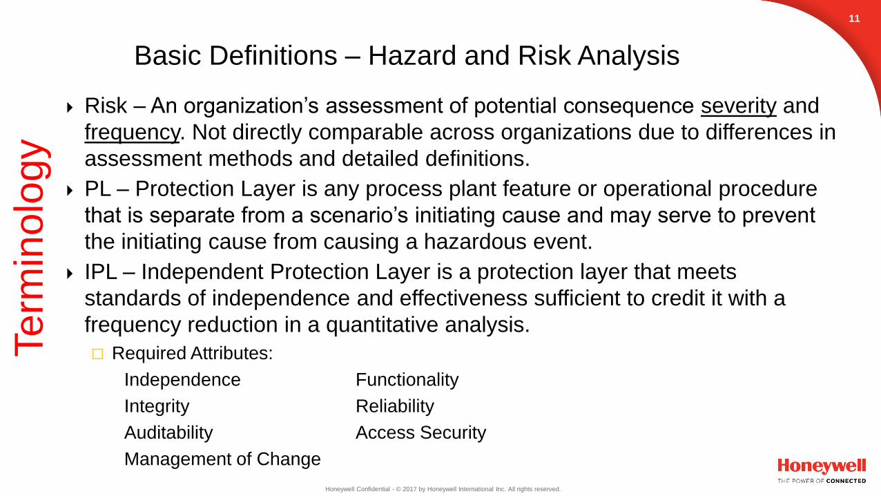
Risk – An organization’s assessment of potential consequence severity and
frequency. Not directly comparable across organizations due to differences in
assessment methods and detailed definitions.
PL – Protection Layer is any process plant feature or operational procedure
that is separate from a scenario’s initiating cause and may serve to prevent
the initiating cause from causing a hazardous event.
IPL – Independent Protection Layer is a protection layer that meets
standards of independence and effectiveness sufficient to credit it with a
frequency reduction in a quantitative analysis.
Required Attributes:
Independence Functionality
Integrity Reliability
Auditability Access Security
Management of Change
11
Te
rmin
olo
gy
Basic Definitions – Hazard and Risk Analysis
Page 13
Honeywell Confidential - © 2017 by Honeywell International Inc. All rights reserved.
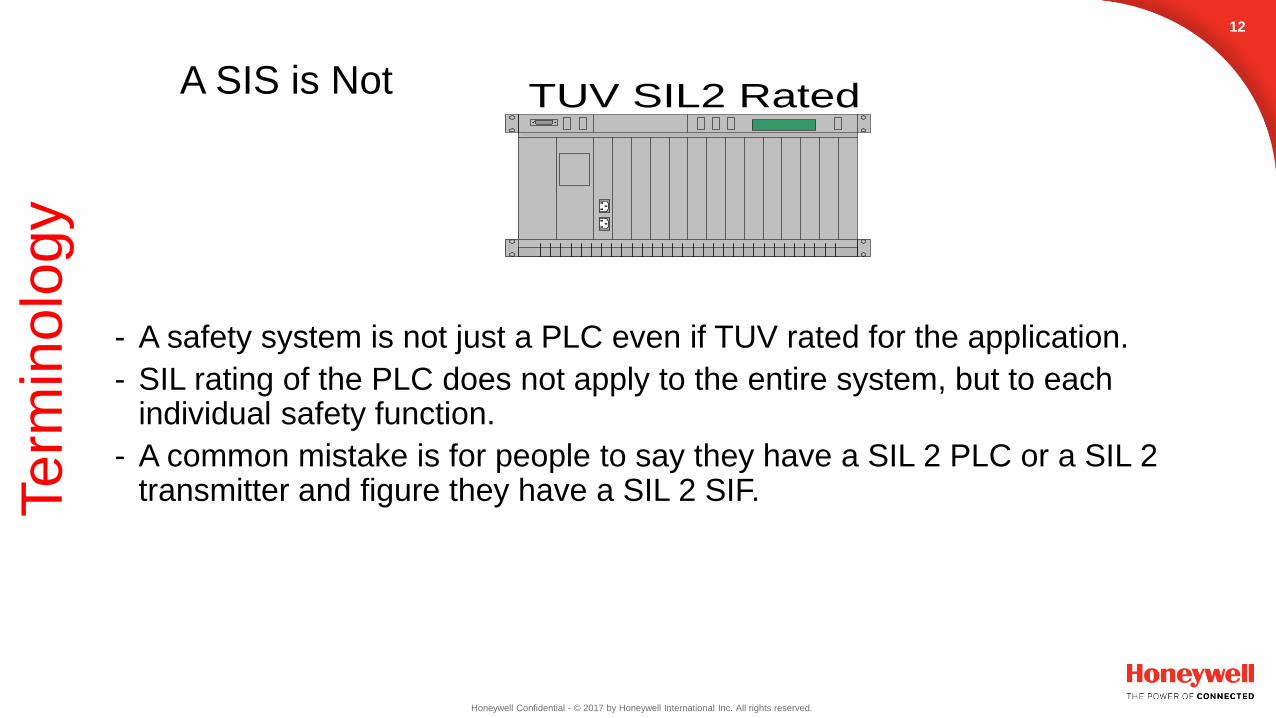
- A safety system is not just a PLC even if TUV rated for the application.
- SIL rating of the PLC does not apply to the entire system, but to each individual safety function.
- A common mistake is for people to say they have a SIL 2 PLC or a SIL 2 transmitter and figure they have a SIL 2 SIF.
TUV SIL2 Rated
12
A SIS is NotTe
rmin
olo
gy
Page 14
Honeywell Confidential - © 2017 by Honeywell International Inc. All rights reserved.
Every SIF has it’s own SIL rating
Diagram of Process Plant type installation
DCS
`
SIS
PT
PCV
SDV
SIF
COLUMN
PT
132. S
IS v
s. S
IF
Safety Instrumented Function (SIF)Te
rmin
olo
gy
Page 15
Honeywell Confidential - © 2017 by Honeywell International Inc. All rights reserved.
1. T/F: Having a SIL3 rated PLC means you have a SIL 3 Safety Instrumented
System.
2. SIL stand for:
a. Safety Integrated Level
b. Safety Integrity Level
c. Safety Integrated Layer
d. Safety Instrumented Layer
3. T/F: A Safety Instrumented Function must be separate from the Initiating
Event.
14
Terminology TestTe
rmin
olo
gy
Page 16
Honeywell Confidential - © 2017 by Honeywell International Inc. All rights reserved.
Safety System Overview
15
Page 17
Honeywell Confidential - © 2017 by Honeywell International Inc. All rights reserved.
• OSHA Federal Regulation 29 CFR 1910.119
• ANSI/ISA-84.00.01-2004(IEC 61511-1 Mod)
- Known as ISA 84
• Guidelines for Safe Automation of Chemical Processes, CCPS, AIChE.
• NFPA
• API
• Plus many others applicable codes and standards
161
. R
egula
tions &
Sta
ndard
s
Regulations and StandardsS
afe
ty S
yste
m O
ve
rvie
w
Page 18
Honeywell Confidential - © 2017 by Honeywell International Inc. All rights reserved.
Engineering Considerations
17
Page 19
Honeywell Confidential - © 2017 by Honeywell International Inc. All rights reserved.
Safety
Reliability Cost
SIS
Safety◦ personnel safety
◦ environmental impact
Reliability◦ financial impact
loss of production
equipment damage
minimization of nuisance trips
Cost◦ Design
◦ Maintenance
◦ Upgrades and scalability
184. K
ey C
onsid
era
tions
Key Engineering ConsiderationsE
ngin
ee
rin
g C
on
sid
era
tio
ns
Page 20
Honeywell Confidential - © 2017 by Honeywell International Inc. All rights reserved.
ISA 84 requires a “process hazard and risk assessment” (H&RA)
be carried out to determine the safety functions / risk reduction
requirements related to SIS.
Determines the required SIL rating for a SIF.
The H&RA documentation provides a linkage between SIF and specific
scenarios they are designed to protect.
193
. H
azard
and R
isk A
ssessm
ent
Hazard and Risk AssessmentE
ngin
ee
rin
g C
on
sid
era
tio
ns
Page 21
Honeywell Confidential - © 2017 by Honeywell International Inc. All rights reserved.
• A Risk matrix shows a relationship between Severity and Frequency that may be acceptable to an organization.
• Severity is a prediction and Frequency is an estimate. These systems quantify decision making with respect to applying resources to improve safety.
• Part of an overall detailed H&RA procedure.
Example Risk Table
Risk Tolerance
Frequency
(event per yr)
1x10⁻² 1x10⁻³ 1x10⁻⁴ 1x10⁻⁵
Consequence
Category
I II III IV
Personnel Safety
Minor Injuries,
No serious
injuries
Single serious
injury or multiple
minor injuries
Multiple serious
injuries
One or more
fatalities
Public Safety
No off-site
health or safety
consequences
No off-site health
or safety
consequence
Off-site injuries Off-site fatality
EnvironmentalReportable quantity
released
Reversible, self
correcting affect
Reversible
impact to non
sensitive
area
Impact to
sensitive area
or extended cleanup
required
Public Relations None
Letters or
calls of
complaint from
local public
Local news
coverage,
damage to public
image
National new
coverage or
threat to right to
continue
operations
Business Impact <$100,000$100,000 -
$1,000,000
$1,000,000 -
$10,000,000>$10,000,000
3. H
azard
and R
isk A
ssessm
ent
Hazard and Risk AssessmentE
ngin
ee
rin
g C
on
sid
era
tio
ns
Page 22
Honeywell Confidential - © 2017 by Honeywell International Inc. All rights reserved.
Design H&RA Methods
Risk Reduction Credits
Event Tree
LOPA Equations
Others as defined and adopted by user companies
- LOPA Equations represent a process of comparing event tree results with
user company risk tolerance requirements.
- LOPA is widely used in the process industries in the United States and is
used in examples below.
213
. H
azard
and R
isk A
ssessm
ent
Hazard and Risk AssessmentE
ngin
ee
rin
g C
on
sid
era
tio
ns
Page 23
Honeywell Confidential - © 2017 by Honeywell International Inc. All rights reserved.
22
Hazard and Risk Assessment
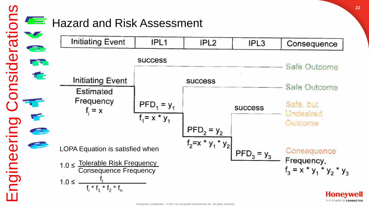
LOPA Equation is satisfied when
1.0 ≤
1.0 ≤
Tolerable Risk Frequency
fi * f1 * f2 * fn
ft
Consequence Frequency
En
gin
ee
rin
g C
on
sid
era
tio
ns
Page 24
Honeywell Confidential - © 2017 by Honeywell International Inc. All rights reserved.
231
. S
IS D
esig
n C
oncepts
SIS Design Concepts
Basically, the SIL defines the level of avaliability required to bridge the gap between the allowable level of risk and the layers of protection designed in the process.
How do we know our system meets the SIL rating?1. A detailed study of each device in the SIF loop must be analyzed to determine the average
PFD for the entire loop.
2. Industry and vendor data is available for these devices but it’s up to the engineer to interpret the data and fashion these as a system in order to determine the overall average PFD. a. OREDA publications
b. IEEE 500
c. Vendor data (common source)
d. Privately published compilations of data (common source)
e. First hand (user) data in the process application (best source)
En
gin
ee
rin
g C
on
sid
era
tio
ns
Page 25
Honeywell Confidential - © 2017 by Honeywell International Inc. All rights reserved.
How do we know our system meets the SIL rating? Contd.
The PFD number is required for the necessary SIL rating as shown in the table below.
Remember, these include all transmitters, the logic solver (each individual piece) and the final safety elements like shutdown valves and solenoids. Some sample PFD data is shown below taken from some of the above reference sources.
N
Ai
N
Ai
iavg PPPP )(
Device (Generic) Average PFD Data
(Test interval once
per year)
Manual Stop
Flow Switch
Pressure Transmitter
Safety PLC Specific to Vendor
Solenoid
Butterfly Valve
51090.8 x21002.1 x31039.3 x
31047.8 x21069.1 x
7.S
afe
ty Inte
grity
Level
241
. S
IS D
esig
n C
oncepts
En
gin
ee
rin
g C
on
sid
era
tio
ns
SIS Design Concepts
You are
only as
strong as
your
weakest
link!
Page 26
Honeywell Confidential - © 2017 by Honeywell International Inc. All rights reserved.
Our focus today
En
gin
ee
rin
g C
on
sid
era
tio
ns
Page 27
Honeywell Confidential - © 2017 by Honeywell International Inc. All rights reserved.
1. Things one might consider when designing a Safety Instrumented System
are: (list all that apply)
a. Cost
b. Reliability
c. Safety
d. Are the fish biting
2. T/F: ISA 84 requires a “process hazard and risk assessment” (H&RA) be
carried out to determine the safety functions / risk reduction requirements
related to SIS.
3. T/F: To get reliability data to document my PFD numbers I must do years of
extensive testing.
26
Safety System Design TestE
ngin
ee
rin
g C
on
sid
era
tio
ns
Page 28
Honeywell Confidential - © 2017 by Honeywell International Inc. All rights reserved.
Application
27
Page 29
Honeywell Confidential - © 2017 by Honeywell International Inc. All rights reserved.
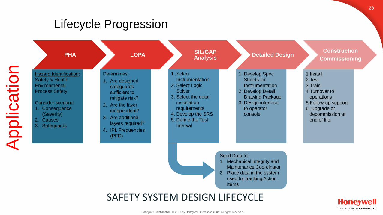
PHA LOPASIL/GAP Analysis
Detailed DesignConstruction
Commissioning
Hazard Identification:
Safety & Health
Environmental
Process Safety
Consider scenario:
1. Consequence
(Severity)
2. Causes
3. Safeguards
Determines:
1. Are designed
safeguards
sufficient to
mitigate risk?
2. Are the layer
independent?
3. Are additional
layers required?
4. IPL Frequencies
(PFD)
1. Select
Instrumentation
2. Select Logic
Solver
3. Select the detail
installation
requirements
4. Develop the SRS
5. Define the Test
Interval
1. Develop Spec
Sheets for
Instrumentation
2. Develop Detail
Drawing Package
3. Design interface
to operator
console
1.Install
2.Test
3.Train
4.Turnover to
operations
5.Follow-up support
6. Upgrade or
decommission at
end of life.
Send Data to:
1. Mechanical Integrity and
Maintenance Coordinator
2. Place data in the system
used for tracking Action
Items
SAFETY SYSTEM DESIGN LIFECYCLE
28
Lifecycle ProgressionA
pp
lica
tio
n
Page 30
Honeywell Confidential - © 2017 by Honeywell International Inc. All rights reserved.
DCS
`
PCV
COLUMN
PT
PRV
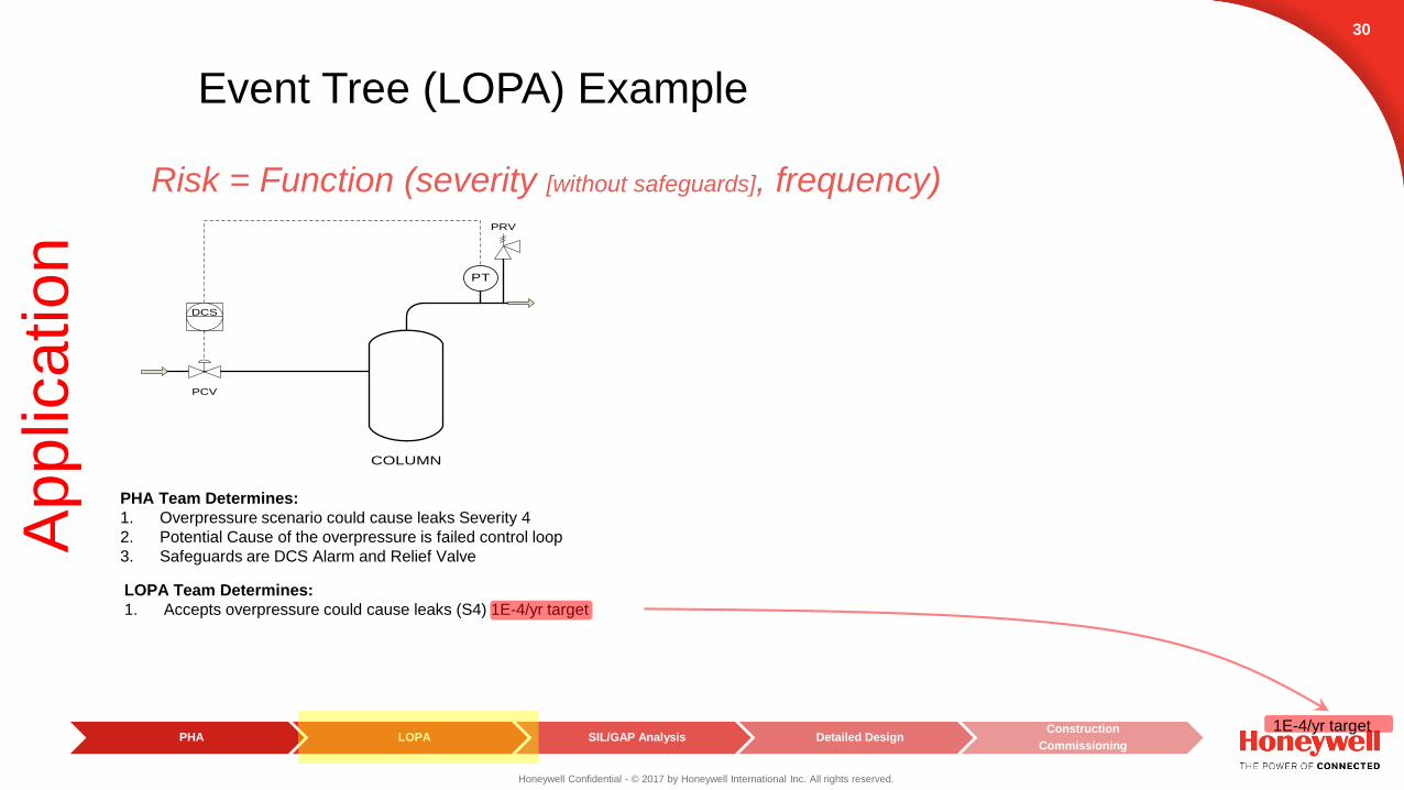
Risk = Function (severity [without safeguards], frequency)
PHA Team Determines:
1. Overpressure scenario could fail the tower Severity 4
2. Potential Cause of the overpressure is failed control loop
3. Safeguards are DCS Alarm and Relief Valve
PHA LOPA SIL/GAP Analysis Detailed DesignConstruction
Commissioning
29
Event Tree (LOPA) ExampleA
pp
lica
tio
n
Page 31
Honeywell Confidential - © 2017 by Honeywell International Inc. All rights reserved.
DCS
`
PCV
COLUMN
PT
PRV
Risk = Function (severity [without safeguards], frequency)
PHA Team Determines:
1. Overpressure scenario could cause leaks Severity 4
2. Potential Cause of the overpressure is failed control loop
3. Safeguards are DCS Alarm and Relief Valve
LOPA Team Determines:
1. Accepts overpressure could cause leaks (S4) 1E-4/yr target
PHA LOPA SIL/GAP Analysis Detailed DesignConstruction
Commissioning
30
1E-4/yr target
Event Tree (LOPA) ExampleA
pp
lica
tio
n
Page 32
Honeywell Confidential - © 2017 by Honeywell International Inc. All rights reserved.
DCS
`
PCV
COLUMN
PT
PRV
Risk = Function (severity [without safeguards], frequency)
PHA Team Determines:
1. Overpressure scenario could cause leaks Severity 4
2. Potential Cause of the overpressure is failed control loop
3. Safeguards are DCS Alarm and Relief Valve
PHA LOPA SIL/GAP Analysis Detailed DesignConstruction
Commissioning
31
LOPA Team Determines:
1. Accepts overpressure could cause leaks (S4) 1E-4/yr target
2. Accepts the potential cause of the
overpressure is failed control loop (BPCS Failure)
1E-4/yr target
90%
10%
Event Tree (LOPA) ExampleA
pp
lica
tio
n
Page 33
Honeywell Confidential - © 2017 by Honeywell International Inc. All rights reserved.
DCS
`
PCV
COLUMN
PT
PRV
Risk = Function (severity [without safeguards], frequency)
PHA Team Determines:
1. Overpressure scenario could cause leaks Severity 4
2. Potential Cause of the overpressure is failed control loop
3. Safeguards are DCS Alarm and Relief Valve
LOPA Team Determines:
1. Accepts overpressure could cause leaks (S4) 1E-4/yr target
2. Accepts the potential cause of the
overpressure is failed control loop (BPCS Failure)
3. Determines as independent layers the safeguards are relief valve
but not credit the DCS Alarm due to not being independent
PHA LOPA SIL/GAP Analysis Detailed DesignConstruction
Commissioning
32
1E-4/yr target
90%
10%99.9%
0.1%
0.1%
Event Tree (LOPA) ExampleA
pp
lica
tio
n
Page 34
Honeywell Confidential - © 2017 by Honeywell International Inc. All rights reserved.
DCS
`
PCV
COLUMN
PT
PRV
Risk = Function (severity [without safeguards], frequency)
PHA Team Determines:
1. Overpressure scenario could cause leaks Severity 4
2. Potential Cause of the overpressure is failed control loop
3. Safeguards are DCS Alarm and Relief Valve
LOPA Team Determines:
1. Accepts overpressure could cause leaks (S4) 1E-4/yr target
2. Accepts the potential cause of the
overpressure is failed control loop (BPCS Failure)
3. Determines as independent layers the safeguards are relief valve
but not credit the DCS Alarm due to not being independent
4. Determine the need for an additional IPL.
PHA LOPA SIL/GAP Analysis Detailed DesignConstruction
Commissioning
33
1E-4/yr target
90%
10%99.9%
0.1%
0.1% 99.99%
0.01%
Event Tree (LOPA) ExampleA
pp
lica
tio
n
Page 35
Honeywell Confidential - © 2017 by Honeywell International Inc. All rights reserved.
DCS
`
PCV
COLUMN
PT
PRV
Risk = Function (severity [without safeguards], frequency)
PHA Team Determines:
1. Overpressure scenario could cause leaks Severity 4
2. Potential Cause of the overpressure is failed control loop
3. Safeguards are DCS Alarm and Relief Valve
LOPA Team Determines:
1. Accepts overpressure could cause leaks (S4) 1E-4/yr target
2. Accepts the potential cause of the
overpressure is failed control loop (BPCS Failure)
3. Determines as independent layers the safeguards are relief valve
but not credit the DCS Alarm due to not being independent
4. Determine the need for an additional IPL.
Safety
Integrity
Level
(SIL)
Average
Probability of
Failure on
Demand (PFD)
Availability (%) Corresponding
Risk Reduction
Credit
SIL-4 99.99 - 99.999 4
SIL-3 99.9 - 99.99 3
SIL-2 99 - 99.9 2
SIL-1 90 - 99 1
SAFETY INTEGRITY LEVEL
Demand Mode of Operation
54 10 to10
43 10 to10
32 10 to10
21 10 to10
PHA LOPA SIL/GAP Analysis Detailed DesignConstruction
Commissioning
34
Design and
SIL Verification
Event Tree (LOPA) ExampleA
pp
lica
tio
n
PFD = 1E-1 SIS
Required
Page 36
Honeywell Confidential - © 2017 by Honeywell International Inc. All rights reserved.
Risk = Function (severity [without safeguards], frequency)
PHA Team Determines:
1. Overpressure scenario could cause leaks Severity 4
2. Potential Cause of the overpressure is failed control loop
3. Safeguards are DCS Alarm and Relief Valve
LOPA Team Determines:
1. Accepts overpressure could cause leaks (S4) 1E-4/yr target
2. Accepts the potential cause of the
overpressure is failed control loop (BPCS Failure)
3. Determines as independent layers the safeguards are relief valve
but not credit the DCS Alarm due to not being independent
4. Determine the need for an additional IPL.
Safety
Integrity
Level
(SIL)
Average
Probability of
Failure on
Demand (PFD)
Availability (%) Corresponding
Risk Reduction
Credit
SIL-4 99.99 - 99.999 4
SIL-3 99.9 - 99.99 3
SIL-2 99 - 99.9 2
SIL-1 90 - 99 1
SAFETY INTEGRITY LEVEL
Demand Mode of Operation
54 10 to10
43 10 to10
32 10 to10
21 10 to10
DCS
`
SIS
PT
PCV
SDV
SIF
COLUMN
PT
PRV
PHA LOPA SIL/GAP Analysis Detailed DesignConstruction
Commissioning
35
PFD = 1E-1 SIS
Required
Detail Design
Safety Function ExampleA
pp
lica
tio
n
Page 37
Honeywell Confidential - © 2017 by Honeywell International Inc. All rights reserved.
36
PHA LOPA SIL/GAP Analysis Detailed DesignConstruction
Commissioning
Safety Requirements SpecificationA
pp
lica
tio
n
Page 38
Honeywell Confidential - © 2017 by Honeywell International Inc. All rights reserved.
37
Build and Commission the SIS
– The Logic Solver and field instrumentation must be installed per the SRS. If changes are found to be necessary for a particular SIF, the SRS and all associated documentation / SIL Calculations need to be updated to ensure the functional and availability requirements of the H&RA are still met.
– During the build process Factory Acceptance Testing (FAT) is carried out to ensure the SRS requirements are being adhered to.
– Construction and Commissioning
– SIS safety Validation, sometimes integrated with Site Acceptance Testing (SAT), is the final step to confirm that all components from input instruments to final elements (e.g. block valves). Work per the original intent.
PHA LOPA SIL/GAP Analysis Detailed DesignConstruction
Commissioning
Ap
plic
atio
n
Page 39
Honeywell Confidential - © 2017 by Honeywell International Inc. All rights reserved.
38
Operate and Support the SIS
– The objective of the ISA 84 clause is: “To ensure the required SIL of each safety instrumented function is maintained during operation and maintenance.”
– SIF operation concerns include training operators in the function of SIF, including:• Manual activation.
• Reset requirements.
• Actions taken following demand on the system.
• Training maintenance on how to sustain the full functional performance.
• Controlling bypass of SIF in such a way that it is not done when risk mitigation is required or compensating measures are provided to substitute for the risk mitigation that is missing while the SIF is in bypass.
– Support concerns include training maintenance in actions which maintain the performance of the SIF including:
• Proof Testing.
• Bypass communication with Operations.
• Allowable component replacements.
• Post maintenance verification of function.
SIL/GAP Analysis Detailed DesignConstruction
CommissioningOperation and Maintenance
Ap
plic
atio
n
Page 40
Honeywell Confidential - © 2017 by Honeywell International Inc. All rights reserved.
1. The Safety System design should begin with
a. SIL Analysis
b. Safety Manager Drawings
c. HAZOP or PHA
d. LOPA
2. T/F: All companies must have the same risk tolerances per ISA S84.
3. The Safety Requirement Specification (SRS) outlines the following:
a. The Logic Solver
b. Field Instrumentation
c. Both A and B
d. None of the above.
39
Application TestA
pp
lica
tio
n
Page 41
Honeywell Confidential - © 2017 by Honeywell International Inc. All rights reserved.
- A Safety Instrumented System is all the instrumentation together designed to bring the process into a safe state, without relying on mechanical or physical protective devices, following an upset or abnormal operating condition
- Each SIF (Safety Loop) has an independent SIL rating. SIL rating does not apply to an entire system.
- SIL rating requirement is determined by a hazard and risk assessment.
- A balance of safety, reliability and cost all are considered during the engineering process of a safety instrumented system.
QUESTIONS?
40
Clo
sin
gSIS is Engineered Risk Reduction