49
Sistemas Digitais I LESI - 2º ano Lesson 6 - Combinational Design Practices UNIVERSIDADE DO MINHO ESCOLA DE ENGENHARIA Prof. João Miguel Fernandes ([email protected]) Dept. Informática

Sistemas Digitais ILESI - 2º ano
Lesson 6 - Combinational Design Practices
UNIVERSIDADE DO MINHO
ESCOLA DE ENGENHARIA
Prof. João Miguel Fernandes([email protected])
Dept. Informática
6. Combinational Practices- PLDs (1) -
§ The first PLDs were Programmable Logic Arrays (PLAs).§ A PLA is a combinational, 2-level AND-OR device that can be
programmed to realise any sum-of-products logic expression.§ A PLA is limited by:
– the number of inputs (n)– the number of outputs (m)– the number of product terms (p)
§ We refer to an “n x m PLA with p product terms”. Usually, p << 2 n.§ An n x m PLA with p product terms contains p 2n-input AND gates
and m p-input OR gates.
6. Combinational Practices- PLDs (2) -
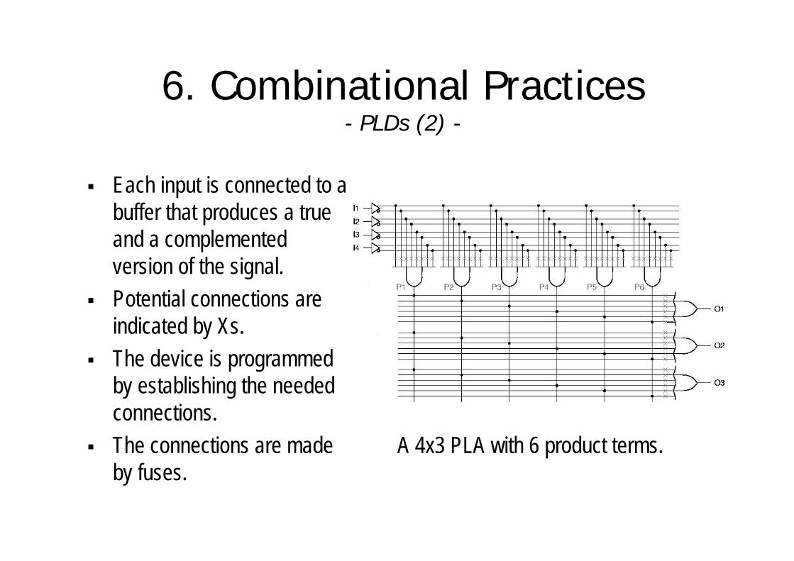
A 4x3 PLA with 6 product terms.
§ Each input is connected to a buffer that produces a true and a complemented version of the signal.
§ Potential connections are indicated by Xs.
§ The device is programmed by establishing the needed connections.
§ The connections are made by fuses.

6. Combinational Practices- PLDs (3) -
§ Compact representation of the 4x3 PLA with 6 product terms.
§ O1 = I1·I2 + I1’·I2’·I3’·I4’O2 = I1·I3’ + I1’·I3·I4 + I2O3 = I1·I2 + I1·I3’ + I1’·I2’·I4’

6. Combinational Practices- PLDs (4) -
§ Another PLD is PAL (Programmable Array Logic).
§ A PAL device has a fixed OR array.
§ In a PAL, product terms are not shared by the outputs.
§ A PAL is usually faster than a similar PLA.

6. Combinational Practices- PLDs (4) -
§ Part of the logic diagram of the PAL 16L8.

6. Combinational Practices- Decoders (1) -
§ A decoder is a circuit that converts coded inputs into coded outputs.§ Usually, the input code has fewer bits than the output code.§ The most common decoder is an n-to-2n or binary decoder.§ A binary decoder is used when one of 2n outputs needs to be
activated based on an n-bit input value.
6. Combinational Practices- Decoders (2) -
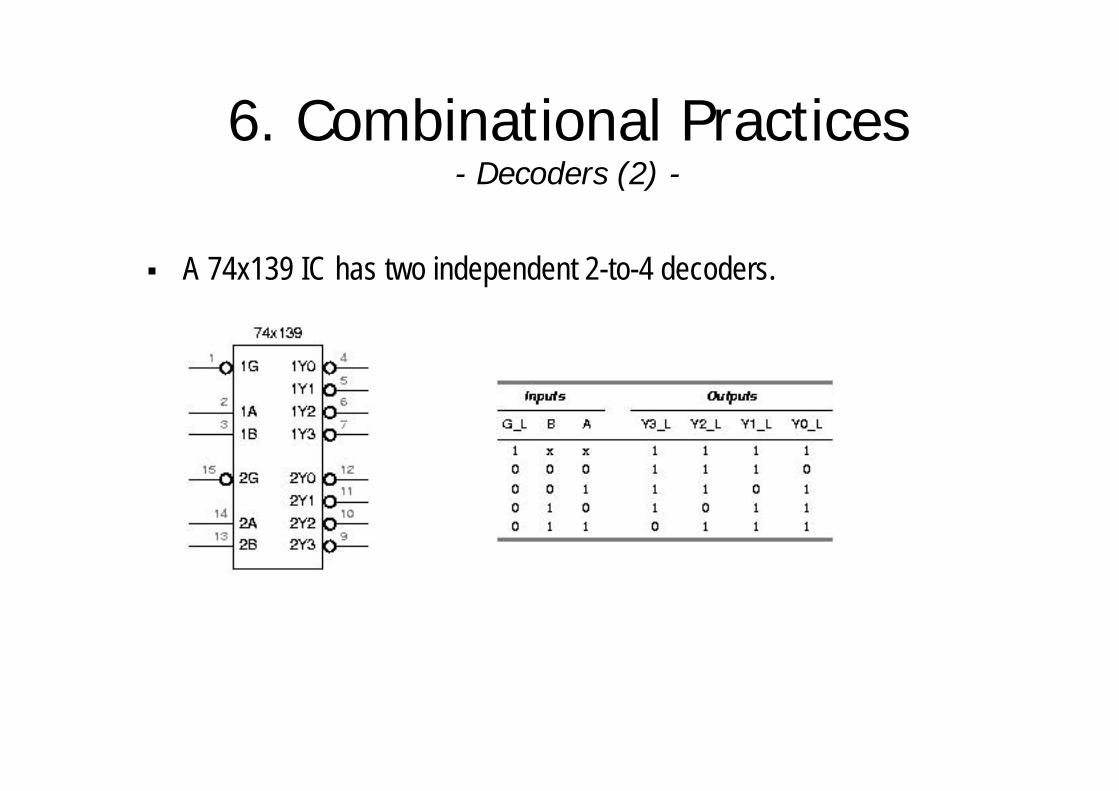
§ A 74x139 IC has two independent 2-to-4 decoders.
6. Combinational Practices- Decoders (3) -
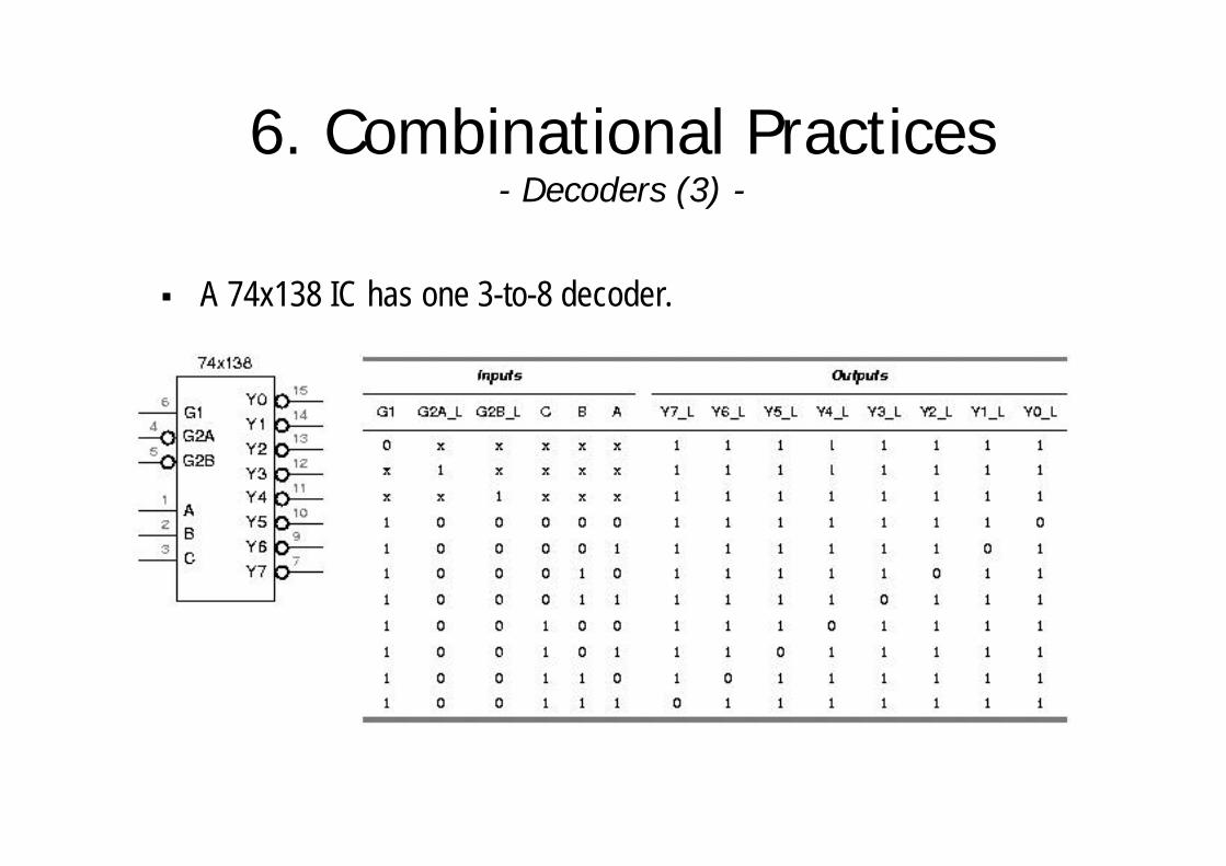
§ A 74x138 IC has one 3-to-8 decoder.

6. Combinational Practices- Decoders (4) -
§ Multiple decoders can be used to decode larger code words.
§ The top decoder (U1) is enabled when N3 is 0, and the bottom decoder (U2) is enabled when N3 is 1.
§ To handle larger code words, decoders can be cascaded hierarchically.

6. Combinational Practices- Decoders (5) -
§ To handle larger code words, decoders can be cascaded hierarchically.
§ A 5-to-32 decoder can be built with one 2-to-4 and four 3-to-8 decoders.
§ The 2-to-4 decoder treats the high order bits.
§ The 3-to-8 decoders treat the low-order bits.

6. Combinational Practices- Decoders (6) -
§ There are several ways to write decoders in VHDL.§ The most primitive would be to write a structural description
equivalent to the logic circuit on slide 7.
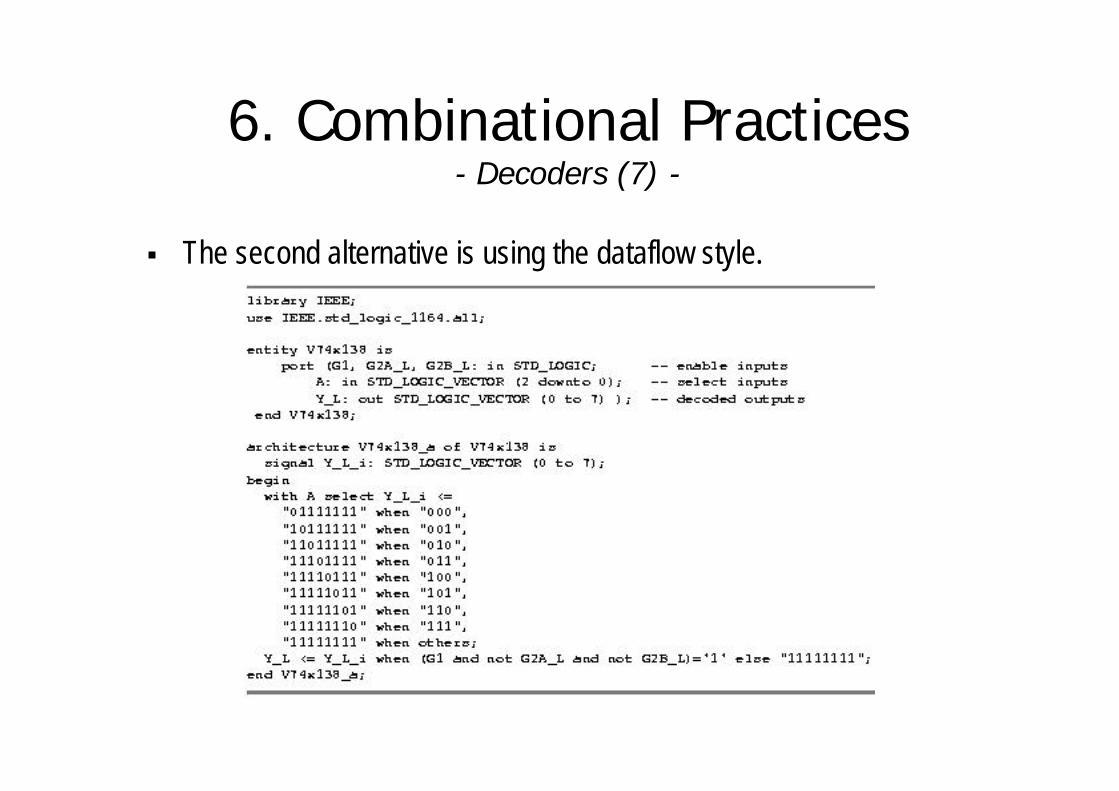
6. Combinational Practices- Decoders (7) -
§ The second alternative is using the dataflow style.

6. Combinational Practices- Decoders (8) -
§ Another alternative is using the behavioral style.
6. Combinational Practices- 7-Segment Decoders (1) -
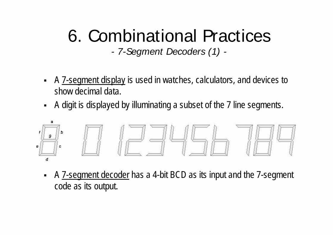
§ A 7-segment display is used in watches, calculators, and devices to show decimal data.
§ A digit is displayed by illuminating a subset of the 7 line segments.
§ A 7-segment decoder has a 4-bit BCD as its input and the 7-segment code as its output.

6. Combinational Practices- 7-Segment Decoders (2) -
§ Exercise 1:Obtain minimised expressions for outputs of the 7-segment decoder.
§ Exercise 2:Write a VHDL description of a 7-segment decoder.

6. Combinational Practices- Encoders (1) -
§ An encoder is a circuit whose output code has normally fewer bits than its input code.
§ The simplest encoder to build is a 2n-to-n or binary encoder. It has the opposite function as a binary encoder.
§ Equations for an 8-to-3 encoder :Y0 = I1 + I3 + I5 + I7Y1 = I2 + I3 + I6 + I7Y2 = I4 + I5 + I6 + I7
§ Only 1 input is active at a time. What happens if 2 inputs are asserted (ex: I2 and I4)?
6. Combinational Practices- Encoders (2) -
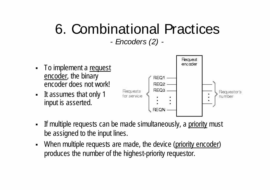
§ To implement a request encoder, the binary encoder does not work!
§ It assumes that only 1 input is asserted.
§ If multiple requests can be made simultaneously, a priority must be assigned to the input lines.
§ When multiple requests are made, the device (priority encoder) produces the number of the highest-priority requestor.

6. Combinational Practices- Encoders (3) -
§ Input I7 has the highest priority.§ Outputs A2-A0 contain the number of the
highest-priority asserted input, if any.§ The IDLE output is asserted if no inputs
are asserted.§ Intermediate variable Hi is 1, if Ii
is the highest priority 1-input:H7 = I7 H6 = I6·I7’H5 = I5·I6’·I7’ H4 = I4·I5’·I6’·I7’... (similar equations for H3-H0)
§ A0 = H1 + H3 + H5 + H7A1 = H2 + H3 + H6 + H7A2 = H4 + H5 + H6 + H7
§ IDLE= I0’·I1’·I2’·I3’·I4’·I5’·I6’·I7’

6. Combinational Practices- Multiplexers (1) -
§ A multiplexer (mux) is a digital switch.§ It connects data from one of n sources
to its output. § The SEL input selects among the n
sources, so s = log2 n.§ When EN=0, Y=0;
When EN=1, the mux is working.
§ Multiplexers are used in computers between the processor’s registers and its ALU, to select among a set of registers which one is connected to the ALU.

6. Combinational Practices- Multiplexers (2) -
§ A 74x151 IC has one 8-input, 1-bit multiplexer.
§ The select inputs are named A,B,C, where C is the MSB.
§ The enable input EN_L is active low.
§ Both active-low and high versions of the output are provided
6. Combinational Practices- Multiplexers (3) -
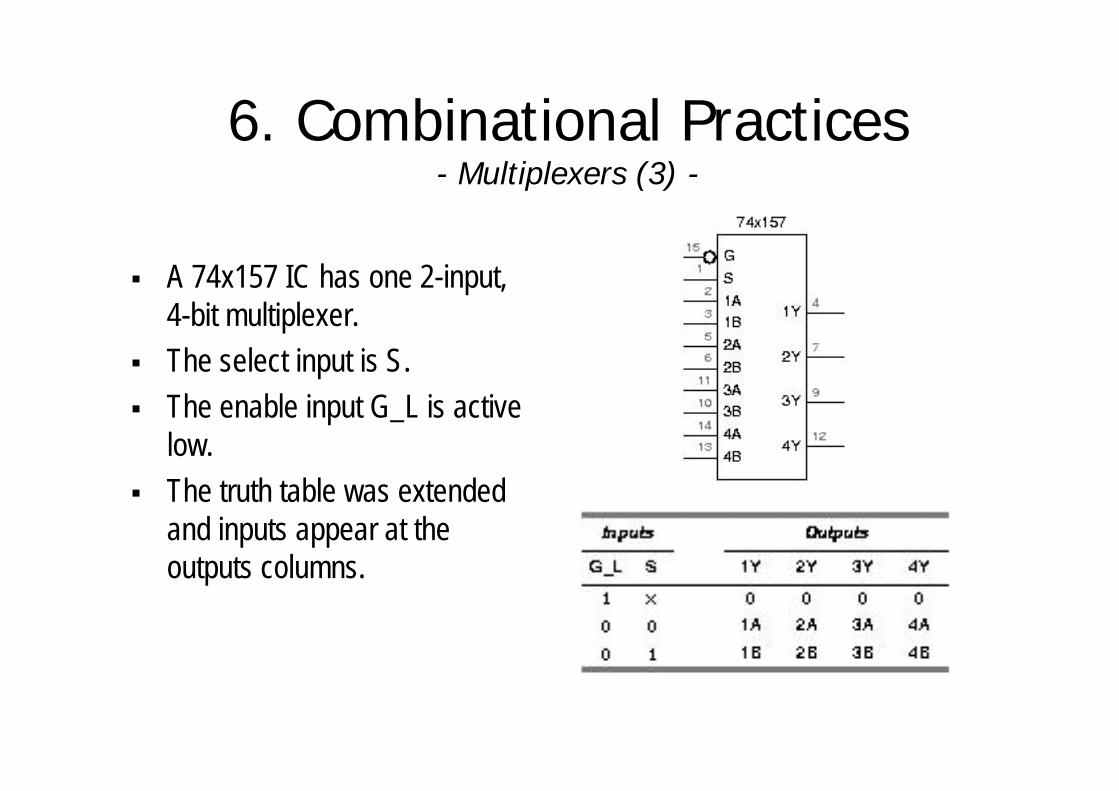
§ A 74x157 IC has one 2-input, 4-bit multiplexer.
§ The select input is S.§ The enable input G_L is active
low.§ The truth table was extended
and inputs appear at the outputs columns.
6. Combinational Practices- Multiplexers (4) -
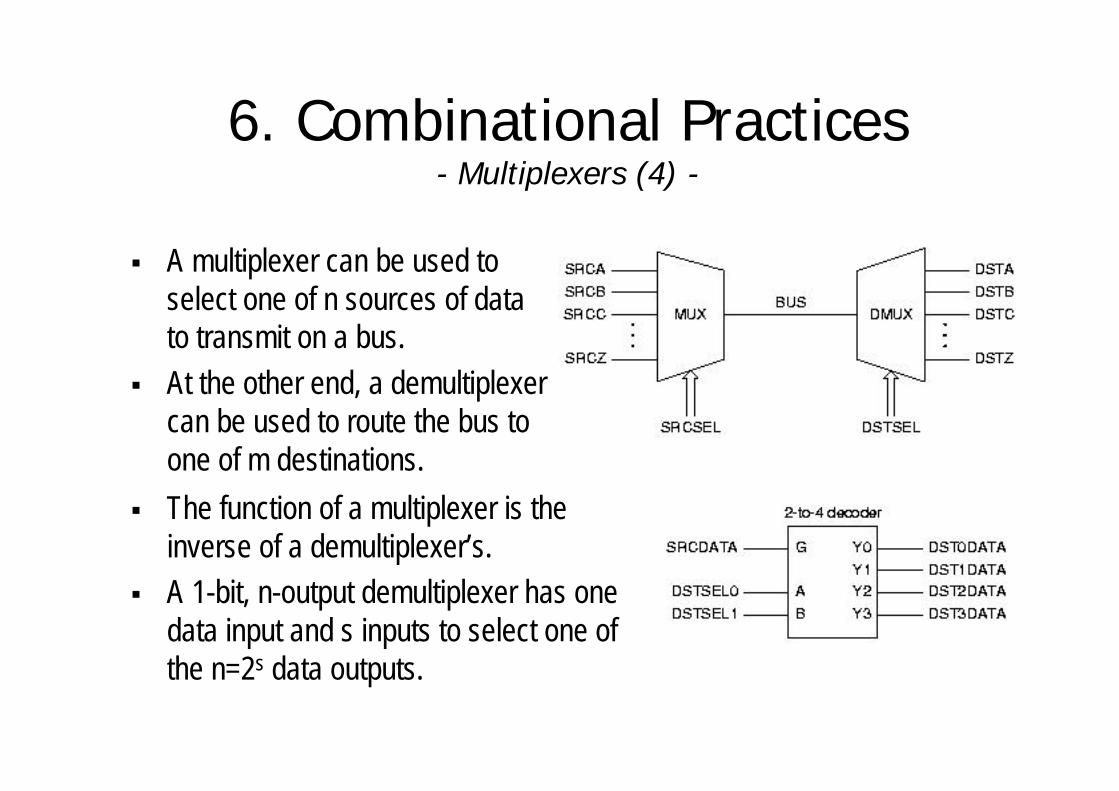
§ A multiplexer can be used to select one of n sources of data to transmit on a bus.
§ At the other end, a demultiplexer can be used to route the bus to one of m destinations.
§ The function of a multiplexer is the inverse of a demultiplexer’s.
§ A 1-bit, n-output demultiplexer has one data input and s inputs to select one of the n=2s data outputs.

6. Combinational Practices- Multiplexers (5) -
§ It is easy to describe multiplexers in VHDL.§ In the dataflow style, a SELECT statement is required.

6. Combinational Practices- Multiplexers (6) -
§ In a behavioural architecture, a CASE statement is used.
§ It is easy to customise the selection criteria in a VHDL multiplexerprogram.
6. Combinational Practices- XOR and Parity Circuits (1) -
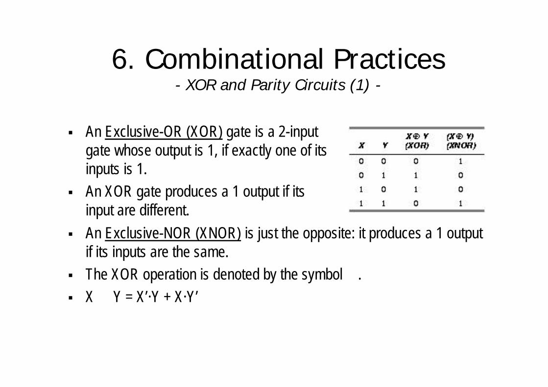
§ An Exclusive-OR (XOR) gate is a 2-input gate whose output is 1, if exactly one of its inputs is 1.
§ An XOR gate produces a 1 output if its input are different.
§ An Exclusive-NOR (XNOR) is just the opposite: it produces a 1 output if its inputs are the same.
§ The XOR operation is denoted by the symbol ⊕.§ X ⊕ Y = X’·Y + X·Y’

6. Combinational Practices- XOR and Parity Circuits (2) -
§ These alternatives are a consequence of the following rule:– Any two signals (inputs or output) of an XOR or XNOR gate may be
complemented without changing the resulting logic function.
§ In bubble-to-bubble design we choose the symbol that is most expressive of the logic function being performed.
§ There are 4 symbols for each XOR and XNOR function.

6. Combinational Practices- XOR and Parity Circuits (3) -
§ n XOR gates may be cascaded to form a circuit with n+1 inputs and a single output. This is a odd-parity circuit, because its output is 1 if an odd number of its inputs are 1.
§ If the output of either circuit is inverted, we get an even-parity circuit, whose output is 1 if an even number of its inputs are 1.
6. Combinational Practices- XOR and Parity Circuits (4) -
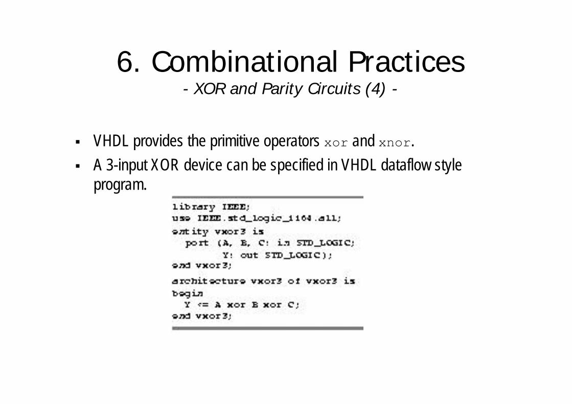
§ VHDL provides the primitive operators xor and xnor.
§ A 3-input XOR device can be specified in VHDL dataflow style program.
6. Combinational Practices- XOR and Parity Circuits (5) -
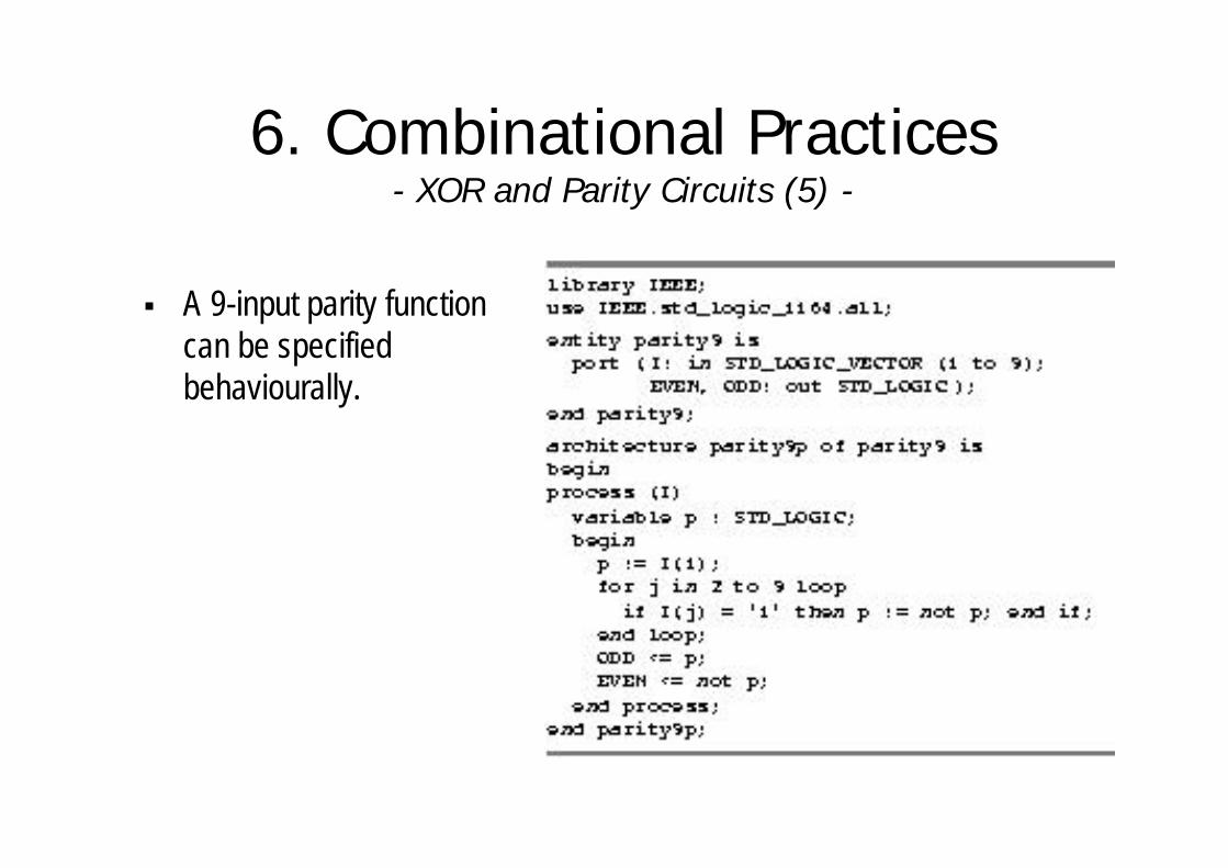
§ A 9-input parity function can be specified behaviourally.
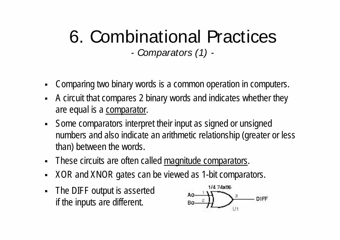
6. Combinational Practices- Comparators (1) -
§ Comparing two binary words is a common operation in computers.§ A circuit that compares 2 binary words and indicates whether they
are equal is a comparator.§ Some comparators interpret their input as signed or unsigned
numbers and also indicate an arithmetic relationship (greater or less than) between the words.
§ These circuits are often called magnitude comparators.§ XOR and XNOR gates can be viewed as 1-bit comparators.
§ The DIFF output is asserted if the inputs are different.
6. Combinational Practices- Comparators (2) -
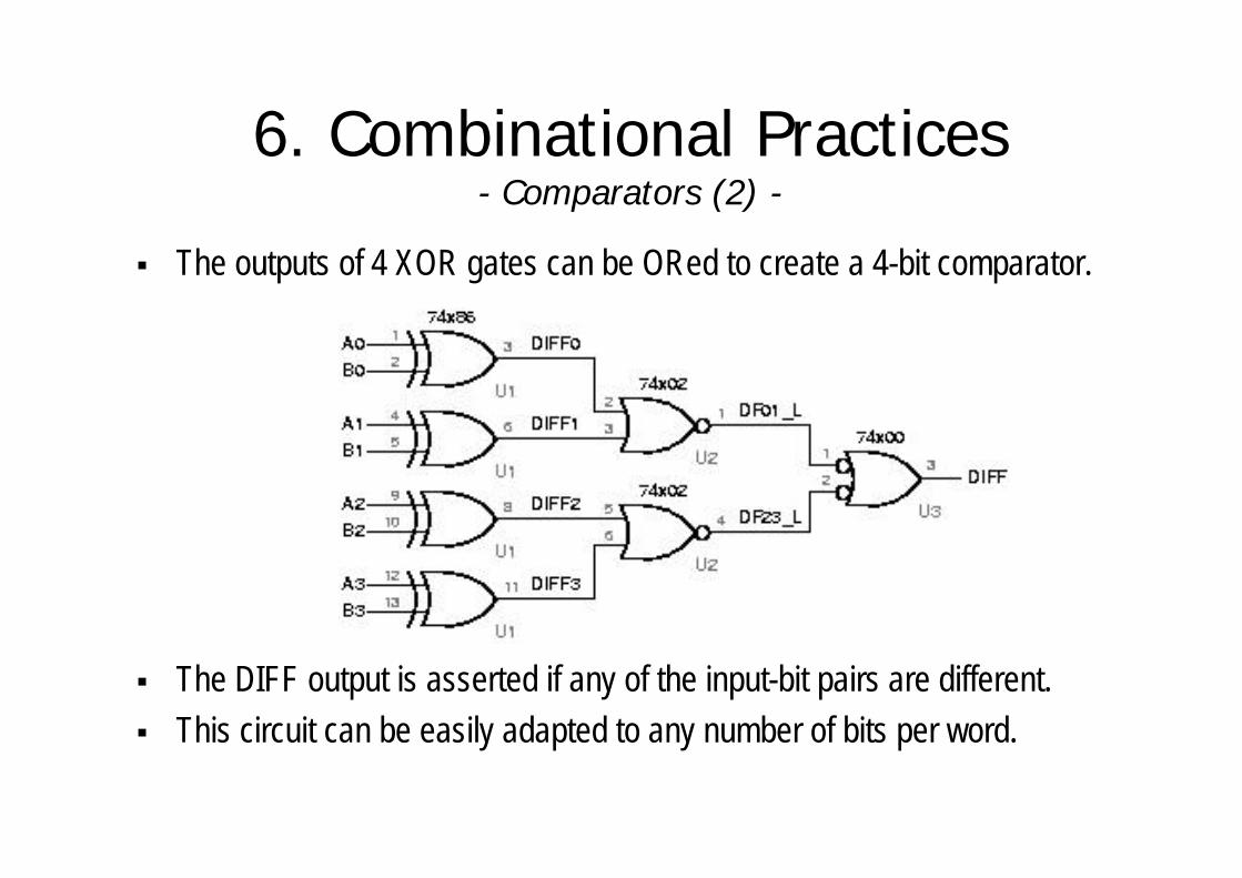
§ The outputs of 4 XOR gates can be ORed to create a 4-bit comparator.
§ The DIFF output is asserted if any of the input-bit pairs are different.§ This circuit can be easily adapted to any number of bits per word.

6. Combinational Practices- Comparators (3) -
§ An iterative circuit is a combinational circuit with the following structure.
§ The circuit contains n identical modules, each of which has both primary inputs and outputs and cascading inputs and outputs.
§ The left-most cascading inputs are usually connected to fixed values.
6. Combinational Practices- Comparators (4) -
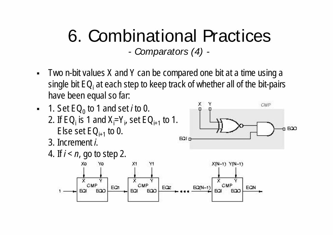
§ Two n-bit values X and Y can be compared one bit at a time using a single bit EQi at each step to keep track of whether all of the bit-pairs have been equal so far:
§ 1. Set EQ0 to 1 and set i to 0.2. If EQi is 1 and Xi=Yi, set EQi+1 to 1.
Else set EQi+1 to 0. 3. Increment i.4. If i < n, go to step 2.
6. Combinational Practices- Comparators (5) -
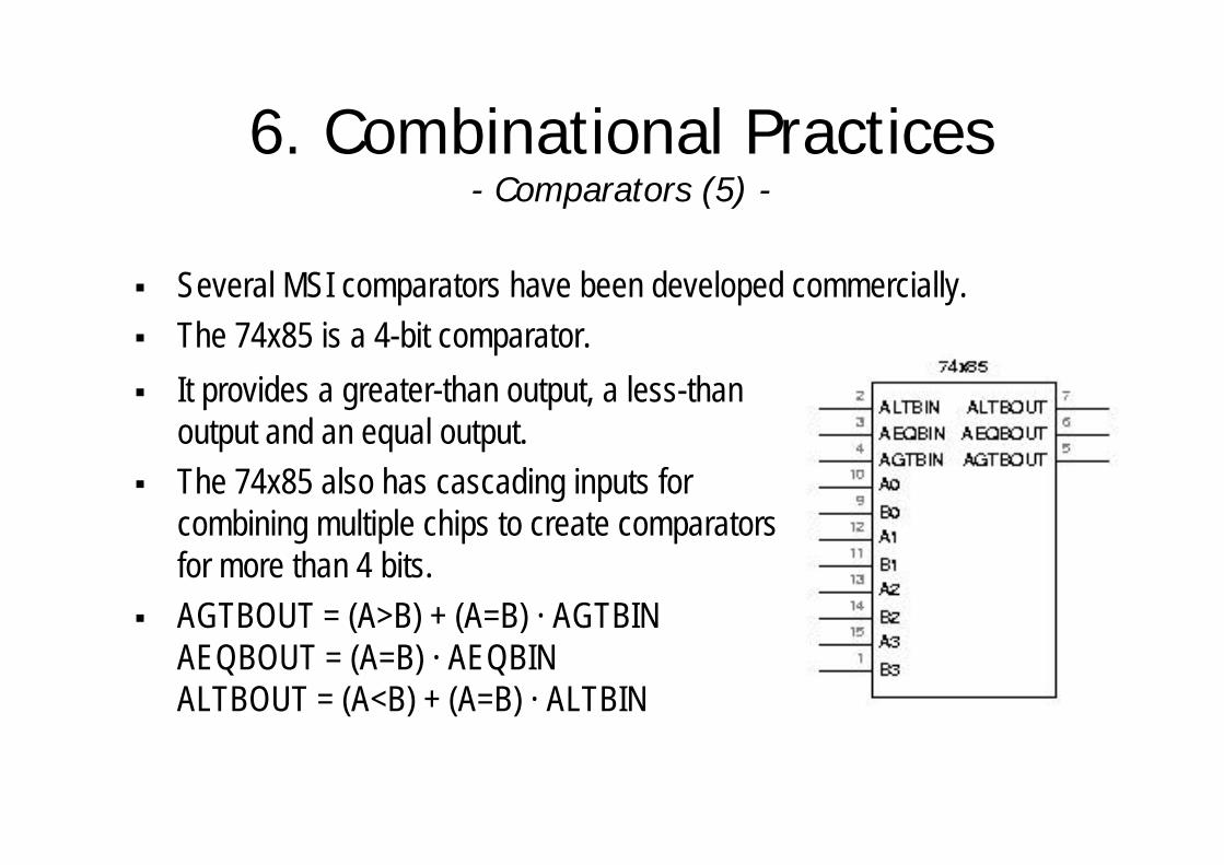
§ Several MSI comparators have been developed commercially.§ The 74x85 is a 4-bit comparator.
§ It provides a greater-than output, a less-than output and an equal output.
§ The 74x85 also has cascading inputs for combining multiple chips to create comparators for more than 4 bits.
§ AGTBOUT = (A>B) + (A=B) · AGTBINAEQBOUT = (A=B) · AEQBINALTBOUT = (A<B) + (A=B) · ALTBIN

6. Combinational Practices- Comparators (6) -
§ With three 74x85 circuits, a 12-bit comparator can be built.
6. Combinational Practices- Comparators (7) -
§ VHDL has comparison operators for all of its built-in types.§ Equality (=) and inequality (/=) operators apply to all types.
§ For array and record types, the operands must have equal size and structure, and the operands are compared component by component.
§ VHDL’s other comparison operators (>, <, >=, <=) apply only to integers, enumerated types and one-dimensional arrays of enumeration or integer types.
6. Combinational Practices- Adders, Subtractors and ALUs (1) -
§ Addition is the most commonly performed arithmetic operation in digital systems.
§ An adder combines two arithmetic operands using the addition rules.§ The same addition rules, and hence the same adders, are used for
both unsigned and 2’s complement numbers. § An adder can perform subtraction as the addition of the minuend and
the complemented subtrahend.§ A subtractor can also be built to perform subtraction directly.§ An ALU (Arithmetic and Logic Unit) performs addition, subtraction,
and other logical operations.

6. Combinational Practices- Adders, Subtractors and ALUs (2) -
§ The simplest adder, called a half adder, adds two 1-bit operands X and Y, producing a 2-bit sum.
§ The sum can range from 0 to 2, which requires two bits to express.§ The low-order bit of the sum may be named HS (half sum).§ The high-order bit of the sum may be named CO (carry out).§ The following equations can be written:
HS = X ⊕ Y = X·Y’ + X’·YCO = X·Y
§ To add operands with more than one bit, carries between bit positions must be provided.
6. Combinational Practices- Adders, Subtractors and ALUs (3) -
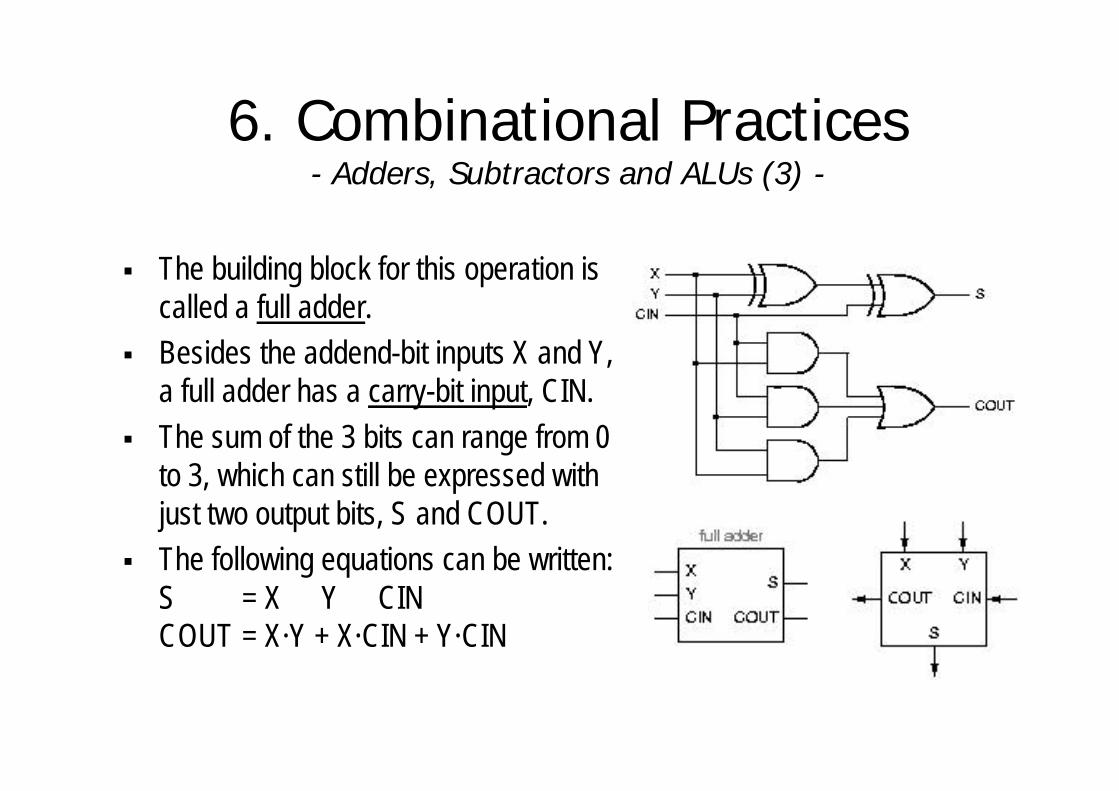
§ The building block for this operation is called a full adder.
§ Besides the addend-bit inputs X and Y, a full adder has a carry-bit input, CIN.
§ The sum of the 3 bits can range from 0 to 3, which can still be expressed with just two output bits, S and COUT.
§ The following equations can be written:S = X ⊕ Y ⊕ CIN COUT = X·Y + X·CIN + Y·CIN
6. Combinational Practices- Adders, Subtractors and ALUs (4) -
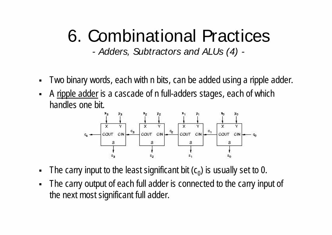
§ Two binary words, each with n bits, can be added using a ripple adder.§ A ripple adder is a cascade of n full-adders stages, each of which
handles one bit.
§ The carry input to the least significant bit (c0) is usually set to 0.§ The carry output of each full adder is connected to the carry input of
the next most significant full adder.
6. Combinational Practices- Adders, Subtractors and ALUs (5) -
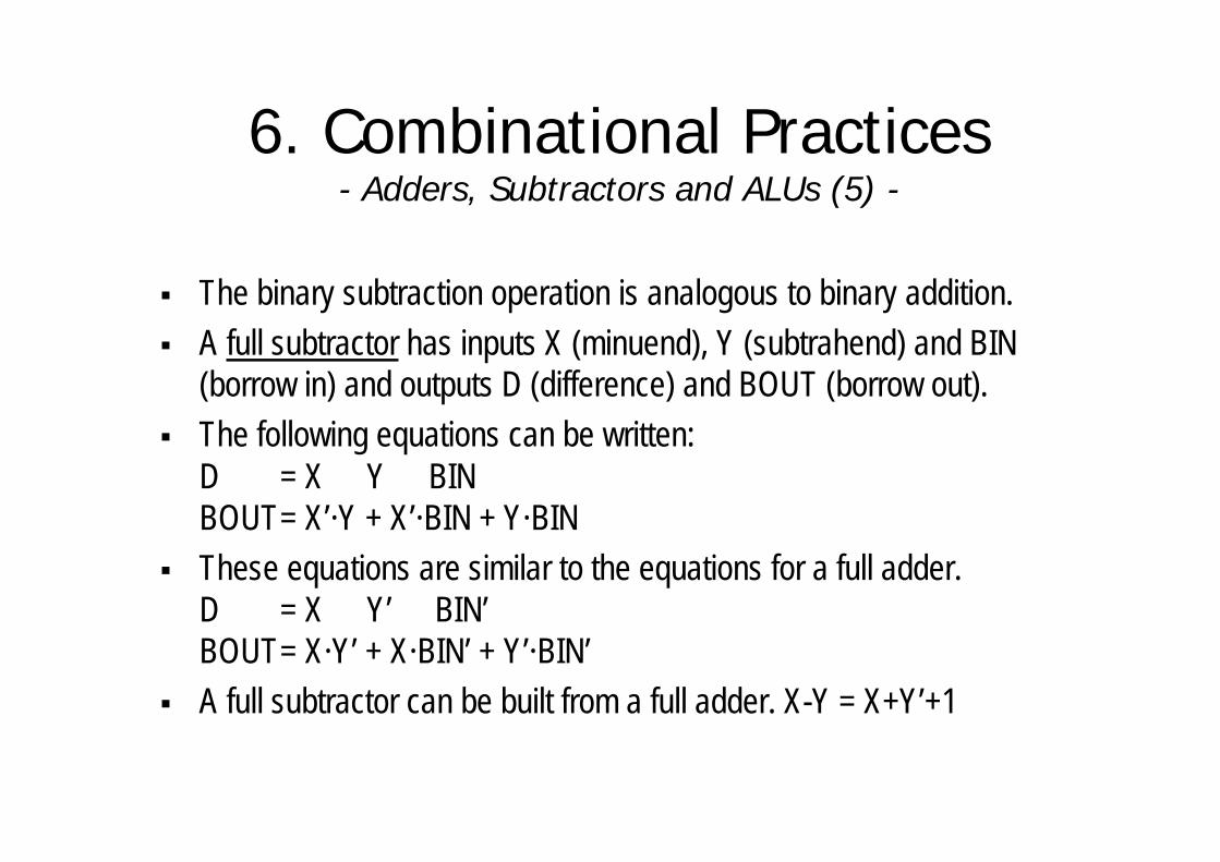
§ The binary subtraction operation is analogous to binary addition.§ A full subtractor has inputs X (minuend), Y (subtrahend) and BIN
(borrow in) and outputs D (difference) and BOUT (borrow out).§ The following equations can be written:
D = X ⊕ Y ⊕ BIN BOUT= X’·Y + X’·BIN + Y·BIN
§ These equations are similar to the equations for a full adder.D = X ⊕ Y’ ⊕ BIN’ BOUT= X·Y’ + X·BIN’ + Y’·BIN’
§ A full subtractor can be built from a full adder. X-Y = X+Y’+1
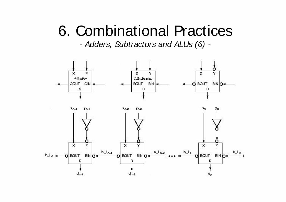
6. Combinational Practices- Adders, Subtractors and ALUs (6) -

6. Combinational Practices- Adders, Subtractors and ALUs (7) -
§ An ALU is a combinational circuit that can perform several arithmetic and logical operations on a pair of b-bit operands.
§ The operation to be performed is specified by a set of function-select inputs.
§ Typical MSI ALUs have 4-bit operands and three to five function-select inputs, allowing up to 32 different functions to be performed.
§ A 74x181 IC has one 4-bit ALU.§ The operation performed by the 74x181 is selected
by the M and S3-S0 inputs.
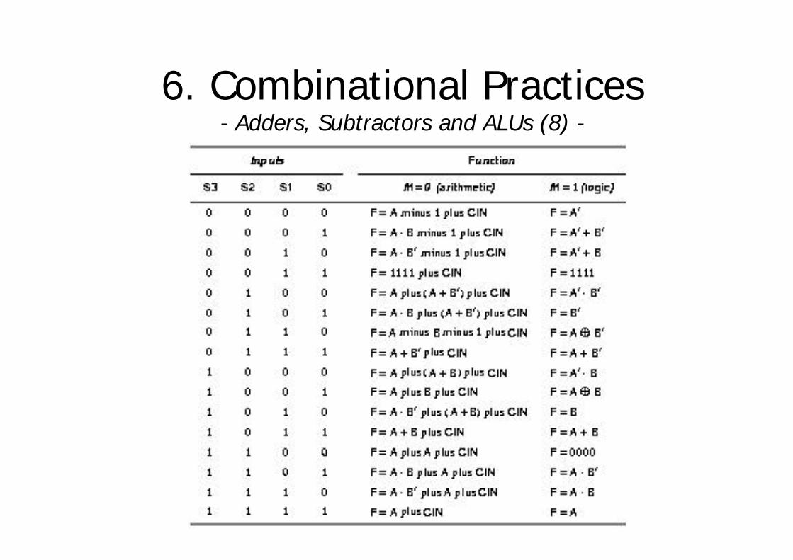
6. Combinational Practices- Adders, Subtractors and ALUs (8) -
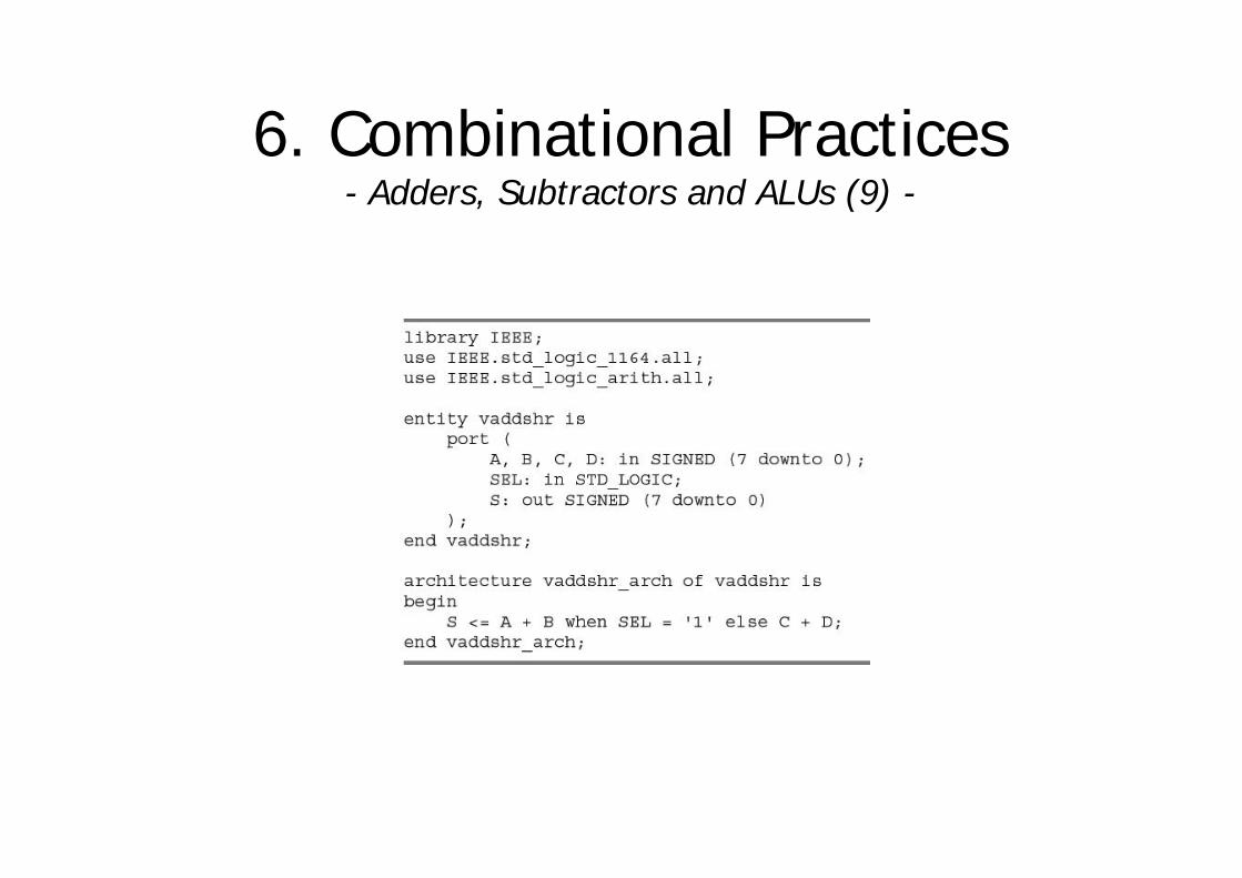
6. Combinational Practices- Adders, Subtractors and ALUs (9) -

6. Combinational Practices- Multipliers (1) -
§ The traditional algorithm to multiply binary numbers uses shifts and adds to obtain the result.
§ However, it is not the only solution to implement a multiplier. § Given 2 n-bit inputs (X, Y), we can write a truth table that expresses
the 2n-bit product P=X×Y as a combinational function of X and Y.§ Most approaches to combinational multipliers are based on the
traditional shift-and-add algorithm.
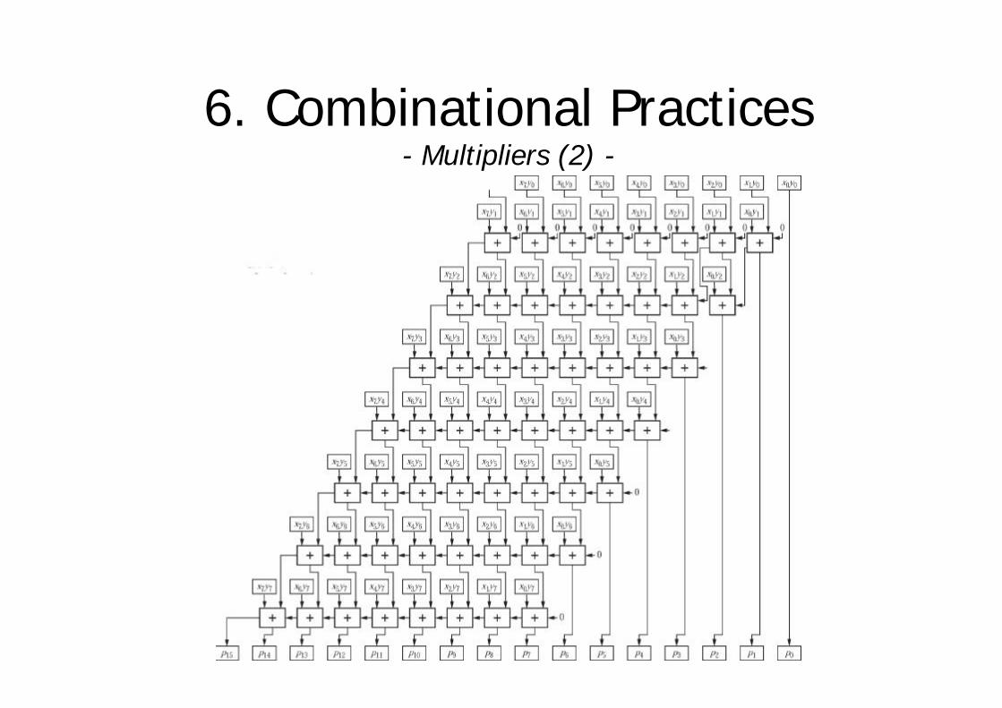
6. Combinational Practices- Multipliers (2) -

6. Combinational Practices- Multipliers (3) -


