SITE EVALUATION FOR SUBSURFACE WASTEWATER DISPOSAL DESIGN IN MAINE Maine Department of Human Services, Bureau of Health, Division of Health Engineering Revised April, 2001 Third Edition Appropriation 014-10A-2426-012-2658 Nondiscrimination Notice In accordance with Title VI of the Civil Rights Act of 1964, as amended by the civil Rights Restoration Act of 1991 (42 U.S.C. 1981, 2000e et seq.) Section 504 of the Rehabilitation Act of 1973, as amended (29 U.S.C. 794), the Age Discrimination Act of 1975, as amended (42 U.S.C. 6101 et seq.), Title II of the Americans with Disabilities Act of 1990 (42 U.S.C. 12101 et seq.), and Title IX of the Education Amendments of 1972, the Maine Department of Human Services does not discriminate on t he basis of sex, color, national origin, disability or age in admission or access to or treatment or employment in its programs and activities
Transcript
SITE EVALUATION
FOR
SUBSURFACE WASTEWATER DISPOSAL
DESIGN IN MAINE
Maine Department of Human Services, Bureau of Health,
Division of Health Engineering
Revised April, 2001
Third Edition
Appropriation 014-10A-2426-012-2658
Nondiscrimination Notice
In accordance with Title VI of the Civil Rights Act of 1964, as amended by the civil Rights Restoration Act of 1991 (42 U.S.C. 1981, 2000e et seq.) Section 504 of the Rehabilitation Act of 1973, as amended (29 U.S.C. 794),
the Age Discrimination Act of 1975, as amended (42 U.S.C. 6101 et seq.), Title II of the Americans with Disabilities Act of 1990 (42 U.S.C. 12101 et seq.), and Title IX of the Education Amendments of 1972, the Maine Department of Human Services does not discriminate on the basis of sex, color, national origin, disability or
age in admission or access to or treatment or employment in its programs and activities
SITE EVALUATION FOR SUBSURFACE WASTEWATER DISPOSAL DESIGN IN MAINE
i
ACKNOWLEDGMENTS
Maine’s Department of Human Services, Division of Health Engineering is responsible for administering the Subsurface Wastewater Disposal Rules which regulates the design and installation of subsurface wastewater disposal systems. Minimum standards are established to protect the public health, safety and welfare. A site evaluation is required prior to siting and designing a subsurface wastewater disposal system. Rules have been established for the purpose of maintaining a standard of professionalism in the Site Evaluation Program. This material is presented as an educational manual for exp laining the principles and concepts of Site Evaluation. Principal Author Albert Frick, Soil Scientist, formerly of Division of Health Engineering Author appreciates assistance from: Donald Hoxie, formerly of Division of Health Engineering Revisers April, 2001 Dina LaFlamme, Division of Health Engineering James Jacobsen, Division of Health Engineering Reviewers, April, 2001 Linda Robinson, Division of Health Engineering Jay Hardcastle, Division of Health Engineering David Rocque, State Soil Scientist
SITE EVALUATION FOR SUBSURFACE WASTEWATER DISPOSAL DESIGN IN MAINE
ii
TABLE OF CONTENTS PAGE INTRODUCTION 1 I. SUBSURFACE WASTEWATER DISPOSAL DESIGN 2 Domestic Wastewater Effluent 2 Subsurface Wastewater Disposal System 2 Building Sewer 2 Treatment Tank 3 Effluent Sewer 4 Distribution Box 5 Disposal Areas 5 Bed Disposal Area 6 Trench Disposal Area 8 Proprietary Disposal Devices 10 Background 10 Disposal Chambers 11 Sizing 12 Plastic Chambers 13 Gravel- less Trenches: Fabric Covered Tubes 16 Gravel- less Beds: Cuspated Blocks 18 Drip Irrigation 19 Drip Irrigation: Soaker Hoses 19 Drip Irrigation: Drip Emitters 20 Septic Tank Effluent Filters 21 Effluent Polishing Filters 21 Peat Filters 21 Sand Filters 22 Graduated Media Filters 23 Septic Tank Filters 24 Whole Tank Filters 25 Advanced Wastewater Treatment Units 26 Aerobic Treatment Units 26 Fixed Film Aerobic Treatment Units 27 Recirculating Aerobic Treatment Units 28 Microwave Treatment 29 Pumping 30 Dosing 30 II. SITE EVALUATION 32 Location of the Parcel of Land 32 Arrangements and Agreements 32 Size of Lot 32 Type of Proposed Development and Size 32 Preliminary Concepts 33
SITE EVALUATION FOR SUBSURFACE WASTEWATER DISPOSAL DESIGN IN MAINE
iii
Zoning and Local Ordinances 33 Easements or Special Considerations 33 Minimum Lot Size Law 33 Location of Water Bodies 33 Slope of Terrain 33 Surface Drainage 34 Water Supply 34 Native Vegetation 34 Terrain and Positions in Landscape 34 Flood Plains 34 Bedrock Outcropping 34 Elevation Reference Point 35 Land Use 35 Professional Statement of Adequate Disposal Systems 35 Location of Observation Holes 39 Log of Soil Profile 39 Public Relations 39 Design and Field Layout 39
III SOIL EVALUATION 41 Soil Profiles 43 Soil Formation 44 Soil Texture 45 Soil Parent Material 48 Glacial Till 49 Stratified Drift Deposit 45 Marine Sediment 52 Lacustrine Deposits 53 Alluvial Deposits 53 Organic Deposits 55 Soil Wetness 55 Soil Drainage Classes 55 Soil Color 56 Soil Drainage Mottles 57 Position in Landscape and Soil Characteristics 58 Soil Structure 59 Consistence 60 Restrictive Layer 61 Classification of Soils 61
SITE EVALUATION FOR SUBSURFACE WASTEWATER DISPOSAL DESIGN IN MAINE
iv
IV. COMPLETION OF APPLICATION FOR SUBSURFACE
WASTEWATER DISPOSAL PERMIT (HHE-200 FORM) 64 V. SPECIAL CONSIDERATIONS 83 Variances to the Subsurface Wastewater Disposal Rules 83 Replacement System Variance 83 First Time System Variance 84 Flood Plain Siting 84 Coastal Sand Dune 86 Cluster Systems 95 Malfunctioning Systems, Troubleshooting and Remedies 96 Identification 96 Remediation 98 Septic Tank Additives 100 Chemical Rejuvenation 100 VI. GLOSSARY OF TERMS 101 VII. BIBLIOGRAPHY 102
SITE EVALUATION FOR SUBSURFACE WASTEWATER DISPOSAL DESIGN IN MAINE
v
LIST OF FIGURES Page
Figure 1. Essential features of a disposal system 3
Figure 2. Cross-section of a typical septic tank 4
Figure 3. Distribution box 5
Figure 4. Cross-section of disposal bed 7
Figure 5. Stone layer of disposal bed during construction 8
Figure 6. Trench system during construction 9
Figure 7. Comparison of Vee-plank and tile trenches 10
Figure 8. Chamber system during construction 11
Figure 9. Perspective of a chamber 12
Figure 10. Manufactured chamber designs and distribution methods 13
Figure 11. Plastic chamber installation showing exposed sidewall and back fill 14
Figure 12. Plastic chamber installation showing interior and established biomat 14
Figure 13. A narrow trench configuration plastic chamber. 15
Figure 14. Cross section of fabric covered tube. 16
Figure 15. Fabric covered tube installation. 17
Figure 16. Fabric covered tubes installed for serial distribution. 17
Figure 17. A display sample of a cuspated block 18
Figure 18. Installation of a cuspated block gravel- less beds 19
Figure 19. Porous soaker hose drip irrigation system 20
Figure 20. Drip irrigation line and emitter 20
Figure 21. Simplified cross section of a peat filter module 21
Figure 22. Cross section of under-drained sand filter 22
Figure 23. Isometric cross section of graduated media filter 23
Figure 24. Residential septic tank outlet filters 24
Figure 25. Commercial/industrial septic tank outlet filters 24
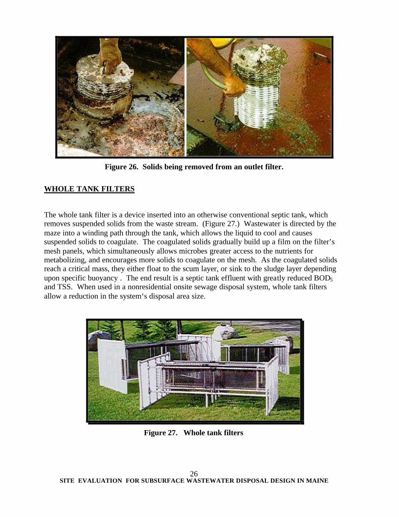
Figure 26. Solids being removed from an outlet filter 25
Figure 27. Whole tank filters 25
Figure 28. Simplified cross section of an aerobic treatment tank 26
Figure 29. Simplified cross section of an aerobic-fixed film treatment tank 29
Figure 30. Simplified cross section of a recirculating aerobic treatment tank 28
Figure 31. Typical microwave residential system 29
SITE EVALUATION FOR SUBSURFACE WASTEWATER DISPOSAL DESIGN IN MAINE
vi
Figure 32. Effluent and sewage lift station design layouts 31
Figure 33. Pump tank and effluent pump for single family residence 31
Figure 34. Examples of harmonious and inharmonious sitings of
disposal systems and wells 36,37
Figure 35. Position in landscape 38
Figure 36. Flood plain 38
Figure 37. Test pit excavated with a backhoe to a depth of four feet 39
Figure 38. Components of soil 41
Figure 39. Theoretical soil horizonation 42
Figure 40. Typical soil profiles 45
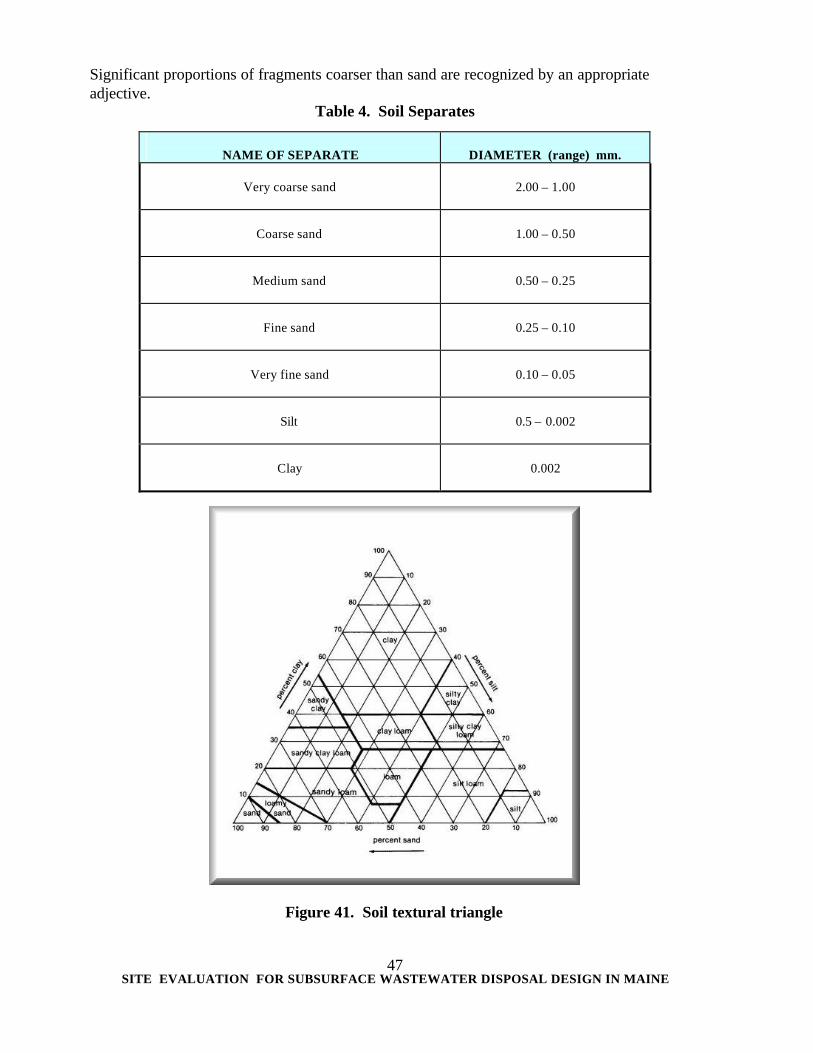
Figure 41. Soil textural triangle 46
Figure 42. Silty clay soil ribboning 48
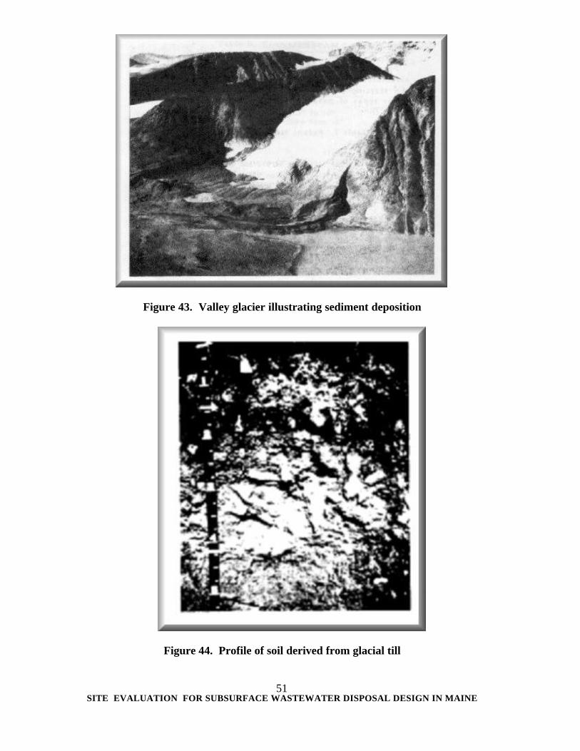
Figure 43. Valley glacier illustrating sediment deposited directly by ice mass 50
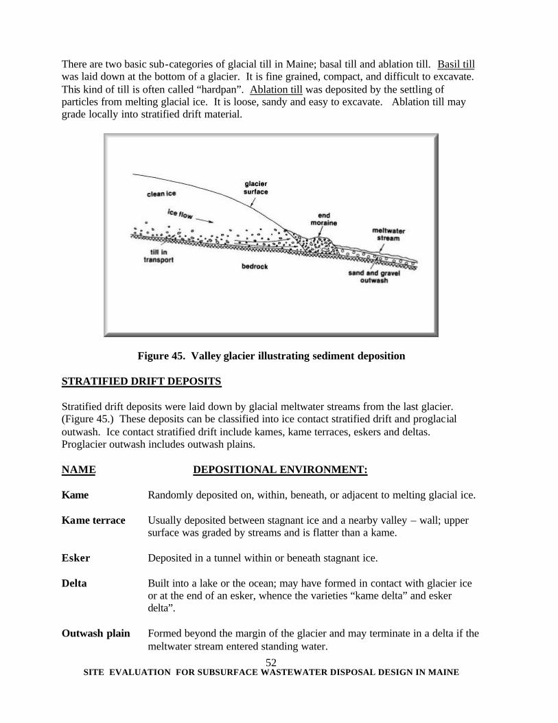
Figure 44. Profile of a soil derived from glacial till 50
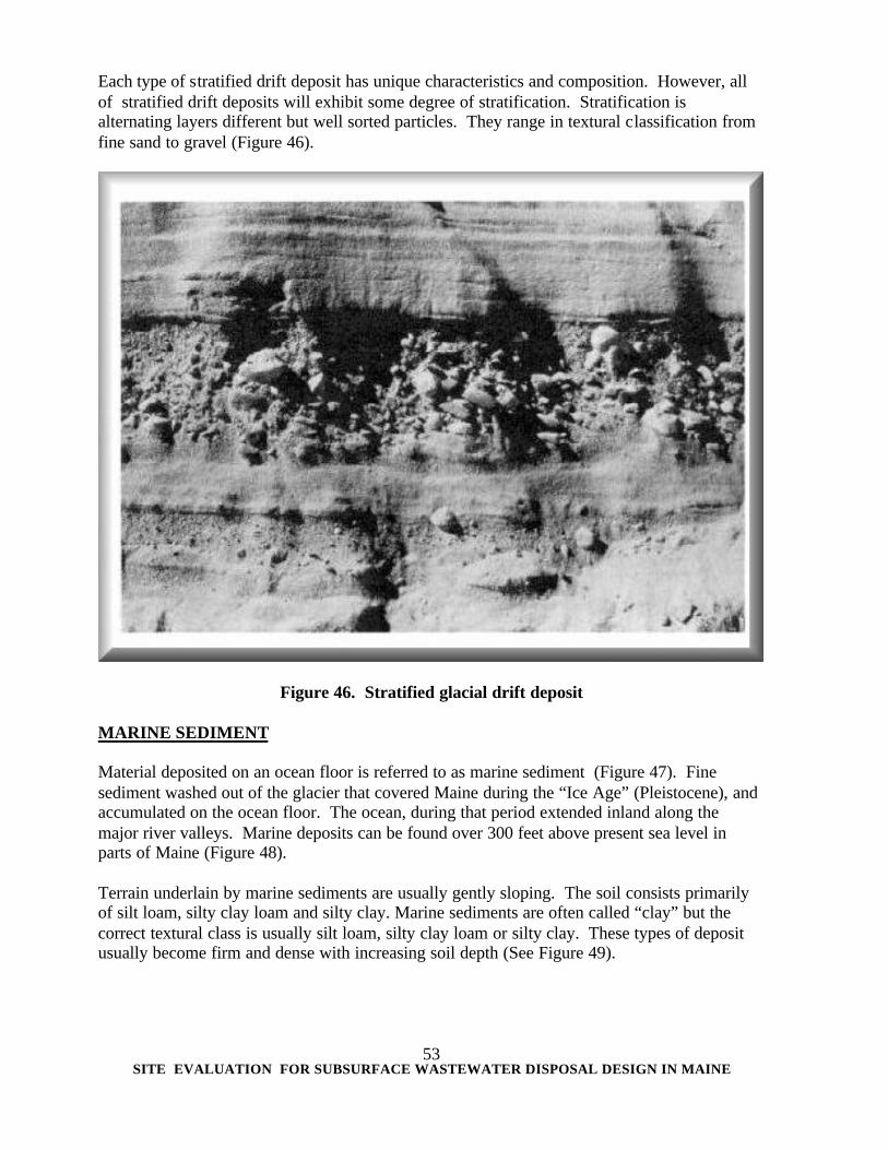
Figure 45. Valley glacier illustrating sediment deposition 51
Figure 46. Stratified drift deposit 52
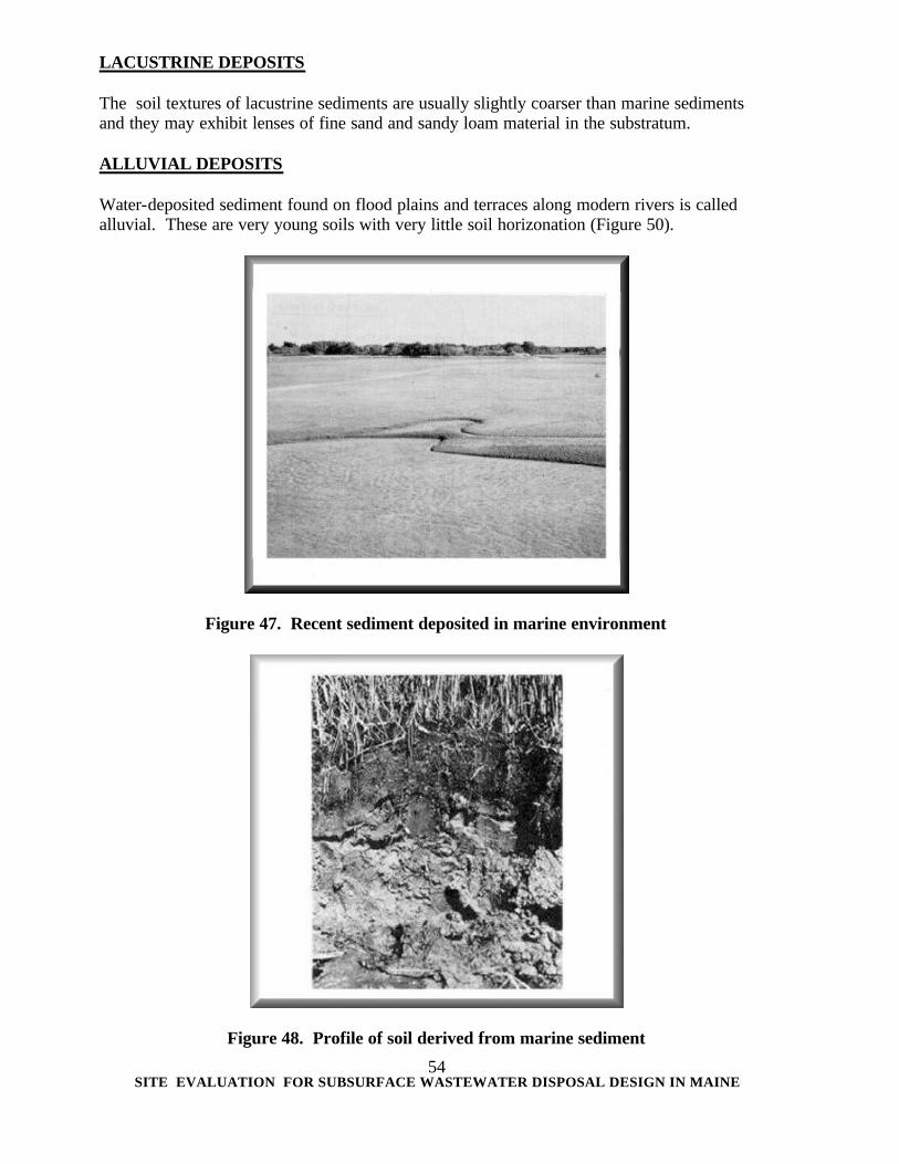
Figure 47. Recent sediment deposited in marine environment 53
Figure 48. Profile of soil derived from marine sediment 53
Figure 49. Extent of glacial-marine clay in Maine 54
Figure 50. Cross-section showing relationships among surficial deposits 54
Figure 51. Soil drainage and ground water table 59
Figure 52. Soil structure 60
Figure 53. Top view of prismatic structure in a subsoil 61
Figure 54. Natural drainage classes of soils and subsurface wastewater disposal classification 63
Figure 55. Distribution of copies of the Application 64
Figure 56. Application for on-site Wastewater Disposal System
(HHE-200 Form, Page 1) 65
Figure 57. Application for on-site Wastewater Disposal System
(HHE-200 Form Page 2) 66
Figure 58. Application for on-site Wastewater Disposal System
(HHE-200 Form Page 3) 67
Figure 59. Replacement System Variance Request (Page 1) 79
SITE EVALUATION FOR SUBSURFACE WASTEWATER DISPOSAL DESIGN IN MAINE
vii
Figure 60. Replacement System Variance Request (Page 2) 80
Figure 61. First Time System Variance Request (Page 1) 81
Figure 62. New System Variance Request (Page 2) 82
Figure 63. Flood Boundary, Floodway Map 85
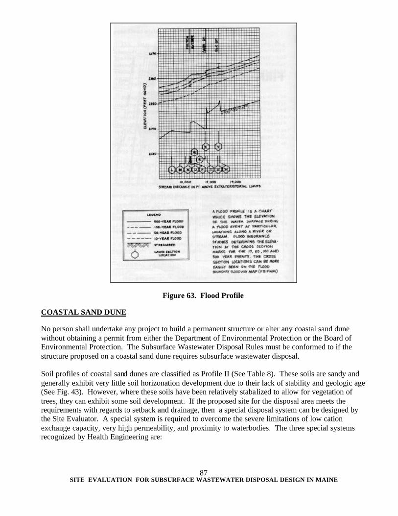
Figure 64. Flood Profile 86
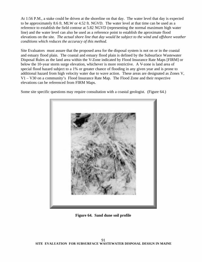
Figure 65. Sand dune soil profile 91
Figure 66. Cluster systems 95
Figure 67. Malfunction resulting in effluent breakout and overland runoff 97
Figure 68. Malfunction resulting in effluent breakout and ponding 98
Figure 69. Malfunction resulting in effluent runoff and breakout 99
Figure 70. Malfunction resulting in a chronic wet area 99
SITE EVALUATION FOR SUBSURFACE WASTEWATER DISPOSAL DESIGN IN MAINE
viii
LIST OF TABLES PAGE
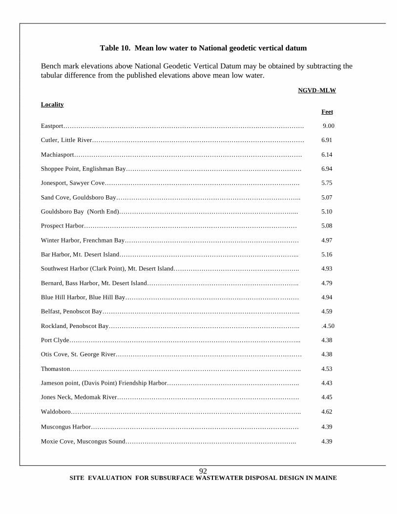
Table 1. Sizing of disposal beds 7 Table 2. Sizing of trenches 9 Table 3. Sizing of chamber systems 12 Table 4. Soil separates 46 Table 5. Feelings and appearance of various soil textural classes 47 Table 6. Coarse fragments 48 Table 7. Parent materials in Maine 49 Table 8. Soil profile & condition versus system sizes in Maine 62 Table 9. Soil, site and engineering and factors used in assessing potentials for A New System Variance. 88, 89 Table 10. Means low water to National geodetic vertical datum 91, 92 Table 11. Tidal differences and other constants, 1983 93 Table 12. Time and heights of high and low waters, Portland, ME, 1983 94
SITE EVALUATION FOR SUBSURFACE WASTEWATER DISPOSAL DESIGN IN MAINE
1
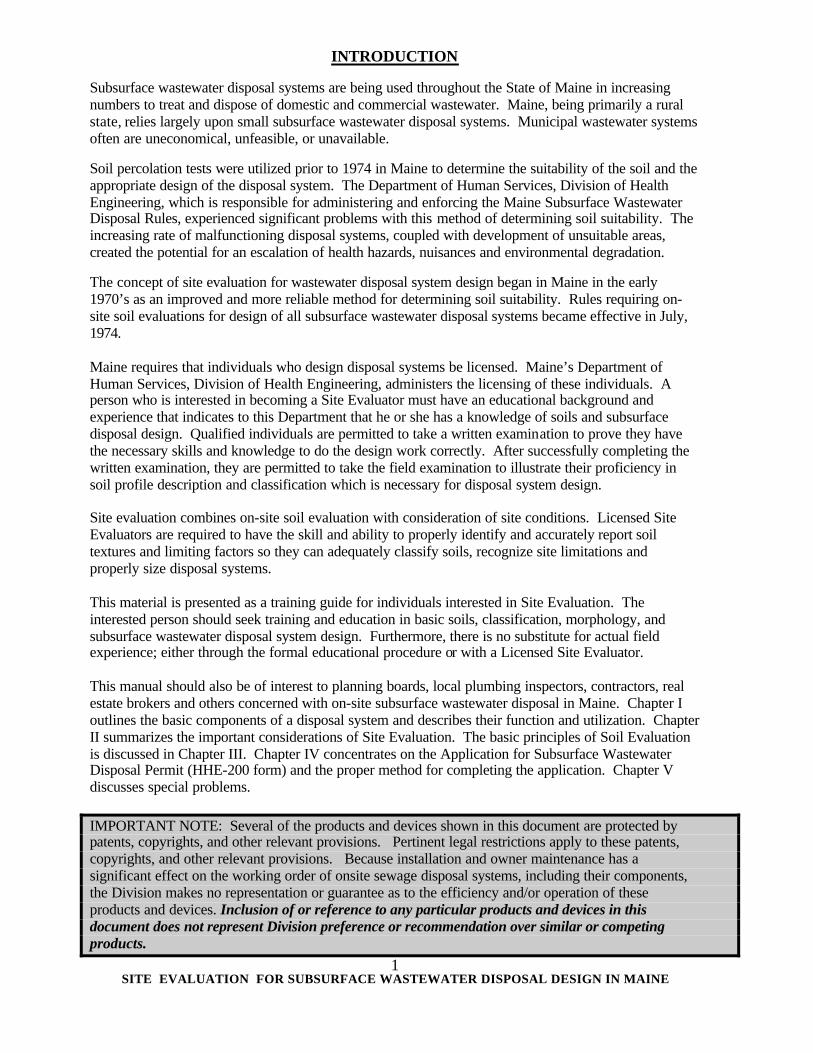
INTRODUCTION
Subsurface wastewater disposal systems are being used throughout the State of Maine in increasing numbers to treat and dispose of domestic and commercial wastewater. Maine, being primarily a rural state, relies largely upon small subsurface wastewater disposal systems. Municipal wastewater systems often are uneconomical, unfeasible, or unavailable. Soil percolation tests were utilized prior to 1974 in Maine to determine the suitability of the soil and the appropriate design of the disposal system. The Department of Human Services, Division of Health Engineering, which is responsible for administering and enforcing the Maine Subsurface Wastewater Disposal Rules, experienced significant problems with this method of determining soil suitability. The increasing rate of malfunctioning disposal systems, coupled with development of unsuitable areas, created the potential for an escalation of health hazards, nuisances and environmental degradation. The concept of site evaluation for wastewater disposal system design began in Maine in the early 1970’s as an improved and more reliable method for determining soil suitability. Rules requiring on-site soil evaluations for design of all subsurface wastewater disposal systems became effective in July, 1974. Maine requires that individuals who design disposal systems be licensed. Maine’s Department of Human Services, Division of Health Engineering, administers the licensing of these individuals. A person who is interested in becoming a Site Evaluator must have an educational background and experience that indicates to this Department that he or she has a knowledge of soils and subsurface disposal design. Qualified individuals are permitted to take a written examination to prove they have the necessary skills and knowledge to do the design work correctly. After successfully completing the written examination, they are permitted to take the field examination to illustrate their proficiency in soil profile description and classification which is necessary for disposal system design. Site evaluation combines on-site soil evaluation with consideration of site conditions. Licensed Site Evaluators are required to have the skill and ability to properly identify and accurately report soil textures and limiting factors so they can adequately classify soils, recognize site limitations and properly size disposal systems. This material is presented as a training guide for individuals interested in Site Evaluation. The interested person should seek training and education in basic soils, classification, morphology, and subsurface wastewater disposal system design. Furthermore, there is no substitute for actual field experience; either through the formal educational procedure or with a Licensed Site Evaluator. This manual should also be of interest to planning boards, local plumbing inspectors, contractors, real estate brokers and others concerned with on-site subsurface wastewater disposal in Maine. Chapter I outlines the basic components of a disposal system and describes their function and utilization. Chapter II summarizes the important considerations of Site Evaluation. The basic principles of Soil Evaluation is discussed in Chapter III. Chapter IV concentrates on the Application for Subsurface Wastewater Disposal Permit (HHE-200 form) and the proper method for completing the application. Chapter V discusses special problems. IMPORTANT NOTE: Several of the products and devices shown in this document are protected by patents, copyrights, and other relevant provisions. Pertinent legal restrictions apply to these patents, copyrights, and other relevant provisions. Because installation and owner maintenance has a significant effect on the working order of onsite sewage disposal systems, including their components, the Division makes no representation or guarantee as to the efficiency and/or operation of these products and devices. Inclusion of or reference to any particular products and devices in this document does not represent Division preference or recommendation over similar or competing products.
SITE EVALUATION FOR SUBSURFACE WASTEWATER DISPOSAL DESIGN IN MAINE
2
I. SUBSURFACE WASTEWATER DISPOSAL DESIGN DOMESTIC WASTEWATER EFFLUENT Normal household wastewater consists of all the liquid household waste which is generated from the toilet, bath, kitchen and laundry. This material is composed of about 99.9 percent liquids and about 0.1 percent solids. The small percentage of solids and the microorganisms in wastewater are the cause of health hazards and nuisances. Approximately two-thirds of the solids in domestic wastewater are organic compounds, primarily carbohydrates and fats. The organic compounds are the primary source of odors and nuisances, requiring large volumes of oxygen to render them stable, inoffensive and non-hazardous. Other substances in wastewater that are undesirable and potentially harmful are: pathogenic bacteria, infectious viruses, organic matter, toxic chemicals , and excess nutrients, such as nitrogen and phosphorus. These substances would create public health hazards, nuisances, and pollution problems if not properly treated. The specifications in the Subsurface Wastewater Disposal Rules for calculating the size of wastewater disposal fields assume that the waste being treated is of the same quality as normal household wastewater. When it is suspected that the wastewater to be treated is different than domestic wastewater, the suspended solids and biochemical oxygen demand should be measured and considered for adjusting the disposal field size. If the waste is a by-product of any textile, printing furniture stripping, metal plating, paint, manufacturing, pharma-ceutical, pesticide, petroleum, leather, rubber or plastic manufacturing, then the application for the disposal system should be directed t o the Department of Environmental Protection. SUBSURFACE WASTEWATER DISPOSAL SYSTEM A properly functioning system is one which will not allow harmful pollutants to accumulate to dangerous levels in the environment. The essential features of a typical system are the building sewer, treatment tank, effluent sewer, distribution line, disposal field, and surrounding soil (Figure 1). Many disposal systems also include a distribution box or a pumping chamber. BUILDING SEWER The building sewer is a water tight pipeline which is used to convey the raw wastewater to the treatment tank. It should extend a minimum of 8 feet from the building foundation to allow for ease of installation of the treatment tank. It is also good practice, in designing disposal systems, to keep the length of the building sewer as short in length as practical in order to reduce the probability of blockage and to facilitate cleaning of the sewer line if it should become blocked.
SITE EVALUATION FOR SUBSURFACE WASTEWATER DISPOSAL DESIGN IN MAINE
3
Figure 1. Essential features of a disposal system. TREATMENT TANK The treatment tank functions as a conditioning device and provides for primary treatment of the wastewater. The raw wastewater is detained in the treatment tank long enough for it to be rendered more suitable for discharge to the disposal area. If the raw wastewater were discharged directly to the disposal area, the pore spaces between the soil particles would quickly become clogged by the solid materials contained in the wastewater. Wastewater that does not percolate between the soil particles either backs up through the plumbing system into the house or comes to the surface of the ground near the disposal area. To minimize the likelihood of this occurrence, the raw wastewater is held for a period of one to three days in the treatment tank where it is subjected to a combination of physical, chemical and biological actions which result in the conversion of most of the solid materials to liquids and gases. The gases either escape through the house plumbing vent or mix with the effluent, and the clarified liquid is channeled to the disposal field. Some of the solids remain in the tank as sludge or scum and must be removed periodically before they accumulate to the point where they will be carried over into the disposal field. Pumping of the treatment tank every 3 to 4 years is generally considered to be of good maintenance practice. Some treatment tanks may need to be pumped more frequently, depending on quality of the wastewater. The total solids in wastewater consist of dissolved or soluble solids, suspended or colloidal solids, and settleable solids. The dissolved and suspended solids remain in the wastewater and do not settle out, while the settleable solids are removed from the wastewater by gravity if allowed sufficient time. Primary treatment, which takes place in the treatment tank, is a settling process in which the settleable solids sink to the bottom by gravitation. Certain materials in the wastewater, known as scum and consisting of paper, grease, and similar constituents lighter than the liquid wastewater will rise to the top. These materials are prevented from entering the disposal area by baffles designed to trap the floatable substances in the treatment tank.
SITE EVALUATION FOR SUBSURFACE WASTEWATER DISPOSAL DESIGN IN MAINE
4
There are two types of treatment tanks recognized for use in Maine: septic tank and aerobic tank. Septic tanks produce an anaerobic environment and rely on anaerobic bacteria for treatment (Figure 2). Aerobic tanks pump fresh air into the tank and rely on aerobic bacteria for treatment. The bacteria in aerobic treatment tanks, although more active, are also more sensitive and fragile to fluctuating conditions than an anaerobic bacteria in septic tanks. Aerobic treatment tanks are relatively more expensive, require maintenance, and need an energy source.
Figure 2. Cross-section of a typical septic tank. Treatment tanks must be sited in areas where they will not be subject to either surface water or ground water infiltration. The treatment tank outlet should be above the seasonal high ground water table to prevent ground water entering the tank. EFFLUENT SEWER The effluent line is a water tight pipeline which conveys the treatment tank effluent to the disposal area. Flow is usually by gravity but may be pumped in certain instances. There should be a drop in elevation between the treatment tank and disposal field of 1/8 inch per foot or more with a gravity effluent line. This drop is to prevent a sluggish disposal area or one exposed to large peak flows from backing up during periods of stress and causing the liquid level in the septic tank from rising above the baffles. The greater the elevation drop between the septic tank outlet and the disposal field, the lower the possibility of solids reaching the disposal field by flowing over a conventional septic tank baffle during stress periods.
SITE EVALUATION FOR SUBSURFACE WASTEWATER DISPOSAL DESIGN IN MAINE
5
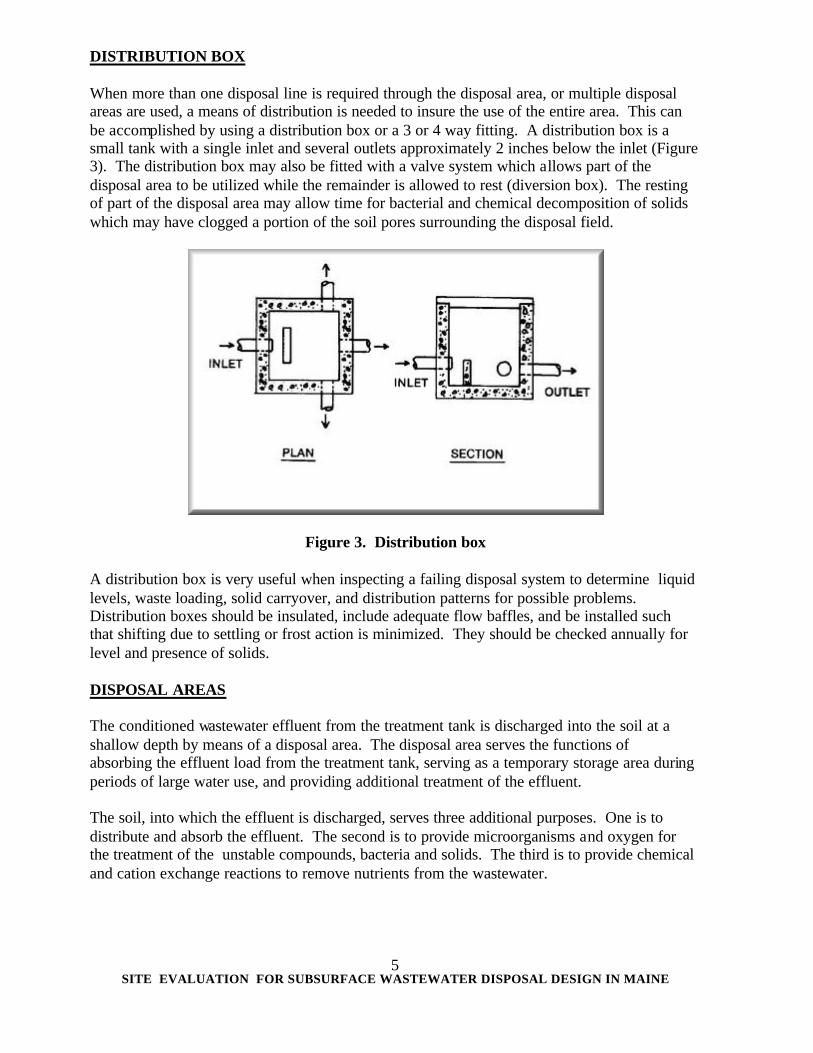
DISTRIBUTION BOX When more than one disposal line is required through the disposal area, or multiple disposal areas are used, a means of distribution is needed to insure the use of the entire area. This can be accomplished by using a distribution box or a 3 or 4 way fitting. A distribution box is a small tank with a single inlet and several outlets approximately 2 inches below the inlet (Figure 3). The distribution box may also be fitted with a valve system which allows part of the disposal area to be utilized while the remainder is allowed to rest (diversion box). The resting of part of the disposal area may allow time for bacterial and chemical decomposition of solids which may have clogged a portion of the soil pores surrounding the disposal field.
Figure 3. Distribution box
A distribution box is very useful when inspecting a failing disposal system to determine liquid levels, waste loading, solid carryover, and distribution patterns for possible problems. Distribution boxes should be insulated, include adequate flow baffles, and be installed such that shifting due to settling or frost action is minimized. They should be checked annually for level and presence of solids. DISPOSAL AREAS The conditioned wastewater effluent from the treatment tank is discharged into the soil at a shallow depth by means of a disposal area. The disposal area serves the functions of absorbing the effluent load from the treatment tank, serving as a temporary storage area during periods of large water use, and providing additional treatment of the effluent. The soil, into which the effluent is discharged, serves three additional purposes. One is to distribute and absorb the effluent. The second is to provide microorganisms and oxygen for the treatment of the unstable compounds, bacteria and solids. The third is to provide chemical and cation exchange reactions to remove nutrients from the wastewater.
SITE EVALUATION FOR SUBSURFACE WASTEWATER DISPOSAL DESIGN IN MAINE
6
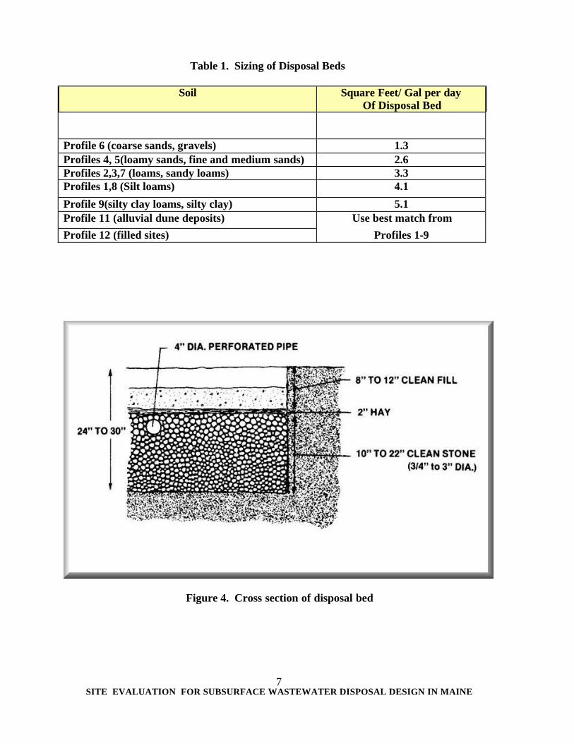
Disposal of liquids into the soil from a disposal area is through soil pores, between soil aggregates and through root channels. The soil pores vary in size with soil texture. Soil texture, soil structure, moisture content, and root penetration also effect the liquid movement through the soil. The size of the soil pores influence the permeability rate which in turn determines the amount of wastewater the soil can absorb. Soils with very fine textures (silts and silty clay) can absorb effluent only at a very slow rate, while sandy soils with coarse textures can absorb larger quantities of effluent. The texture of the soil is an important factor in determining the suitability of a particular soil for wastewater disposal. The liquid movement from a disposal area into the surrounding soil is by gravitational and hydrostatic pressure as well as capillary or matrix tension. Coarse textured soils (sands, or loamy sands) rely on the large pores for water movement and are primarily influenced by gravitational pressure. Finer textured soils (silt loams, silts, silty clay loams) mostly depend on the smaller capillary pores for water movement. In small pores, capillary attraction tends to retard the pull of gravity and slow the percolation rate. Only in the larger soil pores does the water move with any degree of speed. The effluent, when it exits the septic tank is anaerobic, it is only partially treated and contains many solids as well as numerous facultative and anaerobic bacteria and unstable compounds. Effluent from the septic tank must be treated aerobically before complete treatment is obtained. The effluent moving into the soil area contains anaerobic bacteria and viruses. The population of these organisms can be reduced by the creation of an unfavorable environment in the surrounding soil media. Physical filtration of bacteria and viruses is not very practical due to their size relative to the size of soil pores. Filtration of the organic matter at the soil interface tends to restrict the food supply of bacteria. Aeration of the wastewater as it moves through the soil tends to create an environment hazardous to the survival of the organisms. The soil may also contain some organisms that are toxic to the bacteria and viruses. Wastewater entering directly into a seasonal water table does not have adequate treatment other than dilution. The regulations require that a proper separation distance between the bottom of the disposal field and the seasonal high ground water table be maintained to assure adequate treatment by providing a zone of aeration. A properly designed disposal system must be properly sited to provide for adequate treatment and disposal of the wastewater. Failure to meet all necessary design criteria introduces a greater probability of failure and higher risk of creating a potential health or environmental hazard. BED DISPOSAL AREA A disposal area acts as an underground retention area. Stone (3/4 to 2 1/2 inches in diameter) is used in the construction of a bed to provide void space for the storage of effluent and to allow it to drain slowly through the soil. (See Fig. 4 and Fig. 5.) The disposal bed size is calculated by multiplying the expected volume of wastewater expressed in gallons per day by the size rating parameter determined by the soil evaluation. Table l indicates the required size rating and hydraulic loading rate for disposal beds.
SITE EVALUATION FOR SUBSURFACE WASTEWATER DISPOSAL DESIGN IN MAINE
7
Table 1. Sizing of Disposal Beds
Soil Square Feet/ Gal per day Of Disposal Bed
Profile 6 (coarse sands, gravels) 1.3 Profiles 4, 5(loamy sands, fine and medium sands) 2.6 Profiles 2,3,7 (loams, sandy loams) 3.3 Profiles 1,8 (Silt loams) 4.1
Profile 9(silty clay loams, silty clay) 5.1 Profile 11 (alluvial dune deposits) Use best match from Profile 12 (filled sites) Profiles 1-9
Figure 4. Cross section of disposal bed
SITE EVALUATION FOR SUBSURFACE WASTEWATER DISPOSAL DESIGN IN MAINE
8
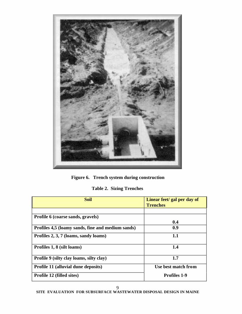
Figure 5. Stone layer of disposal bed during construction Bed widths may vary from 4 feet wide to 20 feet wide. Narrow beds are more advantageous than wide beds because they increase the sidewall area relative to the bottom area which promotes longevity of the disposal area. Narrow beds should be considered first for placement on steeper slopes because they reduce the amount of fill required on the downslope side. The advantages of wide beds are that they are more easily installed with mechanical equipment and require less over-all area for installation than narrow beds. TRENCH DISPOSAL AREA A trench disposal area is approximately 2 to 3 feet wide and constructed of the same materials as the bed disposal area. (Figure 6.) The trench system is only practical on well drained sites and most often used in stratified drift sediments (Profile 5 and 6 soils). The trench disposal area is also more labor intensive than the bed disposal area since it is not as easily suited to mechanized construction; requiring more backhoe time and manual labor. The trench stone layer must be 12 inches deep to conform to the sizing criteria of Table 2. Any increase in trench depth must be upward, that is, the increased trench depth can not compromise the separation distance from the limiting factor.
SITE EVALUATION FOR SUBSURFACE WASTEWATER DISPOSAL DESIGN IN MAINE
9
Figure 6. Trench system during construction
Table 2. Sizing Trenches
Soil Linear feet/ gal per day of Trenches
Profile 6 (coarse sands, gravels)
0.4
Profiles 4,5 (loamy sands, fine and medium sands) 0.9
Profiles 2, 3, 7 (loams, sandy loams) 1.1
Profiles 1, 8 (silt loams) 1.4
Profile 9 (silty clay loams, silty clay) 1.7
Profile 11 (alluvial dune deposits) Use best match from
Profile 12 (filled sites) Profiles 1-9
SITE EVALUATION FOR SUBSURFACE WASTEWATER DISPOSAL DESIGN IN MAINE
10
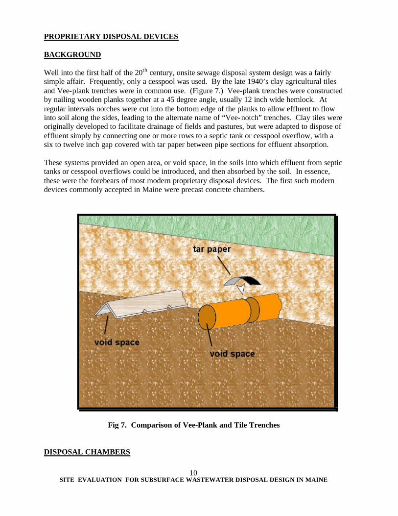
PROPRIETARY DISPOSAL DEVICES BACKGROUND Well into the first half of the 20th century, onsite sewage disposal system design was a fairly simple affair. Frequently, only a cesspool was used. By the late 1940’s clay agricultural tiles and Vee-plank trenches were in common use. (Figure 7.) Vee-plank trenches were constructed by nailing wooden planks together at a 45 degree angle, usually 12 inch wide hemlock. At regular intervals notches were cut into the bottom edge of the planks to allow effluent to flow into soil along the sides, leading to the alternate name of “Vee-notch” trenches. Clay tiles were originally developed to facilitate drainage of fields and pastures, but were adapted to dispose of effluent simply by connecting one or more rows to a septic tank or cesspool overflow, with a six to twelve inch gap covered with tar paper between pipe sections for effluent absorption. These systems provided an open area, or void space, in the soils into which effluent from septic tanks or cesspool overflows could be introduced, and then absorbed by the soil. In essence, these were the forebears of most modern proprietary disposal devices. The first such modern devices commonly accepted in Maine were precast concrete chambers.
Fig 7. Comparison of Vee-Plank and Tile Trenches DISPOSAL CHAMBERS
SITE EVALUATION FOR SUBSURFACE WASTEWATER DISPOSAL DESIGN IN MAINE
11
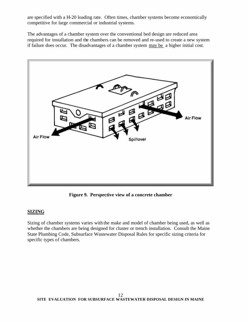
Chambers can be utilized in Maine for construction of a disposal area. A chamber is a pre-cast concrete or plastic structure which creates a void area beneath the soil. In all other aspects, a chamber system is similar to a bed system except chambers are used to form the disposal area rather than stone, hay and distribution line. (Figures 8, 9, & 10.) The Rules allows a reduction in the size of the disposal area when chambers are utilized. The rationale for the allotted reduction in disposal area is that leaching chambers provide an unmasked interface between the effluent and the soil. Calculation of the size of the chamber system is done by considering the expected volume of wastewater and the soil characteristics in which it is to be installed. Specific sizing specifications are found in the Maine State Plumbing Code, Subsurface Wastewater Disposal Rules. Chambers are manufactured and distributed with various shapes and sizes in Maine. All approved chambers may be used; the primary concern is to create the required disposal area with the type of chamber that is selected. It is important to note that there are variations in the distribution systems of various chambers, height of chambers, and availability. Consideration should be given to these factors when designing and specifying chamber systems.
Figure 8. Concrete chamber system during construction
Chamber systems are commonly used for the replacement of malfunctioning disposal areas when there is limited available space. Concrete chambers can be pre-cast with sufficient reinforcement bars so that they may be installed under parking lots or trafficable areas. These
SITE EVALUATION FOR SUBSURFACE WASTEWATER DISPOSAL DESIGN IN MAINE
12
are specified with a H-20 loading rate. Often times, chamber systems become economically competitive for large commercial or industrial systems. The advantages of a chamber system over the conventional bed design are reduced area required for installation and the chambers can be removed and re-used to create a new system if failure does occur. The disadvantages of a chamber system may be a higher initial cost.
Figure 9. Perspective view of a concrete chamber
SIZING Sizing of chamber systems varies with the make and model of chamber being used, as well as whether the chambers are being designed for cluster or trench installation. Consult the Maine State Plumbing Code, Subsurface Wastewater Disposal Rules for specific sizing criteria for specific types of chambers.
SITE EVALUATION FOR SUBSURFACE WASTEWATER DISPOSAL DESIGN IN MAINE
13
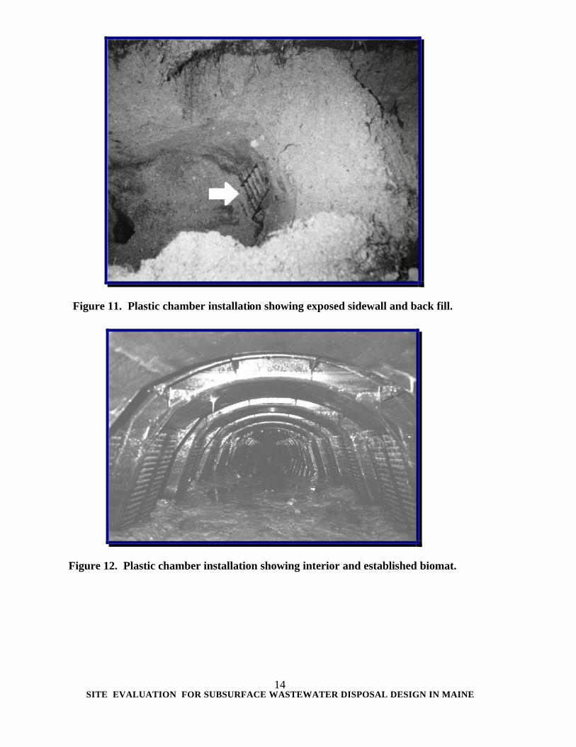
Figure 10. Manufactured concrete chamber designs and distribution methods PLASTIC CHAMBERS A major change to chambers occurred in the 1980’s when plastic chambers were introduced to the market (Figures 11, 12, & 13). The primary advantages of this device were light weight, ease of transport and installation, and increased sidewall utilization via numerous louvers in the sides of the chambers. There are now several companies which market plastic chambers in Maine, in both low and high capacity models as well as narrow models intended for trench installations. In some instances, H-20 load ratings can be achieved by following manufacturer’s directions for backfill and overburden installation. Because they have an unmasked soil interface, chambers are generally allowed a 50 percent reduction in size requirements, compared to a stone bed. Specific sizing specifications are found in the Maine State Plumbing Code, Subsurface Wastewater Disposal Rules.
SITE EVALUATION FOR SUBSURFACE WASTEWATER DISPOSAL DESIGN IN MAINE
14
Figure 11. Plastic chamber installation showing exposed sidewall and back fill.
Figure 12. Plastic chamber installation showing interior and established biomat.
SITE EVALUATION FOR SUBSURFACE WASTEWATER DISPOSAL DESIGN IN MAINE
15
Plastic chambers can be installed in cluster configuration or in trench configuration, using either serial or parallel distribution. When plastic chambers are used in a cluster configuration, only the unshielded bottom area can be used to determine its standard stone-filled disposal- field equivalent. When plastic chambers are used in a trench configuration, the sum of its unshielded bottom and sidewall area can be used to determine its standard stone-filled disposal-field equivalent. The number of plastic chambers must be rounded up to the nearest whole chamber. Although plastic chambers are generally designed to eliminate the need for stone in a disposal area, many Site Evaluators and installers prefer to place stone alongside the chambers, to prevent migration of backfill into the chambers through the louvers. Some also prefer to place the chambers on a layer of stone or gravel; however, if this is done the system must be sized as a conventional stone bed. In installations where stone is used with plastic chambers, setbacks are measured from the stone boundary, rather than the plastic chambers. Designers are strongly advised to contact the manufacturer or distributor prior to use of stone in designing a plastic chamber system. Specific sizing specifications are found in the Maine State Plumbing Code, Subsurface Wastewater Disposal Rules.
Figure 13. A narrow trench configuration plastic chamber. Specific sizing requirements are found in the Maine State Plumbing Code, Subsurface Wastewater Disposal Rules.
SITE EVALUATION FOR SUBSURFACE WASTEWATER DISPOSAL DESIGN IN MAINE
16
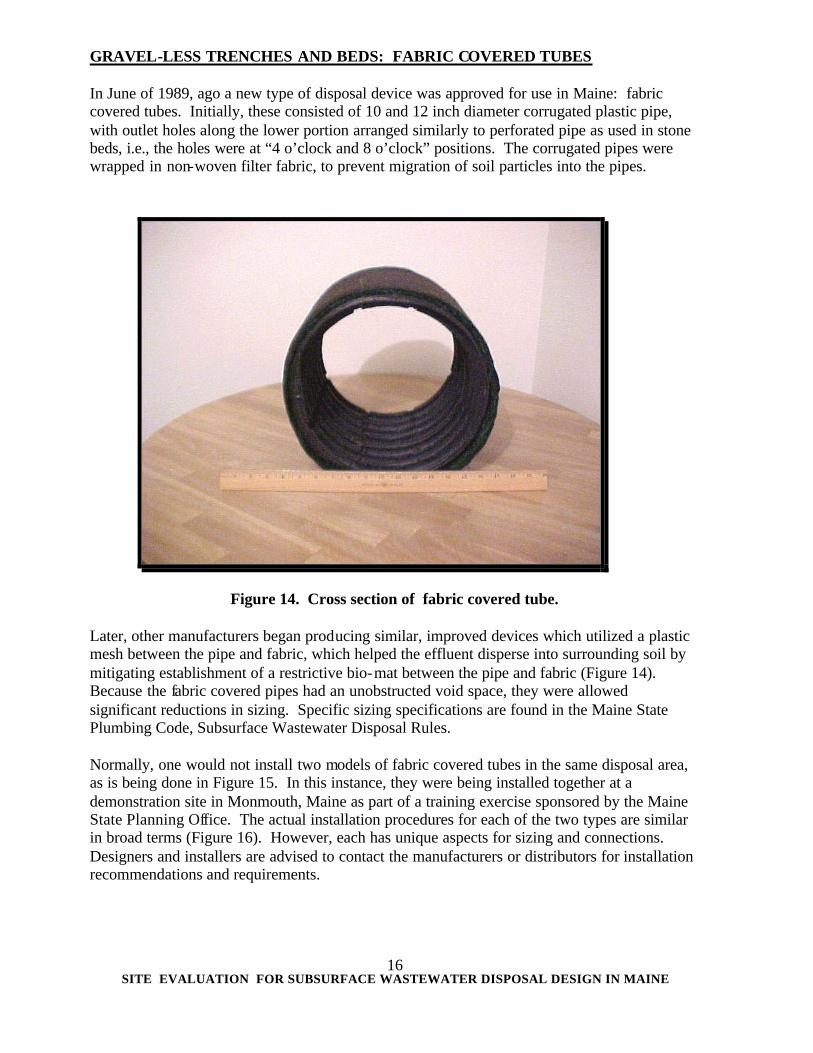
GRAVEL-LESS TRENCHES AND BEDS: FABRIC COVERED TUBES In June of 1989, ago a new type of disposal device was approved for use in Maine: fabric covered tubes. Initially, these consisted of 10 and 12 inch diameter corrugated plastic pipe, with outlet holes along the lower portion arranged similarly to perforated pipe as used in stone beds, i.e., the holes were at “4 o’clock and 8 o’clock” positions. The corrugated pipes were wrapped in non-woven filter fabric, to prevent migration of soil particles into the pipes.
Figure 14. Cross section of fabric covered tube. Later, other manufacturers began producing similar, improved devices which utilized a plastic mesh between the pipe and fabric, which helped the effluent disperse into surrounding soil by mitigating establishment of a restrictive bio-mat between the pipe and fabric (Figure 14). Because the fabric covered pipes had an unobstructed void space, they were allowed significant reductions in sizing. Specific sizing specifications are found in the Maine State Plumbing Code, Subsurface Wastewater Disposal Rules. Normally, one would not install two models of fabric covered tubes in the same disposal area, as is being done in Figure 15. In this instance, they were being installed together at a demonstration site in Monmouth, Maine as part of a training exercise sponsored by the Maine State Planning Office. The actual installation procedures for each of the two types are similar in broad terms (Figure 16). However, each has unique aspects for sizing and connections. Designers and installers are advised to contact the manufacturers or distributors for installation recommendations and requirements.
SITE EVALUATION FOR SUBSURFACE WASTEWATER DISPOSAL DESIGN IN MAINE
17
Figure 15. Fabric covered tube installation.
Figure 16. Fabric covered tubes installed for serial distribution.
SITE EVALUATION FOR SUBSURFACE WASTEWATER DISPOSAL DESIGN IN MAINE
18
GRAVEL-LESS TRENCHES AND BEDS: CUSPATED BLOCKS Another variety of proprietary disposal devices available in Maine is the cuspated block. The cuspated block system is constructed of plates of cuspated plastic, which somewhat resemble egg cartons. Non-woven filter fabric is interlaced between the cuspated plates. The fabric and cuspated plates are then bound into modules (Figures 17 & 18). The fabric provides a large surface area upon which a biomat is established, not unlike municipal trickling filters. Once established, the biomat provides a high degree of treatment of the effluent due to its high surface area to footprint ratio. This favorable ratio also allows for a significantly reduced disposal area size, compared to a conventional stone and pipe bed. Specific sizing specifications are found in the Maine State Plumbing Code, Subsurface Wastewater Disposal Rules.
Figure 17. A display sample of a cuspated block.
Designers and potential purchasers are advised to obtain information pertaining to the recommended model, relative cost, availability, installation, and maintenance procedures from the manufacturer or distributor.
SITE EVALUATION FOR SUBSURFACE WASTEWATER DISPOSAL DESIGN IN MAINE
19
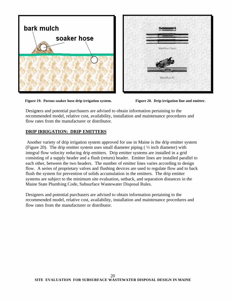
Figure 18. Installation of a cuspated block gravel-less bed. DRIP IRRIGATION The major design differences between conventional disposal systems and drip irrigation systems are a relatively uniform distribution of effluent and shallow placement of trenches. Both types of drip irrigation systems must be preceded by pretreatment which conforms to the manufacturer's specifications, to avoid or minimize clogging of the disposal lines. Subsurface drip irrigation systems are able to distribute effluent at a low application rates over the entire absorption field, which can prevent saturation of the soil and thereby facilitate aerobic treatment. Wastewater is applied in the plant root zone, which minimizes percolation of the effluent and in certain conditions accommodates evapotranspiration of the effluent. Small vibratory plows or trenchers (“ditch witches”) may be used to install drip emitter lines. DRIP IRRIGATION: SOAKER HOSES In late 1999 drip irrigation systems began to be used in significant numbers in Maine, primarily of the shallow trench porous soaker hose variety (Figure 19). The porous soaker hose system uses the soaker hose to dispose of very highly treated and disinfected effluent from an advanced treatment unit. This system is intended for installation at or above grade, either in the site’s organic soil strata (duff layer) or backfilled with bark mulch. Because of the very shallow depth at which the soaker hoses are installed, the system is approved in Maine for seasonal use only to avoid freezing problems. The soaker hose systems are subject to the minimum site evaluation, setbacks, and separation distances in the Maine State Plumbing Code, Subsurface Wastewater Disposal Rules. Specific sizing specifications are found in the Maine State Plumbing Code, Subsurface Wastewater Disposal Rules.
SITE EVALUATION FOR SUBSURFACE WASTEWATER DISPOSAL DESIGN IN MAINE
20
Figure 19. Porous soaker hose drip irrigation system. Figure 20. Drip irrigation line and emitter.
Designers and potential purchasers are advised to obtain information pertaining to the recommended model, relative cost, availability, installation and maintenance procedures and flow rates from the manufacturer or distributor. DRIP IRRIGATION: DRIP EMITTERS Another variety of drip irrigation system approved for use in Maine is the drip emitter system (Figure 20). The drip emitter system uses small diameter piping ( ½ inch diameter) with integral flow velocity reducing drip emitters. Drip emitter systems are installed in a grid consisting of a supply header and a flush (return) header. Emitter lines are installed parallel to each other, between the two headers. The number of emitter lines varies according to design flow. A series of proprietary valves and flushing devices are used to regulate flow and to back flush the system for prevention of solids accumulation in the emitters. The drip emitter systems are subject to the minimum site evaluation, setback, and separation distances in the Maine State Plumbing Code, Subsurface Wastewater Disposal Rules. Designers and potential purchasers are advised to obtain information pertaining to the recommended model, relative cost, availability, installation and maintenance procedures and flow rates from the manufacturer or distributor.
SITE EVALUATION FOR SUBSURFACE WASTEWATER DISPOSAL DESIGN IN MAINE
21
SEPTIC TANK EFFLUENT FILTERS
EFFLUENT POLISHING FILTERS
Effluent polishing filters improve the quality of septic tank effluent. Effluent polishing filters are comprised of three major types: peat modules, sand filters, and filter media devices. A potential purchaser is advised to obtain information pertaining to the recommended model, relative cost, availability, installation and maintenance procedures and flow rates from the manufacturer or distributor.
Peat Filters
Under-drained peat filters are designed to treat septic tank effluent prior to its ultimate disposal in any disposal field authorized under the Subsurface Wastewater Disposal Rules (Figure 21). Peat filters are available from several manufacturers in factory assembled modules, or they can be built on site. The disposal field is allowed a size reduction when peat filters are used. By their very nature, peat filters have a finite useful life, which will vary depending upon the level of use and the strength of the waste being treated. Eventually, the filters will need to be replaced or renovated, as appropriate depending upon the manufacturer’s recommendations.
Figure 21. Simplified cross section of a peat filter module.
Designers and potential purchasers are advised to obtain information pertaining to the recommended model, relative cost, availability, installation and maintenance procedures and flow rates from the manufacturer or distributor.
SITE EVALUATION FOR SUBSURFACE WASTEWATER DISPOSAL DESIGN IN MAINE
22
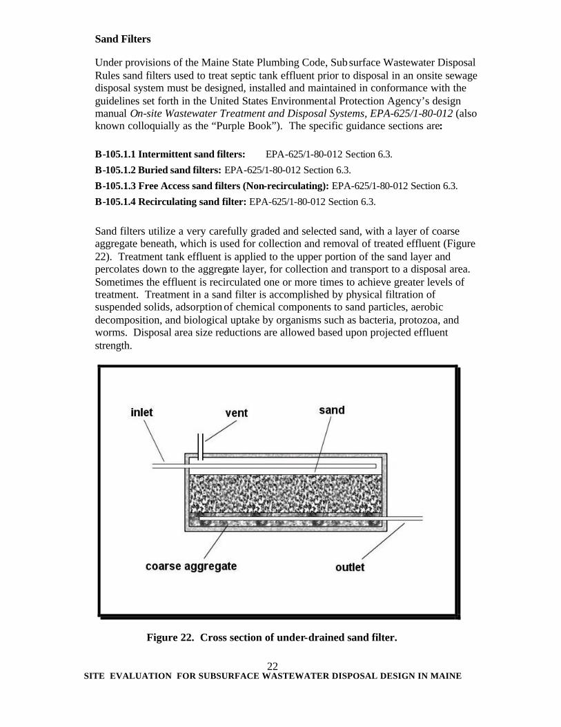
Sand Filters
Under provisions of the Maine State Plumbing Code, Subsurface Wastewater Disposal Rules sand filters used to treat septic tank effluent prior to disposal in an onsite sewage disposal system must be designed, installed and maintained in conformance with the guidelines set forth in the United States Environmental Protection Agency’s design manual On-site Wastewater Treatment and Disposal Systems, EPA-625/1-80-012 (also known colloquially as the “Purple Book”). The specific guidance sections are: B-105.1.1 Intermittent sand filters: EPA-625/1-80-012 Section 6.3.
Sand filters utilize a very carefully graded and selected sand, with a layer of coarse aggregate beneath, which is used for collection and removal of treated effluent (Figure 22). Treatment tank effluent is applied to the upper portion of the sand layer and percolates down to the aggregate layer, for collection and transport to a disposal area. Sometimes the effluent is recirculated one or more times to achieve greater levels of treatment. Treatment in a sand filter is accomplished by physical filtration of suspended solids, adsorption of chemical components to sand particles, aerobic decomposition, and biological uptake by organisms such as bacteria, protozoa, and worms. Disposal area size reductions are allowed based upon projected effluent strength.
Figure 22. Cross section of under-drained sand filter.
SITE EVALUATION FOR SUBSURFACE WASTEWATER DISPOSAL DESIGN IN MAINE
23
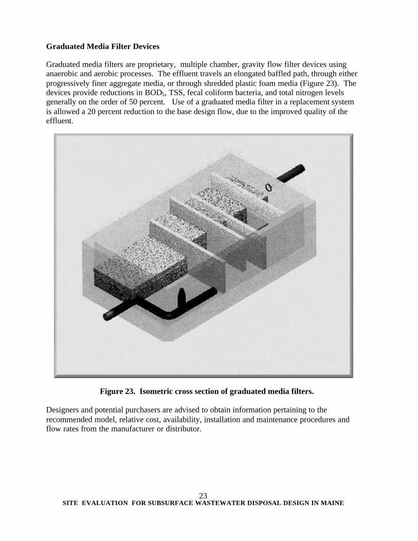
Graduated Media Filter Devices
Graduated media filters are proprietary, multiple chamber, gravity flow filter devices using anaerobic and aerobic processes. The effluent travels an elongated baffled path, through either progressively finer aggregate media, or through shredded plastic foam media (Figure 23). The devices provide reductions in BOD5, TSS, fecal coliform bacteria, and total nitrogen levels generally on the order of 50 percent. Use of a graduated media filter in a replacement system is allowed a 20 percent reduction to the base design flow, due to the improved quality of the effluent.
Figure 23. Isometric cross section of graduated media filters. Designers and potential purchasers are advised to obtain information pertaining to the recommended model, relative cost, availability, installation and maintenance procedures and flow rates from the manufacturer or distributor.
SITE EVALUATION FOR SUBSURFACE WASTEWATER DISPOSAL DESIGN IN MAINE
24
SEPTIC TANK FILTERS Septic tank filters can be categorized into two major types: outlet filters and whole tank filters. Outlet filters come from several manufacturers, and are available in a wide variety of sizes, shapes, and effective screening diameters (Figures 24 and 25).
Septic tank filters perform two primary functions; retention of the solids in the tank and lowering of the BOD5 and TSS. A potential purchaser is advised to obtain information pertaining to the recommended model, relative cost, availability, installation and maintenance procedures and flow rates from the manufacturer or distributor. Septic tank filters are particularly useful in situations where the septic tank is subjected to heavy solids loads, for example, households which use garbage grinders. The filters require regular maintenance, the frequency of which depends on the type of filter and how heavily the system is used (Figure 26).
Figure 24. Residential septic tank outlet filters.
Figure 25. Commercial/industrial septic tank outlet filters.
SITE EVALUATION FOR SUBSURFACE WASTEWATER DISPOSAL DESIGN IN MAINE
25
SITE EVALUATION FOR SUBSURFACE WASTEWATER DISPOSAL DESIGN IN MAINE
26
Figure 26. Solids being removed from an outlet filter.
WHOLE TANK FILTERS
The whole tank filter is a device inserted into an otherwise conventional septic tank, which removes suspended solids from the waste stream. (Figure 27.) Wastewater is directed by the maze into a winding path through the tank, which allows the liquid to cool and causes suspended solids to coagulate. The coagulated solids gradually build up a film on the filter’s mesh panels, which simultaneously allows microbes greater access to the nutrients for metabolizing, and encourages more solids to coagulate on the mesh. As the coagulated solids reach a critical mass, they either float to the scum layer, or sink to the sludge layer depending upon specific buoyancy . The end result is a septic tank effluent with greatly reduced BOD5 and TSS. When used in a nonresidential onsite sewage disposal system, whole tank filters allow a reduction in the system‘s disposal area size.
Figure 27. Whole tank filters
SITE EVALUATION FOR SUBSURFACE WASTEWATER DISPOSAL DESIGN IN MAINE
27
ADVANCED WASTEWATER TREATMENT UNITS AEROBIC TREATMENT UNITS Aerobic treatment units, also known as extended treatment plants, utilize an aerobic (oxygen rich) wastewater treatment process, and may be used to remove substantial amounts of BOD5 and TSS which are not removed by primary anaerobic (oxygen poor) treatment, such as occurs in septic tanks. In practical terms, aerobic treatment units can be thought of as small scale versions of municipal wastewater treatment plants. They both use the same underlying process of oxygenation of the wastewater to promote microbial treatment. Primary treatment via a conventional septic tank generally precedes the aerobic treatment unit, depending upon the make and model. The aerobic treatment units contain an aeration chamber, with either mechanical aerators or air diffusers (bubblers), and an area for final clarification (settling) (Figure 28). Some aerobic treatment units include an integral cone shaped settling well, whereas others have a separate settling chamber. Further, in some models, the settling chamber is separate from the treatment tank. Effluent from the aerobic treatment unit is conveyed either by gravity flow or pumping to either further treatment/pretreatment processes, or final treatment and disposal in a subsurface soil disposal system.
Figure 28. Simplified cross section of an aerobic treatment unit. The primary advantage of aerobic treatment units is a very high level of treatment, with significant reductions in BOD5 and TSS, and in many cases, pathogen destruction. Because the resulting effluent is low in organic loading, onsite sewage disposal system disposal areas can be reduced in size under provisions of the Maine State Plumbing Code, Subsurface Wastewater Disposal Rules. The size reduction varies according to the strength of the effluent, as measured in combined BOD5 and TSS.
SITE EVALUATION FOR SUBSURFACE WASTEWATER DISPOSAL DESIGN IN MAINE
28
The disadvantages of aerobic treatment units are electric power use and cost, increased sludge generation leading to more frequent primary (septic) tank pump-outs, and potential for owner abuse/misuse (i.e., purposely disabling the device). FIXED FILM AEROBIC TREATMENT UNITS Fixed film aerobic treatment units operate under the same general principal as standard aerobic treatment tanks, in that they utilize oxygenation of the wastewater to promote microbial treatment of the wastes. Unlike standard aerobic treatment tanks, however, fixed film tanks do not rely on the microbes to be suspended in the wastewater. Rather, a permanent growth media, generally some type of plastic or foam material immersed in or suspended above the wastewater, is provided upon which the microbes attach and form a layer of biological growth (Figure 29). The greater the surface area exposed to the wastewater, the greater the level of treatment as more of the biological growth is exposed to the nutrients in the waste. As the biological growth thickens, it sloughs off and settles with the suspended solids in the settling chamber, and is recirculated back to the primary treatment tank.
Figure 29. Simplified cross section of a fixed film aerobic treatment unit. The primary advantage of fixed film aerobic treatment units is a very high level of treatment, with significant reductions in BOD5 and TSS, often much higher than a standard aerobic treatment tank. As with aerobic treatment tanks, because the resulting effluent is low in organic loading, onsite sewage disposal system disposal areas can be reduced in size under provisions of the Maine State Plumbing Code, Subsurface Wastewater Disposal Rules. The size reduction varies according to the strength of the effluent, as measured in combined BOD5 and TSS.
SITE EVALUATION FOR SUBSURFACE WASTEWATER DISPOSAL DESIGN IN MAINE
29
The disadvantages of fixed film treatment aerobic treatment units are also electric power use and cost, increased sludge generation leading to more frequent primary (septic) tank pump-outs, and potential for owner abuse/misuse (i.e., purposely disabling the device). RECIRCULATING AEROBIC TREATMENT UNITS Recirculating aerobic treatment units take the concept of the fixed film treatment aerobic treatment units one step further, by spraying the wastewater onto porous filter media. (Figure 30.) Microbes in the media have access to large quantities of both food and oxygen, and provide an extremely high level of treatment. The treated wastewater then trickles back into the main compartment of the tank, where it provides oxygen to waste stream. The wastewater may be sprayed on the filter media several times before the final effluent is conducted to a disposal area. As with aerobic units and aerobic fixed film units, the disposal area size may be reduced based upon the final effluent strength. The size reduction varies according to the strength of the effluent, as measured in combined BOD5 and TSS.
Figure 30. Simplified cross section of a recirculating aerobic treatment tank. In common with other aerobic units, the primary advantage of recirculating aerobic treatment units is a very high level of treatment. The major difference, however, is that recirculating aerobic treatment units routinely produce effluent with BOD5 and TSS measured in single digits.
SITE EVALUATION FOR SUBSURFACE WASTEWATER DISPOSAL DESIGN IN MAINE
30
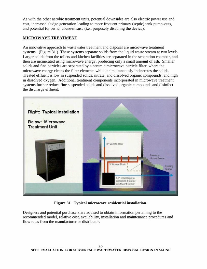
As with the other aerobic treatment units, potential downsides are also electric power use and cost, increased sludge generation leading to more frequent primary (septic) tank pump-outs, and potential for owner abuse/misuse (i.e., purposely disabling the device). MICROWAVE TREATMENT An innovative approach to wastewater treatment and disposal are microwave treatment systems. (Figure 31.) These systems separate solids from the liquid waste stream at two levels. Larger solids from the toilets and kitchen facilities are separated in the separation chamber, and then are incinerated using microwave energy, producing only a small amount of ash. Smaller solids and fine particles are separated by a ceramic microwave particle filter, where the microwave energy cleans the filter elements while it simultaneously incinerates the solids. Treated effluent is low in suspended solids, nitrate, and dissolved organic compounds; and high in dissolved oxygen. Additional treatment components incorporated in microwave treatment systems further reduce fine suspended solids and dissolved organic compounds and disinfect the discharge effluent.
Figure 31. Typical microwave residential installation. Designers and potential purchasers are advised to obtain information pertaining to the recommended model, relative cost, availability, installation and maintenance procedures and flow rates from the manufacturer or distributor.
SITE EVALUATION FOR SUBSURFACE WASTEWATER DISPOSAL DESIGN IN MAINE
31
PUMPING Pumping is necessary when the treatment tank outlet is lower in elevation than the proposed distribution line. Pumping is usually required when: 1. There is a suitable area at a higher elevation on a parcel of land for installation of a
disposal system and the elevation of the building sewer does not allow for gravity feed,
2. Replacing an existing disposal field that can not flow by gravity from an existing
septic tank because the original system had been placed in or very near to the seasonal high ground water table, or
3. A pressurized or periodically dosed distribution system would be more
advantageous due to special soil considerations or size of disposal system. An effluent pump is placed on the outlet side of the treatment tank or a separate chamber near the tank outlet, and designed to pump wastewater from the treatment tank to the disposal area, after the solids have settled out. A sewage grinder pump or sewage ejector can be placed on the building sewer drain and is designed to pump raw sewage, which contains solids from the building up into a treatment tank. It is usually preferable to install an effluent pump when feasible rather than a sewage grinder pump or sewage ejector. Sewage grinder pumps and sewage ejectors are more costly than an effluent pump and they also require that the septic tank capacity be increased or a dual compartment tank be installed to provide for adequate primary treatment. (Figures 32 & 33.) The advantages of pumps are that they can raise the elevation of wastewater and allow it to enter a disposal field when gravity flow is not possible and provide for periodic dosage or pressure distribution. The disadvantages of pumps are that they are more expensive than a gravity flow system, require an energy source, and require periodic maintenance. Pumping stations should be sited in locations and elevations which are not subject to either surface or ground water infiltration. Care should be taken to prevent groundwater infiltration (leading to constant pumping), and to ensure that access risers and alarms are properly installed. Improper sizing of pumping chambers may lead to premature pump or disposal area failure due to excess water being added to the system. DOSING Dosing of a disposal area can be accomplished by a pump or siphon. A dosing siphon can only be used, however, when the disposal area is below the elevation of the outlet of the dosing tank. A dosing siphon is non-mechanical and has no power requirements; however, it has no lifting ability and is relatively difficult to install properly.
SITE EVALUATION FOR SUBSURFACE WASTEWATER DISPOSAL DESIGN IN MAINE
32
Figure 32. Effluent and sewage lift station design layouts
Figure 33. Pump tank and effluent pump for single family residence
SITE EVALUATION FOR SUBSURFACE WASTEWATER DISPOSAL DESIGN IN MAINE
33
II SITE EVALUATION The physical characteristics of a parcel of land must be fully evaluated in order to design a safe and effective disposal system. Each site has its own unique characteristics and limitations which must be observed and considered in the design. Observations of the surrounding land and development are just as important as viewing the particular parcel of land under consideration. The Site Evaluator, who is contracted to do an on-site investigation, usually meets with the applicant (e.g. property owner, prospective buyer, real estate agent, developer) on the lot or has previously obtained the necessary information to properly conduct the evaluation. It is very beneficial to have the interested party on-site during the investigation to discuss possible alternatives and to answer any questions. It is also beneficial to have the Local Plumbing Inspector (LPI) there during the on-site if it can be arranged. The LPI’s presence may be very helpful to resolve any difficult situations that may be encountered plus give the Site Evaluator an opportunity to explain the existing conditions to the LPI. Some towns have adopted an ordinance requiring that the LPI be notified of the scheduled on-site investigation. This ordinance has worked out very well by getting the Site Evaluator and Local Plumbing Inspector working together in the field. The Site Evaluator must observe and record all physical characteristics of the site which are pertinent to the design of a system while concentrating on the unique characteristics of the site, which may require special consideration. (Figure 34.) LOCATION OF THE PARCEL OF LAND Names of neighboring property owners, relevant land marks, and distance from intersections, etc., should be noted. ARRANGEMENTS AND AGREEMENTS Scheduled date of on-site, arrangements for a backhoe or other means of excavation of test pits, scheduled date for completion of forms, mailing addresses and fees should be clearly stated at the very beginning. (Both the Site Evaluator and applicant should reach an understanding as to what the Site Evaluator’s fee covers, who pays for the backhoe if necessary, and other details). SIZE OF LOT Dimensions & bearings of property lines, location of irons, monuments, etc., should be noted. A copy of the plot plan or a tracing off the municipal tax map is desirable. TYPE OF PROPOSED DEVELOPMENT AND SIZE What is the proposed development and of what size? For example, single family dwelling (2 bedrooms), restaurant (30 seat capacity), apartment complex (30 units; 2 bedrooms, 15 units; 1 bedroom) etc.
SITE EVALUATION FOR SUBSURFACE WASTEWATER DISPOSAL DESIGN IN MAINE
34
PRELIMINARY CONCEPTS Sometimes the applicant has a preference to where the building is to be placed if the soil conditions are accommodating. First considerations should be given to the desired locations if at all possible. However, if limited soils are available, the Site Evaluator may have to discuss alternative plans with the applicant so that the disposal system can be sited in accordance with the Rules and the building can be sited at an acceptable location. ZONING AND LOCAL ORDINANCES A Site Evaluator must be aware of the zoning of the area. Also, it is the responsibility of the Site Evaluator to be familiar with any local ordinances which may be pertinent. Some communities have adopted local ordinances that are more stringent than the State’s Rules with regards to setback distances and minimum soil conditions, and have passed ordinances requiring that the Local Plumbing Inspector be notified of any scheduled on-site so that he or she may attend if scheduling permits. EASEMENTS OR SPECIAL CONSIDERATIONS There are instances when a Site Evaluator must pursue the possibility of obtaining an easement on abutting land with suitable soils for installation of a disposal system. An easement must be filed in the Registrar of Deeds so that a disposal system can be installed and maintained on the consenting abuttor’s property. MINIMUM LOT SIZE LAW No person shall dispose of waste from any single family residential unit by means of subsurface wastewater disposal unless such lot of land contains at least 20,000 square feet (possibly more if in LURC Territory or by local ordinance). For multiple unit housing or other land use activities, the lot size shall have 66.66 square feet of land area for each gallon per day of wastewater generated. Example: A commercial development proposed to generate 750 G.P.D. would require a minimum lot size of 50,000 square feet (750 x 66.66). Specific questions on interpretations regarding this law should be directed to the Division of Health Engineering. LOCATION OF WATER BODIES The Site Evaluator should keep in mind the set-back distances from water bodies (streams, brooks, lakes, ponds, marshes, bogs, and intermittent streams). SLOPE OF TERRAIN Systems are permitted on slopes up to 20 percent. Systems must be sufficiently set back from steep downhill slopes to allow for proper fill gradients to the original soil. The steeper the slope, the longer the fill extension required.
SITE EVALUATION FOR SUBSURFACE WASTEWATER DISPOSAL DESIGN IN MAINE
35
SURFACE DRAINAGE Surface drainage characteristics are considered in the design of a system. Surface drainage ditches in a pasture or cultivated field may suggest that the seasonal high ground water table may be near the surface during the wet periods of the year. Evidence of water ponding in depressional areas may be used with discretion as an indicator of soil drainage conditions. Consideration of runoff rate and direction is necessary for planning diversion ditch locations to increase the potential of an area for wastewater disposal. WATER SUPPLY, TYPE AND WELL LOCATIONS IN VICINITY Disposal systems are required to be 100 feet from wells and other sources of drinking water supplying less than 2,000 gallons per day (gpd), 200 feet from those supplying between 2,000 and 2,999 gpd, and 300 feet from those exceeding 2000 gallons per day. Disposal systems are required to be set back at least 300 feet from any public water supply source, regardless of supply volume. The Site Evaluator must also insure that the proposed location of the disposal system will not prohibit the property owner from having a reliable water supply on the property. (See Fig. 25) NATIVE VEGETATION The native vegetation may give a broad indication of the inherent soil drainage conditions. The presence of alders, ferns, willows, cat tails, and other wetland vegetation suggest poor drainage conditions. Hardwoods and trees that have a deep tap root may indicate moderate to well drained soil. The prevalence of tree throws, blow downs, and scrubby growth may be caused by the presence of a restrictive layer in the soil substratum or poor drainage. An unexpected lack of vegetation may indicate droughty conditions or shallowness to bedrock. TERRAIN AND POSITION IN LANDSCAPE The landscape position on the site should be evaluated (knoll, upland, sideslope, or depressional area). This factor is important when considering the extent of the drainage shed and site modifications (See Figure 35). FLOOD PLAINS A Site Evaluator must be able to recognize flood plain zones (areas prone to seasonal flooding). No system shall be installed in the ten year flood plain except for a replacement system (See Chapter V, Flood Plains for more information). (Figure 36.) BEDROCK OUTCROPPING Outcropping of bedrock is prevalent when there is shallow soil coverage. The Rules require a minimum of 12 to 15 inches of suitable soil above bedrock to pass a site evaluation. The Rules require a minimum of 24 inches of suitable mineral soil beneath the entire proposed disposal area when constructed.
SITE EVALUATION FOR SUBSURFACE WASTEWATER DISPOSAL DESIGN IN MAINE
36
Landscape and bedrock surface contours can affect drainage conditions of shallow soils. A depression in the bedrock surface beneath the ground surface can collect ground water to create poor drainage conditions in that localized area. ELEVATION REFERENCE POINT An elevation reference point is required to indicate and determine the finished elevation of a system. A permanent marker should be used for establishing a reference elevation. When there are existing dwellings or structures, the top of the building foundation or a concrete slab is a very good choice. On undeveloped lots, a corner stone or iron pin can be utilized. Often times it is necessary to set an elevation reference with a nail in a tree. A Site Evaluator must choose a location for the elevation reference point that will not be destroyed or disturbed during construction of the proposed area. Standard practice is to establish the elevation reference point as 0 inches elevation, and to reference construction elevations as positive values when higher than the elevation reference point, and negative values when lower. LAND USE Consideration should be given to future or existing land use activities on the property when siting a disposal system. Garden plots, firewood storage, vehicular traffic, potential building expansions, and other activities may affect layout of the system to some extent. PROFESSIONAL STATEMENT ON ADEQUACY OF DISPOSAL SYSTEMS Site Evaluators, due to their expertise in subsurface wastewater disposal, are occasionally requested to evaluate the condition or potential of an existing disposal system. The request may be from loan institutions, prospective buyers, or owners who desire to expand their businesses or dwellings. If the system was legally installed after 1974, there is a high probability that a copy of the application for the permit could be found either at the Municipal Town Hall or with the Division of Health Engineering. This application would have a record of the original soil conditions reported, size of disposal system components and design flow data. The theoretical potential for the system could then be calculated based on the current design specifications. An objective statement on the ability of the system could then be made based on field assessment and theoretical design capacity. Records of systems installed prior to 1974 are generally incomplete. The Division of Health Engineering does not have this information; neither do most municipalities. For the most part, systems constructed prior to 1974 would not meet today’s standards. The value of excavating into an old system for observation is questionable and is not recommended due to the risk of damage. Health Engineering is of the opinion that an evaluation of what it would take to replace the existing system with its proposed increased wastewater flow is of more value, and more objective, than to attempt to determine the flow capacity of an old existing disposal area constructed prior to 1974.
SITE EVALUATION FOR SUBSURFACE WASTEWATER DISPOSAL DESIGN IN MAINE
37
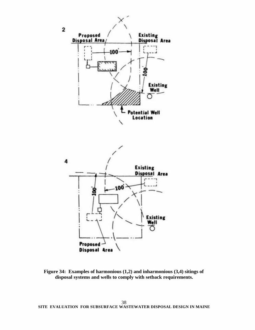
Figure 34: Examples of harmonious (1,2) and inharmonious (3,4) sitings of
disposal systems and wells to comply with setback requirements.
SITE EVALUATION FOR SUBSURFACE WASTEWATER DISPOSAL DESIGN IN MAINE
38
Figure 34: Examples of harmonious (1,2) and inharmonious (3,4) sitings of
disposal systems and wells to comply with setback requirements.
SITE EVALUATION FOR SUBSURFACE WASTEWATER DISPOSAL DESIGN IN MAINE
39
Figure 35. Position in landscape
Figure 36. Flood Plain
SITE EVALUATION FOR SUBSURFACE WASTEWATER DISPOSAL DESIGN IN MAINE
40
LOCATION OF OBSERVATION HOLES A Site Evaluator may evaluate several test pits in the vicinity of the disposal field to assure that the soil conditions observed are continuous throughout the entire proposed disposal area. Professional discretion is used in determining the location and number of observation pits. Experience is useful for developing expectations of soil characteristics with relation to landscape, geology, slope, and vegetation. (See Chapter III). Measurements to observation holes must be made on-site so that their accurate location can be shown on the site plan. (Figure 36.) LOG OF SOIL PROFILE The characteristics observed of the soil profile are recorded. (This is discussed in Chapter III, Soil Evaluation). PUBLIC RELATIONS Site Evaluators should explain to each client what is being done and why. Discussion about observations in relation to the requirements of the Rules is important for the applicant to get an understanding of the site evaluation concept and helps the Site Evaluator to maintain good public relations. DESIGN AND FIELD LAYOUT The Site Evaluator reviews the project proposed after completing the investigation of the site and soil conditions. The Site Evaluator will select a system in accordance with the Rules and will locate a suitable area for the disposal system that is most conducive to its installation and proper functioning. Stakes or temporary markers are placed in the proposed corners of the disposal area to aid the contractor or developer in locating the proposed site. The Evaluator must observe and then record and report on the Subsurface Wastewater Disposal Application (HHE-200 Form) all the pertinent features of the site which influence the design of the system. Consequently, important features (existing buildings, water bodies, test pits, property lines, etc.) are measured and located from permanent markers (corner iron, telephone pole, monument, etc.). A Site Evaluation is not complete until all necessary information is gathered to report the soil characteristics (Discussed in Chapter III) and to draft the site characteristics on the Application (Discussed in Chapter IV).
SITE EVALUATION FOR SUBSURFACE WASTEWATER DISPOSAL DESIGN IN MAINE
41
Figure 37. Test pit excavated with a backhoe to a depth of four feet
SITE EVALUATION FOR SUBSURFACE WASTEWATER DISPOSAL DESIGN IN MAINE
42
III SOIL EVALUATION Soil is the upper weathered and biologically molded part of the earth’s crust that supports plant growth. Soil consists of solids, water and air. The “average” mineral soil is comprised of 50 percent by volume solids, of which approximately 45 percent is mineral and 5 percent organic. The remaining 50 percent is comprised of highly variable percentages of air and water which are subjected to great fluctuations. (Figure 38.) The mineral soil fraction is comprised of rock fragments and minerals which are dependent upon the type of material from which it was derived and the weathering environment. The organic portion is comprised of partially decayed and synthesized plant and animal residues. The soil solution contains small but significant amounts of dissolved solids; and is usually slightly acidic in Maine due to biological activity and the type of vegetation.
Figure 38. Components of soil
SITE EVALUATION FOR SUBSURFACE WASTEWATER DISPOSAL DESIGN IN MAINE
43
Figure 39. Theoretical soil horizonation Soil covers most of the land surface of Maine but it is highly variable both horizontally and vertically. The soil characteristics are influenced by the type of material from which it was derived (parent material), the climate, vegetation, topography and age. Local variations in soil conditions are usually due to variation in parent material and natural drainage conditions which is related to its position in the landscape. Each soil has unique characteristics that make it possible to identify and classify it. (Figure 39.) Individual soils are three dimensional. They may be a few inches or several feet thick and are usually comprised of several layers (or horizons). Each horizon is identified by a combination of properties including color, texture, structure and consistence. Soil conditions can be relatively similar for extensive areas and can also be very variable within several feet. Because of the possibility for variation within a very small area, the Site Evaluator must excavate a sufficient number of observation pits to assure that the conditions observed are indicative of the total area under the proposed system.
SITE EVALUATION FOR SUBSURFACE WASTEWATER DISPOSAL DESIGN IN MAINE
44
SOIL PROFILES Soils are described by digging an observation pit four feet deep or until refusal and observing the exposed soil profile which consists of soil horizons. Soil horizons are differentiated by variation in soil characteristics (i.e. texture, structure, color, etc.). Site Evaluators should be primarily concerned with soil characteristics that influence the suitability of soils for wastewater disposal; although it is valuable for Site Evaluators to be familiar with the terminology used for soil descriptions in more sophisticated classification system such as the Natural Resources Conservation Service, U.S.D.A. Soil Taxonomy. Horizons in the Soil Taxonomy system are classified using the combination of capital letters, O, A, E, B, C, and R along with lower case letters a, e, g, h, I, m, p, r, s, w, and x as suffixes. (Figure 40.) MASTER HORIZONS O HORIZON. A layer of organic matter. Soils found in a forest or bog environment commonly have a surface layer consisting of leaves, twigs, humus or other organic material. A HORIZON. A surface soil mineral horizon characterized by a highly humified organic matter content intimately mixed with the mineral fraction. The A Horizon may have properties resulting from cultivation, pasturing or similar kinds of disturbance. E HORIZON. A layer of maximum leaching (eluviation) of iron, aluminum, and organic matter. The E Horizon is usually lighter in color than the overlying or underlying horizons. An E Horizon is commonly near the surface below an O or A Horizon and above a B Horizon. B HORIZON. The B Horizon is usually below the E Horizon and in this region is generally a horizon of maximum accumulation (illuviation) of iron, aluminum, or organic matter. A dark reddish brown to a yellowish brown color maybe evident in the more developed horizons. C HORIZON. The C Horizon consists of material that has been only slightly altered by the process of soil formation, but it may have been slightly modified by weathering. R. This symbolizes solid bedrock. SUBORDINATE DISTINCTIONS WITHIN MASTER HORIZONS a- Highly decomposed organic material. This symbol is used with “O”. c- Concretions or hard nodules. Iron, aluminum concretions. e- Organic material of intermediate decomposition. This symbol is used with “O”. g.- Strong gleying. Indicates that iron has been reduced or that saturation with stagnant water has preserved a reduced environment. Gray and bluish gray colors prevail. h- Illuvial accumulations of organic matter. This symbol is used with “B” to indicate the accumulation of dispersible organic matter – and to a lesser extent sesquioxide complexes (iron and aluminum compounds).
SITE EVALUATION FOR SUBSURFACE WASTEWATER DISPOSAL DESIGN IN MAINE
45
i- Slight decomposed organic matter. This symbol is used with “O”. m- Cementation. Indicates continuous cementation where roots will not penetrate, but through cracks. If iron is the predominant cementing agent, “qm” is used. p- Plowing or other similar disturbance. This symbol used most commonly with “A”, but can be used with “O”. A disturbed mineral horizon, even though once an “E, B, or C” horizon is designated “Ap” r- Weathered bedrock. This symbol is used with “C” to indicate weathered bedrock that can be dug with a spade. s- Illuvial accumulation of iron, aluminum and organic matter. This symbol is used with “B” and may also be combined with “h” as “Bhs”. w- Development of color or structure. This symbol is used with “B” to indicate development of color or structure with little illuvial accumulation of material. x- Fragipan character. Used to indicate a fragipan or fragipan like layer that may not be genetically developed, but is firm, brittle or of high bulk density. SOIL FORMATION Soil formation in Maine has occurred since the last glacier retreated about 13,500 years ago. The major soil forming process resulting from the weathering process (interaction of climate, time, topography, vegetation and parent material) is podzolization. In podzolization, material is removed by leaching from the E Horizon and deposited in the lower B Horizon. The materials that is leached in Maine soils is iron, aluminum and organic matter. The E Horizon, from which these materials were removed, consequently becomes grayish to whitish in color. The B Horizon, where these materials are deposited, subsequently becomes dark reddish brown to yellowish brown. Soils in which the podzolization process is not intense enough lack strong color horizonation.
SITE EVALUATION FOR SUBSURFACE WASTEWATER DISPOSAL DESIGN IN MAINE
46
Figure 40. Typical soil SOIL TEXTURE Soil texture refers to the relative proportions of the various size groups of individual soil grains in a mass of soil. Specifically it refers to the proportions of clay, silt and sand which are the fine earth material less than 2 millimeters in diameter. These individual sized groups of mineral particles (i.e. clay, silt and sand) are commonly referred to as soil separates (See Table 4). Soil texture of a soil horizon is a nearly permanent characteristic and greatly influences infiltration, permeability, aeration, drainage, cation exchange capacity, fertility and many other characteristics. Soil texture is one of the primary characteris tics considered when designing disposal systems due to the large influence of texture on the characteristics of a soil. Rarely does soil consist completely of one separate. Classes of soil texture are based on different combinations of sand, silt and clay. The basic classes usually encountered in Maine in order of increasingly finer texture are: sand, loamy sand, sandy loam, loam, silt loam, silt, silty clay loam and silty clay (See Figure 41). The determination of soil textural class is made in the field during an on-site investigation by feeling and observing the soil. This requires skill and experience of the Site Evaluator. Table 5 describes the various feelings and appearance of various soil textural classes. The Maine Subsurface Wastewater Disposal Rules utilize the United States Department of Agriculture c1assification scheme for size limits of soil separates. Table 4 lists the soil separates and diameter ranges.
SITE EVALUATION FOR SUBSURFACE WASTEWATER DISPOSAL DESIGN IN MAINE
47
Significant proportions of fragments coarser than sand are recognized by an appropriate adjective.
Table 4. Soil Separates
Figure 41. Soil textural triangle
NAME OF SEPARATE
DIAMETER (range) mm.
Very coarse sand
2.00 – 1.00
Coarse sand
1.00 – 0.50
Medium sand
0.50 – 0.25
Fine sand
0.25 – 0.10
Very fine sand
0.10 – 0.05
Silt
0.5 – 0.002
Clay
0.002
SITE EVALUATION FOR SUBSURFACE WASTEWATER DISPOSAL DESIGN IN MAINE
48
Table 5. Feelings and appearance of various soil textural classes.
Soil Textural Class
Dry Soil
Moist Soil
Sand Loose, single grains which feel gritty. Squeezed in the hand the soil mass falls apart when the pressure is released.
Squeezed in the hand it forms a cast which crumbles when lightly touched. Does not form a ribbon between thumb and forefinger.
Loamy Sand Loose, single grains which feel gritty but enough fine particles to stain fingerprints in palm of hand.
Squeezed in the hand it forms a cast which crumbles when touched and only bears very careful handling.
Sandy Loam Aggregates are easily crushed. Very faint, velvety feeling initially, but as rubbing is continued, the gritty feeling of sand soon dominates.
Forms a cast which bears careful handling without breaking. Doesn’t form a ribbon between thumb and forefinger.
Loan Aggregates are crushed under moderate pressure; clods can be quite firm. When pulverized, loam has a velvety feel that becomes gritty with continued rubbing.
Cast can be handled quite freely without breaking. Very slight tendency to ribbon between thumb and forefinger. Rubbed surface is rough.
Silt Loam Aggregates are firm but may be crushed under moderate pressure. Clods are firm to hard. Smooth, flour-like feel dominates when soil is pulverized.
Cast can be freely handled without breaking. Slight tendency to ribbon between thumb and forefinger. Rubbed surface has a broken or rippled appearance.
Silty Clay Loam Aggregates are very firm. Clods are hard to very hard.
Cast can be handled very firmly without breaking. Tendency to ribbon between thumb and forefinger with some flaking, greasy feeling, moderately sticky.
Silty Clay Squeezed with proper moisture content into a long ribbon, sticky feel.
SITE EVALUATION FOR SUBSURFACE WASTEWATER DISPOSAL DESIGN IN MAINE
49
Table 6. Coarse Fragments
Particle size diameter Gravel
Up to 3”
Cobbles
3” to 10”
Stones
More than 10”
When soil contains 15 to 35% by volume of coarse fragments, coarse fragment adjective is incorporated with the textural name (i.e. gravelly sandy loam, cobbly sandy loam, etc.). When the coarse fragments make up 35 to 60% the word “very” is used as a modifier along with the coarse fragment and textural adjective terms (very gravelly sandy loam, very cobbly loamy sand, etc.) When soil contains 60 to 95% by volume of coarse fragments, the work “extremely” is used as a modifier of the textural term. When the volume of coarse fragments is about 95% or more, and there is too little fine earth to determine the textural class, the terms gravel, cobbles, stones are used in place of fine earth texture.
Figure 42. Silty clay soil ribboning
SOIL PARENT MATERIAL Parent material is the physical body of soil and its associated chemical and mineralogical properties at the starting point of soil formation. There are 6 major types of parent material found in Maine (See Table 7).
SITE EVALUATION FOR SUBSURFACE WASTEWATER DISPOSAL DESIGN IN MAINE
3) marine Ocean deposit 4) Lacustrine Lake sediment 5) Alluvial deposit River, stream
Organic
6) Organic Peat bog, marsh, swamp
GLACIAL TILL Material deposited directly by the glacial ice mass is called glacial till. It is the oldest and one of the most widespread surficial material in Maine. Till generally overlies bedrock. Glacial till deposits in Maine are comprised of sediments of textural classes ranging from silt loam, loam, sandy loam and loamy sand. Angular coarse fragments of gravel, cobbles or stones are common (Figures 43 & 44). Generally there is no evidence of stratification due to sorting by water flow. Till may contain thin, discontinuous beds of washed sediments, but pronounced bedding is rare. Large stones may be present at the surface or within the profile.
SITE EVALUATION FOR SUBSURFACE WASTEWATER DISPOSAL DESIGN IN MAINE
51
Figure 43. Valley glacier illustrating sediment deposition
Figure 44. Profile of soil derived from glacial till
SITE EVALUATION FOR SUBSURFACE WASTEWATER DISPOSAL DESIGN IN MAINE
52
There are two basic sub-categories of glacial till in Maine; basal till and ablation till. Basil till was laid down at the bottom of a glacier. It is fine grained, compact, and difficult to excavate. This kind of till is often called “hardpan”. Ablation till was deposited by the settling of particles from melting glacial ice. It is loose, sandy and easy to excavate. Ablation till may grade locally into stratified drift material.
Figure 45. Valley glacier illustrating sediment deposition STRATIFIED DRIFT DEPOSITS Stratified drift deposits were laid down by glacial meltwater streams from the last glacier. (Figure 45.) These deposits can be classified into ice contact stratified drift and proglacial outwash. Ice contact stratified drift include kames, kame terraces, eskers and deltas. Proglacier outwash includes outwash plains. NAME DEPOSITIONAL ENVIRONMENT: Kame Randomly deposited on, within, beneath, or adjacent to melting glacial ice. Kame terrace Usually deposited between stagnant ice and a nearby valley – wall; upper
surface was graded by streams and is flatter than a kame. Esker Deposited in a tunnel within or beneath stagnant ice. Delta Built into a lake or the ocean; may have formed in contact with glacier ice
or at the end of an esker, whence the varieties “kame delta” and esker delta”.
Outwash plain Formed beyond the margin of the glacier and may terminate in a delta if the
meltwater stream entered standing water.
SITE EVALUATION FOR SUBSURFACE WASTEWATER DISPOSAL DESIGN IN MAINE
53
Each type of stratified drift deposit has unique characteristics and composition. However, all of stratified drift deposits will exhibit some degree of stratification. Stratification is alternating layers different but well sorted particles. They range in textural classification from fine sand to gravel (Figure 46).
Figure 46. Stratified glacial drift deposit MARINE SEDIMENT Material deposited on an ocean floor is referred to as marine sediment (Figure 47). Fine sediment washed out of the glacier that covered Maine during the “Ice Age” (Pleistocene), and accumulated on the ocean floor. The ocean, during that period extended inland along the major river valleys. Marine deposits can be found over 300 feet above present sea level in parts of Maine (Figure 48). Terrain underlain by marine sediments are usually gently sloping. The soil consists primarily of silt loam, silty clay loam and silty clay. Marine sediments are often called “clay” but the correct textural class is usually silt loam, silty clay loam or silty clay. These types of deposit usually become firm and dense with increasing soil depth (See Figure 49).
SITE EVALUATION FOR SUBSURFACE WASTEWATER DISPOSAL DESIGN IN MAINE
54
LACUSTRINE DEPOSITS The soil textures of lacustrine sediments are usually slightly coarser than marine sediments and they may exhibit lenses of fine sand and sandy loam material in the substratum. ALLUVIAL DEPOSITS Water-deposited sediment found on flood plains and terraces along modern rivers is called alluvial. These are very young soils with very little soil horizonation (Figure 50).
Figure 47. Recent sediment deposited in marine environment
Figure 48. Profile of soil derived from marine sediment
SITE EVALUATION FOR SUBSURFACE WASTEWATER DISPOSAL DESIGN IN MAINE
55
Figure 49. Extent of glacio-marine clay in Maine
Figure 50. Cross section showing relationships among surficial deposits, generalized
SITE EVALUATION FOR SUBSURFACE WASTEWATER DISPOSAL DESIGN IN MAINE
56
ORGANIC DEPOSITS Material composed of primarily organic matter in swamps, bogs, and marshes. To qualify as organic soils, the surface organic layer must be at least 16 inches thick and may be underlain by mineral soils. Occasionally, organic soils can be developed due to cold climates and not as a result of saturation. SOIL WETNESS Knowledge of the times and depths at which a soil is wet is very important in using the soil for subsurface wastewater disposal. Free water is very influential on the biological, chemical and physical processes. Soil characteristics, climate, slope and landscape position influence soil wetness. Precipitation, runoff, infiltration, and permeability also affect the degree and duration of wetness. A soil at a higher elevation may have a deeper water table or have a shorter duration of wetness than the same soil at a lower elevation downslope. Although the depth to ground water table changes greatly during and between years, most soils usually have typical times and depths of saturation. Soil morphology is used to infer moisture conditions in a soil. Soil color, texture, structure and consistence will enable the skilled and experienced observer to characterize soil wetness. SOIL DRAINAGE CLASSES Soil drainage refers to the condition of soil saturation that exists in a soil and the frequency and duration of the periods of saturation. There are seven drainage classes recognized by the U.S.D.A. Classification System, which are listed below in increasing order of saturation, duration, and frequency. Excessively drained
Water is removed from the soil very rapidly. Excessively drained soils are very coarse textured, stony, or very shallow (Less than 10 inches). Some are steep. All are free of soil morphological features associated with saturation.
Somewhat excessively drained
Water is removed from the soil rapidly and the soils do not have a seasonal water table within 40 inches of the mineral soil surface. Somewhat excessively drained soils are similar to excessively drained soils in texture except that they have a thicker cap, if greater than 40 inches to bedrock, if shallow (between 10 inches and 20 inches deep) they are deeper than excessively drained soils.
SITE EVALUATION FOR SUBSURFACE WASTEWATER DISPOSAL DESIGN IN MAINE
57
Well drained
Water is removed from the soils readily but not rapidly. Water is available to plants throughout most of the growing season. Wetness does not inhibit growth of roots for significant periods during most growth seasons. Well drained soils are commonly medium textured. They are mainly free of soil morphological features associated with saturation, within the upper 40 inches.
Moderately well drained
Water is removed from the soil somewhat slowly during some periods. Moderately well drained soils are wet for only a short time during the growing season. They commonly have a slowly permeable layer within the substratum, periodically receive high amounts of rainfall, or runoff, or a combination of these.
Somewhat poorly drained
Water is removed slowly, and the soil is wet for significant periods during the growing season. Wetness markedly restricts the growth of some plants unless artificial drainage is provided. Somewhat poorly drained soils commonly have a slowly permeable layer, a high water table, additional water from seepage, or a combination of these.
Poorly drained
Water is removed so slowly that the soil is saturated periodically during the growing season or remains wet for long periods. Ground water is commonly at or near the surface for a long enough period during the growing season that most plants can not be grown unless the soil is artificially drained. Poor drainage results form a high water table, a slowly permeable layer within the profile, seepage, or a combination of these.
SOIL COLOR Soil color is a very useful property for soil identification and appraisal because many important characteristics can be inferred from soil color and patterns. Soil color is influenced by mineralogy, wetness, organic matter content, and genetic processes. Soil color does not have any known direct influence on the functioning of soil other than effecting absorption of heat at the soil surface. However, it is extremely important in the clues that it provides toward understanding other physical, chemical and biological soil properties. Commonly, dark colors in the upper horizon suggest more organic matter than light colors. Organic matter decomposes slower in saturated soils than in freely draining soils, all other factors being equal, since microbial activity is slower in saturated soils with its anaerobic environment. Very dark soil surfaces usually indicate poorly drained conditions. The Munsell Soil Color Chart is a tool used to assist in determining the soil color. Soil color is measured by comparison with approximately 200 different color chips systematically arranged according to their Munsell notation of hue, value and chroma. Hue is the dominant spectral color (wavelength of light). Value is the amount of light (lightness of color). Chroma is the strength of the color and increases with decreasing grayness. A color of light brownish gray
SITE EVALUATION FOR SUBSURFACE WASTEWATER DISPOSAL DESIGN IN MAINE
58
for example is denoted as 2.5Y 6/2 meaning that the color is of a 2.5Y hue, value of 6 and a chroma of 2. However, Munsell Color designation is not required for site evaluation report and an objective description is acceptable. SOIL DRAINAGE MOTTLES (REDOXIMORPHIC FEATURES) Iron is one of the main coloring substances of soil. The color of the iron in soil is closely related to the amount of oxygen derived from the air that is present. Air is absent or in short supply when soils become saturated or nearly saturated with water. When air is absent in the soil, iron exists in the ferrous or reduced state which is gray in color. When there is an air supply as in well drained soils, the iron is in the ferric or oxidized state which is yellowish or reddish in color. If, over a long period of time, a soil has been alternately wet and dry a combination of both ferric and ferrous iron are found. This produces a mottled condition. Mottle which result from soil saturation are types of redoximorphic features. Mottling is defined as spots or blotches of different color, or shades of color, interspersed with the dominant background (matrix) color. A seasonally fluctuation water table or int ermittently perched water table, when the soil temperature is above biological zero, usually results in the formation of brightly colored oxidized spots. These spots area called high chroma mottles or redox concentrations . Duller colored reduced spots are called low chroma mottles or redox depletions. Oxidation (bright colors) and reduction (dull colors) are caused by alternating aerobic and anaerobic conditions attributable to a seasonally fluctuating groundwater table, or the intermittent presence of a perched water table. Not all mottling, however, forms as a result of soil saturation. Mottle can occur by soil cultivation, mixing by animals, and tree throws. These mottles are not redoximorphic features (drainage mottles) because they are not formed by a combination of reducing and oxidizing conditions in the soil. Other types of redoximorphic features are less common and include oxidized rhizospheres, organic streaking, concretions (cemented modules) and their dark Bhs horizons. They are usually found in sandy and/or oxygenated soils that are saturated. Mottles can be described in terms of quantity and contrast. Quantity can be indicated by one of three classes based on the percentage of the observed surface that is occupied by mottles:
Few Less than 2% Common 2 to 20% Many More than 20%
Contrast can be described as faint, distinct, or prominent based on the visual distinction that is evident between associated colors.
Faint Evident only on close examination. Distinct Readily seen, but contrast only moderately with the soil matrix
background color. Prominent Contrast strongly with the soil matrix background color.
Following are the major soil drainage groups used in the Subsurface Wastewater Disposal Rules. The different drainage conditions are caused by variations in ground water levels, seepage, rate of surface runoff and soil permeability.
SITE EVALUATION FOR SUBSURFACE WASTEWATER DISPOSAL DESIGN IN MAINE
59
Soil Drainage Class B (well drained): Drainage Class B soils usually have brighter colored subsoils and are free of mottling to depths greater than 48 inches; indicating that water drains freely from the profile. Colors of the surface soil vary widely but are generally less dark than those of poorly drained soils. Soil Drainage Class C (moderately well drained): Drainage Class C soils exhibit drainage mottling at 15 inches to less than 48 inches beneath the mineral soil surface. Water is removed from these somewhat slowly; the profile is wet for a short but significant part of the year. Moderately well drained soils commonly have a restrictive layer, seepage water, or a seasonal high ground water table at a soil depth of 15 to 48 inches. Colors of the surface and upper subsoil are relatively uniform within each layer. Mottling becomes noticeable in the lower subsoil and may appear as yellow-orange spots and blotches mixed with the natural brownish color. Soil Drainage Class D (poorly drained): Drainage Class D soils have a seasonal high groundwater table at less than 15 inches to 7 inches beneath the existing mineral soil surface. They generally do not have brightly colored subsoils. Typically, Drainage Class D soils have darker colored surface horizons than Drainage Class B or C soils. They usually occur at the lower end of long slopes and may be adjacent to low depressional areas. If these soils have been cultivated, the plow layer will have disturbed horizons to a typical depth of 8 inches to 10 inches. Evaluation of the seasonal high groundwater when mottling extends to the base of the plow layer, will require an evaluation of the color of the plow layer and organic matter accumulation. The Maine Association of Professional Soil Scientists Soil Drainage Key is a very useful reference for making such determinations. Soil Drainage Class E (very poorly drained): Drainage Class E soils have a seasonal or permanent water table at less than 7 inches below the mineral soil surface. These soils usually occur at the base of long slopes, in low depressional areas, and at or near flat seepage areas. Drainage Class E soils typically have dark colored surface horizons and may be dark throughout from organic matter accumulations. Gray colored subsoils are generally found at the base of dark colored surface horizons. Evaluation of the seasonal high groundwater often requires an evaluation of the surface horizon color and organic matter content. The Maine Association of Professional Soil Scientists Soil Drainage Key is a very useful reference for making such determinations. POSITION IN LANSCAPE AND SOIL CHARACTERISTICS AFFECTING DRAINAGE The natural drainage of a soil depends on how much of the water falling on the land enters the soil and how well it passes through the soil. The position of the soil in the landscape, slope, and size of upslope watershed all influence the drainage. (See Figure 29) Flat land and depressional areas have very little runoff and may receive additional runoff from higher ground; most of which must drain through the soil. Poorer drained soils generally occur in these positions. Undulating or rolling land has more runoff and less water passing through the soil. Soils on upland knolls or on a side slope with a very limited watershed are usually well or moderately well drained unless there is a restrictive layer perching the ground water.
SITE EVALUATION FOR SUBSURFACE WASTEWATER DISPOSAL DESIGN IN MAINE
60
On steep slopes, most of the water runs off and excessively well drained soils result because relatively small amounts of water enter the soil. Texture of the soil also influences the natural drainage. Coarse textured soils usually drain better than fine textured soils. Whether the subsoil is “heavy” or “light” textured may influence the natural soil drainage. Fragipans, clay pans and bedrock all influence the natural drainage because they restrict the downward movement of water. (Figure 51.)
Figure 51. Soil drainage and groundwater table SOIL STRUCTURE Soil structure is the natural organization of soil particles into units separated by surfaces of weakness. An individual natural unit is called a ped. Soil can have simple structure, compound structure or no structure at all. Simple structure is structure comprised of one type of ped while compound structure exhibit large peds composed of smaller peds within. Several basic shapes of peds are recognizable in Maine soils:
SITE EVALUATION FOR SUBSURFACE WASTEWATER DISPOSAL DESIGN IN MAINE
61
Figure 52. Soil structure
Granular: Approximately spherical peds. Blocky: Blocklike or polyhedral peds. Platy: Peds are flat, platelike, and oriented horizontally. Prismatic: Peds with flat or slightly rounded vertical faces. Longer vertically than
horizontally. Tops of prisms are normally flat. (Figure 52). Observation of soil structure is important in determining internal soil water permeability for subsurface wastewater disposal design consideration. Granular structure is favorable to air and water movement in all directions and is usually found in upper soil horizons. Blocky structure allows for soil water movement in all directions, but commonly to a lesser degree than granular peds. Platy structure inhibits downward movement of soil water to various degrees and soil water movement is generally forced laterally. Platy structure is usually associated with “restrictive layers” for subsurface wastewater disposal design consideration. Prismatic structure is usually associated with the finer textured soils. There is very little internal soil water movement within prisms so that soil water movement generally is restricted to channels between prism faces or perhaps laterally across the top of the peds. (Figure 53.) CONSISTENCE The cohesion among soil particles and adhesion to other substances is described by soil consistence. Soil consistence may be described in terms of soil strength which is the degree of resistance to breaking or crushing when force is applied. When evaluated at field moisture capacity, the terms of loose, very friable, friable, firm, very firm, extremely firm, or cemented can be used. All other things being equal, the firmer the soil, the less permeable it is to wastewater movement.
SITE EVALUATION FOR SUBSURFACE WASTEWATER DISPOSAL DESIGN IN MAINE
62
RESTRICTIVE LAYER A restrictive layer is a horizon in the soil that is resistant to downward movement of water and root penetration, and a cause of perched water tables. Lateral movement of water over the layer is common on steep slopes. Restrictive layers may exhibit platy or prismatic structure and firm, very firm, extremely firm or cemented consistence. Restrictive layers in Maine soils are found in firm basal till, fine textured sediments, or perhaps genetically formed in sandy loam or loamy sand horizons. Wet sandy soils can exhibit a restrictive layer from iron cementation. Soil science terminology refers to this as an orstein layer
Figure 53. Top view of prismatic structure in a subsoil CLASSIFICATION OF SOILS A Site Evaluator must have the ability to recognize and describe parent materials, soil textures, consistency, soil colors, soil structure, drainage mottling, and restrictive layer. Soil characteristic that are pertinent to design of systems have been incorporated into the Classification System of the Rules (See Table 8). A Site Evaluator examines the soil texture throughout the profile and observes the coarse fragments, shape of particles, soil structure, consistency and horizonations. Knowledge of the characteristics of parent material coupled with the ability to identify texture, will enable the Site Evaluator to place the particular soil profile in the correct horizontal column of Table 8 with respect to parent material classification.
SITE EVALUATION FOR SUBSURFACE WASTEWATER DISPOSAL DESIGN IN MAINE
63
Examination of root depth, soil structure, consistency and drainage mottling are the soil characteristics that are considered in the identification of soil drainage, reflected in the vertical columns of Table 8. (Figure 54.) The Site Evaluator arrives at a proper size rating and design criteria to properly treat the wastewater, after successfully identifying the soil group and conditions in accordance with of the Rules.
Table 8. Soil Profiles and Conditions
SITE EVALUATION FOR SUBSURFACE WASTEWATER DISPOSAL DESIGN IN MAINE
64
Figure 54. Natural drainage classes of soils and subsurface wastewater disposal classifications
SITE EVALUATION FOR SUBSURFACE WASTEWATER DISPOSAL DESIGN IN MAINE
65
IV. APPLICATION FOR WASTEWATER DISPOSAL PERMIT
Three copies of the Subsurface Wastewater Disposal Application are required; the Site Evaluator is expected to provide the necessary copies for the applicant. The applicant must sign all copies of the application before submitting them to the Local Plumbing Inspector. The forms are then distributed as illustrated in Figure 55.
Figure 55. Distribution of copies of the application
SITE EVALUATION FOR SUBSURFACE WASTEWATER DISPOSAL DESIGN IN MAINE
66
FIGURE 56. APPLICATION FOR ON-SITE WASTEWATER DISPOSAL SYSTEM (PAGE 1)
SITE EVALUATION FOR SUBSURFACE WASTEWATER DISPOSAL DESIGN IN MAINE
67
FIGURE 57. APPLICATION FOR ON-SITE WASTEWATER DISPOSAL SYSTEM (PAGE 2)
SITE EVALUATION FOR SUBSURFACE WASTEWATER DISPOSAL DESIGN IN MAINE
68
FIGURE 58. APPLICATION FOR ON-SITE WASTEWATER DISPOSAL SYSTEM (PAGE 3)
SITE EVALUATION FOR SUBSURFACE WASTEWATER DISPOSAL DESIGN IN MAINE
69
PROPERTY ADDRESS
Town or Plantation
Windham
Street or Subdivision Lot #
15 Lake Road
PROPERTY ADDRESS Indicates the Town in which the disposal system is to be located and the street or subdivision lot number. PROPERTY OWNERS NAME
Last: Jones
First: Robert
Applicant Name:
James Smith
Mailing Address of Applicant (If Different)
ACME REALTY BOX 177 WINDHAM
OWNER/APPLICANT STATEMENT I certify that the information submitted is correct to the best of my knowledge and understand that any falsification is reason for the Local Plumbing Inspector to deny a Permit. James Smith Signature of Owner or Applicant
PROPERTY OWNER The property owner’s name is indicated. APPLICANT The applicant is any authorized person who does not own the property but has requested a site evaluation in behalf of the owner. This may include a real estate broker, interested buyer, potential subdivider, contractor, etc.
SITE EVALUATION FOR SUBSURFACE WASTEWATER DISPOSAL DESIGN IN MAINE
70
THIS APPLICATION IS FOR: NEW SYSTEM: Proposed disposal system for new construction or an existing structure which does not have an approved system. REPLACEMENT SYSTEM: Proposed system for replacement of an approved system. EXPANDED SYSTEM: An existing structure which currently has an approved system, but requires the expansion of that system due to a projected increase in wastewater generation. SEASONAL CONVERSION: Any person, prior to converting a seasonal dwelling to a year-round dwelling in an area zoned SHORELAND shall obtain a seasonal conversion permit from the Plumbing Inspector. A site evaluation may be required to demonstrate that site conditions will permit the installation of a system meeting the requirements of the Rules in the event of a future malfunction. EXPERIMENTAL SYSTEM: An experimental system is an innovative subsurface wastewater disposal design. An experimental system proposed for new construction must have a “back up” area for installation of a system, that could be installed in compliance with the Rules, should the experimental system malfunction. A program must be proposed for collecting data and monitoring the experimental system by the applicant or applicant’s consultant.
TYPE OF APPLICATION:
1. First Time System
2. Replacement System Type Replaced ___________ Year Installed ___________ 3. Expanded System a. minor exempted b. major exempted 4. Experimental System 5. Seasonal Conversion
SITE EVALUATION FOR SUBSURFACE WASTEWATER DISPOSAL DESIGN IN MAINE
71
PERMIT INFORMATION THIS APPLICATION REQUIRES: 1. No Rule Variance 2. First Time System Variance
a. Local Plumbing Inspector approval b. State & Local Plumbing Inspector approval
3. Replacement System Variance a. Local Plumbing Inspector approval b. State & Local Plumbing Inspector approval
4. Minimum Lot Size Variance 5. Seasonal Conversion Approval
NO RULE VARIANCE REQUIRED “NO RULE VARIANCE REQUIRED” is checked if the site and design of the system complies with all specifications and regulations. NEW SYSTEM VARIANCE If the proposed system is for new construction and does not comply completely with the Rules, than a NEW SYSTEM VARIANCE request must be obtained before a permit can be issued. (See Chapter V. Variances to the Subsurface Wastewater Disposal Rules and Figures 39 and 40) REPLACEMENT SYSTEM VARIANCE A REPLACEMENT SYSTEM VARIANCE is required if the proposed system is to replace an existing malfunctioning system and does not comply with the Rules than a REPLACEMENT SYSTEM VARIANCE is required. The variance may be granted by the Local Plumbing Inspector if it is within limits outlined in Section 19 of the Rules. It must be sent to the Division of Health Engineering for State approval if the requested variance is beyond the Local Plumbing Inspector’s authority to grant. (See Figures 37 and 38.)
DISPOSAL SYSTEM COMPONENT(S) 1. Non-Engineered System 2. Primitive System (greywater & alt toilet) 3. Alternative Toilet ______________ 4. Non-Engineered Treatment Tank 5. Holding Tank ___________ Gallons 6. Non-Engineered Disposal Area (only) 7. Separated Laundry System 8. Engineered (+2000 gpd) 9. Engineered Treatment Tank (only) 10. Engineered Disposal Area (only) 11. Pretreatment
DISPOSAL SYSTEM COMPONENTS The relevant components of the system are specified.
SITE EVALUATION FOR SUBSURFACE WASTEWATER DISPOSAL DESIGN IN MAINE
72
TYPE OF WATER SUPPLY: Dug well, drilled well, public water, lake water, etc. TREATMENT TANK: The type and capacity of treatment tanks is specified. If soil coverage is a problem, a low profile septic tank may be necessary. PUMPING: On some designs, the Site Evaluator will know whether a pump is necessary to deliver effluent to a disposal area, or if a lift staion is necessary to deliver flow to the treatment tank. If a system is to be pumped, the appropriate dose is specified.
TYPE OF WATER SUPPLY (dug well, drilled well, driven point, public)
TREATMENT TANK 1. Concrete a. Regular b. Low Profile 2. Plastic 3. Other _____________ SIZE __________ Gallons
PUMPING 1. Not Required 2. May Be Required 3. Required Dose: _______ gals.
DESIGN FLOW BASIS (Show Additional Calculations on Page 2 if necessary) ( ) DESIGN FLOW: ___________________ (Gallons/Day)
SITE EVALUATION FOR SUBSURFACE WASTEWATER DISPOSAL DESIGN IN MAINE
73
DESIGN FLOW: The criteria for establishing the design flow of the project is specified. Reference to theoretical design flow, water meter reading, or additional data. SOIL CLASSIFICATION: The soil is classified according to Table 8 and the depth to the most limiting factor is noted. SIZE RATING: Disposal Area Size Rating, as referenced in Table 8 is specified. GARBAGE DISPOSAL UNIT: The designer may know beforehand whether the structure will have a garbage grinder installed. If a garbage grinder is to be installed, or already present, the designer must indicate what compensatory measures are to be used to offset the increased organic loading to the system.
DISPOSAL AREA SIZING 1. Small 2.0 2. Medium 2.60 3. Medium-Large 3.30 4. Large 4.10 5. Extra Large 5.00
GARBAGE DISPOSAL UNIT 1. Not to be installed 2. Yes, may be ins talled Multi-compartment tank Tank in series Increase in tank capacity Filter on tank outlet
DISPOSAL AREA TYPE/SIZE 1. Bed _________ sq. ft. 2. Proprietary Device _____sq. ft. Cluster Linear Regular H-20 3. Trench 4. Other: ____________
SITE EVALUATION FOR SUBSURFACE WASTEWATER DISPOSAL DESIGN IN MAINE
74
DISPOSAL AREA TYPE & SIZE: The type of disposal area is selected by the Site Evaluator for the project and the specific size is referenced by multiplying design flow times appropriate hydraulic loading rate of Tables 1,2, or 3.
On _____/_____/_____ (date) I completed a site evaluation on this property and state that the data reported is accurate and that the proposed system is in compliance with the State of Maine Subsurface Wastewater Disposal Rules. ________________________________________________ __________________________ ___________________ Site Evaluator Signature SE # Date Page 1 of 3
SITE EVALUATOR’S SIGNATURE: The date of the field work is noted and the Site Evaluator will sign the Application.
SITE LOCATION PLAN The Site Evaluator will show a sketch plan to enable the Local Plumbing Inspector or representatives from Health Engineering to locate the project if desired. A new system variance application requires a copy of the site vicinity from the Maine Atlas.
SITE EVALUATION FOR SUBSURFACE WASTEWATER DISPOSAL DESIGN IN MAINE
75
SITE PLAN The site plan will show the locations of property lines, observation holes, water supplies in the vicinity, water bodies, buildings, roads, slope and other important information.
SOIL DESCRIPTION AND CLASSIFICATION: The soil profiles of the observation hole, shown on the site plan, are logged with regards to TEXTURE, CONSISTENCY, COLOR, and MOTTLING. The soil is CLASSIFIED according to TABLE 8 and SLOPE and LIMITING FACTOR are reported. All depths are measured from bottom of soil organic horizon. SOIL TEXTURE; The United States Department of Agriculture, Soil Textural Classification Method is utilized as referenced in CHAPTER III. Soil textural classes recognized are SAND, LOAMY SAND, SANDY LOAM, LOAM, SILT LOAM, SILT, SILTY CLAY LOAM, SILTY CLAY with appropriate modifiers to describe the amount of COARSE FRAGMENTS or SAND SIZE PARTICLE CLASS for
SITE EVALUATION FOR SUBSURFACE WASTEWATER DISPOSAL DESIGN IN MAINE
76
refinement. The Site Evaluator will report relevant changes of soil texture with depth and show them by drawing lines at the appropriate mineral soil depth to represent changes in soil horizons. SOIL CONSISTENCE (SOIL STRENGTH): Soil consistence describes the cohesion among soil particles and the adhesion of soil to other substances. Consistence may be described in terms of soil strength which the degree of resistance to breaking when force is applied. At field moisture, soil consistence (soil strength) is described as LOOSE, FRIABLE, FIRM, VERY FIRM, or CEMENTED. Soil consistence is used in conjunction with soil structure and texture to determine resistrictive layers for subsurface wastewater disposal design (See Chapter III, Restrictive Layers). SOIL COLOR: Subjective color designation based on the Site Evaluator’s perceptions is recorded. The Munsell Soil Color Chart may be used to objectively determine color designation, but it is not required. SOIL MOTTLING: The quanity and contrast (degree of visual distinction) are reported. Few, common, many, may be used to describe quantity; and the terms faint, distinct, prominent may be used to describe contrast. The Rules define limiting factor due to soil drainage mottling at 2% or more (See Chapter III, SOIL DRAINAGE Mottles for definition of terms). SOIL CLASSIFICATION: Soil Profile and Soil Cond ition are reported in accordance with Table 8. SLOPE: The gradient of the terrain through the disposal area is measured with a clinometer, abney level hand level, or transit. LIMITING FACTOR: The depth from the top of the mineral soil surface (measured from bottom of the organic horizon if there is one) to the most limiting factor is recorded (Ground Water, Restrictive Layer, Bedrock).
SITE EVALUATION FOR SUBSURFACE WASTEWATER DISPOSAL DESIGN IN MAINE
77
On _____/_____/_____ (date) I completed a site evaluation on this property and state that the data reported is accurate and that the proposed system is in compliance with the State of Maine Subsurface Wastewater Disposal Rules. ________________________________________________ _____________________ Site Evaluator Signature SE # Date Site Evaluator Name Printed Telephone Page 1 of 3 HHE-200 Rev. 1/97
SITE EVALUATOR’S SIGNATURE: The Site Evaluator who recorded the soil profile description signs and dates the application here and indicates license number.
SUBSURFACE WASTEWATER DISPOSAL PLAN: A plan view of the system indicates the location of the treatment tank, disposal field, limits of fill, extension, setbacks, property lines, test pit locations, and elevation reference point location. The disposal system should also be accurately located by indicating distances to known points in the field. Scale is generally 1 inch to 20 feet or perhaps larger.
SITE EVALUATION FOR SUBSURFACE WASTEWATER DISPOSAL DESIGN IN MAINE
78
FILL REQUIREMENTS
Depth of Fill (Upslope) Depth of fill (Downslope)
6 “ 20 “
FILL REQUIREMENTS: The number of inches of fill required from the top of the final grade to the existing grade is calculated and reported. The depth of fill required is determined using the slope gradient, size of disposal area, depth of disposal area, soil profile description (i.e. limiting factor, restrictive layers, ground water table) and the minimum separation distances from bottom of bed to limiting factor. EXAMPLE: 10% = Slope 12’ = Width of proposed disposal bed 24’ = Depth of proposed disposal bed 5C = Soil Conditions 42’ = Depth to limiting factor (G.W.T.) Depth of fill on uphill side of bed can be calculated using the following formula: F(up) = D + S- L F(up) = Depth of fill uphill side D = Depth of Disposal System (24 inches) L = Depth to limiting factor (ground water table, restrictive layer, bedrock) S = Separation Distance (12 or 24 inches) For Sample Calculation F(up) = 24’ + 24’ – 42” F(up) = 6 “ Depth of fill downhill side of bed can also be calculated using the following: F(dn) = (12’ x W x S) + F(up) F(dn) = Depth of fill downhill side W = Width of Disposal System (feet) G = Gradient .00 to .20 (0 to 20%) For Sample Calculation F (dn) = (12’ x 12 x .10) + 16’ F(dn) = 20’
SITE EVALUATION FOR SUBSURFACE WASTEWATER DISPOSAL DESIGN IN MAINE
79
CONSTRUCTION ELEVATIONS: An assumed elevation of the Elevation Reference Point is given. The proposed elevation of the bottom of the disposal area and the top of the distribution lines or chambers is also indicated in relation to the Elevation Reference Point.
ELEVATION REFERENCE POINT LOCATION & DESCRIPTION Top of concrete foundation at corner of Dwelling (see plan above E.R.P.)
ELEVATION REFERENCE POINT LOCATION & DESCRIPTION: A brief description of what the Elevation Reference Point is and where it is located.
DISPOSAL AREA CROSS SECTION: A cross-sectional view of the disposal area is drawn here along with details. SITE EVALUATOR OR PROFESSIONAL ENGINEER’S SIGNATURE: The Site Evaluator or perhaps the Engineer who is designing the system based on a Site Evaluator’s report signs the design portion of the application.
SITE EVALUATION FOR SUBSURFACE WASTEWATER DISPOSAL DESIGN IN MAINE
80
REPLACEMENT SYSTEM VARIANCE REQUEST THE LIMITATIONS OF THE REPLACEMENT SYSTEM VARIANCE REQUEST This form shall be attached to an application (HHE-200) for the proposed replacement system which requires a variance to the Rules. The LPI shall review the Replacement System Variance Request an HHE-200 and may approve the Request if all of the following requirements can be met, and the variance(s) requested fall within the limits of LPI’s authority. 1. The proposed design meets the definition of a Replacement System as defined in the Rules (Sec. 2006) 2. There will be no change in use of the structure except as authorized for one-time exempted expansions outside the shoreland zone of major waterbodies/courses. 3. The replacement system is determined by the Site Evaluator and LPI to be the most practical method to treat and dispose of the wastewater. 4. The BOD5 plus S.S. content of the wastewater is no greater than that of normal domestic effluent. GENERAL INFORMATION Town of _________________________________ Permit No. _______________________________ Date Permit Issued ________________________ Property Owner’s Name: _________________________________________________ Tel. No.: ___________________ System’s Location: _________________________________________________________________________________ Property Owner’s Address: ___________________________________________________________________________ (if different from above) ______________________________________________________________________________ SPECIFIC INS TRUCTIONS TO THE: LOCAL PLUMBING INSPECTOR (LPI): If any of the variances exceed your approval authority and/or do not meet all of the requirements listed under the Limitations Section above, then you are to send this Replacement System Variance Request, along with the Application, to the Department for review and approval consideration before issuing a Permit. (See reverse side for Comments Section and your signature.) SITE EVALUATOR: If after completing the Application, you find that a variance for the proposed replacement system is needed, complete the Replacement Variance Request with your signature on reverse side of form. PROPERTY OWNER: If has been determined by the Site Evaluator that a variance to the Rules is required for the proposed replacement system. This variance request is due to physical limitations of the site and/or soil conditions. Both the Site Evaluator and the LPI have considered the site/soil restrictions and have concluded that a replacement system in total compliance with the Rules is not possible. PROPERTY OWNER I understand that the proposed system requires a variance to the Rules. Should the proposed system malfunction, I release all concerned provided they have performed their duties in a reasonable and proper manner, and I will promptly notify the Local Plumbing Inspector and make any corrections required by the Rules. By signing the variance request form, I acknowledge permission for representatives of the Department to enter onto the property to perform such duties as may be necessary to evaluate the variance request. _______________________________________________ ___________________________ SIGNATURE OF OWNER DATE LOCAL PLUMBING INSPECTOR I, _____________________________________, the undersigned, have visited the above property and have determined to the best of my knowledge that it cannot be installed in compliance with the Rules. As a result of my review of the Replacement Variance Request, the Application, and my on-site investigation, I (check and complete either a or b): ? a. (? approve, ? disapprove) the variance request based on my authority to grant this variance. Note: If the LPI does not give his approval, he shall list his reasons for denial in Comments Section below and return to the applicant. --OR-- ? b. find that one or more of the requested Variances exceeds my approval authority as LPI. I (? recommend, ? do not recommend) the Department’s approval of the variances. Note: If the LPI does not recommend the Department’s approval, the reasons shall be stated in Comments Section below as to why the proposed replacement system is not being recommended. Comments: ___________________________________________________________________________________ __________________________________________________________________________________________________________________________________ _____________________________ LPI SIGNATURE DATE
HHE-204 Rev 6/00
Figure 59. Replacement System Variance Request (Page 1)
SITE EVALUATION FOR SUBSURFACE WASTEWATER DISPOSAL DESIGN IN MAINE
81
VARIANCE CATEGORY
LIMIT OF LPI’S APPROVAL AUTHORITY
VARIANCE REQUESTED
TO: SOILS Soil Profile Ground Water Table to 7” inches Soil Condition Restrictive Layer to 7” inches from HHE-200 Bedrock to 12” inches SETBACK DISTANCES (in feet) Disposal Fields Septic Tanks Disposal
Fields Septic Tanks
From
Less than 1000 gpd
1000 to 2000 gpd
Over 2000 gpd
Less than 1000 gpd
1000 to 2000 gpd
Over 2000 gpd
To
To
Wells with water usage of 2000 or more gpd or public water supply wells
300 ft [a] 300 ft [a] 300 ft [a] 100 ft [a] 100 ft [a] 100 ft [a]
Owner's wells 100 down to 60 ft
200 down to 100 ft
300 down to 150 ft
100 down to 50 ft [b]
100 down to
50 ft
100 down to
50 ft
Neighbor's wells 100 down to 60 ft
[b]
200 down to 120 ft
[b]
300 down to 180 ft
[b]
100 down to 50 ft [b]
100 down to 75 ft [b]
100 down to 75 ft [b]
Water supply line 10 ft [a] 20 ft [a] 25 ft [a] 10 ft [a] 10 ft [a] 10 ft [a] Water course, major - for replacements only, see Table 400.4 for major expansions
100 down to 60 ft
200 down to 120 ft
300 down to 180 ft
100 down to 50 ft
100 down to
50 ft
100 down to
50 ft
Water course, minor 50 down to 25 ft
100 down to 50 ft
150 down to 75 ft
50 down to 25 ft
50 down to 25 ft
50 down to 25 ft
Drainage ditches 25 down to 12 ft
50 down to 25 ft
75 down to 35 ft
25 down to 12 ft
25 down to 12 ft
25 down to 12 ft
Edge of fill extension -- Coastal wetlands, special freshwater wetlands, great ponds, rivers, streams
25 ft [d]
25 ft [d]
25 ft [d]
25 ft [d]
25 ft [d]
25 ft [d]
Slopes greater than 3:1 10 ft 18 ft 25 ft N/A N/A N/A No full basement [e.g. slab, frost wall, columns]
15 down to 7 ft
30 down to 15 ft
40 down to 20 ft
8 down to 5 ft
14 down to 7 ft
20 down to 10 ft
Full basement [below grade foundation]
20 down to 10 ft
30 down to 15 ft
40 down to 20 ft
8 down to 5 ft
14 down to 7 ft
20 down to 10 ft
Property lines 10 down to 5 ft [c]
18 down to 9 ft [c]
20 down to 10 ft [c]
10 down to 4 ft [c]
15 down to 7 ft [c]
20 down to 10 ft
[c]
Burial sites or graveyards, measured from the down toe of the fill extension
25 ft 25 ft 25 ft 25 ft 25 ft 25 ft
OTHER 1. Fill extension Grade - to 3:1 2. 3. Footnotes: a. This setback distance cannot be reduced by the LPI, but may be considered for reduction by State variance. b. May not be any closer to neighbor’s well than the existing disposal field or septic tank unless written permission is granted by the neighbor. c. Sufficient distance shall be maintained to assure that the toe of the fill does not extend to the 3:1 slope or property line. d. Natural Resources Protection Act requires a 25 foot setback on slopes with less than 20% from the edge of disturbance and 100 feet on slopes greater than 20% except for the repair or installation of a replacement system when no practical alternative exists. _______________________________________________________ ______________________ SITE EVALUATOR’S SIGNATURE DATE FOR USE BY THE DEPARTMENT ONLY The Department has reviewed the variance(s) and (? does ? does not) give its approval. Any additional requirements, recommendations, or reasons for the Variance denial, are given in the attached letter. _______________________________________________________ ______________________ SIGNATURE OF THE DEPARTMENT DATE
SITE EVALUATION FOR SUBSURFACE WASTEWATER DISPOSAL DESIGN IN MAINE
82
FIRST TIME SYSTEM VARIANCE REQUEST
This form shall accompany an Application (HHE-200) for a proposed first time system which requires a Variance to provisions of the Subsurface Wastewater Disposal Rules. The local plumbing inspector shall not issue a permit for the installation of a first time subsurface wastewater disposal system requiring a variance from the Department of Human Services until approval has been received from them. GENERAL INFORMATION Town of ____________________________________ Permit No. ________________________________ Date Permit Issued ___________________________________ Property Owner’s Name: __________________________________________________ Tel. No.:____________________________ System’s Location: __________________________________________________________________________________________________ Property Owner’s Address: ___________________________________________________________________________________________ (if different from above) __________________________________________________________________________________________ VARIANCE CONDITIONS The Department has the authority to vary the requirements of the Rules in accordance with Section 105.2 of the Rules CMR 241 if all the following criteria are satisfied: a. The variance request has the approval of the LPI. b. The Municipal Officials have indicated that the variance does not conflict with any local wastewater disposal ordinances. c. The variance request demonstrates that there is no practical alternative for wastewater disposal, such as access to public sewer or the potential for an easement. d. The proposed system does not conflict with any provision controlling subsurface wastewater disposal in the Shoreland Zone. e. The site offers potential for a system which will dispose of the wastewater with minimal threat to public health, safety, or welfare. f. The property owner has indicated an awareness of the variance and any limitations or added costs the proposed system may require.
SOIL, SITE AND ENGINEERING FACTORS FOR NEW SYSTEM VARIANCE ASSESSMENT (SEE TABLES 1900.1-1900.11) SPECIFIC VARIANCE REQUESTED (To be filled in by Site Evaluator) SECTION OF RULE 1. ____________________________________________________________________ __________________________ 2. _____________________________________________________________________ __________________________ 3. _____________________________________________________________________ __________________________
Minimum Points (Check one): Outside Shoreland-50 ð Inside Shoreland-65 ð Subdivision-65 ð SITE EVALUATOR When a property is found to be unsuitable for subsurface wastewater disposal for a First Time System Variance by a Licensed Site Evaluator, the Evaluator shall so inform the property owner. If the property owner, after exploring all other alternatives, wishes to request a Variance to the Rules, and the Evaluator in his professional opinion feels the variance request is justified and the site limitations can be overcome, he shall document the soil and site conditions on the Application. The Evaluator shall list the specific variances necessary plus describe below the proposed system design and function. The Evaluator shall further describe how the specific site limitations are to be overcome, and provide any other support documentation as required prior to consideration by the Department. (Use Additional Sheets, if needed) ____________________________________________________________________________________________________________________________________________________________________________________________________________________________________________________________________________________________________________________________________________________________________________________________________________________________________________________________ I, _____________________________________________________, S.E., certify that a variance to the Rules is necessary since a system cannot be installed which will completely satisfy all the Rule requirements. In my judgment, the proposed system design on the attached Application is the best alternative available; enhances the potential of the site for subsurface wastewater disposal; and that the system should function properly. ________________________________________________________ __________________________ SIGNATURE OF SITE EVALUATOR DATE
HHE-215 Rev 6/00 Figure 60. First Time System Variance Request (page 1)
CHARACTERISTIC POINT ASSESSMENT Soil Profile Depth to Groundwater/Restrictive Layer Terrain Size of Property Waterbody Setback Water Supply Type of Development Disposal Area Adjustment Vertical Separation Adjustment Additional Treatment
TOTAL POINT ASSESSMENT (Sec. 1904.5)
SITE EVALUATION FOR SUBSURFACE WASTEWATER DISPOSAL DESIGN IN MAINE
83
PROPERTY OWNER I, _____________________________________________, am the ð owner ð agent for the owner of the subject property. I understand that the installation on the Application is not in total compliance with the Rules. Should the proposed system malfunction, I release all concerned provided they have performed their duties in a reasonable and proper manner, and I will promptly notify the Local Plumbing Inspector and make any corrections required by the Rules. By signing the variance request form, I acknowledge permission for representatives of the Department to enter onto the property to perform such duties as may be necessary to evaluate the variance request. _______________________________________________________ ___________________________________ ð SIGNATURE OF OWNER DATE ð AGENT FOR THE OWNER MUNICIPAL OFFICER(S) (Selectman, Councilman, Alderman, Mayor, Town Manager) We, the Municipal Officer(s) of ____________________________________________ have reviewed this application and are aware that the applicant is applying for a First Time System Variance to the Subsurface Wastewater Disposal Rules because the proposed system does not meet all requirements of the rules. The proposed variance request ð does ð does not comply with all Municipal Ordinances relating to subsurface wastewater disposal. _______________________________________________ _____________________ __________________________ SIGNATURE FOR THE MUNICIPALITY TITLE DATE LOCAL PLUMBING INSPECTOR - Approval at local level The local plumbing inspector shall review all First Time System Variance requests prior to rendering a decision. I, _____________________________________, the undersigned, have visited the above property and find that the variance request submitted by the applicant does not conform with certain provisions of the wastewater disposal rules. The variance request submitted by the applicant is the best alternative for a subsurface wastewater disposal system on this property. The proposed system (ð does ð does not) conflict with any provisions controlling subsurface wastewater disposal in the shoreland zone. Therefore, I (ð do ð do not) approve the requested variance. I (ð will ð will not) issue a permit for the system’s installation as proposed by the application. ____________________________________________________ ___________________________________ LPI Signature Date LOCAL PLUMBING INSPECTOR - Referral to the Department The local plumbing inspector shall review all First Time System Variance requests prior to forwarding to the Division of Health Engineering. I, _____________________________________, the undersigned, have visited the above property and find that the variance request submitted by the applicant does not conform with certain provisions of the wastewater disposal rules. The variance request submitted by the applicant is the best alternative for a subsurface wastewater disposal system on this property. The proposed system (ð does ð does not) conflict with any provisions controlling subsurface wastewater disposal in the shoreland zone. Therefore, I (ð do ð do not) recommend the issuance of a permit for the system’s installation as proposed by the application. ____________________________________________________ ___________________________________ LPI Signature Date FOR USE BY THE DEPARTMENT ONLY The Department has reviewed the variance(s) and (ð does ð does not) give its approval. Any additional requirements, recommendations, or reasons for the Variance denial, are given in the attached letter. ________________________________________________________ __________________________ SIGNATURE OF THE DEPARTMENT DATE Note: 1. Variances for soil conditions may be approved at the local level as long as the total point assessment is at least the minimum allowed. (See Section 1902.0 for Municipal Review.) 2. Variances for other than soil conditions or soil conditions beyond the limit of the LPI’s authority are to be submitted to the Department for review. (See Section 1901.0 for Department Review.) The LPI’s signature is required on these variance requests prior to sending them to the Department.
Page 2 - HHE-215 Rev 6/00
Figure 61. First Time Variance Request (Page 2)
SITE EVALUATION FOR SUBSURFACE WASTEWATER DISPOSAL DESIGN IN MAINE
84
IV. SPECIAL CONSIDERATIONS
VARIANCE TO THE SUBSURFACE WASTEWATER DISPOSAL RULES The Subsurface Wastewater Disposal Rules provide design criteria to assure protection of the health and environment plus consumer protection of the investment. The Division of Health Engineering or the Town may grant variances to the requirements for new or replacement systems in specific instances. REPLACEMENT SYSTEM VARIANCE A malfunctioning subsurface wastewater disposal system constitutes a public nuisance and potential health hazard, by law, and therefore, must be corrected at the earliest opportunity. If possible, a malfuction must be corrected in compliance with the existing Subsurface Wastewater Disposal Rules. Often, it is not possible for a replacement system to be installed in accordance with the Rules since many dwellings were constructed prior to the stricter land use and subsurface wastewater disposal regulations of the 1970’s. Small lots, severe soil limitations and close proximity to wells or waterbodies commonly present problems for total compliance with the current regulations. If a replacement system cannot be installed in accordance with the Rules, it will require a Variance. The Local Plumbing Inspector in Maine Towns has the authority to grant replacement variances when the setback distances and soil conditions are within the limitations specified on the Replacement System Variance Form (Figures 58 and 59). If the conditions are so severe that the requested variances exceed those that the Local Plumbing Inspector may grant, then it requires review by the Division of Health Engineering. Health Engineering, in some instances, may request that a deed convenant be placed on the property to warn prospective buyers of the limitations of the waste disposal system or perhaps limit the wastewater generation on site. It is extremely rare when something cannot be worked out to abate a malfunctioning disposal system for an existing building with a recognized legal use. For some very severe situations, a holding tank becomes the only solution. However, holding tanks are only permitted as a last resort when there are no other alternatives. Health Engineering’s policy is to make relatively generous concessions to get a reasonable on-site disposal system in order to avoid a holding tank. Generally, when it comes to design of replacement systems requiring a variance, the Site Evaluator is confronted with the situation of selecting the least undersirable system and location. The Division of Health Engineering’s practices regarding Replacement System Variances are as follows: • If possible, a replacement system must be installed in compliance with the existing Rules. • If not possible to install a replacement system in compliance with the Rules, a system and location must be selected that offers the best potential for adequate treatment. • The setback distances to neighboring wells, property owner’s wells and watercourses are considered to be the most important; especially neighboring wells. Since Health Engineering considers the setback distance to an existing neighboring well to be paramount, no variance will be approved to allow a system less than 100 feet unless the owner of the well signs a written release. The Division of
SITE EVALUATION FOR SUBSURFACE WASTEWATER DISPOSAL DESIGN IN MAINE
85
Health Engineering will intervene in cases where an owner of a well refuses to release the right to a 100 foot separation distance when a malfunction disposal system must be corrected. • A deed covenant may be required for very severe conditions to either limit wastewater generation or to warn prospective buyers of the limitations of the system. NEW SYSTEM VARIANCE A new system cannot be installed on a site that does not meet the minimum criteria for soil or setback distances without a variance approval by the Municipality, Local Plumbing Inspector and the Division of Health Engineering. The Division of Health Engineering is very strict in maintaining the required setback distances to waterbodies and wells for new system siting. Well setback distances are considered paramount and reductions are not readily granted. A set of criteria, considering soil, site and engineering factors, has been established to objectively consider the potential for land that does not comply with the minimum soil condition criteria. The purpose of this set of criteria is to establish an objective rating of the land for on-site wastewater disposal by evaluating the density of the proposed development, extent of watershed, proximity to waterbodies, water supplies, land use zoning, type of proposed development, amount of wastewater, and engineering design specifications. Criteria Table 9 is a tool to compare a site with standards. Land owners, Site Evaluators, and reviewers must appreciate the methodology and limitations of the system and use it intelligently. The Division of Health Engineering is of the opinion that a site that obtains a relative point assessment of 75 or more has soil, site and engineering factors that offer high potential for variance approval. A site with a relative pint assessment below 50 does not have many redeeming characteristics to make it worthy for on-site sewage disposal. A site with a relative point assessment between 75 and 50 has a moderate to low potential for approval. Distressful as it is to landowners and consultants, the state of the art and sophistication of the system does not allow Health Engineering to establish a definitive point value in this range that will assure approval or disapproval. Generally, the higher the point value, the greater the potential for variance approval. Health Engineering scrutinizes variance requests in this range and attempts to visit as many sites as practical. Since all of sites can not be visited by Health Engineering, the Division relies heavily on the pjrofessional discretion of the Site Evaluator. FLOOD PLAIN SITING: New Systems may not be installed on 10 year flood plains; it is recommended that they not be installed in 100 year flood plains if possible. The Site Evaluator is responsible for determining whether the site lies within a flood zone. Flood Insurance Studies are currently available for approximately 100 Inland and coastal comunities in Maine. These studies contain a map of flood boundaries and flood profiles along water courses that indicate both the 10-year flood and 100-year flood elevations. (Figure 62.)
SITE EVALUATION FOR SUBSURFACE WASTEWATER DISPOSAL DESIGN IN MAINE
86
Flood Insurance Studies contain a Map Index that can be used to reference the appropriate Floodway map. The site in question can be located on the Flood Boundary and Floodway Map (FBFM) and the closest transects to the site (flood profiles)can be referenced as well as closest bench marks. The 10-year and 100-year flood elevations for that site can then be extracted from the graph (Figure 63). This elevation uses National Geodetic Vertical Datum of 1929 (NGVD) as the reference.
The topographic elevation of the proposed disposal site can be referenced to the closest bench mark and then compared with the referenced flood elevations to determine, conclusively, if the site lies within a flood zone.
If Flood Insurance Studies have not been made for a community, other studies such as the Army Corp of Engineers, Soil Conservation Service or United States Geologic Survey should be sought. If no published studies are available, then local inhabitants of the area should be consulted.
For coastal flood plain delineation, see the following Section on Coastal Sand Dune.
Figure 62. Flood Boundary, Floodway Map
SITE EVALUATION FOR SUBSURFACE WASTEWATER DISPOSAL DESIGN IN MAINE
87
Figure 63. Flood Profile
COASTAL SAND DUNE
No person shall undertake any project to build a permanent structure or alter any coastal sand dune without obtaining a permit from either the Department of Environmental Protection or the Board of Environmental Protection. The Subsurface Wastewater Disposal Rules must be conformed to if the structure proposed on a coastal sand dune requires subsurface wastewater disposal. Soil profiles of coastal sand dunes are classified as Profile II (See Table 8). These soils are sandy and generally exhibit very little soil horizonation development due to their lack of stability and geologic age (See Fig. 43). However, where these soils have been relatively stabalized to allow for vegetation of trees, they can exhibit some soil development. If the proposed site for the disposal area meets the requirements with regards to setback and drainage, then a special disposal system can be designed by the Site Evaluator. A special system is required to overcome the severe limitations of low cation exchange capacity, very high permeability, and proximity to waterbodies. The three special systems recognized by Health Engineering are:
SITE EVALUATION FOR SUBSURFACE WASTEWATER DISPOSAL DESIGN IN MAINE
88
• Sand or peat filter followed by a conventionally sized disposal area. The disposal area is usually sized at 2.6 square feet/gpd (medium hydraulic loading rate); • Pressure distribution of wastewater in a conventionally sized disposal area; • A medium-large size disposal area (3.3 square feet/gpd) with a minimum of 12 inches of sandy loam to loamy sand soil placed on the bottom and sides of the stone layer or chambers. A proposed disposal area for a residential dwelling must comply with the required setback distances to the normal maximum high water line. This is the line on the shore which is apparent because of a change in character of the soil, rock, or vegetation resulting from submersion or the prolonged erosion action of the water. In a tidal environment, the normal maximum high water line is the shoreline at the average spring tide elevation as referenced in the Tide Tables (Annual) High and Low Water Predictions, published by the National Oceanic Survey. For example, say a Site Evaluator was responsible for siting a disposal area on a relatively small parcel of coastal property on Goose Rocks Beach, Kennebunkport. The normal high water line was questionable based on field evidence of strand lines, and vegetation. The Site Evaluator can refer to the Tide Tables (Annual), High and Low Water Predictions and find the closest point along the Maine coast referenced in the publication (See Table 11). For this example, Kennebunkport is the closest referenced point and the average spring tide elevation is 9.9 feet. (See Table 11 Column “RANGES-Spring”). This elevation references Mean Low Water (MLW) as the datum. To convert MLW to NGVD, find the closest locality listed in Table 9 and subtract the corresponding number from MLW. The difference is the elevation expressed in NVGVD. For this example, the closest locality list in Table 9 is “Cape Porpoise” with the difference between MLW and NGVD listed as “4.08”. Therefore: 9.90 ft. (MLW) – 4.08 (Conversion Factor) = 5.82 (NGVD). Once this elevation has been calculated, its actual location on the site can be established. To determine the elevation on a particular site, it is necessary to begin with an established bench mark in the vicinity and transfer the grade to the site. The bench mark on the site can then be used to establish the contour line that represents 5.82 feet NGVD. Once this is determined the normal maximum high water line can be delineated and the setback distances can be accurately measured. An easier, but less accurate method, would be to schedule a site investigation at high tide on a “normal” day. The Tide table, annual (Table 12) indicates that high tide at Kennebunkport, for example, occurs 16 minutes later and is 0.5 feet lower than the respective daily time and high water level published for Portland. For example, say May 16, 1983 is convenient for an on-site investigation. The Tide table, 1983(Table 12) indicates that high tide at Portland will be at 1:40P.M. and will be 9.1 feet MLW. Kennebunkport’s high tide occurs 16 minutes later and is 0.5 feet lower as referenced in Table 11 Tidal Differences.. A Site Evaluator could schedule an on-site visit in Kennebunkport on May 16, 1983 at 1:56 P.M. (1:40 P.M. = 16 minutes) and be there at the expected arrival of high tide for that day. The high tide at Kennebunkport is expected to be 8.6 feet MLW [9.1 ft.(High tide at Portland) – 0.5 (Adjustment factor) = 8.6 ft (High tide at Kennebunkport)]. These elevations referred to MLW and must be converted to NGVD with the use of Table 9 as previously explained, since Flood Boundary – Floodway maps reference NGVD elevations.
SITE EVALUATION FOR SUBSURFACE WASTEWATER DISPOSAL DESIGN IN MAINE
89
Table 9. Soil, Site & Engineering Factors Used in assessing Potential for a First Time System
SITE EVALUATION FOR SUBSURFACE WASTEWATER DISPOSAL DESIGN IN MAINE
90
Table 9. Soil, Site & Engineering Factors Used in assessing Potential for a First Time System
(Continued)
SITE EVALUATION FOR SUBSURFACE WASTEWATER DISPOSAL DESIGN IN MAINE
91
At 1:56 P.M., a stake could be driven at the shoreline on that day. The water level that day is expected to be approximately 8.6 ft. MLW or 4.52 ft. NGVD. The water level at that time can be used as a reference to extablish the field contour at 5.82 NGVD (representing the normal maximum high water line) and the water level can also be used as a reference point to establish the aproximate flood elevations on the site. The actual shore line that day would be subject to the wind and offshore weather conditions which reduces the accuracy of this method. Site Evaluators must assure that the proposed area for the disposal system is not on or in the coastal and estuary flood plain. The coastal and estuary flood plain is defined by the Subsurface Wastewater Disposal Rules as the land area within the V-Zone indicated by Flood Insurance Rate Maps [FIRM] or below the 10-year storm surge elevation, whichever is more restrictive. A V-zone is land area of special flood hazard subject to a 1% or greater chance of flooding in any given year and is prone to additional hazard from high velocity water due to wave action. These areas are designated as Zones V, V1 – V30 on a community’s Flood Insurance Rate Map. The Flood Zone and their respective elevations can be referenced from FIRM Maps. Some site specific questions may require consultation with a coastal geologist. (Figure 64.)
Figure 64. Sand dune soil profile
SITE EVALUATION FOR SUBSURFACE WASTEWATER DISPOSAL DESIGN IN MAINE
92
Table 10. Mean low water to National geodetic vertical datum Bench mark elevations above National Geodetic Vertical Datum may be obtained by subtracting the tabular difference from the published elevations above mean low water. NGVD-MLW Locality Feet Eastport…………………………………………………………………………………………………. 9.00 Cutler, Little River……………………………………………………………………………………… 6.91 Machiasport……………………………………………………………………………………………. 6.14 Shoppee Point, Englishman Bay………………………………………………………………………. 6.94 Jonesport, Sawyer Cove………………………………………………………………………………. 5.75 Sand Cove, Gouldsboro Bay………………………………………………………………………….. 5.07 Gouldsboro Bay (North End)………………………………………………………………………... 5.10 Prospect Harbor……………………………………………………………………………………… 5.08 Winter Harbor, Frenchman Bay……………………………………………………………………… 4.97 Bar Harbor, Mt. Desert Island………………………………………………………………………... 5.16 Southwest Harbor (Clark Point), Mt. Desert Island………………………………………………….. 4.93 Bernard, Bass Harbor, Mt. Desert Island…………………………………………………………….. 4.79 Blue Hill Harbor, Blue Hill Bay……………………………………………………………………… 4.94 Belfast, Penobscot Bay……………………………………………………………………………….. 4.59 Rockland, Penobscot Bay…………………………………………………………………………….. .4.50 Port Clyde……………………………………………………………………………………………... 4.38 Otis Cove, St. George River…………………………………………………………………………… 4.38 Thomaston…………………………………………………………………………………………….. 4.53 Jameson point, (Davis Point) Friendship Harbor…………………………………………………….. 4.43 Jones Neck, Medomak River…………………………………………………………………………. 4.45 Waldoboro…………………………………………………………………………………………….. 4.62 Muscongus Harbor…………………………………………………………………………………… 4.39 Moxie Cove, Muscongus Sound…………………………………………………………………….. 4.39
SITE EVALUATION FOR SUBSURFACE WASTEWATER DISPOSAL DESIGN IN MAINE
93
Table 10. Mean low water to National geodetic vertical datum (continued)
NGVD-MLW Locality Feet New Harbor, Muscongus Bay………………………………………………………………………. 4.28 Fort Point, Pemaquid Beach, Johns Bay……………………………………………………………. 4.23 East Boothbay………………………………………………………………………………………. 4.28 East Edgecomb, Damariscotta River………………………………………………………………... 4.41 Newcastle, Damariscotta River……………………………………………………………………… 4.46 Boothbay Harbor……………………………………………………………………………………. 4.28 South Port, Townsent Gut…………………………………………………………………………... 4.24 Cross River (North End of Barter Island……………………………………………………………. 4.30 Wiscasset, Sheepscot River…………………………………………………………………………. 4.37 Sheepscot, Sheepscot River…………………………………………………………………………. 4.67 Back River Ferry, Westport Island………………………………………………………………….. 4.24 Robinhood, Riggs Cove……………………………………………………………………………… 4.12 Phipps Point, Hockomock Bay……………………………………………………………………… 4.10 Palace Cove (Mill Point), Sasanca River……………………………………………………………. 3.94 Sasanoa River (Swett Point)………………………………………………………………………… 2.70 (Upper Hell Gate)……………………………………………………………………. 3.07 Hunniwell Pt. (Fort Popham), Kennebec River……………………………………………………… 3.83 Bath, Kennebec River……………………………………………………………………………….. 2.44 Brunswick, Androscoggin River…………………………………………………………………….. –0.05 Portland……………………………………………………………………………………………… 4.28 Cape Porpoise (Bickford Island)……………………………………………………………………. 4.08 York Harbor………………………………………………………………………………………… 3.98 Gerrish Island Wharf, Portsmouth Harbor…………………………………………………………. 4.08 Kittery Point, Pepperell Cove, Portsmouth Harbor………………………………………………… 4.08 Seavey Island (Portsmouth Naval Shipyard). …………………………………………………… 3.83
SITE EVALUATION FOR SUBSURFACE WASTEWATER DISPOSAL DESIGN IN MAINE
94
Table 11. Tidal Differences and Other Constants 1983
SITE EVALUATION FOR SUBSURFACE WASTEWATER DISPOSAL DESIGN IN MAINE
95
TABLE 12. TIME AND HEIGHTS OF HIGH AND LOW WATERS PORTLAND, MAINE 1983
SITE EVALUATION FOR SUBSURFACE WASTEWATER DISPOSAL DESIGN IN MAINE
96
CLUSTER SYSTEMS: A cluster system is a subsurface wastewater disposal system that receives wastewater from two or more structures. A cluster system may have a private sewer collection system flowing into a large septic tank to treat the total flow or it may have building drains flowing into individual smaller septic tanks. The wastewater, after receiving primary treatment in the septic tank or tanks, may be pumped or gravity fed to a single subsurface disposal field or several fields on a common land area. (Figure 65.) The cluster system is a concept that is proposed when the design can make for intelligent land use. However, cluster system proposals have occasionally met with local opposition in many communities; perhaps due to its increased complexity. The engineering and technical design of cluster systems are well established. Generally, a cluster system is proposed for developing a parcel of land when a segment of the land area within that parcel is better suited for subsurface disposal than the remaining portions. Often times, shallow to bedrock or seasonal high ground water table conditions prevail on the property. Therefore, the design of the sewer collection system should address either potential ground water infiltration, freeze up, or both. Septic tank, pumps, disposal area and other components must be designed and sized to properly treat and dispose of the wastewater. No community system, regardless of size, should be approved by Health Engineering, the Local Plumbing Inspector, or Planning Boards until the applicant provides a legal agreement specifying ownership, maintenance procedures, group costs, and replacement responsibility if necessary. A proposed cluster disposal system, that is not intended to be installed all at once, may present practical construction problems in the future. Any proposed modular approach to cluster system construction should address practical concerns such as: when is the system going to be installed, how is the system going to be expanded, how and where is the wastewater going to be redirected during construction, and how is the area to be dried out during construction.
Figure 65. Cluster Systems
SITE EVALUATION FOR SUBSURFACE WASTEWATER DISPOSAL DESIGN IN MAINE
97
MALFUNCTIONING SYSTEMS, TROUBLE SHOOTING AND REMEDIES Sometimes a disposal field that is not functioning properly can be corrected without replacing the entire system. The age of the system, quality of construction, size and integrity of system components, wastewater generation, usage, soil conditions, site conditions, potential of public sewer extension, economic factors, and risk acceptability must all be considered. Generally, adding fill material or extending fill extensions will not permanently correct a disposal field that has failed due to physical, chemical or biological “seal off”. However, adding or extending fill may be a valid solution to a disposal field that has been constructed above the original soil surface and is failing due to “hydraulic mounding” and /or “short circuiting” through the fill. Hydraulic mounding may occur on modified sites, where the underlying original soils have relatively low infiltrative capacities and slow permeabilities, fill extensions in the direction of the hydraulic gradient are minimum, and hydraulic loadings are moderate to high. Wastewater in this situation readily permeates into the surrounding fill throughout the entire sidewall and bottom area of the disposal bed, but surfaces in, or at the edge of, the surrounding fill. Short circuiting may occur when a system was constructed with improper fill extensions or shoulders and wastewater weeps through an area of least resistance to flow. The disposal field will not hold an excessive amount of wastewater when hydraulic mounding and short circuiting occur. If the disposal field is full of wastewater, filling the area should not be considered as a permanent solution. IDENTIFICATION The identification of a malfunctioning onsite sewage disposal system can be as simple as locating an effluent breakout, or identifying improper owner use patterns. Conversely, sometimes the cause of a malfunction can only be determined by disassembling the disposal area. Figures 66 and 67 show a system with a typical malfunction with effluent breakouts. This malfunction was caused by hydraulic overload from surface runoff, resulting from improper grading upslope of the disposal area. The breakouts, shown by the arrows, also caused serious erosion of the disposal area’s backfill. When inspecting a malfunctioning system, it is vital to determine as best as one can the underlying cause. Inspecting the septic tank or the distribution box may reveal an out of level distribution box condition, excessive solids accumulation, or missing tank baffles, for example. If the system is a relatively recent one (since 1980 or so) a copy of the HHE-200 Form should be obtained, and then the system checked to determine if it was installed at the right location and elevation. The owners should be questioned in detail concerning their use habits, so as to determine if there are any unusual conditions in effect. Once as much information about the system has been obtained as possible, one can then make a better informed decision as to repairing or replacing the system. In either event, the Local Plumbing Inspector should be apprised of the situation and brought into the process prior to any work commencing.
SITE EVALUATION FOR SUBSURFACE WASTEWATER DISPOSAL DESIGN IN MAINE
98
Figure 66. Malfunction resulting in effluent breakout and overland runoff (arrow).
SITE EVALUATION FOR SUBSURFACE WASTEWATER DISPOSAL DESIGN IN MAINE
99
Figure 67. Malfunction resulting in effluent breakout and ponding (arrow). REMEDIATION Sometimes a disposal field that is not functioning properly can be corrected without replacing the entire system. The age of the system, quality of construction, size and integrity of system components, wastewater generation, usage, soil conditions, site conditions, potential of public sewer extension, economic factors, and risk acceptability must all be considered. Chamber systems sometimes lend themselves to the installation of a stone filled trench along their perimeters, as a short term solution. Generally, adding fill material or extending fill extensions will not permanently correct a disposal field that has failed due to physical, chemical or biological “seal off”. However, adding or extending fill may be a valid solution to a disposal field that has been constructed above the original soil surface and is failing due to hydraulic mounding and /or short circuiting through the fill. Hydraulic mounding may occur on modified sites, where the underlying original soils have relatively low infiltrative capacities and slow permeabilities, fill extensions in the direction of the hydraulic gradient are minimum, and hydraulic loadings are moderate to high. Wastewater in this situation readily permeates into the surrounding fill throughout the entire sidewall and bottom area of the disposal bed, but surfaces in, or at the edge of, the surrounding fill. Short circuiting may occur when a system was constructed with improper fill extensions or shoulders and wastewater weeps through an area of least resistance to flow. The disposal field will not hold an excessive amount of wastewater when hydraulic mounding and short circuiting occur, as evidenced in Figures 68 and 69.
SITE EVALUATION FOR SUBSURFACE WASTEWATER DISPOSAL DESIGN IN MAINE
100
Figure 68. Malfunction resulting in effluent runoff (1) and breakout (2). If the disposal field is full of effluent, filling the breakout should not be considered as a permanent solution. However, with many malfunctioning systems, it is often necessary to treat the septic tank as a holding tank and pump it out on a regular basis unit a permanent solution is found.
Figure 69. Malfunction resulting in a chronic wet area (arrow).
SITE EVALUATION FOR SUBSURFACE WASTEWATER DISPOSAL DESIGN IN MAINE
101
SEPTIC TANK ADDITIVES It is unnecessary to put special additives into an onsite sewage disposal system. In fact, several studies indicate that some can do more harm than good. Those which advertise that they will remove solids from a septic tank, usually do so. The problem is that the solids then exit the tank as a slurry, and are deposited in the disposal area. Once there, the solids seal off the disposal area and organically overload the working microbes, and the system malfunctions. Also, although it hurts nothing, it is not necessary to “seed” a new system with yeast, horse manure, and so forth. Normal human waste contains enough bacteria for the septic tank, and other microbes are already present in the soil and stones of the disposal area. CHEMICAL REJUVENATION Until a few years ago, rejuvenation of failing disposal areas by application of commercial grade hydrogen peroxide was a common practice. Over time, however, it was determined that the rejuvenations were of short duration. Although it does successfully oxidize organic matter in a disposal area, the violent effervescent action of the hydrogen peroxide was found to destroy the underlying soil structure. This in turn prevented the percolation of treated effluent into the surrounding soils, and thus, the disposal areas would pond and malfunction. Hydrogen peroxide treatments are still used occasionally, but are only effective in the long term on very coarse soils and when the underlying cause of the organic overloading of the system is addressed.
SITE EVALUATION FOR SUBSURFACE WASTEWATER DISPOSAL DESIGN IN MAINE
102
GLOSSARY OF TERMS
Aerobic: A condition in which molecular oxygen is a part of the environment. Anaerobic: A condition in which molecular oxygen is absent from the environment. Backfill: Soil material that is suitable for use in the construction of disposal fields. BOD5: Biochemical Oxygen Demand, a way of measuring the strength of wastewater by how much oxygen is required to metabolize pollutants. Design flow: The waste water flow that may reasonably be expected to be discharged from a residential, commercial, or institutional facility on any day of operation, as determined in the Subsurface Wastewater Disposal Rules. Disposal field infiltration area: The total disposal field infiltration area available to accept the septic tank effluent. The infiltration area includes the bottom and side wall below the invert of the distribution piping. Disposal field infiltration area, effective: The standard stone filled disposal field infiltration area or the equivalent various "approved" proprietary disposal devices. H-20 wheel load: A wheel loading configuration as defined by the American Association of State Highway Officials for a standardized 10-ton-per-axle truck. Malfunctioning system: A system that is not operating or is not functioning properly. Indications of a malfunctioning system include, but are not limited to, any of the following: ponding or outbreak of waste water or septic tank effluent onto the surface of the ground; seepage of waste water or septic tank effluent into parts of buildings below ground; back-up of waste water into the building served that is not caused by a physical blockage of the internal plumbing; or contamination of nearby water wells or surface water bodies. Onsite sewage disposal system: Any system designed to dispose of waste or waste water on or beneath the surface of the earth; includes, but is not limited to: septic tanks; disposal fields; grandfathered cesspools; holding tanks; pre-treatment filter, piping, or any other fixture, mechanism, or apparatus used for those purposes; does not include: any discharge system licensed under Title 38 M.R.S.A. §414; any surface waste water disposal system; or any municipal or quasi-municipal sewer or waste water treatment system. Septic tank: A water-tight receptacle that receives the discharge of untreated waste water. It is designed and installed so as to permit settling of settleable solids from the liquid, retention of the scum, partial digestion of the organic matter, and discharge of the liquid portion into a disposal field. Septic tank effluent: Primary treated waste water discharged through the outlet of a septic tank and/or an approved sand, peat, or similar filter. Septic tank filter: A device designed to keep solids and grease in the septic tank. Serial distribution: A method of distributing septic tank effluent between or within a series of disposal fields so that each successive disposal field receives septic tank effluent only after the preceding disposal fields have become full to the bottom of the invert. TSS: Total Suspended Solids, the amount of solids carried in wastewater. Waste water: Any liquid waste containing animal or vegetable matter in suspension or solution, or the water-carried wastes from the discharge of water closets, laundry tubs, washing machines, sinks, dishwashers, or other source of water-carried wastes of human origin. This term specifically excludes industrial, hazardous, or toxic wastes and materials.
SITE EVALUATION FOR SUBSURFACE WASTEWATER DISPOSAL DESIGN IN MAINE
103
BIBLIOGRAPHY Brady, N.C. 1974, THE NATURE AND PROPERTIES OF SOILS. 8th Edition, MacMillan Publishing Co., Inc. New York Buol, S.W., Hole, F.D., and McCracken, R.V. 1973. SOIL GENESIS AND CLASSIFICATION. Iowa State Univ. Press, Ames. Embleton, C. and King C.A. 1969. GLACIAL AND PERIGLACIAL GEOMORPHOLOGY. Edward Arnold Publishers Ltd. Machmeier, R.S. 1979. TOWN AND COUNTRY SEWAGE TREATMENT. Extension Bulletin 304 Agricultural Extension Service, University of Minnesota. Maine Department of Health and Welfare. PRIVATE WASTEWATER DISPOSAL SITE EVALUATION. Maine Department of Health and Welfare. 1975. Maine Division of Health Engineering. 1983 SUBSURFACE WASTEWATER DISPOSAL RULES. New Hampshire Water Supply and Pollution Control Commission and New Hampshire State Conservation Committee. 1979 SOIL MANUAL FOR SITE EVALUATIONS IN NEW HAMPSIRE. Pennsylvania Department of Environmental Resources. 1977. TECHNICAL MANUAL FOR SEWAGE ENFORCEMENT OFFICERS. Rourke, R.V., Ferwerda, J.A. and Laflamme, K.V. 1978. THE SOILS OF MAINE. Life Sciences and Agriculture Experiment Station, Univ. of Maine Misc. Report 203. Sproul, O.J., Hall M.W., and Ghosh, M.M. 1972. WASTEWATER CONTROL FROM RURAL HOUSING. Life Science and Agriculture Exper. Station, Univ. of Maine, Misc. Report 139. Thompson, W.B. 1978. SURFICIAL GEOLOGY HANDBOOK FOR COASTAL MAINE, Maine State Planning Office, Augusta Maine. U.S. Department of Agriculture, Soil Conservation Service, 1975. SOIL TAXONOMY A Basic System of Soil Classification for Making and Interpreting Soil Surveys. Agricultural Handbook No. 436. 001-000- 02597-0 U.S. Government Printing Office. U.S. Department of Health, Education and Welfare, 1957. MANUAL OF SEPTIC-TANK PRACTICE Publication No. 526, U.S. Government Printing Office, Washington, D.C. 20201. Wisconsin Department of Health and Social Services, et al. 1977. SOIL TESTER MANUAL.