The practice of site investigations is undoubtedly one of the most critical aspects of the soil engineer's work. The broad objective of site investigation is to accumulate all data for the site in question so that the proposal being considered may be satisfactorily carried out. It follows that the site in question must be examined thoroughly so that consequent analyses and design procedures are appropriate to and representative of the proposal being considered. The type of information required will depend on the proposal as indicated below.
(a) Investigations for new works: access rights of way other rights and covenants location of services presence of mine workings likely effect of works on adjoining properties soil conditions records of performance of adjacent structures topographic hydrologic and climatologic data (dams) environmental considerations such as land use population etc.
(b) Investigations of failures (and possibly remedial design measures): observation of mode of failure past or continuing movements specialized investigations such as soil conditions or structural data etc. depending on nature of failure. This group could also include investigations of pollution problems.
(c) Reports on existing works (perhaps on likely adverse effects from new works or the possibility of enlargement or modifications): all available records concerning design and performance of original structure observation of movements and/or movement records soil conditions relevant to the problem.
(d) Investigation of availability of materials (for fills road bases concrete aggregate dam core filters or fill etc.): largely reconnaissance and geological data drilling to estimate extent of deposits and possible laboratory tests to assess properties and/or suitability for treatment [e.g. lime stabilization etc.].
1.2. Reasons for investigating Subsurface
(a) To establish site suitability; (b) To enable effective efficient and economic design and construction; (c) To anticipate immediate and/or future problems and apply appropriate
measures; (d) To give confidence in the design assumptions;
Department of Civil Engineering, Monash University
Edition 8/02
Unit CIV4249: Foundation Engineering 1.3 Topic 1: Site Investigation and Exploration
(e) To give insurance against legal actions.
1.3. Sources of Information
(a) Experience general knowledge of locality. (Basis for scientific investigation may give warning that otherwise might be overlooked etc.).
(b) Existing records e.g. geological survey maps and memoirs; ordinance survey; municipal and public authority plans; meteorological records borehole records from adjacent significant areas; aerial photographs.
(c) Personal onsite investigations: inspection of adjoining areas collection of hand specimens to correlate with geological maps topographical features especially instability drainage fault evidence vegetation. Talking with locals especially land owners farmers local builders etc. Terzaghi maintained that the absolute minimum site investigation was "to sit and stare" - no doubt he thought as well.
(d) Site Exploration (with field and laboratory testing). This is the investigation of the subsurface conditions and forms the main part of this course. Unfortunately its practice is still very much neglected particularly on small structural projects. Often a site investigation is not ever undertaken. In these instances problems only become apparent on construction with the result that delays for remedial measures and/or redesign operations increase costs quickly often overtaking by considerable amounts the capital which would have been required for site exploration. In other instances the site exploration may have been of poor quality with the result that soil stratification and parameters are not representative of the subsurface conditions. This situation can lead to two extremes:
• Gross overestimation of suitability of the subsurface soils resulting in excessive settlements bearing capacity failure in extreme cases, ground water problems, pile lengths etc. etc. One very serious aspect of this extreme can occur if the depth of exploration does not extend to a depth which is significantly stressed by the proposed construction e.g. settlement of pile groups.
• Gross underestimation of suitability of the subsurface soils resulting in very conservative hence costly foundation design.
It follows from the above that some form of site investigation is desirable for almost every form of development. The scope and extent of the exploration will depend on many variables, but its absolute exclusion can prove to be a very false economy.
More important it is not just sufficient to undertake any old site exploration as this can lead to further excessive expenditure whether of the form of remedial measures for overestimation of site suitability or costly foundations for underestimation of site suitability. The site exploration should be carefully planned
Department of Civil Engineering, Monash University
Edition 8/02
Unit CIV4249: Foundation Engineering 1.4 Topic 1: Site Investigation and Exploration
undertaken and supervised in relation to the proposed developments and the subsurface conditions encountered.
Scott in a review to the 1966 Sydney Symposium on Site Investigation said:
"Every structure that is built because of Newton's Third Law transfers the dynamic and static reactions it creates into the earth's crust by some path or other and this makes the foundation a working part of every design which the engineer should review just as critically as any other part. Now engineers by training always require a very precise examination of any material they utilise in a structure. A sample of steel or concrete is tested at all stages of its processing and the complete history is fully recorded before its use is condoned as a stress-carrying part of a structure. If an inspector brought a sample of material and reported it was untold millions of years old; the original composition was unknown; it had been stressed and strained, sheared and failed many times in its life under conditions of immense stress and heat; it could never be statistically representative of the whole; it was nonhomogeneous; it was intersected in all directions by imperfections; its properties were continually changing with time; and it was subject to a residual stress field of unknown value; then most engineers would instantly reject the material. This description and worse applies to many foundations which are accepted with the most cursory examination."
2. SITE EXPLORATION OBJECTIVES The precise objectives of the site exploration will be determined by the nature and scope of the soil engineers' brief. It should be noted however that any unusual conditions encountered and not necessarily in the brief should also be reported if considered relevant.
In general the objectives would be as follows:
• To determine the nature thickness dip and variability of strata to be affected by the proposed development;
• To determine the physical properties of the strata relevant to design;
• To determine the ground water level (or levels) variation and chemical composition;
• To obtain the above data in the most economic and technically accurate way. This requires flexibility in planning and good knowledge of all available techniques.
Department of Civil Engineering, Monash University
Edition 8/02
Unit CIV4249: Foundation Engineering 1.5 Topic 1: Site Investigation and Exploration
3. SITE EXPLORATION MAGNITUDE AND EMPHASIS
3.1. General
The aim must always be to provide adequate reliable information. If compromise is necessary (inadequate funds) obtain reliable information at the expense of adequacy. Some site exploration is essential in all civil engineering and building works. The extent depends on information available, relevant variables, consequences of failure, complexity of foundation, magnitude of loads, geology of site and ease of interpretation, overall job economics etc.
3.2. Variables
Apart from economics, the major considerations governing the magnitude and emphasis of the exploration are the types of soil profile and the type of development.
(a) Two soil profile extremes are possible (and of course everything between).
Profile Very variable mixed soil Very uniform soil
Exploration Much field investigation Little field investigation
Development Large areal extent Limited areal extent
Exploration Diffuse Concentrated
Characteristics May be shallow Usually deep
The proportions of disturbed to undisturbed sampling and of field to laboratory testing will depend on the job and the types of soils encountered.
Department of Civil Engineering, Monash University
Edition 8/02
Unit CIV4249: Foundation Engineering 1.6 Topic 1: Site Investigation and Exploration
3.3. Phases of Exploration
Particularly with a major development on a limited area it is sometimes advisable to carry out the exploratory operations in three phases.
(1) Preliminary Explorations to asses the general suitability of the site for the given development or to select the most suitable site from alternatives. This phase and its results will enable a preliminary assessment of soil and ground water characteristics so that subsequent phases of exploration can be planned - location of boreholes, depth, likely size of boreholes, testing techniques and equipment necessary. In areas which are well documented this phase of exploration is not always necessary. For example, see attached table for the types of foundations commonly used in certain areas of Melbourne.
(2) General Exploration to select areas of a given site with the most suitable ground conditions or simply to investigate the ground conditions of a fixed location.. To obtain the required samples and conduct the appropriate testing. Usually this phase is sufficient for general construction.
(3) Detailed Explorations generally for use in major, heavy or unusual developments. Special techniques of testing and explorations may be used to examine specific soil behaviour when conditions require it. This may include plate bearing tests, specialised sampling and testing techniques, large diameter samples, trial embankments etc. etc. Usually this phase can be quite an expensive operation and is therefore only really applicable to multimillion dollar projects or projects in which the consequences of failure could be serious.
3.4. Economics
Frequently a limiting factor on magnitude. However an adequate site investigation will generally cost between 0.25 and 1% of the gross project cost under average conditions. The percentage generally goes down as the total project cost up and can get as low as 0.1% Bridges, wharves and similar structures require relatively larger investigations than multistorey buildings. In many cases of domestic constructions a personal inspection of the site, hand augering to a small depth or even inspection of the deeper stump holes, field identification and classification of the soil types and soil profile would be sufficient. The lack of detailed information is compensated by a liberal factor of safety. On large jobs, the cost of thorough and elaborate investigations is usually small compared with the savings realized by effective use of the data in both design and construction (e.g. tender process for below ground work will often be drastically reduced if contractor is confident of subsurface conditions).
Department of Civil Engineering, Monash University
Edition 8/02
Unit CIV4249: Foundation Engineering 1.7 Topic 1: Site Investigation and Exploration
4. SITE EXPLORATION METHODS Exposure of relevant strata for inspection sampling or testing may be by trial pits or shafts, boreholes or adits. On the other hand, geological methods of investigation may provide considerable data without even disturbing the ground surface. It is recommended that some form of boring is undertaken for correlation of results, and positive identification. The choice of methods will depend on:
• type of information and detail required;
• availability of equipment;
• cost;
• utilization of existing openings or exposures;
• possibility of future utilization of any exploratory exposures e.g. holes for ventilation shafts or service ducts;
• access to site and working space;
• anticipated ground conditions;
• weather;
• time;
• human factors.
4.1. Geological Investigations
4.1.1. Surface studies
(a) Geological Maps (e.g. Australian Geological Survey) should always be the first source of information. These give a preliminary indication of what to look for and what to expect; geological succession and general description; contact zones; faults dips and strikes.
(b) Field Traverse. On major projects, geologists will be available. The engineer must understand enough to request a geologist when necessary and to appreciate the results. On small jobs he must be his own geologist.
(c) Aerial Photography. Photogeology is a rapidly expanding expert field. A great deal of information can be obtained from such photographs particularly from stereo pairs e.g. faults and other major zones of weakness, areas of intense folding and faulting, stream alluvium, alluvial fans and plains, glacial deposits, sand dunes, major rock outcrops, areas of fill etc. Infrared photography can also give useful information on areas where water is present.
Department of Civil Engineering, Monash University
Edition 8/02
Unit CIV4249: Foundation Engineering 1.8 Topic 1: Site Investigation and Exploration
4.1.2. Seismic Surveys refraction (land) or reflection (marine).
Seismic survey methods are based on placing a string of geophones along the ground surface, and measuring the time taken for an sonic event (such as a sledge hammer hitting a metal plate, or a small explosive charge) to be recorded at each of the geophones. The sonic wave first reaching a geophone may have travelled through the ground directly below the surface, or may have travelled to a deeper more competent layer with higher sonic wavespeed and been refracted up to the geophone. Knowing the distance between each geophone and the event allows geologists to predict a model of the subsurface profile based on sonic velocities. Some features of the method are:
• The most accurate and sophisticated of geophysical techniques;
• Somewhat expensive, but valuable as a first brush method of investigation to establish the main subsurface features;
• Good for areas where vehicle access is difficult.
• Permits location of bedrock and major stratigraphic layering, faults, dip of strata etc.;
• Can establish the (small strain) elastic modulus;
• Drillholes are essential for calibration, but may be located on the basis of the inferred seismic results;
• With complex (or even just slightly complex) stratification, interpretation can be inaccurate;
• A good supplement to conventional exploration techniques, but never likely to replace these techniques;
4.1.3. Resistivity Surveys
Cheaper than seismic survey but less accurate. For location of bedrock or faults and determination of groundwater salinity. Generally better for qualitative rather than quantitative information.
4.2. Trial Pits
• Cheapest method of exploration to shallow depths. Uses backhoe or maybe dozer;
• Safety is an issue for anyone entering a trial pit greater than 1.5m deep;
• enables hand cut samples with minimum disturbance;
• gives a clear picture of stratification and variability;
• for rocks direct evidence of dip fissuring jointing weathering in joints and fissures etc.;
• no use below water table in granular soils;
Department of Civil Engineering, Monash University
Edition 8/02
Unit CIV4249: Foundation Engineering 1.9 Topic 1: Site Investigation and Exploration
• gives good indication of quality of fill size of voids etc. in made ground;
• useful for inspection of old foundations;
• should always be used for examination of surface soils if there is the slightest doubt or anomaly raised in the borehole logs.
4.3. Boreholes
Boreholes constitute a critical element of exploration. All interpretation and subsequent testing depends on the quality of sampling and the adequacy of site logging. Hence all drilling should be under the FULLTIME control of a field engineer.
4.3.1. Auger holes
4.3.1.1. Hand Auger
Hand augering is used for very simple investigations (e.g. house foundations) or where access would otherwise be difficult or impossible. The hand auger is simply a fence-post auger. Different heads are available for different soil conditions.
• Usually a bucket auger 40mm - 200mm diameter;
• Generally to a depth of about 2m depending on diameter;
• Undisturbed sampling possible;
• Almost always in uncased holes (i.e. no equipment required);
• Difficult with granular soils;
• Power augers are also available - these are spiral flight augers with a small petrol engine mounted above. Penetration is much faster, but generally two persons are required.
4.3.1.2. Solid Flight Mechanical Auger
These augers are often truck-mounted and penetration to very substantial depths (many 10’s of metres) is possible by progressive addition of more auger sections.
• With full flight augers a worm flight brings the soil to the surface. With other types, the auger is withdrawn regularly to inspect soil.
• Depth from which soil is taken can be reasonably estimated.
• 'Undisturbed' sampling possible by withdrawing auger. Disturbance below bottom of hole very small.
• Advancing in sands can be difficult due to borehole collapse. Advancing in sands below the water table can be impossible.
• 75mm to 300mm diameter is common for site investigation but up to 1m sometimes used for inspection bores.
Department of Civil Engineering, Monash University
Edition 8/02
Unit CIV4249: Foundation Engineering 1.10 Topic 1: Site Investigation and Exploration
4.3.1.3. Hollow Flight Mechanical Auger
This is a piece of apparatus which is not commonly used in Australia (if at all)
• Centre post of auger is hollow tube with plug, which can be removed for sampling.
• Auger (full flight) need not be withdrawn for sampling. Therefore no hole support required.
• Good access provided to bottom of hole with no disturbed material able to fall in and low boring disturbance ahead of auger.
4.3.2. Percussion Borings
Percussion boring is a very rapid method of drilling a hole into the ground. The drill is progressively advanced into the soil / rock, and not withdrawn until the target depth has been reached. Very disturbed soil and rock cuttings are typically blasted from the top of the hole from the air pressure used for the percussion.
• A mechanical means of advancing holes which requires relatively light equipment;
• Lift and thump boring requiring - this is usually achieved by compressed air, but could also be achieved with high pressure water;
• Percussion allows penetration through even hard rock, but advancing through soft soils can be difficult;
• Strength of clays or density of sands may be inferred from rate of penetration;
• Tools vary from open ended steel tube with cutting edge for clays (clay circle or 'auger') through open-ended steel tube with cutting edge and flap valve for sands (sand pump or shell) to various types of 'chisel' for gravels and rock;
• Deep disturbance ahead of hole undesirable hence not recommended for general investigation work. 'Undisturbed' samples not possible, but disturbed samples obtained continuously;
• Only general (not detailed) stratigraphy can be established.
4.3.3. Rotary Wash Boring
Rotary wash boring is possibly the most commonly used method of drilling used for geotechnical site investigations in Australia. It is also the method which causes least soil disturbance. Principle features of this method are as follows:
• Allows moderate rate of advancement of holes with reasonably light equipment;
Department of Civil Engineering, Monash University
Edition 8/02
Unit CIV4249: Foundation Engineering 1.11 Topic 1: Site Investigation and Exploration
• Soil is loosened and removed from the borehole by water which flows down the washpipe and up inside the borehole (or casing if used);
• Cutting bit on the end of the washpipe assists scouring action of water in loosening soil;
• Different cutting bits are used in clays (tri-cone bit), sands and gravels (spade bit);
• Use of drilling mud in sands allows the hole to remain uncased. Casing not too often necessary in clays.
• Wash borings are settled out in a setting tank and can be identified very disturbed.
• Soil below bottom of hole very little disturbed.
Rotary core drilling can be used in association with either augered or rotary wash bored holes. When competent rock is encountered, these techniques are not able to advance any further because of the crowd (downward thrust) and torque limitations of the drill rig. Undisturbed sampling of the rock then requires diamond coring techniques. With diamond coring, it is possible to establish not only the rock characteristics, but also evaluate the defects such as joints and fault zones. Effectively unlimited penetration through the rock is possible, although penetration rates are very slow (typically 0.5 to 6m per hour depending on rock hardness). Essential features of this technique are as follows:
• Used for very hard materials;
• Double or triple tube core barrels generally used. Inner (sampling) tube remains stationary while outer barrel and drilling bit rotate;
• Diamond chips on the bit cut an annulus in the rock or hard clay;
• Spring steel core catchers can be used to ensure core is retained;
• Provides sample as well as making borehole;
• Drilling water or mud cools cutting bit brings chips to surface;
• Core barrels of 1.5m and 3m lengths are most common;
• At end of core run, core barrel is returned to the surface, and the core is extruded from the barrel into split PVC tubes which are wrapped in plastic tube before being stored in a core box. Cores are generally photographed.
4.3.5. Borehole Support
Boreholes will usually stay open in clays which are stiff to hard. However, there is a likelihood of borehole collapse in soft clays or granular soils, so some means of
Department of Civil Engineering, Monash University
Edition 8/02
Unit CIV4249: Foundation Engineering 1.12 Topic 1: Site Investigation and Exploration
maintaining the hole open is required. The methods used are either steel casing or drilling mud.
4.3.5.1. Casing
Casing requires the use of steel tubes in a borehole to support the sides. It can be installed by driving but is more commonly advanced by hydraulic pushing - remember - it has to come out again! Casing should never be driven ahead of the base of the borehole indeed it should be kept as far behind as possible.
Where deep boreholes are to be installed the telescoping of casing may be required in order to overcome installation resistances. The use of casing has the disadvantage that it must be carried to site it takes time to install and of course remove and it involves capital and maintenance costs. However for shallow holes it is quite efficient and effective.
4.3.5.2. Drilling Mud
A common alternative to casing is drilling mud. The original drilling muds were all based on natural bentonite clay, which can be mixed in powder form to the drilling water to create a higher density suspension. Synthetic drilling muds are also used, and some of these, known as Revert, actually breaks down to harmless components after a number of days. The use of drilling mud must be evaluated in terms of its environmental effect on the groundwater regime.
• Usually a bentonite suspension with specific gravity of 1.09 to 1.15 i.e. γ = 10.7 to 11.3 kN/m³;
• High unit weight and viscosity (relative to water) helps removal of cuttings;
• Thixotropic - i.e. relatively fluid whilst moving (in bulk of borehole), but more viscous at the edges where sidewall support is required;
• Forms thin "filter cake" on walls of hole which stabilises cohesionless soils against caving;
• Use of mud requires water mixing and circulating equipment and means of disposal.
4.3.6. Borehole Logging
The means of advancement of the borehole are very important in ensuring that samples retrieved or tests performed are representative of insitu conditions. Another key requirement is that the drilling procedure and result of the sampling and testing be logged accurately and in detail. All holes should preferably be logged by a professional engineer. Logging should include:
• Drilling contractor;
• Client;
• Location;
Department of Civil Engineering, Monash University
Edition 8/02
Unit CIV4249: Foundation Engineering 1.13 Topic 1: Site Investigation and Exploration
• Borehole number;
• Type of boring;
• Date;
• Position and elevation of bore;
• Size of casing;
• Rate of progress recovery;
• Water table/s and variations with time;
• Upper boundary of each new stratum (by sampling or examination of wash);
• Borehole support used;
• Field classification;
• Depth and full description of all samples (soil and water)
• Results of SPT tests or other insitu tests;
• Results of any quick tests;
• Type of tool used;
• Reasons for delay or changes in technique;
• Any unusual occurrences;
4.4. Insitu Testing
Valuable for
• quick reconnaissance and preliminary design data;
• situations where sampling is difficult or gives excessive disturbance (e.g sands);
• permeability measurements especially in stratified and lensoidal deposits.
4.4.1. Standard Penetration Test
Inevitably students will call this the STP test - rather than the correct SPT. The following sections describe the mechanics of the SPT test, and some of the many methods proposed for correlating the results engineering properties.
The SPT is one of the most common forms of in-situ test, and is regularly used to determine the properties of granular soils. The technique is very crude but has the major advantage of being cheap and easy to carry out. Also the results it gives whilst far from rigorous are generally accepted right around the world.
Department of Civil Engineering, Monash University
Edition 8/02
Unit CIV4249: Foundation Engineering 1.14 Topic 1: Site Investigation and Exploration
4.4.1.1. The mechanics of the SPT test
4 6 5 m m 6 0 m m
2 0 m m
W a t e r p o r tH e a d
D r i l l i n gr o d C o u p l i n g
B a l lv a l v e
S p l i tb a r r e l
D r i v i n gs h o e
P i n
35 m
m
50 m
m
T h r e a d s
The equipment consists of a 50 mm outside diameter open-ended tube (not just a tube but a special spilt tube sampler) with all other dimensions standard. This tube is placed at the bottom of a borehole and is connected to the surface by means of a set of drill rods. The tube is then driven into the soil at the bottom of the borehole by means of a hammer arrangement which is attached to the top of the drill rods. The hammer applies a standard force per blow provided by a mass of 63.5 kg dropped through 760 mm. The number of blows required to drive the tube for 3 successive distances of 150 mm (450 mm in total) are counted. These are generally reported as x/y/z. The blows for the first 150 mm (x) are discounted on the basis that the soil at the base of the borehole was disturbed. The number of blows to drive the tube through the next two lengths of 150 mm (yz) (300 mm in total) are added together to give the "N" value for the SPT. By conducting a reasonable number of these tests in the granular formation a reasonable average N can be obtained.
4.4.1.2. Correlations - Relative Density and Friction Angle
There are many correlations between N and φ such as , , Thorburn (1963) and Parry (1971). However it is suggested that the simple correlation of is used. This chart relates N directly to φ'. Note however that this relationship is generally considered to be conservative.
0
10
20
30
40
50
60
7028 30 32 34 36 38 40 42 44 46
Angle of Internal Friction, φ
Stan
dard
Pen
etra
tion
Tes
tN
blo
ws /
ft.
Very loose
Loos
e
M edium Dense Very Dense
Department of Civil Engineering, Monash University
Edition 8/02
Unit CIV4249: Foundation Engineering 1.15 Topic 1: Site Investigation and Exploration
While there are many different opinions as to how the N value is influenced by various factors it seems that there are two correction factors which should be applied to the measured N value before it is used for the purposes of design. These are described in the following sections.
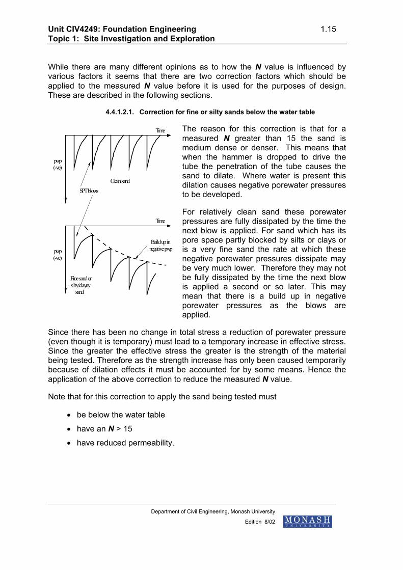
4.4.1.2.1. Correction for fine or silty sands below the water table
The reason for this correction is that for a measured N greater than 15 the sand is medium dense or denser. This means that when the hammer is dropped to drive the tube the penetration of the tube causes the sand to dilate. Where water is present this dilation causes negative porewater pressures to be developed.
pwp(-ve)
Time
Clean sandSPT blows
pwp(-ve)
Time
Fine sand orsilty/clayey
sand
Build up innegative pwp
For relatively clean sand these porewater pressures are fully dissipated by the time the next blow is applied. For sand which has its pore space partly blocked by silts or clays or is a very fine sand the rate at which these negative porewater pressures dissipate may be very much lower. Therefore they may not be fully dissipated by the time the next blow is applied a second or so later. This may mean that there is a build up in negative porewater pressures as the blows are applied.
Since there has been no change in total stress a reduction of porewater pressure (even though it is temporary) must lead to a temporary increase in effective stress. Since the greater the effective stress the greater is the strength of the material being tested. Therefore as the strength increase has only been caused temporarily because of dilation effects it must be accounted for by some means. Hence the application of the above correction to reduce the measured N value.
Note that for this correction to apply the sand being tested must
• be below the water table
• have an N > 15
• have reduced permeability.
Department of Civil Engineering, Monash University
Edition 8/02
Unit CIV4249: Foundation Engineering 1.16 Topic 1: Site Investigation and Exploration
4.4.1.2.2. Correction for shallow SPT results - Gibbs and Holtz
When correlations were nally made between SPT
N values and various engineering properties a major oversight (error?) was made. This oversight involved N values obtained at shallow depths. It was found that predictions of soil strength were unrealistically low and compressibility high. Therefore in order to correct this developed a correction factor which depended on the effective overburden pressure at the depth at which the test was carried out. This factor could then be
used with the original correlations (such as the correlation given above) to provide a more realistic value of N. Note that the correction factor is greater than 1 implying that the strength is greater than is suggested by the measured N value. It may also be worth noting that for effective overburden pressures greater than about 250 kPa the correction factor is 1 (i.e. the original correlation is reasonably accurate).
origi0
5 0
1 0 0
1 5 0
2 0 0
2 5 0
1 2 3C o r r e c t i o n =
4
c o r r e c t e d ' N ' v a l u em e a s u r e d 'N ' v a l u e
Effe
ctiv
e o
verb
urde
n p
ress
ure
, kP
a
C o r r e c t i o n fa c t o r s f o r s t a n d a r dp e n e t r a t i o n t e s t
( A f t e r G i b b s a n d H o l t z )
4.4.1.2.3. Kulhawy and Mayne Method
proposed an alternative method to interpret the results of SPT tests. This method establishes friction angle indirectly through sand relative density. This approach is recommended.
D C C C C C NC C Cr
ER B S R N
P A OCR
2 = , where
CER = , CB = , CS = , CR = , CN = , CP = , CA = , COCR = Two possible correlations between friction angle, φ, and relative density are shown in Kulhawy and Mayne.
Department of Civil Engineering, Monash University
Edition 8/02
Unit CIV4249: Foundation Engineering 1.17 Topic 1: Site Investigation and Exploration
4.4.1.3. Directly estimating settlement
Once N has been established, settlements can be (very approximately) estimated using the empirical Terzaghi and Peck curves to the left. It is important the curves are used for the following conditions.
• The allowable bearing pressure is for 25mm settlement with the water table below 2B for shallow strips and bases.
• For the water table immediately below the foundation the settlement is 50mm.
For a raft and water table below 2B depth, the graph is for 12mm settlement.
Width of foundation B- metres
600
500
400
300
200
100
0 1.5 2 3 4 5 6
N = 60
N = 50
N = 40
N = 30
N = 20
N = 10
N = 5
Loos
eM
ediu
mD
ense
Very
den
se
Allo
wab
le p
ress
ure
kPa
for
25
mm
tot
al s
ettle
men
t.W
ater
tab
le b
elow
dep
th 2
B
Chart for estimating allowable bearing pressure for foundations in sand on basis of results of standard penetration test (Terzaghi & Peck)
4.4.1.4. SPT correlations - Drained modulus
Empirical correlations between the (failure) SPT test and drained modulus for sands must be treated with caution. Nevertheless, these correlations can be used as primary estimators. Atmospheric pressure, pa can be assumed as 100 kPa. The value is the N value corrected to an average energy ratio of 60 percent (of rated energy).
Department of Civil Engineering, Monash University
Edition 8/02
Unit CIV4249: Foundation Engineering 1.18 Topic 1: Site Investigation and Exploration
E p NE p NE p N
a
a
a
≈
≈
≈
51015
60
60
60
sands with fines
clean NC sands
clean OC sands
tabulates some correlations of elastic parameters for granular soils based on N.
4.4.1.5. SPTs and undrained cohesion
SPT tests are generally performed in sands and gravels, however, there is no reason that they can’t be conducted in clays or silts. Correlations with undrained shear strength have been postulated - typically cu varies between 3N and 12N. See also for a very comprehensive summary of all the factors that can affect SPT tests, and recommendations for interpretation based on the work of others.
4.4.2. Static Cone Penetration Tests
A site investigation technique which has been extensively used in Europe and Australia since the 1970’s is the Cone Penetrometer Test. Its acceptance in the USA has been only limited. In this test, a probe is jacked into the ground at a constant penetration rate. This section briefly describes the test, its advantages and disadvantages, and its interpretation.
Department of Civil Engineering, Monash University
Edition 8/02
Unit CIV4249: Foundation Engineering 1.19 Topic 1: Site Investigation and Exploration
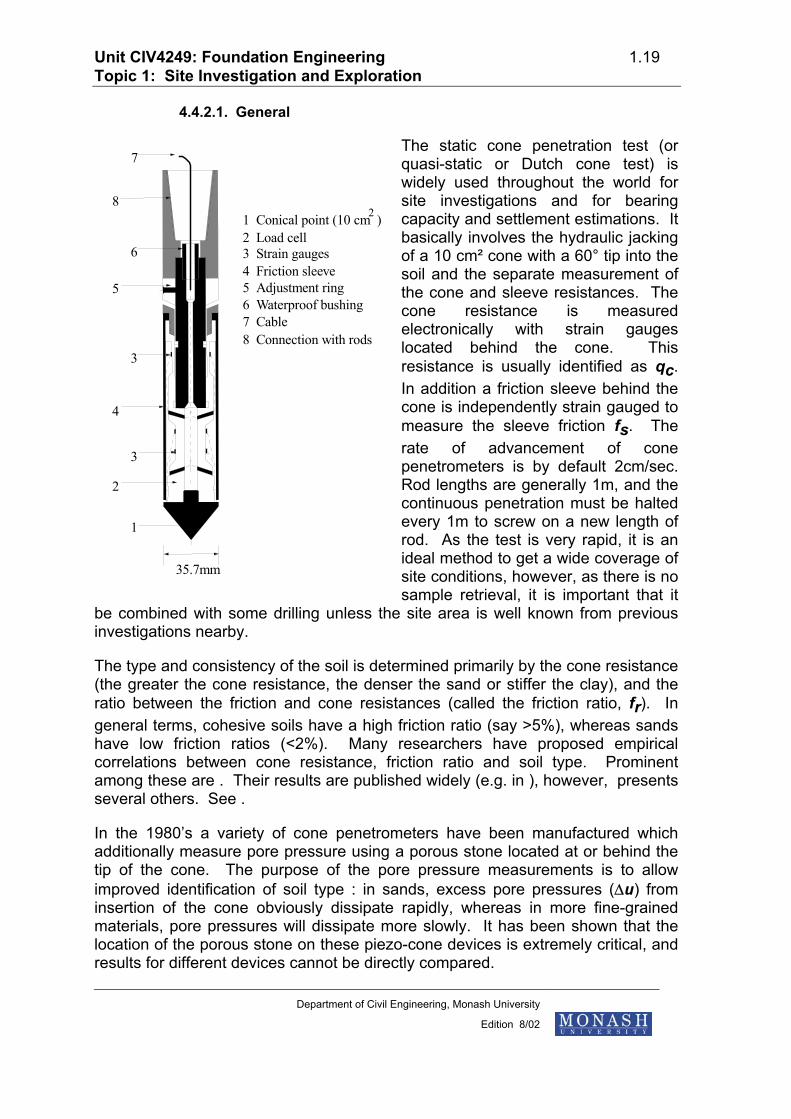
4.4.2.1. General
The static cone penetration test (or quasi-static or Dutch cone test) is widely used throughout the world for site investigations and for bearing capacity and settlement estimations. It basically involves the hydraulic jacking of a 10 cm² cone with a 60° tip into the soil and the separate measurement of the cone and sleeve resistances. The cone resistance is measured electronically with strain gauges located behind the cone. This resistance is usually identified as qc. In addition a friction sleeve behind the cone is independently strain gauged to measure the sleeve friction fs. The rate of advancement of cone penetrometers is by default 2cm/sec. Rod lengths are generally 1m, and the continuous penetration must be halted every 1m to screw on a new length of rod. As the test is very rapid, it is an ideal method to get a wide coverage of site conditions, however, as there is no sample retrieval, it is important that it
be combined with some drilling unless the site area is well known from previous investigations nearby.
The type and consistency of the soil is determined primarily by the cone resistance (the greater the cone resistance, the denser the sand or stiffer the clay), and the ratio between the friction and cone resistances (called the friction ratio, fr). In general terms, cohesive soils have a high friction ratio (say >5%), whereas sands have low friction ratios (<2%). Many researchers have proposed empirical correlations between cone resistance, friction ratio and soil type. Prominent among these are . Their results are published widely (e.g. in ), however, presents several others. See .
In the 1980’s a variety of cone penetrometers have been manufactured which additionally measure pore pressure using a porous stone located at or behind the tip of the cone. The purpose of the pore pressure measurements is to allow improved identification of soil type : in sands, excess pore pressures (∆u) from insertion of the cone obviously dissipate rapidly, whereas in more fine-grained materials, pore pressures will dissipate more slowly. It has been shown that the location of the porous stone on these piezo-cone devices is extremely critical, and results for different devices cannot be directly compared.
Department of Civil Engineering, Monash University
Edition 8/02
Unit CIV4249: Foundation Engineering 1.20 Topic 1: Site Investigation and Exploration
Original mechanical cone penetrometer systems involved the advancement of the cone with the sleeve static to measure qc and then the advancement of the sleeve to rejoin the cone to measure fs. This type of penetrometer is still referred to in texts, however, such devices are not used any more.
In summary, the CPT has the following advantages:
• It is quick and cheap to use. Many tests to quite reasonable depth may be accomplished in a day.
• It provides a continuous profile very quickly and therefore is an excellent method of obtaining detailed information between boreholes or identifying problem areas.
However it does have the disadvantages as follows:
• No soil sample seen.
• Usually should be calibrated alongside boreholes.
• Equipment can be costly.
• Troublesome with gravel and boulders.
4.4.2.2. CPT results
The results of cone penetrometer testing (qc, fs, fr and even ∆u) are typically plotted in real-time on paper tape, and may also be stored digitally. This method therefore allows a very quick appraisal of subsurface conditions
Department of Civil Engineering, Monash University
Edition 8/02
Unit CIV4249: Foundation Engineering 1.21 Topic 1: Site Investigation and Exploration
-5
-10
-15
-20
-25
-30
LEGEND:CLAY
SILT
SAND
GRAVEL
0.3 0.2 0.1 0 2 4 6 8 10 20 1O 5 0
SLEEVEFRICTION f(MPa)
sCONERESISTANCE q(MPa)
c INTE
RPR
ETED
SOIL
PRO
FILE
FRICTIONRATIO FR(%)
DEP
TH R
ELAT
ED T
O G
ROU
ND
LEV
EL I
N M
ETR
ES
4.4.2.3. Interpretation of cone penetrometers - soil type
Numerous CPT interpretations have been proposed. Two of the most widely accepted, and most recent are shown here:
Department of Civil Engineering, Monash University
Edition 8/02
Unit CIV4249: Foundation Engineering 1.22 Topic 1: Site Investigation and Exploration
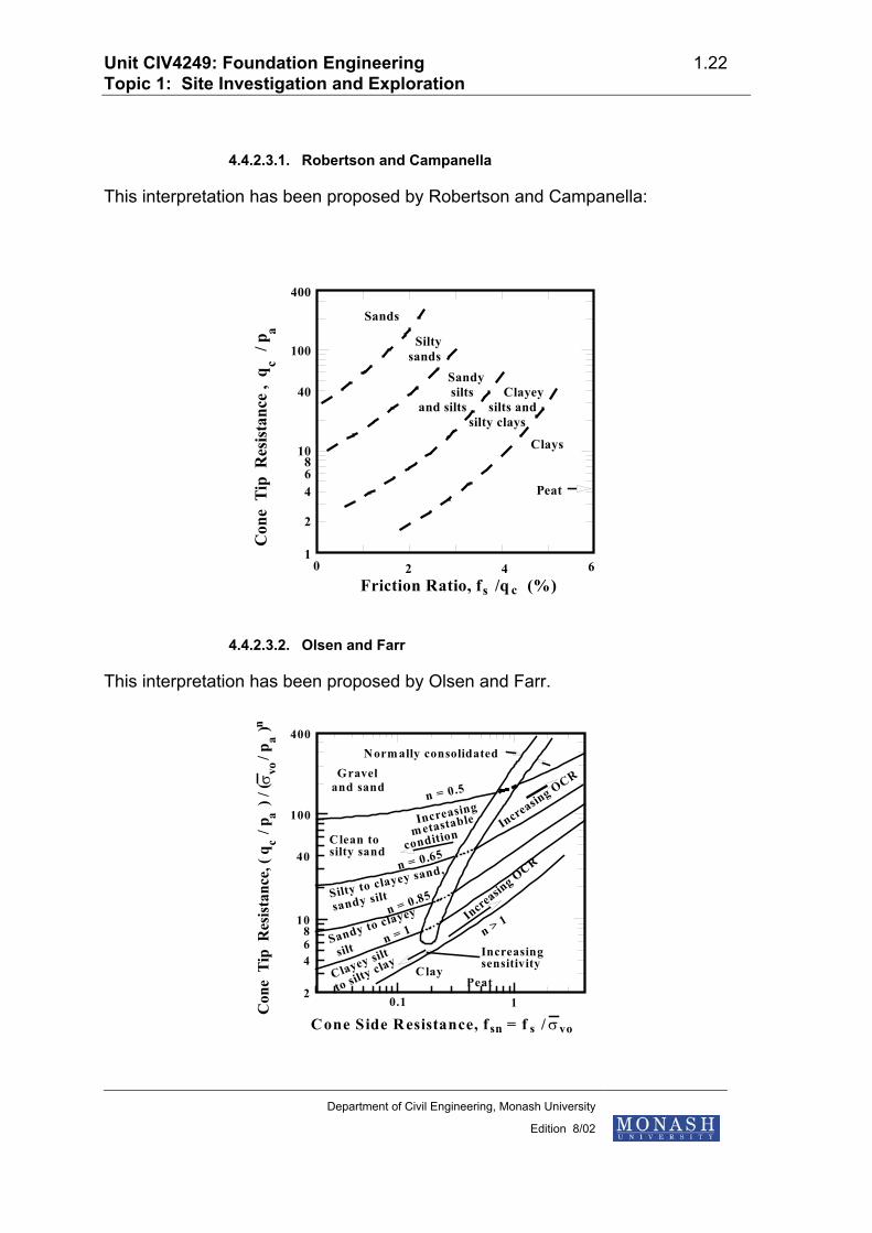
4.4.2.3.1. Robertson and Campanella
This interpretation has been proposed by Robertson and Campanella:
400
100
40
10
4
1
2
68
0 2 4 6Friction Ratio, f /q (%)s c
Con
e T
ip R
esis
tanc
e ,
q
/ pc
a
Sands
Siltysands
Sandysilts
and siltsClayey
silts andsilty clays
Clays
Peat
4.4.2.3.2. Olsen and Farr
This interpretation has been proposed by Olsen and Farr.
400
100
40
10
468
20.1 1
Norm ally consolidatedGravel
and sandn = 0.5
Increasing
metastable
conditionClean tosilty sand
Silty to clayey sand,
sandy silt
n = 0.65
n = 0.85
n = 1 n > 1
Clay
Increasin
g OCR
Increasing OCR
Peat
Sandy to clayey
silt
Clayey silt
to silty clay
Increasingsensitivity
Cone Side Resistance, f = f / σvossn
Con
e T
ip R
esis
tanc
e, (
q /
p
) / (
/
p
)σ vo
an
ca
Department of Civil Engineering, Monash University
Edition 8/02
Unit CIV4249: Foundation Engineering 1.23 Topic 1: Site Investigation and Exploration
4.4.2.4. Bearing Capacity
As the cone failure is a bearing capacity failure, the cone resistance, qc has a direct relationship to the ultimate bearing capacity. However, care must be exercised as scale can have a very large influence, especially if the soil contains fabric or other scale factors.
For shallow footings on sand, rather than use qc directly, it is more usual to use some of the existing correlations with friction angle, φ, and then establish bearing capacity by normal methods. in Figure 3-19 presents such an empirical relationship for uncemented quartz sands. Friction angle can also be determined indirectly through relative density and soil type using a number of empirical relationships summarized by .
For deep (piled) foundations in sand, it is usual to directly adopt weighted minimum values of qc within a distance of 8 diameters above the pile toe to 2 diameters below the pile toe. A number of such methods have been suggested, and some of these are detailed in . It should be noted that it is common to adopt a maximum end-bearing of 1.2 MPa for pile end bearing and 120 kPa for shaft resistance. For piles, the method of installation has a profound influence on pile capacity.
For shallow footings in clay, it is common to infer a value of undrained shear strength from the qc values and the total overburden stress, po. The following expression is used:
c q pNu
c o
k=
−
where Nk = cone factor (varies between 5 and 75, with values between 10 and 30 most common, and 15 to 20 most favoured).
The appropriate value for Nk for a particular site should be determined by correlation with undrained triaxial tests on clay samples.
4.4.2.5. Interpretation of cone penetrometers - settlement
There are many proposed methods for determination of settlement from CPT data. It must be emphasized that all must be empirical generalisations because the penetrometer by its very nature fails the soil, and therefore cannot measure anything other than parameters which relate to the ultimate condition. On the
Department of Civil Engineering, Monash University
Edition 8/02
Unit CIV4249: Foundation Engineering 1.24 Topic 1: Site Investigation and Exploration
other hand, structural settlement is related to a serviceability condition, and occurs hopefully long before failure occurs. The estimation of settlement from CPT results must therefore necessarily involve empirical correlation between the failure parameters and the likely settlement parameters such as modulus, Poisson's ratio etc.
One such method involves the estimation of a compressibility coefficient which is given by
C qp
c
o=
′α
The value α of is a function of many variables including the soil type. For sands, α is about 1.5, but for clays α is generally higher and in the range of about 1 to 8.
This coefficient is in turn used in the Buisman equation :
ρ =′ + ′
′
HC
p pp
o
oln ∆
where H is the thickness of the layer (or sub-layer) and ∆p′ is the change in effective stress in the layer caused by foundation loading.
4.4.2.6. CPT - SPT correlation
A useful correlation between SPT N value and qc has been proposed by Meyerhof as follows:
N qc=4
where qc is in kg/cm2
Later studies indicated that the ratio is actually dependent on the grain size of the material. proposes the following alternative relationship:
q p
NF
F
c a = −4 25413
..
where percent passing the No. 200 sieve (0.075mm or fine sand)=
also presents a similar relationship after .
4.4.3. Pressuremeter Tests
The pressuremeter is a probe which can be inserted in the ground and then inflated. It was originally developed in 1956 by as a relatively sophisticated
Department of Civil Engineering, Monash University
Edition 8/02
Unit CIV4249: Foundation Engineering 1.25 Topic 1: Site Investigation and Exploration
instrument for measuring the in-situ properties of soils. Both elastic properties of the ground and strength can be determined by measurement of the applied pressure and volume increase. Although the equipment is relatively expensive, its use in the field can be very economic with many tests being made in a working day. Also it can be used in a wide range of soils and rocks. There are basically two forms of the pressuremeter. One is installed in a prebored hole while the other is a self boring device.
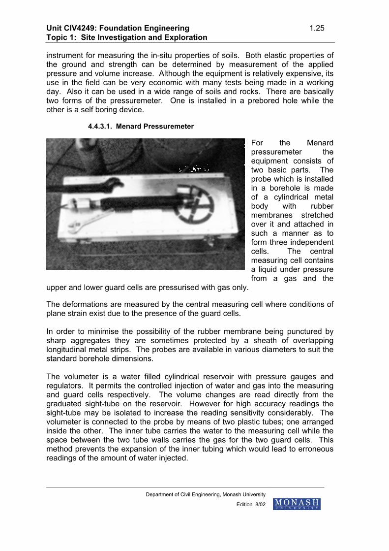
4.4.3.1. Menard Pressuremeter
For the Menard pressuremeter the equipment consists of two basic parts. The probe which is installed in a borehole is made of a cylindrical metal body with rubber membranes stretched over it and attached in such a manner as to form three independent cells. The central measuring cell contains a liquid under pressure from a gas and the
upper and lower guard cells are pressurised with gas only.
The deformations are measured by the central measuring cell where conditions of plane strain exist due to the presence of the guard cells. In order to minimise the possibility of the rubber membrane being punctured by sharp aggregates they are sometimes protected by a sheath of overlapping longitudinal metal strips. The probes are available in various diameters to suit the standard borehole dimensions. The volumeter is a water filled cylindrical reservoir with pressure gauges and regulators. It permits the controlled injection of water and gas into the measuring and guard cells respectively. The volume changes are read directly from the graduated sight-tube on the reservoir. However for high accuracy readings the sight-tube may be isolated to increase the reading sensitivity considerably. The volumeter is connected to the probe by means of two plastic tubes; one arranged inside the other. The inner tube carries the water to the measuring cell while the space between the two tube walls carries the gas for the two guard cells. This method prevents the expansion of the inner tubing which would lead to erroneous readings of the amount of water injected.
Department of Civil Engineering, Monash University
Edition 8/02
Unit CIV4249: Foundation Engineering 1.26 Topic 1: Site Investigation and Exploration
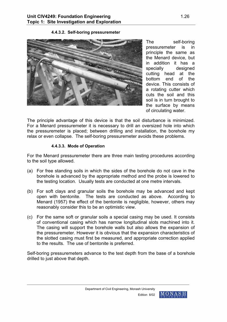
4.4.3.2. Self-boring pressuremeter
The self-boring pressuremeter is in principle the same as the Menard device, but in addition it has a specially designed cutting head at the bottom end of the device. This consists of a rotating cutter which cuts the soil and this soil is in turn brought to the surface by means of circulating water.
The principle advantage of this device is that the soil disturbance is minimized. For a Menard pressuremeter it is necessary to drill an oversized hole into which the pressuremeter is placed; between drilling and installation, the borehole my relax or even collapse. The self-boring pressuremeter avoids these problems.
4.4.3.3. Mode of Operation
For the Menard pressuremeter there are three main testing procedures according to the soil type allowed.
(a) For free standing soils in which the sides of the borehole do not cave in the borehole is advanced by the appropriate method and the probe is lowered to the testing location. Usually tests are conducted at one metre intervals.
(b) For soft clays and granular soils the borehole may be advanced and kept open with bentonite. The tests are conducted as above. According to Menard (1957) the effect of the bentonite is negligible, however, others may reasonably consider this to be an optimistic view.
(c) For the same soft or granular soils a special casing may be used. It consists of conventional casing which has narrow longitudinal slots machined into it. The casing will support the borehole walls but also allows the expansion of the pressuremeter. However it is obvious that the expansion characteristics of the slotted casing must first be measured, and appropriate correction applied to the results. The use of bentonite is preferred.
Self-boring pressuremeters advance to the test depth from the base of a borehole drilled to just above that depth.
Department of Civil Engineering, Monash University
Edition 8/02
Unit CIV4249: Foundation Engineering 1.27 Topic 1: Site Investigation and Exploration
4.4.3.4. Phases of the test
Once the pressuremeter has been installed at its test location the zero readings are taken with the pressuremeter sides just touching the soil. Then the pressure in the cells is increased to a preselected value, a small fraction (2.5% to 10%) of the estimated maximum. Once the pressure has been achieved the volume readings at 15, 30 and 60 seconds are taken. The pressure is then progressively increased, with the same readings being taken at each pressure. The volume changes at 60 seconds are plotted against pressure during the test, and the net result is effectively a stress/strain curve, as shown.
CORRECTED CELL PRESSURE, P
1 2 3
Expansion of probePseudo elastic
behaviourPlastic
behaviour
CEL
L V
OLU
ME
INC
REA
SE
v ∆
P o P f P l
There are three basic stages involved in the deformation of the soil. Stage 1 (up to Po ) consists of the recompression of the soil to the in-situ stress before the borehole was made.
Stage 2 (Po to Pf ) consists of the elastic deformation of the soil adjacent to the measuring cell. This is characterised by a straight line plot of the pressure/volume curve. The elastic modulus E is usually derived from this section of the curve. Stage 3 (Pf to Pl ) is equivalent to the plastic deformation of the soil in which the volume change increases until at the limit pressure Pl the soil fails.
By plotting the volume change between 30 and 60 seconds the "creep curve" is obtained. It represents the tendency of the material to creep. The point at which a definite upward break occurs is referred to as the creep pressure Pf and it generally corresponds to the upper limit of the elastic deformation range.
Department of Civil Engineering, Monash University
Edition 8/02
Unit CIV4249: Foundation Engineering 1.28 Topic 1: Site Investigation and Exploration
4.4.3.5. Determination of elastic parameters
The pressuremeter may be used to evaluate the properties of most soil and soft rock types. However because the test is relatively quick, the analysis is usually based on undrained parameters for cohesive soils and drained parameters for granular soils. Obviously for soils containing a significant portion of silt sized particles or for rocks containing significant porous fabric such as fissures and joints, it may not be clear what type of parameter is being derived by the test.
The appropriate elastic modulus (drained or undrained) of the soil or rock is evaluated from the linear portion of the pressure-volume curve. The modulus is given by the expression:
E V PV
V PPV
o
o o
= +
==
=
2 1( )ν
ν
∆∆
∆∆
where Poissons ratio
Volume at pressure
and slope of linear portion
It is important to remember that the elastic properties determined by pressuremeter tests are lateral values, and that unless the soil is isotropic, the derived values will be different from the vertical values because of the manner in which soils are laid down over time. As the elastic values needed for footing settlement calculations are vertical, these values may be inappropriate. Pressuremeter results are more appropriate for piles which may be laterally loaded. Poisson’s ratio is by definition 0.5 for undrained loading, but must be estimated for drained loading.
4.4.3.6. Determination of strength parameters
The strength of soils may also be estimated from the pressuremeter test result. However in simple terms it is only possible to evaluate cu for undrained cohesive soils and φ' for drained granular soils. When a soil possesses both c' and φ' (e.g. rocks or mixed soils) a variety of complex testing procedures must be undertaken.
For cohesive soils tested in undrained conditions the undrained cohesion may be approximated by the expression
c P P
N
N E
ul o
p
p u
=−
= +where 1 3ln( )c
report that Np may vary between 2 and 20, however it is generally in the range 5 to 12, with an average of 8.5.
Department of Civil Engineering, Monash University
Edition 8/02
Unit CIV4249: Foundation Engineering 1.29 Topic 1: Site Investigation and Exploration
For granular soils, fully drained conditions are assumed and φ' is evaluated. According to the original Gibson and Anderson (1961) analysis, at failure the ratio of circumferential stress to radial stress is given by
′′
=−+
=σσ
φφ
θ
rN1
1sinsin
[N.B. Not the N as applies to SPT tests.]
The pressure-volume relationship is given by
′ =′
+
′ +
+−
−
P PN
EP
NN
VV
o
o
N21 2 1
11
1 2 1
( )
/ ( )
ν∆
Therefore when plotting log (∆V/V) against log P′ a reasonably straight line is obtained for the plastic region. The slope of this line is 1/2(1-N) and therefore φ' may be calculated.
An alternative approach for determination of φ' after is presented in .
4.4.3.7. Closing comments
While the above simple treatment of the pressuremeter analysis has been presented, there are still a great number of factors which influence the test results and which are not fully understood yet.
These factors include the following:
• The influence of soil dilation;
• The influence of tensile stresses in the circumferential direction especially with regard to tensile cracking;
• The influence of porewater pressures;
• Drainage conditions;
• Soil variability and anisotropy;
• Loading in a horizontal plane.
The pressuremeter was initially seen as the answer to all geotechnical problems, but over time it has taken a more sensible position as one of a number of less than perfect tools which are available to the geotechnical engineer. Pressuremeter tests are used quite extensively for larger projects where the cost of this type of test can be justified.
Department of Civil Engineering, Monash University
Edition 8/02
Unit CIV4249: Foundation Engineering 1.30 Topic 1: Site Investigation and Exploration
4.4.4. Dilatometer Tests
The dilatometer is a blade which can be hydraulically jacked into the base of a borehole, or pushed with a CPT rig. The test was developed by . The blade contains a 60mm diameter membrane which is expanded laterally by 1.1mm against the soil. Pressures at “lift-off” at full expansion and again when flush with the blade surface are taken. These pressures are variously combined to give a dilatometer modulus index, ED, a lateral stress index, KD, and a material or deposit index, ID.
According to Marchetti, the test can be used to determine the full range of strength and compressibility parameters (E, Ko, OCR, cu, φ, and mv). However, it must always be borne in mind that insertion of the probe causes soil disturbance and failure, and the derivation of elastic parameters and peak strength parameters are therefore indirect and empirically based.
Dilatometer testing has been available in Australia since the late 1980’s. Interpretation of dilatometer tests is covered in , and . Proponents of this method claim that it can be used to establish both strength and compressibility parameters, however, it must be remembered that like all in-situ tests, insertion of the device is actually failing and changing the soil.
4.4.5. Vane Tests
The vane shear test is a method used predominantly in soft clays to estimate in-situ shear strength. The cruciform section vane is generally pushed into the soil at the base of the borehole, however, it can also be pushed from the surface with a protective sheath. The vanes can be of different widths and lengths to allow a broad range of soil strengths to be tested. Once in place, the vane is rotated at a constant rotational speed of 6°/minute, and the maximum and residual torque achieved is recorded.
The applied torque or moment, T, to turn the vane is related to the undrained strength of a soft clay, su by
T s d auh d= +π 22 4( )
where h is the height of the vane, d is the diameter and a is a constant for the user-assumed end shear. It is usually taken as 2/3 for uniform end shear, but can be as low as 1/2 for a triangular assumption, or 3/5 for parabolic end shear.
Insensitive clays do not display substantial differences between peak and residual torque. Conversely, these values may be an order of magnitude or more different for highly sensitive clays.
Department of Civil Engineering, Monash University
Edition 8/02
Unit CIV4249: Foundation Engineering 1.31 Topic 1: Site Investigation and Exploration
4.4.6. Field Permeability Tests
Foundation permeability tests include both in-situ permeability tests and permeability tests on samples retrieved from the boreholes for laboratory testing. Although the in-situ tests have advantages in that tests encompass the global response of the soil, with soil fabric relatively undisturbed, interpretation can be confused when the soil is distinctly layered, or boundary conditions do not match the simplified model in some other way.
By contrast, laboratory permeability tests can isolate the permeability of a particular soil, however, the effect of soil fabric is often lost in the necessarily small samples.
Some in-situ tests include the and the . Permeability tests are not an issue with foundations unless the foundations require an excavation below potential water-table level. In-situ test are:
• Necessary in variable or stratified soils.
• Generally not difficult to perform but difficult to interpret.
4.4.7. Applicability of Test Methods
The previous sections have described a number of in-situ testing methods that are available to the geotechnical engineer. This is by no means an exhaustive list of possible tools, but covers the principle tools used for typical site investigations. tabulated an extensive range of geotechnical tests and their applicability to the determination of the following - see Table 3-2.
• Soil identification
• Establish vertical profile
• Relative Density
• Angle of friction
• Undrained shear strength
• Pore pressure
• Stress history and Ko
• Modulus
• Compressibility parameters
• Consolidation parameters
• Permeability
• Stress-strain response
• Liquefaction resistance
Department of Civil Engineering, Monash University
Edition 8/02
Unit CIV4249: Foundation Engineering 1.32 Topic 1: Site Investigation and Exploration
Not surprisingly, the self-boring pressuremeter, which Wroth developed, emerges as one of the best investigation tools in all categories. The piezo-cone devices also rate highly. It must be remembered that both devices, but particularly the self boring pressuremeter are highly specialized pieces of equipment that are not readily available, and are expensive to use. Their use must be consistent with the available budget and the criticalness of the structure.
4.5. Sampling
Samples fall into two broad categories - disturbed and undisturbed. The key features of each of these categories will be discussed hereafter.
4.5.1. "Disturbed" Sample
• A by-product of most operations.
• Structure and often moisture content considerably altered from insitu state. In certain cases, contamination from different strata occur (e.g. flight auger).
• Give some definition of changes in strata.
• Used in laboratory for visual classification and mechanical analysis index determination (e.g. liquid and plastic limit).
• The amount of disturbance varies. The returned wash from the wash boring process is extremely disturbed; the sample obtained during an SPT is significantly disturbed.
• Handling is important. When obtained samples should be placed immediately in airtight jars tins plastic bags etc. labelled to identify the job number, locality, bore no. depth and date of sampling and sent to lab.
4.5.2. "Undisturbed" Samples
• Samples in which the insitu structure and moisture content have been as far possible completely preserved.
• No sample truly "undisturbed" because of stress release on sampling.
• In stiff and over-consolidated clays, sampling not likely to significantly affect the 'design properties' of soil.
• In soft and sensitive clays sampling disturbance considerably reduces measured strength, E etc. and increases compressibility.
• In sands, usually significantly alters voids ratio (undisturbed samples are rarely attempted in sands);
• Simplest method of obtaining undisturbed samples is pressing a thin walled tube into the soil i.e. an open drive sampler.
• Sampler should not be driven into the soil but pressed in, preferably at a constant rate of penetration.
Department of Civil Engineering, Monash University
Edition 8/02
Unit CIV4249: Foundation Engineering 1.33 Topic 1: Site Investigation and Exploration
• Open drive samplers commonly around 50 mm and 75 mm inside diameter. L/D ratios vary from about 6 to 18.
• To avoid disturbing soil the borehole should be cleaned out before sampling (e.g. with auger or by jetting). Sample ahead of earlier boring. Also maintain ground water balance. In soft and sensitive soils the thin walled piston sampler gives best samples. Floating or stationary types of piston. Tube forced into ground with piston blocking off end. At required depth piston is released from ground level and sampler advanced over the piston. Enables samples to considerable depths in soft clays without casing. In variable or very hard soils above types no use. Use coring triple tube barrel etc. See CSIRO Soil Mechanics Section Technical Report No. 2.
• In order to obtain "undisturbed" samples construction of sampler must be appropriate. Critical parameter is the area ratio which is defined as :
D D
Dmax min
min
2 2
2−
• Large area ratio gives large disturbance. However strength requirement defines minimum area ratio. AS1726 states that area ratio must not exceed 10% with a cutting edge not exceeding 5° to the axis of the sampler.
5. SITE EXPLORATION PLANNING Depends on many previously mentioned variables such as existing knowledge anticipated site conditions and accessibility type of structure and its sensitivity to ground movements proposed means of construction financial limitations etc.
In general it will be necessary to specify at least the following information:
• number and type of holes (bores or penetrometers etc.); • their required locations and depth; • frequency and type of sampling in each hole; • subsequent treatment of samples handling and transport precautions; • field and laboratory testing required; • extent of supervision of drilling and testing.
Department of Civil Engineering, Monash University
Edition 8/02
Unit CIV4249: Foundation Engineering 1.34 Topic 1: Site Investigation and Exploration
Tables such as the ones provided can give a useful guide to planning the most effective site exploration.
It should be emphasised however that there should be effective communication between the field engineer, the design engineer and the client so that should any modifications to the exploration programme be necessary they can be made without undue waste of time or confusion.
6. SITE INVESTIGATION REPORTS It is of considerable importance that the report which is produced at the culmination of site investigation is complete and comprehensive and conveys the information required in clear and effective terms.
It is vitally important that all significant aspects of the site investigation are covered in relation to the proposed development so that the next phase of the development (probably the design work) may be satisfactorily carried out. Remember that the report is generally a legal document and any gross misinterpretation of data may lead to legal proceedings!
The report will also be a record for use in the future should any defect or unfavourable condition develop during the life of the development. The report may also be used for assessing any future extensions or modifications to the original development.
Should any possible source of concern appear during the investigations this should also be reported and any recommendation as to its solution should be included.
A clear distinction between factual data and interpretations should be maintained throughout the report.
It is also important that the report contains a clear identification of the site and the location of the boreholes test pits etc. All borehole logs and tests results should also be included preferably in standard tabular form. Cross-sections are always a good way of illustrating the soil stratification.
A good report should include plenty of diagrams and figures which always speak louder than words.
Remember that the report is the final and probably the only product of the site investigation and generally since it represents a considerable amount of time energy and cost it is worth doing well.
7. GLOSSARY Aging Correction Factor
For SPTs = 1.2 + 0.05 log (t/100) , where t is age of deposit in years. Department of Civil Engineering, Monash University
Edition 8/02
Unit CIV4249: Foundation Engineering 1.35 Topic 1: Site Investigation and Exploration
Borehole Diameter Correction Factor
For SPT tests = 1.0 for 65 to 115 mm diameter boreholes = 1.05 for 150 mm diameter boreholes = 1.15 for 200 mm diameter boreholes
Energy Ratio Correction Factor
For SPTs: = 0.9 for safety hammer = 0.75 for donut hammer (usu. in U.S.)
Fixed-head Packer Tests
Field permeability tests in which a section of borehole is isolated with inflatable packers, and subjected to a constant pressure head. The volume of flow required to maintain the pressure can be used to determine in-situ permeability.
Overburden Stress Correction Factor
For SPTs , where pa= atmospheric pressure (in kPa) = +2 1/ ( / )σo’ pa
Overconsolidation Correction Factor
For SPTs = OCR0.18
See
Overconsolidation Ratio
Abbreviated as OCR. The ratio of maximum past effective to the current effective overburden stress. Greater than or equal to 1.
Particle Size Correction Factor
For SPTs = 60 + 25 log D50 , where D50 is in mm.
Pumping Tests
Pumping tests are a form of in-situ permeability test in which water is pumped out at a constant rate from a borehole with a perforated (PVC) casing. The rate of drawdown of water level in adjacent observation wells is used to determine average permeability. See pp. 109-112.
Rod Length Correction Factor
Department of Civil Engineering, Monash University
Edition 8/02
Unit CIV4249: Foundation Engineering 1.36 Topic 1: Site Investigation and Exploration
For SPTs = 1.0 for rod length > 10m = 0.95 for rod length 6 to 10m = 0.85 for rod length 4 to 6m = 0.75 for rod length 3 to 4m
Sampling Method Correction Factor
For SPTs = 1.0 for a standard sampler = 1.2 for a sampler without a liner
8. REFERENCES Bowles, J.E., (1988)
Foundation analysis and design. 4th ed. McGraw-Hill.
Das, B.M., (1990a)
Principles of geotechnical engineering. 2nd ed. PWS-Kent Publishing Company, Boston.
Das, B.M. (1990b)
Principles of Foundation Engineering. 2nd ed. PWS-Kent Publishing Company, Boston.
Clayton C.R.I. Simons N.E. and Matthews M.C. (1982)
Site Investigation A Handbook for Engineers" Granada Publishing 1982.
Ervin M.C. (1983)
Insitu testing for geotechnical investigations. A.A.Balkema (ed),1983.
Gibbs, H.J. and Holtz, W.G. (1957)
Research on determining the density of sands by spoon penetration testing. 4th ICSMFE, Vol. 1 : 35 - 39.
Department of Civil Engineering, Monash University
Edition 8/02
Unit CIV4249: Foundation Engineering 1.37 Topic 1: Site Investigation and Exploration
Department of Civil Engineering, Monash University
Edition 8/02
Manual on estimating soil properties for foundation design. Report EPRI EL-6800 for Electric Power Research Institute.
Mair, R.J. and Wood, D.M. (1987)
Pressuremeter Testing. Butterworths, London.
Marchetti, S. (1980)
In-situ tests by flat dilatometer. Jnl. Geotechnical Engineering Div., ASCE, Vol. 106, GT3, March : 299 - 321.
Menard, L. (1956)
An apparatus for measuring the strength of soils in place. M.Sc Thesis, University of Illinois, Urbana, IL.
Meyerhof, G.G. (1956)
Penetration tests and bearing capacity of cohesionless soils. JSMFD, ASCE Vol 82, SM 1 : 1-19.
Olsen, R.S. and Farr, J.V. (1986)
Site characterization using the cone penetrometer test. Use of in-situ tests in Geotechnical engineering. Geotechnical Special Publication No. 6, Ed. S.P. Clemence, ASCE : 854 - 868.
Peck, R.B., Hansen, W.E. and Thorburn, T.H. (1974)
Foundation Engineering. 2nd ed. John Wiley and Sons. New York, 514 pp.
Robertson, P.K. and Campanella, R.G. (1983)
Interpretation of cone penetrometer tests, Part 1 : sand. Canadian Geotechnical Journal, Vol. 20, No. 4 : 718 - 733.
Rowe, P.W. (1972)
The relevance of soil fabric to site investigation practice. Geotechnique June 1972
Terzaghi, K. And Peck, R.B. (1967)
Soil Mechanics in Engineering Practice. 2nd ed. John Wiley and Sons, New York.