Maintenance Manual Site Master™ S331L Handheld Cable and Antenna Analyzer Featuring Classic and Advanced Modes 2 MHz to 4 GHz Cable & Antenna Analyzer 50 MHz to 4 GHz Power Meter Anritsu Company 490 Jarvis Drive Morgan Hill, CA 95037-2809 USA Part Number: 10580-00323 Revision: B Published: August 2012 Copyright 2012 Anritsu Company
Transcript
Maintenance Manual
Site Master™ S331L Handheld Cable and Antenna Analyzer Featuring Classic and Advanced Modes
2 MHz to 4 GHz Cable & Antenna Analyzer50 MHz to 4 GHz Power Meter
Anritsu Company490 Jarvis DriveMorgan Hill, CA 95037-2809USA
Part Number: 10580-00323Revision: B
Published: August 2012Copyright 2012 Anritsu Company
TRADEMARK ACKNOWLEDGMENTSWindows, Windows XP, and Windows CE are all registered trademarks of Microsoft Corporation.Acrobat Reader is a registered trademark of Adobe Corporation.Site Master is a trademark of Anritsu Company.
NOTICEAnritsu Company has prepared this manual for use by Anritsu Company personnel and customers as a guide for theproper installation, operation and maintenance of Anritsu Company equipment and computer programs. Thedrawings, specifications, and information contained herein are the property of Anritsu Company, and anyunauthorized use or disclosure of these drawings, specifications, and information is prohibited; they shall not bereproduced, copied, or used in whole or in part as the basis for manufacture or sale of the equipment or softwareprograms without the prior written consent of Anritsu Company.
UPDATESUpdates, if any, can be downloaded from the Documents area of the Anritsu Website at:http://www.anritsu.com
For the latest service and sales contact information in your area, please visit:http://www.anritsu.com/contact.asp
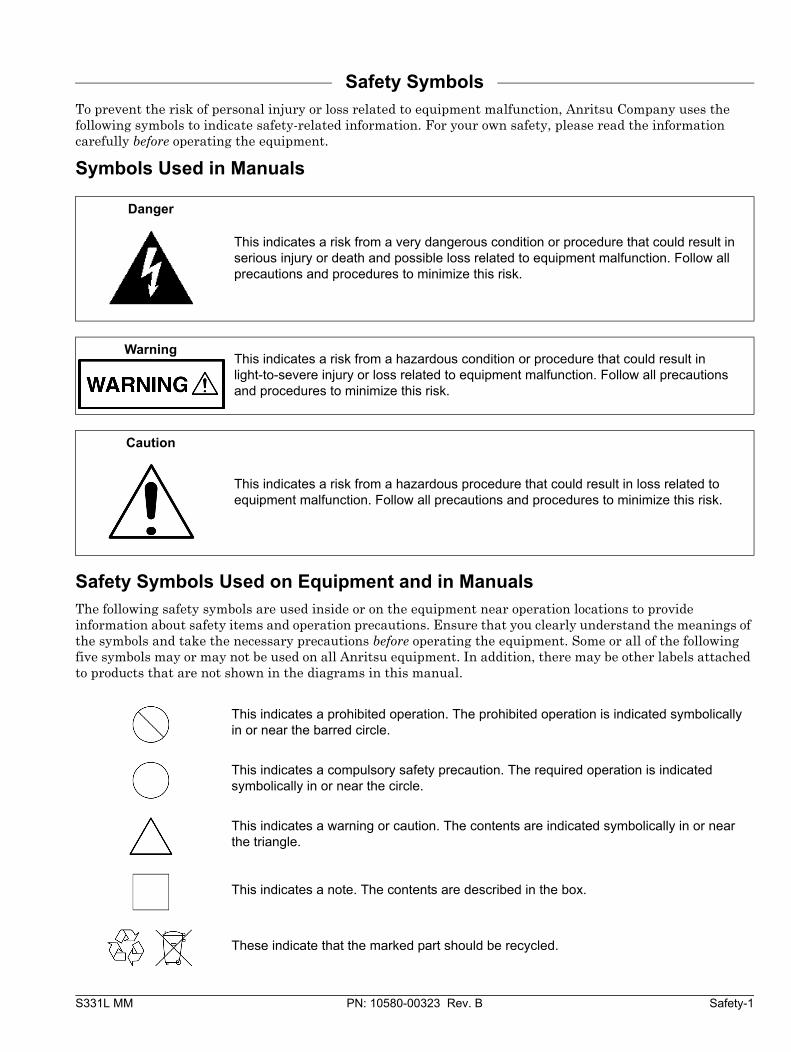
Safety SymbolsTo prevent the risk of personal injury or loss related to equipment malfunction, Anritsu Company uses the following symbols to indicate safety-related information. For your own safety, please read the information carefully before operating the equipment.
Symbols Used in Manuals
Safety Symbols Used on Equipment and in ManualsThe following safety symbols are used inside or on the equipment near operation locations to provide information about safety items and operation precautions. Ensure that you clearly understand the meanings of the symbols and take the necessary precautions before operating the equipment. Some or all of the following five symbols may or may not be used on all Anritsu equipment. In addition, there may be other labels attached to products that are not shown in the diagrams in this manual.
Danger
This indicates a risk from a very dangerous condition or procedure that could result in serious injury or death and possible loss related to equipment malfunction. Follow all precautions and procedures to minimize this risk.
WarningThis indicates a risk from a hazardous condition or procedure that could result in light-to-severe injury or loss related to equipment malfunction. Follow all precautions and procedures to minimize this risk.
Caution
This indicates a risk from a hazardous procedure that could result in loss related to equipment malfunction. Follow all precautions and procedures to minimize this risk.
This indicates a prohibited operation. The prohibited operation is indicated symbolically in or near the barred circle.
This indicates a compulsory safety precaution. The required operation is indicated symbolically in or near the circle.
This indicates a warning or caution. The contents are indicated symbolically in or near the triangle.
This indicates a note. The contents are described in the box.
These indicate that the marked part should be recycled.
Safety-2 PN: 10580-00323 Rev. B S331L MM
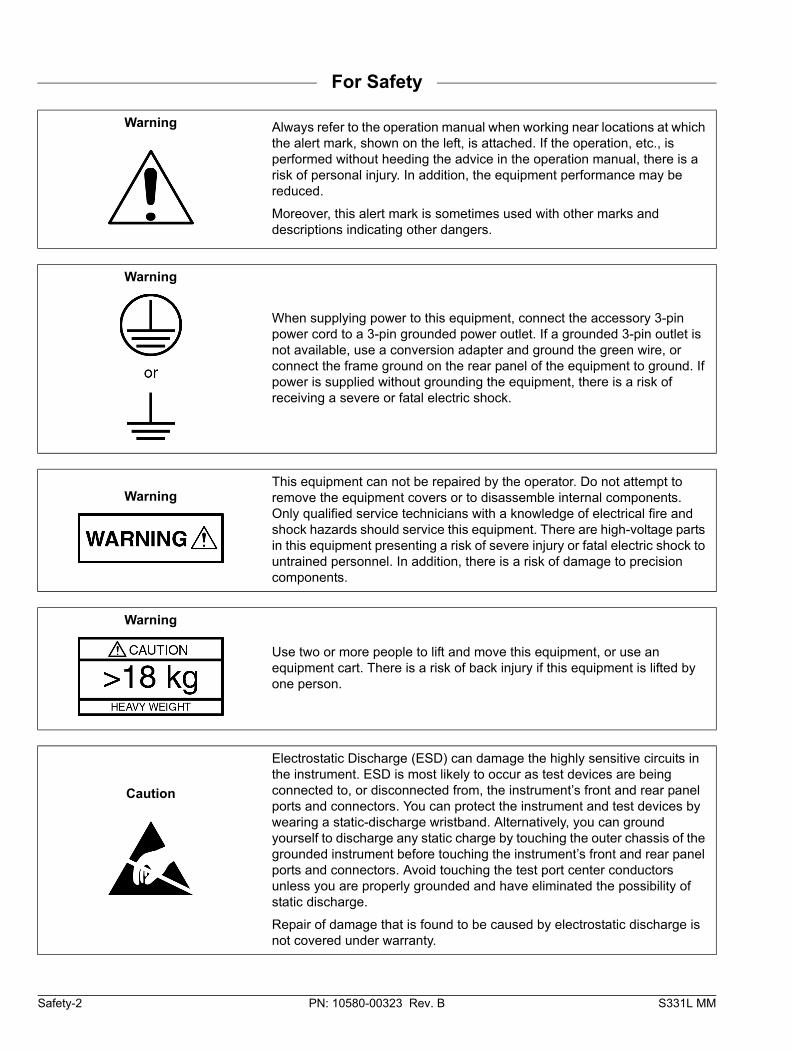
For Safety
Warning Always refer to the operation manual when working near locations at which the alert mark, shown on the left, is attached. If the operation, etc., is performed without heeding the advice in the operation manual, there is a risk of personal injury. In addition, the equipment performance may be reduced.
Moreover, this alert mark is sometimes used with other marks and descriptions indicating other dangers.
Warning
When supplying power to this equipment, connect the accessory 3-pin power cord to a 3-pin grounded power outlet. If a grounded 3-pin outlet is not available, use a conversion adapter and ground the green wire, or connect the frame ground on the rear panel of the equipment to ground. If power is supplied without grounding the equipment, there is a risk of receiving a severe or fatal electric shock.
WarningThis equipment can not be repaired by the operator. Do not attempt to remove the equipment covers or to disassemble internal components. Only qualified service technicians with a knowledge of electrical fire and shock hazards should service this equipment. There are high-voltage parts in this equipment presenting a risk of severe injury or fatal electric shock to untrained personnel. In addition, there is a risk of damage to precision components.
Warning
Use two or more people to lift and move this equipment, or use an equipment cart. There is a risk of back injury if this equipment is lifted by one person.
Caution
Electrostatic Discharge (ESD) can damage the highly sensitive circuits in the instrument. ESD is most likely to occur as test devices are being connected to, or disconnected from, the instrument’s front and rear panel ports and connectors. You can protect the instrument and test devices by wearing a static-discharge wristband. Alternatively, you can ground yourself to discharge any static charge by touching the outer chassis of the grounded instrument before touching the instrument’s front and rear panel ports and connectors. Avoid touching the test port center conductors unless you are properly grounded and have eliminated the possibility of static discharge.
Repair of damage that is found to be caused by electrostatic discharge is not covered under warranty.
• Copy the blank test records from Appendix A and use them to record measured values. These test records form a record of the performance of your instrument. Anritsu recommends that you make a copy of the blank test records to document the measurements each time a Performance Verification is performed. Continuing to document this process each time it is performed provides a detailed history of instrument performance, which can allow you to observe trends.
Familiarity with the basic operation of the front panel keys (for example, how to change measurement mode, preset the unit, or the meaning of soft key or submenu) is assumed. Refer to the instrument’s User Guide for additional information.
1-2 Anritsu Customer Service CentersFor the latest service and sales information in your area, please visit the following URL:
http://www.anritsu.com/contact.asp
From here, you can select the latest sales, select service and support contact information in your country or region, provide online feedback, complete a “Talk to Anritsu” form to have your questions answered, or obtain other services offered by Anritsu.
Updated product information can be found on the Anritsu web site:
http://www.anritsu.com/
Search for the product model number. The latest documentation is on the product page under the Library tab.
1-3 Recommended Test Equipment General Information
1-2 PN: 10580-00323 Rev. B S331L MM
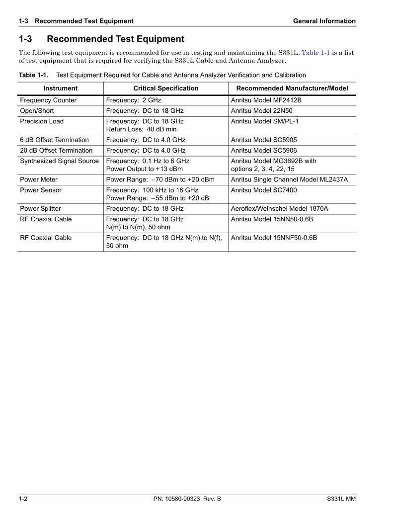
1-3 Recommended Test EquipmentThe following test equipment is recommended for use in testing and maintaining the S331L. Table 1-1 is a list of test equipment that is required for verifying the S331L Cable and Antenna Analyzer.
Table 1-1. Test Equipment Required for Cable and Antenna Analyzer Verification and Calibration
Frequency Counter Frequency: 2 GHz Anritsu Model MF2412B
Open/Short Frequency: DC to 18 GHz Anritsu Model 22N50
Precision Load Frequency: DC to 18 GHzReturn Loss: 40 dB min.
Anritsu Model SM/PL-1
6 dB Offset Termination Frequency: DC to 4.0 GHz Anritsu Model SC5905
20 dB Offset Termination Frequency: DC to 4.0 GHz Anritsu Model SC5906
Synthesized Signal Source Frequency: 0.1 Hz to 6 GHzPower Output to +13 dBm
Anritsu Model MG3692B with options 2, 3, 4, 22, 15
Power Meter Power Range: −70 dBm to +20 dBm Anritsu Single Channel Model ML2437A
Power Sensor Frequency: 100 kHz to 18 GHzPower Range: –55 dBm to +20 dB
Anritsu Model SC7400
Power Splitter Frequency: DC to 18 GHz Aeroflex/Weinschel Model 1870A
RF Coaxial Cable Frequency: DC to 18 GHz N(m) to N(m), 50 ohm
Anritsu Model 15NN50-0.6B
RF Coaxial Cable Frequency: DC to 18 GHz N(m) to N(f), 50 ohm
Anritsu Model 15NNF50-0.6B
General Information 1-4 Replaceable Parts
S331L MM PN: 10580-00323 Rev. B 1-3
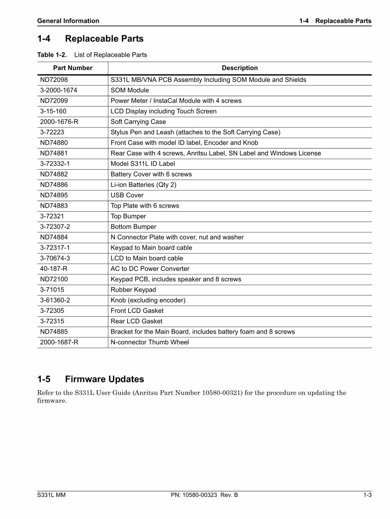
1-4 Replaceable Parts
1-5 Firmware UpdatesRefer to the S331L User Guide (Anritsu Part Number 10580-00321) for the procedure on updating the firmware.
Table 1-2. List of Replaceable Parts
Part Number Description
ND72098 S331L MB/VNA PCB Assembly Including SOM Module and Shields
3-2000-1674 SOM Module
ND72099 Power Meter / InstaCal Module with 4 screws
3-15-160 LCD Display including Touch Screen
2000-1676-R Soft Carrying Case
3-72223 Stylus Pen and Leash (attaches to the Soft Carrying Case)
ND74880 Front Case with model ID label, Encoder and Knob
ND74881 Rear Case with 4 screws, Anritsu Label, SN Label and Windows License
3-72332-1 Model S311L ID Label
ND74882 Battery Cover with 6 screws
ND74886 Li-ion Batteries (Qty 2)
ND74895 USB Cover
ND74883 Top Plate with 6 screws
3-72321 Top Bumper
3-72307-2 Bottom Bumper
ND74884 N Connector Plate with cover, nut and washer
3-72317-1 Keypad to Main board cable
3-70674-3 LCD to Main board cable
40-187-R AC to DC Power Converter
ND72100 Keypad PCB, includes speaker and 8 screws
3-71015 Rubber Keypad
3-61360-2 Knob (excluding encoder)
3-72305 Front LCD Gasket
3-72315 Rear LCD Gasket
ND74885 Bracket for the Main Board, includes battery foam and 8 screws
2000-1687-R N-connector Thumb Wheel
1-5 Firmware Updates General Information
1-4 PN: 10580-00323 Rev. B S331L MM
S331L MM PN: 10580-00323 Rev. B 2-1
Chapter 2 — S331L Performance Verification
2-1 IntroductionThese tests verify the Cable and Antenna Analyzer, Power Meter and InstaCal functionality on the S331L Site Master.The functional tests include:
• “Frequency Accuracy Verification” on page 2-1
• “Return Loss Accuracy Verification” on page 2-2
• “Power Meter Verification” on page 2-3
• “InstaCal Verification” on page 2-5
2-2 Frequency Accuracy VerificationThe following test is used to verify the CW frequency accuracy of the S331L’s RF Source in Cable and Antenna Analyzer mode.
Equipment Required
• Frequency Counter Frequency: 2 GHz Anritsu Model MF2412B
• RF Coaxial Cable Freq: DC to 18 GHz, N(m) to N(m), 50 Ohm, Anritsu Model 15NN50-0.6B
Procedure
1. Verify that the S331L is in Cable and Antenna Analyzer mode and preset the unit.
2. Press ESC then the Sweep (3) key.
3. Verify that the RF Immunity is set to High.
4. Press the Freq/Dist menu key and set both the Start Freq and Stop Freq to 1 GHz.
5. Connect the RF cable from the S331L RF Out/Reflect In to the Frequency Counter.
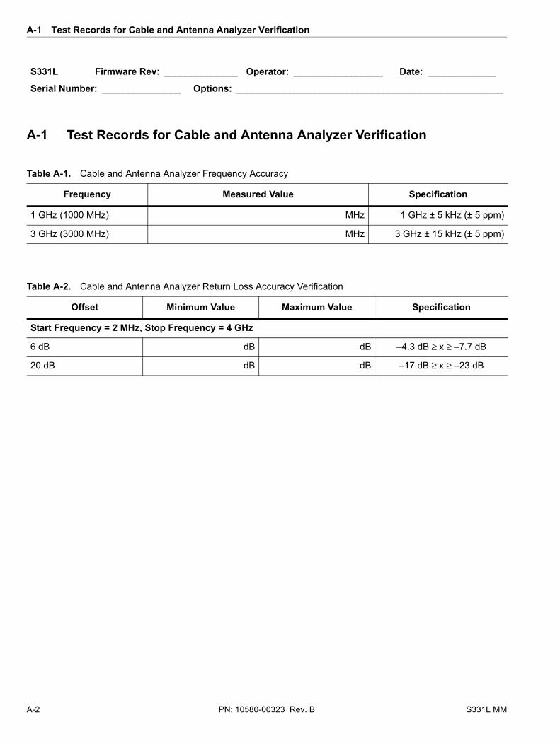
6. Record the frequency data in Table A-1, “Cable and Antenna Analyzer Frequency Accuracy” on page A-2.
7. Press the Freq/Dist menu key and set both the Start Freq and Stop Freq to 3 GHz.
8. Record the frequency data in Table A-1.
2-3 Return Loss Accuracy Verification S331L Performance Verification
2-2 PN: 10580-00323 Rev. B S331L MM
2-3 Return Loss Accuracy VerificationThe following test can be used to verify the accuracy of return loss measurements. Open/Short/Load calibration of the S331L in Cable and Antenna Analyzer mode is required for this test.
Equipment Required
• Open/Short Frequency: DC to 18 GHz Anritsu Model 22N50
• Precision Load: Anritsu Model SM/PL-1
• 6 dB Offset Termination Frequency: DC to 18.0 GHz Anritsu Model SC5905
• 20 dB Offset Termination Frequency: DC to 18.0 GHz Anritsu Model SC5906
Procedure
1. Verify that the S331L is in Cable and Antenna Analyzer mode and preset the unit.
2. Press the Measurement menu key, then press the Return Loss soft key.
3. Press the Calibration menu key.
4. Press the Start Calibration soft key. Follow the instructions on the screen using an OSL Cal Method and the Standard Cal Type to perform a calibration.
5. After the calibration is complete, install the 6 dB offset termination.
6. Press the AutoScl (.) key to adjust the display for the current trace.
7. Record the min and max values in Table A-2, “Cable and Antenna Analyzer Return Loss Accuracy Verification” on page A-2.
8. Remove the 6 dB offset and install the 20 dB offset.
9. Press the AutoScl (.) key to adjust the display for the current trace.
10. Record the min and max values in Table A-2.
S331L Performance Verification 2-4 Power Meter Verification
S331L MM PN: 10580-00323 Rev. B 2-3
2-4 Power Meter VerificationThe following test can be used to verify the accuracy of the Power Meter.
Equipment required
• Power Meter: Anritsu Model ML2437A
• Power Sensor: Anritsu Model SC7400
• Synthensizer: Anritsu Model MG3692B
• Power Splitter: Aeroflex/Weinschel Model 1870A
• RF Coaxial Cable: Anritsu Model 15NN50-0.6B
Procedure
1. Connect the SC7400 power sensor to the ML2437A power meter and zero/cal the sensor.
2. Set the SC7400 cal factor to 100 MHz or the next frequency within Table A-3, “Power Meter Verification” on page A-3.
3. Put S331L into Power Meter Mode, choose Calibration and turn Zero On.
4. Press the Frequency key and set the Measurement Frequency to 100 MHz or the next frequency within Table A-3.
5. Connect the MG3692B, SC7400 and S331L to the power splitter as shown in Figure 2-1.
6. On the MG3692B, set the frequency to 100 MHz or the next frequency within Table A-3 and adjust the power level so the ML2437A shows 0.0 dBm.
7. Record the S331L’s power reading in Table A-3.
Figure 2-1. Power Meter Measurement Accuracy
S331L Site Master
MG3692x Synthesized Signal Generator
ML2437A Power Meter
SC7400Sensor
1870A Power Splitter
Adapter
Enter
Menu
S331AL
Save 7
System 8
Preset 9
ScrnShot 4
Trace 5
Limit 6
File 1
Touch 2
Sweep 3
Help 0
AutoScl . Run/Hold
+/-
ESC
SiteMaster
2-4 Power Meter Verification S331L Performance Verification
2-4 PN: 10580-00323 Rev. B S331L MM
8. Adjust the MG3692B’s power level so the ML2437A reads -30 dBm.
9. Record the S331L’s power reading in Table A-3.
10. Repeat Step 2 through Step 9 for the other frequencies within Table A-3.
2-5 InstaCal VerificationThe following test can be used to verify the accuracy of return loss measurements using the InstaCal module to perform an OSL calibration on the S331L.
Equipment Required
• 6 dB Offset Termination Frequency: DC to 18.0 GHz Anritsu Model SC5905
• 20 dB Offset Termination Frequency: DC to 18.0 GHz Anritsu Model SC5906
Procedure
1. Verify that the S331L is in Cable and Antenna Analyzer mode and preset the unit.
2. Press the Measurement menu key, then press the Return Loss soft key.
3. Press the Calibration menu key.
4. Press the Start Calibration soft key. Follow the instructions on the screen using an InstaCal Cal Method and the Standard Cal Type to perform a calibration.
5. After the calibration is complete, remove the cable from the InstaCal port and install the 6 dB offset termination to the end of the cable.
6. Press the AutoScl (.) key to adjust the display for the current trace.
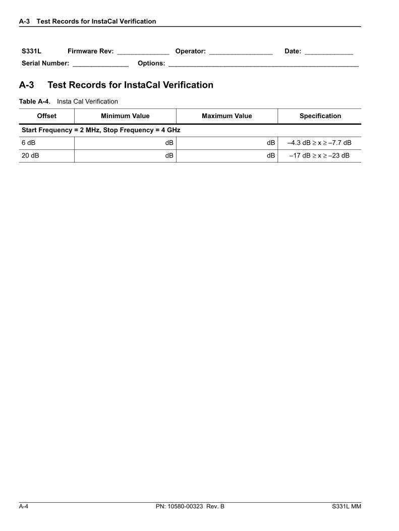
7. Record the min and max values in Table A-4, “Insta Cal Verification” on page A-4.
8. Remove the 6 dB offset and install the 20 dB offset.
9. Press the AutoScl (.) key to adjust the display for the current trace.
3-1 General InformationThe following information relates to the care and handling of the Anritsu PN ND74886 Lithium-Ion battery pack. The S331L has two separate batteries that should be replaced as a pair. The ND74886 includes two batteries. For information on removing and replacing the S331L batteries, see Section 4-1 “Replacing the S331L Batteries” on page 4-1
• The batteries supplied with the S331L may need charging before use. Before using the Site Master, charge the internal batteries using the AC-DC Adapter PN 40-187-R.
• Use only Anritsu approved battery packs.
• Recharge the battery only in the S331L, do not attempt to charge in an external charger.
• When the S331L is not in use, and the battery is fully charged, disconnect it from the power source.
• Do not charge batteries for longer than 24 hours; overcharging may shorten battery life.
• If left unused a fully charged battery will discharge itself over time.
• Temperature extremes affect the ability of the battery to charge: allow the battery to cool down or warm up as necessary before use or charging.
• Discharge the battery from time to time to improve battery performance and battery life.
• The battery can be charged and discharged hundreds of times, but it will eventually wear out.
• The battery may need to be replaced when the operating time between charging becomes noticeably shorter than normal.
• Never use a damaged or worn out battery.
• Storing the battery in extreme hot or cold places will reduce the capacity and lifetime of the battery.
• Never short-circuit the battery terminals.
• Do not drop, mutilate or attempt to disassemble the battery.
• Do not dispose of batteries in a fire!
• Batteries must be recycled or disposed of properly. Do not place batteries in household garbage.
• Always use the battery for its intended purpose only.
3-1 General Information Battery Information
3-2 PN: 10580-00323 Rev. B S331L MM
S331L MM PN: 10580-00323 Rev. B 4-1
Chapter 4 — Assembly Replacement
This section will provide a list of tools and procedures to replace the sub-assemblies within the S331L.
Tools Required:
• #1 Philips Screw Driver
• #6 Torx Screw Driver
• 19mm wrench
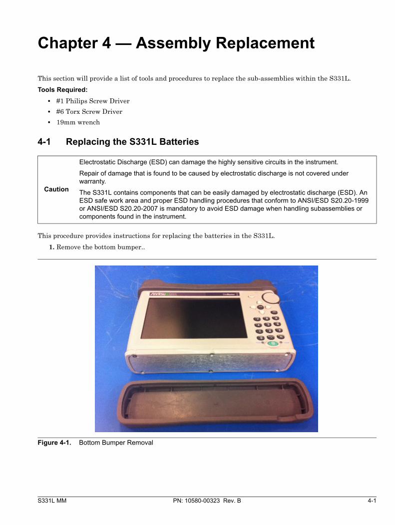
4-1 Replacing the S331L Batteries
This procedure provides instructions for replacing the batteries in the S331L.
1. Remove the bottom bumper..
Caution
Electrostatic Discharge (ESD) can damage the highly sensitive circuits in the instrument.
Repair of damage that is found to be caused by electrostatic discharge is not covered under warranty.
The S331L contains components that can be easily damaged by electrostatic discharge (ESD). An ESD safe work area and proper ESD handling procedures that conform to ANSI/ESD S20.20-1999 or ANSI/ESD S20.20-2007 is mandatory to avoid ESD damage when handling subassemblies or components found in the instrument.
Figure 4-1. Bottom Bumper Removal
4-1 Replacing the S331L Batteries Assembly Replacement
4-2 PN: 10580-00323 Rev. B S331L MM
2. Remove the six screws screws from the bottom of the unit holding the battery cover in place, and remove the battery cover.
3. Remove the battery connectors from the Main board by gently pulling on them and then remove the batteries from the unit..
4. Inserting batteries is the reverse of removing them.
Figure 4-2. Battery Cover Removed
Figure 4-3. Unplug the Battery Connectors and Remove the Batteries
Assembly Replacement 4-2 Removing the Rear Case to Gain Access to Internal Assemblies
S331L MM PN: 10580-00323 Rev. B 4-3
4-2 Removing the Rear Case to Gain Access to Internal Assemblies1. Remove the batteries as described in Section 4-1 “Replacing the S331L Batteries”
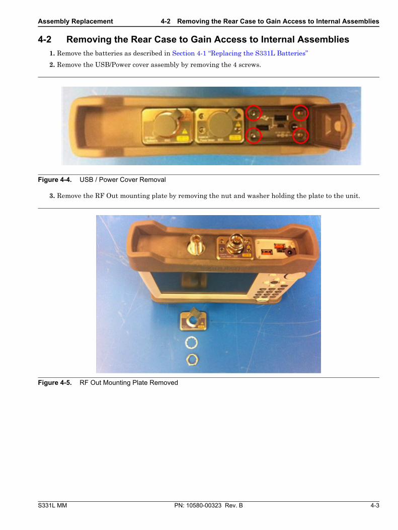
2. Remove the USB/Power cover assembly by removing the 4 screws.
3. Remove the RF Out mounting plate by removing the nut and washer holding the plate to the unit.
Figure 4-4. USB / Power Cover Removal
Figure 4-5. RF Out Mounting Plate Removed
4-2 Removing the Rear Case to Gain Access to Internal Assemblies Assembly Replacement
4-4 PN: 10580-00323 Rev. B S331L MM
4. Remove the InstaCal/PM module by removing the four screws holding the module in place and then gently pulling the module out.
5. Remove the top bumper, so now both bumpers, batteries, battery cover, RF Out top plate and the InstaCal/PM module are all removed..
Figure 4-6. Remove 4 screws and InstaCal / PM Module
Figure 4-7. Both Bumpers, Batteries, Battery Cover, RF Out Mounting Plate and InstaCal/PM Module Removed
Assembly Replacement 4-2 Removing the Rear Case to Gain Access to Internal Assemblies
S331L MM PN: 10580-00323 Rev. B 4-5
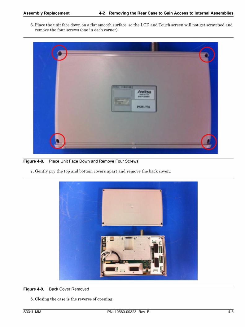
6. Place the unit face down on a flat smooth surface, so the LCD and Touch screen will not get scratched and remove the four screws (one in each corner).
7. Gently pry the top and bottom covers apart and remove the back cover..
8. Closing the case is the reverse of opening.
Figure 4-8. Place Unit Face Down and Remove Four Screws
This section describes the removal and replacement of the Main/VNA PCB which is attached to the S331L Case.
1. Remove the batteries as described in Section 4-1 “Replacing the S331L Batteries” on page 4-1
2. Remove the rear case as described in Section 4-2 “Removing the Rear Case to Gain Access to Internal Assemblies” on page 4-3.
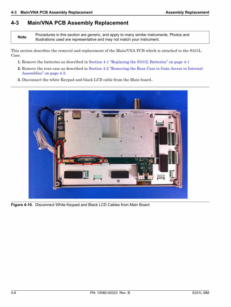
3. Disconnect the white Keypad and black LCD cable from the Main board..
NoteProcedures in this section are generic, and apply to many similar instruments. Photos and illustrations used are representative and may not match your instrument.
Figure 4-10. Disconnect White Keypad and Black LCD Cables from Main Board
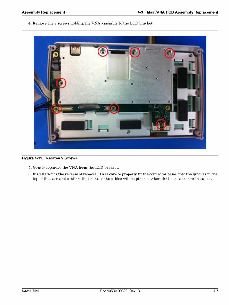
4. Remove the 7 screws holding the VNA assembly to the LCD bracket.
5. Gently separate the VNA from the LCD bracket.
6. Installation is the reverse of removal. Take care to properly fit the connector panel into the grooves in the top of the case and confirm that none of the cables will be pinched when the back case is re-installed.
Figure 4-11. Remove 9 Screws
4-4 InstaCal / Power Meter Assembly Replacement Assembly Replacement
4-8 PN: 10580-00323 Rev. B S331L MM
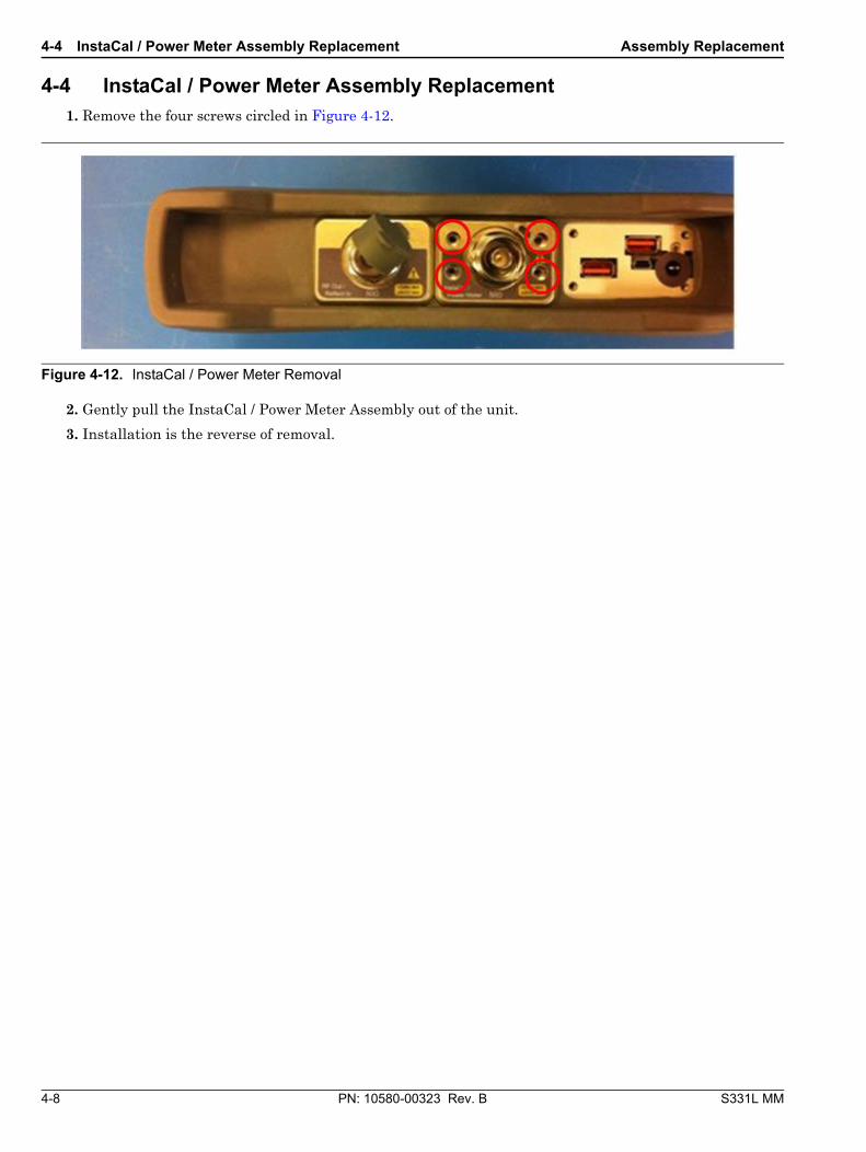
4-4 InstaCal / Power Meter Assembly Replacement1. Remove the four screws circled in Figure 4-12.
2. Gently pull the InstaCal / Power Meter Assembly out of the unit.
3. Installation is the reverse of removal.
Figure 4-12. InstaCal / Power Meter Removal
Assembly Replacement 4-5 LCD and Touch Screen Assembly Replacement
S331L MM PN: 10580-00323 Rev. B 4-9
4-5 LCD and Touch Screen Assembly ReplacementThis procedure provides instructions for removing and replacing the Liquid Crystal Display (LCD) and touch screen assembly.
1. Remove the batteries as described in Section 4-1 “Replacing the S331L Batteries” on page 4-1.
2. Remove the rear case as described in Section 4-2 “Removing the Rear Case to Gain Access to Internal Assemblies” on page 4-3.
3. Remove the VNA Assembly as described in Section 4-3 “Main/VNA PCB Assembly Replacement” on page 4-6
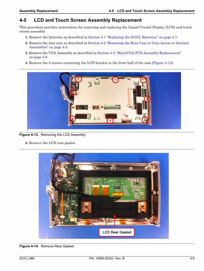
4. Remove the 8 screws connecting the LCD bracket to the front half of the case (Figure 4-13).
5. Remove the LCD rear gasket.
Figure 4-13. Removing the LCD Assembly
Figure 4-14. Remove Rear Gasket
4-5 LCD and Touch Screen Assembly Replacement Assembly Replacement
4-10 PN: 10580-00323 Rev. B S331L MM
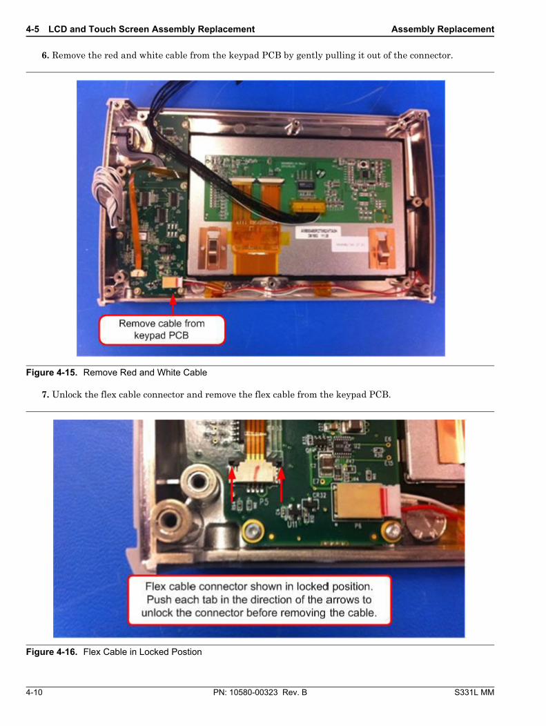
6. Remove the red and white cable from the keypad PCB by gently pulling it out of the connector.
7. Unlock the flex cable connector and remove the flex cable from the keypad PCB.
Figure 4-15. Remove Red and White Cable
Figure 4-16. Flex Cable in Locked Postion
Assembly Replacement 4-5 LCD and Touch Screen Assembly Replacement
S331L MM PN: 10580-00323 Rev. B 4-11
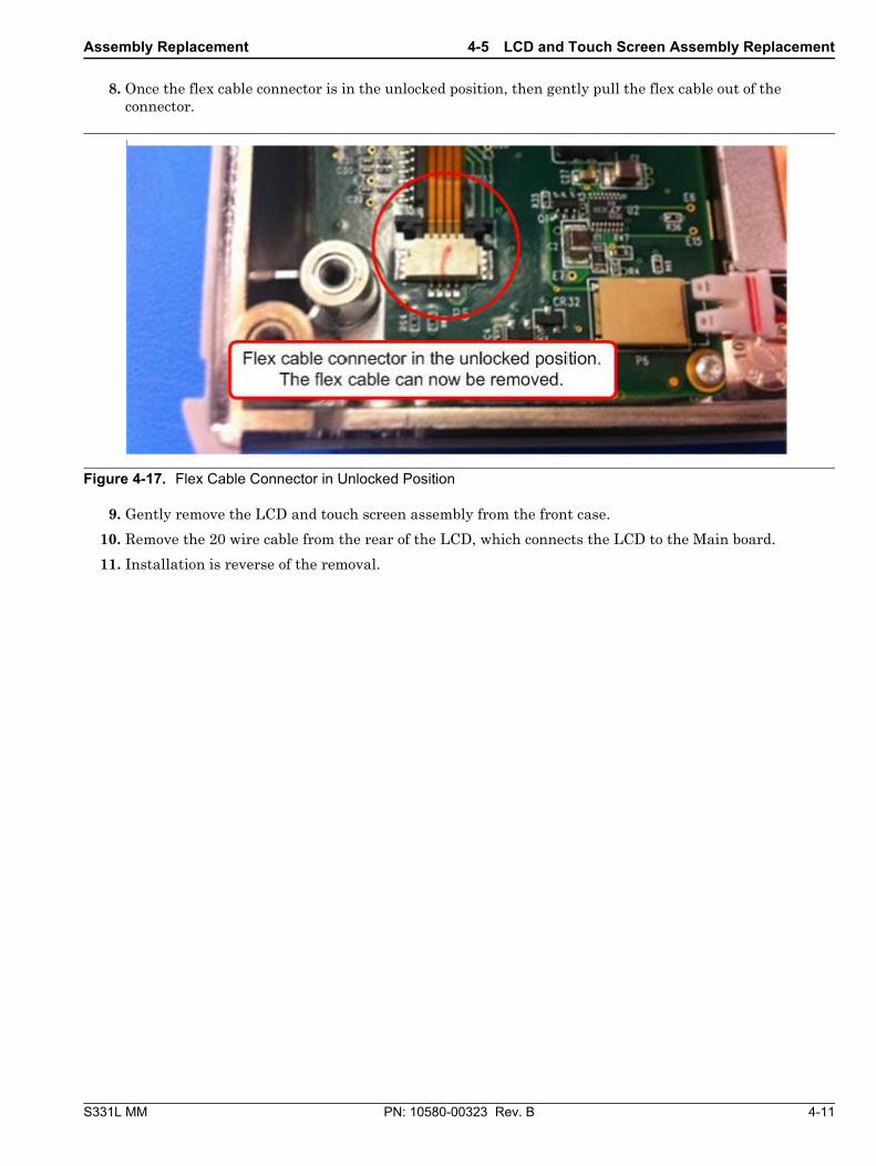
8. Once the flex cable connector is in the unlocked position, then gently pull the flex cable out of the connector.
9. Gently remove the LCD and touch screen assembly from the front case.
10. Remove the 20 wire cable from the rear of the LCD, which connects the LCD to the Main board.
11. Installation is reverse of the removal.
Figure 4-17. Flex Cable Connector in Unlocked Position
4-6 Keypad PCB and Rubber Keypad Replacement Assembly Replacement
4-12 PN: 10580-00323 Rev. B S331L MM
4-6 Keypad PCB and Rubber Keypad Replacement1. Remove the batteries as described in Section 4-1 “Replacing the S331L Batteries” on page 4-1.
2. Remove the rear case as described in Section 4-2 “Removing the Rear Case to Gain Access to Internal Assemblies” on page 4-3.
3. Remove the VNA Assembly as described in Section 4-3 “Main/VNA PCB Assembly Replacement” on page 4-6
4. Remove the LCD and Touch Screen Assembly as described in Section 4-5 “LCD and Touch Screen Assembly Replacement” on page 4-9
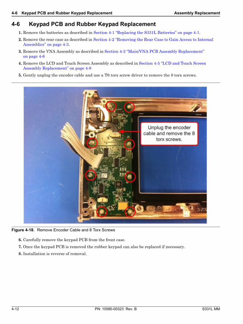
5. Gently unplug the encoder cable and use a T6 torx screw driver to remove the 8 torx screws.
6. Carefully remove the keypad PCB from the front case.
7. Once the keypad PCB is removed the rubber keypad can also be replaced if necessary.
8. Installation is reverse of removal.
Figure 4-18. Remove Encoder Cable and 8 Torx Screws
Assembly Replacement 4-7 SOM Module Replacement
S331L MM PN: 10580-00323 Rev. B 4-13
4-7 SOM Module Replacement This procedure provides instructions for removing and replacing the SOM module attached to the Main/VNA PCB.
1. Remove the batteries as described in Section 4-1 “Replacing the S331L Batteries” on page 4-1.
2. Remove the Rear Case as described in Section 4-2 “Removing the Rear Case to Gain Access to Internal Assemblies” on page 4-3
3. Remove the Main/VNA PCB assembly from the front panel as described in Section 4-3 “Main/VNA PCB Assembly Replacement” on page 4-6.
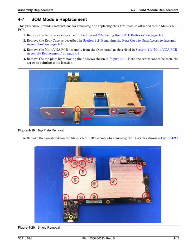
4. Remove the top plate by removing the 6 screws shown in Figure 4-19. Note one screw cannot be seen, the arrow is pointing to its location.
5. Remove the two shields on the Main/VNA PCB assembly by removing the 14 screws shown inFigure 4-20.
Figure 4-19. Top Plate Removal
Figure 4-20. Shield Removal
4-7 SOM Module Replacement Assembly Replacement
4-14 PN: 10580-00323 Rev. B S331L MM
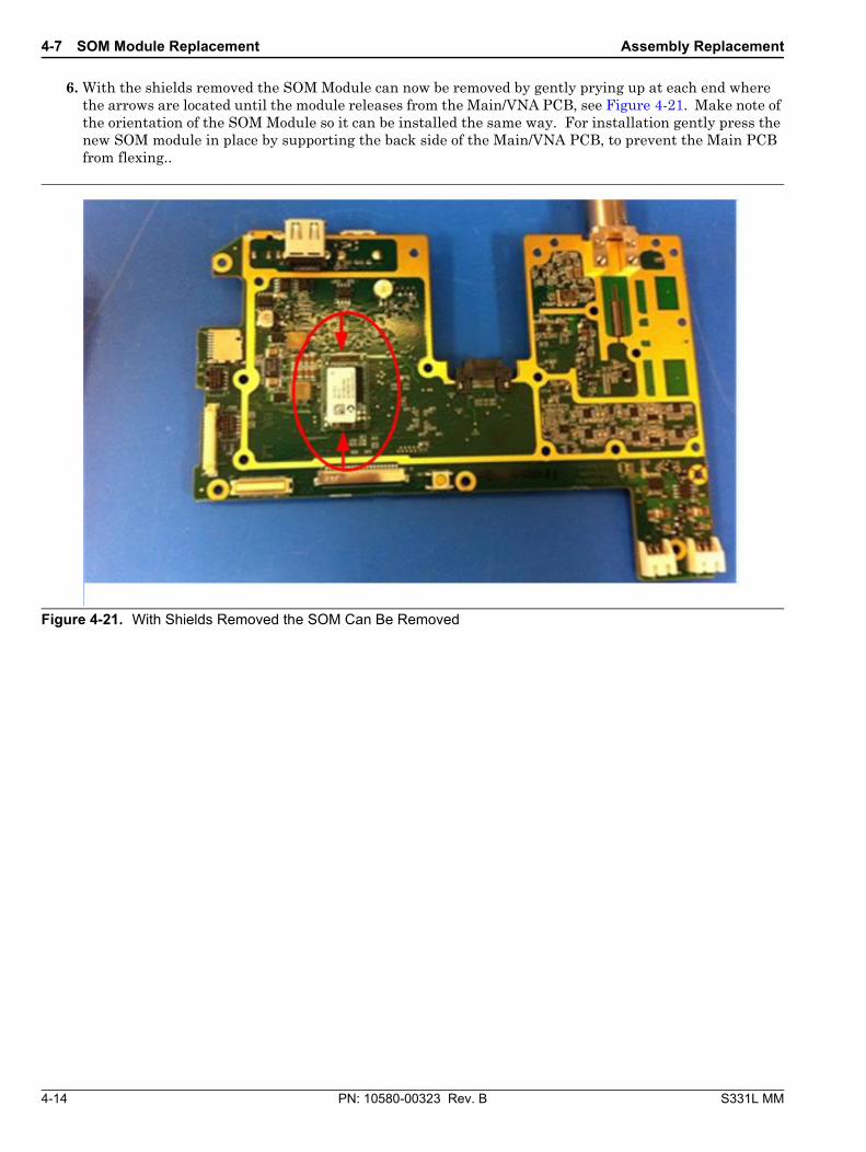
6. With the shields removed the SOM Module can now be removed by gently prying up at each end where the arrows are located until the module releases from the Main/VNA PCB, see Figure 4-21. Make note of the orientation of the SOM Module so it can be installed the same way. For installation gently press the new SOM module in place by supporting the back side of the Main/VNA PCB, to prevent the Main PCB from flexing..
Figure 4-21. With Shields Removed the SOM Can Be Removed
Assembly Replacement 4-7 SOM Module Replacement
S331L MM PN: 10580-00323 Rev. B 4-15
7. After the SOM module has been replaced, then Test Fixture T4011 is needed to re-install the two shields to the Main board.
Figure 4-22. Test Fixture T4011 with Lever in Up Position
4-7 SOM Module Replacement Assembly Replacement
4-16 PN: 10580-00323 Rev. B S331L MM
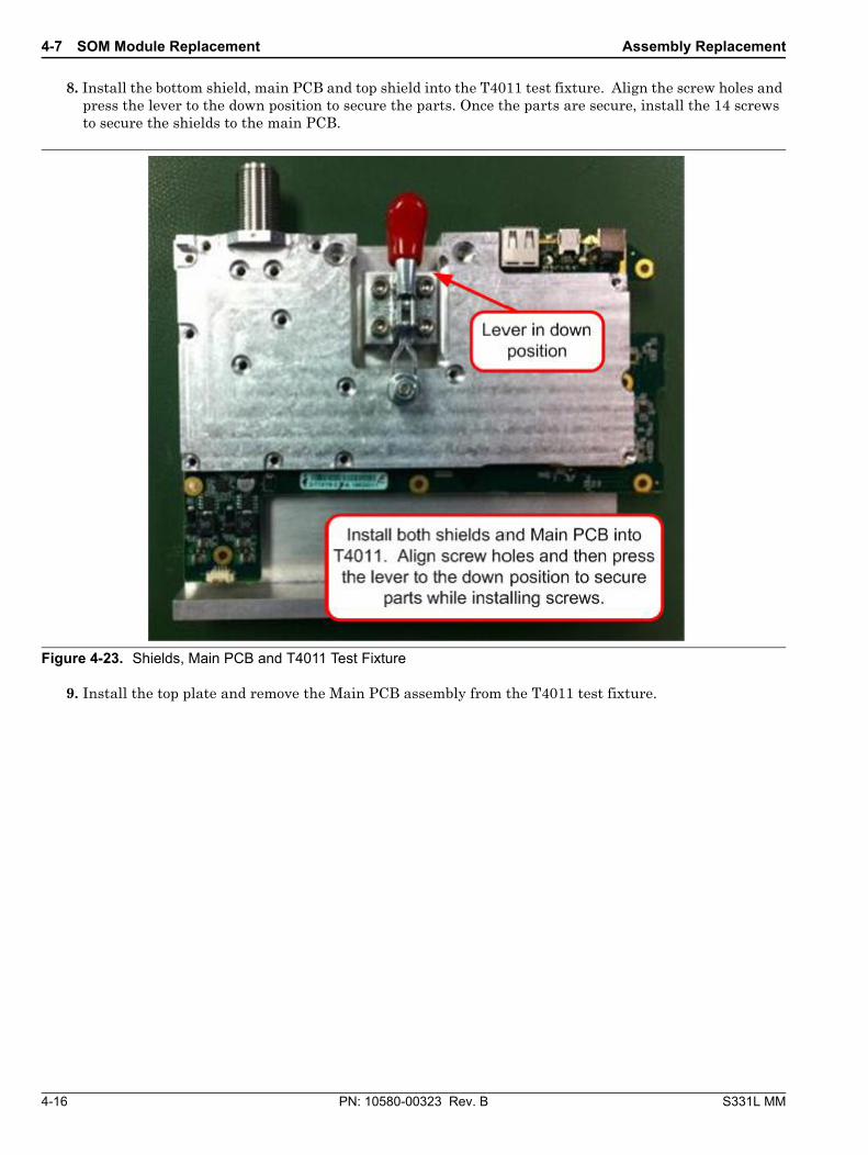
8. Install the bottom shield, main PCB and top shield into the T4011 test fixture. Align the screw holes and press the lever to the down position to secure the parts. Once the parts are secure, install the 14 screws to secure the shields to the main PCB.
9. Install the top plate and remove the Main PCB assembly from the T4011 test fixture.
Figure 4-23. Shields, Main PCB and T4011 Test Fixture
S331L MM PN: 10580-00323 Rev. B 5-1
Chapter 5 — Troubleshooting
5-1 IntroductionThis chapter describes the primary troubleshooting operations that can be performed by all Anritsu Service Centers. Perform the troubleshooting suggestions in the order they are listed. Operators of the S331L should refer to the User Guide for troubleshooting help.
Only qualified Anritsu personnel should replace internal assemblies. Major subassemblies shown in Table 1-2, “List of Replaceable Parts” on page 1-3 are typically the items that may be replaced. Because they are highly fragile, items that must be soldered may not be replaced without special training. Removal of RF shields from PC boards or adjustment of screws on or near the shields will detune sensitive RF circuits and will result in degraded instrument performance.
Turn-on Problems
Unit cannot boot-up, no activity occurs when the On/Off key is pressed:
1. Batteries may be fully discharged. Confirm the batteries are installed into the unit and connect the AC to DC converter (Anritsu part number 40-187-R) to the unit allowing the batteries to charge.
2. Battery may be the wrong type. Use only Anritsu approved battery packs. Some non-approved battery packs will fit into the S331L, but are electrically incompatible and will not charge correctly.
3. External power supply may have failed or be the wrong type. Replace the external power supply.
4. On/Off switch is damaged. Replace the keypad PCB or rubber keypad.
5. Main PCB has failed. Replace the Main PCB including the SOM assembly.
Unit begins the boot process, but does not complete boot-up:
1. SOM has failed. Replace the SOM assembly.
2. Main PCB has failed. Replace the Main PCB including the SOM assembly.
Unit makes normal boot-up sounds, but the display has a problem:
1. If the display is dim, check the Brightness setting under the System, Display/Audio Menu.
2. Verify the cable between the LCD and Main PCB is properly seated.
3. Replace the LCD and touch screen assembly.
4. The Main PCB has failed. Replace the Main PCB including the SOM assembly.
Boot-up Self Test fails:
1. Perform a Master Reset.
2. The Main PCB has failed. Replace the Main PCB including the SOM assembly.
5-1 Introduction Troubleshooting
5-2 PN: 10580-00323 Rev. B S331L MM
Other Problems
Battery Pack Charging Problems: refer to Chapter 3, “Battery Information”.
Power Meter, Problems:
1. If measured power is slightly out of specification, verify the measurement frequency is set to the same frequency as the power being measured.
2. Replace the InstaCal / Power Meter Module.
Cable and Antenna Analyzer Problems:
1. Inspect the RFout connector for damage.
2. Inspect the Open, Short, Load and cable(s) for damage. Verify their operation on a suitable measurement instrument.
3. Compare an OSL calibration to an InstaCal calibration using 6 and 20 dB offsets to see if the calibration is causing the fault.
4. Refer to the User Guide.
5. VNA module has failed. Replace the Main PCB.
Touch Screen does not react:
1. Verify the flex cable between the touch screen and keypad PCB and ensure it is properly seated into the connector on the keypad PCB and the connector is locked.
2. Replace the touch screen / LCD assembly.
3. Replaced the keypad PCB.
Hard Keys do not react:
1. Verify the cable connecting the keypad PCB to the Main PCB is properly seated at both ends and the cable is not damaged.
2. Verify there is no debris between the rubber keypad and keypad PCB.
3. Replace the keypad PCB.
4. Replace the rubber keypad.
S331L MM PN: 10580-00323 Rev. B A-1
Appendix A — Test RecordsThis appendix provides test records that can be used to record the performance of the S331L. Anritsu recommends that you make a copy of the following test record pages and document the measurements each time a Performance Verification is performed. Continuing to document this process each time it is performed provides a detailed history of instrument performance, which can allow you to observe trends.
A-1 Test Records for Cable and Antenna Analyzer Verification
A-2 PN: 10580-00323 Rev. B S331L MM
A-1 Test Records for Cable and Antenna Analyzer Verification