Corporate Headquarters Cisco Systems, Inc. 170 West Tasman Drive San Jose, CA 95134-1706 USA http://www.cisco.com Tel: 408 526-4000 800 553-NETS (6387) Fax: 408 526-4100 Site Survey Guide for Deploying Cisco 7920 IP Phones April 2005 Text Part Number: OL-6315-01
Transcript
Site Survey Guide for Deploying Cisco 7920 IP PhonesApril 2005
Corporate HeadquartersCisco Systems, Inc.170 West Tasman DriveSan Jose, CA 95134-1706 USAhttp://www.cisco.comTel: 408 526-4000
THE SPECIFICATIONS AND INFORMATION REGARDING THE PRODUCTS IN THIS MANUAL ARE SUBJECT TO CHANGE WITHOUT NOTICE. ALL STATEMENTS, INFORMATION, AND RECOMMENDATIONS IN THIS MANUAL ARE BELIEVED TO BE ACCURATE BUT ARE PRESENTED WITHOUT WARRANTY OF ANY KIND, EXPRESS OR IMPLIED. USERS MUST TAKE FULL RESPONSIBILITY FOR THEIR APPLICATION OF ANY PRODUCTS.
THE SOFTWARE LICENSE AND LIMITED WARRANTY FOR THE ACCOMPANYING PRODUCT ARE SET FORTH IN THE INFORMATION PACKET THAT SHIPPED WITH THE PRODUCT AND ARE INCORPORATED HEREIN BY THIS REFERENCE. IF YOU ARE UNABLE TO LOCATE THE SOFTWARE LICENSE OR LIMITED WARRANTY, CONTACT YOUR CISCO REPRESENTATIVE FOR A COPY.
The following information is for FCC compliance of Class A devices: This equipment has been tested and found to comply with the limits for a Class A digital device, pursuant to part 15 of the FCC rules. These limits are designed to provide reasonable protection against harmful interference when the equipment is operated in a commercial environment. This equipment generates, uses, and can radiate radio-frequency energy and, if not installed and used in accordance with the instruction manual, may cause harmful interference to radio communications. Operation of this equipment in a residential area is likely to cause harmful interference, in which case users will be required to correct the interference at their own expense.
The following information is for FCC compliance of Class B devices: The equipment described in this manual generates and may radiate radio-frequency energy. If it is not installed in accordance with Cisco’s installation instructions, it may cause interference with radio and television reception. This equipment has been tested and found to comply with the limits for a Class B digital device in accordance with the specifications in part 15 of the FCC rules. These specifications are designed to provide reasonable protection against such interference in a residential installation. However, there is no guarantee that interference will not occur in a particular installation.
Modifying the equipment without Cisco’s written authorization may result in the equipment no longer complying with FCC requirements for Class A or Class B digital devices. In that event, your right to use the equipment may be limited by FCC regulations, and you may be required to correct any interference to radio or television communications at your own expense.
You can determine whether your equipment is causing interference by turning it off. If the interference stops, it was probably caused by the Cisco equipment or one of its peripheral devices. If the equipment causes interference to radio or television reception, try to correct the interference by using one or more of the following measures:
• Turn the television or radio antenna until the interference stops.
• Move the equipment to one side or the other of the television or radio.
• Move the equipment farther away from the television or radio.
• Plug the equipment into an outlet that is on a different circuit from the television or radio. (That is, make certain the equipment and the television or radio are on circuits controlled by different circuit breakers or fuses.)
Modifications to this product not authorized by Cisco Systems, Inc. could void the FCC approval and negate your authority to operate the product.
NOTWITHSTANDING ANY OTHER WARRANTY HEREIN, ALL DOCUMENT FILES AND SOFTWARE OF THESE SUPPLIERS ARE PROVIDED “AS IS” WITH ALL FAULTS. CISCO AND THE ABOVE-NAMED SUPPLIERS DISCLAIM ALL WARRANTIES, EXPRESSED OR IMPLIED, INCLUDING, WITHOUT LIMITATION, THOSE OF MERCHANTABILITY, FITNESS FOR A PARTICULAR PURPOSE AND NONINFRINGEMENT OR ARISING FROM A COURSE OF DEALING, USAGE, OR TRADE PRACTICE.
IN NO EVENT SHALL CISCO OR ITS SUPPLIERS BE LIABLE FOR ANY INDIRECT, SPECIAL, CONSEQUENTIAL, OR INCIDENTAL DAMAGES, INCLUDING, WITHOUT LIMITATION, LOST PROFITS OR LOSS OR DAMAGE TO DATA ARISING OUT OF THE USE OR INABILITY TO USE THIS MANUAL, EVEN IF CISCO OR ITS SUPPLIERS HAVE BEEN ADVISED OF THE POSSIBILITY OF SUCH DAMAGES.
CCSP, CCVP, the Cisco Square Bridge logo, Follow Me Browsing, and StackWise are trademarks of Cisco Systems, Inc.; Changing the Way We Work, Live, Play, and Learn, and iQuick Study are service marks of Cisco Systems, Inc.; and Access Registrar, Aironet, ASIST, BPX, Catalyst, CCDA, CCDP, CCIE, CCIP, CCNA, CCNP, Cisco, the Cisco Certified Internetwork Expert logo, Cisco IOS, Cisco Press, Cisco Systems, Cisco Systems Capital, the Cisco Systems logo, Cisco Unity, Empowering the Internet Generation, Enterprise/Solver, EtherChannel, EtherFast, EtherSwitch, Fast Step, FormShare, GigaDrive, GigaStack, HomeLink, Internet Quotient, IOS, IP/TV, iQ Expertise, the iQ logo, iQ Net Readiness Scorecard, LightStream, Linksys, MeetingPlace, MGX, the Networkers logo, Networking Academy, Network Registrar, Packet, PIX, Post-Routing, Pre-Routing, ProConnect, RateMUX, ScriptShare, SlideCast, SMARTnet, StrataView Plus, TeleRouter, The Fastest Way to Increase Your Internet Quotient, and TransPath are registered trademarks of Cisco Systems, Inc. and/or its affiliates in the United States and certain other countries.
All other trademarks mentioned in this document or Website are the property of their respective owners. The use of the word partner does not imply a partnership relationship between Cisco and any other company. (0502R)
OL-6315-01
C O N T E N T S
Preface v
C H A P T E R 1 Overview 1-1
Recommendations for Successful VoIP Surveys 1-1
Getting started 1-2
Minimum Requirements for WIPT Cells 1-4
The Ideal WIPT Environment 1-5
Data Rate and Signal Strength Considerations 1-6
Multi-floor survey 1-7
Comparison of a Manual Survey and an Automated Survey 1-8
C H A P T E R 2 Survey Tools 2-1
Survey Tools for Packet Jitter 2-11
C H A P T E R 3 Surveying for Cell Capacity and Channel Re-Use 3-1
Survey Design for Cell Capacity 3-1
C H A P T E R 4 Conducting a WIPT Survey 3
How To Survey for the WIPT 3
Channel Re-Use 4
Manual Survey for the WIPT 5
Automated Survey for the WIPT 6
C H A P T E R 5 Positioning Access Points and Antennas for Site Surveys 4-1
Access Point Positioning 4-1
Antennas and Antenna Positioning 4-2
A P P E N D I X A Additional Sources of Information A-1
iiiSite Survey Guide for Deploying Cisco 7920 IP Phones
Contents
ivSite Survey Guide for Deploying Cisco 7920 IP Phones
OL-6315-01
Preface
This document provides instructions and guidelines for conducting a site survey for wireless LANs using Voice over IP (VoIP) on Cisco 7920 IP Phones.
With the introduction of voice to a predominantly wireless data network the methodology of site surveys will have to be altered. Voice over WLAN is a new application to wireless technology. Many of the survey techniques used for WLAN must be updated.
This document is intended to identify many of the recommended techniques and tools needed to successfully deploy VoIP over an 802.11 wireless network. The recommendations made in this document supersede all other guides on doing site surveys. However, other site survey guides or training documents are valuable and a necessary prerequisite to this recommendation guide.
Surveying for wireless voice coverage requires more effort and time than for data-only coverage at the same site. A voice survey requires planning of coverage plus the planning of capacity. Wireless data is less susceptible to disruption than wireless voice when it comes to cell overlap, RF noise, and packet delay.
vSite Survey Guide for Deploying Cisco 7920 IP Phones
OL-6315-01
Preface
viSite Survey Guide for Deploying Cisco 7920 IP Phones
OL-6315-01
Site Survey GuOL-6315-01
C H A P T E R 1
Overview
This document begins by identifying the specific radio environmental values that are needed for a successful voice deployment.
Note Cisco offers a Cisco Aironet Wireless Site Survey class for technical individuals who will be performing site surveys for wireless LAN solutions. This white paper does not replace the information in the site survey class. Cisco recommends that wireless LAN survey technicians take the Aironet Wireless Site Survey class as a requisite. Cisco also recommends that technicians study the Cisco Wireless IP Phone 7920 Deployment Recommendations before studying this white paper.
There are two types of wireless LAN VoIP surveys:
• A survey performed with Wireless IP Telephony (WIPT) handsets
• A survey that simulates WIPT operation
Cisco recommends that, if possible, you install the VoIP network following AVVID design guidelines before surveying for a WIPT network.
Tip Click this link to browse to a library of AVVID design guides:http://www.cisco.com/warp/public/779/largeent/it/ese/srnd.html
Recommendations for Successful VoIP SurveysThe most effective surveys are performed using Cisco access points and Cisco WIPT handsets on active calls through Cisco’s Call Manager. In the site survey, it is important that you test performance from the source to the end point and also from the end point to the source. For example, your WIPT site survey should use a wired VoIP phone (such as a Cisco 7960) in the core of the network to a WIPT (such as a Cisco 7920) handset with a live conversation going in both directions. The Cisco 7920 WIPT handset enables you to audibly monitor the quality of the call. Cisco also recommends that you use the customer’s actual handset configuration when performing the survey.
Cisco considers it necessary to re-survey for voice at a site that has a trouble-free WLAN data network. Voice traffic is isochronous—to be usable, it must be transmitted without delay. Voice traffic has strict resource requirements for guaranteed bandwidth, low latency, low jitter, and low packet loss. The 7920 G.711 codec voice packets require a guaranteed bandwidth of 80 kbps. The G.711 packets have a 160-byte payload plus a 40-byte RTP/UDP/IP protocol overhead. Typically, voice packets are sent every 20 milliseconds (ms), and a corresponding service rate is expected from the network by the voice application. A delay or loss of two or more contiguous voice packets is generally noticeable as quality
Chapter 1 OverviewRecommendations for Successful VoIP Surveys
degradation. This quality requirement also dictates the need for a fast roaming solution between access points where the network can reassociate a client to a new access point within 100 ms (that is, without suffering at most one packet delay or loss). People often walk around while talking on the phone, so users making voice calls tend to roam more than users of wireless computers. Users of wireless computers roam, but because very few users walk and use their computers at the same time, computer users are not using their computers when the roam occurs.
Because it might not be possible to have a VoIP network and WLAN network in place before the WIPT site survey, this document also describes a WIPT site survey process using standard wireless client cards and utilities.
Cisco recommends that all WIPT site surveys use diversity enabled access points and diversity antennas because a diversity configuration provides better throughput performance. A simple throughput test using an FTP data transfer of 50 MB in an office environment (with low multi-path signals) shows a 3-second improvement when using a diversity configuration. Diversity configurations are especially important in environments such as shop floors and hospitals, which often have heavy multi-path signals.
Cisco also recommends that you use 256-byte packets when you perform receive and transmit tests during the survey. Voice traffic consists of two-way transmissions, usually a burst of packets in one direction followed by a burst of packets in the other direction. You should check performance, error rates, and signal levels in both directions.
This document also describes how to use signal levels and signal-to-noise ratios (SNRs) in WIPT site surveys. WLAN site surveys that use only signal level tests are designed to identify the wireless network coverage area. Previous site surveys have shown that signal level tests alone are not sufficient for voice traffic and many times are not sufficient for data traffic. WIPT site surveys must also consider voice call capacity within a wireless cell. Currently, call loading is 7 active voice calls per channel using the G711 codec. This number is based on simultaneous requirements for data clients and quality voice calls with current data rates and packet sizes. Cisco recommends that all WIPT site surveys and installations use non-overlapping channels. For 802.11b/g operation the non-overlapping channels are a minimum of 5 radio channels apart. Cisco also recommends that you use a data rate of 11 Mbps to determine the cell size for the Cisco 7920 WIPT handset. If other data rates are allowed, call capacity might be substantially lower.
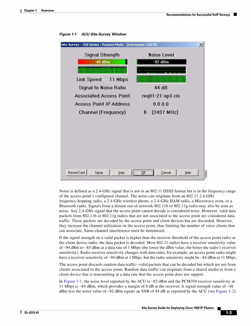
Getting started Part of any site survey is measuring the noise level within a wireless cell. Noise levels vary from site to site and also within different locations of a site. The noise level affects a radio’s ability to receive data or voice packets. Figure 1-1 uses the Cisco Aironet Client Utility (ACU) and a Cisco PCM350 client adapter to identify the noise level, signal strength, and SNR at a specific location with a wireless cell. The ACU window shows that the signal strength is –48 dBm, the noise level is –92 dBm, and the SNR is 44 dB.
1-2Site Survey Guide for Deploying Cisco 7920 IP Phones
OL-6315-01
Chapter 1 OverviewRecommendations for Successful VoIP Surveys
Figure 1-1 ACU Site Survey Window
Noise is defined as a 2.4-GHz signal that is not in an 802.11 DSSS format but is in the frequency range of the access point’s configured channel. The noise can originate from an 802.11 2.4-GHz frequency-hopping radio, a 2.4-GHz wireless phone, a 2.4-GHz HAM radio, a Microwave oven, or a Bluetooth radio. Signals from a distant out-of-network 802.11b or 802.11g radio may also be seen as noise. Any 2.4-GHz signal that the access point cannot decode is considered noise. However, valid data packets from 802.11b or 802.11g radios that are not associated to the access point are considered data traffic. Those packets are decoded by the access point and client devices but are discarded. However, they increase the channel utilization on the access point, thus limiting the number of voice clients that can associate. Same-channel interference must be minimized.
If the signal strength on a valid packet is higher than the receiver threshold of the access point radio or the client device radio, the data packet is decoded. Most 802.11 radios have a receiver sensitivity value of –94 dBm to –85 dBm at a data rate of 1 Mbps (the lower the dBm value, the better the radio’s receiver sensitivity). Radio receiver sensitivity changes with data rates; for example, an access point radio might have a receiver sensitivity of –94 dBm at 1 Mbps, but the radio sensitivity might be –84 dBm at 11 Mbps.
The access point discards random data traffic--valid packets that can be decoded but which are not from clients associated to the access point. Random data traffic can originate from a shared media or from a client device that is transmitting at a data rate that the access point does not support.
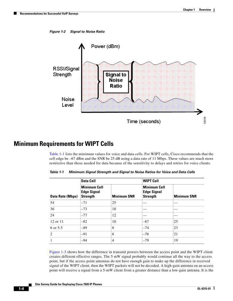
In Figure 1-1, the noise level reported by the ACU is –92 dBm and the PCM350 receiver sensitivity at 11 Mbps is –84 dBm, which provides a margin of 8 dB at the receiver. A signal strength value of –48 dBm less the noise value of –92 dBm equals an SNR of 44 dB as reported by the ACU (see Figure 1-2).
1-3Site Survey Guide for Deploying Cisco 7920 IP Phones
OL-6315-01
Chapter 1 OverviewRecommendations for Successful VoIP Surveys
Figure 1-2 Signal to Noise Ratio
Minimum Requirements for WIPT CellsTable 1-1 lists the minimum values for voice and data cells. For WIPT cells, Cisco recommends that the cell edge be –67 dBm and the SNR be 25 dB using a data rate of 11 Mbps. These values are much more restrictive than those needed for data because of the sensitivity to delays and retries for voice clients.
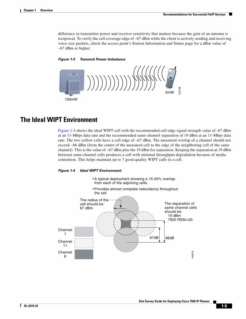
Figure 1-3 shows how the difference in transmit powers between the access point and the WIPT client creates different effective ranges. The 5 mW signal probably would continue all the way to the access point, but if the access point antennas do not have enough gain to make up the difference in received signal of the WIPT client, then the WIPT packets will not be decoded. A high-gain antenna on an access point will receive a signal from a 5-mW client from a greater distance than a low-gain antenna. It is the
Table 1-1 Minimum Signal Strength and Signal to Noise Ratios for Voice and Data Cells
Data Rate (Mbps)
Data Cell WIPT Cell
Minimum Cell Edge Signal Strength Minimum SNR
Minimum Cell Edge Signal Strength Minimum SNR
54 –71 25 — —
36 –73 18 — —
24 –77 12 — —
12 or 11 –82 10 –67 25
6 or 5.5 –89 8 –74 23
2 –91 6 –76 21
1 –94 4 –79 19
1-4Site Survey Guide for Deploying Cisco 7920 IP Phones
OL-6315-01
Chapter 1 OverviewRecommendations for Successful VoIP Surveys
difference in transmitter power and receiver sensitivity that matters because the gain of an antenna is reciprocal. To verify the cell coverage edge of –67 dBm while the client is actively sending and receiving voice size packets, check the access point’s Station Information and Status page for a dBm value of –67 dBm or higher.
Figure 1-3 Transmit Power Imbalance
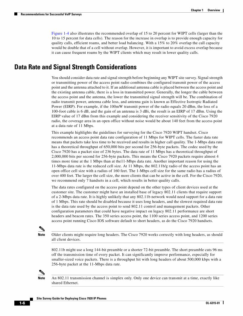
The Ideal WIPT EnvironmentFigure 1-4 shows the ideal WIPT cell with the recommended cell edge signal strength value of -67 dBm at an 11-Mbps data rate and the recommended same-channel separation of 19 dBm at an 11-Mbps data rate. The two yellow cells have a cell edge of –67 dBm. The measured overlap of a channel should not exceed –86 dBm (from the center of the measured cell to the edge of the neighboring cell of the same channel). This is the value of –67 dBm plus the 19 dBm for separation. Keeping the separation at 19 dBm between same-channel cells produces a cell with minimal throughput degradation because of media contention. This helps maintain up to 7 good-quality WIPT calls in a cell.
Figure 1-4 Ideal WIPT Environment
100mW
5mW
13
51
08
A typical deployment showing a 15-20% overlapfrom each of the adjoining cells.
Provides almost complete redundancy throughoutthe cell
The radius of thecell should be:67 dBm
The separation ofsame channel cellsshould be: 19 dBm 7920 RSSI=20
67dB 86dB
1350
75
Channel1
Channel11
Channel6
1-5Site Survey Guide for Deploying Cisco 7920 IP Phones
OL-6315-01
Chapter 1 OverviewRecommendations for Successful VoIP Surveys
Figure 1-4 also illustrates the recommended overlap of 15 to 20 percent for WIPT cells (larger than the 10 to 15 percent for data cells). The reason for the increase in overlap is to provide enough capacity for quality calls, efficient roams, and better load balancing. With a 15% to 20% overlap the call capacity would be double that of a cell without overlap. However, it is important to avoid excess overlap because it can cause frequent roams by the WIPT clients which may result in lower quality calls.
Data Rate and Signal Strength ConsiderationsYou should consider data rate and signal strength before beginning any WIPT site survey. Signal strength or transmitting power of the access point radio combines the configured transmit power of the access point and the antenna attached to it. If an additional antenna cable is placed between the access point and the existing antenna cable, there is a loss in transmitted power. Generally, the longer the cable between the access point and the antenna, the lower the transmitted signal strength will be. The combination of radio transmit power, antenna cable loss, and antenna gain is known as Effective Isotropic Radiated Power (EIRP). For example, if the 100mW transmit power of the radio equals 20 dBm, the loss of a 100-foot cable is 6 dB, and the gain of an antenna is 3 dBi, the result is an EIRP of 17 dBm. Using the EIRP value of 17 dBm from this example and considering the receiver sensitivity of the Cisco 7920 radio, the coverage area in an open office without noise would be about 140 feet from the access point at a data rate of 11 Mbps.
This example highlights the guidelines for surveying for the Cisco 7920 WIPT handset. Cisco recommends an access point data rate configuration of 11 Mbps for WIPT cells. The faster data rate means that packets take less time to be received and results in higher call quality. The 1-Mbps data rate has a theoretical throughput of 650,000 bits per second for 256-byte packets. The codec used by the Cisco 7920 has a packet size of 236 bytes. The data rate of 11 Mbps has a theoretical throughput of 2,000,000 bits per second for 256-byte packets. This means the Cisco 7920 packets require almost 4 times more time at the 1 Mbps than at the11-Mbps data rate. Another important reason for using the 11-Mbps data rate is the reduced cell size. At 11 Mbps, the 802.11b/g radio of the access point has an open office cell size with a radius of 160 feet. The 1-Mbps cell size for the same radio has a radius of over 400 feet. The larger the cell size, the more clients that can be active in the cell. For the Cisco 7920, we recommend only 7 handsets in a cell, which results in better quality calls.
The data rates configured on the access point depend on the other types of client devices used at the customer site. The customer might have an installed base of legacy 802.11 clients that require support of a 2-Mbps data rate. It is highly unlikely that any 802.11b network would need support for a data rate of 1 Mbps. This rate should be disabled because it uses long headers, and the slowest required data rate is the data rate used by the access point to send 802.11 control and management packets. Other configuration parameters that could have negative impact on legacy 802.11 performance are short headers and beacon rates. The 350 series access point, the 1100 series access point, and 1200 series access point running Cisco IOS software default to short headers, as do the Cisco 7920 handsets.
Note Older clients might require long headers. The Cisco 7920 works correctly with long headers, as should all client devices.
802.11b might use a long 144-bit preamble or a shorter 72-bit preamble. The short preamble cuts 96 ms off the transmission time of every packet. It can significantly improve performance, especially for smaller-sized voice packets. There is a throughput hit with long headers of about 500,000 kbps with a 256-byte packet at the 11-Mbps data rate.
Note An 802.11 transmission channel is simplex only. Only one device can transmit at a time, exactly like shared Ethernet.
1-6Site Survey Guide for Deploying Cisco 7920 IP Phones
OL-6315-01
Chapter 1 OverviewRecommendations for Successful VoIP Surveys
The characteristics of VoIP require a meticulous WIPT site survey. To avoid a call with jitter, the delay variation between packets should not exceed 30 ms. The one-way delay should not exceed 150 ms and packet loss should not exceed one percent. Surveying for a one percent packet loss is important because VoIP uses the Real-Time Transport Protocol (RTP), which does not retransmit for lost packets. Voice packets are small but are sent at consistent intervals. The 7920 client assumes that it has lost its connection to an access point if it misses 3 consecutive beacons. The access point sends a beacon every 100 ms, which means that the Cisco 7920 looks for another access point if it does not see beacons every 300 ms from the access point to which it is associated.
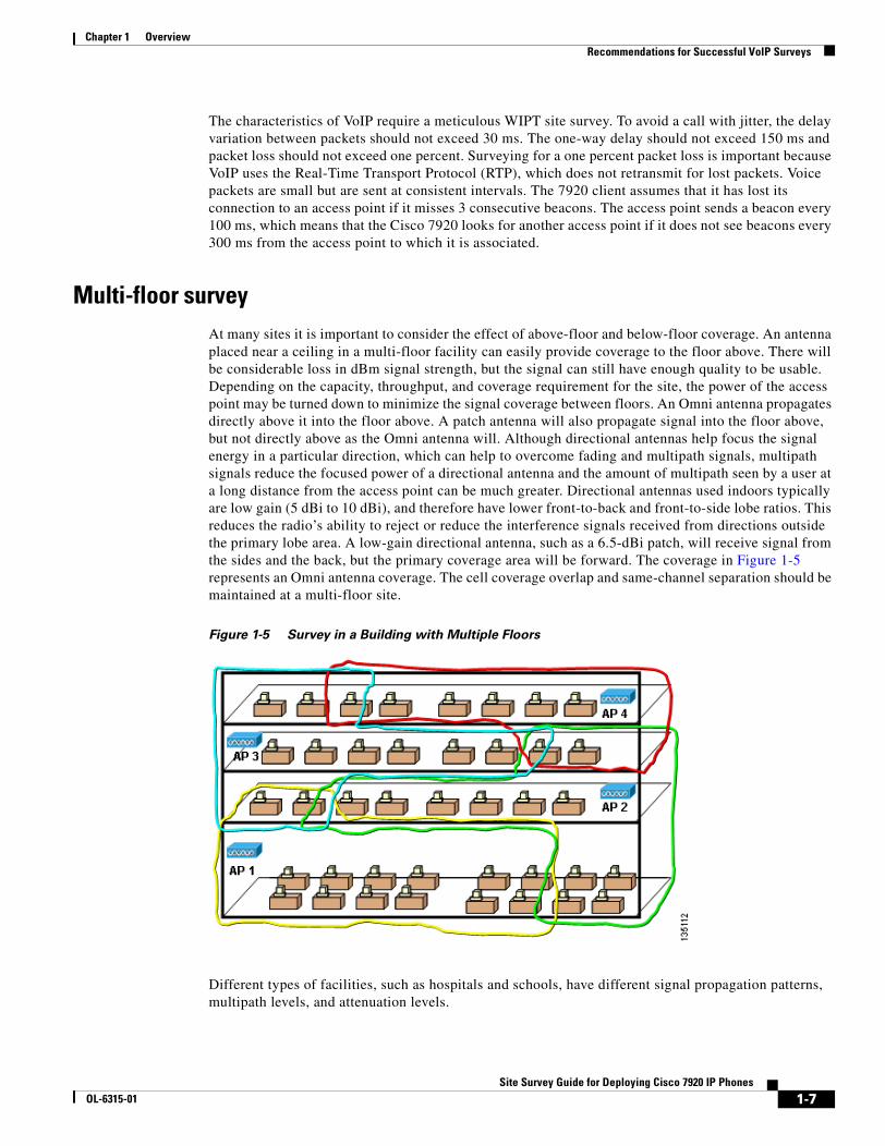
Multi-floor surveyAt many sites it is important to consider the effect of above-floor and below-floor coverage. An antenna placed near a ceiling in a multi-floor facility can easily provide coverage to the floor above. There will be considerable loss in dBm signal strength, but the signal can still have enough quality to be usable. Depending on the capacity, throughput, and coverage requirement for the site, the power of the access point may be turned down to minimize the signal coverage between floors. An Omni antenna propagates directly above it into the floor above. A patch antenna will also propagate signal into the floor above, but not directly above as the Omni antenna will. Although directional antennas help focus the signal energy in a particular direction, which can help to overcome fading and multipath signals, multipath signals reduce the focused power of a directional antenna and the amount of multipath seen by a user at a long distance from the access point can be much greater. Directional antennas used indoors typically are low gain (5 dBi to 10 dBi), and therefore have lower front-to-back and front-to-side lobe ratios. This reduces the radio’s ability to reject or reduce the interference signals received from directions outside the primary lobe area. A low-gain directional antenna, such as a 6.5-dBi patch, will receive signal from the sides and the back, but the primary coverage area will be forward. The coverage in Figure 1-5 represents an Omni antenna coverage. The cell coverage overlap and same-channel separation should be maintained at a multi-floor site.
Figure 1-5 Survey in a Building with Multiple Floors
Different types of facilities, such as hospitals and schools, have different signal propagation patterns, multipath levels, and attenuation levels.
1-7Site Survey Guide for Deploying Cisco 7920 IP Phones
OL-6315-01
Chapter 1 OverviewRecommendations for Successful VoIP Surveys
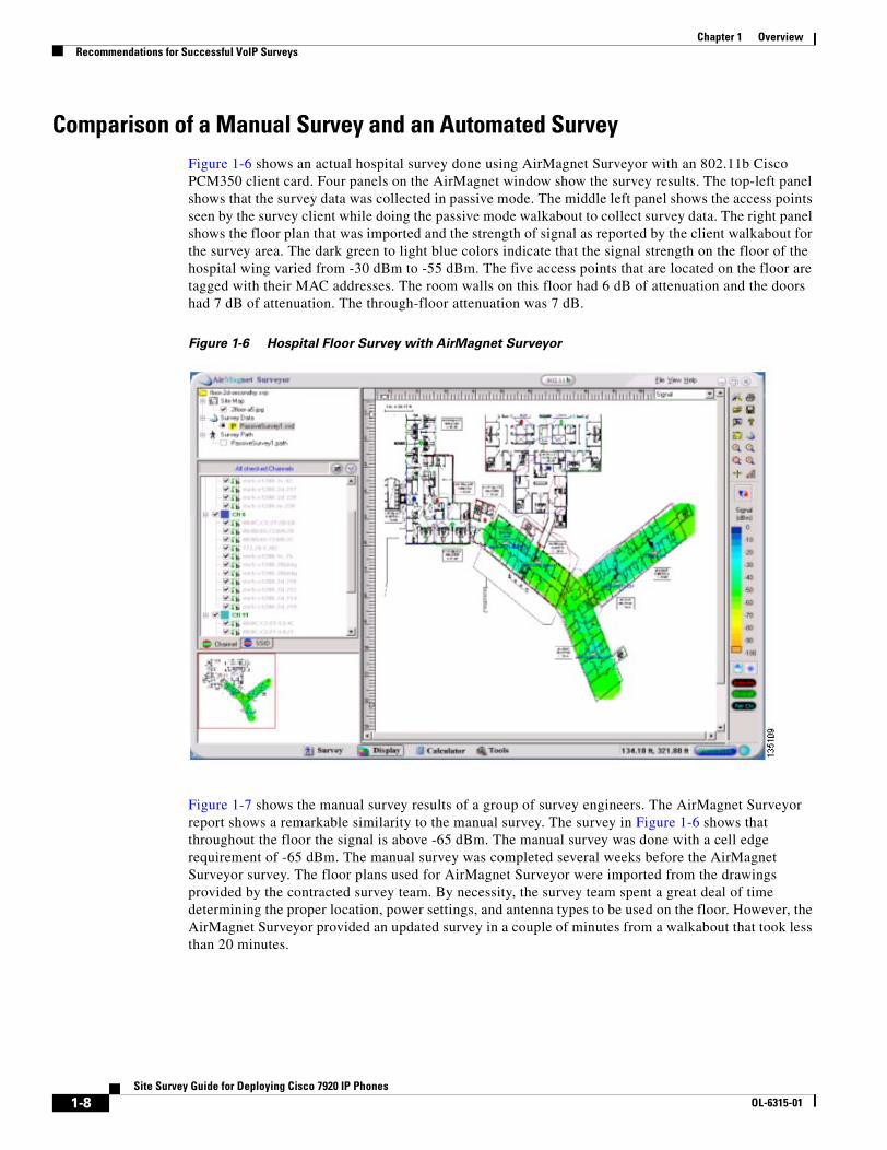
Comparison of a Manual Survey and an Automated Survey Figure 1-6 shows an actual hospital survey done using AirMagnet Surveyor with an 802.11b Cisco PCM350 client card. Four panels on the AirMagnet window show the survey results. The top-left panel shows that the survey data was collected in passive mode. The middle left panel shows the access points seen by the survey client while doing the passive mode walkabout to collect survey data. The right panel shows the floor plan that was imported and the strength of signal as reported by the client walkabout for the survey area. The dark green to light blue colors indicate that the signal strength on the floor of the hospital wing varied from -30 dBm to -55 dBm. The five access points that are located on the floor are tagged with their MAC addresses. The room walls on this floor had 6 dB of attenuation and the doors had 7 dB of attenuation. The through-floor attenuation was 7 dB.
Figure 1-6 Hospital Floor Survey with AirMagnet Surveyor
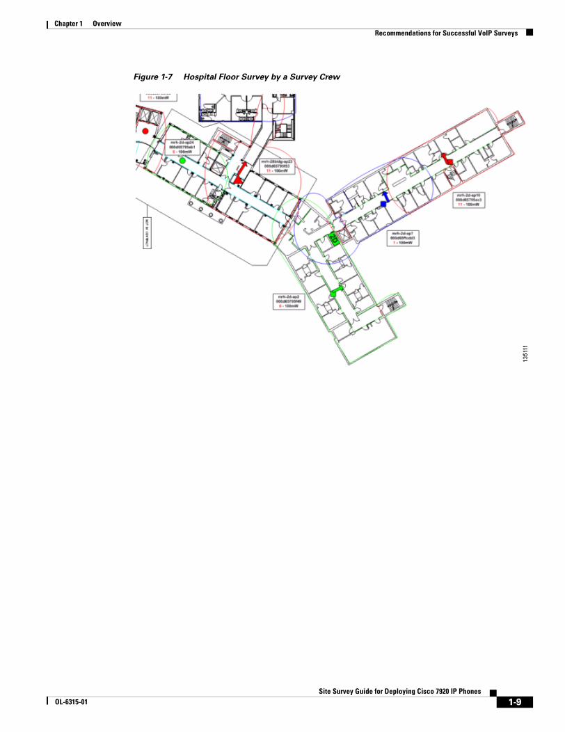
Figure 1-7 shows the manual survey results of a group of survey engineers. The AirMagnet Surveyor report shows a remarkable similarity to the manual survey. The survey in Figure 1-6 shows that throughout the floor the signal is above -65 dBm. The manual survey was done with a cell edge requirement of -65 dBm. The manual survey was completed several weeks before the AirMagnet Surveyor survey. The floor plans used for AirMagnet Surveyor were imported from the drawings provided by the contracted survey team. By necessity, the survey team spent a great deal of time determining the proper location, power settings, and antenna types to be used on the floor. However, the AirMagnet Surveyor provided an updated survey in a couple of minutes from a walkabout that took less than 20 minutes.
1-8Site Survey Guide for Deploying Cisco 7920 IP Phones
OL-6315-01
Chapter 1 OverviewRecommendations for Successful VoIP Surveys
Figure 1-7 Hospital Floor Survey by a Survey Crew
1-9Site Survey Guide for Deploying Cisco 7920 IP Phones
OL-6315-01
Chapter 1 OverviewRecommendations for Successful VoIP Surveys
1-10Site Survey Guide for Deploying Cisco 7920 IP Phones
OL-6315-01
Site Survey GuOL-6315-01
C H A P T E R 2
Survey Tools
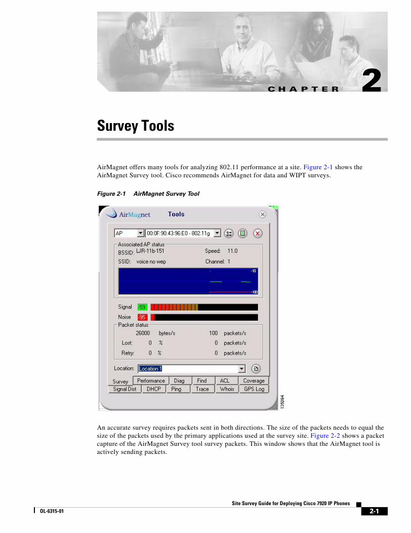
AirMagnet offers many tools for analyzing 802.11 performance at a site. Figure 2-1 shows the AirMagnet Survey tool. Cisco recommends AirMagnet for data and WIPT surveys.
Figure 2-1 AirMagnet Survey Tool
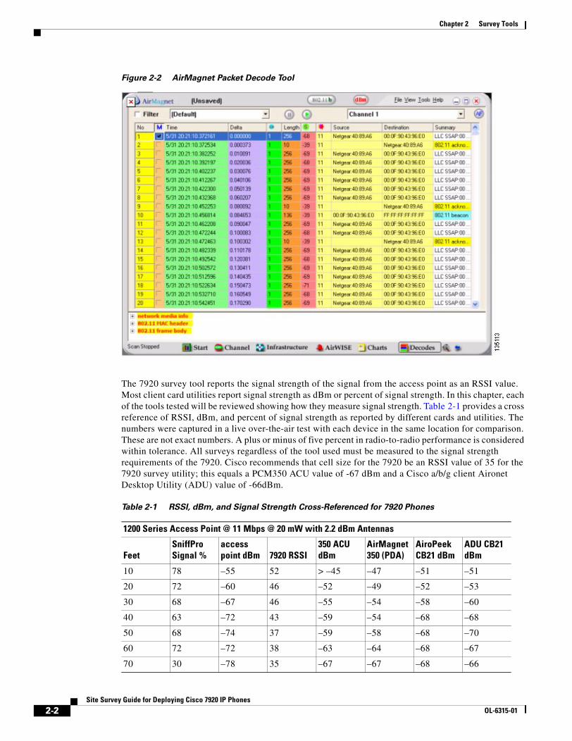
An accurate survey requires packets sent in both directions. The size of the packets needs to equal the size of the packets used by the primary applications used at the survey site. Figure 2-2 shows a packet capture of the AirMagnet Survey tool survey packets. This window shows that the AirMagnet tool is actively sending packets.
2-1ide for Deploying Cisco 7920 IP Phones
Chapter 2 Survey Tools
Figure 2-2 AirMagnet Packet Decode Tool
The 7920 survey tool reports the signal strength of the signal from the access point as an RSSI value. Most client card utilities report signal strength as dBm or percent of signal strength. In this chapter, each of the tools tested will be reviewed showing how they measure signal strength. Table 2-1 provides a cross reference of RSSI, dBm, and percent of signal strength as reported by different cards and utilities. The numbers were captured in a live over-the-air test with each device in the same location for comparison. These are not exact numbers. A plus or minus of five percent in radio-to-radio performance is considered within tolerance. All surveys regardless of the tool used must be measured to the signal strength requirements of the 7920. Cisco recommends that cell size for the 7920 be an RSSI value of 35 for the 7920 survey utility; this equals a PCM350 ACU value of -67 dBm and a Cisco a/b/g client Aironet Desktop Utility (ADU) value of -66dBm.
Table 2-1 RSSI, dBm, and Signal Strength Cross-Referenced for 7920 Phones
1200 Series Access Point @ 11 Mbps @ 20 mW with 2.2 dBm Antennas
FeetSniffPro Signal %
access point dBm 7920 RSSI
350 ACU dBm
AirMagnet 350 (PDA)
AiroPeek CB21 dBm
ADU CB21 dBm
10 78 –55 52 > –45 –47 –51 –51
20 72 –60 46 –52 –49 –52 –53
30 68 –67 46 –55 –54 –58 –60
40 63 –72 43 –59 –54 –68 –68
50 68 –74 37 –59 –58 –68 –70
60 72 –72 38 –63 –64 –68 –67
70 30 –78 35 –67 –67 –68 –66
2-2Site Survey Guide for Deploying Cisco 7920 IP Phones
OL-6315-01
Chapter 2 Survey Tools
The data in Table 2-1 was created from live tests. Each tool and card combination data point was taken at the same time from the same distance. The environment was an open office. The floor plan used for the test is shown in Figure 2-12.
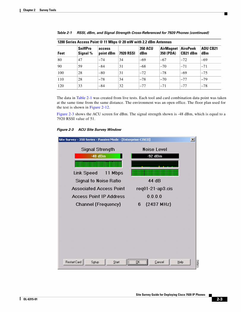
Figure 2-3 shows the ACU screen for dBm. The signal strength shown is -48 dBm, which is equal to a 7920 RSSI value of 51.
Figure 2-3 ACU Site Survey Window
80 47 –74 34 –69 –67 –72 –69
90 59 –84 31 –68 –70 –71 –71
100 28 –80 31 –72 –78 –69 –75
110 28 –78 34 –78 –70 –77 –79
120 33 –84 32 –77 –71 –77 –78
Table 2-1 RSSI, dBm, and Signal Strength Cross-Referenced for 7920 Phones (continued)
1200 Series Access Point @ 11 Mbps @ 20 mW with 2.2 dBm Antennas
FeetSniffPro Signal %
access point dBm 7920 RSSI
350 ACU dBm
AirMagnet 350 (PDA)
AiroPeek CB21 dBm
ADU CB21 dBm
2-3Site Survey Guide for Deploying Cisco 7920 IP Phones
OL-6315-01
Chapter 2 Survey Tools
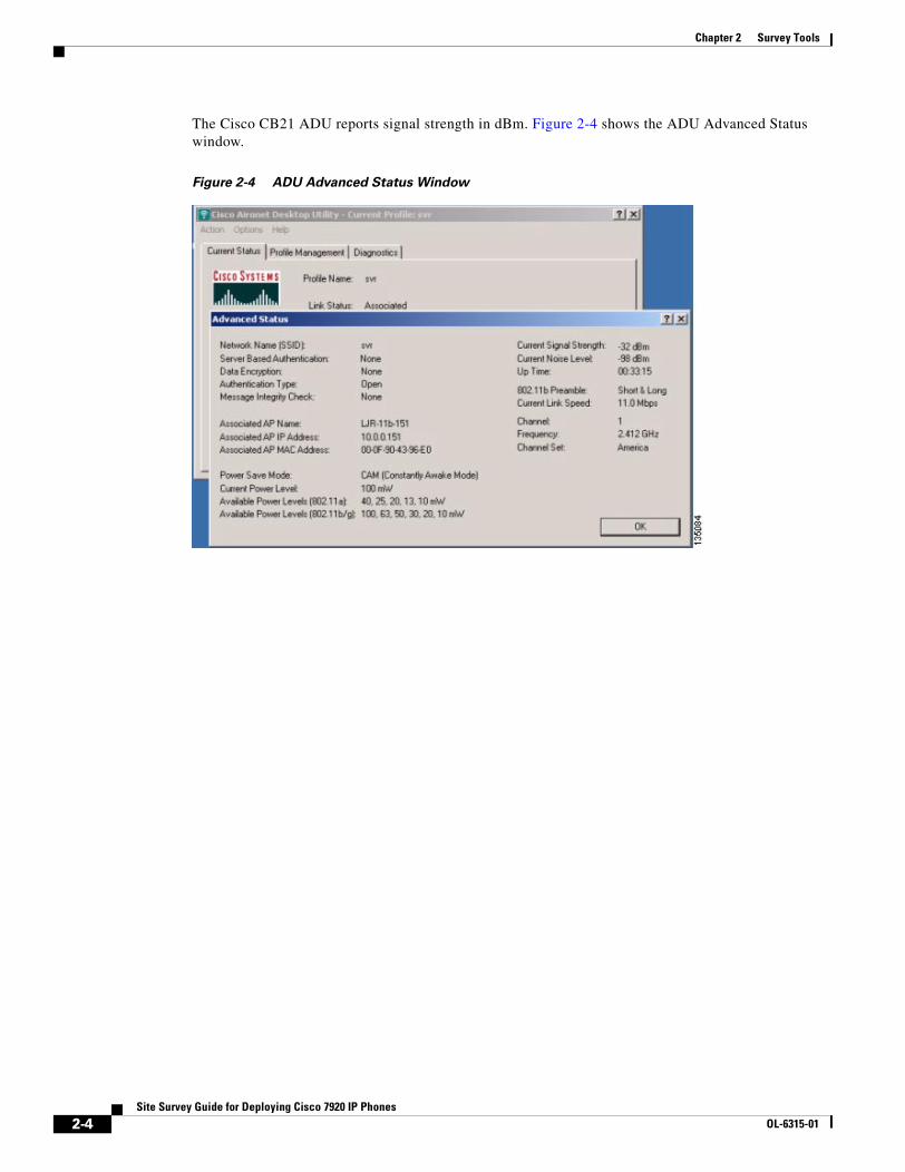
The Cisco CB21 ADU reports signal strength in dBm. Figure 2-4 shows the ADU Advanced Status window.
Figure 2-4 ADU Advanced Status Window
2-4Site Survey Guide for Deploying Cisco 7920 IP Phones
OL-6315-01
Chapter 2 Survey Tools
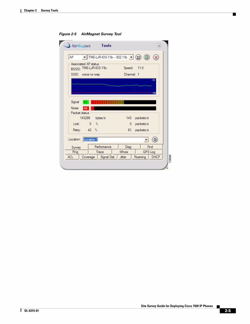
Figure 2-5 AirMagnet Survey Tool
2-5Site Survey Guide for Deploying Cisco 7920 IP Phones
OL-6315-01
Chapter 2 Survey Tools
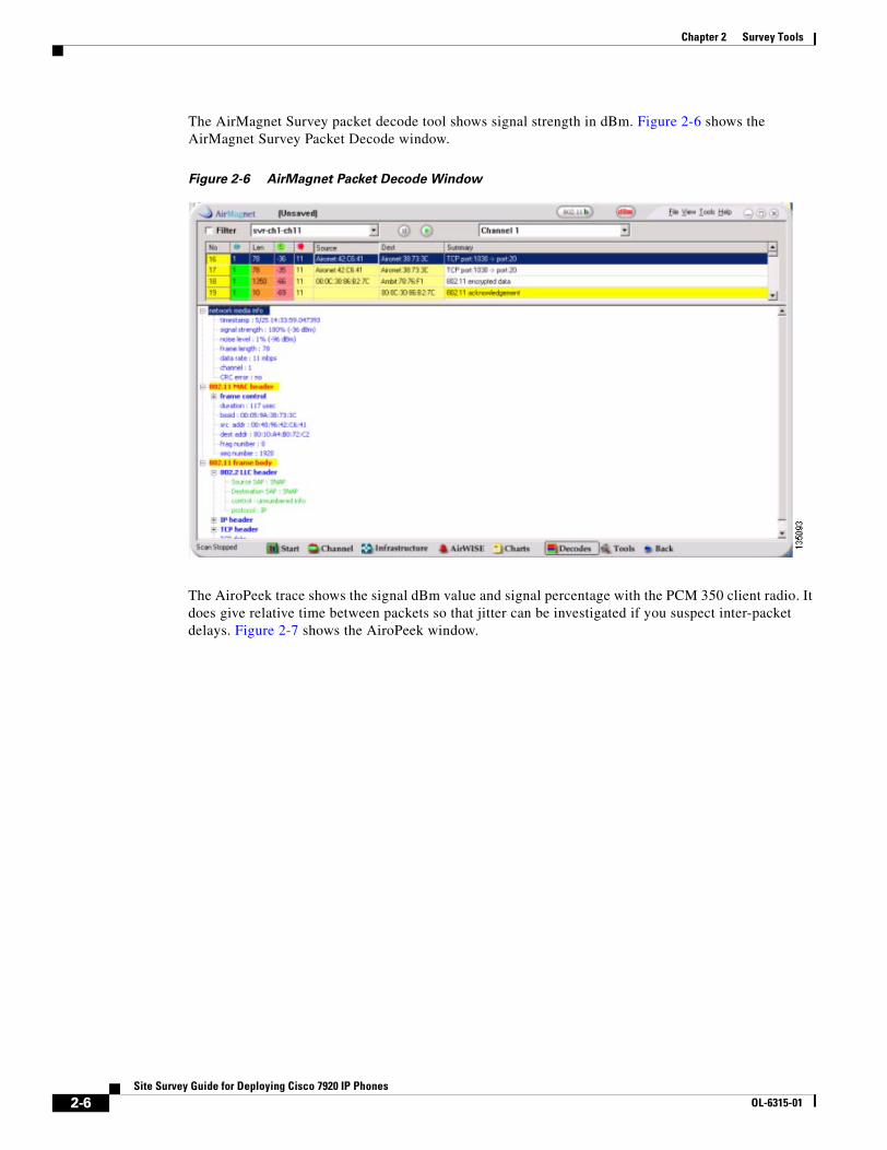
The AirMagnet Survey packet decode tool shows signal strength in dBm. Figure 2-6 shows the AirMagnet Survey Packet Decode window.
Figure 2-6 AirMagnet Packet Decode Window
The AiroPeek trace shows the signal dBm value and signal percentage with the PCM 350 client radio. It does give relative time between packets so that jitter can be investigated if you suspect inter-packet delays. Figure 2-7 shows the AiroPeek window.
2-6Site Survey Guide for Deploying Cisco 7920 IP Phones
OL-6315-01
Chapter 2 Survey Tools
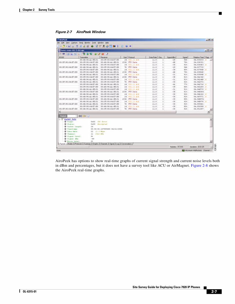
Figure 2-7 AiroPeek Window
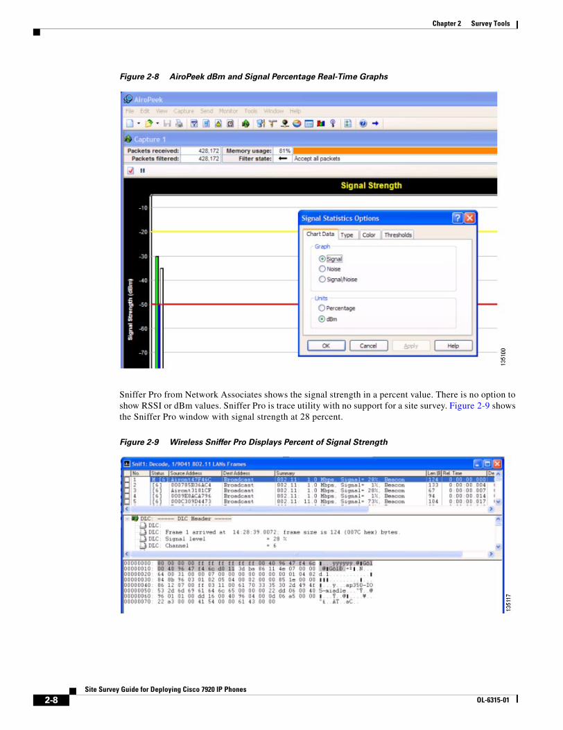
AiroPeek has options to show real-time graphs of current signal strength and current noise levels both in dBm and percentages, but it does not have a survey tool like ACU or AirMagnet. Figure 2-8 shows the AiroPeek real-time graphs.
2-7Site Survey Guide for Deploying Cisco 7920 IP Phones
OL-6315-01
Chapter 2 Survey Tools
Figure 2-8 AiroPeek dBm and Signal Percentage Real-Time Graphs
Sniffer Pro from Network Associates shows the signal strength in a percent value. There is no option to show RSSI or dBm values. Sniffer Pro is trace utility with no support for a site survey. Figure 2-9 shows the Sniffer Pro window with signal strength at 28 percent.
Figure 2-9 Wireless Sniffer Pro Displays Percent of Signal Strength
2-8Site Survey Guide for Deploying Cisco 7920 IP Phones
OL-6315-01
Chapter 2 Survey Tools
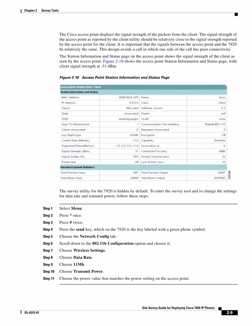
The Cisco access point displays the signal strength of the packets from the client. The signal strength of the access point as reported by the client utility should be relatively close to the signal strength reported by the access point for the client. It is important that the signals between the access point and the 7920 be relatively the same. This design avoids a call in which one side of the call has poor connectivity.
The Station Information and Status page on the access point shows the signal strength of the client as seen by the access point. Figure 2-10 shows the access point Station Information and Status page, with client signal strength at -31 dBm.
Figure 2-10 Access Point Station Information and Status Page
The survey utility for the 7920 is hidden by default. To enter the survey tool and to change the settings for data rate and transmit power, follow these steps:
Step 1 Select Menu.
Step 2 Press * once.
Step 3 Press # twice.
Step 4 Press the send key, which on the 7920 is the key labeled with a green phone symbol.
Step 5 Choose the Network Config tab.
Step 6 Scroll down to the 802.11b Configuration option and choose it.
Step 7 Choose Wireless Settings.
Step 8 Choose Data Rate.
Step 9 Choose 11Mb.
Step 10 Choose Transmit Power.
Step 11 Choose the power value that matches the power setting on the access point.
2-9Site Survey Guide for Deploying Cisco 7920 IP Phones
OL-6315-01
Chapter 2 Survey Tools
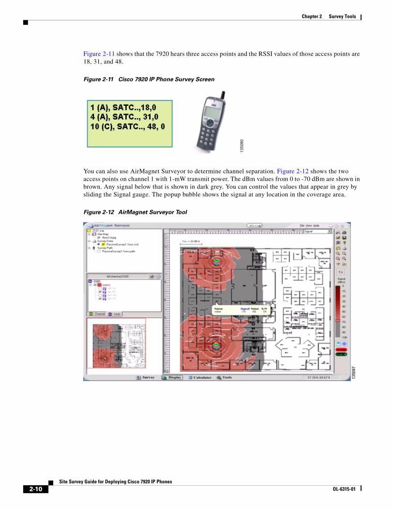
Figure 2-11 shows that the 7920 hears three access points and the RSSI values of those access points are 18, 31, and 48.
Figure 2-11 Cisco 7920 IP Phone Survey Screen
You can also use AirMagnet Surveyor to determine channel separation. Figure 2-12 shows the two access points on channel 1 with 1-mW transmit power. The dBm values from 0 to -70 dBm are shown in brown. Any signal below that is shown in dark grey. You can control the values that appear in grey by sliding the Signal gauge. The popup bubble shows the signal at any location in the coverage area.
Figure 2-12 AirMagnet Surveyor Tool
2-10Site Survey Guide for Deploying Cisco 7920 IP Phones
OL-6315-01
Chapter 2 Survey ToolsSurvey Tools for Packet Jitter
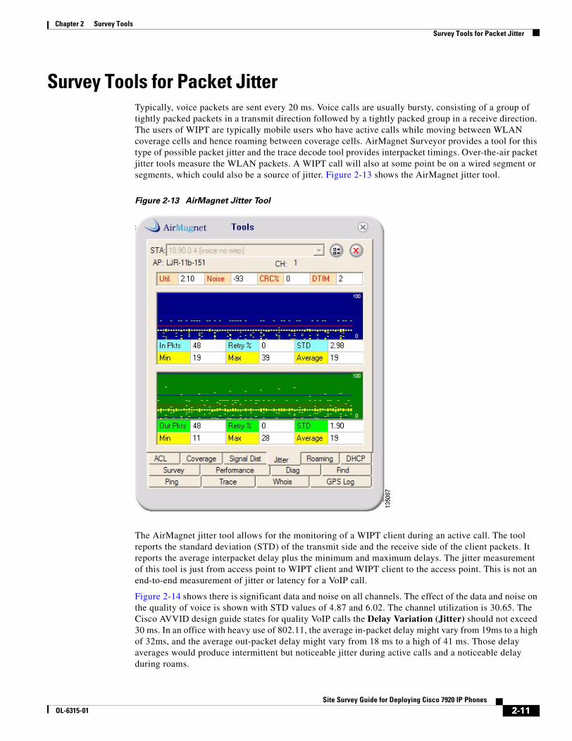
Survey Tools for Packet Jitter Typically, voice packets are sent every 20 ms. Voice calls are usually bursty, consisting of a group of tightly packed packets in a transmit direction followed by a tightly packed group in a receive direction. The users of WIPT are typically mobile users who have active calls while moving between WLAN coverage cells and hence roaming between coverage cells. AirMagnet Surveyor provides a tool for this type of possible packet jitter and the trace decode tool provides interpacket timings. Over-the-air packet jitter tools measure the WLAN packets. A WIPT call will also at some point be on a wired segment or segments, which could also be a source of jitter. Figure 2-13 shows the AirMagnet jitter tool.
Figure 2-13 AirMagnet Jitter Tool
The AirMagnet jitter tool allows for the monitoring of a WIPT client during an active call. The tool reports the standard deviation (STD) of the transmit side and the receive side of the client packets. It reports the average interpacket delay plus the minimum and maximum delays. The jitter measurement of this tool is just from access point to WIPT client and WIPT client to the access point. This is not an end-to-end measurement of jitter or latency for a VoIP call.
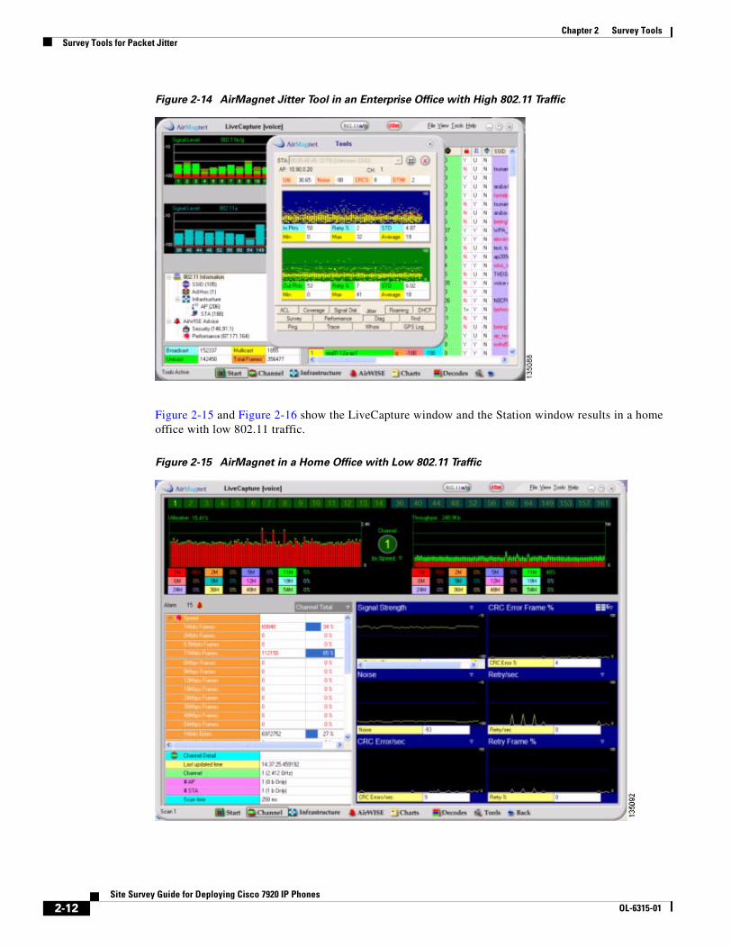
Figure 2-14 shows there is significant data and noise on all channels. The effect of the data and noise on the quality of voice is shown with STD values of 4.87 and 6.02. The channel utilization is 30.65. The Cisco AVVID design guide states for quality VoIP calls the Delay Variation (Jitter) should not exceed 30 ms. In an office with heavy use of 802.11, the average in-packet delay might vary from 19ms to a high of 32ms, and the average out-packet delay might vary from 18 ms to a high of 41 ms. Those delay averages would produce intermittent but noticeable jitter during active calls and a noticeable delay during roams.
2-11Site Survey Guide for Deploying Cisco 7920 IP Phones
OL-6315-01
Chapter 2 Survey ToolsSurvey Tools for Packet Jitter
Figure 2-14 AirMagnet Jitter Tool in an Enterprise Office with High 802.11 Traffic
Figure 2-15 and Figure 2-16 show the LiveCapture window and the Station window results in a home office with low 802.11 traffic.
Figure 2-15 AirMagnet in a Home Office with Low 802.11 Traffic
2-12Site Survey Guide for Deploying Cisco 7920 IP Phones
OL-6315-01
Chapter 2 Survey ToolsSurvey Tools for Packet Jitter
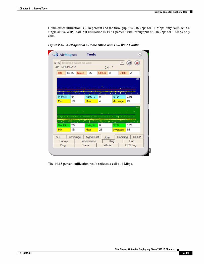
Home office utilization is 2.18 percent and the throughput is 246 kbps for 11 Mbps-only calls, with a single active WIPT call, but utilization is 15.41 percent with throughput of 248 kbps for 1 Mbps-only calls.
Figure 2-16 AirMagnet in a Home Office with Low 802.11 Traffic
The 14.15 percent utilization result reflects a call at 1 Mbps.
2-13Site Survey Guide for Deploying Cisco 7920 IP Phones
OL-6315-01
Chapter 2 Survey ToolsSurvey Tools for Packet Jitter
2-14Site Survey Guide for Deploying Cisco 7920 IP Phones
OL-6315-01
Site Survey GuOL-6315-01
C H A P T E R 3
Surveying for Cell Capacity and Channel Re-Use
This chapter describes how to perform a site survey to design a wireless LAN for cell capacity and channel re-use.
Survey Design for Cell CapacityCisco recommends that you install enough access points to provide all users with quality calls. Maintaining high call quality might require small coverage cells that limit the number of calls per access point to 7 to meet the QBSS level on access points below 35. With a recommended RSSI level of 20 dB throughout the RF network, the access point transmit powers could be as low as 20mW, with low-gain antennas on the access points. You should consider these design factors to ensure adequate capacity and coverage:
• removing interfering devices
• configuring older 802.11 devices to lower transmit power
• configuring older 802.11 devices to the highest possible data rate
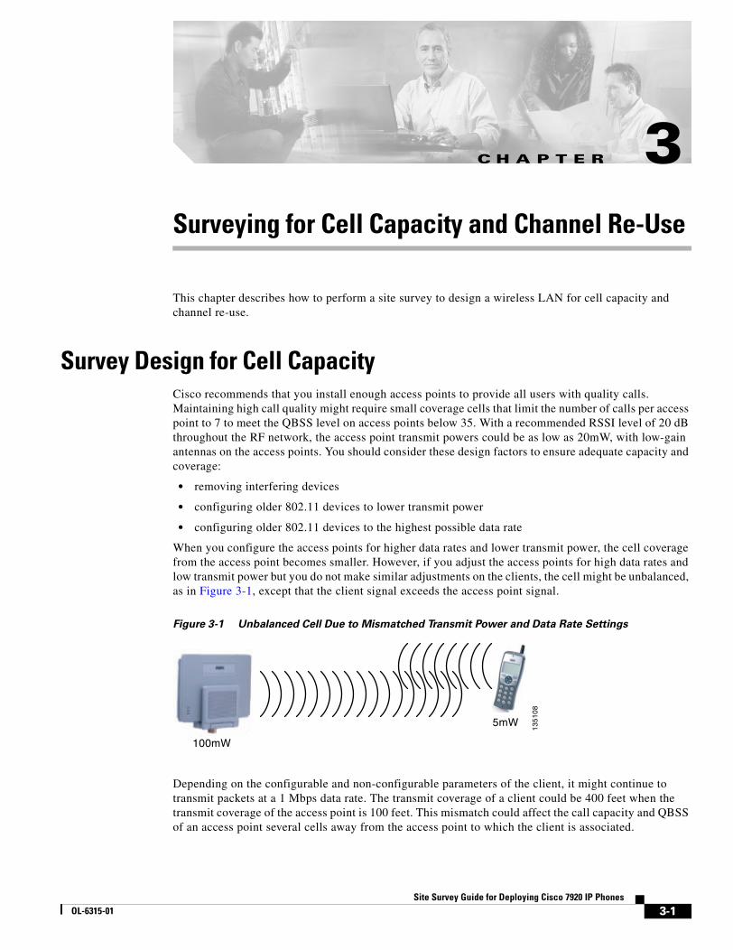
When you configure the access points for higher data rates and lower transmit power, the cell coverage from the access point becomes smaller. However, if you adjust the access points for high data rates and low transmit power but you do not make similar adjustments on the clients, the cell might be unbalanced, as in Figure 3-1, except that the client signal exceeds the access point signal.
Figure 3-1 Unbalanced Cell Due to Mismatched Transmit Power and Data Rate Settings
Depending on the configurable and non-configurable parameters of the client, it might continue to transmit packets at a 1 Mbps data rate. The transmit coverage of a client could be 400 feet when the transmit coverage of the access point is 100 feet. This mismatch could affect the call capacity and QBSS of an access point several cells away from the access point to which the client is associated.
100mW
5mW
1351
08
3-1ide for Deploying Cisco 7920 IP Phones
Chapter 3 Surveying for Cell Capacity and Channel Re-UseSurvey Design for Cell Capacity
Note If the Cisco access point is configured to disable data rates 1, 2, and 5.5, clients are not required to transmit only at 11 Mbps. In fact, older client devices might not be programmed to recognize the access point configuration for data rates.
Cisco recommends that customers update their 802.11 clients to run the newest firmware and drivers available. Vendors generally update power and data rate options as their products mature.
3-2Site Survey Guide for Deploying Cisco 7920 IP Phones
OL-6315-01
Site Survey GuOL-6315-01
C H A P T E R 4
Conducting a WIPT Survey
This chapter describes specific steps for performing a site survey for WIPT.
How To Survey for the WIPTCisco recommends that the first step of a survey is to work with administrators at the local site to determine the requirements of the RF network. Determine what the coverage areas are or will become. Determine the number of RF network users by location in the site. If the site already has an active RF network, learn the site’s radio frequencies, equipment locations, and equipment characteristics. Next, do a complete scan for RF signals throughout the site. Determine the levels of RF at the site, and verify that the information you’ve been given about the locations of RF devices is correct. Report your findings to the site administrators.
Cisco recommends that the next step is to find on the drawings the locations of the existing RF devices. Use the drawings to estimate the cells based on the requirements for 7920 call capacities and cell design. Plan the antennas needed and transmit powers required for the access points within the site. When surveying with an existing WLAN, plan for the areas to be filled in and for changes to existing data rate and transmit power settings. Plan on possible changes to antenna types. At a multi-floor site, plan the survey of the coverage for the floor above and below. When doing a manual survey, record the cell edges of the current floor and then use your survey tool on other floors to measure and record the signal levels. When doing an automated survey, include the access point on the floors above and below in the walk-through survey.
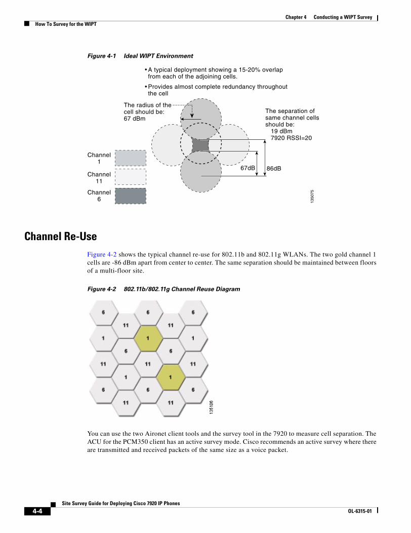
When you survey a site without an installed 802.11 network, plan to use two or three access points to measure cell coverage and cell overlap. The cell edge for the 7920 at the 11-Mbps data rate is -67 dBm. The signal strength at the edge of that cell needs to be 19 dB weaker than the signal from the next cell on the same channel. That means at the -67 dBm edge of the cell, the next cell on the same channel should measure -86 dBm, as shown in Figure 4-1.
4-3ide for Deploying Cisco 7920 IP Phones
Chapter 4 Conducting a WIPT SurveyHow To Survey for the WIPT
Figure 4-1 Ideal WIPT Environment
Channel Re-UseFigure 4-2 shows the typical channel re-use for 802.11b and 802.11g WLANs. The two gold channel 1 cells are -86 dBm apart from center to center. The same separation should be maintained between floors of a multi-floor site.
Figure 4-2 802.11b/802.11g Channel Reuse Diagram
You can use the two Aironet client tools and the survey tool in the 7920 to measure cell separation. The ACU for the PCM350 client has an active survey mode. Cisco recommends an active survey where there are transmitted and received packets of the same size as a voice packet.
A typical deployment showing a 15-20% overlapfrom each of the adjoining cells.
Provides almost complete redundancy throughoutthe cell
The radius of thecell should be:67 dBm
The separation ofsame channel cellsshould be: 19 dBm 7920 RSSI=20
67dB 86dB
1350
75
Channel1
Channel11
Channel6
4-4Site Survey Guide for Deploying Cisco 7920 IP Phones
OL-6315-01
Chapter 4 Conducting a WIPT SurveyHow To Survey for the WIPT
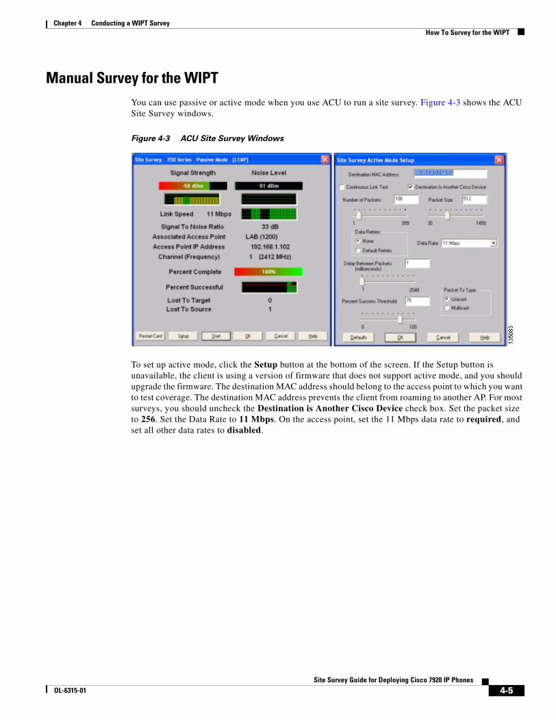
Manual Survey for the WIPTYou can use passive or active mode when you use ACU to run a site survey. Figure 4-3 shows the ACU Site Survey windows.
Figure 4-3 ACU Site Survey Windows
To set up active mode, click the Setup button at the bottom of the screen. If the Setup button is unavailable, the client is using a version of firmware that does not support active mode, and you should upgrade the firmware. The destination MAC address should belong to the access point to which you want to test coverage. The destination MAC address prevents the client from roaming to another AP. For most surveys, you should uncheck the Destination is Another Cisco Device check box. Set the packet size to 256. Set the Data Rate to 11 Mbps. On the access point, set the 11 Mbps data rate to required, and set all other data rates to disabled.
4-5Site Survey Guide for Deploying Cisco 7920 IP Phones
OL-6315-01
Chapter 4 Conducting a WIPT SurveyHow To Survey for the WIPT
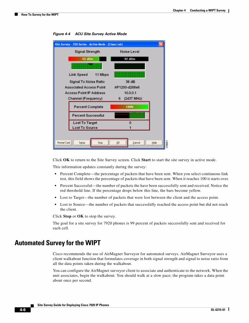
Figure 4-4 ACU Site Survey Active Mode
Click OK to return to the Site Survey screen. Click Start to start the site survey in active mode.
This information updates constantly during the survey:
• Percent Complete—the percentage of packets that have been sent. When you select continuous link test, this field shows the percentage of packets that have been sent. When it reaches 100 it starts over.
• Percent Successful—the number of packets the have been successfully sent and received. Notice the red threshold line. If the percentage drops below this line, the bars become yellow.
• Lost to Target—the number of packets that were lost between the client and the access point.
• Lost to Source—the number of packets that successfully reached the access point but did not reach the client.
Click Stop or OK to stop the survey.
The goal for a site survey for 7920 phones is 99 percent of packets successfully sent and received for each cell.
Automated Survey for the WIPTCisco recommends the use of AirMagnet Surveyor for automated surveys. AirMagnet Surveyor uses a client walkabout function that formulates coverage in both signal strength and signal to noise ratio from all the data points taken during the walkabout.
You can configure the AirMagnet surveyor client to associate and authenticate to the network. When the unit associates, begin the walkabout. You should walk at a slow pace; the program takes a data point about once per second.
4-6Site Survey Guide for Deploying Cisco 7920 IP Phones
OL-6315-01
Chapter 4 Conducting a WIPT SurveyHow To Survey for the WIPT
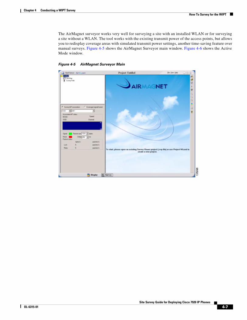
The AirMagnet surveyor works very well for surveying a site with an installed WLAN or for surveying a site without a WLAN. The tool works with the existing transmit power of the access points, but allows you to redisplay coverage areas with simulated transmit power settings, another time-saving feature over manual surveys. Figure 4-5 shows the AirMagnet Surveyor main window. Figure 4-6 shows the Active Mode window.
Figure 4-5 AirMagnet Surveyor Main
4-7Site Survey Guide for Deploying Cisco 7920 IP Phones
OL-6315-01
Chapter 4 Conducting a WIPT SurveyHow To Survey for the WIPT
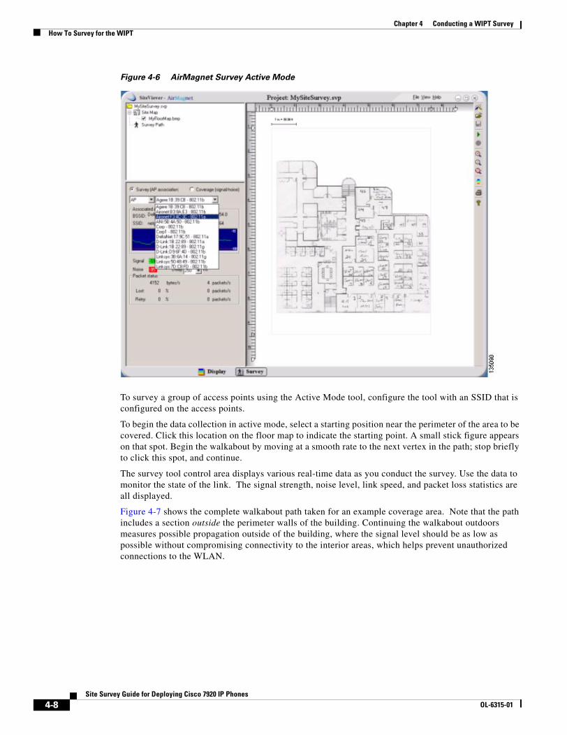
Figure 4-6 AirMagnet Survey Active Mode
To survey a group of access points using the Active Mode tool, configure the tool with an SSID that is configured on the access points.
To begin the data collection in active mode, select a starting position near the perimeter of the area to be covered. Click this location on the floor map to indicate the starting point. A small stick figure appears on that spot. Begin the walkabout by moving at a smooth rate to the next vertex in the path; stop briefly to click this spot, and continue.
The survey tool control area displays various real-time data as you conduct the survey. Use the data to monitor the state of the link. The signal strength, noise level, link speed, and packet loss statistics are all displayed.
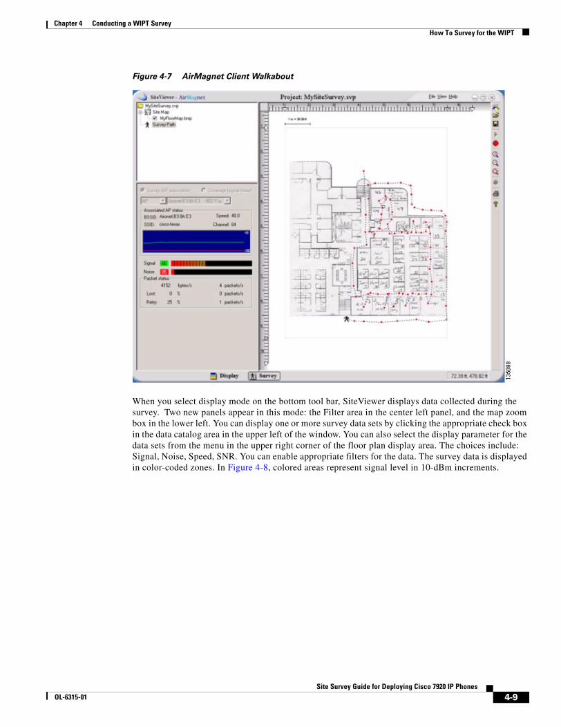
Figure 4-7 shows the complete walkabout path taken for an example coverage area. Note that the path includes a section outside the perimeter walls of the building. Continuing the walkabout outdoors measures possible propagation outside of the building, where the signal level should be as low as possible without compromising connectivity to the interior areas, which helps prevent unauthorized connections to the WLAN.
4-8Site Survey Guide for Deploying Cisco 7920 IP Phones
OL-6315-01
Chapter 4 Conducting a WIPT SurveyHow To Survey for the WIPT
Figure 4-7 AirMagnet Client Walkabout
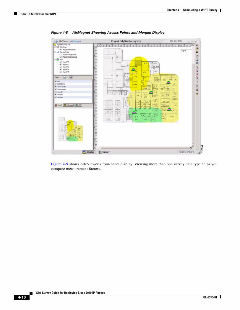
When you select display mode on the bottom tool bar, SiteViewer displays data collected during the survey. Two new panels appear in this mode: the Filter area in the center left panel, and the map zoom box in the lower left. You can display one or more survey data sets by clicking the appropriate check box in the data catalog area in the upper left of the window. You can also select the display parameter for the data sets from the menu in the upper right corner of the floor plan display area. The choices include: Signal, Noise, Speed, SNR. You can enable appropriate filters for the data. The survey data is displayed in color-coded zones. In Figure 4-8, colored areas represent signal level in 10-dBm increments.
4-9Site Survey Guide for Deploying Cisco 7920 IP Phones
OL-6315-01
Chapter 4 Conducting a WIPT SurveyHow To Survey for the WIPT
Figure 4-8 AirMagnet Showing Access Points and Merged Display
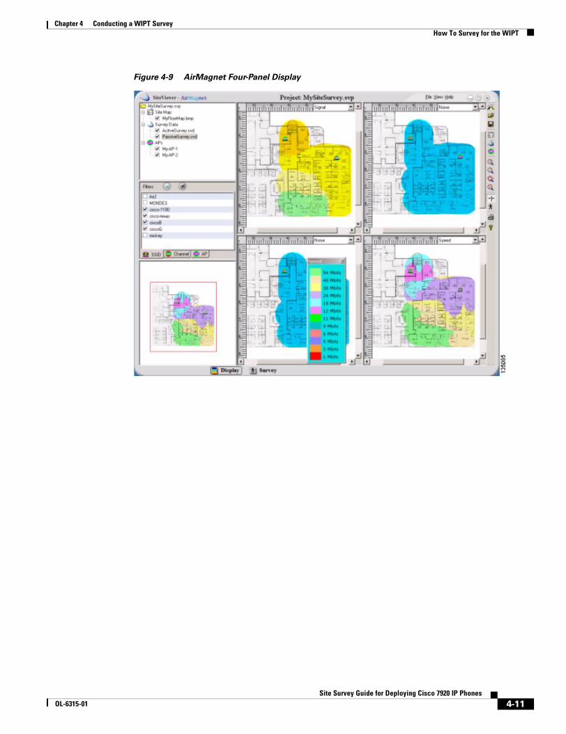
Figure 4-9 shows SiteViewer’s four-panel display. Viewing more than one survey data type helps you compare measurement factors.
4-10Site Survey Guide for Deploying Cisco 7920 IP Phones
OL-6315-01
Chapter 4 Conducting a WIPT SurveyHow To Survey for the WIPT
Figure 4-9 AirMagnet Four-Panel Display
4-11Site Survey Guide for Deploying Cisco 7920 IP Phones
OL-6315-01
Chapter 4 Conducting a WIPT SurveyHow To Survey for the WIPT
4-12Site Survey Guide for Deploying Cisco 7920 IP Phones
OL-6315-01
Site Survey GuOL-6315-01
C H A P T E R 5
Positioning Access Points and Antennas for Site Surveys
When you perform a site survey, it is important to position wireless equipment for optimal coverage. This chapter describes best practices for positioning access points and antennas.
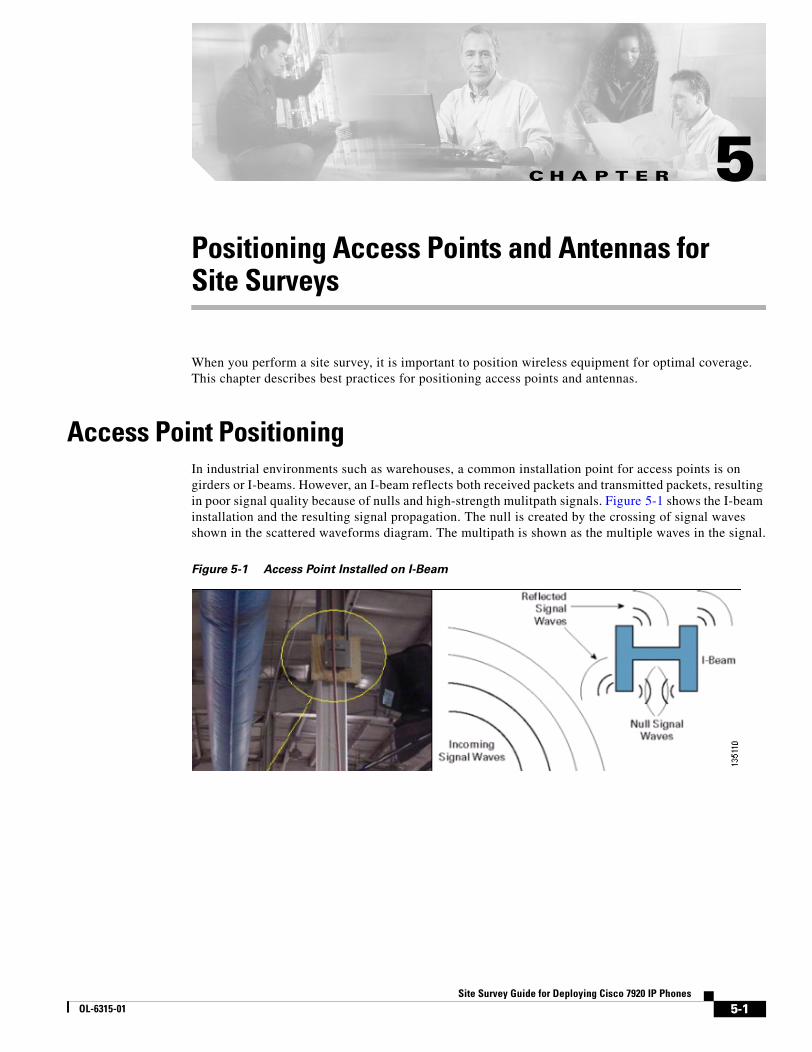
Access Point PositioningIn industrial environments such as warehouses, a common installation point for access points is on girders or I-beams. However, an I-beam reflects both received packets and transmitted packets, resulting in poor signal quality because of nulls and high-strength mulitpath signals. Figure 5-1 shows the I-beam installation and the resulting signal propagation. The null is created by the crossing of signal waves shown in the scattered waveforms diagram. The multipath is shown as the multiple waves in the signal.
Figure 5-1 Access Point Installed on I-Beam
5-1ide for Deploying Cisco 7920 IP Phones
Chapter 5 Positioning Access Points and Antennas for Site SurveysAntennas and Antenna Positioning
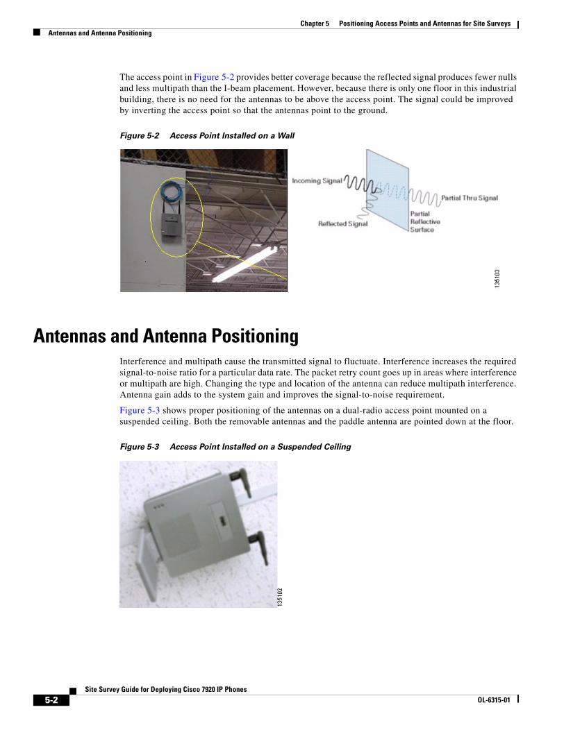
The access point in Figure 5-2 provides better coverage because the reflected signal produces fewer nulls and less multipath than the I-beam placement. However, because there is only one floor in this industrial building, there is no need for the antennas to be above the access point. The signal could be improved by inverting the access point so that the antennas point to the ground.
Figure 5-2 Access Point Installed on a Wall
Antennas and Antenna PositioningInterference and multipath cause the transmitted signal to fluctuate. Interference increases the required signal-to-noise ratio for a particular data rate. The packet retry count goes up in areas where interference or multipath are high. Changing the type and location of the antenna can reduce multipath interference. Antenna gain adds to the system gain and improves the signal-to-noise requirement.
Figure 5-3 shows proper positioning of the antennas on a dual-radio access point mounted on a suspended ceiling. Both the removable antennas and the paddle antenna are pointed down at the floor.
Figure 5-3 Access Point Installed on a Suspended Ceiling
5-2Site Survey Guide for Deploying Cisco 7920 IP Phones
OL-6315-01
Chapter 5 Positioning Access Points and Antennas for Site SurveysAntennas and Antenna Positioning
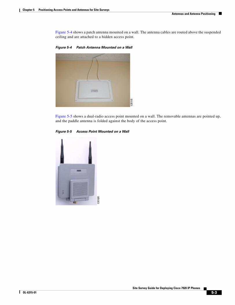
Figure 5-4 shows a patch antenna mounted on a wall. The antenna cables are routed above the suspended ceiling and are attached to a hidden access point.
Figure 5-4 Patch Antenna Mounted on a Wall
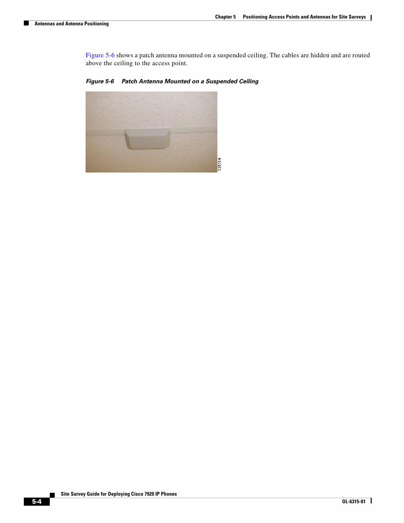
Figure 5-5 shows a dual-radio access point mounted on a wall. The removable antennas are pointed up, and the paddle antenna is folded against the body of the access point.
Figure 5-5 Access Point Mounted on a Wall
5-3Site Survey Guide for Deploying Cisco 7920 IP Phones
OL-6315-01
Chapter 5 Positioning Access Points and Antennas for Site SurveysAntennas and Antenna Positioning
Figure 5-6 shows a patch antenna mounted on a suspended ceiling. The cables are hidden and are routed above the ceiling to the access point.
Figure 5-6 Patch Antenna Mounted on a Suspended Ceiling
5-4Site Survey Guide for Deploying Cisco 7920 IP Phones
OL-6315-01
Site Survey GuOL-6315-01
A P P E N D I X A
Additional Sources of Information
This appendix lists documents that provide additional information about site surveys:
• Cisco Wireless IP Phone 7920 Deployment Recommendations