56
1 SITE INVESTIGATION
| Date post: | 16-Jul-2015 |
| Category: |
Documents |
| Upload: | abhishek-sagar |
| View: | 98 times |
| Download: | 0 times |

1
SITE INVESTIGATION
2
Definition
The process of determining the layers of natural soil deposits that will underlie a proposed structure and their physical properties is generally referred to as site investigation.

3
The purpose of a soil investigation program 1. Selection of the type and the depth of foundation
suitable for a given structure.2. Evaluation of the load-bearing capacity of the
foundation.3. Estimation of the probable settlement of a structure.4. Determination of potential foundation problems (for
example, expansive soil, collapsible soil, sanitary landfill, and so on).
5. Establishment of ground water table.6. Prediction of lateral earth pressure for structures like
retaining walls, sheet pile bulkheads, and braced cuts.
7. Establishment of construction methods for changing subsoil conditions.

4
EXPLORATION PROGRAM The purpose of the exploration program
is to determine, within practical limits, the stratification and engineering properties of the soils underlying the site. The principal properties of interest will be the strength, deformation, and hydraulic characteristics. The program should be planned so that the maximum amount of information can be obtained at minimum cost.

5
Steps of subsurface exploration program [Stage 1] 1.Assembly of all available information on
dimensions, column spacing, type and use of the structure, basement requirements, and any special architectural considerations of the proposed building. Foundation regulations in the local building code should be consulted for any special requirements. For bridges the soil engineer should have access to type and span lengths as well as pier loadings. This information will indicate any settlement limitations, and can be used to estimate foundation loads.
6
Steps of subsurface exploration program [Stage 2]
2.Reconnaissance of the area: This may be in the form of a field trip to the
site which can reveal information on the type and behavior of adjacent structures such as cracks, noticeable sags, and possibly sticking doors and windows. The type of local existing structure may influence, to a considerable extent, the exploration program and the best foundation type for the proposed adjacent structure.

7
Steps of subsurface exploration program [Stage 3]
3.A preliminary site investigation: In this phase a few borings are made or a test
pit is opened to establish in a general manner the stratification, types of soil to be expected, and possibly the location of the groundwater table. One or more borings should be taken to rock, or competent strata, if the initial borings indicate the upper soil is loose or highly compressible. This amount of exploration is usually the extent of the site investigation for small structures.

8
Steps of subsurface exploration program [Stage 4]
4.A detailed site investigation: Where the preliminary site investigation
has established the feasibility of the project, a more detailed exploration program is undertaken. The preliminary borings and data are used as a basis for locating additional borings, which should be confirmatory in nature, and determining the additional samples required.
9
Depth of Boring
The approximate required minimum depth of the borings should be predetermined. The estimated depths can be changed during the drilling operation, depending on the subsoil encountered. To determine the approximate minimum depth of boring, engineers may use the following rule:
10
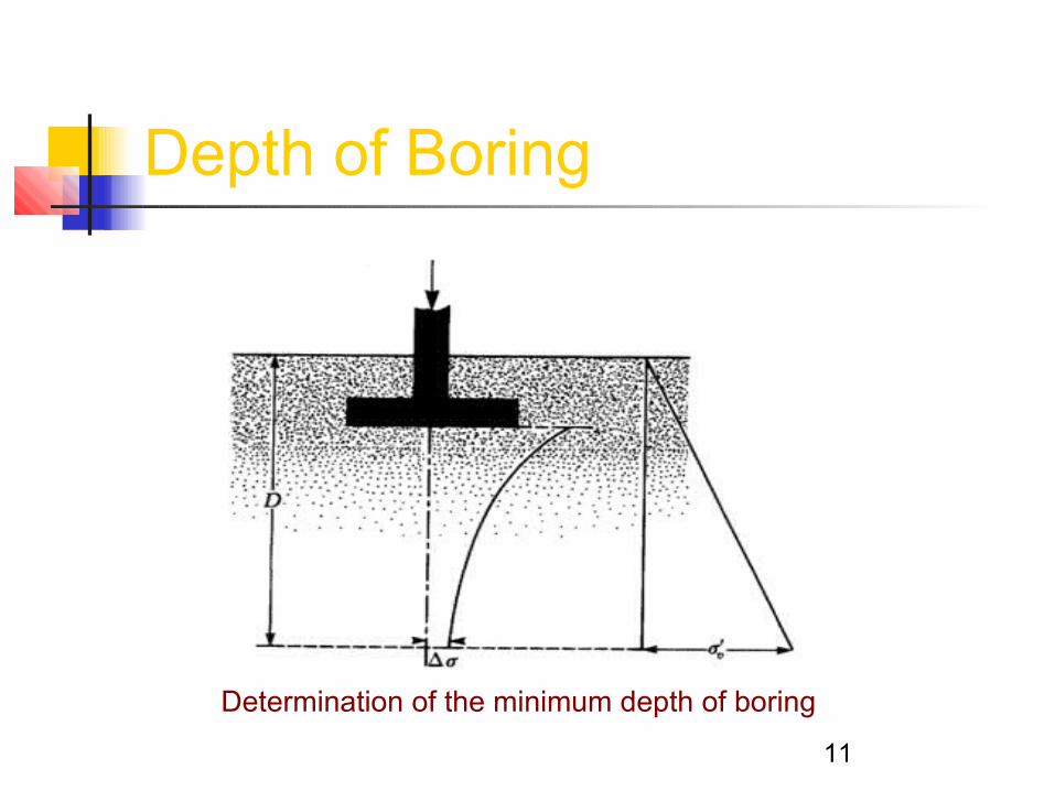
Depth of Boring1. Determine the net increase of stress,∆σ under a
foundation with depth as shown in the Figure. 2. Estimate the variation of the vertical effective stress,
σ'υ, with depth. 3. Determine the depth, D = D1, at which the stress
increase ∆σ is equal to (1/10) q (q = estimated net stress on the foundation).
4. Determine the depth, D = D2, at which ∆σ/σ'υ = 0.05.5. Unless bedrock is encountered, the smaller of the
two depths, D1 and D2, just determined is the approximate minimum depth of boring required. Table shows the minimum depths of borings for buildings based on the preceding rule.
11
Depth of Boring
Determination of the minimum depth of boring

12
Depth of Boring
Depth of Boring

13
Depth of Boring
For hospitals and office buildings, the following rule could be use to determine boring depth
14
Depth of Boring When deep excavations are anticipated, the
depth of boring should be at, least 1.5 times the depth of excavation. Sometimes subsoil conditions are such that the foundation load may have to be transmitted to the bedrock. The minimum depth of core boring into the bedrock is about 3m. If the bedrock is irregular or weathered, the core borings may have to be extended to greater depths.

15
Spacing Boring There are no hard and fast rules for the
spacing of the boreholes. The following table gives some general guidelines for borehole spacing. These spacing can be increased or decreased, depending on the subsoil condition. If various soil strata are more or less uniform and predictable, the number of boreholes can be reduced.

16
Spacing BoringApproximate Spacing of Boreholes

17
SOIL BORING The earliest method of obtaining a test hole
was to excavate a test pit using a pick and shovel. Because of economics, the current procedure is to use power-excavation equipment such as a backhoe to excavate the pit and then to use hand tools to remove a block sample or shape the site for in situ testing. This is the best method at present for obtaining quality undisturbed samples or samples for testing at other than vertical orientation.

18
SOIL BORING

19
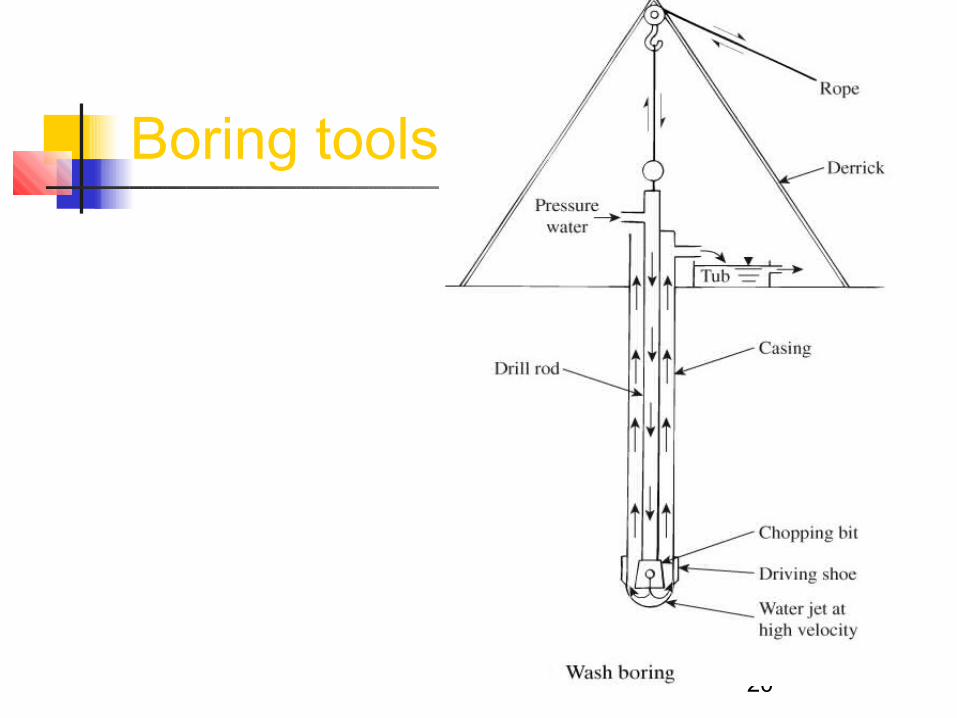
Boring tools Auger boring Power drills
20
Boring tools

21
Boring tools

22
Boring tools
23
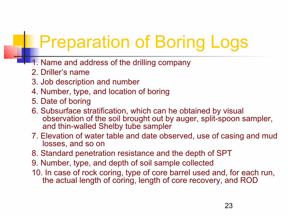
Preparation of Boring Logs1. Name and address of the drilling company2. Driller’s name3. Job description and number4. Number, type, and location of boring5. Date of boring6. Subsurface stratification, which can he obtained by visual
observation of the soil brought out by auger, split-spoon sampler, and thin-walled Shelby tube sampler
7. Elevation of water table and date observed, use of casing and mud losses, and so on
8. Standard penetration resistance and the depth of SPT9. Number, type, and depth of soil sample collected10. In case of rock coring, type of core barrel used and, for each run,
the actual length of coring, length of core recovery, and ROD

24

25
SOIL SAMPLING Two types of soil samples can be obtained during
sampling disturbed and undisturbed. The most important engineering properties required for foundation design are strength, compressibility, and permeability. Reasonably good estimates of these properties for cohesive soils can be made by laboratory tests on undisturbed samples which can be obtained with moderate difficulty. It is nearly impossible to obtain a truly undisturbed sample of soil; so in general usage the term "undisturbed" means a sample where some precautions have been taken to minimize disturbance or remolding effects. In this context, the quality of an "undisturbed" sample varies widely between soil laboratories.

26
Disturbed vs UndisturbedGood quality samples necessary.
AR<10%AR<10%
sampling tube
soil(%) 100
..
....2
22
×−=DI
DIDOAR
area ratioarea ratio
Thicker the wall, greater the disturbance.

27
Disturbed vs Undisturbed

28
Common Sampling Methods

29
ROCK SAMPLING
Rock cores are necessary if the soundness of the rock is to be established.
small cores tend to break up inside the drill barrel.
Larger cores also have a tendency to break up (rotate inside the barrel and degrade), especially if the rock is soft or fissured.

30
Rock coring

31
ROCK SAMPLING - Definition
32
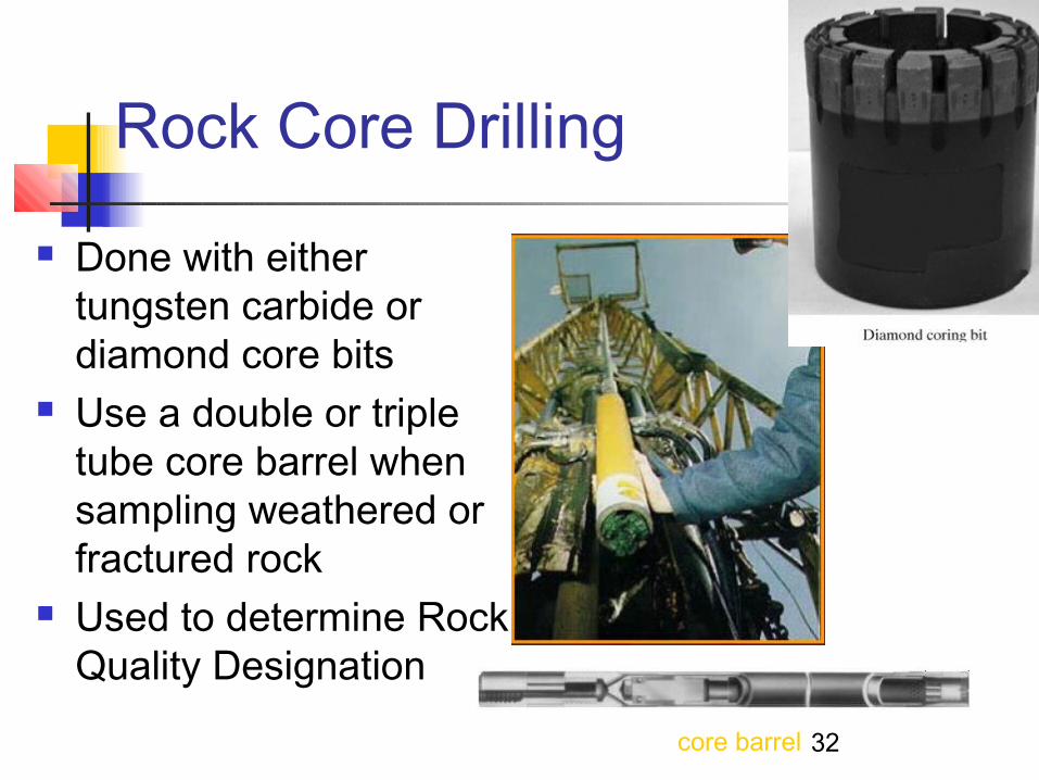
Rock Core Drilling
Done with either tungsten carbide or diamond core bits
Use a double or triple tube core barrel when sampling weathered or fractured rock
Used to determine Rock Quality Designation
core barrel

33
Rock Quality Designation RQD
34
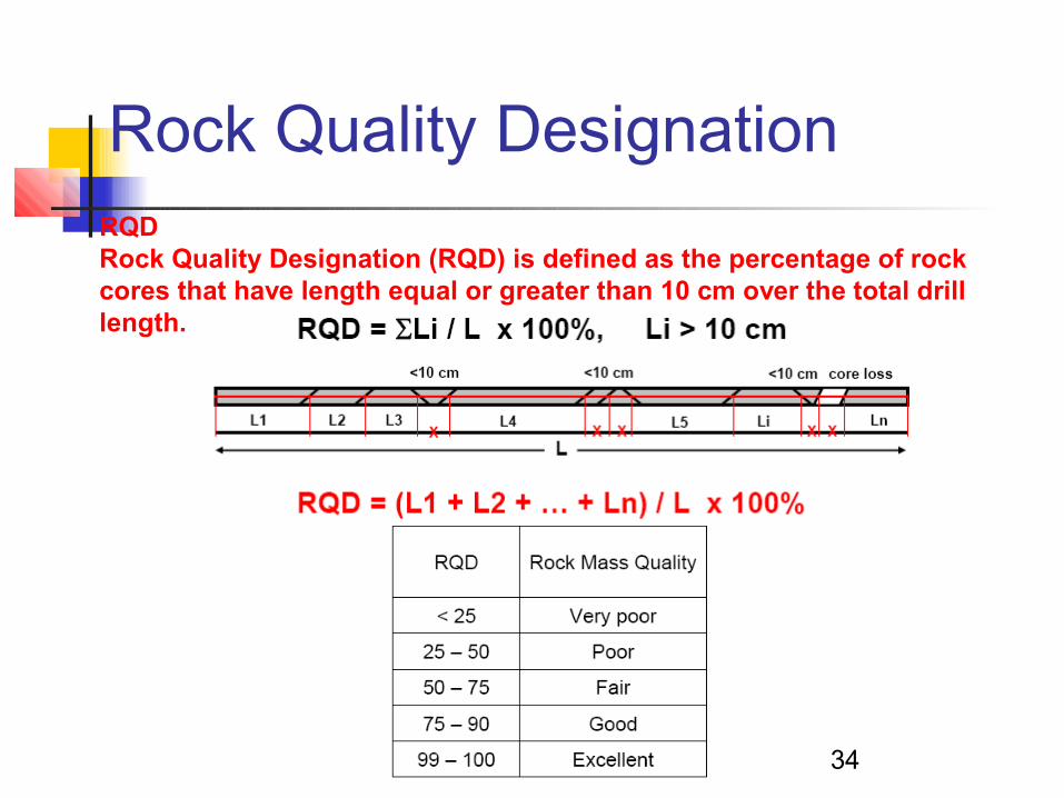
Rock Quality DesignationRQDRock Quality Designation (RQD) is defined as the percentage of rock cores that have length equal or greater than 10 cm over the total drill length.
35
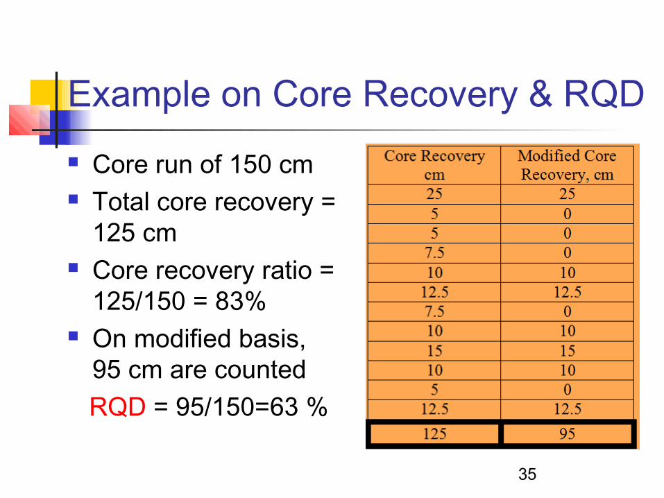
Example on Core Recovery & RQD Core run of 150 cm Total core recovery =
125 cm Core recovery ratio =
125/150 = 83% On modified basis,
95 cm are counted RQD = 95/150=63 %

36
GROUND WATER TABLE LEVEL Groundwater conditions and the potential for
groundwater seepage are fundamental factors in virtually all geotechnical analyses and design studies. Accordingly, the evaluation of groundwater conditions is a basic element of almost all geotechnical investigation programs. Groundwater investigations are of two types as follows:
Determination of groundwater levels and pressures.
Measurement of the permeability of the subsurface materials.
37
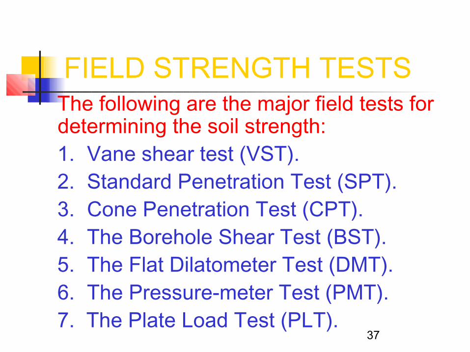
FIELD STRENGTH TESTS The following are the major field tests for
determining the soil strength: 1. Vane shear test (VST). 2. Standard Penetration Test (SPT). 3. Cone Penetration Test (CPT). 4. The Borehole Shear Test (BST). 5. The Flat Dilatometer Test (DMT). 6. The Pressure-meter Test (PMT). 7. The Plate Load Test (PLT).

38
FIELD STRENGTH TESTS

39
Standard Penetration Test (SPT)

40
Standard Penetration Test (SPT)

41
Standard Penetration Test (SPT) Corrections are normally applied to the SPT
blow count to account for differences in: • energy imparted during the test (60% hammer efficiency) • the stress level at the test depth The following equation is used to compensate
for the testing factors (Skempton, 1986):

42
Standard Penetration Test (SPT)

43
Standard Penetration Test (SPT)

44
Cone Penetration Test (CPT)
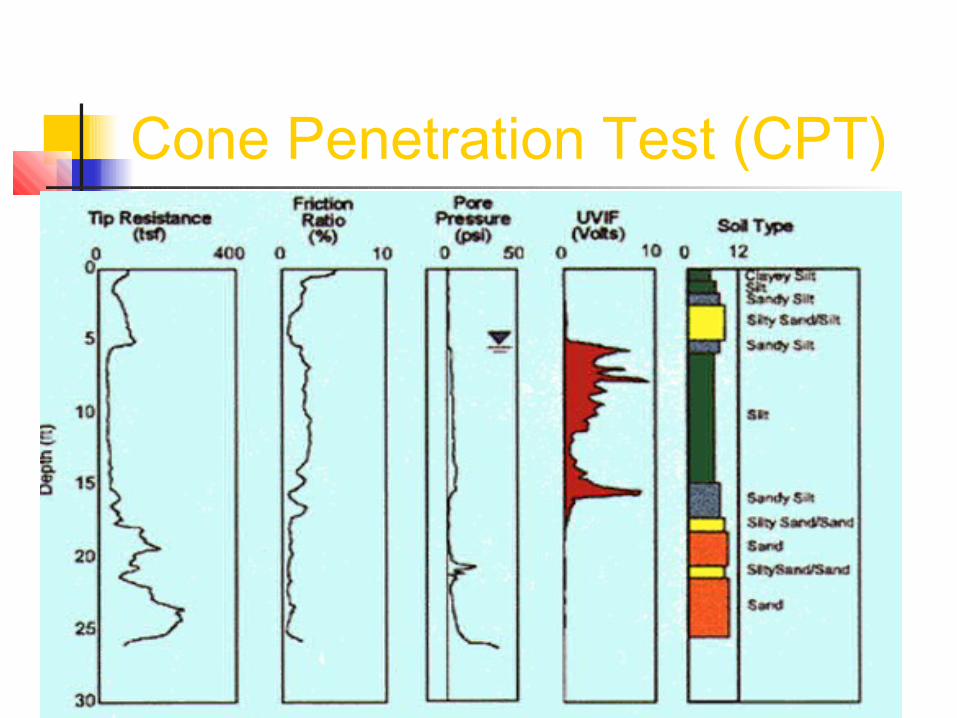
45
Cone Penetration Test (CPT)
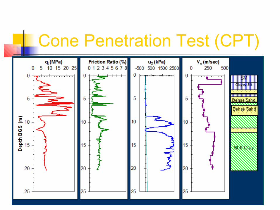
46
Cone Penetration Test (CPT)

47
Cone Penetration Test (CPT)

48
Cone Penetration Test (CPT)
49
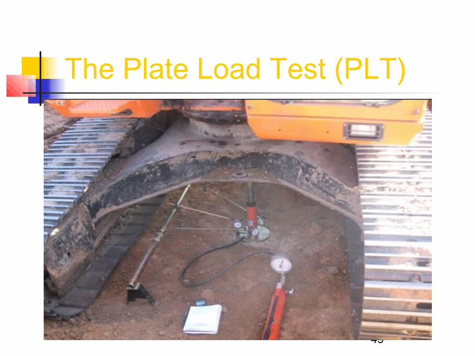
The Plate Load Test (PLT)
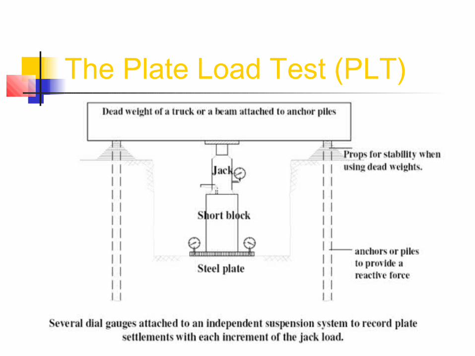
50
The Plate Load Test (PLT)

51
The Plate Load Test (PLT)

52
The Plate Load Test (PLT)Scale Effect in Foundation Design

53
Geotechnical Design Reports At the end of all subsoil exploration programs, the soil
and/or rock specimens collected from the field are subjected to visual observation and appropriate laboratory testing. After the compilation of all of the required information, a soil exploration report is prepared for the use of the design office and for reference during future construction work. Although the details and sequence of information in the report may vary to some degree is depending on the structure under consideration and the person compiling the report.
54
Subsoil Exploration Report 1. A description of the scope of the investigation2. A description of the proposed structure for which the subsoil exploration has
been conducted3. A description of the location of the site, including any structures nearby,
drainage conditions, the nature of vegetation on the site and surrounding it, and any other features unique to the site
4. A description of the geological setting of the site5. Details of the field exploration—that is, number of borings, depths of borings,
types of borings involved, and so on6. A general description of the subsoil conditions, as determined from soil
specimens and from related laboratory tests, standard penetration resistance and cone penetration resistance, and soon
7. A description of the water-table conditions8. Re commendations regarding the foundation, including the type of
foundation recommended, the allowable hearing pressure, and any special construction procedure that may he needed; alternative foundation design procedures should also be discussed in this portion of the report
9. Conclusions and limitations of the investigations

55
Subsoil Exploration ReportThe following graphical presentations should he
attached to the report:1. A site location map2. A plan view of the location of the borings with
respect to the proposed structures and those nearby
3. Boring logs4. Laboratory test results5. Other special graphical presentations

56
Example Table of Contents for a Geotechnical Investigation (Data) Report