Preface, Contents System Overview 1 Hardware Description and Commissioning 2 Function Description 3 Overview of System Integration 4 Centrally in SIMATIC S7–300 5 Distributed Link to SIMATIC S7/C7/PCS 7 6 Serial Link 7 Description of the Data Records 8 Optional Components 9 SIWATOOL - Description and Use 10 Error Diagnostics and Treatment 11 Technical Specifications 12 Sales/Hotline/Repairs/ Replacement Parts/Training/ Internet 13 Index Release 06/2005 Weighing Electronics Equipment Manual SIWAREX M
SIMATIC� and SIWAREX� are registered trademarks of SIEMENS AG.
This manual contains notices which you should observe to ensure your own personal safety,as well as to protect the product and connected equipment. These notices are highlighted inthe manual by a warning triangle and are marked as follows according to the level of danger:
!Danger
indicates that death, severe personal injury or substantial property damage will result if properprecautions are not taken.
!Warning
indicates that death, severe personal injury or substantial property damage can result if properprecautions are not taken.
!Caution
indicates that minor personal injury or property damage can result if proper precautions are nottaken.
Caution
No warning triangle means that property damage may occur if proper precautions are not taken.
Notice
NOTICE used without the safety alert symbol indicates a potential situation which, if notavoided, may result in an undesireable result or state.
Only qualified personnel should be allowed to install and work on this equipment. Quali-fied persons are defined as persons who are authorized to commission, to ground, and to tagcircuits, equipment, and systems in accordance with established safety practices and stan-dards.
Note the following:
!Warning
This device and its components may only be used for the applications described in the catalogor the technical description, and only in connection with devices or components from othermanufacturers which have been approved or recommended by Siemens.
This product can only function correctly and safely if it is transported, stored, set up, andinstalled correctly, and operated and maintained as recommended.
We have checked the contents of this manual for agreement with the hard-ware and software described. Since deviations cannot be precluded en-tirely, we cannot guarantee full agreement. However, the data in this ma-nual are reviewed regularly and any necessary corrections included insubsequent editions. Suggestions for improvement are welcomed.
Technical data subject to change.
����������� ��������
The reproduction, transmission or use of this document or its contents is notpermitted without express written authority. Offenders will be liable fordamages. All rights, including rights created by patent grant or registrationof a utility model or design, are reserved.
Editor: A&D SE ES4Publisher: A&D PI 14
� Siemens AG 2005 All rights reserved
Safety Guidelines
Qualified Personnel
Correct Usage
iSIWAREX M Equipment Manual(4) J31069-D0609-U001-A4-7618
Preface
This manual is part of the documentation for the SIWAREX M weighing mo-dule.
Users will find all information needed to handle the SIWAREX M.
Installation and commissioning personnel will find all information neededto install and commission the SIWAREX M.
The complete documentation package includes the following manuals.
1-1SIWAREX M Equipment Manual(4) J31069-D0609-U001-A4-7618
System Overview
This section gives you an overview of the functions of the SIWAREX Mweighing module and a description of its integration into the system.
1
1-2SIWAREX M Equipment Manual
(4) J31069-D0609-U001-A4-7618
1.1 Introduction
The SIWAREX M is a weighing module appropriate for verification. It per-mits complete integration of weighing and proportioning functions in theSIMATIC.
The basic system is the SIMATIC S7-300.
Since the SIWAREX M can be expanded as desired using standard componentsfrom the SIMATIC, SIMATIC HMI and SIMATIC NET series it provides youwith an optimal hardware and software environment in which to implementcustomized solutions.
The SIWAREX M handles the execution of weighing functions and the time-critical control of proportioning elements for proportioning scales within acomplete weighing system. The SIWAREX M can also be connected decen-trally to a SIMATIC PCS 7 via the ET 200M modular I/Osystem.
Figure 1-1 SIWAREX M with the SIMATIC S7-300
Just what is theSIWAREX M?
Standardcomponents
System Overview
1-3SIWAREX M Equipment Manual(4) J31069-D0609-U001-A4-7618
The SIWAREX M handles the execution of all weighing functions in a pro-cessing application.
Time-critical control of proportioning elements for proportioning scales is alsohandled directly by the SIWAREX M. Since the SIWAREX M is not depen-dent on the cycle time of the programmable controller, proportioning valvescan be shut off precisely to achieve an optimum in proportioning precision.
The SIWAREX M can be used for applications under obligation of verification(commercial scales) as well as for potentially explosive areas (i.e., zones 1 and2). An optional Ex-i interface ensures intrinsically safe supply of power to theload cells.
Additional features:
� S7-300 standard construction, connection technology and design
� Fill level and single-component proportioning scales with EC qualificationapproval for applications under obligation of verification (class III, 6000 d,commercial scales)
� High degree of measuring precision (0.01%) with a measuring value reso-lution of up to +524,000 parts
� CE, UL, CSA, FM and ISO 9001 certification
� Use in the S7-300 (direct integration as FM)
� Connection to SIMATIC S7/PCS 7 via ET 200M modular I/O systems
� 2 serial interfaces for connection of a verifiable printer, a verifiablememory and a verifiable remote display/PC or host
� 4 digital outputs, 3 digital inputs, 1 analog output
� Choice of parameterization methods:
– “SIWATOOL” parameter assignment software on PC underMS-WINDOWS; direct transmission to the RS 232 interface of theSIWAREX M
– Data block presetting entry in STEP 5/7; transmission of the data blockfrom the S7 CPU to SIWAREX M
� Load cell interface
– Short circuit and overload-proof power supply of the load cell (max. of180 mA)
– Detection of wire breaks on sensor, supply and measuring lines
– Load cell adjustment via software
– Intrinsically safe power supply of the load cell (option)
� SIWAREX M can be replaced without having to adjust the scales again.
� Operator control and monitoring via SIMATIC HMI
� Data buffering during power failure
� Write protection for adjustment data via calibration switch
What can theSIWAREX M do?
System Overview
1-4SIWAREX M Equipment Manual
(4) J31069-D0609-U001-A4-7618
Integration of the SIWAREX M into the SIMATIC provides a freely program-mable weighing system with which even complex tasks (e.g., multi-componentscales and multi-scale systems) can be implemented easily.
The SIWAREX M is snapped directly onto the SIMATIC S7 bus as a functionmodule. This direct integration of the SIWAREX M into the SIMATIC S7-300permits optimal utilization of all functions of the SIMATIC S7-300 program-mable controller.
Hardware and software flexibility permits the implementation of a wide varietyof applications (e.g., in the chemicals industry and foodstuffs industry). Thecomplete family of SIMATIC S7-300 modules is available as the hardwareplatform. Easy operator control and monitoring is available e.g. with theSIMATIC HMI operator panels.
PS: Power supplyCPU: SIMATIC S7 CPUCP: Communications processorOP: Operator panel
PS
Figure 1-2 SIWAREX M in the SIMATIC S7-300
Starting with CPU 314, a multiple-line setup can be used with the SIMATICS7-300. The multiple-line setup requires the IM 360/IM 361 or IM 365 (start-ing with version 2) interface modules.
The IM 621 interface can be used to connect SIWAREX M to the SIMATICC7-621. The IM 361 interface is used to connect SIWAREX M to theSIMATIC C7-623/624/626. IM 360 has already been integrated in theSIMATIC C7-623/624/626.
System integrationof the SIWAREX Minto the SIMATIC
Central integration into the S7-300
Multiple-linesetup with theSIMATIC S7
Multiple-linesetup with theSIMATIC C7
System Overview
1-5SIWAREX M Equipment Manual(4) J31069-D0609-U001-A4-7618
Since the SIWAREX M can be connected to the PROFIBUS-DP via the ET 200M modular I/O system (IM 153-1 or IM 153-2 interface), the SIWAREX M can be linked as distributed periphery to the SIMATIC S7-300,SIMATIC S7-400, SIMATIC S7-400H, SIMATIC C7 or SIMATIC PCS 7.
Transmission distances of up to 23 km are permitted. The IM 153-2 is onlynecessary when required by other modules (e.g., FM 353).
Maximum number of SIWAREX M units per IM 153-1 or IM 153-2 interface
– For distributed connection to SIMATIC S7 � Max. of 7 SIWAREX Ms(Exception: Max. of 8 SIWAREX Ms with CPU 318-2 DP,
CPU 417-4 DP, IM 467 and CPU 443-5 Ext.)
– With active backplane bus � Max. of 4 SIWAREX Ms
PS: Power supplyIM: IM 153-1 or IM 153-2DO: Digital output moduleDI: Digital input module
PS
Figure 1-3 The SIWAREX M as distributed periphery in the SIMATIC S7
When the SIWAREX M is connected decentrally to a SIMATIC S7-300/400,SIMATIC C7 or SIMATIC PCS 7, an CPU with PROFIBUS-DP interface, aCP 443-5 (from version 2) or an IM 467 for connection to PROFIBUS is requi-red. The version (status 4/99) of the CP 342-5 cannot be used for the bus con-nection.
Distributedintegrationin the S7/C7
System Overview
1-6SIWAREX M Equipment Manual
(4) J31069-D0609-U001-A4-7618
While the SIWAREX M is usually integrated in SIMATIC S7 programmablecontrollers with the typical PLC programming languages STL (statement list),LAD (ladder diagram) or FBD (function block diagram), integration in theSIMATIC PCS 7 process control system is performed via graphic configura-tion in the CFC (continuous function chart). In other words, integration isstructured instead of programmed.
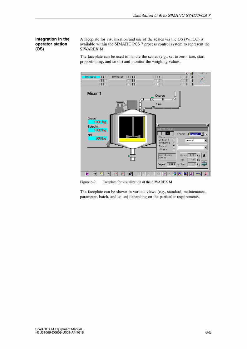
The SIWAREX M modules are represented in the engineering system (ES)with technology blocks in the CFC chart. In contrast, the SIWAREX M mod-ules are represented on the operator station (OS) as faceplates (i.e., screenblocks).
The faceplates can be used to monitor the weight values and control theSIWAREX M modules.
A separate configuration package is available for the SIMATIC PCS 7 processcontrol system which contains a block for the CFC chart, a faceplate for the OSand the documentation.
Figure 1-4 Representation of the SIWAREX M in the ES engineering system (left)and on the OS operator station (right)
Distributed in-tegration inSIMATIC PCS 7
System Overview
1-7SIWAREX M Equipment Manual(4) J31069-D0609-U001-A4-7618
The many functions of the SIWAREX M (e.g., an analog output for analogindicators or process recorders, DI/DO for weighing functions, and serial inter-faces for printer and remote display with operator control) also permit it to beused as a field device independent of the controller.
Figure 1-5 The SIWAREX M as a controller-independent field device
In addition to the bus interface for the SIMATIC and two serial interfaces(TTY and RS 232C), the SIWAREX M is equipped with 4 digital outputs,3 digital inputs and 1 analog output.
The functions to be handled by the inputs and outputs can be specified byparameterization as required by your specific applications.
Using STEP 7 or SIWATOOL (a WINDOWS parameter assignment program),you can optimize parameter specifications for weighing applications.
Printer/host/PC/PLC/verifiable memory
CPUSIMATICS7-300
PROFIBUS-DPinterface(IM 153-1or IM 153-2)
SIMATIC S7bus
RS 232C TTY Meas. val.acquisition
Load cellsupply
3 digitalinputs
1 analogoutput
4 digitaloutputs
Host/remote display/PLC
SIWAREX M
EX-iinterface(option)
Junction box
LCTarePrintSet to zeroStart proportioning:Choiceof 20functions
CoarseFineOverfillLimit value:Choice of 30functions
Analog displayControllerMotor controlProcess recorder:::
LC LC LC
Figure 1-6 Diagram of the SIWAREX M setup
Integration of theSIWAREX M inde-pendent of thecontroller
Periphery
System Overview
1-8SIWAREX M Equipment Manual
(4) J31069-D0609-U001-A4-7618
1.2 Setup and Components of a Weighing Machine
A complete industrial weighing machine (scales) consists of the following pri-mary components.
Junctionbox
ÍÍÍÍÍÍÍÍÍÍ
Load
Connection cable
ÉÉÉÉÉÉÉÉÉÉLoad cell Load cell
Foundation
Load bearing element
SIWAREX Mmodule Operator
control +monitoringDisplays and operator panelsPrinteretc.
Figure 1-7 Setup of the weighing system with a SIWAREX M
Load bearing implements are used to hold the load to be weighed. Examplesinclude platforms, hoppers, trolleys, containers and so on.
Load cells are measuring sensors which convert a physical value (i.e., weight)into a proportionate electrical signal.
Built-in elements ensure that the load cells function correctly. Built-in andguide elements prevent faulty loading which can cause measuring errors anddamage to the load cells. Faulty loading is caused by forces (e.g., lateralforces) for which the direction of action of the load cell springs is not designed.
The junction box is used to add together the load cell signals from several loadcells switched in parallel.
The SIWAREX M module is used as an electronic evaluation device whichacquires and further evaluates the signal coming from the load cell.
Load bearingimplement
Load cell
Built-in elements
Junction box
SIWAREX M
System Overview
1-9SIWAREX M Equipment Manual(4) J31069-D0609-U001-A4-7618
1.3 Weighing Functions
SIWAREX M offers the following functions.
� Setting to zero
� Taring
� Automatic zero point offset
� Scales standstill message
� Limit values (min/max/empty/overfilled)
� Proportioning valve control (coarse/fine)
� Tolerance monitoring of the proportioning process
� Automatic reproportioning
� Automatic proportioning optimization (switchoff value “fine”)
� Proportioning monitoring (monitoring of material flow and time)
� Inching mode
These functions support fill level scales, single-component scales, and multi-component scales.
1.4 Fill Level Scales
Fill level scales are used to acquire the fill level of hoppers, tanks and othercontainers. The SIWAREX M offers weighing functions such as gross/netweight calculation, setting to zero, taring, limit value monitoring, scales stand-still check and printing. These basic weighing functions can also be used toimplement other types of scales such as platform scales, crane scales, vehiclescales, etc.
Fill level scales
System Overview
1-10SIWAREX M Equipment Manual
(4) J31069-D0609-U001-A4-7618
1.5 Single-Component Scales
The SIWAREX M provides the functions required by single-component scales.These functions include coarse/fine flow proportioning, tolerance check andfinished message. Material feed is controlled for fill weighing. Special sup-plementary functions (e.g., automatic reproportioning when tolerances are un-derranged, inching mode, and automatic correction of the fine flow switchoffvalue) are also included in the module.
In principle, the functions of a single-component weighing machine for deduc-tion weighing are the same as those for fill weighing. The only difference isthat material removal is controlled and not material addition (sign reversal fornet weight calculation).
S7–300
Filling
Coarse Fine
LC LC
Junction box
SIEMENS
SIMATIC
S7–300
CPU 314 DI DI DO CPSIWAREX M
JB
Figure 1-8 Single-component scales
Single-componentscales for fillweighing
Single-componentscales for deduc-tion weighing
System Overview
1-11SIWAREX M Equipment Manual(4) J31069-D0609-U001-A4-7618
1.6 Multi-Component Scales
Multi-component scales are used to make mixtures based on preset recipes andcan be set up from standard components (e.g., SIWAREX M, SIMATIC digitalinput/output modules, and so on).
The SIWAREX M handles the function of a multiplexed single-componentweighing system within a multi-component weighing system (i.e., during pro-portioning, the SIWAREX M performs the setpoint-actual value comparisonand controls proportioning independently of the cycle time of the automationsystem. The coarse and fine flow signal on the digital outputs of theSIWAREX M is available for controlling the proportioning devices. Two digi-tal outputs are sufficient since, with a multiple-component weighing system,these are switched through to the applicable bin (see figure) via the root of afloating digital output module of the SIMATIC (e.g., relay module). This per-mits almost any number of supply bins to be addressed.
Note
If the nominal current (0.5 A) and the total current (1 A) of the digital outputsof the SIWAREX M are not exceeded, a SIMATIC relay output module can beused to switch through the coarse and fine flow signals to the individual bins.If the nominal current or the total current is exceeded, a coupling relay mustbe used in addition to the SIMATIC relay output module.
Recipe sequence control on the CPU or a host control system gives theSIWAREX M the material-related proportioning data (e.g., setpoint, coarse andfine flow switch-off value, tolerance limits, and so on) for each individualcomponent.
Figure 1-9 Multi-component scales based on SIWAREX M + SIMATIC
Principle offunction
System Overview
1-12SIWAREX M Equipment Manual
(4) J31069-D0609-U001-A4-7618
Depending on the components to be proportioned (e.g., component 1), a digitaloutput module of the SIMATIC now switches through the signal path of thecoarse and fine flow signal to bin 1. The scales are then tared, and proportion-ing is started. After conclusion of proportioning, the process is repeated for allother components.
Depending on the requirements, various standard packages are available forimplementation of multi-component scales (e.g., Batch flexible for high-endperformance range or SIWAREX Batch for low-end and medium performancerange).
The SIWAREX Batch option package supports use of the SIWAREX M asproportioning scales. It can be run on programmable controllers SIMATICS7-300 and SIMATIC S7-400. A configuration on ProTool which can beadapted to the specific application is standardly made available for operatorcontrol and monitoring with SIMATIC HMI operator panel OP27. Using anopen interface, other operator panels (e.g., OP37) or the WinCC visualizationsystem can also be integrated.
Since SIWAREX Batch can be scaled, it can be adapted to the particular re-quirements. The number of production lines and scales in the system can bedefined by the user as well as the numbers of recipes and components.
The SIWAREX Batch software package contains all necessary standard func-tions which are required regardless of sector. SIWAREX Batch is designed sothat application-specific expansions and supplements can be easily added viadefined interfaces which are open for the user (e.g., accepting recipes from ahost control system).
SIWAREX Batch consists of a kernel for batch control and several subpro-grams for functions such as weighing, mixing, emptying and so on.
SIWAREX Batch can be used for several production lines at the same time.This permits proportioning procedures to be run simultaneously on severalscales.
Standard packagesfor multi-compo-nent scales
Recipe controlwith SIWAREXBatch(optional package)
System Overview
1-13SIWAREX M Equipment Manual(4) J31069-D0609-U001-A4-7618
1.7 Scales for Potentially Explosive Areas
Connection of load cells located in potentially explosive areas requires an in-termediate box (type SIWAREX IS) which is circuited between theSIWAREX weighing module and the load cell (special model for the Ex area)or the junction box (JB).
Since the intermediate box contains an Ex-i interface, it must be located out-side the potentially explosive area.
Appropriate SIMATIC modules are available for digital or analog inputs/out-puts in the potentially explosive area.
Ex modules are used in the automation of chemical plants and are suitable forapplications in measuring, and open-loop and closed-loop control technology.The primary task of the Ex modules is to separate the intrinsically safe electri-cal circuits of the potentially explosive area and the non-intrinsically safe, in-ternal electrical circuits of the programmable controller.
If the digital inputs/outputs of the SIWAREX M are to be installed in the Exarea, conventional explosion-proof circuit breakers (24 V) can be used.
Remote displays with an analog interface can be used, for example, as remotedisplays for the Ex area. These remote displays are connected via an explo-sion-proof circuit breaker to the analog output of the SIWAREX M or via anintrinsically safe analog output of the SIMATIC. Another choice is to usepressure encapsulated remote displays.
Special intrinsically safe operator panels are available from various manufac-turers for use in the potentially explosive areas of zones 1 and 2. These opera-tor panels can be connected to the SIMATIC S7 via the MPI interface of the S7CPU or via an additive communications processor (CP), for example.
Pressure encapsulated operator panels (SIMATIC HMI) can also be usedinstead of intrinsically safe devices.
Scales for poten-tially explosiveareas, zones 1and 2
1-15SIWAREX M Equipment Manual(4) J31069-D0609-U001-A4-7618
1.8 Other Types of Scales
By using standard components of the SIMATIC, SIMATIC HMI and SIMATICNET series, other types of scales can also be implemented. A few examplesare listed below.
� Counting scales
� Check weighers
� Vehicle scales
� Filling scales
� Conveyor belt scales
� Loss in weight scales
Other types of scales
System Overview
1-16SIWAREX M Equipment Manual
(4) J31069-D0609-U001-A4-7618
System Overview
2-1SIWAREX M Equipment Manual(4) J31069-D0609-U001-A4-7618
Hardware Description and Commissioning
This section contains all information required for commissioning. Subjectsinclude mounting, connection, assignment of parameters, and a description ofthe interfaces and indicator and setting elements.
Adherence to these safety notes is mandatory. Non-compliance will invali-date your warranty.
!Warning
Persons who are not qualified should not be allowed to handle this equip-ment/system. Non-compliance with warnings appearing on the equipmentitself or on the system cabinet can result in severe personal injury or substan-tial property damage. Only qualified personnel should be allowed to workon this equipment/system.
Note
This product has been developed, manufactured, tested and documented inaccordance with relevant safety standards. Under normal conditions, thisproduct will not be a source of danger to property or life.
!Caution
Commissioning is prohibited until it has been determined that the machine inwhich these components are to be installed meets the requirements of the89/392/EC guidelines.
General safetynotes
2
2-2SIWAREX M Equipment Manual
(4) J31069-D0609-U001-A4-7618
!Warning
The following rules must be complied with to ensure that the requirementscontained in EU guidelines 89/336/EC are complied with.
� The setup guidelines and safety notes in the applicable manuals and sup-plementary documentation must be adhered to for both the automationsystem and the SIWAREX M.
� All signal lines to the SIWAREX M must be shielded and applied to agrounded shield retainer rail (see section 2.2).
� Sub D plug connectors with shield braiding and plug connector hoodwith shielding must be used.
Hardware Description and Commissioning
2-3SIWAREX M Equipment Manual(4) J31069-D0609-U001-A4-7618
2.1 Installing the SIWAREX M
Before beginning actual, physical installation, relevant safety precautionsmust be taken and the following points adhered to or clarified.
� Was the module still in its original packaging ?
� Check the shipment for transportation damages.
� Check the shipment for completeness.
The S7 interface of the SIWAREX M corresponds to the I/O bus (P bus) ofthe SIMATIC S7-300.
All slots of the SIMATIC S7-300 which can be used by function modules(FM) can also be used for the SIWAREX M.
For additional information, see the SIMATIC S7-300 manual.
The maximum number of SIWAREX M modules which can be installed inthe SIMATIC depends on the following factors.
� Maximum number of modules in the central/expansion rack (CR/ER) ormodular ET 200M I/O device
� Storage requirements on the S7-/C7-CPU
� Maximum permissible current consumption (5 V) from the S7 backplanebus
A quadruple DIP switch on the back of the housing is used as the calibrationswitch, and to switch off the BASP/OD function.
The settings on this DIP switch must be performed before installing theSIWAREX M since the switch can no longer be accessed after installation.
!Warning
If the BASP function is switched off, you must provide other suitable mea-sures to prevent outputs which are not switched off from endangering peopleor systems.
If the BASP function is not switched off, the digital and analog outputs arereset and a running proportioning procedure is stopped when the BASP signalis output by the SIMATIC CPU. See also chapter 3.18.
Cutout forDIP switch
1
OFF ON
4
3
2
1
Figure 2-1 Back of the SIWAREX M
Setting elements
Hardware Description and Commissioning
2-5SIWAREX M Equipment Manual(4) J31069-D0609-U001-A4-7618
Table 2-1 Setting functions of the DIP switch
Switch Description Status on Delivery
1) Switch must be set to OFF (service function). OFF
2) Download function
– OFF = Operation mode
– ON = Download mode (only for service purposes)
OFF
3) BASP/OD function:
Use in S7-300 or ET 200M:
– OFF=BASP/OD active
– ON=BASP/OD inactive
Use without SIMATIC:
– Always ON
OFF
4) Switch activates write protection (only required for verified scales)Standard setting: OFF (i.e., write protection deactivated)
OFF
Hardware Description and Commissioning
2-6SIWAREX M Equipment Manual
(4) J31069-D0609-U001-A4-7618
2.1.2 Mounting the Module on the Rail
Note
It is imperative to adhere to EMC guidelines when installing the cables (alsothose outside cabinets).
Do not place cables next to energy-technology cables, and shield the cablesas described.
In most cases, two-sided shield application is recommended. However, ifinterference is primarily low-frequency, one-sided shield application may bemore effective.
Adhere to the grounding concept of the SIMATIC S7-300 to avoid problemswith the potential.
The setup guidelines of the SIMATIC S7 (see manual of the S7-300 pro-grammable controller under setup and CPU data) must be adhered to for allmounting steps, and the following instructions must be performed in the or-der shown below.
A setup which does not conform to EMC guidelines will reduce measuringaccuracy and, in extreme situations, cause ”internal error 04” or ”externalerror 02.”
1. Switch off all voltages on the SIMATIC S7, ensure that it cannot beswitched back on again, and mark accordingly.
2. Make or check protective conductor connection. (See setup guidelines.)
3. Mount shield connecting element.
– The shield connecting element must be mounted on the rail directlyunder the slot in which the SIWAREX M is installed.
– Each cable to be connected to the SIWAREX M requires a shield ter-minal on the shield rail of the shield connecting element (see section2.2).
4. Insert bus connector. (See setup guidelines.)
– A bus connector is supplied with each SIWAREX M. The bus connec-tor must be inserted first on the module installed in the slot to the leftof the SIWAREX M.
5. Hang SIWAREX M. (See setup guidelines.)
6. Screw down SIWAREX M. (See setup guidelines.)
7. Label SIWAREX M. (See setup guidelines.)
Mounting steps
Hardware Description and Commissioning
2-7SIWAREX M Equipment Manual(4) J31069-D0609-U001-A4-7618
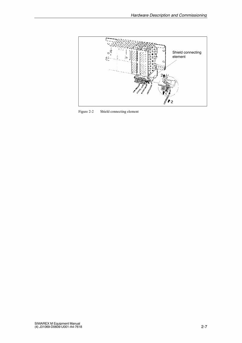
Shield connectingelement
Figure 2-2 Shield connecting element
Hardware Description and Commissioning
2-8SIWAREX M Equipment Manual
(4) J31069-D0609-U001-A4-7618
2.2 Connection and Wiring
Since the rules for wiring listed in the table below apply to SIMATIC S7-300modules, they must also be used for the wiring of front connector X1 on theSIWAREX M.
Table 2-2 Rules for wiring
ÁÁÁÁÁÁÁÁÁÁÁÁÁÁ
Rule forÁÁÁÁÁÁÁÁÁÁ
Flexible LineÁÁÁÁÁÁÁÁÁÁÁÁÁÁÁÁÁÁÁÁÁÁÁÁ
Flexible Line with Core End SleevesÁÁÁÁÁÁÁÁÁÁÁÁÁÁÁÁÁÁÁÁÁ
Max. line cross sec-tion
ÁÁÁÁÁÁÁÁÁÁÁÁÁÁÁ
0.25 to 1.5 mm2ÁÁÁÁÁÁÁÁÁÁÁÁÁÁÁÁÁÁÁÁÁÁÁÁÁÁÁÁÁÁÁÁÁÁÁÁ
0.25 to 1.5 mm2
ÁÁÁÁÁÁÁÁÁÁÁÁÁÁÁÁÁÁÁÁÁ
Number per connec-tion
ÁÁÁÁÁÁÁÁÁÁÁÁÁÁÁ
1 ÁÁÁÁÁÁÁÁÁÁÁÁÁÁÁÁÁÁÁÁÁÁÁÁÁÁÁÁÁÁÁÁÁÁÁÁ
Max. of 2 (in one end sleeve)
ÁÁÁÁÁÁÁÁÁÁÁÁÁÁ
Stripping length ÁÁÁÁÁÁÁÁÁÁ
6 mm ÁÁÁÁÁÁÁÁÁÁÁÁÁÁÁÁÁÁÁÁÁÁÁÁ
6 mm
ÁÁÁÁÁÁÁÁÁÁÁÁÁÁÁÁÁÁÁÁÁ
Core end sleeves ÁÁÁÁÁÁÁÁÁÁÁÁÁÁÁ
- ÁÁÁÁÁÁÁÁÁÁÁÁÁÁÁÁÁÁÁÁÁÁÁÁÁÁÁÁÁÁÁÁÁÁÁÁ
Without insulation collar (short) DIN 46228
ÁÁÁÁÁÁÁÁÁÁÁÁÁÁ
Turning moment ÁÁÁÁÁÁÁÁÁÁ
60-80 Ncm ÁÁÁÁÁÁÁÁÁÁÁÁÁÁÁÁÁÁÁÁÁÁÁÁ
60-80 Ncm
Non-flexible lines may not be used.
Select the shield terminal size appropriate to the cable diameter.
Securing a cable with the shield terminal requires that approximately 1.5 cmof the cable insulation be cut away at the appropriate location so that theshield is bared.
1
2 Shield terminal
Shield rail(fixed)
Figure 2-3 Mounting the shield terminals
!Caution
Make sure that you do not damage the shield braiding when stripping thecable.
When applying shields to all cables connected to the SIWAREX M, makesure that there is enough cable between the shield connecting element andthe SIWAREX M so that the SIWAREX M can be removed with all itscables still connected.
Rules for wiring
Shield terminals
Hardware Description and Commissioning
2-9SIWAREX M Equipment Manual(4) J31069-D0609-U001-A4-7618
The following figure shows all available indication and connection elementson the front of the SIWAREX M.
1
9
1
15
X2
X3
7
8
9
11
13 I_OUT+
14 I_OUT–
15 SENSE+
16 SENSE–
17 SIG+
18 SIG–
19 EXC+
20 EXC–
1 L+
2 M
12 DI_M
SF
ADJ
0
OF
DO1
DO2
DO3
24V
DO4
DC24V
6
5
4 DO_M
3 DO_L+
DI1
DI3
X1
DI_L+
DI2 10
Power supply
Digital outputs
Digital inputs
Analog output
Load cells
Figure 2-4 Connection elements on the front of the SIWAREX M
Table 2-3 Indication elements on the front of the SIWAREX M
ÁÁÁÁÁÁÁÁÁÁÁÁ
Label ÁÁÁÁÁÁÁÁÁÁÁÁ
LED Color ÁÁÁÁÁÁÁÁÁÁÁÁÁÁ
Position ÁÁÁÁÁÁÁÁÁÁÁÁ
Explanation
ÁÁÁÁÁÁÁÁÁÁÁÁ
SF ÁÁÁÁÁÁÁÁÁÁÁÁ
Red ÁÁÁÁÁÁÁÁÁÁÁÁÁÁ
LED 1 (to the left) ÁÁÁÁÁÁÁÁÁÁÁÁ
System fault
ÁÁÁÁÁÁÁÁÁÁÁÁ
OF ÁÁÁÁÁÁÁÁÁÁÁÁ
Red ÁÁÁÁÁÁÁÁÁÁÁÁÁÁ
LED 2 (to the left) ÁÁÁÁÁÁÁÁÁÁÁÁ
Operation fault
ÁÁÁÁÁÁÁÁÁÁÁÁ
Green ÁÁÁÁÁÁÁÁÁÁÁÁÁÁ
LED 3 (to the left) ÁÁÁÁÁÁÁÁÁÁÁÁ
Scales calibrated
ÁÁÁÁÁÁÁÁÁÁÁÁ
�� ÁÁÁÁÁÁÁÁÁÁÁÁ
Green ÁÁÁÁÁÁÁÁÁÁÁÁÁÁ
LED 4 (to the left) ÁÁÁÁÁÁÁÁÁÁÁÁ
Standstill
ÁÁÁÁÁÁÁÁÁÁÁÁ
� 0� ÁÁÁÁÁÁÁÁÁÁÁÁ
Green ÁÁÁÁÁÁÁÁÁÁÁÁÁÁ
LED 5 (to the left) ÁÁÁÁÁÁÁÁÁÁÁÁ
1/4d zero
ÁÁÁÁÁÁÁÁÁÁÁÁ
ADJ ÁÁÁÁÁÁÁÁÁÁÁÁ
Green ÁÁÁÁÁÁÁÁÁÁÁÁÁÁ
LED 6 (to the left) ÁÁÁÁÁÁÁÁÁÁÁÁ
Scales adjusted
ÁÁÁÁÁÁÁÁÁÁÁÁ
24 V ÁÁÁÁÁÁÁÁÁÁÁÁ
Green ÁÁÁÁÁÁÁÁÁÁÁÁÁÁ
LED 1 (to the right)ÁÁÁÁÁÁÁÁÁÁÁÁ
Power supply
Located on the right side of the housing are additional status lamps whichindicate the status of the DI/DOs. The LEDs are permanently assigned to therespective input/output.
Indication andconnection ele-ments
Indication elements
Hardware Description and Commissioning
2-10SIWAREX M Equipment Manual
(4) J31069-D0609-U001-A4-7618
2.2.1 Front Plug Connector (X1)
You can label the individual connections of the front plug connector with alabel strip which is included. This provides customized identification of yourinput and output assignments.
The SIWAREX M module requires 24 V direct current.
The 24 V must be turned on and off at the same time the 24 V for the SI-MATIC CPU or ET 200 is turned on and off.
The maximum current consumption is 300 mA.
The lines are connected in front plug connector X1 on screw contacts 1 and 2(see figure 2-4).
The X1 front connector is equipped with 20 screw contacts for wiring thefollowing connections.
� Power supply
� Load cells
� Digital inputs/outputs
� Analog output
The required cable cross sections can be found in this section.
Disconnect the front connector from the module to make connection workeasier.
Labelling
Power supply
Front connector
Hardware Description and Commissioning
2-11SIWAREX M Equipment Manual(4) J31069-D0609-U001-A4-7618
2.2.2 Load Cells (X1)
In principle, all measured value sensors (i.e., load sensors) can be connectedto the SIWAREX M provided they meet the following requirements.
� Characteristic value up to 4 mV/V
� Supply voltage 10.2 V
� Measuring procedure based on the Wheatstone bridge
Table 2-4 Allocation of the load cell connection
ÁÁÁÁÁÁÁÁÁÁÁÁ
Screw TerminalÁÁÁÁÁÁÁÁÁÁÁÁ
Load Cell ÁÁÁÁÁÁÁÁÁÁÁÁÁÁ
Signal ÁÁÁÁÁÁÁÁÁÁÁÁ
Meaning
ÁÁÁÁÁÁÁÁÁÁÁÁ
X1.15 ÁÁÁÁÁÁÁÁÁÁÁÁ
UF + ÁÁÁÁÁÁÁÁÁÁÁÁÁÁ
SENSE + ÁÁÁÁÁÁÁÁÁÁÁÁ
Sensor line +
ÁÁÁÁÁÁÁÁÁÁÁÁ
X1.16 ÁÁÁÁÁÁÁÁÁÁÁÁ
UF - ÁÁÁÁÁÁÁÁÁÁÁÁÁÁ
SENSE - ÁÁÁÁÁÁÁÁÁÁÁÁ
Sensor line -
ÁÁÁÁÁÁÁÁÁÁÁÁ
X1.17 ÁÁÁÁÁÁÁÁÁÁÁÁ
UM + ÁÁÁÁÁÁÁÁÁÁÁÁÁÁ
SIG + ÁÁÁÁÁÁÁÁÁÁÁÁ
Meas. voltage +
ÁÁÁÁÁÁÁÁÁÁÁÁ
X1.18 ÁÁÁÁÁÁÁÁÁÁÁÁ
UM - ÁÁÁÁÁÁÁÁÁÁÁÁÁÁ
SIG - ÁÁÁÁÁÁÁÁÁÁÁÁ
Meas. voltage -ÁÁÁÁÁÁÁÁÁÁÁÁ
X1.19ÁÁÁÁÁÁÁÁÁÁÁÁ
US +ÁÁÁÁÁÁÁÁÁÁÁÁÁÁ
EXC +ÁÁÁÁÁÁÁÁÁÁÁÁ
Supply voltage +ÁÁÁÁÁÁÁÁÁÁÁÁ
X1.20ÁÁÁÁÁÁÁÁÁÁÁÁ
US -ÁÁÁÁÁÁÁÁÁÁÁÁÁÁ
EXC -ÁÁÁÁÁÁÁÁÁÁÁÁ
Supply voltage -
Load cells must be connected in accordance with the following rules.
1. A junction box must be used under the following conditions.
– More than one load cell is connected. (Remember that the load cellsmust then be switched in parallel.)
– The distance between load cell and SIWAREX M is greater than thelongest available length of load cell connection cable.
2. When there is a danger of equipotential bonding currents from the cableshield, an equipotential bonding conductor must be installed parallel tothe load cell cable, or the shield terminal in the junction box must be usedto apply the shield. (Under normal conditions, the shield is applied to thecable leadin supports of the junction box.)
3. Twisted core pairs should be used for the lines specified below.
– (+) and (-) sensor line
– (+) and (-) measuring voltage line
– (+) and (-) supply voltage line
4. The shield on the SIWAREX M must be applied to the shield holder ele-ment.
The “SIWAREX IS” Ex-i interface (see section 9.4) is required when loadcells are to be operated in potentially explosive areas.
Load cells whichcan be connected
Connection alloca-tion on front con-nector X1
Load cell connec-tion for normalareas (standard)
Load cell connec-tion for potentiallyexplosive areas
Hardware Description and Commissioning
2-12SIWAREX M Equipment Manual
(4) J31069-D0609-U001-A4-7618
A
B
Shield
191517181620
SIWAREX M
X1
Junction box
Load cells
Shield connecting element
Max. of1000 m
EXC+SENSE+
SIG+SIG–
SENSE–EXC–
SUPPLY +
SIGNAL +
SENSE +
SIGNAL –
SENSE –
SUPPLY –
1)2)
3)
4)
5)
6)
1) PLUS-INPUT2) PLUS-SENSE3) PLUS-OUTPUT
4) MINUS-OUTPUT5) MINUS-SENSE6) MINUS-INPUT
Soldering tag
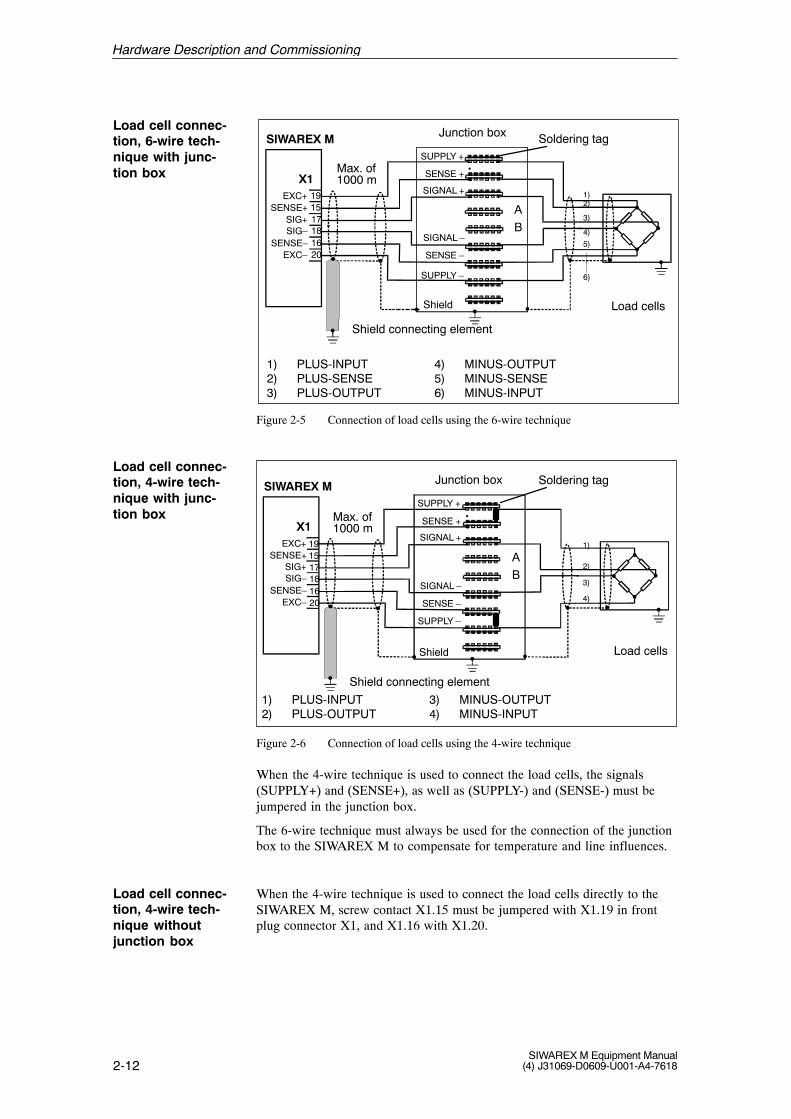
Figure 2-5 Connection of load cells using the 6-wire technique
A
B
Shield
191517181620
SIWAREX M
X1
Junction box
Max. of1000 m
Load cells
EXC+SENSE+
SIG+SIG–
SENSE–EXC–
SUPPLY +
SIGNAL +
SENSE +
SIGNAL –
SENSE –
SUPPLY –
2)
3)
4)
1)
1) PLUS-INPUT2) PLUS-OUTPUT
3) MINUS-OUTPUT4) MINUS-INPUT
Shield connecting element
Soldering tag
Figure 2-6 Connection of load cells using the 4-wire technique
When the 4-wire technique is used to connect the load cells, the signals(SUPPLY+) and (SENSE+), as well as (SUPPLY-) and (SENSE-) must bejumpered in the junction box.
The 6-wire technique must always be used for the connection of the junctionbox to the SIWAREX M to compensate for temperature and line influences.
When the 4-wire technique is used to connect the load cells directly to theSIWAREX M, screw contact X1.15 must be jumpered with X1.19 in frontplug connector X1, and X1.16 with X1.20.
Load cell connec-tion, 6-wire tech-nique with junc-tion box
Load cell connec-tion, 4-wire tech-nique with junc-tion box
2-13SIWAREX M Equipment Manual(4) J31069-D0609-U001-A4-7618
The cable of each load cell is led through the cable leadin supports (PGscrew-type connection). The cable shield must be applied to the PG screw-type connection.
The individual cores of the load cell cable are circuited in parallel to the re-spective soldering tags (i.e., SUPPLY, SENSE and SIGNAL).
� Solder all feeder voltage lines (+) of the load cells and the weighing elec-tronics to soldering tag ”SUPPLY +”.
� Solder all feeder voltage lines (-) of the load cells and the weighing elec-tronics to soldering tag ”SUPPLY -”.
� Use the same procedure on the remaining lines.
Soldering tags A and B are reserve connection elements (e.g., for installationof precision resistors for the cut-off load calibration). A cut-off load calibra-tion is usually only performed for scales on which cut-off loads occur (e.g.,vehicle scales).
Parallel circuitingof load cells in thejunction box
Hardware Description and Commissioning
2-14SIWAREX M Equipment Manual
(4) J31069-D0609-U001-A4-7618
2.2.3 Digital Outputs (X1)
The SIWAREX M is equipped with four, floating digital outputs (DO) with anominal voltage of +24 V and an output current of up to 0.5 A per output.
The four digital outputs are potentially bound with each other. They have acommon ground and a 24 V voltage supply with fuse. The digital outputs areshort circuit-proof and overload-proof.
The status of the digital outputs is indicated via LEDs on the front of theSIWAREX M.
When inductive consumers are connected, the digital output used must beequipped with a freewheeling diode.
The digital outputs can be assigned as desired to the 30 weighing functionsavailable.
!Warning
The 24 V power supply (terminal X1.3) may not be turned on until the assignment of the DO is known and the current signal status will not be ahazard to the system.
The four digital outputs are located on screw contacts 5 to 8 in front plugconnector X1.
Screw contacts 3 and 4 provide the 24 V power supply (L+/M) for all fourdigital outputs.
3 4 5 6 7 8
SIWAREX M 24 V power supply
Load
DO_L+
DO_MDO 1DO 2DO 3DO 4
X1
Max. of 1000 m
Figure 2-7 Digital outputs
Description
Connection
Hardware Description and Commissioning
2-15SIWAREX M Equipment Manual(4) J31069-D0609-U001-A4-7618
Table 2-5 Assignment of the digital outputs (X1)
ÁÁÁÁÁÁÁÁÁÁÁÁÁÁÁÁÁÁÁÁÁÁ
Screw Terminal ÁÁÁÁÁÁÁÁÁÁÁÁÁÁÁÁÁÁÁÁÁÁÁÁ
Signal
ÁÁÁÁÁÁÁÁÁÁÁÁÁÁÁÁÁÁÁÁÁÁ
X1.3 ÁÁÁÁÁÁÁÁÁÁÁÁÁÁÁÁÁÁÁÁÁÁÁÁ
DO_L+
ÁÁÁÁÁÁÁÁÁÁÁÁÁÁÁÁÁÁÁÁÁÁ
X1.4 ÁÁÁÁÁÁÁÁÁÁÁÁÁÁÁÁÁÁÁÁÁÁÁÁ
DO_M
ÁÁÁÁÁÁÁÁÁÁÁÁÁÁÁÁÁÁÁÁÁÁ
X1.5 ÁÁÁÁÁÁÁÁÁÁÁÁÁÁÁÁÁÁÁÁÁÁÁÁ
DO1
ÁÁÁÁÁÁÁÁÁÁÁÁÁÁÁÁÁÁÁÁÁÁ
X1.6 ÁÁÁÁÁÁÁÁÁÁÁÁÁÁÁÁÁÁÁÁÁÁÁÁ
DO2
ÁÁÁÁÁÁÁÁÁÁÁÁÁÁÁÁÁÁÁÁÁÁ
X1.7 ÁÁÁÁÁÁÁÁÁÁÁÁÁÁÁÁÁÁÁÁÁÁÁÁ
DO3
ÁÁÁÁÁÁÁÁÁÁÁÁÁÁÁÁÁÁÁÁÁÁ
X1.8 ÁÁÁÁÁÁÁÁÁÁÁÁÁÁÁÁÁÁÁÁÁÁÁÁ
DO4
Assignment
Hardware Description and Commissioning
2-16SIWAREX M Equipment Manual
(4) J31069-D0609-U001-A4-7618
2.2.4 Digital Inputs (X1)
The SIWAREX M is equipped with three, floating digital 24 V inputs (DI).
The three digital inputs are potentially bound with each other. They have acommon reference point (M).
The digital inputs can be assigned as desired to the 20 weighing commandsavailable.
The status of the digital inputs is indicated via LEDs on the front of theSIWAREX M.
!Warning
The inputs may not be activated until the assignment of the DI is known andactivation will not be a hazard to the system.
The three digital inputs are located on screw contacts 9 to 11 in front plugconnector X1.
The common reference point (M) of all three digital inputs is screw con-tact 12.
9
10
DI 1
11
12
DI 2
DI 3DI_M
SIWAREX M
X1 24 VMax. of 1000 m
Figure 2-8 Digital inputs
Table 2-6 Assignment of the digital inputsÁÁÁÁÁÁÁÁÁÁÁÁÁÁÁÁÁÁÁÁÁÁScrew Terminal
2-17SIWAREX M Equipment Manual(4) J31069-D0609-U001-A4-7618
2.2.5 Analog Output (X1)
The SIWAREX M is equipped with an analog output for outputting an analogvalue (e.g., for an analog display, a process recorder or a controller). Theanalog output is designed as a 0/4 to 20 mA current output. The analog out-put can be used to output the gross or net weight, or an externally prespeci-fied value from the SIMATIC or from a host.
The output analog value can be supplied to measured value displays whichare not under obligation of verification, process recorders or controllers, forexample.
!Warning
Before a new SIWAREX M is used, the parameter assignment of the analogoutput must be checked!
The analog output is located on screw contacts 13 and 14 in front plug con-nector X1. The output can be operated with either 0 to 20 mA or with 4 to 20 mA.
13
14
I_OUT +I_OUT –
2
SIWAREX M
x1Max. of 200 m
Example: LIYCY 1 x 2 x 0.5 mm
Load< 600 Ohm(incl. line resistance)
Figure 2-9 Example of the connection of the analog output
Table 2-7 Assignment of the analog output
ÁÁÁÁÁÁÁÁÁÁÁÁÁÁÁÁÁÁÁÁÁÁ
Screw Contact ÁÁÁÁÁÁÁÁÁÁÁÁÁÁÁÁÁÁÁÁÁÁÁÁ
SignalÁÁÁÁÁÁÁÁÁÁÁÁÁÁÁÁÁÁÁÁÁÁ
X1.13 ÁÁÁÁÁÁÁÁÁÁÁÁÁÁÁÁÁÁÁÁÁÁÁÁ
Current output + (I_OUT+)ÁÁÁÁÁÁÁÁÁÁÁÁÁÁÁÁÁÁÁÁÁÁ
X1.14 ÁÁÁÁÁÁÁÁÁÁÁÁÁÁÁÁÁÁÁÁÁÁÁÁ
Current output - (I_OUT-)
Description
Connection
Assignment
Hardware Description and Commissioning
2-18SIWAREX M Equipment Manual
(4) J31069-D0609-U001-A4-7618
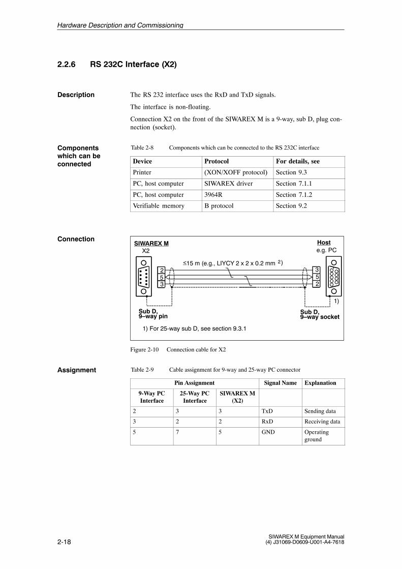
2.2.6 RS 232C Interface (X2)
The RS 232 interface uses the RxD and TxD signals.
The interface is non-floating.
Connection X2 on the front of the SIWAREX M is a 9-way, sub D, plug con-nection (socket).
Table 2-8 Components which can be connected to the RS 232C interface
Device Protocol For details, see
Printer (XON/XOFF protocol) Section 9.3
PC, host computer SIWAREX driver Section 7.1.1
PC, host computer 3964R Section 7.1.2
Verifiable memory B protocol Section 9.2
253 2
53
SIWAREX M Hoste.g. PCX2
15 m (e.g., LIYCY 2 x 2 x 0.2 mm< 2)
Sub D,9–way pin
Sub D,9–way socket
1) For 25-way sub D, see section 9.3.1
1)
Figure 2-10 Connection cable for X2
Table 2-9 Cable assignment for 9-way and 25-way PC connector
ÁÁÁÁÁÁÁÁÁÁÁÁÁÁÁÁÁÁÁÁÁÁÁÁÁÁ
Pin Assignment ÁÁÁÁÁÁÁÁÁÁÁÁ
Signal Name ÁÁÁÁÁÁÁÁÁÁ
Explanation
ÁÁÁÁÁÁÁÁÁÁÁÁÁÁÁ
9-Way PCInterface
ÁÁÁÁÁÁÁÁÁÁÁÁÁÁÁ
25-Way PCInterface
ÁÁÁÁÁÁÁÁÁÁÁÁÁÁÁ
SIWAREX M(X2)ÁÁÁÁÁÁÁÁÁÁÁÁÁÁÁÁÁÁ
ÁÁÁÁÁÁÁÁÁÁÁÁÁÁÁÁÁÁÁÁ
ÁÁÁÁÁ2 ÁÁÁÁÁ
ÁÁÁÁÁ3 ÁÁÁÁÁ
ÁÁÁÁÁ3 ÁÁÁÁÁÁ
ÁÁÁÁÁÁTxD ÁÁÁÁÁ
ÁÁÁÁÁSending data
ÁÁÁÁÁÁÁÁÁÁ
3 ÁÁÁÁÁÁÁÁÁÁ
2 ÁÁÁÁÁÁÁÁÁÁ
2 ÁÁÁÁÁÁÁÁÁÁÁÁ
RxD ÁÁÁÁÁÁÁÁÁÁ
Receiving data
ÁÁÁÁÁÁÁÁÁÁ
5 ÁÁÁÁÁÁÁÁÁÁ
7 ÁÁÁÁÁÁÁÁÁÁ
5 ÁÁÁÁÁÁÁÁÁÁÁÁ
GND ÁÁÁÁÁÁÁÁÁÁ
Operatingground
Description
Componentswhich can beconnected
Connection
Assignment
Hardware Description and Commissioning
2-19SIWAREX M Equipment Manual(4) J31069-D0609-U001-A4-7618
2.2.7 TTY Interface (X3)
The TTY interface uses the RxD and TxD signals, and can be operated ineither passive (floating) or active (non-floating) mode.
Jumpers in the plug connector of the connection cable are used to switchbetween passive and active modes.
The connection element is a 15-way, sub D, plug connector (socket) with ascrew lock.
Table 2-10 Components which can be connected to the TTY interface
Device Protocol For details, see
Remote digital display 4-digit display5-digit display6-digit display
Section 9.1
PC, host computer SIWAREX driver Section 7.1.1
PC, host computer 3964R Section 7.1.2
For detailed information on the connection of the remote displays, see chap-ters 9.1 and 9.2.
Table 2-11 Assignment of X3 (TTY interface of the SIWAREX M)
After the module has been mounted and all connections have been set up, apartial function test of the SIWAREX M and all connected components mustbe performed at this stage of the commissioning procedure.
Perform the individual steps of the partial test in the order specified below.
Check to determine whether you have performed all steps up to now cor-rectly.
� Is the exterior of the module undamaged ?
� Is the module installed in the correct slot ?
� Have all mounting screws been tightened correctly ?
� Have all connection cables been connected correctly and secured ?
� Has the front plug connector been plugged in correctly ?
� Have all shields been applied to the shield holder element ?
� Have you removed all tools, materials and parts not belonging to the S7or the SIWAREX M from the mounting rail and the modules ?
Caution
The 24 V power supply for the SIMATIC S7–CPU or ET 200M and the SIWAREX M must be turned on and off at the same time.
Introduction
Visual inspection
Hardware Description and Commissioning
2-21SIWAREX M Equipment Manual(4) J31069-D0609-U001-A4-7618
After the power is turned on, the SIWAREX M switches to operation mode.If operating correctly, the LEDs below will indicate the following states.
LED (24 V) � ON status
LED (SF) � OFF status
LED (OF) � OFF status
If the LEDs do not indicate the correct states, proceed as described in section 11.
9
1 L+S F
OF
24V DC24VX1
Figure 2-11 Location of the LEDs to be checked
LED test on the SIWAREX M
Hardware Description and Commissioning
2-22SIWAREX M Equipment Manual
(4) J31069-D0609-U001-A4-7618
2.4 Assigning Parameters
Depending on your system configuration, there are various ways to assignparameters and commission the SIWAREX M.
Use the overview below to select the best method of parameter assignmentand commissioning for your special system configuration.
S7–300SIWAREX M
S7-300 backplane bus
PROFIBUS-DP
RS 485 TTYRS 232
X3X2
MPI bus
Prin
ting
form
at
TP
FC
STEP 7DB editor
PG HostPC/PG
SIWATOOLParameter
Com
mis
sion
ing
on u
ser
softw
are
Dep
ende
nt
CPU
IM 153-1
telegram
for para. assign.
Par
amet
er a
ssig
nmen
t
Com
mis
sion
ing
Par
amet
er a
ssig
nmen
t
Prin
ting
form
atC
omm
issi
onin
g
Par
amet
er a
ssig
nmen
t
Prin
ting
form
at
HostPC/PG
SIWATOOLParametertelegram
for para. assign.
Com
mis
sion
ing
Par
amet
er a
ssig
nmen
t
Prin
ting
form
atC
omm
issi
onin
g
Par
amet
er a
ssig
nmen
t
or IM 153-2
Figure 2-12 Methods of parameter assignment for various system configurations
Introduction
Overview of possi-ble parameter as-signments andcommissioning
Hardware Description and Commissioning
2-23SIWAREX M Equipment Manual(4) J31069-D0609-U001-A4-7618
Via PG with DB editor
Edit data block with the editor in the SIMATIC S7, and transfer with theFC SIWA-M function to the SIWAREX M.
(Parameter assignment and commissioning are possible.)
Edit the I/O bar of the SIWAREX block in the CFC chart, and then transferthe modified data to the SIWAREX M.(Commissioning with SIWATOOL)
Via PC/PG with SIWATOOL
Install SIWATOOL on the PC/PG.
SIWATOOL uses pull-down menus and runs under WINDOWS.
(Parameter assignment, commissioning and printing formatting are possible.)
Via host with data telegram
Data telegrams are used to perform parameter assignment, commissioningand printing formatting.
Link to theSIMATIC S7
Link to theSIMATIC PCS 7
Link to a PC with SIWATOOL
Link tothe host
Hardware Description and Commissioning
2-24SIWAREX M Equipment Manual
(4) J31069-D0609-U001-A4-7618
2.5 Preparation and Certification of Scales Subject to Verification
Notice
Adhere to the latest qualification approval of SIWAREX.
Preparations prior to actual certification by the office of weights and mea-sures must be performed by the operator in accordance with followinginstructions.
� Commission the SIWAREX M.
� Adjust the scales as described in the manual.
� Check all relevant points for compliance with (1) and (2) or (3) below.
(1) = ER (90/384/EC) European guidelines on non-automatic scales
(2) = EN 45 501 European standards for non-automatic scales
(3) = National guidelines for automatic scales
Fill in the appropriate data on the verification label for the remote display.
� Max. = maximum load; example: max. = 3 t or 3,000 kg
� Min. = 20 e (in accordance with EN 45 501, class III commercial scales)A maximum resolution of 6,000 e (digit intervals) is possible for opera-tion with verification capability.Example: 20 e = 3,000 kg/6,000 x 20 = 10 kg
� e = verification value (in accordance with EN 45 501) Example: 3,000 kg/6,000 = 0.5 kg
� s = serial number of the name plate of the SIWAREX M
Affixing the verification label depends on the remote display being used.
For additional information, see the documentation of your remote display.
� Certification of the verified scales is performed by an official of theweights and measures office.
� After certification, turn off the SIWAREX M.
� Remove the SIWAREX M from the rail so that the DIP switch on theback of the SIWAREX M can be accessed.
Activate write protection via the DIP switch. (See section 2.1.1.)
DIP switch 4 to position “ON”
Preparation
Verification label
Certification of the SIWAREX M
Write protection
Hardware Description and Commissioning
2-25SIWAREX M Equipment Manual(4) J31069-D0609-U001-A4-7618
After activation of write protection, the official of the weights and measuresoffice will affix the inspection seal and verification stamp.
ÉÉÉÉÉÉÉÉ
ÉÉÉÉÉÉÉÉ
ÉÉÉÉÉÉÉÉ
ÉÉÉÉÉÉÉÉ
1
DIP switch
SIW
AR
EX
M
SIE
ME
NS
7MH
4553 - 1AA
41
LB/jm
/nnnnsss
Made in G
ermany
E-S
tand: 01
951PS
0
DI2DI3DO1DO2DO3DO4
24V
1 2
3 4
Weighing SystemSFOF
ADJ
SIWAREX
3
4
1
2
View of Back View of Side
View of Front
Affixing an inspection sealover the DIP switch on theback of the SIWAREX M
Affixing an inspection sealover the area where the twohalves of the housing arejoined
Affixing of three inspectionseals on the front of theSIWAREX M
Affixing the verification stamp(M) on the front of theSIWAREX M
1
2
3
4
Figure 2-13 Placement of the inspection seal and verification stamp
Inspection seal onthe SIWAREX M
Hardware Description and Commissioning
2-26SIWAREX M Equipment Manual
(4) J31069-D0609-U001-A4-7618
A successful final check concludes certification of the SIWAREX M.
� Turn on the SIWAREX M.
� The LED (scales verified) on the front of the SIWAREX M mustlight up.
� The verified scales are now certified and ready for operation.
Final check
Hardware Description and Commissioning
3-1SIWAREX M Equipment Manual(4) J31069-D0609-U001-A4-7618
Function Description
The SIWAREX M can be integrated in SIMATIC S7-300 programmable con-trollers and can also be used as distributed periphery in the ET 200M. TheSIWAREX M can also communicate with other host systems via the serialinterfaces.
Independent of the cycle time of the host system, the SIWAREX M handlesexecution of the basic weighing functions and the time-critical control ofproportioning elements for proportioning scales within a complete weighingsystem.
The SIWAREX M can be used in applications requiring verification certifica-tion and also in potentially explosive areas.
SIWAREX M offers the following functions.
� Zero setting and taring the scales
� Automatic zero point offset
� Scales standstill message
� Limit value generation (minimum/maximum/empty/overfilled)
� Proportioning valve control (coarse/fine)
� Tolerance monitoring of the proportioning process
� Automatic reproportioning
� Automatic proportioning optimization
� Inching mode
� Proportioning monitoring (material flow and time monitoring)
Introduction
Overview
3
3-2SIWAREX M Equipment Manual
(4) J31069-D0609-U001-A4-7618
3.1 A/D Conversion (Measured Value Acquisition)
The analog/digital converter of the SIWAREX M converts the analog mea-suring signal of the load cells into a digital signal.
Every 20 msec a measured value is determined with a �524,000-part resolu-tion.
Since the SIWAREX M has been pre-calibrated at the factory, the module canbe exchanged without having to adjust the scales again. A test weight can beused to adjust the SIWAREX M, or a theoretical adjustment can be per-formed using the characteristic value and nominal load of the load cell.
Notice
Theoretical adjustment cannot be used for applications requiring certifica-tion.
Table 3-1 Data word for A/D conversion
Function SIMATIC Data Record Format Comments
S7/C7
Structure NameAddr No Byte Bit Length
Variable NameAddr. No. Byte Bit Length
(Byte)
Unfiltered raw valueDIGITS
346 33 0 8 DINT Unit = digitUnfiltered raw valueUNFILTERED
346 33 0 - 8 DINT Unit = digit
Description
Calibration
Function Description
3-3SIWAREX M Equipment Manual(4) J31069-D0609-U001-A4-7618
3.2 Digital Filtering
An adjustable digital filter compensates for interference caused by vibrationand load fluctuations, for example. This filter is particularly recommended ifyou are using worm drives, vibrating troughs and mixers.
350 33 4 8 DINT Unit = digitFiltered raw valueFILTERED
350 33 4 - 8 DINT Unit = digit
Illegal limit frequency digital filter Message via indication words of 101 0 2 3 BYTE Data error 01Illegal limit frequency digital filter Message via indication words ofthe applications
101 0-2 - 3 BYTE Data error 01
* Factory setting of SIWAREX M
Description
Filtering principle
Function Description
3-4SIWAREX M Equipment Manual
(4) J31069-D0609-U001-A4-7618
3.3 Weight Calculation and Adjustment
Weight calculation is used to convert raw measured values into standardized,gross weight values. The calculation is performed every 20 msec. In addi-tion, measured values with a higher resolution (by a factor of 10) are avail-able to the user for service purposes. This is very helpful for scales requiringverification since the resolution of their indicated values is limited. The re-quired standardization or adjustment factor is determined during adjustment.
The characteristic value entry specifies the measuring range set for the A/Dconverter. Possible entries are 1, 2 and 4 mV/V (i.e., three measuringranges).
The next greater characteristic value must be specified for the values whichare between 1, 2 or 4. In individual cases, it is also possible to specify asmaller characteristic value when the load cell(s) is (are) not utilized up totheir nominal load.
All input and output values related to weight refer to the same decimal place.This makes the internal calculations independent of the decimal place. Thedecimal place can be specified from 0 to 5. The decimal place is only re-levant for the display or printer. Remember that a total of 6 digit positions isavailable.
Adjustment is performed in 2 steps.
During the first step, the filtered raw value is stored (via “zero point valid”adjustment command) for the scales zero point in adjustment digit 0.
During the second step, the filtered raw value is stored (via “adjustmentweight valid” command) for the adjustment weight in adjustment digit 1.
Adjustment digits 0 and 1 are not indicated until adjustment has been com-pleted.
Weight calculation
Characteristicvalue
Decimal place
Adjustment
Function Description
3-5SIWAREX M Equipment Manual(4) J31069-D0609-U001-A4-7618
Note
When certain commands (i.e., “zero point valid”, “adjustment valid” or“load factory setting”) are called directly after each other, a waiting periodof 5 seconds must be maintained between calls. Otherwise the commandswill be rejected by the SIWAREX M.
A timeout prevents the maximum permissible number of write cycles for anEEPROM from being exceeded by an accidental cyclic call of these com-mands (see section 3.17).
When an attempt is made to call one of these three commands again withinthese 5 seconds, the command is rejected and the 5-second waiting period isretriggered again.
The minimum adjustment weight must be at least 5% of the measuring rangeset. This is checked by the SIWAREX M during the adjustment procedure ( 25000 digits). The maximum permissible indication increments (“d”) forverified operation is not checked (maximum load, digit increment).
The scales are adjusted by transferring plausible adjustment digit 1 (adjust-ment digit 1 greater than adjustment digit 0).
The unit of weight can be specified as any 2 ASCII characters. This unit ofweight is only used for the display and printer. The unit of weight is not usedfor internal calculations.
Weight
DIGITSFull scale524287
000000 Adjustment digit 1
Adjustment weight
Adjustedscales zeropoint
Dea
d lo
ad
Zer
o se
tting
are
a
Calibration diagonal
Load cellnot loaded
Adjustment digit 0
Figure 3-2 Adjustment procedure
During adjustment (step 2) in operation requiring verification, the minimumincrement voltage of 0.5 �V/e is monitored for a scale interval. The operat-ing mode can be set to “verification required” or “verification not required”.
Adjustment forverification capa-bility
Function Description
3-6SIWAREX M Equipment Manual
(4) J31069-D0609-U001-A4-7618
When the scales have already been adjusted, readjustment can be performedwith the “zero point valid” and/or “adjustment weight valid” command.
Note
When adjustment digits 0 and 1 contain the value 0, this indicates that theSIWAREX M has not been adjusted.
Readjustment
Function Description
3-7SIWAREX M Equipment Manual(4) J31069-D0609-U001-A4-7618
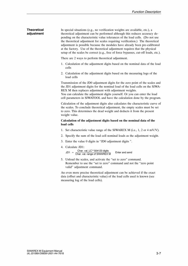
In special situations (e.g., no verification weights are available, etc.), atheoretical adjustment can be performed although this reduces accuracy de-pending on the characteristic value tolerances of the load cells. (Do not usethe theoretical adjustment for scales requiring verification.) The theoreticaladjustment is possible because the modules have already been pre-calibratedat the factory. Use of the theoretical adjustment requires that the physicalsetup of the scales be correct (e.g., free of force bypasses, cut-off loads, etc.).
There are 2 ways to perform theoretical adjustment.
1. Calculation of the adjustment digits based on the nominal data of the loadcells
2. Calculation of the adjustment digits based on the measuring logs of theload cells
Transmission of the JD0 adjustment digits for the zero point of the scales andthe JD1 adjustment digits for the nominal load of the load cells on the SIWA-REX M then replaces adjustment with adjustment weights. You can calculate the adjustment digits yourself. Or you can enter the loadcell parameters in SIWATOOL and have the calculation done by the program.
Calculation of the adjustment digits also calculates the characteristic curve ofthe scales. To conclude theoretical adjustment, the empty scales must be setto zero. This determines the dead weight and deducts it from the presentweight value.
Calculation of the adjustment digits based on the nominal data of theload cells
1. Set characteristic value range of the SIWAREX M (i.e., 1, 2 or 4 mV/V).
2. Specify the sum of the load cell nominal loads as the adjustment weight.
3. Enter the value 0 digits in “JD0 adjustment digits ”.
4. Calculate JD1:
JD1 �Char. val_LC * 504123 digits
Char. val. range of SIWAREX MEnter and send
5. Unload the scales, and activate the “set to zero” command.Remember to use the “set to zero” command and not the “zero pointvalid” adjustment command.
An even more precise theoretical adjustment can be achieved if the exactdata (offset and characteristic value) of the load cells used is known (seemeasuring log of the load cells).
Theoreticaladjustment
Function Description
3-8SIWAREX M Equipment Manual
(4) J31069-D0609-U001-A4-7618
Calculation of the adjustment digits based on the measuring logs of theload cells
1. Since the load cells have a nominal characteristic value of 2 mV/V, thecharacteristic value range 0 to 2 mV/V must be set for the SIWAREX M.
2. Specify and send the sum of the nominal load cell loads as the adjustmentweight.
3. Calculate JD0: JD0 �Offset_LC * 504123 digits
Char. val. range of SIWAREX M
4. Calculate JD1:
JD1 �Char. val._LC * 504123 digits
Char. val. range of SIWAREX M� JD0; Enter and send
5. Unload the scales and activate the “set to zero” command.Remember to use the “set to zero” command and not the “zero pointvalid” adjustment command.
Since there are no verification weights for 20-ton, pig iron scales, a theoreti-cal adjustment is to be performed. The following technical information canbe taken from the measuring logs for the 3 load cells used.
Characteristic Value Offset
Load cell 1 2.0511 mV/V +17.23 �V/V
Load cell 2 1.9998 mV/V -12.47 �V/V
Load cell 3 2.0245 mV/V -9.01 �V/V
Calculated mean values 2.0251 mV/V -1.42 �V/V
Calculation of the adjustment digits:
Adj. digit 0 �� 1.42 �V�V x 504123 digits
2 mV�V� � 358 digits
Adj. digit 1 �2.0251 mV�V x 504123 digits
2 mV�V� (� 358 digits) � 510091 digits
Example
Function Description
3-9SIWAREX M Equipment Manual(4) J31069-D0609-U001-A4-7618
Data Words, Commands and Messages
Table 3-3 Data words, commands and messages for adjustment
Function SIMATIC Data Record Format Comments
S7/C7
Structure NameAddr No Byte Bit Length
Variable NameAddr. No. Byte Bit Length
(Byte)
Decimal point
ADJ_DATA
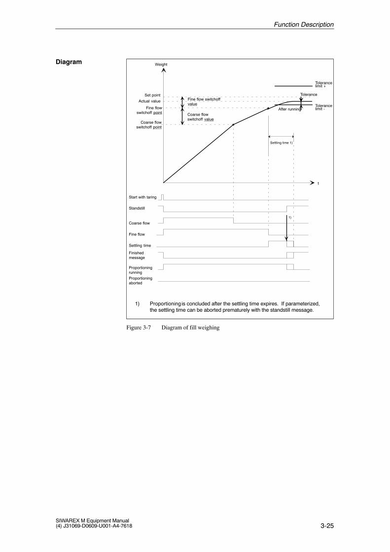
102 3 12 42 WORD
Selection code (dec.)0= xxxxxx *1= xxxxx.x2= xxxx xxDecimal point
338 32 0 8 DINTGross weight indicated more preciselyGROSS
338 32 0 - 8 DINT
Scales adjustedSTATUS
333 31 1 0 6 BOOL Status informationScales adjustedSCALE_ADJ
333 31 1 0 6 BOOL Status information
Adjustment weight too small Message via indication words of 101 0 2 3 BYTE Data error 02Adjustment weight too small Message via indication words ofthe applications
101 0-2 - 3 BYTE Data error 02
Min increment voltage too small Message via indication words of 101 0 2 3 BYTE Data error 03Min. increment voltage too small Message via indication words ofthe applications
101 0-2 - 3 BYTE Data error 03
Distance between adjustment points too small Message via indication words of 101 0 2 3 BYTE Data error 11Distance between adjustment points too small Message via indication words ofthe applications
101 0-2 - 3 BYTE Data error 11
Specified weight greater than permissible num- Message via indication words of 101 0 2 3 BYTE Data error 13Specified weight greater than permissible num-ber range
Message via indication words ofthe applications
101 0-2 - 3 BYTE Data error 13
Illegal decimal point Message via indication words of 101 0 2 3 BYTE Data error 14Illegal decimal point Message via indication words ofthe applications
101 0-2 - 3 BYTE Data error 14
Illegal characteristic value Message via indication words of 101 0 2 3 BYTE Data error 15Illegal characteristic value Message via indication words ofthe applications
101 0-2 - 3 BYTE Data error 15
Illegal digit increment Message via indication words of 101 0 2 3 BYTE Data error 16Illegal digit increment Message via indication words ofthe applications
101 0-2 - 3 BYTE Data error 16
Adjustment data not permitted since proportion- Message via indication words of 101 0 2 3 BYTE Handling error 01Adjustment data not permitted since proportion-ing procedure is running
Message via indication words ofthe applications
101 0-2 - 3 BYTE Handling error 01
Adjustment command cannot be executed since Message via indication words of 101 0 2 3 BYTE Handling error 02Adjustment command cannot be executed sinceproportioning procedure is running.
Message via indication words ofthe applications
101 0-2 - 3 BYTE Handling error 02
Function Description
3-10SIWAREX M Equipment Manual
(4) J31069-D0609-U001-A4-7618
Table 3-3 Data words, commands and messages for adjustment
CommentsFormatData RecordSIMATICFunction
S7/C7
Length(Byte)
BitByteNo.Addr.Structure Name Length
(Byte)BitByteNo.Addr.
Variable Name
Function not executed since scales are verified Message via indication words of 101 0 2 3 BYTE Handling error 07Function not executed since scales are verified Message via indication words ofthe applications
101 0-2 - 3 BYTE Handling error 07
Wait time of 5 seconds not adhered to Message via indication words of 101 0 2 3 BYTE Handling error 10Wait time of 5 seconds not adhered to Message via indication words ofthe applications
101 0-2 - 3 BYTE Handling error 10
Distance between adjustment points too small Message via indication words of 101 0 2 3 BYTE Handling error 22Distance between adjustment points too small Message via indication words ofthe applications
101 0-2 - 3 BYTE Handling error 22
* Factory setting of SIWAREX M
Function Description
3-11SIWAREX M Equipment Manual(4) J31069-D0609-U001-A4-7618
3.4 Digit Increment
The digit increment determines the increment width of the indication valuesgross, net and tare. Possible increments are 1, 2, 5, 10, 20 and 50. Thesevalues can be indicated with increased resolution (factor 10).
A resolution of up to 6000 e (e = verification value, digit increment) is possi-ble for operation subject to verification.
Table 3-4 Parameters and data for digit increment
Function SIMATIC Data Record Format Comments
S7/C7
Structure NameAddr No Byte Bit Length
Variable NameAddr. No. Byte Bit Length
(Byte)
Digit incrementADJ_DATA
110 3 20 42 BYTESelection code 1*,2,5,10,20,50Code (dec )corresponds to the diDigit increment
INCREMENT110 3 20 - 42 BYTE Code (dec.)corresponds to the di-
git increment.
* Factory setting of SIWAREX M
The example below shows a digit increment with a scale interval of 5.
Increased resolution(factor 10) gross/net more precise
Indication valuegross/net
Digit incrementVerification value (e)
Figure 3-3 Digit increment indication
Description
Example
Function Description
3-12SIWAREX M Equipment Manual
(4) J31069-D0609-U001-A4-7618
When scales are verified, the verification value “e” corresponds to the digitincrement.
Verification value
Function Description
3-13SIWAREX M Equipment Manual(4) J31069-D0609-U001-A4-7618
3.5 Setting to Zero/Automatic Zero Offset
Soiled scales can cause a shift in the zero point of the scales. Setting to zeroresets the gross weight to zero. This zero point is then used for all subse-quent weighing procedures until setting to zero is triggered again or the zeropoint is shifted by the automatic zero point offset.
During operation with verification capability, the current gross value is moni-tored to determine whether it is within the permissible zero setting range of2% of the maximum load. During operation without verification capability,there are no limits. After zero setting, the status display is set to 1/4d-zeroand remains in this state until this condition is no longer fulfilled.
Execution of this function requires that the scales be at a standstill.
When setting to zero is performed, any taring is also cancelled (i.e., the tarememory is cleared).
The automatic zero point offset can be activated to suppress slight driftscaused by temperature, creeping, etc. when the scales are not loaded.
The gross weight is automatically set to zero when the measured value re-mains within the offset area around the zero point for a certain amount oftime.
The zero point offset operates with a maximum of 0.2 d/400 msec.
During operation with verification capability, the current gross value is moni-tored to determine whether it is within the permissible zero setting range of2% of the maximum load. If the zero setting range is exceeded, the zeropoint is no longer updated automatically.
!Caution
With very slow proportioning, it must be ensured that the weight value in-creases by more than 0.2 d/400 msec during the proportioning procedure orthe SIWAREX M will automatically offset the zero point and the setpointwill never be reached.If the weight increase during the proportioning procedure is less than 0.2d/400 msec, the automatic zero offset function must be turned off.
Description ofsetting to zero
Description of au-tomatic zero offset
Function Description
3-14SIWAREX M Equipment Manual
(4) J31069-D0609-U001-A4-7618
Messages, Set to Zero/Automatic Zero Offset
Table 3-5 Parameters and data for digital increment
133 4 1 0 34 BOOL 1=ON* 0=OFFAutomatic zero point offset ON/OFFAUTO_ZERO
133 4 1 0 34 BOOL 1=ON*, 0=OFF
Set to zero CMD 88 2 0 - 2 WORD Selection code 5
Zero value more preciseEXTRA_INFO
430 43 4 10 DINT 0*Zero value more preciseZERO_VAL_H
430 43 4 - 10 DINT 0*
� d zeroSTATUS
333 31 1 2 6 BOOL Status information� d zeroZERO
333 31 1 2 6 BOOL Status information
STATUS
Gross weight outside the zero range ZERO_R_EX-CEEDED
332 31 0 5 6 BOOL Status information
Set to zero/taring range exceeded Message via indication words of 101 0 2 3 BYTE Handling error 08Set to zero/taring range exceeded(verified operation)
Message via indication words ofthe applications
101 0-2 - 3 BYTE Handling error 08
Set to zero not executed since scales Message via indication words of 101 0 2 3 BYTE Handling error 09Set to zero not executed since scales not at a standstill
Message via indication words ofthe applications
101 0-2 - 3 BYTE Handling error 09
Set to zero not executed since scales not adjusted Message via indication words of 101 0 2 3 BYTE Handling error 11Set to zero not executed since scales not adjusted Message via indication words ofthe applications
101 0-2 - 3 BYTE Handling error 11
Set to zero not executed since proportioning proce- Message via indication words of 101 0 2 3 BYTE Handling error 16Set to zero not executed since proportioning proce-dure running
Message via indication words ofthe applications
101 0-2 - 3 BYTE Handling error 16
* Factory setting of SIWAREX M
Function Description
3-15SIWAREX M Equipment Manual(4) J31069-D0609-U001-A4-7618
3.6 Taring
Taring sets the net weight to zero after the scales have been loaded with aweight. During taring, the tare weight is loaded with the current grossweight. After taring, only the additional weights on the scales are indicatedin the net weight.
In contrast to setting to zero, taring only applies to the current weight proce-dure.
When weighing a container whose own weight is known, the weight of thecontents of the container (i.e., net weight) can be indicated via external tarespecification.
When external tare specification (manual, preset tare) is used, this value isrounded to the set digit increment and loaded in the tare memory with the“external tare specification valid” command.
The tare weight can be influenced in 3 different ways.
1. Via command: tare or delete tare memory. (Scales must be at a stand-still.)
2. Automatically at the start of proportioning (i.e., start proportioning withautomatic taring)
3. Via “external tare specification valid” (manual, preset tare)
The SIWAREX M repors the status “tared” when the tare value is note equalto 0.
The following formula is used to calculate the net weight for fill weighing.
Net* = Gross - Tare
If the scales have been parameterized for deduction weighing, the net value iscalculated as follows.
Net* = Tare - Gross
* Since the net weight is calculated internally with values of a higher resolution, the calculation of normal weight values using the above formula can result in rounding discrepancies.
During operation subject to verification, the current gross value is monitoredto determine whether it is below -2% of the maximum scales load. Since ta-ring is not permitted with the negative gross weight, setting to zero is perfor-med instead. If the gross value is less than –2% of the scales’ maximum load,setting to zero is not performed.
Description
Scales tared status
Calculation
Operation which issubject toverification
Function Description
3-16SIWAREX M Equipment Manual
(4) J31069-D0609-U001-A4-7618
Messages and Commands
Table 3-6 Messages and commands for the tare function
434 43 9 0 10 WORD0 = No manual (preset) tare value set *1 = Manual (preset) tare value set
Scales taredSTATUS
333 31 1 1 6 BOOL Status informationScales taredSCALE_TARED
333 31 1 1 6 BOOL Status information
Tare memory loaded with manual (preset) tareSTATUS
332 31 0 3 6 BOOL Status informationTare memory loaded with manual (preset) tarevalue MANUAL_TARE
332 31 0 3 6 BOOL Status information
Tare specified externally > maximum load or < 0 Message via indication words of 101 0 2 3 BYTE Data error 04Tare specified externally > maximum load or < 0 Message via indication words ofthe applications
101 0-2 - 3 BYTE Data error 04
Tare command not executed since scales not at a Message via indication words of 101 0 2 3 BYTE Handling error 04Tare command not executed since scales not at astandstill
Message via indication words ofthe applications
101 0-2 - 3 BYTE Handling error 04
“Externally specified tare valid” command not Message via indication words of 101 0 2 3 BYTE Handling error 05Externally specified tare valid command notpermitted since proportioning procedure running
Message via indication words ofthe applications
101 0-2 - 3 BYTE Handling error 05
Tare command not executed since maximum Message via indication words of 101 0 2 3 BYTE Handling error 06Tare command not executed since maximumload exceeded
Message via indication words ofthe applications
101 0-2 - 3 BYTE Handling error 06
Set to zero/taring range exceeded (operation re- Message via indication words of 101 0 2 3 BYTE Handling error 08Set to zero/taring range exceeded (operation re-quiring verification)
Message via indication words ofthe applications
101 0-2 - 3 BYTE Handling error 08
* Factory setting of SIWAREX M
Function Description
3-17SIWAREX M Equipment Manual(4) J31069-D0609-U001-A4-7618
3.7 Limit Values/Empty Message
The SIWAREX M has three parameterizable limit values two of which canbe parameterized as minimum or maximum limit value. Limit value 3 isalways treated as the maximum limit value regardless of parameteriza-tion. Limit value 3 is used as the overfill limit value for proportioning func-tions.
The minimum or maximum function and the hysteresis can be parameterizedby specifying the switchon and cutoff points separately. For example, a hys-teresis prevents the limit value output from constantly switching on and offwhen the weight value is hovering around the parameterized weight value.Specification of switchon value > cutoff value triggers the maximum func-tion, and specification of cutoff value > switchon value triggers the minimumfunction.
The limit values refer to both fill weighing and deduction weighing for thegross weight. The state of the limit values is available as status information.
Output Output
ON ON
OFF OFF
Gross Gross
Parameterized as max. limit value Parameterized as min. limit value
Figure 3-4 Example of assigning parameters to limit values 1 to 3
Like the other limit values, the overfill limit value (i.e., maximum limitvalue 3) can be parameterized with a hysteresis function. When the overfilllimit value is triggered, a proportioning procedure in progress at the time isaborted in proportioning weighing mode.
The maximum load of the scales can be parameterized. When the maximumload of the scales is exceeded by more than 9 digit increments, an appropriatestatus message is output. In addition, the weight value is identified in indica-tions as invalid and the weight value is not printed out. Exceeding the maxi-mum load of the scales does not affect an active proportioning procedure.
Description oflimit values
Example
Overfill limit value
Maximum load
Function Description
3-18SIWAREX M Equipment Manual
(4) J31069-D0609-U001-A4-7618
!Warning
The limit values may not be used for functions involving safety/security.
Function Description
3-19SIWAREX M Equipment Manual(4) J31069-D0609-U001-A4-7618
Specification of switchon value = cutoff value represents a special case.
The table below provides information on this special case.
Table 3-7 Limit values - special cases
ÁÁÁÁÁÁÁÁÁÁÁÁÁÁÁÁÁÁÁÁÁÁÁÁÁÁÁÁÁÁÁÁÁÁÁÁÁÁÁÁÁÁÁÁ
Limit value 1 operates as max. function without hysteresis.
ÁÁÁÁÁÁÁÁÁÁÁÁÁÁÁÁÁÁÁÁÁÁÁÁÁÁÁÁ
Active if gross ÁÁÁÁÁÁÁÁÁÁÁÁÁÁÁÁÁÁ
> Switchon/cutoff point 1
ÁÁÁÁÁÁÁÁÁÁÁÁÁÁÁÁÁÁÁÁÁÁÁÁÁÁÁÁ
Inactive if gross ÁÁÁÁÁÁÁÁÁÁÁÁÁÁÁÁÁÁ
≤ Switchon/cutoff point 1
ÁÁÁÁÁÁÁÁÁÁÁÁÁÁÁÁÁÁÁÁÁÁÁÁÁÁÁÁÁÁÁÁÁÁÁÁÁÁÁÁÁÁÁÁ
Limit value 2 operates as min. function without hysteresis.
ÁÁÁÁÁÁÁÁÁÁÁÁÁÁÁÁÁÁÁÁÁÁÁÁÁÁÁÁ
Active if gross ÁÁÁÁÁÁÁÁÁÁÁÁÁÁÁÁÁÁ
< Switchon/cutoff point 2
ÁÁÁÁÁÁÁÁÁÁÁÁÁÁÁÁÁÁÁÁÁÁÁÁÁÁÁÁ
Inactive if gross ÁÁÁÁÁÁÁÁÁÁÁÁÁÁÁÁÁÁ
≥ Switchon/cutoff point 2ÁÁÁÁÁÁÁÁÁÁÁÁÁÁÁÁÁÁÁÁÁÁÁÁÁÁÁÁÁÁÁÁÁÁÁÁÁÁÁÁÁÁÁÁ
Limit value 3 operates as max. function without hysteresis.ÁÁÁÁÁÁÁÁÁÁÁÁÁÁÁÁÁÁÁÁÁÁÁÁÁÁÁÁ
Active if grossÁÁÁÁÁÁÁÁÁÁÁÁÁÁÁÁÁÁ
> Switchon/cutoff point 3ÁÁÁÁÁÁÁÁÁÁÁÁÁÁÁÁÁÁÁÁÁÁÁÁÁÁÁÁ
Inactive if grossÁÁÁÁÁÁÁÁÁÁÁÁÁÁÁÁÁÁ
≤ Switchon/cutoff point 3
After the scales are emptied, the weight value may not return to zero becauseresidual material is still left in the container. The empty message can be acti-vated to determine whether the scales have been emptied even though theweight value is not zero.
The empty message is output when a specified weight value (i.e., empty mes-sage value) is passed below for a certain amount of time (i.e., empty messagedelay time).
The empty message is withdrawn as soon as the gross weight value exceedsthe empty message value.
Empty
Empty message
Time
Gross weight
Empty
messagevalue
message
delay time
Figure 3-5 The empty message
Special case
Empty message
Function Description
3-20SIWAREX M Equipment Manual
(4) J31069-D0609-U001-A4-7618
Messages and Data
Table 3-8 Assigned messages and data for limit value and empty message
Function SIMATIC Data Record Format Comments
S7/C7
Structure NameAddr No Byte Bit Length
Variable NameAddr. No. Byte Bit Length
(Byte)
Switch on point for limit value 1SCALES_PARA
142 4 10 34 DINT 10000*Switch-on point for limit value 1ON_LIMIT_1
142 4 10 - 34 DINT 10000*
Switch off point for limit value 1SCALES_PARA
146 4 14 34 DINT 9990*Switch-off point for limit value 1OFF_LIMIT_1
146 4 14 - 34 DINT 9990*
Switch on point for limit value 2SCALES_PARA
150 4 18 34 DINT 1000*Switch-on point for limit value 2ON_LIMIT_2
150 4 18 - 34 DINT 1000*
Switch off point for limit value 2SCALES_PARA
154 4 22 34 DINT 1010*Switch-off point for limit value 2OFF_LIMIT_2
154 4 22 - 34 DINT 1010*
Switch on point for limit value 3SCALES_PARA
158 4 26 34 DINT 9000*Switch-on point for limit value 3ON_LIMIT 3
158 4 26 - 34 DINT 9000*
Switch off point for limit value 3SCALES_PARA
162 4 30 34 DINT 8990*Switch-off point for limit value 3OFF_LIMIT 3
333 31 1 5 6 BOOL Status informationLimit value 1 active/inactiveLIMIT_VAL_1
333 31 1 5 6 BOOL Status information
Limit value 2 active/inactiveSTATUS
333 31 1 6 6 BOOL Status informationLimit value 2 active/inactiveLIMIT_VAL_2
333 31 1 6 6 BOOL Status information
Limit value 3 active/inactiveSTATUS
333 31 1 7 6 BOOL Status informationLimit value 3 active/inactiveLIMIT_VAL_3
333 31 1 7 6 BOOL Status information
Maximum load + 9 e exceededSTATUS
332 31 0 2 6 BOOL Status informationMaximum load + 9 e exceededMAX_LOAD
332 31 0 2 6 BOOL Status information
Empty message active/inactiveSTATUS
332 31 0 0 6 BOOL Status informationEmpty message active/inactiveEMPTY
332 31 0 0 6 BOOL Status information
Parameterization not executed since proportion- Message via indication words of 101 0 2 3 BYTE Handling error 12Parameterization not executed since proportion-ing procedure is running
Message via indication words ofthe applications
101 0-2 - 3 BYTE Handling error 12
* Factory setting of SIWAREX M
Function Description
3-21SIWAREX M Equipment Manual(4) J31069-D0609-U001-A4-7618
3.8 Standstill Monitoring
Standstill monitoring is used to determine that the scales are in a state ofstable equilibrium. Scales standstill is reported when the change in grossweight is less than a specified area of fluctuation (i.e., standstill value) withina specified period of time (i.e., standstill time). See figure 3-6.
Standstill time and standstill value can be parameterized as desired.
Standstill monitoring can be used to shorten a proportioning procedure. Ifthe standstill message occurs before the end of the settling time, a tolerancecheck is immediately performed for the proportioning procedure. Prematureconclusion of the proportioning procedure via the standstill message in-creases the productive time of the system. Shortening of the proportioningtime with the standstill message can also be deactivated (see proportioningfunctions).
� ts = Standstill time
� ms = Standstill value
2 � � ms
� ts
Figure 3-6 Standstill monitoring
Description
Function Description
3-22SIWAREX M Equipment Manual
(4) J31069-D0609-U001-A4-7618
Table 3-9 Assigned messages and dataFunction SIMATIC Data Record Format Comments
S7/C7
Structure NameAddr No Byte Bit Length
Variable NameAddr. No. Byte Bit Length
(Byte)
Standstill valueADJ_DATA
98 3 8 42 DINT 1*Standstill valueSTANDSTILL_VAL
98 3 8 - 42 DINT 1*
Standstill timeADJ_DATA
94 3 4 42 TIME 2 5 sec *Standstill timeSTANDSTILL_TIME
94 3 4 - 42 TIME 2.5 sec.*
StandstillSTATUS
332 31 1 1 6 BOOL Status informationStandstillSTANDSTILL
332 31 1 1 6 BOOL Status information
* Factory setting of SIWAREX M
Function Description
3-23SIWAREX M Equipment Manual(4) J31069-D0609-U001-A4-7618
3.9 Fill Weighing/Deduction Weighing (Proportioning Functions)
Proportioning can be performed in both fill weighing mode (i.e., proportion-ing upwards) and deduction weighing mode (proportioning downwards).
Each time a “Start a proportioning procedure with automatic taring” is per-formed, the net weight indicated at this time is set to zero. The signals forcoarse and fine flow are switched on.
When the scales are not at a standstill, coarse and fine flow are not switchedon until the SIWAREX M reports a scales standstill. When this happens, theSIWAREX M reports the status indicating that proportioning has started andstandstill is being waited for.
When the coarse flow switchoff point is reached, the coarse flow signal isswitched off. When the fine flow switchoff point is reached, the fine flowsignal is also switched off.
The settling time is then started when fine flow is shut off. When the stand-still message (if parameterized) arrives or at least after the settling time hasexpired, a tolerance check is performed. With proportioning requiring verifi-cation (i.e., ”operation requiring verification” mode), the tolerance check isnever performed until the standstill message arrives.
The finished message is output when no automatic reproportioning is to beperformed for a tolerance minus. The tolerance limits (positive and negativetolerance specification value) can be specified separately.
If automatic log printout has been activated, the current weighing data at thetime of the finished message are printed out. These weighing data are storeduntil the next proportioning procedure so that they can be called up via thehost system.
A running proportioning procedure can be interrupted (i.e., aborted) by thefollowing occurrences.
� A stop command
� A malfunction (operating mode: fault)
� The overfill limit value is exceeded.
� Transmission of proportioning parameters, proportioning data, adjustmentdata or scales parameters
� Transmission of data which are not plausible
� BASP/OD
An interruption is indicated by the status “Proportioning aborted”.
Start
Start withautomatic taring
Procedure
Interruption ofproportioning
Function Description
3-24SIWAREX M Equipment Manual
(4) J31069-D0609-U001-A4-7618
An interrupted proportioning procedure can be continued with the “Startwithout automatic taring” command. An interrupted proportioning procedurecan be continued with the ”start without automatic taring” command.If the current net value is above the fine–flow switchoff point when propor-tioning is interrupted, proportioning usually cannot be continued. The usercan parameterize the ”proportioning above fine–flow switchoff point possi-ble” parameters so that continuation of proportioning is permitted. In suchcases, the fine flow is no longer activated, the tolerance is checked, and thefinished message is output. The fine–flow switchoff value is not optimized.This is no longer possible after expiration of the internal SIWAREX M databackup time (process data backup).
The setpoint can always be modified during a proportioning procedure aslong as the settling time is still inactive and the new setpoint is plausible.
If not plausible, the new setpoint is rejected with an error message and pro-portioning is aborted.
Continuation ofproportioning
Setpoint modification
Function Description
3-25SIWAREX M Equipment Manual(4) J31069-D0609-U001-A4-7618
Start with taring
Standstill
Coarse flow
Fine flow
Settling time
Finishedmessage
Proportioningrunning
Proportioningaborted
Fine flow switchoffvalue
Coarse flowswitchoff value
Fine flowswitchoff point
Coarse flowswitchoff point
After running
Tolerance
Tolerancelimit +
Settling time 1)
Set point
Weight
t
Tolerancelimit -
Actual value
1)
1) Proportioning is concluded after the settling time expires. If parameterized, the settling time can be aborted prematurely with the standstill message.
Figure 3-7 Diagram of fill weighing
Diagram
Function Description
3-26SIWAREX M Equipment Manual
(4) J31069-D0609-U001-A4-7618
Note
Remember that there is a difference between switchoff points and switchoffvalues.Fine flow switchoff point = setpoint - fine flow switchoff valueCoarse flow switchoff point = setpoint - fine flow switchoff value
- coarse flow switchoff value
The switchoff values are always specified for SIWAREX M not the switchoffpoints.
The fine flow and coarse flow values are also called afterrunning and prelim-inary running.
The finished message is output when no automatic reproportioning is to beperformed for a tolerance minus. The tolerance limits (positive and negativetolerance specification value) can be specified separately.
Coarse flow switchoff valueThe coarse flow switchoff value is always a positive value.
Fine flow switchoff valueIn exceptional cases, the fine flow switchoff value can also be a negativevalue. With negative values, the fine flow switchoff point exceeds the set-point.
It may be necessary to switch off fine flow when the setpoint is exceeded(e.g., when the effect of compressed air creates an additive weight valuewhen a pneumatic conveyor with compressed air is used).
Example:
Setpoint = 100 kg
Fine flow switchoff point = 101 kg (corresponds to fine flow switch–off value = -1 kg)
Due to material after running, an actual weight of 101.5 kg is achieved(0.5 kg after running). If the conveyor’s compressed air is turned off now,the weight value sinks back to 100 kg due to the effect of the compressed air.
Tolerance specificationTolerance specifications are always positive values and are always specifiedrelative to the setpoint.
Example:
Setpoint = 100 kg
Tol + = 2 kg
Tol - = 1 kg
A tolerance range of 99 kg to 102 kg is defined by the specifications.
Switch-off points
Valuespecifiacations
Function Description
3-27SIWAREX M Equipment Manual(4) J31069-D0609-U001-A4-7618
3.10 Inching Mode
Inching mode is an alternate form of proportioning control. It is either usedto control complete proportioning procedures or to provide reproportioningwhen initial proportioning was not sufficient (i.e., tolerance minus). See alsosection 3.11.
The fine flow signal is switched on for a certain parameterizable inchingtime. After this time expires, the fine flow signal is switched off and the set-tling time is started. After the settling time expires, a check is made to deter-mine whether the tolerance minus value has been exceeded (i.e., tolerancecheck). If yes, the proportioning procedure is concluded. If not, the fineflow signal is switched on again. This process is repeated until the toleranceminus limit has been exceeded after expiration of the settling time.
The coarse flow signal is not used for this type of operation. Only the ‘fineflow’ signal is used for proportioning.
Fine flow
t T
t B
Net
t
tolerance -
t B
Proportioningfinished tB: Settling time
tT: Inching time
Setpoint
Figure 3-8 Inching mode
Inching mode can be activated by the following commands.
� Start inching mode without taring
� Start inching mode with taring
� Start proportioning without taring with reproportioning as inching mode
� Start proportioning with taring with reproportioning as inching mode
When the last two commands are used, proportioning is first started in stan-dard proportioning mode (i.e., coarse/fine flow), and inching mode is onlystarted when reproportioning is necessary.
When start with taring is used, a waiting period follows until the scales cometo a standstill. Taring is then performed, and proportioning in the mode se-lected is started.
Data record 4 (i.e., scales setting) specifies whether filling or deductionweighing is to be used.
The inchingprocess
Function Description
3-28SIWAREX M Equipment Manual
(4) J31069-D0609-U001-A4-7618
3.11 Automatic Reproportioning
Automatic reproportioning is used for retroactive correction of an insufficientproportioning procedure (i.e., underproportioning). During the first tolerancecheck, a check is made to determine whether proportioning has at least beenperformed up to the tolerance minus limit. If too little material has been pro-portioned, proportioning is continued automatically.
There are two types of automatic reproportioning.
1. Reproportioning during inching mode
2. Continuous reproportioning
Figure 3-9 Automatic reproportioning when the tolerance minus limit isunderranged
With continuous reproportioning, the fine flow signal remains on until thetolerance minus limit has been exceeded. The reproportioning proceduremay be performed several times (e.g., due to a pneumatic conveyor, the ac-tual value sinks back to below the tolerance minus limit after the compressedair is switched off). The effect of compressed air creates an additive weightvalue.
Reproportioning in inching mode is similar to proportioning in inching mode.See proportioning in inching mode in section 3.10.
Continuousreproportioning
Reproportioning ininching mode
Function Description
3-29SIWAREX M Equipment Manual(4) J31069-D0609-U001-A4-7618
Regardless of the type of reproportioning, a status bit indicates whether areproportioning procedure is currently in progress or whether the last propor-tioning procedure involved an automatic reproportioning procedure. Thestatus bit is cleared when a new proportioning procedure is started. The bit isalso cleared when a new start is performed for the SIWAREX M. (e.g., powerOFF/ON).
The start command determines the type of reproportioning.
Proportioning can be started with the following commands. For commandcodes, see description of data record 2.
1. Start proportioning with taring (without reproportioning)
2. Start proportioning without taring (without reproportioning)
3. Start inching mode with taring
4. Start inching mode without taring
5. Start proportioning with taring with continuous reproportioning up to tol-erance minus
6. Start proportioning without taring with continuous reproportioning up totolerance minus
7. Start proportioning with taring with reproportioning as inching mode
8. Start proportioning without taring with reproportioning as inching mode
Reproportioningmessage bit
Start commands
Function Description
3-30SIWAREX M Equipment Manual
(4) J31069-D0609-U001-A4-7618
3.12 Time Monitoring
Inching mode or automatic reproportioning is time-monitored. When a pro-portioning procedure has not been concluded or has not been terminated afterexpiration of the monitoring time tM (monitoring time reproportioning/inch-ing mode), the ”time monitoring triggered for inching mode or reproportion-ing” status is set. The status bit is not cleared until a new proportioning pro-cedure is started. A running proportioning procedure is not terminated bytime monitoring. Monitoring time reproportioning/inching mode is startedunder the following conditions.
– When a start of inching mode occurs
– When a reproportioning procedure begins regardless of the type ofreproportioning
For additional information, see also figure in chapter 3.14 (Monitoring theProportioning).
Time monitoring(inching mode/re-proportioning)
Function Description
3-31SIWAREX M Equipment Manual(4) J31069-D0609-U001-A4-7618
3.13 Material Flow Monitoring
The material flow monitoring functions permit system malfunctions (e.g.,material feeder is clogged) to be detected. Monitoring has no effect on run-ning proportioning procedures (i.e., proportioning is not interrupted whenmonitoring is triggered).
The parameterizable material flow monitoring functions are used for moni-toring filling and emptying procedures. Material flow monitoring is alwaysactive regardless of the proportioning procedures. The user must decidewhether and, if so, when the queued material flow errors will be evaluated bylogically linking appropriate status bits in the automation system. This pro-vides a simple method of monitoring refilling and emptying procedures evenwhen these are not controlled by the SIWAREX M.
A material flow error is reported when the change in gross weight is less thana specified fluctuation range (i.e., the material flow monitoring value) withina specified period of time (i.e., the material flow monitoring time). Thismonitoring function permits two different fluctuation ranges to be specifiedand two different messages (i.e., status bits) to be generated.
The material flow monitoring procedures are similar to standstill monitoring.See section 3.8.
The following parameters can be specified.
� Material flow monitoring value 1 (coarse)
� Material flow monitoring time 1 (coarse)
� Material flow monitoring value 2 (fine)
� Material flow monitoring time 2 (fine)
A material flow error is reported in DR31 (i.e., status information) with the’material flow error 1’ and ’material flow error 2’ bits.
For additional information, see also figure in chapter 3.14 (Monitoring theProportioning).
Material flowmonitoring
Function Description
3-32SIWAREX M Equipment Manual
(4) J31069-D0609-U001-A4-7618
3.14 Monitoring the Proportioning: Coarse and Fine Flow Phase
In addition to material flow monitoring which is not dependent on a propor-tioning procedure (see section 3.13), two extra status bits are provided whichonly report a material flow error while a coarse-fine flow proportioning pro-cedure is running and the coarse or fine flow signal is activated. These twoproportioning phases (i.e., coarse/fine flow or only fine flow) are monitoredseparately as shown below.
Basis for monitoring the coarse flow phase:
� Material flow monitoring value coarse (� mC)
� Material flow monitoring time coarse (� tC)
Basis for monitoring the fine flow phase:
� Material flow monitoring value fine (� mF)
� Material flow monitoring time fine (� tF)
A delay time for flow monitoring is necessary if there are reaction times re-lated to mechanical processes (e.g., switching on the coarse or fine flow).
� The delay time for coarse flow monitoring (tDC) is started while thecoarse flow is being switched on. The material flow error - coarse flowmessage is not activated until this time expires.
� The delay time for fine flow monitoring (tDF)is started or retriggered whenthe fine flow is being switched on and when the coarse flow is beingswitched off (i.e., transition from coarse/fine flow to ‘only fine flow’).The material flow error - fine flow message is not activated until this timeexpires.
3-33SIWAREX M Equipment Manual(4) J31069-D0609-U001-A4-7618
3.15 Optimization of the Fine Flow Switchoff Value
Optimization of the fine flow switchoff value is used to determine the opti-mum fine flow switchoff value. This optimizes subsequent proportioningprocedures (i.e., short and precise proportioning times without reproportion-ing).
At the end of a proportioning procedure, a new fine flow switchoff value (seeDR35) is calculated when the settling time expires. If the settling time isterminated by a scales standstill (see proportioning parameters), the newvalue is calculated when the settling time is terminated.
The user can select whether this new switchoff value is to be used automati-cally during the next proportioning procedure or whether the old fine flowswitchoff value will continue to be used. The optimized value is always cal-culated and offered as a suggestion anyway.
The new switchoff value is calculated with the formula shown below.
FFSVNew = FFSVOld - (Setpoint - current net weight) x 0.5
whereby:
FFSVNew = Newly calculated fine flow switchoff value
FFSVOld = Previous fine flow switchoff value
A negative fine flow switchoff value is permitted. It means that the fine flowswitchoff point is above the setpoint.
The updated FFSVNew is available with the finished message.
During an automatic reproportioning procedure, the calculation is only per-formed during the first tolerance check.
The calculation is omitted during proportioning in inching mode or whenproportioning is terminated. The calculated switchoff value is not changed.
If parameterized, automatic acceptance of the new switchoff value in the pro-portioning data record (i.e., DR23) occurs together with the finished mes-sage. If new proportioning data are sent to the SIWAREX M before the nextproportioning procedure is started, these data are accepted and the currentfine flow switchoff value is overwritten.
The user is responsible for updating the user data outside the SIWAREX M(e.g., scales data block, etc.). If necessary, the user must read out the propor-tioning data after the FFSVs have been automatically accepted and, in partic-ular when multi-component controllers are being used for different mate-rials, store them separately.
334 31 2 4 6 BOOL Status informationMaterial flow error - fine flowMAT_FL_ERR_F
334 31 2 4 6 BOOL Status information
Time monitoring for inching mode/reproportioningSTATUS
334 31 2 5 6 BOOL Status informationTime monitoring for inching mode/reproportioningexpired MON_INCH_REPROP
334 31 2 5 6 BOOL Status information
Start command not permitted since proportioning pro- Message via indication words of 101 0 2 3 BYTE Handling error 23Start command not permitted since proportioning pro-cedure running
Message via indication words ofthe applications
101 0-2 - 3 BYTE Handling error 23
Proportioning data not permitted since proportioning Message via indication words of 101 0 2 3 BYTE Handling error 24Proportioning data not permitted since proportioningprocedure running
Message via indication words ofthe applications
101 0-2 - 3 BYTE Handling error 24
Proportioning parameter not permitted since propor- Message via indication words of 101 0 2 3 BYTE Handling error 25Proportioning parameter not permitted since propor-tioning procedure running
Message via indication words ofthe applications
101 0-2 - 3 BYTE Handling error 25
* Factory setting of SIWAREX M
Function Description
3-36SIWAREX M Equipment Manual
(4) J31069-D0609-U001-A4-7618
Messages, Fill Weighing and Deduction Weighing
Table 3-11 Messages for fill weighing
Function SIMATIC Data Record Format Comments
S7/C7
Structure NameAddr No Byte Bit Length
Variable NameAddr. No. Byte Bit Length
(Byte)
Start command was not executed since Message via indication words of 101 0 2 3 BYTE Data error 05Start command was not executed since
setpoint < switchoff value for fine flowMessage via indication words ofthe applications
101 0-2 - 3 BYTE Data error 05
Start command was not executed since
setpoint > overfill value gross weightMessage via indication words of 101 0 2 3 BYTE Data error 06setpoint > overfill value-gross weight
(during start with automatic taring)
Message via indication words ofthe applications
101 0-2 - 3 BYTE Data error 06
Start command was not executed since
setpoint > overfill tare weightMessage via indication words of 101 0 2 3 BYTE Data error 07setpoint > overfill-tare weight
(during start without automatic taring)
Message via indication words ofthe applications
101 0-2 - 3 BYTE Data error 07
Proportioning was aborted since
li it l 3 ( fill li it l ) d d OPER ERR**9 - 1 - 1 BYTE
Operating error 03limit value 3 (overfill limit value) exceeded orzero setting or taring range exceeded
OPER_ERR**- 51 4 2 6 BOOL
Operating error 03
Start command was not executed since
t ( t i t fi fl it h ff l ) tMessage via indication words of 101 0 2 3 BYTE Handling error 26net > (setpoint-fine flow switchoff value) or net
> tolerance minus limit
Message via indication words ofthe applications
101 0-2 - 3 BYTE Handling error 26
** Message bit via indication word of FC SIWA-M
Table 3-12 Messages which differ for deduction weighing
Function SIMATIC Data Record Format Comments
S7/C7
Structure NameAddr No Byte Bit Length
Variable NameAddr. No. Byte Bit Length
(Byte)
Start command was not executed since
setpoint > gross weightMessage via indication words of 101 0 2 3 BYTE Data error 09setpoint > gross weight
(during start with automatic taring)
Message via indication words ofthe applications
101 0-2 - 3 BYTE Data error 09
Start command was not executed since
setpoint > tare weightMessage via indication words of 101 0 2 3 BYTE Data error 10setpoint > tare weight
(during start without automatic taring)
Message via indication words ofthe applications
101 0-2 - 3 BYTE Data error 10
Function Description
3-37SIWAREX M Equipment Manual(4) J31069-D0609-U001-A4-7618
Table 3-13 Additional handling and data errors for setpoint change during running proportioning procedure
Function SIMATIC Data Record Format Comments
S7
Structure NameAddr No Byte Bit Length
Variable NameAddr. No. Byte Bit Length
(Byte)
Setpoint was not accepted since Message via indication words of 101 0 2 3 BYTE Data error 08Setpoint was not accepted since
setpoint-net weight < fine switchoff valueMessage via indication words ofthe applications
101 0-2 - 3 BYTE Data error 08
Setpoint was not accepted since
setpoint > overfill value-tare weight Message via indication words of 101 0 2 3 BYTE Data error 12setpoint > overfill value-tare weight (during fill weighing)Or setpoint > tare weight (deduction weighing)
Message via indication words ofthe applications
101 0-2 - 3 BYTE Data error 12
Setpoint was not accepted since Message via indication words of101 0 2 3 BYTE Handling error 15
Setpoint was not accepted since
fine flow already switched off (after running)
Message via indication words ofthe applications
101 0-2 - 3 BYTE Handling error 15
“Start without taring” is used in the following situations.
� To continue proportioning after a proportioning procedure has beenaborted
� When a container whose remaining contents are unknown is to beweighed and the tare value is specified “by hand”
Function Description
3-38SIWAREX M Equipment Manual
(4) J31069-D0609-U001-A4-7618
3.16 Operational Reliability
To increase operational reliability, the following test procedures are automati-cally performed during each boot procedure of the SIWAREX M.
� Initialization of the micro-controller (e.g., wait states, CS logic, interruptpriorities, watchdog, timers, etc.)
� Initialization of the I/O blocks (e.g., UART, A/D converter, etc.)
� Initialization of the RAM (e.g., pointers, etc.)
� EPROM test
� RAM test
� Check for data loss on the buffered RAM
� EEPROM test
� Load parameterization and adjustment data from EEPROM
� Check load cell input for wire break
Table 3-14 Messages for the test routines
Function SIMATIC Data Record Format Comments
S7/C7
Structure NameAddr No Byte Bit Length
Variable NameAddr. No. Byte Bit Length
(Byte)
RAM error, read-write test Message via diagnostic alarm 51 2 0 6 BOOL Internal error 01
RAM error, checksum test (buffer malfunction) Message via diagnostic alarm 51 2 1 6 BOOL Internal error 02
EEPROM error, checksum test Message via diagnostic alarm 51 2 2 6 BOOL Internal error 03
A/D converter error during read-in Message via diagnostic alarm 51 2 3 6 BOOL Internal error 04
Minimum voltages for sense line passed below Message via diagnostic alarm 51 0 0 6 BOOL Internal error 01
Control limits exceeded/passed below Message via diagnostic alarm 51 0 1 6 BOOL Internal error 02
Booting
Function Description
3-39SIWAREX M Equipment Manual(4) J31069-D0609-U001-A4-7618
3.17 Storing the Parameter Data
The parameters are stored on an EEPROM, safe from loss due to a powerfailure.
!Caution
Since the permissible number of write cycles on the EEPROM is 100,000cycles, a write-access is only performed when the data to be written differsfrom the data already stored on the EEPROM. The parameter data (i.e., set-ting data and print formats) are stored on the EEPROM.
Since the number of write cycles on an EEPROM is limited, cyclic write-accesses to the EEPROM by the user program should be avoided.
Process data (i.e., data which change cyclically) are also protected from lossdue to a power failure. They are buffered in the RAM. Buffering time is upto 72 hours but at least 6 hours.
When data records DR4/DR5 (i.e., scales and proportioning parameters) arebeing changed continuously, these records should only be stored in the RAMand not in the EEPROM. RAM/EEPROM storage can be selected in DR4/DR5.
Write protection of the adjustment data is set by a DIP switch. This DIPswitch can be secured with a verification seal to prevent the adjustment dataof verified scales from being changed.
The following data records are write-protected and cannot be overwritten.
- DR3- DR80- DR81
Table 3-16 Messages for operation with verification capability
Function SIMATIC Data Record Format Comments
S7/C7
Structure NameAddr No Byte Bit Length
Variable NameAddr. No. Byte Bit Length
(Byte)
Write access protection activeSTATUS
333 31 1 3 6 BOOL Status informationWrite-access protection activeWRITE_PROT
333 31 1 3 6 BOOL Status information
Adjustment data were not changed since opera- Message via indication words of 101 0 2 3 BYTE Handling error 07Adjustment data were not changed since opera-tion with verification capability
Message via indication words ofthe applications
101 0-2 - 3 BYTE Handling error 07
Write protectionfor adjustmentdata
Function Description
3-41SIWAREX M Equipment Manual(4) J31069-D0609-U001-A4-7618
3.18 Special Functions
The original state of the SIWAREX M on delivery can always be restoredwith the “Load factory setting” command after a data loss has occurred orparameterization errors have been made.
Note
When certain commands (i.e., “zero point valid”, “adjustment valid” or“load factory setting”) are called directly after each other, a waiting periodof 5 seconds must be maintained between calls. Otherwise the commandswill be rejected by the SIWAREX M.
A timeout prevents the maximum permissible number of write cycles for anEEPROM from being exceeded by an accidental cyclic call of these com-mands (see section 3.17).
When an attempt is made to call one of these three commands again withinthese 5 seconds, the command is rejected and the 5-second waiting periodretriggered again.
After being turned on (i.e., power off/on), the SIWAREX M performs a reset.
Caution
The reset can also be triggered with a digital input. It is used exclusively forinternal plant testing. A SIMATIC S5 or S7 CPU must be in STOP status.
Date and time can be used for the print logs. The SIWAREX M can automat-ically read in date and time both via a connected TD20 remote display and anS7 CPU. To ensure synchronization when several scales are connected to oneCPU, priority is placed on fetching date and time from the S7 CPU.
The update rate is a maximum of 10 seconds. If neither system supplies dateand time, date and time are set to zero.
The source for date and time can be read from the data block.
When SIMATIC S7 applications are involved, SIWAREX M automaticallygets the current date and time from the data block. It is up to the user to pro-vide the current date and time (e.g., by reading the real time clock of the SIMATIC CPU).
Load factorysetting
Perform reset
Date and time
Function Description
3-42SIWAREX M Equipment Manual
(4) J31069-D0609-U001-A4-7618
Table 3-17 Data and messages for special functions
Function SIMATIC Data Record Format Comments
S7/C7
Structure NameAddr No Byte Bit Length
Variable NameAddr. No. Byte Bit Length
(Byte)
Date (month, day, year)
Time (hours, minutes)DATE_TIME 410 41 - - 8 DT
1990-01-01*00:00:00
Source of date/timeSTATUS
333 31 1 4 6 BOOLSelection code0 S5/S7 or noneSource of date/time
The following applies if date/time are not available on any system.- Status information 1, bit 4 = 0- Date and time set to 0
Function Description
3-43SIWAREX M Equipment Manual(4) J31069-D0609-U001-A4-7618
3.18.1 Parameterization Function for Digital Inputs/Outputs
The SIWAREX M is equipped with three, floating, digital inputs with a nom-inal voltage of 24 V.
These 3 digital inputs can be parameterized as desired. The internal com-mand signals (e.g., set to zero, print, start proportioning, etc.) can be allo-cated to any input by assigning the number of the command to the desiredinput.
The status of each digital input is indicated on its own LED on the front ofthe SIWAREX M.
An attempt to enter an illegal (i.e., non-existent) allocation number will berejected with an error message.
The digital inputs are read by the SIWAREX M every 20 msec.
For applications requiring a response message to non-executable commandson the digital outputs (e.g., no scales standstill for print or taring command),the “Command could not be executed via external contact” message can beassigned to a digital output. This message is automatically reset after2 seconds.
Notice
No priorities or modification rights have been assigned to the individual in-terfaces. All commands assigned to the interfaces can always be issuedwithout restrictions to all interfaces at all times. The user is responsible forrealistic utilization.
Signal assignment for output not permittedMessage via indication words of
101 0 2 3 BYTE Handling error 17Signal assignment for output not permittedMessage via indication words ofthe applications
101 0-2 - 3 BYTE Handling error 17
Digital outputs
Function Description
3-46SIWAREX M Equipment Manual
(4) J31069-D0609-U001-A4-7618
Table 3-21 Selection codes for the digital outputs
ÁÁÁÁÁÁÁÁÁÁÁÁÁÁÁÁÁÁÁÁÁÁÁÁÁÁÁÁÁÁ
Meaning ÁÁÁÁÁÁÁÁÁÁÁÁÁÁÁÁÁÁÁÁÁ
Selection Code(High Active)
ÁÁÁÁÁÁÁÁÁÁÁÁÁÁÁÁÁÁÁÁÁ
Selection CodeInverted(Low Active)
ÁÁÁÁÁÁÁÁÁÁÁÁÁÁÁÁÁÁÁÁ
Scales adjusted ÁÁÁÁÁÁÁÁÁÁÁÁÁÁ
0 ÁÁÁÁÁÁÁÁÁÁÁÁÁÁ
-ÁÁÁÁÁÁÁÁÁÁÁÁÁÁÁÁÁÁÁÁ
Scales taredÁÁÁÁÁÁÁÁÁÁÁÁÁÁ
1ÁÁÁÁÁÁÁÁÁÁÁÁÁÁ
-ÁÁÁÁÁÁÁÁÁÁÁÁÁÁÁÁÁÁÁÁ
1/4d-zeroÁÁÁÁÁÁÁÁÁÁÁÁÁÁ
2ÁÁÁÁÁÁÁÁÁÁÁÁÁÁ
-ÁÁÁÁÁÁÁÁÁÁÁÁÁÁÁÁÁÁÁÁ
Write-access protection activeÁÁÁÁÁÁÁÁÁÁÁÁÁÁ
3ÁÁÁÁÁÁÁÁÁÁÁÁÁÁ
-ÁÁÁÁÁÁÁÁÁÁÁÁÁÁÁÁÁÁÁÁÁÁÁÁÁÁÁÁÁÁ
Source of date/time
(0 = S7 or none; 1 = TD20)
ÁÁÁÁÁÁÁÁÁÁÁÁÁÁÁÁÁÁÁÁÁ
4ÁÁÁÁÁÁÁÁÁÁÁÁÁÁÁÁÁÁÁÁÁ
-
ÁÁÁÁÁÁÁÁÁÁÁÁÁÁÁÁÁÁÁÁLimit value 1 active/inactive
ÁÁÁÁÁÁÁÁÁÁÁÁÁÁ5
ÁÁÁÁÁÁÁÁÁÁÁÁÁÁ105ÁÁÁÁÁÁÁÁÁÁ
ÁÁÁÁÁÁÁÁÁÁLimit value 2 active/inactiveÁÁÁÁÁÁÁÁÁÁÁÁÁÁ6
ÁÁÁÁÁÁÁÁÁÁÁÁÁÁ106ÁÁÁÁÁÁÁÁÁÁ
ÁÁÁÁÁÁÁÁÁÁÁÁÁÁÁÁÁÁÁÁ
Limit value 3 active/inactiveÁÁÁÁÁÁÁÁÁÁÁÁÁÁÁÁÁÁÁÁÁ
7ÁÁÁÁÁÁÁÁÁÁÁÁÁÁÁÁÁÁÁÁÁ
107
ÁÁÁÁÁÁÁÁÁÁÁÁÁÁÁÁÁÁÁÁ
Empty message active/inactive ÁÁÁÁÁÁÁÁÁÁÁÁÁÁ
8 ÁÁÁÁÁÁÁÁÁÁÁÁÁÁ
108
ÁÁÁÁÁÁÁÁÁÁÁÁÁÁÁÁÁÁÁÁ
Standstill ÁÁÁÁÁÁÁÁÁÁÁÁÁÁ
9 ÁÁÁÁÁÁÁÁÁÁÁÁÁÁ
-
ÁÁÁÁÁÁÁÁÁÁÁÁÁÁÁÁÁÁÁÁ
Max. load + 9 e exceeded ÁÁÁÁÁÁÁÁÁÁÁÁÁÁ
10 ÁÁÁÁÁÁÁÁÁÁÁÁÁÁ
110
ÁÁÁÁÁÁÁÁÁÁÁÁÁÁÁÁÁÁÁÁÁÁÁÁÁÁÁÁÁÁ
Load tare memory with
manual (preset) tare value (pT)
ÁÁÁÁÁÁÁÁÁÁÁÁÁÁÁÁÁÁÁÁÁ
11 ÁÁÁÁÁÁÁÁÁÁÁÁÁÁÁÁÁÁÁÁÁ
-
ÁÁÁÁÁÁÁÁÁÁÁÁÁÁÁÁÁÁÁÁ
Command could not be executed viaexternal contact
ÁÁÁÁÁÁÁÁÁÁÁÁÁÁ
12 ÁÁÁÁÁÁÁÁÁÁÁÁÁÁ
-
ÁÁÁÁÁÁÁÁÁÁÁÁÁÁÁÁÁÁÁÁ
Gross weight outside zero settingrange
ÁÁÁÁÁÁÁÁÁÁÁÁÁÁ
13 ÁÁÁÁÁÁÁÁÁÁÁÁÁÁ
-
ÁÁÁÁÁÁÁÁÁÁÁÁÁÁÁÁÁÁÁÁGroup fault (hardware error)
ÁÁÁÁÁÁÁÁÁÁÁÁÁÁ15
ÁÁÁÁÁÁÁÁÁÁÁÁÁÁ115ÁÁÁÁÁÁÁÁÁÁ
ÁÁÁÁÁÁÁÁÁÁCoarse flow onÁÁÁÁÁÁÁÁÁÁÁÁÁÁ16
ÁÁÁÁÁÁÁÁÁÁÁÁÁÁ-ÁÁÁÁÁÁÁÁÁÁ
ÁÁÁÁÁÁÁÁÁÁÁÁÁÁÁÁÁÁÁÁ
Fine flow onÁÁÁÁÁÁÁÁÁÁÁÁÁÁÁÁÁÁÁÁÁ
17ÁÁÁÁÁÁÁÁÁÁÁÁÁÁÁÁÁÁÁÁÁ
-
ÁÁÁÁÁÁÁÁÁÁÁÁÁÁÁÁÁÁÁÁ
Tolerance deviation + ÁÁÁÁÁÁÁÁÁÁÁÁÁÁ
18 ÁÁÁÁÁÁÁÁÁÁÁÁÁÁ
-
ÁÁÁÁÁÁÁÁÁÁÁÁÁÁÁÁÁÁÁÁ
Tolerance deviation - ÁÁÁÁÁÁÁÁÁÁÁÁÁÁ
19 ÁÁÁÁÁÁÁÁÁÁÁÁÁÁ
-
ÁÁÁÁÁÁÁÁÁÁÁÁÁÁÁÁÁÁÁÁ
Proportioning running ÁÁÁÁÁÁÁÁÁÁÁÁÁÁ
20 ÁÁÁÁÁÁÁÁÁÁÁÁÁÁ
-
ÁÁÁÁÁÁÁÁÁÁÁÁÁÁÁÁÁÁÁÁÁÁÁÁÁÁÁÁÁÁ
Proportioning started, wait forstandstill
ÁÁÁÁÁÁÁÁÁÁÁÁÁÁÁÁÁÁÁÁÁ
21 ÁÁÁÁÁÁÁÁÁÁÁÁÁÁÁÁÁÁÁÁÁ
-
ÁÁÁÁÁÁÁÁÁÁÁÁÁÁÁÁÁÁÁÁ
Proportioning aborted ÁÁÁÁÁÁÁÁÁÁÁÁÁÁ
22 ÁÁÁÁÁÁÁÁÁÁÁÁÁÁ
-
ÁÁÁÁÁÁÁÁÁÁÁÁÁÁÁÁÁÁÁÁ
Proportioning concluded (finishedmessage)
ÁÁÁÁÁÁÁÁÁÁÁÁÁÁ
23 ÁÁÁÁÁÁÁÁÁÁÁÁÁÁ
-
Material flow error 1 24 124
Material flow error 2 25 125
Material flow error, coarse flow 26 126
Material flow error, fine flow 27 127
Time monitoring in inching mode orreproportioning has expired
28 -
Printing not possible 29 -
Reproportioning was activated 30 -
Function Description
3-47SIWAREX M Equipment Manual(4) J31069-D0609-U001-A4-7618
3.18.2 Analog Output
The analog output is used to output an analog value (e.g., for a measuredvalue indication, a process recorder or a controller). This output is designedas a 0/4 to 20 mA current output. The gross or net weight, or an externallyspecified value from the SIMATIC or the host can be output on the analogoutput.
The following output values are available on the analog output.
� Gross weight
� Net weight
� Externally specified value
The analog output can be parameterized to either 0 to 20 mA, or 4 to 20 mA.Using the 4 to 20 mA setting reduces the maximum effective resolution by20%. The output is updated approximately every 350 msec. A scaling pro-cedure is performed when a maximum value is specified. The maximumresolution is 16 bits (65.535 parts).
When negative values are specified or when 0 is specified for the maximumvalue, 0 or 4 mA is always output.
The output values are calculated as follows.
IOUT (0 to 20 mA) = Output Value / Max. Value * 20 mA
IOUT (4 to 20 mA) = 4 mA + (Output Value / Max. Value * 16 mA)
Note
When SIWAREX M starts up, the analog output is set to the initial value ofthe output current range of the DA converter (i.e., 0 mA).
Note
When the BASP signal of the S7 CPU is active, 0 mA is output on the ana-log ouput if the BASP function was not deactivated.
Description
Function Description
3-48SIWAREX M Equipment Manual
(4) J31069-D0609-U001-A4-7618
Table 3-22 Data and messages
Function SIMATIC Data Record Format Comments
S7/C7
Structure NameAddr No Byte Bit Length
Variable NameAddr. No. Byte Bit Length
(Byte)
Setup of the analog output
AO_PARA
182 9 0 10 WORD
Selection code (dec.)0= Output externally
specified value0 to 20 mA*
1= Output gross0 to 20 mA
2= Output net0 to 20 mASetup of the analog output
AO_SETUP
182 9 0 - 10 WORD 0 to 20 mA
10= Output externallyspecified value4 to 20 mA
11= Output gross4 to 20 mA
12= Output net4 to 20 mA
Output maximum value on analog outputAO_PARA
188 9 6 10 DINT 10000*Output maximum value on analog outputAO_MAX_VAL
If the gross weight value is 5000, 10 mA are output on the analog output.
Remember that weight values are represented on the interfaces (e.g.,SIMATIC S7) in fixed point format without unit of weight and decimal point.Example: a gross weight value of 5000 can mean 50.00 kg or 500.0 t and soon.
In our example, the extra information on the converter value of the DA con-verter for the analog output includes approximately 32000 digits. This infor-mation is only required for service purposes.
Example
Function Description
4-1SIWAREX M Equipment Manual(4) J31069-D0609-U001-A4-7618
Overview of System Integration
This section describes the available links to various host systems.
4
4-2SIWAREX M Equipment Manual
(4) J31069-D0609-U001-A4-7618
4.1 System Integration
There are several ways to link the SIWAREX M with a higher order host sys-tem.
The P bus interface (i.e., the internal I/O bus of the SIMATIC S7) on the backof the SIWAREX M housing can be used to integrate the SIWAREX M as afunction module directly in the SIMATIC S7-300. The SIWAREX M canalso be decentrally connected to the SIMATIC S7/C7/PCS 7 with theIM 153-1 or IM 153-2 interface module.
The serial interfaces RS 232 and TTY permit connection to other host sys-tems (e.g., a host computer).
Notice
No priorities or modification rights are assigned to the individual interfaceswith respect to the use of various interfaces. This means that all commandsassigned to the interfaces can be issued without restriction to all interfaces atall times. It is up to the user to ensure realistic utilization.
IM 153-1/2
S7
Host
SIWAREX M
P bus
RS 232CTTY
PROFIBUS-DPS7C7
PCS 7
Figure 4-1 Possible links to a host system
!Caution
Since only 100,000 write cycles are guaranteed for the EEPROM, write-ac-cesses are only performed when the data to be written differ from the dataalready stored on the EEPROM. Parameter data (i.e., settings and print lay-outs) are stored on the EEPROM.
Since the number of write cycles is limited with an EEPROM, cyclic write-accesses to the EEPROM by the user program should be avoided.
Description
Configurator
Overview of System Integration
4-3SIWAREX M Equipment Manual(4) J31069-D0609-U001-A4-7618
The following table gives you an overview of data records which are pro-vided by the SIWAREX M and are required for communication with a hostsystem.
Table 4-1 Data records provided by the SIWAREX M
DR No. Function Direc-ti 1
Length(B t )
Interfaces Store intion1 (Bytes) S7 X1,
X2Serial
EEPROM RAM(Buffered)
ÁÁÁÁÁÁÁÁÁÁÁÁÁÁÁÁÁÁÁÁÁÁÁÁÁÁÁÁÁÁÁÁÁÁÁÁÁÁÁÁÁÁÁÁÁÁÁÁÁÁÁÁÁÁÁÁÁÁDiagnostic DataÁÁÁÁÁÁDR0ÁÁÁÁÁÁÁÁÁÁÁÁÁÁÁÁÁÁÁÁÁÁÁÁS7 diagnostic data record
ÁÁÁÁÁÁr
ÁÁÁÁÁÁÁÁ4
ÁÁÁÁYesÁÁÁÁÁÁNoÁÁÁÁÁÁÁÁÁÁNo
ÁÁÁÁÁÁÁÁNoÁÁÁ
ÁÁÁDR1ÁÁÁÁÁÁÁÁÁÁÁÁÁÁÁÁÁÁÁÁÁÁÁÁS7 diagnostic data record
ÁÁÁÁÁÁr
ÁÁÁÁÁÁÁÁ16
ÁÁÁÁYesÁÁÁÁÁÁNoÁÁÁÁÁÁÁÁÁÁNo
ÁÁÁÁÁÁÁÁNoÁÁÁ
ÁÁÁDR0ÁÁÁÁÁÁÁÁÁÁÁÁÁÁÁÁÁÁÁÁÁÁÁÁS7 parameter data record (not used)
ÁÁÁÁÁÁw
ÁÁÁÁÁÁÁÁ4
ÁÁÁÁNoÁÁÁÁÁÁNoÁÁÁÁÁÁÁÁÁÁNo
ÁÁÁÁÁÁÁÁNoÁÁÁ
ÁÁÁDR1ÁÁÁÁÁÁÁÁÁÁÁÁÁÁÁÁÁÁÁÁÁÁÁÁS7 parameter data record (not used)
ÁÁÁÁÁÁw
ÁÁÁÁÁÁÁÁ16
ÁÁÁÁNoÁÁÁÁÁÁNoÁÁÁÁÁÁÁÁÁÁNo
ÁÁÁÁÁÁÁÁNoÁÁÁÁÁÁÁÁÁÁÁÁÁÁÁÁÁÁÁÁÁÁÁÁÁÁÁÁÁ
ÁÁÁÁÁÁÁÁÁÁÁÁÁÁÁÁÁÁÁÁÁÁÁÁÁÁÁÁÁSetting Data: Adjustment and Setting ValuesÁÁÁÁÁÁDR2ÁÁÁÁÁÁÁÁÁÁÁÁÁÁÁÁÁÁÁÁÁÁÁÁCommands
Process Data: Weighing and Proportioning Data, Commands
ÁÁÁÁÁÁ
DR22ÁÁÁÁÁÁÁÁÁÁÁÁÁÁÁÁÁÁÁÁÁÁÁÁ
Setpoint ÁÁÁÁÁÁ
r/w ÁÁÁÁÁÁÁÁ
4 ÁÁÁÁ
YesÁÁÁÁÁÁ
Yes ÁÁÁÁÁÁÁÁÁÁ
No ÁÁÁÁÁÁÁÁ
Yes
ÁÁÁÁÁÁ
DR23ÁÁÁÁÁÁÁÁÁÁÁÁÁÁÁÁÁÁÁÁÁÁÁÁ
Proportioning data ÁÁÁÁÁÁ
r/w ÁÁÁÁÁÁÁÁ
20 ÁÁÁÁ
YesÁÁÁÁÁÁ
Yes ÁÁÁÁÁÁÁÁÁÁ
No ÁÁÁÁÁÁÁÁ
Yes
ÁÁÁÁÁÁ
DR24ÁÁÁÁÁÁÁÁÁÁÁÁÁÁÁÁÁÁÁÁÁÁÁÁ
Specified value f. analog output ÁÁÁÁÁÁ
r/w ÁÁÁÁÁÁÁÁ
4 ÁÁÁÁ
YesÁÁÁÁÁÁ
Yes ÁÁÁÁÁÁÁÁÁÁ
No ÁÁÁÁÁÁÁÁ
Yes
ÁÁÁÁÁÁ
DR26ÁÁÁÁÁÁÁÁÁÁÁÁÁÁÁÁÁÁÁÁÁÁÁÁ
String field 1 ÁÁÁÁÁÁ
r/w ÁÁÁÁÁÁÁÁ
16 ÁÁÁÁ
YesÁÁÁÁÁÁ
Yes ÁÁÁÁÁÁÁÁÁÁ
No ÁÁÁÁÁÁÁÁ
Yes
ÁÁÁÁÁÁ
DR27ÁÁÁÁÁÁÁÁÁÁÁÁÁÁÁÁÁÁÁÁÁÁÁÁ
String field 2 ÁÁÁÁÁÁ
r/w ÁÁÁÁÁÁÁÁ
16 ÁÁÁÁ
YesÁÁÁÁÁÁ
Yes ÁÁÁÁÁÁÁÁÁÁ
No ÁÁÁÁÁÁÁÁ
Yes
ÁÁÁÁÁÁ
DR28ÁÁÁÁÁÁÁÁÁÁÁÁÁÁÁÁÁÁÁÁÁÁÁÁ
External tare specification ÁÁÁÁÁÁ
r/w ÁÁÁÁÁÁÁÁ
4 ÁÁÁÁ
YesÁÁÁÁÁÁ
Yes ÁÁÁÁÁÁÁÁÁÁ
No ÁÁÁÁÁÁÁÁ
Yes
DR29 Additional proportioning parameters r/w 48 Yes Yes No Yes
1 r: READ-access only; w: WRITE-access only; r/w: READ and WRITE-access2 Depends on the parameter bit in data record DR4 or DR5* After verification acceptance, can only be read–accessed
1 r: READ-access only; w: WRITE-access only; r/w: READ and WRITE-access2 Depends on the parameter bit in data record DR4 or DR5* After verification acceptance, can only be read–accessed
Overview of System Integration
5-1SIWAREX M Equipment Manual(4) J31069-D0609-U001-A4-7618
Centrally in SIMATIC S7-300
5.1 Introduction
Note
The information contained in this documentation requires a knowledge ofhandling the SIMATIC S7.
The FC SIWA-M function is required for communication of theSIWAREX M and the SIMATIC S7 CPU.
� Performance of startup synchronization
� Transferring the weighing commands (e.g., taring, setting to zero andso on)
� Reading data from the SIWAREX M (e.g., reading measured values)
� Writing data to the SIWAREX M (e.g., limit values, adjustment data andso on)
Tasks of FCSIWA-M (FC41)
5
5-2SIWAREX M Equipment Manual
(4) J31069-D0609-U001-A4-7618
5.1.1 Hardware Prerequisites
The SIWAREX M requires firmware status 0117 or higher.
The standard blocks can be executed with both the S7-300/400 and theC7 CPUs.
5.1.2 Scope of Delivery
The SIMATIC S7 configuration package is supplied on CD-ROM. The CD-ROM contains a STEP 7 project with the standard blocks and a sample pro-gram. The sample program contains all data and code blocks required foroperation of theSIWAREX M module.
In addition to the DB-SIWAREX, the project contains a data type declaration(UDT).
The S7 SETUP program must be executed so that STEP 7 will list theSIWAREX M in the catalog of modules.The standard blocks and an example for the SIMATIC S7 are included on theCD as an archived project. The user can move the blocks to his/her projectcontainer.
SIWAREX M
SIMATIC S7
SETUP
Centrally in SIMATIC S7-300
5-3SIWAREX M Equipment Manual(4) J31069-D0609-U001-A4-7618
5.2 Parameterizing the SIWAREX M Module
There are two ways to parameterize the SIWAREX M.
– Via the PC parameterization software SIWATOOL
– Via the SIMATIC S7 (entry of the scales parameters in theDB-SIWAREX)
Centrally in SIMATIC S7-300
5-4SIWAREX M Equipment Manual
(4) J31069-D0609-U001-A4-7618
5.3 Communication Principle
This section describes communication between the SIWAREX M and theSIMATIC S7 CPU.
DB-SIWAREXInterface DBDB n
FC41NAME: SIWA-MINST: DB n
DB-ARBWorking DB for FC41DB n+1
DB-VectorVector-DB(DB number is specified byDB-SIWAREX)
STEP 7 user program
Job:- Read weight- Write setpoint
SIWAREX M
Parameter areaMeasured valuesScales parametersCommand codeand similar
Applicationmailboxes
- Read weight- Write setpoint
Data transmission control:e.g.: - Read the weight values
- Write setpoint
Example:User program reads weightvalues from SIWAREX M andwrites a new setpoint toSIWAREX M.
Data transmissioncontrol
Setpoint
Setpoint
Setpoint
Weight
Weight
Weight
Cyclic call
Additional reading of the actualvalues via the I/O area of theSIWAREX M
Figure 5-1 Transmission of weight values and the setpoint
Centrally in SIMATIC S7-300
5-5SIWAREX M Equipment Manual(4) J31069-D0609-U001-A4-7618
The DB-SIWAREX interface data block is the interface to the STEP 7 userprogram. One DB-SIWAREX is required for each SIWAREX M module.Using the parameter area of DB-SIWAREX, the STEP 7 user program canaccess weight values, status messages and scales parameters. In addition,weighing commands (e.g., start proportioning) can be triggered by makingappropriate entries in the parameter area of the DB-SIWAREX.
Using a second area of the DB-SIWAREX (i.e., the application mailboxes),the STEP 7 user program can control data transmission between the S7 andthe SIWAREX M. Appropriate entries in the application mailboxes specifywhich data are to be transferred to the SIWAREX M or which data are to beread by it. The FC SIWA-M standard function handles data transmission asspecified by the information in the application mailboxes.
The FC SIWA-M function must be called once per SIMATIC CPU cycle foreach SIWAREX M module with specification of the applicable DB numberof the related DB-SIWAREX.
The DB-ARB and DB-VECTOR data blocks are used for internal purposes.Since they are of no interest to the user, they will not be described here.
Regardless of whether the FC SIWA–M function is called, the current actualvalues and the status values can be read directly from the I/O area of the SI-WAREX M (see 5.13).
Description
Centrally in SIMATIC S7-300
5-6SIWAREX M Equipment Manual
(4) J31069-D0609-U001-A4-7618
5.4 DB-SIWAREX, DB-ARB and DB-VECTOR
The DB-SIWAREX and DB-ARB data blocks are required once perSIWAREX M module. The DB-VECTOR data block is only required onceper SIMATIC CPU.
DB-SIWAREX contains the data of the SIWAREX M module (i.e., parameterarea) and specifications for controlling data communication (i.e., applicationmailboxes). Since DB-SIWAREX provides the user with the interface be-tween the SIWAREX M and the SIMATIC S7, this DB will subsequently becalled the interface DB. The DB number of DB-SIWAREX is parameterizedwith the INST parameter of FC SIWA-M. DB-SIWAREX must be presentonce per SIWAREX M in the memory of the SIMATIC CPU. The DB num-ber of DB-SIWAREX can be assigned as desired (e.g., DB10).
Example: DB10 for DB-SIWAREX
The second data block serves as the working data block for the FC SIWA-Mstandard function. The data in DB-ARB may not be changed by the usersince this information is used for internal purposes. The DB-ARB must bepresent once per SIWAREX M in the memory of the SIMATIC CPU. Thenext higher DB number (as related to the DB-SIWAREX) must be assigned tothe DB-ARB.
Example: DB10 was assigned to DB-SIWAREX.
� DB11 is then automatically assigned to DB-ARB.
A third data block, DB-VECTOR, is also required. The contents ofDB-VECTOR are always included with the delivery and may not be changedby the user. DB-VECTOR must only be loaded once per CPU in the RAM ofthe SIMATIC CPU. It can be used by any number of SIWAREX M modules.
The DB number of DB-VECTOR can be assigned by the user as desired.The DB number of DB-VECTOR and the start address must be entered indata words DBW2 and DBW4 of the interface block (i.e., DB-SIWAREX).
One DB-SIWAREX and one DB-ARB must be set up for each SIWAREX Mmodule.
Only one DB-VECTOR is required per SIMATIC CPU.
The DB-SIWAREX, DB-ARB and DB-VECTOR data blocks are set up bycopying them from the included sample project to your own project or bygenerating them again using the data structure definition (UDT) included.The blocks can be renamed. Data blocks for additional scales cannot be setup as online copies within the CPU.
DB-SIWAREX(interface DB)
DB-ARB
DB-VECTOR
Setting up the datablocks
Centrally in SIMATIC S7-300
5-7SIWAREX M Equipment Manual(4) J31069-D0609-U001-A4-7618
DB-VECTOR can also be easily appended to an existing data block by link-ing the included UDT for DB-VECTOR in the desired data block. Remem-ber that the DB number and the start of the data area in DB-SIWAREX(DBW2 and DBW4) must be adapted.
A separate DB-SIWAREX must be set up for each SIWAREX M module.The following information must be entered in the interface data block (i.e.,DB-SIWAREX).
– The start address (i.e., interface address) of the SIWAREX M module.(Address must be divisible by 16.)
And
– The pointer to DB-VECTOR
Data blocks DB-SIWAREX and DB-ARB store the current processing statusof FC SIWA-M.
Keep the following points in mind if data blocks are to be transferred fromthe CPU to the programmer and reloaded to the CPU at a later date.
Before performing a new start, the following measures must be performed.
1. Delete all jobs from the application mailboxes of DB-SIWAREX.
2. Delete the error words of the individual application mailboxes.
3. Delete all data bytes in DB-ARB.
4. Remember that the stored (i.e., old) status is indicated for the actual val-ues (i.e., measured value, status and so on) until FC SIWA-M has updatedthem with an appropriate job.
The data areas are deleted by writing the value KH=00 in the correspondingdata byte.
There are two ways to perform the measures described in points 1 to 3.
– Delete the data bytes with a routine in the startup OB.
– Delete the data words manually on the programmer (on the data me-dium).
Basic parameter-ization of the DB-SIWAREX
Copying the datablock from theonline project
Centrally in SIMATIC S7-300
5-8SIWAREX M Equipment Manual
(4) J31069-D0609-U001-A4-7618
5.5 Function Description of FC SIWA-M
The FC SIWA-M standard function handles startup synchronization with theSIWAREX M. FC SIWA-M can be used to parameterize, control and moni-tor the module. The data required for the function are stored in the interfacedata block (i.e., DB-SIWAREX). The FC SIWA-M transfers data from theinterface data block to the SIWAREX M module and vice versa.
5.5.1 Calling the Function Block
STL representation LAD representation
CALL FC41: ( FC 41
INST := , --- EN ENO ---
IND := ); --- INST IND ---
5.5.2 Parameters of the Function Block
Table 5-1 Explanation of the parameters
Name Class DataType
Meaning Is ... by theUser
Is ... by theBlock
INST I INT Number of theDB-SIWAREX
Specified dur-ing the call
Scanned
IND O WORD Job status, extrainformation
Scanned Entered
The FC SIWA-M function must be called with an appropriate INST parame-ter once per CPU cycle and SIWAREX M.
It may only be called unconditionally in one processing level (i.e., either inthe cycle or in a time-controlled program level). The number of functionblock may be changed (e.g., FC50).
Centrally in SIMATIC S7-300
5-9SIWAREX M Equipment Manual(4) J31069-D0609-U001-A4-7618
5.5.3 Indication Word
The FC SIWA-M function contains an indication word (i.e., IND parameter)as output parameter. The indication word is used to provide the user with areturn message on the current job status of the function.
IND parameter X X X X X X X X X X X X X X X X7...Bit 7......0 ...0
Extra informationStatus
X = Set by FC SIWA-M
(Byte n) (Byte n+1)
When a job is concluded with errors (see bits of the indication word), theextra information contains an error number indicating the exact cause of theerror.
Table 5-2 Causes of errors
Error No. (Decimal) Error No. (Hexadecimal) Cause of the Error
110 6E Module address not divisible by 16
112 70 Synchronization not possible
115 73 Timeout life bit monitoring triggered
117 75 An operational error has occurred.Error evaluation via DB-SIWAREX (DBB 9)
223 DF An error occurred in an application.Error evaluation via indication words of the applicationmailboxes
Asynchronous error messages are errors which are not the direct result of aweighing command or a data transmission.
Example:
Asynchronous errors: Internal errors, external errors and operational errors (e.g., RAM errors andwire breaks on load cells)
Synchronous errors: Handling and data errors (e.g., illegalweighing command)
A data record defines an area in DB-SIWAREX. For example, when datarecord DR23 (i.e., proportioning data) is transferred, address area 198 to 217of DB-SIWAREX is transferred. See section 5.7 for the assignment of datarecord number ↔ address area.
The data records themselves are described in detail in chapter 8.3.
5.5.4 Description of the Bits of the Indication Word (IND)
Table 5-3 Description of the bits of the indication word
Bit in Indication Word Explanation Action by User Action by Block
Byte n, bit 7:Startup finished with errors
= 1 Startup concluded witherrors
= 0 Startup (still not) con-cluded
Scan only Set when startup was con-cluded with errorsReset when startup was con-cluded without errors
Byte n, bit 6:Startup running
= 1 Startup running= 0 Startup concluded
Scan only Set when function detects amodule startupReset when startup synchro-nization with module has beenconcluded
Byte n, bit 5:Interface busy with anotherfunction
= 1 Interface is busy= 0 Interface is free
Scan only Set when interface is busy withanother jobReset as soon as own job is be-ing processed
Byte n, bit 4:Finished with errors
= 1 Job concluded with errors= 0 Job (still) not concluded
ScanIf 1, then extrainformationmust be evalu-ated by the user.Can be reset bythe user after er-ror evaluation.(Recom-mended!)
Set when job was concludedwith errorsReset automatically when jobis triggered again
Byte n, bit 3:Data loss
Data loss message fromSIWAREX M
= 1 Data loss (buffer malfunc-tion)
= 0 SIWAREX M configured
ScanIf 1, then usermust writeDR43 toSIWAREX M.
Set or reset. Set whenSIWAREX M reports data loss
Reset automatically when erroracknowledged via:
- Transfer of DR43- TD20- SIWATOOL
Byte n, bit 2:Group error
Group error bit of the block (in-dication of an operational errorand timeout error for life bit)
= 1 Changes occurred.
= 0 No changes occurred.
Scan Set when an operational error isreported (arriving or departing)
Reset when no change (arriv-ing/departing) in operational er-ror (BF bit) and no timeout lifebit were detected
Centrally in SIMATIC S7-300
5-11SIWAREX M Equipment Manual(4) J31069-D0609-U001-A4-7618
Table 5-3 Description of the bits of the indication word
Bit in Indication Word Action by BlockAction by UserExplanation
Byte n, bit 1:Finished without errors
= 1 Job concluded withouterrors
= 0 Job (still) not concluded
ScanIf 1, then job ex-ecuted success-fully
Can be reset byuser. Recom-mended !
Set when job was concludedwithout errors
Reset automatically when jobis triggered again
Byte n, bit 0:Job running
= 1 Job running
= 0 Job not running
Scan Set as soon as job is triggered
Reset when job has been con-cluded
Byte n+1, bits 0 to 7:Extra information
<> 0 Job was concluded with errors
= 0 Job was concluded with-out errors
ScanExtra informa-tion is valid ifbit 4 of the lowbyte n (finishedwith errors) = 1.
Write when job has been con-cluded (depending on error sta-tus with 0 or a value not equalto 0)
Delete automatically when jobis triggered again
5.5.5 EN/ENO Mechanism
Parameters EN and ENO only pertain to the graphic representations (i.e.,LAD and FBD). When ENO is involved, the binary result (i.e., BIE) is set tozero before the block is exited when processing was concluded with errors.
The binary result is set to one when processing was concluded without errors.Errors have occurred if bit 4 of the low byte n (i.e., finished with errors) is setin the indication word (i.e., the IND parameter).
An operational error message does not affect the binary result. Operationalerrors are indicated via the indication word (bit 2 of the low byte n) of theFC SIWA-M standard function.
Centrally in SIMATIC S7-300
5-12SIWAREX M Equipment Manual
(4) J31069-D0609-U001-A4-7618
5.5.6 How the FC SIWA-M Functions
The user uses the application mailboxes to specify which data are to be readfrom the SIWAREX M module and which data are to be written to theSIWAREX M module. The entry can be made either with the S7 Editor orfrom the user program. In addition, valid scales parameters must have al-ready been entered in DB-SIWAREX.
There are 3 application mailboxes for writing data records.
1. WRITE_DATA_1
2. WRITE_DATA_2
3. WRITE_COMMAND
There are 2 application mailboxes for reading data records.
1. READ_DATA_1
2. READ_DATA_2
When the function reports with the indication word that no job is running,new jobs can be specified with the application mailboxes. If the function isnow called, the application mailboxes set up a copy which FC SIWA-M canaccess during continued processing. This copy contains the entire job to beprocessed. Several cycles may be required to process the job. The functionreports with the “job running” indication word while the job is beingprocessed.
7...Bit 7......0 ...0 Meaning
DBB n
X X X X X X X X X X X X X X X X
X X X X X X X X X X X
X X X X X X X X X X X X X X X X
0 X
DBB n+2
DBB n+4
DBB n+6
Pointer to DR number (dec.)
Transmission control bit field
Indication word 1 (DBW n+4)
Indication word 2 (DBW n+6)
Bit
DBB n+1
DBB n+3
DBB n+5
DBB n+7
The user specifies which data records are to be read or written by specifyinga pointer to a data record number and a transmission control bit field.
The pointer specifies the data record number at which the data transmissionis to start. The bit position of the transmission control bit field specifieswhich of the 15 subsequent data records are to be transferred.
Error evaluation can be performed via the indication words.
The transmission control bit field is not reset until all related data records ofthe particular application have been read or written.
Application mail-boxes
Calling theFC SIWA-M
Setup of theWRITE_DATA andREAD_DATAapplications
Centrally in SIMATIC S7-300
5-13SIWAREX M Equipment Manual(4) J31069-D0609-U001-A4-7618
Use of the WRITE_DATA_1 applicationData records DR3, 4, 6 and 9 are to be written.
7...Bit 7......0 ...0 Meaning
DBB 20/DBB 21
0 0 0 0 0 0 0 1 0 0 1 0 1 1 0 0
0 1
DBB 22/DBB 23
Pointer to DR number
Transmission control bit field
Pointer to DR1 + offset 2 = DR3
Pointer to DR1 + offset 3 = DR4Pointer to DR1 + offset 5 = DR6
Pointer to DR1 + offset 8 = DR9
The WRITE_COMMAND application is set up similar to the WRITE_DATAand READ_DATA applications.
To trigger a weighing command, the appropriate command code (e.g., com-mand code 3 for taring) must be entered in data record DR2 of theDB-SIWAREX (DB_SIWAREX.CMD) and bit 0 in DBB 47 must be set to 1in the bit field for DR2 transmission.
Note
Command data record DR2 must be transferred with theWRITE_COMMAND application. It cannot be transferred with theWRITE_DATA applications.
7...Bit 7......0 ...0 Meaning
DBB n
X
X X X X X X X X X X X
X X X X X X X X X X X X X X X X
0 0
DBB n+2
DBB n+4
DBB n+6
Reserved
DR2 transmission control bit field
Indication word 1 (DBW n+4)
Indication word 2 (DBW n+6)
X = Set or read by the user
Bit
DBB n+1
DBB n+3
DBB n+5
DBB n+7
Example
Setup of theWRITE_COMMANDapplication
Centrally in SIMATIC S7-300
5-14SIWAREX M Equipment Manual
(4) J31069-D0609-U001-A4-7618
DBB n: Always 0
DBB n+1: For WRITE_DATA and READ_DATA applications:Pointer to DR number: 0 to 51
For WRITE_COMMAND application:Not used
DBB n+2: For WRITE_DATA and READ_DATA applications:
Bit field for transmission control:
Bit 0: Offset 8 to “pointer to DR number” : :Bit 6: Offset 14 to “pointer to DR number”Bit 7: Offset 15 to “pointer to DR number”
For the WRITE_COMMAND application:
Bits 0 to 7: Not used
DBB n+3: For WRITE_DATA and READ_DATA applications:
Bit field for transmission control:
Bit 0: Offset 0 to “pointer to DR number”Bit 1: Offset 1 to “pointer to DR number” : :Bit 5: Offset 5 to “pointer to DR number”Bit 6: Offset 6 to “pointer to DR number”Bit 7: Offset 7 to “pointer to DR number”
For the WRITE_COMMAND application:
Bit 0: Write command data record (DR2)
DBB n+4: Assignment of indication word 1:
Bit 7: Not usedBit 6: Not usedBit 5: Not usedBit 4: Job finished with errorsBit 3: Not usedBit 2: Not usedBit 1: Job finished without errorsBit 0: Job running
DBB n+5: Bit 7 to 0: Extra information
Assignment of theapplication mail-boxes
Centrally in SIMATIC S7-300
5-15SIWAREX M Equipment Manual(4) J31069-D0609-U001-A4-7618
When a job is concluded with errors, extra information contains an errornumber specifying the exact cause of the error.
Table 5-4 Causes of errors (extra information)
Error No. (Decimal)
Error No. (Hexadecimal)
Cause of Error
14 0E Error during internal call of SFC RD_REC
15 0F Error during internal call of SFC WR_REC
17 11 Timeout for job interface
217 D9 Data record number does not exist
218 DA Data record number not permitted
219 DB WRITE_COMMAND was not transferred.
– Is only reported via theWRITE_COMMAND application
– Additional information: See “Errors Whileprocessing an Application.”
220 DC Running job aborted by synchronization (e.g., forrestart)
221 DD SIWAREX M reports finished with handling error.(See section 11.3.)
222 DE SIWAREX M reports finished with data error.(See section 11.1.)
DBW n+6: Assignment of indication word 2:
Indication word 2 contains extra information concerning anerror reported by indication word 1. If the job is processedcorrectly, indication word 2 contains the value W#16#0000.
Table 5-5 Indication word
If indication word 1 (byte n+5) reports Then indication word 2 contains
Error No. (Decimal)
Error No. (Hexadecimal)
Cause of Error
14 0E Error during internal call of SFCRD_REC(SIMATIC S7 system function)
RET_VAL of SFC RD_REC
For error code, see manuals ofSIMATIC S7.
15 0F Error during internal call of SFCWR_REC(SIMATIC S7 system function)
222 DE Finished with data errors Error code (data errors)(See section 11.1.)
Assignment of theextra information(indication word 1)
Centrally in SIMATIC S7-300
5-16SIWAREX M Equipment Manual
(4) J31069-D0609-U001-A4-7618
After all jobs have been processed, a check is made at each call to determinewhether the trigger parameters (transmission control bit field) is unequal toW#16#0000. If one or more jobs are found, the parameterization is checkedand a copy is made for processing. This copy contains the entire job.
The IND indication word always refers to the entire job. The status message“job running” (bit 0 of low byte n = 1 in IND parameter of FC SIWA-M) is reported during the entire time of the execution of the entirejob. “Job finished without errors” (bit 1 of low byte n = 1 in IND indicationword) is not reported until all triggered jobs have been executed.
The trigger bits of the application (transmission control bit field) are not resetuntil all related data records of the particular application have been read orwritten.
When an application has been concluded with errors, “job finished with er-rors” (bit 4 of low byte n = 1 in IND indication word) is output with extrainformation (errors occurred during an application) after the entire job hasbeen executed.
When an error (synchronous error message) occurs during an application,processing of this application is aborted and the next application is called.
When a write function is concluded with errors, the application is abortedwith the status “end with errors” and an appropriate error message. TheWRITE_COMMAND application is no longer executed. The status “endwith errors” and the error message “WRITE_COMMAND not transferred”are entered in the indication word 1.
Example:
Using the WRITE_DATA_1 application, a new (but incorrect because nega-tive) setpoint is written to the SIWAREX M. At the same time, proportioningis started with command code 10 (start proportioning with automatic taring)using the WRITE_COMMAND application.
The SIWAREX M rejects the incorrect setpoint.
(Message via indication words of the WRITE_DATA_1 application)
– Indication word 1: DBB 24, bit 4 = 1: Job finished with error
– Indication word 1: DBB 25 (extra information)Code = DE (hex) � Finished with error since data error occurred
– Indication word 2: DBW 26Code = 13 (dec.) � Permissible number range exceeded. See section 11.1.
Starting proportioning can no longer be executed.(Message via indication words of the WRITE_COMMAND application)
– Indication word 1: DBB 48, bit 4 = 1: Job finished with error
– Indication word 1: DBB 49 (extra information)Code = DB (hex) � WRITE_COMMAND was not transferred.
– Indication word 2: Irrelevant
Processingapplications
Errors during theprocessing of anapplication (syn-chronous errors)
Centrally in SIMATIC S7-300
5-17SIWAREX M Equipment Manual(4) J31069-D0609-U001-A4-7618
!Warning
When errors occur, take suitable measures to evaluate them.
When a job has been concluded with a data error or a handling error, the er-ror code (see section 11) is copied to indication word 2 of the application.DB-SIWAREX always contains the latest data error or handling error.
Even when an error occurred during a write function, the parameterized readfunctions are always executed.
The FC SIWA-M checks to determine whether the trigger bit (DBX47.0:transmission control command, bit 0) has been set in theWRITE_COMMAND application mailbox. If the trigger bit is set, data re-cord DR2 (DB_SIWAREX.CMD) is then checked to determine whether thecommand code = 11 (STOP command) has been entered. If yes, this is trans-ferred to the module first and then the write and read jobs are executed insequence.
Processing sequence with STOP command:
1. WRITE_COMMAND
2. WRITE_DATA_1
3. WRITE_DATA_2
4. READ_DATA_1
5. READ_DATA_2
Processing sequence with unequal to STOP command:
1. WRITE_DATA_1
2. WRITE_DATA_2
3. WRITE_COMMAND
4. READ_DATA_1
5. READ_DATA_2
Special features ofthe WRITE_COM-MAND applicationmailbox
Centrally in SIMATIC S7-300
5-18SIWAREX M Equipment Manual
(4) J31069-D0609-U001-A4-7618
5.6 Reporting of Asynchronous Errors
Asynchronous error messages (i.e., life bit errors, operational errors, internalerrors and external errors) can occur at any time.
The FC SIWA-M monitors a life bit to determine whether the SIWAREX Mis still “alive.” Monitoring is always active even when no jobs are running.
Output of the error message is derived from the number of FC calls. Thenumber of FC calls that can occur before an error message (i.e., timeout) isissued is prespecified in DB-SIWAREX (DB_SIWAREX.MAX_CALLS).
The value can be changed if necessary by the user.
The permissible value range is between +20 and +32767. If the user entersan invalid value, the FC SIWA-M automatically overwrites this value withthe maximum value (i.e., +32767). If the timeout is triggered, bit 2 of thelow byte n (group error) of the indication word of FC SIWA-M is set and theerror number 73 hex is entered in the extra infomation.
The timeout is self-acknowledging.
When the SIWAREX M reports an operational error, group error bit 2 of thelow byte n in the indication word of FC SIWA-M is set and error number 75hex is entered in the extra information. The “OPER_ERR” variables in SIWAREX-DB contain precise information on the operational error. For adetailed description of the error, see section 11.2 of this manual.
In addition, an entry is made in the diagnostic buffer of the CPU for opera-tional errors. The following identifiers are entered in the diagnostic buffer.
Table 5-6 Entry in the diagnostic buffer of the CPU when operational error arrives
Operational Errors Entry
Event-ID W#16#A301
Extra information 1 Error code for operational errors
Extra information 2 Module address
The OPER_ERR data area of SIWAREX-DB is cleared during startup.
!Warning
When errors occur, take suitable measures to evaluate them.
Life bit monitoring
Operational errors
Centrally in SIMATIC S7-300
5-19SIWAREX M Equipment Manual(4) J31069-D0609-U001-A4-7618
Internal and external errors are reported to the CPU with a diagnostic alarm.This causes an entry to be made in the diagnostic buffer and the diagnosticalarm OB (i.e., OB82) to be called. The user can then use the start informa-tion in the diagnostic alarm OB to determine the location and cause of theerror and provide an appropriate reaction.
If the diagnostic alarm OB does not exist (i.e., CPU 312 IFM) or is not pro-grammed, the CPU branches to STOP status when an alarm occurs.
How to proceed
1. When a diagnostic alarm is triggered, the diagnostic alarm OB(i.e., OB82) is called. If the S7 CPU does not have this OB, the CPUassumes the STOP state.
2. If the diagnostic alarm is to be evaluated, a program for evaluating thelocal data of OB82 or diagnostic data record DR0 must be provided inOB82. See section 8.3 for the layout of data record DR0.
For additional information on evaluating DR0, see the reference manual ofthe SIMATIC S7-300/400.
Table 5-7 Local data of OB82
Type of Error Cause Affected Local Data Bits Measure
External 24 V is missing. OB82_EXT_FAULTOB82_EXT_VOLTAGE
Internal errors andexternal errors
Centrally in SIMATIC S7-300
5-20SIWAREX M Equipment Manual
(4) J31069-D0609-U001-A4-7618
When the FC SIWA-M detects a data loss on the SIWAREX M module, thisis reported to the user via the IND indication word(bit 3 of the low byte n = 1). The error is acknowledged by transferring datarecord DR43 (tare and zero setting value more precise) to the SIWAREX M.Transmission of DR43 must be triggered by the user.
The error can also be acknowledged via SIWATOOL or a TD20 (if con-nected).
Data loss messagefrom theSIWAREX Mmodule (buffermalfunction)
Centrally in SIMATIC S7-300
5-21SIWAREX M Equipment Manual(4) J31069-D0609-U001-A4-7618
5.7 Assignment of SIWAREX-DB Data Block
Table 5-8 Layout of DB-SIWAREX
Addr. Variable Name Type Initial Value Comments
0 MOD_ADDR_IN INT +256 Input/output address of the module (as specified in HW Config)Input and output addresses must be thesame!
2 DB_VECTOR_NO INT +12 DB no. of DB-VECTOR
4 DB_VECTOR_BEGIN INT +0 Beginning of DB-VECTOR (1st byte)
6 MAX_CALLS INT 1000 Maximum number of block calls (timeoutmonitoring for startup synchronization,life bit and job processing)Can be set from 10 to 32767
8 BGRD_OFF BOOL FALSE Background processing off
9 OPER_ERR BYTE B#16#00 Error code for operational errors
10 RES_10 ARRAY [1..5] ofWORD
5(W#16#0000) In reserve
APPL_WR_DT1 STRUCT WRITE_DATA_1 application
20 RES_0 BYTE B#16#00 In reserve
21 DRNO BYTE B#16#00 Data record number (DR3-DR81)
22 BITFIELD WORD W#16#0000 Bit field
24 INDW1 WORD W#16#0000 Indication word 1
26 INDW2 WORD W#16#0000 Indication word 2
END_STRUCT
APPL_WR_DT2 STRUCT WRITE_DATA_2 application
28 RES_0 BYTE B#16#00 In reserve
29 DRNO BYTE B#16#00 Data record number (DR3-DR81)
30 BITFIELD WORD W#16#0000 Bit field
32 INDW1 WORD W#16#0000 Indication word 1
34 INDW2 WORD W#16#0000 Indication word 2
END_STRUCT
36 RES_36 ARRAY [1 to 4]of WORD
4(W#16#0000) In reserve
APPL_WR_CMD STRUCT WRITE_COMMAND application
44 RES_0 WORD W#16#0000 In reserve
46 BITFIELD WORD W#16#0000 Bit field (bit 0 � DR2)
48 INDW1 WORD W#16#0000 Indication word 1
50 INDW2 WORD W#16#0000 Indication word 2
END_STRUCT
Centrally in SIMATIC S7-300
5-22SIWAREX M Equipment Manual
(4) J31069-D0609-U001-A4-7618
Table 5-8 Layout of DB-SIWAREX
Addr. CommentsInitial ValueTypeVariable Name
APPL_RD_DT1 STRUCT READ_DATA_1 application
52 RES_0 BYTE B#16#00 In reserve
53 DRNO BYTE B#16#00 Data record number (DR3-DR81)
54 BITFIELD WORD W#16#0000 Bit field
56 INDW1 WORD W#16#0000 Indication word 1
58 INDW2 WORD W#16#0000 Indication word 2
END_STRUCT
APPL_RD_DT2 STRUCT READ_DATA_2 application
60 RES_0 BYTE B#16#00 In reserve
61 DRNO BYTE B#16#00 Data record number (DR3-DR81)
62 BITFIELD WORD W#16#0000 Bit field
64 INDW1 WORD W#16#0000 Indication word 1
66 INDW2 WORD W#16#0000 Indication word 2
END_STRUCT
68 RES_68 ARRAY [1 to 4]of WORD
4#(W#16#0000)
In reserve
76 RES_76 STRUCT In reserve
END_STRUCT
CMD WORD W#16#0000 DR2: Commands
ADJ_DATA STRUCT DR3: Adjustment data
90 OPER_MODE WORD W#16#0000 Operating mode
92 SCALES_TYPE WORD W#16#0000 Type of scales
94 STANDSTILL_TIME TIME T#2s_500ms Standstill time
98 STANDSTILL_VAL DINT L#1 Standstill value
102 DEC_POINT WORD W#16#0000 Decimal point
104 CHAR_VAL DINT L#2 Characteristic value areaSIWAREX M
108 WEIGHT_UNIT ARRAY [1, 2] ofCHAR
:=1 (’k’), 1(’g’)
Unit of weight
110 INCREMENT BYTE B#16#01 Increment
111 LIMIT_FREQ BYTE B#16#02 Digital filter, limit frequency
358 OPTI_FINE_VAL DINT L#0 Optimized fine flow switchoffvalue
362 RESERVE35_DINT1 DINT L#0 In reserve
366 RESERVE35_DINT2 DINT L#0 In reserve
370 RESERVE35_DINT3 DINT L#0 In reserve
374 RESERVE35_DINT4 DINT L#0 In reserve
378 RESERVE35_WORD1 WORD W#16#0000 In reserve
380 RESERVE35_WORD2 WORD W#16#0000 In reserve
END_STRUCT
PRINT_DAT STRUCT DR40: Print data of last printout
382 GROSS DINT L#0 Gross weight of last printout
386 NET DINT L#0 Net weight of last printout
390 TARE DINT L#0 Tare weight of last printout
394 WEIGHING_NO DINT L#0 Consecutive weighing number
398 DATE_TIME DT DT#1990-01-01-00:00:00
Date and time of last printout
406 SETPOINT DINT L#0 Setpoint of last printout
END_STRUCT
DATE_TIME DT DT#1990-01-01-00:00:00
DR41: Date and time
VERS STRUCT DR42: Type ID/program version/switches
418 TYPE_ID WORD W#16#0000 Type identifier
420 PROG_VERSION WORD W#16#0000 Program version
422 SWITCHES WORD W#16#0000 Switch settings (DIP switches)
424 CHANNEL_TYPE BYTE B#16#00 Channel type
425 BYTE9 BYTE B#16#00 In reserve
END_STRUCT
Centrally in SIMATIC S7-300
5-28SIWAREX M Equipment Manual
(4) J31069-D0609-U001-A4-7618
Table 5-8 Layout of DB-SIWAREX
Addr. CommentsInitial ValueTypeVariable Name
EXTRA_INFO STRUCT DR43 Tare and zero setting value moreprecise
426 TARE_H DINT L#0 Tare more precise
430 ZERO_VAL_H DINT L#0 Zero setting value more precise
434 TARE_INFO WORD W#16#0000 Tare information
END_STRUCT
USER_INFO STRUCT DR50 In reserve
436 BYTE0 BYTE B#16#00 In reserve
437 BYTE 1 BYTE B#16#00 In reserve
438 BYTE 2 BYTE B#16#00 In reserve
439 BYTE 3 BYTE B#16#00 In reserve
440 BYTE 4 BYTE B#16#00 In reserve
441 BYTE 5 BYTE B#16#00 In reserve
442 WORD4 WORD W#16#0000 In reserve
END_STRUCT
ERR_CODE STRUCT DR51: Asynchronous error messages forinternal service purposes only
444 EXT_ERR WORD W#16#0000 Error information on external er-rors, bit-coded
446 INT_ERR WORD W#16#0000 Error information on internal er-rors, bit-coded
448 OPER_ERR WORD W#16#0000 Error information on operationalerrors, bit-coded
END_STRUCT
DB-ARB Working data block DB-ARB is present once per SIWAREX M module. It isused by the FC SIWA-M function for internal data storage. It may not beoverwritten by the user. DB-ARB must be set up with a minimum length of80 bytes.
DB-VECTOR is present once per CPU. The contents of DB-VECTOR areincluded and may not be changed by the user.
Use of a separate data block for DB-VECTOR is not mandatory. If neces-sary, the data area can also be located in another data block. This only re-quires that the included UDT be linked to the desired data block. The DBnumber and the start of DB-VECTOR must also be entered in DB-SIWAREX.
DB-VECTOR
Centrally in SIMATIC S7-300
5-29SIWAREX M Equipment Manual(4) J31069-D0609-U001-A4-7618
5.8 Background Processing
On request of the module, the standard function FC SIWA-M can nest in abackground job. Background jobs can be switched off by the user via theBGRD_OFF in DB-SIWAREX. A running background job is indicated withbit 5 of low byte n = “1” in the IND word (i.e., interface currently busy withanother function).
The background jobs are listed below.
Table 5-9 Background jobs
Data Record Meaning Triggered By
Write Read
DR41 Write date and time
DR43 Read process data
(tare and zero setting valuemore precise)
Request of the SIWAREX Mmodule
DR42 Read type identifier andprogram version
Startup synchronization
(DR42 is always read afterstartup synchronization andcannot be disabled.)
When the date and time are requested by the SIWAREX M module,FC SIWA-M transfers data record DR41 to the module. The user must ensurethat the contents (i.e., date and time) in DB-SIWAREX are current at thispoint in time.
The SIWAREX M module informs FC SIWA-M that data record DR43(i.e., tare and zero setting value more precise) is to be read by the module.This job is enabled as soon as the interface is free (i.e., background process-ing).
Centrally in SIMATIC S7-300
5-30SIWAREX M Equipment Manual
(4) J31069-D0609-U001-A4-7618
5.9 Startup Behavior
The interface is synchronized during the initial accesses to the module afterCPU startup. The “startup running” status message (bit 6 of low byte n) isoutput in the IND indication word of the FC SIWA-M function as long as thestartup routines are being executed. After startup synchronization is com-pleted, the status bit is reset and the block is in standby status (i.e., “job run-ning” status bit = “0”). The type identifier and the firmware version number(i.e., data record DR42) are then read once and entered in DB-SIWAREX.The applications can now be processed.
If synchronization cannot be performed within a certain period of time, the“startup finished with errors” status message (i.e., bit 7 of low byte n = “1”)is output together with appropriate extra information in the IND indicationword. The monitoring time is specified with the MAX_CALLS variable inDB-SIWAREX.
During a CPU new start, the new start OB (i.e., OB100) is executed first fol-lowed by cyclic program processing which starts at the beginning of OB1.
FC SIWA-M cannot be called in the new start OB (i.e., OB100).
If a running job is interrupted by a new start, indication word 1 reports “jobaborted due to synchronization” to the application. Block parameter INDdoes not indicate an error message. After conclusion of startup synchroniza-tion, FC SIWA-M places a new copy of the application in the working DBand starts processing the job again from the beginning.
5.10 Alarm Processing
The basic parameters (DR0) can be modified in HW-CONFIG (STEP 7).During configuration of the rack, the parameterization window for the basicparameters (DR0) can be accessed by a double click after the SIWAREX Mmodules have been entered. Any modified data are stored in an SDB andthen transferred from the CPU to the module each time a startup occurs.
The diagnostic alarms of the SIWAREX M can be enabled or disabled in theparameterization window for the basic parameters.
SIWAREX M does not use process alarms.
If enabled in HW-CONFIG, internal and external asynchronous errors arereported by diagnostic alarms.
CPU new start
Basic parametersDR0 and DR1
Process alarms
Diagnostic alarms(asynchronouserrors)
Centrally in SIMATIC S7-300
5-31SIWAREX M Equipment Manual(4) J31069-D0609-U001-A4-7618
Caution
The 24 V must be turned on and off at the same time as the 24 V for the SI-MATIC CPU or the ET 200. Otherwise there may be problems with alarmgeneration.
Evaluation of the diagnostic alarms is described under “Internal and externalerrors” in section 5.6 (“Reporting of Asynchronous Errors”).
1) Can be changed by the user2) System functions of the operating system (SFCs) are called.
The processing times of the FC SIWA-M standard function are listed in thetables below. Depending on the hardware configuration (i.e., central or dis-tributed configuration of the SIWAREX M module) and cycle time of theCPU, varying numbers of FC calls are required for processing a single reador write job. While a read job can be executed with one block call underoptimal conditions, a write job always requires at least 3 block calls.
Table 5-11 Processing times in msec with the S7-300
CPU 313/CPU 314 CPU 315/CPU 315-2DP
Standby 0.8 to 1.2 0.6 to 1.0
Read data record 3.5 to 4.1 0.8 to 2.2
Write data record 0.7 to 3.3 0.4 to 0.6
Table 5-12 Processing times in msec with the S7-400
CPU 413-2DP
Standby 0.2 to 0.3
Read data record 1.4 to 2.3
Write data record 0.4 to 1.9
Block processingtimes
Centrally in SIMATIC S7-300
5-33SIWAREX M Equipment Manual(4) J31069-D0609-U001-A4-7618
5.12 Sample Application
5.12.1 Description
The included example shows the application of the FC SIWA-M standardfunction. It contains all required coding and data blocks and provides a quickintroduction to the use of the SIWAREX M. The sample application can beexecuted on both the S7-300 and S7-400. It demonstrates how theSIWAREX M can be controlled and monitored with the FC SIWA-M stan-dard function.
It is easy to modify or expand the sample program, if necessary, to suit yourown requirements.
The program is organized in two phases.
� During the first phase, the weight values are read cyclically for faster andsimpler hardware testing.
� During the second phase of the sample program (i.e., expanded sampleapplication), all functions of the SIWAREX M can be run through.
The sample program requires the following hardware.
� S7-300 programmable controller (mounting rail, power supply and CPU)Or
S7-400 programmable controller (module rack, power supply and CPUwith DP connection) with distributed I/O (mounting rail, power supply,IM 153-1 and PROFIBUS-DP connection cable)Or
S7-300 programmable controller (mounting rail, power supply and CPUwith DP connection) with distributed I/O (mounting rail, power supply,IM 153-1 and PROFIBUS-DP connection cable)
� SIWAREX M with connected load cell
� Programmer with STEP 7 (e.g., PG 740)
� If the expanded sample program is being used, digital input modules(4 bytes) and digital output modules (4 bytes) or simulator modules arealso required.
The digital inputs and digital outputs are not required when all functionsare performed with the “monitor and force variable” PG function. If youuse this method, copying in OB1 of the inputs to the markers and markersto outputs must be deleted.
Function scope
Hardwareprerequisites
Centrally in SIMATIC S7-300
5-34SIWAREX M Equipment Manual
(4) J31069-D0609-U001-A4-7618
The sample program is designed for the following I/O addresses.
Table 5-13 I/O addresses for the sample program
Module I/O Addresses
Digital inputs IB0, IB1, IB4, IB5
Digital outputs QB8, QB9, QB12, QB13
SIWAREX M PIB320 to PIB335 and PQB320 to PQB335
When other addresses are used, the symbol table must be modified (for digi-tal inputs and digital outputs), or the new module address must be entered inDB-SIWAREX and the sample program compiled again.
The following procedure is recommended.
� Set up an S7 project, and generate your hardware configuration.
� Transfer the symbol table from the included SIWAREX project to the newproject.
� Transfer all blocks from the included SIWAREX project to the new pro-ject.
� If necessary, adjust the module addresses in the sample program to theexisting hardware configuration.
� Transfer all blocks to the CPU.
� Execute a CPU new start.
The sample program is designed for easy adjustment to various input andoutput addresses. The inputs and outputs are imaged on markers in OB1,network 2, and the sample program works only with these marker bits.
Table 5-14 Inputs and outputs used
ÁÁÁÁÁÁ
I0.0ÁÁÁÁÁÁ
M4.0ÁÁÁÁÁÁÁÁÁÁÁÁÁÁÁÁÁÁÁÁÁÁÁÁÁÁÁÁÁÁÁÁÁÁÁÁ
Enter job in WRITE_DATA_1 application
ÁÁÁÁÁÁ
I0.1ÁÁÁÁÁÁ
M4.1ÁÁÁÁÁÁÁÁÁÁÁÁÁÁÁÁÁÁÁÁÁÁÁÁÁÁÁÁÁÁÁÁÁÁÁÁ
Enter job in WRITE_DATA_2 application
ÁÁÁÁÁÁ
I0.2ÁÁÁÁÁÁ
M4.2ÁÁÁÁÁÁÁÁÁÁÁÁÁÁÁÁÁÁÁÁÁÁÁÁÁÁÁÁÁÁÁÁÁÁÁÁ
Enter job in WRITE_COMMAND application
ÁÁÁÁÁÁ
I0.3ÁÁÁÁÁÁ
M4.3ÁÁÁÁÁÁÁÁÁÁÁÁÁÁÁÁÁÁÁÁÁÁÁÁÁÁÁÁÁÁÁÁÁÁÁÁ
Enter job in READ_DATA_1 application
ÁÁÁÁÁÁ
I0.4ÁÁÁÁÁÁ
M4.4ÁÁÁÁÁÁÁÁÁÁÁÁÁÁÁÁÁÁÁÁÁÁÁÁÁÁÁÁÁÁÁÁÁÁÁÁ
Enter job in READ_DATA_2 application
ÁÁÁÁÁÁ
I0.5ÁÁÁÁÁÁ
M4.5ÁÁÁÁÁÁÁÁÁÁÁÁÁÁÁÁÁÁÁÁÁÁÁÁÁÁÁÁÁÁÁÁÁÁÁÁ
Clear error indications
ÁÁÁÁÁÁ
I0.6ÁÁÁÁÁÁ
M4.6ÁÁÁÁÁÁÁÁÁÁÁÁÁÁÁÁÁÁÁÁÁÁÁÁÁÁÁÁÁÁÁÁÁÁÁÁ
Call FC41 cyclically
ÁÁÁÁÁÁ
I0.7ÁÁÁÁÁÁ
M4.7ÁÁÁÁÁÁÁÁÁÁÁÁÁÁÁÁÁÁÁÁÁÁÁÁÁÁÁÁÁÁÁÁÁÁÁÁ
Edge-triggered call of FC41
Installation
Inputs and outputsused (only for ex-panded sample ap-plication)
Centrally in SIMATIC S7-300
5-35SIWAREX M Equipment Manual(4) J31069-D0609-U001-A4-7618
Table 5-14 Inputs and outputs usedÁÁÁÁÁÁI1.0ÁÁÁÁÁÁM5.0
ÁÁÁÁÁÁÁÁÁÁÁÁÁÁSignificance 1:
ÁÁÁÁÁÁÁÁÁÁÁÁÁÁÁÁÁÁÁÁÁÁÁÁSelect DR no. (binary)
f WRITE DATA 1 WRITE DATA 2ÁÁÁÁÁÁI1.1ÁÁÁÁÁÁM5.1
ÁÁÁÁÁÁÁÁÁÁÁÁÁÁSignificance 2:
ÁÁÁÁÁÁÁÁÁÁÁÁÁÁÁÁÁÁÁÁÁÁÁÁ
for WRITE_DATA_1, WRITE_DATA_2,READ DATA 1 and READ DATA 2ÁÁÁ
ÁÁÁI1.2ÁÁÁÁÁÁM5.2
ÁÁÁÁÁÁÁÁÁÁÁÁÁÁSignificance 4:
ÁÁÁÁÁÁÁÁÁÁÁÁÁÁÁÁÁÁÁÁÁÁÁÁ
READ_DATA_1 and READ_DATA_2(Permitted: DR3 to DR51 except DR20 andÁÁÁ
ÁÁÁI1.3ÁÁÁÁÁÁM5.3
ÁÁÁÁÁÁÁÁÁÁÁÁÁÁSignificance 8:
ÁÁÁÁÁÁÁÁÁÁÁÁÁÁÁÁÁÁÁÁÁÁÁÁ
( pDR25)
ÁÁÁÁÁÁI1.4ÁÁÁÁÁÁM5.4
ÁÁÁÁÁÁÁÁÁÁÁÁÁÁSignificance 16:
ÁÁÁÁÁÁÁÁÁÁÁÁÁÁÁÁÁÁÁÁÁÁÁÁÁÁÁ
ÁÁÁI1.5ÁÁÁÁÁÁM5.5
ÁÁÁÁÁÁÁÁÁÁÁÁÁÁSignificance 32:
ÁÁÁÁÁÁÁÁÁÁÁÁÁÁÁÁÁÁÁÁÁÁÁÁÁÁÁ
ÁÁÁI1.6ÁÁÁÁÁÁM5.6
ÁÁÁÁÁÁÁÁÁÁÁÁÁÁSignificance 64:
ÁÁÁÁÁÁÁÁÁÁÁÁÁÁÁÁÁÁÁÁÁÁÁÁÁÁÁ
ÁÁÁI1.7ÁÁÁÁÁÁM5.7
ÁÁÁÁÁÁÁÁÁÁÁÁÁÁSignificance 128:
ÁÁÁÁÁÁÁÁÁÁÁÁÁÁÁÁÁÁÁÁÁÁÁÁÁÁÁ
ÁÁÁI4.0ÁÁÁÁÁÁM6.0
ÁÁÁÁÁÁÁÁÁÁÁÁÁÁBit 0:
ÁÁÁÁÁÁÁÁÁÁÁÁÁÁÁÁÁÁÁÁÁÁÁÁSelect for bit pattern in application mailbox
(bit 0 t 7 f l b t )ÁÁÁÁÁÁI4.1ÁÁÁÁÁÁM6.1
ÁÁÁÁÁÁÁÁÁÁÁÁÁÁBit 1:
ÁÁÁÁÁÁÁÁÁÁÁÁÁÁÁÁÁÁÁÁÁÁÁÁ
(bits 0 to 7 of low byte)for WRITE DATA 1, WRITE DATA 2,ÁÁÁ
ÁÁÁI4.2ÁÁÁÁÁÁM6.2
ÁÁÁÁÁÁÁÁÁÁÁÁÁÁBit 2:
ÁÁÁÁÁÁÁÁÁÁÁÁÁÁÁÁÁÁÁÁÁÁÁÁ
for WRITE_DATA_1, WRITE_DATA_2,READ_DATA_1 and READ_DATA_2ÁÁÁ
ÁÁÁI4.3ÁÁÁÁÁÁM6.3
ÁÁÁÁÁÁÁÁÁÁÁÁÁÁBit 3:
ÁÁÁÁÁÁÁÁÁÁÁÁÁÁÁÁÁÁÁÁÁÁÁÁ
_ _ _ _
ÁÁÁÁÁÁI4.4ÁÁÁÁÁÁM6.4
ÁÁÁÁÁÁÁÁÁÁÁÁÁÁBit 4:
ÁÁÁÁÁÁÁÁÁÁÁÁÁÁÁÁÁÁÁÁÁÁÁÁÁÁÁ
ÁÁÁI4.5ÁÁÁÁÁÁM6.5
ÁÁÁÁÁÁÁÁÁÁÁÁÁÁBit 5:
ÁÁÁÁÁÁÁÁÁÁÁÁÁÁÁÁÁÁÁÁÁÁÁÁÁÁÁ
ÁÁÁI4.6ÁÁÁÁÁÁM6.6
ÁÁÁÁÁÁÁÁÁÁÁÁÁÁBit 6:
ÁÁÁÁÁÁÁÁÁÁÁÁÁÁÁÁÁÁÁÁÁÁÁÁÁÁÁ
ÁÁÁI4.7ÁÁÁÁÁÁM6.7
ÁÁÁÁÁÁÁÁÁÁÁÁÁÁBit 7:
ÁÁÁÁÁÁÁÁÁÁÁÁÁÁÁÁÁÁÁÁÁÁÁÁÁÁÁ
ÁÁÁI5.0ÁÁÁÁÁÁM7.0
ÁÁÁÁÁÁÁÁÁÁÁÁÁÁBit 0:
ÁÁÁÁÁÁÁÁÁÁÁÁÁÁÁÁÁÁÁÁÁÁÁÁSelect for bit pattern in application mailbox
(bit 0 t 7 f hi h b t )ÁÁÁÁÁÁI5.1ÁÁÁÁÁÁM7.1
ÁÁÁÁÁÁÁÁÁÁÁÁÁÁBit 1:
ÁÁÁÁÁÁÁÁÁÁÁÁÁÁÁÁÁÁÁÁÁÁÁÁ
(bits 0 to 7 of high byte)for WRITE DATA 1, WRITE DATA 2,ÁÁÁ
ÁÁÁI5.2ÁÁÁÁÁÁM7.2
ÁÁÁÁÁÁÁÁÁÁÁÁÁÁBit 2:
ÁÁÁÁÁÁÁÁÁÁÁÁÁÁÁÁÁÁÁÁÁÁÁÁ
for WRITE_DATA_1, WRITE_DATA_2,READ_DATA_1 and READ_DATA_2ÁÁÁ
After a total reset of the CPU, the hardware configuration and the sampleprogram can be transferred to the CPU. All inputs should have “zero” signalstatus.
When a new start of the CPU is then performed, no errors may be reported bythe LEDs of either the CPU or the SIWAREX M module. If an error LEDdoes light up, this indicates a hardware error or an faulty hardware configura-tion.
Using the “force and monitor variable” STEP 7 function, the weight valuesand the indication word of FC SIWA-M in variable table VAT 10 can be mon-itored.
Synchronization with the SIWAREX M module is performed during the ini-tial cycles of the CPU. If FC SIWA-M reports “startup finished with errors”in the indication word, communication with the module cannot take place.
The first stage of the example is then executed (i.e., the weight values (datarecord DR30) are read cyclically).
A change in load on the load cell causes a change in the weight values. Theindication word alternates between “job running” and “job finished withouterrors.”
This part of the program is located in network 1 of OB1. The digital inputsare not required for the first stage.
The second stage of the sample application uses the inputs and outputs speci-fied. This part of the program is not executed until OB1 is modified so thatnetwork 1 can no longer be processed (i.e., either deleted or a jump toanother sector is programmed).
FC SIWA-M cannot been called yet. To call the block cyclically, input I0.6must be set to one.
Centrally in SIMATIC S7-300
5-41SIWAREX M Equipment Manual(4) J31069-D0609-U001-A4-7618
Jobs can now be entered in the application mailboxes via the digital inputs.To do this, a data record number and the desired bits in the bit pattern mustbe selected first. The job is entered in the application mailbox when a risingedge occurs on one of the input bits I0.0 to I0.4.
All permitted data records can be written to or read from the module via theapplication mailboxes listed below.
� APPL_WR_DT1
� APPL_WR_DT2
� APPL_WR_CMD
� APPL_RD_DT1
� APPL_RD_DT2
The individual application mailboxes can be monitored with variable tableVAT 11.
To be able to follow the execution of job processing step by step, the cycliccall can also be switched off (i.e., I0.6 = 0) and input I0.7 can be used to call(edge-triggered) FC SIWA-M. Using this method, the IND indication wordof FC SIWA-M can be monitored on the output word.
As soon as FC SIWA-M reports an error, Q12.0 is set and the indication word(i.e., parameter IND of FC SIWA-M) is saved in marker wordLAST_ERROR (i.e., MW 16).
This marker word can then be used for further error evaluation. See also theindication word of FC SIWA-M and STEP 7 code of the sample program.
Input I0.5 can be used to clear the error output again.
Behavior when errors occur
Centrally in SIMATIC S7-300
5-42SIWAREX M Equipment Manual
(4) J31069-D0609-U001-A4-7618
5.13 Communication via the I/O Interface
The I/O interface of the SIWAREX M can be used for fast reading of measu-red values and status information (starting with firmware version 0122). Thismethod can be used regardless of whether the FC SIWA_M function is used.If the information read in from the I/O interface is sufficient for a certain ap-plication, the FC SIWA_M function does not need to be called at all.Transmission takes place via the I/O area. Parameters or commands cannotbe transferred to the SIWAREX M with this interface.The measuring results can be provided very quickly to the SIMATIC CPU.The measuring cycle counter makes it possible to implement flow measure-ment with STEP 7 resources for loss in weight or proportioning conveyor–belt scales, for instance.
The status information and the measured values are made available in theinput area of the S7. Since not many transfer bytes are available, only onemeasured value can be read in addition to the status information. The usercan use the ”measured value selection” byte in the output area to determinewhich measured value will be provided by the SIWAREX M. The SIWAREX M has a counter in the input area so that the time at whichthe measured values and status values are updated can be recognized by theS7 program. The counter is incremented for each new measured value (0 to127). When a new measured value becomes available, these data are provi-ded along with the measured value in the input area together with the currentstatus information and an ID.
The data are made available immediately after the values are calculated (ap-prox. every 20 msec) without a request by the user program from the SIMA-TIC CPU. Before the values are provided, a check is made to determinewhich measured value was requested by the user.
To maintain error–free communication, the user program must monitor thatthe data are read and the measured value is updated by the module not simul-taneously.
Safety routine:While the measured values are being made available by the SIWAREX M,the most significant bit of the measured value counter is set.
Procedure while measured values are being provided by the SIWAREX M
Counter state
� Set most significant bit in the counter 0xxxxxx → 1xxxxxx
� Provide desired measured value and status 1xxxxxx
� Clear most significant bit in the counter 1xxxxxx → 0xxxxxyand increment the counter
Centrally in SIMATIC S7-300
5-43SIWAREX M Equipment Manual(4) J31069-D0609-U001-A4-7618
Principal routine for evaluation in the user program
� Read counter and check whether > 127. If yes, repeat (or exit read rou-tine). If no, store counter state
� Read measured value and, if necessary, status info
� Read counter again and check whether > 127. If yes, repeat everything. Ifno, compare with stored counter state. If counter states equal, read accesswas successful. If not, entire read access must be repeated.
With fast CPU cycles (<< 20 msec), a read access may be terminated imme-diately after the counter state is evaluated when it is detected that the measu-red value has already been read.
When the request for the measured value is changed, a check must still bemade to determine whether the desired measured value was supplied (” mea-sured value information) or whether a just changed request was issued toolate.
Table 5-20 Allocation of the I/O input byte
ByteNo.
Meaning Remarks
0 – Already assigned for FB communication –
1 – Already assigned for FB communication –
2 – Already assigned for FB communication –
3 – Already assigned for FB communication –
4 – Already assigned for FB communication –
5 –
6 Measured value information Codes: See measured value selec-tion.
7 Bit27
Bits 26 to 20: Counter Counter is continuously incremented(0 to 127)Bit 27: For access signaling
8 For possible values, see below
9 Measured value
10
11
12 Status information 1 (See DS31)
13
14 Status information 2 (See DS31)
15
Centrally in SIMATIC S7-300
5-44SIWAREX M Equipment Manual
(4) J31069-D0609-U001-A4-7618
Table 5-21 Allocation of the I/O output byte
ByteNo.
Meaning Remarks
0 – Already assigned for FB communication –
1 – Already assigned for FB communication –
2 – Already assigned for FB communication –
3 – Already assigned for FB communication –
4 – Already assigned for FB communication –
5
6
7
8 Measured value selction see below
9
10
.
.
.
15
The user program can specify in the ”measured value selection” byte whichmeasured value is to transferred to the I/O area. The identifier for the valuecurrently entered by SIWAREX M is returned in the ”measured value infor-mation” byte.
Table 5-22 Reading the measured values
Code Weight valvue from DR no. Remarls
00 Digit,, unfiltered DR33 Default setting
01 Digit, filtered DR33
02 Gross DR30
03 Net DR30
04 Tare DR30
05 Gross more precise DR32
06 Net more precise DR32
Important
The SIMATIC S7 program may only access the I/O area with word ordouble-word accesses. Otherwise error-free communication cannot beguaranteed
Measured valueselection
Centrally in SIMATIC S7-300
5-45SIWAREX M Equipment Manual(4) J31069-D0609-U001-A4-7618
FUNCTION_BLOCK FB 43TITLE =//This block is used to read measured values and status via //I/O of the SIWAREX M.////Parameter:////ADR: The base address of the SIWAREX M to be read is specified here as// entered in HW–Config. DBW0 of the// SIWAREX–DB can also be parameterized here////Selection: The measured value to be read is selected here.// !!!See parameter ”Act_Selection”!!!// Valid values:// 0 for unfiltered digits// 1 for filtered digits// 2 for gross value// 3 for net value// 4 for tare value// 5 for more precise gross value// 6 for more precise net value// For all other selection values, ”unfiltered digits” are output.//////ERR: This output becomes ”1” when three read attempts in // succession produce an invalid measured value.////Meas. v.: Measured value which was read from the SIWAREX M. The// ”Act_Selection” parameter shows which measured// value was read.////Counter: Each time the SIWAREX M supplies a !new! measured value,// this counter is incremented by one (every 20 msec). When// the counter reaches 127, it jumps with the next measured value// back to 0. This FB terminates processing when the same value// was read during the previous call.////Act_Selection : Indicates which measured value was !really! read.// The ”selection” and ”Act_Selection” parameter may// differ directly after a switchover of ”selection” if // no new measured value was read or if the// ”selection” parameter is an invalid value.//////Status1: The 1st word of the status data record (DR31) is output // here.////Status2: The 2nd word of the status data record (DR31) is output // here.////
VAR_INPUTADR: INT ; //Base address SIWAREX MSelection: INT ; //Measured value selection
END_VARVAR_OUTPUT
ERR : BOOL ; //Error while reading measured valueMeasu_V : DINT ; //Measured value of SIWAREX M moduleCounter_M : INT ; //Measured value counterAct_Selection : INT ; //Measured value selection of the output valueStatus1 : WORD ; //Status word 1 (DR31)Status2 : WORD ; //Status word 2 (DR31)
END_VARVAR
Counter_old : INT ; //Measured value counter of previous cycle END_VARVAR_TEMP
TempW : WORD ;Counter_t : INT ;ReadC : INT ; //Read counterMeasu_V_t : DINT ;//Temp measured valueStatus_t : DWORD ;//Temp status
END_VARBEGINNETWORKTITLE =Init//Init
L #ADR; //Base address SIWAREX MSLD 3; LAR1 ;
CLR ; = #ERR; //Clear error
L 0; T #ReadC; //Initialize read counter
NETWORKTITLE = Measured value selection//Set measured value selection to desired value
L #Selection; L B#16#FF; UW ;SLW 8;T PAW [AR1,P#8.0];
NETWORKTITLE = Read measured value//Read ,measured value, counter and status
Centrally in SIMATIC S7-300
5-47SIWAREX M Equipment Manual(4) J31069-D0609-U001-A4-7618
loop: L PIW [AR1,P#6.0]; // SIWAREX M Counter/selectionT #TempW; L B#16#FF; AW ; // Mask out measured value counterT #Counter_t; // Counter stateL 127; >I ; // Measured value invalid?JC neul; // Read again?
// TAK ; L #Counter_old; ==I ; // No new value?JC ende;
// L PID [AR1,P#8.0]; // SIWAREX M measured valueT #Measu_V_t; L PID [AR1,P#12.0]; // Status infoT #Status_t; L PIW [AR1,P#6.0]; // SIWAREX M counter/selection L #TempW; // still valid?<>I ; // No–>neul(Read new)JC neul;
L #Counter_t; T #Counter_old; // Save new counter value as oldT #Counter_M; // and output
L #Measu_V_t; // SIWAREX M measured valueT #Measu_V;
L #Status_t; // Status infoT #Status2; // Status 2SRD 16; T #Status1; // Status 1L #TempW; SRW 8; T #Act_Selection; // Indicated valueBEU ; // End
// neul: L #ReadC;
INC 1; T #ReadC; L 3; <=I ; // Max. no. of read reaches? No–>read againJC loop; SET ; = #ERR; // Error
ende: BE ; // End of block
END_FUNCTION_BLOCK
Centrally in SIMATIC S7-300
5-48SIWAREX M Equipment Manual
(4) J31069-D0609-U001-A4-7618
Centrally in SIMATIC S7-300
6-1SIWAREX M Equipment Manual(4) J31069-D0609-U001-A4-7618
Distributed Link to SIMATIC S7/C7/PCS 7
6.1 Distributed Link to SIMATIC S7/C7
The only difference between the distributed link to the SIMATIC S7-300,S7-400 and C7 and the central integration of the SIWAREX M into theSIMATIC S7-300 is the parameterization under HW-CONFIG.
Interface IM 153-1 or IM 153-2The IM 153-2 is only required when needed by other modules (e.g., FM 353).
SIWAREX M configuration package in SIMATIC S7
Master in the SIMATIC S7:An S7 CPU with integrated PROFIBUS-DP interface or a CP 443-5 (startingwith release status 2) or an IM 467 is required for the distributed connectionof the SIWAREX M to the SIMATIC S7.
The current version of the CP 342-5 (status 4/99) cannot be used for the busconnection.
Connection to the SIMATIC C7:A SIMATIC C7 with integrated PROFIBUS-DP interface is required for dis-tributed connection of SIWAREX M to the SIMATIC C7.
During a CPU restart, the restart OB (i.e., OB101) is executed followed bycyclic program processing at the point at which the interruption occurred.
FC SIWA-M cannot be called in the restart OB.
If a running job is interrupted by a restart, indication word 1 reports “jobaborted due to synchronization” to the application. After conclusion ofstartup synchronization, FC SIWA-M places a new copy of the application inthe working DB and starts processing the job again from the beginning.
Prerequisites
CPU restart(for S7-400 only)
6
6-2SIWAREX M Equipment Manual
(4) J31069-D0609-U001-A4-7618
In multi-processor operation, each SIWAREX M module is assigned to a cer-tain CPU. One module cannot be accessed by several CPUs.
Connecting and disconnecting the SIWAREX M under power can only beperformed in connection with an active backplane bus of the S7-300.
The active backplane bus is based on a special model of the ET 200M modu-lar I/O device which is connected via PROFIBUS-DP to a SIMATIC S7-400.
Multi-processoroperation(for S7-400 only)
Active backplanebus(for S7-400 only)
Distributed Link to SIMATIC S7/C7/PCS 7
6-3SIWAREX M Equipment Manual(4) J31069-D0609-U001-A4-7618
6.2 Distributed Link to SIMATIC PCS 7
Linking the SIWAREX M to the SIMATIC PCS 7 process control systemrequires the optional configuration package with the order no.7MH4 583-*EA6*.
While the SIWAREX M is usually integrated in SIMATIC S5/S7 program-mable controllers with the typical PLC programming languages STL (state-ment list), LAD (ladder diagram) or FBD (function block diagram, integra-tion in the SIMATIC PCS 7 process control system is performed via graphicconfiguration in the CFC diagram (continuous function chart). In otherwords, integration is structured instead of programmed.
Configurationpackage for SI-MATIC PCS 7
Distributed Link to SIMATIC S7/C7/PCS 7
6-4SIWAREX M Equipment Manual
(4) J31069-D0609-U001-A4-7618
The SIWAREX M is integrated in the SIMATIC PCS 7 process control sys-tem via graphic configuration in the CFC diagram (CFC = Continuous Func-tion Chart).
CFC is a technology-oriented, graphics configuration tool with whichtechnology blocks (e.g., controller blocks, logical links, scales blocks, and soon) are taken from libraries and placed in CFC diagrams.
Each SIWAREX M module is represented by a block. The inputs and outputsof this block can be circuited with each other or with other blocks.
The SIWAREX M block has integrated message and maintenance functions.
The SIWAREX M supports removing and installing the module during run-ning operation in connection with ”active bus modules.”
After a defective module has been replaced, the scales parameters can be sentto the new module either manually by pressing a button on the OS (i.e., Op-erator Station) or automatically (if configured in the CFC diagram), and thenew weighing module becomes available for use immediately.
Figure 6-1 Graphic circuiting of the SIWAREX M via the CFC diagram
Integration in theengineering sys-tem (ES)
Distributed Link to SIMATIC S7/C7/PCS 7
6-5SIWAREX M Equipment Manual(4) J31069-D0609-U001-A4-7618
A faceplate for visualization and use of the scales via the OS (WinCC) isavailable within the SIMATIC PCS 7 process control system to represent theSIWAREX M.
The faceplate can be used to handle the scales (e.g., set to zero, tare, startproportioning, and so on) and monitor the weighing values.
Figure 6-2 Faceplate for visualization of the SIWAREX M
The faceplate can be shown in various views (e.g., standard, maintenance,parameter, batch, and so on) depending on the particular requirements.
Integration in theoperator station(OS)
Distributed Link to SIMATIC S7/C7/PCS 7
6-6SIWAREX M Equipment Manual
(4) J31069-D0609-U001-A4-7618
Distributed Link to SIMATIC S7/C7/PCS 7
7-1SIWAREX M Equipment Manual(4) J31069-D0609-U001-A4-7618
Serial Link
One of the two serial interfaces (X2/X3) can be used for the link to other hostsystems (e.g., SIMATIC S5-95U or host PC). Two drivers (SIWAREX driverand 3964 R) are provided for this purpose.The SIWAREX M can be adjusted, parameterized and controlled by sending(sending telegrams) or fetching (fetch telegrams) data records.
When the RS 232 interface (X2) is used for the link to a host system, aprinter cannot be connected.
When the TTY interface (X3) is used for the link to a host system, a remotedisplay cannot be connected.
7.1 Data Communication with the SIWAREX M
If a host system link is implemented via the serial link, the SIWAREX M isalways the slave, and the host system is always the master.
When the partner (master) wants to read a data record from theSIWAREX M, this record must first be requested with a fetch telegram(DR100). Using a response telegram, the requested data record (DRxx) issent back from the SIWAREX M. When the master transfers a data telegram,the SIWAREX M then sends back an acknowledgment telegram (DR101).This acknowledgment telegram may contain positive and negative responsemessages.
The maximum length of user data is currently limited to 80 bytes(DR80 and 81). The data records which are available are listed insection 8.
In data record 51, two bytes each are reserved for the error types externalerrors, internal errors and operational errors. The error numbers are set up asbit structures and not as codes. Since each error code has an appropriate bitnumber allocated to it, errors of the same type which are waiting at the sametime can be reported simultaneously.
The SIWAREX M extends error messages via DR51 to at least 3 seconds sothat even briefly queued asynchronous errors (i.e., internal, external and op-erational errors) can be detected. This means that data record DR51 shouldbe read at shorter intervals so that all errors can be acquired by the user.
Introduction
Restrictions
Method of function
7
7-2SIWAREX M Equipment Manual
(4) J31069-D0609-U001-A4-7618
7.1.1 SIWAREX Driver
The SIWAREX driver operates in the lowest level with a simple telegramlayout with 2 end characters. The telegrams also contain characters (BCCand length byte) used to improve transmission reliability and identification.These characters should be evaluated by partner stations.
In the data to be transferred, each telegram header contains a scales numberfor identification. Scales numbers from 1 to 16 are permitted. If the scalesnumber does not match the entry in DR3, the telegram received is rejected inthe SIWAREX M. If the scales number matches the entry in DR3, the ad-dress of the sender of the request telegram is entered as the receiver addressin the response telegram. Each set of scales can be addressed with either itsindividual scales number or the address 0. The host has a default sender ad-dress of 255.
When a byte with the code DLE (0x10) occurs within bytes 1 to (n-2) byte,this byte is doubled by the sender (to avoid a chance end ID within the userdata) without including it in the calculation of the length.
The receiver must “undouble” the byte again.
The block check character (BCC) is generated with bytes 1 up to and includ-ing byte (n-3).
Example:Link 1st byte with 2nd byte via EXORLink result with 3rd byte via EXOR...Link result with (n-3)th byte via EXORThe end result is the BCC block check character.
How the driverfunctions
Serial Link
7-3SIWAREX M Equipment Manual(4) J31069-D0609-U001-A4-7618
When the character delay time is exceeded on the SIWAREX M, the inter-face is reset to its basic state. An error message is not generated. In addi-tion, the block check characters and the length data are verified on theSIWAREX M. Errors are reported in the acknowledgment telegram with theidentifier 60hex. If the length and the BCC byte in the telegram are zero, nocheck is performed.
When the SIWAREX driver is used with the RS 232 interface, a timeoutmonitoring function (no fetch telegram for 30 sec) causes an automaticswitch from the SIWAREX driver to the printer protocol when no fetch tele-gram has occurred within 30 seconds.
Parameters of the SIWAREX driver
Table 7-2 Interface data
Baud rate TTY interface: 9600 bit/sec
RS 232 interface: 2400 or 9600 bit/sec
Parity bit TTY interface: Even
RS 232 interface: Even or odd
Number of data bits 8
Number of stop bits 1
ÁÁÁÁÁÁÁÁÁÁÁÁÁÁ
Character frame ÁÁÁÁÁÁÁÁÁÁÁÁÁÁÁÁÁÁÁÁÁÁÁÁÁÁÁÁÁÁÁÁ
11 bits
ÁÁÁÁÁÁÁÁÁÁÁÁÁÁ
Character delay time ÁÁÁÁÁÁÁÁÁÁÁÁÁÁÁÁÁÁÁÁÁÁÁÁÁÁÁÁÁÁÁÁ
220 msec
ÁÁÁÁÁÁÁÁÁÁÁÁÁÁ
Signals ÁÁÁÁÁÁÁÁÁÁÁÁÁÁÁÁÁÁÁÁÁÁÁÁÁÁÁÁÁÁÁÁ
TxD, RxD
7.1.2 3964R Driver
A link in accordance with the 3964R protocol can be made on the TTY andRS 232 interface of the SIWAREX M.
The 3964R protocol specifies the mechanisms required for reliable and se-cure transmission (e.g., checksums, control characters and so on).
In the data to be transferred, each telegram header contains a scales number.Scales numbers from 1 to 16 are permitted. If the scales number does notmatch the entry in DR3, the telegram received is rejected in theSIWAREX M. If the scales number matches the entry in DR3, the address ofthe sender of the request telegram is entered in the response telegram as thereceiver address. Each set of scales can be addressed with either its indi-vidual scales number or the address 0. The host has a default sender addressof 100.
How the driverfunctions
Serial Link
7-4SIWAREX M Equipment Manual
(4) J31069-D0609-U001-A4-7618
Table 7-3 Layout of the sending telegram
Byte Meaning Example
1st byte Receiver address (scales number) 0
2nd byte Sender address (always 100 here for 3964R part-ner)
100
3rd byte Data record number 100 (fetch telegram)
4th byte Length in n bytes (user data + 7) 8 (1 byte user data + 7)
5th byte User data DRx, first byte 30 (data record DR30, weight values)
... ... -- (Not used for DR100)
nth byte User data DRx, last byte -- (Not used for DR100)
Table 7-4 Layout of the receiving telegram
Byte Meaning Example
1st byte Receiver address (identifier 3964R) 100
2nd byte Sender address (scales number) 0
3rd byte Data record number 101 (acknowledgment telegram)
4th byte Length in n bytes (user data + 7) 10 (3 bytes user data + 7)
5th byte User data DRx, first byte 20 No. for acknowledged data record
6th byte User data DRx, second byte 40 Type of error
7th byte User data DRx, third byte 04 Error number
... -- (Not used for DR101)
(nth-1). byte ... -- (Not used for DR101)
nth byte User data DRx, last byte -- (Not used for DR101)
Data transmission error on the TTY interface OPER ERR**9 - 1 - 1 BYTE Operational error 06
Data transmission error on the TTY interface OPER_ERR**- 51 4 5 6 BOOL Operational error 06
Data transmission error on the RS 232 interface OPER ERR**9 - 1 - 1 BYTE Operational error 07
Data transmission error on the RS 232 interface OPER_ERR**51 4 5 6 BOOL Operational error 06
* Factory setting of SIWAREX M** Message bit via indication word of FC SIWA-M
When using the 3964R protocol, adhere to following points.
Always set even parity for the 3964R protocol.
If parameterization was performed with SIWATOOL, the 3964R protocoldoes not become active until a telegram has not been received fromSIWATOOL for over 5 seconds.
Communication with SIWATOOL can be resumed on the RS 232 interfaceregardless of whether the 3964R or printer/SIWAREX protocol was selected.
Serial Link
8-1SIWAREX M Equipment Manual(4) J31069-D0609-U001-A4-7618
Process Data: Weighing and Proportioning Data, CommandsÁÁÁÁÁÁ
DR22ÁÁÁÁÁÁÁÁÁÁÁÁÁÁÁÁÁÁÁÁÁÁÁÁ
Setpoint ÁÁÁÁÁÁ
r/w ÁÁÁÁÁÁÁÁ
4 ÁÁÁÁ
YesÁÁÁÁÁÁ
Yes ÁÁÁÁÁÁÁÁÁÁ
No ÁÁÁÁÁÁÁÁ
YesÁÁÁÁÁÁ
DR23ÁÁÁÁÁÁÁÁÁÁÁÁÁÁÁÁÁÁÁÁÁÁÁÁ
Proportioning data ÁÁÁÁÁÁ
r/w ÁÁÁÁÁÁÁÁ
20 ÁÁÁÁ
YesÁÁÁÁÁÁ
Yes ÁÁÁÁÁÁÁÁÁÁ
No ÁÁÁÁÁÁÁÁ
YesÁÁÁÁÁÁ
DR24ÁÁÁÁÁÁÁÁÁÁÁÁÁÁÁÁÁÁÁÁÁÁÁÁ
Specified value f. analog output ÁÁÁÁÁÁ
r/w ÁÁÁÁÁÁÁÁ
4 ÁÁÁÁ
YesÁÁÁÁÁÁ
Yes ÁÁÁÁÁÁÁÁÁÁ
No ÁÁÁÁÁÁÁÁ
YesÁÁÁÁÁÁ
DR26ÁÁÁÁÁÁÁÁÁÁÁÁÁÁÁÁÁÁÁÁÁÁÁÁ
String field 1 ÁÁÁÁÁÁ
r/w ÁÁÁÁÁÁÁÁ
16 ÁÁÁÁ
YesÁÁÁÁÁÁ
Yes ÁÁÁÁÁÁÁÁÁÁ
No ÁÁÁÁÁÁÁÁ
YesÁÁÁÁÁÁ
DR27ÁÁÁÁÁÁÁÁÁÁÁÁÁÁÁÁÁÁÁÁÁÁÁÁ
String field 2 ÁÁÁÁÁÁ
r/w ÁÁÁÁÁÁÁÁ
16 ÁÁÁÁ
YesÁÁÁÁÁÁ
Yes ÁÁÁÁÁÁÁÁÁÁ
No ÁÁÁÁÁÁÁÁ
YesÁÁÁÁÁÁ
DR28ÁÁÁÁÁÁÁÁÁÁÁÁÁÁÁÁÁÁÁÁÁÁÁÁ
External tare specification ÁÁÁÁÁÁ
r/w ÁÁÁÁÁÁÁÁ
4 ÁÁÁÁ
YesÁÁÁÁÁÁ
Yes ÁÁÁÁÁÁÁÁÁÁ
No ÁÁÁÁÁÁÁÁ
Yes
DR29 Additional proportioning parameters r/w 48 Yes Yes No Yes
1 r: READ-access only; w: WRITE-access only; r/w: READ and WRITE-access2 Depends on the parameter bit in data record DR4 or DR5* After verification acceptance, can only be read–accessed
1 r: READ-access only; w: WRITE-access only; r/w: READ and WRITE-access2 Depends on the parameter bit in data record DR4 or DR5* After verification acceptance, can only be read–accessed
Description of the Data Records
8-3SIWAREX M Equipment Manual(4) J31069-D0609-U001-A4-7618
8.2 Data Formats for S5/S7
Table 8-2 Data record formatsÁÁÁÁÁÁÁÁÁÁÁÁDS byte n+3
ÁÁÁÁÁÁÁÁÁÁÁÁDS byte n+2
ÁÁÁÁÁÁÁÁÁÁÁÁÁÁDS byte n+1 DS byte n+0ÁÁÁÁÁÁ
ÁÁÁÁÁÁByte, charÁÁÁÁÁÁÁÁÁÁÁÁ
ÁÁÁÁÁÁÁÁÁÁÁÁÁÁ
27 20ÁÁÁÁÁÁÁÁÁÁÁÁÁÁÁÁÁÁÁÁÁÁWord
ÁÁÁÁÁÁÁÁÁÁÁÁÁÁÁÁÁÁÁÁ
ÁÁÁÁÁÁÁÁÁÁÁÁ
High byteÁÁÁÁÁÁÁÁÁÁÁÁÁÁÁÁÁÁ
Low byteÁÁÁÁÁÁÁÁÁÁÁÁÁÁÁÁÁÁÁÁÁ215 27 20
ÁÁÁÁÁÁÁÁÁÁÁÁ
ÁÁÁÁÁÁÁÁÁÁÁÁ
dint ÁÁÁÁÁÁÁÁÁÁÁÁÁÁ
, time (msec)
ÁÁÁÁÁÁÁÁÁÁÁÁÁÁÁÁÁÁÁÁÁÁ
High word ÁÁÁÁÁÁÁÁÁÁÁÁÁÁÁÁÁÁÁÁÁÁÁÁ
Low word
ÁÁÁÁÁÁÁÁÁÁÁÁ
High byte ÁÁÁÁÁÁÁÁÁÁÁÁ
Low byte ÁÁÁÁÁÁÁÁÁÁÁÁÁÁ
High byte Low byte
231 223 215 27 20
Table 8-3 Format for data and time in the SIMATIC S7
Date and Time DT (BCD-Coded)ÁÁÁÁÁÁÁÁ
Byte n+7ÁÁÁÁÁÁ
Byte n+6ÁÁÁÁÁÁÁÁ
Byte n+5ÁÁÁÁÁÁ
Byte n+4ÁÁÁÁÁÁÁÁ
Byte n+3ÁÁÁÁÁÁÁÁ
Byte n+2ÁÁÁÁÁÁ
Byte n+1ÁÁÁÁÁÁÁÁ
Byte n
ÁÁÁÁÁÁÁÁÁÁÁÁ
Day of theweek1
ÁÁÁÁÁÁÁÁÁ
Millisec.1ÁÁÁÁÁÁÁÁÁÁÁÁ
SecondsÁÁÁÁÁÁÁÁÁ
MinutesÁÁÁÁÁÁÁÁÁÁÁÁ
HoursÁÁÁÁÁÁÁÁÁÁÁÁ
DayÁÁÁÁÁÁÁÁÁ
MonthÁÁÁÁÁÁÁÁÁÁÁÁ
Year
1 Not used
Data formats in S7
Description of the Data Records
8-4SIWAREX M Equipment Manual
(4) J31069-D0609-U001-A4-7618
8.3 Detailed Description of Data Records
8.3.1 Diagnostic Data
Note
The data of DR0 are also available in the local data of OB82.
Table 8-4 Diagnostic data
Byte Bit Meaning Remarks
0 0 Module error
1 Internal error
2 External error
3 Not used, always 0
4 External auxiliary voltage missing
5 Not used, always 0
6 Parameterization missing
7 Not used, always 0
1 0to3
Module class 0101 = Analog module0000 = CPU1000 = Function module = SIWAREX M1100 = CP1111 = Digital module
4 Channel information exists
5 User information exists
6 Not used, always 0
7 Not used, always 0
2 0 Not used, always 0
1 Communication error
2 Not used, always 0
3 Watchdog-error
4 Not used, always 0
5 Not used, always 0
6 Buffer error
7 Not used, always 0
DR0Diagnosis, part 1
Description of the Data Records
8-5SIWAREX M Equipment Manual(4) J31069-D0609-U001-A4-7618
Table 8-4 Diagnostic data
Byte RemarksMeaningBit
3 0 Not used, always 0
1 Not used, always 0
2 EPROM error
3 RAM error
4 ADC error (ADC error during read-access)
5 Not used, always 0
6 Not used, always 0
7 Not used, always 0
Data record DR1 is not used by the SIWAREX M for diagnostic purposes.DR1Diagnosis, part 2
Description of the Data Records
8-6SIWAREX M Equipment Manual
(4) J31069-D0609-U001-A4-7618
8.3.2 Setting Data (Adjustment and Setting Values)
8-21SIWAREX M Equipment Manual(4) J31069-D0609-U001-A4-7618
8.3.8 Communication
Table 8-44 Description of DR100
ÁÁÁÁÁÁÁÁÁÁÁÁÁÁÁÁÁÁÁÁÁÁÁÁÁÁÁÁ
Meaning ÁÁÁÁÁÁÁÁÁÁ
Unit ÁÁÁÁÁÁÁÁÁÁ
FormatÁÁÁÁÁÁÁÁÁÁÁÁÁÁÁÁÁÁÁÁÁÁÁÁÁÁÁÁ
Number of data record request ÁÁÁÁÁÁÁÁÁÁ
ÁÁÁÁÁÁÁÁÁÁ
BYTE
Table 8-45 Description of DR101
ÁÁÁÁÁÁÁÁÁÁÁÁÁÁÁÁÁÁÁÁÁÁÁÁÁÁÁÁ
Meaning ÁÁÁÁÁÁÁÁÁÁ
Unit ÁÁÁÁÁÁÁÁÁÁ
FormatÁÁÁÁÁÁÁÁÁÁÁÁÁÁÁÁÁÁÁÁÁÁÁÁÁÁÁÁÁÁÁÁÁÁÁÁÁÁÁÁÁÁ
No. for acknowledged data record(0 for error type 60 hex)
ÁÁÁÁÁÁÁÁÁÁÁÁÁÁÁ
ÁÁÁÁÁÁÁÁÁÁÁÁÁÁÁ
BYTE
ÁÁÁÁÁÁÁÁÁÁÁÁÁÁÁÁÁÁÁÁÁÁÁÁÁÁÁÁ
Type of error ÁÁÁÁÁÁÁÁÁÁ
ÁÁÁÁÁÁÁÁÁÁ
BYTE
ÁÁÁÁÁÁÁÁÁÁÁÁÁÁÁÁÁÁÁÁÁÁÁÁÁÁÁÁ
Error number ÁÁÁÁÁÁÁÁÁÁ
ÁÁÁÁÁÁÁÁÁÁ
BYTE
Table 8-46 Types of errors in acknowledgment telegrams
ÁÁÁÁÁÁÁÁÁÁÁÁ
Selection Code ÁÁÁÁÁÁÁÁÁÁÁÁÁÁÁÁÁÁÁÁÁÁÁÁÁÁÁÁÁÁÁÁÁÁ
Meaning
ÁÁÁÁÁÁÁÁÁÁÁÁ
00hex ÁÁÁÁÁÁÁÁÁÁÁÁÁÁÁÁÁÁÁÁÁÁÁÁÁÁÁÁÁÁÁÁÁÁ
No error
ÁÁÁÁÁÁÁÁÁÁÁÁ
40hex ÁÁÁÁÁÁÁÁÁÁÁÁÁÁÁÁÁÁÁÁÁÁÁÁÁÁÁÁÁÁÁÁÁÁ
Handling error
ÁÁÁÁÁÁÁÁÁÁÁÁ
50hex ÁÁÁÁÁÁÁÁÁÁÁÁÁÁÁÁÁÁÁÁÁÁÁÁÁÁÁÁÁÁÁÁÁÁ
Data error
ÁÁÁÁÁÁÁÁÁÁÁÁ
60hex ÁÁÁÁÁÁÁÁÁÁÁÁÁÁÁÁÁÁÁÁÁÁÁÁÁÁÁÁÁÁÁÁÁÁ
Transmission error
DR100Fetch telegram
DR101Acknowledgmenttelegram
Description of the Data Records
8-22SIWAREX M Equipment Manual
(4) J31069-D0609-U001-A4-7618
Description of the Data Records
9-1SIWAREX M Equipment Manual(4) J31069-D0609-U001-A4-7618
Optional Components
Optional components are external devices such as remote displays, printers,and so on.
The figure below shows how external devices can be connected.
Operator panel
Remote display
Printer
PC
PS S7-300
RS 485 TTY (X3)RS 232 (X2)
SIWAREX M
MPI bus
CPU
Figure 9-1 Connection of optional components
A remote display appropriate for verification can be connected to the TTYinterface (X3).
The RS 232 interface (X2) can be used to connect either a printer for loggingrequiring verification capability, or a PC for commissioning purposes.
The telegram communication enables the SIWAREX M to recognize when aPC is connected. During this phase, triggered print jobs are rejected with anerror message.
Overview
9
9-2SIWAREX M Equipment Manual
(4) J31069-D0609-U001-A4-7618
9.1 Connection of Digital Remote Displays
Digital remote displays can be connected to the TTY interface of theSIWAREX M. The SIWAREX M contains an appropriate protocol for con-nection of digital remote displays. All digital remote displays which supportthis protocol and are equipped with a TTY interface can be connected to theSIWAREX M. 4-digit, 5-digit and 6-digit remote displays are supported.
Note
The SIWAREX M contains a protocol for addressing digital remote displays.It is the user’s responsibility to determine whether the digital remote displaychosen actually supports this protocol. Siemens AG accepts no liability fordamage caused by connection of remote displays.
The documentation of the remote display manufacturer must be adhered to.
30.100 kg
25.453 kg
50.00 kg
Display 1:Gross value
Display 2:Net value
Display 3:Setpoint
Figure 9-2 Example: Connection of 3 digital remote displays to SIWAREX M
Introduction
Description
Optional Components
9-3SIWAREX M Equipment Manual(4) J31069-D0609-U001-A4-7618
The following weight values can be represented on a digital remote display.
– Gross weight value
– Net weight value
– Setpoint
A setting on the remote display determines which of the weight values is rep-resented.
If supported by the remote displays, the following information can also beindicated.
– Unit of weight (g, kg or t)
– Status symbol for the 1/4d-zero (-0-)
– NET symbol (for tared scales)
– Scales standstill
When special operating states occur (e.g., the indication range of the remotedisplay is exceeded), the SIWAREX M sends appropriate ASCII charactersvia the protocol. If the remote display can indicate these ASCII characters,the special operating state is indicated on the remote display. See also char-acter set used for display data, table 9-8.
Table 9-1 Special states
Indication Description
”_ _ _ _ _” The indication range of the remote display has been exceeded(e.g., 345.546 kg cannot be shown on a 4-digit display).
”_ _ _ _ _” The maximum load of the scales was exceeded by more than9 e (1 e = 1 digit increment). The maximum load of the scalesis parameterized on the SIWAREX M.
”E r r o r” The SIWAREX M reports a system error
(e.g., EEPROM error).
”_ _ _ _ _”
or
”≡ ≡ ≡ ≡ ≡”
Timeout function for monitoring the serial connection for wirebreak. This function must be included in the remote display.The function is indicated differently depending on the type ofdisplay.
Weight representa-tion
Unit of weight andstatus symbols
Special operatingstates
Optional Components
9-4SIWAREX M Equipment Manual
(4) J31069-D0609-U001-A4-7618
The connection to the remote display is made with the free-floating TTY in-terface of the SIWAREX M (15-way, sub D socket). The interface is unidi-rectional (i.e., the weight values are transferred cyclically to the remote dis-play(s).
Depending on the type of indication, several digital remote displays can alsobe connected to the SIWAREX M.
Either the SIWAREX M or a remote display must be operated actively.
TxD+(Pin 6)
TxD-(Pin 7)
RXD-
RXD+
RXD-
RXD+
20mA/R
M/R
Display 1(passive)
Display 2(active)
SIWAREX M(passive)
< 1000 m(e.g., LIYCY 2x2x0.5mm2)
Figure 9-3 Connection of several remote displays
Table 9-2 Pin assignment of the TTY interface on the SIWAREX M
Pin Signal Name Explanation
2 RxD- Receiver data -
6 TxD+ Sender data +
7 TxD- Sender data -
9 RxD+ Receiver data +
11 20 mA/R Receiver power +
12 GND Ground
13 20 mA/T Sender power +
15 GND Ground
For pin assignment of the remote display, see the documentation of your remote display.
Connection of theremote displays
Assignment of theTTY interface forthe SIWAREX M
Optional Components
9-5SIWAREX M Equipment Manual(4) J31069-D0609-U001-A4-7618
Note
Pin assignment of the remote displays may differ depending on the manufac-turer. For example, S+/S- is used for sender power, and TX+/TX-/RX+/RX-is used for sender or receiver lines. Some remote displays use the 24 V con-nection instead of 20 mA/R and GND instead of M/R since these types ofremote displays are equipped with constant current control which limits thecurrent on the TTY interface. For details, see the documentation of yourremote display.When several remote displays are to be connected to the TTY interface ofthe SIWAREX M, we recommend asking the manufacturer of the remotedisplays whether this is possible.
4-digit, 5-digit and 6-digit displays can be connected to theSIWAREX M. Selection of the display to be connected is made in DR8 viaSIMATIC S7 or via SIWATOOL.
The number of positions set applies to all remote displays connected to theTTY interface.
Table 9-3 Selection codes for the TTY interface
Funktion SIMATIC Data Record Format Comments
S7
Stuktur nameAddr No Byte Bit
Lengthin
Variable nameAddr. No. Byte Bit in
bytes
Parameter for TTY interface TTY_PARA 180 8 0 - 2 WORD
Selection code
0 = No display*
1 = TD20
2 = Reserved 1
3 = Reserved 2
4 = SIWAREX driver
5 = 4-digit display
6 = 5-digit display
7 = 6-digit display
8 = Procedure 3964R
* Factory setting of SIWAREX M
When a digital remote display is connected to the SIWAREX M, settingsmust be made on the remote display. The number of settings depends on theremote display used.For detailed information on the parameterization of remote displays, see thedocumentation of the manufacturer of your remote display.
Settings on theSIWAREX M
Settings on theremote display
Optional Components
9-6SIWAREX M Equipment Manual
(4) J31069-D0609-U001-A4-7618
Table 9-4 Settings on digital remote displays
Meaning Setting
Interface TTY
Data format 8-bit
Parity Even
Baud rate 9600 Baud
Protocol STX/ETX
Protocol response None
Ignore characters
(See protocol layout in table 9-7)
Ignore no characters for remote displayswith status indication.
Ignore one character for remote displayswithout status indication.
Address length 2 positions
Address Gross value = 01
Net value = 02
Setpoint = 04
Timeout Example: timeout after 2 sec
Decimal point No decimal point is specified via remotedisplay.
Leading zeros Leading zeros are indicated.
Dimension(only applicable to remote displays withweight symbol)
No indication
Segment test If present on the remote display, segmenttest should be enabled.
Depending on the remote display selected, the weight value can be indicatedwith 4, 5 or 6 digits. When negative values are involved, the minus signtakes up one of the positions.
Example of a 6-digit display with 3 positions after the decimal point:Display range -99.999 to 999.999.
When the number range which can be represented is exceeded, this is shownby ”- - - -”.
The following configurations should be avoided when representing gross ornet weight values since negative values cannot be represented.
Number rangewhich can berepresented
Optional Components
9-7SIWAREX M Equipment Manual(4) J31069-D0609-U001-A4-7618
Table 9-5 Representation of the decimal point positions
Remote Display Type Number of PositionsConfigured after theDecimal Point
Example
4-digit remote display 3 positions after thedecimal point
0.123
-0.123 cannot be repre-sented since 5 positions re-quired.
5-digit remote display 4 positions after thedecimal point
0.1234
-0.1234 cannot be repre-sented since 6 positions re-quired.
6-digit remote display 5 positions after thedecimal point
0.12345
-0.12345 cannot be repre-sented since 7 positions re-quired.
Only one decimal point position can be specified for all weight values. Thedecimal point position can be specified via SIWATOOL or via the SIMATIC(DR3, adjustment data).
The decimal point position is kept static. After a decimal point position hasbeen parameterized, it is transferred with the protocol. When several remotedisplays are used, the decimal point position can be set individually on eachremote display by not specifying a decimal point position for theSIWAREX M. The desired decimal point position must then be set directlyon the remote display.
An address must be set on each display (e.g., by using the appropriate para-meterization menu of the display). The address determines the value to beindicated.
Table 9-6 Possible settings
AddressASCII coded 1)
Remote Display Data
01 Gross value
02 Net value
03 Reserved
04 Setpoint
1) Since the address is represented as ASCII characters in the remote display protocol, ad-dress “02” corresponds to the ASCII characters 30h and 32h.
Position of thedecimal point
Addressing
Optional Components
9-8SIWAREX M Equipment Manual
(4) J31069-D0609-U001-A4-7618
When remote displays which can evaluate the scales status with byte 4 of theremote display protocol (cf. table 9-7) and indicate status messages (e.g.,NET), address 02 (i.e., net weight) must be set. If the scales are not tared,the gross weight value is indicated. If the scales are tared, the net weightvalue is indicated and the NET symbol lights up. 1/4d-zero is indicated asstatus symbol -0-. When the maximum load is exceeded by 9 e, the weightvalues are no longer indicated. If the scales are not at a standstill, this is in-dicated by the symbol.
When the SIWAREX M is parameterized for the unit of weight (g, kg or t),remote displays which can indicate the weight symbol display the unit ofweight.
The layout of the protocol will now be described. All digital remote displayswhich can be connected electrically to the SIWAREX M and which can beoperated with the described protocol can be used with the SIWAREX M.
Description of the protocolData format: 8 bits, even parity, 1 stop bitBaud rate: 9600 BaudProtocol: STX/ETX without protocol responseAddressing: 2 bytes for addressing the displaysStatus: Displays which cannot indicate NET status
and 1/4d-zero must ignore byte 4.Unit of weight: Displays which cannot indicate a unit of
weight must ignore the related control codes.
Remote displayswith status indica-tion
Displays withweight symbol
Protocol layout
Optional Components
9-9SIWAREX M Equipment Manual(4) J31069-D0609-U001-A4-7618
*1) Position depends on the decimal point position parameterized for SIWAREX M.If no decimal point is parameterized, the data string has one byte less.If English is set as the language (DR3), the ASCII character is output for the decimal point (2Eh). Only applicable toremote displays which differentiate between a comma and a point.
Optional Components
9-10SIWAREX M Equipment Manual
(4) J31069-D0609-U001-A4-7618
Table 9-8 Character set used for display data
Character Hexadecimal Code Commentary
Digits 0 to 9 30 to 39 Representation of the digits
Minus sign ”-” 2D Sign for negative values
or
Maximum load of scales exceeded
Underline ”_” 5F For ”range exceeded” - indicated inall character positions
Decimal point 2C/2E For German: 2C
For English: 2E
Blank 20 For blanking out characters
Letter E
Letter r
Letter o
45
72
6F
For error display:
“Error”
STX 02 Protocol control character for start ofdata string
ETX 03 Protocol control character for end ofdata string
ESC 1B Introduction of a control character
Status: NET
Status: NET and -0-
Status: -0-
No status
4E
4D
4F
20
Indication of the scales status
Digital remote displays from the company Siebert Industrieelektronik GmbHcan be directly connected to the SIWAREX M via the TTY interface.
Remote displays S11 and S310 can be used as remote displays appropriate forverification. In addition to the weight value, both remote displays show sta-tus 1/4e, NET and scales standstill on the display.
Remote displays which can be used:-S10/SX10-S11 (appropriate for verification)-S30-S70 (with option 97/16)-S300-S310 (appropriate for verification)
Contact the manufacturer for detailed information.
Siebert remotedisplays
Optional Components
9-11SIWAREX M Equipment Manual(4) J31069-D0609-U001-A4-7618
9.2 External verifiable memory
Starting with firmware release 0122, an external verifiable memory can beconnected to the RS 232 interface. Connection of the verifiable memory isdesigned especially for the ”Omniscale” unit from CSM GmbH.The B protocol is used for communication with the verifiable memory.
253 3
52
SIWAREX MOmniscale
Sub – D9pole pin
Sub – D9pole pin
X2
Figure 9-4 Connection cable X2-Omniscale
A 9–pin, sub D, plug connector (pins on both sides) is used for the connec-tion to the SIWAREX M.
The interface uses the signals RxD and TxD. No other signals are required.The interface is galvanically isolated (not floating) and thus nonreactive.
The protocol can be activated for the SIWAREX M with an entry in DR7.The definition of the RS 232 setting in DR7 is shown in table 10.9.
Table 9-9 Parameterization of the RS 232 interfaceÁÁÁÁÁÁÁÁ
Using SIWATOOL, the selection is made in menu item “Schnittstellen >RS232”.
Figure 9-5 Selection of the B protocol
As with the printer protocols, the data to be saved are specified with SIWA-TOOL in menu item ”Parameter” > ”Druckertexte”.
Figure 9-6 Selection of the data to be saved
OmniscaleManager substitutes 6 spaces for the tab characters.
Data selection forstorage inOmniscale
Optional Components
9-13SIWAREX M Equipment Manual(4) J31069-D0609-U001-A4-7618
After the B protocol has been selected, all printouts are sent to the Omni-Scale device with the B protocol (or to the Alibi printer with the B protocol).When problems occur during transmission (e.g., repeated protocol errors/ti-meouts/SIWATOOL ...), external error 6 ”communication to RS 232 interfacefaulty (arriving)” is output after the finished message of the proportioningprocedure when automatic printout is parameterized, for example. No furtherproportioning procedures can be performed in this state.In this error state, print commands are immediately rejected (e.g., printingnot possible since printer not ready).When an error occurs, SIWAREX M cyclically checks to determine whetherthe Omniscale device is ready for operation. As soon as the device is readyfor operation again, the error is reported as ”departing” and the scales areready for proportioning again. A print job which was triggered before canthen be executed with the ”REPEAT PRINTOUT” command.
In standby (i.e., nothing to be saved), the Omniscale device is cyclicallychecked for readiness to receive. If not ready to receive, the ”printing notpossible” status bit in DR31 is set and arriving print jobs are rejected.
For a description of the device and other information, contact the manufac-turer below.
The following functions are available to the user when a printer is connected.
� Logging (appropriate for verification) of the weight values with date/timeand consecutive number
� Flexible configuration of 2 print texts via parameterizable ASCII strings,fields and string fields
The RS 232 interface (X2) is available for connection of a printer.
Note
The printers can be used as printers with verification capability in accor-dance with enclosure 1 of SIWAREX M qualification approval (certificateno. D95-09-042). In addition, all printers with a CE seal can be connected.
If the application does not require verification capability, any EPSON-com-patible printer with an RS 232 interface can be connected.
The XON/XOFF protocol is used as the printer protocol. The baud rate andparity can be parameterized. The number of data bits is permanently set to 8.The number of stop bits is permanently set to 1. The interface parameters ofthe printer and the SIWAREX M must be identical.
Table 9-10 Interface parameters
Function SIMATIC Data Record Format Comments
S7/C7
Structure nameAddr No Byte Bit
Lengthin
Variable nameAddr. No. Byte Bit in
bytes
Transmission speed of the RS 232 interface RS232_PARA 178 7 1 0 2 WORD0 = 2400 bit/sec1 = 9600 bit/sec*
Parity of the RS 232 interface RS232_PARA 178 7 1 1 2 WORD0 = Odd1 = Even*
* Factory setting of the SIWAREX M
Introduction
Printer protocol
Optional Components
9-15SIWAREX M Equipment Manual(4) J31069-D0609-U001-A4-7618
9.3.1 Connecting the Printer
The printer is connected to the SIWAREX M with a 9-way, sub D, plug-inconnector.
The interface uses the signals RxD and TxD. Other signals are not required.The interface is galvanically isolated (i.e., not non-floating) and thereforenonreactive.
2
5
3 3
7
2
SIWAREX M
Printer
< 15 m (e.g. LIYCY 2 x 2 x 0.2 mm )2
9–way,sub D pin
x2
25–waysub D pin
Figure 9-7 Printer cable
Table 9-11 Pin assignment on the printer side
Pin Signal name Explanation
ÁÁÁÁÁÁÁÁÁÁÁÁÁÁÁÁ
3 ÁÁÁÁÁÁÁÁÁÁÁÁÁÁÁÁ
RxD ÁÁÁÁÁÁÁÁÁÁÁÁÁÁÁÁ
Sending data
ÁÁÁÁÁÁÁÁÁÁÁÁÁÁÁÁ
2 ÁÁÁÁÁÁÁÁÁÁÁÁÁÁÁÁ
TxD ÁÁÁÁÁÁÁÁÁÁÁÁÁÁÁÁ
Receiving data
ÁÁÁÁÁÁÁÁÁÁÁÁÁÁÁÁ
7 ÁÁÁÁÁÁÁÁÁÁÁÁÁÁÁÁ
GND ÁÁÁÁÁÁÁÁÁÁÁÁÁÁÁÁ
Ground
Optional Components
9-16SIWAREX M Equipment Manual
(4) J31069-D0609-U001-A4-7618
9.3.2 Printer Functions
Three commands are available for triggering print functions. These com-mands are “Print text 1”, “Print text 2”, and “Repeat print”. When the “re-peat print” command is used, the last triggered print text with the latestweighing data from the buffered RAM is repeated. When the print functionis triggered from the remote display, text 2 is always printed.
With the exception of “repeat print”, the 6-position, consecutive weighingnumber is incremented (0 to 999,999) each time a printout is triggered. Inaddition, the weighing data (i.e., gross weight, net weight, tare, setpoint, dateand time) are stored separately in the buffered RAM for the print repetitionfunction. After a buffer interruption (e.g., power failure lasting more than 72hours), the data are set to zero.
When the SIWAREX M is used as proportioning scales, text 2 is automati-cally printed (if parameterized) with the finished message.
If a print command cannot be executed, this is reported as a handling or op-erational error.
The “printing not possible” status bit in DR31 can be evaluated so that aprinter fault can be determined during automatic printing after the finishedmessage of a proportioning procedure.
This bit is set by SIWAREX M when it is determined that printing is cur-rently not possible. The bit is set even when a print job has not been issued.
Some possible causes are listed below.
� The printer has sent XOFF (e.g., no more paper).
� SIWATOOL is connected to the RS 232 interface.
� The RS 232 interface is parameterized for the 3964R procedure.
� Implausible characters are being received by the RS 232 interface.
If the printer is selected for the RS 232 interface, it is assumed after startupor receipt of the parameterization that a functional printer in XON status isactually connected. Once the XOFF control character is received, the “print-ing not possible” bit is not cleared until an XON control character is receivedagain.
If another character (e.g., from SIWATOOL) is received while in XON status,the “printing not possible” bit is set and not cleared again until at least 5 sec-onds have passed since a character was received on the RS 232 interface.
Commands
Consecutiveweighing number
Automatic printout
Printing not possible
Optional Components
9-17SIWAREX M Equipment Manual(4) J31069-D0609-U001-A4-7618
Table 9-12 Data for print function
Function SIMATIC Data Record Format Comments
S7/C7
Structure NameAddr No Byte Bit
Lengthin
Variable NameAddr. No. Byte Bit in
bytes
Print command CMD 88 2 0 2 WORD
Selection code (decimal)7 = Print text 1
Print command CMD 88 2 0 - 2 WORD7 = Print text 18 = Print text 29 = Repeat print
Gross weight of last printoutPRINT_DATA
382 40 0 28 DINT 0*Gross weight of last printoutGROSS
382 40 0 - 28 DINT 0*
Net weight of last printoutPRINT_DATA
386 40 4 28 DINT 0*Net weight of last printoutNET
386 40 4 - 28 DINT 0*
Tare weight of last printoutPRINT_DATA
390 40 8 28 DINT 0*Tare weight of last printoutTARE
390 40 8 - 28 DINT 0*
Weighing number of last printoutPRINT_DATA
394 40 12 28 DINT 0*Weighing number of last printoutWEIGHING_NO
394 40 12 - 28 DINT 0*
Date/time of last printoutPRINT_DATA
398 40 16 28 DT 1990-01-01-00Date/time of last printoutDATE_TIME
398 40 16 - 28 DT 1990-01-01-0000:00*
Setpoint of last printoutPRINT_DATA
406 40 24 28 DINT 0*Setpoint of last printoutSETPOINT
Print not executed since maximum load ex- Message via indication words of 101 0 2 3 BYTE Handling error 03Print not executed since maximum load ex-ceeded
Message via indication words ofthe applications
101 0-2 - 3 BYTE Handling error 03
Print not executed since printer not ready Message via indication words of 101 0 2 3 BYTE Handling error 13Print not executed since printer not ready(XOFF)
Message via indication words ofthe applications
101 0-2 - 3 BYTE Handling error 13
Print not possible since printer not connected Message via indication words of 101 0 2 3 BYTE Handling error 19Print not possible since printer not connected Message via indication words ofthe applications
101 0-2 - 3 BYTE Handling error 19
Print not executed since no standstill Message via indication words of 101 0 2 3 BYTE Handling error 20Print not executed since no standstill Message via indication words ofthe applications
101 0-2 - 3 BYTE Handling error 20
Printing not possibleSTATUS
332 31 0 6 6 BOOL Status informationPrinting not possiblePRINT_NOT_POSS
332 31 0 6 6 BOOL Status information
Automatic printout after proportioning finishedPROP_PARA
* Factory setting of SIWAREX M** Message bit via indication word of FC SIWA M.
Optional Components
9-18SIWAREX M Equipment Manual
(4) J31069-D0609-U001-A4-7618
9.3.3 Print Layout
Two texts (80 characters each) which can be printed are stored in theEEPROM of the SIWAREX M. This EEPROM is protected against data losscaused by a power failure. The texts can only be configured via theWINDOWS parameterization software package SIWATOOL or via a serialinterface to a host.
The print texts can contain printable ASCII characters(examples: a b c 1 2 3 ( )....
and control characters; examples: HT (horizontal tabulator), LF (line feed),CR (carriage return) ....
in the range from 0x00 and 0x7F. See the manual of your printer to deter-mine which control characters your printer can handle.
The characters \1b start an ESC sequence and the character \ a control code.
Example for DR 215 printer: \1b!1: Bold on\1b!0: Bold off\1b3 : Italics on\1b4 : Italics off\0C : Form feed (FF)
In addition, placeholders (1 character) can be included in the print layout(e.g., \fl for net weight) for various fields (e.g., weight values, date/time,etc.).
The control character EOT (i.e., end of text) defines the end of the printedtext. This character is not sent to the printer.
Table 9-13 Possible fieldsÁÁÁÁÁÁÁÁÁÁÁÁÁÁÁ
Field TypeÁÁÁÁÁÁÁÁÁÁÁÁÁÁÁ
PlaceholderÁÁÁÁÁÁÁÁÁÁÁÁ
FieldLength
ÁÁÁÁÁÁÁÁÁÁÁÁÁÁÁÁÁÁÁÁÁÁÁÁÁÁÁÁÁÁÁÁÁ
Field layout_ (Example)
ÁÁÁÁÁÁÁÁÁÁ
Gross weightÁÁÁÁÁÁÁÁÁÁ
F0 hex ÁÁÁÁÁÁÁÁ
15 ÁÁÁÁÁÁÁÁÁÁÁÁÁÁÁÁÁÁÁÁÁÁ
_<634.50kg>_G__ÁÁÁÁÁÁÁÁÁÁ
Net weight ÁÁÁÁÁÁÁÁÁÁ
F1 hex ÁÁÁÁÁÁÁÁ
15 ÁÁÁÁÁÁÁÁÁÁÁÁÁÁÁÁÁÁÁÁÁÁ
__<234.5_t>_NetÁÁÁÁÁÁÁÁÁÁ
Tare weight ÁÁÁÁÁÁÁÁÁÁ
F2 hex ÁÁÁÁÁÁÁÁ
15 ÁÁÁÁÁÁÁÁÁÁÁÁÁÁÁÁÁÁÁÁÁÁ
____<100_g>_PT_ÁÁÁÁÁÁÁÁÁÁ
Date ÁÁÁÁÁÁÁÁÁÁ
F3 hex ÁÁÁÁÁÁÁÁ
8 ÁÁÁÁÁÁÁÁÁÁÁÁÁÁÁÁÁÁÁÁÁÁ
05.27.94ÁÁÁÁÁÁÁÁÁÁ
Time ÁÁÁÁÁÁÁÁÁÁ
F4 hex ÁÁÁÁÁÁÁÁ
5 ÁÁÁÁÁÁÁÁÁÁÁÁÁÁÁÁÁÁÁÁÁÁ
13:05ÁÁÁÁÁÁÁÁÁÁ
Weighing no.ÁÁÁÁÁÁÁÁÁÁ
F5 hex ÁÁÁÁÁÁÁÁ
6 ÁÁÁÁÁÁÁÁÁÁÁÁÁÁÁÁÁÁÁÁÁÁ
123456ÁÁÁÁÁÁÁÁÁÁ
String field 1ÁÁÁÁÁÁÁÁÁÁ
F6 hex ÁÁÁÁÁÁÁÁ
16 ÁÁÁÁÁÁÁÁÁÁÁÁÁÁÁÁÁÁÁÁÁÁ
xxxxxxxxxxxxxxxxÁÁÁÁÁÁÁÁÁÁ
String field 2ÁÁÁÁÁÁÁÁÁÁ
F7 hex ÁÁÁÁÁÁÁÁ
16 ÁÁÁÁÁÁÁÁÁÁÁÁÁÁÁÁÁÁÁÁÁÁ
yyyyyyyyyyyyyyyyÁÁÁÁÁÁÁÁÁÁ
Setpoint ÁÁÁÁÁÁÁÁÁÁ
F8 hex ÁÁÁÁÁÁÁÁ
9 ÁÁÁÁÁÁÁÁÁÁÁÁÁÁÁÁÁÁÁÁÁÁ
__9.999kg
Blanks are identified with “_”.
The decimal points of the weighing values are indicated as parameterized inthe SIWAREX M. If decimal point is parameterized as 0, no decimal point isindicated. The type of weight is identified with an abbreviation: G for gross,Net for net, T for tare, and PT for preset tare (manual tare).
Fields
Optional Components
9-19SIWAREX M Equipment Manual(4) J31069-D0609-U001-A4-7618
When German is parameterized as the language, the gross weight identifier Bis printed. The date format changes from “month.day.year” to“day.month.year”. The 24-hour time format is retained. The decimal point isshown as a comma.
Two string fields with 16 characters each can be included in the print texts.The contents of these two fields can be specified via the S7 interface or viaone of the serial interfaces. After a print job is triggered, these data are alsostored separately in case they are needed for a print repetition function.These separately stored string fields cannot be read back.
Table 9-14 String fields
ÁÁÁÁÁÁÁÁÁÁÁÁÁÁÁÁÁÁÁÁÁÁÁÁÁÁÁÁÁÁ
MeaningÁÁÁÁÁÁÁÁ
FormatÁÁÁÁÁÁÁÁÁÁ
DefaultÁÁÁÁÁÁÁÁÁÁÁÁÁÁÁÁÁÁÁÁÁÁÁÁÁÁÁÁÁÁ
String field 1 (16 characters, values 00 to FF hex)ÁÁÁÁÁÁÁÁ
charÁÁÁÁÁÁÁÁÁÁ
16 times ‘ ‘ÁÁÁÁÁÁÁÁÁÁÁÁÁÁÁÁÁÁÁÁÁÁÁÁÁÁÁÁÁÁ
String field 2 (16 characters, values 00 to FF hex)ÁÁÁÁÁÁÁÁ
charÁÁÁÁÁÁÁÁÁÁ
16 times ‘ ‘
The standard setting of these two texts is shown below. The contents of thefields are only examples. The factory setting is German texts.
Layout of text 1:
Datum Uhr Material Verw. Nr. Nettogew. Bruttogew.
27.05.94 13:05 Kakaop. 01 000123 <234,5kg> Net <634,5kg> B
Layout of text 2:
27.05.94 13:45 Kakaop. 01 000124 <300,0kg> Net <934,5kg> B
Illegal language Message via indication words of 101 0 2 3 BYTE Data error 17Illegal language Message via indication words ofthe applications
101 0-2 - 3 BYTE Data error 17
* Factory setting of SIWAREX M
Optional Components
9-21SIWAREX M Equipment Manual(4) J31069-D0609-U001-A4-7618
9.4 Ex-i Interface SIWAREX IS
An Ex-i interface must be switched between the SIWAREX M and the forceand pressure sensors when these sensors are located in potentially explosiveareas. The Ex-i interface SIWAREX IS is used for this purpose. This inter-face can be used for both SIWAREX P, SIWAREX U and SIWAREX M.
!Danger
The safety of the potentially explosive area is dependent on this device.Only qualified personnel may perform the required connection and installa-tion work.
When the mounting and setup regulations for potential explosive areas arenot adhered to
D A N G E R O F E X P L O S I O N !
For details on the Ex–i interface, see the manual and the Ex certification.
Description
Optional Components
9-22SIWAREX M Equipment Manual
(4) J31069-D0609-U001-A4-7618
Optional Components
10-1SIWAREX M Equipment Manual(4) J31069-D0609-U001-A4-7618
SIWATOOL - Description and Use
SIWATOOL is used to administer, generate and change configuration andprocess data for the SIWAREX M. It is also used for adjustment and for trig-gering weighing commands.
This program permits several scales to be processed at the same time.
However, only one set of scales can be parameterized online at the sametime.
When several scales are parameterized, the individual parameterization win-dows of several offline scales and one online set of scales can be indicatedsimultaneously on the monitor screen.
This makes it easy to adjust parameters of different scales to each other, orcompare them.
SIWATOOL runs under WINDOWS. It uses the typical WINDOWS environ-ment and structure.
WINDOWS users will have no trouble using SIWATOOL. Its well-organizedpull-down menus make it almost self-explanatory.
The status of the scales (or one set of scales) can be used as a diagnostic toolor for error diagnostics.
Purpose
Use
10
10-2SIWAREX M Equipment Manual
(4) J31069-D0609-U001-A4-7618
10.1 Installing SIWATOOL on PC/PG
The following prerequisites are required for the installation and use ofSIWATOOL.
� WINDOWS: 95/98, WINDOWS NT, WINDOWS 200ß and WINDOWS ME
Proceed as follows to install SIWATOOL.
1. Insert the installation floppy disk or installation CD (“SIWAREX M con-figuration package”) in the drive.
2. Call the installation program.
Call SETUP.EXE.SETUP.EXE is included in the SIWATOOL directory on the installa-tion CD.
Prerequisites
Installation
SIWATOOL - Description and Use
10-3SIWAREX M Equipment Manual(4) J31069-D0609-U001-A4-7618
10.2 Commissioning SIWAREX M with SIWATOOL
If your SIWAREX M is to be commissioned online, the SIWAREX M mustbe connected to the PC or PG (i.e., programmer) with a suitable, serial inter-face cable.
Call SIWATOOL:
� Double click the program symbol in the WINDOWS program manager.
� Or double click SIWATOOL.EXE in the file manager.
After SIWATOOL has been started, the serial interface used on the PC/PG(e.g., COM1) must be set via the menu command “Setup > Choose inter-face”.
The SIWATOOL language can be set under menu item ”Einstellungen >Sprache.” The setting takes effect the next time the program starts up.
After the interface has been selected, a new set of scales can be set up via themenu command “File > New”. The scales name and unit of weight must beset. The numbers 0 to 16 may be used as scales numbers.
Notice
Every SIWAREX M can be addressed with scales number “0” regardless ofwhich scales number is assigned to it.
If, for example, the scales number “4” was assigned to a SIWAREX M, thisSIWAREX M can be addressed under scales number “0” and “4”.
On delivery, the scales number for SIWAREX M has been set to “0” at thefactory. This means that the scales number must always be specified as “0”during initial commissioning. The scales number can then be changed later.
Figure 10-1 Dialog for setting up a new set of scales
Start SIWATOOL
Select interface
Language
Set up newscales
SIWATOOL - Description and Use
10-4SIWAREX M Equipment Manual
(4) J31069-D0609-U001-A4-7618
The PC establishes communication to the SIWAREX M with the menu command ”Kommunikation > Kommunikation aktivieren.” The message ”nocommunication” disappears, and a measured value is indicated.
If the SIWAREX M has not been adjusted yet (i.e., Adj. LED = off), the mea-sured value is still “frozen” (i.e., it does not change when the scales areloaded).
Note
Even if the parity or baud rate of the RS 232 interface has been set incor-rectly, SIWATOOL determines the correct interface setting automatically. Ifcommunication cannot be established after 8 attempts, check the following.
� The wiring
� The COM setting (COM1, COM2 ...)
� Is the interface used by a STEP 5 or STEP 7 package?
Activatecommunication
SIWATOOL - Description and Use
10-5SIWAREX M Equipment Manual(4) J31069-D0609-U001-A4-7618
The ”set to zero” and ”taring” scales commands affect the contents of datarecord DR43 (i.e., tare value and zero setting value more precise). To ensurethat the current data record DR43 (i.e., tare value and zero setting value moreprecise) is always stored when the scales parameters are saved to floppy disk,SIWATOOL reads data record DR43 (i.e., tare value and zero setting valuemore precise) cyclically in online mode from the SIWAREX M.When communication is then established later with the SIWAREX M, it canbe specified (see figure) whether the “tare value and the zero setting valuemore precise” value stored in SIWATOOL are to be transferred to theSIWAREX M, or whether SIWATOOL is to use the “tare value and the zerosetting value more precise” value from the SIWAREX M.
Figure 10-2 Zero value and tare
Zero value andtare
SIWATOOL - Description and Use
10-6SIWAREX M Equipment Manual
(4) J31069-D0609-U001-A4-7618
10.2.1 SIWATOOL Menu Tree
After a new set of scales has been set up, the main menu bar is displayed.The main menu bar contains the following submenus.
File NewOpenSaveSave as ...ClosePrintPrint LayoutPrinter SetupExit
Parameter General SetupAdjustment dataScales parameterProportioning parameterProportioning dataPrint textString fields
Commands Weighing commandsProportioning commandPrint commandsSetpointSpecify ext. Tare valueAnalog output value
Zeroingext. Tare value validTaringDelete TareStart/Stop
Communication Activate CommunicationFinish CommunicationRead data from SIWAREXWrite data to SIWAREX
Setup Tool barStatus bar
Window CascadeTileArrange Icons
Help ContentHelp about HelpAbout SIWAREX
Print Text 1Print Text 2Repeat last Print
SIWATOOL - Description and Use
10-7SIWAREX M Equipment Manual(4) J31069-D0609-U001-A4-7618
10.3 Adjustment of the Scales
Before adjusting the scales, you should always know the number of positionsafter the decimal point and the indication increment since both of these fac-tors determine the available resolution (see also section 10.4).
Use the menu command “Parameter > Adjustment data” to access the ”Ad-justment data” dialog.
If the parameterization of SIWAREX M differs from the SIWATOOL data,you will be asked whether SIWATOOL is to accept the adjustment data of theSIWAREX M.
Figure 10-3 Message when adjustment data differ
After “Ja” (Yes) or “Nein” (No) is activated, the “Adjustment data” dialogappears. “Ja” and “Nein” appear if you are using the German version ofWindows.
Figure 10-4 Dialog on scales adjustment
SIWATOOL - Description and Use
10-8SIWAREX M Equipment Manual
(4) J31069-D0609-U001-A4-7618
When a new adjustment is to be performed, the default settings should al-ways be loaded first (i.e., “Factory settings”).
The number of positions after the decimal point and the unit of weight shouldthen be specified since the format of all other entries is based on these twofactors.
As the next step, enter the adjustment weight and the maximum load. Thesevalues are transferred to the SIWAREX by activating “Send”.
Note
Decimal points must be entered as “.” in SIWATOOL.
Adjustment with a test weight is described in detail in section 3.3.
Proceed as follows with SIWATOOL.
� Empty the scales, and activate “Zero point valid”.
� Load the scales with the test weight, and activate “Adj. weight valid”.
The adjustment digits “0” and “1” are not indicated by SIWATOOL until thescales are in adjusted status (i.e., both the zero point and the adjustmentweight have been declared valid).
Theoretical adjustment is also described in section 3.3.
After the scales have been adjusted, you can then enter the remaining settingssuch as filter, digit increment, and so on.
Clicking the “Send” button sends the settings entered with SIWATOOL to theSIWAREX M.
In reverse, the parameters set in SIWAREX M can be sent to SIWATOOL byclicking the “Receive” button.
New adjustment
Adjust with testweight
Theoretical adjust-ment
Other settings
SEND
RECEIVE
SIWATOOL - Description and Use
10-9SIWAREX M Equipment Manual(4) J31069-D0609-U001-A4-7618
10.4 Important Notes on Settings in SIWATOOL
Language, decimal point and unit of weight only apply when a remotedisplay and/or printer are connected.
The unit of weight consists of any two ASCII characters. Changing the unitof weight does not change the measured value itself.
The language set for the adjustment data of SIWATOOL refers to the repre-sentation of weighing values on the TD20 remote display and the printer.
Table 10-1 Representation of the weighing values based on language
Language TD20 Printer
German 23,34kg (comma) 23,34kg (comma)B for Brutto (gross)Date: DD.MM.YY
English 23.34kg (point) 23.34kg (point)G for grossDate: MM.DD.YY
The weighing values are represented as fixed point numbers without decimalpoint on the S7 bus and the serial interfaces.
Example:
If the decimal point 0.XXX is set via SIWATOOL, a weighing value is indi-cated by SIWATOOL as 45.123kg for example, and as the fixed point number45123 by the SIMATIC.
On the printer and remote displays, the weighing values are indicated thesame as by SIWATOOL.
The setting of the number of positions after the decimal point and the indica-tion increments determine the resolution which will be available.
Table 10-2 Example
AdjustmentWeight
Measuring Range Digit Increment Resolution in g Resolution ofMeasuring Range
100 kg 0 to 200 kg 1 1000 g 200 parts
100.00 kg 0 to 200.000 kg 1 1 g 200,000 parts
100.00 kg 0 to 200.000 kg 50 50 g 4,000 parts
Changing the decimal point later may mean that you will also have to makechanges on the SIMATIC side.
Unit of weight
Language
Decimal point
Resolution
SIWATOOL - Description and Use
10-10SIWAREX M Equipment Manual
(4) J31069-D0609-U001-A4-7618
10.5 Weighing Status and Weighing Commands
The status window can be used to view the weighing status of theSIWAREX M and to trigger weighing commands.
Figure 10-5 Status window of the set scales
Functions of the function keys (from left to right)
1st function key: Set new weighing parameters
2nd function key: Load weighing parameters
3rd function key: Store weighing parameters
4th function key: Cut
5th function key: Copy to intermediate storage location
6th function key: No function
7th function key: No function
8th function key: Indicate program information
9th function key: No function
10th function key: Set to zero
11th function key: Tare
SIWATOOL - Description and Use
10-11SIWAREX M Equipment Manual(4) J31069-D0609-U001-A4-7618
12th function key: Delete tare memory
13th function key: External tare specification (manual tare = preset)
14th function key: Start proportioning with taring withoutreproportioning
15th function key: Start proportioning with taring withreproportioning
16th function key: Start proportioning with taring withreproportioning in inching mode
17th function key: Start inching mode with taring
18th function key: Start proportioning without taring withoutreproportioning (also continue a termi-nated proportioning procedure)
19th function key: Start proportioning without taring withreproportioning (also continue a termi-nated proportioning procedure)
20th function key: Start proportioning without taring withreproportioning in inching mode (also con-tinue an aborted proportioning procedure)
21st function key: Start inching mode without taring (also continue an aborted proportioning proce-dure)
22nd function key: Terminate proportioning
23rd function key: Set analog output value
24th function key: Set external tare specification value (manual tare = preset)
25th function key: Set proportioning setpoint
26th function key: Error report
The weighing status and the weighing value are displayed on the monitorscreen. You can switch between gross, net and tare weight.
SIWATOOL - Description and Use
10-12SIWAREX M Equipment Manual
(4) J31069-D0609-U001-A4-7618
10.6 Proportioning Window
Test proportioning can be triggered in the proportioning window.
Figure 10-6 Proportioning window of the set scales
In contrast to the “Parameter/Proportioning data” window, the “Proportioningstatus” window shows the switch off points “Fine flow” and “Coarse flow”.
The “Parameter/Proportioning data” window shows the cutoff values of“Coarse flow” and “Fine flow”.
Since the switch off points always take the set setpoint into consideration,they deviate from the cutoff values.
Switch off point
Cutoff values
SIWATOOL - Description and Use
10-13SIWAREX M Equipment Manual(4) J31069-D0609-U001-A4-7618
10.7 Scales Parameters
The “Parameter” menu is used to specify the scales parameters. The win-dows and dialogs shown below are self-explanatory. The scales parametersare described in detail in section 3.
Figure 10-7 The “Parameter” menu
We will now describe a few specific features of SIWATOOL.
The display of the operator’s console can be switched on and off with themenu command “Display > Control panel”.
Figure 10-8 The control panel
The control panel is used to specify the prespecified values of tare, setpointor analog output.
Operator’s console
SIWATOOL - Description and Use
10-14SIWAREX M Equipment Manual
(4) J31069-D0609-U001-A4-7618
When a connected SIMATIC can change the specification values, the “Per-manent update” option should be switched on. This gives you the capabilityof registering changes to the specifications via the SIMATIC, for example.When a SIMATIC is not connected, the “Permanent update” option shouldnot be used so that the measured values can be indicated at a high updaterate.
In online operation, SIWATOOL acquires and logs errors occurring on thescales.
When error messages are waiting, the error report symbol appears in the mainwindow of SIWATOOL.
The online error report is displayed when this symbol is double clicked.
Figure 10-9 Online error report
The menu command “Help > About SIWAREX” can be used to read accessthe firmware version of the SIWAREX M. The same applies to the softwareversion of SIWATOOL. Please read out the following information beforecalling the hotline with technical problems.
1. The firmware version of the SIWAREX M
2. The software version of SIWATOOL
Online error log
Version informa-tion
SIWATOOL - Description and Use
10-15SIWAREX M Equipment Manual(4) J31069-D0609-U001-A4-7618
Starting with version V4.1, SIWATOOL can also be used to configureSIWAREX M modules with firmware status older than 0117.
The following information applies.
� When an older SIWATOOL file (i.e., SKF file) is read, this file is con-verted to a new format when stored. A file in this new format can nolonger be read by older versions of SIWATOOL (i.e., < V4.1).
When the “Module � Connect” menu item is used to activate communica-tion with the SIWAREX M, SIWATOOL reads the firmware status ofSIWAREX M once. If some of the functions indicated by SIWATOOL arenot available on the SIWAREX M, this is indicated as shown below.
1. Buttons and menus are indicated in gray and cannot be selected.
2. Non-existing status messages are indicated in white.
3. The firmware version is indicated starting at which the function isavailable.
The functionality of the SIWAREX M with firmware release starting at 0122is not completely supported until version 5.5 of SIWATOOL.
Compatibility
SIWATOOL - Description and Use
10-16SIWAREX M Equipment Manual
(4) J31069-D0609-U001-A4-7618
1
3
2
Figure 10-10 SIWATOOL (version V4.1) in online operation with SIWAREX M (version < 0117).
SIWATOOL - Description and Use
11-1SIWAREX M Equipment Manual(4) J31069-D0609-U001-A4-7618
Error Diagnostics and Treatment
The SIWAREX M supports the user during commissioning and trouble-shoot-ing with a structured diagnostic concept. The malfunction and error mes-sages are divided into various classes of errors.
When an error causes the SIWAREX M to switch to FAULT operating mode,no weighing, proportioning or print commands are possible. This operatingmode is retained until the fault has been corrected. An error acknowledg-ment is not required.
In this state, a command is rejected with an error message. Reading andwriting of data records is still possible if the type of error permits.
Internal errors and external errors cause the system error status. The mo-dule switches to FAULT operating mode.
Any proportioning procedures are cancelled. FAULT operating mode is ex-ited automatically after the fault has been corrected (e.g., A/D converter, con-trol level limit exceeded). An interrupted proportioning procedure is not con-tinued again automatically.
!Warning
When errors and interference occur, suitable measures must be used to putthe system into a defined state.
General faults
11
11-2SIWAREX M Equipment Manual
(4) J31069-D0609-U001-A4-7618
The following table provides an overview of the various types of fault anderror messages and their differences.
Table 11-1 Types of errors
Type of Error Description Abbreviation inthe Error
Protocol ofSIWATOOL
ÁÁÁÁÁÁÁÁÁÁÁÁÁÁÁÁÁÁ
Data errors *
(section 11.1)ÁÁÁÁÁÁÁÁÁÁÁÁÁÁÁÁÁÁÁÁÁÁÁÁÁÁÁÁÁÁÁÁÁ
Plausibility errors which occur when pa-rameters and prespecified values are trans-ferred
ÁÁÁÁÁÁÁÁÁÁÁÁÁÁÁÁÁÁÁÁÁ
DF
ÁÁÁÁÁÁÁÁÁÁÁÁÁÁÁÁÁÁ
Handling errors *
(section 11.3)
ÁÁÁÁÁÁÁÁÁÁÁÁÁÁÁÁÁÁÁÁÁÁÁÁÁÁÁÁÁÁÁÁÁ
Errors which occur while a command isbeing executed
ÁÁÁÁÁÁÁÁÁÁÁÁÁÁÁÁÁÁÁÁÁ
BF
ÁÁÁÁÁÁÁÁÁÁÁÁÁÁÁÁÁÁ
Operational errors
(section 11.2)
ÁÁÁÁÁÁÁÁÁÁÁÁÁÁÁÁÁÁÁÁÁÁÁÁÁÁÁÁÁÁÁÁÁ
Errors which occur while a function is be-ing executed during operation
ÁÁÁÁÁÁÁÁÁÁÁÁÁÁÁÁÁÁÁÁÁ
BSF
ÁÁÁÁÁÁÁÁÁÁÁÁÁÁÁÁÁÁ
Internal errors
(section 11.4)ÁÁÁÁÁÁÁÁÁÁÁÁÁÁÁÁÁÁÁÁÁÁÁÁÁÁÁÁÁÁÁÁÁ
Hardware errors which are detected by themodule and which can be reported
ÁÁÁÁÁÁÁÁÁÁÁÁÁÁÁÁÁÁÁÁÁ
IF
ÁÁÁÁÁÁÁÁÁÁÁÁÁÁÁÁÁÁ
External errors
(section 11.5)ÁÁÁÁÁÁÁÁÁÁÁÁÁÁÁÁÁÁÁÁÁÁÁÁÁÁÁÁÁÁÁÁÁ
Errors of the connected periphery (hard-ware errors)
ÁÁÁÁÁÁÁÁÁÁÁÁÁÁÁÁÁÁÁÁÁ
EF
ÁÁÁÁÁÁÁÁÁÁÁÁ
Other errors
(section 11.6)ÁÁÁÁÁÁÁÁÁÁÁÁÁÁÁÁÁÁÁÁÁÁ
Errors which do not fit into one of theabove mentioned classes
ÁÁÁÁÁÁÁÁÁÁÁÁÁÁ
-
* These errors are only reported back to the interface which caused the error.
Asynchronous error messages are errors which are not directly related to aweighing command or a data transmission.
Synchronous errors Handling errors and data errors(e.g., illegal weighing commands)
Error classification
Synchronousandasynchronouserrors
Error Diagnostics and Treatment
Asynchronuouserrors
Synchronuouserrors
11-3SIWAREX M Equipment Manual(4) J31069-D0609-U001-A4-7618
11.1 Data Errors
Data errors are plausibility errors which occur during the transmission of pa-rameters and prespecified values.
These error messages are output in DB-SIWAREX on the S5/S7 interfaceafter the FB/FC has been called.
These error messages are reported in the acknowledgment telegram on thetwo serial interfaces (i.e., X2 and X3).
When a data error occurs, none of the data of this data record are acceptedand processing continues with the old data. A proportioning procedure whichis currently running is aborted.
Data errors are only reported back on the interface which caused the particu-lar error.
11-5SIWAREX M Equipment Manual(4) J31069-D0609-U001-A4-7618
11.2 Operational Errors
Operational errors are errors which occur while a function is being executedduring operation.
These errors are output in DB-SIWAREX on the S7 interface after the FC hasbeen called.
The current error states can be fetched with a fetch telegram for DR 51 on thetwo serial interfaces (i.e., X2 and X3). The error numbers are indicated as bitstructures on the serial interfaces and not as codes. A bit number is assignedto each error code so that errors of the same type which are queued at thesame time can be reported simultaneously.
Operational errors are reported on all interfaces.
Erroneous data transmission on interface X2(RS 232C)
ÁÁÁÁÁÁÁÁÁÁÁÁÁÁÁÁÁÁÁÁÁÁÁÁÁÁÁÁÁÁÁÁÁÁÁÁÁÁÁÁÁÁÁÁÁÁÁÁ
- Check connection and wiring.
- Check shield connection.
- Remove external source of interference.
Description
Error Diagnostics and Treatment
11-6SIWAREX M Equipment Manual
(4) J31069-D0609-U001-A4-7618
11.3 Handling Errors
Handling errors are errors which usually occur while a command is beingexecuted. When a handling error occurs, the desired command is notexecuted. In addition, handling errors are reported when proportioning oradjustment data are transferred while a proportioning procedure is running.In this case, all data of this data record are rejected and a proportioning pro-cedure which is running is aborted.
These error messages are output in DB-SIWAREX on the S7 interface afterthe FC has been called.
These error messages are reported in the acknowledgment telegram on thetwo serial interfaces (i.e., X2 and X3).
Handling errors are only reported back on the interface which caused the par-ticular error.
Zero setting: Check object to be weighed for soil,and clean if necessary so that the permissible zerosetting range of 2% (as related to the adjusted scaleszero point) is achieved again.
Taring: Increase gross weight
ÁÁÁÁÁÁÁÁ
09 ÁÁÁÁÁÁÁÁÁÁÁÁÁÁÁÁÁÁÁÁÁÁÁÁÁÁ
Zero setting was not performed since no scalesstandstill
ÁÁÁÁÁÁÁÁÁÁÁÁÁÁÁÁÁÁÁÁÁÁÁÁÁÁÁÁ
Wait for the scales to come to a standstill, and re-peat zero setting.ÁÁÁÁ
Error message has been output (e.g., operationalerror/internal error/external error) or an attempt wasmade to start a proportioning procedure while theBASP/OD signal was queued (function activatedvia DIP switch).Correct error, and repeat command.
ÁÁÁÁÁÁÁÁ
22 ÁÁÁÁÁÁÁÁÁÁÁÁÁÁÁÁÁÁÁÁÁÁÁÁÁÁ
Distance of adjustment points too small ÁÁÁÁÁÁÁÁÁÁÁÁÁÁÁÁÁÁÁÁÁÁÁÁÁÁÁÁ
Repeat adjustment with larger adjustment weight.
ÁÁÁÁÁÁÁÁ
23 ÁÁÁÁÁÁÁÁÁÁÁÁÁÁÁÁÁÁÁÁÁÁÁÁÁÁ
Start command not permitted since the propor-tioning procedure is running
ÁÁÁÁÁÁÁÁÁÁÁÁÁÁÁÁÁÁÁÁÁÁÁÁÁÁÁÁ
Wait for proportioning procedure to finish.
ÁÁÁÁÁÁÁÁÁÁÁÁ
24ÁÁÁÁÁÁÁÁÁÁÁÁÁÁÁÁÁÁÁÁÁÁÁÁÁÁÁÁÁÁÁÁÁÁÁÁÁÁÁ
Proportioning data not permitted since propor-tioning procedure is running
ÁÁÁÁÁÁÁÁÁÁÁÁÁÁÁÁÁÁÁÁÁÁÁÁÁÁÁÁÁÁÁÁÁÁÁÁÁÁÁÁÁÁ
Wait for proportioning procedure to finish.
ÁÁÁÁÁÁÁÁÁÁÁÁ
25 ÁÁÁÁÁÁÁÁÁÁÁÁÁÁÁÁÁÁÁÁÁÁÁÁÁÁÁÁÁÁÁÁÁÁÁÁÁÁÁ
Proportioning parameter not permitted since pro-portioning procedure is running
ÁÁÁÁÁÁÁÁÁÁÁÁÁÁÁÁÁÁÁÁÁÁÁÁÁÁÁÁÁÁÁÁÁÁÁÁÁÁÁÁÁÁ
Wait for proportioning procedure to finish.
26 Start command was not executed since netweight > setpoint - fine flow switchoff value ornet weight > tolerance-minus limit
Correct setpoint.
Error Diagnostics and Treatment
11-8SIWAREX M Equipment Manual
(4) J31069-D0609-U001-A4-7618
11.4 Internal Errors
Internal errors are hardware errors which have been detected by the moduleand which can be reported.
These errors are reported on the S7 interface with a diagnosis alarm.
The current error states can be fetched with a fetch telegram for DR51 on thetwo serial interfaces (i.e., X2 and X3). The error numbers are indicated as bitstructures on the serial interfaces and not as codes. A bit number is assignedto each error code so that errors of the same type which are queued at thesame time can be reported simultaneously.
RAM error, read-write test ÁÁÁÁÁÁÁÁÁÁÁÁÁÁÁÁÁÁÁÁÁÁÁÁÁÁÁÁÁÁÁÁÁÁÁÁÁÁÁÁÁÁÁÁÁÁÁÁ
Start SIWAREX M again (i.e., software re-set).If the error occurs again, contact hotline. Ifnecessary, the SIWAREX M may have to besent in for repairs.
EEPROM error, checksum test ÁÁÁÁÁÁÁÁÁÁÁÁÁÁÁÁÁÁÁÁÁÁÁÁÁÁÁÁÁÁÁÁÁÁÁÁÁÁÁÁÁÁÁÁÁÁÁÁÁÁÁÁÁÁÁÁÁÁÁÁ
Start SIWAREX M again.If the error occurs again, transfer the adjust-ment and parameter data again. If the errorstill occurs, contact hotline. If necessary, theSIWAREX M may have to be sent in for re-pairs.
A/D converter error during read-accessÁÁÁÁÁÁÁÁÁÁÁÁÁÁÁÁÁÁÁÁÁÁÁÁÁÁÁÁÁÁÁÁÁÁÁÁÁÁÁÁÁÁÁÁÁÁÁÁÁÁÁÁÁÁÁÁÁÁÁÁÁÁÁÁÁÁÁÁÁÁÁÁ
Start SIWAREX M again.The problem may also be caused by EMCproblems. It is imperative to adhere to thenotes in sections 2.1 and 2.2. (If the error oc-curs again, contact hotline. If necessary, theSIWAREX M may have to be sent in for re-pairs.ÁÁÁÁ
Watch dog errorÁÁÁÁÁÁÁÁÁÁÁÁÁÁÁÁÁÁÁÁÁÁÁÁÁÁÁÁÁÁÁÁÁÁÁÁÁÁÁÁÁÁÁÁÁÁÁÁÁÁÁÁÁÁÁÁÁÁÁÁ
Start SIWAREX M again.If the error occurs again, contact hotline. Ifnecessary, the SIWAREX M may have to besent in for repairs.
Description
Error Diagnostics and Treatment
11-9SIWAREX M Equipment Manual(4) J31069-D0609-U001-A4-7618
11.5 External Errors
External errors are hardware errors of the connected periphery.
These errors are reported on the S7 interface with a diagnosis alarm.
The current error states can be fetched with a fetch telegram for DR 51 on thetwo serial interfaces X2 and X3. The error numbers are indicated on the se-rial interfaces as bit structures and not codes. A bit number is assigned toeach error code so that errors of the same type which are queued at the sametime can be reported simultaneously.
Check program module of the TD20 (e.g.,correct position and right module).
Reset TD20, or reset SIWAREX M (withsoftware reset).
06 5 Communication to RS 232 interface faulty B protocol is selected, but the connection isfaulty.
Description
Error Diagnostics and Treatment
11-10SIWAREX M Equipment Manual
(4) J31069-D0609-U001-A4-7618
11.6 Other Errors
Other errors are errors which do not fit the error classes previously men-tioned. Examples include errors which can be deduced from the front LEDsor errors which cause unusual behavior.
Various status and error message lamps are located on the left side of thehousing (see view of the front). These LEDs indicate various operatingstates.
Eight additional status lamps are located on the right side of the housing.They indicate the status of the DI/DOs and the 24 V supply. The LEDs arepermanently allocated to the respective input/output.
Table 11-7 LED allocation
ÁÁÁÁÁÁÁÁÁÁ
Position ÁÁÁÁÁÁÁÁ
ColorÁÁÁÁÁÁÁÁÁÁ
LabellingÁÁÁÁÁÁÁÁÁÁÁÁÁÁÁÁÁÁÁÁÁÁ
Cause/Status
ÁÁÁÁÁÁÁÁÁÁ
LED 1 ÁÁÁÁÁÁÁÁ
Red ÁÁÁÁÁÁÁÁÁÁ
SF ÁÁÁÁÁÁÁÁÁÁÁÁÁÁÁÁÁÁÁÁÁÁ
System fault (internal or external errorhas occurred)ÁÁÁÁÁ
ÁÁÁÁÁLED 2ÁÁÁÁÁÁÁÁRed
ÁÁÁÁÁÁÁÁÁÁOF
ÁÁÁÁÁÁÁÁÁÁÁÁÁÁÁÁÁÁÁÁÁÁOperation faultÁÁÁÁÁ
ÁÁÁÁÁLED 3ÁÁÁÁÁÁÁÁGreen
ÁÁÁÁÁÁÁÁÁÁÁÁÁÁÁÁÁÁÁÁÁÁScales verifiedÁÁÁÁÁ
ÁÁÁÁÁLED 4ÁÁÁÁÁÁÁÁGreen
ÁÁÁÁÁÁÁÁÁÁ
ÁÁÁÁÁÁÁÁÁÁÁÁÁÁÁÁÁÁÁÁÁÁStandstill
ÁÁÁÁÁÁÁÁÁÁ
LED 5 ÁÁÁÁÁÁÁÁ
GreenÁÁÁÁÁÁÁÁÁÁ
0 ÁÁÁÁÁÁÁÁÁÁÁÁÁÁÁÁÁÁÁÁÁÁ
1/4d zero
ÁÁÁÁÁÁÁÁÁÁ
LED 6 ÁÁÁÁÁÁÁÁ
GreenÁÁÁÁÁÁÁÁÁÁ
ADJ ÁÁÁÁÁÁÁÁÁÁÁÁÁÁÁÁÁÁÁÁÁÁ
Scales adjusted
Table 11-8 Description of the LED states
LEDs Cause/Status Corrective Measures
ÁÁÁÁ
1ÁÁÁÁ
2ÁÁÁÁ
3ÁÁÁÁ
4ÁÁÁÁ
5ÁÁÁÁ
6 ÁÁÁÁÁÁÁÁÁÁÁÁÁÁ
ÁÁÁÁÁÁÁÁÁÁÁÁÁÁÁÁÁÁÁÁÁÁ
ÁÁ+ÁÁÁÁ
-ÁÁÁÁ
-ÁÁÁÁ
-ÁÁÁÁ
- ÁÁÁÁ
- ÁÁÁÁÁÁÁÁÁÁÁÁÁÁ
System error ÁÁÁÁÁÁÁÁÁÁÁÁÁÁÁÁÁÁÁÁ
See sections 11.4 / 11.5.
ÁÁÁÁ
-ÁÁÁÁ
+ÁÁÁÁ
-ÁÁÁÁ
-ÁÁÁÁ
- ÁÁÁÁ
- ÁÁÁÁÁÁÁÁÁÁÁÁÁÁ
Operational error ÁÁÁÁÁÁÁÁÁÁÁÁÁÁÁÁÁÁÁÁ
See section 11.2.
ÁÁÁÁÁÁÁÁ
++++
ÁÁÁÁÁÁÁÁ
++++
ÁÁÁÁÁÁÁÁ
-+++
ÁÁÁÁÁÁÁÁ
--++
ÁÁÁÁÁÁÁÁ
---+
ÁÁÁÁÁÁÁÁ
----
ÁÁÁÁÁÁÁÁÁÁÁÁÁÁÁÁÁÁÁÁÁÁÁÁÁÁÁÁ
Program error ÁÁÁÁÁÁÁÁÁÁÁÁÁÁÁÁÁÁÁÁÁÁÁÁÁÁÁÁÁÁÁÁÁÁÁÁÁÁÁÁ
Boot SIWAREX M again (soft-ware reset).
Contact service if error occursagain.
ÁÁÁÁÁÁ
+ÁÁÁÁÁÁ
+ÁÁÁÁÁÁ
+ÁÁÁÁÁÁ
+ÁÁÁÁÁÁ
+ÁÁÁÁÁÁ
+ÁÁÁÁÁÁÁÁÁÁÁÁÁÁÁÁÁÁÁÁÁ
DIL switch 3 = ON ÁÁÁÁÁÁÁÁÁÁÁÁÁÁÁÁÁÁÁÁÁÁÁÁÁÁÁÁÁÁ
Set switch to OFF.(ON is only for service and main-tenance purposes.)ÁÁ
ÁÁÁÁÁÁ
xÁÁÁÁÁÁÁÁ
xÁÁÁÁÁÁÁÁ
xÁÁÁÁÁÁÁÁ
xÁÁÁÁÁÁÁÁ
xÁÁÁÁÁÁÁÁ
xÁÁÁÁÁÁÁÁÁÁÁÁÁÁÁÁÁÁÁÁÁÁÁÁÁÁÁÁ
DIL switch 4 = ONÁÁÁÁÁÁÁÁÁÁÁÁÁÁÁÁÁÁÁÁÁÁÁÁÁÁÁÁÁÁÁÁÁÁÁÁÁÁÁÁ
Set switch to OFF.(ON is only for service and main-tenance purposes.)
- LED off, + LED on, x LED flashing
Description
LED-related errors
Error Diagnostics and Treatment
11-11SIWAREX M Equipment Manual(4) J31069-D0609-U001-A4-7618
Table 11-9 Diverse errorsÁÁÁÁÁÁÁÁÁÁÁÁÁÁÁÁÁÁÁÁÁÁÁÁ
BehaviorÁÁÁÁÁÁÁÁÁÁÁÁÁÁÁÁÁÁÁÁÁÁÁÁ
Possible CauseÁÁÁÁÁÁÁÁÁÁÁÁÁÁÁÁÁÁÁÁÁÁÁÁ
Corrective Measures
ÁÁÁÁÁÁÁÁÁÁÁÁÁÁÁÁÁÁÁÁÁÁÁÁÁÁÁÁÁÁÁÁÁÁÁÁÁÁÁÁÁÁÁÁÁÁÁÁ
Digital outputs do notswitch through.
ÁÁÁÁÁÁÁÁÁÁÁÁÁÁÁÁÁÁÁÁÁÁÁÁÁÁÁÁÁÁÁÁÁÁÁÁÁÁÁÁÁÁÁÁÁÁÁÁ
� The soldered in over-load fuse for the digitaloutputs on theSIWAREX M is defec-tive.
� Short circuit on theoutput
ÁÁÁÁÁÁÁÁÁÁÁÁÁÁÁÁÁÁÁÁÁÁÁÁÁÁÁÁÁÁÁÁÁÁÁÁÁÁÁÁÁÁÁÁÁÁÁÁ
Send in module for repairs.
Correct short circuit.
ÁÁÁÁÁÁÁÁÁÁÁÁÁÁÁÁÁÁÁÁÁÁÁÁÁÁÁÁÁÁÁÁ
24 V is present on X1 (24 V LED on), but noother function
ÁÁÁÁÁÁÁÁÁÁÁÁÁÁÁÁÁÁÁÁÁÁÁÁÁÁÁÁÁÁÁÁ
� Soldered in fuse on thepower supply PCB isdefective, or otherhardware defect.
ÁÁÁÁÁÁÁÁÁÁÁÁÁÁÁÁÁÁÁÁÁÁÁÁÁÁÁÁÁÁÁÁ
Send in module for repairs.
List ofdiverse errors
Error Diagnostics and Treatment
11-12SIWAREX M Equipment Manual
(4) J31069-D0609-U001-A4-7618
Error Diagnostics and Treatment
12-1SIWAREX M Equipment Manual(4) J31069-D0609-U001-A4-7618
Technical Specifications 12
12-2SIWAREX M Equipment Manual
(4) J31069-D0609-U001-A4-7618
12.1 Interfaces
A function low voltage with intrinsically safe isolation (in accordance withEN 60204-1, section 6.4, PELV) must be provided by the sys. voltage supply.
Nominal Voltage 24 V DC
Lower/upper limits, static 20.4 V/30.2 V DC (in acc. with DIN 19240)
Lower/upper limits, dynamic 18.5 V/30.2 V DC (in acc. with DIN 19240)
Noncyclic overvoltages 35 V DC for 500 msec at a recovery time of 50 sec
Maximum current consump-tion
300 mA
Power loss of the module (typical)
6 W
Switchon current surge at 25� C
Max. of 4.5 A
Current consumption from S7-300backplane bus
50 mA (typical)
Weighing accuracy in acc. with EN 45501 (nIND)
Certification as non-automatic scales, commercial class III
6000 d
Weighing accuracy with Ex-i interface SIWAREX Pi in acc.with EN45501 (nIND)
6000 d
Class accuracy at 20��C + 10 K 0.01%
Update rate: 20 msec
Resolution: + 19 bits(+ 524,000 parts)
3 measuring ranges: 0 to 1 mV/V
0 to 2 mV/V
0 to 4 mV/V
Permissible range of the measuring signals(largest characteristic value set)
-41.5 to 41.5 mV
Max. distance of the load cell (verification capability) 1000 m (500 m)
Max. distance of the load cell to the Ex-i interface in Ex area
– for gas group IIC
– for gas group IIB
300 m
1000 m
Minimum measuring signal � uMin per d 0.5 �V
Load cell supply Voltage:
Current:
10.2 V DC, typical*
< 180 mA
Permissible load cell resistance without Ex-i interface: > 60 �
< 4010 �
Permissible load cell resistance with Ex-i interface: > 87 �
< 4010 �
Voltage supply,24 V DC (X1)
Voltage supplyfrom theSIMATIC S7-300
Load cell interface
Technical Specifications
12-3SIWAREX M Equipment Manual(4) J31069-D0609-U001-A4-7618
Monitoring of the sense inputs: 2.5 V
Hysteresis, 300 mV
Triggering time of the sense line monitor < 1 sec
Noise (band width of 10 Hz) 150 nV, typical
Common mode suppression, CMRR @ 50 Hz 200 dB, typical
0 mA is always output when the BASP signal (S7 CPU) is active. The BASPfunction must have been activated for the SIWAREX M.
Output current range 1: 0 to 20 mA
Output current range 2: (20% reduced resolution) 4 to 20 mA
Typ. total error at 25��C: 0.15%
Typ. temperature drift 20 ppm/� C
Update rate: Approx. 350 msec
Load (incl. line resistance): < 600 �
Total temperature coefficient: + 75 ppm/K
Resolution 16 bits (65, 536 parts)*
* Resolution reduced by 20% for operating mode 4 to 20 mA
The signal status is low when DIs are not circuited. A low signal level isalways output on the DO when the BASP signal (S7 CPU) is active.
A free wheeling diode must be provided on the consumer when inductiveloads are present on the DO.
DI DO
Number 3 4
Nominal voltage 24 V DC
Potential isolation:In acc. with IEC 1131, UL 508, CSA C22.0 no. 142
500 V
Voltage range, H signal: 15 V to 30 V DC
Voltage range, L signal: -3 V to 5 V DC
Step response
Analog output (X1)
Digital inputs (DI)Digital outputs(DO)
Technical Specifications
12-4SIWAREX M Equipment Manual
(4) J31069-D0609-U001-A4-7618
DODI
Input current (15 to 30 V): 4 to 13 mA
Switching frequency: Max. of 10 Hz
Nominal current: 0.5 A
Max. output current: 0.6 A
Max. cum. current 1 A
Potential isolation: 500 V
Voltage drop on the module 3 V
Switching delay: < 22 msec
Short-circuit proof: Yes
Baud rate: 2400 or 9600 baud
Max. distance: 15 m
Signal level: In acc. with EIA-RS232C
Max. loop current for external supply(Must be provided by the user)
25 mA
Typ. loop current: 20 mA
Potential isolation (for external supply): 500 V
Baud rate: 9600 baud
Max. distance:Caution: No potential isolation for own supply
1000 m
Own voltage: 5 V, + 5%
Max. external voltage, sender: Max. of 28.8 V
Voltage drop, receiver (typ.): 1.1 V
Voltage drop, sender (typ.): 0.5 V
Basic data (i.e., parameterization data and adjustment data) are backed up onEEPROM memory safe from loss due to a power failure. Gold capacitors areused to buffer the dynamic process data.
Since it is not equipped with a battery, the module is completely maintenancefree.
Buffering time of the data in the EEPROM 100 years
Permissible number of write accesses forEEPROM
100,000
Typ. backup time of the process data at 25��C 72 hours
Min. backup time of the process data at 25��C 6 hours
MTBF SN 29500 > 20 years at +40��C
RS 232 interface
TTY interface
Data buffering
Reliability
Technical Specifications
12-5SIWAREX M Equipment Manual(4) J31069-D0609-U001-A4-7618
12.2 Physical Requirements and Data
SF
ADJ0
23 4
OF
X7MH4537–3AD01
DI 1DI 2
DI 3
DO1DO2DO3DO4
130 mm 80 mm
125 mm
Weight: Approx. 600 g
Figure 12-1 Dimensions
Tests
Test Standards Test Values
Vibration stress
during operation
DIN IEC 68-2-6
DIN IEC 721, part 3-3
IEC 1131-2
Class 3M3
Test Fc
10 to 58 Hz: 0.075 mm displacement
58 to 150 Hz: 9.8 m/sec2
10 cycles per axis
1 octave/min.
Shock stress
during operation
DIN IEC 68-2-27
DIN IEC 721, part 3-3
IEC 1131-2
Class 3M3
Test Ea
150 m/sec2, semi-sinus
Duration: 11 msec
Number: 3 per axis
In neg. and pos. direction
Dimensions
Technical Specifications
12-6SIWAREX M Equipment Manual
(4) J31069-D0609-U001-A4-7618
12.3 Electrical, EMC and Climatic Requirements
Electrical Protection and Safety Requirements
Requirement Met Standards Remarks
Safety regulations EN 60204, DIN VDE 0113
IEC 1131, UL 508
CSA C22.2, no. 142
FM class I, div. 2
UL/CSA
The electrical protection and safetyrequirements stated in UL, CSA andFM are met. UL, CSA, and FM cer-tification has been granted.
Protection class VDE 0106, part 1
IEC 536
Protection class I, with protectiveconductor
IP protection class DIN 60529 (x.xx)
IEC 529
In S7 rack: IP20SIWAREX M alone: IP10
Air and creep paths IEC 1131
UL 508
CSA C22.2, no. 142
Overvoltage category IIDegree of soiling: 2
PCB material IIIaPrinted circuit interval: 0.5 mm
Isolation test IEC 1131-2: 1992
CSA C22.2, no. 142
Nominal voltage: 24 VTest voltage: 500 V DC
Fire resistance For open type controller:
IEC 1131-2: 1992, UL 508
Manufacturing materials SN 36350 (3.93)
Electromagnetic Compatibility
Remarks Standards Remarks
Burst pulses on current supply lines: DIN EN 61000 4 4
(DIN VDE 0843, part 4)
2 kV
(in acc. w. 90/384/EWG 1 kV)
Burst pulses on data and signal lines: DIN EN 61000 4 4
(DIN VDE 0843, part 4)
2 kV
(in acc. w. 90/384/EWG 0.5 kV)
Electrostatic contact discharge (ESD)
DIN EN 61000 4 4
(DIN VDE 0843, part 2)
6 kV
Surge voltage on power supply lines DIN EN 61000 4 5
(DIN VDE 0847 T 4-5)
�2 kV unsym.*
�1 kV sym.
Surge voltage on data and signal lines
DIN EN 61000-4-5
(DIN VDE 0847 T 4-5)
�1 kV unsym.*
Single, high energy pulse (surge)
Non-symmetric
DIN EN 61000 4 5
(DIN VDE 0839, part 10)
2 kV*
RF emission (electromagnetic fields),10 kHz to 80 MHz
DIN EN 61000 4 3
(DIN VDE 0843, part 3)
Up to 3 V/m
RF emission (electromagnetic fields),80 MHz to 1000 MHz
DIN EN 61000 4 3
(DIN VDE 0843, part 3)
Up to 10 V/m
(in acc. w. 90/384/EWG 3 V/m)
Technical Specifications
12-7SIWAREX M Equipment Manual(4) J31069-D0609-U001-A4-7618
Remarks Standards Accuracy
RF electrification
10 kHz to 80 MHz
IEC 801-6 10 V (mod: 80% AM with 1 kHz)
Interference suppression** EN 55011, VDE 0875, part 11 Class A
* Must be ensured via external protective components** Additional measures are required (e.g., installation in 8MC cabinets) when used in residential areas.
The guidelines contained in part 1 of NAMUR NE21, and European guide-lines 90/384/EWG covering non-automatic scales, and 89/336/EWG coveringemission and resistance to electromagnetic interferences have been compliedwith for electromagnetic compatibility (i.e., EMC).
The SIWAREX M is designed for permanent use in SIMATIC S7-300 sys-tems, protected from the weather. IEC 1131-2 describes the conditions ofuse.
When used under particularly rugged conditions (e.g., high degree of dust,presence of caustic fumes or gases, etc.), additional protection must be pro-vided (e.g., encapsulation).
Climatic Requirements
Remarks Environmental Requirements Application Areas
Operating temperature:
Vertical installation in S7-300
Horizontal installation in S7-300
Operation requiring verification ca-pability
-10� to +60��C
-10� to +40��C
-10� to +40��C
The standard S7-300 modules maynot be operated at temperatures ofunder 0� C.
Storage and transportation tempera-ture
-40� to +70��C
Relative humidity 5 to 95% Without condensation. Correspondsto relative humidity degree 2 in acc.with DIN IEC 1131-2.
Air pressure during operation 795 to 1080 hPa Corresponds to a height of
(-1000 to 1500 m above sea level)
Air pressure during storage 660 to 1080 hPa Corresponds to a height of
(-1000 to 3500 m above sea level)
Pollution concentration SO2: < 0.5 ppm
H2S: < 0.1 ppm
Rel. hum. < 60%, no condensation
EMC
Environmentalrequirements
Technical Specifications
12-8SIWAREX M Equipment Manual
(4) J31069-D0609-U001-A4-7618
12.4 Potential Isolation
100K
100K
24V supply
X1 Pin 1/2
Digital outputs
X1 Pin 3-8
Digital inputs
X1 Pin 9-12
Analog outputs
X1 Pin 13/14
Load cell
X1 Pin 15-20
RS232 interface
X2
TTY interface
X3
S7 bus interface
*1)
*2)*2)
*2)
*1) Galvanic isolation (potential isolation) only for external power supply
*2) No galvanic isolation (potential non-isolation via 100 kOhm resistor)
Technical Specifications
13-1SIWAREX M Equipment Manual(4) J31069-D0609-U001-A4-7618