Six-phase induction machine operating as a standalone self-excited induction generator Kamel Nounou, Khoudir Marouani, Mohamed Benbouzid, Bekheira Tabbache To cite this version: Kamel Nounou, Khoudir Marouani, Mohamed Benbouzid, Bekheira Tabbache. Six-phase in- duction machine operating as a standalone self-excited induction generator. IEEE ICGE 2014, Mar 2014, Sfax, Tunisia. pp.158-163, 2014. <hal-01023508> HAL Id: hal-01023508 https://hal.archives-ouvertes.fr/hal-01023508 Submitted on 13 Jul 2014 HAL is a multi-disciplinary open access archive for the deposit and dissemination of sci- entific research documents, whether they are pub- lished or not. The documents may come from teaching and research institutions in France or abroad, or from public or private research centers. L’archive ouverte pluridisciplinaire HAL, est destin´ ee au d´ epˆ ot et ` a la diffusion de documents scientifiques de niveau recherche, publi´ es ou non, ´ emanant des ´ etablissements d’enseignement et de recherche fran¸cais ou ´ etrangers, des laboratoires publics ou priv´ es.
Transcript
Six-phase induction machine operating as a standalone
HAL is a multi-disciplinary open accessarchive for the deposit and dissemination of sci-entific research documents, whether they are pub-lished or not. The documents may come fromteaching and research institutions in France orabroad, or from public or private research centers.
L’archive ouverte pluridisciplinaire HAL, estdestinee au depot et a la diffusion de documentsscientifiques de niveau recherche, publies ou non,emanant des etablissements d’enseignement et derecherche francais ou etrangers, des laboratoirespublics ou prives.
Abstract—This paper deals with the use of multiphase
induction machines in renewable energy applications such as wind and hydropower. Thus, some preliminary test results carried out on a six-phase induction machine operating as a stand-alone self-excited induction generator and supplying various loads under different conditions are presented. Firstly, the dynamic model of the power generation system is developed considering the magnetizing inductance saturation and excitation capacitors sizing to ensure the excitation task. Then, simulation and experimental results carried out on a 5.5 kW six-phase squirrel-cage induction generator are presented and discussed.
Keywords—Six-phase induction machine, self-excited induction generators, magnetic saturation, renewable energy.
I. INTRODUCTION Induction machines are widely used in various areas and
vast range of energy conversion applications ranging from low power devices as domestic appliances to large industrial drives. Consequently, since the benefits of induction machines are well known and amply demonstrated, currently, they are faced to mutations towards new applications as renewable energy generation. These trends are motivated by different advantages that made these machines as potential candidates to meet applications presenting severe exploitation conditions as in wind and hydro energy conversion. The main criteria are simple and rigid structure allowing a great robustness with low investment and maintenance costs. Nevertheless, the control principle is difficult and complicated because the induction generator can only be fed through the stator side which constitutes the excitation and generation part at the same time. Thus, at present induction generators are particularly used in small and isolated power plants based on wind turbine or hydroelectric generators [1-3]. However, the power electronics developments in conjunction with control theories have encouraged researchers to conduct substantial works and to bring attention to the opportunity of emergent applications of induction generators.
Among the new challenges, multiphase induction machines are considered as promising solution for renewable energy applications [4]. Accordingly, apart the fact that high phase order drives possess some advantageous features as compared to conventional three-phase drives, such as reducing the amplitude and increasing the frequency of torque pulsation, reducing the rotor harmonic currents, power segmentation, high reliability and increased power [5], the
number of phases can be used as an additional degree of freedom to make this kind of machines suitable for renewable energy applications.
The main objective of this paper is to present some preliminary test results carried out on a six-phase induction machine operating as a stand-alone self-excited induction generator and supplying various loads under different conditions. Hence, this paper consists of three parts: the first one concerns the modeling of the energy generation system taking into account the effect of the magnetic circuit saturation on the machine parameters, and the second part presents the simulation results of the obtained model and finally the third part is dedicated to the presentation of some experimental results conducted on a 5.5kW six-phase squirrel cage induction machine supplying different electrical loads.
II. POWER GENERATION SYSTEM DESCRIPTION The energy conversion system consists of a six-phase
induction generator (SPIG) with stator windings separated into two identical three-phase winding sets, and delta-connected excitation capacitor banks linked to each set. The generator is driven by a prime mover and is feeding static loads as shown in Fig. 1. This system presentation is adopted in order to get a general representation model which can be later used to develop control strategies similar to that of doubly-fed induction generator. So, one three-phase winding set can be used for excitation purpose as control winding, while the second one can be used as power generation winding.
Fig. 1: Self-excited six-phase induction generator power generation system.
SPIG
Load
Prime mover Load
Excitation capacitor bank
C1
C2
III. MODELING OF THE SIX-PHASE INDUCTION GENERATOR The real model of the induction generator is exactly similar
to that of an induction motor and the only difference lies in placing a minus sign before the current phase symbolizing the generator mode instead of a motor one [6]. Also, the model of the six-phase generator (SPIG) can be easily pointed-out based on that of the six-phase motor, moreover, as the stator winding is separated into two identical three-phase winding sets, the usual Park transform can be applied to each three-phase set separately, adopting the usual simplification assumptions [7-9]. Thus, the SPIG model expressed in the synchronous reference frame is decomposed into two main sub-models for the stator side and one sub-model for the rotor side as in a following.
A. Stator voltage equations The stator voltage sub-models are noted (sd1-sq1) for the
first stator winding set and (sd2-sq2) for the second stator winding set, as follows:
11 1 1
11 1 1
sdsd s sd s sq
sqsq s sq s sd
dV R Idt
dV R I
dt
⎧=− + −ω⎪⎪
⎨⎪ =− + +ω⎪⎩
Φ Φ
ΦΦ
(1)
22 2 2
22 2 2
sdsd s sd s sq
sqsq s sq s sd
dV R Idt
dV R I
dt
⎧=− + −ω⎪⎪
⎨⎪ =− + +ω⎪⎩
Φ Φ
ΦΦ
(2)
B. Rotor voltage equations The rotor sub-model is noted (rd-rq) and written as
follows:
0
0
rdrd r rd r rq
rqrq r rq r rd
dV R Idt
dV R I
dt
⎧= = + −ω⎪⎪
⎨⎪ = = + +ω⎪⎩
Φ Φ
ΦΦ
(3)
C. Stator and rotor flux equations Also the transformed stator and rotor flux are presented
according to the three sub-models as follows:
1 1 1 2
1 1 1 2
'sd ls sd m sd sd rd
'sq ls sq m sq sq rq
L I L ( I I I )
L I L ( I I I )
⎧ =− + − − +⎪⎨
=− + − − +⎪⎩
Φ
Φ
(4)
2 2 1 2
2 2 1 2
'sd ls sd m sd sd rd
'sq ls sq m sq sq rq
L I L ( I I I )
L I L ( I I I )
⎧ =− + − − +⎪⎨
=− + − − +⎪⎩
Φ
Φ
(5)
1 2
1 2
' ' 'rd lr rd m sd sd rd' ' 'rq lr rd m sq sq rq
L I L ( I I I )
L I L ( I I I )
⎧ =− + − − +⎪⎨
=− + − − +⎪⎩
Φ
Φ
(6)
In order to simplify the flux equations, the rotor flux '
rΦ
and current '
rI variables moved to stator side are introduced
instead of rΦ and rI variables. The parameter Lm is the magnetizing inductance which expresses the relation between the total magnetizing flux mφ and current mI , as follows:
mm
m
LIφ=
(7)
The magnetizing current is given by:
( ) ( )2 2
1 2 1 2' '
m sd sd rd sq sq rqI I I I I I I= − − + + − − +
(8)
The magnetizing inductance Lm is a non-linear function of the magnetizing current mI and depends on the saturation level. The magnetizing inductance constitutes an important parameter for the generator model and it can be determined using the machine real magnetizing curve. So, its analytical expression can be written as follows [6], [10].
53
614
2
cIccIc
L cm
cm
m ++
= (9)
Where: 1 2 3 4 5c , c , c , c , c ,and 6c are constant paremeters given in Appendix.
D. Modeling of excitation capacitors
The excitation capacitors terminal voltage equations can be also represented in the Park reference frame as follows [11]:
111 1
1
11 1 11
122 2
2
12 2 22
dVsq I Vcq s sqdt C
dVsd I Vcd s sddt C
dVsq I Vcq s sqdt C
dVsd I Vcd s sddt C
⎧= −ω⎪
⎪⎪⎪ = +ω⎪⎪⎨⎪
= −ω⎪⎪⎪⎪ = +ω⎪⎩
(10)
Where: 1 1 2cd cq cdI , I , I ,and 2cqI are the current components
flowing through the excitation capacitor 1C and 2C connected at the terminals of stator winding sets 1 and 2, respectively.
The complete model of the SPIG is established according to a particular scheme considering the stator winding as two three-phase sets sharing the same magnetic circuit. As mentioned above, this system presentation is adopted in order to get a general representation model which can be later used to develop control strategies similar to that of a doubly-fed induction generator. So, one three-phase winding set can be used for excitation purpose as control winding, while the second one can be used as power generation winding. Given that this paper is only limited to the presentation of some
preliminary test results carried out on a six-phase induction machine operating as a stand-alone self-excited induction generator and supplying various loads under different conditions, the SPIG model is also tested under other control techniques and the results will be reported in a subsequent paper. So, the next sections expose the simulation results of the self-excited SPIG followed by the developed model experimental validation.
IV. SIMULATION RESULTS The simulation of the whole model of the SPIG (Fig.1) is
performed for different operating cases under various conditions. Hence, the SPIG voltage and current wave forms at the terminal of the stator windings are firstly presented at no-load and then for a resistive (R) load as well as for a resistive-inductive (R-L) one. Also, the influence of mechanical speed and the excitation capacitor variations on the voltage generation are shown.
A. No-load simulation results The simulation results of Fig. 3 at no-load case show the
initial state of the self-excitation startup of the SPIG realized with the generator driven at a constant mechanical speed of 1021 rpm and capacitors values of C1 = C2 = 40μF. It is observed from Fig. 3-a that the terminal voltage has an exponential shape which starts from an initial zero value until a steady-state having a maximum value of 220V. The voltage exponential evolution is related to the magnetizing state of the generator which starts from an initial value, corresponding to the residual rotor flux or to shunt excitation capacitance initial charge, until an equilibrium point where the generated and the capacitor terminal voltages become equal. Generally, this intersection point corresponds to the state of magnetic circuit saturation. Also, the Fig. 3-b curve shows that the current circulating between the capacitor and the stator windings presents the same shape as for the stator voltage, but it is in advance of a phase angle of 90° equivalent to a purely capacitive load, as shown in Fig. 3-c)
The magnetizing inductance described by (9) with its curve presented in Fig. 3-d leads to a non-linear relation function of the magnetizing current and depends on the generator circuit magnetic state.
B. Simulation results with resistive load The simulation results shown in Fig. 4 displays the
terminal voltage (Fig. 4-a) and the load current (Fig. 4-b) after a startup operation of the SPIG, followed by a connection to a purely resistive load of 100 Ω at instant t = 1 sec. So, the current steady-state is established instantaneously, whereas the maximum value the terminal voltage is decreased from 220V to 186V. This is a normal operating case in absence of a voltage regulation loop. Thus as the load current is increased the voltage drop in the stator winding resistance increases and consequently the capacitor voltage decreases which means that the excitation voltage decreases and causes terminal voltage decreasing as consequence.
0 0.5 1 1.5-250
-200
-150
-100
-50
0
50
100
150
200
250
Time (s)
Vol
tage
s (V
)
Vas1,Vbs1,Vcs1
(a) Stator terminal voltages.
0 0.5 1 1.5-4
-3
-2
-1
0
1
2
3
4
Time (s)C
urre
nts
(A)
Ias1,Ibs1,Ics1
(b) Current circulating between capacitors and stator windings.
1 1.01 1.02 1.03 1.04 1.05 1.06-6
-4
-2
0
2
4
6
Time (s)
Vol
tage
(V
), C
urre
nt(A
)
Vas1/40 & Ias1
(c) Superposition of stator current and terminal voltage.
0 1 2 3 4 5 6 7 8 9 100.08
0.1
0.12
0.14
0.16
0.18
0.2
Im (A)
Lm (
H)
Lm=f(Im)
(d) Magnetizing inductance curve.
Fig. 3: Simulation results of the self-excitation startup of the SPIG at no-load with the generator driven at 1021 rpm and C1 = C2 = 40μF.
0 0.5 1 1.5-250
-200
-150
-100
-50
0
50
100
150
200
250
Time (s)
Vol
tage
(V
)
Vas1
(a) Effect of a resistive load on the stator terminal voltages.
0 0.5 1 1.5-2.5
-2
-1.5
-1
-0.5
0
0.5
1
1.5
2
2.5
Cur
rent
(A
)
Time (s)
idl1
(b) Resistive load current.
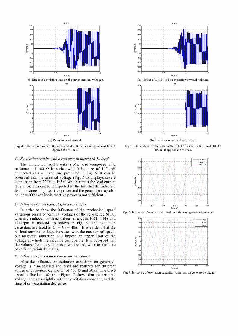
Fig. 4: Simulation results of the self-excited SPIG with a resistive load 100 Ω applied at t = 1 sec.
C. Simulation results with a resistive-inductive (R-L) load The simulation results with a R-L load composed of a
resistance of 100 Ω in series with inductance of 100 mH connected at t = 1 sec, are presented in Fig. 5. It can be observed that the terminal voltage (Fig. 5-a) displays severe attenuation from 220V to 165V, which affects the load current (Fig. 5-b). This can be interpreted by the fact that the inductive load consumes high reactive power and the generator may also collapse if the available reactive power is not sufficient.
D. Influence of mechanical speed variations In order to show the influence of the mechanical speed
variations on stator terminal voltages of the sel-excited SPIG, tests are realized for three values of speeds 1021, 1146 and 1241rpm at no-load, as shown in Fig. 6. The excitation capacitors are fixed at C1 = C2 = 40μF. It is evident that the no-load terminal voltage increases with the mechanical speed, but magnetic saturation will impose an upper limit of the voltage at which the machine can operate. It is observed that the voltage frequency increases with speed, whereas the time of self-excitation decreases.
E. Influence of excitation capacitor variations Also the influence of excitation capacitors on generated
voltage is also studied and tests are realized for different values of capacitors C1 and C2 of 40, 45 and 50μF. The drive speed is fixed at 1021rpm. Figure 7 shows that the terminal voltage increases slightly with the excitation capacitor, and the time of self-excitation decreases.
0 0.5 1 1.5-250
-200
-150
-100
-50
0
50
100
150
200
250
Time (s)
volta
ge (V
)
Vas1
(a) Effect of a R-L load on the stator terminal voltages
0 0.5 1 1.5-2.5
-2
-1.5
-1
-0.5
0
0.5
1
1.5
2
2.5
Cur
rent
(A
)Time (s)
idl1
(b) Resistive-inductive load current.
Fig. 5 : Simulation results of the self-excited SPIG with a R-L load (100 Ω, 100 mH) applied at t = 1 sec.
1 1.01 1.02 1.03 1.04 1.05 1.06
-300
-200
-100
0
100
200
300
Time (s)
Vol
tage
s (V
)
107rad/s
120rad/s
130rad/s
Fig. 6: Influence of mechanical speed variations on generated voltage.
1 1.01 1.02 1.03 1.04 1.05 1.06-250
-200
-150
-100
-50
0
50
100
150
200
250
Time (s)
Vol
tage
s (V
)
40µF
45µF
50µF
Fig. 7: Influence of excitation capacitor variations on generated voltage.
V. EXPERIMENTAL RESULTS Experiments are carried-out on an experimental test bench
to check the simulation results. The laboratory test bench consists of a dual star induction machine (DSIM: 5.5kW, 6 poles) configurable as symmetrical or asymmetrical six-phase induction machine operating as generator and coupled to a DC motor used as prime mover as shown in Fig. 8 [12]. A delta-connected capacitor bank of 45μF is linked across the terminals of the induction machine in each three-phase sets feeding electrical loads. Furthermore, the experimental tests on the SPIG are done for the same operating cases and conditions as well as the simulation tests presented above.
Fig. 8: Photography of the experimental test bench.
A. No-load experimental results The experimental results depicted by Fig. 9 at no-load case
show the initial state of the self-excitation startup of the SPIG realized with the generator driven at a constant mechanical speed of 1100 rpm and capacitors values of C1 = C2 = 45μF. It is observed from Fig. 9-a that the terminal voltage exhibits exactly the same wave forms as for the simulation case with an exponential shape which starts from an initial zero value until a steady-state having a maximum value of 220V. Also, the stator terminal voltages are well balanced and regular, as shown in Fig. 9-b for one stator winding set. It is observed that the generated voltage frequency depends on the mechanical speed. As well, the Fig. 9-c curve shows that the current circulating between the capacitor and the stator windings presents the same shape as for the stator voltage, but it is in advance of a phase angle of 90° equivalent to a purely capacitive load.
(a) Stator terminal voltages (100V/div).
(b) Zoom on the stator terminal voltages for one stator winding set (100V/div).
(c) Superposition of stator current (blue curve: 3A/div) and terminal voltage
(orange curve: 100V/div). Fig. 9: Experimental results of the self-excited SPIG at no-load with the
generator driven at 1100 rpm and C1 = C2 = 45μF.
(a) Effect of a resistive load on the stator terminal voltages (100V/div).
(b) Superposition of the resistive load current (blue curve: 1A/div) and terminal voltage (orange curve: 100V/div).
Fig. 10: Experimental results of the self-excited SPIG with a resistive load applied at t = 1 sec.
B. Experimental results with resistive load The experimental results shown in Fig. 10 displays the
terminal voltage (Fig. 10-a) and confirm the simulation results for that case and shows that the terminal voltage decreases to approximately 190V after a connection of a resistive load, and causes the decrease of the excitation capacitor current (Fig. 10-b). Also, the resistive load current superposed with the terminal voltage are exactly in phase.
C. Simulation results with a resistive-inductive (R-L) load The experimental results, with a R-L load connected at t =
1 sec are presented in Fig. 11. They also confirm the simulation results. It can be observed that the terminal voltage (Fig. 11-a) displays also severe attenuation from 220V to 170V, and affects the load current (Fig. 11-b) which is in lagging phase equivalent to the R-L load.
VI. CONCLUSION In this paper a series of simulation and experimental tests
were carried-out on a six-phase induction machine operating as a stand-alone self-excited induction generator and
supplying various loads under different conditions. So, the non-linear mathematical model of the generator has been presented considering the magnetizing inductance saturation. Then, excitation capacitors were sized to ensure the excitation task by supplying the required reactive power. The performances of the generator were strongly influenced by the excitation capacitors, drive mechanical speed and the type of load connected to its terminals. As the self-excited induction machine is an open-loop operating mode and the generated voltage amplitude and frequency depend on the rotating speed and the size of the excitation capacitors, therefore this operating mode is suitable for loads which are not sensible to voltage and frequency variations. Otherwise an adaptation stage is necessary between the generator output and the load in order to adapt the amplitude and frequency. Since, the SPIG has high number of phases, control strategies similar to that of doubly-fed induction generator can be developed and applied in order to adjust the generator output voltage and frequency. So, one stator winding set can be used for excitation purpose as control winding, while the second one can be used as power generation winding and this make this kind of machines suitable for renewable energy applications.
(a) Effect of a R-L load on the stator terminal voltages (100V/div).
(b) Superposition of the R-L load current (blue curve: 1A/div) and terminal voltage (orange curve: 100V/div).
Fig. 11: Experimental results of the self-excited SPIG with a R-L load applied at t = 1 sec.
APPENDIX The constant coefficients of the magnetizing characteristics of SEIG are
as follows:
1c = 0.5312, 2c = 1.1982, 3c = 1.0618,
4c = 2.0148, 5c = 8.6710, 6c = 1.1708.
REFERENCES [1] D. B. Watson, J. Amlaga, and T. Densem, “Controllable d.c. power
supply from wind-driven self-excited induction machines,” Proc. IEE, vol. 126, no. 12, pp. 1245-1248, 1979.
[2] J. B. Patton and D. Curtice, “Analysis of utility protection problems associated with small wind turbine interconnections,” IEEE Trans. Power Apparatus and Systems, vol. 101, no. 10, pp. 3957-3966,1982.
[3] G. Raini and O.P. Malik, “Wind energy conversion using a self-excited induction generator,” IEEE Trans. Power Apparatus and Systems, vol. 102, no. 1, pp. 3933-39362, 1983.
[4] F. Bu, Y. Hu, W. Huang, S. Zhuang and K. Shi, “Control Strategy and Dynamic Performance of Dual Stator-Winding Induction Generator Variable Frequency AC Generating System With Inductive and Capacitive Loads,” IEEE Trans. Power Electron., vol. 29, no. 4, pp. 1681–1692, Apr. 2014.
[5] E.A. Klingshirn, “High phase order induction motors-Part I: Description and Theoretical consideration,” IEEE Transactions on power Apparatus and Systems, Vol. 102, pp.47-53, 1983.
[6] Singh GK, Yadav KB and Saini R.P. “Analysis of a saturated multi-phase (six-phase) Self-excited induction generator,” International Journal of Emerging Electric Power Systems , vol 7, no 4, 2006.
[7] T. A. Lipo, “A dq model for six phase induction machines” Proc. ICEM’80, pp. 860-867, Sep.1980.
[8] P. Vas, “Sensorless vector and direct torque control,” Ed. Oxford University Press, 1998.
[9] K. Marouani, ‘‘Contribution à la commande d’un entraînement électrique à base de moteur asynchrone double étoile,’’ Phd. thesis (in french), Ecole Militaire Polytechnique, Algiers, Algeria, Jun. 2010.
[10] A. Nesba, ‘‘Caractérisation du phénomène de la saturation magnétique de la machine asynchrone,” Phd. thesis (in french), Ecole Nationale Polytechnique, Algiers, Algeria, Jan. 2007.
[11] K. Natarajan, , A. M. Sharaf, , S. Sivakumar and S. Naganathan, “ Modeling and control design for wind energy power conversion scheme using self-excited induction generator,” IEEE Trans. Energ. Conv., , 1987, , vol. EC-2, no. 3, pp. 506-512, Sap. 1982.
[12] K. Marouani, H. Guendouz, B. Tabbache, F. Khoucha and A. Kheloui, “Experimental investigation of an emulator "Hardware In the Loop" for electric naval propulsion system,” 21st IEEE-Mediterranean Conference on Control and Automation (MED), Chania, Greece, 2013.