The current European project LAPCAT II has the ambitious goal tode¦ne a conceptual vehicle capable of achieving the antipodal rangeBrussels Sydney (∼ 18,000 km) in about 2 h at Mach number Ma = 8.At this high speed, the requirement of high lift to drag (L/D) ratiois critical to high performance, because of high skin friction and wavedrag: in fact, as the Mach number increases, the L/D ratio decreases.The design of the vehicle architecture (shape and propulsion system)is, as a consequence, crucial to achieve a reasonably high L/D. In thiswork, critical parameters for the preliminary sizing of a hypersonic air-breathing airliner have been identi¦ed. In particular, for a given Technol-ogy Readiness Level (TRL) and mission requirements, a solution space ofpossible vehicle architectures at cruise have been obtained. In this work,the Gross Weight at Take-O¨ (TOGW) was deliberately discarded as aconstraint, based on previous studies by Czysz and Vanderkerkhove [1].Typically, limiting from the beginning, the TOGW leads to a viciousspiral where weight and propulsion system requirements keep growing,eventually denying convergence. In designing passenger airliners, in fact,it is the payload that is assumed ¦xed from the start, not the total weight.In order to screen the solutions found, requirements for taking-o¨ (TO)and landing as well as the trajectory have been accounted for. A con-sistent solution has ¦nally been obtained by imposing typical airlinerconstraints: emergency take-o¨ and landing. These constraints enablesingling out a realistic design from the broad family of vehicles capa-ble of performing the given mission. This vehicle has been obtained byintegrating not only aerodynamics, trajectory, and airliner constraints,but also by integrating the propulsion system, the trimming devices andby doing some adjustments to the conceptual vehicle shape (i. e., spat-ular nose). Thus, the ¦nal vehicle is the result of many iterations inthe design space, until performance, trajectory, propulsion systems, andairport constraints are successfully met.
1 INTRODUCTION
Studies on hypersonic con¦gurations in USA, Russia, and EU date back to the
early 1960s. The lesson learned in the past [1 5] is that hypersonic vehicle sizing
This is an Open Access article distributed under the terms of the Creative Commons Attribution-NoncommercialLicense 3.0, which permits unrestricted use, distribution, and reproduction in any noncommercial medium, pro-vided the original work is properly cited.
Article available at http://www.eucass-proceedings.eu or http://dx.doi.org/10.1051/eucass/201102487
The sizing approach followed here is based on the so-called VDK/HC [1] para-
metric sizing methodology. This methodology was developed since the 1980s and
applied to: high-performance subsonic to hypersonic aircraft; and reusable space
launchers. For a cruising vehicle, the sizing begins with the mission distance, pay-
load, and cruise Mach number to obtain a ¦gure of merit (the Kuechemann£s τ)for the whole vehicle. The VDK sizing methodology is based on the simultaneous
solution for the OWE (overall weight empty) and planform area Splan equations,ensuring that the separately calculated available and required weights and
total volumes (Vtot) converge for a given τ [2], de¦ned as τ =(Vtot/S1.5plan
).
Note that all sizing variables in these calculations are strictly connected to
each other. For example, if the range increases, the propellant weight also in-
creases. The increase of the propellant weight raises that of all systems and of
the structure. The same occurs for the propellant volume: increasing its volume
raises drag, and to keep the L/D ratio reasonable, a larger planform surface is
needed to produce higher lift. However, a larger planform area means a more
wetted area hence the structural weigh increases too, and the larger TOGW
requires more propellant. Thus, this process may diverge, and that is why a
solution must be found by solving simultaneously the set of equations that relate
all dependent variables (volumes, weights, and vehicle geometry) to the mission
input (Ma, L/D, range, and payload). Since these equations are nonlinear, they
must be iterated until, for instance, the volume required (from the desired per-
formance and constraints) is equal to the volume available (from aerodynamics
and structure). The same holds in terms of weight.
For a given mission requirements, more than one con¦guration can be found,
and it is the constraints of mission typology (commercial aircraft, space plane,
launcher, etc.) that will eventually de¦ne the ¤best con¦guration.¥
2 VEHICLE DESIGN
In [5], the present authors have found a solution space of aircraft con¦gurations
for given design speci¦cations (cruise Ma = 8, range = 18.728 km, number of
488
AIR-BREATHING PROPULSION
passengers = 300 (Wpay = 60 t), and hydrogen fuel) by solving simultaneouslyall ¤cruise¥ equations.
At cruise, the initial guess to de¦ne a tentative conceptual vehicle consisted
of Isp = 2000 s and engine thrust-to-weight T/W = 8.3. The variables related tothe current state of industrial technology (Istr) were also assumed [3]: Istr = 21and 22 kg/m2, Wsys/TOGW = rsys = 0.07 (Wsys is the weight of all systems),ηv = 0.7 (useable volume ratio).At convergence, the solutions were found for four reference con¦gurations
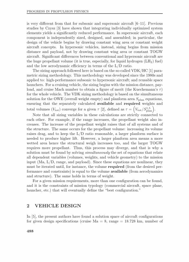
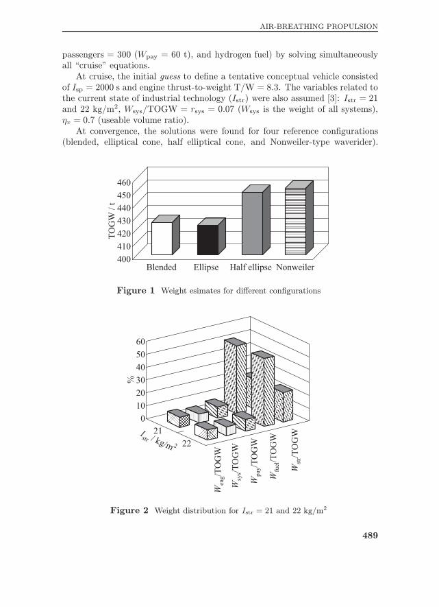
(blended, elliptical cone, half elliptical cone, and Nonweiler-type waverider).
Figure 1 Weight esimates for di¨erent con¦gurations
Figure 2 Weight distribution for Istr = 21 and 22 kg/m2
489
PROGRESS IN PROPULSION PHYSICS
Comparing the weight estimates for the di¨erent con¦gurations (Fig. 1), the
ellipse and blended body have been found to be the most promising, that is,
predicting the lowest TOGW (∼ 420 t).Figure 2 shows the weight distribution among the vehicle main components
for a blended body con¦guration. This ¦gure shows that for this (extreme)
mission, the vehicle is fuel dominated. In Fig. 2, Weng is the engine weight.Note, these results apply only to the cruise phase: the trajectory has not yet
been included. The next step is then to de¦ne a trajectory and recalculate the
converged con¦guration including take-o¨ and landing.
3 PRELIMINARY TRAJECTORY SELECTION
The reference trajectory has been calculated by means of a Numerical Energy
Method. This method [3] involves the linearization of the equations of motion in
order to obtain closed-form expressions for the desired performance parameters.
These expressions are applied over ¦nite velocity intervals where the aerody-
namics, propulsion and §ight path parameters are assumed to be constant. The
method is extended by a rapidly converging iteration procedure to estimate climb
performance for a §ight path limited by sonic boom considerations and assuming
the following (during climb-out):
constant velocity climb-out to 3048 m;
constant altitude acceleration to Mach 0.8;
constant Mach 0.8 climb to 11,000 m;
acceleration to the maximum dynamic pressure;
constant dynamic pressure climb to 30,000 m;
cruise, including climb to the maximum altitude; and
maximum L/D descent.
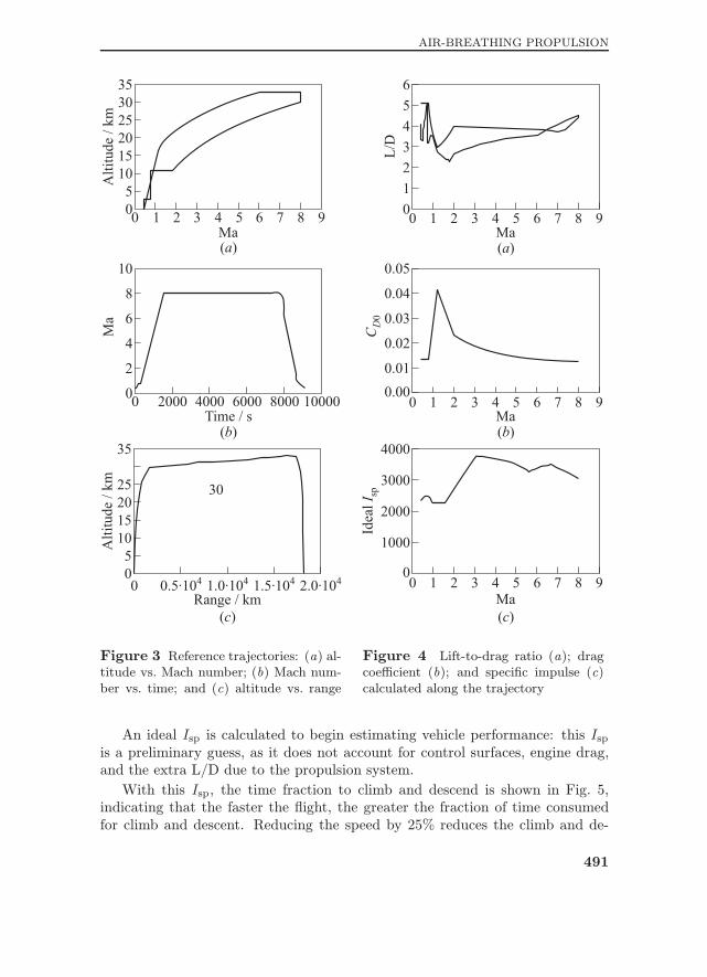
Figures 3a to 3c show the reference trajectory. This trajectory has a pro¦le
similar to HyFAC and HyCAT studies [12, 13]. Limiting acceleration to 0.3g,the time to climb is 14.4 min, cruise time is of 106.9 min, and descent time is
An ideal Isp is calculated to begin estimating vehicle performance: this Ispis a preliminary guess, as it does not account for control surfaces, engine drag,
and the extra L/D due to the propulsion system.
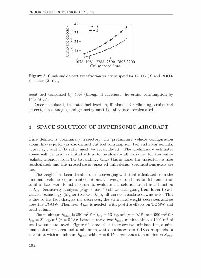
With this Isp, the time fraction to climb and descend is shown in Fig. 5,indicating that the faster the §ight, the greater the fraction of time consumed
for climb and descent. Reducing the speed by 25% reduces the climb and de-
491
PROGRESS IN PROPULSION PHYSICS
Figure 5 Climb and descent time fraction vs. cruise speed for 12,000- (1) and 18,000-kilometer (2) range
scent fuel consumed by 50% (though it increases the cruise consumption by
15% 20%)!
Once calculated, the total fuel fraction, ¨, that is for climbing, cruise and
descent, mass budget, and geometry must be, of course, recalculated.
4 SPACE SOLUTION OF HYPERSONIC AIRCRAFT
Once de¦ned a preliminary trajectory, the preliminary vehicle con¦guration
along this trajectory is also de¦ned but fuel consumption, fuel and gross weights,
actual Isp, and L/D ratio must be recalculated. The preliminary estimatesabove will be used as initial values to recalculate all variables for the entire
realistic mission, from TO to landing. Once this is done, the trajectory is also
recalculated, and this procedure is repeated until design speci¦cations goals are
met.
The weight has been iterated until converging with that calculated from the
minimum volume requirement equations. Converged solutions for di¨erent struc-
tural indices were found in order to evaluate the solution trend as a function
of Istr. Sensitivity analysis (Figs. 6 and 7) shows that going from lower to ad-vanced technology (higher to lower Istr), all curves translate downwards. Thisis due to the fact that, as Istr decreases, the structural weight decreases and sodoes the TOGW. Then less Wfuel is needed, with positive e¨ects on TOGW andtotal volume.
The minimum Splan is 850 m2 for Istr = 13 kg/m
2 (τ = 0.18) and 980 m2 forIstr = 21 kg/m
2 (τ = 0.18): between these two Splan minima almost 1000 m3 of
total volume are saved. Figure 6b shows that there are two minima, i. e., a min-
imum planform area and a minimum wetted surface: τ = 0.18 corresponds toa solution with a minimum Splan, while τ = 0.15 corresponds to a minimum Swet.
492
AIR-BREATHING PROPULSION
Figure 6 Total volume (Vtot) (a), Swet (b), Wstr (c), and OWE (d) vs. Splan: 1 ¡Istr = 13 kg/m
These two solutions are very close; for example, for Istr = 21 kg/m2, they go
from about 2750 m2 at 970 m2 to 2700 m2 at 1000 m2, but there is still a range
of solutions in-between to choose from.
A minimum Swet means a minimum structural weight, i. e., 56 t at τ= 0.15. Figure 6c shows that the structural weight, Wstr, has two closely spacedminima that are very reasonable at high skin temperature cruise (when the mass
of the TPS is signi¦cant): in fact, at the minimum Splan (corresponding to τ= 0.18), the structural weight is only 2 t more than that of the minimum Swet.
Figure 6c also shows that going from Istr = 21 to 13 kg/m2, the structural
weight decreases by about 26 t, going from 56 to 30 t for the two Swet minima;almost 700 m3 are saved between these two Swet minima.
Going from Istr = 15 to 21 kg/m2, the Operational Weight Empty (OWE)
varies by about 40 t for τ = 0.15 (corresponding to the minimum Swet). TheTOGW goes from 275 to 350 t, saving 75 t. Figure 7b shows that for Istr= 21 kg/m2, the OWE range is between 205 to 207 t for the two minima: the
range of empty weights is only 2 t (∼ 1%). Unlike the broad solution locus
493
PROGRESS IN PROPULSION PHYSICS
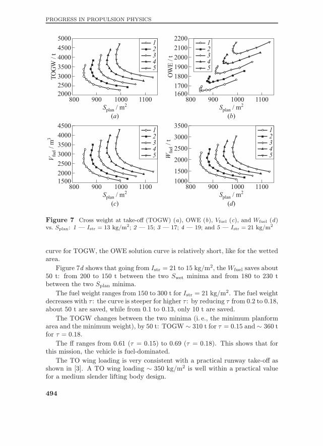
Figure 7 Cross weight at take-o¨ (TOGW) (a), OWE (b), Vfuel (c), and Wfuel (d)
curve for TOGW, the OWE solution curve is relatively short, like for the wetted
area.
Figure 7d shows that going from Istr = 21 to 15 kg/m2, theWfuel saves about
50 t: from 200 to 150 t between the two Swet minima and from 180 to 230 tbetween the two Splan minima.
The fuel weight ranges from 150 to 300 t for Istr = 21 kg/m2. The fuel weight
decreases with τ : the curve is steeper for higher τ : by reducing τ from 0.2 to 0.18,about 50 t are saved, while from 0.1 to 0.13, only 10 t are saved.
The TOGW changes between the two minima (i. e., the minimum planform
area and the minimum weight), by 50 t: TOGW ∼ 310 t for τ = 0.15 and ∼ 360 tfor τ = 0.18.
The ¨ ranges from 0.61 (τ = 0.15) to 0.69 (τ = 0.18). This shows that forthis mission, the vehicle is fuel-dominated.
The TO wing loading is very consistent with a practical runway take-o¨ as
shown in [3]. A TO wing loading ∼ 350 kg/m2 is well within a practical valuefor a medium slender lifting body design.
494
AIR-BREATHING PROPULSION
5 COMMERCIAL AIRCRAFT CONSTRAINTS
AND VEHICLE SELECTION
Once found a hypersonic vehicle space solution, commercial aircraft con-
straints [14] must be accounted for the selection of the best solution within
the range of convergence. In particular:
for passenger comfort: limit axial acceleration a ≤ 0.3g; and compliance with important JAR ¦eld performance requirements means:
• TO with one engine inoperative climb requirement [14];• emergency landing with high fuel load (CLmax, W/S where W= TOGW and S is Splan); and
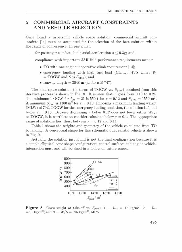
• runway length = 3048 m (as for a B-747).The ¦nal space solution (in terms of TOGW vs. Splan) obtained from this
iterative process is shown in Fig. 8. It is seen that τ goes from 0.10 to 0.24.The minimum TOGW for Istr = 21 is 550 t for τ = 0.12 and Splan = 1550 m
2.
A minimum Splan is 1300 m2 for τ = 0.18. Imposing a maximum landing weight
(MLW) of 70% TOGW for the emergency landing condition, the solution is found
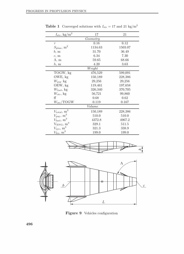
below τ = 0.16. Because decreasing τ below 0.12 does not lower either Wfuelor TOGW, it is worthless to consider solutions below τ = 0.1. The appropriaterange of solutions lies, thus, between τ = 0.12 and 0.14.Table 1 shows the weights and geometry of the vehicle calculated from TO
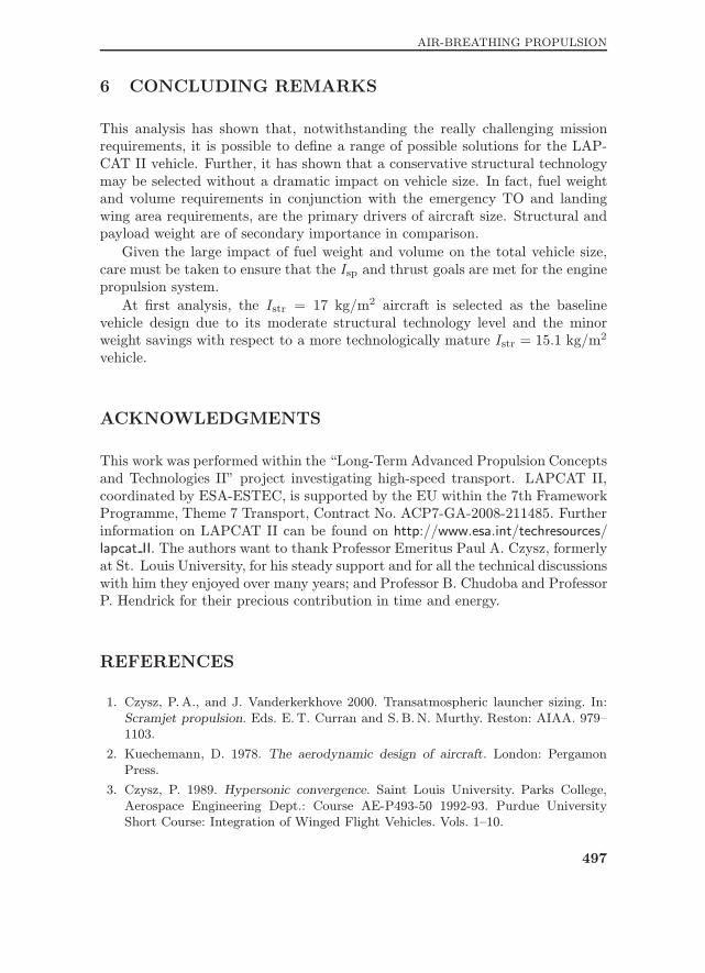
to landing. A conceptual shape for this schematic but realistic vehicle is shown
in Fig. 9.
Actually, the solution just found is not the ¦nal con¦guration because it is
a simple elliptical cone-shape con¦guration: control surfaces and engine vehicle-
integration must and will be sized in a follow-on future paper.
Figure 8 Cross weight at take-o¨ vs. Splan: 1 ¡ Istr = 17 kg/m2; 2 ¡ Istr
= 21 kg/m2; and 3 ¡ W/S = 395 kg/m2, MLW
495
PROGRESS IN PROPULSION PHYSICS
Table 1 Converged solutions with Istr = 17 and 21 kg/m2
Istr, kg/m2 17 21
Geometry
τ 0.16 0.12
Splan, m2 1134.63 1503.07
b, m 31.70 36.49
c, m 6.34 7.30
˜, m 59.65 68.66
h, m 4.20 3.63
Weight
TOGW, kg 476,529 599,091
OWE, kg 150,189 228,386
Wpay kg 29,256 29,256
OEW, kg 119,461 197,658
Wfuel, kg 326,340 370,705
Wstr, kg 56,721 99,860
¨ 0.68 0.62
Wstr/TOGW 0.119 0.167
Volume
Vtotal, m3 150,189 228,386
Vpay, m3 510.0 510.0
Vfuel, m3 4372.8 4967.2
VENG, m3 329.1 511.5
Vsys, m3 321.3 338.9
V¦x, m3 199.0 199.0
Figure 9 Vehicles con¦guration
496
AIR-BREATHING PROPULSION
6 CONCLUDING REMARKS
This analysis has shown that, notwithstanding the really challenging mission
requirements, it is possible to de¦ne a range of possible solutions for the LAP-
CAT II vehicle. Further, it has shown that a conservative structural technology
may be selected without a dramatic impact on vehicle size. In fact, fuel weight
and volume requirements in conjunction with the emergency TO and landing
wing area requirements, are the primary drivers of aircraft size. Structural and
payload weight are of secondary importance in comparison.
Given the large impact of fuel weight and volume on the total vehicle size,
care must be taken to ensure that the Isp and thrust goals are met for the enginepropulsion system.
At ¦rst analysis, the Istr = 17 kg/m2 aircraft is selected as the baseline
vehicle design due to its moderate structural technology level and the minor
weight savings with respect to a more technologically mature Istr = 15.1 kg/m2
vehicle.
ACKNOWLEDGMENTS
This work was performed within the ¤Long-Term Advanced Propulsion Concepts
and Technologies II¥ project investigating high-speed transport. LAPCAT II,
coordinated by ESA-ESTEC, is supported by the EU within the 7th Framework
Programme, Theme 7 Transport, Contract No. ACP7-GA-2008-211485. Further
information on LAPCAT II can be found on http://www.esa.int/techresources/lapcat II. The authors want to thank Professor Emeritus Paul A. Czysz, formerlyat St. Louis University, for his steady support and for all the technical discussions
with him they enjoyed over many years; and Professor B. Chudoba and Professor
P. Hendrick for their precious contribution in time and energy.
REFERENCES
1. Czysz, P.A., and J. Vanderkerkhove 2000. Transatmospheric launcher sizing. In: