66
V1.2 SK-FM3-64PMC1 (-JLINK) All Rights Reserved.© Fujitsu Limited 2011
V1.2
SK-FM3-64PMC1 (-JLINK)
All Rights Reserved.© Fujitsu Limited 2011

Fujitsu Semiconductor Europe - http://emea.fujitsu.com/microelectronics
Warranty and Disclaimer
The use of the deliverables (e.g. software, application examples, target boards, evaluation boards, starter kits, schematics, engineering samples of IC’s etc.) is subject to the conditions of Fujitsu Semiconductor Europe GmbH (“FSEU”) as set out in (i) the terms of the License Agreement and/or the Sale and Purchase Agreement under which agreements the Product has been delivered, (ii) the technical descriptions and (iii) all accompanying written materials.Please note that the deliverables are intended for and must only be used for reference in an evaluation laboratory environment.The software deliverables are provided on an as-is basis without charge and are subject to alterations. It is the user’s obligation to fully test the software in its environment and to ensure proper functionality, qualification and compliance with component specifications.Regarding hardware deliverables, FSEU warrants that they will be free from defects in material and workmanship under use and service as specified in the accompanying written materials for a duration of 1 year from the date of receipt by the customer.Should a hardware deliverable turn out to be defect, FSEU’s entire liability and the customer’s exclusive remedy shall be, at FSEU´ssole discretion, either return of the purchase price and the license fee, or replacement of the hardware deliverable or parts thereof, if
the deliverable is returned to FSEU in original packing and without further defects resulting from the customer’s use or the transport. However, this warranty is excluded if the defect has resulted from an accident not attributable to FSEU, or abuse or misapplication attributable to the customer or any other third party not relating to FSEU or to unauthorised decompiling and/or reverse engineering and/or disassembling.FSEU does not warrant that the deliverables do not infringe any third party intellectual property right (IPR). In the event that the deliverables infringe a third party IPR it is the sole responsibility of the customer to obtain necessary licenses to continue the usage of the deliverable.In the event the software deliverables include the use of open source components, the provisions of the governing open source license agreement shall apply with respect to such software deliverables. To the maximum extent permitted by applicable law FSEU disclaims all other warranties, whether express or implied, in particular, but not limited to, warranties of merchantability and fitness for a particular purpose for which the deliverables are not designated.To the maximum extent permitted by applicable law, FSEU’s liability is restricted to intention and gross negligence. FSEU is not liable for consequential damages.Should one of the above stipulations be or become invalid and/or unenforceable, the remaining stipulations shall stay in full effect.The contents of this document are subject to change without a prior notice, thus contact FSEU about the latest one.
This board and its deliverables must only be used for test applications in an evaluation laboratory environment.
All Rights Reserved.© Fujitsu Limited 2010
2
Fujitsu Semiconductor Europe - http://emea.fujitsu.com/microelectronics
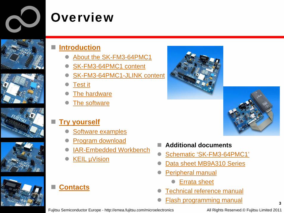
Overview
IntroductionAbout the SK-FM3-64PMC1SK-FM3-64PMC1 contentSK-FM3-64PMC1-JLINK contentTest itThe hardwareThe software
Try yourselfSoftware examplesProgram downloadIAR-Embedded WorkbenchKEIL µVision
Contacts
All Rights Reserved.© Fujitsu Limited 2011
3
Additional documentsSchematic ‘SK-FM3-64PMC1’Data sheet MB9A310 SeriesPeripheral manual
Errata sheet Technical reference manualFlash programming manual

Fujitsu Semiconductor Europe - http://emea.fujitsu.com/microelectronics
About the SK-FM3-64PMC1
The SK-FM3-64PMC1 is available in two versions:The SK-FM3-64PMC1 includes a low-cost evaluation board based on the Fujitsu FM3 microcontroller MB9A310 Series
SK-FM3-64PMC1-JLINK includes a low-cost evaluation board based on the Fujitsu FM3 microcontroller MB9A310 Series and the JTAG adapter J-Link
The MB9A310 Series includes the following features:Up to 512 KByte Flash MemoryUp to 32 KByte RAMUp to 8 LIN-USART-I²C interfacesUSB-Host/-Device interfaceTimers (ICUs, OCUs, PPGs, others)Up to three 12 bit ADCExternal interruptsLow Power ModeDMA Controller (8 channels)
All Rights Reserved.© Fujitsu Limited 2011
4

Fujitsu Semiconductor Europe - http://emea.fujitsu.com/microelectronics
About the SK-FM3-64PMC1
Features of the SK-FM3-64PMC1 board:
Microcontroller MB9AF314L1x UART-Transceiver (SUB-D9 connector)1x USB to serial converter (Type-B connector)1x USB-MiniHost (Type-A connector)1x USB-Device (Type-B connector)JTAG-Interface on a 20 pin-headerTSC-Interface to connect for example the Fujitsu SK-TSC-1127S-SB2x LED-Display (7-Segment)2x ‘User’-button1x ‘Reset’-button, ‘Reset’-LEDAll 64 pins routed to pin-headerOn-board 5V and 3V voltage regulators, ‘Power’-LEDPower supply via USB (UART’B’), USB-Device, JTAG or external via a 8V to 12V power connectorVoltage filter for ADC
5All Rights Reserved.© Fujitsu Limited 2011

Fujitsu Semiconductor Europe - http://emea.fujitsu.com/microelectronics
SK-FM3-64PMC1 content
The SK-FM3-64PMC1 kit containsSK-FM3-64PMC1 evaluation board with MB9AF314LUSB cableCD: Documentation, USB driver, Software examples, Programmer
All Rights Reserved.© Fujitsu Limited 2011
6
ESD-foam ESD-box SK-FM3-64PMC1 USB cable
A B
CD Additional information
Fujitsu Semiconductor Europe - http://emea.fujitsu.com/microelectronics
SK-FM3-64PMC1-JLINK content
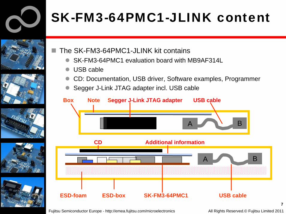
The SK-FM3-64PMC1-JLINK kit containsSK-FM3-64PMC1 evaluation board with MB9AF314LUSB cableCD: Documentation, USB driver, Software examples, ProgrammerSegger J-Link JTAG adapter incl. USB cable
All Rights Reserved.© Fujitsu Limited 2011
7
ESD-foam ESD-box SK-FM3-64PMC1 USB cable
A B
CD Additional information
A B
Box Note Segger J-Link JTAG adapter USB cable

Fujitsu Semiconductor Europe - http://emea.fujitsu.com/microelectronics
Test it
The microcontroller on the SK-FM3-64PMC1 is already preprogrammed with a simple application.
Connect the SK-FM3-64PMC1 via USB (X5) with the PC, verify that jumper J5 is on the USBPWR position.Install the USB driver from the CDPress the ‚Reset‘- ButtonThe SK-FM3-64PMC1 will automatically start countingThe count direction can be changed by pressing the key buttons
8
INT0
INT1
All Rights Reserved.© Fujitsu Limited 2011

Fujitsu Semiconductor Europe - http://emea.fujitsu.com/microelectronics
Test it
You finished successfully the first test
Now you will get more details about the SK-FM3-64PMC1You will learn more about
The on-board featuresHow to program the FlashHow to start with IAR-Embedded-Workbench and KEIL µVision
9All Rights Reserved.© Fujitsu Limited 2011

Fujitsu Semiconductor Europe - http://emea.fujitsu.com/microelectronics
Main features
The Hardware
10All Rights Reserved.© Fujitsu Limited 2011
USBDevice
USBHost
UART ‚A‘ Ext Power+8V...+12V
7-Segment Display
P01_1P01_7
P01_3
P01_2P01_4
P01_5
P01_0
P03_AP03_F
P03_C
P03_BP03_D
P03_E
P03_9
P03_2
SEG1: Port39-3F SEG2: Port10-17P03_3
USB to UART ‚B‘
Keybutton ‚Reset‘
Keybutton ‚INT1‘Port P05_1
Keybutton ‚INT0‘Port P05_0
LED ‚Power‘TSC
(Touch-Sensor Connector)
JTAG J-Link
LED ‚Reset‘
Fujitsu Semiconductor Europe - http://emea.fujitsu.com/microelectronics
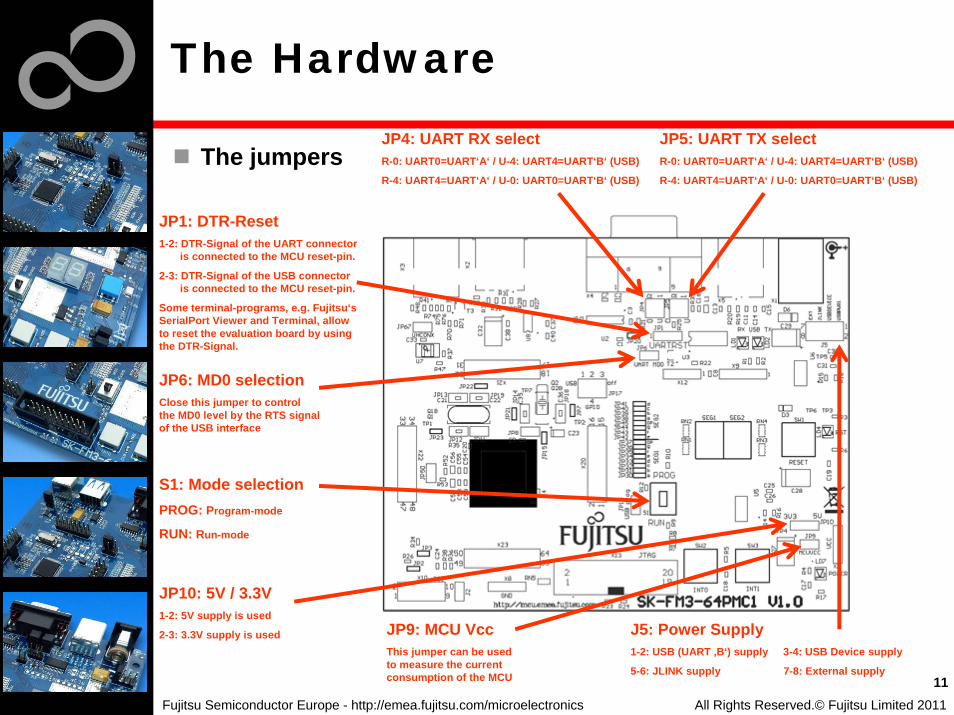
The jumpers
The Hardware
11
JP4: UART RX selectR-0: UART0=UART‘A‘ / U-4: UART4=UART‘B‘ (USB)
R-4: UART4=UART‘A‘ / U-0: UART0=UART‘B‘ (USB)
JP5: UART TX selectR-0: UART0=UART‘A‘ / U-4: UART4=UART‘B‘ (USB)
R-4: UART4=UART‘A‘ / U-0: UART0=UART‘B‘ (USB)
JP6: MD0 selectionClose this jumper to controlthe MD0 level by the RTS signalof the USB interface
S1: Mode selectionPROG: Program-mode
RUN: Run-mode
JP10: 5V / 3.3V1-2: 5V supply is used
2-3: 3.3V supply is used
JP1: DTR-Reset1-2: DTR-Signal of the UART connector
is connected to the MCU reset-pin.
2-3: DTR-Signal of the USB connector is connected to the MCU reset-pin.
Some terminal-programs, e.g. Fujitsu‘s SerialPort Viewer and Terminal, allow to reset the evaluation board by using the DTR-Signal.
JP9: MCU VccThis jumper can be usedto measure the currentconsumption of the MCU
J5: Power Supply1-2: USB (UART ‚B‘) supply 3-4: USB Device supply
5-6: JLINK supply 7-8: External supply
All Rights Reserved.© Fujitsu Limited 2011

Fujitsu Semiconductor Europe - http://emea.fujitsu.com/microelectronics
The jumpers
The Hardware
12
JP67: USB Function HCONX
Open: D+ is not pulled upClosed: HCONX controls Pullup
of D+
JP17: Port8 (USB use)1-2: USB in use2-3: USB not in use2-4: Use Port 8 as digital I/O
JP16: USB prog (for PROG-Mode S1)
Open: UART programming enabled
Closed: USB programming enabled
JP2: Pullup resistor TSCClosed: Pullup SCL3
JP3: Pullup resistor TSCClosed: Pullup SDA3
All Rights Reserved.© Fujitsu Limited 2011
Special solder-jumpers: These jumpers are bridged (default:closed) and enable the function described. To open them
just cut the space between the pins, and the function will be disabled. It‘s useful for current measurements or to use the
assigned ports for a different function from the default.
JP30-JP45: SEG1 and SEG2
JP21: Subclock (Open: P47)
JP7: Subclock (Open: P46)
JP15: C-pin (Capacitor function?)
JP20:Use of UART‘A‘
Fujitsu Semiconductor Europe - http://emea.fujitsu.com/microelectronics
The Hardware
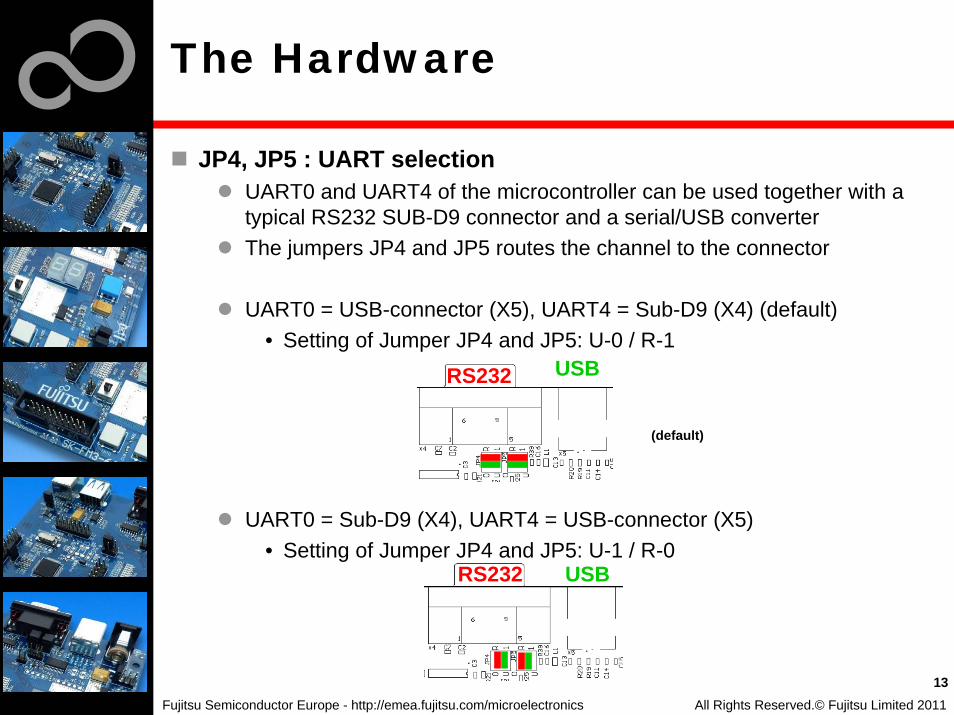
JP4, JP5 : UART selectionUART0 and UART4 of the microcontroller can be used together with a typical RS232 SUB-D9 connector and a serial/USB converterThe jumpers JP4 and JP5 routes the channel to the connector
UART0 = USB-connector (X5), UART4 = Sub-D9 (X4) (default)• Setting of Jumper JP4 and JP5: U-0 / R-1
UART0 = Sub-D9 (X4), UART4 = USB-connector (X5)• Setting of Jumper JP4 and JP5: U-1 / R-0
13
USBRS232
All Rights Reserved.© Fujitsu Limited 2011
USBRS232
(default)
Fujitsu Semiconductor Europe - http://emea.fujitsu.com/microelectronics
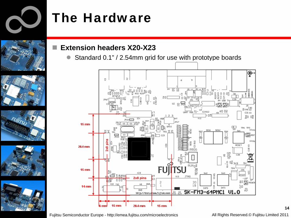
Extension headers X20-X23Standard 0.1” / 2.54mm grid for use with prototype boards
14All Rights Reserved.© Fujitsu Limited 2011
The Hardware
2x8 pins

Fujitsu Semiconductor Europe - http://emea.fujitsu.com/microelectronics
The Hardware
The microcontroller pins
15
Pin Pin-namePin-Function on SK-FM3-64PMC1
Pin Pin-namePin-Function on SK-FM3-64PMC1
1 VCC MCUVCC 12 P3C/RTO02_0/TIOA2_1 SEG1-D
2 P50/INT00_0/AIN0_2/SIN3_1 Key button ‘INT0’ 13 P3D/RTO03_0/TIOA3_1 SEG1-E
3 P51/INT01_0/BIN0_2/SOT3_1 Key button ‘INT1’ 14 P3E/RTO04_0/TIOA4_1 SEG1-F
4 P52/INT02_0/ZIN0_2/SCK3_1 USB current limitation‘INT2’ 15 P3F/RTO05_0/TIOA5_1 SEG1-G
5 P30/AIN0_0/TIOB0_1/INT03_2 TINT TSC-Con-nector ‘INT32’ 16 VSS GND
6 P31/BIN0_0/TIOB1_1/SCK6_1/INT04_2 GINT TSC-Con-nector ‘INT42’ 17 C ‘C’ capacitor
7 P32/ZIN0_0/TIOB2_1/SOT6_1/INT05_2 SEG1-DP 18 VCC MCUVCC
8 P33/INT04_0/TIOB3_1/SIN6_1/ADTG_6 SEG2-DP 19 P46/X0ASubclock(optional)
9 P39/DTTI0X_0/ADTG_2 SEG1-A 20 P47/X1ASubclock(optional)
10 P3A/RTO00_0/TIOA0_1 SEG1-B 21 INITX Key button ‚Reset‘
11 P3B/RTO01_0/TIOA1_1 SEG1-C 22 P49/TIOB0_0/AIN0_1
All Rights Reserved.© Fujitsu Limited 2011
Fujitsu Semiconductor Europe - http://emea.fujitsu.com/microelectronics
The Hardware
The microcontroller pins (cont‘d)
16
Pin Pin-namePin-Function on SK-FM-100PMC
Pin Pin-namePin-Function on SK-FM-100PMC
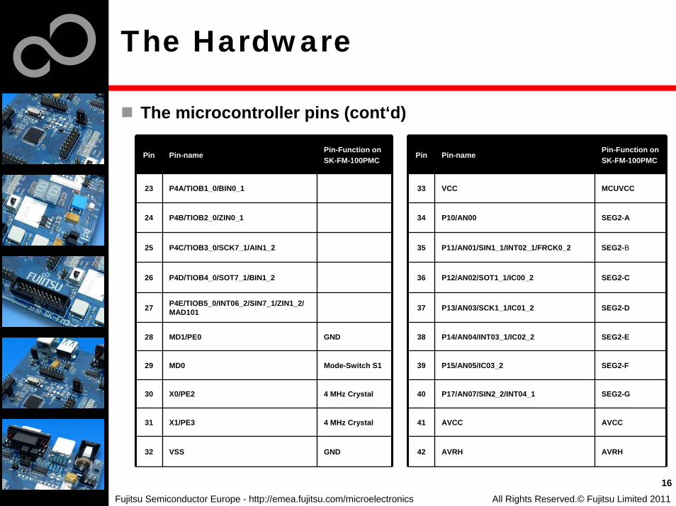
23 P4A/TIOB1_0/BIN0_1 33 VCC MCUVCC
24 P4B/TIOB2_0/ZIN0_1 34 P10/AN00 SEG2-A
25 P4C/TIOB3_0/SCK7_1/AIN1_2 35 P11/AN01/SIN1_1/INT02_1/FRCK0_2 SEG2-B
26 P4D/TIOB4_0/SOT7_1/BIN1_2 36 P12/AN02/SOT1_1/IC00_2 SEG2-C
27 P4E/TIOB5_0/INT06_2/SIN7_1/ZIN1_2/MAD101 37 P13/AN03/SCK1_1/IC01_2 SEG2-D
28 MD1/PE0 GND 38 P14/AN04/INT03_1/IC02_2 SEG2-E
29 MD0 Mode-Switch S1 39 P15/AN05/IC03_2 SEG2-F
30 X0/PE2 4 MHz Crystal 40 P17/AN07/SIN2_2/INT04_1 SEG2-G
31 X1/PE3 4 MHz Crystal 41 AVCC AVCC
32 VSS GND 42 AVRH AVRH
All Rights Reserved.© Fujitsu Limited 2011
Fujitsu Semiconductor Europe - http://emea.fujitsu.com/microelectronics
The Hardware
The microcontroller pins (cont‘d)
17
Pin Pin-namePin-Function on SK-FM-100PMC
Pin Pin-namePin-Function on SK-FM-100PMC
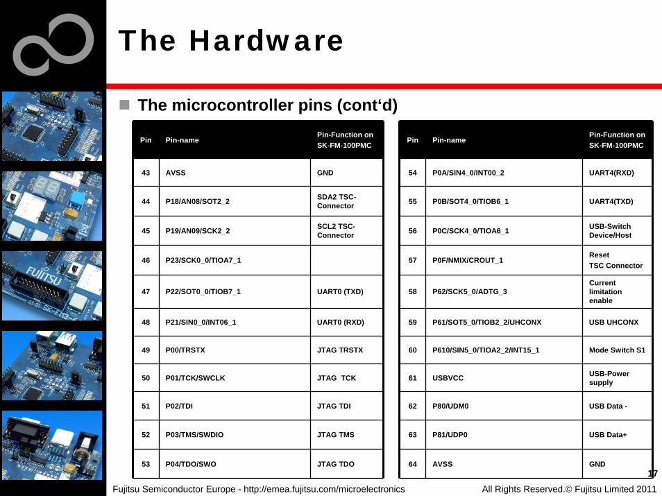
43 AVSS GND 54 P0A/SIN4_0/INT00_2 UART4(RXD)
44 P18/AN08/SOT2_2 SDA2 TSC-Connector 55 P0B/SOT4_0/TIOB6_1 UART4(TXD)
45 P19/AN09/SCK2_2 SCL2 TSC-Connector 56 P0C/SCK4_0/TIOA6_1 USB-Switch
Device/Host
46 P23/SCK0_0/TIOA7_1 57 P0F/NMIX/CROUT_1ResetTSC Connector
47 P22/SOT0_0/TIOB7_1 UART0 (TXD) 58 P62/SCK5_0/ADTG_3Current limitation enable
48 P21/SIN0_0/INT06_1 UART0 (RXD) 59 P61/SOT5_0/TIOB2_2/UHCONX USB UHCONX
49 P00/TRSTX JTAG TRSTX 60 P610/SIN5_0/TIOA2_2/INT15_1 Mode Switch S1
50 P01/TCK/SWCLK JTAG TCK 61 USBVCC USB-Power supply
51 P02/TDI JTAG TDI 62 P80/UDM0 USB Data -
52 P03/TMS/SWDIO JTAG TMS 63 P81/UDP0 USB Data+
53 P04/TDO/SWO JTAG TDO 64 AVSS GND
All Rights Reserved.© Fujitsu Limited 2011

Fujitsu Semiconductor Europe - http://emea.fujitsu.com/microelectronics
The Software
The SK-FM3-64PMC1 CD includes the following software:MCU Flash programming tools
FUJITSU FLASH MCU Programmer for FM3FLASH USB DIRECT Programmer
USB driver for on-board USB-to-RS232 converterThe terminal program SerialPortViewerAndTerminalSoftware examples for the SK-FM3-64PMC1
Please check our dedicated microcontroller website:
for updates of the Flash programmer tool, utilities and examplesfor data sheets, hardware manuals, application notes, etc.
18All Rights Reserved.© Fujitsu Limited 2011
Fujitsu Semiconductor Europe - http://emea.fujitsu.com/microelectronics
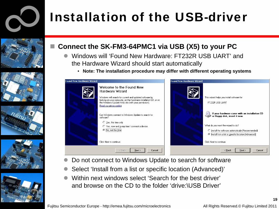
Installation of the USB-driver
Connect the SK-FM3-64PMC1 via USB (X5) to your PCWindows will ‘Found New Hardware: FT232R USB UART’ and the Hardware Wizard should start automatically
• Note: The installation procedure may differ with different operating systems
Do not connect to Windows Update to search for software Select ‘Install from a list or specific location (Advanced)’Within next windows select ‘Search for the best driver’and browse on the CD to the folder ‘drive:\USB Driver’
19All Rights Reserved.© Fujitsu Limited 2011

Fujitsu Semiconductor Europe - http://emea.fujitsu.com/microelectronics
Installation of the USB-driver
‘Continue anyway’ although the Windows Logo test may not be passedWindows completes the installation by copying some files‘Finish’ will close the window
20All Rights Reserved.© Fujitsu Limited 2011

Fujitsu Semiconductor Europe - http://emea.fujitsu.com/microelectronics
Installation of the USB-driver
Again Windows will ‘Found New Hardware: USB Serial Port’ and the Hardware Wizard should start automatically
• Note: The installation procedure may differ with different operating systems
Do not connect to Windows Update to search for software Select ‘Install from a list or specific location (Advanced)’Within next windows select ‘Search for the best driver’and browse on the CD to the folder ‘‘drive:\USB Driver’’
21All Rights Reserved.© Fujitsu Limited 2011

Fujitsu Semiconductor Europe - http://emea.fujitsu.com/microelectronics
Installation of the USB-driver
‘Continue anyway’ although the Windows Logo test may not be passedWindows completes the installation by copying some files
22All Rights Reserved.© Fujitsu Limited 2011

Fujitsu Semiconductor Europe - http://emea.fujitsu.com/microelectronics
Installation of the USB-driver
Start the Device Manager of the Windows Control Panel
START -> Settings -> Control Panel Control Panel -> System -> Hardware -> Device Manager
Check ‘Ports’ for the assigned virtual COM-port number
USB Serial Port (e.g.: COM2)
Open the Fujitsu‘s „SerialPort Viewer and Terminal“
Double click on the icon of the taskbar.
It will show the opened ports, check for the assigned virtual COM-port number
USB Serial Port (e.g.: COM2)
All Rights Reserved.© Fujitsu Limited 2011
23
Ready!
There are two options to check that your installation was successful:

Fujitsu Semiconductor Europe - http://emea.fujitsu.com/microelectronics
Tools and Software Examples
SerialPortViewerAndTerminal Free of charge terminal programStart installation
Following examples are provided with SK-FM3-64PMC1 forIAR Embedded Workbench V6.2 and KEIL µVision4:
mb9af314l_template-v12 • ‚Empty‘ project as base for user applications
mb9af314l_adc_dvm-v12• Digital Voltage Meter based on the A/D-converter
mb9af314l_uart-v12• Simple UART example (UART0)
mb9af314l_ioport_counter-v12• Counts from 0 to 99 on the 7-segment Display
Further examples are available on the CD and on our website
Note: Please copy the examples to your local drive!
24All Rights Reserved.© Fujitsu Limited 2011

Fujitsu Semiconductor Europe - http://emea.fujitsu.com/microelectronics
Flash Programming
There are two options to program the flash:
1. UART Programming (X4, X5)• Check jumper JP16 is opened• Connect UART0 of the board to the USB-Port of the PC
– via USB (JP4,JP5: U-0, R-1)– via RS232 (JP4,JP5: U-1, R-0)
• Use the FUJITSU FLASH MCU Programmer
2. USB Programming (X3)• Check jumper JP16 is closed• Connect the board via USB-Device (X3) to the USB-Port of the PC• Use the FLASH USB DIRECT Programmer
All Rights Reserved.© Fujitsu Limited 2011
25

Fujitsu Semiconductor Europe - http://emea.fujitsu.com/microelectronics
FUJITSU FLASH MCU Programmer for UART Programming
FUJITSU FLASH MCU ProgrammerFree of charge, no registration requiredWindows based programming tool for FM3 Fujitsu microcontrollerUses PC serial port COMx (incl. virtual COM port: USB-to-RS232)Start installation
All Rights Reserved.© Fujitsu Limited 2011
26

Fujitsu Semiconductor Europe - http://emea.fujitsu.com/microelectronics
Program Download
Start the FUJITSU FLASH MCU ProgrammerSelect the target microcontroller MB9AF314Select the crystal frequency (4 MHz)Choose the software example from the example ‘exe‘-folder (e.g. Examples\mb9af314l_ioport_counter-v12\example\IAR\output\release\exe\mb9af314l_ioport_counter.srec)
27All Rights Reserved.© Fujitsu Limited 2011
Fujitsu Semiconductor Europe - http://emea.fujitsu.com/microelectronics
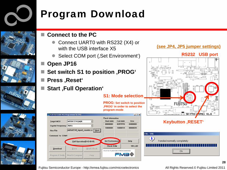
Connect to the PC Connect UART0 with RS232 (X4) orwith the USB interface X5Select COM port (‚Set Environment‘)
Open JP16Set switch S1 to position ‚PROG‘Press ‚Reset‘Start ‚Full Operation‘
Program Download
28
(see JP4, JP5 jumper settings)
RS232 USB port
S1: Mode selectionPROG: Set switch to position ‚PROG‘ in order to select the program-mode
Keybutton ‚RESET‘
All Rights Reserved.© Fujitsu Limited 2011

Fujitsu Semiconductor Europe - http://emea.fujitsu.com/microelectronics
Close the FUJITSU FLASH MCU ProgrammerSet switch S1 to position ‚RUN‘Press ‚Reset‘
Program Download
29
S1: Mode selectionRUN: Set switch to position ‚RUN‘in order to select the run-mode
Keybutton ‚RESET‘
Close the FUJITSU FLASH MCU Programmer
All Rights Reserved.© Fujitsu Limited 2011
Fujitsu Semiconductor Europe - http://emea.fujitsu.com/microelectronics
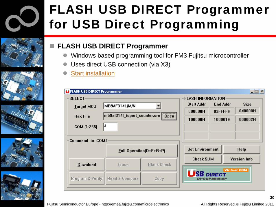
FLASH USB DIRECT Programmerfor USB Direct Programming
All Rights Reserved.© Fujitsu Limited 2011
30
FLASH USB DIRECT ProgrammerWindows based programming tool for FM3 Fujitsu microcontrollerUses direct USB connection (via X3)Start installation
Fujitsu Semiconductor Europe - http://emea.fujitsu.com/microelectronics
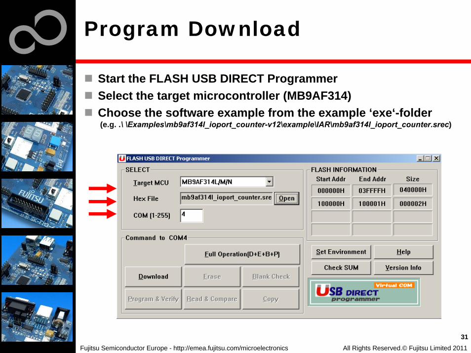
Program Download
All Rights Reserved.© Fujitsu Limited 2011
31
Start the FLASH USB DIRECT ProgrammerSelect the target microcontroller (MB9AF314)Choose the software example from the example ‘exe‘-folder (e.g. .\ \Examples\mb9af314l_ioport_counter-v12\example\IAR\mb9af314l_ioport_counter.srec)

Fujitsu Semiconductor Europe - http://emea.fujitsu.com/microelectronics
Select the MCU power supply (J5)Close JP16Set switch S1 to position ‚PROG‘Connect USB port X3 with the PC Install the USB driver
The driver is in the subfolder ‚driver‘ of installedprogrammerE.g.: C:\FUJITSU USB DIRECT Programmer
Select the COM port Press ‚Reset‘Start ‚Full Operation‘
Program Download
All Rights Reserved.© Fujitsu Limited 2011
32
Keybutton
‚RESET‘
USB port X3 J5
JP16
S1: Mode selectionPROG: Set switch to position ‚PROG‘ in order to select the program-mode

Fujitsu Semiconductor Europe - http://emea.fujitsu.com/microelectronics
Close the FLASH USB DIRECT ProgrammerSet switch S1 to position ‚RUN‘Press ‚Reset‘
Program Download
All Rights Reserved.© Fujitsu Limited 2011
33
Close the FLASH USB DIRECT Programmer
S1: Mode selectionRUN: Set switch to position ‚RUN‘in order to select the run-mode
Keybutton ‚RESET‘

Fujitsu Semiconductor Europe - http://emea.fujitsu.com/microelectronics
The MB9AF314L microcontroller offers a JTAG-Interfacethat is supported by SK-FM3-64PMC1.
Debug your program with a JTAG-Adapter e.g. Segger J-LinkConnect the J-Link to the JTAG-Interface routed to the 20-Pin-Header on X13 and to the USB-Port of your PCUse IAR-Embedded Workbench to debug your program If the JTAG-Adaper allows powering the target, then jumper J5 can be set as follows:
Debugging via JTAG
All Rights Reserved.© Fujitsu Limited 2011
34

Fujitsu Semiconductor Europe - http://emea.fujitsu.com/microelectronics
Debugging via TRACE
The MB9AF314LPMC microcontroller offers an ETM (Embedded-Trace-Macrocell) that is supported by SK-FM3-64PMC1
An optional JTAG-Adapter supporting trace features is required e.g. ULINKpro from KEILThe ETM is connected to the board with the JTAG adapter to the 20-Pin-Header X13 (JTAG)Use e.g. KEIL µVision to trace your program
All Rights Reserved.© Fujitsu Limited 2011
35

Fujitsu Semiconductor Europe - http://emea.fujitsu.com/microelectronics
IAR-Embedded Workbench /KEIL µVision IDE and Debugger
InstallationGetting StartedOpen ProjectBuild ProjectDebug Project
All Rights Reserved.© Fujitsu Limited 2011
36

Fujitsu Semiconductor Europe - http://emea.fujitsu.com/microelectronics
IAR Workbench Getting Started
Install EWARM from IAR-CD or download latest version from IAR Website
EWARM 30-day Evaluation Version• http://supp.iar.com/Download/SW/?item=EWARM-EVAL
EWARM 32K Kickstart Version• http://supp.iar.com/Download/SW/?item=EWARM-KS32
Install J-Link Debugger (SK-FM3-64PMC1-JLINK)Connect J-Link to USB Port and follow installation instructions
• Drivers:<Installation_Path>\IAR Systems\Embedded Workbench x.y\arm\drivers\Jlink\ x64 or x86
Start EWARM Workbench
All Rights Reserved.© Fujitsu Limited 2011
37

Fujitsu Semiconductor Europe - http://emea.fujitsu.com/microelectronics
IAR Workbench Getting Started
All Rights Reserved.© Fujitsu Limited 2011
38
Choose File → Open → WorkspaceSelect e.g.\ \Examples\mb9af314l_ioport_counter-v12\example\IAR\mb9af314l_ioport_counter.eww

Fujitsu Semiconductor Europe - http://emea.fujitsu.com/microelectronics
IAR Workbench – Main Window
All Rights Reserved.© Fujitsu Limited 2011
39
IAR WorkbenchWorkspace on left sideof Workbench window
• Choose:View→Workspace,if hidden
• Open main.c on source files.
Source files on rightside of Workbenchwindow as tabbedwindows
Project canalternatively beopened by:File→Open→Workspace→*.eww
Fujitsu Semiconductor Europe - http://emea.fujitsu.com/microelectronics
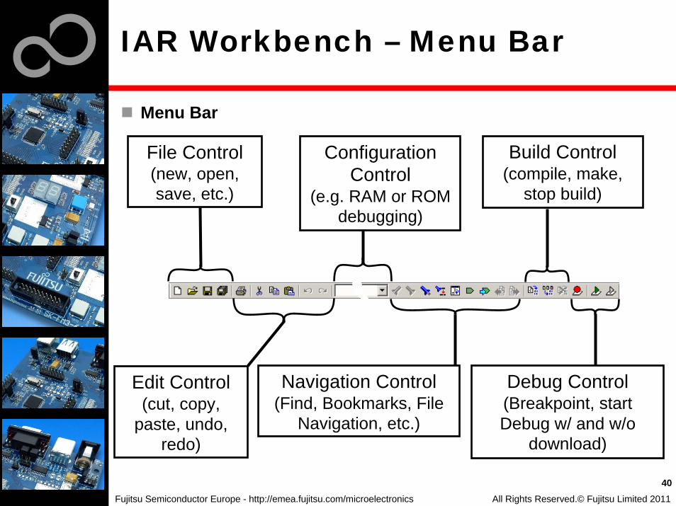
IAR Workbench – Menu Bar
Menu Bar
All Rights Reserved.© Fujitsu Limited 2011
40
File Control (new, open, save, etc.)
Edit Control(cut, copy,
paste, undo, redo)
Configuration Control
(e.g. RAM or ROM debugging)
Navigation Control(Find, Bookmarks, File
Navigation, etc.)
Build Control(compile, make,
stop build)
Debug Control(Breakpoint, start Debug w/ and w/o
download)
Fujitsu Semiconductor Europe - http://emea.fujitsu.com/microelectronics
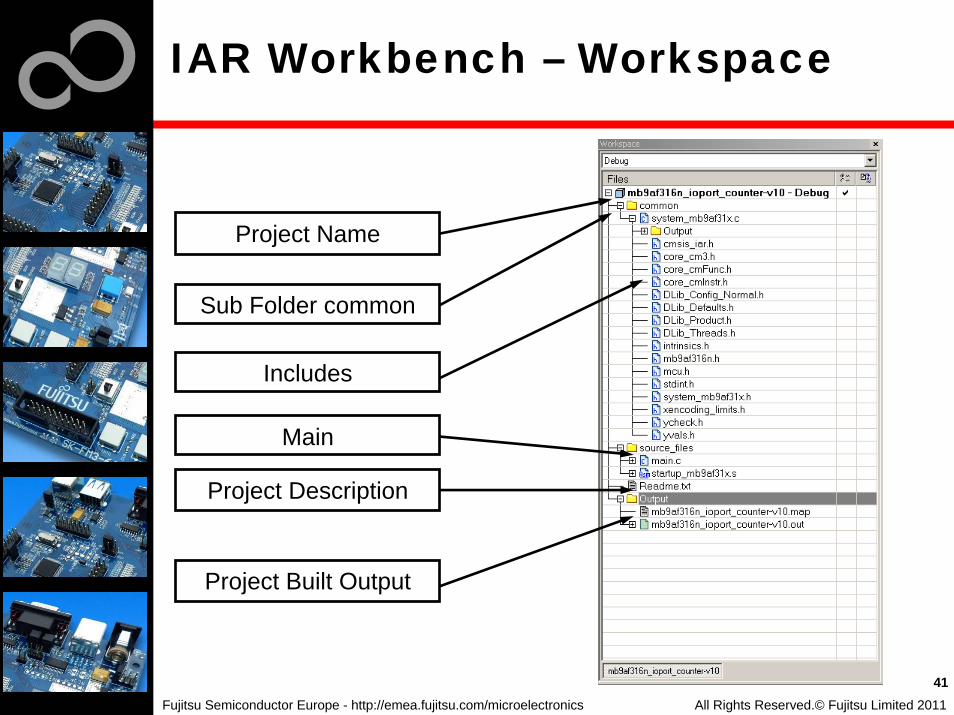
IAR Workbench – Workspace
All Rights Reserved.© Fujitsu Limited 2011
41
Project Name
Sub Folder common
Main
Includes
Project Description
Project Built Output

Fujitsu Semiconductor Europe - http://emea.fujitsu.com/microelectronics
IAR Workbench – Making Project
Making the ProjectUse Make-Icon ( ), <F7> orMenu: Project→MakeCheck for no errors in Output windowbelow
Build errors are indicated by orIn Output window and Source view
42All Rights Reserved.© Fujitsu Limited 2011

Fujitsu Semiconductor Europe - http://emea.fujitsu.com/microelectronics
IAR Workbench – Download to Target
Download to Target and Start DebuggingUse Icon, <Ctrl>-D, or Project→Download and DebugA new menu bar will occur on sucessful connection to target
43All Rights Reserved.© Fujitsu Limited 2011
Reset Target
Stop
Step Over
Step Into
Step Out
Next Statement
Run to Cursor
Run
End Debugging
Trace Control

Fujitsu Semiconductor Europe - http://emea.fujitsu.com/microelectronics
IAR Workbench – Debug (1)
Source WindowThe Source windows do not change contents but get additional information
• Current line (PC):• Halted on Breakpoint:• Halted on Data break (example):
Disassembly WindowShows ‘pure‘ disassebly viewShows mixed mode view
44All Rights Reserved.© Fujitsu Limited 2011

Fujitsu Semiconductor Europe - http://emea.fujitsu.com/microelectronics
IAR Workbench – Debug (2)
Watch WindowWatch
• Expressions/Variables have to be added by user and are updated by Halt/Breakpoint
Quick Watch• The Quick watch allows the user to calculate and recalculate
expressions even with variables
• The drop down menu memorizes the last typed contents
45All Rights Reserved.© Fujitsu Limited 2011
Fujitsu Semiconductor Europe - http://emea.fujitsu.com/microelectronics
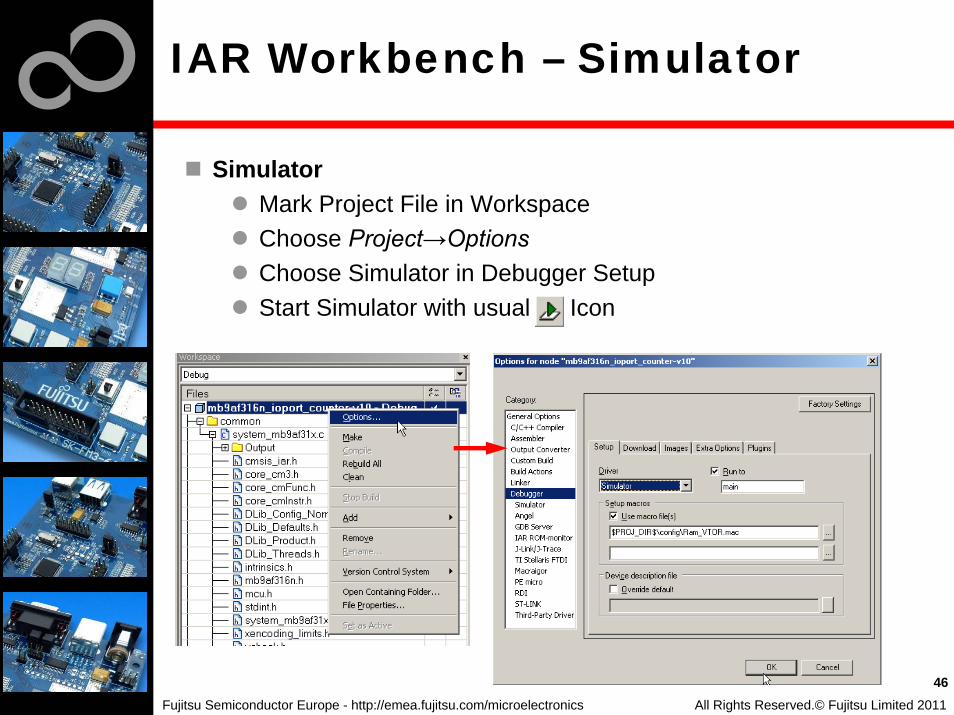
IAR Workbench – Simulator
SimulatorMark Project File in WorkspaceChoose Project→OptionsChoose Simulator in Debugger SetupStart Simulator with usual Icon
All Rights Reserved.© Fujitsu Limited 2011
46

Fujitsu Semiconductor Europe - http://emea.fujitsu.com/microelectronics
KEIL µVision IDE and Debugger Getting Started
Install µVision from KEIL-CD or download latest version from KEIL Website
Evalualtion Version• https://www.keil.com/demo/eval/arm.htm• Registration required
Install ULINK-ME Special installation is not needed, because ULINK-ME acts as a USB Human Interface Device (HID) and thus needs no extra USB driver
Install ULINK Pro (optional)ULINK Pro needs an own dedicated USB driver located in:<Installation Path>\KEIL\ARM\ULINK
Start µVision
All Rights Reserved.© Fujitsu Limited 2011
47

Fujitsu Semiconductor Europe - http://emea.fujitsu.com/microelectronics
KEIL µVision – Getting Started
Choose Menu: Project→Open Project...Browse to: Examples\mb9af314l_ioport_counter-v10\example\ARM\Choose mb9af314l_ioport_counter-v10.uvproj
All Rights Reserved.© Fujitsu Limited 2011
48

Fujitsu Semiconductor Europe - http://emea.fujitsu.com/microelectronics
KEIL µVision – Main Window
KEIL µVisionProject window on left side ofIDE window
• Choose:View→Project Windowif hidden
Source files on left sideof IDE window as tabbedwindowsOutput window on bottomside of IDE window
49All Rights Reserved.© Fujitsu Limited 2011

Fujitsu Semiconductor Europe - http://emea.fujitsu.com/microelectronics
KEIL µVision – Menu Bars (1)
Menu Bar 1Can be moved in bar window area or set floating
All Rights Reserved.© Fujitsu Limited 2011
50
File Control(new, open, save, etc.)
Edit Control(cut, copy, paste, etc)
(indention, commenting)
Navigation Control(Bookmarks + search, etc.)
(Text search, search in files, etc.)
Debug Control(Start/Stop Debug Session,
set/remove/disable breakpoints, remove/disable
all breakpoints)
Project Window View
IDE Configuration
Fujitsu Semiconductor Europe - http://emea.fujitsu.com/microelectronics
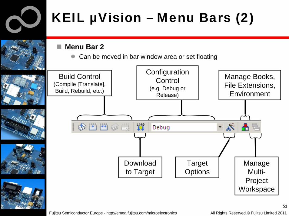
KEIL µVision – Menu Bars (2)
Menu Bar 2Can be moved in bar window area or set floating
All Rights Reserved.© Fujitsu Limited 2011
51
Build Control(Compile [Translate], Build, Rebuild, etc.)
Download to Target
Configuration Control
(e.g. Debug or Release)
Target Options
Manage Books, File Extensions,
Environment
Manage Multi-
Project Workspace
Fujitsu Semiconductor Europe - http://emea.fujitsu.com/microelectronics
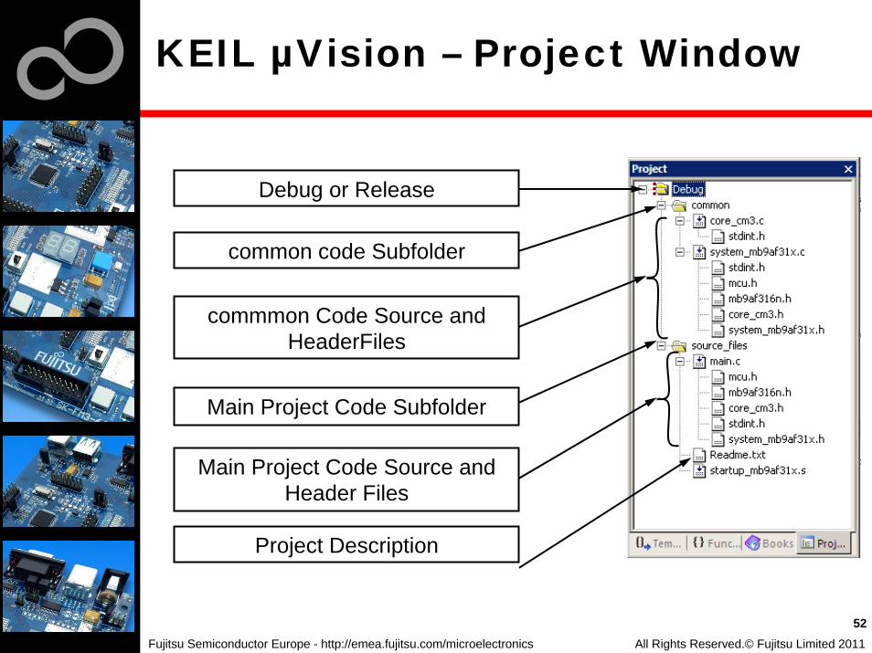
KEIL µVision – Project Window
All Rights Reserved.© Fujitsu Limited 2011
52
Debug or Release
common code Subfolder
commmon Code Source and HeaderFiles
Main Project Code Subfolder
Main Project Code Source and Header Files
Project Description
Fujitsu Semiconductor Europe - http://emea.fujitsu.com/microelectronics
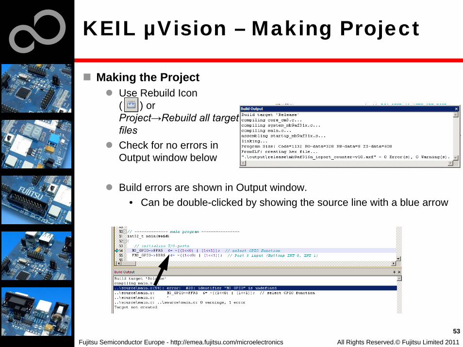
KEIL µVision – Making Project
Making the ProjectUse Rebuild Icon( ) orProject→Rebuild all targetfilesCheck for no errors inOutput window below
Build errors are shown in Output window.• Can be double-clicked by showing the source line with a blue arrow
53All Rights Reserved.© Fujitsu Limited 2011

Fujitsu Semiconductor Europe - http://emea.fujitsu.com/microelectronics
KEIL µVision – Debug (1)
Start DebuggingDownload to target first, when MCU Flash does not contain the current application openend and built in the IDE
• Use Download Icon ( ) or Menu: Flash→DownloadStart Debug Session
• Use Start/Stop Debug Icon ( ) or Menu: Debug→Start/Stop Debug Session
Ending Debug Session• Use same button as for starting debug session
54All Rights Reserved.© Fujitsu Limited 2011
Fujitsu Semiconductor Europe - http://emea.fujitsu.com/microelectronics
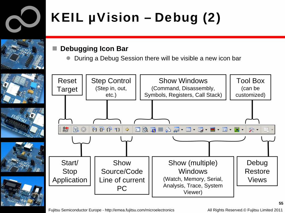
KEIL µVision – Debug (2)
Debugging Icon BarDuring a Debug Session there will be visible a new icon bar
All Rights Reserved.© Fujitsu Limited 2011
55
Reset Target
Start/Stop
Application
Step Control (Step in, out,
etc.)
Show Source/Code Line of current
PC
Show Windows (Command, Disassembly,
Symbols, Registers, Call Stack)
Show (multiple) Windows
(Watch, Memory, Serial, Analysis, Trace, System
Viewer)
Tool Box (can be
customized)
Debug Restore Views

Fujitsu Semiconductor Europe - http://emea.fujitsu.com/microelectronics
KEIL µVision – Debug (3)
Source ViewThe Source windows do not change contents but get additional information
All Rights Reserved.© Fujitsu Limited 2011
56
Active Breakpoint
Disabled Breakpoint
Current Program Counter
Current Cursor Line of Source Code
Code Lines with compiled Instructions
(dark grey )
Fujitsu Semiconductor Europe - http://emea.fujitsu.com/microelectronics
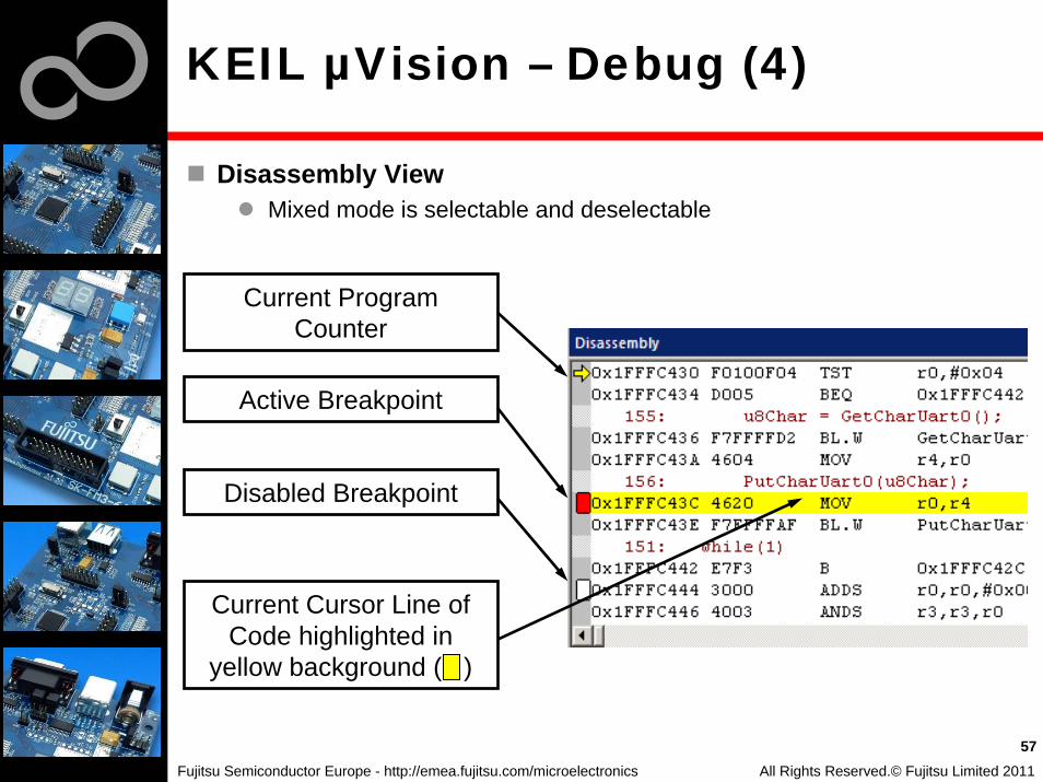
KEIL µVision – Debug (4)
Disassembly ViewMixed mode is selectable and deselectable
All Rights Reserved.© Fujitsu Limited 2011
57
Active Breakpoint
Disabled Breakpoint
Current Program Counter
Current Cursor Line of Code highlighted in
yellow background ( )

Fujitsu Semiconductor Europe - http://emea.fujitsu.com/microelectronics
KEIL µVision – Debug (5)
Memory WindowUp to 4 Memory windows can be displayed in tabsMemory is updated during runtimeMemory window tabs are shared with Watch windows
Register ViewRegister view is a tab of the Project windowChanges are highlighted in dark blue textbackgroundRegister tree knots can be expanded
58All Rights Reserved.© Fujitsu Limited 2011

Fujitsu Semiconductor Europe - http://emea.fujitsu.com/microelectronics
KEIL µVision – Debug (6)
Variable WindowsWatch Windows
• Up to 2 Watch windows are sharing their tabs with e.g. Memory and Local views
• Updated during runtime• Any changes are highlighted in dark blue text backround color• Displayed values can be changed by user during break
Local View• The local view shares the tab with e.g. Memory and Watch windows• Any changes are highlighted in dark blue text backround color• Displayed values can be changed by user during break
59All Rights Reserved.© Fujitsu Limited 2011

Fujitsu Semiconductor Europe - http://emea.fujitsu.com/microelectronics
KEIL µVision – Simulator
SimulatorThe Core Simulator can be selected by the menu:Flash→Configure Flash Tools... and then choosing Use SimulatorLook & feel is like using ULINK debuggerControlable also with *.ini files
All Rights Reserved.© Fujitsu Limited 2011
60
Fujitsu Semiconductor Europe - http://emea.fujitsu.com/microelectronics
Further Steps
In order to learn more about Fujitsu’s microcontrollers
Visit our microcontroller website• http://mcu.emea.fujitsu.com• http://mcu.emea.fujitsu.com/mcu_product/detail/MB9AF314LPMC1.htm
See our application notes• http://mcu.emea.fujitsu.com/mcu_product/mcu_all_appnotes.htm
See our software examples• http://mcu.emea.fujitsu.com/mcu_product/mcu_all_software.htm
Contact your local distributor …
for individual supportto register for our monthly FM3 seminar to order the latest ‘Fujitsu Micros DVD’ containing all information regarding Fujitsu’s 8-bit, 16-bit, and 32-bit microcontrollers
61All Rights Reserved.© Fujitsu Limited 2011
Fujitsu Semiconductor Europe - http://emea.fujitsu.com/microelectronics
Contacts - Distribution
European distributors
Anatec www.anatec.chEBV Elektronik www.ebv.comFarnell www.farnell.comGlyn www.glyn.de , www.glyn.chIneltek www.ineltek.comMelchioni Electronica www.melchioni.itPN Electronics www.pne.frRutronik Elektronische www.rutronik.comBauelemente
62All Rights Reserved.© Fujitsu Limited 2011

Fujitsu Semiconductor Europe - http://emea.fujitsu.com/microelectronics
Fujitsu Semiconductor Europe
http://www.fujitsu.com/emea/contact/microelectronics/salesoffices/
Germany (Headquarters)63225 Langen Tel: +49 (0) 61 03 69 00
France91300 Massy Tel: +33 (0) 1 64 47 97 00
Italy20080 Milano Tel: +39 02 90 45 02 1
United Kingdom Maidenhead Tel: +44 (0) 1628 50 46 00
Hungary1143 Budapest Tel: +36 1 471 21 29
Turkey34180 Istanbul Tel: +90 212 557 18 81
World Wide Webhttp://emea.fujitsu.com/microelectronicshttp://mcu.emea.fujitsu.comContact: [email protected]
63All Rights Reserved.© Fujitsu Limited 2011

Fujitsu Semiconductor Europe - http://emea.fujitsu.com/microelectronics
EU-Konformitätserklärung /EU declaration of conformity
Hiermit erklären wir, Fujitsu Semiconductor Europe GmbH, Pittlerstrasse 47, 63225 Langen, Germanydass dieses Board aufgrund seiner Konzipierung und Bauart sowie in den von uns in Verkehr gebrachten Ausführung(en) den grundlegenden Anforderungen der EU-Richtlinie 2004/108/EC „Elektromagnetische Verträglichkeit“entspricht. Durch eine Veränderung des Boards (Hard- und/ oder Software) verliert diese Erklärung ihre Gültigkeit!
We, Fujitsu Semiconductor Europe GmbH, Pittlerstrasse 47, 63225 Langen, Germany hereby declare that the design, construction and description circulated by us of this boardcomplies with the appropriate basic safety and health requirements according to the EU Guideline 2004/108/EC entitled ’Electro-Magnetic Compatibility’. Any changes to the equipment (hardware and/ or software) will render this declaration invalid!
Note:All data and power supply lines connected to this starter kit should be kept as short as possible, with a maximum allowable length of 3m. Shielded cables should be used for data lines. As a rule of thumb, the cable length used when connecting external circuitry to the MCU pin header connectors for example should be less than 20cm. Longer cablesmay affect EMC performance and cause radio interference.
All Rights Reserved.© Fujitsu Limited 2010
64

Fujitsu Semiconductor Europe - http://emea.fujitsu.com/microelectronics
Recycling
Gültig für EU-Länder:Gemäß der Europäischen WEEE-Richtlinie und deren Umsetzung in landesspezifische Gesetze nehmen wir dieses Gerät wieder zurück.Zur Entsorgung schicken Sie das Gerät bitte an die folgende Adresse:
Valid for European Union Countries:According to the European WEEE-Directive and its implementation into national laws we take this device back.For disposal please send the device to the following address:
Fujitsu Semiconductor Europe GmbHWarehouse/Disposal
Monzastraße 4aD-63225 Langen
This board is compliant with China RoHS
65All Rights Reserved.© Fujitsu Limited 2011

Fujitsu Semiconductor Europe - http://emea.fujitsu.com/microelectronics
CD Contents
SoftwareFUJITSU FLASH MCU ProgrammerFLASH USB DIRECT ProgrammerSerialPortViewerAndTerminal
DocumentsSchematic ‘SK-FM3-64PMC1’Data sheet MB9A310SeriesPeripheral Manual
Errata sheet Technical Reference ManualFlash Programming Manual
Download the latest version from the following website:http://mcu.emea.fujitsu.com
66
ExamplesMB9AF314LPMC_templateFurther examples are available on the CD and on our website
Note: Please copy the examples to your local drive!
All Rights Reserved.© Fujitsu Limited 2011


