34
SKF ball bearing units UC range Japanese Industrial Standards compliant ball bearing units
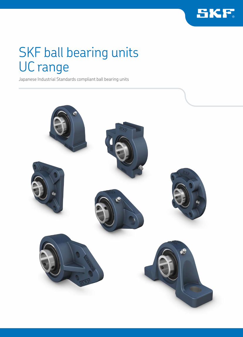
SKF ball bearing unitsUC rangeJapanese Industrial Standards compliant ball bearing units
Main applications include
• Material handling conveyors• Agriculture machinery• Food & beverage machinery• Packaging equipment• Fitness equipment• Air handling
Other industries
• Textile machinery• Construction machinery• Escalators• Metal industry
Solid design, solid benefits
In order to meet the industry’s demands of improved protection against contaminant ingress, better shaft balance and locking strength, we have now developed a new range of ball bearing units – the UC range.
These bearing units offer optimized protection against contaminants as well as better resistance against washdowns. In addition, the units are designed with a 120° grub screw angle locking system to operate reliably in applications where good shaft balance is needed and where systemic vibration is a characteristic application condition.
Easy to order, easy to replace
You want a solution that makes your life easy – a solution with inter-changeable boundary dimensions, housing configurations and part numbers. The UC range ball bearing units achieve this and more. It’s compatible with JIS* housings available today on the market. No modi-fication of your machine is needed. The dimensions meet most of the current UC designated bearing unit fitting requirements. And whatever product you need, with SKF you know it will be easy to obtain, straight-forward to install and manufactured to SKF quality levels.
* JIS: Japanese Industrial Standards
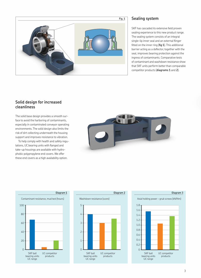
Fig. 1
Solid design for increased cleanliness
The solid base design provides a smooth sur-face to avoid the harboring of contaminants, especially in contaminated conveyor operating environments. The solid design also limits the risk of dirt collecting underneath the housing support and improves resistance to vibration.
To help comply with health and safety regu-lations, UC bearing units with flanged and take-up housings are available with hydro-phobic polypropylene end covers. We offer these end covers as a high availability option.
100
80
60
40
20
0
5
4
3
2
1
0
1.8
1.6
1.4
1.2
1.0
0.8
0.6
0.4
0.2
0
Contaminant resistance, mud test (hours) Washdown resistance (score) Axial holding power – grub screws (kN/Nm)
Diagram 1 Diagram 2 Diagram 3
UC competitor products
UC competitor products
UC competitor products
SKF ball bearing units
UC range
SKF ball bearing units
UC range
SKF ball bearing units
UC range
Sealing system
SKF has cascaded its extensive field proven sealing experience to this new product range. The sealing system consists of an integral single- lip inner seal and an external flinger fitted on the inner ring (fig 1). This additional barrier acting as a deflector, together with the seal, improves bearing protection against the ingress of contaminants. Comparative tests of contaminant and washdown resistance show that SKF units perform better than comparable competitor products (diagrams 1 and 2).
3
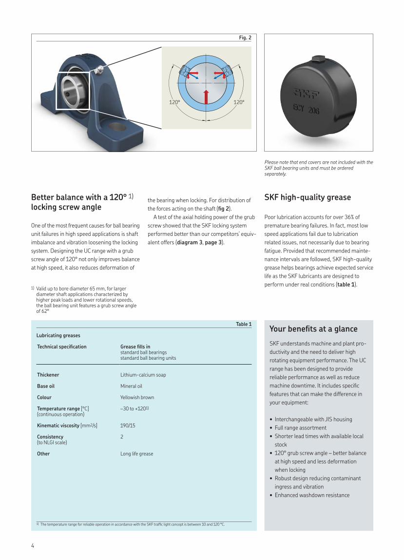
Better balance with a 120° 1) locking screw angle
One of the most frequent causes for ball bearing unit failures in high speed applications is shaft imbalance and vibration loosening the locking system. Designing the UC range with a grub screw angle of 120° not only improves balance at high speed, it also reduces deformation of
Table 1
Lubricating greases
Technical specification Grease fills instandard ball bearings
standard ball bearing units
Thickener Lithium-calcium soap
Base oil Mineral oil
Colour Yellowish brown
Temperature range [°C](continuous operation)
–30 to +1201)
Kinematic viscosity [mm2/s] 190/15
Consistency (to NLGI scale)
2
Other Long life grease
1) The temperature range for reliable operation in accordance with the SKF traffic light concept is between 10 and 120 °C.
SKF high-quality grease
Poor lubrication accounts for over 36% of premature bearing failures. In fact, most low speed applications fail due to lubrication related issues, not necessarily due to bearing fatigue. Provided that recommended mainte-nance intervals are followed, SKF high-quality grease helps bearings achieve expected service life as the SKF lubricants are designed to perform under real conditions (table 1).
Please note that end covers are not included with the SKF ball bearing units and must be ordered separately.
Your benefits at a glanceSKF understands machine and plant pro-ductivity and the need to deliver high rotating equipment performance. The UC range has been designed to provide reliable performance as well as reduce machine downtime. It includes specific features that can make the difference in your equipment:
• Interchangeable with JIS housing• Full range assortment• Shorter lead times with available local
stock• 120° grub screw angle – better balance
at high speed and less deformation when locking
• Robust design reducing contaminant ingress and vibration
• Enhanced washdown resistance
Fig. 2
120° 120°
the bearing when locking. For distribution of the forces acting on the shaft (fig 2).
A test of the axial holding power of the grub screw showed that the SKF locking system performed better than our competitors’ equiv-alent offers (diagram 3, page 3).
1) Valid up to bore diameter 65 mm, for larger diameter shaft applications characterized by higher peak loads and lower rotational speeds, the ball bearing unit features a grub screw angle of 62°
4
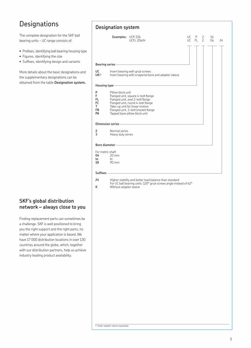
Designation systemExamples: UCP 216 UC P 2 16
UCFL 204/H UC FL 2 04 /H
Bearing series
UC Insert bearing with grub screwsUK1) Insert bearing with a tapered bore and adapter sleeve
Housing type
P Pillow block unitF Flanged unit, square 4-bolt flange FL Flanged unit, oval 2-bolt flangeFC Flanged unit, round 4-bolt flangeT Take-up unit for linear motionFB Flanged unit, 3-bolt bracket flangePA Tapped base pillow block unit
Dimension series
2 Normal series3 Heavy duty series
Bore diameter
For metric shaft04 20 mmto to18 90 mm
Suffixes
/H Higher stability and better load balance than standardFor UC ball bearing units: 120° grub screws angle instead of 62°
K Without adapter sleeve
1) Order adapter sleeve separately.
DesignationsThe complete designation for the SKF ball bearing units – UC range consists of:
• Prefixes, identifying ball bearing housing type• Figures, identifying the size• Suffixes, identifying design and variants
More details about the basic designations and the supplementary designations can be obtained from the table Designation system.
SKF’s global distribution network – always close to you
Finding replacement parts can sometimes be a challenge. SKF is well positioned to bring you the right support and the right parts, no matter where your application is based. We have 17 000 distribution locations in over 130 countries around the globe, which, together with our distribution partners, help us achieve industry leading product availability.
5
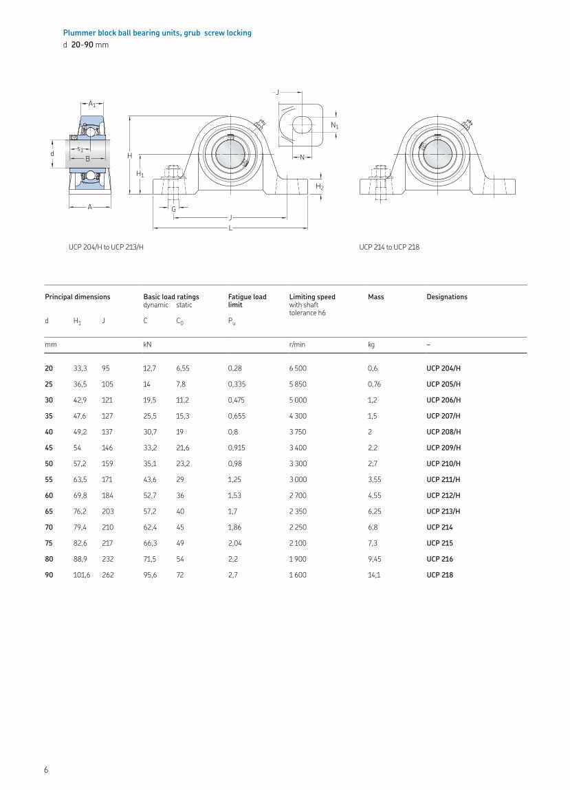
Plummer block ball bearing units, grub screw lockingd 20-90 mm
Principal dimensions Basic load ratings Fatigue load limit
Limiting speed Mass Designationsdynamic static with shaft
tolerance h6d H1 J C C0 Pu
mm kN r/min kg –
20 33,3 95 12,7 6,55 0,28 6 500 0,6 UCP 204/H
25 36,5 105 14 7,8 0,335 5 850 0,76 UCP 205/H
30 42,9 121 19,5 11,2 0,475 5 000 1,2 UCP 206/H
35 47,6 127 25,5 15,3 0,655 4 300 1,5 UCP 207/H
40 49,2 137 30,7 19 0,8 3 750 2 UCP 208/H
45 54 146 33,2 21,6 0,915 3 400 2,2 UCP 209/H
50 57,2 159 35,1 23,2 0,98 3 300 2,7 UCP 210/H
55 63,5 171 43,6 29 1,25 3 000 3,55 UCP 211/H
60 69,8 184 52,7 36 1,53 2 700 4,55 UCP 212/H
65 76,2 203 57,2 40 1,7 2 350 6,25 UCP 213/H
70 79,4 210 62,4 45 1,86 2 250 6,8 UCP 214
75 82,6 217 66,3 49 2,04 2 100 7,3 UCP 215
80 88,9 232 71,5 54 2,2 1 900 9,45 UCP 216
90 101,6 262 95,6 72 2,7 1 600 14,1 UCP 218
UCP 204/H to UCP 213/H
N1
N
JA1
A
d
H1H2
s1B H
JL
G
UCP 214 to UCP 218
6
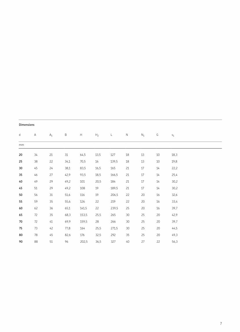
Dimensions
d A A1 B H H2 L N N1 G s1
mm
20 34 21 31 64,5 13,5 127 18 13 10 18,3
25 38 22 34,1 70,5 16 139,5 18 13 10 19,8
30 45 24 38,1 83,5 16,5 165 21 17 14 22,2
35 46 27 42,9 93,5 18,5 166,5 21 17 14 25,4
40 49 29 49,2 101 20,5 184 21 17 14 30,2
45 51 29 49,2 108 19 189,5 21 17 14 30,2
50 56 31 51,6 116 19 206,5 22 20 16 32,6
55 59 35 55,6 126 22 219 22 20 16 33,4
60 62 36 65,1 141,5 22 239,5 25 20 16 39,7
65 72 35 68,3 153,5 25,5 265 30 25 20 42,9
70 72 41 69,9 159,5 28 266 30 25 20 39,7
75 73 42 77,8 164 25,5 271,5 30 25 20 44,5
80 78 45 82,6 176 32,5 292 35 25 20 49,3
90 88 51 96 202,5 36,5 327 40 27 22 56,3
7
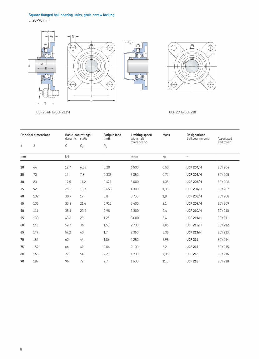
Square flanged ball bearing units, grub screw lockingd 20-90 mm
Principal dimensions Basic load ratings Fatigue load limit
Limiting speed Mass Designationsdynamic static with shaft
tolerance h6Ball bearing unit Associated
end coverd J C C0 Pu
mm kN r/min kg –
20 64 12,7 6,55 0,28 6 500 0,53 UCF 204/H ECY 204
25 70 14 7,8 0,335 5 850 0,72 UCF 205/H ECY 205
30 83 19,5 11,2 0,475 5 000 1,05 UCF 206/H ECY 206
35 92 25,5 15,3 0,655 4 300 1,35 UCF 207/H ECY 207
40 102 30,7 19 0,8 3 750 1,8 UCF 208/H ECY 208
45 105 33,2 21,6 0,915 3 400 2,1 UCF 209/H ECY 209
50 111 35,1 23,2 0,98 3 300 2,4 UCF 210/H ECY 210
55 130 43,6 29 1,25 3 000 3,4 UCF 211/H ECY 211
60 143 52,7 36 1,53 2 700 4,05 UCF 212/H ECY 212
65 149 57,2 40 1,7 2 350 5,35 UCF 213/H ECY 213
70 152 62 44 1,86 2 250 5,95 UCF 214 ECY 214
75 159 66 49 2,04 2 100 6,2 UCF 215 ECY 215
80 165 72 54 2,2 1 900 7,35 UCF 216 ECY 216
90 187 96 72 2,7 1 600 11,5 UCF 218 ECY 218
UCF 204/H to UCF 213/H
T
d
G
AA1
JL
N
Bs1
A5
UCF 214 to UCF 218
8
Dimensions
d A A1 A5 B L N G s1 T
mm
20 25,5 11 20,5 31 86 12 10 18,3 33,3
25 27 13 20,5 34,1 95 12 10 19,8 35,8
30 30 14 22,5 38,1 108 12 10 22,2 40,2
35 32 15 24,5 42,9 118 14 12 25,4 44,4
40 35,5 15 26 49,2 130 16 14 30,2 51,2
45 38 16 26,5 49,2 137 16 14 30,2 52,2
50 39,5 16 33 51,6 143 16 14 32,6 54,6
55 43 18 37,5 55,6 162 19 16 33,4 58,4
60 47,5 18 39 65,1 175 19 16 39,7 68,7
65 50 22 39 68,3 187 19 16 42,9 72,9
70 54 22 41,5 74,6 193 19 16 44,4 75,4
75 56,5 22 41,5 77,8 200 19 16 44,5 78,3
80 58 22 41,5 82,6 208 23 20 49,3 83,3
90 68,5 25 45,5 96 235 23 20 56,3 96
UCF 214 to UCF 218
9
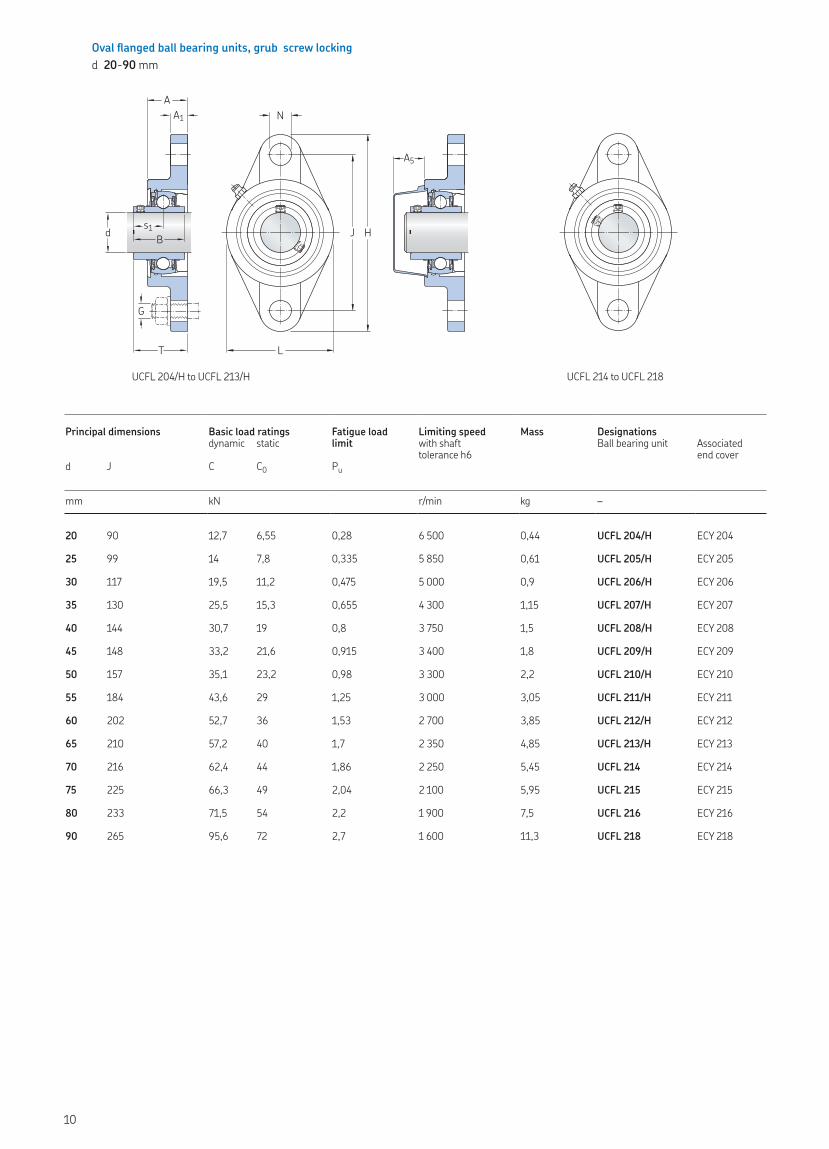
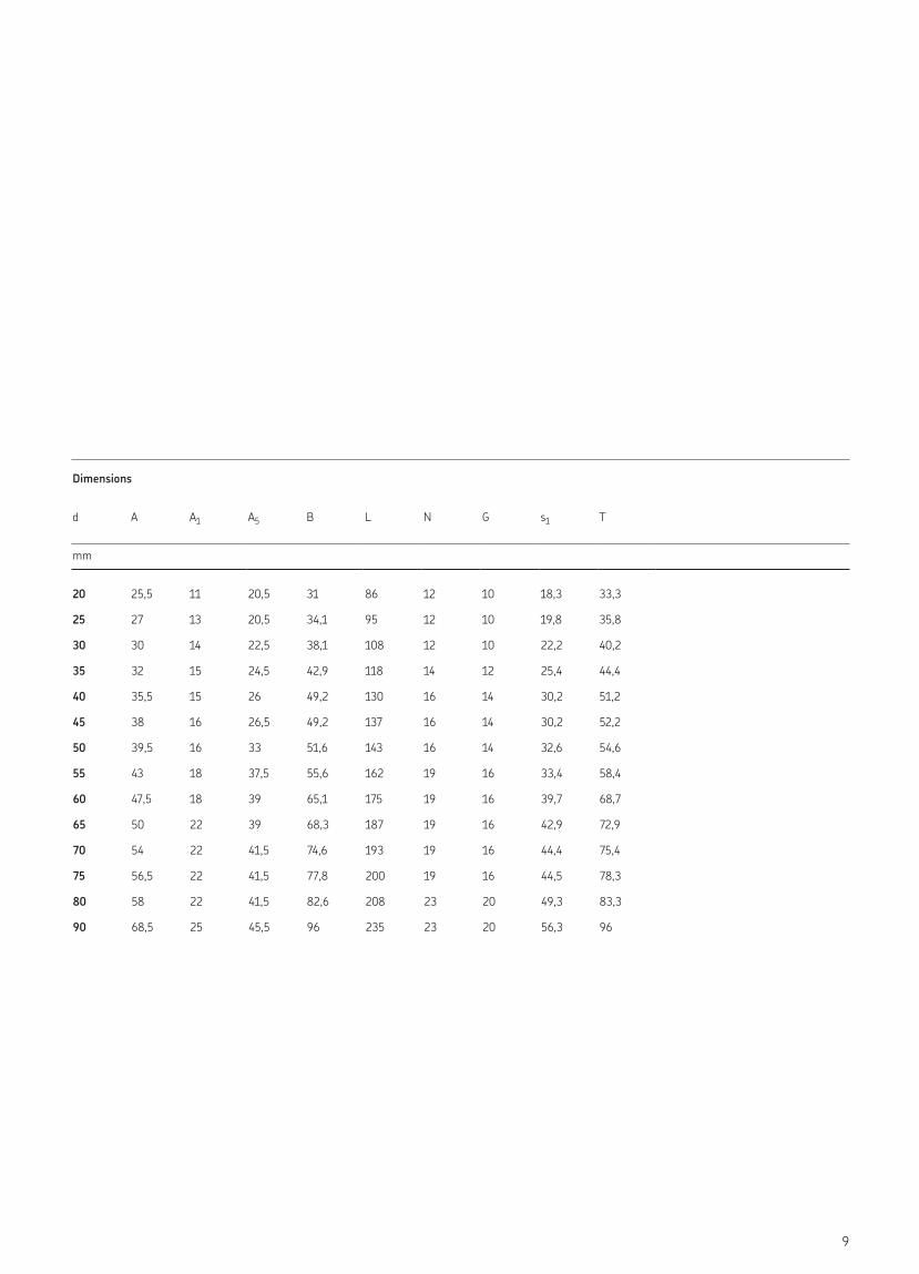
Oval flanged ball bearing units, grub screw lockingd 20-90 mm
Principal dimensions Basic load ratings Fatigue load limit
Limiting speed Mass Designationsdynamic static with shaft
tolerance h6Ball bearing unit Associated
end coverd J C C0 Pu
mm kN r/min kg –
20 90 12,7 6,55 0,28 6 500 0,44 UCFL 204/H ECY 204
25 99 14 7,8 0,335 5 850 0,61 UCFL 205/H ECY 205
30 117 19,5 11,2 0,475 5 000 0,9 UCFL 206/H ECY 206
35 130 25,5 15,3 0,655 4 300 1,15 UCFL 207/H ECY 207
40 144 30,7 19 0,8 3 750 1,5 UCFL 208/H ECY 208
45 148 33,2 21,6 0,915 3 400 1,8 UCFL 209/H ECY 209
50 157 35,1 23,2 0,98 3 300 2,2 UCFL 210/H ECY 210
55 184 43,6 29 1,25 3 000 3,05 UCFL 211/H ECY 211
60 202 52,7 36 1,53 2 700 3,85 UCFL 212/H ECY 212
65 210 57,2 40 1,7 2 350 4,85 UCFL 213/H ECY 213
70 216 62,4 44 1,86 2 250 5,45 UCFL 214 ECY 214
75 225 66,3 49 2,04 2 100 5,95 UCFL 215 ECY 215
80 233 71,5 54 2,2 1 900 7,5 UCFL 216 ECY 216
90 265 95,6 72 2,7 1 600 11,3 UCFL 218 ECY 218
UCFL 204/H to UCFL 213/H
d
AA1
T
G
N
L
J HBs1
A5
UCFL 214 to UCFL 218
10
Dimensions
d A A1 A5 B H L N G s1 T
mm
20 25,5 11 20,5 31 113 60 12 10 18,3 33,3
25 27 13 20,5 34,1 130 68 16 14 19,8 35,8
30 30 13 22,5 38,1 147,5 80 16 14 22,2 40,2
35 32 14 24,5 42,9 161 90 16 14 25,4 44,4
40 34 14 26 49,2 174,5 100 16 14 30,2 51,2
45 35 15 26,5 49,2 188 108 19 16 30,2 51,2
50 39 15 33 51,6 197 115 19 16 32,6 53,6
55 41,5 18 37,5 55,6 224 130 19 16 33,4 58,4
60 45 18 39 65,1 250 140 23 20 39,7 68,7
65 47 20 39 68,3 258 155 23 20 42,9 72,9
70 50 20 41,5 74,6 265 160 23 20 44,4 75,4
75 54 20 41,5 77,8 275 164 23 20 44,5 78,5
80 56 20 41,5 82,6 290 180 25 22 49,3 83,3
90 68 23 45,5 96 320 205 25 22 56,3 96,3
11
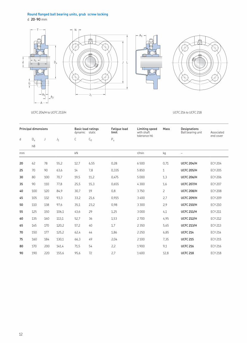
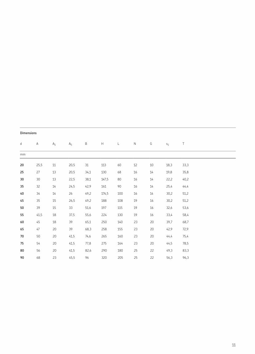
Round flanged ball bearing units, grub screw lockingd 20-90 mm
Principal dimensions Basic load ratings Fatigue load limit
Limiting speed Mass Designationsdynamic static with shaft
tolerance h6Ball bearing unit Associated
end coverd Da J J1 C C0 Pu
h8
mm kN r/min kg –
20 62 78 55,2 12,7 6,55 0,28 6 500 0,71 UCFC 204/H ECY 204
25 70 90 63,6 14 7,8 0,335 5 850 1 UCFC 205/H ECY 205
30 80 100 70,7 19,5 11,2 0,475 5 000 1,3 UCFC 206/H ECY 206
35 90 110 77,8 25,5 15,3 0,655 4 300 1,6 UCFC 207/H ECY 207
40 100 120 84,9 30,7 19 0,8 3 750 2 UCFC 208/H ECY 208
45 105 132 93,3 33,2 21,6 0,915 3 400 2,7 UCFC 209/H ECY 209
50 110 138 97,6 35,1 23,2 0,98 3 300 2,9 UCFC 210/H ECY 210
55 125 150 106,1 43,6 29 1,25 3 000 4,1 UCFC 211/H ECY 211
60 135 160 113,1 52,7 36 1,53 2 700 4,95 UCFC 212/H ECY 212
65 145 170 120,2 57,2 40 1,7 2 350 5,65 UCFC 213/H ECY 213
70 150 177 125,2 62,4 44 1,86 2 250 6,85 UCFC 214 ECY 214
75 160 184 130,1 66,3 49 2,04 2 100 7,35 UCFC 215 ECY 215
80 170 200 141,4 71,5 54 2,2 1 900 9,1 UCFC 216 ECY 216
90 190 220 155,6 95,6 72 2,7 1 600 12,8 UCFC 218 ECY 218
UCFC 204/H to UCFC 213/H UCFC 214 to UCFC 218
G
d Bs1
T
Da
A1 A3
A
N
J1
J L
A5
12
Dimensions
d A A1 A3 A5 B L N G s1 T
mm
20 26 7 5 20,5 31 100 12 10 18,3 28,3
25 27,5 7 6 20,5 34,1 115 12 10 19,8 29,8
30 30 8 8 22,5 38,1 125 12 10 22,2 32,2
35 32 9 8 24,5 42,9 135 14 12 25,4 36,4
40 35,5 9 10 26 49,2 145 14 12 30,2 41,2
45 37,5 14 12 26,5 49,2 160 16 14 30,2 40,2
50 39 14 12 33 51,6 165 16 14 32,6 42,6
55 43 15 12 37,5 55,6 185 19 16 33,4 46,4
60 47,5 15 12 39 65,1 195 19 16 39,7 56,7
65 50 15 14 39 68,3 205 19 16 42,9 58,9
70 54 10 14 41,5 74,6 215 19 16 44,4 61,4
75 56 10 16 41,5 77,8 220 19 16 44,5 62,5
80 58 10 16 41,5 82,6 240 23 20 49,3 67,3
90 68,5 20 18 45,5 96 265 23 20 56,3 78,3
13
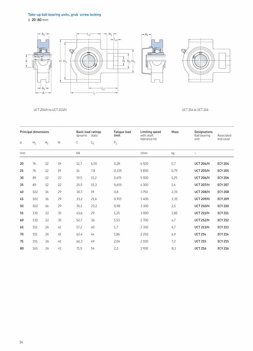
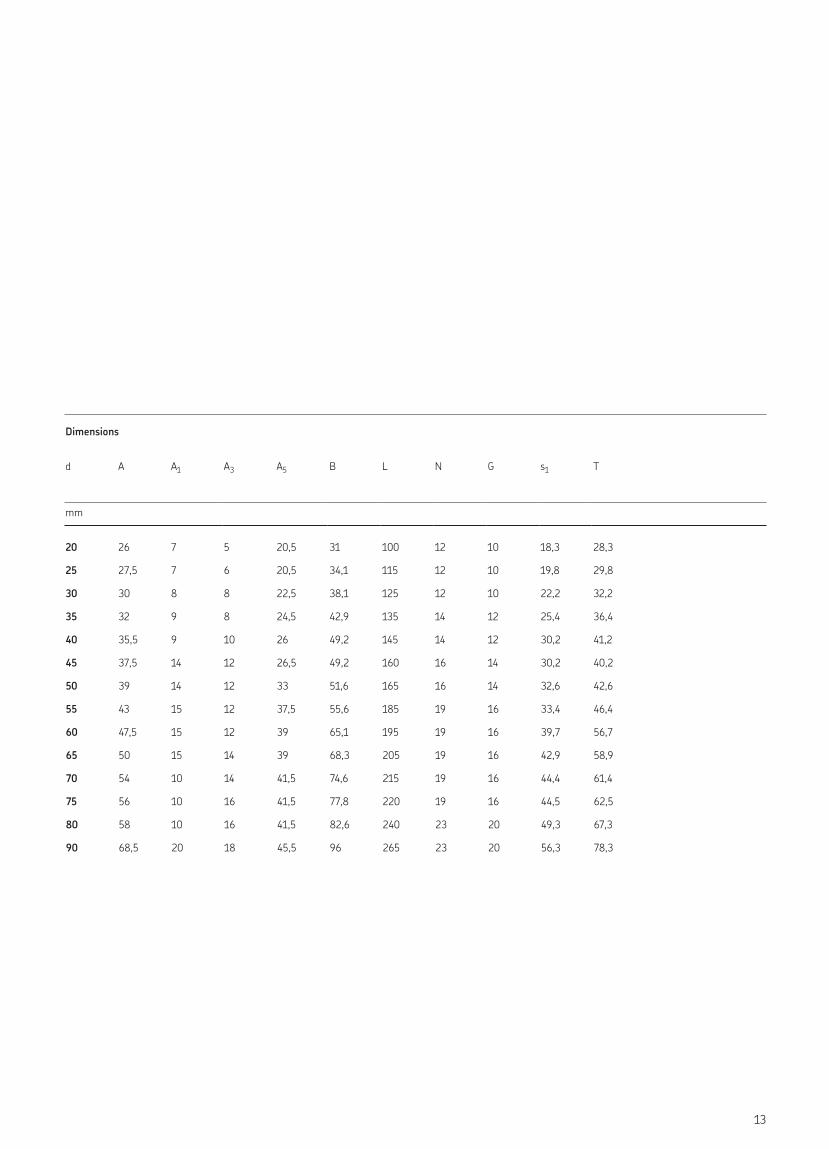
Take-up ball bearing units, grub screw lockingd 20-80 mm
Principal dimensions Basic load ratings Fatigue load limit
Limiting speed Mass Designationsdynamic static with shaft
tolerance h6Ball bearing unit
Associated end cover
d H1 A1 N C C0 Pu
mm kN r/min kg –
20 76 12 19 12,7 6,55 0,28 6 500 0,7 UCT 204/H ECY 204
25 76 12 19 14 7,8 0,335 5 850 0,79 UCT 205/H ECY 205
30 89 12 22 19,5 11,2 0,475 5 000 1,25 UCT 206/H ECY 206
35 89 12 22 25,5 15,3 0,655 4 300 1,6 UCT 207/H ECY 207
40 102 16 29 30,7 19 0,8 3 750 2,35 UCT 208/H ECY 208
45 102 16 29 33,2 21,6 0,915 3 400 2,35 UCT 209/H ECY 209
50 102 16 29 35,1 23,2 0,98 3 300 2,5 UCT 210/H ECY 210
55 130 22 35 43,6 29 1,25 3 000 3,85 UCT 211/H ECY 211
60 130 22 35 52,7 36 1,53 2 700 4,7 UCT 212/H ECY 212
65 151 26 41 57,2 40 1,7 2 350 6,7 UCT 213/H ECY 213
70 151 26 41 62,4 44 1,86 2 250 6,9 UCT 214 ECY 214
75 151 26 41 66,3 49 2,04 2 100 7,2 UCT 215 ECY 215
80 165 26 41 71,5 54 2,2 1 900 8,3 UCT 216 ECY 216
UCT 204/H to UCT 213/H
d
A1
A2
A
H H1 N H2
N1L2
N2
L1
L3
L
Bs1
A5
UCT 214 to UCT 216
14
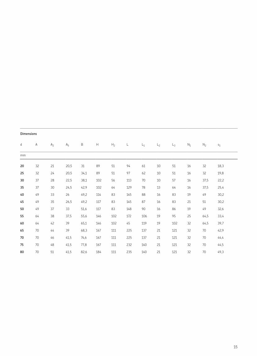
Dimensions
d A A2 A5 B H H2 L L1 L2 L3 N1 N2 s1
mm
20 32 21 20,5 31 89 51 94 61 10 51 16 32 18,3
25 32 24 20,5 34,1 89 51 97 62 10 51 16 32 19,8
30 37 28 22,5 38,1 102 56 113 70 10 57 16 37,5 22,2
35 37 30 24,5 42,9 102 64 129 78 13 64 16 37,5 25,4
40 49 33 26 49,2 114 83 145 88 16 83 19 49 30,2
45 49 35 26,5 49,2 117 83 145 87 16 83 21 51 30,2
50 49 37 33 51,6 117 83 148 90 16 86 19 49 32,6
55 64 38 37,5 55,6 146 102 172 106 19 95 25 64,5 33,4
60 64 42 39 65,1 146 102 45 119 19 102 32 64,5 39,7
65 70 44 39 68,3 167 111 225 137 21 121 32 70 42,9
70 70 46 41,5 74,6 167 111 225 137 21 121 32 70 44,4
75 70 48 41,5 77,8 167 111 232 140 21 121 32 70 44,5
80 70 51 41,5 82,6 184 111 235 140 21 121 32 70 49,3
15
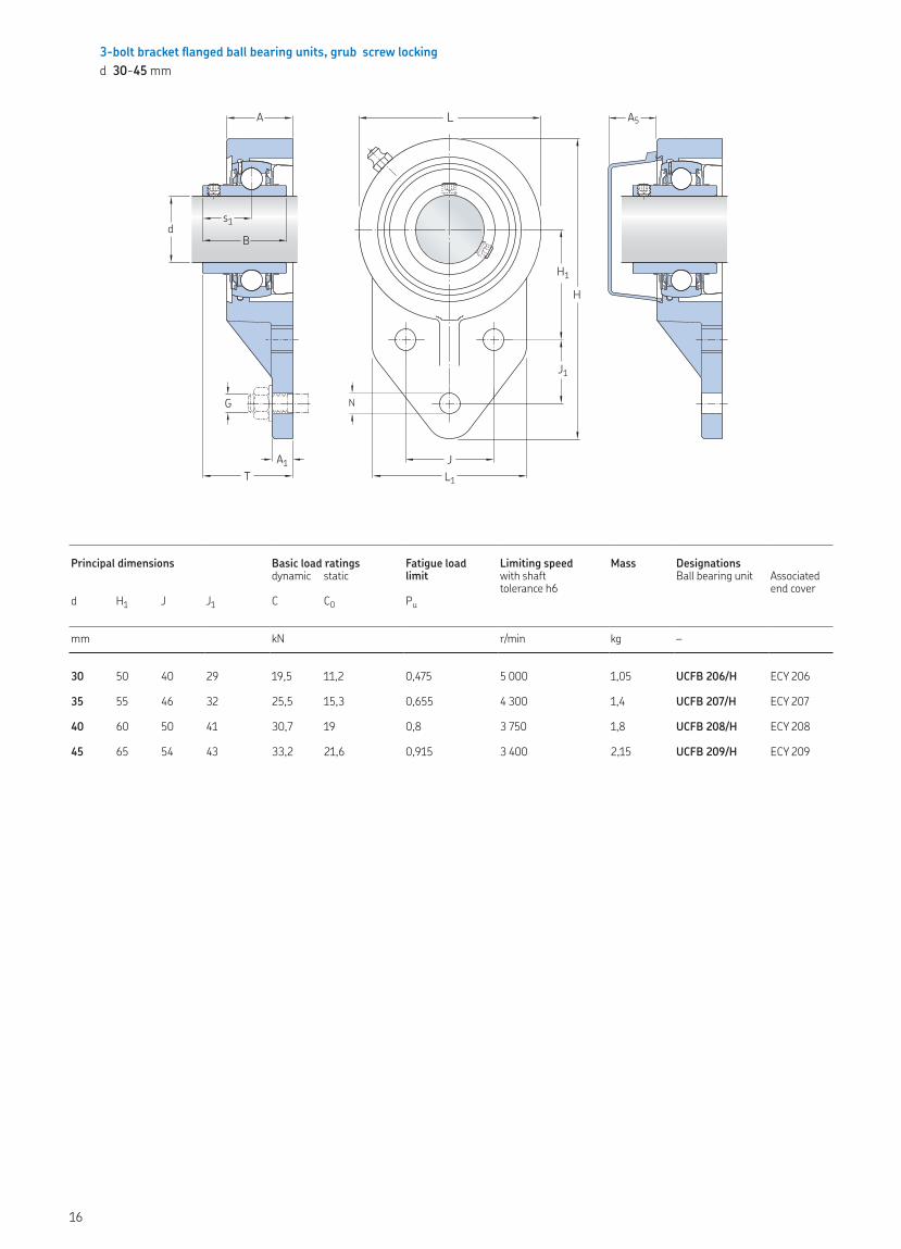
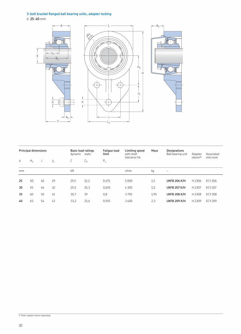
3-bolt bracket flanged ball bearing units, grub screw lockingd 30-45 mm
Principal dimensions Basic load ratings Fatigue load limit
Limiting speed Mass Designations dynamic static with shaft
tolerance h6Ball bearing unit Associated
end coverd H1 J J1 C C0 Pu
mm kN r/min kg –
30 50 40 29 19,5 11,2 0,475 5 000 1,05 UCFB 206/H ECY 206
35 55 46 32 25,5 15,3 0,655 4 300 1,4 UCFB 207/H ECY 207
40 60 50 41 30,7 19 0,8 3 750 1,8 UCFB 208/H ECY 208
45 65 54 43 33,2 21,6 0,915 3 400 2,15 UCFB 209/H ECY 209
A
TA1
N
JL1
L
H
H1
J1
ds1B
A5
G
16
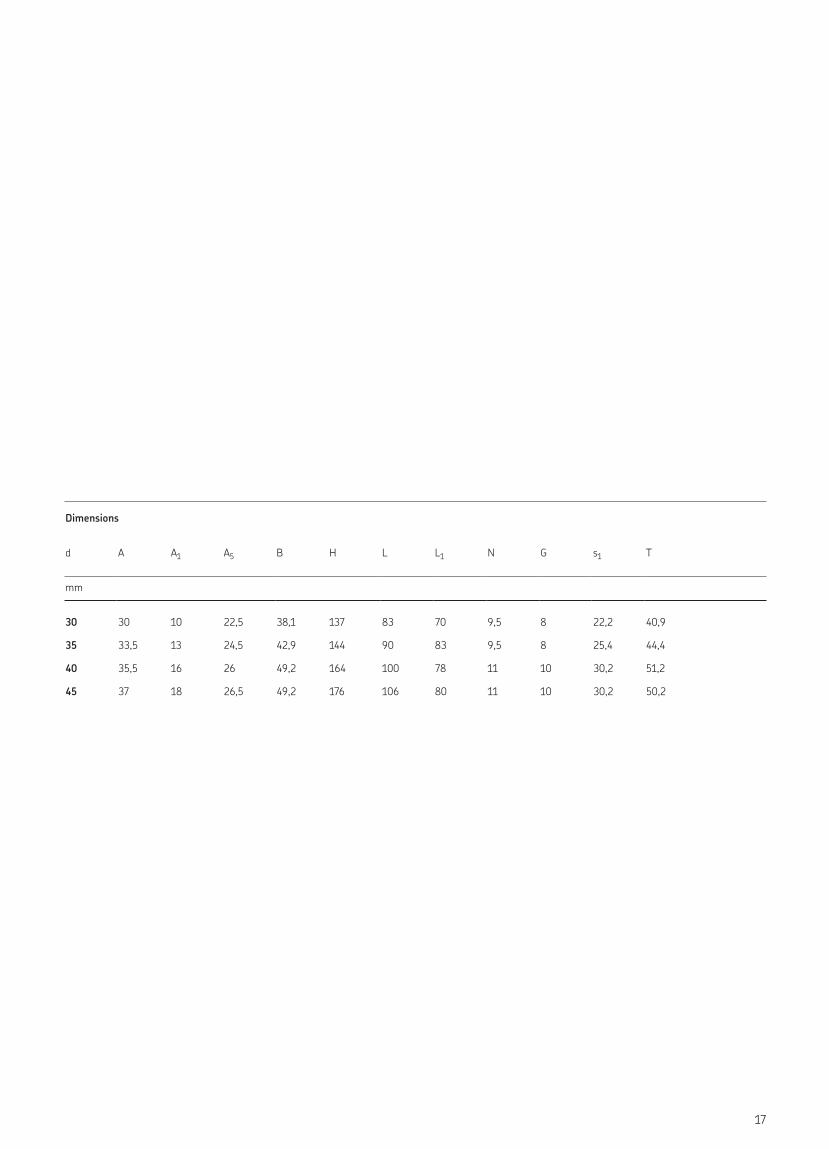
Dimensions
d A A1 A5 B H L L1 N G s1 T
mm
30 30 10 22,5 38,1 137 83 70 9,5 8 22,2 40,9
35 33,5 13 24,5 42,9 144 90 83 9,5 8 25,4 44,4
40 35,5 16 26 49,2 164 100 78 11 10 30,2 51,2
45 37 18 26,5 49,2 176 106 80 11 10 30,2 50,2
17
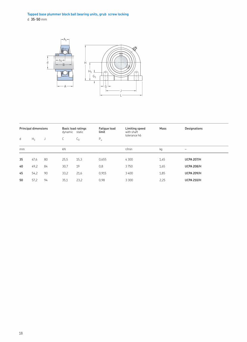
Tapped base plummer block ball bearing units, grub screw lockingd 35-50 mm
Principal dimensions Basic load ratings Fatigue load limit
Limiting speed Mass Designationsdynamic static with shaft
tolerance h6d H1 J C C0 Pu
mm kN r/min kg –
35 47,6 80 25,5 15,3 0,655 4 300 1,45 UCPA 207/H
40 49,2 84 30,7 19 0,8 3 750 1,65 UCPA 208/H
45 54,2 90 33,2 21,6 0,915 3 400 1,85 UCPA 209/H
50 57,2 94 35,1 23,2 0,98 3 300 2,25 UCPA 210/H
A1
H1
H
GJL
G1
s1dB
A
18
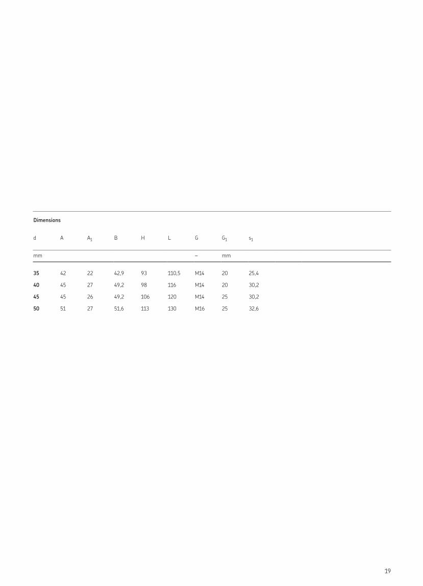
Dimensions
d A A1 B H L G G1 s1
mm – mm
35 42 22 42,9 93 110,5 M14 20 25,4
40 45 27 49,2 98 116 M14 20 30,2
45 45 26 49,2 106 120 M14 25 30,2
50 51 27 51,6 113 130 M16 25 32,6
19
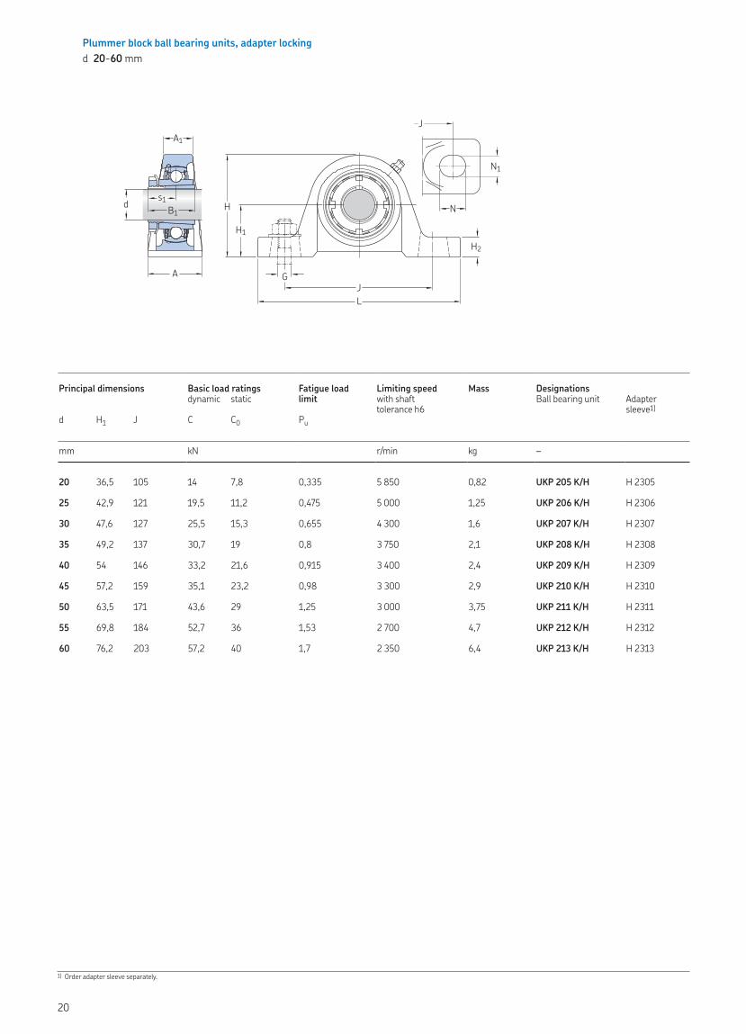
Plummer block ball bearing units, adapter lockingd 20-60 mm
Principal dimensions Basic load ratings Fatigue load limit
Limiting speed Mass Designationsdynamic static with shaft
tolerance h6Ball bearing unit Adapter
sleeve1)d H1 J C C0 Pu
mm kN r/min kg –
20 36,5 105 14 7,8 0,335 5 850 0,82 UKP 205 K/H H 2305
25 42,9 121 19,5 11,2 0,475 5 000 1,25 UKP 206 K/H H 2306
30 47,6 127 25,5 15,3 0,655 4 300 1,6 UKP 207 K/H H 2307
35 49,2 137 30,7 19 0,8 3 750 2,1 UKP 208 K/H H 2308
40 54 146 33,2 21,6 0,915 3 400 2,4 UKP 209 K/H H 2309
45 57,2 159 35,1 23,2 0,98 3 300 2,9 UKP 210 K/H H 2310
50 63,5 171 43,6 29 1,25 3 000 3,75 UKP 211 K/H H 2311
55 69,8 184 52,7 36 1,53 2 700 4,7 UKP 212 K/H H 2312
60 76,2 203 57,2 40 1,7 2 350 6,4 UKP 213 K/H H 2313
1) Order adapter sleeve separately.
N1
N
JA1
A
H1H2
H
JL
G
d B1s1
20
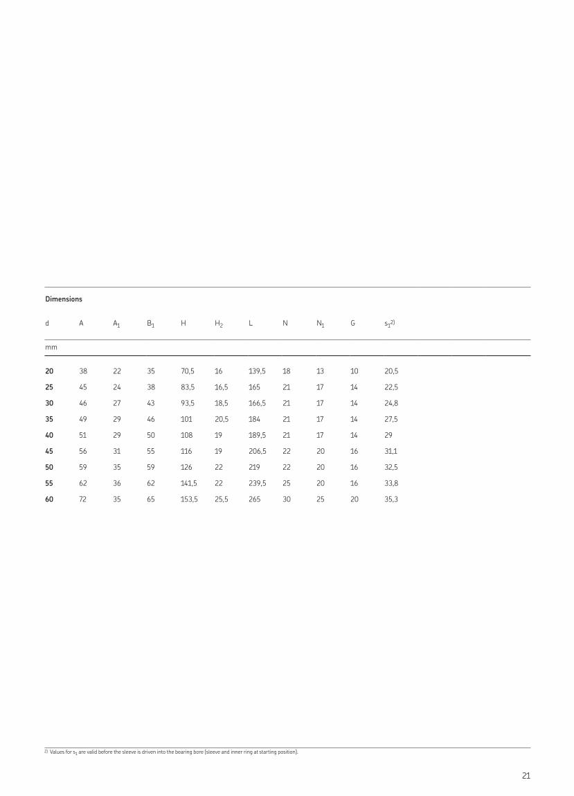
Dimensions
d A A1 B1 H H2 L N N1 G s12)
mm
20 38 22 35 70,5 16 139,5 18 13 10 20,5
25 45 24 38 83,5 16,5 165 21 17 14 22,5
30 46 27 43 93,5 18,5 166,5 21 17 14 24,8
35 49 29 46 101 20,5 184 21 17 14 27,5
40 51 29 50 108 19 189,5 21 17 14 29
45 56 31 55 116 19 206,5 22 20 16 31,1
50 59 35 59 126 22 219 22 20 16 32,5
55 62 36 62 141,5 22 239,5 25 20 16 33,8
60 72 35 65 153,5 25,5 265 30 25 20 35,3
2) Values for s1 are valid before the sleeve is driven into the bearing bore (sleeve and inner ring at starting position).
21
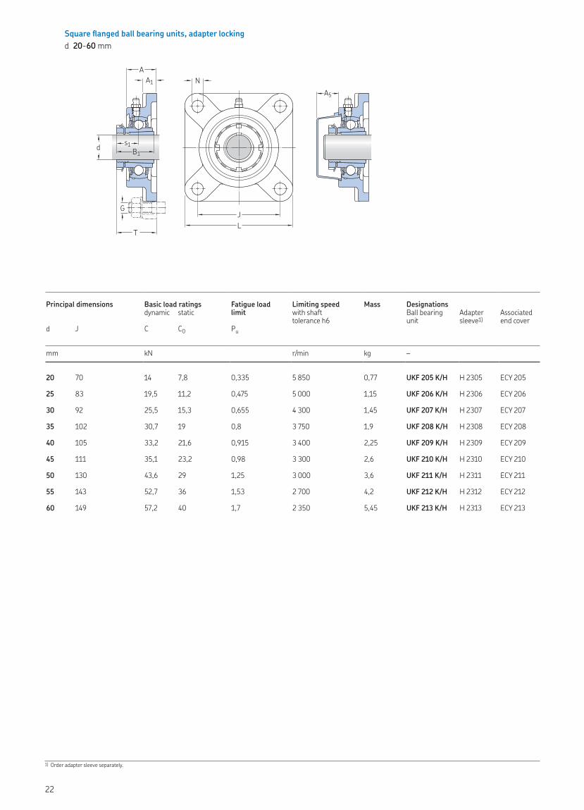
Square flanged ball bearing units, adapter lockingd 20-60 mm
Principal dimensions Basic load ratings Fatigue load limit
Limiting speed Mass Designations dynamic static with shaft
tolerance h6Ball bearing unit
Adapter sleeve1)
Associated end cover
d J C C0 Pu
mm kN r/min kg –
20 70 14 7,8 0,335 5 850 0,77 UKF 205 K/H H 2305 ECY 205
25 83 19,5 11,2 0,475 5 000 1,15 UKF 206 K/H H 2306 ECY 206
30 92 25,5 15,3 0,655 4 300 1,45 UKF 207 K/H H 2307 ECY 207
35 102 30,7 19 0,8 3 750 1,9 UKF 208 K/H H 2308 ECY 208
40 105 33,2 21,6 0,915 3 400 2,25 UKF 209 K/H H 2309 ECY 209
45 111 35,1 23,2 0,98 3 300 2,6 UKF 210 K/H H 2310 ECY 210
50 130 43,6 29 1,25 3 000 3,6 UKF 211 K/H H 2311 ECY 211
55 143 52,7 36 1,53 2 700 4,2 UKF 212 K/H H 2312 ECY 212
60 149 57,2 40 1,7 2 350 5,45 UKF 213 K/H H 2313 ECY 213
1) Order adapter sleeve separately.
T
G
AA1
JL
N
d B1s1
A5
22
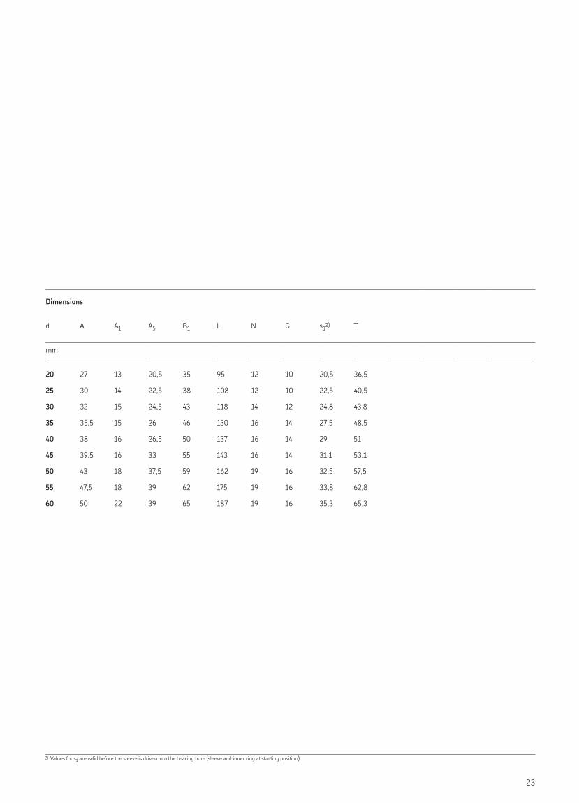
Dimensions
d A A1 A5 B1 L N G s12) T
mm
20 27 13 20,5 35 95 12 10 20,5 36,5
25 30 14 22,5 38 108 12 10 22,5 40,5
30 32 15 24,5 43 118 14 12 24,8 43,8
35 35,5 15 26 46 130 16 14 27,5 48,5
40 38 16 26,5 50 137 16 14 29 51
45 39,5 16 33 55 143 16 14 31,1 53,1
50 43 18 37,5 59 162 19 16 32,5 57,5
55 47,5 18 39 62 175 19 16 33,8 62,8
60 50 22 39 65 187 19 16 35,3 65,3
2) Values for s1 are valid before the sleeve is driven into the bearing bore (sleeve and inner ring at starting position).
23
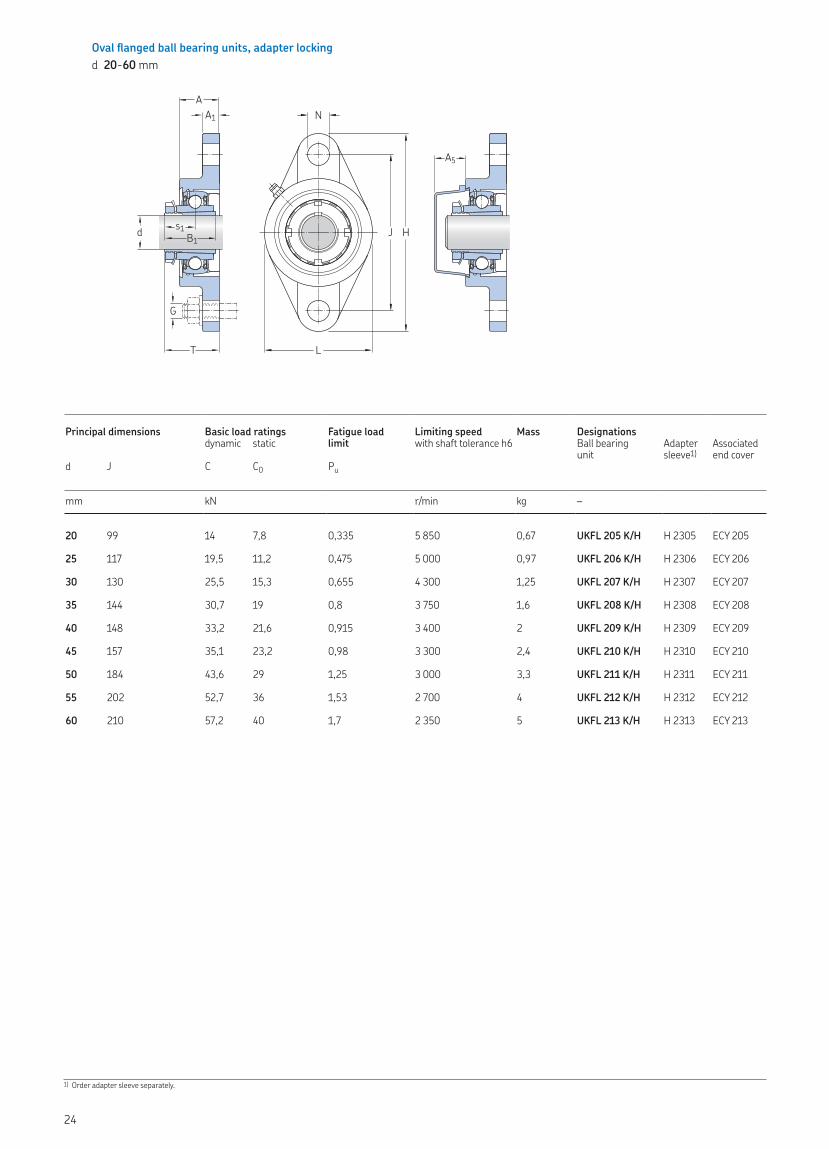
Oval flanged ball bearing units, adapter lockingd 20-60 mm
Principal dimensions Basic load ratings Fatigue load limit
Limiting speed Mass Designations dynamic static with shaft tolerance h6 Ball bearing
unitAdapter sleeve1)
Associated end cover
d J C C0 Pu
mm kN r/min kg –
20 99 14 7,8 0,335 5 850 0,67 UKFL 205 K/H H 2305 ECY 205
25 117 19,5 11,2 0,475 5 000 0,97 UKFL 206 K/H H 2306 ECY 206
30 130 25,5 15,3 0,655 4 300 1,25 UKFL 207 K/H H 2307 ECY 207
35 144 30,7 19 0,8 3 750 1,6 UKFL 208 K/H H 2308 ECY 208
40 148 33,2 21,6 0,915 3 400 2 UKFL 209 K/H H 2309 ECY 209
45 157 35,1 23,2 0,98 3 300 2,4 UKFL 210 K/H H 2310 ECY 210
50 184 43,6 29 1,25 3 000 3,3 UKFL 211 K/H H 2311 ECY 211
55 202 52,7 36 1,53 2 700 4 UKFL 212 K/H H 2312 ECY 212
60 210 57,2 40 1,7 2 350 5 UKFL 213 K/H H 2313 ECY 213
1) Order adapter sleeve separately.
AA1
T
G
N
L
J Hd B1s1
A5
24
Dimensions
d A A1 A5 B1 H L N G s12) T
mm
20 27 13 20,5 35 130 68 16 14 20,5 36,5
25 30 13 22,5 38 147,5 80 16 14 22,5 40,5
30 32 14 24,5 43 161 90 16 14 24,8 43,8
35 34 14 26 46 174,5 100 16 14 27,5 48,5
40 35 15 26,5 50 188 108 19 16 29 51
45 39 15 33 55 197 115 19 16 31,1 53,1
50 41,5 18 37,5 59 224 130 19 16 32,5 57,5
55 45 18 39 62 250 140 23 20 33,8 62,8
60 47 20 39 65 258 155 23 20 35,3 65,3
2) Values for s1 are valid before the sleeve is driven into the bearing bore (sleeve and inner ring at starting position).
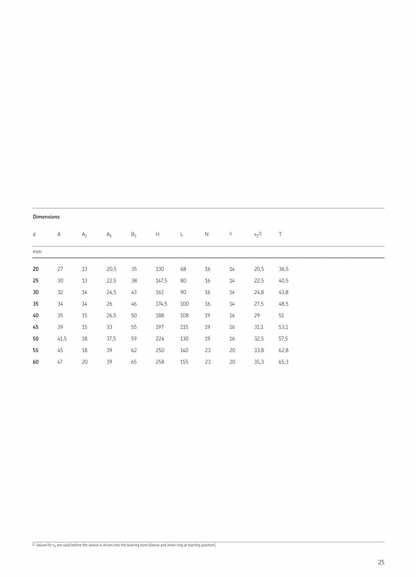
25
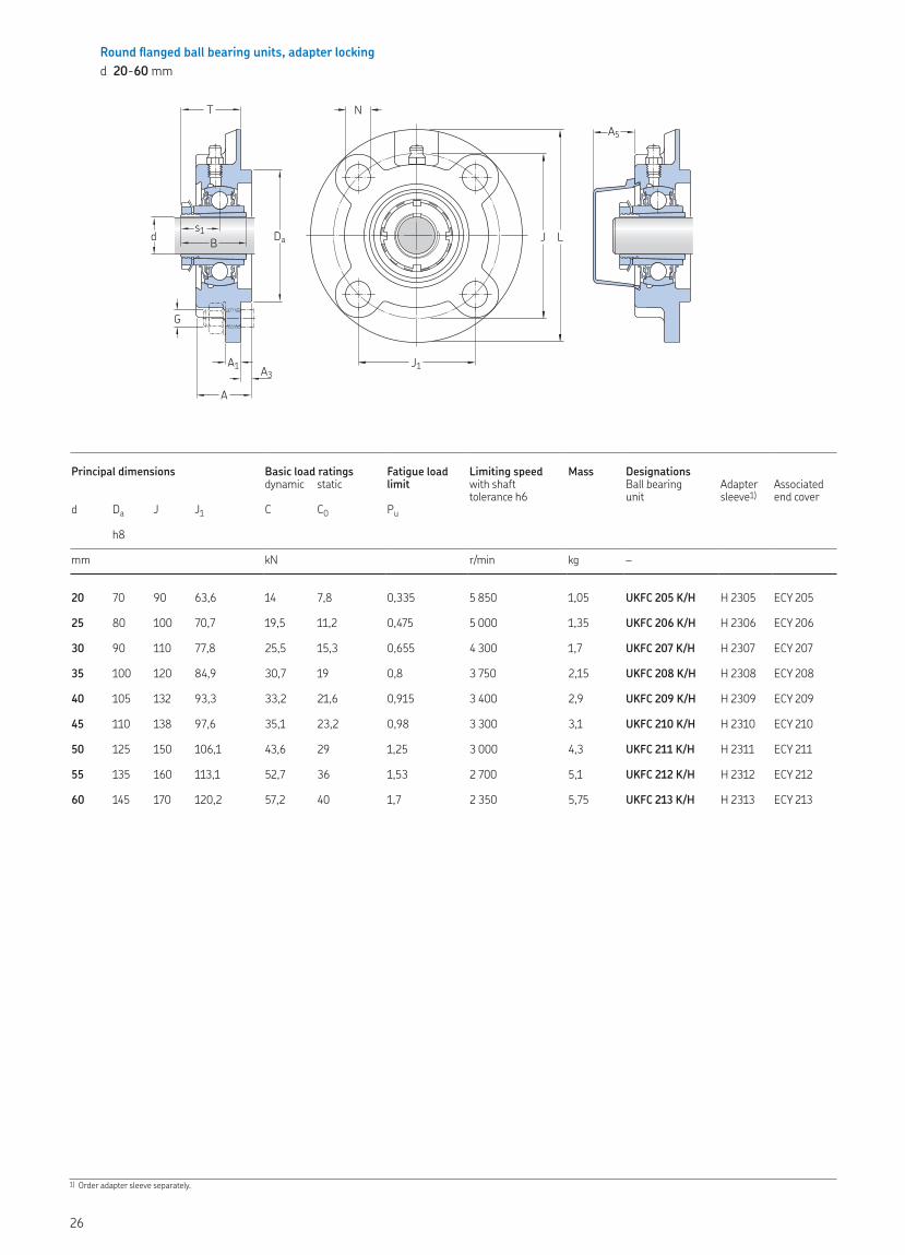
Round flanged ball bearing units, adapter lockingd 20-60 mm
Principal dimensions Basic load ratings Fatigue load limit
Limiting speed Mass Designations dynamic static with shaft
tolerance h6Ball bearing unit
Adapter sleeve1)
Associated end cover
d Da J J1 C C0 Pu
h8
mm kN r/min kg –
20 70 90 63,6 14 7,8 0,335 5 850 1,05 UKFC 205 K/H H 2305 ECY 205
25 80 100 70,7 19,5 11,2 0,475 5 000 1,35 UKFC 206 K/H H 2306 ECY 206
30 90 110 77,8 25,5 15,3 0,655 4 300 1,7 UKFC 207 K/H H 2307 ECY 207
35 100 120 84,9 30,7 19 0,8 3 750 2,15 UKFC 208 K/H H 2308 ECY 208
40 105 132 93,3 33,2 21,6 0,915 3 400 2,9 UKFC 209 K/H H 2309 ECY 209
45 110 138 97,6 35,1 23,2 0,98 3 300 3,1 UKFC 210 K/H H 2310 ECY 210
50 125 150 106,1 43,6 29 1,25 3 000 4,3 UKFC 211 K/H H 2311 ECY 211
55 135 160 113,1 52,7 36 1,53 2 700 5,1 UKFC 212 K/H H 2312 ECY 212
60 145 170 120,2 57,2 40 1,7 2 350 5,75 UKFC 213 K/H H 2313 ECY 213
1) Order adapter sleeve separately.
G
d Bs1
T
Da
A1 A3
A
N
J1
J L
A5
26
Dimensions
d A A1 A3 A5 B1 L N G s12) T
mm
20 27,5 7 6 20,5 35 115 12 10 20,5 30,5
25 30 8 8 22,5 38 125 12 10 22,5 32,5
30 32 9 8 24,5 43 135 14 12 24,8 35,8
35 35,5 9 10 26 46 145 14 12 27,5 38,5
40 37,5 14 12 26,5 50 160 16 14 29 39
45 39 14 12 33 55 165 16 14 31,1 41,1
50 43 15 12 37,5 59 185 19 16 32,5 45,5
55 47,5 15 12 39 62 195 19 16 33,8 50,8
60 50 15 14 39 65 205 19 16 35,3 51,3
2) Values for s1 are valid before the sleeve is driven into the bearing bore (sleeve and inner ring at starting position).
27
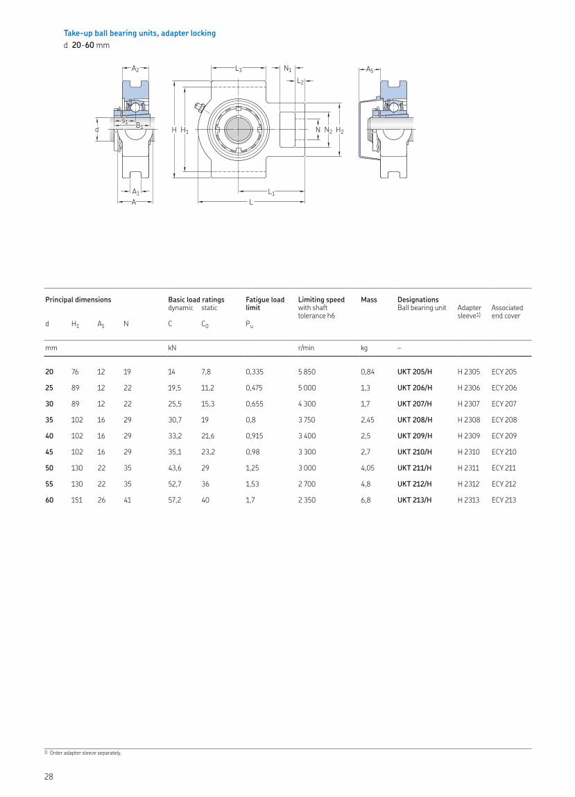
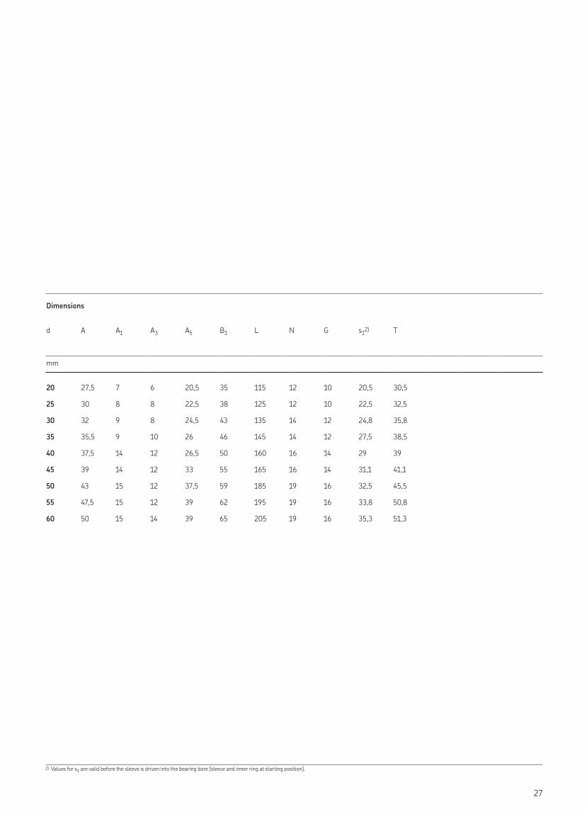
Take-up ball bearing units, adapter lockingd 20-60 mm
Principal dimensions Basic load ratings Fatigue load limit
Limiting speed Mass Designations dynamic static with shaft
tolerance h6Ball bearing unit Adapter
sleeve1)Associated end cover
d H1 A1 N C C0 Pu
mm kN r/min kg –
20 76 12 19 14 7,8 0,335 5 850 0,84 UKT 205/H H 2305 ECY 205
25 89 12 22 19,5 11,2 0,475 5 000 1,3 UKT 206/H H 2306 ECY 206
30 89 12 22 25,5 15,3 0,655 4 300 1,7 UKT 207/H H 2307 ECY 207
35 102 16 29 30,7 19 0,8 3 750 2,45 UKT 208/H H 2308 ECY 208
40 102 16 29 33,2 21,6 0,915 3 400 2,5 UKT 209/H H 2309 ECY 209
45 102 16 29 35,1 23,2 0,98 3 300 2,7 UKT 210/H H 2310 ECY 210
50 130 22 35 43,6 29 1,25 3 000 4,05 UKT 211/H H 2311 ECY 211
55 130 22 35 52,7 36 1,53 2 700 4,8 UKT 212/H H 2312 ECY 212
60 151 26 41 57,2 40 1,7 2 350 6,8 UKT 213/H H 2313 ECY 213
1) Order adapter sleeve separately.
A1
A2
A
H H1 N2 H2
N1L2
N
L1
L3
L
d B1s1
A5
28
Dimensions
d A A2 A5 B1 H H2 L L1 L2 L3 N1 N2 s12)
mm
20 32 24 20,5 35 89 51 97 62 10 51 16 32 20,5
25 37 28 22,5 38 102 56 113 70 10 57 16 37,5 22,5
30 37 30 24,5 43 102 64 129 78 13 64 16 37,5 24,8
35 49 33 26 46 114 83 145 88 16 83 19 49 27,5
40 49 35 26,5 50 117 83 145 87 16 83 21 51 29
45 49 37 33 55 117 83 148 90 16 86 19 49 31,1
50 64 38 37,5 59 146 102 172 106 19 95 25 64,5 32,5
55 64 42 39 62 146 102 194 119 19 102 32 64,5 33,8
60 70 44 39 65 167 111 225 137 21 121 32 70 35,3
2) Values for s1 are valid before the sleeve is driven into the bearing bore (sleeve and inner ring at starting position).
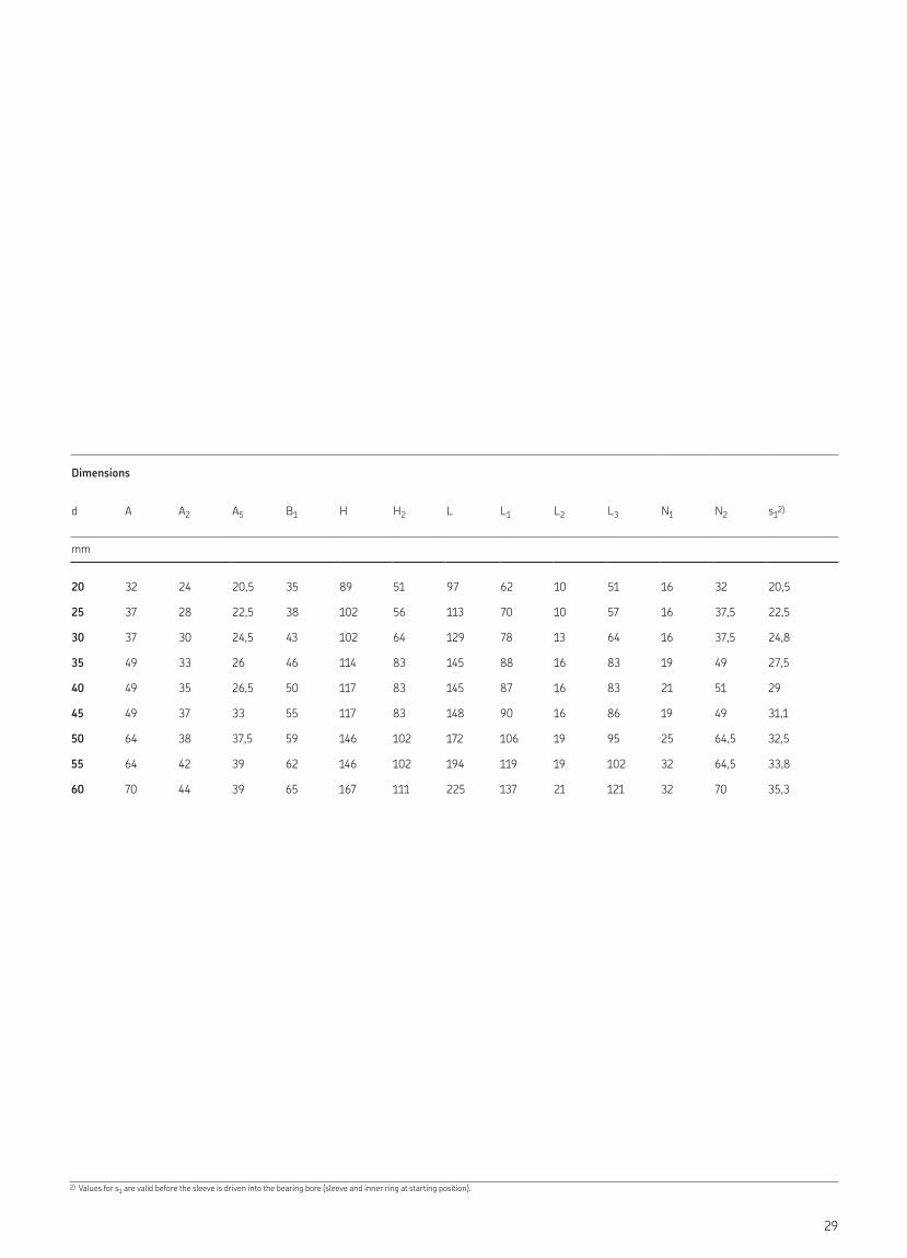
29
3-bolt bracket flanged ball bearing units, adapter lockingd 25-40 mm
Principal dimensions Basic load ratings Fatigue load limit
Limiting speed Mass Designations dynamic static with shaft
tolerance h6Ball bearing unit Adapter
sleeve1)Associated end cover
d H1 J J1 C C0 Pu
mm kN r/min kg –
25 50 40 29 19,5 11,2 0,475 5 000 1,1 UKFB 206 K/H H 2306 ECY 206
30 55 46 32 25,5 15,3 0,655 4 300 1,5 UKFB 207 K/H H 2307 ECY 207
35 60 50 41 30,7 19 0,8 3 750 1,95 UKFB 208 K/H H 2308 ECY 208
40 65 54 43 33,2 21,6 0,915 3 400 2,3 UKFB 209 K/H H 2309 ECY 209
1) Order adapter sleeve separately.
A
TA1
N
JL1
L
H
H1
J1
dB1
s1
A5
G
30
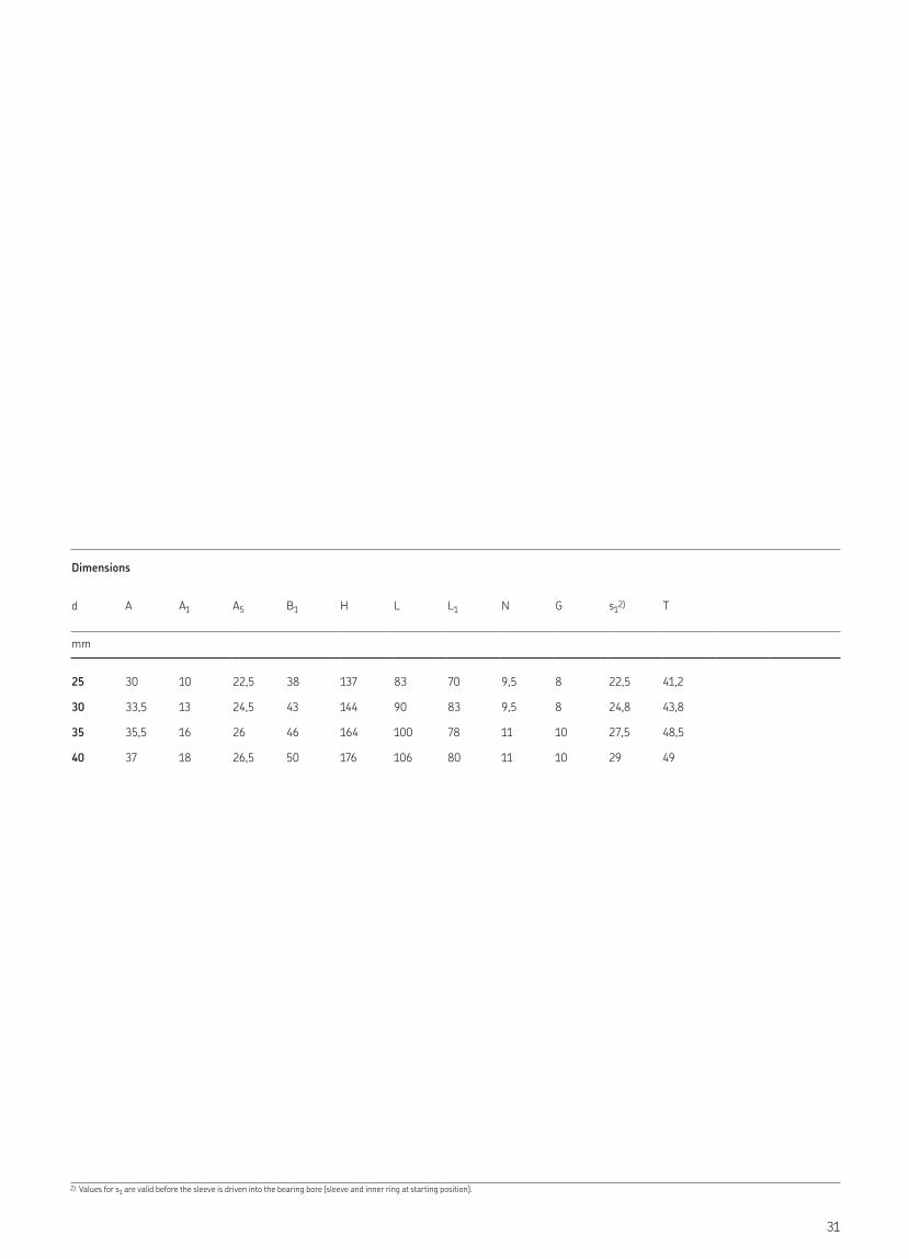
Dimensions
d A A1 A5 B1 H L L1 N G s12) T
mm
25 30 10 22,5 38 137 83 70 9,5 8 22,5 41,2
30 33,5 13 24,5 43 144 90 83 9,5 8 24,8 43,8
35 35,5 16 26 46 164 100 78 11 10 27,5 48,5
40 37 18 26,5 50 176 106 80 11 10 29 49
2) Values for s1 are valid before the sleeve is driven into the bearing bore (sleeve and inner ring at starting position).
31
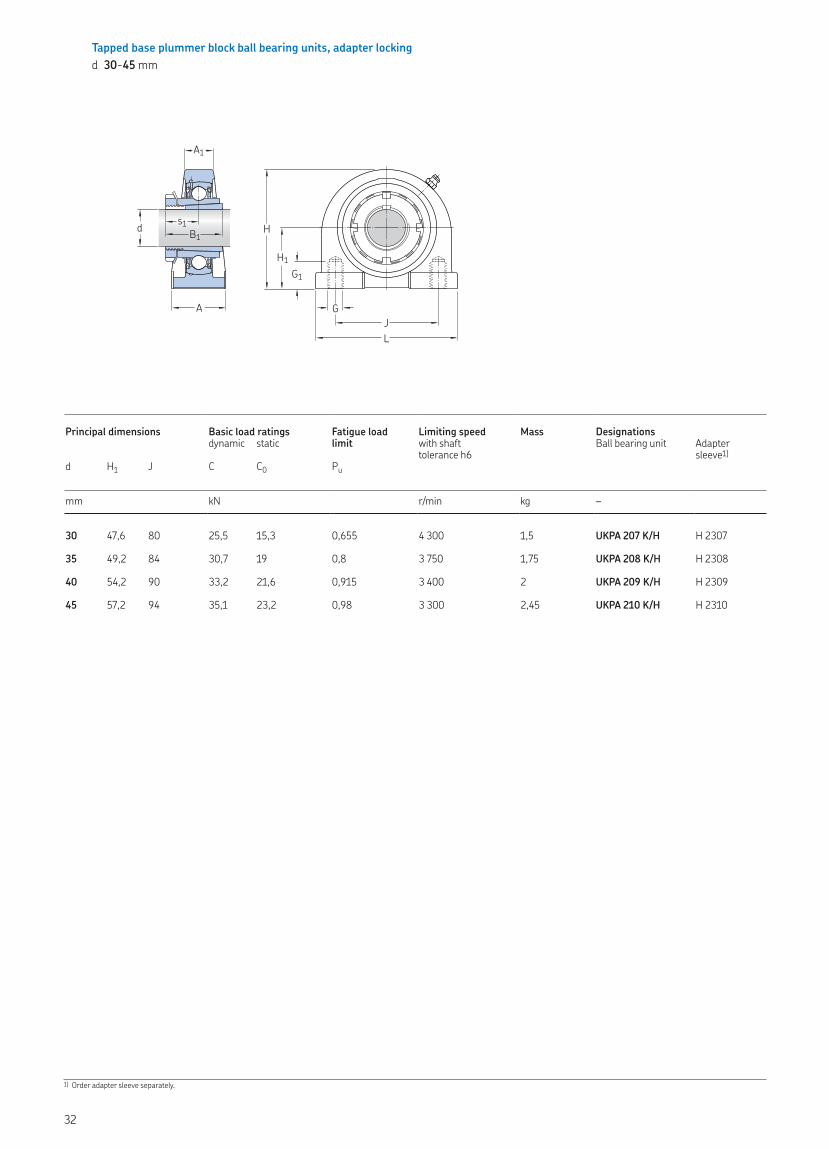
Tapped base plummer block ball bearing units, adapter lockingd 30-45 mm
Principal dimensions Basic load ratings Fatigue load limit
Limiting speed Mass Designationsdynamic static with shaft
tolerance h6Ball bearing unit Adapter
sleeve1)d H1 J C C0 Pu
mm kN r/min kg –
30 47,6 80 25,5 15,3 0,655 4 300 1,5 UKPA 207 K/H H 2307
35 49,2 84 30,7 19 0,8 3 750 1,75 UKPA 208 K/H H 2308
40 54,2 90 33,2 21,6 0,915 3 400 2 UKPA 209 K/H H 2309
45 57,2 94 35,1 23,2 0,98 3 300 2,45 UKPA 210 K/H H 2310
1) Order adapter sleeve separately.
A1
H1
H
GJL
G1
A
d B1s1
32
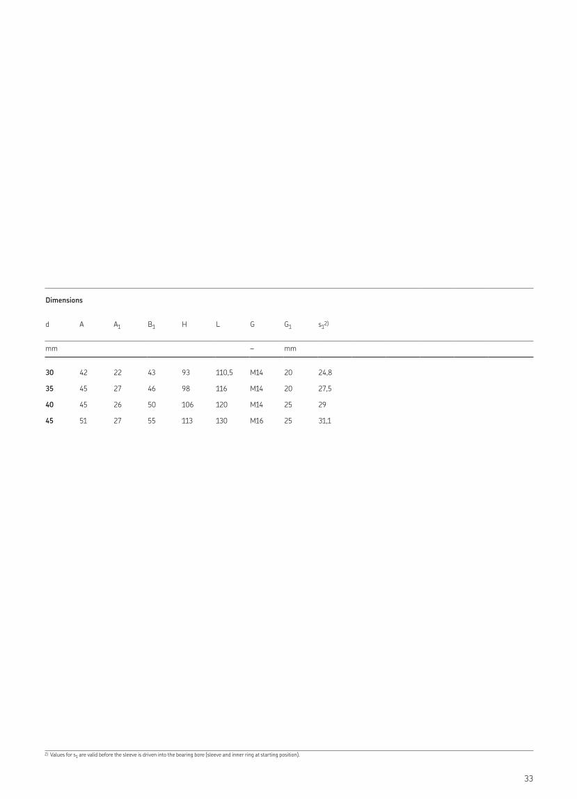
Dimensions
d A A1 B1 H L G G1 s12)
mm – mm
30 42 22 43 93 110,5 M14 20 24,8
35 45 27 46 98 116 M14 20 27,5
40 45 26 50 106 120 M14 25 29
45 51 27 55 113 130 M16 25 31,1
2) Values for s1 are valid before the sleeve is driven into the bearing bore (sleeve and inner ring at starting position).
33

skf.com® SKF is a registered trademark of the SKF Group.
© SKF Group 2018The contents of this publication are the copyright of the publisher and may not be reproduced (even extracts) unless prior written permission is granted. Every care has been taken to ensure the accuracy of the information contained in this publication but no liability can be accepted for any loss or damage whether direct, indirect or consequential arising out of the use of the information contained herein.PUB BU/P2 17987 EN · June 2018Certain image(s) used under license from Shutterstock.com.


